mech 4240 critical design review: child mobility device
TRANSCRIPT

MECH 4240 Critical Design Review: Child Mobility Device
Corp #8
Neil Granberry, Manager Nathan McWhirter, Scribe
Jaron Breland Daniel Frack
Jay Gandhakwala Callie Smith
Industrial Sponsors: Christina Duke, Bonnie Wilson
Technical Advisors: Dr. Scott Renner, Dr. David Beale
Overlord: Dr. David Beale

Abstract A better system is needed for transporting a threeyearold child with special needs and
all his medical equipment. Due to the large amount of equipment that he requires, this transportation device must have increased storage capacity and be further customized to fit the child’s needs. The client currently uses a twoseat model with a relatively small amount of storage space, such that much of the equipment is stacked precariously in the seats. This report elaborates the systems engineering approach to solve this design problem. The mission of Corp 8 is “to provide a comfortable means of transportation for a threeyearold child with special needs and an effective and convenient means of storage for all the necessary medical equipment.”
It was determined early on that it would be best for the client and the team if a commercial twoseat stroller were purchased and modified. Through the use of trade studies and decision matrices, the Chicco Cortina Together stroller was chosen as the base model for these modifications, which include removal of the rear seat and the addition of five subsystems: an IV pole, removable tray, extended footrest, storage shelf, and oxygen tank storage. Alternative arrangements of these subsystems were investigated in the preliminary design phase, prototypes were tested, and the concepts were improved to produce a final detailed system design.
The subsystems are now constructed as follows: The 15inch IV pole includes a single small hook, screws into the stroller frame, and can pivot for storage. The tray will be plastic molded and will use new quickconnect pieces to attach to the stroller frame. The footrest will be molded out of multiple carbon fiber parts which will be glued together. The sliding shelf will be only one layer and slide completely out the back like a drawer, enabling full access to basket storage without removing any bags from the shelf. The small oxygen tank will hang from a hook and hammock combination attached to the frame near the parent tray, and the large oxygen tank will be stored vertically behind the seat, in a customized carrying bag strapped to the frame.
1

Table of Contents
Abstract
Table of Contents
1.0 Introduction
2.0 Mission Objective
3.0 Mission Environment
4.0 System Requirements
5.0 Architectural Design
5.1 Trade Studies
5.2 Product Hierarchy
5.3 Subsystems Design Engineering
5.4 IV Pole
5.5 Removable Tray
5.5.1 Preliminary Tray Design
5.5.2 Final Tray Design
5.6 Extended Footrest
5.6.1 Preliminary Footrest Design
5.6.2 Final Footrest Design
5.7 Shelf Alternatives
5.7.1 Preliminary Alternative 1: Folding Shelf
5.7.2 Preliminary Alternative 2: Static Shelf
5.7.3 Preliminary Alternative 3: Stackable Sliding Shelf
5.7.4 Final Design for Shelf Storage
5.8 Oxygen Tank Storage Alternatives
2

5.8.1 Preliminary Alternative 1: Underseat Tank Storage
5.8.2 Preliminary Alternative 2: Tank Cupholders
5.8.3 Final Design for Oxygen Tank Storage
5.8.3.1 Final Design for Small Oxygen Tank Storage
5.8.3.2 Final Design for Large Oxygen Tank Storage
5.9 Bill of Materials
6.0 Interfaces
7.0 Concept of Operations
8.0 Validate and Verify
9.0 Risk Management
10.0 Technical Resource Budget Tracking
11.0 Configuration Management and Documentation
12.0 Project Management
13.0 Conclusions
References
Appendix A: IV Pole Calculations
Appendix B: Finite Element Analysis Results
Appendix C: Shelf Trade Studies
Appendix D: Full Bill of Materials
Appendix E: High Chair
Appendix F: Detailed Design Drawings
3

1.0 Introduction
Ryan Duke, shown in Figure 1, is a threeyearold child who was born prematurely and has special needs. He has a tracheotomy which necessitates the regular use of a vent, suction bag, and food pump wherever he goes. He also needs a large and a small oxygen tank, a diaper bag, and an emergency bag. Due to these special requirements, offtheshelf designs of most commercial strollers are not suitable for Ryan and his needs. The engineering need is for a new mobility device with sufficient storage and strength to hold Ryan and all his equipment, and reliability to last through two years of use.
The stroller currently being used by the client (Christina Duke, Ryan’s mother) is the Graco Ready2Grow Classic Connect, a twoseat model with a relatively small amount of storage space. Because of this lack of room, most of the equipment must be stacked precariously in the seats or on top of other items while Ryan rides in the seat closest to the driver.
Figure 1: Ryan Duke
This report will first present the background and requirements for the mobility device design, and the decisionmaking process for a commercial stroller from preliminary research to final selection. The architectural design and interfacing of all additions and modifications, for both preliminary and final designs, will be reviewed and detailed. Then the concept of operations, requirements verification, and risk management will be presented. The project’s organization will be covered, including budgets, documentation, and other general management. Finally, the conclusions of the report will be summarized.
4

2.0 Mission Objective The objective is to provide a comfortable means of transportation for a threeyearold
child with special needs and an effective and convenient means of storage for all the necessary medical equipment.
3.0 Mission Environment The current stroller is used in various outofhome environments. Christina must often
bring Ryan to doctors’ offices, which have narrow doorways that the stroller needs to fit through. Also, this onthego nature means that the equipment and bags must always be accessible to the operator for any situation that may arise, whether everyday or in an emergency.
Another major part of the design is its storage. The folded device must fit in the trunk of Christina’s car, a 2007 Honda Odyssey. To meet this constraint, any modifications should not lengthen the stroller by more than six inches in the folded width.
4.0 System Requirements
I. The device shall include a storage system with sufficient space for all equipment. a. Storage space shall be unobstructed for easy access to bags and objects, which
may include the vent, suction bag, emergency bag, feeding bag and pump, diaper bag, and personal accessories.
b. Holders shall be provided to store and support both oxygen tanks. c. An IV pole shall be attached for use of the feeding bag and pump.
II. The device shall be easily maneuverable in rooms, hallways, and doorways. III. The device shall collapse to fit in the trunk of Christina’s car, a 2007 Honda Odyssey.
a. Folded frame dimensions shall not be significantly larger than the current model. b. Any additions or modifications shall not significantly increase these dimensions.
IV. The device shall provide safety, stability, and comfort for the child. a. The seat belt system shall keep the child safe without constricting his movement. b. The frame shall fully support the weight of the child and his equipment. c. The wheels shall have a locking system to stabilize against rocking.
V. The device shall provide sun protection for the child when necessary. VI. The device shall accommodate two years of the child’s growth. VII. The device shall allow the child to face forward. VIII. The device shall meet existing standards and requirements for both strollers and
disability equipment.
5
5.0 Architectural Design The first major design decision for this project was whether to build a new device from
the ground up or to customize and modify an existing stroller model. After meeting with Christina and discussing her current stroller and its problems, it was concluded that an existing model could easily be adapted to meet Christina and Ryan’s needs.
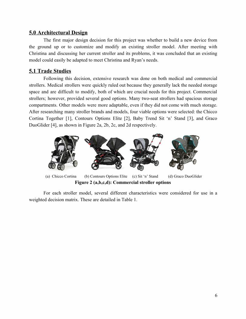
5.1 Trade Studies Following this decision, extensive research was done on both medical and commercial
strollers. Medical strollers were quickly ruled out because they generally lack the needed storage space and are difficult to modify, both of which are crucial needs for this project. Commercial strollers; however, provided several good options. Many twoseat strollers had spacious storage compartments. Other models were more adaptable, even if they did not come with much storage. After researching many stroller brands and models, four viable options were selected: the Chicco Cortina Together [1], Contours Options Elite [2], Baby Trend Sit ‘n’ Stand [3], and Graco DuoGlider [4], as shown in Figure 2a, 2b, 2c, and 2d respectively.
(a) Chicco Cortina (b) Contours Options Elite (c) Sit ‘n’ Stand (d) Graco DuoGlider
Figure 2 (a,b,c,d): Commercial stroller options
For each stroller model, several different characteristics were considered for use in a weighted decision matrix. These are detailed in Table 1.
6
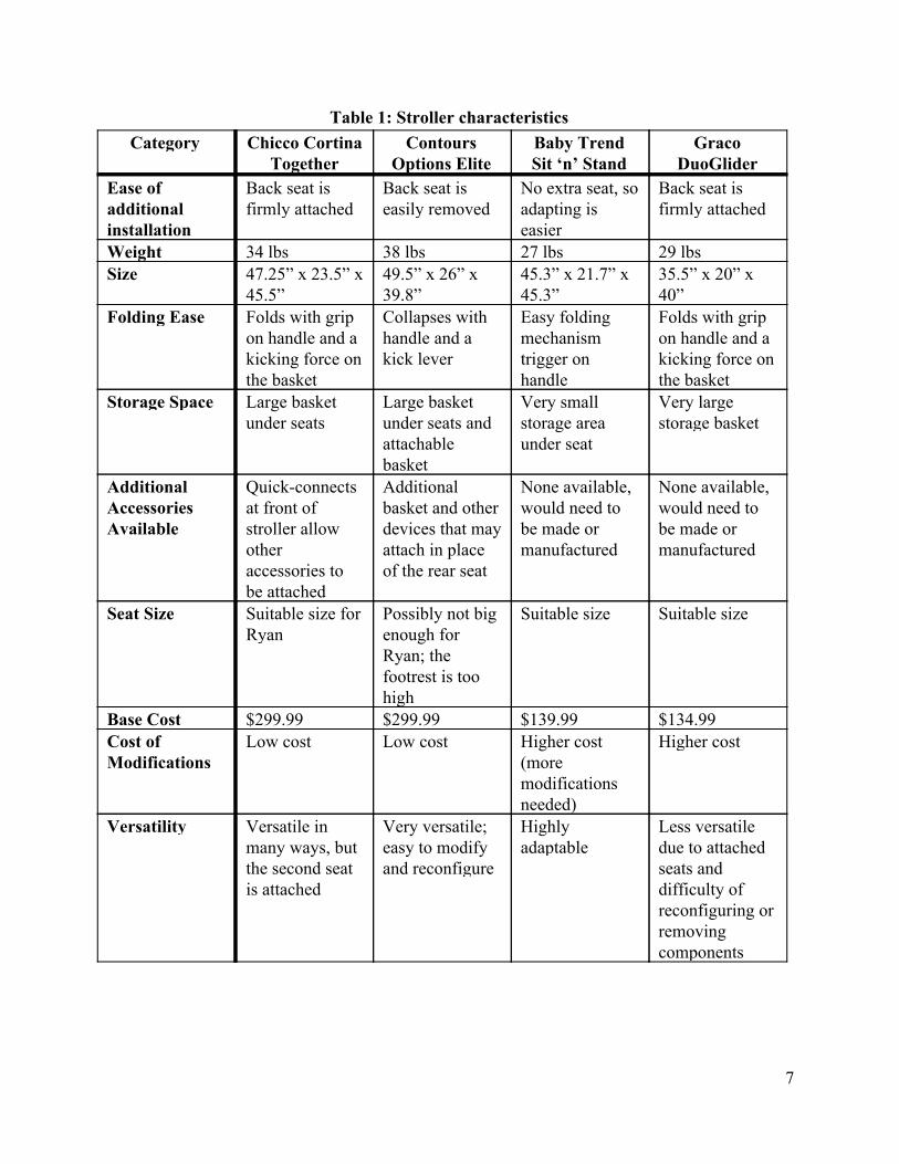
Table 1: Stroller characteristics Category Chicco Cortina
Together Contours
Options Elite Baby Trend Sit ‘n’ Stand
Graco DuoGlider
Ease of additional installation
Back seat is firmly attached
Back seat is easily removed
No extra seat, so adapting is easier
Back seat is firmly attached
Weight 34 lbs 38 lbs 27 lbs 29 lbs Size 47.25” x 23.5” x
45.5” 49.5” x 26” x 39.8”
45.3” x 21.7” x 45.3”
35.5” x 20” x 40”
Folding Ease Folds with grip on handle and a kicking force on the basket
Collapses with handle and a kick lever
Easy folding mechanism trigger on handle
Folds with grip on handle and a kicking force on the basket
Storage Space Large basket under seats
Large basket under seats and attachable basket
Very small storage area under seat
Very large storage basket
Additional Accessories Available
Quickconnects at front of stroller allow other accessories to be attached
Additional basket and other devices that may attach in place of the rear seat
None available, would need to be made or manufactured
None available, would need to be made or manufactured
Seat Size Suitable size for Ryan
Possibly not big enough for Ryan; the footrest is too high
Suitable size Suitable size
Base Cost $299.99 $299.99 $139.99 $134.99 Cost of Modifications
Low cost Low cost Higher cost (more modifications needed)
Higher cost
Versatility Versatile in many ways, but the second seat is attached
Very versatile; easy to modify and reconfigure
Highly adaptable
Less versatile due to attached seats and difficulty of reconfiguring or removing components
7

For the decision matrix, weighted scores were tabulated and results calculated for each team member with an Excel spreadsheet. Table 2 shows the manager’s table as an example and Table 3 shows each team member’s total score for each stroller.
Table 2: Example decision matrix
Characteristic Weight factor
Chicco Cortina
Total Options Elite
Total Sit ‘n’ Stand
Total Graco DuoGlider
Total
Ease of additional installation
4 3 12 3 12 3 12 2 8
Weight 2 3 6 2 4 4 8 3 6
Size 2 2 4 2 4 3 6 4 8
Folding ease 2 4 8 3 6 3 6 4 8
Storage space 5 4 20 4 20 3 15 5 25
Additional accessories
3 4 12 3 9 3 9 3 9
Seat size 4 3 12 2 8 3 12 3 12
Base cost 3 2 6 2 6 4 12 5 15
Additional cost
3 3 9 2 6 2 6 3 9
Versatility 3 5 15 4 12 4 12 3 9
Total weighted score:
104 87 98 109
8

Table 3: Team members’ decision matrix scores
Team Member Chicco Cortina Score
Options Elite Score
Sit ‘n’ Stand Score
Graco DuoGlider Score
Neil 104 87 98 109
Nathan 121 96 121 92
Callie 125 94 117 106
Daniel 120 119 114 107
Jaron 119 100 106 101
Jay 118 105 116 109
Average Score: 117.8 100.2 112 104
The average weighted score from the decision matrix above clearly indicated the Chicco
Cortina Together as the best choice. However, the final selection was not made until meeting and discussing all the options and results with Christina and with Dr. Renner, the team’s technical advisor. Christina also preferred the design of the Chicco Cortina for its versatility and maneuverability, and Dr. Renner agreed.
After this, the team contacted Chicco to ask about the potential for getting a free or discounted stroller. The company was able to provide a new Chicco Cortina stroller at no charge for the project. This stroller was measured and a model was built in SolidWorks to allow for different architectural designs and modifications of the stroller assembly.
5.2 Product Hierarchy
Five main subsystems will be added to the Chicco Cortina base model to satisfy all the system requirements and meet Ryan and Christina’s specific needs.
1. IV pole 2. Extended footrest 3. Removable tray 4. Storage shelf 5. Oxygen tank storage (small and large)
9

The IV pole is needed to support Ryan’s feeding bag whenever it needs to be used. The pole needs to be lightweight, compact, and must not hinder the device’s folding. The extended footrest is needed to accommodate Ryan’s growth over the next two years, providing better support for his feet and protection from the wheels. The removable tray is necessary for Ryan’s rehabilitation and dexterity activities, which requires plenty of space. The tray will also allow the stroller to be used like a high chair when traveling.
The addition of extra storage, including a shelf and oxygen tank holders, is a modification for which many design alternatives were considered. Shelf options include a folding, static, and sliding design. The tank storage must include accommodations for both the large and small tanks, and may be placed in a variety of locations: underneath the front seat, behind the seat, within the basket, or hanging attached to the frame.
These five subsystems, which include both their preliminary alternatives and final designs, are fully detailed in sections 5.4 through 5.9.
5.3 Subsystems Design Engineering
For elements that need to be added to the stroller, the first step was identifying the formdriving attributes. These were: stability against rocking, expanded storage space, seat restraints, support for the feeding bag, cupholders, tray space, a forward facing seat, wheel locks, sun protection, oxygen tank holders, and collapsing the stroller. For this part of the engineering design process, team members were split into two subgroups each assigned to their own half of the characteristics. As a brainstorming exercise to generate alternatives, each member independently came up with a morphological matrix of multiple possibilities to accomplish the desired functions. An example is shown in Figure 3 below.
Figure 3: Example morphological matrix
10

Some of these form driving characteristics are already adequately provided in the Chicco Cortina. Stability, seat restraints, cupholders, a forward facing seat, locking wheels, sun protection, and collapsibility are already inherent in the model. As long as no additions hinder the operation of these included subsystems, they will be suitable asis. However, the included restraint system will need to be modified to accommodate Ryan’s size as he grows over the next two years. This can easily be done by extending the straps.
In the following sections, design concepts for each subsystem and modification are provided, with initial designs from the first report followed by the modified final designs. Preliminary alternative designs are provided for the shelf and oxygen tank subsystems, which are closely interdependent in the system architecture.
An overview of the final stroller system is shown in Figure 4 below, and fully dimensioned drawings for all final parts and assemblies can be found in Appendix F.
Figure 4: Final stroller system with labeled subsystems
5.4 IV Pole A small IV pole attachment will be built to hang a feeding bag, which needs to be located
near Ryan’s head height. The preliminary design is shown in Figure 5a and the final improved design in Figure 5b.
11

Figure 5 (a, b): IV pole preliminary design and final design
This pole will be attached to the vertical bar of the stroller’s frame, just behind the front seat, as shown in Figure 6. There was only one IV pole concept considered in the preliminary design phase, and modifications have been minimal since then. Based on feedback from Christina, it was concluded that only one hook is really necessary. The top bar of the IV pole was also removed from the design, and the single backwardfacing hook will now be welded directly to the pole to minimize stresses and bending moments. The pole’s length was also increased from 8 inches to 15 inches, which enables the feeding bag and pump to be higher than Ryan’s waist while in use, a critical design requirement.
12

Figure 6: IV pole positioning
The IV pole subassembly will be composed of two main parts, the base and the hooked pole. The base is a machined block of aluminum with holes drilled into it. The lower two holes will allow it to be bolted to the stroller frame, and the third will be a threaded hole for a wing screw, which will also extend into to the frame.
For maximum stability, the pole is intended to be positioned vertically while in use; however, its angle may be adjusted by loosening the wing screw, moving the pole to the desired position, and retightening the wing screw. When it is stored parallel to the vertical bar of the frame, the pole will not interfere with the stroller’s folding.
The IV pole is designed to hold 5 pounds of vertical load. Detailed engineering calculations have been done to compute the associated factor of safety for bending, the maximum deflection, and the buckling load for the the designed pole diameter of 0.25 inches. These calculations are shown in Appendix A.
5.5 Removable Tray Another element which needs to be added to the front seat area is a tray. Many stroller
models come with a tray that is located in front of the child, but the Chicco Cortina does not. Additionally, most stroller tables are too small to facilitate Ryan’s rehabilitation activities. Although it lacks a full tray, the Chicco Cortina does include two quickconnect attachment options: either a bar that extends across the seat, or two cupholders.
13

5.5.1 Preliminary Tray Design
The tray must be at least nine inches long to provide space for Ryan’s rehabilitation exercises. It also needs to have a lip around the edge to prevent things from slipping off. A simple version of this tray was modeled as a preliminary design, and is shown in Figure 7.
Figure 7: Removable tray preliminary design
5.5.2 Final Tray Design
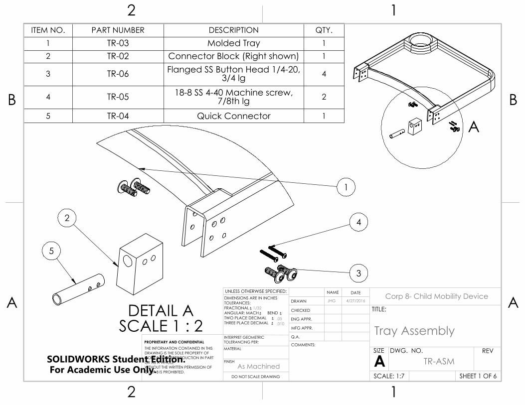
For the final design, Christina was consulted about Ryan’s needs for the tray. She noted that it would require a deeper tray surface to contain the items used in his rehabilitation and dexterity exercises, such as blocks, food, or any other toys or equipment. In addition, she desired that there be a cupholder built into the tray for Ryan to use. These requirements were incorporated into the design to create the final design for the tray, which is shown in Figure 8a, the connection detail in Figure 8b, and within the assembly in Figure 9.
Figure 8 (a,b): Removable tray final design and connection detail
14

Figure 9: Removable tray in stroller assembly
The new version of the tray is represented in the model using a shelled surface, because it will be vacuum formed out of plastic. This tray is designed with an angled surface at the connection point. This angle allows the tray to be flat and parallel to the ground rather than angled downward. Additionally, the surface itself is raised from the point of attachment, which will make it easier for Ryan to reach and access.
The tray will be attached to the stroller using the quickconnect system that is already built into the stroller. The point of connection on the tray has been left hollowed out, as is seen in Figure 8b. A block of Delrin plastic has been designed to fit into this hollow area. This block serves to house the quickconnect pins and allow secure attachment to the tray. Instead of using the existing quickconnect pins on the cupholders, the decision was made to manufacture additional pins with minor modifications. The manufactured pins are longer than the originals to allow for greater moment resistance while the tray is in use.
To fabricate a vacuumformed tray, a pattern or mold must be created so that the plastic will have the desired shape. Two alternative options are being considered to create the mold. The more economical option is to 3D print the lips and cupholder and affix them to a flat surface for the tray to complete the mold. The mold will then be taken to David Gowan in the department of Industrial Design, who will conduct the vacuum forming process. The second option is to manufacture a mold out of MDF (mediumdensity fiberboard) using a CNC machine. Many options were considered for the tray material, however ⅛” thick ABS plastic was the material recommended by David Gowan.
15

5.6 Extended Footrest
Considering the likely amount of growth for Ryan’s legs over the next two years of use, the footrest of the stroller will need to be adapted. This extended footrest design must provide additional support for his feet and protect them from hitting the wheels.
5.6.1 Preliminary Footrest Design
A simple version of the footrest was created for the preliminary design review. The idea was that it would sit on top of the current footrest and fold on a hinge for storage. The existing footrest, shown in Figure 10a, and the preliminary design, in Figure 10b, are presented below.
Figure 10 (a,b): Existing footrest and proposed preliminary design
5.6.2 Final Footrest Design
After beginning detailed design on the footrest, it was decided that a hinge connected to the current footrest would be too weak. The plastic would not be strong enough to screw through and support the weight of the new footrest, which was verified by bending the plastic by hand. Therefore, no calculations were needed to confirm this.
The decision was made to remove the existing plastic footrest of the Chicco Cortina and replace it with a molded carbon fiber design. This new footrest will extend two inches further forward than the existing one, and include sidewalls to further protect Ryan’s feet from the wheels and add structural support. It will attach to the aluminum rod underneath the current footrest, and will be prevented from rotating by hooking onto the sides of the frame through the grips shown below. The final footrest design is shown with its parts labeled in Figure 11a, and attached to the stroller in Figure 11b.
16

Figure 11 (a,b): Final footrest design and placement on stroller
Initially, the idea was to make the footrest out of one continuous piece of carbon fiber. However, after consulting with Jeff Thompson in the Polymer and Fiber Engineering Department, it was determined that it would be an overly intricate process to manufacture a mold for such a piece. It was then decided that the footrest assembly would be broken up into 5 pieces: the base, 2 sidewalls, and 2 grips. Pictures of these can be seen below in Figure 12 (ac), respectively, matching their orientations in Figure 11a.
Figure 12 (a,b,c): Footrest base, sidewall, and grip
The sidewalls will be made out of flat pieces of carbon fiber and will be cut to size, thus requiring no specific mold. The base will be created by placing half of a wooden dowel on a piece of foam. Drawings for the dowel and the other footrest parts are shown in Appendix F. The mold for the grip will be created out of foam. These parts will be attached together by either glue or epoxy, which will be determined by Jeff Thompson after selecting the type of carbon fiber to be used. This selection has not yet been finalized since it will consist of donated material. Drawings in Appendix F indicate a thickness of 0.20 inches for each part; however, the thickness is also not yet finalized. Upon the selection of the type of carbon fiber, the dimensions may need to be modified before beginning the molding process.
Four layers of carbon fiber will be used on a 0, 90, 45, and 0 degree pattern. Before assembly, the glue strength will be tested relative to the strength of continuous carbon fiber using
17

the following procedure: coupons will be cut out of the selected material after an isotropic triple layer at angles of 0, 90, and 45 degrees. The yield strength of the carbon fiber will then be determined by pulling the coupon apart with a tensile test machine. A second set of coupons will be cut and reattached using the desired glue. Finally, the new yield strength of the bonded carbon fiber will be determined from the second coupon set.
5.7 Shelf Alternatives
The designs described in the next four subsections relate to the addition of a shelf to support and access the most important medical equipment. The first three are preliminary alternative designs which were also discussed in the midterm report. Following these three, the fourth subsection is the final suggested design.
5.7.1 Preliminary Alternative 1: Folding Shelf
The shelf configuration shown in Figure 13a would be foldable so that storage space can be accessed underneath. The main benefits of this design were that it would effectively double the storage space and allow for important medical equipment to be easily accessed. The shelf would not interfere with the folding of the stroller in any way, and all of the frame components, specifically the top cross bar, would remain intact. This alternative would require side support on the shelf to secure the equipment when turning the stroller. This support could easily be provided by a simple netting system, as shown in Figure 13b.
Figure 13 (a,b): Folding shelf alternative
5.7.2 Preliminary Alternative 2: Static Shelf
The second concept, shown in Figure 14a, included a rigid shelf in between the top horizontal bars. This would keep the frame intact and maintain torsional support, while providing additional vertical storage space for all the components in Figure 14b. However, with the static
18

shelf alternative, the front of the basket was only accessible by folding the front seat forward. This would cause a problem if the user needed to quickly retrieve an item in the front portion of the basket.
Figure 14 (a,b): Static shelf alternative
5.7.3 Preliminary Alternative 3: Stackable Sliding Shelf
The third concept in Figure 15 consists of a stackable sliding shelf system that can be modified or adjusted for different uses. The sliding shelves sit on a rail system that lies on the basket frame. The entire system is made up of a rail or slotted channel, and two shelves that support the load and support the medical equipment. The shelves are designed to move independently and be stackable or entirely removable so that the operator can access the storage basket underneath. The shelves can also be arranged while stacked to provide easy and seamless access to the storage basket, or vertical space for storing taller objects.
Figure 15: Stackable sliding shelf alternative
19

5.7.4 Final Design for Shelf Storage
While testing out the above stackable sliding shelf prototype at Christina’s house, it was suggested that two separate shelves added unnecessary complexity without providing any benefit. The most important function of the shelf is to provide more vertical storage while allowing easy access to the emergency bag stored underneath. The size of the emergency bag makes it hard to remove with half of the opening always obstructed by the stackable shelves. To avoid this problem, a single shelf, shown in Figure 16, will cover the majority of the basket opening space and will be able to slide backward like a drawer to extend outside the stroller’s current footprint, as in Figure 17.
Figure 16: Complete shelf subassembly, closed
Figure 17: Complete shelf subassembly, open
A trade study was performed on the commercial options for slides and is shown in Appendix C. Three main types were considered, and an undermount type slide was chosen. Undermount drawer slides are designed to have a piece of a drawer between the sliding mechanism and the attachment point. This allows us to conserve space by putting the slide around the ½” steel frame of the basket. The vertical wood piece shown below in Figure 18 would be replaced by the ½” thick steel frame that surrounds the basket. The screws shown would be replaced with hex bolts at seven locations on each side and reversed to point the opposite direction. This will provide a secure connection to the basket frame while minimizing wasted horizontal opening space.
20

Figure 18: Undermount drawer slide
In the current model, the back bar of the basket would prevent an undermount shelf system from sliding out, so this bar will have to be altered. This will be done with a stainless steel insert system pinned in two places on each side. An exploded view of the insert and frame can be seen in Figure 19 below. With this modification, the drawer may now slide out above the lowered part of the basket frame.
Figure 19: Exploded view of insert to lower basket frame
An experiment was set up with an analog force gauge to determine the loads that the insert will be subjected to. It was found that during the normal folding process the stroller is subjected to a maximum of 30 pounds. The worstcase scenario, attempting to fold the stroller without activating the folding mechanism, was found to produce a maximum force of 55 pounds. With the use of the finite element analysis tool in SolidWorks, detailed in Appendix B, the factor of safety for this worstcase scenario was determined to be 1.45.
A 20” drawer slide was chosen to ensure full extension outside the stroller’s footprint. The full shelf subsystem is shown attached to the stroller in Figure 20. When the shelf is slid out, it allows access from above to the blue emergency bag pictured inside the basket, while also
21

providing a space for the vent and suction bag (not shown) on top of the shelf. The Knape and Vogt heavyduty, softclose, fullextension, undermount drawer slide was selected for this design. This drawer slide has a 120 pound capacity and is made of galvanized steel.
Figure 20: Shelf subsystem mounted on basket frame
A small offset cutout, shown in Figure 21, will be made in the front of the shelf in order to accommodate the large oxygen tank’s vertical placement (discussed later). The shelf will be made out of 0.22” thick clear Lexan polycarbonate and will be clear, but is shown white for illustration. It will be attached at eight locations with lowprofile ¼” diameter binding posts.
Figure 21: Top view of shelf subsystem with cutout
22

5.8 Oxygen Tank Storage Alternatives
The following two subsections describe two preliminary alternative arrangements for the oxygen tank storage subsystem. The third subsection describes in two subsubsections the final design and the design changes that took place.
5.8.1 Preliminary Alternative 1: Underseat Tank Storage
A tank storage system under the seat would correspond to either the folding shelf or static shelf alternative. A tough cloth tube with one end closed would be attached to the front legs to contain the small oxygen tank underneath the front seat, as shown in Figure 22a. Plastic or metal guards (not pictured) would be added to the sides of the front frame to protect both ends of the oxygen tank, because it would extend beyond stroller’s main frame as shown in Figure 22b. When needed, the large oxygen tank could be contained within the storage basket in either a vertical or horizontal position, depending on the shelf alternative selected.
Figure 22 (a,b): Underseat tank storage alternative
5.8.2 Preliminary Alternative 2: Tank Cupholders
In this alternative, the stackable sliding shelf would be designed with two circular cutouts for the oxygen tanks, which could be stored as shown in Figure 23. The weight of the tanks would be supported by two “cupholder” devices (not pictured) attached to the bottom of the frame. For both the shelf and the cupholders, the weight of the medical equipment would be fully supported by the stroller frame rather than the basket fabric in order to promote fatigue longevity of the basket.
23

Figure 23: Tank cupholders alternative
5.8.3 Final Design for Oxygen Tank Storage
After consulting with Christina again, the tank storage design was changed. She noted that the smaller tank is often kept in a cloth bag, which could be hung or stored appropriately. Therefore, it would be most convenient to keep the small oxygen tank in this bag, perhaps hanging near the top of the stroller where it would be easily accessible. The large oxygen tank, since it is so seldom used, would not need to be as accessible.
5.8.3.1 Final Design for Small Oxygen Tank Storage
Since the preliminary design review, Christina clarified that the small oxygen tank is routinely kept in its own bag, which is shown below in Figure 24. However, in order to keep the models clear and concise, they are shown with the tank outside of the bag.
Figure 24: Small oxygen tank bag in position
24
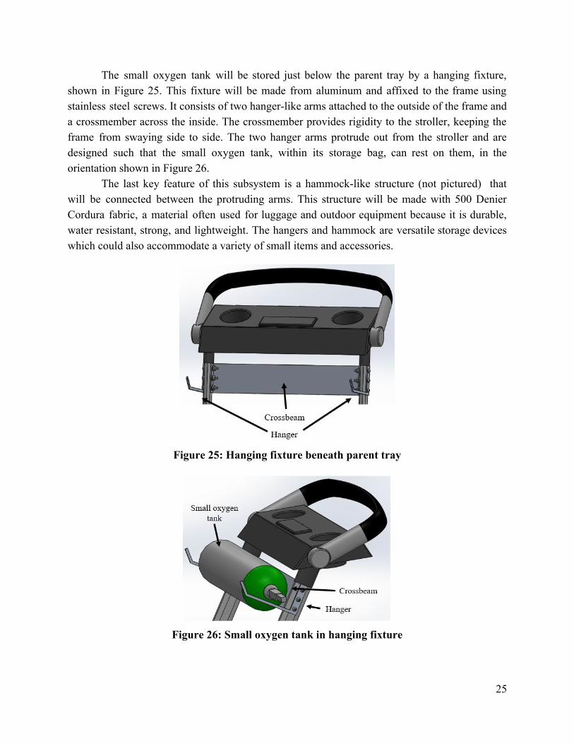
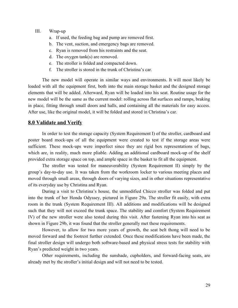
The small oxygen tank will be stored just below the parent tray by a hanging fixture, shown in Figure 25. This fixture will be made from aluminum and affixed to the frame using stainless steel screws. It consists of two hangerlike arms attached to the outside of the frame and a crossmember across the inside. The crossmember provides rigidity to the stroller, keeping the frame from swaying side to side. The two hanger arms protrude out from the stroller and are designed such that the small oxygen tank, within its storage bag, can rest on them, in the orientation shown in Figure 26.
The last key feature of this subsystem is a hammocklike structure (not pictured) that will be connected between the protruding arms. This structure will be made with 500 Denier Cordura fabric, a material often used for luggage and outdoor equipment because it is durable, water resistant, strong, and lightweight. The hangers and hammock are versatile storage devices which could also accommodate a variety of small items and accessories.
Figure 25: Hanging fixture beneath parent tray
Figure 26: Small oxygen tank in hanging fixture
25

It should be noted that the small oxygen tank will remain in its carrying case and also rest in the hammock structure (not pictured) when placed on the hooks. Therefore, the weight of the tank would not be placed on the regulator, as it appears to be in Figure 26.
5.8.3.2 Final Design for Large Oxygen Tank Storage
The large oxygen tank is only used for long trips lasting more than 6 hours. It is therefore designed to be a removable storage system, and will be removed before folding the stroller for travel. The large oxygen tank will be stored in a customized storage bag. This bag will attach to the frame through the use of two or three nylon straps. It will be sewn out of the same 500 Denier Cordura fabric as the hammock structure. The storage bag itself is shown below in Figure 27a, with the tank stored in Figure 27b, and positioned in the stroller assembly in Figure 27c.
Figure 27 (a,b,c): Storage bag, tank storage, and position in stroller assembly
The webbing straps will be attached to the carrying case and to the frame by using ITW GHook Wavelocs, as shown in Figure 28a on the next page. This strap system was selected because of its versatility. One end of the 1inch nylon attachment webbing will be fixed, and the other will be adjustable. This allows the design to apply to a variety of storage needs beyond this particular project. Three of these strap systems will be provided. The fixed loop at the end of the webbing strap will be sewn using a vertical z pattern, as shown in Figure 28b. This seam pattern was selected because it has one of the highest relative strengths [5].
26

Figure 28 (a,b): Webbing strap components and sewing specification
5.9 Bill of Materials
A shortened version of the project’s Bill of Materials is shown in Table 4. This shows the estimated cost per subsystem and the total cost of the whole project. The full Bill of Materials, including all parts and fasteners, is displayed in Appendix D.
Table 4: Condensed bill of materials
Subsystem Cost
IV Pole $14.17
Footrest $3.97*
Sliding Shelf $180.21
Small Oxygen Tank $22.22
Large Oxygen Tank $106.67
Removable Tray $39.84*
Total Cost: $367.10*
* See full Bill of Materials in Appendix D for details
27

6.0 Interfaces
The interface of each subsystem to the stroller is essential to meeting the overall system requirements. These have already been detailed and displayed in the architectural design section for each subsystem, but are reiterated here.
The IV pole will be screwed into the vertical bar of the stroller frame that connects to the back wheel of the stroller. The two pieces of the IV pole will connect with a wing screw that can be adjusted to allow it to fold for storage, which also allows the stroller to be folded.
The extended footrest will be attached much like the current footrest: around the metal rod supporting the current footrest and around the sides of the frame. The footrest also has attachments with epoxy or glue between the parts that will make up the full assembly.
The removable tray will be attached using the quickconnect feature built into the stroller. The tray itself will be shelled plastic with a space left at the connection points on both sides. Into this space, a hard plastic block will be inserted, which has a hole machined in it for the customized quickconnect piece. All of these pieces will be connected together with screws.
The sliding shelf design will have undermount drawer slides attaching directly to the basket frame at seven locations with hex bolts. The shelf itself may slide back and forth as needed on those rails, which will be located where the back seat has been removed.
The hanging fixture for the small oxygen tank will be secured with screws drilled into the stroller’s frame just below the parent tray. The large oxygen tank, in its special storage bag, will attach with Waveloc connectors and nylon webbing straps to the sides of the stroller frame.
7.0 Concept of Operations
I. Preparation a. The stroller is removed from the trunk of Christina’s car. b. The stroller is unfolded and expanded. c. The oxygen tank(s) are stored. (Whether one or both tanks are stored depends on
the duration that the stroller will be used.) d. Ryan is strapped into his seat. e. The vent, suction, and emergency bags are stored. f. If needed, the feeding bag and pump are stored.
II. Routine usage a. The stroller is pushed across flat surfaces like sidewalks and indoor floors. b. The stroller is pushed up and down ramps, like handicappedaccessible ramps
outside buildings. c. The stroller is pushed through narrow hallways, doorways, and around tight
corners. d. The stroller is stopped and locked into place when Ryan needs to be cared for. e. Stored items are accessed at a moment’s notice to care for Ryan.
28
III. Wrapup a. If used, the feeding bag and pump are removed first. b. The vent, suction, and emergency bags are removed. c. Ryan is removed from his restraints and the seat. d. The oxygen tank(s) are removed. e. The stroller is folded and compacted down. f. The stroller is stored in the trunk of Christina’s car.
The new model will operate in similar ways and environments. It will most likely be loaded with all the equipment first, both into the main storage basket and the designed storage elements that will be added. Afterward, Ryan will be loaded into his seat. Routine usage for the new model will be the same as the current model: rolling across flat surfaces and ramps, braking in place, fitting through small doors and halls, and containing all the materials for easy access. After use, like the original model, it will be folded and stored in Christina’s car.
8.0 Validate and Verify
In order to test the storage capacity (System Requirement I) of the stroller, cardboard and poster board mockups of all the equipment were created to test if the storage areas were sufficient. These mockups were imperfect since they are rigid box representations of bags, which are, in reality, much more pliable. Adding an additional cardboard mockup of the shelf provided extra storage space on top, and ample space in the basket to fit all the equipment.
The stroller was tested for maneuverability (System Requirement II) simply by the group’s daytoday use. It was taken from the workroom locker to various meeting places and moved through small areas, through doors of varying sizes, and in other situations representative of its everyday use by Christina and Ryan.
During a visit to Christina’s house, the unmodified Chicco stroller was folded and put into the trunk of her Honda Odyssey, pictured in Figure 29a. The stroller fit easily, with extra room in the trunk (System Requirement III). All additions and modifications will be designed such that they will not exceed the trunk space. The stability and comfort (System Requirement IV) of the new stroller were also tested during this visit. After fastening Ryan into his seat as shown in Figure 29b, it was found that the stroller generally met these requirements.
However, to allow for two more years of growth, the seat belt thong will need to be moved forward and the footrest further extended. Once these modifications have been made, the final stroller design will undergo both softwarebased and physical stress tests for stability with Ryan’s predicted weight in two years.
Other requirements, including the sunshade, cupholders, and forwardfacing seats, are already met by the stroller’s initial design and will not need to be tested.
29

Figure 29 (a,b): Cortina Stroller in trunk and with Ryan
After the back chair was removed and a prototype was developed of the shelf, another visit was made to Christina’s house, this time to test the shelf prototype and the total storage space on the stroller. It was also found that all the bags did fit in the stroller, even though their stiffer cardboard representations had not. The stroller is shown loaded in the preferred configuration in Figure 30 on the next page. The only component not pictured in this figure is the small oxygen tank in its bag, which will hang at the top left near the parent tray, in the same placement and position as previously shown in Figure 24.
More measurements and weights were also taken during this visit, and a few needed changes were discovered. The food bag for the IV pole was taller than expected, so the pole’s length was increased to account for this.
30
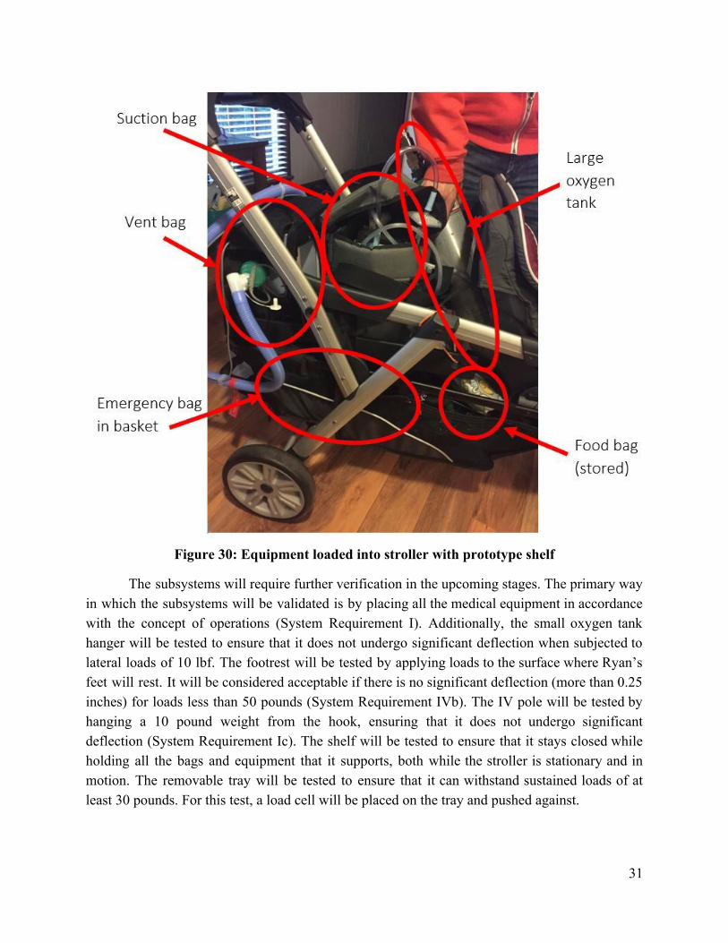
Figure 30: Equipment loaded into stroller with prototype shelf
The subsystems will require further verification in the upcoming stages. The primary way in which the subsystems will be validated is by placing all the medical equipment in accordance with the concept of operations (System Requirement I). Additionally, the small oxygen tank hanger will be tested to ensure that it does not undergo significant deflection when subjected to lateral loads of 10 lbf. The footrest will be tested by applying loads to the surface where Ryan’s feet will rest. It will be considered acceptable if there is no significant deflection (more than 0.25 inches) for loads less than 50 pounds (System Requirement IVb). The IV pole will be tested by hanging a 10 pound weight from the hook, ensuring that it does not undergo significant deflection (System Requirement Ic). The shelf will be tested to ensure that it stays closed while holding all the bags and equipment that it supports, both while the stroller is stationary and in motion. The removable tray will be tested to ensure that it can withstand sustained loads of at least 30 pounds. For this test, a load cell will be placed on the tray and pushed against.
31

9.0 Risk Management This project involves a certain amount of risk, primarily the safety concerns associated
with making modifications. Because the stroller is being made for a child, there is good reason to take seriously any risk to Ryan’s safety. Removing or modifying certain structural components of the device could lead to compromised structural integrity and possibly failure. However, with careful analysis of the structure, and welldesigned and implemented modifications, these risks will be effectively managed. Table 5 shows the most probable risks and corresponding mitigation measures. The risks and their levels are defined following the table.
Table 5: Risk Management
Risk Level Risk Expectation Risk Type Mitigation
Extremity pinching
1 Likelihood: Low Consequence: Low
Safety Proper operation training
Frame torsion 2 Likelihood: Low Consequence: Moderate
Structural Stress tests, FEA
Occupant falling out
3 Likelihood: Moderate Consequence: High
Safety Child restraints
Basket failure 4 Likelihood: Moderate Consequence: High
Structural Load distribution to the frame
Risk Levels:
Level 1: Noncritical If this risk occurs, the primary design goal can still be achieved, with minimal or temporary discomfort.
Level 2: Moderate If this risk occurs, the primary design goal is still upheld, but the occupant and/or user may have temporary injury.
Level 3: Semicritical If this risk occurs, the primary design goal has primarily failed, but may be partly recoverable. The user and/or occupant may have sustained injuries.
Level 4: Critical If this risk occurs, the primary design goal has failed and/or the user/occupant may have sustained severe injuries.
Risks: Extremity pinching: When Ryan is in his seat or when Christina is dealing with various
folding and attachment mechanisms, there is the slight chance of skin, fingers, or extremities getting pinched. In fact, this is one of the problems most discussed in the safety standards for strollers, which are further described below. However, this is a noncritical (Level 1) risk and can easily be mitigated by taking precautions.
32

Frame torsion: Because the design required removing a plastic crossbar, a chance of the aluminum frame undergoing torsion was introduced. This would be considered a moderate (Level 2) risk, and the likelihood of this scenario is low. The plastic bar did not support a great amount of load, once the second seat was removed. In addition, the small oxygen tank crossbeam and sliding shelf will provide some extra stability, functioning as support members in the back of the stroller.
Occupant falling out: If Ryan rocks back and forth in the stroller, there is a chance of him falling out, a semicritical risk (Level 3). However, this can easily be prevented with proper use of the restraint system and the quickconnect bar or tray subsystem while using the stroller.
Basket failure: The fabric making up the bottom of the stroller’s storage basket is not extremely sturdy when considering the weight of all Ryan’s equipment. If too many components are loaded directly into the basket, it could easily fail. This would be considered a critical risk (Level 4) because it means our primary design goal would have failed. This risk is addressed in our design by shifting most of the load onto the much sturdier frame of the basket and stroller, rather than the basket fabric.
According to System Requirement VIII, “The device shall meet existing standards and requirements for both strollers and disability equipment.” Research was conducted on the Americans with Disabilities Act (ADA) and Consumer Product Safety Commission (CPSC) standards [6]. It was found that ADA deals mainly with accessibility standards for public and private places for people who use disability transport devices. No product requirements were included in the ADA standards, so it was not a relevant reference for the standards sought.
The CPSC standards, however, do include information about strollers, but the full details are not publicly available and must be purchased for around $120. This did not seem like a wise use of finances, especially since the Chicco Cortina, a manufactured stroller, already met these standards beforehand. However, the changes made in March 2014 to the safety standard for carriages and strollers were available online, and showed that the primary issues involved wheels, brakes, structural integrity, and hinges. The proposed modifications on the stroller do not affect the brakes, wheels, or hinges, and no structural modifications will be made on any piece that is critical to supporting the seat or the stroller’s folding. In addition, FEA analyses and other engineering calculations have been done to verify the design’s safety and stability, indicating that the CPSC standards will not be compromised.
An institutional review board (IRB) is also being investigated. The IRB deals with experiments and research projects that involve human subjects. Since this project involves a device that will ultimately be used with a child, an IRB may need to be involved. A determination form has been submitted to Auburn University’s IRB in order to discern whether they are needed for this project, and to advise about liability forms for Christina and Ryan.
33

10.0 Technical Resource Budget Tracking
This project involves few limitations on technical resources. No parts of the stroller are powered or fueled, nor are there any electrical or memory requirements involved. The primary limitations are on the weight and volume of the device. Its weight budget should not be much greater than the Christina’s current stroller’s base weight of 33 pounds, compared to the new Chicco Cortina’s base weight of 29.5 pounds.
The weight of the new stroller will be decreased by the removal of the back seat, which weighs about 5 pounds. The added shelf system weighs about 12.5 pounds, the IV pole 0.5 pounds, and the small oxygen tank system 0.75 pounds. The footrest and large oxygen tank bag systems are made of lighter materials, making their weight negligible. The removable tray can be taken off and dealt with separately, so it is not included in the weight budget on the overall stroller. With all these weights considered, the final model comes to around 38.25 pounds, which is 5.25 pounds heavier than Christina’s current stroller. However, the subsystem additions offer vast improvements that are worth the extra weight.
To satisfy the volume requirements, the device must ultimately fit into the trunk of Christina’s car when folded. During a trip to Christina’s house, it was found that the Chicco Cortina Together left about five (when measured from the wheel’s edge) to ten inches of space in the trunk. The subsystem additions are not expected to exceed this available space, so the volume requirement will be satisfied.
11.0 Configuration Management and Documentation
Photos of equipment, bags, the house, and all important dimensions were taken at meetings with Christina and shared with the team through the organization website Basecamp. This site was also used to divide up the work and assign various tasks to team members throughout the design process. General team communication and sharing of images were done through the group messaging app GroupMe.
All of the SolidWorks CAD files were managed using a shared Google Drive folder, so that all team members could check out and modify shared assembly files. Files for the report and presentation (Google Docs, Google Slides, and Google Sheets) were also managed through this shared folder, which allowed all members to simultaneously edit, write comments, and collaborate on the documents.
12.0 Project Management
The total financial budget of this project was initially estimated to be around one thousand dollars. However, since Chicco sent a stroller at no charge, this substantially reduced the expected cost of the project. Now more of the budget can be dedicated toward other expected
34

costs, which may include the purchase of a new high chair (Appendix E), and also materials and manufacturing costs for the new stroller parts.
This first semester of the project focused only on the design and development of the modifications to the stroller. The project timeline for completed phases of the design process over the past few months is shown in the Gantt chart in Figure 31.
Figure 31: Design Gantt Chart
During the coming semester, the focus will be on fabrication and assembly of these subsystems and the overall stroller system. Some parts require machining, while others will involve different processes, like sewing and embroidery, carbon fiber molding, and vacuum plastic forming. The projected timeline for next semester is shown in a separate Gantt chart in Figure 32.
Figure 32: Fabrication Gantt Chart
13.0 Conclusions
The team is confident that the final system design meets all the mission requirements. The IV pole provides convenient placement and support for the food bag. The tray provides a sturdy space for rehabilitation exercises and a cupholder for Ryan’s use. The extended footrest provides growing room for Ryan’s feet while also protecting them from hitting wheels or the sides of the stroller. The sliding shelf provides adequate storage space and access to the basket below, while safely supporting the equipment. Both oxygen tank holders provide designated
35

locations for the tanks, as preferred by Christina, while maximizing the usable storage space. The complete system can maneuver through any doorway or hallway. No subsystem inhibits the folding action of the stroller, which allows the system to fit in Christina’s car. The team has confidence in every subsystem design—verified through FEA, engineering calculations, and technical advice— to be safe and meet the needs of Ryan and Christina.
The next step in the designbuild process is gathering the proper materials and tools to begin fabrication. Each part and component must be verified to meet design standards, and then be integrated into the respective assemblies and subsystems. With the completion and verification of the IV pole, removable tray, extended footrest, sliding shelf, and oxygen tank holders, these subsystems will be integrated into the final assembled system. Then the system requirements will be verified, and the stroller system will be will be fully demonstrated and validated to ensure that all requirements are met.
36
References [1] "Cortina Together Stroller." Chicco. n.d. Web. http://www.chiccoshop.com/gear/strollers/double/cortinatogetherstrollerombra/07079043500070.html . [2] "Best Double Stroller | Tandem Stroller | Contours." Contours Baby. n.d. Web. http://www.contoursbaby.com/products/contoursoptionselitetandemstroller/ [3] "Sit N Stand Ultra Granite." Baby Trend. n.d. Web. https://www.babytrend.com/sit_n_stand_ultra/SS66070.html [4] "DuoGlider™ Classic Connect™ Stroller." Graco Baby. n.d. Web. http://www.gracobaby.com/products/pages/duogliderclassicconnectstrollerscribbles.aspx [5] Magnussen, Cal. "How Strong is a Stitched Splice in Nylon Webbing." On Rope. n.d. Web. http://www.bethandevans.com/pdf/OnRope.pdf [6] Stevenson, Todd A. "Safety Standard for Carriages and Strollers Final Rule: 16 CFR 1112 and 1227." U.S. Consumer Product Safety Commission. U.S. CPSC, 10 Mar. 2014. Web. http://www.cpsc.gov/RegulationsLawsStandards/FederalRegisterNotices/2014/SafetyStandardforCarriagesandStrollersFinalRule/ . [7] "Knape and Vogt MUVHDB20 Knape & Vogt MUV HeavyDuty 20" (508mm) SoftClose FullExtension Undermount Drawer Slide PAIR The Hardware Hut." The Hardware Hut. n.d. Web. https://www.thehardwarehut.com/catalogproduct.php?p_ref=310874 [8] "Graco Blossom LX 4in1 Seating System." Babies 'r' Us. Toys 'r' Us, n.d. Web. www.toysrus.com/product/index.jsp?productId=68454156 . [9] "Carter's Adjustable High Chair." Babies 'r' Us. Toys 'r' Us, n.d. Web. http://www.toysrus.com/product/index.jsp?productId=80499066 .
37

Appendix A: IV Pole Calculations Bending:The dimensions of the final IV pole design (0.25” diameter rod) were drawn out
in a free body diagram, as shown in Figure 33. This was used with the design load of 5 pounds to calculate the maximum expected bending moment. This was then compared to the yield stress of the material to compute the factor of safety against bending failure in the IV pole. The factor of safety was found to be 12.7, which means that the load would have to be 63.5 pounds for bending failure to occur.
Figure 33: IV pole bending diagrams and calculations
38

Deflection: Calculations were also done for the IV pole deflection, shown in Figure 34, due to the bending moment at its end. This was done using the doubleintegration bending formulas for a beam, but turned on its side and using the equivalent moment (M=Fd) as shown in the free body diagram of Figure 33. The initial conditions—deflection ᵰ(0) and angle ᵰ’(0)—were both taken to be zero, so the constants of integration also became zero. Thus the formula simplified to the last line shown below. After plugging in the known dimensions and values, including the modulus of elasticity for steel (E=28000 ksi), the deflection at the end of the beam was found to be 0.079 inches, a negligible amount.
Figure 34: IV pole deflection calculation
39
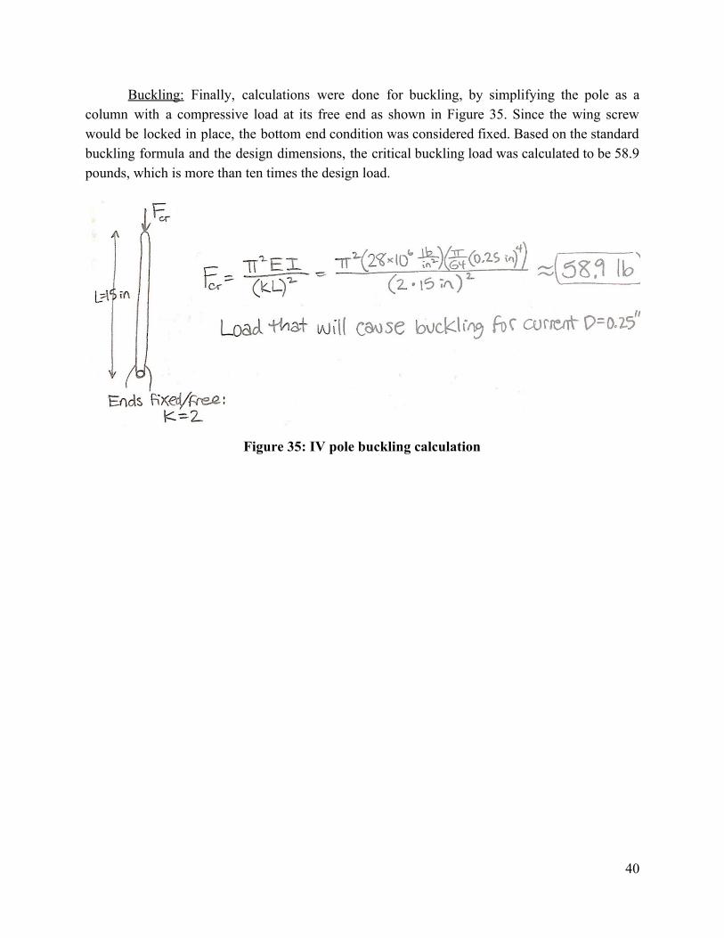
Buckling: Finally, calculations were done for buckling, by simplifying the pole as a column with a compressive load at its free end as shown in Figure 35. Since the wing screw would be locked in place, the bottom end condition was considered fixed. Based on the standard buckling formula and the design dimensions, the critical buckling load was calculated to be 58.9 pounds, which is more than ten times the design load.
Figure 35: IV pole buckling calculation
40

Appendix B: Finite Element Analysis Results
Finite element analysis (FEA) was conducted on the insert piece for the lower rear rail of the sliding shelf design. Using a simple nondestructive test, the maximum amount of force achieved (in the worstcase scenario of attempting to fold the stroller without activating the folding mechanism) was measured to be 55 lbf. Since two inserts will be supporting the rear rail, the maximum amount of force applied to each insert was found to be 110 lbf, according to the force equivalent equations shown at the bottom of this page. It is worth noting that these equations are not directly related to the free body diagram. It only shows what the equivalent force would be if the load were applied at the end of the insert (x=1 in).
Figure 36: Free body diagram of insert (cut behind holes on upper extension)
The moment equation about point O shows the calculation for the load on the member.
If the location of the force is changed, the moment must be unaffected in order to have the same effect on the inserted beam. Thus the following relationships were used to determine the force equivalent to apply to the bolts in the FEA. Subscripts 1 and 2 in the equations below denote two different locations for the application of F. Configuration 1 is when the load is at the end of the beam (stroller bar), and Configuration 2 is when it is at the end of the insert.
41

A force of 27.5 lbf was applied to each end of the two lower bolts connecting to the insert (resulting in a total 110 lbf force on the insert), and the top two bolts were held as fixed geometries. The material used for the insert and bolts was 304 stainless steel. With these conditions, the maximum stress produced was 1.430 x 10⁸ N/m2, and the maximum deformation was 0.1414 mm, as shown in Figures 37 and 38 respectively. The worstcase scenario produced a factor of safety of 1.45.
Figure 37: Stress analysis of insert at worstcase scenario
Figure 38: Deformation of insert at worstcase scenario
42

The same calculations were made for forces applied under normal conditions (F=30 lbf). This force, using the same force equivalent method, translates to 60 lbf applied directly to the insert. A force of 15 lbf was applied to each end of each of the lower four bolts. The top bolts were kept as fixed geometries. With these conditions, shown in in Figure 39, a maximum stress of 7.803 x 10⁷ N/m2 and a safety factor of 2.65 were achieved.
Figure 39: Stress analysis of insert under normal conditions
43

Appendix C: Shelf Trade Studies
Center mount drawer slides: This model of drawer slide consists of a single rail system that is located beneath the center of the drawer. These are considerably wide, and very few have full extension capability. Center mounting slides generally have a low 3550 pound capacity. Since minimizing width and having full extension were important to the system, this form were not considered. An example of these is shown below in Figure 40.
Figure 40: Center mount drawer slides
Side mount drawer slides: This slide system consists of dual rails that mount on each side of the drawer. High capacity options offer up to 500 pounds of load support, and many models of this kind have full extension, which is important to the system. Many slides of this sort are tall vertically, especially in high capacity and full extension models. This kind of slide was a good option for the stroller shelf design, thanks to their high capacity, full extension, and narrow width. Side mounting drawer slides are shown below in Figure 41.
Figure 41: Side mount drawer slides
44

Undermount drawer slides: This type of slide contains a dual rail system, which is designed to mount inside the drawer slot while supporting the drawer from beneath. This is illustrated below in Figure 42.
Figure 42: Undermount drawer slides fastening
The undermount drawer slides are designed to leave space for the drawer’s wall width, which is similar to that of the basket bar. This allows the considerable width of the slide system to be alleviated by mounting around the bar rather than inside it. These have a moderate amount of weight capacity, and most options also have full extension due to their tandem slide design. Because the slides themselves are wider than a side mount system, they may not initially seem like the best choice; however, this system can be attached around the basket in such a way to be of similar width and even smaller vertical height. This still provides more than adequate load capacity and full extension, even though the system is wider than a side mount bracket.
An example of these drawer slides is included below in Figure 43. These are the selected Knape and Vogt 20” heavyduty, softclose, fullextension, undermount drawer slides. The soft close damper system is designed to be easily removable if it is not deemed beneficial for this application [7].
Figure 43: Knape and Vogt undermount drawer slides
45

Appendix D: Full Bill of Materials The parts in the Bill of Materials use a naming scheme related to the manufactured
subsystem that they are associated with. It includes initials for the subsystem (IV stands for IV pole, FR for footrest, SS for sliding shelf, OS for small oxygen tank storage, OL for large oxygen tank storage, and TR for removable tray.) and a number for each part.
As noted in the table, there are parts in the footrest list that are yet to be finalized. In a meeting with Jeff Thompson, it was determined that price would be discussed in detail with Dr. Beale upon material selection. Therefore, the quantity and prices for the carbon fiber and foam are currently left blank. There is a similar case with the vacuum mold pattern for the removable tray, since the group is also waiting to hear back from David Gowan with a more definitive price for molding.
Table 6: Full bill of materials
46

47

Appendix E: High Chair
In addition to the stroller, Christina may be in need of a better, more stable high chair. Her current setup at home consists of either a booster seat on top of a regular chair or a smaller stroller with its wheels locked. The booster seat is at risk of tipping over when Ryan rocks backward, and the stroller is far too bulky and cumbersome. The new high chair would also require a table large enough to accommodate Ryan’s rehabilitation activities. The high chair is currently a small side project that is much more basic than the stroller.
For the high chair, the mission objective is to provide a chair that is stable against rocking, mobile, and provides adequate table space for rehabilitation activities.
System Requirements I. The device shall eliminate the risk of the child rocking or tipping over.
a. The wheels shall have a locking system for stabilization. II. The device shall accommodate two years of growth from the child.
a. The device shall support the child’s weight for two years of growth. b. The device’s height shall be adjustable.
III. The device shall include a large removable tray for rehabilitation and other activities. IV. The device’s dimensions shall be compatible with the house dimensions and kitchen
counter height. V. The device shall be easily foldable for storage. VI. The device shall be easily transportable by rolling, while in use or folded.
Two alternative high chair options were found that meet these requirements. The first is the Graco Blossom LX [8], shown in Figure 42 on the next page. This high chair can support a weight of 60 pounds, which is greater than Ryan’s estimated 50pound weight in two years. This high load capacity, in addition to the chair’s sturdy setup, will allow it to withstand any rocking force Ryan provides. It also provides many options for height, recline, seat arrangement, and footrest position, which would would allow more versatility as Ryan grows. This model also has wheels, as well as an extra storage space under the seat that may be useful. The Graco Blossom LX costs $189.99, which will most likely be affordable with the amount of budget remaining.
48

Figure 42: Graco Blossom LX
The second option is the Carter’s Adjustable High Chair [9], shown below in Figure 43. This chair’s weight limit is 50 pounds, which means it will just support Ryan’s expected weight in two years. Like the first model, it also has plenty of different position options for the height, recline, and tray; however, it offers no adjustability in the seat or footrest. This chair costs $99.99, which is less than the Graco Blossom, although either one can be afforded.
Figure 43: Carter’s adjustable high chair
Once the stroller cost has been finalized and the remaining funds determined, one of these high chairs will be chosen and ordered. Modifications may be made if deemed necessary.
49

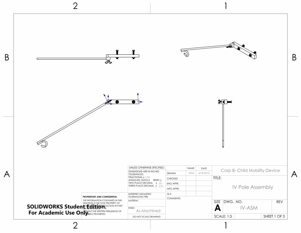
Appendix F: Detailed Design Drawings
1. IV Pole (IV##) 2. Removable Tray (TR##) 3. Extended Footrest (FR##) 4. Sliding Shelf (SS##) 5. Small Oxygen Tank Storage (OS##) 6. Large Oxygen Tank Storage (OL##)
50
UNLESS OTHERWISE SPECIFIED:
CHECKED
SIZE
TITLE:
PROPRIETARY AND CONFIDENTIALINTERPRET GEOMETRICTOLERANCING PER:
Q.A.
FINISH
DWG. NO.
DATE
A
DIMENSIONS ARE IN INCHESTOLERANCES:FRACTIONALANGULAR: MACH BEND TWO PLACE DECIMAL THREE PLACE DECIMAL
MATERIAL
NAME
REV
DO NOT SCALE DRAWING SCALE: 1:5
ENG APPR.
THE INFORMATION CONTAINED IN THISDRAWING IS THE SOLE PROPERTY OFCORP 8. ANY REPRODUCTION IN PART OR AS A WHOLEWITHOUT THE WRITTEN PERMISSION OFCORP 8 IS PROHIBITED.
COMMENTS:
DRAWN
MFG APPR.
SHEET 1 OF 3
2 1
A
B
A
B
12
Corp 8- Child Mobility Device
As Machined
.010
.05
1/32
IV Pole Assembly
IV-ASM
NDM 4/18/2016
SOLIDWORKS Student Edition. For Academic Use Only.

R0.
375
0.250
0.
563
0.
563
0.563
0.56
3
6.000
5.625
0.500
UNLESS OTHERWISE SPECIFIED:
CHECKED
SIZE
TITLE:
PROPRIETARY AND CONFIDENTIALINTERPRET GEOMETRICTOLERANCING PER:
Q.A.
FINISH
DWG. NO.
DATE
A
DIMENSIONS ARE IN INCHESTOLERANCES:FRACTIONALANGULAR: MACH BEND TWO PLACE DECIMAL THREE PLACE DECIMAL
MATERIAL
NAME
REV
DO NOT SCALE DRAWING SCALE: 1:1
ENG APPR.
THE INFORMATION CONTAINED IN THISDRAWING IS THE SOLE PROPERTY OFCORP 8. ANY REPRODUCTION IN PART OR AS A WHOLEWITHOUT THE WRITTEN PERMISSION OFCORP 8 IS PROHIBITED.
COMMENTS:
DRAWN
MFG APPR.
SHEET 2 OF 3
2 1
A
B
A
B
12
Corp 8- Child Mobility Device
As Machined
.010
.05
1/32
6061 Aluminum
IV Pole Base
4/18/2016NDM
IV-01SOLIDWORKS Student Edition. For Academic Use Only.

0.750
R0.375
R0.
625
0.500
15.375
0.
250
14.625
UNLESS OTHERWISE SPECIFIED:
CHECKED
SIZE
TITLE:
PROPRIETARY AND CONFIDENTIALINTERPRET GEOMETRICTOLERANCING PER:
Q.A.
FINISH
DWG. NO.
DATE
A
DIMENSIONS ARE IN INCHESTOLERANCES:FRACTIONALANGULAR: MACH BEND TWO PLACE DECIMAL THREE PLACE DECIMAL
MATERIAL
NAME
REV
DO NOT SCALE DRAWING SCALE: 1:3
ENG APPR.
THE INFORMATION CONTAINED IN THISDRAWING IS THE SOLE PROPERTY OFCORP 8. ANY REPRODUCTION IN PART OR AS A WHOLEWITHOUT THE WRITTEN PERMISSION OFCORP 8 IS PROHIBITED.
COMMENTS:
DRAWN
MFG APPR.
SHEET 3 OF 3
2 1
A
B
A
B
12
Corp 8- Child Mobility Device
As Machined
.010
.05
1/32
6061 AluminumIV-02
IV Pole
NDM
4/18/2016
4/18/2016
SOLIDWORKS Student Edition. For Academic Use Only.
A
DETAIL ASCALE 1 : 2
1
4
3
2
5
ITEM NO. PART NUMBER DESCRIPTION QTY.1 TR-03 Molded Tray 12 TR-02 Connector Block (Right shown) 1
3 TR-06 Flanged SS Button Head 1/4-20, 3/4 lg 4
4 TR-05 18-8 SS 4-40 Machine screw, 7/8th lg 2
5 TR-04 Quick Connector 1
UNLESS OTHERWISE SPECIFIED:
CHECKED
SIZE
TITLE:
PROPRIETARY AND CONFIDENTIALINTERPRET GEOMETRICTOLERANCING PER:
Q.A.
FINISH
DWG. NO.
DATE
A
DIMENSIONS ARE IN INCHESTOLERANCES:FRACTIONALANGULAR: MACH BEND TWO PLACE DECIMAL THREE PLACE DECIMAL
MATERIAL
NAME
REV
DO NOT SCALE DRAWING SCALE: 1:7
ENG APPR.
THE INFORMATION CONTAINED IN THISDRAWING IS THE SOLE PROPERTY OFCORP 8. ANY REPRODUCTION IN PART OR AS A WHOLEWITHOUT THE WRITTEN PERMISSION OFCORP 8 IS PROHIBITED.
COMMENTS:
DRAWN
MFG APPR.
SHEET 1 OF 6
2 1
A
B
A
B
12
Corp 8- Child Mobility Device
Tray Assembly
As Machined
.010
.05
1/32
4/27/2016JHG
TR-ASMSOLIDWORKS Student Edition. For Academic Use Only.

1.5
00
2.0
00
16.500
14.
000
3.000
1.250
14.000
R2.000
CC 84°
2.3
75
SECTION C-C
All edges are machined to 1/4" fillet
UNLESS OTHERWISE SPECIFIED:
CHECKED
SIZE
TITLE:
PROPRIETARY AND CONFIDENTIALINTERPRET GEOMETRICTOLERANCING PER:
Q.A.
FINISH
DWG. NO.
DATE
A
DIMENSIONS ARE IN INCHESTOLERANCES:FRACTIONALANGULAR: MACH BEND TWO PLACE DECIMAL THREE PLACE DECIMAL
MATERIAL
NAME
REV
DO NOT SCALE DRAWING SCALE: 1:6
ENG APPR.
THE INFORMATION CONTAINED IN THISDRAWING IS THE SOLE PROPERTY OFCORP 8. ANY REPRODUCTION IN PART OR AS A WHOLEWITHOUT THE WRITTEN PERMISSION OFCORP 8 IS PROHIBITED.
COMMENTS:
DRAWN
MFG APPR.
SHEET 2 OF 6
2 1
A
B
A
B
12
Corp 8- Child Mobility Device
MDF
Tray Mold
4/27/2016JHG
TRM-03As Machined
.010
.05
1/32
SOLIDWORKS Student Edition. For Academic Use Only.

A
1.250 0.500
0.672 1.169
0 0.500 0.750 1.320 1.372
DETAIL ASCALE 1 : 2
This is the resulting vacuumformed positive from the mold.
UNLESS OTHERWISE SPECIFIED:
CHECKED
SIZE
TITLE:
PROPRIETARY AND CONFIDENTIALINTERPRET GEOMETRICTOLERANCING PER:
Q.A.
FINISH
DWG. NO.
DATE
A
DIMENSIONS ARE IN INCHESTOLERANCES:FRACTIONALANGULAR: MACH BEND TWO PLACE DECIMAL THREE PLACE DECIMAL
MATERIAL
NAME
REV
DO NOT SCALE DRAWING SCALE: 1:7
ENG APPR.
THE INFORMATION CONTAINED IN THISDRAWING IS THE SOLE PROPERTY OFCORP 8. ANY REPRODUCTION IN PART OR AS A WHOLEWITHOUT THE WRITTEN PERMISSION OFCORP 8 IS PROHIBITED.
COMMENTS:
DRAWN
MFG APPR.
SHEET 3 OF 6
2 1
A
B
A
B
12
Corp 8- Child Mobility Device
ABS
Tray For Model
4/27/2016JHG
TR-03As Machined
.010
.05
1/32
SOLIDWORKS Student Edition. For Academic Use Only.

0.
402
0.
500
0.175 THRU 2 PLCS
0
0.375
0.875
2.600
0.200 THRU
0
1.6
70
2.6
00
UNLESS OTHERWISE SPECIFIED:
CHECKED
SIZE
TITLE:
PROPRIETARY AND CONFIDENTIALINTERPRET GEOMETRICTOLERANCING PER:
Q.A.
FINISH
DWG. NO.
DATE
A
DIMENSIONS ARE IN INCHESTOLERANCES:FRACTIONALANGULAR: MACH BEND TWO PLACE DECIMAL THREE PLACE DECIMAL
MATERIAL
NAME
REV
DO NOT SCALE DRAWING SCALE: 1:1
ENG APPR.
THE INFORMATION CONTAINED IN THISDRAWING IS THE SOLE PROPERTY OFCORP 8. ANY REPRODUCTION IN PART OR AS A WHOLEWITHOUT THE WRITTEN PERMISSION OFCORP 8 IS PROHIBITED.
COMMENTS:
DRAWN
MFG APPR.
SHEET 4 OF 6
2 1
A
B
A
B
12
Corp 8- Child Mobility Device
As Machined
.010
.05
1/32
Connector Pin
TR-04
JHG 4/27/2016
4130 AlloySOLIDWORKS Student Edition. For Academic Use Only.

0.283 1.000
0.500
0.3
75
1.250 1
.750
1.5
61
84°
0.
500
0.203 THRU2 PLCS
0.2502 PLCS
0.089 0.2502 PLCS
0
0.5
00
1.2
50
1.7
50
0
0.5
25
1.0
25
1.4
00
UNLESS OTHERWISE SPECIFIED:
CHECKED
SIZE
TITLE:
PROPRIETARY AND CONFIDENTIALINTERPRET GEOMETRICTOLERANCING PER:
Q.A.
FINISH
DWG. NO.
DATE
A
DIMENSIONS ARE IN INCHESTOLERANCES:FRACTIONALANGULAR: MACH BEND TWO PLACE DECIMAL THREE PLACE DECIMAL
MATERIAL
NAME
REV
DO NOT SCALE DRAWING SCALE: 1:1
ENG APPR.
THE INFORMATION CONTAINED IN THISDRAWING IS THE SOLE PROPERTY OFCORP 8. ANY REPRODUCTION IN PART OR AS A WHOLEWITHOUT THE WRITTEN PERMISSION OFCORP 8 IS PROHIBITED.
COMMENTS:
DRAWN
MFG APPR.
SHEET 5 OF 6
2 1
A
B
A
B
12
Corp 8- Child Mobility Device
Delrin 2700 NC010, Low Viscosity Acetal Copolymer (SS)
Tray Connector Block -Left
4/27/2016JHG
As Machined
.010
.05
1/32
SOLIDWORKS Student Edition. For Academic Use Only.

0.
500
1.000 0.283
0.3
75
0.500
84°
0.500
0.203 THRU2 PLCS
0.2502 PLCS
0.089 0.2502 PLCS
0
0.5
00
1.2
50
1.7
50
0
0.525
1.025
1.400 1.250 1
.750
1.5
61
UNLESS OTHERWISE SPECIFIED:
CHECKED
SIZE
TITLE:
PROPRIETARY AND CONFIDENTIALINTERPRET GEOMETRICTOLERANCING PER:
Q.A.
FINISH
DWG. NO.
DATE
A
DIMENSIONS ARE IN INCHESTOLERANCES:FRACTIONALANGULAR: MACH BEND TWO PLACE DECIMAL THREE PLACE DECIMAL
MATERIAL
NAME
REV
DO NOT SCALE DRAWING SCALE: 1:1
ENG APPR.
THE INFORMATION CONTAINED IN THISDRAWING IS THE SOLE PROPERTY OFCORP 8. ANY REPRODUCTION IN PART OR AS A WHOLEWITHOUT THE WRITTEN PERMISSION OFCORP 8 IS PROHIBITED.
COMMENTS:
DRAWN
MFG APPR.
SHEET 6 OF 6
2 1
A
B
A
B
12
Corp 8- Child Mobility Device
Delrin 2700 NC010, Low Viscosity Acetal Copolymer (SS)
Tray Connector Block- Right
4/27/2016JHG
TR-02As Machined
.010
.05
1/32
SOLIDWORKS Student Edition. For Academic Use Only.

1
2
3
*All thicknesses for this assembly are subject to change based on material selection
ITEM NO.
PART NUMBER DESCRIPTION QTY.
1 FR_01 Footrest Base 1
2 FR_02 Footrest Sidewall 23 FR_03 Footrest Grip 2
UNLESS OTHERWISE SPECIFIED:
CHECKED
SIZE
TITLE:
PROPRIETARY AND CONFIDENTIALINTERPRET GEOMETRICTOLERANCING PER:
Q.A.
FINISH
DWG. NO.
DATE
A
DIMENSIONS ARE IN INCHESTOLERANCES:FRACTIONALANGULAR: MACH BEND TWO PLACE DECIMAL THREE PLACE DECIMAL
MATERIAL
NAME
REV
DO NOT SCALE DRAWING SCALE: 1:5
ENG APPR.
THE INFORMATION CONTAINED IN THISDRAWING IS THE SOLE PROPERTY OFCORP 8. ANY REPRODUCTION IN PART OR AS A WHOLEWITHOUT THE WRITTEN PERMISSION OFCORP 8 IS PROHIBITED.
COMMENTS:
DRAWN
MFG APPR.
SHEET 1 OF 6
2 1
A
B
A
B
12
Corp 8- Child Mobility Device
Carbon Fiber
4/25/2016DTF
FR-ASMAs Machined
.010
.05
1/32
SOLIDWORKS Student Edition. For Academic Use Only.

6.000
R0.440
0.2
00
14.500
14.250
UNLESS OTHERWISE SPECIFIED:
CHECKED
SIZE
TITLE:
PROPRIETARY AND CONFIDENTIALINTERPRET GEOMETRICTOLERANCING PER:
Q.A.
FINISH
DWG. NO.
DATE
A
DIMENSIONS ARE IN INCHESTOLERANCES:FRACTIONALANGULAR: MACH BEND TWO PLACE DECIMAL THREE PLACE DECIMAL
MATERIAL
NAME
REV
DO NOT SCALE DRAWING SCALE: 1:5
ENG APPR.
THE INFORMATION CONTAINED IN THISDRAWING IS THE SOLE PROPERTY OFCORP 8. ANY REPRODUCTION IN PART OR AS A WHOLEWITHOUT THE WRITTEN PERMISSION OFCORP 8 IS PROHIBITED.
COMMENTS:
DRAWN
MFG APPR.
SHEET 2 OF 6
2 1
A
B
A
B
12
Corp 8- Child Mobility Device
Carbon Fiber
Footrest Base
4/26/2016DTF
FR-01As Machined
.010
.05
1/32
SOLIDWORKS Student Edition. For Academic Use Only.

6.000
R0.445
0.7
50
3.500
146°
111°
0.200 4
.690
UNLESS OTHERWISE SPECIFIED:
CHECKED
SIZE
TITLE:
PROPRIETARY AND CONFIDENTIALINTERPRET GEOMETRICTOLERANCING PER:
Q.A.
FINISH
DWG. NO.
DATE
A
DIMENSIONS ARE IN INCHESTOLERANCES:FRACTIONALANGULAR: MACH BEND TWO PLACE DECIMAL THREE PLACE DECIMAL
MATERIAL
NAME
REV
DO NOT SCALE DRAWING SCALE: 1:2
ENG APPR.
THE INFORMATION CONTAINED IN THISDRAWING IS THE SOLE PROPERTY OFCORP 8. ANY REPRODUCTION IN PART OR AS A WHOLEWITHOUT THE WRITTEN PERMISSION OFCORP 8 IS PROHIBITED.
COMMENTS:
DRAWN
MFG APPR.
SHEET 3 OF 6
2 1
A
B
A
B
12
Corp 8- Child Mobility Device
Carbon Fiber
Footrest Sidewall
4/26/2016DTF
FR-02As Machined
.010
.05
1/32
SOLIDWORKS Student Edition. For Academic Use Only.

0.400
0.720
1.1
60
0.7
50
0.200 3.750
UNLESS OTHERWISE SPECIFIED:
CHECKED
SIZE
TITLE:
PROPRIETARY AND CONFIDENTIALINTERPRET GEOMETRICTOLERANCING PER:
Q.A.
FINISH
DWG. NO.
DATE
A
DIMENSIONS ARE IN INCHESTOLERANCES:FRACTIONALANGULAR: MACH BEND TWO PLACE DECIMAL THREE PLACE DECIMAL
MATERIAL
NAME
REV
DO NOT SCALE DRAWING SCALE: 1:1
ENG APPR.
THE INFORMATION CONTAINED IN THISDRAWING IS THE SOLE PROPERTY OFCORP 8. ANY REPRODUCTION IN PART OR AS A WHOLEWITHOUT THE WRITTEN PERMISSION OFCORP 8 IS PROHIBITED.
COMMENTS:
DRAWN
MFG APPR.
SHEET 4 OF 6
2 1
A
B
A
B
12
Corp 8- Child Mobility Device
Carbon Fiber
Footrest Grip
4/26/2016DTF
FR-03As Machined
.010
.05
1/32
SOLIDWORKS Student Edition. For Academic Use Only.

0.880
16.000
UNLESS OTHERWISE SPECIFIED:
CHECKED
SIZE
TITLE:
PROPRIETARY AND CONFIDENTIALINTERPRET GEOMETRICTOLERANCING PER:
Q.A.
FINISH
DWG. NO.
DATE
A
DIMENSIONS ARE IN INCHESTOLERANCES:FRACTIONALANGULAR: MACH BEND TWO PLACE DECIMAL THREE PLACE DECIMAL
MATERIAL
NAME
REV
DO NOT SCALE DRAWING SCALE: 2:1
ENG APPR.
THE INFORMATION CONTAINED IN THISDRAWING IS THE SOLE PROPERTY OFCORP 8. ANY REPRODUCTION IN PART OR AS A WHOLEWITHOUT THE WRITTEN PERMISSION OFCORP 8 IS PROHIBITED.
COMMENTS:
DRAWN
MFG APPR.
SHEET 5 OF 6
2 1
A
B
A
B
12
Corp 8- Child Mobility Device
Wood
Footrest Base Mold
4/26/2017DTF
FRM-01As Machined
.010
.05
1/32
SOLIDWORKS Student Edition. For Academic Use Only.

1.7
50
2.1
60
0.400
0.720 10.000
UNLESS OTHERWISE SPECIFIED:
CHECKED
SIZE
TITLE:
PROPRIETARY AND CONFIDENTIALINTERPRET GEOMETRICTOLERANCING PER:
Q.A.
FINISH
DWG. NO.
DATE
A
DIMENSIONS ARE IN INCHESTOLERANCES:FRACTIONALANGULAR: MACH BEND TWO PLACE DECIMAL THREE PLACE DECIMAL
MATERIAL
NAME
REV
DO NOT SCALE DRAWING SCALE: 1:1
ENG APPR.
THE INFORMATION CONTAINED IN THISDRAWING IS THE SOLE PROPERTY OFCORP 8. ANY REPRODUCTION IN PART OR AS A WHOLEWITHOUT THE WRITTEN PERMISSION OFCORP 8 IS PROHIBITED.
COMMENTS:
DRAWN
MFG APPR.
SHEET 6 OF 6
2 1
A
B
A
B
12
Corp 8- Child Mobility Device
Wood
Footrest Grip Mold
4/26/2016DTF
FRM-03As Machined
.010
.05
1/32
SOLIDWORKS Student Edition. For Academic Use Only.

2
5
3
4
1
ITEM NO. PART NUMBER DESCRIPTION QTY.
1 SS-09 Frame On Stroller 2
2 SS-02 Removable Rear Basket Frame 1
3 SS-08 Insert to Lower Rear Basket 2
4 SS-06 Hex Bolt 1"x1/4" 185 SS-07 Locking Hex Nut 1/4" 18
UNLESS OTHERWISE SPECIFIED:
CHECKED
SIZE
TITLE:
PROPRIETARY AND CONFIDENTIALINTERPRET GEOMETRICTOLERANCING PER:
Q.A.
FINISH
DWG. NO.
DATE
A
DIMENSIONS ARE IN INCHESTOLERANCES:FRACTIONALANGULAR: MACH BEND TWO PLACE DECIMAL THREE PLACE DECIMAL
MATERIAL
NAME
REV
DO NOT SCALE DRAWING SCALE: 1:8
ENG APPR.
THE INFORMATION CONTAINED IN THISDRAWING IS THE SOLE PROPERTY OFCORP 8. ANY REPRODUCTION IN PART OR AS A WHOLEWITHOUT THE WRITTEN PERMISSION OFCORP 8 IS PROHIBITED.
COMMENTS:
DRAWN
MFG APPR.
SHEET 1 OF 4
2 1
A
B
A
B
12
Corp 8- Child Mobility Device
Basket Rail Assembly
4/28/2016NDG
SS-ASM-01As Machined
.010
.05
1/32
SOLIDWORKS Student Edition. For Academic Use Only.

0
3.375
Cut thru all
0.250 THRU @ 10PLCS
0
3.0
00
9.0
00
3.3
75
3.8
75
4.5
63
5.8
13
2.4
50
Cut thru all
UNLESS OTHERWISE SPECIFIED:
CHECKED
SIZE
TITLE:
PROPRIETARY AND CONFIDENTIALINTERPRET GEOMETRICTOLERANCING PER:
Q.A.
FINISH
DWG. NO.
DATE
A
DIMENSIONS ARE IN INCHESTOLERANCES:FRACTIONALANGULAR: MACH BEND TWO PLACE DECIMAL THREE PLACE DECIMAL
MATERIAL
NAME
REV
DO NOT SCALE DRAWING SCALE: 1:3
ENG APPR.
THE INFORMATION CONTAINED IN THISDRAWING IS THE SOLE PROPERTY OFCORP 8. ANY REPRODUCTION IN PART OR AS A WHOLEWITHOUT THE WRITTEN PERMISSION OFCORP 8 IS PROHIBITED.
COMMENTS:
DRAWN
MFG APPR.
SHEET 2 OF 4
2 1
A
B
A
B
12
Corp 8- Child Mobility Device
AISI 1020 Steel, Cold Rolled
End of Basket Rail
4/25/2016NDG
SS-08As Machined
.010
.05
1/32
SOLIDWORKS Student Edition. For Academic Use Only.

0.250 THRU @ 4PLCS
0
0.2
75
0.8
25
1.7
00
2.0
75
2.7
63
3.0
00
0 0.200 0.400
1.250 1.450 1.650
1.2
00
0.300
UNLESS OTHERWISE SPECIFIED:
CHECKED
SIZE
TITLE:
PROPRIETARY AND CONFIDENTIALINTERPRET GEOMETRICTOLERANCING PER:
Q.A.
FINISH
DWG. NO.
DATE
A
DIMENSIONS ARE IN INCHESTOLERANCES:FRACTIONALANGULAR: MACH BEND TWO PLACE DECIMAL THREE PLACE DECIMAL
MATERIAL
NAME
REV
DO NOT SCALE DRAWING SCALE: 1.5:1
ENG APPR.
THE INFORMATION CONTAINED IN THISDRAWING IS THE SOLE PROPERTY OFCORP 8. ANY REPRODUCTION IN PART OR AS A WHOLEWITHOUT THE WRITTEN PERMISSION OFCORP 8 IS PROHIBITED.
COMMENTS:
DRAWN
MFG APPR.
SHEET 3 OF 4
2 1
A
B
A
B
12
Corp 8- Child Mobility Device
AISI 304
Insert to Lower Rear Rail
4/26/2016NDG
SS-02As Machined
.010
.05
1/32
SOLIDWORKS Student Edition. For Academic Use Only.

0.250 THRU @ 4PLCS
0
3.7
81
4.4
69
11.
344
12.
031
This is the connection endfor the rear basket rail, SS-01
UNLESS OTHERWISE SPECIFIED:
CHECKED
SIZE
TITLE:
PROPRIETARY AND CONFIDENTIALINTERPRET GEOMETRICTOLERANCING PER:
Q.A.
FINISH
DWG. NO.
DATE
A
DIMENSIONS ARE IN INCHESTOLERANCES:FRACTIONALANGULAR: MACH BEND TWO PLACE DECIMAL THREE PLACE DECIMAL
MATERIAL
NAME
REV
DO NOT SCALE DRAWING SCALE: 1:2
ENG APPR.
THE INFORMATION CONTAINED IN THISDRAWING IS THE SOLE PROPERTY OFCORP 8. ANY REPRODUCTION IN PART OR AS A WHOLEWITHOUT THE WRITTEN PERMISSION OFCORP 8 IS PROHIBITED.
COMMENTS:
DRAWN
MFG APPR.
SHEET 4 OF 4
2 1
A
B
A
B
12
Corp 8- Child Mobility Device
AISI 1020 Steel, Cold Rolled
Side Rail for Basket
4/26/2016NDG
SS-09As Machined
.010
.05
1/32
SOLIDWORKS Student Edition. For Academic Use Only.

0.125
0.750
5.500
135°
1.50
0
0.250
0.250 THRU3 PLCS
0 0.500
1.500
2.500 3.000
UNLESS OTHERWISE SPECIFIED:
CHECKED
SIZE
TITLE:
PROPRIETARY AND CONFIDENTIALINTERPRET GEOMETRICTOLERANCING PER:
Q.A.
FINISH
DWG. NO.
DATE
A
DIMENSIONS ARE IN INCHESTOLERANCES:FRACTIONALANGULAR: MACH BEND TWO PLACE DECIMAL THREE PLACE DECIMAL
MATERIAL
NAME
REV
DO NOT SCALE DRAWING SCALE: 1:2
ENG APPR.
THE INFORMATION CONTAINED IN THISDRAWING IS THE SOLE PROPERTY OFCORP 8. ANY REPRODUCTION IN PART OR AS A WHOLEWITHOUT THE WRITTEN PERMISSION OFCORP 8 IS PROHIBITED.
COMMENTS:
DRAWN
MFG APPR.
SHEET 1 OF 2
2 1
A
B
A
B
12
Corp 8- Child Mobility Device
6061 Alloy
Small O2 Hanger
4/24/2016JHG
OS-1As Machined
.010
.05
1/32
SOLIDWORKS Student Edition. For Academic Use Only.

16.000
3.0
00
0.125
0.6
25
0.7
50
0.250 THRU 6 PLCS
0 0.500
1.500
2.500 3.000
UNLESS OTHERWISE SPECIFIED:
CHECKED
SIZE
TITLE:
PROPRIETARY AND CONFIDENTIALINTERPRET GEOMETRICTOLERANCING PER:
Q.A.
FINISH
DWG. NO.
DATE
A
DIMENSIONS ARE IN INCHESTOLERANCES:FRACTIONALANGULAR: MACH BEND TWO PLACE DECIMAL THREE PLACE DECIMAL
MATERIAL
NAME
REV
DO NOT SCALE DRAWING SCALE: 1:2
ENG APPR.
THE INFORMATION CONTAINED IN THISDRAWING IS THE SOLE PROPERTY OFCORP 8. ANY REPRODUCTION IN PART OR AS A WHOLEWITHOUT THE WRITTEN PERMISSION OFCORP 8 IS PROHIBITED.
COMMENTS:
DRAWN
MFG APPR.
SHEET 2 OF 2
2 1
A
B
A
B
12
Corp 8- Child Mobility Device
6061 Alloy
Small O2 Crossbeam
4/24/2016JHG
OS-02As Machined
.010
.05
1/32
SOLIDWORKS Student Edition. For Academic Use Only.

1
3
4
Straight seam
Straight seam top and bottom
2
*All internal seams are straight and bound
ITEM NO. PART NUMBER DESCRIPTION QTY.
1 OL-1 Large Cylinder 12 OL-2 Large 02 Base 13 OL-3 Reinforcement Strip 14 OL-4 Daisy Chain 3
UNLESS OTHERWISE SPECIFIED:
CHECKED
SIZE
TITLE:
PROPRIETARY AND CONFIDENTIALINTERPRET GEOMETRICTOLERANCING PER:
Q.A.
FINISH
DWG. NO.
DATE
A
DIMENSIONS ARE IN INCHESTOLERANCES:FRACTIONALANGULAR: MACH BEND TWO PLACE DECIMAL THREE PLACE DECIMAL
MATERIAL
NAME
REV
DO NOT SCALE DRAWING SCALE: 1:5
ENG APPR.
THE INFORMATION CONTAINED IN THISDRAWING IS THE SOLE PROPERTY OFCORP 8. ANY REPRODUCTION IN PART OR AS A WHOLEWITHOUT THE WRITTEN PERMISSION OFCORP 8 IS PROHIBITED.
COMMENTS:
DRAWN
MFG APPR.
SHEET 1 OF 6
2 1
A
B
A
B
12
Corp 8- Child Mobility Device
Cordura, Webbing
Large 02 Bag
4/25/2016DTF
OL-ASMAs Machined
.010
.05
1/32
SOLIDWORKS Student Edition. For Academic Use Only.

18.
000
15.000
UNLESS OTHERWISE SPECIFIED:
CHECKED
SIZE
TITLE:
PROPRIETARY AND CONFIDENTIALINTERPRET GEOMETRICTOLERANCING PER:
Q.A.
FINISH
DWG. NO.
DATE
A
DIMENSIONS ARE IN INCHESTOLERANCES:FRACTIONALANGULAR: MACH BEND TWO PLACE DECIMAL THREE PLACE DECIMAL
MATERIAL
NAME
REV
DO NOT SCALE DRAWING SCALE: 1:5
ENG APPR.
THE INFORMATION CONTAINED IN THISDRAWING IS THE SOLE PROPERTY OFCORP 8. ANY REPRODUCTION IN PART OR AS A WHOLEWITHOUT THE WRITTEN PERMISSION OFCORP 8 IS PROHIBITED.
COMMENTS:
DRAWN
MFG APPR.
SHEET 2 OF 6
2 1
A
B
A
B
12
Corp 8- Child Mobility Device
500D Cordura
Cloth Cylinder Cutout
4/25/2016DTF
OL-01As Machined
.010
.05
1/32
SOLIDWORKS Student Edition. For Academic Use Only.
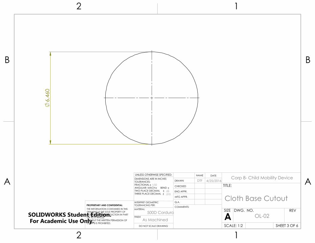
6.
460
UNLESS OTHERWISE SPECIFIED:
CHECKED
SIZE
TITLE:
PROPRIETARY AND CONFIDENTIALINTERPRET GEOMETRICTOLERANCING PER:
Q.A.
FINISH
DWG. NO.
DATE
A
DIMENSIONS ARE IN INCHESTOLERANCES:FRACTIONALANGULAR: MACH BEND TWO PLACE DECIMAL THREE PLACE DECIMAL
MATERIAL
NAME
REV
DO NOT SCALE DRAWING SCALE: 1:2
ENG APPR.
THE INFORMATION CONTAINED IN THISDRAWING IS THE SOLE PROPERTY OFCORP 8. ANY REPRODUCTION IN PART OR AS A WHOLEWITHOUT THE WRITTEN PERMISSION OFCORP 8 IS PROHIBITED.
COMMENTS:
DRAWN
MFG APPR.
SHEET 3 OF 6
2 1
A
B
A
B
12
Corp 8- Child Mobility Device
500D Cordura
Cloth Base Cutout
4/25/2016DTF
OL-02As Machined
.010
.05
1/32
SOLIDWORKS Student Edition. For Academic Use Only.

15.000
4.0
00
UNLESS OTHERWISE SPECIFIED:
CHECKED
SIZE
TITLE:
PROPRIETARY AND CONFIDENTIALINTERPRET GEOMETRICTOLERANCING PER:
Q.A.
FINISH
DWG. NO.
DATE
A
DIMENSIONS ARE IN INCHESTOLERANCES:FRACTIONALANGULAR: MACH BEND TWO PLACE DECIMAL THREE PLACE DECIMAL
MATERIAL
NAME
REV
DO NOT SCALE DRAWING SCALE: 1:2
ENG APPR.
THE INFORMATION CONTAINED IN THISDRAWING IS THE SOLE PROPERTY OFCORP 8. ANY REPRODUCTION IN PART OR AS A WHOLEWITHOUT THE WRITTEN PERMISSION OFCORP 8 IS PROHIBITED.
COMMENTS:
DRAWN
MFG APPR.
SHEET 4 OF 6
2 1
A
B
A
B
12
Corp 8- Child Mobility Device
500D Cordura
Reinforcement Strip
4/25/2016DTF
OL-03As Machined
.010
.05
1/32
SOLIDWORKS Student Edition. For Academic Use Only.

14.000
Arc Length 2.25
2.000
1.5
00
1.0
00
Webbing
Cordura
Straight seam
Cordura
Webbing
UNLESS OTHERWISE SPECIFIED:
CHECKED
SIZE
TITLE:
PROPRIETARY AND CONFIDENTIALINTERPRET GEOMETRICTOLERANCING PER:
Q.A.
FINISH
DWG. NO.
DATE
A
DIMENSIONS ARE IN INCHESTOLERANCES:FRACTIONALANGULAR: MACH BEND TWO PLACE DECIMAL THREE PLACE DECIMAL
MATERIAL
NAME
REV
DO NOT SCALE DRAWING SCALE: 1:3
ENG APPR.
THE INFORMATION CONTAINED IN THISDRAWING IS THE SOLE PROPERTY OFCORP 8. ANY REPRODUCTION IN PART OR AS A WHOLEWITHOUT THE WRITTEN PERMISSION OFCORP 8 IS PROHIBITED.
COMMENTS:
DRAWN
MFG APPR.
SHEET 5 OF 6
2 1
A
B
A
B
12
Corp 8- Child Mobility Device
Nylon Webbing
Webbing Daisy Chain
4/25/2016DTF
OL-04As Machined
.010
.05
1/32
SOLIDWORKS Student Edition. For Academic Use Only.
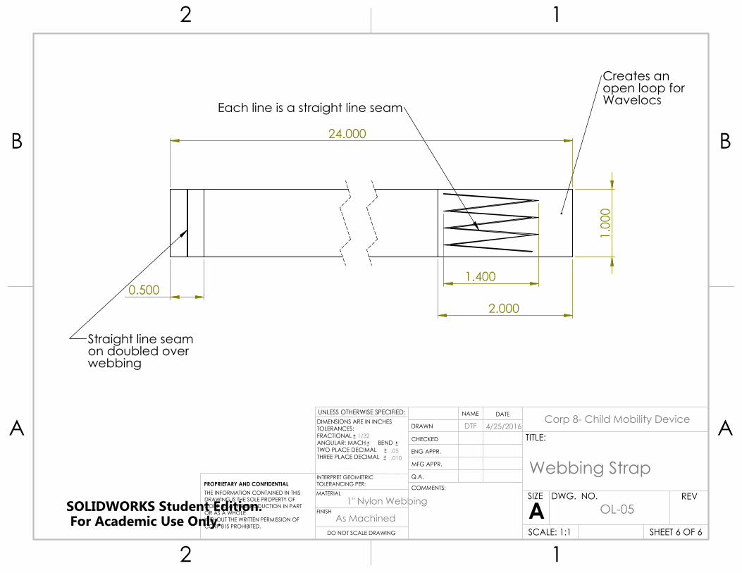
24.000
0.500 2.000
1.400
1.0
00
Straight line seam on doubled over webbing
Each line is a straight line seam
Creates an open loop for Wavelocs
UNLESS OTHERWISE SPECIFIED:
CHECKED
SIZE
TITLE:
PROPRIETARY AND CONFIDENTIALINTERPRET GEOMETRICTOLERANCING PER:
Q.A.
FINISH
DWG. NO.
DATE
A
DIMENSIONS ARE IN INCHESTOLERANCES:FRACTIONALANGULAR: MACH BEND TWO PLACE DECIMAL THREE PLACE DECIMAL
MATERIAL
NAME
REV
DO NOT SCALE DRAWING SCALE: 1:1
ENG APPR.
THE INFORMATION CONTAINED IN THISDRAWING IS THE SOLE PROPERTY OFCORP 8. ANY REPRODUCTION IN PART OR AS A WHOLEWITHOUT THE WRITTEN PERMISSION OFCORP 8 IS PROHIBITED.
COMMENTS:
DRAWN
MFG APPR.
SHEET 6 OF 6
2 1
A
B
A
B
12
Corp 8- Child Mobility Device
1" Nylon Webbing
Webbing Strap
4/25/2016DTF
OL-05As Machined
.010
.05
1/32
SOLIDWORKS Student Edition. For Academic Use Only.