n87-17731 - nasa · pdf fileminimum altitude, ft 180x 103 160 - 140 120 i00 80 15...
TRANSCRIPT
NANNED IURSMISSION
VlilIICLR DESI6NREQUIRE_KNTSPORAEROCAPTURE
Oliver Hill
Rodney O. Wallace
NASA-Johnson Space Center
Houston, Texas
ABSTRACT
The goal of this study was to define vehicle design requirements of
a reusable system for manned Mars missions which employ aerocapturtng
techniques to obtaln desired orbital velocities. Requirements for
vehicle L/D and ballistic coefficient are determined for expected aero-
capture velocities. This paper presents conclusions concerning g-loads
environment and TPS requirements for a vehicle that aerocaptures at Mars
and Earth. Although the goal of a reusable system (based on current
state-of-art technologies) was not obtained, the viability of aerocapture
at Mars and Earth was established.
INTRODUCTION
The deceleration of a vehicle from hyperbolic approach velocities to
orbital velocity at Mars and Earth can be accomplished by propulsive
braking or atmospheric braking (aerocapture). Many authors have shown
that aerocapture is more advantageous than propulsive braking in terms of
initial departure mass in Iow-Earth-orblt (LEO). Therefore, to take
advantage of aerocaptuk_ at Mars and Earth for a manned Mars mission,
vehicle design requirements must be defined in terms of external configu-
ration (L/D), size and mass (m/CDA), entry velocity, aerodynamic heating,
and g-loads. The goal of the aerocapture analysis was to define vehicle
design requirements for a reusable aerocapture system.
MARS AEROCAPTURE
Trajectory analyses of Earth to Mars transfers for arrival dates
from 1999 to 2028 have determined the entry velocity requirement to be
approximately 17,700 ft/sec to 30,000 ft/sec. This velocity range corre-
sponds to two classes of missions: conjunction class (<20,500 ft/sec)
and opposition class (>20,500 ft/sec).
In order to minimize the scope of the entry trajectory analysis, the
analysis of external configuration and mass requirements made use of
recent a_d previous Mars mission studies. Raked-off elliptical cone
N87-17731
114
https://ntrs.nasa.gov/search.jsp?R=19870008298 2018-05-23T11:37:16+00:00Z

configurations provide a range of L/D's which were assumed to be adequate
for aerocapture. Previous Mars mission studies provided estimates of
vehicle mass. With these estimates, an aerocapture analysis was con-
ducted with a modified version of the guidance logic from reference 1.
The aerocapture vehicles were assumed to be trlmmable within
+4.0 degrees of the desired angle-of-attack.
m
The aerocapture guidance was required to achieve the target apoapsls
altitude in the presence of all combinations of the following system
÷
dispersions: (I) Flight path angle dispersion of _ 0.30 degree;
@
(2) Angle of attack dispersion of _ 4.00; and (3) Mars atmosphere
density models from reference 2. A minimum altitude constraint of
100,000 feet at Mars was utilized.
An aerocapture is a guided deceleration through an entry corridor in
a planet's atmosphere to achieve a desired orbital velocity. The entry
corridor is defined by those trajectories which have flight path angles
steep enough to avoid skipping out of the atmosphere (remaining at hyper-
bolic velocity) and shallow enough to achieve a desired apoapsls while
maintaining desired g-load and aerodynamic heating levels. The vehicle
L/D is the parameter which controls the width of the entry corridor for a
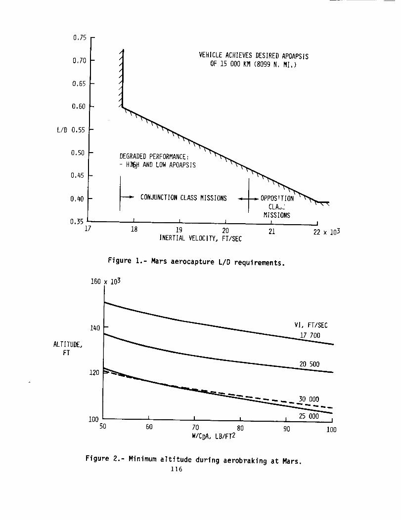
vehicle using llft vector modulation for control. Figure 1 shows the
required vehicle L/D to meet the aerocapture velocity requirements at
Mars. An L/D of 0.6 is required to satisfy the complete aerocapture
velocity range requirement. Within the aerocapture corridor the minimum
altitude of a trajectory is important for control of aerodynamic heating,
g-loads and other considerations such as obstacle avoidance. For a
specified guidance logic, the vehicle ballistic coefficient, m/CDA, is
the primary driver of the minimum altitude of an aerocapture trajectory
(Figure 2). The aerocapture analysis demonstrated that a ballistic
coefficient greater than 100 Ibm/sq ft would violate the minimum altitude
constraint at Mars (Figure 3). Therefore, the vehicle design requirement
for external configuration, size and mass is an L/D of 0.6 wlth a ballis-
tic coefficient less than 100 Ibm/sq ft. The effect of these conclusions
on the stagnation heat flux and g-load environments must also be studied
to determine thermal protection system requirements and crew environment,
Figure 4 presents the reference stagnation heating rate for a one
foot radius sphere as function of ballistic coefficient and entry
115
0,75 -
0.70 -
0,65 -
0.60 -
L/D 0,55 -
0.50 -
0,45 -
0,40 -
0.3517
VEHICLE ACHIEVES DESIRED APOAPSISi
OF 15 000 KM (8099 N. MI.)/
/
/
/
/
/
/
- H_ AND LOW APOAPSIS '
MISSIONSI I I , I I
18 19 20 21 22 x 103
INERTIAL VELOCITY,FT/SEC
Figure I.- Mars aerocapture L/D requirements.
160 x 103
ALTITUDE,
FT
140
120
i0050
_ _ 2o ooo
25 000I I , I I I
60 70 80 90 lO0W/CDA, LB/FT2
Figure 2.- Minimum altitude during aerobraking at Mars.
116

MINIMUMALTITUDE,
FT
180 x 103
160 -
140
120
i00
80
15
ENTRY CORRIDOR AT 656 168 FT
W/CDA = 100 LB/FT2
L I I
2O 25
INERTIAL VELOCITY,FT/SEC
NOMINAL
_ WORST CASE
J
30 x 103
Figure 3.- Minimum altitudes for Mars aerocapture maneuver.
STAGNATION
HEATINGRATE
(QREF),
BTU/FT2-SEC
600
5OO
400
300
2OO
100
ENTRY CORRIDOR AT 656 168 FT
QREF = 2,2 x 10⁻⁸%/-P (Vl)3
INERTIAL
VELOCITY - VI
FT/SEC _30 000
25 000
20 500
17 700
I 1 1 I I I I I I
55 60 65 70 75 80 85 90 95 100
W/CDA, LB/FT2
Figure 4.- Mars stagnation heating rates versus ballistic nund)er.
117
velocity for aerocapture at Nars. When these reference hea_lng rates are
assessed for an 85 foot diameter aerobrake, the conclusion can be drawn
that an ablative or advanced state-of-the-art TPS is required for opposi-
tion class missions and may be required for conjunction class missions.
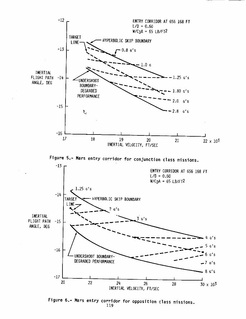
Figures 5 and 6 present the expected g-load for conjunction and
opposition class missions, respectively, within the acceptable Mars entry
corridor. The expected g-loads for conjunction class missions appear to
be acceptable, while the g-loads for opposition class missions approach
intuitively unacceptable values. However, life scientists will have to
identify acceptable g-load requirements.
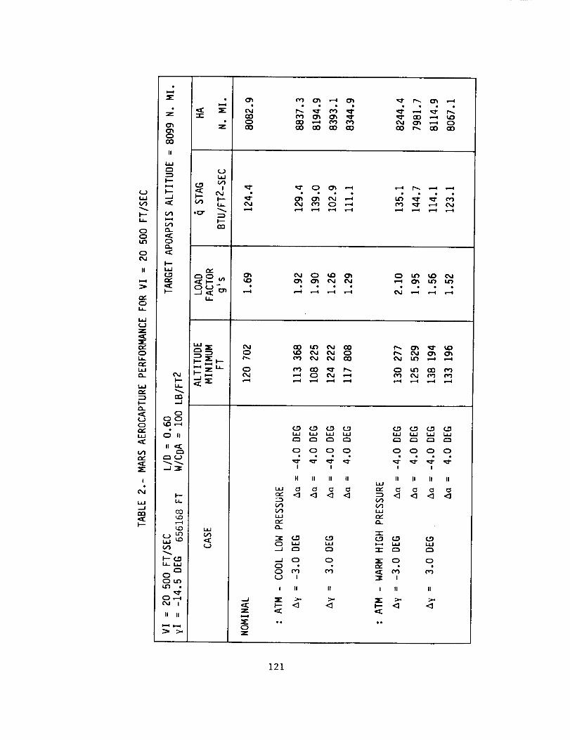
The most severe conditions for the aerocapture maneuver are produced
by analyzing a vehicle which has a ballistic coefficient of 100 lbm/sq
ft. Tables I through 4 present the detailed results of the Mars aero-
capture analysis for the complete range of approach velocities which
cover conjunction, opposition and Venus swlngby missions.
EARTH AEROCAPTURE
Trajectory analyses of Mars to Earth transfers have determined that
the maximum expected entry velocity for conjunction class missions is
38,000 ft/sec and that opposition class entry velocities significantly
exceed 38,000ft/sec. The aerocapture analysis at Earth was limited to
vehicles that satisfied the Mars aerocapture requirements because the
same vehicle was assumed to perform the Mars and Earth aerocaptures. The
analysis was also limited to conjunction class missions because the
conclusions drawn from this conjunction class analysis would only be
amplified by the more severe vehicle environment of opposition class
missions. Figures 9 and 8 present the g-load and reference stagnation
heating rates across the aerocapture corridor for a vehicle which has an
L/D of 0.6 and ballistic coefficient of approximately 55 Ibm/sq ft
(greater than expected ballistic coefficients for actual vehicle
designs). From the calculated g-load environment and extrapolations to
opposition class entry velocities, it can be concluded that the crew
would experience intuitively unacceptable g-loads. Furthermore, when
thermal protection system requirements are assessed using the data on
Figure 8 for a vehicle with an 85 foot diameter aerobrake, the conclusion
can be drawn that an ablative or advanced state-of-the-art TPS Is re-
quired. Since g-loads and a reusable TPS appear unacceptable, a
118
INERTIALFLIGHT PATHANGLE, DEG
-12
-13
-14
-15 -
-16iZ
TARGET
ENTRY CORRIDOR AT 656 168 FT
L/D : 0,60
W/CDA = 65 LB/FT2
LINE _ HYPERBOLICSKIP BOUNDARY
- _ __---_.__DEGRADED .__ --",.-- - i,80 G'S
PERFORMANCE _._"-" ---- 2,0 G'S
_--2,8 G'SL.
I 1 I 1
18 19 20 21INERTIAL VELOCITY, FT/SEC
I
22 x 103
Figure 5.- Mars entry corridor for conjunction class missions.
INERTIAL
FLIGHT PATH
ANGLE. DEG
-13
-14
-15
-16
-17
ENTRY CORRIDOR AT 656 168 FT
L/D = O,6O
W/CDA = 65 LB/FT2
8 G'S
I I I 1 I20 22 24 26 28 30 x 103
INERTIAL VELOCITY, FT/SEC
Figure 6.- Mars entry corridor for opposition class missions.119

I--
00
,....-4
II
0
,v0
0.
I--
0
!
..-I
,Z
0CO
II
._1 t--
I---
0
C._
e_._J
0O0
0 II
,,_
_j.-_
I---i,
co_o
_ c...gI-- ,.,
OoJ
",4r_ .-.4
If II
0
0
O0
W W.4 _;
O0 C_) (20 r,.,0 _ 0 0
• • e • •
_0 _ t'_ IF) Ln
I •
r_ 0 0 0e_l _ CO CO
.4 .4 c_ c_
..J
Z
0Z
0 0 0 0• • • e
J !
II II II II
ud _ 0 C_ C_
C.O (_0ud _d
C) _-_ _'_
0 C_
C)o_ _
I li 1l
0 0 0 0
I !
II II II II
¢/1
n.,"Q-
-r"0
,n,,"
I II II
120
0co
II
w
F'-- (_
(,_ I-- .:_ iI--
I-" (._ .CT .--_
C_ _-
Lr_ C_
I'--II L_ _,,
_ 0_-_-
0
--_ eni.i. -J
0ca O00 _'-_
I
d
_..i¢_ co
m _
L,_. _j
O
II II
oco
o
0
_J
z
0z
•_" CO ,---4O_ ,---40
CO t-_ GO O0
• • • e
_) od _ 0
o _0 ut_ oo ¢_oo od o_ o_
(_o (_o (_o co
0 0 0 0
I I
II II II II
ILl 0 0 C_
--_ (D (.0
•--_ 0 00o M _
I II II
I- <3 <]
0 0 0 0
i i
II II II II
Z 0 0
I II II
121

t.-...i.i...
OOo
I!
t_0
o
t_0
k-
o
I
t_
k-
o_0cO
II
I.-- o4
0
t:30 _
.:D
=,O
ooto,._
o II
I--
c0
I-- f...0
<:DOtO
o,.,4oJ !
I| II
c%J
oO0oD
_ _lD co
q_ • • Q,.-e Ll_ Ll_
_0 CO O0 CO0 0 0
r_
L_O4
0
O cO _ 00_,O t.O o'1, o0,4 _ r_ i.,")
00 o,_ _o O'_ t-,.. O ',:7
.,--I
O
o 0 0 O
I I
II II II II
,v" ":::1 "_ <1 <]
r,,"r,
O _ I._
.--I O O
! II U
O O O O
I !
II II II II
£,g _ C,O
'5" 0 0
0'13= a
I II II
I-- <] '_
122

oII
_..0i,
(Jz
0i,
i,i
w
(_)0
i,i
I
4
._1
I--
Z
u
I
_ <IE _-
.,._1
0O0
0 II
II
_j--_
L_-
O3
_Lou
I-- ,,,i, _-_
Our_Oo
II |l
0@0 CO CO
N M 0
_,D _ 0 M
CO @O _ @@
¢vICOo_
_D0
_D CO coI_ _ 0
0 0 _
.J
z
0z
w i,i _ i,i
0 0 0 o• • • e
II II II II
i.i.i
_=
0 _ r-__J
o 0
o
u I
i II II
0 0 0 0• o • •
I I
IJ II II I!
<] <] <] <]¢/1¢/)
"1-0 0
I II II
_-- <) <]
123

zo
GO
._J
I
i
z0
oz
--)z0__)
CD
i =o =_
e I N
/o_
• _
*llII
, , _-_, , _,_:I I i I I I
"-r-
--,I
_._/_J _
I---¢y -,r-
0
I
r-
or..
r,-0
0f.,.
S-O
S,.
C3.
0S.G;m
r-
S.-fl3
I
_J1-::3C3_
LL
124

Z LL
v, _ t--.-
O 0 _) 0 0 0
l.L i_'_, C,,I I,¢'_ C,_
Z
N N _/ 1
X
_ .-J
L I I _- I I i
I I O I ! I
-T- UJ
,,,,___J
_.J _
I---
_2o_
§-
000
O"I _,1B _
e-0_...
m
0Je-
e--
0
or-
4.a
vI
4-a
o1,--
3_
c_
0
oe-
s-s-oU
S.
.._4-_
£3.
_J
0!,-
O_
4_
S,.
I
125

propulsive braking system is required to augment the aerocapture system
to reduce the aerocapture velocity and, thereby, relieve g-load and aero-
heating environments of the aerocapture system.
Another approach to aerocapture at Earth is to aerocapture only part
of the Earth return vehicle. A "small" crew and Mars sample module could
be designed into the Earth return vehicle which would have a small
ballistic coefficient. The advantage of this approach is that the mini-
mum altitude during entry would be increased which would decrease the
amount of aerodynamic heating. Figures 9 and 10 present the g-load and
reference stagnation heating rates across the aerocapture corridor for a
vehicle which has an L/D of 0.6 and ballistic coefficient of 10 lbm/sq
ft. Several conclusions can be drawn from these plots. Propulsive
braking may still be required for g-load control of the small module.
However, the mass of propellent required to perform the braking of the
small module would be less than the mass of propellent required to per-
form the same functlon for the complete Earth return vehicle. Also,
reusable TPS may be acceptable only for conjunction class entry veloci-
ties for the small module.
CONCLUSION
The initial goal of the aerocapture analysis was to derive vehicle
design requirements for a reusable system that could aerocapture at Mars
and Earth. The aerocapture analyses have determined that a vehicle with
L/D of 0.6 and ballistic coefficient less than I00 Ibm/sq ft can be
aerocaptured at Mars and Earth. However, the goal of a reusable system
may be unrealistic. The TPS requirements point to non-reusable TPS or an
advanced state-of-the-art TPS. Also the expected g-load environment at
Earth points to aerocapture systems which have some propulsive braking
capability for control of the vehicle g-loads. Since TPS requirements
are affected by vehicle ballistic coefficient, reduction in ballistic
coefficient can be obtained by studying separate aerocaptures at Mars of
the Mars transfer vehicle and staged Mars landers; and at Earth by con-
sidering aerocapturing only a small crew/sample module.
RECOMMENDATIONS
The approach to this study was to make use of previous Mars mission
studies and recent raked-off cone vehicle studies. The next step will be
to take a more parametric approach to vehicle design requirements defini-
126

-3 - CONJUNCTIONCLASS MISSIONS
INERTIALFLIGHT
PATH ANGLE. DEG
-4
-5
-6
HYPERBOLIC SKIP BOUNDARYB /
TARGET _ _2 65 GLINE_ " _ _
,0 G_5,3 G
-- 6,3G
"- UNDERSHOOT BOUNDARY
-9 I I
32 000 38 000 40 000
ENTRY CORRIDORAT 400 000 FT
L/D : 0,60
W/CDA : 10,0 LB/FT2
I I
34 000 36 000
INERTIALVELOCITY.FT/SEC
Figure 9.- Earth aerocapture corridor with g-loads.
INERTIALFLIGHT
PATH ANGLE. DEG
-3
-4
-5
-6
-7
-8
CONJUNCTIONCLASS MISSIONS REFERENCE STAGNATION
HEATING RATE - _REF
86/_i . .BTU/FT2-SEC
TARGET j_..._ _139LINE_ -_
----""-'__154
__180
221..... _ \ \_248
-9 I I32 000 38 000 40 000
ENTRY CORRIDOR AT 400 000 FT
L/D = 0,60
W/CDA = 10,0 LB/FT2
QREF = 1,77 x I0-8_(VI)3,07
I I
34 000 36 000
INERTIALVELOCITY.FT/SEC
Figure I0.- Earth aerocapture corridor with stagnation heating rates.
127

tion by assessing a larger range of L/D, ballistic coefficient, and
external configuration. Preliminary analyses i_dlcate that an advance-
ment in the state-of-the-art TPS technology is required to make a
reusable system possible. Therefore, further TPS studies are
recommended. Finally, the allowable crew entry g-load levels require
definition for the case of long exposure to zero g or low level g.
Physiological tests could be performed during an Apollo type entry from
Space Station for a crew made up of personnel who have had long exposure
to zero g and personnel who have not.
REFERENCES
1. AAS paper 83-357, "An Adaptive Guidance Logic for an
Aeroasslsted Orbital Transfer Vehicle", August 22-
25,1983, by Oliver Hill, NASA Johnson Space Center,
Houston, Texas
2. "The Nars Reference Atmosphere", Advanced Space
Research Vol 2, pp 3-17, 1982 COSPAR, edited by A.
Kllore.
Oem tAL
OF POOS Aurv
128