name of work: construction of marketing development cum ...€¦ · name of work: construction of...
TRANSCRIPT
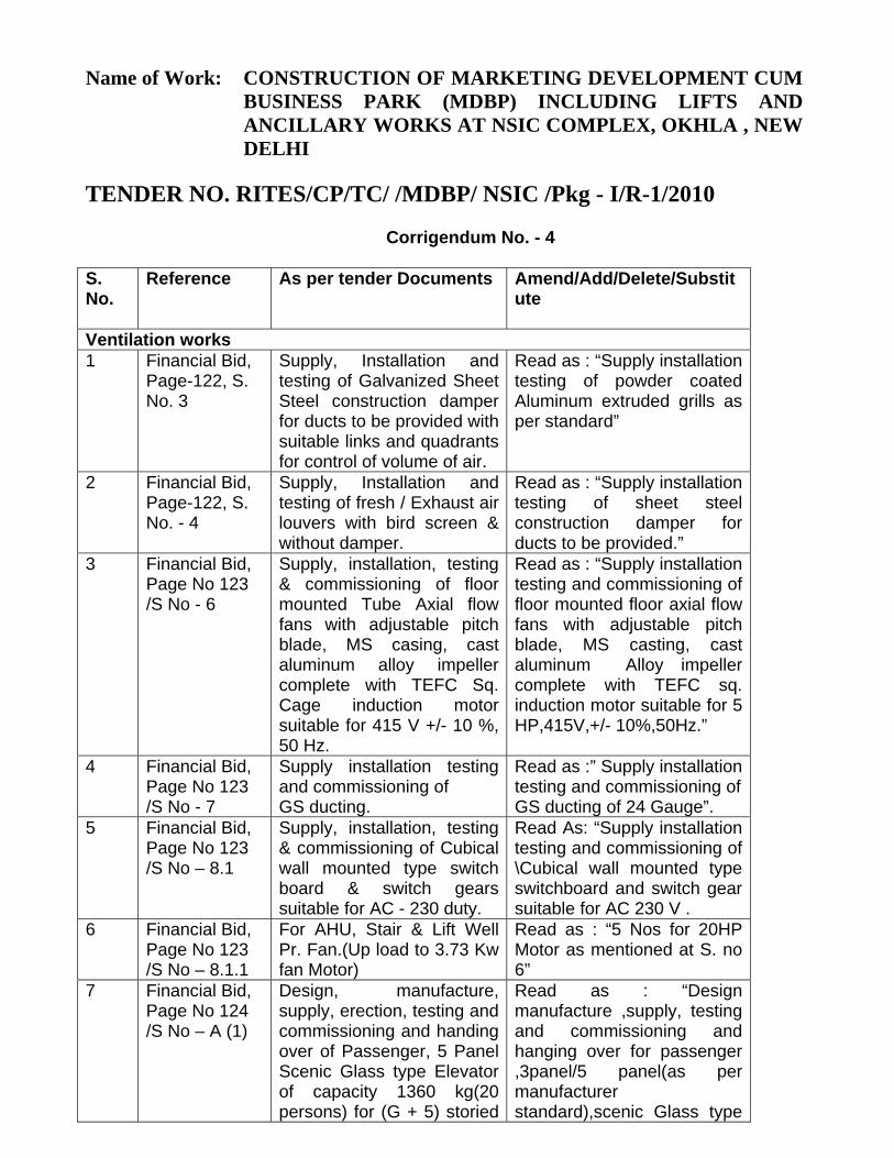
Name of Work: CONSTRUCTION OF MARKETING DEVELOPMENT CUM BUSINESS PARK (MDBP) INCLUDING LIFTS AND ANCILLARY WORKS AT NSIC COMPLEX, OKHLA , NEW DELHI
TENDER NO. RITES/CP/TC/ /MDBP/ NSIC /Pkg - I/R-1/2010
Corrigendum No. - 4 S. No.
Reference As per tender Documents Amend/Add/Delete/Substitute
Ventilation works 1 Financial Bid,
Page-122, S. No. 3
Supply, Installation and testing of Galvanized Sheet Steel construction damper for ducts to be provided with suitable links and quadrants for control of volume of air.
Read as : “Supply installation testing of powder coated Aluminum extruded grills as per standard”
2 Financial Bid, Page-122, S. No. - 4
Supply, Installation and testing of fresh / Exhaust air louvers with bird screen & without damper.
Read as : “Supply installation testing of sheet steel construction damper for ducts to be provided.”
3 Financial Bid, Page No 123 /S No - 6
Supply, installation, testing & commissioning of floor mounted Tube Axial flow fans with adjustable pitch blade, MS casing, cast aluminum alloy impeller complete with TEFC Sq. Cage induction motor suitable for 415 V +/- 10 %, 50 Hz.
Read as : “Supply installation testing and commissioning of floor mounted floor axial flow fans with adjustable pitch blade, MS casting, cast aluminum Alloy impeller complete with TEFC sq. induction motor suitable for 5 HP,415V,+/- 10%,50Hz.”
4 Financial Bid, Page No 123 /S No - 7
Supply installation testing and commissioning of GS ducting.
Read as :” Supply installation testing and commissioning of GS ducting of 24 Gauge”.
5 Financial Bid, Page No 123 /S No – 8.1
Supply, installation, testing & commissioning of Cubical wall mounted type switch board & switch gears suitable for AC - 230 duty.
Read As: “Supply installation testing and commissioning of \Cubical wall mounted type switchboard and switch gear suitable for AC 230 V .
6 Financial Bid, Page No 123 /S No – 8.1.1
For AHU, Stair & Lift Well Pr. Fan.(Up load to 3.73 Kw fan Motor)
Read as : “5 Nos for 20HP Motor as mentioned at S. no 6”
7 Financial Bid, Page No 124 /S No – A (1)
Design, manufacture, supply, erection, testing and commissioning and handing over of Passenger, 5 Panel Scenic Glass type Elevator of capacity 1360 kg(20 persons) for (G + 5) storied
Read as : “Design manufacture ,supply, testing and commissioning and hanging over for passenger ,3panel/5 panel(as per manufacturer standard),scenic Glass type

S. No.
Reference As per tender Documents Amend/Add/Delete/Substitute
Building with the following specifications”:
elevator of capacity 1360 kg (20 persons) for (G+5) storied building with the following specifications:”
8 Financial Bid, Page No 125 /S No – A (1)
“Design, manufacture, supply, erection, testing and commissioning and handing over of Passenger, 5 Panel Scenic Glass type Elevator suitable for handicapped persons of capacity 1360 kg(20 persons) for (G + 5) storied Building with the following specifications:”
Read as : “Design manufacture ,supply, testing and commissioning and hanging over for passenger ,3panel/5 panel(as per manufacturer standard),scenic Glass type elevator suitable for handicapped persons of capacity 1360 kg (20 persons) for (G+5) storied building with the following specifications:”
9 Financial Bid, Page No 93 S. No. – NS2
“Providing and fixing in position 0.90 mm high……”
Amend as “Providing and fixing in position 0.90 m high……”
10 Financial Bid, Page No 93 S. No. – NS2
“Steel fabricators ao equivalent approved with three ……”
Amend as “Steel fabricators or equivalent approved with three ……”
11 Financial Bid, Page No 21, S. No. – 46, DSR Item No. 9.1.1
Second Class Sal wood Amend as “Second Class Teak wood”
12 Financial Bid, Page No 29, S. No. – 64, DSR Item No. 8.2.2.2, column No. 6(Rate)
In place of “2543.65” Substitute with “2575.10”
13 Financial Bid, Page No 29, S. No. – 64, DSR Item No. 8.2.2.2, column No. 7(Amount)
In place of “22094143.90” Substitute with “22367318.60”
14 Financial Bid, Page No 31, S. No. – 68, DSR Item No. 11.4, column No. 2
In place of “11.4” Substitute with “11.40”
15 Financial Bid, In place of “13.1” Substitute with “13.10”

S. No.
Reference As per tender Documents Amend/Add/Delete/Substitute
Page No 36, S. No. – 82(b), DSR Item No. 13.1, column No. 2
16 Financial Bid, Page No 36, S. No. – 82(b), DSR Item No. 13.1, column No. 3(Description of Items)
In place of “1:4” Substitute with “1:3”
17 Financial Bid, Page No 36, S. No. – 82(b), DSR Item No. 13.1, column No. 6(Rate)
In place of “90.35” Substitute with “128.50”
18 Financial Bid, Page No 36, S. No. – 82(b), DSR Item No. 13.1, column No. 7(Amount)
In place of “81065.63” Substitute with “115295.34”
19 Financial Bid, Page No 64, S. No. – 9, DSR Item No. 16.30.2, column No. 6(Rate)
In place of “17.20” Substitute with “17.15”
20 Financial Bid, Page No 64, S. No. – 10, DSR Item No. 16.56.1, column No. 6(Rate)
In place of “5856.10” Substitute with “5856.05”
21 Financial Bid, Page No 73, S. No. – 1, DSR Item No. 16.43, column No. 2
In place of “16.43” Substitute with “16.75”
22 Financial Bid, Page No 81, S. No. – 2, DSR Item No.
In place of “123.50” Substitute with “78.55”
S. No.
Reference As per tender Documents Amend/Add/Delete/Substitute
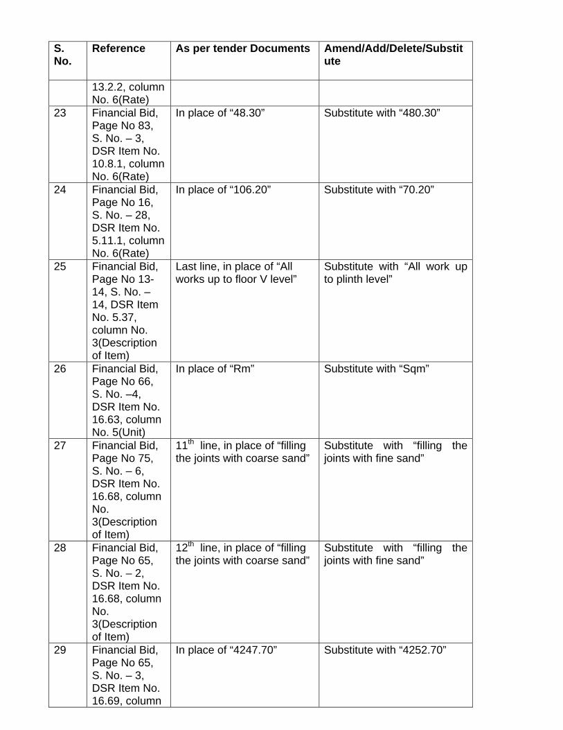
13.2.2, column No. 6(Rate)
23 Financial Bid, Page No 83, S. No. – 3, DSR Item No. 10.8.1, column No. 6(Rate)
In place of “48.30” Substitute with “480.30”
24 Financial Bid, Page No 16, S. No. – 28, DSR Item No. 5.11.1, column No. 6(Rate)
In place of “106.20” Substitute with “70.20”
25 Financial Bid, Page No 13-14, S. No. – 14, DSR Item No. 5.37, column No. 3(Description of Item)
Last line, in place of “All works up to floor V level”
Substitute with “All work up to plinth level”
26 Financial Bid, Page No 66, S. No. –4, DSR Item No. 16.63, column No. 5(Unit)
In place of “Rm” Substitute with “Sqm”
27 Financial Bid, Page No 75, S. No. – 6, DSR Item No. 16.68, column No. 3(Description of Item)
11th line, in place of “filling the joints with coarse sand”
Substitute with “filling the joints with fine sand”
28 Financial Bid, Page No 65, S. No. – 2, DSR Item No. 16.68, column No. 3(Description of Item)
12th line, in place of “filling the joints with coarse sand”
Substitute with “filling the joints with fine sand”
29 Financial Bid, Page No 65, S. No. – 3, DSR Item No. 16.69, column
In place of “4247.70” Substitute with “4252.70”

S. No.
Reference As per tender Documents Amend/Add/Delete/Substitute
No. 6(Rate) 30 Financial Bid,
Page No 47, S. No. – 2, DSR Item No. 18.11, column No. 3(Description of Item)
1st line Add “Providing and fixing G.I. pipes complete with GI fittings and clamps including making good the walls etc.” before “concealed pipe….”
31 Financial Bid, Page No 47, S. No. – 2, DSR Item No. 18.11.2, column No. 6(Rate)
In place of “170.15” Substitute with “170.60”
32 Financial Bid, Page No 47, S. No. – 4, DSR Item No. 18.38.1, column No. 6(Rate)
In place of “4.65” Substitute with “4.80”
33 Financial Bid, Page No 47, S. No. – 4, DSR Item No. 18.38.2, column No. 6(Rate)
In place of “5.45” Substitute with “5.65”
34 Financial Bid, Page No 47, S. No. – 4, DSR Item No. 18.38.3, column No. 6(Rate)
In place of “7.20” Substitute with “7.45”
35 Financial Bid, Page No 47, S. No. – 4, DSR Item No. 18.38.4, column No. 6(Rate)
In place of “8.50” Substitute with “8.75”
36 Financial Bid, Page No 47, S. No. – 4, DSR Item No. 18.38.5,
In place of “10.10” Substitute with “10.40”

S. No.
Reference As per tender Documents Amend/Add/Delete/Substitute
column No. 6(Rate)
37 Financial Bid, Page No 47, S. No. – 4, DSR Item No. 18.38.6, column No. 6(Rate)
In place of “11.80” Substitute with “12.20”
38 Financial Bid, Page No 71, S. No. – 1, DSR Item No. 19.1, column No. 3(Description of Item)
2nd line, in place of “grade ‘A’ ”
Substitute with “class SP-1”
39 Financial Bid, Page No 77, S. No. – 1, DSR Item No. 19.1, column No. 3(Description of Item)
2nd line, in place of “grade ‘A’ ”
Substitute with “class SP-1”
40 Financial Bid, Page No 72, S. No. – 3, DSR Item No. 19.4, column No. 3(Description of Item)
2nd line, in place of “grade ‘A’ ”
Substitute with “class SP-1”
41 Financial Bid, Page No 78, S. No. – 3, DSR Item No. 19.4, column No. 3(Description of Item)
2nd line, in place of “grade ‘A’ ”
Substitute with “class SP-1”
42 Financial Bid, Page No 71, S. No. – 6, DSR Item No. 19.10.1, column No. 6(Rate)
In place of “2289.75” Substitute with “2289.80”
43 Financial Bid, 1st line, in place of “required Substitute with “required
S. No.
Reference As per tender Documents Amend/Add/Delete/Substitute
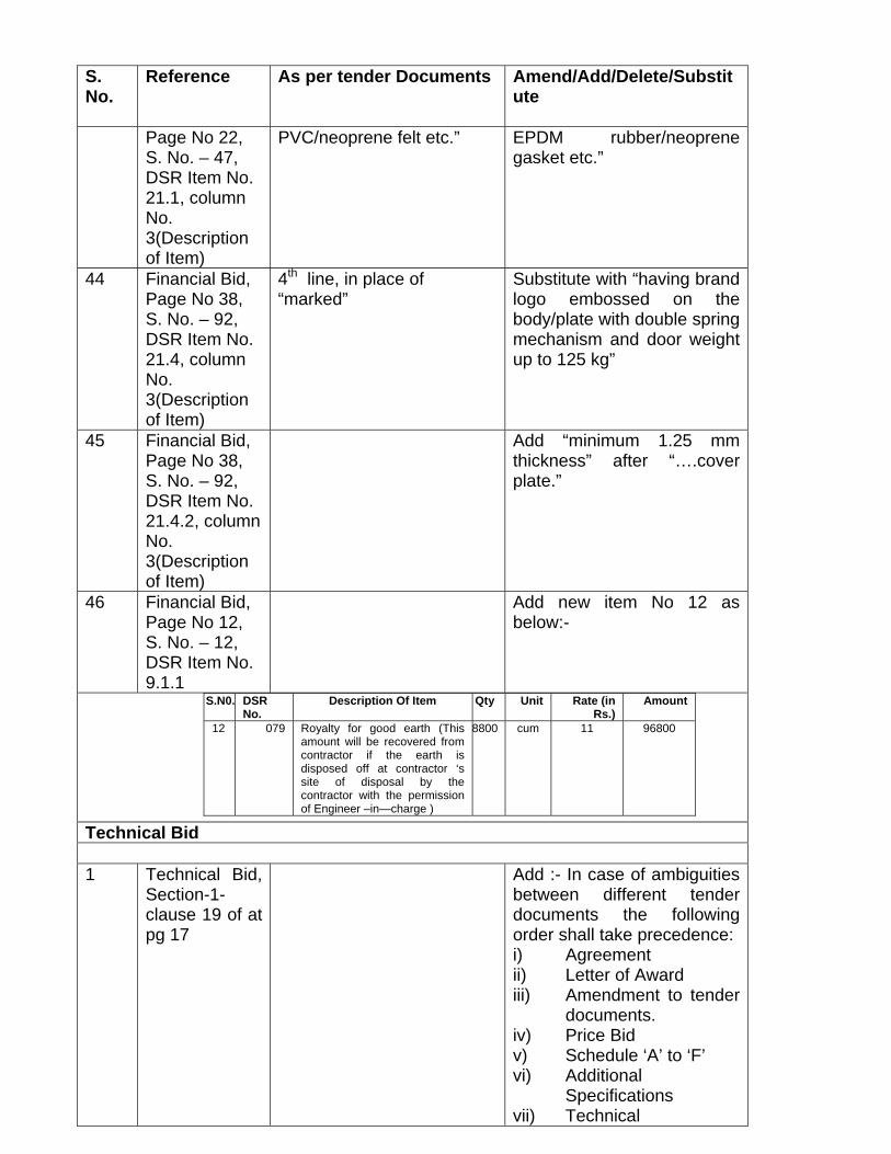
Page No 22, S. No. – 47, DSR Item No. 21.1, column No. 3(Description of Item)
PVC/neoprene felt etc.” EPDM rubber/neoprene gasket etc.”
44 Financial Bid, Page No 38, S. No. – 92, DSR Item No. 21.4, column No. 3(Description of Item)
4th line, in place of “marked”
Substitute with “having brand logo embossed on the body/plate with double spring mechanism and door weight up to 125 kg”
45 Financial Bid, Page No 38, S. No. – 92, DSR Item No. 21.4.2, column No. 3(Description of Item)
Add “minimum 1.25 mm thickness” after “….cover plate.”
46 Financial Bid, Page No 12, S. No. – 12, DSR Item No. 9.1.1
Add new item No 12 as below:-
S.N0. DSR No.
Description Of Item Qty Unit Rate (in Rs.)
Amount
12 079 Royalty for good earth (This amount will be recovered from contractor if the earth is disposed off at contractor ‘s site of disposal by the contractor with the permission of Engineer –in—charge )
8800 cum 11 96800
Technical Bid 1 Technical Bid,
Section-1- clause 19 of at pg 17
Add :- In case of ambiguities between different tender documents the following order shall take precedence: i) Agreement ii) Letter of Award iii) Amendment to tender
documents. iv) Price Bid v) Schedule ‘A’ to ‘F’ vi) Additional
Specifications vii) Technical

S. No.
Reference As per tender Documents Amend/Add/Delete/Substitute
Specifications viii) Drawings ix) Notice Inviting Tender
and Instruction to Tenderers
x) Special Conditions Of Contract
xi) General Conditions of Contract
xii) Conditions of Contract
2 Technical Bid, Section-1-1st sentence of clause 1.1 of section- 1 at pg 3
Tenders are invited by RITES….acting for and on behalf of NSIC as an agent and power of attorney from contractors…
Amend as Tenders are invited by RITES….acting for and on behalf of NSIC as an executing agency, from contractors…
3 Technical Bid, Section-1-2nd sentence of clause 11.7 (i) of pg-12
“The integrity pact has already been signed by RITES for and on behalf of owner as his agent”
“delete the words -for and on behalf of owner as his agent”
4 Technical Bid, Clause 10D of section -IV at Page 76
“Dismantled material Employer’s property”
Amend as “Dismantled Material Owner’s Property”
5 Technical Bid, 2nd para of clause 17 of section -4 at page 84
The specialized items of work such as Anti termite treatment, water proofing work, kiln seasoned and chemically treated wooden shutters etc. shall be entrusted to specialized firm or Registered Contractor who shall give specific guarantees that they shall be responsible for removal of any defect cropping up in these works executed by them within the Guarantee period. The form in which the Guarantee is to be executed by the Contractor on a stamp paper of the required value is at Annexure E1 & E2 respectively for Water Proofing Works and Anti Termite Treatment Works.
Amend as : - The specialized items of work such as Anti termite treatment, water proofing work, kiln seasoned and chemically treated wooden shutters etc. shall be entrusted to specialized firm or Registered Contractor who shall give specific guarantees that they shall be responsible for removal of any defect cropping up in these works executed by them within the Guarantee period. The Guarantee for water proofing work shall be furnished in the form of Bank Guarantee as per stipulation under clause No.8.0 of Special conditions of Contract. The Guarantee for Anti Termite Treatment Works to be furnished on a
S. No.
Reference As per tender Documents Amend/Add/Delete/Substitute
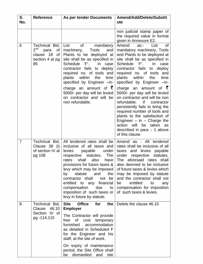
non judicial stamp paper of the required value in format given in Annexure E2.
6 Technical Bid, 2nd para of clause 18 of section 4 at pg 85
List of mandatory machinery, Tools and Plants to be deployed at site shall be as specified in Schedule ‘F’. In case contractor fails to deploy required no. of tools and plants within the time specified by Engineer –in-charge an amount of ` 5000/- per day will be levied on contractor and will be non refundable.
Amend as:- List of mandatory machinery, Tools and Plants to be deployed at site shall be as specified in Schedule ‘F’. In case contractor fails to deploy required no. of tools and plants within the time specified by Engineer –in-charge an amount of ` 5000/- per day will be levied on contractor and will be non refundable. if contractor persistently fails to bring the required number of tools and plants to the satisfaction of Engineer – in – Charge the action will be taken as described in para – 1 above of this clause.
7 Technical Bid, Clause 38 (i) of section IV at pg 108
All tendered rates shall be inclusive of all taxes and levies payable under respective statutes. The rates shall also have provisions for future taxes & levy which may be imposed by statute and the contractor shall not be entitled to any financial compensation due to imposition of such taxes or levy in future by statute.
Amend as : All tendered rates shall be inclusive of all taxes and levies payable under respective statutes. The aforesaid rates shall also deemed to be inclusive of future taxes & levies which may be imposed by statute and the contractor shall not be entitled to any compensation for imposition of such taxes & levies.
8 Technical Bid, Clause 46.10 Section IV of pg -114,115
Site Office for the Employer
The Contractor will provide free of cost temporary furnished accommodation as detailed in Scheduled F for the Engineer and his staff, at the site of work.
On expiry of maintenance period, the Site Office shall be dismantled and site
Delete the clause 46.10

S. No.
Reference As per tender Documents Amend/Add/Delete/Substitute
cleared unless the Employer directs otherwise. The furniture will be returned to the Contractor at whatever condition they are on expiry of maintenance period. (i.e. Defect Liability period).
9 Technical Bid, Clause 46.11.1A of section IV at Page 115
46.11 Electricity Supply required at the works
46.11.1 Arrangement
Amend as :- 46.11 Electricity Supply required at the works
46.11.1 Arrangement - Deleted
10 Technical Bid, Clause-55 section IV at Pg 131
Add Clause 55 as:- “The contractor shall construct one sample toilet and a mock-up of lobby area (Size 4mx4m in plan) at first floor of the building and get the same approved from Employer including approval of fittings, fixtures, finishing items and colour scheme. Employer shall give approval of sample within fifteen days of its completion in all respects including rectification of defects, if any. a) All fitments and fixtures used, such as electrical fittings, woodwork and joinery will be as per contract agreement.
b) The sample as stated above shall act as a guideline for the construction and finishes of all the floors. c) The sample as stated above shall be completed in all respects including all fittings and fixtures within a period as specified in schedule ‘F’ from the date of start, failing which a penalty of Rs. 2000/-(Rupees two thousand only) per day shall be levied. Provided always that

S. No.
Reference As per tender Documents Amend/Add/Delete/Substitute
provision of clause 55 shall be applicable only when provided in schedule-‘F’.”
11 Technical Bid, Annexure A to Section IV at page 132 & 133
Annexure A Substitute the Annexure A as given as enclosure -1
12 Technical Bid, Annexure C to the section IV at Page 139 to 141
Annexure C Substitute the Annexure C as given as enclosure -2
13 Technical Bid, Clause 17 of section 8 at page 176
In the last line “relating top other contracts being executed by him under the control of the employer”
Amend as:- “relating to other contracts being executed by him under the control of the employer”.
14 Technical Bid, Clause 1.1.1 of section IX at pg 178
All the works under this contract shall be executed in accordance with the designs ,CPWD specifications,(1996 Vol I to VI) with the updated correction slips issued up to the due date of recept of tenders and additional /particular specifications.
Amend as:- All the works under this contract shall be executed in accordance with the designs, Latest Specifications of CPWD with up to date correction slips as on date of submission of tender. For NON CPWD items, Technical Specifications under Section 9 & Additional Specifications under Section 10 shall be applicable.
15 Technical Bid, Schedule F at Pg 268
Performance guarantee and additional performance guarantee(Refer Clause 1) 5% of tendered value
Amend as :- ‘Performance guarantee(refer Clause 1) 5% of tendered value and additional performance guarantee as decided by Engineer-In-Charge.
16 Technical Bid, Clause 7 Schedule F At page 270
The gross work to be done together with net payment /adjustment of advances for material collected if any since the last such payment for being eligible to interim payment.
1. 3 months from start -1 crore
2. 3-15 months-1.5 crore
Amend as :- The gross work to be done together with net payment /adjustment of advances for material collected if any since the last such payment for being eligible to interim payment.
1. 3 months from start -1 crore
2. 3-12 months-1.5 crore 3. 12-15 month – 1 crore

S. No.
Reference As per tender Documents Amend/Add/Delete/Substitute
3. 15-18 month – 1 crore
17 Technical Bid, Clause 11 of schedule F at pg 270 to 271
Specification to be followed for execution of work. For CPWD DSR items… CPWD specification 1996 VOl I to VI and revised specifications 2002 for cement mortar ,Cement concrete and RCC works. CPWD general specifications for electrical works (internal -2005,external 1994)lifts and escalators-2003 ,HVAC 2004 ,Substations 2007,DG Sets 2006 all with up to date correction read with specifications with section IX of tender document FOR NON CPWD ITEMS Special specifications under Section IX
Amend as :- Specifications to be followed for execution of work For CPWD DSR items: Latest CPWD specifications with up to date correction slips as on date of submission of tender. For NON CPWD items: Technical Specifications under Section 9 & Additional Specifications under Section 10.
18 Clause 46.10 of schedule F at Page 273
Clause 46.10 Amend as: Clause 46.10-Deleted
19 Clause 55 of schedule F at Pg 273
Add clause 55 as under:- “Clause 55 – Whether clause 55 shall be applicable – yes If Yes, time allowed for completion of sample – Nine Months.”
20 Technical Bid, Section-10-Additional Specifications, Page -265
CCTV & Public Address System- Specification & Approved make - not given
Add after page 265 -“Technical Specification for CCTV and PA System” (Enclosure - 3).
21 Technical Bid, Section-10-Additional Specifications, Page -196- Item No. NS-(2)
“Providing and fixing in position 0.90 mm high……”
Amend as “Providing and fixing in position 0.90 m high……”
22 Technical Bid, Section-4-Clauses of
Sales Tax/VAT (except service Tax) or any other tax on material, sales tax on
Amend as: Sales Tax/VAT or any other tax on material, sales tax on works (if any)

S. No.
Reference As per tender Documents Amend/Add/Delete/Substitute
contract, Page -108- clause 37 (i)
works (if any) and tax of any type on labour service tax and cess under “The Building and Other Construction Workers Welfare Cess act 1996 and cess rules 1998 in respect of this contract shall be payable by the contractor and the employer, shall not entertain any claim whatsoever in this respect.
and tax of any type on labour service tax and cess under “The Building and Other Construction Workers Welfare Cess act 1996 and cess rules 1998 in respect of this contract shall be payable by the contractor and the employer, shall not entertain any claim whatsoever in this respect.
23 Technical Bid, Section-4-Clauses of contract, Page -108- clause 37 (iv)
Tax deduction at Source will be done by the employer towards Income ,sales tax on works ,Labour welfare Cess and any other tax (except service tax )as required by law ,from running Account and final bills .
Tax deduction at Source will be done by the employer towards Income, sales tax on works, Labour Welfare Cess and any other tax as required by law ,from Running Account and Final Bills .
24 Technical Bid, Section-12-Drawings, Page -39
Drawings Add drawings after page 39: Drg. No. ARCH/T/14 – Door Details Drg. No. ARCH/T/15 – Window Details Drg. No. ARCH/T/16 - Structural Glazing Details (Enclosed)
25 Technical Bid, Section-9-Technical Specifications, List of Approved Manufacturers/ make of Material (For Civil Works) Page -184- S. No. 26
GE(LEXON),DANPAL,VMI Plastics, Everest Industries Ltd.
Amend as “GE(LEXON),DANPAL,VMI Plastics, Everest Industries Ltd., Gallina
26 Pre Bid Minutes
Enclosed as Enclosure-4

Enclosure-1
ANNXURE A
FORMAT OF PERFORMANCE BANK GUARANTEE
Note: This Guarantee should be executed on Non-judicial paper of appropriate value.
Ref. No.------------------------------
THIS GUARANTEE made on this -------------------------------day of ---------------------------------- (month) 20 (Year) on --------------------------------------Bank (address) (here in after called the Bank) which expression shall unless repugnant to the context or contrary to the meaning thereof include its successors on one part and RITES Ltd, having its Corporate Office at RITES BHAWAN, Plot No.1, Sector 29, Gurgaon (Haryana), hereinafter called the Employer (which expression shall include the successors and assignees), on the other part.
WHEREAS the Employer has placed a Contract with---------------------------(hereinafter called the Contractor) having its Registered office at ---------------------------- for--------------------(hereinafter called the work) at the total cost of Rs.-----------------------------(Rupees ----------------------------------------------- only).
WHEREAS it is one of the terms of the said contract that the contractor shall furnish to the employer a Guarantee of a Bank which shall be for an amount of Rs.---------------------------------------------------------------------and shall be valid for the entire work covered by the said contract and the entire period of defect liability in respect of the said work.
WHEREAS the bank has, at the request of the contractor, agreed to give in favour of the employer a guarantee in the manner hereinafter appearing, which the employer has agreed to accept.
THIS DEED WITNESSETH as follows:
1.0 In pursuance of the said agreement and in consideration of the promises, the bank hereby Guarantee to the Employer due observance and fulfillment by the Contractor of the terms for the said Contract relating to the said work and of the performance warranty which is a part of the said contract and agrees and undertakes that if the contractor fails to observe and fulfill the said terms of the said contract and/or the performance warranty, then the bank shall immediately pay to the Employer on demand such sum or, sums of money to the extent of Rs.__________________________ (Rupees _________________________________ only) being ______________% of the value of the said contract on account of losses and

Sheet-II
damages suffered by the employer as may be claimed by the employer by reason of such non observance and non fulfillment by the contractor as aforesaid and shall also indemnify the Employer against all costs, in connection herewith against all costs, charges, expenses which may be incurred by the employer in connection here in with.
2.0 This guarantee is a continuing guarantee and not revocable except with the previous written consent of the employer and save as aforesaid it will continue to be in force until the contractor has maintained the schedule of delivery of the said work under the said contract and observed and fulfilled the said performance warrantee and all other terms and conditions of the said contract. The guarantee is valid up to ______________.
3.0 The employer may , without affecting bank’s liabilities and obligations here under, grant time or other indulgence to or compound with the contractor or enter in to any agreement of agreed for bear to enforce any other terms and conditions of the said contract against the contractor or agree to vary any of the terms and conditions of the said contract.
4.0 This guarantee shall not be affected by any change in the constitutions of the Employer by absorption with any other body or corporation or otherwise and this guarantee will be available / or enforceable by such body or corporation.
5.0 All compositions and payments received by the Employer on behalf of the contractor shall be regarded as payments in gross and in the event of the contract being wound up ,The Employer will be entitled to prove against the properties of the contractor in respect of the whole of the contractors indebtedness to the employer, without any right of the part of the bank to stand in the employers place in respect of or to claim the benefits of such composition and payment or any security held by the employer shall have received the full amount of the claims against the contractor.
6.0 In order to give effect of this guarantee the employer will be entitled to act as if the bank were the principal debtor and the bank hereby waives all and any of its rights of surety ship.
7.0 This guarantee shall continue to be in force notwithstanding the discharge of the contractor by operation of law and shall cease only the payment of the full amount by the bank to the employer of the amount hereby secured and on the claim of the employer against the contractor in respect of the said Contract being satisfied. However the guarantee is valid upto ____________________________.

Sheet-III
8.0 This guarantee shall be in addition to and not in substitution for any other guarantee or security for the contractor given or to be given to the employer in respect of the said Contract by the bank(whether alone or jointly with others).
9.0 Unless demand or claim under the guarantee is made within six months from the date of expiry of this guarantee, all the rights of the employer hereunder shall be forfeited and the Bank shall be relieved and discharged of all liabilities hereunder.
10.0 These present shall be governed by and construed in accordance with Indian law.
11.0 Subject to clause 2 hereof this guarantee remain enforce for completion period of the work under the said contract i.e upto ______________________
12.0 Any notice by way of request, demand or otherwise hereunder may be sent by post to the bank addressed as aforesaid and if sent by post it shall be deemed to have been given at the time when it would be delivered in due course of post and in proving such notice, when given by post, it shall be sufficient to prove that the envelope containing the notice was posted and a certificate signed by an officer of the employer that the envelope was so posted shall be conclusive.
13.0 Notwithstanding anything contained hereinbefore, our liability under this guarantee is restricted to Rs._____________________(Rupees________________________________________________________________________________________ only) and it will remain in force __________________________. Unless a claim or demand in writing is made with us under this guarantee on or before ___________________________, all the rights of the employer under the said guarantee shall be forfeited and we shall be relieved of liabilities there under.
14.0 The bank declares that it has the power to issue the guarantee under Regulations 1959 and the undersigned has full power to do so on behalf of the Bank.
CORPORATE SEAL Seal
Signature of issuing authority with seal
FOR __________________________________ (BANK)

Enclosure-2 ANNEXURE ‘C’
FORMAT FOR BANK GUARANTEE FOR ADVANCE PAYMENT TO CONTRACTORS
(Note:- This Guarantee should be executed on Non-Judicial Stamp Paper of Appropriate Value)
Ref. No.____________________
Whereas RITES Ltd. (hereinafter referred to as the "Employer") (which expression shall unless repugnant to the context include its legal representatives, successors and assigns, have a agreement (hereinafter referred to as the “Agreement”) with M/s ______________________________ (hereinafter referred to as the “Contractor") which expression shall unless repugnant to the context, include its legal representatives, successors and assigns for the design/supply of equipment for its plants.
AND WHEREAS one of the conditions of the agreement entered with the Contractor is that the employer should make and advance payment of Rs.______________________ (Rupees only) being _______________ % of the work Order Price against an indemnity in the form of a Bank Guarantee from a scheduled Bank in a form acceptable to employer. AND WHEREAS, at the request of the Contractor, Employer has agreed to accept a Bank Guarantee from _____________ with Registered Office at _________________ and having a Branch Office at _______________________________ (hereinafter called the ‘Bank’). NOW THIS GUARANTEE WITNESSETH that in consideration of the Employer having at the request of the contractor agreed to accept a Bank guarantee of the Bank in respect of Rs._______________________ (Rupees ________________ only) required by Contractor from the Employer for the works stipulated in the Contract Agreement, which figure of advance shall become reduced and extinguished as hereinafter set forth the Bank hereby indemnified payment without protest or demur and without recourse to the Contractor, to the said Employer up to and not exceeding altogether a sum of Rs._______________ (Rupees_______________________________________ only) being the amount of the 100% (hundred percent) of the advance payment or such other unadjusted amount of the said advance. The decision of the Employer as to whether the terms and conditions of this Guarantee have been observed shall be final and binding of the Bank. THE GUARANTEE HEREIN CONTAINED is not revocable by notice during the currency and will remain in full force until (a) payment has been made to the Employer by the bank of the aggregated amount payable here in under or (b) the said advance has been fully adjusted and extinguished, as hereafter set forth, whichever is earlier. Out of the gross amount due will be deducted by way of adjustment of the said ________________ (Rupees)_______________________________________ only).
Sheet-II
UNLESS PREVIOUSLY CANCELLED BY THE EMPLOYER, this Indemnity will remain in force up to _____________ months from the date of issue of the Guarantee i.e. upto _________________ and will stand automatically cancelled on the expiry of the said period longer than contemplated hereunder. Unless demand or claim under this Guarantee is, made on us in writing within six months from the date of the expiry of this Guarantee all the rights of the Employer against us hereunder shall be forfeited and we shall be relieved and discharged from all liabilities hereunder. The Bank declares that it has the power to issue the Guarantee under Regulations 1959 and the undersigned has full powers to do so on behalf of the bank. Signature of issuing authority with seal DATED This ________ _________ day

Enclosure-3 Specifications for CCTV System
Indoor 3.6 mm fixed-focal Dome Closed Circuit Video Surveillance Systems. 1. High Resolution Fixed Dome Camera with Wide Dynamic Range: [Model No - HDC-890 P36 I P60 I PV] 1.1The fixed dome camera should have the following features: 1/3" CCD with superior digital signal processing icore ™ Enhanced back light compensation which shall also able to mask strong light focusing directly onto the cameras. Masking colors should be selectable from White / Gray / Black. Other Enhanced features such as Wide Dynamic Range, Digital Noise Reduction, PIP (picture in picture), Quad View, Mirror, Digital Zoom, Motion detection and Privacy masking 3-Axis rotation Design and 360°+ I 0° horizontal rotation Multi-language OSD The camera should meet the minimum following specifications:
Video Format
PAL
Horizontal Resolution (TVL) Minimum 580 TVL
Type of CCD
1/3" Interline CCD
Effective Pixels
752 (H) x 582 (V)
Minimum Illumination
1.0 lx (Day mode); 0.01 lx(DSS)
Synchronization
Internal
Electronic Shutter
1/50 - 11100,000 sec
S/N Ratio 50 dB or more
AGC
Yes (0-40 dB)
White Balance
Various modes such as ATW /AWC/One

• push Lock/indoor/Outdoor/Manual should be available Backlight Compensation BLC (shall be available with settings such as Off l low l medium/ high); Black masking I - BLC; WDR(should be 0-20 level adjustable) OSD Support Shall be provided with multiple languages Digital Noise Reduction 'x: Shall be provided .r: Digital Zoom Shall be provided and not less than 16X Motion Detection Shall be provided Private Zone Masking Shall be provided and not less than 8 zones Optical Lens Specifications i Fixed Lens: 3.6 mm I 6.0 mm Varifocal Lens: 2.8~10mm Video Output 1.0 V p-p, 75 Ohms Power Input, Current Rating DC 12V (±2V), Max. 3.0W power consumption. Certifications CE/FCC Operating Temperature -10D C ~ 50DC
2. High Resolution True Day/Night CS mount Colour Camera with WDR:
[Model No - HCD-895X ]
I. I The fixed CS mount camera should have the following features:
• High Resolution of 580TV lines. • Wide Dynamic Range (WDR) at normal CCD, not Double Scan CCD. • Enhanced Back Light Compensation • Digital Noise Reduction (DNR) • Detail image adjustment should be possible with SYNC level, BUST level,
CONTRAST level adjustments • Additional functions of Privacy Zone Masking, Picture in Picture (PI P), Quad
Display, Motion Detection, x 16 Digital Zoom, Mirror Mode (H, V, Flip) • Enhanced back light compensation which shall also able to mask strong light
focusing directly onto the cameras. Masking colors should be selectable from White I Gray I Black.
• Dual power supply options
1.2 The camera should meet the minimum following specifications:
Video Format PAL Horizontal Resolution (TVL) Minimum 580 TVL Type of CCD 1/3" Interline CCD Effective Pixels 752 (H) x 582 (V)

LENS SPECIFICATIONS The Varifocal Direct Drive Auto Iris Lens shall be 1/3-inch format for compatibility with the vast majority of CCD cameras, and must be a "CS" mount. The Varifocal Direct Drive Auto Iris Lens shall be of an aspherical design, allowing the camera to view scenes in very low light situations. To give the installer the flexibility of obtaining the exact field of view quickly and easily, the Varifocal Direct Drive Auto Iris Lens shall be available in focal ranges of 2.9 mrn to 8.0mm. The Varifocal Direct Drive Auto Iris Lens shall incorporate zoom and focus locking screws to ensure that the desired settings are not inadvertently changed. The focus locking screw shall be separate from the focusing ring, to allow for more precise focusing. The zoom locking screw shall be separate from the zooming ring, to allow far more precise zooming. The Varifocal Direct Drive Auto Iris Lens shall be available with a long iris control cable versions to accommodate rear and side mount camera designs. ' The Varifocal Direct Drive Auto Iris Lens must be terminated with an industry standard 4-pin connector for direct connection to all DC TYPE cameras.
Minimum Illumination 1 1x (50IRE), 0.1 Ix (TON), 0.0 I Ix (DSS), - - 0.001 Ix (TON, DSS) Synchronization Internal Electronic Shutter 1150 - 111 00,000 see SIN Ratio 50 dB or more AGC Yes (0-36 dB) White Balance Various modes such as ATW/A WCI Indoor/ Outdoor! Manual should be available Lens Control DC/VSD Lens Mount CS mount Backlight Compensation BLC (shall be available with settings such as Off / low/ medium / high); Black masking BLC; WDR(should be 0-20 level adjustable) OSD Support Shall be provided with multiple languages Day & Night Shall be provided Digital Noise Reduction Shall be provided Digital Zoom Shall be provided and not less than 16X Motion Detection Shall be provided Private Zone Masking Shall be provided and not less than 8 zones Video Output 1.0 V p-p, 75 Ohms Power Input, Current Rating Dual power options of DC 12V (±2V), and 24 VAC. Max. 2.5W power consumption. Certifications : CE/FCC
Operating Temperature -10°C ~ 50°C

MECHANICAL SPECIFICATIONS A. The Varifocal Direct Drive Auto Iris Lens must have the following mechanical specifications: 1. Focal Length ........................... 5mm to 50 mm 2. F Value .................................I : 1.4 3. Lens Format .......................... 1/3" 4. Mount. ................................. CS 5. Back focal length ..................... 7.0 ~I6.2mm 6. Focus Control. ..................... Manual 7. Unit Dimensions (DxLxW) .... 37.2 (L)x33.5(W)x51.3(H)
HOUSING / ENCLOSURE
Enclosue shall be uch that it would cater the above mentioned camera with a varifocal lens of above dimensions as mentioned above as well as with the following specifications/features:
• Die-cast and extruded aluminum construction • Total access design allows easy access to camera from all sides •Integrated "Flex mount" adjustable mounting track ·3/4", J/2" and 1/4" cable entry glands • Sunshield • Outdoor installations • Epoxy powder coated for corrosion resistance • Dust-proof. IP66 weatherproof
• Pre-assembled heater and blower • Dual positive locking clamps
• Reversible camera mounting tray elevate low profile cameras
Note - Housing for Box camera should be IP - 66.
3. High Resolution Outdoor PTZ Speed Dome Camera with 26X zoom:
[Model No - HSD-261P ]
1.1 The pan tilt zoom colour camera should have the following features:
• High Re olution of 480TVL (Colour).520TVL (B/W) • Weather-proo f 24-hours Surveillance
• ICR true day/night, IP66 standard, lighting & surge protector high strength
metal housing with heater and fan.
• High Performance Memory 128 preset positions (maximum), 3 self-learning auto tracks (120 seconds per track), 6 vector scan groups, intelligent power off real time memory, 8 privacy mask zones.
• Digital turn over function, built-in multi protocol • Quick Installation • Hot plugging technology, wall & suspensor mounting selectable.
1.2The camera should meet the minimum following specifications.

Video Format PAL Horizontal Resolution (TVL) 480TVL (Color), 520TVL (B/W) Type ofCCD 1/4" Ex-View HAD CCD, Sony Effective Pixels 752 (H) x 582 (V) Minimum Illumination 0 1.0Ixll/50sec (ICR-OFF) 0.071x11/3sec (ICR-OFF) 0.15Ixl1I60sec (ICR-ON) 0.01Ixll/3sec (lCR-ON) Synchronization Internal!External(V -Lock) Electronic Shutter 1/3-1/10,000 See SIN Ratio 50 dB or more AGC Yes (0-36 dB) Optical Lens Focal length f=3.5mm-91 mrn Aperture Range F 1.6(wide)-F3.8(tele) Angular Field of View 55°(wide )-2.3°(tele) White Balance Various modes such as Manual! Auto/ Indoor/ Outdoor/ A TW should be available Optical Zoom 26X Digital Zoom 12X Backlight Compensation BLC (off/ on) Vector Scan Groups Should be available and not less than 6 Auto Scan Should be available Pan Angle 360° Rotation Capability Tilt Angle 00 '"'--'900 Pan Speed O. 10-3000/Sec Tilt Speed O. 10-1200/Sec Preset Speed 3600/Sec Accuracy 0_1 ° Preset Positions 128 at least Digital Turn Over Should be available Power Off Real Time Memory Should be available Long-focus Speed-limited Should be available PTZ Tours (Pattern) Should be available not less than 3 Programmable patterns of 120 Seconds duration Control RS-485 Protocols Pelco D/P, KD6, VCL, Maxpro Mode Video Output 1.0 V p-p, 75 Ohms Power Input, Current Rating 24VAC 2A 60Hz/50Hz, Surge Protector.
Housing _ Should be outdoor IR66 rated with heater and fan
Mountings - Options of Outdoor Pule mount, wall mount, ceiling mounts should be available
Power consumption Not more than 40 W . Certifications - . CE/FCC Operating Temperature -20°C ~ 55°C

4. High Resolution Outdoor P'I'Z'Specd Dome Camera with 36X zoom:
[Model No - HSD-361PW ]
1.1 The pan tilt zoom colour camera should have the following features:
• High Resolution of 540 TVL (Colour), 570 TVL (B/W) • Weather-proof24-hours Surveillance • ICR true day/night, IP66 standard, lighting & surge protector, high strength
metal housing with heater and fan. • High Performance Memory: 128 preset positions (maximum), 3 selflearning
auto tracks (120 seconds per track), 6 vector scan groups, intelligent power off real time memory, 8 privacy mask zones.
• Digital turn over function, built-in multi protocol • Quick Installation • Hot plugging technology, wall & suspensor mounting selectable.
1.2 The camera should meet the minimum following specifications:
Video Format PAL Horizontal Resolution (TVL) 540TVL (Color), 570TVL (B/W) Type ofCCD 1/4" Ex-View HAD CCD, Sony Effective Pixels 752 (H) x 582 (V) Minimum Illumination 1.01x (30IRE):lR Cut Filter On
O.llx (30IRE):lR Cut Filter orr 0.00 I Ix:DSSx256-0N 0.000 Ilx (30IRE):Night ON+DSS
Synchronization Internal/External(V -Lock) Electronic Shutter 1/50 ~11l0,000 See SIN Ratio 50 dB or more AGC Yes (0-36 dB) Optical Lens Focal length f=3.4mm~ 122.4mm Aperture Range F 1.6(wide)~F4.5(tele) Angular Field of View 57.8°(wide)- I .7°(tele) White Balance Various modes such as Manual/ Auto/

6. HIGH SPEED DAY FNIGHT DOME with 25X ZOOM LENS [HSDC251 PE + HSDH602SH]
ARCHITECTURAL AND ENGINEERING SPECIFICATION Closed Circuit Video Surveillance Systems
2.1 GENERAL REQUIREMENTS
A. The product specified shall be a high speed domed camera system available in pendant or suspended ceiling mounted versions (select required Housing) designed for indoor and outdoor surveillance applications. The camera system consists of an integrated Super HAD color CCD camera with a 1/4-inch imager and a 25X (Color, F=l".6 to 3.7, 3.8 mm to 95 mm) auto-iris, auto-focus zoom lens; a variable/high variable /high .
Indoor! Outdoorl A TW should be available Wide Dynamic Range Should be available
Optical Zoom . 36X Digital Zoom 12X Backlight Compensation BLC (offl on) Vector Scan Groups Should be available andnet.less.than 6 Auto Scan c Should be available - Pan Angle 360° Rotation Capability Tilt Angle 00 '"'"'900 Pan Speed O. 1 Tilt Speed o. I o~ Preset Speed 3600/Sec Accuracy 0.1 ° Preset Positions 128 at least Digital Turn Over Should be available Power Off Real Time Should be available Long-focus Speed-limited Should be available PTZ Tours (Pattern) Should be available not less than 3
Programmable patterns of 120 Seconds duration
Control RS-485 Protocols Pelco DIP, KD6, VCL minimum protocols Video Output 1.0 V p-p, 75 Ohms Power Input, Current Rating 24 V AC, 2A, 60Hz/50Hz, Surge Protector. Housing Should be outdoor 1 P 66 rated with heater
and fan Mountings Options of Outdoor Pole mount, wall mount,
ceiling mounts should be available Power consumption Not more than 40 Certifications CE/FCC Operating Temperature -20°C ~ 55°C

Speed, 360O pan/tilt unit; and an intelligent, integral receiver/driver with RS485/422. Camera should be CE/FCC certified.
B. The camera shall have built-in multi protocol for easy interface with DVR or Matrix switcher systems.
C. The camera shall be compatible with the Switcher/Controller variable speed keyboards.
D. The camera shall be equipped with an 25x optical zoom lens and 8x digital zoom facility To ensure optimal zoom control, the camera shall provide a facility of variable speed panning and the panning speed should be 0.5deg to 90deg/sec and turbo speed of 360 deq/sec: for better tracking of the subject by the operator.
E. The camera shall allow the storage of up to 240 preset scenes with each preset programmable for 16 character titles. Eight (8) guard tours shall be available to consecutively display each of the preset scenes for a programmed dwell time. Also a facility of storing 4 user control patterns in the memory .
F. The camera shall Alarm inputs facility to interface with external devices etc as per the application. There should be minimum 8 alarm inputs and 4 alarm programmable outputs.
G. The camera shall be offered in suspended ceiling or pendant mounted indoor or outdoor versions as required by the application. Outdoor mount should have an option of heater and blower as well.
H. The cameras shall have a Black Mask BLC (BMB) function; BMB function shall enable cameras to handle strong light from vehicles head lamps by creating a mask over the light source in Traffic and highway applications.
I . Speed domes shall be provided with IP-66 grade housings.
2.2 CAMERA SPECIFICATIONS A. Imager: 1/4 inch Super HAD color CCD
(PAL: 752H x 582V) B. Horizontal Resolution: 470 TVL C. Lens: 23x optical zoom with auto focus (F=1.6 to 3.7, 3.8 mm to 95mm) Digital Zoom: 8x
2.3 ELECTRICAL SPECIFICATIONS A. Power: 221V30 VAC, 24 VAC Normal,850mA, Built-in power line surge circuit B. Video output: 1.0Vp-p ± 0.1 Vp-p, 75 ohms. C. Sensitivity: 1.0 Ix (Color/day), 0.1 Ix (B&W/Night) and 0.01 Ix (Digital Slow
Shutter) D. Signal to Noise Ratio: Greater than 48 dB.
2.4 MECHANICAL SPECIFICATIONS A. Weight: 1700g

B. Pan: Turbo speed 3600jsec; 00rv900jsec variable speed pan; C. Tilt: Degree-00rv90°, Speed 00",,9QOjsec according to zoom
ratio D. Pre=position speed~-3800jsec. -
A. B. 2.5 ENVIRONMENTAL SPECIFICATIONS A. Humidity: 0% to 90% RH non-condensing. B. Operating temperature: Indoor: OOC to +50°C; Outdoor:-400C to +500C with housing
C. Storage temperature: -200C to +600C
LENS SHALL BE OF SAME MAKE AS THE CAMERA.
C . Outdoor housing & Mount
The housing with sunshield, camera, lens and mount of the housing shall be supplied as a complete unit and shall be of the same make. IP 66
7. HIGH SPEED DAY/NIGHT DOME with 35X ZOOM LENS L [HSDC351 PE + HSDH602SH]
ARCHITECTURAL AND ENGINEERING SPECIFICATION Closed Circuit Video Surveillance Systems
2.1 GENERAL REQUIREMENTS
A. The product specified shall be a high speed PTZ dome camera system available in pendant or suspended ceiling mounted versions (select required Housing) designed for indoor and outdoor surveillance applications. The camera system consists of an integrated Super HAD color CCD camera with a 1/4-inch imager and a motorized lens which can expand from 3.6mm to 126mm to make a 35X auto-iris, auto-focus zoom lens; a variable/high speed, 360° pan/tilt unit; and an intelligent, integral receiver/driver with RS485/422. Camera should be CE/FCC certified.
B. The camera shall have built-in multi protocol for easy interface with DVR or Matrix switcher systems. It should also support selectable cameras address at least up to 999.
C. The camera shall be compatible with the Switcher/Controller variable speed keyboards.
D. The camera shall be equipped with an optical zoom lens of 3.6mm to 126mm and 12x digital zoom facility. To ensure optimal zoom control, the camera shall provide a facility of variable speed panning and the panning speed should be 0.5deg to 90deg/sec and turbo speed of 360 deg/sec; for better tracking of the subject by the operator.

E. The camera shall allow the storage of up to 240 preset scenes with-each preset programmable for 16 character titles. Eight (8) guard tours-shall be available to consecutively display each of the preset scenes for a programmed dwell time. Also a facility of storing 4 user control patterns of 240secs each in the memory.
F. The camera shall Alarm inputs facility to interface with external devices-etc-as-per the application. There should be minimum 8 alarm inputs and 2 alarm programmable outputs.
F. The camera shall be offered in outdoor versions as required by the application. Outdoor mount should have with a heater and blower and should have lP66 protection.
2.2 CAMERA SPECIFICATIONS A. Imager: 1/4 inch Super
HAD color CCD (PAL: 752H x 582V)
B. Horizontal Resolution: 470 TVL C. Lens: 35x optical zoom with auto focus (3.6 mm
to 126 mm) Digital Zoom: 12x
2.3 ELECTRICAL SPECIFICATIONS A. Power: 22~30 VAC, 24 VAC Normal,850mA, Built-in power line
surge circuit B. Video output: 1.0Vp-p ± 0.1Vp-p, 75 ohms. C. Sensitivity: 1.01x (30IRE), 0.11x (IR Filter OFF), 0.0011x (IR Filter
ON, 356Fields), 0.00011x (IR Filter OFF, 356 Fields)
D. Signal to Noise Ratio: Greater than 50 dB.
2.4 MECHANICAL SPECIFICATIONS A. Weight: 1700g Maximum B. Pan: Turbo speed 3600/sec; 00~900/sec variable speed pan; C. Tilt: Degree 0°~90°, Speed 00~900/sec according to zoom ratio D. Pre-position speed: 3800/sec.
2.5 ENVIRONMENTAL SPECIFICATIONS A. Humidity: 0% to 90% RH non-condensing.
B. Operating temperature: Indoor: O°C to +50°C;
Outdoor:-40°C to +50°C with housing
C. Storage temperature: -20°C to +60°C
Outdoor housing & Mount for High Speed PTZ Dome Camera
The housing with sunshield, camera, lens and mount of the housing shall be supplied as a complete unit and shall be of the same make. IP 66

DVR
DIGITAL VIDEO RECORDER The DVR should have following specifications:
1. 16 channel real-time recording and playback in genuine 01 resolution at 400FPS. 2. Advanced H.264 compression technology 3. 4 hot-swappable hard disk supports up to 8TB 4. HDMI, VGA support 1080P high definition video output on 16:9 LCD monitor 5. Dual stream, multicast supported 6. Embedded operation system 7. Video record anti-tamper 8. Backup through USB or network 9. 16 alarm inputs, 4 alarm outputs 10. Supports multi PTZ protocols 11. Support scheduled remote backup using remote access software 12. FCC/CE, approved

Specification S pec Video/Audio Input Video Compression Advanced H .264 Analog Video Input 16 Channel, BNC (1.0V Vp-p, 75ohm), PAL/NTSC Digital Video Input 4 Channel High-Definition IP Camera Audio Compression Standard G.711 Audio Input 16 Channel , RCA Intercom Input 1 Channel ,RCA Video/Audio Output Recording Resolution D1/4CIF/HD1/2CIF/CIF/QCIF BNC Output PAL:704x576 Pixels NTSC:704x480 Pixels VGA Output 1920*1080 Pixels HDMI Output 1920*1080 Pixels Spot Video Output 2 Channel ,BNC (1.0Vp-p,75ohm) Frame Rate PAL: Up to 500fps (Total Enc oding)
NTSC: Up to 600fps (Total Enc oding) Video Bit Rate 64 Kbps~5Mbps Audio Output 2 Channel, RCA Audio Bit Rate 64 Kbps Hard Disk Drive Interface Hot swappable SATA (Up to 4) Capacity Each HDD Supports Up to 2TB System Event Trigger External inputs ,Video loss, Camera Covered. Motion
Detection. Video Buffer 5S pre- and 50S post- alarm per channel. PTZ Wide range of analog PTZ supported:
Scan dome, Diamond , VCL, Pelco-P/D Network Failure Recovery Automatic local record upload to center storage Dual Streaming 16 channel individually configurable second stream Multicast 16 channel individually configurable multicast Network Protocols RTSP/RTP, HTTP, TFTP, SMTP, DHCP, SSL/TLS, NTP External interface Network Interface 1, RJ45 1m. l/100 m Ethernet Serial interface 1 x RS – 232, 1xRS-485 (PTZ) USB Interface 2xU SB2.0 Alarm Input '16 (Terminal Block) A.13rm Output 4 (Terminal Block) General Power Supply 100-240VAC, 50-60 Hz operating Temperature 0o C -50o C Humidity 30-% ~ 80% Chas sis Standard 2U

PUBLIC ADDRESS SYSTEM
1. All the equipment of Public Address System namely Controllers, Routers, Call Stations, Keypads, Speakers, Mic's, amplifiers shall be of one make only.
Without compliance to the above clause, the tender would be cancelled. The voice alarm system shall be the integrated solution for BGM(Back ground Music) and EVAC(Emergency Voice Alarm). The voice alarm system shall be designed for public address and emergency evacuation. All the essential EVAC functionality - such as system supervision, spare amplifier switching, loudspeaker line surveillance, digital message management and a fireman's panel interface - shall be combined. The system shall provide for emergency call (EMG), business call and BGM audio, up to 60 zones, 8 call stations and two remote control panels. The voice alarm system shall be a one channel/two channel system. It shall be compatible with BGM sources and 100 V booster amplifiers. It shall be capable of connecting to EVAC compliant loudspeakers and accessories for an integrated public address and voice alarm solution. The system shall be fully IEC 60849 compliant. It shall have full system supervision, loudspeaker line impedance supervision, a supervised emergency microphone on the front panel and a supervised message manager for 255 pre-recorded messages and chimes. It shall be possible to merge messages to allow even more flexible use of pre- recorded announcements and evacuation messages. It shall be possible for each message to have any length within the total available capacity. The memory shall have a capacity of 16 MB. It shall be possible to upload from a PC via USB into the memory, after which the unit shall operate without PC connection. The standard WAV-format shall be used for the messages and sample rates of 8kHz up to 24kHz with 16-bit word length (linear PCM) shall be supported. Volume override relay contacts shall be provided for each zone separately for overriding local loudspeaker volume controls. All current override schemes shall be supported (3- wire and 4-wire override schemes i.e. standard 24V and failsafe). Upon a call or an activated trigger input these contacts shall be activated for the appropriate zones, together with an additional voltage free contact (Call Active) for control purposes. A 24Vdc output shall be available to supply power to external relays, so no external power supply shall be required for that purpose. A LED VU-meter shall allow for monitoring of the master output. The maximum allowed total cable length between the controller and the last router in the chain shall be 1000 meters. The maximum allowed total cable length between the controller and the last call station in the chain shall be 1000 meters. The maximum allowed total cable length between the controller and the RC panel shall be 1000 meters. The controller and each connected router shall have 12 trigger inputs to start business and emergency messages. Each shall be configurable for a message consisting of a sequence of up to 8 wave files It shall be possible for wave files to be used in different combinations with other messages, optimizing flexibility and used storage space.

As the basis of the voice alarm system, the controller shall have all the essential functionality for compliance with IEC 60849 standard, including full system supervision, loudspeaker line impedance supervision, a supervised emergency microphone on the front panel and a supervised message manager The messages- shall be mergable to allow even more flexible use of pre-recorded announcements and evacuation messages. The controller shall be used as a stand-alone system with up to 6 zones, or expanded to up to 60 zones using additional 6-zone routers. Up to 8 call- stations shall be connectable. Interconnections shall be made using standard RJ45 connectors and CAT5 cable. It shall be possible to connect 480 watts per router. The audio output shall use standard analog audio 100 V line switching for full compatibility with public address equipment and EVAC-compliant loudspeakers. The system shall be configured using DIP switches for basic functionality and a PC for more advanced functions. It shall be possible to specify 16 priority levels. A built-in 240 W booster amplifier shall provide the power for the emergency call channel and BGM. It shall be possible to add additional booster amplifiers as spare, to provide two-channel operation or if the total pow-er requirement exceeds 240 W (maximum 480 W per 6 zones). All booster amplifiers shall be supervised. The maximum/rated output power of the internal booster shall be 360 W / 240 W. max mains inrush current shall be 8A @ 230 Vac / 16A @ 115 Vac The frequency response shall be 60 Hz - 18 kHz (+1/-3 dB, @ -10 dB ref. rated output. The distortion shall not exceed 1 % at the rated output, 1 kHz. The controller shall have tone controls to allow for adjustment of the BGM sound. It shall have separate bass and treble controls. The controller shall have two BGM source inputs and a mic/line input with configurable priority, speech filter, phantom power and selectable VOX activation. It shall be possible to select 16 priority levels for microphone, call stations and trigger inputs for optimum system flexibility. It shall have two connectors to connect the call stations. It shall have 12 input triggers with 6 supervised trigger inputs. Furthermore it shall have one tape output on cinch connectors. The trigger outputs shall be on floating relays with a rating of 250V 7A. The controller shall have an emergency active relay, a fault relay and two general purpose relays, for control purposes. The fault relay shall be failsafe. The output section shall have six transformer-isolated 100 V constant voltage outputs for driving 100 V-loudspeakers in six separate zones. All zones shall be individually selectable from the front panel and the BGM output level in each zone shall be individually settable in 6 steps. The BGM output shall be connected to the 70V line, thus it shall be possible to connect a total load of 480 Watts in a two channel system combined with a 480 Watt booster. The output of the booster shall be also available as a separate output on 1 OOV and 70 V. A separate 100 V Call Only output shall be provided for addressing an area where BGM is not required but where priority announcements are. Six configurable volume override output contacts shall be available for overriding local volume controls during priority calls. A LED VU-meter shall monitor the output.

The voice alarm router shall be an expansion unit adding 6 zones as well as 12 input- and 8 output contacts to the voice alarm system. It shall be able to use the booster built in the voice alarm controller. It shall provide outputs and inputs for: one or two boosters in a multi amplifier one- or two-channel system. It shall provide dual channel operation for calls and BGM simultaneously to a maximum of six different zones, using two booster amplifiers. Also single channel operation shall be possible with only one booster. . The router shall have a set of relays for zone-switching the power amplifier output(s) to different loudspeaker groups. Each of the zones shall be switched between the call channel (upon call-station selection or all-call microphone or emergency activation), the BGM channel (upon front panel selection), or off. The zone power handling capacity of the router shall be 480 Watts. The router shall also have 12 input triggers. 6 triggers shall be supervised for EMG purposes. The 6-zone call station shall be a stylish high quality call station with a stable metal base, a flexible microphone stem and a unidirectional condenser microphone. It shall be intended for making calls to selected zones. The special design shall allow for neatly flush mounting in desk tops. Using dip switches on the bottom of the call station, the call station 10 shall be selectable. The call station shall have selectable gain, speech filter and limiter for improved intelligibility. – On each call station it shall be possible to select 6 zones with the possibility to connect a call station keypad to increase the number of zones or zone groups that can be selected. It shall have LEO indications for zone selection, fault and emergency state. The call station extension shall provide seven additional zone and zone group keys On each call station it shall be possible to select 6 zones with the possibility to connect up to 8 call station keypads to increase the number of zones or zone groups that can be selected. Selected zones are indicated with LEOs on the call station, three additional LEOs give visible feedback on the active state of the microphone and the system. Green indicates microphone active, amber indicates that the system has detected a fault (IEC 80649) and red indicates that the system shall be in the emergency state. The power supply voltage range shall be 18 - 24V with a current consumption of less than 50 mA. The nominal sensitivity shall be 85 dB SPL (gain preset OdB). The nominal output level shall be 700 mV. The maximum allowable sound pressure level shall be 110 dBSPL. The microphone shall have a limiter. The distortion shall be less than 0.6% at maximum input. The equivalent input noise level shall be no more than 30 dB SPLA. The frequency range shall be 100Hz - 16kHz. The speech filter shall be a 315 Hz, high-pass, 6 dB/oct filter. The output impedance shall be 200 Ohms. The stem length with microphone shall be 390 mm. Mains voltage shall be both 230Vac and 115Vac, ±15%, 50 / 60Hz (selectable) Power consumption of the Controller shall not exceed 600 Watts, the router shall not exceed 50Watts. Battery backup provisions shall be implemented, the battery voltage shall be 24Vdc, +20% / -10%. All low level connections and volume override shall be on MC1 ,5/XX-ST-3,5 type connector blocks. All high level connections except mains shall be on MSTB 2,5 /XX-ST. The input contact shall have supervision based on a series and parallel resistor.

The router and controller shall be rack mountable with removable rack mounts. The router shall be not higher than 2U. The controller shall be not higher than 3U. The rack mounting kit shall be included. The operating temperature range shall be -10°C to +55°C. The .storaqe temperature range shall be -40°C to + 70°C. The system shall comply to the following standards: EVAC compliance acc. to IEC 60849 EMC emission acc. to EN 55103-1 EMC immunityacc. to EN 55103-2 Safety acc. to EN 60065 The system shall be the Bosch Plena Voice Alarm System. The controller shall be the Bosch Plena Voice Alarm Controller 1990/00. The router shall be the Bosch Plena Voice Alarm Router 1992/00. The call station shall be the Bosch Plena Voice Alarm Call Station 1956/00. The cal station shall be the Bosch Plena Voice Alarm Call Station Keypad 1957/00 1 GENERAL REQUIREMENT 1.1 The design, supply, delivery, installation, testing, commissioning and
maintenance of the Public Address System shall include, but not limited to the following:
a. Recessed mount (ceiling), surface mount, column and / or horn speakers, sound projectors, box and bi-directional box speakers c/w line matching transformers and volume controls, where applicable;
b. Termination of all cables to speakers, power amplifiers, etc.; c. Equipment rack complete with forced air ventilation fan(s),
mounting brackets blank panels, terminal boards, etc. d. Main equipment and all associated auxiliary equipment; e. Distribution cabling, including fire rated cables, where
applicable, cable ladders, racks and cable supporting systems (cable trunking and concealed metal conduits); and f. All other works and materials necessary for the efficient operation of the whole audio system c/w power supply requirements and surge arrestors and filters.
1.2 The primary objective of the system is to provide clear announcements during public addressing and one-way voice communication during an emergency; the secondary function shall be to provide background music where required.

1.3 The system shall be capable of fulfilling the following requirements:
a. Clear, un-distorted announcements to selected areas during public addressing; b. Clear, un-distorted paging to all zones; either individually or collectively.
Selection of groups of zones shall be programmable from time to
time; and
c. Background music to selected areas when the other functions are not selected.
1.4 The loudspeakers shall be wired up in zones and with supervision; localised volume controls as specified shall be provided so that the desired Volume adjustments may be made. Locations of localised volume controls are as indicated in the Schedules and l or drawings.
1.5 The zones shall further be grouped according to function so that it shall be possible to make an announcement by depressing just one switch on the call station. 1.6 To allow flexibility in the system, it shall be designed to be expandable with easy installation without changes in controller. 1.7 When the zones are selected for public addressing, a chime shall first be heard, followed by the announcement. The system shall have a range of tones such that it shall be possible to programme different tones for call stations. 1.8 It shall be possible for the system to function with different call stations in operation, provided there is no conflict in the zones being called by the call stations. An emergency call station shall be provided for emergency. 1.9 The controller shall have a system of priorities such that, should a conflict situation arise, the station or user key with the top priority will override the others. This sequence of priorities shall be determined and programmed during the commissioning stage; it shall be possible to change the sequence by on-site as well as off-site re-programming, as and when the need arises. 1.10 The system shall comply with country Public Address Evacuation Code of practice or IEC 60849 for the one-way emergency voice communication system in all aspects. 1.11 All control and switching equipment shall be centralized and decentralized as specified and located in equipment racks in the FCC and equipment rooms. No other equipment except the volume controls and cable patch panel shall be located outside the equipment rack.

1.12 All equipment supplied shall be from the same manufacturer. Equipment supplied shall strictly be Standard Products from Public Address Product Manufacturer. No tailor-made product shall be acceptable. The tendered shall submit catalogues of all equipment offered and upon delivery; certificate of country of origin, Certificate .. of Conformity and Certificate of Evacuation for the proposed PA Equipment shall be submitted. 1.13 Zoning for the passenger lifts shall be provided as provision and shall complete with the necessary wiring to be terminated in a termination box near the control panel in each lift motor room. Group zoning for the lifts shall be allowed for evacuation announcement.
2 MATERIALS 2.1 All materials shall be of new and unused quality. All equipment and materials previously installed or used shall be rejected. Materials and equipment shall be stored in such a manner-as to be in a new condition when installed and to avoid damage from weather and site conditions. Damaged, deformed and cracked equipment or materials shall be rejected. Replacement shall be the responsibility of the Sub- Contractor at no additional cost to the Government.
2.2 Materials and equipment to be incorporated into the works (as called for in this specification) are required to meet the quality / testing standards of designated institutes, societies and standards associations. However, equivalent materials and equipment items meeting other authoritative standards which ensure an equal or higher quality than the standards mentioned may also be accepted if the consultant gives his approval. 2.3 Should the contractor propose to furnish materials and equipment other than those specified as permitted by the 'or approval equivalent' clause, he shall submit a written request for any such substitution. Such requests shall be accompanied by complete descriptive (manufacturers, Certifications, brand name, catalog number, etc) and technical data for all items, samples of both the specified and the proposed substitute items. 2.4 Acceptance or rejection of the proposed substitutions shall be subjected to the approval of the consultant. 2.5 The expenses incurred by any such exercise shall be borne in full by the Sub-Contractor. 3 SYSTEM REQUIREMENTS

3.1 For general office and public areas, the system shall-be capable of delivering a sound pressure level of 85 dB at the listening level. 3.2 For M & E areas such as plant rooms, etc where 'the noise level is higher (assumed to be ~80 dB), the system shall be able to deliver 95 dB at the listening level. 3.3 The listening level shall be taken to be 1.5 m above floor level. 3.4 The reinforced sound shall be distributed evenly throughout the listening area; the total variation in each area shall not exceed ±4 dB. 3.5 An articulation loss of consonants of less than 15% shall be maintained. (Generally, the reverberation time of the various locations shall be assumed to be not more than 1.9 seconds). 3.6 Paging announcements shall be possible from any of the microphone call stations, or from the microphone paging station to any zones within the network systems. 3.7 Call station shall be using CAT 5 cable with RJ 45 connector to transmit calls. 3.8 The microphone paging station shall have the flexibility of selecting any number of user keys (selection buttons) at anyone time. It shall be able to program each user key for function. 3.9 The central controller shall have a means of monitoring, to continuously monitor the system from the microphone of the call station onwards; any faults shall be displayed on the central unit. 3.11 High quality signals shall be maintained at the output of the power amplifiers to compensate for losses in the audio distribution lines. 3.12 Each power amplifier with 30% spare capacity shall be provided to drive all loudspeakers during an emergency without overloading. 3.13 Each power amplifier shall have a built-in self-restoring protection circuit to guard against hazards of operation such as rnis-loadinq at its input, short-circuiting of its output and connection mistakes. 3.14 The power amplifiers shall also have built-in line transformers for 100V loudspeaker matching, DC input of emergency operation. It shall have amplifier monitoring and auto-changeover over circuits & automatic volume control features built-in.

3.15 The power amplifiers shall have control inputs and audio inputs for interfacing for fire alarm signals. This control inputs shall be supervised, freely programmable for any system actions and with priorities setting. 3.16 A built-in amplifier monitoring circuits shall continuously monitor the functioning of the power amplifiers and shall automatically switch in a spare power amplifier in case of failure of any of the amplifiers. Upon detection, the status of the fault shall be indicated in the Central or local Monitoring. The number of spare power amplifiers to be provided shall be ten percent of the total quantity of each range of power amplifiers. 3.17 All speaker lines shall be supervised for open circuit fault, short circuit fault, and short to ground fault. Upon detection, the status of the fault shall be indicated in the Central Monitoring. 3.18 The loudspeakers shall be located such that they meet the necessary requirements. Rooms with on / off volume control units as required are indicated in the schedule of tables. Facilities shall be incorporated to override these volume control units, including those in the "off' position to enable emergency announcements to be broadcast. In general, one ceiling speaker shall be provided for every 25 square meters in each room such as offices and corridors, while a minimum of one ceiling speaker shall be provided for areas less than 25 square meters such as booths, pantry and toilets. Horn speakers shall be provided for all plant rooms, generator rooms and outdoor areas with high ambient noise. . 3.19 The system shall also have the means to cut-off the music sources during emergency paging and shall enable the emergency announcement to be heard in these areas. All volume controls as specified shall be overridden during emergency announcements. 3.20 There shall be backqround music to selected areas. It shall be possible to pre-program any of the output music to any of these zones. Sources provided shall be a continuous cassette player, MP3, an integrated compact disc player with digital tuner. 3.21 All equipment such as the central network controller and power amplifiers shall be housed in 19-inch equipment racks. 4 SYSTEM SPECIFICATIONS 4.1 The Public Address System shall be the integrated solution for BGM and emergency voice alarm system (EVAC). The voice alarm system shall be designed for public address and emergency evacuation. All the

essential EVAC functionality - such as system supervision, spare amplifier switching, loudspeaker line surveillance, digital message management and a fireman's panel interface - shall be combined. The Public Address System shall be flexible and easy to operate
4.2 The main equipment shall be housed in standard 19-inch equipment racks. 4.3 Cabling between a call station and the central network Controller shall merely comprise CAT 5 cable, while standard loudspeaker cables shall be used between the power amplifiers and the loudspeakers. 4.4 Cabling within the main equipment shall be via CAT 5 cable with purpose built connectors located at the back of each equipment. 4.5 The system shall be designed to handle maximum 180 zones from Call Station zone selection or from controller or remote control panel with different commands simultaneously; as such, there shall be a system of priorities to cope with conflict situations. 4.6 It shall be possible to program different priorities on different user keys of the microphone call station; it shall also be possible to expand to 180zones selection buttons and to be paged from different call stations simultaneously provided there is no conflict situation. 4.7 The system shall be flexible in design that allows adding and removing of equipment anywhere in the network without affecting the performance of other units to meet the complete tender requirements. 4.8 A paging call station shall comprise a table stand fitted with a high performance condenser microphone mounted on a flexible system for easy adjustability. It shall include LED's, for monitoring and 'engaged' and 'ready-to-talk' indication, and cascaded keypads with 8 button user-keys each. 4.9 Each call station shall have a built-in amplifier for line level output, plus a compressor / limiter in order to maintain signal strength regardless of changes in the speaking distance from the microphone. A built-in Speech filter improves intelligibility and prevents clipping of audio input. 4.10 Each user key on the call station shall be programmable via the Central Configuration PC. Call Station shall be capable of being programmed with a priority hierarchy, signal tones, digitally stored messages and routing instructions prior to a call. Each user key when depressed shall activate a zone or group of zones of speakers according to type of announcement to be made.

4.11 Supervised control inputs and audio inputs shall provide the interface between the inputs and the central P'A/EVC/BGM system. Each input is supervised and freely programmable for any system actions with priorities setting. 4.12 The central controller shall manage the operation of the system; that is, detection of the user keys being depressed, routing of the microphone and attention signal tones, setting of the priority levels and switching of the loudspeaker volume control override circuits. It shall also acts as the 'watchdog,' continuously checking the system hardware. 4.13 A digital message module shall be stored in the central controller for broadcasting of message in case of emergency. The status of these messages shall be monitored. 4.14 For evacuation and emergency procedures, signals shall be programmed to precede an pre-recorded announcement from a call station, or they shall be capable of being broadcast independently by an activation from fire alarm system. 4.15 Signals shall be capable of being programmed to precede an announcement from a call station or may be used independently as alarms for evacuation or emergency procedures. 4.16 Multi-program applications shall be made easy, with several channels being used simultaneously to distribute music or radio broadcasts. The system controller shall be capable of altering music programme allocation where necessary. 4.17 Whatever signal is being transmitted, the emergency and alarm calls shall always have top priority. They shall be broadcast immediately and at full volume, even in those zones where loudspeaker are currently switched off or set at a low volume. 4.18 All equipment shall be housed in standard 19" racks; as far as possible, all inter-connections shall be by means of standard cables and connectors, for ease of service ability. 4.19 The contractor shall supply, install and wire up the proposed loudspeakers. All speakers shall be designed for music and public address application. They shall have a minimum opening angle of 60° at 4,000 Hz or higher.

4.20 The uniformity of sound pressure level distribution at 1.5 metres above the floor level shall not vary beyond ±4 dB for frequency up to 4,000 Hz and not more than ±8 dB for frequency up to 8,000 Hz. 4.21 The ceiling loudspeakers so chosen shall have uniform frequency response ranging from 100 Hz to 16,000 Hz within ±3 dB variations, 4.22 Each loudspeaker assembly shall incorporate a flush-mounted baffle, a 100V line matching transformer and a high efficiency loudspeaker in order to keep the operating power at a minimum 4.23 Each loudspeaker shall be capable of generating an on-axis sound pressure level of at least 91 dB at 1 metre distance, with 1W input. 4.24 The remote volume control units shall be sufficiently rated to handle the total number of cei!ing loudspeakers it has to serve and shall have a speech restoration circuit, which shall permit announcements always at full volume regardless of the control setting. 4.24 The horn speakers shall have a minimum frequency response of 400 to 3,900 Hz, while the surface mount speakers and the column speakers shall have a minimum response of 200 Hz to 12,500 Hz. 5 EQUIPMENT SPECIFICATIONS The central controller shall be the integrated solution for BGM and emergency voice alarm system (EVAC). The voice alarm system shall be designed for public address and emergency evacuation. All the essential EVAC functionality - such as system supervision, spare amplifier switching, loudspeaker line surveillance, digital message management and a fireman's panel interface - shall be combined. 5.1 Central Controller: It shall have the following functions: 5.1.1 The system shall provide for emergency call (EMG), business call and BGM audio, up to 60 zones, 8 call stations and two remote control panels. The voice alarm system shall be a one channel Itwo channel system. It shall be compatible with BGM sources and 100 V booster amplifiers. It shall be capable of connecting to EVAC compliant loudspeakers and accessories for an integrated public address and voice alarm solution. I

5.1.2 The system shall be fully IEC 60849 compliant. It shall have full system supervision, loudspeaker line impedance supervision, a supervised emergency microphone on the front panel and a supervised message manager for 255 pre-recorded messages and chimes. It shall be possible to merge messages to allow even more flexible use of pre-recorded announcements and evacuation messages. It shall be possible for each message to have any length within the total available capacity. The memory shall have a capacity of 16 MB. It shall be possible to upload from a PC via USB into the memory, after which the unit shall operate without PC connection. The standard WAY-format shall be used for the messages and sample rates of 8kHz up to 24kHz with 16-bit word length (linear PCM) shall be supported. 5.1.3 Volume override relay contacts shall be provided for each zone separately for overriding local loudspeaker volume controls. All current override schemes shall be supported (3-wire and 4-wire override schemes i.e. standard 24V and failsafe). Upon a call or an . activated trigger input these contacts shall be activated for the appropriate zones, together with an additional voltage free contact (Call Active) for control purposes. 5.1.4 A 24Vdc output shall be available to supply power to external relays, so no external power supply shall be required for that purpose. A LED VU-meter shall allow for monitoring of the master output. 5.1.5 The maximum allowed total cable length between the controller and the last router in the chain shall be 1000 meters. The maximum allowed total cable length between the controller and the last call station in the chain shall be 1000 meters. The maximum allowed total cable length between the controller and the RC panel shall be 1000 meters. 5.1.6 The controller and each connected router shall have 12 trigger inputs to start business and emergency messages. Each shall be configurable for a message consisting of a sequence of up to 8 wave files. It shall be possible for wave files to be used in different combinations with other messages, optimizing flexibility and used storage space. 5.1.7 As the basis of the voice alarm system, the controller shall have all the essential functionality for compliance with IEC 60849 standard, including full system supervision, loudspeaker line impedance supervision, a supervised emergency microphone on the front panel and a supervised message manager The messages shall be mergable to allow even more flexible use of pre-recorded

announcements and evacuation messages. The controller shall be used as a stand-alone system with up to 6 zones, or expanded to up to 60 zones using additional 6-zone routers. Up to 8 call stations shall be connectable. Interconnections shall be made using standard RJ45 connectors and CAT5 cable.
5.1.8 It shall be possible to connect 480 watts per router. The audio output shall use standard analog audio 100 V line switching for full compatibility with public address equipment and EVAC-compliant loudspeakers. The system shall be configured using DIP switches for basic functionality and a PC for more advanced functions. It shall be possible to specify 16 priority levels. 5.1.9 A built-in 240 W booster amplifier shall provide the power for the emergency call channel and BGM. It shall be possible to add additional booster amplifiers as spare, to provide two-channel operation or if the total power requirement exceeds 240 W (maximum 480 W per 6 zones). All booster amplifiers shall be supervised. 5.1.10 The maximum/rated output power of the internal booster shall be 360 W /240 W. max mains inrush current shall be 8A @ 230 Vac 1 16A @ 115 Vac. 5.1.11 The frequency response shall be 60 Hz - 18 kHz (+1/-3 dB, @ -10
dB ref. rated output. The distortion shall not exceed 1 % at the rated output, 1 kHz. The controller shall have tone controls to allow for adjustment of the BGM sound. It shall have separate bass and treble controls. The controller shall have two BGM source inputs and a microphone/line input with configurable priority, speech filter, phantom power and selectable VOX activation. It shall be possible to select 16 priority levels for microphone, call stations and trigger inputs for optimum system flexibility. It shall have two connectors to connect the call stations. It shall have 12 input triggers with 6 supervised trigger inputs. Furthermore it shall have one tape output on cinch connectors. The trigger outputs shall be on floating relays with a rating of 250V 7 A. The controller shall have an emergency active relay, a fault relay and two general-purpose relays, for control purposes. The fault relay shall be failsafe.
5.1.12 The output section shall have six transformer-isolated 100 V
constant voltage outputs for driving 100 V-loudspeakers in six separate zones. All zones shall be individually selectable from the front panel and the BGM output level in each zone shall be individually settable in 6 steps. The BGM output shall be connected to the 70V line, thus it shall be possible to connect a total load of
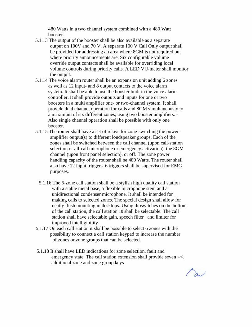
480 Watts in a two channel system combined with a 480 Watt booster.
5.1.13 The output of the booster shall be also available as a separate output on 100V and 70 V. A separate 100 V Call Only output shall be provided for addressing an area where 8GM is not required but where priority announcements are. Six configurable volume override output contacts shall be available for overriding local volume controls during priority calls. A LED VU-meter shall monitor the output.
5.1.14 The voice alarm router shall be an expansion unit adding 6 zones as well as 12 input- and 8 output contacts to the voice alarm system. It shall be able to use the booster built in the voice alarm controller. It shall provide outputs and inputs for one or two boosters in a multi amplifier one- or two-channel system. It shall provide dual channel operation for calls and 8GM simultaneously to a maximum of six different zones, using two booster amplifiers. - Also single channel operation shall be possible with only one booster.
5.1.15 The router shall have a set of relays for zone-switching the power amplifier output(s) to different loudspeaker groups. Each of the zones shall be switched between the call channel (upon call-station selection or all-call microphone or emergency activation), the 8GM channel (upon front panel selection), or off. The zone power handling capacity of the router shall be 480 Watts. The router shall also have 12 input triggers. 6 triggers shall be supervised for EMG purposes.
5.1.16 The 6-zone call station shall be a stylish high quality call station
with a stable metal base, a flexible microphone stem and a unidirectional condenser microphone. It shall be intended for making calls to selected zones. The special design shall allow for neatly flush mounting in desktops. Using dipswitches on the bottom of the call station, the call station 10 shall be selectable. The call station shall have selectable gain, speech filter _and limiter for improved intelligibility.
5.1.17 On each call station it shall be possible to select 6 zones with the possibility to connect a call station keypad to increase the number of zones or zone groups that can be selected.
5.1.18 It shall have LED indications for zone selection, fault and emergency state. The call station extension shall provide seven »<. additional zone and zone group keys

5.1.19 On each call station it shall be possible to select 6 zones with the possibility to connect up to 8 call station keypads to increase the number of zones or zone groups that can be selected. Selected zones are indicated with LEOs on the call station, three additional LEOs give visible feedback on the active state of the microphone and the system. Green indicates microphone active, amber indicates that the system has detected a fault (IEC 80649) and red indicates that the system shall be in the emergency state.
5.1.20 The power supply voltage range shall be 18 - 24V with a current consumption of less than 50 mA. The nominal sensitivity shall be 85 dB SPL (gain preset OdB). The nominal output level shall be 700 mV. The maximum allowable sound pressure level shall be 110 dBSPL. The microphone shall have a limiter. The distortion shall be less than 0.6% at maximum input. The equivalent input noise level shall be no more than 30 dBSPLA. The frequency range shall be 100Hz - 16kHz. The speech filter shall be a 315 Hz, high-pass, 6- dB/oct filter. The output impedance shall be 200 Ohms. The stem length with microphone shall be 390 mm.
5.1.21 Mains voltage shall be both 230Vac and 115Vac, ±15%, 50/ 60Hz (selectable) Power consumption of the Controller shall not exceed 600 Watts; the router shall not exceed 50Watts. Battery backup provisions shall be implemented, the battery voltage shall be 24Vdc, +20% / -10%. •
5.1.22 All low-level connections and volume override shall be on MC1,
5/XX-ST-3, 5 type connector blocks. All high level connections except mains shall be on MSTB 2,5 /XX-ST. The input contact shall have supervision based on a series and parallel resistor.
5.1.23 The router and controller shall be rack mountable with removable
rack mounts. The router shall be not higher than 2U. The controller shall be not higher than 3U. The rack mounting kit shall be included.
5.1.24 The operating temperature range shall be -10°C to +55°C. The storage temperature range shall be -40°C to + 70°C. The system should be certified with the following standards:
EVAC certified ace. to IEC 60849 EMC emission ace. to EN 55103-1 EMC immunity ace. to EN 55103-2 Safety acc. to EN 60065
The Public Address system shall be from single brand supplier.

The controller, router, call station, call station keypad, amplifier, volume control, speaker shall be from a single brand System. 6 Power Amplifiers: It shall meet the following minimum requirements: '. The main function of the power amplifier is the amplification of audio signals for. the loudspeakers. It shall be possible to select the outpu .voltaqe between 100V, 70V or 50V by changing output. The power amplifiers are provided with compact 19", 2U & 3U high housing for tabletop use and rack mounting, while the maximum amplifier wattages varies from 120w to maximums 960w. The amplifiers are protected -against overload and short circuits. A temperature- - controlled fan ensures high reliability at high output power and low acoustic noise at lower power output. Additionally, all booster amplifiers have an overheat protection circuit that switches off the power stage if the internal temperature reaches a critical limit due to poor ventilation or overload. Balanced input and a loop-through connector shall be available for easy connection of multiple booster amplifiers to increase the available output power. The power amplifier shall obtain two balanced inputs with priority control, each with a loop-through facility. This allows for easy and automatic switching between e.g. a local music source and a priority announcement from a remote system. An additional 100V line input is provided to connect the booster amplifiers to a 100V loudspeaker line, for additional output power e.g. on remote locations. Sensitivity or level control is located on the rear of the unit to avoid accidental setting change. A VU-meter with LED-bar shows the output level. The amplifiers not only provide 70V and 100V outputs for constant voltage loudspeaker systems, a low impedance output for 8 Ohm-loudspeaker loads is .. · available for different usage. The booster amplifiers operate both on mains power and on a 24V battery power supply for emergency back up, with automatic switch over. Amplifier front panel with LED shall shown as an indicator when it operates on the battery or AC supply. The power amplifier shall be with the following approval: -
• EMC emission acc. to EN 55103-1 • EMC immunity acc. to EN 55103-2 •
PERFORMANCE • Frequency response 50 Hz - 20 kHz (+1/-3 dB, @ -10 dB ref. rated output) • Distortion <1 % @ rated output power, 1 kHz INPUTS
• Line input (3-pin XLR, 6.3mm phone jack, balanced) • Sensitivity 1 V • Impedance 20 kOhm • CMRR >25 dB (50 Hz-20 kHz) ~ / • Line input 1, 2 (3-pin XLR, balanced)

• CMRR >25 dB (50 Hz-20 kHz) • 100V input (Screw, unbalanced) • Sensitivity 100 V
• Impedance 330 kOhm
OUTPUTS Line loopthrough outpu t (3-pin XLR, 6.3mm phone jack, balanced):
• Nominal level 1 V • Impedance direct connection to line input • Line loopthrough output 1,2 (3-pin XLR, balanced) • Impedance direct connection to line input • Loudspeaker outputs (Screw, floating) • Output power @ 24 V • Battery operation -1 dB ref. rated power •
ENVIRONMENTAL CONDITIONS
• Operating temperature range -10 to +550C • Storage temperature range -40 to + 700C • Relative humidity <95% •
6 Integrated Compact Disc Player with Digital Tuner The CD-player shall play normal audio CDs and CD-Rs with MP3- encoded files. The CD-player is designed to allow for high quality uninterrupted music playback from a single MP3-disc. Music shall be organized on a disc in multiple folders with music selection for different occasions, with programming facilities for up to 999 tracks. Repeat and random play modes are also provided. The digitally controlled FM/AM tuner uses a frequency synthesizer for accurate capture of radio stations and 10 presets for FM and 10 presets for AM to store favorite radio stations. Both the CD-player and the tuner operate simultaneously on different outputs to facilitate two-channel BGM distribution. 7 POWER SUPPLY 7.1 The contractor shall make provision for all necessary power supply units, voltage regulators, etc, to ensure that the equipment will perform satisfactorily c/w necessary surge arrestors and filters. 7.2 All necessary power supply (s/s/o's etc) required for the operation of the sound equipment shall be designed supplied and installed by the contractor.
8 EMERGENCY OVERRIDE UNIT

The emergency override unit when activated from the Fire Command Center, it - will override all incoming signals to allow emergency messages to pass through. 9 GUARANTEED PERIOD
9.1 The system shall be guaranteed against workmanship, installation design and manufacture defects for the period of twelve (12) months from the end of DLP. Any defective material or equipment shall be replaced as and when directed by the S.O. at no cost to the Employer.
10 SYSTEM TESTING 10.1 The contractor shall test the system in the presence of the Superintending
Officer to show that its performance satisfies the requirement of this specification, All test equipments shall be professional and supplied
by the contractor. A sound pressure meter will be required. No claim is allowed for this test. The cost shall be deemed to be included in the schedule of rates for the equipment.
1. General Description 1.1. Function and Facilities Summary 1.1.1. Building Facilities The following facilities are to be provided at building:
• PA system cabinet • Operator Control Room (OCR) Call station • Reception Call station(s) • Loudspeakers
The detailed descriptions of above mentioned equipment is described below. 1.1.2. Building Function
• Operator Control Room call station: The Security Supervisor can make an announcement to any zone or any combination of zones of that building via the OCR call station. The type of announcements, that are allowed from the OCR call station, are:
• Live announcements • Pre-recorded announcements • Background music • Pre-recorded emergency announcements
• Reception Control Panel Announcements: At the reception control panel, the operator can make live announcements to that building with pre-defined areas.
• Emergency Announcements: The pre-recorded announcements can be initiated by the fire alarm signal that is sent from the fire alarm system
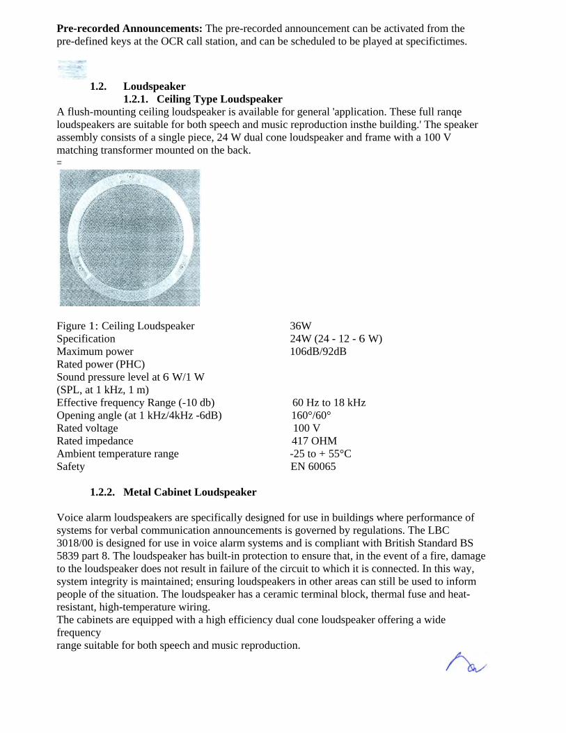
Pre-recorded Announcements: The pre-recorded announcement can be activated from the pre-defined keys at the OCR call station, and can be scheduled to be played at specifictimes.
1.2. Loudspeaker 1.2.1. Ceiling Type Loudspeaker A flush-mounting ceiling loudspeaker is available for general 'application. These full ranqe loudspeakers are suitable for both speech and music reproduction insthe building.' The speaker assembly consists of a single piece, 24 W dual cone loudspeaker and frame with a 100 V matching transformer mounted on the back. =
Figure 1: Ceiling Loudspeaker 36W Specification 24W (24 - 12 - 6 W) Maximum power 106dB/92dB Rated power (PHC) Sound pressure level at 6 W/1 W (SPL, at 1 kHz, 1 m) Effective frequency Range (-10 db) 60 Hz to 18 kHz Opening angle (at 1 kHz/4kHz -6dB) 160°/60° Rated voltage 100 V Rated impedance 417 OHM Ambient temperature range -25 to + 55°C Safety EN 60065 1.2.2. Metal Cabinet Loudspeaker Voice alarm loudspeakers are specifically designed for use in buildings where performance of systems for verbal communication announcements is governed by regulations. The LBC 3018/00 is designed for use in voice alarm systems and is compliant with British Standard BS 5839 part 8. The loudspeaker has built-in protection to ensure that, in the event of a fire, damage to the loudspeaker does not result in failure of the circuit to which it is connected. In this way, system integrity is maintained; ensuring loudspeakers in other areas can still be used to inform people of the situation. The loudspeaker has a ceramic terminal block, thermal fuse and heat-resistant, high-temperature wiring. The cabinets are equipped with a high efficiency dual cone loudspeaker offering a wide frequency range suitable for both speech and music reproduction.

_ Figure 3: Metal Cabinet Loudspeaker Specification Maximum power Rated power (PHC) Sound pressure level at rated power6 W/1 W (SPL, at 1 kHz, 1 m) Effective frequency range (-10 dB) Opening angle (at 1 kHzl4 kHz, -6 dB) Rated voltage _ Rated impedance Ambient temperature range
9W 6 W (6 -3 - 1.5 W) 102 dB/94 dB 150 Hz to 20 kHz 120°/55° 100 V 16670 -25 to +55°C
1.2.3.
Prosound Cabinet Loudspeaker
The LBC 3800/10 100 W stage loudspeaker is compact yet powerful. Its excellent sound reproduction capability is attributed to the use of arrayed professional quality components. It contains a high-quality 12" woofer with a 1-3/8" voice coil titanium high-frequency driver, linked via a special crossover/equalizer network for optimal sound reproduction. A self-restoring passive element protects the-tuqh-trequency-criver-acatnst incidental overload:
Figure 4: 100W Cabinet Loudspeaker
Specification Loudspeaker Type 2-way speaker system Rated Power (PHC) 100W Long-Term Input Power 200W Short-Term Input Power 250W

Sound Pressure Level at 118 dB/98 dB 100 W/1 W (at 1 kHz, 1 m) Effective Freq. Range (-10 dB) 70 Hz to 20 KHz Crossover Frequency 3.5 kHz (-12 dB) Opening Angle (at 1 kHzl4 kHz, -6 dB) Horizontal 110°/65° Vertical 110° I 75° Rated Voltage 100 V Rated Impedance 100 ohm Ambient Temperature -25 to +55°C (-13 to 131°F) 1.3. Background ~music Source -e The CD-player is a high quality source unit, comprising a CD-player with single CD slot loading. The track selection keys of the CD-player include Random and Repeat to facilitate BGM (background music) operation. The CD-player operates in mono, as required for BGM, and simultaneously on different outputs, to facilitate two-channel BGM distribution. The output level can be adjusted via rear panel presets.
Figure 5: Background Music Source Specifications Mains voltage 230Vac/115Vac, ±15%, 50/60Hz Max mains power consumation 25VA CD-PLAYER Performance 20Hz - 20 kHz (+1/-3dB) Frequency response Distortion <0.1% SIN 85dB OUTPUTS CD-player output (Cinch, 2 x mono) Nominal level 500mV ENVIRONMENTAL CONDITIONS Operating temperature range -10 to +55°C Storage temperature range -40 to + 70°C Relative humidity <95% EMC emission acc. to EN 55103-1 EMC immunity ace. to EN 55103-2 19" mounting brackets included

1.4. Voice Alarm Controller: -
Figure 6: Voice Alarm Controller Technical Specifications 230/115 VAC, ±10%, 50/60 Hz Electrical 60 VA Mains Voltage 360 W / 240 W Main Power Consumption Max/Rated Output Power Mains Current System Idle 0.26 A = 60 VA System Idle with Pilot Tone 0.6 A = 136 VA Maximum Load*) 3.6 A = 830 VA 24 V Current System Idle 0.9A Maximum Load* 14 A Performance Frequency Response 60 Hz -18 kHz (+1/-3 dB, @ -10 dB ref. rated output) Distortion <1 % @ rated output, 1 kHz Bass Control -8/+8 dB @ 100 Hz Treble Control -8/+8 dB @ 10kHz Inputs Mic / Line Input Type XLR, 6.3 mm jack Sensitivity 1 mV /1V SIN 75 dB (flat at min volume/muted) SIN 25 dB Headroom -3 dB@ 315 Hz, high-pass, 6 dB/oct Speech Filte Phantom Power Supply 12 V VOX Trigger Level -20 dB (100 V mic /100 mV line) or via Automatic Limiter BGM and PC Call Station Cinch stereo (converted to mono) Input Level 200 mV -2 V Impedance 22 kOhm SIN 70 dB (flat at max volume) SIN 75 dB (flat at min volume/muted) Headroom 25 dB Trigger Inputs 6 EMG, 6 business Type MC1,5/14-ST-3,5 Activation Programmable Supervision On EMG inputs, programmable

Supervision Method Series 1 parallel resistor 100 V Input MSTB 2,5/16-ST Power Handling Capacity 480 Watts *) Maximum load means; maximum power out, maximum load 24V out, maximum number of Call stations 1.5. Router: -
Figure 7: Router TechnicalSpecification Electrical Mains Voltage Max Mains Power Max Mains Inrush Trigger Inputs Activation Supervision Supervision Method 100 V Inputs Booster 1 Booster 2 Power Handling Capacity Outputs 100 V / 70 V Outputs 100 V Outputs Volume Override Output Contacts All Contacts Connector Type Rating General Purpose Relays (2x) Environmental Operating Temperature Storage Temperature Relative Humidity Dimensions Rack Building
230 VAC / 11S VAC, ±1S%, SO 160 Hz 5O VA 1.5A@230VAC/3A@115VAC 6 EMG, 6 business Programmable On EMG inputs, programmable Series 1 parallel resistor MSTB 2,5/16-ST 100 V 1 70 V 1 0 V 100 VI 0 V 1000 Watts MSTB 2,5/16-5T, floating 1000 W rated per zone Type 3 wire, 4 wire (24 V), 4 wire failsafe MC1,5/12-ST-3,5 250 V 7 A voltage free NO/COM +5°C to +55°C -25°C to +55°C <95% 88 x 430 x 260 mm (19" wide, 2U high) Rack mounting kit included

1.6. Call Station: - Technical Specifications Electrical Power Supply Voltage Range Current Consumption Performance Nominal Sensitivity Nominal Output Level Maximum Input Sound Level Gain Preset Limiter Threshold Compression Ratio Limiter Distortion Equivalent Input Noise Level Frequency Response Speech Filter Output Impedance Selections Environmental Operating Temperature Storage Temperature Relative Humidity 1.7. Amplifiers: -
Figure 8: Call Station 18 - 24 V <30 mA Call Station <15 mA Key Pad 85 dB SPL (gain preset 0 dB) 700 mV 110dBSPL +6/0/-15dB 2V 20: 1 <0.6% (maximum input) 25 dB SPLA 100 Hz - 16 kHz -3 dB' @ 315 Hz, high-pass, 6 dB/oct 200 ohms -10°C to +55°C -40°C to + 70°C <95%
Figure 9: Amplifier
Fre
quency Response

BUilding Operations Function
1.8.1. Building Zoning The building is divided into several zones, dependant upon the physical arrangement of the building. 1.8.2. Building Operation 1.8.2.1.
Normal Operation
OCR Call Station The OCR call station allows the building supervisor to broadcast an announcement to any zone or combination of zones within the building. The destination zones can be selected at the zone selection keys at the call station. The status of the zone is indicated by an LED when that zone is selected. The zone selection keys operate in latching mode. The announcements, to the selected zones, can be initiated by pressing the 'press to talk' key at the call station throughout the announcement. The 'press to talk' status LED indicates the status of the announcement. . The pre-recorded announcement can be activated from the pre-defined keys at the OCR call station, and can be scheduled to be played at specific times. The background music can be activated by the 'Back Ground Music' key, which operates in latching mode and the status of the background music key is indicated by an LED. Reception Call Station The reception call station allows the operator to generate announcements to the associated areas. The call can be initiated by pressing the 'press to talk' key at the reception microphone throughout the announcement. The status of the reception call station will-be given by means of LED. Announcements from the reception call station can override the OCR announcements. 1.8.2.2. Emergency Operation In the event of emergency, i.e. fire, the PA system will receive fire alarm signal from the fire alarm system to initiate the pre-recorded emergency announcement to peoples and staff in the building. The PA system will address all zones within that building with the emergency message. In the event that the PA system fails to receive the fire alarm signal, the emergency messages can be activated/ deactivated the OCR call station. The emergency announcement can be overridden by an announcement from the OCR and reception call stations. 1.8.3. Priority The priority of announcements in the building is as follows:

2.1. Interfacing to Fire Alarm System The PA system requires the fire alarm signal from the fire alarm system at building to initiate the pre-recorded emergency announcement. The means of interface is a single dry contact from the fire alarm system to the alarm input at the PA system cabinet at control room. The contact is normally close, which means that the contact will be opened when the fire alarm system sends alarm signal to the PA system and the contact will open when there is no fire alarm signal from the fire alarm system. In the event that the fire alarm system fails to send the alarm signal to the PA system, the operator can either initiate the pre-recorded emergency announcement or make a live announcement manually at the OCR call station for the building, the broadcast may be made manually from the appropriate administration office. Cable and Wiring 3.1. Loudspeaker Cable The loudspeaker cable connected from power amplifiers to the loudspeakers operates at 100 volts. The generic type of cable shall be .8. The building is divided into several zones, building.

1.8.2. Building Operation
.- 80 dB 4 ohm, 8 ohm, 70 V, 100 V dependant upon the physical arrangement of the
1.8.2.1. Normal Operation
OCR Call Station The OCR call station allows the building supervisor to broadcast an announcement to any zone or combination of zones within the building. The destination zones can be selected at the zone selection keys at the call station. The status of the zone is indicated by an LED when that zone is selected. The zone selection keys operate in latching mode. The announcements, to the selected zones, can be initiated by pressing the 'press to talk' key at the call station throughout the announcement. The 'press to talk' status LED indicates the status of the announcement. - The pre-recorded announcement can be activated from the pre-defined keys at the OCR call station, and can be scheduled to be played at specific times. The background music can be activated by the 'Back Ground Music' key, which operates in latching mode and the status of the background music key is indicated by an LED. Reception Call Station The reception call station allows the operator to generate announcements to -the associated areas. The call can be initiated by pressing the 'press to talk' key at the reception microphone throughout the announcement. The status of the reception call station will-be given by means of LED. Announcements from the reception call station can override the OCR announcements. 1.8.2.2. Emergency Operation In the event of emergency, i.e. fire, the PA system will receive fire alarm signal from the fire alarm system to initiate the pre-recorded emergency announcement to peoples and staff in the building. The PA system will address all zones within that building with the emergency message. In the event that the PA system fails to receive the fire alarm signal, the emergency messages can be activated/ deactivated the OCR call station. The emergency announcement can be overridden by an announcement from the OCR and reception call stations.

1.8.3. Priority The priority of announcements in the building is as follows: Local announcement from the OCR call station and the reception call station Local emergency broadcasts from pre-recorded emergency announcements Timed local broadcasts
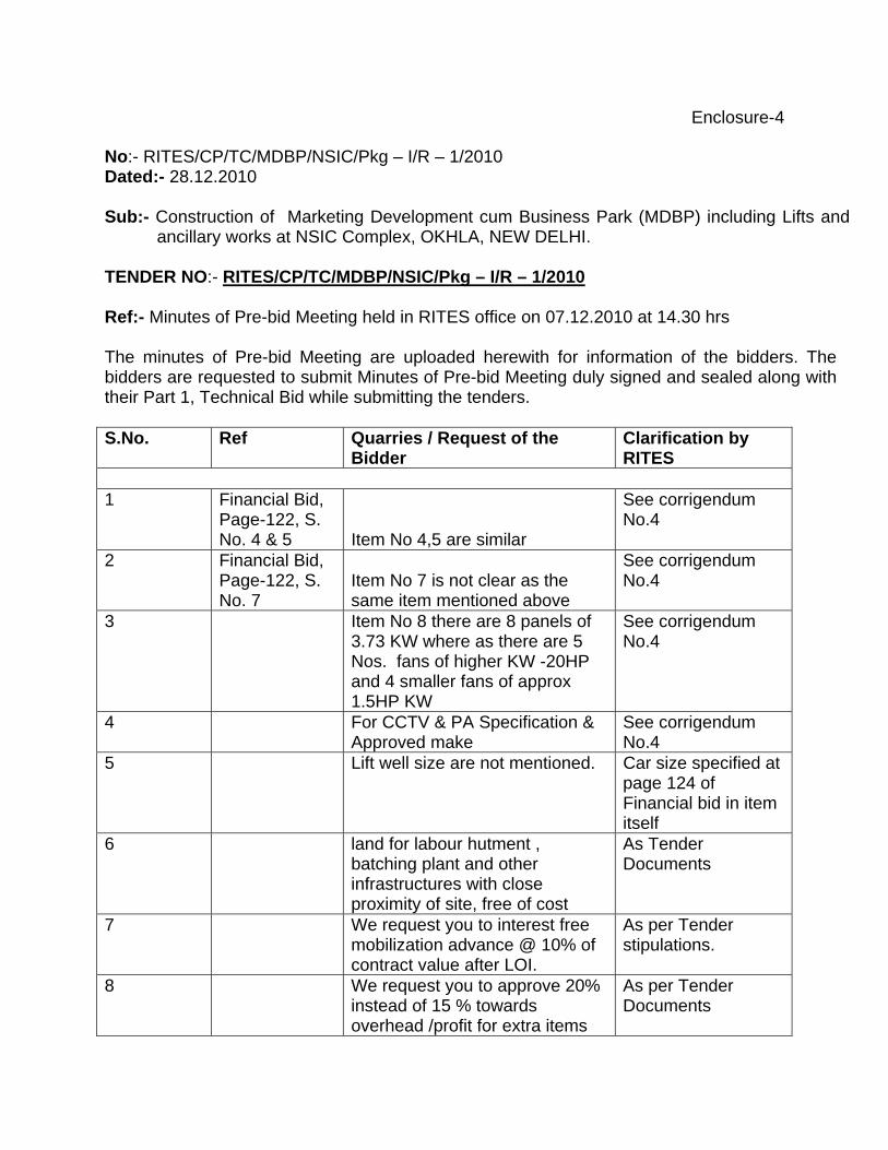
Enclosure-4 No:- RITES/CP/TC/MDBP/NSIC/Pkg – I/R – 1/2010 Dated:- 28.12.2010 Sub:- Construction of Marketing Development cum Business Park (MDBP) including Lifts and
ancillary works at NSIC Complex, OKHLA, NEW DELHI. TENDER NO:- RITES/CP/TC/MDBP/NSIC/Pkg – I/R – 1/2010 Ref:- Minutes of Pre-bid Meeting held in RITES office on 07.12.2010 at 14.30 hrs The minutes of Pre-bid Meeting are uploaded herewith for information of the bidders. The bidders are requested to submit Minutes of Pre-bid Meeting duly signed and sealed along with their Part 1, Technical Bid while submitting the tenders. S.No.
Ref Quarries / Request of the Bidder
Clarification by RITES
1 Financial Bid,
Page-122, S. No. 4 & 5 Item No 4,5 are similar
See corrigendum No.4
2 Financial Bid, Page-122, S. No. 7
Item No 7 is not clear as the same item mentioned above
See corrigendum No.4
3 Item No 8 there are 8 panels of 3.73 KW where as there are 5 Nos. fans of higher KW -20HP and 4 smaller fans of approx 1.5HP KW
See corrigendum No.4
4 For CCTV & PA Specification & Approved make
See corrigendum No.4
5 Lift well size are not mentioned. Car size specified at page 124 of Financial bid in item itself
6 land for labour hutment , batching plant and other infrastructures with close proximity of site, free of cost
As Tender Documents
7 We request you to interest free mobilization advance @ 10% of contract value after LOI.
As per Tender stipulations.
8 We request you to approve 20% instead of 15 % towards overhead /profit for extra items
As per Tender Documents

S.No.
Ref Quarries / Request of the Bidder
Clarification by RITES
excluding taxes as applicable. 9 Please provide free of cost water
and if it is not possible please allow us to do bore well at site for construction and other related water purpose.
As per Tender Documents.
10 We consider that all necessary approvals from Govt .bodies /authorities will be taken care of by client /PMC only
As per Tender documents
11 We request you to confirm the mobilization period
As per tender Documents
12 We request you to confirm the colour of Granite, vitrified tiles/Granite Stone.
As per sample Approval of Engineer-in-charge .
13 We request you to accept EMD in BG format.
AS per Tender Stipulations
14 Security Deposit /COC SEC 4/Cl 1A & COC/Sec 4/Cl 17
We request you to accept SD in BG the format instead of cash retention.
As per Tender Document.
15 EMD NIT & ITT Sec 1 /Cl9
We request you to accept EMD in BG format.
AS per tender documents
16 Compensation for delay COC /Sec 4 Cl 2
Please reduce LD rate to .2 % v per week of delay with limitation of maximum LD to 5% of CP. .instead of 1 % of contract value/week of delay subject to maximum of 10% of CP .
As per tender documents
17 Escalation -Sec 11/sch A & F/Cl10cc
Please provide basic rates for cement and steel as there is no escalation provision in tender considering fluctuation in market rates.
As per tender conditions.
18 Service Tax -COC Section 4 /CL 37
We presume service tax is not applicable if applicable it will be reimbursed by the contractor
As per Tender Documents and corrigendum.
19 Please make provision in tender for compensation for change in taxes due to statutory changes after submission of tender.
As per Tender documents.
20 We presume that land for site office, store fabrication yard &
As per Tender Document.

S.No.
Ref Quarries / Request of the Bidder
Clarification by RITES
batching plant will be provided to us free of cost.
21 Interest on mobilization advance-COC Section- 4 /Clause 10B (ii)
Please consider to provide interest free mobilization advance or at least at reduce intrest rate of 10 %.Also provide plant and machniary advance of 10% of project cost considering list miminum plant & equipment.
As per Tender Document.
22 Water supply & electricity
Please provide free of cost water and electricity supply.
As per Tender Document.
23 List of equipment Section- 11, Clause 18
Minimum equipment list seems to be very much on higher side. Please leave it to contractor to plan requirement of equipments for the work based on his work methodology & construction schedule. Please reduce 60cum batching plant to 30cum/hr capacity, no of transit mixer and dumpers.
As per Tender Document.
24 Built up area Please provide floor wise built up area.
Covered Area of Building is as under: SQM Basement- 8134.15 G/Floor -7395.14 Ist /Floor -5980.00 IInd /Floor -6314.67 IIIrd/Floor -6274.96 IV th /Floor – 5175.71 V th /Floor – 5474.38
25 Submission date
Request you to please grant us an extension of at least 15 days from the scheduled date of submission.
See RITES’ web site.
26 We presume excavated earth will be dumped within site premises.
1. Within premises.
2. If outside item of lead is there.
27 Provide sizes of wooden frames, doors & windows. Clerestory windows and other frames.
See corrigendum-4
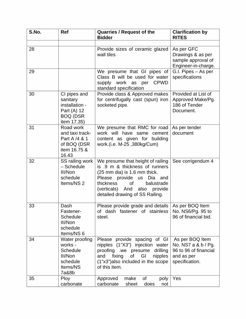
S.No.
Ref Quarries / Request of the Bidder
Clarification by RITES
28 Provide sizes of ceramic glazed
wall tiles As per GFC Drawings & as per sample approval of Engineer-in-charge.
29 We presume that GI pipes of Class B will be used for water supply work as per CPWD standard specification
G.I. Pipes – As per specifications
30 CI pipes and sanitary installation - Part (A) 12 BOQ (DSR item 17.35)
Provide class & Approved makes for centrifugally cast (spun) iron socketed pipe.
Provided at List of Approved Make/Pg. 186 of Tender Document.
31 Road work and taxi track- Part A /4 & 1 of BOQ (DSR item 16.75 & 16.43
We presume that RMC for road work will have same cement content as given for building work.(i.e. M-25 ,380kg/Cum)
As per tender document
32 SS railing work – Schedule III/Non schedule Items/NS 2
We presume that height of railing is .9 m & thickness of runners (25 mm dia) is 1.6 mm thick. Please provide us Dia and thickness of balustrade (verticals) And also provide detailed drawing of SS Railing.
See corrigendum 4
33 Dash Fastener- Schedule III/Non schedule Items/NS 6
Please provide grade and details of dash fastener of stainless steel.
As per BOQ Item No. NS6/Pg. 95 to 96 of financial bid.
34
Water proofing works - Schedule III/Non schedule Items/NS 7a&8b
Please provide spacing of GI nipples (1”X3”) injection water proofing .we presume drilling and fixing of GI nipples (1”x3”)also included in the scope of this item.
As per BOQ Item No. NS7 a & b / Pg. 96 to 96 of financial and as per specification.
35 Ploy carbonate
Approved make of poly carbonate sheet does not
Yes

S.No.
Ref Quarries / Request of the Bidder
Clarification by RITES
sheet (Schedule III/Non schedule Items/NS 22,23,24
include Gallina but Gallina make is specified in the BOQ description .We presume Gallina is also approved agency in addition to approved list .please confirm
36 MS frame work for Ploy carbonate sheet (Schedule III/Non schedule Items/NS 22,23,24
We presume MS frame is not included in NS items 22 & 23 and same would be paid separately as per item 24
Yes
37 Ploy carbonate sheet (Schedule III/Non schedule Items/NS 22,23,24
Please provide detailed drawing of Ploy carbonate sheet roofing showing details of MS frame, support details, curvature of dome sky light.
As per manufacturers’ design/specifications and as per site requirement.
38 doors & windows
Please provide detailed doors and windows schedule for typical floors.
See corrigendum 4.
39 Lift Work Part II, lift work/section VI- item No 1&2
In lift section for 20 passenger elevator with five side glass is presently not available Otis. But available up to three side glass. shall we quote the three side panels for 20 passenger lifts.
See corrigendum 4.
40 EMD We request you to accept EMD in BG format instead of DD.
AS per tender Documents
41 Service Tax Is applicable or not for this project please clarify
AS per tender Documents
42 Space for batching plants and labour hutments
Spaces for batching plant are available or not please clarify. In tender document mentioned that contractor shall arrange the space for labour hutment .but if client provide spaces for that purpose work can be accomplished easily.
AS per tender Documents
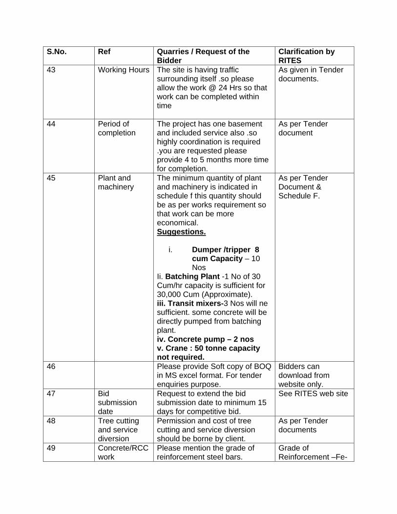
S.No.
Ref Quarries / Request of the Bidder
Clarification by RITES
43 Working Hours The site is having traffic surrounding itself .so please allow the work @ 24 Hrs so that work can be completed within time
As given in Tender documents.
44 Period of completion
The project has one basement and included service also .so highly coordination is required .you are requested please provide 4 to 5 months more time for completion.
As per Tender document
45 Plant and machinery
The minimum quantity of plant and machinery is indicated in schedule f this quantity should be as per works requirement so that work can be more economical. Suggestions.
i. Dumper /tripper 8 cum Capacity – 10 Nos
Ii. Batching Plant -1 No of 30 Cum/hr capacity is sufficient for 30,000 Cum (Approximate). iii. Transit mixers-3 Nos will ne sufficient. some concrete will be directly pumped from batching plant. iv. Concrete pump – 2 nos v. Crane : 50 tonne capacity not required.
As per Tender Document & Schedule F.
46 Please provide Soft copy of BOQ in MS excel format. For tender enquiries purpose.
Bidders can download from website only.
47 Bid submission date
Request to extend the bid submission date to minimum 15 days for competitive bid.
See RITES web site
48 Tree cutting and service diversion
Permission and cost of tree cutting and service diversion should be borne by client.
As per Tender documents
49 Concrete/RCC work
Please mention the grade of reinforcement steel bars.
Grade of Reinforcement –Fe-

S.No.
Ref Quarries / Request of the Bidder
Clarification by RITES 500
50 Wood work Item No 47/9.1.1 a II nd class teak wood as per DSR 2007 but in the item sal wood is specified in item .please clarify
See Corrigendum 4.
51 Flooring Work The rates of vitrified tiles and granite stone depends upon their colour .please provide the colours of the same material. 100 X100 cm tiles are normally not available please change to 60X60cm
As per Tender Documents..
Rest all terms and conditions will remain unchanged.


