nasa's recommendations to space-faring entities: how to protect
TRANSCRIPT
National Aeronautics and Space Administration
1
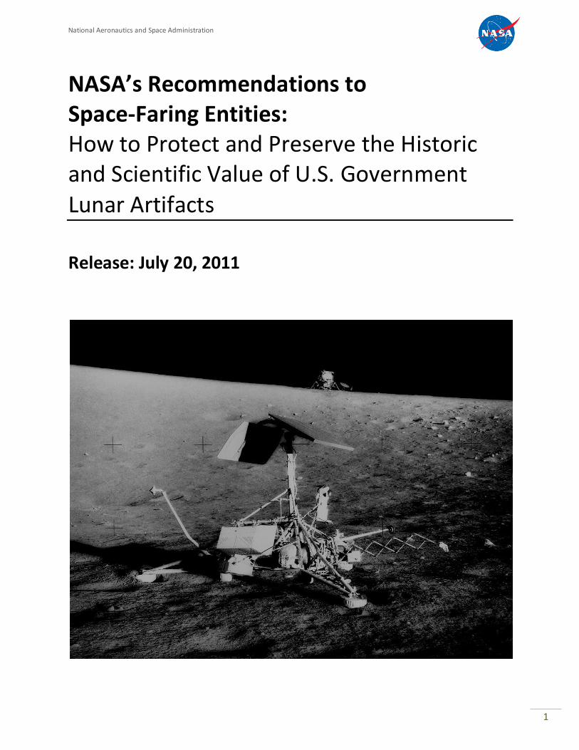
NASA’s Recommendations to Space-Faring Entities: How to Protect and Preserve the Historic and Scientific Value of U.S. Government Lunar Artifacts
Release: July 20, 2011
National Aeronautics and Space Administration
2
Revision and History Page
Status Revision No. Description Release Date
Release Baseline Initial Release 07/20/2011
Update Rev A Updated with imagery from Apollo missions 12, 14-17. Added Appendix D: Available Photo Documentation of Apollo Hardware
10/28/2011
National Aeronautics and Space Administration
3
HUMAN EXPLORATION & OPERATIONS MISSION DIRECTORATE STRATEGIC ANALYSIS AND INTEGRATION DIVISION
NASA HEADQUARTERS
NASA’S RECOMMENDATIONS TO SPACE-FARING ENTITIES: HOW TO PROTECT AND PRESERVE HISTORIC AND SCIENTIFIC VALUE OF U.S. GOVERNMENT ARTIFACTS
THIS DOCUMENT, DATED JULY 20, 2011, CONTAINS THE NASA RECOMMENDATIONS AND ASSOCIATED RATIONALE FOR SPACECRAFT PLANNING TO VISIT U.S. HERITAGE LUNAR SITES. ORGANIZATIONS WITH COMMENTS, QUESTIONS OR SUGGESTIONS CONCERNING THIS DOCUMENT SHOULD CONTACT NASA’S HUMAN EXPLORATION & OPERATIONS DIRECTORATE, STRATEGIC ANALYSIS & INTEGRATION DIVISION, NASA HEADQUARTERS, 202.358.1570.

National Aeronautics and Space Administration
4
Table of Contents
REVISION AND HISTORY PAGE 2
TABLE OF CONTENTS 4
SECTION A1 – PREFACE, AUTHORITY, AND DEFINITIONS 5 PREFACE 5 DEFINITIONS 7 A1-1 DISTURBANCE A1-2 APPROACH PATH A1-3 DESCENT/LANDING (D/L) BOUNDARY A1-4 ARTIFACT BOUNDARY (AB) A1-5 VISITING VEHICLE SURFACE MOBILITY A1-6 OVERFLIGHT A1-7 CONTAMINATION A1-8 REFERENCE SYSTEM A1-9 EXCLUSION ZONE
BOUNDARY (VVSMB)
7 7 7 8 8 8 8 9 9
SECTION A2 – DESCENT AND LANDING (D/L) 10 RECOMMENDATIONS FORMAT 10 TARGETING 10 A2-1 APPROACH PATH A2-2 NO OVERFLIGHT A2-3 TOUCHDOWN TARGETING A2-4 DISPOSAL OF BRAKING STAGE(S) A2-5 USE OF NATURAL TERRAIN BARRIERS A2-6 COLLISION AVOIDANCE WINDOWS A2-7 LANDER ORIENTATION FOR FINAL APPROACH/LANDING
RELATIVE TO THE U.S.HERITAGE SITE (MULTI-ENGINES DESCENT CASE)
10 11 11 14 14 15
16
SECTION A3 – MOBILITY 17 ROVERS/HOPPERS/EXCLUSION ZONES A3-1 GENERAL OVERVIEW – HISTORICAL PERSPECTIVE A3-2 EXCLUSION ZONE – APOLLO 11 & 17 SITES A3-3 EXCLUSION ZONE – APOLLO 12, 14-16 SITES A3-5 EXCLUSION ZONE – IMPACT SITES A3-6 EXCLUSION ZONE – ROVERS AT APOLLO SITES A3-7 LINEAR WHEEL SPEED OF ROBOTIC ROVERS A3-8 BACK-TRACKING A3-9 HOPPERS AT APOLLO SITES A3-10 LOW-ALTITUDE FLY-BY OF APOLLO SITES
PER APOLLO SITE 17 17 17 19 25 26 26 27 27 28
SECTION A4 – CONTAMINATION 30 A4-1 PHYSICAL CONTACT A4-2 DUST A4-3 UN-BURNED/RESIDUAL PROPELLANTS A4-4 PLANETARY PROTECTION A4-5 BIOLOGICAL
30 30 30 31 31
APPENDIX A – ACRONYMS 33
APPENDIX B – NASA ENGINEERING / SAFETY APOLLO ARTIFACTS AS WITNESS PLATES
CENTER (NESC) EVALUATION OF 34
APPENDIX C – NASA LUNAR SCIENCE ASSESSMENT OF APOLLO SITES AS WITNESS PLATES 47
APPENDIX D – AVAILABLE PHOTO DOCUMENTATION OF APOLLO HARDWARE 53
APPENDIX E – APOLLO MISSIONS LUNAR ASSETS 76
National Aeronautics and Space Administration
5
SECTION A1 – PREFACE, AUTHORITY, AND DEFINITIONS
PREFACE NASA recognizes the steadily increasing technical capabilities of space-faring commercial entities and nations throughout the world and further recognizes that many are on the verge of landing spacecraft on the surface of the moon. Representatives of commercial entities have contacted NASA seeking guidance for approaching U.S. Government (USG) space assets on the lunar surface – out of respect for hardware ownership, and a sincere desire to protect general scientific and historic aspects of these sites. Because there is no precedent for this situation throughout nearly 50 years of spaceflight, there are no USG guidelines or requirements for spacecraft visiting the areas of existing USG-owned lunar hardware regardless of condition or location. Fortunately, there are several lunar experts across NASA and the scientific, historical, legal, materials, and flight-planning communities who can provide some initial guidance for these lunar endeavors. NASA has performed recent propellant/plume and lunar regolith impingement analyses and initiated a science evaluation that examined the risks and concerns of damage to the heritage Apollo landing sites resulting from future spacecraft descent/landing and associated surface and low-altitude flight mobility. From a scientific perspective, many sites are still active (e.g., Apollo retro-reflectors), and continue to produce material, biological, and physical scientific data associated with long-term exposure of human-created systems (e.g., witness plates) to the lunar environment. NASA has also considered impacts to non-Apollo USG lunar artifacts. Until more formal USG guidance is developed and perhaps a multilateral approach is developed to reflect various nations’ views on lunar hardware of scientific and historic value, NASA has assembled this document that contains the collected technical knowledge of its personnel – with advice from external experts and potential space-faring entities – and provides interim recommendations for lunar vehicle design and mission planning teams. As such, this document does not represent mandatory USG or international requirements; rather, it is offered to inform lunar spacecraft mission planners interested in helping preserve and protect lunar historic artifacts and potential science opportunities for future missions.
These recommendations are intended to apply to USG artifacts on the lunar surface – these artifacts include:
A. Apollo lunar surface landing and roving hardware; B. Unmanned lunar surface landing sites (e.g., Surveyor sites); C. Impact sites (e.g., Ranger, S-IVB, LCROSS, lunar module [LM] ascent stage); D. USG experiments left on the lunar surface, tools, equipment, miscellaneous EVA
hardware; and E. Specific indicators of U.S. human, human-robotic lunar presence, including footprints,
rover tracks, etc., although not all anthropogenic indicators are protected as identified in the recommendations.
Because of the relevance of these recommendations to current and future lunar elements deposited by other space-faring entities, NASA has begun engaging in dialogue with foreign space agencies, as appropriate.
National Aeronautics and Space Administration
6
LEGAL FRAMEWORK
The USG continues to maintain ownership of NASA hardware and other property on the surface of the moon, including the Apollo artifacts. These recommendations are not legal requirements; rather they are technical recommendations for consideration by interested entities. NASA seeks coordination in advance of lunar activities that would impact NASA artifacts of historic and scientific interest to ensure that all appropriate interests are recognized and protected. NASA recognizes that these recommendations may evolve and welcomes the opportunity to work with foreign space agencies and other entities planning robotic lunar missions. As part of the USG, NASA is committed to meetings USG responsibilities under international law. U.S. law authorizing NASA to make these recommendations include the following:
National Aeronautics and Space Administration Act
2010 NASA Authorization Act
United States Constitution --“Property Clause”
Federal Property and Administrative Services Act of 1949, as amended
General Services Administration Regulations
18 U.S.C. 7
These recommendations are consistent with international law, including the following: The 1967 U.N. Outer Space Treaty (OST), which provides, in part:
That outer space shall be free for exploration and use by all states;
That there should be freedom of scientific investigation in outer space;
That outer space is not subject to national appropriation;
That parties to the treaty retain jurisdiction and control over objects launched into outer space that are listed on their registries, while they are in outer space and that ownership of objects launched into outer space is not affected by their presence in outer space or by their return to Earth;
That nations be guided by the principle of cooperation and mutual assistance in lunar exploration and use, with due regard to the corresponding interests of other parties to the treaty; and
That international consultations must take place prior to the commencement of an activity that any party has reason to believe would cause potentially harmful interference with activities of other parties.
APPROACH: NASA is seeking to promote the development and implementation of appropriate recommendations, such as those provided herein, with interested private sector entities and, as appropriate, working within the USG and with foreign governments.
National Aeronautics and Space Administration
7
DEFINITIONS
A1-1 DISTURBANCE
The term “disturbance” in this context means: to effect a change or perturbation to the site artifacts resulting in loss of historic and scientific processes and information. Some spacecraft operations, like descent/landing or overflight, can result in significant damage to the site artifacts; while other operations (e.g., a rover traversing an Apollo site) could result in significant loss to the scientific value of the site.
RATIONALE: Since the completion of the Apollo lunar surface missions in 1972, no missions have returned to visit these historic sites, leaving them in pristine condition and undisturbed by artificial processes (the sites have changed due to normal space weathering). It is anticipated that future spacecraft will have the technology and their operators will have the interest to visit these sites in the coming years. These visits could impose significant disturbance risks to these sites, thus potentially destroying irreplaceable historic, scientific and educational artifacts and materials. A site may include multiple areas of interest, depending upon the specific mission. For example, the Apollo 11 site can be easily included within a single boundary whereas the Apollo 17 site, with additional mobility provided by the lunar rover, may include multiple boundaries around the landing area as well as around each of the traverse sampling sites.
A1-2 APPROACH PATH The ‘approach path’ is defined as the intended path of the spacecraft, plus the width of the three-sigma dispersion for the path.
A1-3 DESCENT/LANDING (D/L) BOUNDARY
The D/L boundary is defined as the outer perimeter that establishes an exclusion radius for the approach path of any lander/spacecraft toward any USG heritage lunar site.
For heritage lander sites (e.g., Apollo, Surveyor): This boundary thus defines an area beginning at the lunar surface site of interest and extending to a 2.0 km radial distance from the site where no overflight of a landed spacecraft may occur.
For the heritage impact sites (e.g., Ranger, S-IVB): This boundary thus defines an area beginning at the lunar surface site of interest and extending to a 0.5 km radial distance from the center of the impact site where no overflight of a landed spacecraft may occur.
This boundary prevents the plane of the descent trajectory from crossing into the exclusion radius at any point during the descent, thus remaining tangential to the boundary. It is incumbent on each visiting spacecraft to ensure no intrusion into this boundary during descent and landing, including nominal and off-nominal operations.
RATIONALE: The 2.0 km exclusion radius applies to the descent/approach path of the visiting vehicle to address three main concerns during descent:

National Aeronautics and Space Administration
8
1. Overflight – possibility of creating high-velocity particles during descent, directly
impinging plume on the heritage site 2. Near overflight – exhaust-blown dust onto the site 3. System failure during descent – collision potential / dust creation
The first two scenarios occur near the surface, and the ejecta flux protection of the 2.0 km touchdown exclusion radius will prevent those.
For the third scenario: In case of a complete loss of thrust, the instantaneous impact point (IIP) of the vehicle lies in the plane of the trajectory. Generally the IIP lies downrange of the landing target, but there are some cases in which it is up-range, depending on the descent trajectory. A reasonable constraint would be to require that the plane of the descent trajectory not cross into a similar type of exclusion radius at any point during the descent. This requirement would cover the overflight concerns (1 and 2 above) as well.
With reference to the impact sites, a 0.5 km distance is selected to allow closer D/L targeting than is allowed for the USG heritage lander sites (Apollo, Surveyor). The heritage lander sites have flight hardware that is elevated above the lunar surface, exposing it to high-velocity particle impacts created by the descent engines. However, the impacts sites sit much farther below the surface terrain and are less likely to be damaged by the ejecta particles resultant from the arrival of the visiting vehicle.
A1-4 ARTIFACT BOUNDARY (AB)
The AB will be established to specifically encompass all artifacts at a particular site to prohibit interaction/visitation within that area in order to protect the artifacts of interest: descent stage, lunar rover, flag, Apollo Lunar Surface Experiments Package (ALSEP) experiments, etc.
A1-5 VISITING VEHICLE SURFACE MOBILITY BOUNDARY (VVSMB)
The VVSMB defines the specific areas for each heritage site where surface mobility is recommended to assess/examine the artifacts of the site without disturbing the site/artifact and without directly contacting any of the hardware in the AB. The surface mobility boundary will be determined to allow the maximum recommended access for scientifically assessing the artifacts of the site while ensuring minimal disturbances. These boundary conditions will vary by site, depending on the site’s historic value, and will contain the artifacts within the specified artifacts boundary areas.
A1-6 OVERFLIGHT
Overflight is defined as the specific flight path of an entering spacecraft or braking stage that results in a trajectory over the heritage site (D/L boundary).
A1-7 CONTAMINATION
Contamination is the act of depositing chemical, biological or physical material onto artifacts at the heritage site such that the deposition reduces its historical, engineering, or scientific value. Contamination can take on several forms, including surface particulate, non-volatile residue, volatile hydrocarbons, and microbial.
National Aeronautics and Space Administration
9
Analysis of returned Surveyor 3 spacecraft parts showed chemical contamination from Apollo 12 LM exhaust compounds (Reference: NASA-SP-284, 1972).
A1-8 REFERENCE SYSTEM
Each lunar spacecraft should have an onboard reference system to identify the physical location description of the D/L, AB and VVSMB. Such a reference system will assist in ensuring that all visiting spacecraft have knowledge of the identified boundaries.
A1-9 EXCLUSION ZONE
An exclusion zone is the recommended boundary areas into which visiting spacecraft should not enter. It is desirable to isolate certain locations relative to the D/L, AB and VVSMB from visiting spacecraft. A particular zone's radius will vary as a function of the artifact and site location.
National Aeronautics and Space Administration
10
SECTION A2 – DESCENT AND LANDING (D/L)
Recommendations Format The recommendations presented in this document are provided in topical sections with indented recommendations and rationale, as applicable. Recommendations are synopses of NASA and subject matter expert opinions; rationales capture explanatory comments supporting the recommendation and any associated analysis.
TARGETING
A2-1 APPROACH PATH
RECOMMENDATION: The approach path for the D/L trajectory should be tangential to the D/L boundary in order to protect the site from off-nominal descent/landing situations. RATIONALE: The 2.0 km exclusion radius applies to the descent/approach path of the visiting vehicle to address three main concerns during descent:
1. Overflight – possibility of creating high velocity particles from the descent where there could exist direct plume impingement on the heritage site
2. Near overflight – exhaust-blown dust onto the site 3. System failure during descent – collision potential / dust creation
The first two scenarios occur near the surface, and the spirit of the 2.0 km touchdown exclusion radius will prevent those. For the third scenario: In case of a complete loss of thrust, the instantaneous impact point (IIP) of the vehicle lies in the plane of the trajectory. Generally the IIP lies downrange of the landing target, but there are some cases in which it is up-range, depending on the descent trajectory. A reasonable constraint would be to require that the plane of the descent trajectory not cross into a similar type of exclusion radius at any point during the descent. This requirement would cover the overflight concerns (1 and 2 above) as well. By specifying an exclusion radius for the approach plane, it would still permit a large number of different approach paths to the site. Mission designers could then design the descent trajectory geometry (inclination and ascending node combination) such that the plane does not cross within this exclusion radius. More specifically, it would be the plane with appropriate error bounds drawn to cover for anticipated dispersions.

National Aeronautics and Space Administration
11
A 0.5 km exclusion radius applies to the descent/landing path of the visiting vehicle to any of the USG heritage impact sites. This distance allows closer targeting (versus the heritage lander sites) for both lander/rover and hopper configuration landers.
x
Possible Approach path during Descent
Possible Approach path during Descent
Descent plane keep out radius
Estimated 3-sigma error bounds
Figure 1: Possible Approach Path Scenarios
A2-2 NO OVERFLIGHT
RECOMMENDATION: The visiting vehicle trajectory should remain tangential to the D/L boundary to ensure no overflight of the heritage sites as defined by the D/L boundary.
RATIONALE: Overflights of the USG lunar artifacts could result in unwanted deposition of un-burned propellants and possible collision with the site due to trajectory/navigation errors. Overflight could also create a situation in which unexpected engine failure results in an uncontrolled trajectory into (or too close to) the USG lunar artifacts.
A2-3 TOUCHDOWN TARGETING
RECOMMENDATION: Touchdown / impact points (IP) should be targeted to a distance of no less than 2.0 km or three-sigma of the landing uncertainty (whichever is greater) from any USG heritage landers in order to avoid intrusion into the sites during landing and to place the landing point “over
National Aeronautics and Space Administration
12
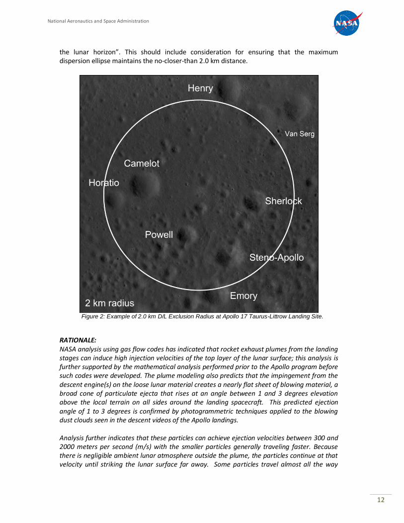
the lunar horizon”. This should include consideration for ensuring that the maximum dispersion ellipse maintains the no-closer-than 2.0 km distance.
Figure 2: Example of 2.0 km D/L Exclusion Radius at Apollo 17 Taurus-Littrow Landing Site.
RATIONALE: NASA analysis using gas flow codes has indicated that rocket exhaust plumes from the landing stages can induce high injection velocities of the top layer of the lunar surface; this analysis is further supported by the mathematical analysis performed prior to the Apollo program before such codes were developed. The plume modeling also predicts that the impingement from the descent engine(s) on the loose lunar material creates a nearly flat sheet of blowing material, a broad cone of particulate ejecta that rises at an angle between 1 and 3 degrees elevation above the local terrain on all sides around the landing spacecraft. This predicted ejection angle of 1 to 3 degrees is confirmed by photogrammetric techniques applied to the blowing dust clouds seen in the descent videos of the Apollo landings. Analysis further indicates that these particles can achieve ejection velocities between 300 and 2000 meters per second (m/s) with the smaller particles generally traveling faster. Because there is negligible ambient lunar atmosphere outside the plume, the particles continue at that velocity until striking the lunar surface far away. Some particles travel almost all the way
National Aeronautics and Space Administration
13
around the moon before impact. The smallest, dust-sized particles achieve near-lunar escape velocity, 2.37 km/s, and even exceed it by a significant margin, sending them into solar orbit, according to some plume simulations. These conclusions are corroborated by the observations of the Apollo crews. Several crew members reported that the blowing material was a flat sheet close to the surface, so that rocks could be seen through the sheet and/or protruding through the top of it. During Apollo 11, Buzz Aldrin reported that while this material was blowing, the lunar horizon became “obscured by a tan haze,” which indicates that the ejected particles were moving fast enough to travel over and beyond the horizon. For the dust-sized particles, the highest velocity achieved is equal to the plume gas velocity, which depends on its combustion temperature and thus chemical composition and, to a lesser degree, the vehicle’s thrust. Thus, a smaller landing vehicle (with comparable propellants) can eject dust-sized particles at comparable velocities, although in lower quantities (mass) per second. Careful review of the landing videos, and comparison to plume modeling, shows that gravel and rocks 1 cm to 10 cm in diameter were also ejected by the plume at speeds between 5 and 50 m/s. Ballistic calculation indicates that these rocks impacted the lunar surface up to 1.5 km from the LM. It is the inertia of these larger particles (in contrast to the low inertia of dust-sized particles) that prevents them from achieving velocities comparable to the plume gas before they run out of the plume into lunar vacuum. Thus, for a smaller lander with less thrust (lower plume gas density), the rocks and gravel will achieve an even smaller fraction of the plume gas velocity and will travel a shorter distance from the landing site. Vehicles larger than the LM could eject rocks a greater distance. Experiments have shown that lunar soil is highly abrasive and effective as a sandblasting medium. The Apollo 12 LM landed 155 m from the Surveyor 3 spacecraft and retrieved material samples from the spacecraft for later analysis. Even though Surveyor was in a crater and below the horizontal plane by 4.3 m and thus “under” the main sheet of material blown from the LM, the Surveyor spacecraft received significant sandblasting and pitting from the Apollo landing. This suggests that collisions between the ejected particles within the main dust sheet scattered them out of that sheet into a much broader but lower-density spray than described above, and it was the scattered particles that impinged on the Surveyor. Comparison with the optical density of the blowing soil indicates that if the Surveyor had been directly impinged by the main sheet, it would have sustained several orders of magnitude greater surface damage, including dust implantation, scouring, pitting, cracking, and microscopic crushing of the surface materials. Thus, the Surveyor’s damage under-represents the degree of damage that could have occurred from an LM-sized vehicle’s plume at that distance. Also, the damage to the Surveyor would have been greater if any of the ejected gravel pieces or rocks had struck it (the odds of such an occurrence have not yet been quantified). Other cases of plume impingement effects have been documented in addition to the Surveyor damage. These include two cases (Apollo 15 and 16) where the launch of the Apollo LM Ascent Stage (AS) blew blankets that had been left on the surface, and the blankets almost impacted and damaged the deployed scientific instruments. O’Brien reported that when the AS lifted off in both Apollo 11 and Apollo 12, the solar cells in the Dust Detector Experiments (DDE) had an immediate change in their received sunlight – sometimes less and sometimes more – attributable to dust being delivered to or knocked off the cells, respectively. In Apollo 11, the DDE was 17 m away from the LM, and in Apollo 12 it was 130 m away. At the latter
National Aeronautics and Space Administration
14
distance, the plume gas would be too rarefied to have much effect, so the observed removal of dust from the DDE was due to the impingement of high-velocity ejecta. At every distance from a spacecraft landing on the Moon, there will be ejected particles that impact at that distance. At large distances the impingement flux becomes small and eventually negligible. However, requiring large distances to protect the Apollo sites could make it impractical for missions to visit them. A landing distance that is specified as a means to protect the sites while still enabling access must be a compromise that reduces the impingement effects without entirely eliminating them. The lunar horizon is roughly 1.8 km from any given point on the lunar surface. By targeting the landing point at 2.0 km from the closest lunar artifact, the main sheet of high-velocity dust-sized particles – which constitutes the largest fraction of the lunar soil – will fly over the top of the artifact site and thus minimize direct impingement. Larger rock or gravel-sized ejecta, which will travel at lower velocities, will impact the lunar surface well short of the horizon, thus also missing the artifact site. The intermediate range of particle sizes (larger, sand-sized particles), which will travel over the horizon but with sufficient downward curvature to strike the artifact site, are a minority fraction of the lunar soil and will have a much lower flux density at impingement from that distance than if the spacecraft were landing closer, thus reducing damage.
A2-4 DISPOSAL OF BRAKING STAGE(s)
RECOMMENDATION: The disposal of all deorbit braking stages should be targeted tangential to the D/L boundary to ensure no overflight of a heritage site and to ensure that the IP is greater than 2.0 km from the heritage site (0.5 km for impact sites).
RATIONALE: Minimize collision potential and the creation of dust clouds within the historic and scientific sites.
A2-5 USE OF NATURAL TERRAIN BARRIERS
RECOMMENDATION: If possible, natural lunar terrain barriers such as hills, crater rims, ridges, or terrain slopes should be used to block the spray of the landing spacecraft. Note that use of natural terrain barriers does not change the D/L boundary recommendations.
RATIONALE: The recommended 2.0 km landing distance reduces but does not entirely eliminate impingement of high-velocity particles. Degradation of the lunar artifacts by ejecta impingement is a cumulative and irreversible effect. It is expected that with increasing access to the lunar surface these sites may be visited frequently, which over time will significantly multiply the effect. Therefore, it is desirable to further reduce impingement to as low as reasonably achievable (ALARA) by taking advantage of natural barriers to block the spray.

National Aeronautics and Space Administration
15
Changes in terrain slope can “ramp” the ejecta into a higher ejection angle so that a larger fraction will fly over the top of the protected site. Natural barriers can block the direct flux of larger particles that curve downward as they cross the horizon, preventing them from reaching the site. It should be noted that the barriers will absorb the momentum of larger impinging particles, but in lunar vacuum, barriers will simply scatter the dust-sized particles without significantly reducing their velocity. It may be possible that using a barrier to scatter the main dust sheet could result in more dust-sized material raining down onto the protected site than if the 2.0 km distance were the only method of mitigation. Dust-sized particles that scatter and then rain down on the site will impinge with no significant reduction in velocity. Further analysis could determine in particular cases of various terrain features whether they reduce or increase the dust impingement at the site, and if they increase the impingement, it could be determined whether that increase is outweighed by the barrier’s blockage and absorption of the larger-sized particles that would have otherwise curved over the horizon and hit the protected site.
A2-6 COLLISION AVOIDANCE WINDOWS
RECOMMENDATION: An analysis specific to the landing vehicle should be performed prior to selecting the landing time and location, in order to determine whether its ejected soil and dust will reach altitudes where it may damage lunar orbiting spacecraft; if so, collision avoidance (COLA) windows should be implemented to prevent landing with the precise timing that could damage those spacecraft.
RATIONALE: From a hypervelocity impact perspective, there may be a concern for damage to sensitive satellite surfaces such as optics (e.g., camera lenses, star trackers, windows, solar cells), and thin materials that should not be perforated in order to function (e.g., light-tight enclosures, thermal insulation). The level of concern would depend on the specific hardware component function, impact sensitivity, and failure criteria. Analysis shows that, depending on the specifics of the lander’s propulsion system, ejected dust may exceed altitudes typical of lunar orbiting spacecraft, and perhaps even exceed lunar escape velocity. Analysis further shows that the density of this ejecta, when it reaches orbital altitudes, is still sufficient to cause numerous impacts on a passing spacecraft. These impacts will be in the hypervelocity regime due to the high relative velocity of the ejecta and the spacecraft. The effects of such impacts are unknown at this time, but might cause significant harm to sensitive features of the spacecraft such as scientific optical instruments. Therefore, to avoid causing damage, an analysis using the particular propulsion system characteristics should be performed to determine the ejecta velocity and the time it will take the ejecta to reach and then pass through the orbital trajectories of each spacecraft in lunar orbit at that time. The particular times that those spacecraft also pass through those intersection points, minus the travel time of the ejecta to get there, determines the landing times that should be avoided. The COLAs will be defined as the windows of time with adequate margin (typically only a few minutes) to avoid landing at that particular location on the moon on that date. NASA has developed software tools to perform this analysis.
National Aeronautics and Space Administration
16
A2-7 LANDER ORIENTATION FOR FINAL APPROACH/LANDING RELATIVE TO THE U.S.HERITAGE SITE (multi-engines descent case)
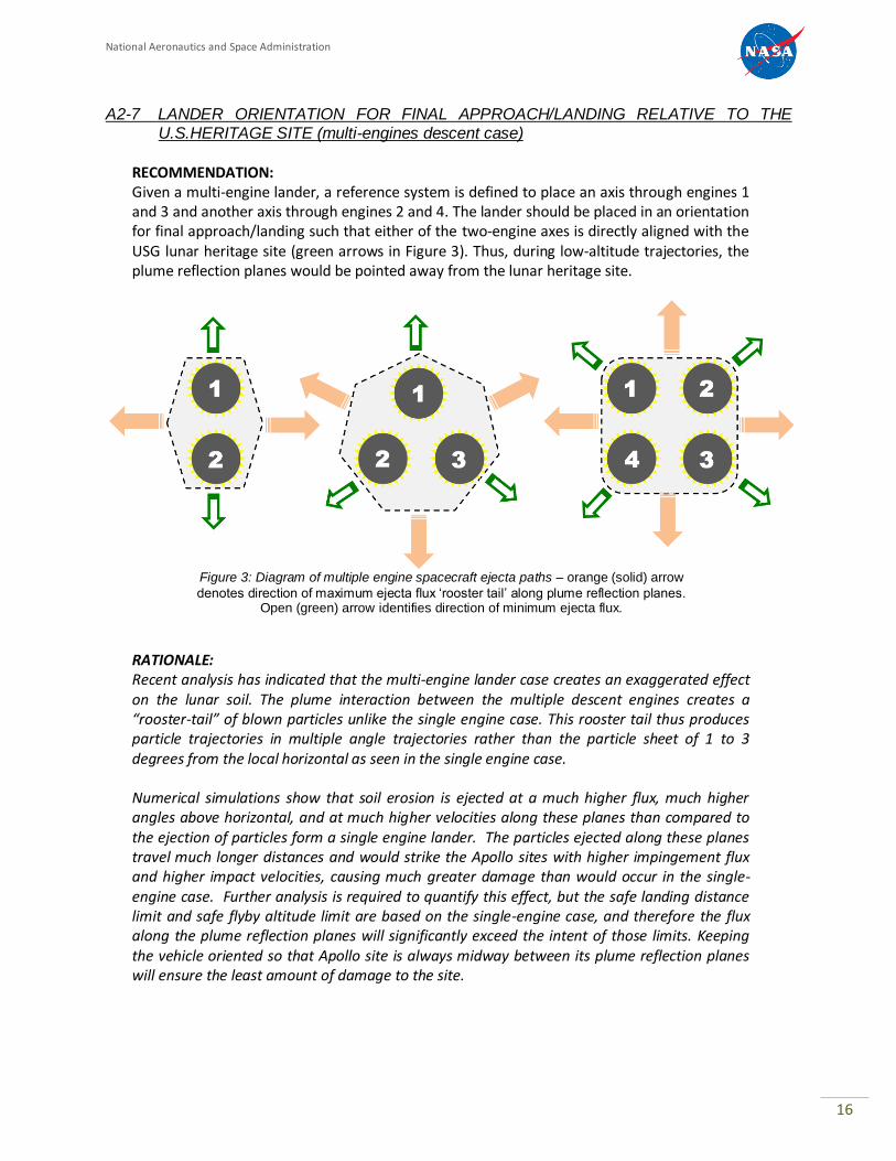
RECOMMENDATION: Given a multi-engine lander, a reference system is defined to place an axis through engines 1 and 3 and another axis through engines 2 and 4. The lander should be placed in an orientation for final approach/landing such that either of the two-engine axes is directly aligned with the USG lunar heritage site (green arrows in Figure 3). Thus, during low-altitude trajectories, the plume reflection planes would be pointed away from the lunar heritage site.
Figure 3: Diagram of multiple engine spacecraft ejecta paths – orange (solid) arrow
denotes direction of maximum ejecta flux ‘rooster tail’ along plume reflection planes. Open (green) arrow identifies direction of minimum ejecta flux.
RATIONALE: Recent analysis has indicated that the multi-engine lander case creates an exaggerated effect on the lunar soil. The plume interaction between the multiple descent engines creates a “rooster-tail” of blown particles unlike the single engine case. This rooster tail thus produces particle trajectories in multiple angle trajectories rather than the particle sheet of 1 to 3 degrees from the local horizontal as seen in the single engine case. Numerical simulations show that soil erosion is ejected at a much higher flux, much higher angles above horizontal, and at much higher velocities along these planes than compared to the ejection of particles form a single engine lander. The particles ejected along these planes travel much longer distances and would strike the Apollo sites with higher impingement flux and higher impact velocities, causing much greater damage than would occur in the single-engine case. Further analysis is required to quantify this effect, but the safe landing distance limit and safe flyby altitude limit are based on the single-engine case, and therefore the flux along the plume reflection planes will significantly exceed the intent of those limits. Keeping the vehicle oriented so that Apollo site is always midway between its plume reflection planes will ensure the least amount of damage to the site.
National Aeronautics and Space Administration
17
SECTION A3 – MOBILITY
ROVERS/HOPPERS/EXCLUSION ZONES
MOBILITY
A3-1 GENERAL OVERVIEW – HISTORICAL PERSPECTIVE PER APOLLO SITE
RECOMMENDATION: While all the Apollo sites represent significant historical/heritage value in material culture, the Apollo 11 and 17 landing sites carry special historical and cultural significance. It is recommended that the sites for Apollo 11 and 17 be treated as unique by prohibiting visits to any part of the site and that all visiting vehicles remain beyond the artifact boundaries (AB) of the entire site.
RATIONALE: Apollo 11 was a pivotal event in human exploration and technology history. Apollo 11 marked the first human flight to the lunar surface; Apollo 17 represented the last within the Apollo Program. Project Apollo in general, and the flight of Apollo 11 in particular, should be viewed as a watershed in human history and humanity. It was the first instance in human history in which emissaries from this planet visited another body in the solar system. It represented the culmination of years of effort, the significant expenditure of life and resources, and the opening of a new age in human history. The site of that first landing requires preservation; only one misstep could forever damage this priceless human treasure.
A3-2 EXCLUSION ZONE – APOLLO 11 & 17 SITES
RECOMMENDATION: It is recommended that the Apollo 11 and 17 sites be protected by ABs, and thus restricted from close inspection by visiting robotic systems. The visiting vehicle mobility exclusion boundary will encompass all artifacts (hardware, footprints, etc.) for these sites.
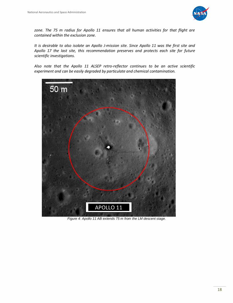
A. For the Apollo 11 site, the exclusion zone extends 75 m from the lunar module descent stage to encompass all hardware and human activity (Figure 4).
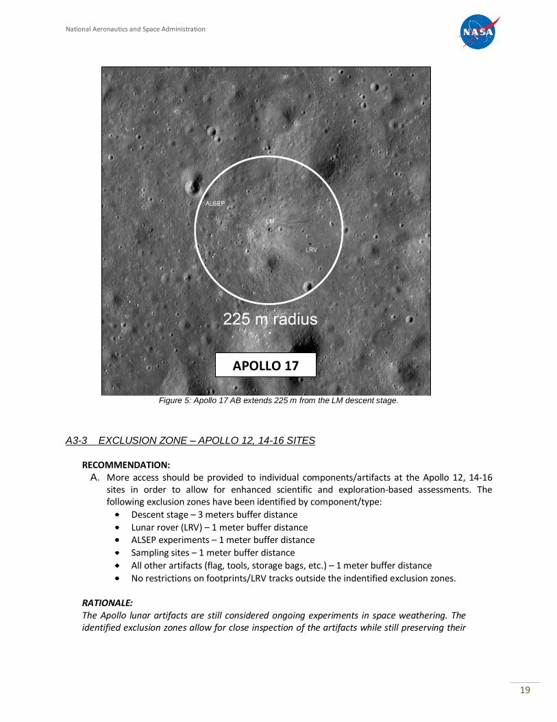
B. For the Apollo 17 site, the exclusion zone extends 225 meters from the lunar module descent stage (Figure 5).
RATIONALE: It is desired to maintain the integrity of the Apollo 11 and Apollo 17 sites. Since the Apollo 11 site is of great historic significance and yet is fairly contained for the hardware and footprints, landers may touch down over the horizon to protect the site from damage, and mobility systems can approach the site as long as they remain outside the larger mobility exclusion
National Aeronautics and Space Administration
18
zone. The 75 m radius for Apollo 11 ensures that all human activities for that flight are contained within the exclusion zone. It is desirable to also isolate an Apollo J-mission site. Since Apollo 11 was the first site and Apollo 17 the last site, this recommendation preserves and protects each site for future scientific investigations. Also note that the Apollo 11 ALSEP retro-reflector continues to be an active scientific experiment and can be easily degraded by particulate and chemical contamination.
APOLLO 11
Figure 4: Apollo 11 AB extends 75 m from the LM descent stage.
National Aeronautics and Space Administration
19
APOLLO 17
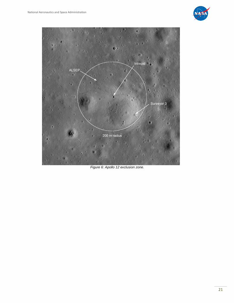
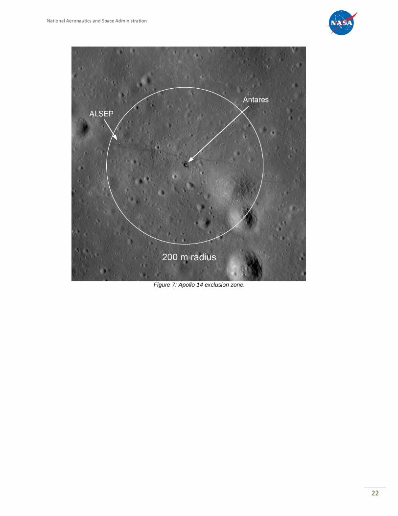
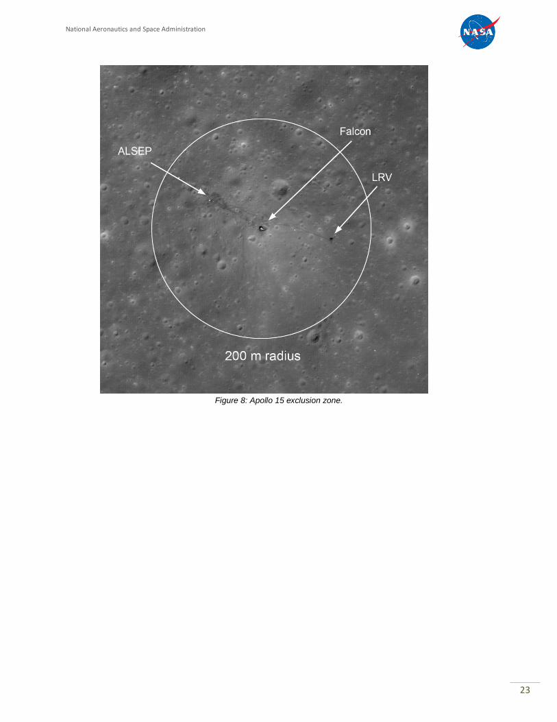
A3-3 EXCLUSION ZONE – APOLLO 12, 14-16 SITES
RECOMMENDATION:
A. More access should be provided to individual components/artifacts at the Apollo 12, 14-16 sites in order to allow for enhanced scientific and exploration-based assessments. The following exclusion zones have been identified by component/type:
Descent stage – 3 meters buffer distance
Lunar rover (LRV) – 1 meter buffer distance ALSEP experiments – 1 meter buffer distance
Sampling sites – 1 meter buffer distance
All other artifacts (flag, tools, storage bags, etc.) – 1 meter buffer distance
No restrictions on footprints/LRV tracks outside the indentified exclusion zones.
RATIONALE: The Apollo lunar artifacts are still considered ongoing experiments in space weathering. The identified exclusion zones allow for close inspection of the artifacts while still preserving their
Figure 5: Apollo 17 AB extends 225 m from the LM descent stage.
National Aeronautics and Space Administration
20
scientific integrity. Also note that the Apollo ALSEP retro-reflectors continue to be active scientific experiments and can be easily degraded by particulate and chemical contamination.
RECOMMENDATION: B. The laser ranging retro-reflectors (LRRRs) should be carefully preserved (See Section A2).
LRRR experiments are found at the Apollo 11, 14, and 15 sites (as well as the Soviet Lunokhod 1 and 2 rover sites). The LRRRs should be treated as special cases with approach mobility being tangential to the site. Once within a 10 m radius zone of the LRRR, mobility can only proceed at speeds that do not propel regolith particles in front of the rover (see Section A3-7) up to the total exclusion zone of 1 m radius around the retroreflector. Direct approach to the LRRR is not recommended.
RATIONALE: While all landing/artificial impact sites have historical value, it should be recognized that the Apollo-era lunar Laser Retro-Reflector Ranging (LRRR) experiment is still ongoing, with laser ranging to passive retroreflectors placed on the lunar surface. The lunar LRRR experiment measures the distance between the Earth and the moon using laser ranging. Since these are active experimental stations, NASA prefers to not risk compromising or contaminating these activities through robotic visits. It should be noted that a physical disturbance would affect 40 years of LRRR data continuity. The stability of the reflectors is critical to a variety of geophysical and relativistic physics problems. It is essential that these sites not be disturbed, however, careful observations of their current state would allow scientists a better idea of what is causing the degradation in the laser return signal, but also help in designing the next generation of LRRRs. Five lunar sites contain LRRRs: Apollo 11, 14, and 15; and two Soviet Lunokhod Rovers deployed by Luna 17 and 21. Accidental deposition of dust on the surfaces of these LRRRs or sandblasting of the retroreflector surfaces would seriously diminish the science return because, as noted by Williams and Dickey (2003)1, many of the science parameters derived from laser-ranging data are very sensitive to time span (i.e., the longer time that data are gathered, the better the science return). However, science can be enabled by close-range (<10 m) of the current LRRRs because over the 40 years that they have been on the lunar surface, degradation of the return signal has been observed (Murphy et al., 2010)2. Close-range observations of the retroreflectors could determine if this is due to increased dust deposition or radiation damage because of the long-term exposure to the space environment (see Section A3). However, the descent and landing of any visiting spacecraft to these sites should not disturb the retroreflector equipment to preserve the existing data integrity.
1 Williams J.G. and Dickey J.O. (2003) Lunar geophysics, geodesy, and dynamics. 13
th International Workshop on Laser Ranging.
2 Murphy T.W. Jr., Adelberger E.G., Battat J.B.R., Hoyle C.D., McMillan R.J., Michelsen E.L., Samad R.L., Stubbs C.W., and
Swanson H.E. (2010) Long-term degradation of optical devices on the Moon. Icarus 208, 31-35.
National Aeronautics and Space Administration
21
Figure 6: Apollo 12 exclusion zone.
National Aeronautics and Space Administration
22
Figure 7: Apollo 14 exclusion zone.
National Aeronautics and Space Administration
23
Figure 8: Apollo 15 exclusion zone.

National Aeronautics and Space Administration
24
Figure 9: Apollo 16 exclusion zone.
National Aeronautics and Space Administration
25
A3-4 EXCLUSION ZONE – SURVEYOR SITE
RECOMMENDATION: A 1 m buffer exclusion zone should be in effect around all Surveyor spacecraft hardware.
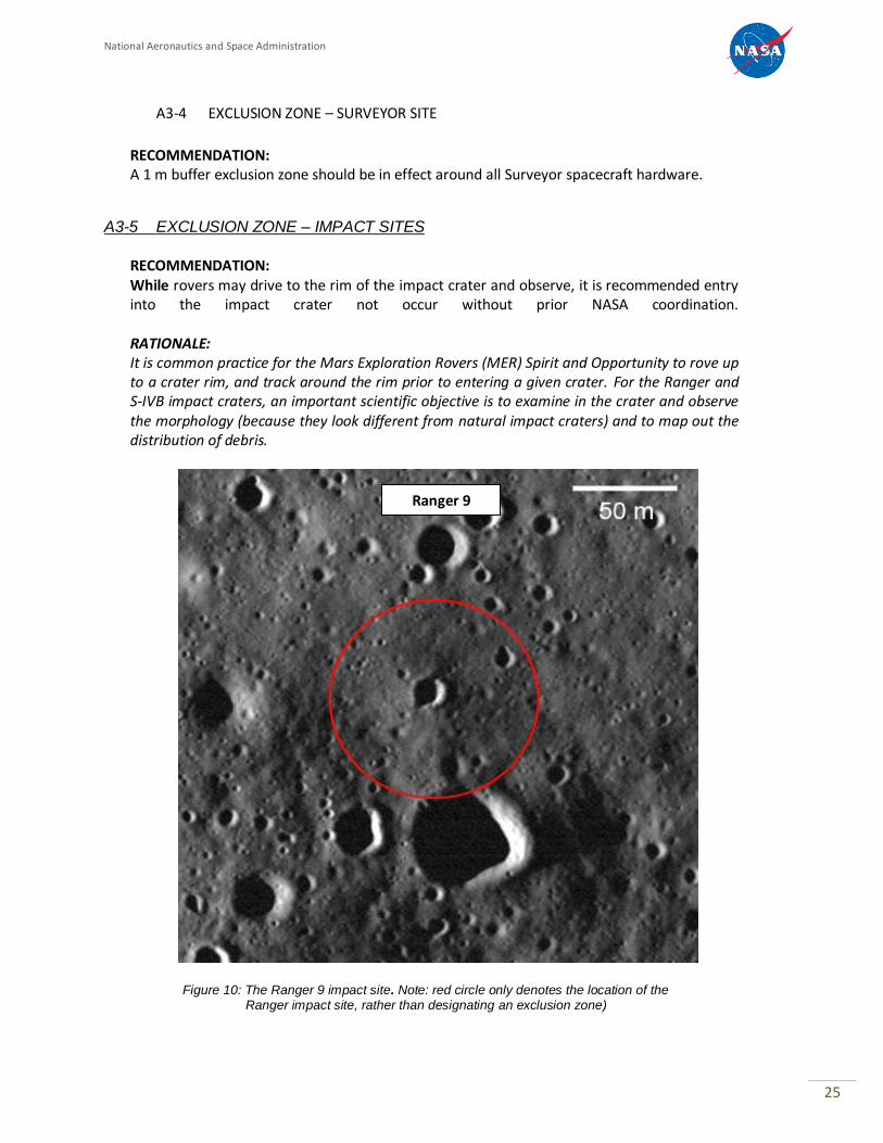
A3-5 EXCLUSION ZONE – IMPACT SITES
RECOMMENDATION: While rovers may drive to the rim of the impact crater and observe, it is recommended entry into the impact crater not occur without prior NASA coordination. RATIONALE: It is common practice for the Mars Exploration Rovers (MER) Spirit and Opportunity to rove up to a crater rim, and track around the rim prior to entering a given crater. For the Ranger and S-IVB impact craters, an important scientific objective is to examine in the crater and observe the morphology (because they look different from natural impact craters) and to map out the distribution of debris.
Ranger 9
Figure 10: The Ranger 9 impact site. Note: red circle only denotes the location of the Ranger impact site, rather than designating an exclusion zone)
National Aeronautics and Space Administration
26
A3-6 EXCLUSION ZONE – ROVERS AT APOLLO SITES
RECOMMENDATION: A. With the exception of the Apollo 11 and 17 sites, rovers should observe the exclusion
zones of individual artifacts at the Apollo 12, 14, 15 and 16 sites.
RATIONALE: In general, slow-moving rovers will not create dust/deposits in and around the site (see section A3-7 below).
RECOMMENDATION: B. For rovers that enter the AB for Apollo site visits, the rover should be removed from
the site boundary prior to lunar sunset and end-of-mission (EOM); and not be left within the site boundary.
RATIONALE: NASA prefers that rovers do not remain parked within the AB at end-of-life. The effects of a severe lunar environment on unattended/uncontrolled space and surface vehicles could lead to containment failures, energetic events or other potential uncontrolled events (e.g., battery venting) that could later contaminate the site. RECOMMENDATION:
C. Tangential approach – rather than allowing a direct-approach to any given artifact, it is recommended that aim points be selected that are tangential to the artifact.
RATIONALE: As recommended in Section A2-1 that all trajectory D/L paths be tangential to the landing sites, it is suggested that a similar philosophy be used in the approach to any heritage artifact. Currently, rovers can take pathways that could aim directly at the artifacts, then stop within the prescribed buffer distance. But this approach doesn’t necessarily protect for “delay-to-stop” cases or failure modes in which the stop command is not properly received or executed. By selecting aim points that are tangential to each artifact, rovers can still gain close access to the target, but minimize contact in the event of “fail-to-stop” cases.
A3-7 LINEAR WHEEL SPEED OF ROBOTIC ROVERS
RECOMMENDATION: No part of the approaching (roving) vehicle should be capable of propelling particles more than half way to an artifact. This sets a limit on speeds of all components of a rover in the neighborhood of artifacts. Specifically, the linear (exterior) wheel speeds of robotic rovers should not exceed the meters/second listed below while traversing within the site in order to avoid casting/throwing dust and particles. Rover designs should consider containment/deflection of casting particles.
National Aeronautics and Space Administration
27
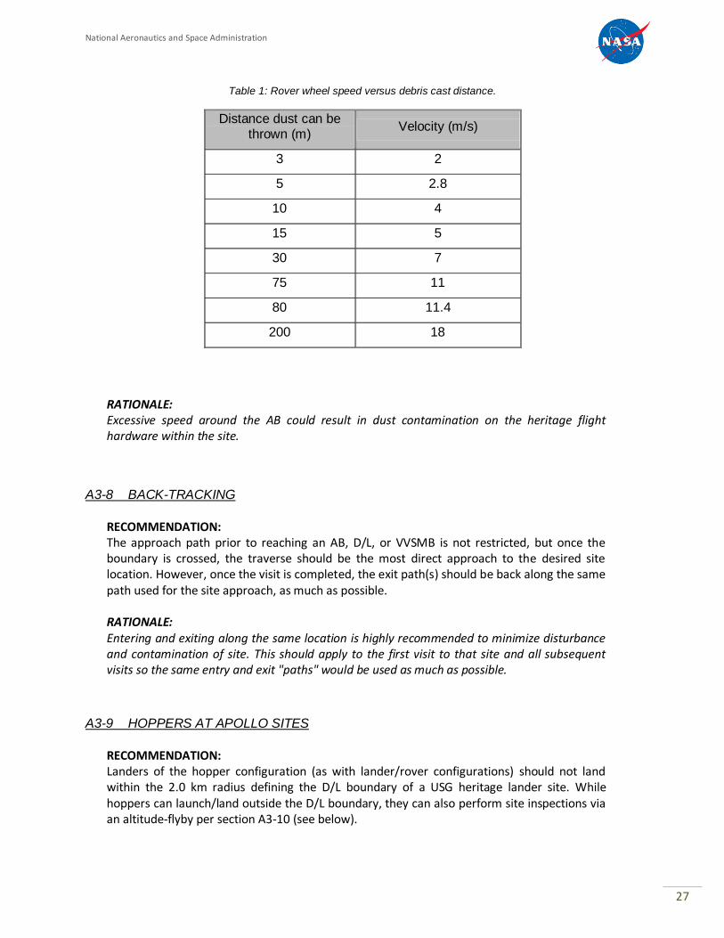
Table 1: Rover wheel speed versus debris cast distance.
Distance dust can be thrown (m)
Velocity (m/s)
3 2
5 2.8
10 4
15 5
30 7
75 11
80 11.4
200 18
RATIONALE: Excessive speed around the AB could result in dust contamination on the heritage flight hardware within the site.
A3-8 BACK-TRACKING
RECOMMENDATION: The approach path prior to reaching an AB, D/L, or VVSMB is not restricted, but once the boundary is crossed, the traverse should be the most direct approach to the desired site location. However, once the visit is completed, the exit path(s) should be back along the same path used for the site approach, as much as possible.
RATIONALE: Entering and exiting along the same location is highly recommended to minimize disturbance and contamination of site. This should apply to the first visit to that site and all subsequent visits so the same entry and exit "paths" would be used as much as possible.
A3-9 HOPPERS AT APOLLO SITES
RECOMMENDATION: Landers of the hopper configuration (as with lander/rover configurations) should not land within the 2.0 km radius defining the D/L boundary of a USG heritage lander site. While hoppers can launch/land outside the D/L boundary, they can also perform site inspections via an altitude-flyby per section A3-10 (see below).
National Aeronautics and Space Administration
28
RATIONALE: Some landers employ a “hopper configuration” for their mobility – reusing descent engines to achieve flight and translation across the lunar terrain. The engines of the hopping configuration create an upwelling of fresh regolith as it ascends from its current location and lands in new regions, which in turn produces additional amounts of dust and debris within the area. Despite the lack of a large, central crater beneath the LMs in the Apollo landings, the amount of ejected soil has been calculated by several methods (optical density, damage to Surveyor, experiments, theory, and shape of the surface beneath the LM) and has been found to be on the order of 1 mt (metric ton) or more. The amount of soil disturbed by a smaller lander is expected to be less, scaling approximately with vehicle thrust, but this can still be a significant quantity for any lunar lander. This dust and resultant high-velocity particles could impart significant damage to a protected site, and damage the site’s historical record (e.g. crew’s footprints and tracks in the case of Apollo landings). Propellant exhaust and ejecta could also affect loose materials like the Modularized Equipment Stowage Assembly (MESA) blanket or other blankets on the Descent Stage and lunar surface.
A3-10 LOW-ALTITUDE FLY-BY OF APOLLO SITES
RECOMMENDATION: It is recommended, for hopper configuration landers, to perform “low-altitude”/ tangential fly-bys of the lunar heritage sites by translating outside of the Apollo hardware's AB, using a minimum of 40 m altitude to the local surface and a tangential distance from the outer hardware AB perimeter consistent with section A4-3 (unburned or residual propellant, see below).
RATIONALE: The low-altitude, tangential fly-by approach allows hopper-configuration landers to provide imagery of lunar heritage sites with minimal risk to the site. Plume impingement: the top layer of the lunar surface is primarily loose particles and dust. During lander translations over the surface, rocket engine exhaust will induce radial ejection of the surface material at high velocities and create dust clouds. These dust/particle streams can result in both contamination and degradation of the protected site. Altitudes of great than 40 m for translations should ensure negligible plume interactions at the surface.
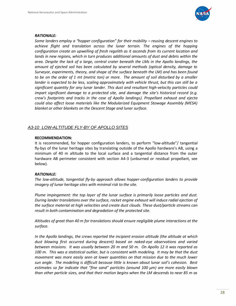
In the Apollo landings, the crews reported the incipient erosion altitude (the altitude at which dust blowing first occurred during descent) based on naked-eye observations and varied between missions. It was usually between 20 m and 50 m. On Apollo 12 it was reported as 100 m. This was a statistical outlier, but is consistent with modeling. It may be that the dust movement was more easily seen at lower quantities on that mission due to the much lower sun angle. The modeling is difficult because little is known about lunar soil’s cohesion. Best estimates so far indicate that “fine sand” particles (around 100 µm) are more easily blown than other particle sizes, and that their motion begins when the LM descends to near 85 m as
National Aeronautics and Space Administration
29
shown in Figure 11. At that altitude, although the fine-sand sized particles do begin to move, they do not experience sufficient lift and will not travel any appreciable distance before falling back to the surface. Also, these particles do not have enough optical density to be seen moving. Only clouds of particles smaller than about 10 µm should be visible to the crew from any appreciable height. The saltating motion of those fine-sand sized particles, however, mechanically disturbs the dust particles (<10 µm), which can overcome the cohesion that had held them to the surface. Once knocked loose, the dust can then be lifted by the plume, accelerated to high velocity, and seen as a dust sheet by the crew. Without the saltating disturbance of fine-sand sized particles, the plume could not directly move the dust-size particles until the LM is below about 25m. The saltating disturbance may explain why the Apollo 12 crew saw dust blowing from such a high altitude. With a spacecraft that has much smaller thrust than the LM, the altitude of initial dust blowing will be lower than these reported values, but it is difficult to predict analytically. Forty meters is chosen as a reasonable estimate until further analysis is performed.
Figure 11: Shear stress generated by a rocket exhaust plume and shear stress levels required to mobilize various sizes of lunar soil particles.
Recently, O’Brien (2009) showed that the plume of the LM ascent stage removed dust from the Dust Detection Experiment at a distance of 130 m during Apollo 12.
National Aeronautics and Space Administration
30
SECTION A4 – CONTAMINATION
A4-1 PHYSICAL CONTACT
RECOMMENDATION: Visiting spacecraft should not physically contact any USG lunar hardware. Exceptions should be pre-coordinated with NASA.
RATIONALE: Lunar dust and potential biological contamination may be transferred from the visiting spacecraft onto the historical assets, degrading the historical site and/or impacting the science value of the site. However, physical contact with USG hardware and/or impact debris may provide additional scientific value, which should be balanced with the potential for damage. Coordination with NASA is recommended to ensure acceptance and understanding of all risks and benefits.
A4-2 DUST
RECOMMENDATION: Visiting spacecraft should always adhere to the altitude and tangential distance constraints given in section A3-10 “Low-altitude Fly-by of Apollo Sites”
RATIONALE: Spacecraft rocket plumes are known to disturb soil on the lunar surface and create sheets/clouds of flying dust. The distances cited in section A3-10 will protect the Apollo site from both dust contamination and degradation from dust abrasion. All mission phases, including low-altitude fly-by, should adhere to the recommended distances.
A4-3 UN-BURNED/RESIDUAL PROPELLANTS
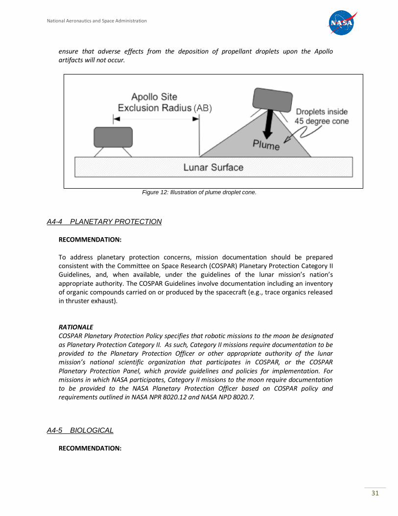
RECOMMENDATION: When within 200 m of the lunar surface, visiting spacecraft should maintain a main engine orientation such that a cone with a half angle of 45 degrees that is centered on the engine axis does not intersect any portion of the exclusion zones defined in Sections A3-2 through A3-6.
RATIONALE: The purpose of this recommendation is to keep the lunar heritage sites from being contaminated with propellant residue that is potentially toxic to humans and/or damaging to Apollo hardware (e.g., corrosive). Studies have shown that droplets large enough to be of consequence (larger than one micron in diameter) of unburned/residual propellant from spacecraft rocket motors are confined to within 45 degrees of the engine thrust axis when the rocket is operated in a vacuum environment. Therefore, adherence to this constraint will
National Aeronautics and Space Administration
31
ensure that adverse effects from the deposition of propellant droplets upon the Apollo artifacts will not occur.
Figure 12: Illustration of plume droplet cone.
A4-4 PLANETARY PROTECTION
RECOMMENDATION: To address planetary protection concerns, mission documentation should be prepared consistent with the Committee on Space Research (COSPAR) Planetary Protection Category II Guidelines, and, when available, under the guidelines of the lunar mission’s nation’s appropriate authority. The COSPAR Guidelines involve documentation including an inventory of organic compounds carried on or produced by the spacecraft (e.g., trace organics released in thruster exhaust).
RATIONALE COSPAR Planetary Protection Policy specifies that robotic missions to the moon be designated as Planetary Protection Category II. As such, Category II missions require documentation to be provided to the Planetary Protection Officer or other appropriate authority of the lunar mission’s national scientific organization that participates in COSPAR, or the COSPAR Planetary Protection Panel, which provide guidelines and policies for implementation. For missions in which NASA participates, Category II missions to the moon require documentation to be provided to the NASA Planetary Protection Officer based on COSPAR policy and requirements outlined in NASA NPR 8020.12 and NASA NPD 8020.7.
A4-5 BIOLOGICAL
RECOMMENDATION:
National Aeronautics and Space Administration
32
To address concerns about microbial and biological contamination at historic and scientific sites, visiting spacecraft should follow all recommended exclusion zones, boundaries and restrictions outlined in these recommendations.
RATIONALE Remnant detectable microbial levels and biological contamination, if any, at historical lunar mission sites represent valuable, irreplaceable data of scientific interest. Concerns about microbial and biological contamination at historical sites will be sufficiently addressed by following all recommended exclusion zones, boundaries and restrictions outlined in these recommendations.
National Aeronautics and Space Administration
33
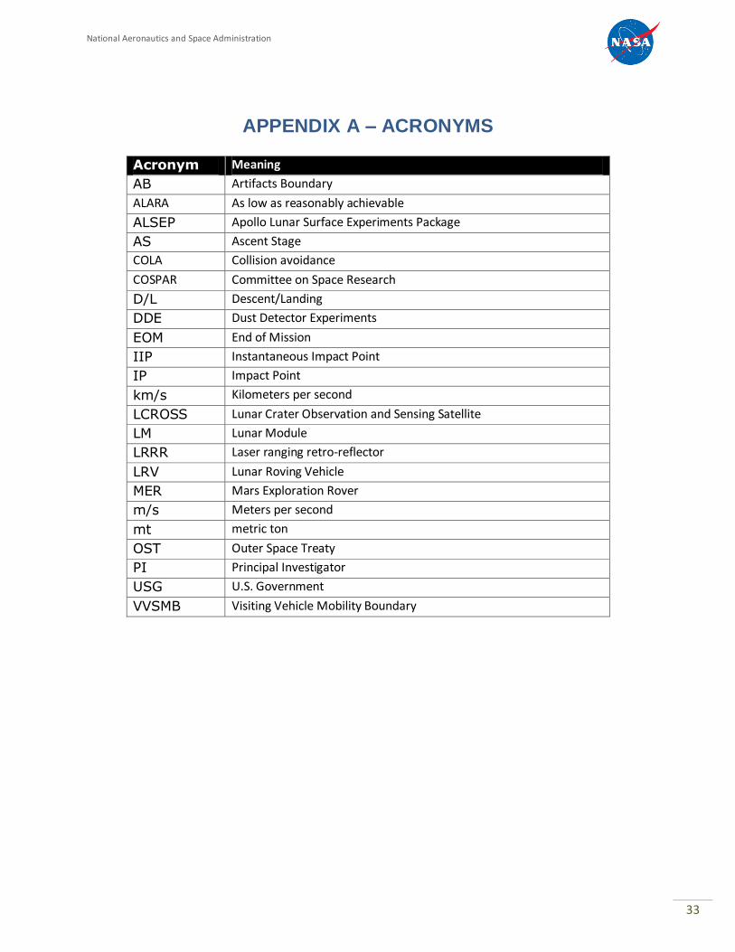
APPENDIX A – ACRONYMS
Acronym Meaning
AB Artifacts Boundary
ALARA As low as reasonably achievable
ALSEP Apollo Lunar Surface Experiments Package
AS Ascent Stage
COLA Collision avoidance
COSPAR Committee on Space Research
D/L Descent/Landing
DDE Dust Detector Experiments
EOM End of Mission
IIP Instantaneous Impact Point
IP Impact Point
km/s Kilometers per second
LCROSS Lunar Crater Observation and Sensing Satellite
LM Lunar Module
LRRR Laser ranging retro-reflector
LRV Lunar Roving Vehicle
MER Mars Exploration Rover
m/s Meters per second
mt metric ton
OST Outer Space Treaty
PI Principal Investigator
USG U.S. Government
VVSMB Visiting Vehicle Mobility Boundary
National Aeronautics and Space Administration
34
APPENDIX B – NASA Engineering / Safety Center (NESC)
Evaluation of Apollo Artifacts as Witness Plates
Future visits to the Moon’s surface, such as those anticipated by participants in the Google Lunar X-Prize (GLXP) competition, offer a unique opportunity to study the effects of exposure to the lunar environment on materials and articles left behind by previous lunar missions. Very little data exist that describe what effect temperature extremes, lunar dust, micrometeoroids, solar radiation, etc. have on man-made material, and no data exist for time frames approaching the 4 decades elapsed since the Apollo missions. Some of the hardware on the Moon was designed to remain operable and transmit telemetered scientific data back to the Earth, but much of what is there was meant to be used during the Apollo mission time frame and then abandoned with no expectation of further survivability. How these artifacts and their constituent materials have survived and been altered while on the lunar surface is of great interest to engineers and scientists. The Apollo artifacts are, in essence, witness plates to 38+ years on the Moon.
The NASA Engineering and Safety Center (NESC) was asked to consider these possible effects of the lunar environment on man-made artifacts and suggest which artifacts would be the most enticing targets for imaging or investigation by future visiting vehicles. The NESC team used Apollo 15 as a representative landing site. The Apollo 15 crew left 189 individually cataloged items on the lunar surface, including the descent stage of the Lunar Module, the Lunar Roving Vehicle (LRV), the Apollo Lunar Surface Experiments Package (ALSEP), and a wide variety of miscellaneous items that were offloaded by the astronauts to save weight prior to departure. The locations of many of these items are well documented, and numerous photographs are available to establish their appearance and condition at the time they were left behind. The NESC team formed for this activity consisted of several NASA Technical Fellows and members of technical discipline teams (TDT) with expertise in thermal control, materials, mechanical systems, lunar environment, nondestructive evaluation, and environmental control and life support (see Table B1).
Table B1: NESC Team Members
Neil Dennehy Guidance, Navigation and Control Technical Fellow
Jared Dervan NESC Resident Engineer Michael Dube Mechanical Systems TDT
William Prosser Nondestructive Evaluation Technical Fellow
Steven Rickman Passive Thermal Technical Fellow
Henry Rotter Life Support and Active Thermal Technical Fellow (Apollo Veteran)
Donald Shockey Materials TDT Michael Sims Robotics TDT/Center for Collaboration Science and Applications
Michael Squire NESC Principal Engineers Office
Input was also received from members of the original Bendix Corporation team that designed and built the ALSEP instruments. Specific thanks go to Mr. Lynn Lewis, who provided much of the information in Table B2 and additional observations in this appendix.
National Aeronautics and Space Administration
35
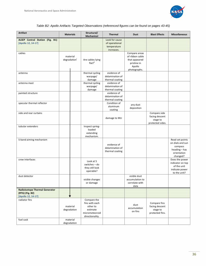
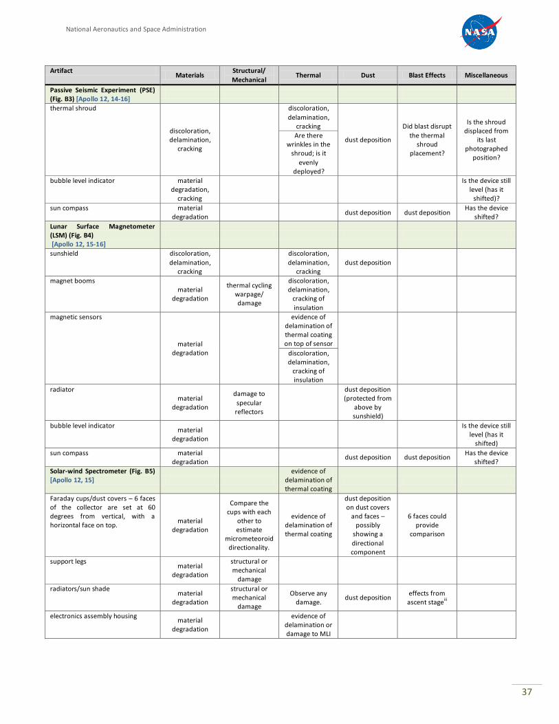
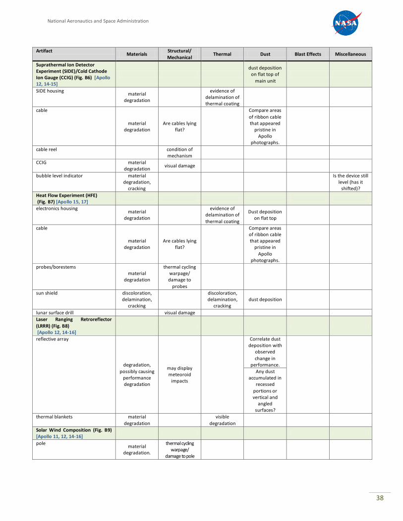
The task for the NESC team was to determine which artifacts were accessible and evaluate what benefits might be realized by taking high definition images of each one. Accordingly, the ground rules set for this NESC activity were to assume that the only scientific equipment available will be high definition cameras, and no physical contact with the artifacts is allowed. The NESC team’s conclusions are presented in Table B2 where they are categorized as follows:
Materials: One of the primary objectives in looking at the artifacts is to gauge the effect of the lunar environment on different materials. Conditions on the lunar surface vary in temperature from +250° F to -300° F and include exposure to ultraviolet and other forms of radiation, so material surfaces after 40 years of exposure to this environment could be discolored, faded, dulled, flaked, rumpled, pitted, mud-cracked, scratched, and/or covered with dust. Structural/mechanical: The temperature extremes may have caused some artifacts to exhibit thermal effects, and the 500-plus day-night thermal cycles may have caused thermal fatigue damage or deformation due to dissimilar metals being in contact with each other. In addition, micrometeoroid impacts may have produced craters whose number, size, and appearance may be useful in updating current models. Radially symmetric objects with several impacts may be able to give some rough directional information as well. Thermal: Most of the Apollo hardware received some form of thermal protection. This included multilayer insulation (MLI), radiators/reflectors, and/or thermal paint. There is interest is seeing how these different systems may have degraded. Dust: Much has been documented on the characteristics of lunar dust and the deleterious effect it has on equipment. There is also interest in dust transportation and deposition from human activities and natural processes. Flat surfaces (especially horizontal) and artifacts that appear pristine in Apollo photographs would be optimum targets to look for dust deposition. Blast Effects: Observations of how blast effects from nearby rocket engines vary as a function of distance may be possible by looking at some affected artifacts. Miscellaneous: Captured here are observations not easily grouped in any of the above categories.
National Aeronautics and Space Administration
36
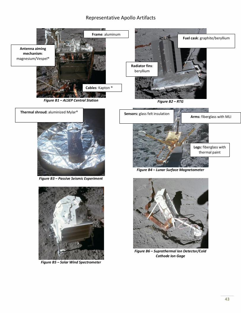
Table B2: Apollo Artifacts Targeted Observations (referenced figures can be found on pages 43-45)
Artifact Materials
Structural/ Mechanical
Thermal Dust Blast Effects Miscellaneous
ALSEP Central Station (Fig. B1) [Apollo 12, 14-17]
Look for cause of operational
temperature increases.
cables material
degradationi Are cables lying
flat?ii
Compare areas of ribbon cable that appeared
pristine in Apollo
photographs.
antenna
thermal cycling
warpage/ damage
evidence of
delamination of thermal coating
antenna mast
thermal cycling warpage/ damage
evidence of delamination of thermal coating
painted structure
evidence of delamination of thermal coating
specular thermal reflector
Condition of aluminum
coating
any dust deposition
side and rear curtains
damage to MLI
Compare side
facing descent stage to
protected sides.
tubular extenders
Inspect spring-loaded
extending mechanism.
S-band aiming mechanism
evidence of
delamination of thermal coating
Read set points on dials and sun
compass heading – has
orientation changed?
crew interfaces
Look at 5 switches – do they still look
operable?
Does the power
indicator on top of the unit
indicate power to the unit?
dust detector
visible changes
or damage
visible dust
accumulation to correlate with
data
Radioisotope Thermal Generator (RTG) (Fig. B2) [Apollo 12, 14-17]
radiator fins
material degradation
Compare the fins with each
other to estimate
micrometeoroid
directionality.
dust
accumulation on fins
Compare fins facing descent
stage to protected fins.
fuel cask material degradation
National Aeronautics and Space Administration
37
Artifact Materials
Structural/
Mechanical Thermal Dust Blast Effects Miscellaneous
Passive Seismic Experiment (PSE) (Fig. B3) [Apollo 12, 14-16]
thermal shroud
discoloration, delamination,
cracking
discoloration,
delamination, cracking
dust deposition
Did blast disrupt
the thermal shroud
placement?
Is the shroud displaced from
its last photographed
position?
Are there wrinkles in the
shroud; is it
evenly deployed?
bubble level indicator material degradation,
cracking
Is the device still level (has it
shifted)?
sun compass material degradation
dust deposition dust deposition Has the device
shifted?
Lunar Surface Magnetometer (LSM) (Fig. B4) [Apollo 12, 15-16]
sunshield discoloration,
delamination, cracking
discoloration,
delamination, cracking
dust deposition
magnet booms material
degradation
thermal cycling warpage/ damage
discoloration, delamination,
cracking of
insulation
magnetic sensors
material degradation
evidence of delamination of thermal coating on top of sensor
discoloration, delamination,
cracking of insulation
radiator material
degradation
damage to
specular reflectors
dust deposition (protected from
above by sunshield)
bubble level indicator material
degradation
Is the device still level (has it
shifted)
sun compass material degradation
dust deposition dust deposition Has the device
shifted?
Solar-wind Spectrometer (Fig. B5) [Apollo 12, 15]
evidence of delamination of thermal coating
Faraday cups/dust covers – 6 faces of the collector are set at 60 degrees from vertical, with a horizontal face on top.
material degradation
Compare the cups with each
other to estimate
micrometeoroid directionality.
evidence of delamination of thermal coating
dust deposition on dust covers
and faces – possibly
showing a
directional component
6 faces could provide
comparison
support legs material
degradation
structural or mechanical
damage
radiators/sun shade material
degradation
structural or mechanical
damage
Observe any damage.
dust deposition effects from
ascent stageiii
electronics assembly housing material
degradation
evidence of delamination or damage to MLI
National Aeronautics and Space Administration
38
Artifact Materials
Structural/
Mechanical Thermal Dust Blast Effects Miscellaneous
Suprathermal Ion Detector Experiment (SIDE)/Cold Cathode Ion Gauge (CCIG) (Fig. B6) [Apollo 12, 14-15]
dust deposition
on flat top of
main unit
SIDE housing material
degradation
evidence of delamination of thermal coating
cable
material degradation
Are cables lying flat?
Compare areas
of ribbon cable that appeared
pristine in Apollo
photographs.
cable reel
condition of mechanism
CCIG material degradation
visual damage
bubble level indicator material degradation,
cracking
Is the device still level (has it
shifted)?
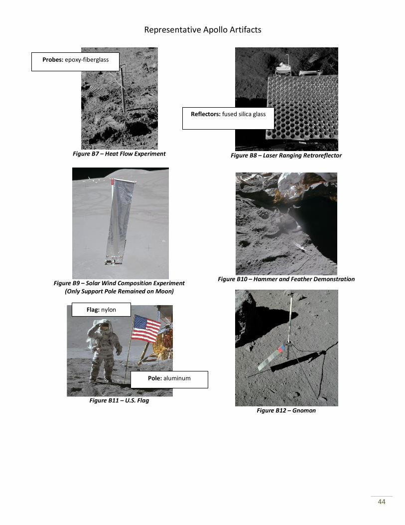
Heat Flow Experiment (HFE) (Fig. B7) [Apollo 15, 17]
electronics housing material
degradation
evidence of delamination of
thermal coating
Dust deposition on flat top
cable
material degradation
Are cables lying flat?
Compare areas of ribbon cable that appeared
pristine in
Apollo photographs.
probes/borestems material
degradation
thermal cycling warpage/
damage to
probes
sun shield discoloration, delamination,
cracking
discoloration, delamination,
cracking dust deposition
lunar surface drill visual damage
Laser Ranging Retroreflector
(LRRR) (Fig. B8) [Apollo 12, 14-16]
reflective array
degradation,
possibly causing performance degradation
may display meteoroid
impacts
Correlate dust deposition with
observed
change in performance.
Any dust
accumulated in recessed
portions or vertical and
angled surfaces?
thermal blankets material
degradation
visible
degradation
Solar Wind Composition (Fig. B9) [Apollo 11, 12, 14-16]
pole material
degradation.
thermal cycling warpage/
damage to pole
National Aeronautics and Space Administration
39
Artifact Materials
Structural/
Mechanical Thermal Dust Blast Effects Miscellaneous
Hammer and Feather (gravity demonstration experiment) (Fig. B10) [Apollo 15]
effect of lunar environment on
biological material (feather)
Did the blast
move the feather?
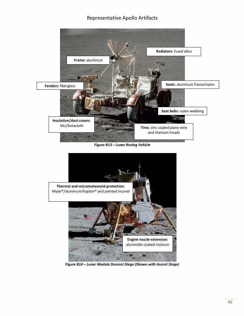
Lunar Rover Vehicle (LRV) (Fig. B13) [Apollo 15-17]
Look at structural joints for evidence of thermal fatigue
or cracking.
seats
degradation of nylon strips
Higher elevation of the seats may
allow comparison
with lower level artifacts;
depending on orientation relative to
descent stage, the seats may have received
some blast
protection.
seat belts degradation of nylon
structure
areas where dissimilar metals are
joined to look for thermal
cycling effects
evidence of delamination of
thermal coating
fenders degradation/ discoloring of
fiberglass
radiators
if dust cover removed –
discoloration, visible
degradation, look for dust accumulation
high-gain antenna
thermal cycling warpage/
damage to mast
low-gain antenna
thermal cycling warpage/
damage to mast
video camera
visible
degradation of the optics
crew interfaces
degradation in switches and
gauges
Are the gauges obscured with
dust?
Are the gauges obscured with
dust or blasted?
Try to read values on gauges.
National Aeronautics and Space Administration
40
Artifact Materials
Structural/
Mechanical Thermal Dust Blast Effects Miscellaneous
Lunar Module (Descent Stage) (Fig. B14)
dust deposition on the top
surface
blast damage on top of LM
engine nozzle extension degradation
thermal/MMOD shield
damage from ascent plume
heating
See if insulation integrity was
compromised by ascent stage
blast.
footpads discoloration
RTG fuel cask thermal shield
visible evidence of radiation
leakage during flight
US flag (Fig. B11) degradation of
nylon flag
thermal cycling warpage/
damage to pole
clothing
discoloration – compare to
ground samples/ pictures
food/waste
visible effect of lunar
environment on biological material
gnomon (Fig. B12)
How have the colors changed
on the color standard?
Lunar Surface
changes in tire/foot prints
such as
smoothing, collapsing into
the track size and shape of ascent stage
excavations
new meteorite
craters or linear features
recorded by the PSE
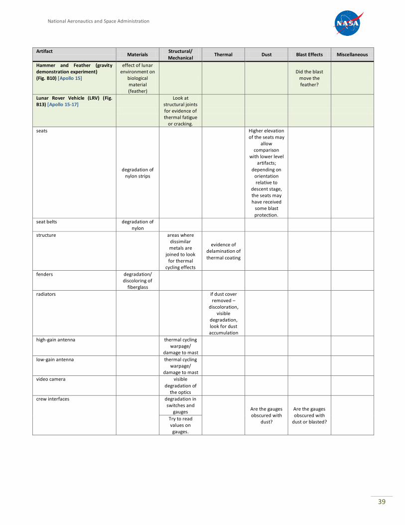
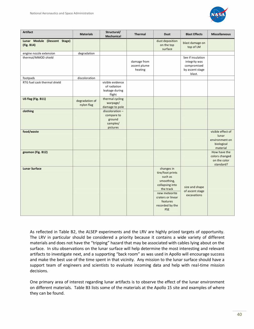
As reflected in Table B2, the ALSEP experiments and the LRV are highly prized targets of opportunity. The LRV in particular should be considered a priority because it contains a wide variety of different materials and does not have the “tripping” hazard that may be associated with cables lying about on the surface. In situ observations on the lunar surface will help determine the most interesting and relevant artifacts to investigate next, and a supporting “back room” as was used in Apollo will encourage success and make the best use of the time spent in that vicinity. Any mission to the lunar surface should have a support team of engineers and scientists to evaluate incoming data and help with real-time mission decisions. One primary area of interest regarding lunar artifacts is to observe the effect of the lunar environment on different materials. Table B3 lists some of the materials at the Apollo 15 site and examples of where they can be found.

National Aeronautics and Space Administration
41
Table B3: Materials on Lunar Surface
Aluminum Various structural components
Aluminized Mylar® Insulation and reflectors
Graphite/beryllium RTG fuel cask
Fiberglass LSM support arms/LRV fenders
Fused silica glass LRRR mirrors, LRV radiators
Nylon LRV seats and seat belts, flag
Zinc LRV tires
Titanium LRV tires
Stainless steel Plaque on LM, ALSEP fasteners/clips/latches
Beryllium RTG radiators
S-13 G and Z-93 white paint Solar reflectors
Gold Infrared reflectors
Aluminized Kapton® Insulation
Aluminized Teflon® ALSEP shroud material
Magnesium LRV batteries
Chromel® R metal fabric Boots, gloves
Niobium Descent stage engine nozzle extension
In addition, points of reference and comparison are important in evaluating levels of damage or change to the lunar hardware. Any standards or baselines in the form of Earth-based existing materials, spares, or test data that can be used as comparisons to lunar observations would provide enhanced scientific and material value.
National Aeronautics and Space Administration
42
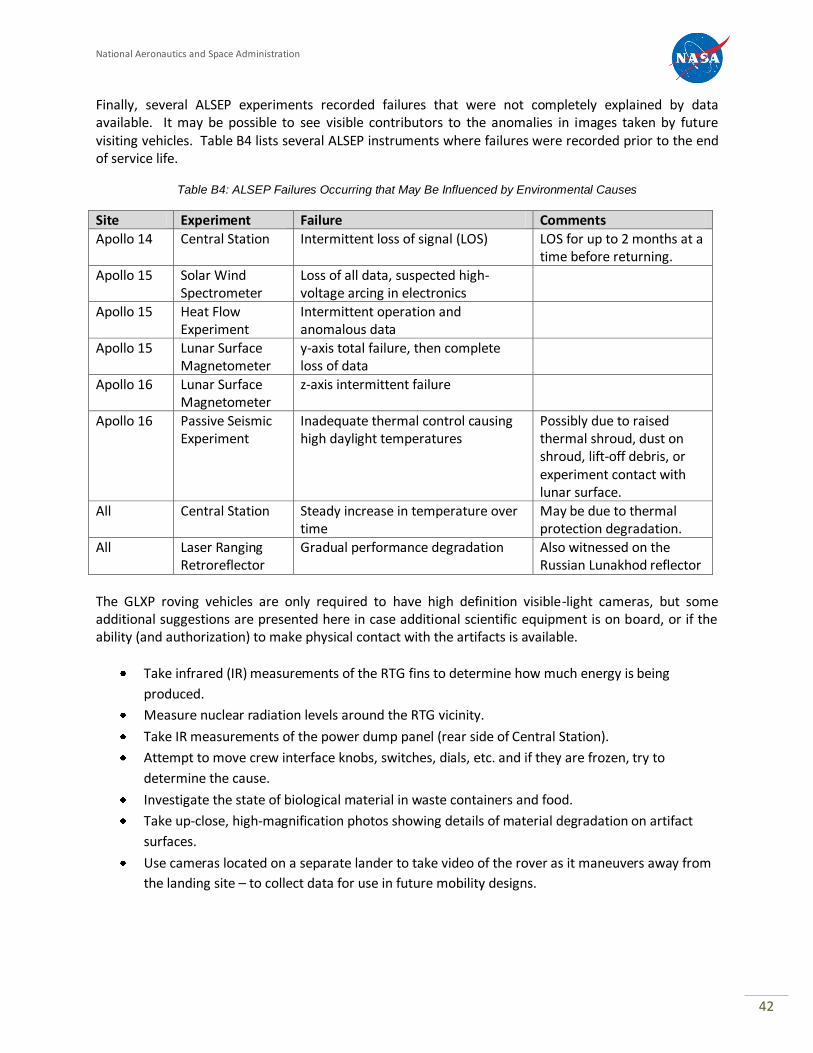
Finally, several ALSEP experiments recorded failures that were not completely explained by data available. It may be possible to see visible contributors to the anomalies in images taken by future visiting vehicles. Table B4 lists several ALSEP instruments where failures were recorded prior to the end of service life.
Table B4: ALSEP Failures Occurring that May Be Influenced by Environmental Causes
Site Experiment Failure Comments
Apollo 14 Central Station Intermittent loss of signal (LOS) LOS for up to 2 months at a time before returning.
Apollo 15 Solar Wind Spectrometer
Loss of all data, suspected high-voltage arcing in electronics
Apollo 15 Heat Flow Experiment
Intermittent operation and anomalous data
Apollo 15 Lunar Surface Magnetometer
y-axis total failure, then complete loss of data
Apollo 16 Lunar Surface Magnetometer
z-axis intermittent failure
Apollo 16 Passive Seismic Experiment
Inadequate thermal control causing high daylight temperatures
Possibly due to raised thermal shroud, dust on shroud, lift-off debris, or experiment contact with lunar surface.
All Central Station Steady increase in temperature over time
May be due to thermal protection degradation.
All Laser Ranging Retroreflector
Gradual performance degradation Also witnessed on the Russian Lunakhod reflector
The GLXP roving vehicles are only required to have high definition visible-light cameras, but some additional suggestions are presented here in case additional scientific equipment is on board, or if the ability (and authorization) to make physical contact with the artifacts is available.
Take infrared (IR) measurements of the RTG fins to determine how much energy is being
produced.
Measure nuclear radiation levels around the RTG vicinity.
Take IR measurements of the power dump panel (rear side of Central Station).
Attempt to move crew interface knobs, switches, dials, etc. and if they are frozen, try to
determine the cause.
Investigate the state of biological material in waste containers and food.
Take up-close, high-magnification photos showing details of material degradation on artifact
surfaces.
Use cameras located on a separate lander to take video of the rover as it maneuvers away from
the landing site – to collect data for use in future mobility designs.
Representative Apollo Artifacts
43
Figure B1 – ALSEP Central Station Figure B2 – RTG
Figure B3 – Passive Seismic Experiment
Figure B4 – Lunar Surface Magnetometer
Figure B5 – Solar Wind Spectrometer
Antenna aiming mechanism:
magnesium/Vespel®
Figure B6 – Suprathermal Ion Detector/Cold
Cathode Ion Gage
Frame: aluminum
Cables: Kapton ®
Radiator fins:
beryllium
Fuel cask: graphite/beryllium
Thermal shroud: aluminized Mylar® Arms: fiberglass with MLI
Sensors: glass felt insulation
Legs: fiberglass with
thermal paint
Representative Apollo Artifacts
44
Figure B7 – Heat Flow Experiment
Figure B8 – Laser Ranging Retroreflector
Figure B9 – Solar Wind Composition Experiment
(Only Support Pole Remained on Moon)
Figure B10 – Hammer and Feather Demonstration
Figure B11 – U.S. Flag
Probes: epoxy-fiberglass
Pole: aluminum
Flag: nylon
Reflectors: fused silica glass
Figure B12 – Gnomon
Representative Apollo Artifacts
45
Figure B13 – Lunar Roving Vehicle
Fenders: fiberglass
Insulation/dust covers:
MLI/betacloth
Radiators: fused silica mirrors
Tires: zinc coated piano wire and titanium treads
Seat belts: nylon webbing
Frame: aluminum
Seats: aluminum frame/nylon strips
Thermal and micrometeoroid protection:
Mylar®/aluminum/Kapton® and painted inconel
Engine nozzle extension:
aluminide-coated niobium
Figure B14 – Lunar Module Descent Stage (Shown with Ascent Stage)

Representative Apollo Artifacts
46
The following references were used to provide information for this appendix.
1. Apollo Artifacts Left on the Moon, list provide by Dr. Roger D. Launius, National Air and Space
Museum, Smithsonian Institution, 1985-86.
2. J.R. Bates, W.W. Lauderdale, H. Kernaghan, ALSEP Termination Report, NASA Reference
Publication 1036, April 1979.
3. L.R. Lewis, “ALSEP: The Scientific Voice of the Moon,” Bendix Technical Journal,
Summer/Autumn 1971.
4. J.L. McNaughton, “Some Aspects of ALSEP Structural/Thermal Design,” Bendix Technical
Journal, Summer/Autumn 1971.
5. R.S. Harris, Jr., Apollo Experience Report – Thermal Design of Apollo Lunar Surface
Experiments Package, NASA Technical Note D-6738, March 1972.
6. W.W. Lauderdale, W.F. Eichelman, Apollo Scientific Experiments Data Handbook, NASA TM X-
58131, August 1974.
7. T. A. Sullivan, Catalog of Apollo Experiment Operations, NASA Reference Publication 1317,
January 1994.
8. NASA Apollo 15 Press Kit, Release Number 71-119K, Thursday A.M. July 15, 1971.
9. NASA Apollo 11 Press Kit, Release Number 69-83K, July 6, 1969.
10. Apollo 15 Preliminary Science Report, NASA SP-289, 1972.
11. Apollo 12 Preliminary Science Report, NASA SP-235, 1970.
12. Apollo 16 Preliminary Science Report, NASA SP-315, 1972.
13. Lunar Roving Vehicle Operations Handbook, LS006-002-2H, Boeing Company – LRV Systems
Engineering, April 19, 1971.
14. Lunar Module LM 10 through LM 14 Vehicle Familiarization Manual, LMA790-2, Grumman
Aerospace Corporation, November 1, 1969.
15. T.W. Murphy, et al., Long-term Degradation of Optical Devices on the Moon, March 3, 2010.
16. Lunar and Planetary Institute, http://www.lpi.usra.edu/
17. Project Apollo Archive Apollo Image Gallery, http://apolloarchive.com/apollo_gallery.html
18. National Space Science Data Center, http://nssdc.gsrc.nasa.gov/
Representative Apollo Artifacts
47
APPENDIX C – NASA LUNAR SCIENCE ASSESSMENT OF
APOLLO SITES AS WITNESS PLATES
I. Introduction
Soft landings on the Moon, both robotic and crewed (Apollo) resulted in scientific investigations of the surrounding region. For Surveyor, the investigation was largely photographic although some manipulation of the soil near the spacecraft was photographed in order to evaluate the geotechnical characteristics of the surface material. Some of the landed Surveyors had an alpha particle backscattering experiment and a magnet to learn about the mineralogical properties of the regolith. The Soviet Lunokhod rover successfully ranged over significant distances before failing. Of course, the Apollo astronauts explored and sampled areas around the landed Lunar Module, extensive areas in the case of the ‘J’ Missions (A15, A16, and A17). In this section we discuss special locations, usually small in area, where preservation of the extant surface environment has value for understanding more completely the scientific findings from that special location. We also discuss photographs that could add to our understanding of scientific and technological issues related to the lunar surface. (We assume herein that no measurements other than high-resolution images can be available.) More information on any Apollo experiments discussed below can be found at http://www.hq.nasa.gov/alsj/RP-1994-1317.pdf.
II. Science hardware
A. Lunar Laser Ranging Retroreflectors (LRRR) [A11, A14, A15, Lunokhods 1 & 2]
The Lunar Laser Ranging Retroreflectors were emplaced at A11, A14, and A15. The Soviet Lunokhod rovers also carried retroreflector arrays. All of these arrays are currently being used for research into lunar motion, dynamics, and internal structure. The corner cube reflectors comprising each array MUST not be degraded by dust deposition or other contamination from visits. We cannot emphasize enough the importance of NOT doing anything to degrade the performance of the arrays. In general, this concern leads to establishment of a buffer distance for any active device approaching the arrays. On the other hand, the current state of the reflector surfaces is of great interest to determine, in particular, whether fine-grained lunar surface material coats the surfaces. The strength of the return signal was not measured on Earth when the surfaces were known to be pristine. However, data that does exist suggests some loss of performance has occurred for reasons that are only be speculative. A clear, relatively high-resolution image of an array surface would be very valuable. A picture from the farthest distance compatible with zoom capability of the camera is greatly preferred.
Representative Apollo Artifacts
48
B. Heat Flow Probes [A15, A17]
One of the most important geophysical experiments left on the Moon by the Apollo astronauts (A15, A16, and A17) is the Heat Flow Experiment (HFE). A probe consisting of thermocouples and other instrumentation was inserted into a bore hole drilled by the astronauts. The A16 instrument was inadvertently damaged during deployment and never operated. At A15, one probe could not be installed properly; and the other probe could not be inserted to its fully intended depth, resulting in some thermocouples lying on the upper surface. Post-mission data analysis from telemetry of temperature readings showed that accurate modeling of the local and regional environments was necessary to properly interpret the data. The configuration of the probes, including the string of thermocouples lying on the surface at A15, should not be disturbed. However, photographic documentation of the configuration would be useful.
C. Soviet Luna missions
Of note and for completeness, the Soviet Union successfully landed robotic spacecraft on the lunar surface 7 times. Lunas 9 and 13 returned photographs of their landing sites along with some measurements of the lunar surface environment. Lunas 16, 20, and 24 returned lunar surface samples to Earth. The geologic setting of the samples is not well known, although the Lunar Reconnaissance Orbiter Camera has located the spacecraft on the lunar surface. A photographic survey of these landing sites would provide context for the geochemical and mineralogical analyses of the returned samples. Lunas 17 and 21 delivered rovers to the surface under the name Lunokhod. Lunokhod 1 traveled over 10 km and survived 11 lunar day-night cycles. Lunokhod 2 traveled 37 km and survived 4 months. One Lunokhod rover is the property of Russia, and the other has been sold to a private individual. Consequently, NASA has no authority to set conditions on their sites and these USG recommendations do not apply. Nevertheless, the LRRR arrays on each rover are invaluable tools for continuing studies of the Moon and of General Relativity.
D. Lunar Ejecta & Meteorites Expt. (LEAM) [A17]
The LEAM was designed to detect micrometeorite impacts and ejecta from possible somewhat distant lunar surface impacts. The experiment did not operate properly but did send odd signals that were later interpreted as low-velocity strikes from mobilized surface dust at local dawn as the terminator passed. The mobilization of surface dust particles at the terminator is controversial. Therefore, the immediate surroundings of the LEAM and its surface condition are important to preserve and document.
Representative Apollo Artifacts
49
E. Lunar Dust Detector [A12, A14, A15]
The Dust, Thermal, & Radiation Engineering Measurements Package (a.k.a. Lunar Dust Detector) consisted of three solar cells whose power output was transmitted to Earth during the lunar day. The intent was to measure degradation due to dust buildup on the surface. Data from the sensors at A14 and A15 were recorded for 5 years. Documentation of the current state of the surface would be interesting. Therefore, effort should be made to avoid disturbing the surface accumulation until it is documented.
III. Terrain surrounding site
A. Sampling stations (if not in exclusion zone)
The scientific integrity of the returned Apollo samples has been maintained by the Curator of Lunar Samples for the past 40 years. The curation process begins when the sample is collected. A scientific investigator may want to know precise information about the geologic setting of the sample and may have questions about the procedure used in the collection and transport of a lunar sample. The Curator still uses video and photography of the collection of certain samples to be able to answer these questions. In a few cases, samples were acquired by knocking off a piece from a much larger rock or outcrop. A good example is the sampling from the huge boulder at A17 Station 6 by Harrison Schmitt. Schmitt, a trained geologist, photographed the surface of the boulder both before and after the removal of the sample. A photograph of the same surface on the boulder, looking for changes, would hold some scientific interest. If a visit to a sample station from an Apollo site is planned, the scientific community should be queried as to whether any information is desired about specific sample locations.
B. Orange soil discovery site [A17]
The discovery by Apollo 17 astronaut Harrison Schmitt seemed to the public to be a ‘Eureka Moment’ in the exploration of the Moon. The colorful volcanic glass deposit has been the object of several important investigations striving to understand the history of lunar eruptions. Most recently, scientists studying a number of the individual glass beads have been able to tease out evidence for the existence of water in the lunar interior in quantities not previously thought possible. The site of the orange glass deposit signifies an example of opportunistic serendipity that humans bring to space exploration. Although the site should not be disturbed, documentation of the extent and depth of the deposit would add to the scientific value of the discovery.
C. Close-up camera picture targets [A11, A12, A14]
The Lunar Surface Stereo Closeup Camera was touched to the surface by the astronauts to take each stereo pair of a field about 75 mm on a side with a resolution of 80µm. On missions A11 and A12, the pictures were taken in the vicinity of the Lunar Module. On mission A14, some pictures were taken along a traverse to a sampling station. The exact locations of the images are not known. Consequently, no determination can be made of
Representative Apollo Artifacts
50
an exclusion zone for the locations. Similarly, documenting the current state of the surface at the locations would be problematic.
D. Sites of impact by spacecraft
A number of spacecraft have been deliberately crashed into the lunar surface. During the Apollo Era, these included the Saturn IVB upper stages, the Ranger spacecraft, and the Lunar Excursion Modules (LEM). Given the impact velocity, no trace of these spacecraft should survive. However, the impact generates a fresh lunar crater, whose age is known exactly. The scientific community would be interested in the morphology of the crater (depth, diameter, shape, etc.), the nature of the ejecta blanket as a function of distance from the crater (depth, continuity, size distribution, rays, etc.), and the nature of the target material. With that kind of information, models of impact physics could be improved. All of the above properties are ‘extensive’ (as opposed to ‘intensive’) and should not be compromised in any way by a rover trekking around among the debris. It would also be interesting (and surprising) if anything recognizable from the impactor still exists. High-resolution images from the Lunar Reconnaissance Orbiter Narrow Angle Camera could be used to plan a scientifically useful route at the impact site.
IV. Science opportunities (assuming photo capability only)
A. Document surface state of LRRR
The reflecting surfaces of the LRRR arrays have degraded since their installation. A debate rages over the nature of the degradation, some of which must be due to a covering of dust. A good photograph of the LRRR surface would contribute a great deal to the understanding of the processes involved. However, the risk of further degrading the optical surface during the approach must be weighed.
B. Document dust levitation at terminator crossing
Surveyor photographs and the enigmatic LEAM signals have been interpreted as evidence for the levitation and/or movement of dust by means of electrostatic fields generated during the passage of the sunrise and sunset terminator. Direct observation of the terminator passage would be a very desirable product of a landed rover.
Representative Apollo Artifacts
51
C. Document changes on lunar visiting vehicle equipment surfaces at terminator
If electrostatic fields are generated at terminator passage, equipment surfaces on a rover or hopper may acquire or lose dust. Monitoring surfaces would be interesting data. Incorporation of an electric field measurement (e.g., Langmuir probe) would be wonderful.
D. Small-scale surface dust movement as shadow boundaries change
Dust levitation at the sunset terminator passage is thought to be associated with changing surface electric potentials as solar illumination decreases and ultimately disappears. A similar phenomenon is thought to occur at the sunrise terminator. If this hypothesis is correct, small-scale electric fields might occur at shadow boundaries. Some investigators believe that the fields at the submillimeter level could be quite strong, causing small particles to suddenly accelerate and impact neighboring particles. This phenomenon might be detectable by monitoring as small a surface area as possible at a shadow boundary, watching as the shadow grows or shrinks.
E. Document micrometeorite impacts on heritage equipment surfaces
The scientific community believes that good data exists on the micrometeorite flux at the distance of the Earth from the Sun. However, any estimate of the flux on the surface of the Moon must take into account certain perturbing effects such as the gravitational fields of the Earth and the Moon as well as shielding by the physical presence of the Earth and the Moon. If a good photograph allows measurement of the number of impacts on surfaces that were pristine 40 years ago, the models in use could be validated. The surface to be photographed is preferred to be one that is not shielded by other nearby surfaces. This kind of information would be similar to that collected from study of exposed surfaces on the Long Duration Exposure Facility (LDEF) after its return to Earth from orbit by the Space Shuttle.
F. Document weathering processes on footprints & vehicle tracks
The upper millimeter or so of the regolith is thought to be ‘gardened’ over short times in a geological context. It is expected that some weathering through micrometeorite impacts will be observable on features at the Apollo sites. Footprints and rover tracks are possible targets for weathering surveys.
G. Document ejecta & rays at artificial impact sites
Impact processes dominate the surface evolution of the Moon and other airless bodies such as Mercury or asteroids. The general theory for impact physics has been developed through a combination of laboratory experiments (at small scales) and study of crater morphology from orbital images (large scale). Data on very young craters with fresh features has been scarce. The artificial impact sites on the Moon offer unique opportunities to see unweathered features related to the impact process. A combination of new high-resolution imagery from the Lunar Reconnaissance Orbiter with directed photographic surveys on the surface has the potential to greatly increase our understanding of this important planetary phenomenon.
H. Rover wheel interaction with regolith
Representative Apollo Artifacts
52
The geotechnical properties of the upper layer of the regolith have been inferred from observations of footprints and tire tracks laid down during the Apollo missions. These observations consist simply of photographs that were studied after the mission by specialists. A few dedicated geotechnical experiments were performed during the missions. A structured study of wheel interactions with the surface in real time could add to our understanding for future lunar exploration. Of particular importance is the difference in surface structure near the rims of craters, where softer accumulation of fine material is found.
I. Hopper rocket exhaust interaction with regolith
The environmental considerations in this document are largely based on limited study of photographic and video records from Apollo landings and from study of the Surveyor spacecraft visited by the A12 astronauts. Computational models and some experimental work have helped interpret the effects seen in the imagery. Our understanding of surface effects during lunar landings could be advanced significantly if observations were made of regolith movement due to known inputs of rocket engine exhaust. Future lunar landers and hoppers will be in a position to supply such information.
J. Push biggest possible rock over edge of crater or rille
Tracks of boulders rolling down slopes have been used to infer geotechnical properties of the surface layer. The large boulder at A17 was sampled because a track implied that it had been part of an outcrop much higher up on the massif. A17 is also the site of an avalanche that is thought to be the result of an (hypothetical) impact on the far side of the massif. Soils that develop on slopes may well be metastable such that avalanches could be easily triggered. Also, it would be fun to push a big rock over a cliff. It is a question whether a rover could push a rock and also observe the descent, but it is worth thinking about.
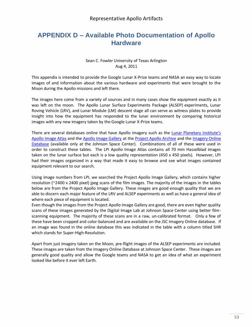
Representative Apollo Artifacts
53
APPENDIX D – Available Photo Documentation of Apollo
Hardware
Sean C. Fowler University of Texas Arlington Aug 4, 2011
This appendix is intended to provide the Google Lunar X-Prize teams and NASA an easy way to locate images of and information about the various hardware and experiments that were brought to the Moon during the Apollo missions and left there. The images here come from a variety of sources and in many cases show the equipment exactly as it was left on the moon. The Apollo Lunar Surface Experiments Package (ALSEP) experiments, Lunar Roving Vehicle (LRV), and Lunar Module (LM) descent stage all can serve as witness plates to provide insight into how the equipment has responded to the lunar environment by comparing historical images with any new imagery taken by the Google Lunar X-Prize teams. There are several databases online that have Apollo imagery such as the Lunar Planetary Institute’s Apollo Image Atlas and the Apollo Image Gallery at the Project Apollo Archive and the Imagery Online Database (available only at the Johnson Space Center). Combinations of all of these were used in order to construct these tables. The LPI Apollo Image Atlas contains all 70 mm Hasselblad images taken on the lunar surface but each is a low quality representation (450 x 450 pixels). However, LPI had their images organized in a way that made it easy to browse and see what images contained equipment relevant to our search. Using image numbers from LPI, we searched the Project Apollo Image Gallery, which contains higher resolution (~2400 x 2400 pixel) jpeg scans of the film images. The majority of the images in the tables below are from the Project Apollo Image Gallery. These images are good enough quality that we are able to discern each major feature of the LRV and ALSEP experiments as well as have a general idea of where each piece of equipment is located. Even though the images from the Project Apollo Image Gallery are good, there are even higher quality scans of these images generated by the Digital Image Lab at Johnson Space Center using better film-scanning equipment. The majority of these scans are in a raw, un-calibrated format. Only a few of these have been cropped and color-balanced and are available on the JSC Imagery Online database. If an image was found in the online database this was indicated in the table with a column titled SHR which stands for Super-High-Resolution. Apart from just imagery taken on the Moon, pre-flight images of the ALSEP experiments are included. These images are taken from the Imagery Online Database at Johnson Space Center. These images are generally good quality and allow the Google teams and NASA to get an idea of what an experiment looked like before it ever left Earth.
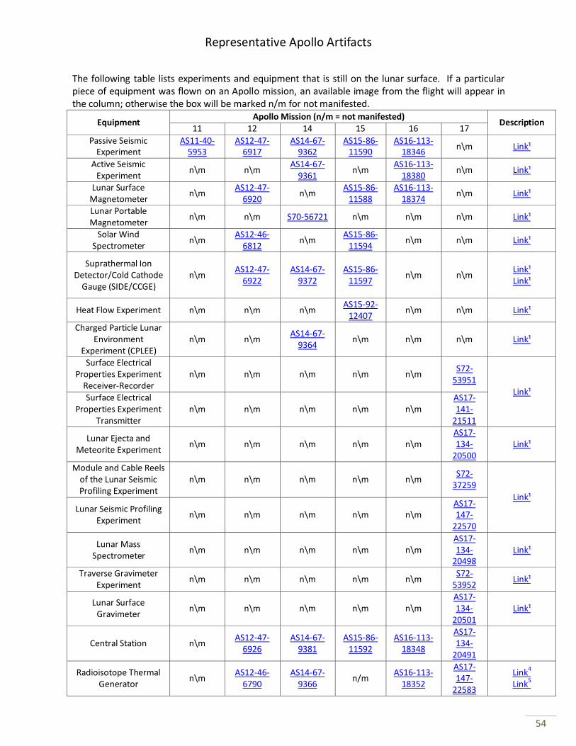
Representative Apollo Artifacts
54
The following table lists experiments and equipment that is still on the lunar surface. If a particular piece of equipment was flown on an Apollo mission, an available image from the flight will appear in the column; otherwise the box will be marked n/m for not manifested.
Equipment Apollo Mission (n/m = not manifested)
Description 11 12 14 15 16 17
Passive Seismic Experiment
AS11-40-5953
AS12-47-6917
AS14-67-9362
AS15-86-11590
AS16-113-18346
n\m Link¹
Active Seismic Experiment
n\m n\m AS14-67-
9361 n\m
AS16-113-18380
n\m Link¹
Lunar Surface Magnetometer
n\m AS12-47-
6920 n\m
AS15-86-11588
AS16-113-18374
n\m Link¹
Lunar Portable Magnetometer
n\m n\m S70-56721 n\m n\m n\m Link¹
Solar Wind Spectrometer
n\m AS12-46-
6812 n\m
AS15-86-11594
n\m n\m Link¹
Suprathermal Ion Detector/Cold Cathode
Gauge (SIDE/CCGE) n\m
AS12-47-6922
AS14-67-9372
AS15-86-11597
n\m n\m Link¹ Link¹
Heat Flow Experiment n\m n\m n\m AS15-92-
12407 n\m n\m Link¹
Charged Particle Lunar Environment
Experiment (CPLEE) n\m n\m
AS14-67-9364
n\m n\m n\m Link¹
Surface Electrical Properties Experiment
Receiver-Recorder n\m n\m n\m n\m n\m
S72-53951
Link¹ Surface Electrical
Properties Experiment Transmitter
n\m n\m n\m n\m n\m AS17-141-
21511
Lunar Ejecta and Meteorite Experiment
n\m n\m n\m n\m n\m AS17-134-
20500 Link¹
Module and Cable Reels of the Lunar Seismic Profiling Experiment
n\m n\m n\m n\m n\m S72-
37259 Link¹
Lunar Seismic Profiling Experiment
n\m n\m n\m n\m n\m AS17-147-
22570
Lunar Mass Spectrometer
n\m n\m n\m n\m n\m AS17-134-
20498 Link¹
Traverse Gravimeter Experiment
n\m n\m n\m n\m n\m S72-
53952 Link¹
Lunar Surface Gravimeter
n\m n\m n\m n\m n\m AS17-134-
20501 Link¹
Central Station n\m AS12-47-
6926 AS14-67-
9381 AS15-86-
11592 AS16-113-
18348
AS17-134-
20491
Radioisotope Thermal Generator
n\m AS12-46-
6790 AS14-67-
9366 n/m
AS16-113-18352
AS17-147-
22583
Link4 Link5
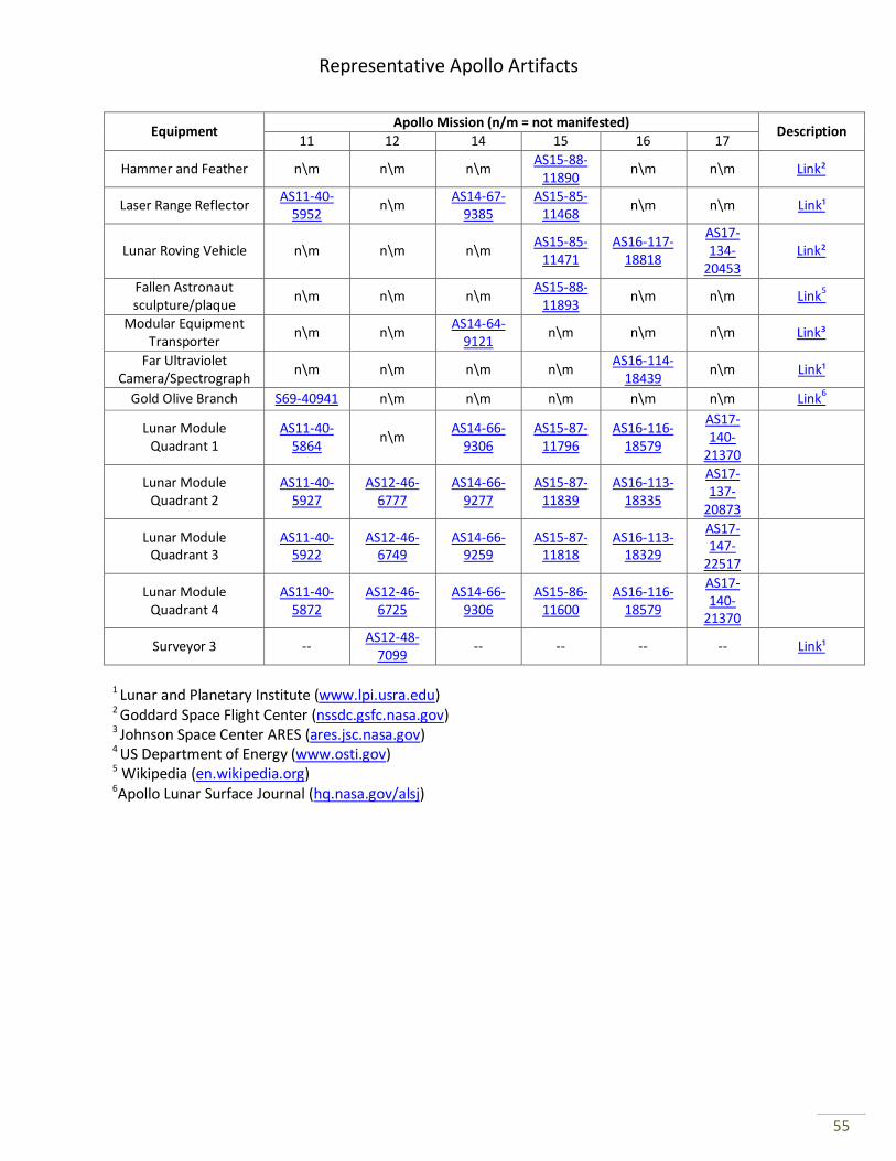
Representative Apollo Artifacts
55
Equipment Apollo Mission (n/m = not manifested)
Description 11 12 14 15 16 17
Hammer and Feather n\m n\m n\m AS15-88-
11890 n\m n\m Link²
Laser Range Reflector AS11-40-
5952 n\m
AS14-67-9385
AS15-85-11468
n\m n\m Link¹
Lunar Roving Vehicle n\m n\m n\m AS15-85-
11471 AS16-117-
18818
AS17-134-
20453 Link²
Fallen Astronaut sculpture/plaque
n\m n\m n\m AS15-88-
11893 n\m n\m Link5
Modular Equipment Transporter
n\m n\m AS14-64-
9121 n\m n\m n\m Link³
Far Ultraviolet Camera/Spectrograph
n\m n\m n\m n\m AS16-114-
18439 n\m Link¹
Gold Olive Branch S69-40941 n\m n\m n\m n\m n\m Link6
Lunar Module Quadrant 1
AS11-40-5864
n\m AS14-66-
9306 AS15-87-
11796 AS16-116-
18579
AS17-140-
21370
Lunar Module Quadrant 2
AS11-40-5927
AS12-46-6777
AS14-66-9277
AS15-87-11839
AS16-113-18335
AS17-137-
20873
Lunar Module Quadrant 3
AS11-40-5922
AS12-46-6749
AS14-66-9259
AS15-87-11818
AS16-113-18329
AS17-147-
22517
Lunar Module Quadrant 4
AS11-40-5872
AS12-46-6725
AS14-66-9306
AS15-86-11600
AS16-116-18579
AS17-140-
21370
Surveyor 3 -- AS12-48-
7099 -- -- -- -- Link¹
1 Lunar and Planetary Institute (www.lpi.usra.edu) 2 Goddard Space Flight Center (nssdc.gsfc.nasa.gov) 3 Johnson Space Center ARES (ares.jsc.nasa.gov) 4 US Department of Energy (www.osti.gov) 5 Wikipedia (en.wikipedia.org) 6Apollo Lunar Surface Journal (hq.nasa.gov/alsj)
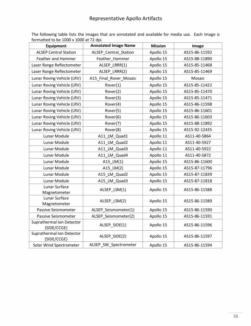
Representative Apollo Artifacts
56
The following table lists the images that are annotated and available for media use. Each image is formatted to be 1000 x 1000 at 72 dpi.
Equipment Annotated Image Name Mission Image
ALSEP Central Station ALSEP_Central_Station Apollo 15 AS15-86-11592
Feather and Hammer Feather_Hammer Apollo 15 AS15-88-11890
Laser Range Reflectometer ALSEP_LRRR(1) Apollo 15 AS15-85-11468
Laser Range Reflectometer ALSEP_LRRR(2) Apollo 15 AS15-85-11469
Lunar Roving Vehicle (LRV) A15_Final_Rover_Mosaic Apollo 15 Mosaic
Lunar Roving Vehicle (LRV) Rover(1) Apollo 15 AS15-85-11422
Lunar Roving Vehicle (LRV) Rover(2) Apollo 15 AS15-85-11470
Lunar Roving Vehicle (LRV) Rover(3) Apollo 15 AS15-85-11471
Lunar Roving Vehicle (LRV) Rover(4) Apollo 15 AS15-86-11598
Lunar Roving Vehicle (LRV) Rover(5) Apollo 15 AS15-86-11601
Lunar Roving Vehicle (LRV) Rover(6) Apollo 15 AS15-86-11603
Lunar Roving Vehicle (LRV) Rover(7) Apollo 15 AS15-88-11892
Lunar Roving Vehicle (LRV) Rover(8) Apollo 15 AS15-92-12435
Lunar Module A11_LM_Quad1 Apollo 11 AS11-40-5864
Lunar Module A11_LM_Quad2 Apollo 11 AS11-40-5927
Lunar Module A11_LM_Quad3 Apollo 11 AS11-40-5922
Lunar Module A11_LM_Quad4 Apollo 11 AS11-40-5872
Lunar Module A15_LM(1) Apollo 15 AS15-86-11600
Lunar Module A15_LM(2) Apollo 15 AS15-87-11796
Lunar Module A15_LM_Quad2 Apollo 15 AS15-87-11839
Lunar Module A15_LM_Quad3 Apollo 15 AS15-87-11818
Lunar Surface Magnetometer
ALSEP_LSM(1) Apollo 15 AS15-86-11588
Lunar Surface Magnetometer
ALSEP_LSM(2) Apollo 15 AS15-86-11589
Passive Seismometer ALSEP_Seismometer(1) Apollo 15 AS15-86-11590
Passive Seismometer ALSEP_Seismometer(2) Apollo 15 AS15-86-11591
Suprathermal Ion Detector (SIDE/CCGE)
ALSEP_SIDE(1) Apollo 15 AS15-86-11596
Suprathermal Ion Detector (SIDE/CCGE)
ALSEP_SIDE(2) Apollo 15 AS15-86-11597
Solar Wind Spectrometer ALSEP_SW_Spectrometer Apollo 15 AS15-86-11594
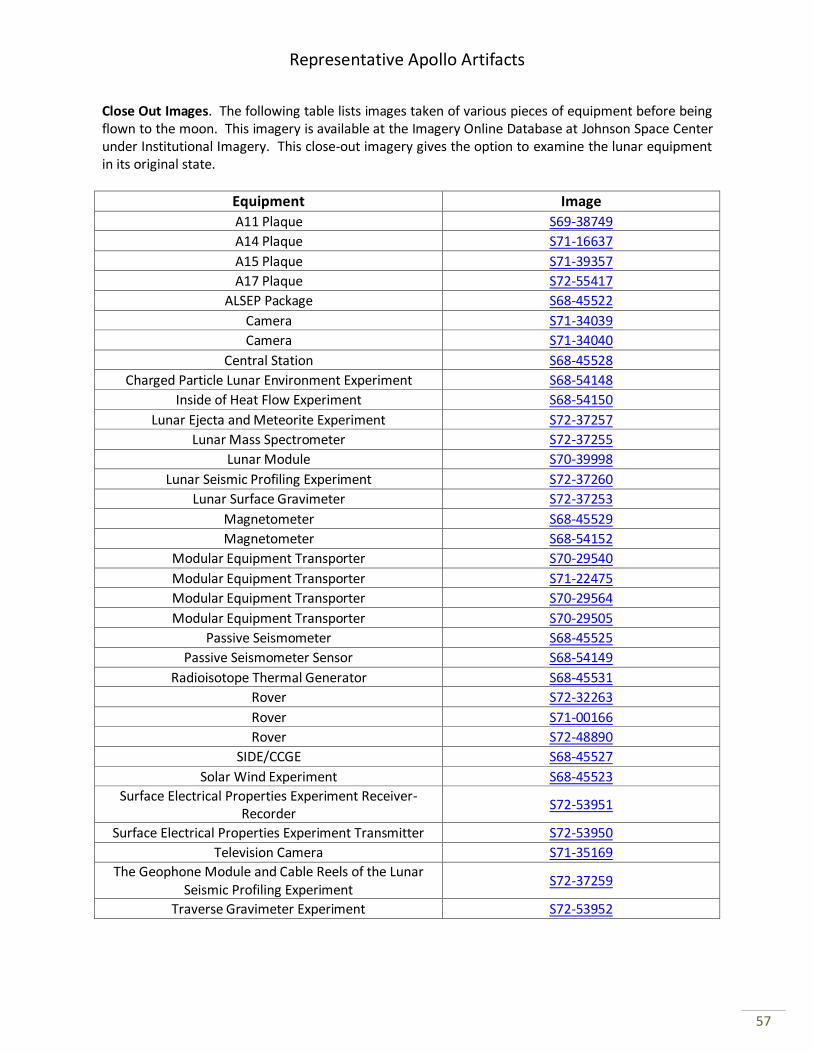
Representative Apollo Artifacts
57
Close Out Images. The following table lists images taken of various pieces of equipment before being flown to the moon. This imagery is available at the Imagery Online Database at Johnson Space Center under Institutional Imagery. This close-out imagery gives the option to examine the lunar equipment in its original state.
Equipment Image
A11 Plaque S69-38749
A14 Plaque S71-16637
A15 Plaque S71-39357
A17 Plaque S72-55417
ALSEP Package S68-45522
Camera S71-34039
Camera S71-34040
Central Station S68-45528
Charged Particle Lunar Environment Experiment S68-54148
Inside of Heat Flow Experiment S68-54150
Lunar Ejecta and Meteorite Experiment S72-37257
Lunar Mass Spectrometer S72-37255
Lunar Module S70-39998
Lunar Seismic Profiling Experiment S72-37260
Lunar Surface Gravimeter S72-37253
Magnetometer S68-45529
Magnetometer S68-54152
Modular Equipment Transporter S70-29540
Modular Equipment Transporter S71-22475
Modular Equipment Transporter S70-29564
Modular Equipment Transporter S70-29505
Passive Seismometer S68-45525
Passive Seismometer Sensor S68-54149
Radioisotope Thermal Generator S68-45531
Rover S72-32263
Rover S71-00166
Rover S72-48890
SIDE/CCGE S68-45527
Solar Wind Experiment S68-45523
Surface Electrical Properties Experiment Receiver-Recorder
S72-53951
Surface Electrical Properties Experiment Transmitter S72-53950
Television Camera S71-35169
The Geophone Module and Cable Reels of the Lunar Seismic Profiling Experiment
S72-37259
Traverse Gravimeter Experiment S72-53952
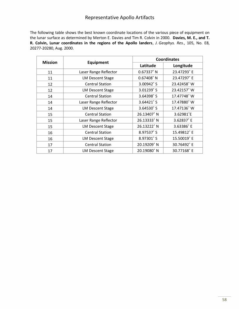
Representative Apollo Artifacts
58
The following table shows the best known coordinate locations of the various piece of equipment on the lunar surface as determined by Merton E. Davies and Tim R. Colvin in 2000. Davies, M. E., and T. R. Colvin, Lunar coordinates in the regions of the Apollo landers, J. Geophys. Res., 105, No. E8, 20277-20280, Aug. 2000.
Mission Equipment Coordinates
Latitude Longitude
11 Laser Range Reflector 0.67337˚ N 23.47293˚ E
11 LM Descent Stage 0.67408˚ N 23.47297˚ E
12 Central Station 3.00942˚ S 23.42458˚ W
12 LM Descent Stage 3.01239˚ S 23.42157˚ W
14 Central Station 3.64398˚ S 17.47748˚ W
14 Laser Range Reflector 3.64421˚ S 17.47880˚ W
14 LM Descent Stage 3.64530˚ S 17.47136˚ W
15 Central Station 26.13407˚ N 3.62981˚E
15 Laser Range Reflector 26.13333˚ N 3.62837˚ E
15 LM Descent Stage 26.13222˚ N 3.63386˚ E
16 Central Station 8.97537˚ S 15.49812˚ E
16 LM Descent Stage 8.97301˚ S 15.50019˚ E
17 Central Station 20.19209˚ N 30.76492˚ E
17 LM Descent Stage 20.19080˚ N 30.77168˚ E
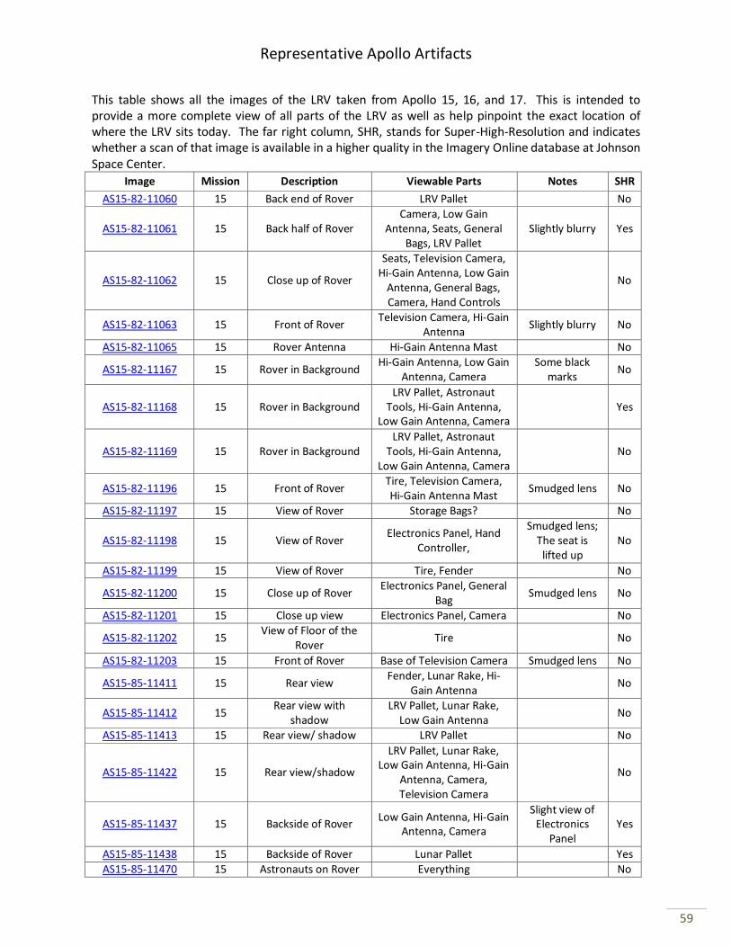
Representative Apollo Artifacts
59
This table shows all the images of the LRV taken from Apollo 15, 16, and 17. This is intended to provide a more complete view of all parts of the LRV as well as help pinpoint the exact location of where the LRV sits today. The far right column, SHR, stands for Super-High-Resolution and indicates whether a scan of that image is available in a higher quality in the Imagery Online database at Johnson Space Center.
Image Mission Description Viewable Parts Notes SHR
AS15-82-11060 15 Back end of Rover LRV Pallet No
AS15-82-11061 15 Back half of Rover Camera, Low Gain
Antenna, Seats, General Bags, LRV Pallet
Slightly blurry Yes
AS15-82-11062 15 Close up of Rover
Seats, Television Camera, Hi-Gain Antenna, Low Gain
Antenna, General Bags, Camera, Hand Controls
No
AS15-82-11063 15 Front of Rover Television Camera, Hi-Gain
Antenna Slightly blurry No
AS15-82-11065 15 Rover Antenna Hi-Gain Antenna Mast No
AS15-82-11167 15 Rover in Background Hi-Gain Antenna, Low Gain
Antenna, Camera Some black
marks No
AS15-82-11168 15 Rover in Background LRV Pallet, Astronaut
Tools, Hi-Gain Antenna, Low Gain Antenna, Camera
Yes
AS15-82-11169 15 Rover in Background LRV Pallet, Astronaut
Tools, Hi-Gain Antenna, Low Gain Antenna, Camera
No
AS15-82-11196 15 Front of Rover Tire, Television Camera, Hi-Gain Antenna Mast
Smudged lens No
AS15-82-11197 15 View of Rover Storage Bags? No
AS15-82-11198 15 View of Rover Electronics Panel, Hand
Controller,
Smudged lens; The seat is
lifted up No
AS15-82-11199 15 View of Rover Tire, Fender No
AS15-82-11200 15 Close up of Rover Electronics Panel, General
Bag Smudged lens No
AS15-82-11201 15 Close up view Electronics Panel, Camera No
AS15-82-11202 15 View of Floor of the
Rover Tire No
AS15-82-11203 15 Front of Rover Base of Television Camera Smudged lens No
AS15-85-11411 15 Rear view Fender, Lunar Rake, Hi-
Gain Antenna No
AS15-85-11412 15 Rear view with
shadow LRV Pallet, Lunar Rake,
Low Gain Antenna No
AS15-85-11413 15 Rear view/ shadow LRV Pallet No
AS15-85-11422 15 Rear view/shadow
LRV Pallet, Lunar Rake, Low Gain Antenna, Hi-Gain
Antenna, Camera, Television Camera
No
AS15-85-11437 15 Backside of Rover Low Gain Antenna, Hi-Gain
Antenna, Camera
Slight view of Electronics
Panel Yes
AS15-85-11438 15 Backside of Rover Lunar Pallet Yes
AS15-85-11470 15 Astronauts on Rover Everything No

Representative Apollo Artifacts
60
Image Mission Description Viewable Parts Notes SHR
AS15-85-11471 15 Astronaut on Rover Everything Yes
AS15-85-11478 15 Hi-Gain Antenna Hi-Gain Antenna No
AS15-85-11480 15 Low Gain Antenna Low Gain Antenna Slightly blurry No
AS15-85-11490 15 Rear view Lunar Pallet No
AS15-85-11491 15 Rover seats Seats Possible Seat
Belt No
AS15-85-11492 15 “Interior view” of
Rover Low Gain Antenna, Camera No
AS15-85-11493 15 Front view of Rover Television Camera, Hi-Gain
Antenna Mast No
AS15-85-11494 15 Front of Rover Television Camera, Hi-Gain
Antenna Mast, Tire No
AS15-86-11598 15 Rover with LM Almost Everything No
AS15-86-11599 15 Rover with LM
Tire Treads, Back of Television Camera, Back of Electronics Panel, Camera, Low Gain Antenna, Hi-Gain
Antenna
Yes
AS15-86-11601 15 Rover with LM Back of Television Camera, Low Gain Antenna, Hi-Gain
Antenna, Camera Yes
AS15-86-11602 15 Rover with LM Back of Television Camera, Low Gain Antenna, Hi-Gain
Antenna, Camera Front View Yes
AS15-86-11603 15 Astronaut by Rover Fender, Hi-Gain Antenna,
Low Gain Antenna, Sample Bags?
Yes
AS15-86-11659 15 Rover in Background Tire Slightly blurry Yes AS15-87-11780 15 Hi-Gain Antenna Hi-Gain Antenna Mast No
AS15-87-11852 15 Distant View LRV Yes
AS15-88-11861 15 Camera Camera No
AS15-88-11862 15 Man's First Wheels on
the Moon Plaque No
AS15-88-11891 15 Solar Panels on Rover Insulation, Solar Panels No
AS15-88-11892 15 Solar Panels on Rover Insulation, Solar Panels No
AS15-88-11899 15 Final Resting place of
LRV Television Camera, Hi-Gain
Antenna In Color No
AS15-88-11900 15 Final Resting place of
LRV
Seat, Television Camera, Hi-Gain Antenna, Low Gain
Antenna In Color No
AS15-88-11901 15 Final Resting place of
LRV
Seats, Television Camera, Hi-Gain Antenna, Low Gain
Antenna In Color Yes
AS15-88-11902 15 Final Resting place of
LRV
Seats, Television Camera, Hi-Gain Antenna, Low Gain
Antenna In Color No
AS15-88-11903 15 Final Resting place of
LRV Seat, Tire, Pallet In Color No
AS15-88-11930 15 View from LM LRV Final Resting
Place for Apollo 15 LRV
Yes
AS15-90-12217 15 Pan of Rover Seats No
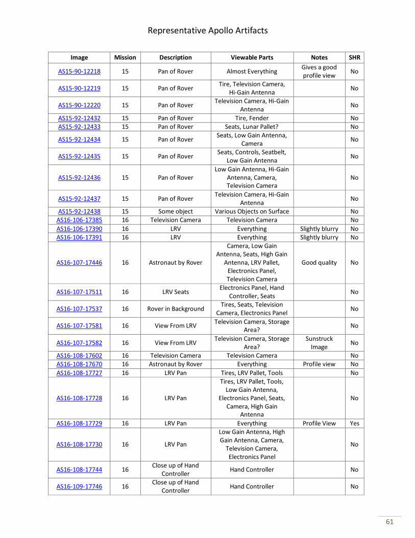
Representative Apollo Artifacts
61
Image Mission Description Viewable Parts Notes SHR
AS15-90-12218 15 Pan of Rover Almost Everything Gives a good profile view
No
AS15-90-12219 15 Pan of Rover Tire, Television Camera,
Hi-Gain Antenna No
AS15-90-12220 15 Pan of Rover Television Camera, Hi-Gain
Antenna No
AS15-92-12432 15 Pan of Rover Tire, Fender No
AS15-92-12433 15 Pan of Rover Seats, Lunar Pallet? No
AS15-92-12434 15 Pan of Rover Seats, Low Gain Antenna,
Camera No
AS15-92-12435 15 Pan of Rover Seats, Controls, Seatbelt,
Low Gain Antenna No
AS15-92-12436 15 Pan of Rover Low Gain Antenna, Hi-Gain
Antenna, Camera, Television Camera
No
AS15-92-12437 15 Pan of Rover Television Camera, Hi-Gain
Antenna No
AS15-92-12438 15 Some object Various Objects on Surface No AS16-106-17385 16 Television Camera Television Camera No
AS16-106-17390 16 LRV Everything Slightly blurry No AS16-106-17391 16 LRV Everything Slightly blurry No
AS16-107-17446 16 Astronaut by Rover
Camera, Low Gain Antenna, Seats, High Gain
Antenna, LRV Pallet, Electronics Panel, Television Camera
Good quality No
AS16-107-17511 16 LRV Seats Electronics Panel, Hand
Controller, Seats No
AS16-107-17537 16 Rover in Background Tires, Seats, Television
Camera, Electronics Panel No
AS16-107-17581 16 View From LRV Television Camera, Storage
Area? No
AS16-107-17582 16 View From LRV Television Camera, Storage
Area? Sunstruck
Image No
AS16-108-17602 16 Television Camera Television Camera No
AS16-108-17670 16 Astronaut by Rover Everything Profile view No
AS16-108-17727 16 LRV Pan Tires, LRV Pallet, Tools No
AS16-108-17728 16 LRV Pan
Tires, LRV Pallet, Tools, Low Gain Antenna,
Electronics Panel, Seats, Camera, High Gain
Antenna
No
AS16-108-17729 16 LRV Pan Everything Profile View Yes
AS16-108-17730 16 LRV Pan
Low Gain Antenna, High Gain Antenna, Camera,
Television Camera, Electronics Panel
No
AS16-108-17744 16 Close up of Hand
Controller Hand Controller No
AS16-109-17746 16 Close up of Hand
Controller Hand Controller No
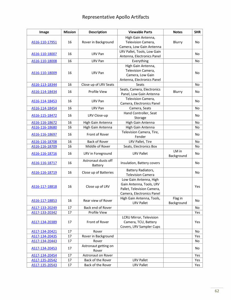
Representative Apollo Artifacts
62
Image Mission Description Viewable Parts Notes SHR
AS16-110-17951 16 Rover in Background High Gain Antenna, Television Camera,
Camera, Low Gain Antenna Blurry No
AS16-110-18007 16 LRV Pan LRV Pallet, Tools, Low Gain Antenna, Electronics Panel
No
AS16-110-18008 16 LRV Pan Everything No
AS16-110-18009 16 LRV Pan
High Gain Antenna, Television Camera, Camera, Low Gain
Antenna, Electronics Panel
No
AS16-113-18344 16 Close up of LRV Seats Seats No
AS16-114-18434 16 Profile View Seats, Camera, Electronics Panel, Low Gain Antenna
Blurry No
AS16-114-18453 16 LRV Pan Television Camera,
Camera, Electronics Panel No
AS16-114-18454 16 LRV Pan Camera, Seats No
AS16-115-18472 16 LRV Close-up Hand Controller, Seat
Storage No
AS16-116-18672 16 High Gain Antenna High Gain Antenna No
AS16-116-18680 16 High Gain Antenna High Gain Antenna No
AS16-116-18697 16 Front of Rover Television Camera, Tire,
Fender No
AS16-116-18708 16 Back of Rover LRV Pallet, Tire No
AS16-116-18709 16 Middle of Rover Seats, Electronics Box No
AS16-116-18716 16 LRV in Foreground LRV Pallet LM in
Background No
AS16-116-18717 16 Astronaut dusts off
Battery Insulation, Battery covers No
AS16-116-18719 16 Close up of Batteries Battery Radiators, Television Camera
No
AS16-117-18818 16 Close up of LRV
Low Gain Antenna, High Gain Antenna, Tools, LRV Pallet, Television Camera, Camera, Electronics Panel
Yes
AS16-117-18853 16 Rear view of Rover High Gain Antenna, Tools,
LRV Pallet Flag in
Background No
AS17-133-20249 17 Back end of Rover No
AS17-133-20342 17 Profile View Yes
AS17-134-20389 17 Front of Rover LCRU Mirror, Television Camera, TCU, Battery
Covers, LRV Sampler Cups Yes
AS17-134-20421 17 Rover No
AS17-134-20435 17 Rover in Background Yes AS17-134-20443 17 Rover No
AS17-134-20453 17 Astronaut getting on
Rover No
AS17-134-20454 17 Astronaut on Rover Yes
AS17-135-20542 17 Back of the Rover LRV Pallet Yes
AS17-135-20543 17 Back of the Rover LRV Pallet Yes
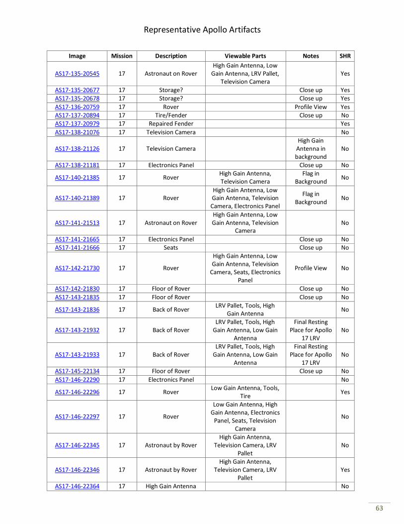
Representative Apollo Artifacts
63
Image Mission Description Viewable Parts Notes SHR
AS17-135-20545 17 Astronaut on Rover High Gain Antenna, Low
Gain Antenna, LRV Pallet, Television Camera
Yes
AS17-135-20677 17 Storage? Close up Yes AS17-135-20678 17 Storage? Close up Yes
AS17-136-20759 17 Rover Profile View Yes AS17-137-20894 17 Tire/Fender Close up No
AS17-137-20979 17 Repaired Fender Yes
AS17-138-21076 17 Television Camera No
AS17-138-21126 17 Television Camera High Gain
Antenna in background
No
AS17-138-21181 17 Electronics Panel Close up No
AS17-140-21385 17 Rover High Gain Antenna, Television Camera
Flag in Background
No
AS17-140-21389 17 Rover High Gain Antenna, Low Gain Antenna, Television Camera, Electronics Panel
Flag in Background
No
AS17-141-21513 17 Astronaut on Rover High Gain Antenna, Low Gain Antenna, Television
Camera No
AS17-141-21665 17 Electronics Panel Close up No
AS17-141-21666 17 Seats Close up No
AS17-142-21730 17 Rover
High Gain Antenna, Low Gain Antenna, Television
Camera, Seats, Electronics Panel
Profile View No
AS17-142-21830 17 Floor of Rover Close up No
AS17-143-21835 17 Floor of Rover Close up No
AS17-143-21836 17 Back of Rover LRV Pallet, Tools, High
Gain Antenna No
AS17-143-21932 17 Back of Rover LRV Pallet, Tools, High
Gain Antenna, Low Gain Antenna
Final Resting Place for Apollo
17 LRV No
AS17-143-21933 17 Back of Rover LRV Pallet, Tools, High
Gain Antenna, Low Gain Antenna
Final Resting Place for Apollo
17 LRV No
AS17-145-22134 17 Floor of Rover Close up No
AS17-146-22290 17 Electronics Panel No
AS17-146-22296 17 Rover Low Gain Antenna, Tools,
Tire Yes
AS17-146-22297 17 Rover
Low Gain Antenna, High Gain Antenna, Electronics
Panel, Seats, Television Camera
No
AS17-146-22345 17 Astronaut by Rover High Gain Antenna,
Television Camera, LRV Pallet
No
AS17-146-22346 17 Astronaut by Rover High Gain Antenna,
Television Camera, LRV Pallet
Yes
AS17-146-22364 17 High Gain Antenna No
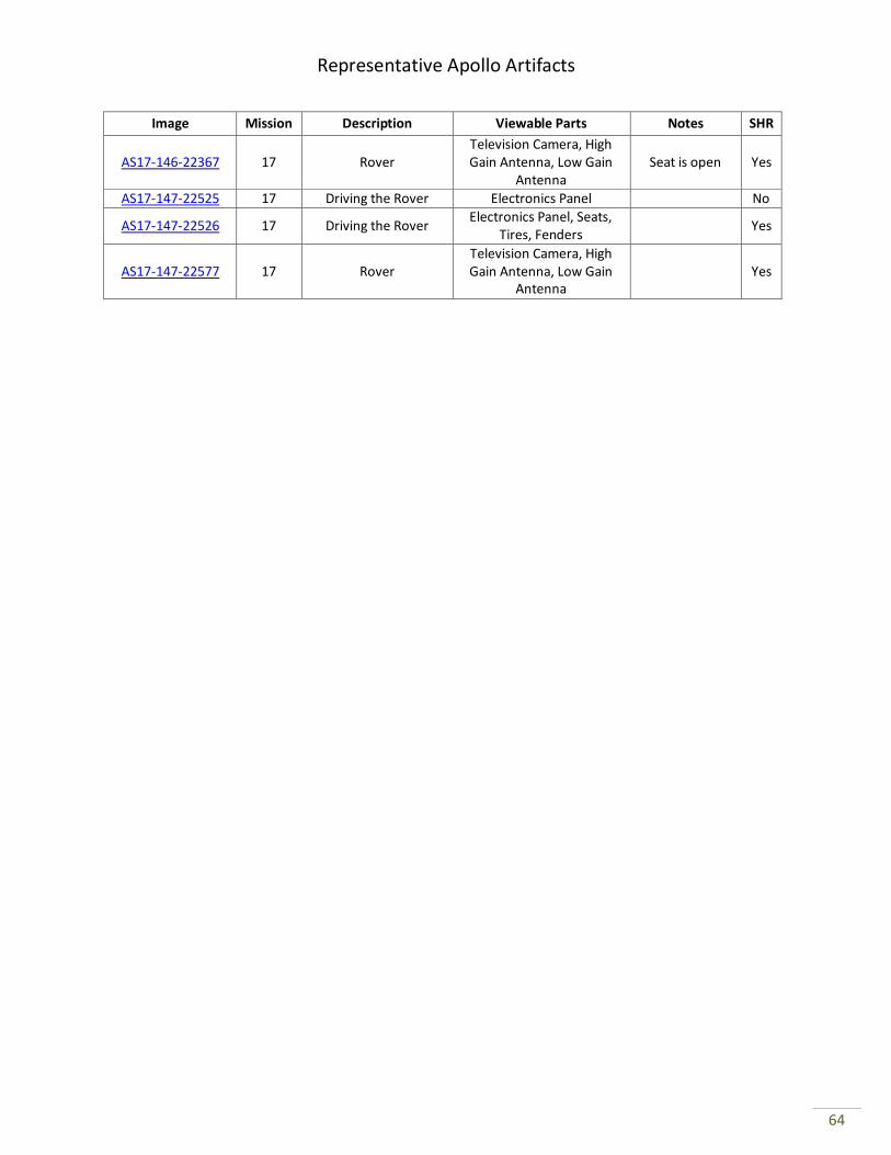
Representative Apollo Artifacts
64
Image Mission Description Viewable Parts Notes SHR
AS17-146-22367 17 Rover Television Camera, High Gain Antenna, Low Gain
Antenna Seat is open Yes
AS17-147-22525 17 Driving the Rover Electronics Panel No
AS17-147-22526 17 Driving the Rover Electronics Panel, Seats,
Tires, Fenders Yes
AS17-147-22577 17 Rover Television Camera, High Gain Antenna, Low Gain
Antenna Yes
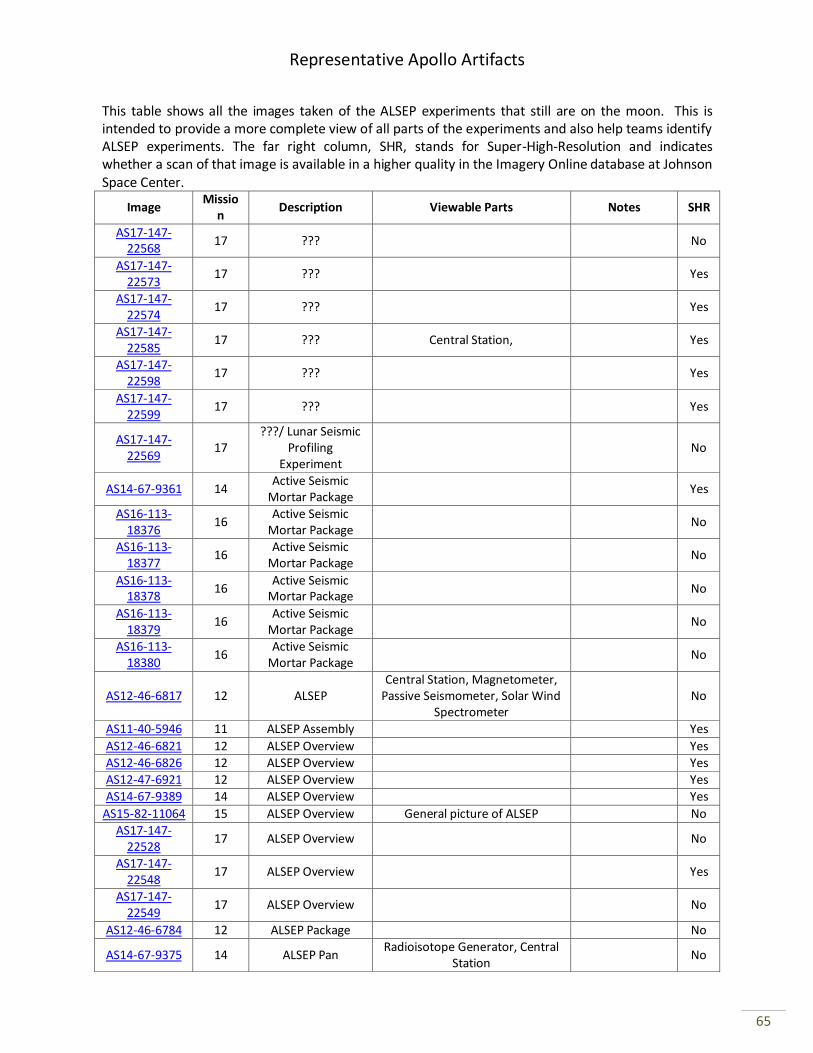
Representative Apollo Artifacts
65
This table shows all the images taken of the ALSEP experiments that still are on the moon. This is intended to provide a more complete view of all parts of the experiments and also help teams identify ALSEP experiments. The far right column, SHR, stands for Super-High-Resolution and indicates whether a scan of that image is available in a higher quality in the Imagery Online database at Johnson Space Center.
Image Missio
n Description Viewable Parts Notes SHR
AS17-147-22568
17 ??? No
AS17-147-22573
17 ??? Yes
AS17-147-22574
17 ??? Yes
AS17-147-22585
17 ??? Central Station, Yes
AS17-147-22598
17 ??? Yes
AS17-147-22599
17 ??? Yes
AS17-147-22569
17 ???/ Lunar Seismic
Profiling Experiment
No
AS14-67-9361 14 Active Seismic
Mortar Package Yes
AS16-113-18376
16 Active Seismic
Mortar Package No
AS16-113-18377
16 Active Seismic
Mortar Package No
AS16-113-18378
16 Active Seismic
Mortar Package No
AS16-113-18379
16 Active Seismic
Mortar Package No
AS16-113-18380
16 Active Seismic
Mortar Package No
AS12-46-6817 12 ALSEP Central Station, Magnetometer,
Passive Seismometer, Solar Wind Spectrometer
No
AS11-40-5946 11 ALSEP Assembly Yes
AS12-46-6821 12 ALSEP Overview Yes AS12-46-6826 12 ALSEP Overview Yes
AS12-47-6921 12 ALSEP Overview Yes
AS14-67-9389 14 ALSEP Overview Yes
AS15-82-11064 15 ALSEP Overview General picture of ALSEP No
AS17-147-22528
17 ALSEP Overview No
AS17-147-22548
17 ALSEP Overview Yes
AS17-147-22549
17 ALSEP Overview No
AS12-46-6784 12 ALSEP Package No
AS14-67-9375 14 ALSEP Pan Radioisotope Generator, Central
Station No
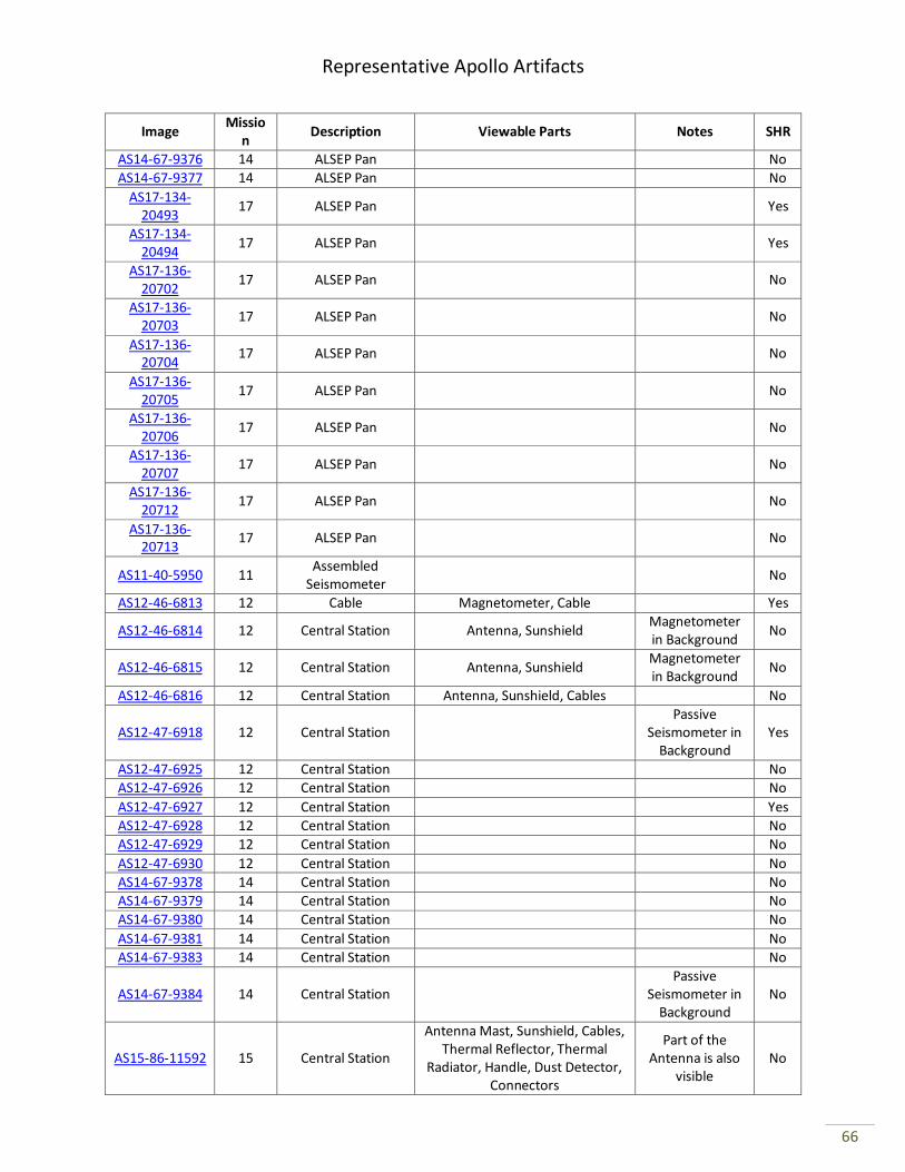
Representative Apollo Artifacts
66
Image Missio
n Description Viewable Parts Notes SHR
AS14-67-9376 14 ALSEP Pan No
AS14-67-9377 14 ALSEP Pan No
AS17-134-20493
17 ALSEP Pan Yes
AS17-134-20494
17 ALSEP Pan Yes
AS17-136-20702
17 ALSEP Pan No
AS17-136-20703
17 ALSEP Pan No
AS17-136-20704
17 ALSEP Pan No
AS17-136-20705
17 ALSEP Pan No
AS17-136-20706
17 ALSEP Pan No
AS17-136-20707
17 ALSEP Pan No
AS17-136-20712
17 ALSEP Pan No
AS17-136-20713
17 ALSEP Pan No
AS11-40-5950 11 Assembled
Seismometer No
AS12-46-6813 12 Cable Magnetometer, Cable Yes
AS12-46-6814 12 Central Station Antenna, Sunshield Magnetometer in Background
No
AS12-46-6815 12 Central Station Antenna, Sunshield Magnetometer in Background
No
AS12-46-6816 12 Central Station Antenna, Sunshield, Cables No
AS12-47-6918 12 Central Station Passive
Seismometer in Background
Yes
AS12-47-6925 12 Central Station No
AS12-47-6926 12 Central Station No
AS12-47-6927 12 Central Station Yes
AS12-47-6928 12 Central Station No AS12-47-6929 12 Central Station No
AS12-47-6930 12 Central Station No
AS14-67-9378 14 Central Station No AS14-67-9379 14 Central Station No
AS14-67-9380 14 Central Station No
AS14-67-9381 14 Central Station No
AS14-67-9383 14 Central Station No
AS14-67-9384 14 Central Station Passive
Seismometer in Background
No
AS15-86-11592 15 Central Station
Antenna Mast, Sunshield, Cables, Thermal Reflector, Thermal
Radiator, Handle, Dust Detector, Connectors
Part of the Antenna is also
visible No

Representative Apollo Artifacts
67
Image Missio
n Description Viewable Parts Notes SHR
AS16-113-18348
16 Central Station
Antenna, Sunshield, Cables, Thermal Reflector, Thermal
Radiator, Handle, Dust Detector, Connectors
Note severed heat flow cable at the back of Central Station
No
AS16-113-18356
16 Central Station Antenna, Sunshield, Cables, Thermal Reflector, Thermal
Radiator, Handle, Connectors No
AS16-113-18357
16 Central Station Antenna, Sunshield, Cables, Thermal Reflector, Thermal
Radiator, Dust Detector
Active Seismometer in
background No
AS16-113-18358
16 Central Station Sunshield, Cables, Thermal
Reflector, Thermal Radiator, Dust Detector
Active Seismometer
and LM in background
No
AS16-113-18375
16 Central Station Antenna, Sunshield Rover in
Background No
AS17-134-20489
17 Central Station No
AS17-134-20490
17 Central Station Lower portion of
north side Yes
AS17-134-20491
17 Central Station No
AS17-147-22586
17 Central Station Yes
AS17-147-22587
17 Central Station Yes
AS14-67-9364 14 Charged Particle
Lunar Environment Experiment
No
AS14-67-9365 14 Charged Particle
Lunar Environment Experiment
Central Station and Modular Equipment
Transporter in Background
Yes
AS11-40-5963 11 Core Tube No
AS12-46-6818 12 Deploying ALSEP Top of RTG in Foreground
Yes
AS16-113-18345
16 Experiments? ??? No
AS15-87-11860 15 Heat Flow
Experiment Probe No
AS15-92-12406 15 Heat Flow
Experiment Probe
RTG in background?
No
AS15-92-12407 15 Heat Flow
Experiment Drill Rack, Probe No
AS15-92-12408 15 Heat Flow
Experiment Probe, Borestem No
AS15-92-12409 15 Heat Flow
Experiment No
AS17-134-20495
17 Heat Flow Probe No
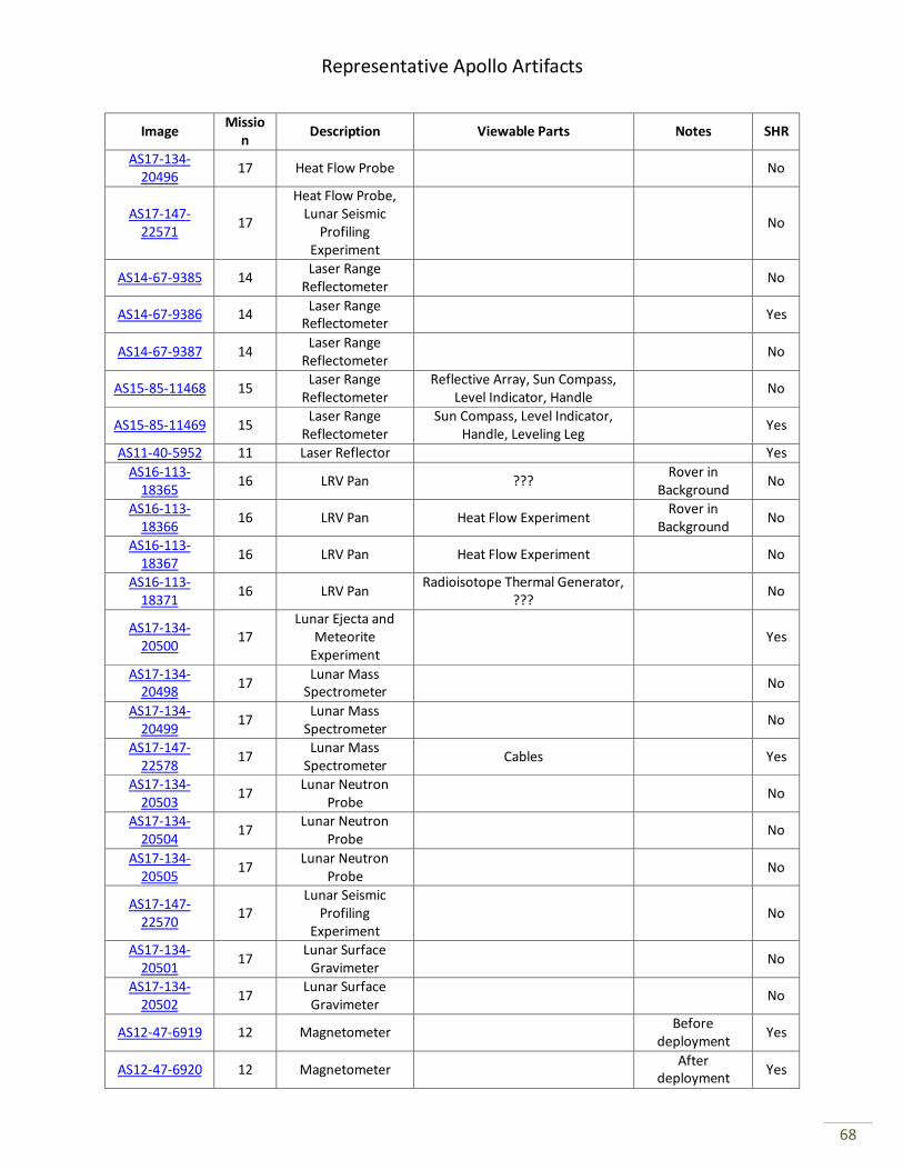
Representative Apollo Artifacts
68
Image Missio
n Description Viewable Parts Notes SHR
AS17-134-20496
17 Heat Flow Probe No
AS17-147-22571
17
Heat Flow Probe, Lunar Seismic
Profiling Experiment
No
AS14-67-9385 14 Laser Range
Reflectometer No
AS14-67-9386 14 Laser Range
Reflectometer Yes
AS14-67-9387 14 Laser Range
Reflectometer No
AS15-85-11468 15 Laser Range
Reflectometer Reflective Array, Sun Compass,
Level Indicator, Handle No
AS15-85-11469 15 Laser Range
Reflectometer Sun Compass, Level Indicator,
Handle, Leveling Leg Yes
AS11-40-5952 11 Laser Reflector Yes
AS16-113-18365
16 LRV Pan ??? Rover in
Background No
AS16-113-18366
16 LRV Pan Heat Flow Experiment Rover in
Background No
AS16-113-18367
16 LRV Pan Heat Flow Experiment No
AS16-113-18371
16 LRV Pan Radioisotope Thermal Generator,
??? No
AS17-134-20500
17 Lunar Ejecta and
Meteorite Experiment
Yes
AS17-134-20498
17 Lunar Mass
Spectrometer No
AS17-134-20499
17 Lunar Mass
Spectrometer No
AS17-147-22578
17 Lunar Mass
Spectrometer Cables Yes
AS17-134-20503
17 Lunar Neutron
Probe No
AS17-134-20504
17 Lunar Neutron
Probe No
AS17-134-20505
17 Lunar Neutron
Probe No
AS17-147-22570
17 Lunar Seismic
Profiling Experiment
No
AS17-134-20501
17 Lunar Surface
Gravimeter No
AS17-134-20502
17 Lunar Surface
Gravimeter No
AS12-47-6919 12 Magnetometer Before
deployment Yes
AS12-47-6920 12 Magnetometer After
deployment Yes
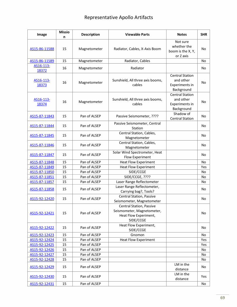
Representative Apollo Artifacts
69
Image Missio
n Description Viewable Parts Notes SHR
AS15-86-11588 15 Magnetometer Radiator, Cables, X-Axis Boom
Not sure whether the
boom is the X, Y, or Z axis
No
AS15-86-11589 15 Magnetometer Radiator, Cables No AS16-113-
18372 16 Magnetometer Radiator No
AS16-113-18373
16 Magnetometer Sunshield, All three axis booms,
cables
Central Station and other
Experiments in Background
No
AS16-113-18374
16 Magnetometer Sunshield, All three axis booms,
cables
Central Station and other
Experiments in Background
No
AS15-87-11843 15 Pan of ALSEP Passive Seismometer, ???? Shadow of
Central Station No
AS15-87-11844 15 Pan of ALSEP Passive Seismometer, Central
Station No
AS15-87-11845 15 Pan of ALSEP Central Station, Cables,
Magnetometer No
AS15-87-11846 15 Pan of ALSEP Central Station, Cables,
Magnetometer No
AS15-87-11847 15 Pan of ALSEP Solar Wind Spectrometer, Heat
Flow Experiment No
AS15-87-11848 15 Pan of ALSEP Heat Flow Experiment No AS15-87-11849 15 Pan of ALSEP Heat Flow Experiment Yes
AS15-87-11850 15 Pan of ALSEP SIDE/CCGE No
AS15-87-11851 15 Pan of ALSEP SIDE/CCGE, ???? No
AS15-87-11857 15 Pan of ALSEP Laser Range Reflectometer No
AS15-87-11858 15 Pan of ALSEP Laser Range Reflectometer,
Carrying bag?, Tools? No
AS15-92-12420 15 Pan of ALSEP Central Station, Passive
Seismometer, Magnetometer No
AS15-92-12421 15 Pan of ALSEP
Central Station, Passive Seismometer, Magnetometer,
Heat Flow Experiment, SIDE/CCGE
No
AS15-92-12422 15 Pan of ALSEP Heat Flow Experiment,
SIDE/CCGE No
AS15-92-12423 15 Pan of ALSEP Gnomon No
AS15-92-12424 15 Pan of ALSEP Heat Flow Experiment Yes AS15-92-12425 15 Pan of ALSEP Yes
AS15-92-12426 15 Pan of ALSEP No
AS15-92-12427 15 Pan of ALSEP No AS15-92-12428 15 Pan of ALSEP No
AS15-92-12429 15 Pan of ALSEP LM in the distance
No
AS15-92-12430 15 Pan of ALSEP LM in the distance
Yes
AS15-92-12431 15 Pan of ALSEP No
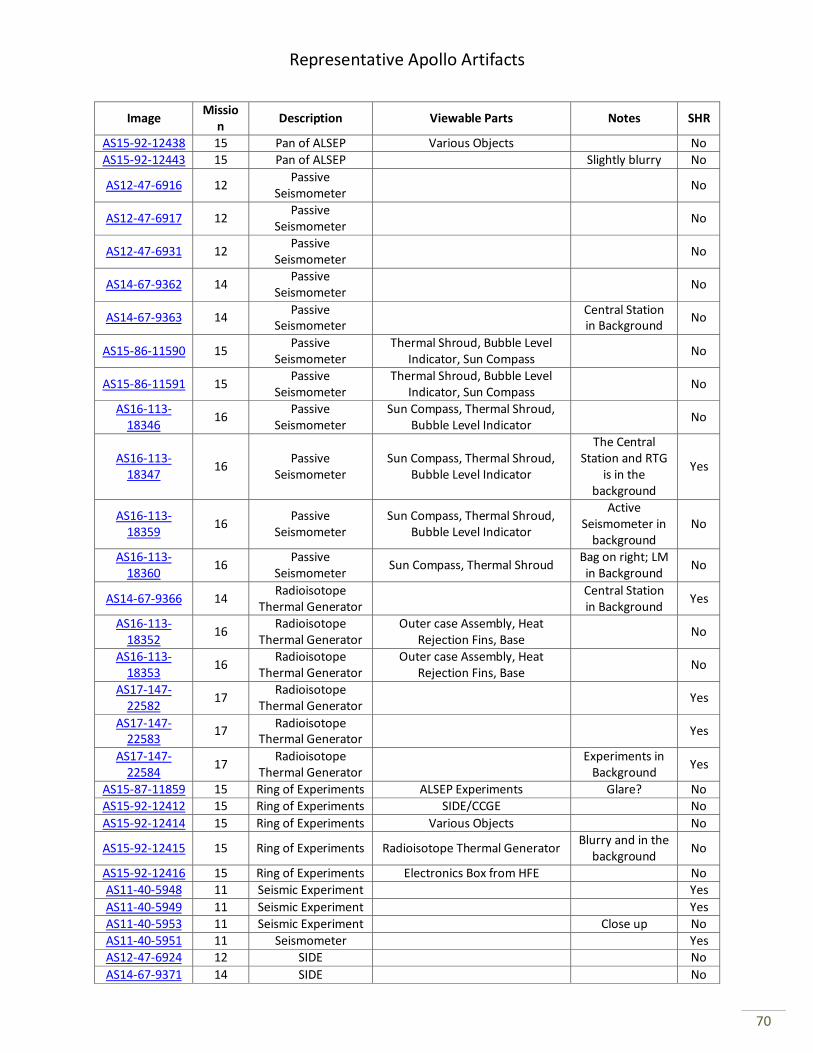
Representative Apollo Artifacts
70
Image Missio
n Description Viewable Parts Notes SHR
AS15-92-12438 15 Pan of ALSEP Various Objects No
AS15-92-12443 15 Pan of ALSEP Slightly blurry No
AS12-47-6916 12 Passive
Seismometer No
AS12-47-6917 12 Passive
Seismometer No
AS12-47-6931 12 Passive
Seismometer No
AS14-67-9362 14 Passive
Seismometer No
AS14-67-9363 14 Passive
Seismometer
Central Station in Background
No
AS15-86-11590 15 Passive
Seismometer Thermal Shroud, Bubble Level
Indicator, Sun Compass No
AS15-86-11591 15 Passive
Seismometer Thermal Shroud, Bubble Level
Indicator, Sun Compass No
AS16-113-18346
16 Passive
Seismometer Sun Compass, Thermal Shroud,
Bubble Level Indicator No
AS16-113-18347
16 Passive
Seismometer Sun Compass, Thermal Shroud,
Bubble Level Indicator
The Central Station and RTG
is in the background
Yes
AS16-113-18359
16 Passive
Seismometer Sun Compass, Thermal Shroud,
Bubble Level Indicator
Active Seismometer in
background No
AS16-113-18360
16 Passive
Seismometer Sun Compass, Thermal Shroud
Bag on right; LM in Background
No
AS14-67-9366 14 Radioisotope
Thermal Generator
Central Station in Background
Yes
AS16-113-18352
16 Radioisotope
Thermal Generator Outer case Assembly, Heat
Rejection Fins, Base No
AS16-113-18353
16 Radioisotope
Thermal Generator Outer case Assembly, Heat
Rejection Fins, Base No
AS17-147-22582
17 Radioisotope
Thermal Generator Yes
AS17-147-22583
17 Radioisotope
Thermal Generator Yes
AS17-147-22584
17 Radioisotope
Thermal Generator
Experiments in Background
Yes
AS15-87-11859 15 Ring of Experiments ALSEP Experiments Glare? No
AS15-92-12412 15 Ring of Experiments SIDE/CCGE No
AS15-92-12414 15 Ring of Experiments Various Objects No
AS15-92-12415 15 Ring of Experiments Radioisotope Thermal Generator Blurry and in the
background No
AS15-92-12416 15 Ring of Experiments Electronics Box from HFE No AS11-40-5948 11 Seismic Experiment Yes
AS11-40-5949 11 Seismic Experiment Yes
AS11-40-5953 11 Seismic Experiment Close up No AS11-40-5951 11 Seismometer Yes
AS12-47-6924 12 SIDE No
AS14-67-9371 14 SIDE No
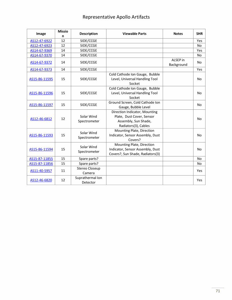
Representative Apollo Artifacts
71
Image Missio
n Description Viewable Parts Notes SHR
AS12-47-6922 12 SIDE/CCGE Yes
AS12-47-6923 12 SIDE/CCGE No
AS14-67-9369 14 SIDE/CCGE Yes AS14-67-9370 14 SIDE/CCGE No
AS14-67-9372 14 SIDE/CCGE ALSEP in
Background No
AS14-67-9373 14 SIDE/CCGE Yes
AS15-86-11595 15 SIDE/CCGE Cold Cathode Ion Gauge, Bubble
Level, Universal Handling Tool Socket
No
AS15-86-11596 15 SIDE/CCGE Cold Cathode Ion Gauge, Bubble
Level, Universal Handling Tool Socket
No
AS15-86-11597 15 SIDE/CCGE Ground Screen, Cold Cathode Ion
Gauge, Bubble Level No
AS12-46-6812 12 Solar Wind
Spectrometer
Direction Indicator, Mounting Plate, Dust Cover, Sensor
Assembly, Sun Shade, Radiators(3), Cables
No
AS15-86-11593 15 Solar Wind
Spectrometer
Mounting Plate, Direction Indicator, Sensor Assembly, Dust
Covers? No
AS15-86-11594 15 Solar Wind
Spectrometer
Mounting Plate, Direction Indicator, Sensor Assembly, Dust Covers?, Sun Shade, Radiators(3)
No
AS15-87-11855 15 Spare parts? No
AS15-87-11856 15 Spare parts? No
AS11-40-5957 11 Stereo Closeup
Camera Yes
AS12-46-6820 12 Suprathermal Ion
Detector Yes
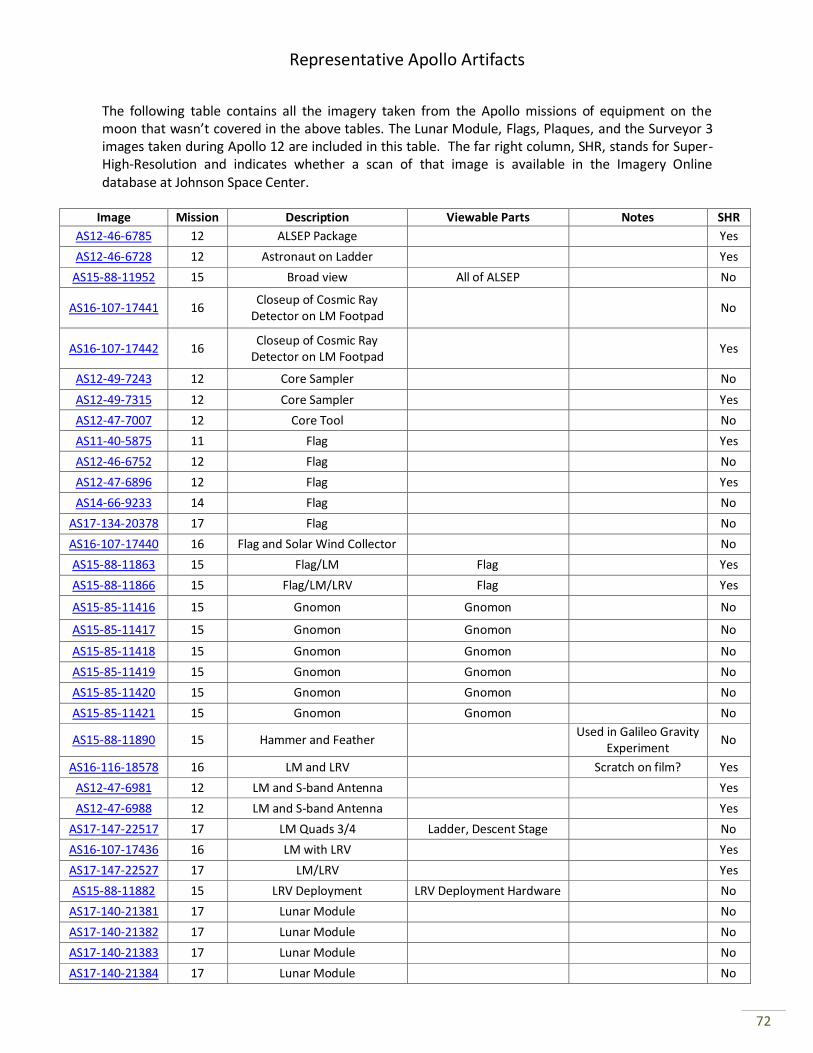
Representative Apollo Artifacts
72
The following table contains all the imagery taken from the Apollo missions of equipment on the moon that wasn’t covered in the above tables. The Lunar Module, Flags, Plaques, and the Surveyor 3 images taken during Apollo 12 are included in this table. The far right column, SHR, stands for Super-High-Resolution and indicates whether a scan of that image is available in the Imagery Online database at Johnson Space Center.
Image Mission Description Viewable Parts Notes SHR
AS12-46-6785 12 ALSEP Package Yes
AS12-46-6728 12 Astronaut on Ladder Yes
AS15-88-11952 15 Broad view All of ALSEP No
AS16-107-17441 16 Closeup of Cosmic Ray
Detector on LM Footpad No
AS16-107-17442 16 Closeup of Cosmic Ray
Detector on LM Footpad Yes
AS12-49-7243 12 Core Sampler No
AS12-49-7315 12 Core Sampler Yes
AS12-47-7007 12 Core Tool No
AS11-40-5875 11 Flag Yes
AS12-46-6752 12 Flag No
AS12-47-6896 12 Flag Yes
AS14-66-9233 14 Flag No
AS17-134-20378 17 Flag No
AS16-107-17440 16 Flag and Solar Wind Collector No
AS15-88-11863 15 Flag/LM Flag Yes
AS15-88-11866 15 Flag/LM/LRV Flag Yes
AS15-85-11416 15 Gnomon Gnomon No
AS15-85-11417 15 Gnomon Gnomon No
AS15-85-11418 15 Gnomon Gnomon No
AS15-85-11419 15 Gnomon Gnomon No
AS15-85-11420 15 Gnomon Gnomon No
AS15-85-11421 15 Gnomon Gnomon No
AS15-88-11890 15 Hammer and Feather
Used in Galileo Gravity Experiment
No
AS16-116-18578 16 LM and LRV Scratch on film? Yes
AS12-47-6981 12 LM and S-band Antenna Yes
AS12-47-6988 12 LM and S-band Antenna Yes
AS17-147-22517 17 LM Quads 3/4 Ladder, Descent Stage No
AS16-107-17436 16 LM with LRV Yes
AS17-147-22527 17 LM/LRV Yes
AS15-88-11882 15 LRV Deployment LRV Deployment Hardware No
AS17-140-21381 17 Lunar Module No
AS17-140-21382 17 Lunar Module No
AS17-140-21383 17 Lunar Module No
AS17-140-21384 17 Lunar Module No
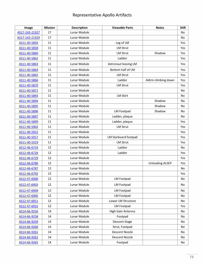
Representative Apollo Artifacts
73
Image Mission Description Viewable Parts Notes SHR
AS17-143-21927 17 Lunar Module No
AS17-143-21929 17 Lunar Module No
AS11-40-5850 11 Lunar Module Leg of LM Yes
AS11-40-5858 11 Lunar Module LM Strut Yes
AS11-40-5860 11 Lunar Module LM Strut Shadow Yes
AS11-40-5862 11 Lunar Module Ladder Yes
AS11-40-5863 11 Lunar Module Astronaut leaving LM Yes
AS11-40-5864 11 Lunar Module Bottom half of LM Yes
AS11-40-5865 11 Lunar Module LM Strut Yes
AS11-40-5866 11 Lunar Module Ladder Aldrin climbing down Yes
AS11-40-5870 11 Lunar Module LM Strut Yes
AS11-40-5871 11 Lunar Module No
AS11-40-5893 11 Lunar Module LM Skirt No
AS11-40-5894 11 Lunar Module Shadow No
AS11-40-5895 11 Lunar Module Shadow No
AS11-40-5896 11 Lunar Module LM Footpad Shadow No
AS11-40-5897 11 Lunar Module Ladder, plaque No
AS11-40-5899 11 Lunar Module Ladder, plaque Yes
AS11-40-5902 11 Lunar Module LM Strut Yes
AS11-40-5915 11 Lunar Module Yes
AS11-40-5917 11 Lunar Module LM Starboard footpad Yes
AS11-40-5919 11 Lunar Module LM Strut Yes
AS12-46-6724 12 Lunar Module Ladder No
AS12-46-6726 12 Lunar Module Ladder Yes
AS12-46-6729 12 Lunar Module Yes
AS12-46-6786 12 Lunar Module Unloading ALSEP Yes
AS12-46-6787 12 Lunar Module No
AS12-46-6792 12 Lunar Module Yes
AS12-47-6900 12 Lunar Module LM Footpad No
AS12-47-6903 12 Lunar Module LM Footpad No
AS12-47-6904 12 Lunar Module LM Footpad No
AS12-47-6905 12 Lunar Module LM Footpad No
AS12-47-6911 12 Lunar Module Lower LM Structure No
AS12-47-6915 12 Lunar Module LM Footpad Yes
AS14-66-9256 14 Lunar Module High Gain Antenna No
AS14-66-9258 14 Lunar Module Footpad No
AS14-66-9259 14 Lunar Module Descent Stage No
AS14-66-9260 14 Lunar Module Strut, Footpad No
AS14-66-9261 14 Lunar Module Descent Nozzle No
AS14-66-9262 14 Lunar Module Descent Nozzle No
AS14-66-9265 14 Lunar Module Footpad No
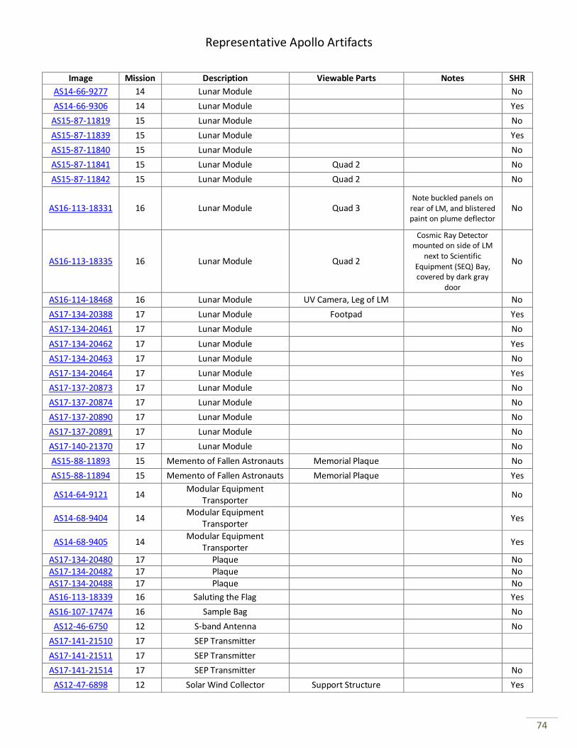
Representative Apollo Artifacts
74
Image Mission Description Viewable Parts Notes SHR
AS14-66-9277 14 Lunar Module No
AS14-66-9306 14 Lunar Module Yes
AS15-87-11819 15 Lunar Module No
AS15-87-11839 15 Lunar Module Yes
AS15-87-11840 15 Lunar Module No
AS15-87-11841 15 Lunar Module Quad 2 No
AS15-87-11842 15 Lunar Module Quad 2 No
AS16-113-18331 16 Lunar Module Quad 3 Note buckled panels on
rear of LM, and blistered paint on plume deflector
No
AS16-113-18335 16 Lunar Module Quad 2
Cosmic Ray Detector mounted on side of LM
next to Scientific Equipment (SEQ) Bay, covered by dark gray
door
No
AS16-114-18468 16 Lunar Module UV Camera, Leg of LM No
AS17-134-20388 17 Lunar Module Footpad Yes
AS17-134-20461 17 Lunar Module No
AS17-134-20462 17 Lunar Module Yes
AS17-134-20463 17 Lunar Module No
AS17-134-20464 17 Lunar Module Yes
AS17-137-20873 17 Lunar Module No
AS17-137-20874 17 Lunar Module No
AS17-137-20890 17 Lunar Module No
AS17-137-20891 17 Lunar Module No
AS17-140-21370 17 Lunar Module No
AS15-88-11893 15 Memento of Fallen Astronauts Memorial Plaque No
AS15-88-11894 15 Memento of Fallen Astronauts Memorial Plaque Yes
AS14-64-9121 14 Modular Equipment
Transporter No
AS14-68-9404 14 Modular Equipment
Transporter Yes
AS14-68-9405 14 Modular Equipment
Transporter Yes
AS17-134-20480 17 Plaque No
AS17-134-20482 17 Plaque No AS17-134-20488 17 Plaque No
AS16-113-18339 16 Saluting the Flag Yes
AS16-107-17474 16 Sample Bag No
AS12-46-6750 12 S-band Antenna No
AS17-141-21510 17 SEP Transmitter
AS17-141-21511 17 SEP Transmitter
AS17-141-21514 17 SEP Transmitter No
AS12-47-6898 12 Solar Wind Collector Support Structure Yes
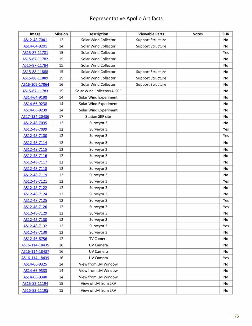
Representative Apollo Artifacts
75
Image Mission Description Viewable Parts Notes SHR
AS12-48-7041 12 Solar Wind Collector Support Structure No
AS14-64-9201 14 Solar Wind Collector Support Structure No
AS15-87-11781 15 Solar Wind Collector Yes
AS15-87-11782 15 Solar Wind Collector No
AS15-87-11784 15 Solar Wind Collector No
AS15-88-11888 15 Solar Wind Collector Support Structure No
AS15-88-11889 15 Solar Wind Collector Support Structure No
AS16-109-17864 16 Solar Wind Collector Support Structure No
AS15-87-11783 15 Solar Wind Collector/ALSEP No
AS14-64-9198 14 Solar Wind Experiment No
AS14-66-9238 14 Solar Wind Experiment No
AS14-66-9239 14 Solar Wind Experiment No
AS17-134-20436 17 Station SEP site No
AS12-48-7095 12 Surveyor 3 No
AS12-48-7099 12 Surveyor 3 Yes
AS12-48-7100 12 Surveyor 3 Yes
AS12-48-7114 12 Surveyor 3 No
AS12-48-7115 12 Surveyor 3 No
AS12-48-7116 12 Surveyor 3 No
AS12-48-7117 12 Surveyor 3 No
AS12-48-7118 12 Surveyor 3 No
AS12-48-7119 12 Surveyor 3 No
AS12-48-7121 12 Surveyor 3 Yes
AS12-48-7122 12 Surveyor 3 No
AS12-48-7124 12 Surveyor 3 No
AS12-48-7125 12 Surveyor 3 Yes
AS12-48-7126 12 Surveyor 3 Yes
AS12-48-7129 12 Surveyor 3 No
AS12-48-7130 12 Surveyor 3 No
AS12-48-7132 12 Surveyor 3 Yes
AS12-48-7138 12 Surveyor 3 No
AS12-46-6756 12 TV Camera No
AS16-114-18435 16 UV Camera No
AS16-114-18437 16 UV Camera No
AS16-114-18439 16 UV Camera Yes
AS14-66-9325 14 View from LM Window No
AS14-66-9333 14 View from LM Window No
AS14-66-9340 14 View from LM Window No
AS15-82-11194 15 View of LM from LRV No
AS15-82-11195 15 View of LM from LRV No
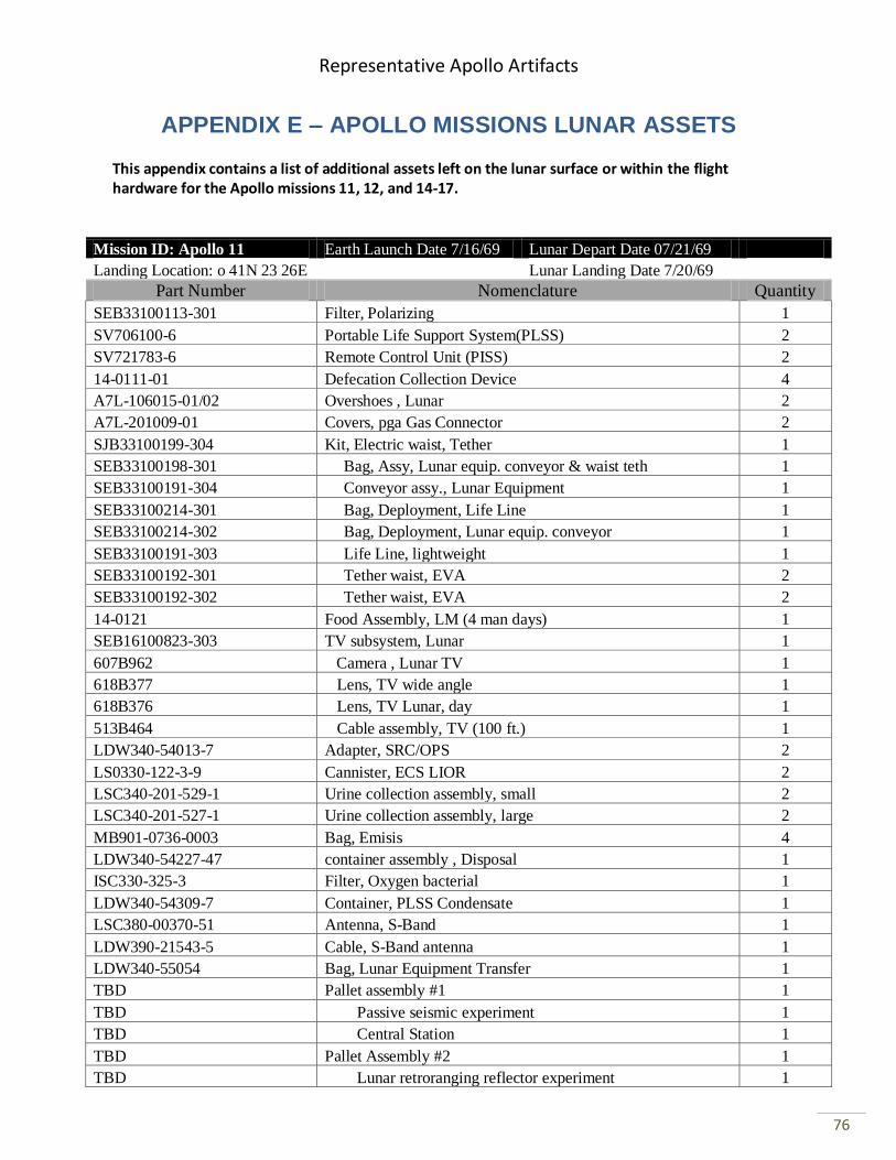
Representative Apollo Artifacts
76
APPENDIX E – APOLLO MISSIONS LUNAR ASSETS This appendix contains a list of additional assets left on the lunar surface or within the flight hardware for the Apollo missions 11, 12, and 14-17.
Mission ID: Apollo 11 Earth Launch Date 7/16/69 Lunar Depart Date 07/21/69
Landing Location: o 41N 23 26E Lunar Landing Date 7/20/69
Part Number Nomenclature Quantity
SEB33100113-301 Filter, Polarizing 1
SV706100-6 Portable Life Support System(PLSS) 2
SV721783-6 Remote Control Unit (PISS) 2
14-0111-01 Defecation Collection Device 4
A7L-106015-01/02 Overshoes , Lunar 2
A7L-201009-01 Covers, pga Gas Connector 2
SJB33100199-304 Kit, Electric waist, Tether 1
SEB33100198-301 Bag, Assy, Lunar equip. conveyor & waist teth 1
SEB33100191-304 Conveyor assy., Lunar Equipment 1
SEB33100214-301 Bag, Deployment, Life Line 1
SEB33100214-302 Bag, Deployment, Lunar equip. conveyor 1
SEB33100191-303 Life Line, lightweight 1
SEB33100192-301 Tether waist, EVA 2
SEB33100192-302 Tether waist, EVA 2
14-0121 Food Assembly, LM (4 man days) 1
SEB16100823-303 TV subsystem, Lunar 1
607B962 Camera , Lunar TV 1
618B377 Lens, TV wide angle 1
618B376 Lens, TV Lunar, day 1
513B464 Cable assembly, TV (100 ft.) 1
LDW340-54013-7 Adapter, SRC/OPS 2
LS0330-122-3-9 Cannister, ECS LIOR 2
LSC340-201-529-1 Urine collection assembly, small 2
LSC340-201-527-1 Urine collection assembly, large 2
MB901-0736-0003 Bag, Emisis 4
LDW340-54227-47 container assembly , Disposal 1
ISC330-325-3 Filter, Oxygen bacterial 1
LDW340-54309-7 Container, PLSS Condensate 1
LSC380-00370-51 Antenna, S-Band 1
LDW390-21543-5 Cable, S-Band antenna 1
LDW340-55054 Bag, Lunar Equipment Transfer 1
TBD Pallet assembly #1 1
TBD Passive seismic experiment 1
TBD Central Station 1
TBD Pallet Assembly #2 1
TBD Lunar retroranging reflector experiment 1
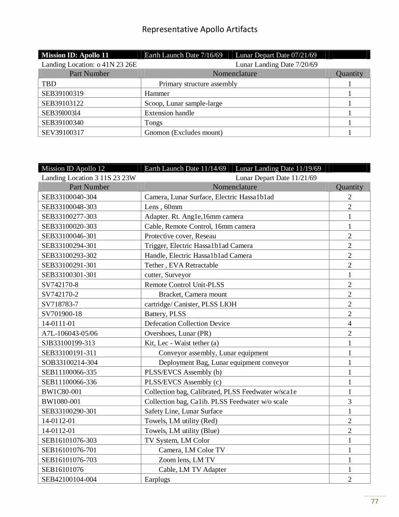
Representative Apollo Artifacts
77
Mission ID: Apollo 11 Earth Launch Date 7/16/69 Lunar Depart Date 07/21/69
Landing Location: o 41N 23 26E Lunar Landing Date 7/20/69
Part Number Nomenclature Quantity
TBD Primary structure assembly 1
SEB39100319 Hammer 1
SEB39103122 Scoop, Lunar sample-large 1
SEB39l003l4 Extension handle 1
SEB39100340 Tongs 1
SEV39100317 Gnomon (Excludes mount) 1
Mission ID Apollo 12 Earth Launch Date 11/14/69 Lunar Landing Date 11/19/69
Landing Location 3 11S 23 23W Lunar Depart Date 11/21/69
Part Number Nomenclature Quantity
SEB33100040-304 Camera, Lunar Surface, Electric Hassa1b1ad 2
SEB33100048-303 Lens , 60mm 2
SEB33100277-303 Adapter. Rt. Ang1e,16mm camera 1
SEB33100020-303 Cable, Remote Control, 16mm camera 1
SEB33100046-301 Protective cover, Reseau 2
SEB33100294-301 Trigger, Electric Hassa1b1ad Camera 2
SEB33100293-302 Handle, Electric Hassa1b1ad Camera 2
SEB33100291-301 Tether , EVA Retractable 2
SEB33100301-301 cutter, Surveyor 1
SV742170-8 Remote Control Unit-PLSS 2
SV742170-2 Bracket, Camera mount 2
SV718783-7 cartridge/ Canister, PLSS LIOH 2
SV701900-18 Battery, PLSS 2
14-0111-01 Defecation Collection Device 4
A7L-106043-05/06 Overshoes, Lunar (PR) 2
SJB33100199-313 Kit, Lec - Waist tether (a) 1
SEB33100191-311 Conveyor assembly, Lunar equipment 1
SOB33100214-304 Deployment Bag, Lunar equipment conveyor 1
SEB11100066-335 PLSS/EVCS Assembly (b) 1
SEB11100066-336 PLSS/EVCS Assembly (c) 1
BW1C80-001 Collection bag, Calibrated, PLSS Feedwater w/sca1e 1
BW1080-001 Collection bag, Ca1ib. PLSS Feedwater w/o scale 3
SEB33100290-301 Safety Line, Lunar Surface 1
14-0112-01 Towels, LM utility (Red) 2
14-0112-01 Towels, LM utility (Blue) 2
SEB16101076-303 TV System, LM Color 1
SEB16101076-701 Camera, LM Color TV 1
SEB16101076-703 Zoom lens, LM TV 1
SEB16101076 Cable, LM TV Adapter 1
SEB42100104-004 Earplugs 2
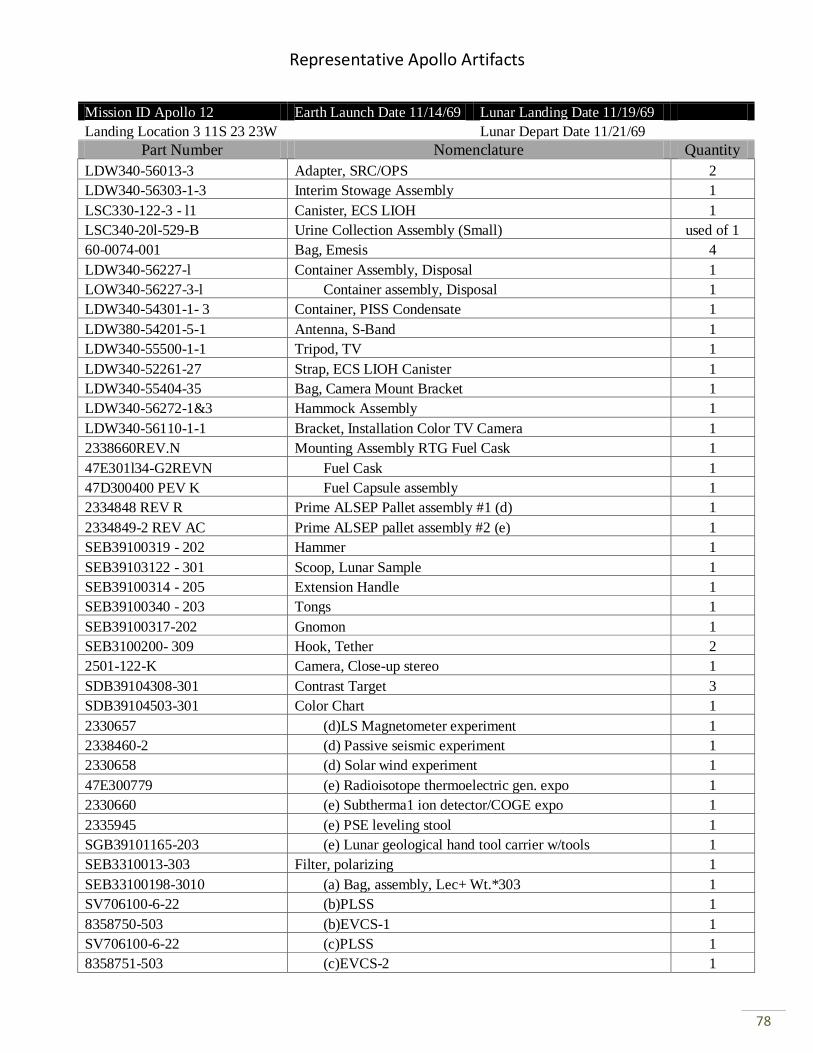
Representative Apollo Artifacts
78
Mission ID Apollo 12 Earth Launch Date 11/14/69 Lunar Landing Date 11/19/69
Landing Location 3 11S 23 23W Lunar Depart Date 11/21/69
Part Number Nomenclature Quantity
LDW340-56013-3 Adapter, SRC/OPS 2
LDW340-56303-1-3 Interim Stowage Assembly 1
LSC330-122-3 - l1 Canister, ECS LIOH 1
LSC340-20l-529-B Urine Collection Assembly (Small) used of 1
60-0074-001 Bag, Emesis 4
LDW340-56227-l Container Assembly, Disposal 1
LOW340-56227-3-l Container assembly, Disposal 1
LDW340-54301-1- 3 Container, PISS Condensate 1
LDW380-54201-5-1 Antenna, S-Band 1
LDW340-55500-1-1 Tripod, TV 1
LDW340-52261-27 Strap, ECS LIOH Canister 1
LDW340-55404-35 Bag, Camera Mount Bracket 1
LDW340-56272-1&3 Hammock Assembly 1
LDW340-56110-1-1 Bracket, Installation Color TV Camera 1
2338660REV.N Mounting Assembly RTG Fuel Cask 1
47E301l34-G2REVN Fuel Cask 1
47D300400 PEV K Fuel Capsule assembly 1
2334848 REV R Prime ALSEP Pallet assembly #1 (d) 1
2334849-2 REV AC Prime ALSEP pallet assembly #2 (e) 1
SEB39100319 - 202 Hammer 1
SEB39103122 - 301 Scoop, Lunar Sample 1
SEB39100314 - 205 Extension Handle 1
SEB39100340 - 203 Tongs 1
SEB39100317-202 Gnomon 1
SEB3100200- 309 Hook, Tether 2
2501-122-K Camera, Close-up stereo 1
SDB39104308-301 Contrast Target 3
SDB39104503-301 Color Chart 1
2330657 (d)LS Magnetometer experiment 1
2338460-2 (d) Passive seismic experiment 1
2330658 (d) Solar wind experiment 1
47E300779 (e) Radioisotope thermoelectric gen. expo 1
2330660 (e) Subtherma1 ion detector/COGE expo 1
2335945 (e) PSE leveling stool 1
SGB39101165-203 (e) Lunar geological hand tool carrier w/tools 1
SEB3310013-303 Filter, polarizing 1
SEB33100198-3010 (a) Bag, assembly, Lec+ Wt.*303 1
SV706100-6-22 (b)PLSS 1
8358750-503 (b)EVCS-1 1
SV706100-6-22 (c)PLSS 1
8358751-503 (c)EVCS-2 1
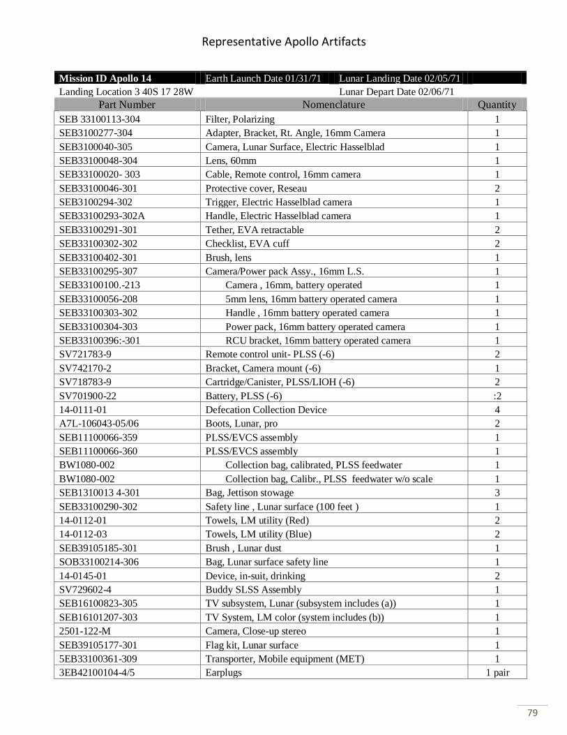
Representative Apollo Artifacts
79
Mission ID Apollo 14 Earth Launch Date 01/31/71 Lunar Landing Date 02/05/71
Landing Location 3 40S 17 28W Lunar Depart Date 02/06/71
Part Number Nomenclature Quantity
SEB 33100113-304 Filter, Polarizing 1
SEB3100277-304 Adapter, Bracket, Rt. Angle, 16mm Camera 1
SEB3100040-305 Camera, Lunar Surface, Electric Hasselblad 1
SEB33100048-304 Lens, 60mm 1
SEB33100020- 303 Cable, Remote control, 16mm camera 1
SEB33100046-301 Protective cover, Reseau 2
SEB3100294-302 Trigger, Electric Hasselblad camera 1
SEB33100293-302A Handle, Electric Hasselblad camera 1
SEB33100291-301 Tether, EVA retractable 2
SEB33100302-302 Checklist, EVA cuff 2
SEB33100402-301 Brush, lens 1
SEB33100295-307 Camera/Power pack Assy., 16mm L.S. 1
SEB33100100.-213 Camera , 16mm, battery operated 1
SEB33100056-208 5mm lens, 16mm battery operated camera 1
SEB33100303-302 Handle , 16mm battery operated camera 1
SEB33100304-303 Power pack, 16mm battery operated camera 1
SEB33100396:-301 RCU bracket, 16mm battery operated camera 1
SV721783-9 Remote control unit- PLSS (-6) 2
SV742170-2 Bracket, Camera mount (-6) 1
SV718783-9 Cartridge/Canister, PLSS/LIOH (-6) 2
SV701900-22 Battery, PLSS (-6) :2
14-0111-01 Defecation Collection Device 4
A7L-106043-05/06 Boots, Lunar, pro 2
SEB11100066-359 PLSS/EVCS assembly 1
SEB11100066-360 PLSS/EVCS assembly 1
BW1080-002 Collection bag, calibrated, PLSS feedwater 1
BW1080-002 Collection bag, Calibr., PLSS feedwater w/o scale 1
SEB1310013 4-301 Bag, Jettison stowage 3
SEB33100290-302 Safety line , Lunar surface (100 feet ) 1
14-0112-01 Towels, LM utility (Red) 2
14-0112-03 Towels, LM utility (Blue) 2
SEB39105185-301 Brush , Lunar dust 1
SOB33100214-306 Bag, Lunar surface safety line 1
14-0145-01 Device, in-suit, drinking 2
SV729602-4 Buddy SLSS Assembly 1
SEB16100823-305 TV subsystem, Lunar (subsystem includes (a)) 1
SEB16101207-303 TV System, LM color (system includes (b)) 1
2501-122-M Camera, Close-up stereo 1
SEB39105177-301 Flag kit, Lunar surface 1
5EB33100361-309 Transporter, Mobile equipment (MET) 1
3EB42100104-4/5 Earplugs 1 pair
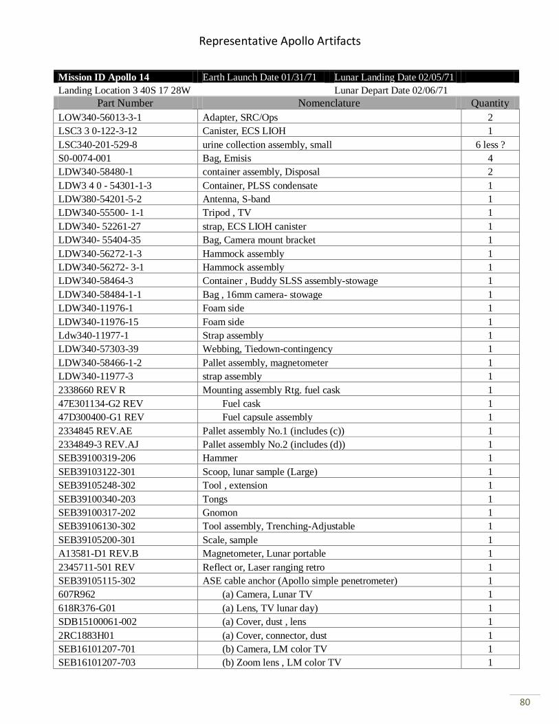
Representative Apollo Artifacts
80
Mission ID Apollo 14 Earth Launch Date 01/31/71 Lunar Landing Date 02/05/71
Landing Location 3 40S 17 28W Lunar Depart Date 02/06/71
Part Number Nomenclature Quantity
LOW340-56013-3-1 Adapter, SRC/Ops 2
LSC3 3 0-122-3-12 Canister, ECS LIOH 1
LSC340-201-529-8 urine collection assembly, small 6 less ?
S0-0074-001 Bag, Emisis 4
LDW340-58480-1 container assembly, Disposal 2
LDW3 4 0 - 54301-1-3 Container, PLSS condensate 1
LDW380-54201-5-2 Antenna, S-band 1
LDW340-55500- 1-1 Tripod , TV 1
LDW340- 52261-27 strap, ECS LIOH canister 1
LDW340- 55404-35 Bag, Camera mount bracket 1
LDW340-56272-1-3 Hammock assembly 1
LDW340-56272- 3-1 Hammock assembly 1
LDW340-58464-3 Container , Buddy SLSS assembly-stowage 1
LDW340-58484-1-1 Bag , 16mm camera- stowage 1
LDW340-11976-1 Foam side 1
LDW340-11976-15 Foam side 1
Ldw340-11977-1 Strap assembly 1
LDW340-57303-39 Webbing, Tiedown-contingency 1
LDW340-58466-1-2 Pallet assembly, magnetometer 1
LDW340-11977-3 strap assembly 1
2338660 REV R Mounting assembly Rtg. fuel cask 1
47E301134-G2 REV Fuel cask 1
47D300400-G1 REV Fuel capsule assembly 1
2334845 REV.AE Pallet assembly No.1 (includes (c)) 1
2334849-3 REV.AJ Pallet assembly No.2 (includes (d)) 1
SEB39100319-206 Hammer 1
SEB39103122-301 Scoop, lunar sample (Large) 1
SEB39105248-302 Tool , extension 1
SEB39100340-203 Tongs 1
SEB39100317-202 Gnomon 1
SEB39106130-302 Tool assembly, Trenching-Adjustable 1
SEB39105200-301 Scale, sample 1
A13581-D1 REV.B Magnetometer, Lunar portable 1
2345711-501 REV Reflect or, Laser ranging retro 1
SEB39105115-302 ASE cable anchor (Apollo simple penetrometer) 1
607R962 (a) Camera, Lunar TV 1
618R376-G01 (a) Lens, TV lunar day) 1
SDB15100061-002 (a) Cover, dust , lens 1
2RC1883H01 (a) Cover, connector, dust 1
SEB16101207-701 (b) Camera, LM color TV 1
SEB16101207-703 (b) Zoom lens , LM color TV 1
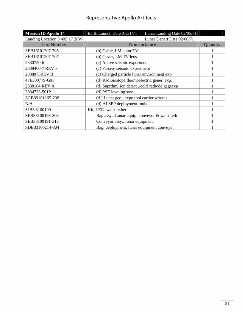
Representative Apollo Artifacts
81
Mission ID Apollo 14 Earth Launch Date 01/31/71 Lunar Landing Date 02/05/71
Landing Location 3 40S 17 28W Lunar Depart Date 02/06/71
Part Number Nomenclature Quantity
SEB16101207-705 (b) Cable, LM color TV 1
SEB16101207-707 (b) Cover, LM TV lens 1
2330750-6 (c) Active seismic experiment 1
2338460-7 REV F (c) Passive seismic experiment 1
2338975REV B (c) Charged particle lunar environment exp. 1
47E300779-G9F (d) Radioisotope thermoelectric gener. exp. 1
2338104 REV A (d) Suprthml ion detect ./cold cathode gageexp 1
2334723-501P (d) PSE leveling stool 1
SGB39101165-208 (d ) Lunar geol. expo tool carrier w/tools 1
N/A (d) ALSEP deployment tools 1
SJB3 3100199 Kit, LEC- waist tether 1
SEB33100198-303 Bag assy., Lunar equip. conveyor & waist teth 1
SEB33100191-313 Conveyor assy., lunar equipment 1
SDB33100214-304 Bag, deployment, lunar equipment conveyor 1
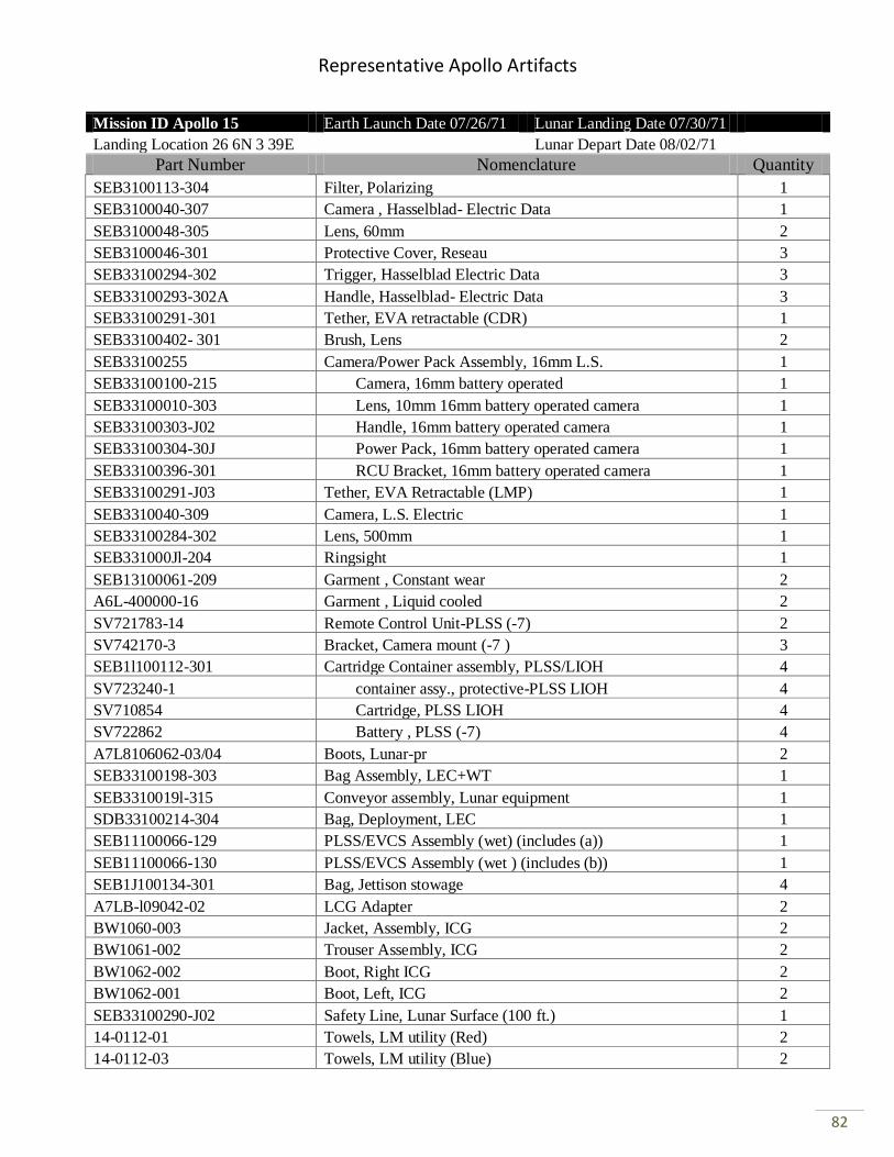
Representative Apollo Artifacts
82
Mission ID Apollo 15 Earth Launch Date 07/26/71 Lunar Landing Date 07/30/71
Landing Location 26 6N 3 39E Lunar Depart Date 08/02/71
Part Number Nomenclature Quantity
SEB3100113-304 Filter, Polarizing 1
SEB3100040-307 Camera , Hasselblad- Electric Data 1
SEB3100048-305 Lens, 60mm 2
SEB3100046-301 Protective Cover, Reseau 3
SEB33100294-302 Trigger, Hasselblad Electric Data 3
SEB33100293-302A Handle, Hasselblad- Electric Data 3
SEB33100291-301 Tether, EVA retractable (CDR) 1
SEB33100402- 301 Brush, Lens 2
SEB33100255 Camera/Power Pack Assembly, 16mm L.S. 1
SEB33100100-215 Camera, 16mm battery operated 1
SEB33100010-303 Lens, 10mm 16mm battery operated camera 1
SEB33100303-J02 Handle, 16mm battery operated camera 1
SEB33100304-30J Power Pack, 16mm battery operated camera 1
SEB33100396-301 RCU Bracket, 16mm battery operated camera 1
SEB33100291-J03 Tether, EVA Retractable (LMP) 1
SEB3310040-309 Camera, L.S. Electric 1
SEB33100284-302 Lens, 500mm 1
SEB331000Jl-204 Ringsight 1
SEB13100061-209 Garment , Constant wear 2
A6L-400000-16 Garment , Liquid cooled 2
SV721783-14 Remote Control Unit-PLSS (-7) 2
SV742170-3 Bracket, Camera mount (-7 ) 3
SEB1l100112-301 Cartridge Container assembly, PLSS/LIOH 4
SV723240-1 container assy., protective-PLSS LIOH 4
SV710854 Cartridge, PLSS LIOH 4
SV722862 Battery , PLSS (-7) 4
A7L8106062-03/04 Boots, Lunar-pr 2
SEB33100198-303 Bag Assembly, LEC+WT 1
SEB3310019l-315 Conveyor assembly, Lunar equipment 1
SDB33100214-304 Bag, Deployment, LEC 1
SEB11100066-129 PLSS/EVCS Assembly (wet) (includes (a)) 1
SEB11100066-130 PLSS/EVCS Assembly (wet ) (includes (b)) 1
SEB1J100134-301 Bag, Jettison stowage 4
A7LB-l09042-02 LCG Adapter 2
BW1060-003 Jacket, Assembly, ICG 2
BW1061-002 Trouser Assembly, ICG 2
BW1062-002 Boot, Right ICG 2
BW1062-001 Boot, Left, ICG 2
SEB33100290-J02 Safety Line, Lunar Surface (100 ft.) 1
14-0112-01 Towels, LM utility (Red) 2
14-0112-03 Towels, LM utility (Blue) 2
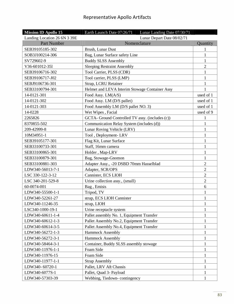
Representative Apollo Artifacts
83
Mission ID Apollo 15 Earth Launch Date 07/26/71 Lunar Landing Date 07/30/71
Landing Location 26 6N 3 39E Lunar Depart Date 08/02/71
Part Number Nomenclature Quantity
SEB39105185-302 Brush, Lunar Dust 1
SOB3J100214-306 Bag, Lunar Surface safety Line 1
SV729602-9 Buddy SLSS Assembly 1
V36-601012-35l Sleeping Restraint Assembly 2
SEB39106716-302 Tool Carrier, PLSS (CDR) 1
SEB39106717-J02 Tool carrier, PLSS (LMP) 1
SEBJ9106736-301 Strap, LCRU Retainer 1
SEB33100794-301 Helmet and LEVA Interim Stowage Container Assy 1
14-0121-301 Food Assy. LM(A/S) used of 1
14-0121-302 Food Assy. LM (D/S pallet) used of 1
14-0121-303 Food Assembly LM (D/S pallet NO. 3) used of 1
14-0228 Wet Wipes , Facial used of 9
2265826 GCTA- Ground Controlled TV assy. (includes (c)) 1
8370855-502 Communication Relay System (includes (d)) 1
209-42999-8 Lunar Roving Vehicle (LRV) 1
10M34951-1 Tool , Deployment- LRV 1
SEB39105177-301 Flag Kit, Lunar Surface 1
SEB33100733-301 Staff, 16mm camera 1
SEB33100865-301 Holder , Map-LRV 1
SEB33100879-301 Bag, Stowage-Gnomon 1
SEB33100881-303 Adapter Assy., -20 DSBD 70mm Hasselblad 2
LDW340-56013-7-1 Adapter, SCR/OPS 2
LSC 330-122-3-12 Cannister, ECS LIOH 2
LSC 340-201-529-8 Urine collection assy., (small) 2
60-0074-001 Bag , Emisis 6
LDW340-55500-1-1 Tripod, TV 1
LDW340-52261-27 strap, ECS LIOH Cannister 1
LDW340-11246-35 strap, LIOH 1
LSC340-1000-19-1 Urine receptacle system 1
LDW340-60611-1-4 Pallet assembly No. 1, Equipment Transfer 1
LDW340-60612-1-3 Pallet Assembly No.2, Equipment Transfer 1
LDW340-60614-3-5 Pallet Assembly No.4, Equipment Transfer 1
LDW340-56272-1-3 Hammock Assembly 1
LDW340-56272-3-1 Hammock Assembly 1
LDW340-58464-3-1 Container, Buddy SLSS assembly stowage 1
LDW340-11976-1-1 Foam Side 1
LDW340-11976-15 Foam Side 1
LDW340-11977-1-1 Strap Assembly 1
LDW340- 60720-1 Pallet, LRV Aft Chassis 1
LDW340-6077S-1 Pallet, Quad 3- Payload 1
LDW340-57303-39 Webbing, Tiedown- contingency 1
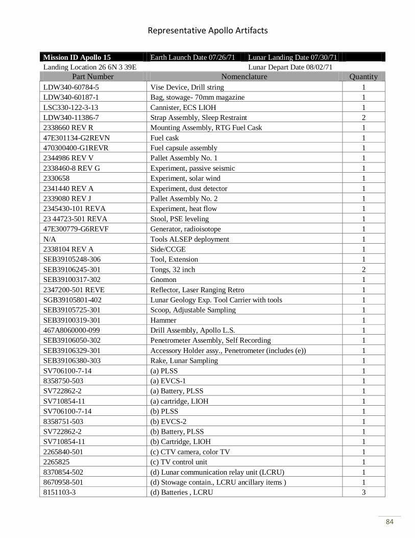
Representative Apollo Artifacts
84
Mission ID Apollo 15 Earth Launch Date 07/26/71 Lunar Landing Date 07/30/71
Landing Location 26 6N 3 39E Lunar Depart Date 08/02/71
Part Number Nomenclature Quantity
LDW340-60784-5 Vise Device, Drill string 1
LDW340-60187-1 Bag, stowage- 70mm magazine 1
LSC330-122-3-13 Cannister, ECS LIOH 1
LDW340-11386-7 Strap Assembly, Sleep Restraint 2
2338660 REV R Mounting Assembly, RTG Fuel Cask 1
47E301134-G2REVN Fuel cask 1
470300400-G1REVR Fuel capsule assembly 1
2344986 REV V Pallet Assembly No. 1 1
2338460-8 REV G Experiment, passive seismic 1
2330658 Experiment, solar wind 1
2341440 REV A Experiment, dust detector 1
2339080 REV J Pallet Assembly No. 2 1
2345430-101 REVA Experiment, heat flow 1
23 44723-501 REVA Stool, PSE leveling 1
47E300779-G6REVF Generator, radioisotope 1
N/A Tools ALSEP deployment 1
2338104 REV A Side/CCGE 1
SEB39105248-306 Tool, Extension 1
SEB39106245-301 Tongs, 32 inch 2
SEB39100317-302 Gnomon 1
2347200-501 REVE Reflector, Laser Ranging Retro 1
SGB39105801-402 Lunar Geology Exp. Tool Carrier with tools 1
SEB39105725-301 Scoop, Adjustable Sampling 1
SEB39100319-301 Hammer 1
467A8060000-099 Drill Assembly, Apollo L.S. 1
SEB39106050-302 Penetrometer Assembly, Self Recording 1
SEB39106329-301 Accessory Holder assy., Penetrometer (includes (e)) 1
SEB39106380-303 Rake, Lunar Sampling 1
SV706100-7-14 (a) PLSS 1
8358750-503 (a) EVCS-1 1
SV722862-2 (a) Battery, PLSS 1
SV710854-11 (a) cartridge, LIOH 1
SV706100-7-14 (b) PLSS 1
8358751-503 (b) EVCS-2 1
SV722862-2 (b) Battery, PLSS 1
SV710854-11 (b) Cartridge, LIOH 1
2265840-501 (c) CTV camera, color TV 1
2265825 (c) TV control unit 1
8370854-502 (d) Lunar communication relay unit (LCRU) 1
8670958-501 (d) Stowage contain., LCRU ancillary items ) 1
8151103-3 (d) Batteries , LCRU 3
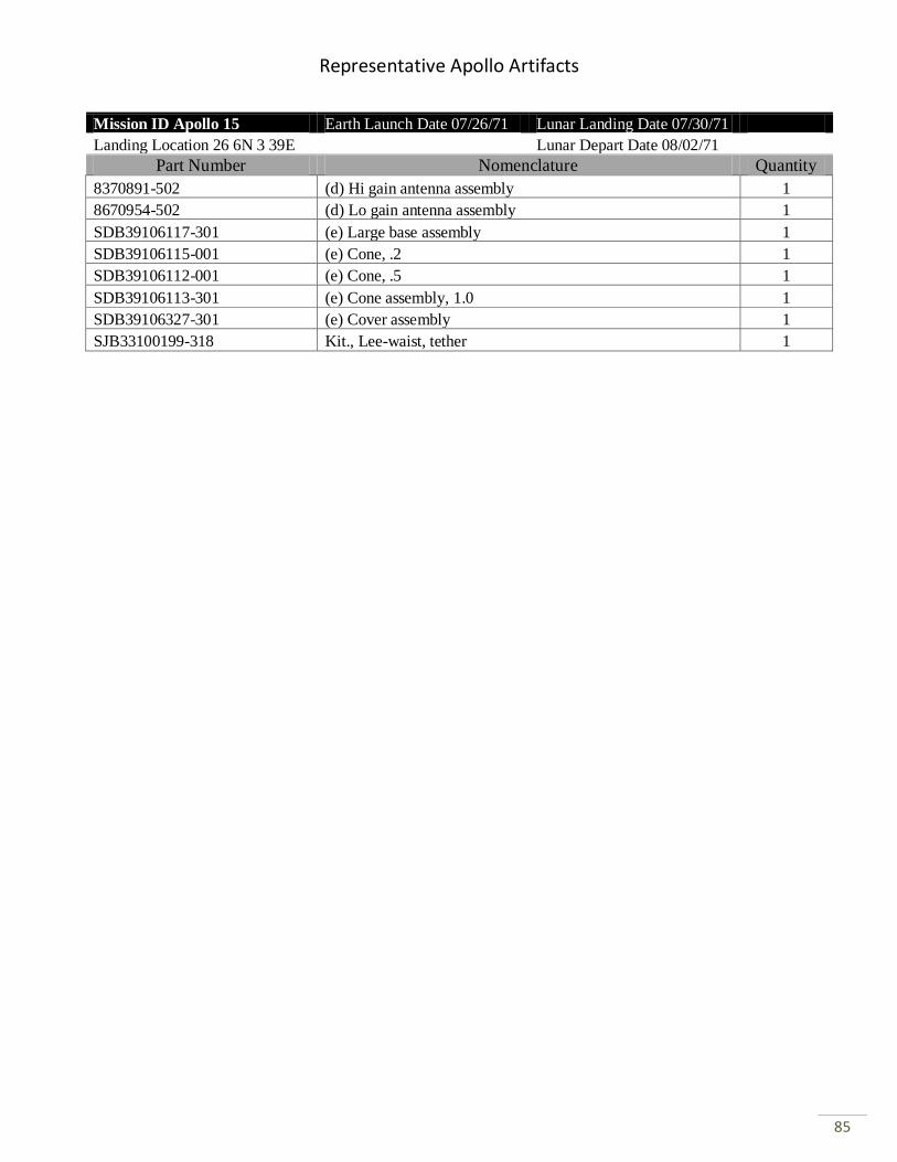
Representative Apollo Artifacts
85
Mission ID Apollo 15 Earth Launch Date 07/26/71 Lunar Landing Date 07/30/71
Landing Location 26 6N 3 39E Lunar Depart Date 08/02/71
Part Number Nomenclature Quantity
8370891-502 (d) Hi gain antenna assembly 1
8670954-502 (d) Lo gain antenna assembly 1
SDB39106117-301 (e) Large base assembly 1
SDB39106115-001 (e) Cone, .2 1
SDB39106112-001 (e) Cone, .5 1
SDB39106113-301 (e) Cone assembly, 1.0 1
SDB39106327-301 (e) Cover assembly 1
SJB33100199-318 Kit., Lee-waist, tether 1
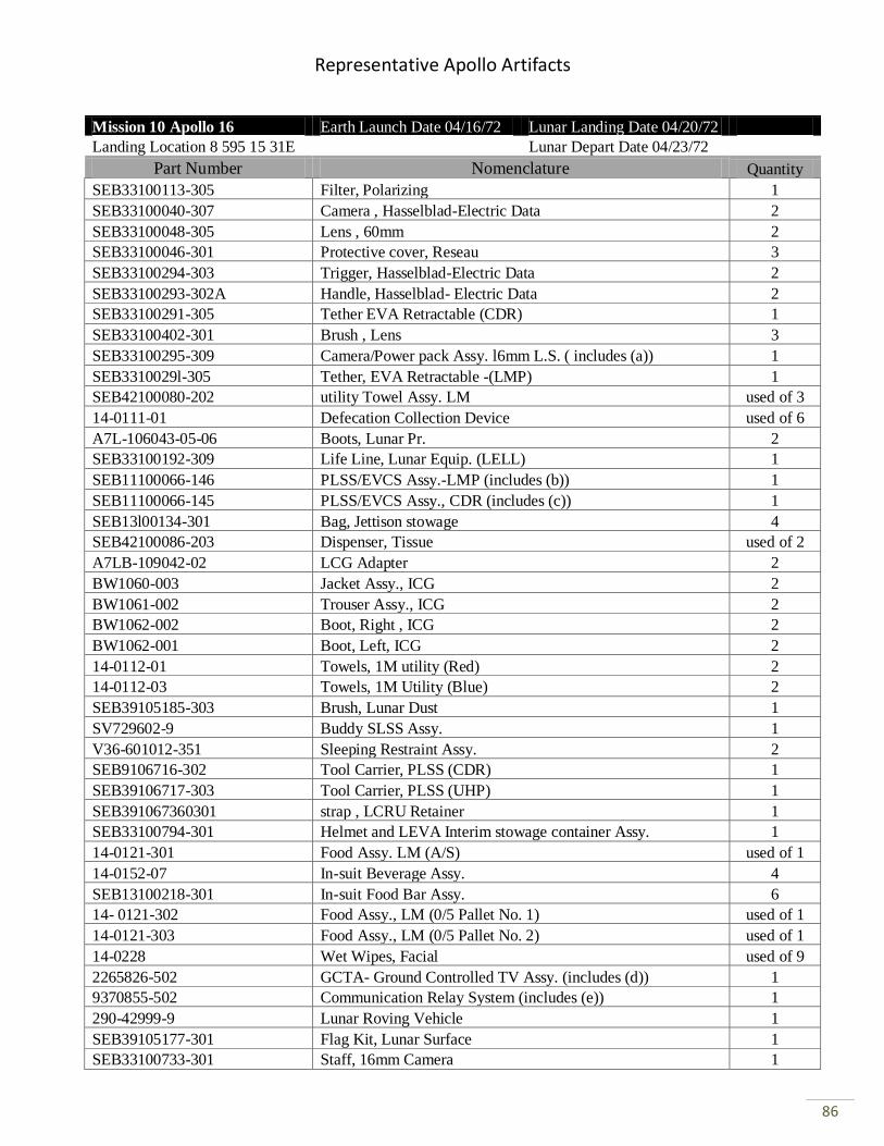
Representative Apollo Artifacts
86
Mission 10 Apollo 16 Earth Launch Date 04/16/72 Lunar Landing Date 04/20/72
Landing Location 8 595 15 31E Lunar Depart Date 04/23/72
Part Number Nomenclature Quantity
SEB33100113-305 Filter, Polarizing 1
SEB33100040-307 Camera , Hasselblad-Electric Data 2
SEB33100048-305 Lens , 60mm 2
SEB33100046-301 Protective cover, Reseau 3
SEB33100294-303 Trigger, Hasselblad-Electric Data 2
SEB33100293-302A Handle, Hasselblad- Electric Data 2
SEB33100291-305 Tether EVA Retractable (CDR) 1
SEB33100402-301 Brush , Lens 3
SEB33100295-309 Camera/Power pack Assy. l6mm L.S. ( includes (a)) 1
SEB3310029l-305 Tether, EVA Retractable -(LMP) 1
SEB42100080-202 utility Towel Assy. LM used of 3
14-0111-01 Defecation Collection Device used of 6
A7L-106043-05-06 Boots, Lunar Pr. 2
SEB33100192-309 Life Line, Lunar Equip. (LELL) 1
SEB11100066-146 PLSS/EVCS Assy.-LMP (includes (b)) 1
SEB11100066-145 PLSS/EVCS Assy., CDR (includes (c)) 1
SEB13l00134-301 Bag, Jettison stowage 4
SEB42100086-203 Dispenser, Tissue used of 2
A7LB-109042-02 LCG Adapter 2
BW1060-003 Jacket Assy., ICG 2
BW1061-002 Trouser Assy., ICG 2
BW1062-002 Boot, Right , ICG 2
BW1062-001 Boot, Left, ICG 2
14-0112-01 Towels, 1M utility (Red) 2
14-0112-03 Towels, 1M Utility (Blue) 2
SEB39105185-303 Brush, Lunar Dust 1
SV729602-9 Buddy SLSS Assy. 1
V36-601012-351 Sleeping Restraint Assy. 2
SEB9106716-302 Tool Carrier, PLSS (CDR) 1
SEB39106717-303 Tool Carrier, PLSS (UHP) 1
SEB391067360301 strap , LCRU Retainer 1
SEB33100794-301 Helmet and LEVA Interim stowage container Assy. 1
14-0121-301 Food Assy. LM (A/S) used of 1
14-0152-07 In-suit Beverage Assy. 4
SEB13100218-301 In-suit Food Bar Assy. 6
14- 0121-302 Food Assy., LM (0/5 Pallet No. 1) used of 1
14-0121-303 Food Assy., LM (0/5 Pallet No. 2) used of 1
14-0228 Wet Wipes, Facial used of 9
2265826-502 GCTA- Ground Controlled TV Assy. (includes (d)) 1
9370855-502 Communication Relay System (includes (e)) 1
290-42999-9 Lunar Roving Vehicle 1
SEB39105177-301 Flag Kit, Lunar Surface 1
SEB33100733-301 Staff, 16mm Camera 1

Representative Apollo Artifacts
87
Mission 10 Apollo 16 Earth Launch Date 04/16/72 Lunar Landing Date 04/20/72
Landing Location 8 595 15 31E Lunar Depart Date 04/23/72
Part Number Nomenclature Quantity
SEB33100865-303 Holder, Map LRV 1
SEB33100881-303* Adapter Assy., 20 DSBD 70mm Hasselblad, *- 303B 1
SEB33100897-301 Staff Loop Assy., l6mm Camera 1
SEB33100897-303 Staff Loop Assy., Low Gain 1
SEB3310092-301 Sunshade, GCTA 1
LDW340-56013-3-3 Adapter, SRC/Ops 2
LS0330-122-3-12 Canister, ECS LIOH 1
LSC340-201-529-8 Urine Collection Assy. (Small) used of 2
60-0074-001 Bag, Emesis used of 6
LDW340-60636-1 Bag, Equipt. Transfer 1
LDW340-55s00-1-1 Tripod, TV 1
LDW340-s2261-27 strap, ECS LIOH Canister 1
LDW340-11246-3s strap LIOH 1
LSC340-1000-19-2 Urine, Receptacle system 1
LDW340-60611-1-s Pallet Assy. No. 1, Equipment Transfer 1
LDW340-60612-1-3 Pallet Assy. No. 2, Equipment Transfer 1
LDW340-60614-3-4 Pallet Assy. No. 4, Equipment Transfer 1
LDW340-56272-1-3 Hammock Assy. 1
LDW340-s6272-3-1 Hammock Assy. 1
LDW340-s8464-3-1 Container, Buddy SLSS Assy., stowage 1
LDW340-60781-1 Pallet, LRV Aft Chassis 1
LDW340-60780-3-1 Pallet, Quad 3- Payload 1
LDW340-s7303-39 Webbing, Tie-down contingency 1
LDW340-60784-5-3 Vise Device, Drill string 1
LDW340-60187-s Bag, stowage. 500mm system 1
LSC330-122-3-13 Canister, ECS LIOH 1
LDW340-11366-7 strap Assy., Sleep Restraint 2
LDW340-6066s-1 container, Bore/core stem stowage 1
LDW340-6066s-9-1 cover, Bore/Core Stem stowage 1
LDW340-60666-s Retainer Assy., Lower 1
LDW340-60666-7 Retainer Assy., Upper 1
LDW340-P15677-1 Cover Assy., Retainer 1
LDW340M15913-13 Spacer (Bore and Core Stem Stowage) 1
LDW340M15913 -11 Spacer (Bore and Core Stem Stowage) 1
LDW340-P15924-13 stowage Retainer, GCTA Sunshade 1
LDW340-60668-9-1 Stowage strap Assy., GCTA Sunshade 1
2238660 REV R Mounting Assy., Rtg. Fuel Cask 1
47E301134-G2REVN Fuel Cask 1
47D300400-G1REV Fuel Capsule Assy. 1
2339000 REV AB Pallet Assy. No. 1 (includes (f)) 1
2339100 REV AD Pallet Assy. No. 2 (includes (g)) 1
SEB39105248-308 Tool Extension 2
SEB39106245-301 Tongs, 32 inch 2
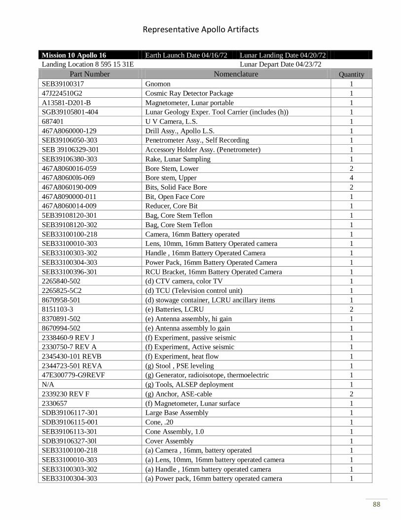
Representative Apollo Artifacts
88
Mission 10 Apollo 16 Earth Launch Date 04/16/72 Lunar Landing Date 04/20/72
Landing Location 8 595 15 31E Lunar Depart Date 04/23/72
Part Number Nomenclature Quantity
SEB39100317 Gnomon 1
47J224510G2 Cosmic Ray Detector Package 1
A13581-D201-B Magnetometer, Lunar portable 1
SGB39105801-404 Lunar Geology Exper. Tool Carrier (includes (h)) 1
687401 U V Camera, L.S. 1
467A8060000-129 Drill Assy., Apollo L.S. 1
SEB39106050-303 Penetrometer Assy., Self Recording 1
SEB 39106329-301 Accessory Holder Assy. (Penetrometer) 1
SEB39106380-303 Rake, Lunar Sampling 1
467A8060016-059 Bore Stem, Lower 2
467A80600l6-069 Bore stem, Upper 4
467A8060190-009 Bits, Solid Face Bore 2
467A8090000-011 Bit, Open Face Core 1
467A8060014-009 Reducer, Core Bit 1
5EB39108120-301 Bag, Core Stem Teflon 1
SEB39108120-302 Bag, Core Stem Teflon 1
SEB33100100-218 Camera, 16mm Battery operated 1
SEB33100010-303 Lens, 10mm, 16mm Battery Operated camera 1
SEB33100303-302 Handle , 16mm Battery Operated Camera 1
SEB33100304-303 Power Pack, 16mm Battery Operated Camera 1
SEB33100396-301 RCU Bracket, 16mm Battery Operated Camera 1
2265840-502 (d) CTV camera, color TV 1
2265825-5C2 (d) TCU (Television control unit) 1
8670958-501 (d) stowage container, LCRU ancillary items 1
8151103-3 (e) Batteries, LCRU 2
8370891-502 (e) Antenna assembly, hi gain 1
8670994-502 (e) Antenna assembly lo gain 1
2338460-9 REV J (f) Experiment, passive seismic 1
2330750-7 REV A (f) Experiment, Active seismic 1
2345430-101 REVB (f) Experiment, heat flow 1
2344723-501 REVA (g) Stool , PSE leveling 1
47E300779-G9REVF (g) Generator, radioisotope, thermoelectric 1
N/A (g) Tools, ALSEP deployment 1
2339230 REV F (g) Anchor, ASE-cable 2
2330657 (f) Magnetometer, Lunar surface 1
SDB39106117-301 Large Base Assembly 1
SDB39106115-001 Cone, .20 1
SEB39106113-301 Cone Assembly, 1.0 1
SDB39106327-30l Cover Assembly 1
SEB33100100-218 (a) Camera , 16mm, battery operated 1
SEB33100010-303 (a) Lens, 10mm, 16mm battery operated camera 1
SEB33100303-302 (a) Handle , 16mm battery operated camera 1
SEB33100304-303 (a) Power pack, 16mm battery operated camera 1
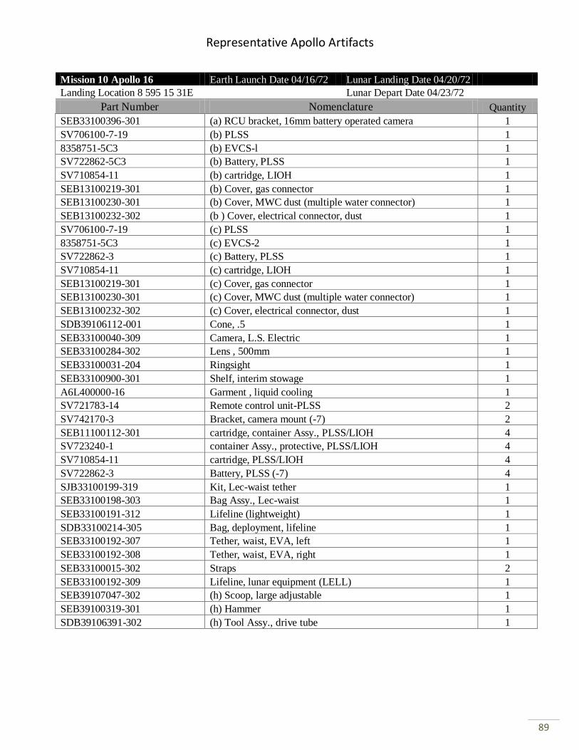
Representative Apollo Artifacts
89
Mission 10 Apollo 16 Earth Launch Date 04/16/72 Lunar Landing Date 04/20/72
Landing Location 8 595 15 31E Lunar Depart Date 04/23/72
Part Number Nomenclature Quantity
SEB33100396-301 (a) RCU bracket, 16mm battery operated camera 1
SV706100-7-19 (b) PLSS 1
8358751-5C3 (b) EVCS-l 1
SV722862-5C3 (b) Battery, PLSS 1
SV710854-11 (b) cartridge, LIOH 1
SEB13100219-301 (b) Cover, gas connector 1
SEB13100230-301 (b) Cover, MWC dust (multiple water connector) 1
SEB13100232-302 (b ) Cover, electrical connector, dust 1
SV706100-7-19 (c) PLSS 1
8358751-5C3 (c) EVCS-2 1
SV722862-3 (c) Battery, PLSS 1
SV710854-11 (c) cartridge, LIOH 1
SEB13100219-301 (c) Cover, gas connector 1
SEB13100230-301 (c) Cover, MWC dust (multiple water connector) 1
SEB13100232-302 (c) Cover, electrical connector, dust 1
SDB39106112-001 Cone, .5 1
SEB33100040-309 Camera, L.S. Electric 1
SEB33100284-302 Lens , 500mm 1
SEB33100031-204 Ringsight 1
SEB33100900-301 Shelf, interim stowage 1
A6L400000-16 Garment , liquid cooling 1
SV721783-14 Remote control unit-PLSS 2
SV742170-3 Bracket, camera mount (-7) 2
SEB11100112-301 cartridge, container Assy., PLSS/LIOH 4
SV723240-1 container Assy., protective, PLSS/LIOH 4
SV710854-11 cartridge, PLSS/LIOH 4
SV722862-3 Battery, PLSS (-7) 4
SJB33100199-319 Kit, Lec-waist tether 1
SEB33100198-303 Bag Assy., Lec-waist 1
SEB33100191-312 Lifeline (lightweight) 1
SDB33100214-305 Bag, deployment, lifeline 1
SEB33100192-307 Tether, waist, EVA, left 1
SEB33100192-308 Tether, waist, EVA, right 1
SEB33100015-302 Straps 2
SEB33100192-309 Lifeline, lunar equipment (LELL) 1
SEB39107047-302 (h) Scoop, large adjustable 1
SEB39100319-301 (h) Hammer 1
SDB39106391-302 (h) Tool Assy., drive tube 1
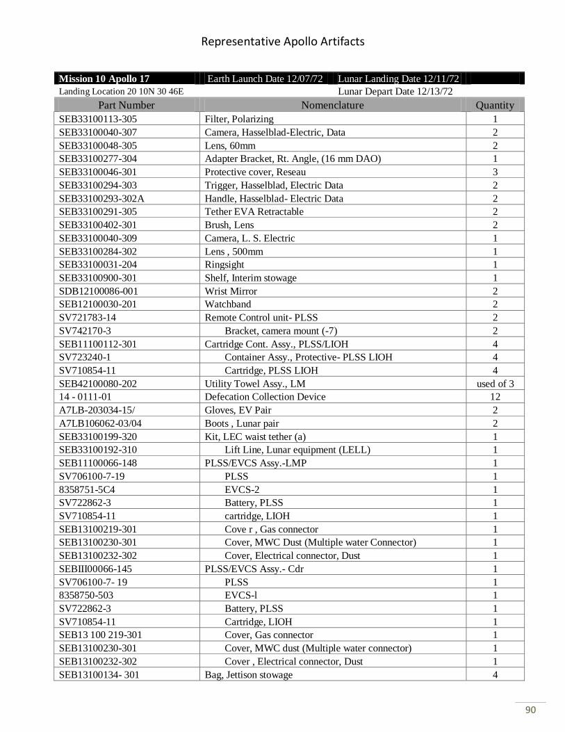
Representative Apollo Artifacts
90
Mission 10 Apollo 17 Earth Launch Date 12/07/72 Lunar Landing Date 12/11/72
Landing Location 20 10N 30 46E Lunar Depart Date 12/13/72
Part Number Nomenclature Quantity
SEB33100113-305 Filter, Polarizing 1
SEB33100040-307 Camera, Hasselblad-Electric, Data 2
SEB33100048-305 Lens, 60mm 2
SEB33100277-304 Adapter Bracket, Rt. Angle, (16 mm DAO) 1
SEB33100046-301 Protective cover, Reseau 3
SEB33100294-303 Trigger, Hasselblad, Electric Data 2
SEB33100293-302A Handle, Hasselblad- Electric Data 2
SEB33100291-305 Tether EVA Retractable 2
SEB33100402-301 Brush, Lens 2
SEB33100040-309 Camera, L. S. Electric 1
SEB33100284-302 Lens , 500mm 1
SEB33100031-204 Ringsight 1
SEB33100900-301 Shelf, Interim stowage 1
SDB12100086-001 Wrist Mirror 2
SEB12100030-201 Watchband 2
SV721783-14 Remote Control unit- PLSS 2
SV742170-3 Bracket, camera mount (-7) 2
SEB11100112-301 Cartridge Cont. Assy., PLSS/LIOH 4
SV723240-1 Container Assy., Protective- PLSS LIOH 4
SV710854-11 Cartridge, PLSS LIOH 4
SEB42100080-202 Utility Towel Assy., LM used of 3
14 - 0111-01 Defecation Collection Device 12
A7LB-203034-15/ Gloves, EV Pair 2
A7LB106062-03/04 Boots , Lunar pair 2
SEB33100199-320 Kit, LEC waist tether (a) 1
SEB33100192-310 Lift Line, Lunar equipment (LELL) 1
SEB11100066-148 PLSS/EVCS Assy.-LMP 1
SV706100-7-19 PLSS 1
8358751-5C4 EVCS-2 1
SV722862-3 Battery, PLSS 1
SV710854-11 cartridge, LIOH 1
SEB13100219-301 Cove r , Gas connector 1
SEB13100230-301 Cover, MWC Dust (Multiple water Connector) 1
SEB13100232-302 Cover, Electrical connector, Dust 1
SEBIII00066-145 PLSS/EVCS Assy.- Cdr 1
SV706100-7- 19 PLSS 1
8358750-503 EVCS-l 1
SV722862-3 Battery, PLSS 1
SV710854-11 Cartridge, LIOH 1
SEB13 100 219-301 Cover, Gas connector 1
SEB13100230-301 Cover, MWC dust (Multiple water connector) 1
SEB13100232-302 Cover , Electrical connector, Dust 1
SEB13100134- 301 Bag, Jettison stowage 4

Representative Apollo Artifacts
91
Mission 10 Apollo 17 Earth Launch Date 12/07/72 Lunar Landing Date 12/11/72
Landing Location 20 10N 30 46E Lunar Depart Date 12/13/72
Part Number Nomenclature Quantity
SEB42100086-203 Dispenser, Tissue 2
A7LB-109042-02 LCG Adapter 2
BWI 060-003 Jacket Assy., ICG 2
BW1061-002 Trouser Assy., ICG 2
BWI 062-002 Boot, right l CG 2
BW1062-001 Boot, left ICG 2
14-0112-01 Towels, LM, Utility (Red) 2
14-0112-03 Towels , UK Utility (Blue) 2
SEB39105185-303 Brush, Lunar Dust 1
14-0151-02 Device, I n-suit, Drinking 4
SV729602-9 Buddy, SLSS Assy. 1
V36-601012-351 Sleeping Restraint Assy. 2
SEB391067°16- 303 Tool carrier, PLSS (Cdr) 1
SEB39106717-303 Tool Carrier, PLSS (LMP) 1
SEB39106736-301 strap, LCRU Retainer 1
SEB33100794-301 Hel met and LEVA interim stowage container assembly 1
SV748660-1 Antenna Repair Kit, Ops 1
A7L-101033-02 Lanyard, IV ITLSA Donning 1
SEC12100087-301 Bag, LM Personal Hygiene Kit 1
N/A Nail Clippers 1
N/A Soap 1
14-0121-301 Food Assy., LM(A/S) used of 1
14-0121-302 Food Assy., LM (D/S Pallet No. 1) used of 1
14-0228 Wet Wipes, Facial used of 9
1F218 Ointment, Mycolog Bact. 1
2265826-502 GCTA-Ground controlled television assembly 1
2265840-502 CTV-Camera, color TV 1
2265825-502 TCU-Television control unit 1
2265261-502 Stowage mount Assy., TV camera 1
8370855-502 communication relay system 1
8370854-502 LCRU, (Lunar communications relay unit) 1
8670958-501 Stowage container; LCRU ancillary items 1
8151103-3 Batteries , LCRU 2
8370891-502 Antenna Assy., Hi-gain 1
8670994-502 Antenna Assy., Lo-gain 1
2275697-501 Helper spring Assy., TCU cradle 1
209-42999-10 Lunar Roving Vehicle 1
SEB39105177-301 Flag kit, Lunar surface 1
SEB33100881-305 Adapter Assy., 20 DSBD 70mm Hasselblad 2
SEB33l00897-303 Staff Loop Assy. Lo-gain 1
SEB33100902-307 Sun Shade, GCTA 1
SEB331009l1-303 Staff Assy., LRV accessory 1
SEB33100918-301 Hap holder adapter, loop Assy. 1
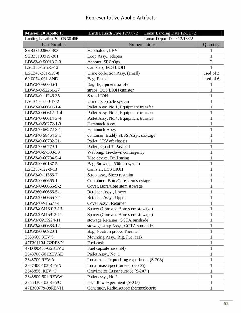
Representative Apollo Artifacts
92
Mission 10 Apollo 17 Earth Launch Date 12/07/72 Lunar Landing Date 12/11/72
Landing Location 20 10N 30 46E Lunar Depart Date 12/13/72
Part Number Nomenclature Quantity
SEB33100865-303 Hap holder, LRV 1
SEB33100919-301 Loop Assy., adapter 1
LDW340-56013-3-3 Adapter, SRC/Ops 2
LSC330-12 2-3-12 Canisters, ECS LIOH 1
LSC340-201-529-8 Urine collection Assy. (small) used of 2
60-0074-001 AND Bag, Emisis used of 6
LDW340-60636-1 Bag, Equipment transfer 1
LDW340-52261-27 straps, ECS LIOH canister 1
LDW340-11246-35 Strap LIOH 1
LSC340-1000-19-2 Urine receptacle system 1
LDW340-60611-1-6 Pallet Assy. No.1, Equipment transfer 1
LDW340-60612 -1-4 Pallet Assy. No.2, Equipment transfer 1
LDW340-60614-3-4 Pallet Assy. No.4, Equipment transfer 1
LDW340-56272-1-3 Hammock Assy. 1
LDW340-56272-3-1 Hammock Assy. 1
LDW340-58464-3-1 container, Buddy SLSS Assy., stowage 1
LDW340-60782-21- Pallet, LRV aft chassis 1
LDW340-60779-1 Pallet , Quad 3- Payload 1
LDW340-57303-39 Webbing, Tie-down contingency 1
LDW340-60784-5-4 Vise device, Drill string 1
LDW340-60187-5 Bag, Stowage, 500mm system 1
LSC330-122-3-13 Canister, ECS LIOH 1
LDW340-11366-7 Strap assy., Sleep restraint 1
LDW340-60665-1 Container , Bore/Core stem stowage 1
LDW340-60665-9-2 Cover, Bore/Core stem stowage 1
LDW360-60666-5-1 Retainer Assy., Lower 1
LDW340-60666-7-1 Retainer Assy., Upper 1
LDW340P-15677-1 Cover Assy., Retainer 1
LDW340M15913-13- Spacer (Core and Bore stem stowage) 1
LDW340M15913-11- Spacer (Core and Bore stem stowage) 1
LDW340P15924-11 stowage Retainer, GCTA sunshade 1
LDW340-60668-1-1 stowage strap Assy., GCTA sunshade 1
LDW280-60820-1 Bag, Neutron probe, Thermal 1
2338660 REV S Mounting Assy., Rig. Fuel cask 1
47E301134-G2REVN Fuel cask 1
47D300400-G2REVU Fuel capsule assembly 1
2348700-501REVAE Pallet Assy., No. 1 1
2348700 REV A Lunar seismic profiling experiment (S-203) 1
2347400-103 REVN Lunar mass spectrometer (S-205) 1
2345856, REV. C Gravimeter, Lunar surface (S-207 ) 1
2348800-501 REVW Pallet assy., No.2 1
2345430-102 REVC Heat flow experiment (S-037) 1
47E300779-09REVH Generator, Radioisotope thermoelectric 1
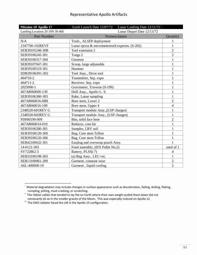
Representative Apollo Artifacts
93
Mission 10 Apollo 17 Earth Launch Date 12/07/72 Lunar Landing Date 12/11/72
Landing Location 20 10N 30 46E Lunar Depart Date 12/13/72
Part Number Nomenclature Quantity
N/A Tools , ALSEP deployment 1
2347700-102REVF Lunar ejecta & micrometeoroid experim. (S-202) 1
SEB39105248-30B Tool extension 2 2
SEB39106245-301 Tongs 2 2
SEB39100317-304 Gnomon 1
SEB39107047-301 Scoop, large adjustable 1
SEB39100319-301 Hammer 1
SDB39106391-302 Tool Assy., Drive tool 1
464710-2 Transmitter, Sep. expo 1
464711-2 Receiver, Sep. expo 1
2025000-1 Gravimeter, Traverse (S-199) 1
467A8060000-139 Drill Assy., Apollo L. S. 1
SEB39106380-303 Rake, Lunar sampling 1
467A8060016-0B9 Bore stem, Lower 2 2
467A8060016-109 Bore stem, Upper 4 4
2348320-601REV G Transport module Assy.,(LSP charges) 1
2348320-602REV G Transport module Assy., (LSP charges) 1
PD000190-009 Bits, solid face bore 2
467A8060014-019 Reducer, core bit 1
SEB39106280-301 Sampler, LRV soil 1
SEB39108120-30S Bag, Core stem Teflon 1
SEB39108120-306 Bag, Core stem Teflon 1
SEB42100632-301 Earplug and overwrap pouch Assy. 1
14-0121-303 Food assembly, (D/S Pallet No.2) used of 1
SV722862-3 Battery, PLSS(-7) 4
SEB33100198-303 (a) Bag Assy., LEC+wt. 1
SEB13100061-209 Garment, constant wear 2
A6L-400000-19 Garment , liquid cooling 2
i Material degradation may include changes in surface appearance such as discoloration, fading, dulling, flaking,
rumpling, pitting, mud-cracking, or scratching. ii The ribbon cables that tended to lay flat on Earth where their own weight pulled them down did not
necessarily do so in the smaller gravity of the Moon. This was especially noticed on Apollo 12. iii The SWS radiator faced the LM in the Apollo 15 configuration.