national radio astronomy observatory · national radio astronomy observatory ... of the cafs...
TRANSCRIPT

NATIONAL RADIO ASTRONOMY OBSERVATORY POST OFFICE BOX 2 GREEN BANK, WEST VIRGINIA 24944-0002 TELEPHONE 304 456-2011 TWX 710 938-1530 FAX 304 456-2271
DISTRIBUTION:
ELECTRONICS DIVISION TECHNICAL NOTE NO. 152
Title: OPTICAL FIBER AT GREEN BANK
Author(s): Ronald B. Weimer
Date April 20, 1989
GB GB Library R. Lacasse R. Weimer D. Schiebel E. Childers C. Brockway J. Coe R. Norrod S. White G. Behrens R. Fisher F. Crews B. Peery
CV ER Library IR Library M. Balister C, Burgess S-K Pan A. R. Kerr N. Bailey S. Srikanth L. D'Addario N. Horner
TU Library Downtown Library Mountain J. Payne R. Freund J. Lamb D. Emerson P. Jewell J. Cochran A. Perfetto
VIA VLA Library P. Napier J. Campbell W. Brundage
OPERATED BY ASSOCIATED UNIVERSITIES, INC., UNDER COOPERATIVE AGREEMENT WITH THE NATIONAL SCIENCE FOUNDATION


OPTICAL FIBER AT GREEN BANK
Ronald B. Weimer
Introduction
This note is to put on paper some of the details picked up over the last couple of years working with optical fibers.
Fibers
Two types of fiber are used on site. Both are made by Optical Cable Corporation. The first is part number B02-070D-A6EB/ /900. This is the fiber used with the Fibercom Whisperlan Transceivers for ethernet transmission around the site. The ordering information is as follows:
B Breakout cable. 02 Fiber count. 070 7 mm cable diameter. D Polyvinyl chloride (PVC) outer jacket. A Fiber type 50/125 graded index - multimode. 6 6 dB/km attenuation. E Bandwidth - 200 MHz - km. B Wavelength 850 run. /900 900 /zm diameter tight buffer.
We have some of the cable left over in the Green Bank warehouse. We use pieces of it to make jumpers for extending the ethernet system and the communi¬ cation links mentioned later.
Figure 1 shows the ethernet system installed around April 1988. When the 300-ft telescope collapsed, we eliminated that loop by looping back at the control building. Most of this cable is in conduit underground. The link between the Interfereomter CB and 85-1 was direct buried.
The second is an 8 fiber cable purchased by Jim Coe for interferometer use. Four in it are single-mode wide bandwidth fibers that Coe uses for RF/LO transmission. Four are multimode fibers. The part number for Jim's cable is B08-11-D-4S1XC-4A4FB/2FC/900-CST.) According to the part number, the multimode fiber is lower loss and wider bandwidth than the ethernet cable. Jim's cable also has armoring to allow direct burial. The following links were installed:
1 CB to 85-1 2 CB to 85-2 3 CB to 85-3 4 85-1 to 140-ft
We use the Interferometer multimode fibers for communication links. Listed below are the links now in use.

1 CB to 85-3 2 CB to 85-3 3 CB to 85-1
PC to receiver monitor/control PC to telescope monitor/control FEDAL to FEDAL PC to PC for carbon copy
We used ST type connectors on all of our multimode cables. The Amp part number is 501380-1. The compatible feed-through is Amp part number 501381-1.
We have a kit for installing this type of connectors. Jerry Turner, Bill Vrable and I are familiar with the installation procedure. Check with Jim Coe or Bill Shank for details of the single mode connector system used.
Electronics: Again, check with Jim Coe or Bill Shank for information on the electronics systems used on the single-mode fibers.
We have used three different electronic interfaces into the cable, depending on distance to be covered. All use an optical full duplex coupler made by ADC. ADC part number is CAF-H2A and CAF-H2B. The coupler uses filters and mirrors to send light at 730 nm wavelength one direction and 865 nm wavelength the reverse direction. The advantage is that you can send and receive on one fiber. The disadvantage is that transmission in the 730 nm direction has higher loss than the 865 nm direction. The coupler comes with a ST connector. A data sheet is included with this note.
The first interface is shown in Figures 2A and 2B. This was used for the control building to the 85-3 links. The distance was short; loss was low. The PC end was built on a small board and placed inside the PC.
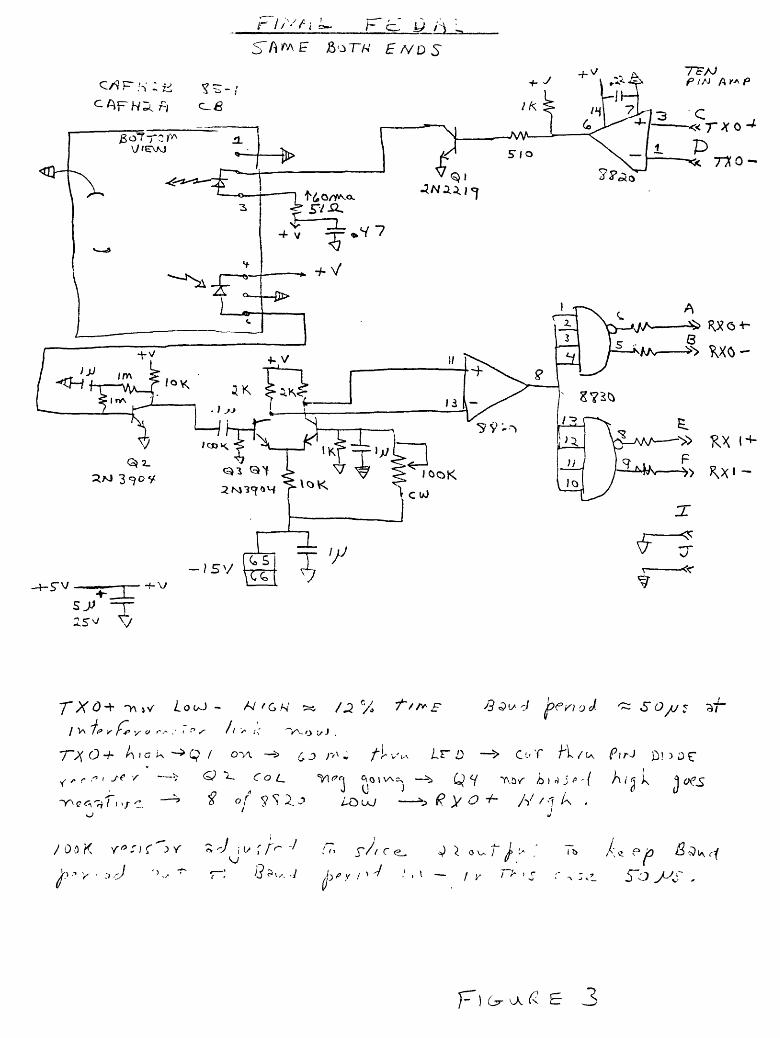
The second interface was used to interconnect two modified FEDAL units used to control and monitor the 85-1. Optically-isolated twisted-pairs were being used, but lightning tended to knock the link out. Since the loss was higher, the first interface would not work. Figure 3 shows the schematic for one end of the link. The circuit was built on a small board and mounted on the rear of the FEDAL unit. We used power from the FEDAL unit. Baud rate was approximately 20 kHz. I doubt if the circuit would work much above that frequency.
The third interface is being used to transmit RS-232 from the PC at the control building to a PC at the 140-ft. During Navy VLBI runs, a Carbon Copy program allows the operators at the 140-ft to monitor the 85-3 telescope parameters. The schematic for this interface is shown in Figure 4. A scope is needed to adjust the 200 K pot for various optical path losses. If the circuit is used on a short path, cut the gain in the first op amp stage by shorting out the 2 meg resistor. I did not put a pot there because of concern for the added capacity in the feed back loop cutting high baud rate response. I would recommend that any future links use a circuit similar to the one in Figure 4. Input and output might need modified, depending on RS-232 vs. TTL vs. balanced line.
I have included some data sheets on miscellaneous parts described and used in the systems.


-V- 5" V
~X,J ^ l* ^ /<Z. r^O/vJT
Pa bRwjeft
no n re
C A; X) UJ
f^^F/lOM ^/c P^OA;T/2A^
irvj^J ^ 0<y
CjCGl CAP-HZ & - OwcW^irvvx^v

+ V
m x! 2Sv?0
SE S3
->>> x
"T^ ^A/C CQV-C^
MT- T:-; 2,
^•-'^ fcv-t "Ti^
j^-itX^-r
r
.r i. iW
1*1 W/J /ot; ioK
^Vo •5'' l<iK
DISC ^ b/sc. JL
CO
UJ
/^&CL COMT^OL - OPT/C. ^;,>
r //"-<Vi }~ cJ y r\
^bn\E fc^Thl EA/DS
3 C ^
8
~r^c<r^( i >/ -: ^ of ^sx^ LO^J —^ £ y o +• H t* k .
S V i ty r A^ -/
5~o J^S ,
p) 6r VA^ E 3

i VO ft- COVXT^OL- A ^ ' ^ L/' / J -- ^s^.^ JL'/'.'
^"^ /v-X?_ bo+W -^Vs.^^
/^oo 3W OOZ^BP -t-Sv
(1.5^3 X VAT A fM
0/ F HXAoxil
A FHLA/g
-K, A^V^I^
M^tyt
4 ir O^A l v/ —
!:<-
•s. (o 9 ■^^
■*-/S.
JSfeL
^■-A^ * ' WT*"*^^ ^0^ /P*^ -ai1^ ouo-^d CAJ>-O^ .cr-v-e^v /DC^-^A
p o c
FtGu^e Y

Fiber Optics
Bidirectional
Connectorized Active Full Duplex Coupler
Model CAF
ADC's CAF component permits bidirectional full duplex signal transmission over a single fiber. The CAF operates at dual wavelengths employing a WDM beam separation technique. The transmit and receive signals, operating at different wavelengths, are separated by the use of the C AFs internal reflective surfaces and specially designed optical coatings that result in excellent optical isolation. The CAFs premounted LED source, PIN detector and SMA or ST connector make it compatible with almost any fiber or cable type. Through the high precision plastic molded body used in this design ADC has simplified the technology of combining and distributing optical signals.
ADC's model CAF, full duplex coupler can be used in a wide range of multimode optical network applications, including, various optical local area networks, data bus extenders, single fiber communication links and optical sensors.
CAF Full Duplex Operation FIBER
Xi = -
X2 = -
INCOMING SIGNAL
PIN DETECTOR
LED SOURCE (X l)
PIN DETECTOR
LED SOURCE (Xz)
Features Single fiber bidirectional communication
Small PC Board mountable package
Single package that incorporates the LED, PIN, SMA or ST compatible connector and fiber optic coupler
Benefits Lower system costs; flexible system design; increased system reliability
No fiber pigtail routing or termination problems; reduced P.C. Board real estate requirements
Fewer separate components; more efficient system performance
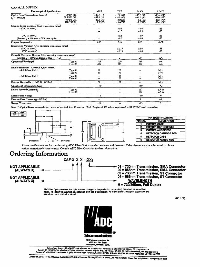
CAF FULL DUPLEX Electro-optical Specifications NUN TYP MAX UNIT
Optical Power Coupled into Fiber (1) 50/125 G.I. -19.2 (12) -17.0(20) -15.2 (30) dBm (f*W) (If = 100 mA) 62.5/125 G.I. -17.0 (20) -14.0 (40) -12.2 (60) dBm (W)
100/140 G.I. -13.0 (50) -10.0(100) -8.2(150) dBm (MW)
Coupled Power Variation (Over temperature range) -40oC to +80oC. +0.5
-1.0 + 1.0 -1.5
dB dB
0oC to +60oC (Emitter If = 100 mA at 50% dutv cycle)
+0.5 -0.5
+ 1.0 -1.0
dB dB
Coupler Responsivity 0.35 0.45 0.55 A/W
Responstvity Variation (Over operating temperature range) -40oC to +80*^
0*C to +60oC - ±0.25
±0.25 ±1.0 ±1.0
dB dB
Crosstalk Current to Detector (Over operating temperature range) (Emitter If = 100 mA, Detector Bias = -5V) _ 2 20 nA
Emitter Bandwidth (+20 mA PP. h = ICOmA) -l.SdBfromlMHz
-3.0dBfromlMHz
Type 01 Type 02
10 10
20 30
MHz MHz MHz MHz
Detector Bandwidth (-3dB@-5V Bias) 50 70 - MHz
Operational Temperature Range -40 - +80 "C
Emitter Forward Current (IA Type 01 Type 02
- 120 120
mAdc mAdc
Detector Bias Voltage -5 - -50 , V
Detector Dark Current (@-5V Bias) - 1 5 nA
Note {ly. Optical Power measured after 1 meter of specified fiber. Connector: SMA (Amphenol 905 style or equivalent) or ST (AT&T type) compatible.
■-YPl- Dili* SMA IIS
a ,57 X
OPT. POSITION IJ
PIN IDENTIFICATION ! PIN NO DESCRIPTION
1 EMITTER CASE 2 EMITTER CATHODE NEG 3 EMITTER ANODE POS 4 DETECTOR CATHODE POS 5 DETECTOR CASE
Above specifications are for coupler using ADC Fiber Optics standard emitters and detectors. Other devices may be substituted to obtain various operational characteristics. Consult ADC Fiber Optics for further information.
Ordering Information CAF-X X X -|XXi
4_ NOT APPLICABLE (ALWAYS X) -*-
NOT APPLICABLE (ALWAYS X) -*■
It 01 = 730nm Transmission, SMA Connector 02 = 865nm Transmission, SMA Connector 03 = 730nm Transmission, ST Connector 04 = 865nm Transmission, ST Connector
WAVELENGTH H = 730/865nm, Full Duplex
ADC Fiber Optics reserves the right to make changes to the produces) or circuit(s) described herein without notice. No liability is assumed as a result of their use or application. No rights under any patent accompany the sale of an- iuch product or circuit.
843 1/87
Tetecommmications ADC Telecommunications, Inc.
4900 West 78m Street Minneapolis, Minnesota 55435
^Salesol(Kes'Ma"ti- GAf404'980-1200• Boston. MA(617)543-9211 • Chicago. 11 (312) 7732428• Dallas TX mu wn-iiw. Denver. CO (303) 850-7016• Fairfield. CT (203) 255-4551 • Hemdon. VA (703) 478-37<»Xir» (a mil 85? 14MTwiiii^L^L ™,!.,c *.~
lond(».u.MOm>U195S.Mo«™.OuebeclS14)677^

OPTICALC ABLE CORPORATION
OPTICAL FIBER All communication grades are available. See Optical Cable Corporation's Fiber Specification Guide for details.
FIBER COATING 500 urn diameter (250 urn on Micro Breakout Cable) *
EXAMPLE: SUB-CABLE
TIGHT BUFFER 900 urn diameter
Elastomeric material
Superior strippability and handling Superior crush and impact resistance
Isolates fiber coating from moisture
(Not available on Micro Breakout Cable)
(Drawing not
ARAMID FIBER STRENGTH MEMBER (DuPont Kevlar)
ELASTOMERIC SUB-CABLE JACKET Provides excellent environmental performance.
SPECIFICATIONS COMMON TO ALL B-SERIES BREAKOUT CABLES MINIMUM BEND RADIUS
UNDER NO TENSILE LOAD: UNDER RATED TENSILE LOAD:
OPERATING TEMPERATURE: STORAGE TEMPERATURE: CRUSH RESISTANCE: IMPACT RESISTANCE: CYCLIC FLEXING: . .
10 X O.D. X^^-POVAWVS ^;"7S 20XO.D. O ^ m^M^ S,S " -20oCTO+85oC -40oCTO +85° C 440 N/cm 50 IMPACTS (EIA-RS-455-25) 2000 CYCLES
UNITS 2 4 6 8
OUTSIDE DIAMhlER mm 7.0 8.0 9.5 11.0 STANDARD BREAKOUT CABLE
WEIGHT
TENSILE LOAD RATING*
kg/km
N
39
1000
51
1600
70
2200
92
2500
RESIDUAL TENSILE LOAD RATING N 200 320 440 500
OUTSIDE DIAMETER mm 6.0 7.0 8.0 9.5
MINI BREAKOUT CABLE
WEIGHT
TENSILE LOAD RATING*
kg/km
N
31
600
42
1000
53
1300
74
1700
RESIDUAL TENSILE LOAD RATING N 120 200 260 340
OUTSIDE DIAMETER mm 5.0 6.0 6.5 7.5
MICRO BREAKOUT CABLE
WEIGHT
TENSILE LOAD RATING*
kg/km
N
23
600
33
1000
36
1300
46
1700
'Tensile load ratings are actual performance data. Installation loads in excess of 2700 N (600 lbs.) are not recom

B SERIES FIBER OPTIC CABLE ORDERING INFORMATION
FIBER TYPE CODE S: 8.7/125 Step Index Single-Mode
-|-^@50/125 Graded Index W: 62.5/125 Graded Index C: 100/140 Graded Index H: 200 urn PCS Step Index
Co<i$lr/ t<rv\ ATTENTION IN dB/km
BANDWIDTH CODE- B: 20 MHz-km D: 100 MHz-km
CE> 200 MHz-km F: 400 MHz-km G: 600 MHz-km H: 800 MHz-km I: 1000 MHz-km
WAVELENGTH CODE CID 850 nm
C: 1300 nm
OPTIONAL: ATTENUATION AND BANDWIDTH AT SECOND WAVELENGTH
C: 50 MHz-km S: 160 MHz-km T: 300 MHz-km U: 500 MHz-km V: 700 MHz-km W: 900 MHz-km
BUFFER CODE /250: 250 urn Diameter /500: 500 urn Diameter
^ /900: 900 urn Diameter Tight Buffer ,._ w wjBPyjw. i' m JIU i map - rai„ OPTIONAL^^IAgCONStTBJUQIIX^jSQDE^ "-tf-^pf—LM-"^Tirfilrlnfii irir'tirmtiriiirilmwmtmmi
EXAMPLE 1: B12-120D-A4FB/2FC/900 = 12 CHANNEL (12 mm DIAMETER) PVC JACKETED MINI BREAKOUT CABLE with 50/125 GRADED INDEX FIBER with a 900 urn TIGHT BUFFER ATTENUATION of 4 dB/km @ 850 nm and 2 dB/km @ 1300 nm BANDWIDTH of 400 MHz-km @ 850 nm and 400 MHz-km @ 1300 nm.
EXAMPLE 2: B06-095C-W4EB/2GC/900 = 6 CHANNEL (9.5 mm DIAMETER) STANDARD BREAKOUT CABLE with 62.5/125 GRADED INDEX FIBER with a 900 urn TIGHT BUFFER ATTENUATION of 4 dB/km @ 850 nm and 2 dB/km @ 1300 nm BANDWIDTH of 200 MHz-km @ 850 nm and 600 MHz-km @ 1300 nm. OPTIONAL POLYURETHANE JACKET.
OPTICALC ABLEOORPQRATION 870 Harrison Avenue. Salem, Virginia 2-41 53 Telex: ^OS-SSO FAX: C"703) 3B9-3B-4B ("703) 3S9-3300 a/87

OPTICALCABLECORPORATIOIM ^QUOTATION*
S"70 Harrison Avenue, Salem, Virginia 2<41 53
CUSTOMER: National Radio Astronomy Observatory DATE: October 20, 1987 P.O. Box 2
PHONE:304-456-2127 Green Bank, W.VA. 24944
CONTACT: ED CHILDERS
FAX: 304-456-2271
ITEM DESCRIPTION & SPECIFICATIONS QTY PRICE TOTAL
1 B02-070D-A6EB/ /900 16,000f $0.40/f $6,400.00
DAYS TO SHIP
21
Special Requirements:
OPTICAL CABLE CORPORATION STANDARD TERMS & CONDITIONS OF SALE ON REVERSE
EXCEPTIONS TO STANDARD TERMS & CONDITIONS ON REVERSE:
Local Representative
Optical Cable Corporation Contact Chuck Surat
dLi-sIr /die** Chuck Surat
National Accounts Execut.ivp TITLE
Octnhpr PO, 1987 DATE
Telex: "705-290 FAX: ("703) 389-9B46 Phone: ("703) 3B9-9900

OPTICALCABLECORPORATION
370 Harrison Avenue, Salem. VA 24153 (703)389-9900
■ ir/v PACKING LIST
SHIPPED TO!
Nat'l Radio Astronomy Obs
Route 28/92
Green Bank, WV 24944-0002
Attn: LEN HOWELL 304-456-2296
ORDER # 3193-A
Customer's P.O.#: G15268
Date of shipment: 04/26/88
Date of order: 04/06/88
Sent Via: CUSTOMER PICK UP
Number of items in this order: 2
ITEM NO. 1- FIBER OPTIC CABLE
B08-110D-4S1XC-4A4FB/2FC/900-CST
ITEM NO. 2- FIBER OPTIC CABLE
B04-080C-S1XC/900
NO. OF PIECE TOTAL
PIECES LENGTH LENGTH UNIT
1 165.0 165.0 M
1 1,785.0 1,785.0 M
1 957.0 957.0 M
1 748.0 748.0 M
4 3,655.0
NO. OF PIECE TOTAL
PIECES LENGTH LENGTH UNIT
441.0
PICKED UP BY_
DATE

'WTELEDYNE SEMICONDUCTOR The Analog Signal Processing Company
TSC232 Dual RS-232 Transmitter/Receiver
General Description The TSC232 from Teledyne Semiconductor is a
dual RS-232 transmitter/receiver that complies with EIA RS-232C guidelines and is ideal for all RS-232C communication links. This device has a 5 V power supply and two charge pump voltage converters that produce +10 V/-10 V power supplies.
The TSC232 has four level translators. Two are RS-232 transmitters that convert TTL/CMOS input levels to 9 V RS-232 outputs. The other two translators are RS-232 receivers that convert RS-232 inputs to 5 V TTL/CMOS output levels. The receivers have a nominal threshold of 1.3V, a typical hysteresis of 0.5 V, and can operate with up to ±30 V inputs.
Features • Meets all RS-232C Specifications • Operates from Single 5 V Power Supply • 2 Drivers and 2 Receivers • Onboard Voltage Quadrupler • ±30 V input Levels • ±9 V Output Swing with +5 V Supply • Low Power CMOS: 5 mA
Functional Diagram
o "O c o o 'E <u
CO G> c >»
♦5V INPUT
16
22*«F*—HCI
22«iF^^C2 5
TTL CMOS INPUTS
TTL CMOS OUTPUTS
TSC232
W
Y, ♦5VTO-10V
VOLTAGE DOUBLER
-10VTO-10V VOLTAGE INVERTER
- T^O"
-O^Rl -
-O^R2 -
I—I 3i<o
l-WW
OTR
6 -10V ^pZZoF
ZZi/F
TD RS-232 OUTPUT
RTS RS-232 OUTPUT
'3 /RD /RD \RS-2
< CTS RS-232 INPUT
CALL 1-800-888-9966
3278 When contacting suppliers, say you saw it in IC MASTER IC MASTER 1989