national radio astronomy observatory socorro, …
TRANSCRIPT

NATIONAL RADIO ASTRONOMY OBSERVATORY SOCORRO, NEW MEXICO
VERY LARGE ARRAY PROGRAM
VLA TEST MEMORANDUM No. 136
POINTING PARAMETERS FOR AN ALT-AZIMUTH MOUNT
Sebastian von Hoerner
May 1982
ABSTRACT
Various causes of repeating pointing errors are rediscussed. Including
gravity and refraction, there should be eight independent pointing parameters.
Two of these should be the same for all 28 antennas and can thus be obtained
with higher accuracy; also, six of the parameters should stay unchanged when
the antenna changes its location, and long-term averages could improve their
accuracy.
Pointing calibration runs should be done at night only, in.order to /
minimize thermal deformations. And they should be done preferably close
to the cardinal angles of elevation and azimuth, in order to minimize the
error correlations. Evaluation of a pointing run should yield the eight
parameters, their eight mean errors, and the 28 independent elements of the
error correlation matrix.
- 2 -
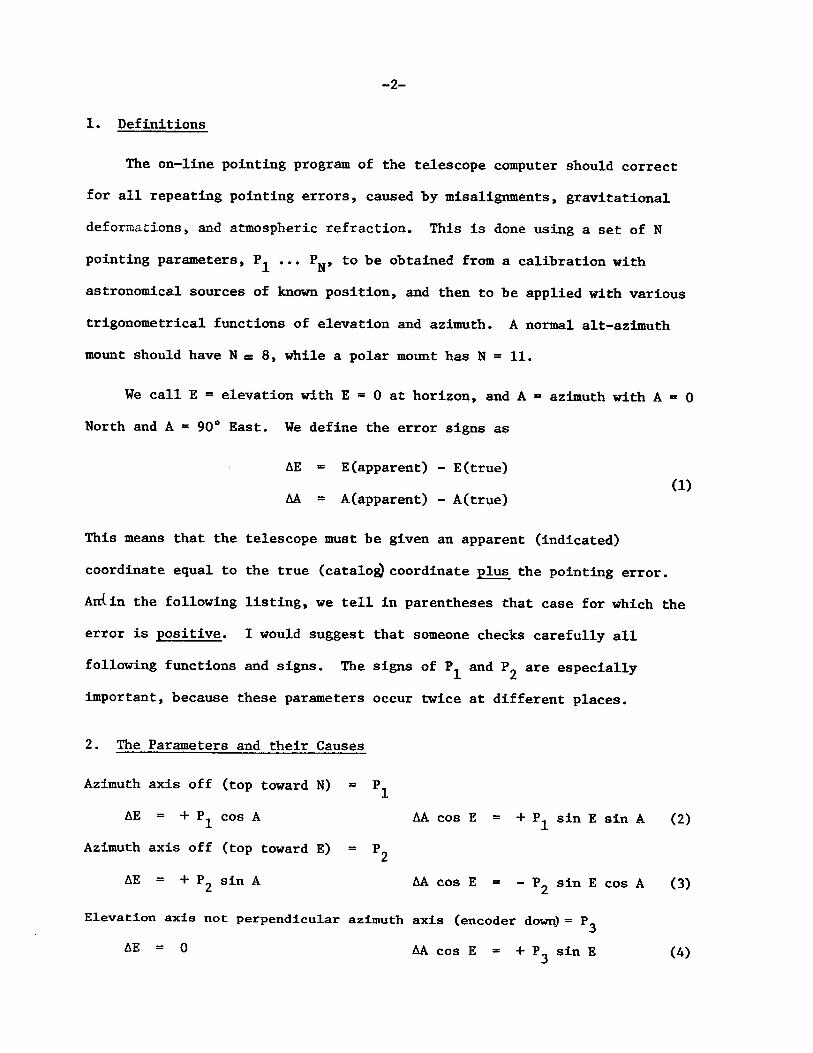
1. Definitions
The on-line pointing program of the telescope computer should correct
for all repeating pointing errors, caused by misalignments, gravitational
deformations, and atmospheric refraction. This is done using a set of N
pointing parameters, P^ ... PN, to be obtained from a calibration with
astronomical sources of known position, and then to be applied with various
trigonometrical functions of elevation and azimuth. A normal alt-azimuth
mount should have N = 8, while a polar mount has N = 11.
We call E = elevation with E = 0 at horizon, and A = azimuth with A = 0
North and A = 90° East. We define the error signs as
AE = E(apparent) - E(true) (1)
AA = A(apparent) - A(true)
This means that the telescope must be given an apparent (indicated)
coordinate equal to the true (catalog coordinate plus the pointing error.
Atriin the following listing, we tell in parentheses that case for which the
error is positive. I would suggest that someone checks carefully all
following functions and signs. The signs of P^ and are especially
important, because these parameters occur twice at different places.
2. The Parameters and their Causes
Azimuth axis off (top toward N) = P^
AE = + P x cos A AA cos E = + P^ sin E sin A (2)
Azimuth axis off (top toward E) = P^
AE = + P 2 sin A AA cos E = - P^ sin E cos A (3)
Elevation axis not perpendicular azimuth axis (encoder down) = P^
AE = 0 AA cos E = + P sin E (4)

- 3 -
Elevation zero, and vertical box offset (box up) = P^
AE = + P 4 AA = 0 (5)
Horizontal box offset (away from encoder) Beam not perpendicular elevation axis (toward encoder) J 5
AE = 0 AA cos E = + P 5 (6)
Azimuth zero (clockwise) = P^
AE = 0 AA = + P 6 (7)
Gravity (primary down, secondary up) = P^
AE = + P 7 cos E AA = 0 (8)
Refraction (rays curve down) = Pg
AE = + P g f (E) AA = 0 (9)
These single contributions then add u,; in the following way:
AE = + P-jCos A + P 2 sin A + P^ + P ? cos E + P g f (E) (10)
AA cos E = + P- sin E sin A - P„ sin E cos A + P 0 sin E + P_ + P, cos E (11) X L j j O
3. Values and Errors
The atmospheric refraction was treated in detail in Engineering Division
Internal Report 101 (May 1976) for the 140-ft pointing program. The value of
P_ changes up to + 30% with weather conditions which is automatically taken o care of, using measurements of temperature, pressure, and water vapor. At
Green Bank, we have PQ = 62 arcsec in the average, which gives about AE = o 6 ^ircmin at E = 10°. Regarding f(E) in equations (9) and (10), we could
neglect the curvature of the Earth and use f(E) = cot E, but then we have a
systematic error of 15 arcsec at E = 10°, and of 60 arcsec at E = 6°. A
useful approximation was derived in Report 101 and is now used at the 140-ft,

which is off by ^ 2 arcsec for E >_ 3°. Regarding the measuring error of our
weather data, and the unknown change of these data with height above ground,
the accuracy obtained for Pg is about + 3 arcsec.
How to obtain the values of all N parameters, and their mean errors as
well, from observations of celestial sources with known positions, is described
in Engineering Division Internal Report 102 (Nov. 1976). The method uses
simple matrix operations and the inversion of a NxN matrix. This empirical
derivation of the mean errors of the parameter values is quite important, if
we want to know how stable or variable the parameters are over longer time
ranges.
The method used for the 140-ft (Report 102) yields the values of the
their statistical mean errors a. , but also the error correlation matrix C., . k ik
A good schedule for a pointing calibration run should try to minimize the
error correlation. This is done by spending most of the observing time close
to the cardinal angles: close to E = 0 and 90°, and close to A = 0, + 90°
and 180°, with equal weight on all. One should not waste too much time at
intermediate angles, for example at 45° where there is no difference between
sine and cosine.
Regarding thermal deformations, the pointing calibration runs should be
done only at night, from several hours after sunset until sunrise. Even dn
most overcast days there is more thermal sky radiation than can be tolerated;
just watch the temperature difference inside and outside of a parked car on
cloudy days.
4. Differences and Changes
We should know which ones of the N parameters must be the same for all
28 antennas of the VLA, or which parameters change when an antenna is moved
- 5 -
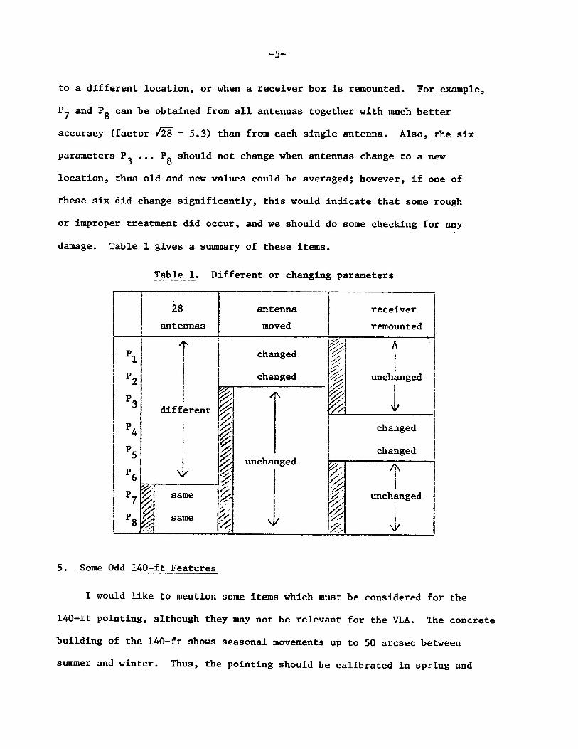
to a different location, or when a receiver box is remounted. For example,
P^ and Pg can be obtained from all antennas together with much better
accuracy (factor 1̂ 28 =5.3) than from each single antenna. Also, the six
parameters P^ ... Pg should not change when antennas change to a new
location, thus old and new values could be averaged; however, if one of
these six did change significantly, this would indicate that some rough
or improper treatment did occur, and we should do some checking for any
damage. Table 1 gives a summary of these items.
Table 1. Different or changing parameters
28
antennas antenna moved
receiver remounted
i P,
5
/N
different
I I I
same
same
f £ v^i
changed
changed /j\
unchanged
i i i i
unchanged
changed
changed
t unchanged
5. Some Odd 140-ft Features
I would like to mention some items which must be considered for the
140-ft pointing, although they may not be relevant for the VLA. The concrete
building of the 140-ft shows seasonal movements up to 50 arcsec between
summer and winter. Thus, the pointing should be calibrated in spring and
fall, if a single set of pointing parameters is wanted; or one should have
two different sets, calibrated in summer and in winter. We also need
different sets for prime focus and Cassegrain. This has been done at the
140-ft.
At very short wavelengths the beam deteriorates, and pointing becomes
a matter of definition. If we define it by the maximum of the main beam, by
"peaking up on a source", the pointing will depend on wavelength X if we
have strong asymmetric sidelobes; at long X, a one-sided sidelobe is smeared
into the main beam and pulls the maximum to its side, but at short X the
sidelobe is a separate independent entity. This gets still more complicated
by the fact that the strength of our one-sided sidelobes depends on the
pointing angle (worst close to horizon). Thus, so far nothing was done
about it.
6. Some Odd VLA Features
Equations (2) and (3) assume a simple planar rotation in azimuth, about
a fixed axis. But in our VLA Test Memo 135, we described two types of
actually observed deviations from this plane of rotation: a "warp" with
second and third order Fourier terms of about 5 arcsec amplitude at yoke
top?which stays constant and repeatable in time^ and a "hysteresis" at a
single narrow azimuth range, which changes erratically between 5 and 26
arcsec.
An on-line pointing program could take care only of the repeatable
warp, which would need 8 additional pointing parameters (amplitude and
phase, second-and third term, for elevation and azimuth). This was not
recommended, because it seems too much trouble for a small gain, and because
the larger variable hysteresis would still remain.