national technical information service … iiesl-tr-91 1111iii~i i~i -30 froude scaling of buried...
TRANSCRIPT

AD-A277 153III 1111III~I I~I IIESL-TR-91 -30
FROUDE SCALING OF BURIED STRUC-TURES USING COAL AND COAL/LEASAS SIMULANTS FOR SAND - VOLUME 11OF 11I- STUDY RESULTS
* - M.A. PLAMONDON, D.E. CHITTY
* APPLIED RESEARCH ASSOCIATES, INC.4300 SAN MATEO BLVD, N.E.,
ALBUQUERQUE NM 87110
DTICJUNE 1993ECT
__________MAR R17 19941FINAL REPORTD
AUGUST 1989 - MARCH 1991
RPPR(WED FOXU LCFLASE:
bJST UnO NLEMJTW
94-08530
ENGINEERING RESEARCH DIVISION O
Air Force Civil Engineering Support Agency
Civil Engineering LaboratoryTyndall Air Force Base, Florida 32403

• -"•• i• • 7 -•, -. • • • ii• , •
NOTICE
PLEASE DO NOT REQUEST COPIES OF THIS REPORT FROM HQ AFCESA/RA (AIRFORCE CIVIL ENGINEERING SUPPORT AGENCY). ADDITIONAL COPIES MAY BEPURCHASED FROM:
NATIONAL TECHNICAL INFORMATION SERVICE5285 PORT ROYAL ROADSPRINGFIELD, VIRGINIA 22161
FEDERAL GOVERNMENT AGENCIES AND THEIR CONTRACTORS REGISTEREDWITH DEFENSE TECHNICAL INFORMATION CENTER SHOULD DIRECT REQUESTSFOR COPIES OF THIS REPORT TO:
DEFENSE TECHNICAL INFORMATION CENTERCAMERON STATIONALEXANDRIA, VIRGINIA 22314

REPORT DOCUMENTATION PAGE Foron App@eo
'WWWW 0 W&ONU 1%~w am dmow WW gineog0 maw go sameg 0 oeaelou, be Ss orof peves me% soaf W W% OR*- "Mc .0.'aftg0 of~.S olrtomg mop" "WWW IV""wa a. *"Ww &"= 6"emore. IVwp OWeru. Owego W a.ssent 12 11
awgigWtwer w I1M ba00ve %% UMA2412 -ogo 584o ft S.0 wSS. USSW'WIU 011Isee 1 vlo~gS tews. CC XK.3
1 AGENCY USEONLY (L~wevebibj 12REPORT DATE 3 REPORT TYPE AND DAME COVtRED) June 1993 1 Technical 890815 to 910331
4~~~ ~ ~ ~ Pf N UBIL UNDING NUMBERS
7. PERFORMING ORGANIZATION kAMEIS) AND ADDRESS(ES) B PERFORMING ORGANIZAT ION
Applied Research Associates, Inc. REPORT NUMBER4300 San Mateo Blvd. N.E., S,,te A220 ARA - 5582Albuquerque, NM 87110
9 SPONSORING /MON rTORIN G AGENCY NAMECS) AND ADDRESS(ES, 10 SPONSORING /MONITOR -%
Air Force Civil Engineering Support Agency AGENCY REPORT NUMBER
HQ AFCESA/RACSTyndall AFE, FL 32403-6001 ESL-TR-91- 30
11 SUPPLEMENTARY NOTES
12& DISTRIBJTION,'AVAIL.A31J1TY STATEMENT 12b DISTRIBUJTION CODE
Approved for public release.Distribution unlimited.
113 ABSTRACT (MAaimum 20 we'c'si
This technical report is divided into two volumes. Volume I presents the resultsof the study, while Volume 11 contains the Appendices. This study describes thedevelopment of the Froude scaling-relat'ionships between the various parameters forthe general problems of both dynamic and static loadings. The results Jbf laboratortests on potential simulant materials are Presented. The rationale for the selec-tion of crushed coal and a mixture of crushed coal' and lead shot as simulants forsand is presented and the results of a crushed coal/cement/water mix as a sirnulartfor concrete.
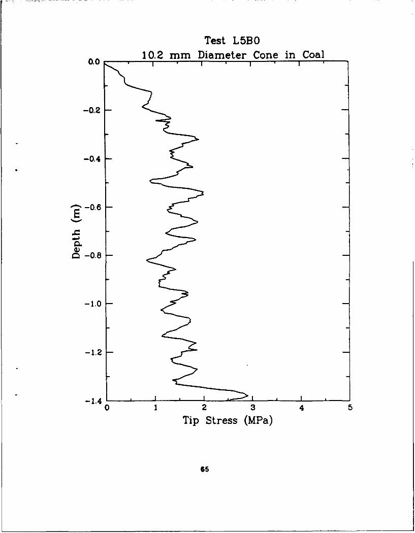
Results of proof-of-principle static tests of cone penetrometers being pushed intosand and the crushed coal and crushed coal/lead shot simulants are presented.Stress at the tip of the penetrator as a function of depth is presented for thefull scale test in sand, the approximate 1/5 scale test in coal, and the approx-imate 1/10 scale test in the coal/lead mixture.
(Continupd anf ha~rk ofpae14. SULIECT TERMS is. NUMBER OF PAGES
Gravity Effects. Simulant Materials, Scaling Methods. Shallow 16 PRICE CODEBuried Structures, Froude Scaling
17. SICURr!Y CLASSIFICATION 18 SECURITY CLASSIFICATION 19 SECURITY CLASSIFICATION 20 LIMITATION OFOF REPORT PW THIS PAGE OF ABSTRACT ABSTRACT
UNCLASSIFIED UNCLASSIFIED UNCLASSIFIED ISame As Report0414 7640-01 -23010No 5s.emotd Frmi 298 (As 2.899
ft"L_________ _ f0 t ANS- Sle 233 18

NUCUftu CLASS-O-"T OF T"i MO'CLISIFI6D 5Y. i
N/A
[DECLASSIFY ON.
N/A
13. ABSTRACT (Continued from page i)
Results of three tests lnvblving a buried explosive loading on a buried cylinderare presented. A 1/10 Replica-scaled reinforced concrete cylinder located insand was subjected to the explosive effects of a 0.39 kg sphere of C-4 explosive,buried 0.6 meters from the edge of the cylinder. Measurements of the free-fieldacceleration and earth stress were made at various ranges from the explosive charge.Measurements of the acceleration of the cylindrical structure were also made. A1/5 scale test using crushed coal as the sand simulant with a 0.31 kg C-4 chargewas also performed. A third test involving a testbed of a coal/lead mixture, at ascale of 1/10, using a 0.039 kg C-4 charge was conducted. The results of this studyare very encouraging as to the use of coal and a coal/lead mixture as Froudesimulants for sand.
I
SECURITY CLASSI')CATJON oF THS PAGE
ii UNCLASSIFIED
EXECUTIVE SUMMARY
The response of buried structures to the explosive affects of conventional weapons is often
determined by testing scale models instead of actual full size structures. The size and material
p•lperties of the scale model structures are determined based upon scaling laws. Most scale
models are based upon the Replica scaling law that reduces the linear dimensions of the structure
while maintaining the same material properties. This scaling law works well when the distortions
resulting the non-scaled acceleration of gravity is not inportant. This report presents the resultsof scale models that use the Froude scaling law that reduces the linear dimensions of the
structure and changes the material properties to avoid distortions resulting from the use of a
constant acceleration of gravity. The results indicate that using coal or a mixture of coal and lead
as a sirnulant for sand can result in model tests that properly replicate the full-scale test conditions.
Accesioi- rFo'
NTIS
Avi IuBy........
Ave•, *.i:d or
Dijt
ii(The reverse of this page is blank)
PREFACE
This report was prepared by personnel of Applied Research Associates,Inc. (ARA) of Lakewood, Colorado 80235, South Royalton, Vermont 05068, andAlbuquerque, New Mexico 87110, under Contract Number F08635-89-C-0204 for theAir Force Civil Engineering Support Agency, Directorate of Research,Development and Acquisition (HQ AFCESA/RA), Tyndall Air Force Base, Florida32403-6001.
This report summarizes work done between September 1989 and March 1991,and discusses the application of the Froude scaling technique to simulate thebehavior of underground structures subjected to conventional weapons effectsfrom a buried burst. The HQ AFCESA/RACS project officer was Capt. Rich Reid.
The authors wish to thank the efforts of Steven Quenneville of the ARAVermont office for his efforts in performing the laboratory tests; Ed Seusy ofthe ARA New Mexico office for investigations into the explosive scaling andcoal detonation/burning issues; Barry Bingham for test calculations of thetests, William Wood of the ARA Colorado office for field test instrumentation;Larry Smith for field construction activities; and Richard Zernow and Dr.Myron Plooster for the data reduction activities; and Don Murrell for the loanof instrumentation from the Explosive Effects Division, Structures Laboratoryof the U.S. Army Waterways Experiment Station, Vicksburg, MS.
This technical report has been reviewed by the Public Affairs Office (PA)and is releasable to the National Technical Information Service, where it willbe available to the general public, including foreign nationals.
-This technical report has been reviewed and is approved for publication.
/" CRD A. Rpt, USAF WILLIAM S. STRICKLAND, GM-14Project Officer Chief, Engineering Research
Division
JON B. ANDERSONChief, Air Base SurvivabilityBranch
v(The reverse of this page is blank.)

TABLE OF CONTENTS
Appendices Title Page
A Description of Candidate Simulant Materials that were not Selected ......... 1B Description of Various Coal and CoaL'oad Mixture ................... 32
C Data From The Static Proof-Of-Principle Cone Penetration Test ........... 157
D Dynamic Cylinder Tests ................................... 70
Measurement List
Test Layouts
Predicted Values
Test Bed Density Measurements
E Data Plots From Dynamic Tests ............................... 96
F Scaled Data Plots From Dynamic Tests .......................... 163
G Composite Nondimensional Data Plots From Dynamic Tests ............. 212
vii(The reverse of this page is blank.)

APPENDIX A
DESCRIPTIONS OF CANDIDATE SIMULANT
MATERIALS THAT WERE NOT SELECTED
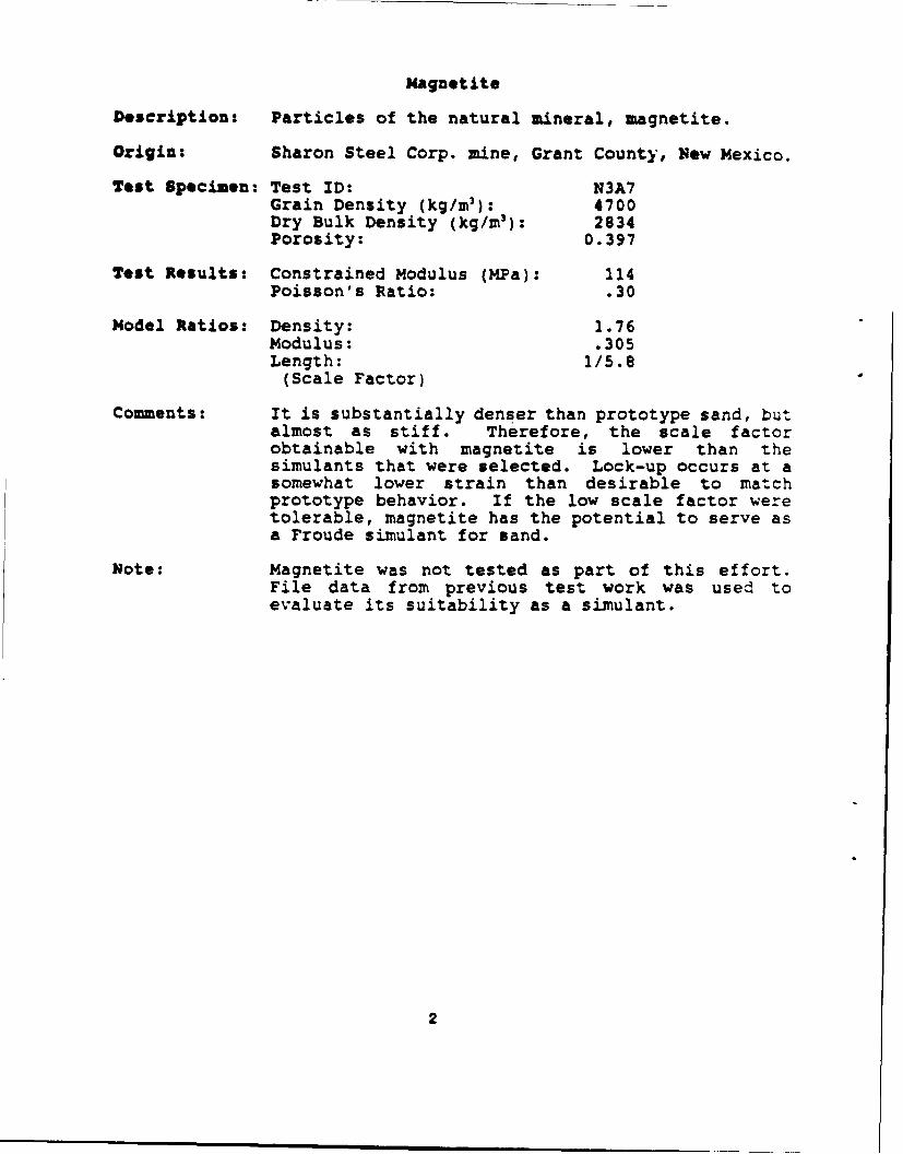
Magnetite
Description: Particles of the natural mineral, magnetite.
Origin: Sharon Steel Corp. mine, Grant County, New Mexico.
Test Specimen: Test ID: N3A7Grain Density (kg/ml): 4700Dry Bulk Density (kg/M 3): 2834Porosity: 0.397
Test Results: Constrained Modulus (MPa): 114Poisson's Ratio: .30
Model Ratios: Density: 1.76Modulus: .305Length: 1/5.8
(Scale Factor)
Comments: It is substantially denser than prototype sand, butalmost as stiff. Therefore, the scale factorobtainable with magnetite is lower than thesimulants that were selected. Lock-up occurs at asomewhat lower strain than desirable to matchprototype behavior. If the low scale factor weretolerable, magnetite has the potential to serve asa Froude simulant for sand.
Note: Magnetite was not tested as part of this effort.File data from previous test work was used toevaluate its suitability as a simulant.
2

Magnetite (N3A7)Uniaxial Strain Test
Stress Ratio (a) = 0.305274.5
2.0
16-
183.0
274.
Oc 91. 5
4)
I-.
0.0 . , , I , I , I , ,0 3 6 9 12 15 18 2 1 24 27 30 33
Axial Strain (M•)
274.5'
S163.0
.1
C
,€91.5
OL 0". I ,I ,II0. 9.5 1803. 274.5 3880 457r.5
Confining Stress (ILPa)
3

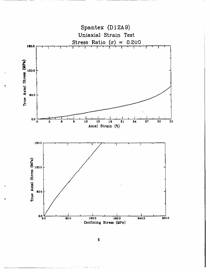
Spantex
Description: Expandable polystyrene beads. Tested in unexpandedstate. Spherical grains of approximately 0.4 mi.diameter.
Origin: Texstyrene Plastics, Inc.3607 North SylvaniaFort Worth, Tx 76111(817) 831-3541
Test Specimen: Test ID: D12A9Grain Density (kg/m 3 ): 940Dry Bulk Density (kg/m 3 ): 694Porosity: 0.262
Test Results: Constrained Modulus (MPa): 75Poisson's Ratio: 0.46
Model Ratios: Density: .43Modulus: .2Length: 1/2.2
(Scale Factor)
Comments: This material exhibited more strain prior to lock-up than the prototype sands. Its Poisson's ratioof almost 0 5 indicates that it behaves almost likea fluid under uniaxial strain loading. While itsmodulus is lower than sand as required, its lowdensity reduces the scale factor to less than 2.Since its deformation behavior does not approximatea scaled sand, and it does not have characteristicsthat would provide a significant scale factor,Spantex is clearly not a suitable sand simulant.
4
Spantex (D 1 2A9)Uniaxial Strain Test
Stress Ratio (a) = 0.200160.0 I * I ' I ' I ' I ' I ' I ' I '-
0
120.0
a
< 60.0VI,-
0.00 3 a 9 12 15 is 21 24 27 30 33
Axial Strain (7.)
1800 I
a
"• 120.0
4c 60.0L
•oJ • I II0.0 60.0 120.0 180.0 240.0 3000.
Confining Stress (MPa)
5
Flake 500
Description: Polytetrafluoroethylene (PTFE) powder.Manufacturer's typical grain size distributionlists 85 percent passing No. 50 and 15 percentpassing No. 100 U.S. Standard sieves. Grains aremuch thinner in one dimension than the others,hence the name Flake. PTFE is the materialcommonly known by the trade name Teflong. It hasvery low intergranular friction.
Origin: Custom Compounding, Inc.6 Crozerville RoadAston, PA 19014(215) 358-1001
Test Specimen: Test ID: D13A9Grain Density (kg/mr): 2160Dry Bulk Density (kg/m 3): 1445Porosity: 0.331
Test Results: Constrained Modulus (MPa): 14Poisson's Ratio: 0.36
Model Ratios: Density: 0.90Modulus: 0.039Length: 1/23
(Scale Factor)
Comments: PTFE has a combination of modulus and density thatresult in high scale factors. Unfortunately, itsstress-strain curve is not a scaled version of thesand curve and its Poisson's ratio is outside therange of prototype values. Also, at approxLna:ely$10/lb, the cost of building a test bed of the sizeunder consideration would have been prohibitive.
6
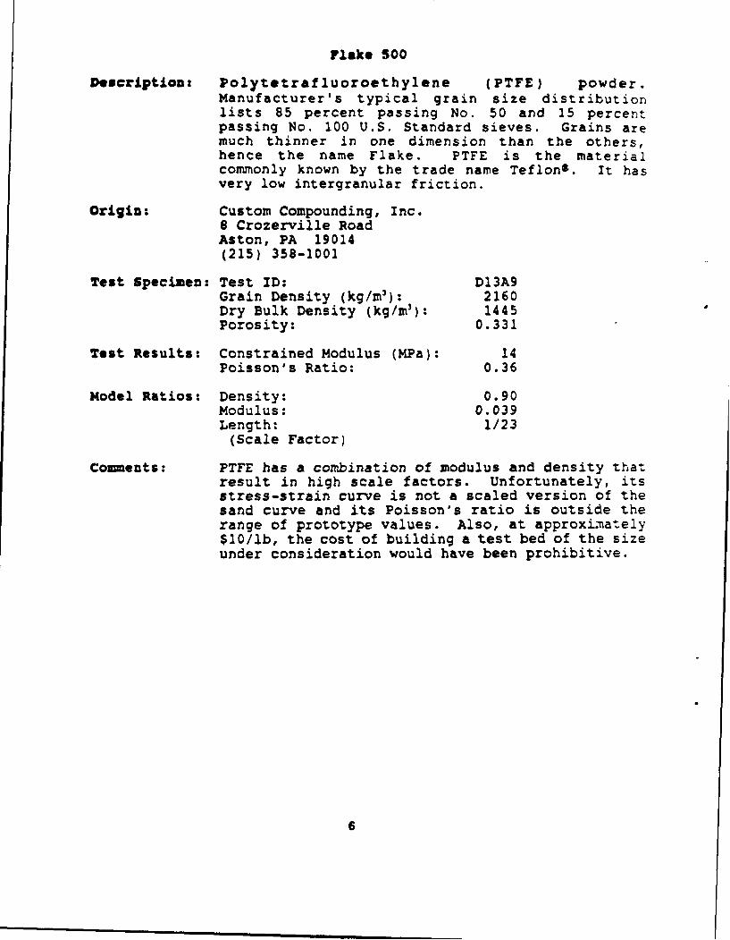
Flake 500 (D13A9)Uniaxial Strain Test
Stress Ratio (a) = 0.039361 * I ' I ' 1 ' 1 ' i
2-34
U1
' 11.7
OLO.
0 3 9 12 15 18 21 24 27 30 33
Axial Strain (%)
35.1
0
S'234
11.7V
IL-
CO0 , I * I , I *
0.0 11.7 214 35.1 468 M56Confining Strew (MPa)
7
Dicaperl CS-10-200
Description: Dicaperl is manufactured as a "lightweight fillerand extender." It is composed of ceramic glassspheres, apparently hollow. The grade tested isspecified to have a particle size range of10-200 pm, with an average of 125 pm.
Origin: Grafco, Inc.3435 W. Lomita Blvd.Torrance, CA 90509(213) 517-0700
Test Specimen: Test ID: D14A9Grain Density (kg/m3): 700Dry Bulk Density (kg/M 3 ): 482Porosity: 0.311
Test Results: Constrained Modulus (MPa): 28Poisson's Ratio: .39
Model Ratios: Density: 0.3Modulus: 0.075Length: 1/4.0
(Scale Factor)
Comments: The prototype sands and many of the other materialstested exhibited initial constrained moduli thatwere nearly constant for approximately the first 10percent of axial strain. For most materials, theslope of that portion of the curve has beentabulated as the constrained modulus. HOwever,Dicaperl has an abrupt change in modulus a-approximately 3 percent axial strain. This featuredisqualifies it as a potential Froude simulant ofsand. The second modulus between zero and 10percent axial strain has been taken as the nominalvalue for purposes of filling out the data tables.
The grain density value of 700 kg/M3 was providedby the manufacturer. It apparently represents theaverage density of an intact grain which containssome inaccessible porosity. It is hypothesizedthat the modulus change at 3 percent axial strainoccurs as a result of crushing of the grains toexpose the trapped pore space.
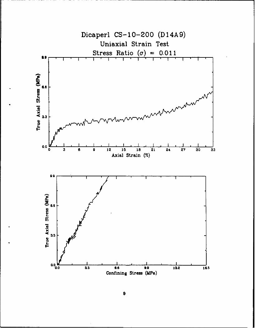
Dicaperl CS-10-200 (D14A9)Uniaxial Strain Test
Stress Ratio (a) = 0.011a ,O * I ' I ' 1 ' I * I ' I ' I ' I
0..
0 a 9 12 15 is 21 24 23 30 33
Axial Strain (%)
9.9
'•IL&
.€33
23-
0.00.0 13 6.6 9.9 112 M5
Confining Stress (MPa)
9
Thermo Rock
Description: Granular material with an appearance of a mineral,rather than organic composition. The grains areirregularly shaped with the largest beingapproximately 1 mm. The smallest pass a U.S.Standard No. 200 sieve.
Origin: Therm-O-Rock Industries, Inc.P.O. Box 50146732 W. Wills RoadChandler, AZ 85224(602) 961-1000
Test Specimen: Test ID: D14B9Grain Density (kg/m 3): not measuredDry Bulk Density (kg/rn 3 ): 199Porosity: not available
Test Results: Constrained Modulus (MPa): 2Poisson's Ratio: 0.45
Model Ratios: Density: 0.12Modulus: 0.005Length: 1/23
(Scale Factor)
Comments: In the uniaxial strain test, this material wasstrained over 50 percent. It was beginning tostiffen at 45 percent. Thus, the stress-straincurve does not approximate a scaled sand. Thesolid mineral portion of this material is denserthan water. Sowever, much of the materialapparently has so much entrapped air that itfloats. Without substantially crushing theexisting grain structure, the material is estimatedto have over 50 percent porosity.
10
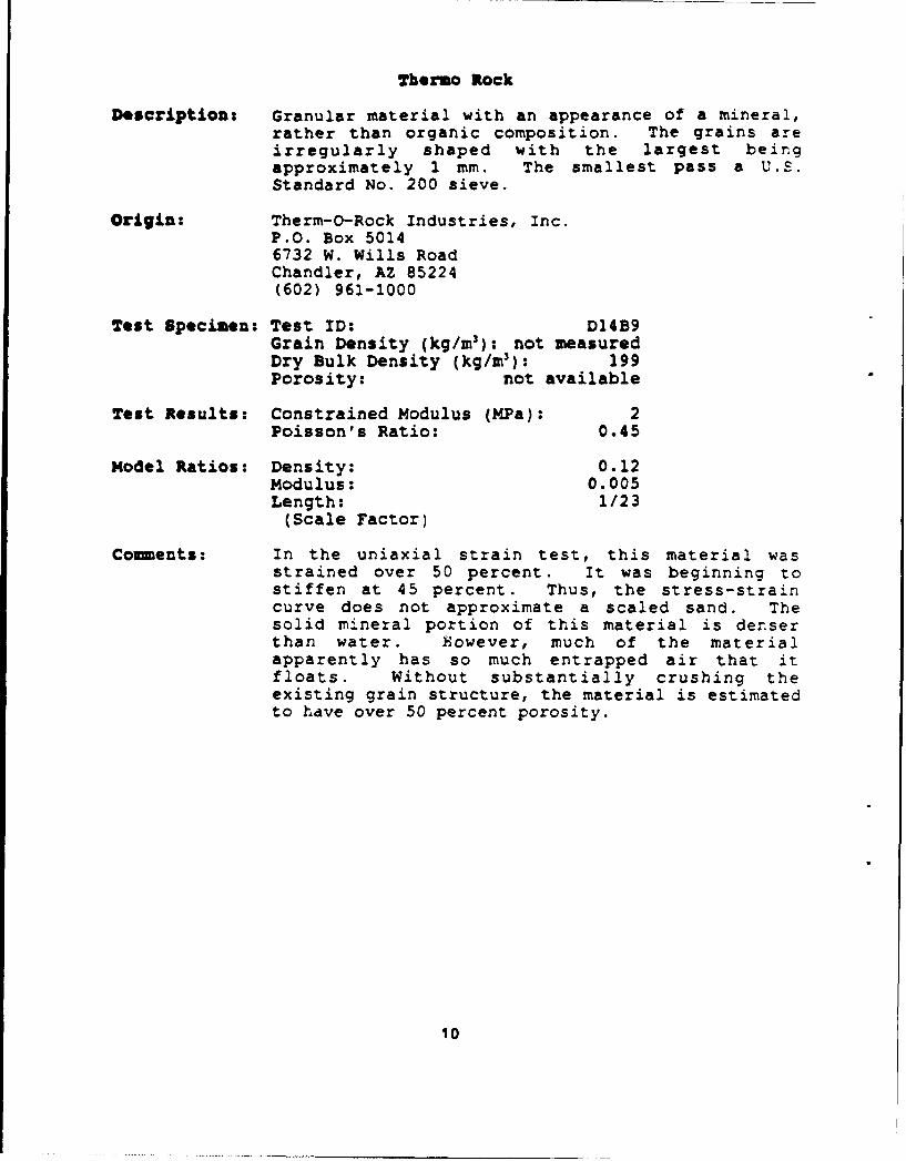
Thermo Rock (D1 4B9)Uniaxial Strain Test
Stress Ratio (a) = 0.0054.5 i ' I ' I I ' I ' I '
8
K
, 1.5
I-
A
0. 0W ro 3 a 9 12 15 18 21 24 27 30 33
Axial Strain (7.)
4.5
'•1.5
OL
0.0.. 045& ,
II
1.11
Q-Cell 600
Description: Fine inorganic microspheres. Will not pass a No.200 U.S. Standard sieve under its own weight, butwill pass if rubbed, possibly due to break-up pfparticles.
origin: The PQ Corporation200 Ceder Grove RoadP.O. Box 258Lafayette Hill, PA 19444-0258(215) 941-2000
Test Specimen: Test ID: D15A9Grain Density (kg/m3): 430Dry Bulk Density (kg/m3): 298Porosity: .307
Test Results: Constrained Modulus (MPa): 6Poisson's Ratio: 0.41
Model Ratios: Density: .19Modulus: .015Length: 1/12(Scale Factor)
Comments: This material was deformed in uniaxial strain toalmost 50 percent without any significant increasein stiffness. Its Poisson's ratio is much higherthan natural sands. Thus, it was not consideredsuitable as a sand simulant.
12
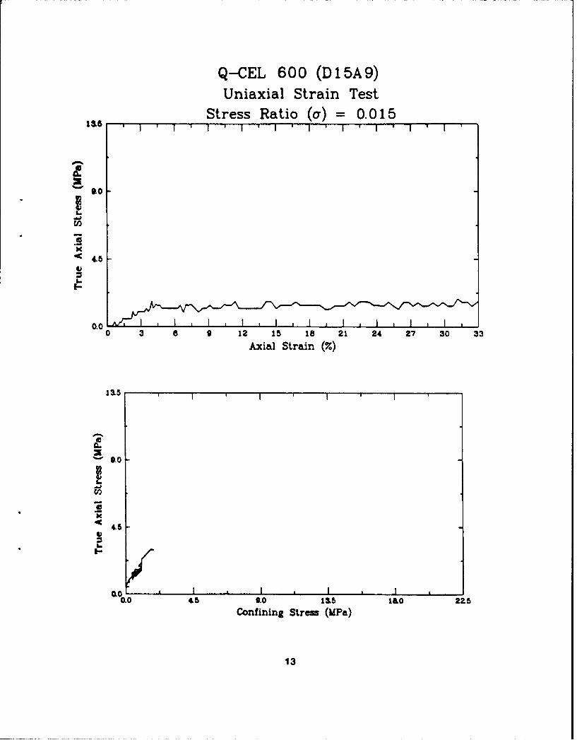
Q-CEL 600 (D15A9)Uniaxial Strain Test
Stress Ratio (a) = 0.01518 ,6 I * I ' '* I ' I *
< 4.6
I-
0.0 L0 3 a 9 12 15 18 21 24 27 30 33
Axial Strain (%)
1.5
S9.0
IC 4.5
*0 i * 1 i
o0.0 45 0.0 1M5 1o 225Confining Stress (MPa)
13
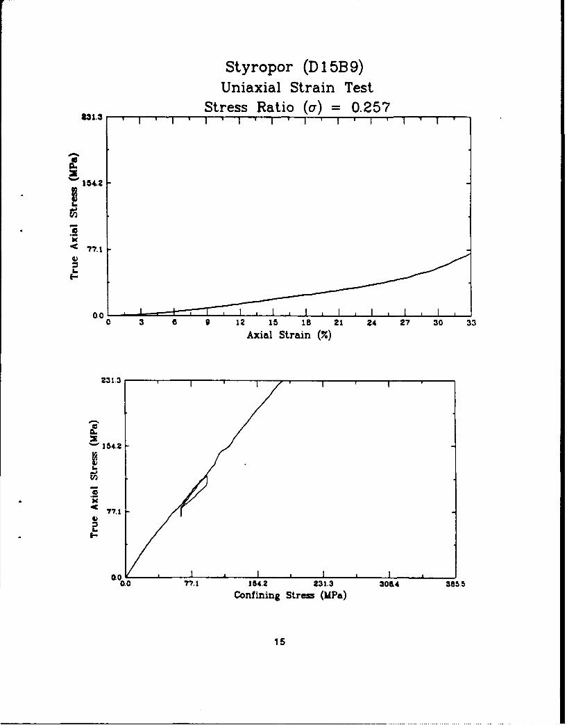
Styropor
Description: Styropor is an expandable polystyrene beadcontaining a volatile hydrocarbon expanding agent.Similar to Spantex.
Origin: BASF Corporation100 Cherry Hill RoadParsippany, NJ 07054(201) 316-3658
Test Specimen: Test ID: D15B9Grain Density (kg/m 3 ): N/ADry Bulk Density (kg/m 3 ): 678Porosity: N/A
Test Results: Constrained Modulus (MPa): 97Poisson's Ratio: 0.42
Model Ratios: Density: 0.42Modulus: 0.26Length: 1/1.6
(Scale Factor)
Comments: The Poisson's ratio is very high, indicatingbehavior that is more fluid-like than sand. This,combined with the low scale factor makes thismaterial unacceptable as a sand simulant.
14
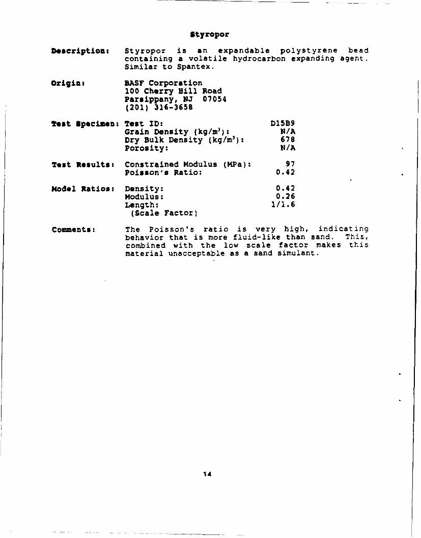
Styropor (D 1 5B 9)Uniaxial Strain Test
Stress Ratio (a) = 0.2572,31.3 ' I ' I * ' I ' I '
01.
184.2
K
'• 77.1
LI-
0.00 3 a 9 12 15 18 21 24 27 30 33
Axial Strain (7)
231.3
0
S154.2
0.0
L-
._2
'•77.1
U-
0.0 * I * I * i I0.0 77.1 154.2 231.3 3084 3a5.5
Confining Stress (MPa)
15
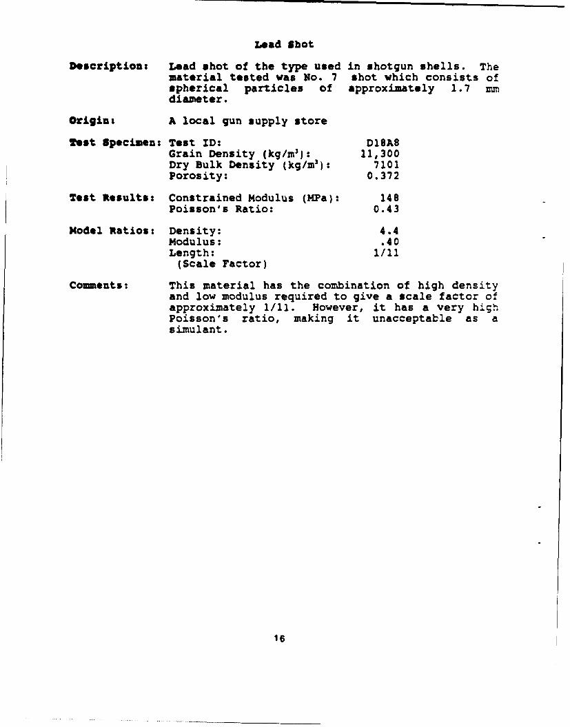
Lead Shot
Description: Lead shot of the type used in shotgun shells. Thematerial tested was No. 7 shot which consists ofspherical particles of approximately 1.7 mmdiameter.
Origin: A local gun supply store
Test Specimen: Test ID: D18A8Grain Density (kg/m 3 ): 11,300Dry Bulk Density (kg/m 3 ): 7101Porosity: 0.372
Test Results: Constrained Modulus (MPa): 148Poisson's Ratio: 0.43
Model Ratios: Density: 4.4Modulus: .40Length: 1/11
(Scale Factor)
Comments: This material has the combination of high densityand low modulus required to give a scale factor ofapproximately 1/11. However, it has a very highPoisson's ratio, making it unacceptable as asimulant.
16
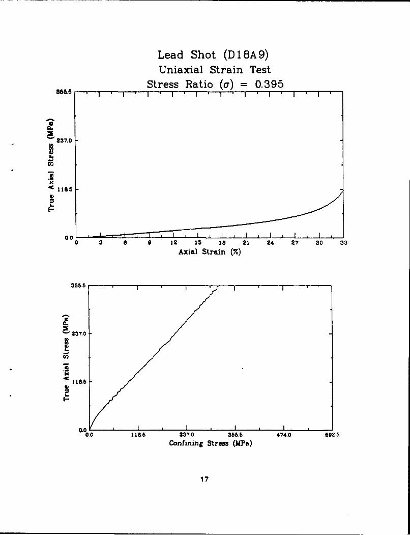
Lead Shot (D 1 8A 9)Uniaxial Strain Test
Stress Ratio (a) = 0.3958655I i I ' ' 1 * ' I '
6
237.0
S1115Lw
0.00 3 a 0 12 15 18 21 24 27 30 33
Axial Strain (%)
355.5
0
• 237.0
I- 5OL
0.0 "p I * I ,I I0.0 115 237.0 355'5 474.0 6OZ5
Confining Stress (UPa)
17

samberko Purge
Description: Clear granular acrylic polymer. Grains areangular, approximating the shape of natural sandgrains. In the form tested, the grains were up toapproximately 5 mm. This material is used to cleaninjection molding equipment.
Origin: Claude Bamberger Molding Compounds Corporation111 Paterson Plank RoadP.O. Box 67Carlstadt, NJ 07072
Test Specimen: Test ID: D22Z9Grain Density (kg/rn3): 1190Dry Bulk Density (kg/m 3 ): 715Porosity: 0.399
Test Results: Constrained Modulus (MPa): 81Poisson's Ratio: .31
Model Ratios: Density: 0.44Modulus: 0.22Length: 1/2.1
(Scale Factor)
Comments: Based on the limited testing prformed, thismaterial could be an acceptable sand simulant.However, the meager scale factor removes it fromconsideration for this effort.
18

Bamberko Purge (D22Z9)Uniaxial Strain Test
Stress Ratio (a) = 0.215
129.0
6 64.5
0.0 1-0 3 8 9 12 15 is 21 24 27 30 33
Axial Strain (%)
193,5
84.5
0.00 64.5 129.0 M95 25&0 32Z5
Confining Stress (lAPa)
19
AlCon PCTFE
Description: Polychloro-Trifluoroethylene Copolymer, whitepowder. Similar to PTFE, except more frictional.
Origin: Allied Signal, Inc.P.O. Box 2332RMorristown, NJ 07960
est Specimen: Test ID: J2A0Grain Density (kg/m 3 ): 2130Dry Bulk Density (kg/mr): 1177Porosity: 0.447
Test Results: Constrained Modulus (MPa): 30Poisson's Ratio: 0.32
Model Ratios: Density: 0.73Modulus: 0.079Length: 1/9.2
(Scale Factor)
Comments: Based on the limited testing performed, thismaterial appears to have the potential to serve asa Froude-scale simulant for sand. The specimen wastested at a rather high porosity and consequently,it underwent almost 40 percent strain without thelock-up that is present on the sand stress-straincurves. However, this could probably be adjustedby increasing the initial density of the specimen.A major drawback of this material is its cost of$40-60 per kg. Since a coal/lead mixture providesat least as favorable simulant properties at a muchlower cost, PCTFE was dropped from consideration asa simulant.
20

Aclon CTFE (J 2AQ0)Uniaxial Strain Test
Stress Ratio (a) =0.07 971.1
47.4
E-
0.010 3 a 9 12 15 18 21 24 27 30 33
Axial Strain (7.)
71.1 T
S47.4
217
L.
0.0 237 47.4 71.1 04.8 1185Confining Stres (MPa)
21
"PTTE 50 Inox
Description: PTFE that is filled with 50% by weight stainlesssteel. This substantially increases the density ofthe material over plain PTFE and, because thefiller interferes with the TFE-TFE bonding, itactually lowers the modulus.
Origin: Ausimont44 Whippany RoadMorristown NJ, 07960-1838
Test Specimen: Test ID: J3BOGrain Density (kg/m 3 ): 3250Dry Bulk Density (kg/mr): 1815Porosity: 0.442
Test Results: Constrained Modulus (MPa): 6Poisson's Ratio: 0.38
Model Ratios: Density: 1.13Modulus: 0.017Length: 1/66
(Scale Factor)
Comments: Based solely on initial constrained modulus anddensity, the filled PTFEs have the largest scalefactors of the materials tested for this effort.Owing to the high initial porosity of the specimentested, its strain to lock-up was excessive incomparison to the prototype sands, and thePoisson's ratio is too high. At over $30/kg, thisis also a very expensive material.
22
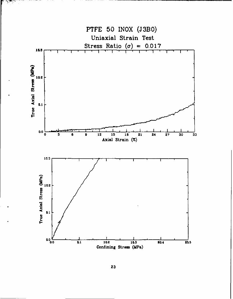
PTFE 50 INOX (J3BO)Uniaxial Strain Test
Stress Ratio (a) = 0.01715. I ' ' I ' I' I ' II I 'i i ' i
*' iM3
0.010 3 a 9 12 15 18 21 24 27 30 33Axial Strain (%)
15.3
0.0
10.2
'._'
K
I-
I I I I
-oo LI 102 13 20.4 2-55
Confining Straw (UPa)
23
PTFE 25 Glass
Description: Similar to PTFE 50 Inox, except that the filling is25% ground glass by weight.
Origin: Ausimont44 Whippany RoadMorristown NJ, 07960-1838
Test Specimen: Test ID: J4A0Grain Density (kg/m 3): 2220Dry Bulk Density (kg/m 3 ): 1165Porosity: 0.475
Test Results: Constrained Modulus (MPa): 5Poisson's Ratio: 0.38
Nodel Ratios: Density: 0.72Modulus: 0.010Length: 1/76
(Scale Factor)
Comments: Based solely on initial constrained modulus anddensity, the filled PTFEs have the largest -:alefactors of the materials tested for this e!,jrt.Owing to the high initial porosity of the specimentested, its strain to lock-up was excessive incomparison to the prototype sands, and thePoisson's ratio is too high. At over $30/kg, thisis also a very expensive materia2.
24
PTFE 25 Glass (J4AO)Uniaxial Strain Test
Stress Ratio (a) = 0.01010O ' 1 I * I ' I * i ' 1I I ' I ' I ' I
S aoL
I0-
0.00 3 a 9 12 15 18 21 24 27 30 33
Axial Strain (.)
9.0
0
0.0
I,-
0.0 * I * i * I *
0.0 10 t.o .O izo 15-0Confining Stress (MPa)
25

Flake 500 with Fiber
Description: In an effort to raise the friction of PTFE, a mixwas made of Flake 500 and polymer fibers (exactcomposition unknown) of the type that are use tomake fiber reinforced concrete.
Origin: See Flake 500 and a local concrete batch plant.
Test Specimen: Test ID: J4B0Grain Density(kg/m3 ): Fiber density not knownDry Bulk Density (kg/m 3): 1400Porosity: Not known
Test Results: Constrained Modulus (MPa): 15Poisson's Ratio: 0.41
Model Ratios: Density: 0.41Modulus: 0.87Length: 1/21
(Scale Factor)
Comments: The addition of fiber to the Flake 500 did nctsubstantially modify its properties. The measuredPoisson's ratio is actually higher, opposite thedesired trend.
26
Flake w/Fiber (J4BO)Uniaxial Strain Test
Stress Ratio (a) = 0.040
,,ac
0•1.0
0 3 6 9 12 15 IS 21 24 27 30 33Axial Strain (7.)
36.0I
•"24,0
.2
Siao
4I)
I-
0.00.0 3 o 124 1 318 , 46o 2SOL
CoAxining Streai (UPS)
27
Barite
Description: Barite (barium sulfate) is a yellowish brownmineral. Because of its high grain density, finelypowdered barite is used in suspension with water toform a high density fluid for well drillingoperations.
Origin: NL Baroid DivisionNL Petroleum ServicesHouston, TX
Test Specimen: Test ID: J25A0Grain Density (kg/m'}: 4480Dry Bulk Density (kg/m 3): 2842Porosity: 0.366
Test Results: Constrained Modulus (MPa): 121Poisson's Ratio: 0.31
Model Ratios: Density: 1.76Modulus: .324Length: 1/5.5
(Scale Factor)
Comments: Based on the tests performed, this material couldpossibly be used as a Froude scale simulant forsand. It has a rather modest scale factor, and issubstantially more expensive than coal for the samescale factor.
28
Barite (J25A0)Uniaxial Strain Test
Stress Ratio (a) = 0.324
0.0291.6 ,
194.4
S97.2
I-
4)
0.00.3 6 12 1 15 21 24 27 30 33
Axial Strain (7.)
291.62
S194.4
I
'•97.2I)
a--
60 I ,I I I
0.0 97.2 10414 291.8 3888 486.o
Confining Stress (liP.)
29
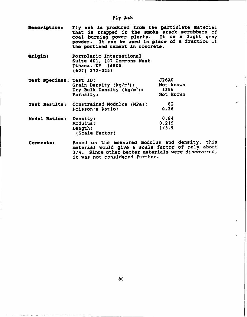
Fly Ash
Description: Fly ash is produced from the partiulate materialthat is trapped in the smoke stack scrubbers ofcoal burning power plants. It is a light graypowder. It can be used in place of a fraction ofthe portland cement in concrete.
Origin: Pozzolanic InternationalSuite 401, 107 Comnons WestIthaca, NY 14805(607) 272-3257
Test Specimen: Test ID: J26A0Grain Density (kg/m 3): Not knownDry Bulk Density (kg/m 3): 1356Porosity: Not known
Test Results: Constrained Modulus (MPa): 82Poisson's Ratio: 0.36
Model Ratios: Density: 0.84Modulus: 0.219Length: 1/3.9
(Scale Factor)
Comments: Based on the measured modulus and density, thismaterial would give a scale factor of only about1/4. Since other better materials were discovered,it was not considered further.
30
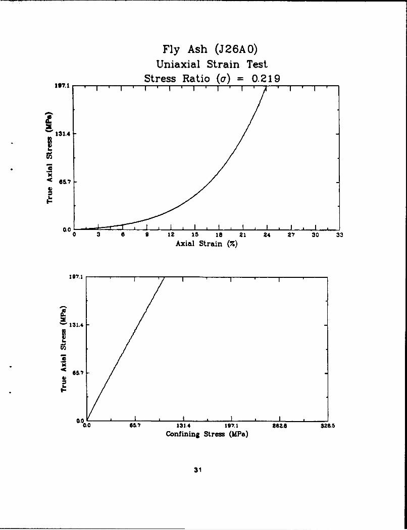
Fly Ash (J26A0)Uniaxial Strain Test
Stress Ratio (a) = 0.219107.1
131.4
6&-0.0•
0 3 a 9 12 15 18 21 24 27 30 33
Axial Strain (•)
197.1
0• 131.4
OL
0.0 I , I * I I0.0 65.7 131.4 197.1 Moae 32&55
Confining Stress (MPa)
31
APPENDIX B
DESCRIPTION OF VARIOUSCOAL AND COAL/LEAD MIXTURES
32
COAL
Three different types of coal were tested in the course of thesearch for suitable simulants. Of those, two, Anthracite coal andso-called Denver coal were tested and eliminated. Specificinformation concerning the origin of these materials is not known.
The bituminous coal that was selected for use as a Froudescale sand simulant was purchased from a coal broker in New Jersey:
Kennedy and Decker(201) 635-0731
The shipping labels on the barrels of coal indicate that it carefrom:
Bradford Coal Co., Inc.P.O. Box 368Bigler, Pennsylvania 16825
The three different coals have different grain densities, asfollows:
Grain Density
Material (kg/M 3 )
Anthracite Coal 1650
Bituminous Coal 1330
"Denver" Coal 1460
33

LEAD
Lead in two different forms was used in various phases of thesimulant selection laboratory testing.
No. 7 Lead Shot. This material, which was intended for usein shotgun shells, was obtained from a local sporting goodsstore. It is designated No. 7 and consists of nominallyuniform spherical particles of 1.7 mm diameter.
Free Flow Lead Shot. This material consists of particleswith a range of sizes, all smaller than the No. 7 shot. Itsspecifications list the following grain size characteristics:
0.41 - 1.14 mm 90 percent0.23 - 0.41 mm 10 percent
A grain size analysis of a small sample of free flow shotproduced results essentially confirming that specificaticn.This material was supplied as Product Code 20900 by:
Taracorp Industries, Inc.16th and Cleveland BoulevardGranite City, Illinois 62040(618) 451-4400
The density of solid lead grains is 11,300 kg/m 3 .
34
Anthracite Coal (D20A9)
Description: This hard coal was manually crushed and onlymaterial that passed a No. 10 sieve was used. Inaddition, approximately half of the portion passinga No. 50 sieve was removed.
Test Specimen: Dry Bulk Density (kg/mr): 956Porosity: .420
Test Results: Constrained Modulus (MPa): 43Poisson's Ratio: 0.38
Model Ratios: Density: 0.59Modulus: 0.114Length: 1/5.2
(Scale Factor)
Comments: This material shows promise as a simulant, but alarger scale factor is desired.
35
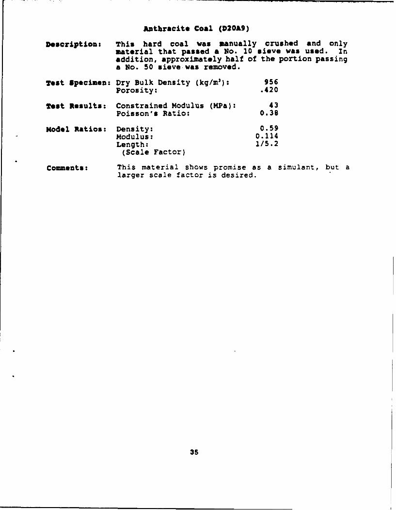
Anthracite Coal (D20A9)Uniaxial Strain Test90.o
4 30.0
0.0 0 3 6 9 12 15 is 21 24 27 30 33
Axial Strain (%)
90.0
0
3 60.0
K
30.0
I-.
0.0 30.0 6.0 90.0 120.0 150.0Confining Straw (MPa)
36
bituminous Coal (J230)
Description: As with the anthracite, this soft coal was manuallycrushed and only material that passed a No. 10sieve was used for preparation of the specimen.
Test Specimen: Dry Bulk Density (kg/m 3 ): 988Porosity: .257
Test Results: Constrained Modulus (MPa): 53Poisson's Ratio: 0.34
Model Ratios: Density: 0.61Modulus: 0.141Length: 1/4.4
(Scale Factor)
Cotments: Due to the softness of bituminous coal, some of thegrains were apparently crushed during samplepreparation, as evidenced by the very low porosity.As a result, the modulus measured in this test washigher than the previous anthracite coal test(D20A9).
37

Bituminous Coal (J2BO)Uniaxial Strain Test
,0L0
6 0.0
.30.0
I-,
0 3 a 9 12 15 18 21 24 27 30 33
Axial Strain (7o)
90.0
0
3 60.0
30.0
V
0 .0 I, , I I0.0 30.0 6OL0 90.0 120.0 150.0
Confining Strew (MPa)
38

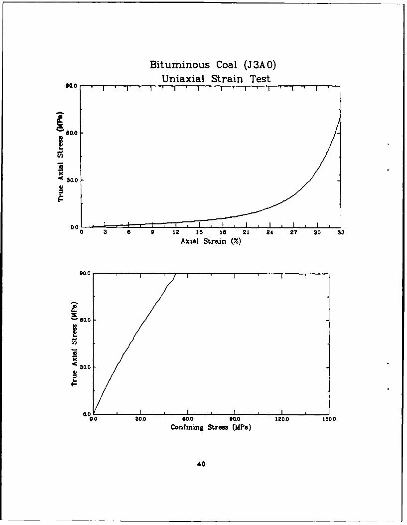
bituminous Coal (J3AO)
Description: The material tested here was similar to theprevious bituminous coal test (J2BO), except thatan effort was made to keep the porosity up. Allmaterial passing a No. 50 sieve was removed beforepacking the specimen, and care was taken not toover compact it.
Test Specimen: Dry Bulk Density (kg/mr): 857Porosity: .356
Test Results: Constrained Modulus (MPa): 24Poisson's Ratio: 0.33
Model Ratios: Density: 0.53Modulus: 0.064Length: 1/8.3
(Scale Factor)
Comments: This test produced a significantly lower modulusthan the other bituminous coal test, apparently asa result of the lower density.
39
Bituminous Coal (J 3A 0)Uniaxial Strain Test
SOLO ,
K*. 30.0
E6-
0.00 3 a 9 12 15 is 21 24 27 30 33
Axial Strain (7.)
90.0
F.._
3 0.0
03.0
S
0.0 o0.0 6ao 00O0 120.0 150.
Confining Strea (MPa)
40
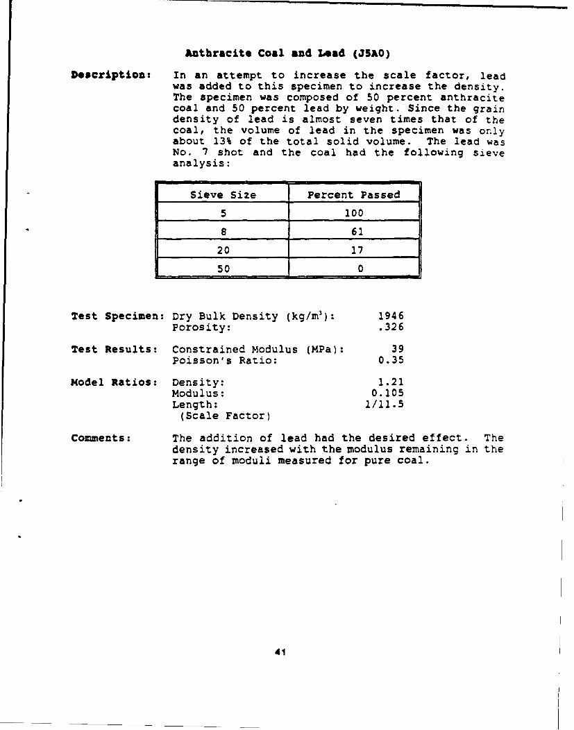
Anthracite Coal and Lead (J5AO)
Dfscription: In an attempt to increase the scale factor, leadwas added to this specimen to increase the density.The specimen was composed of 50 percent anthracitecoal and 50 percent lead by weight. Since the graindensity of lead is almost seven times that of thecoal, the volume of lead in the specimen was onlyabout 13% of the total solid volume. The lead wasNo. 7 shot and the coal had the following sieveanalysis:
Sieve Size Percent Passed
5 100
8 61
20 17
50 0
Test Specimen: Dry Bulk Density (kg/M 3 ): 1946Porosity: .326
Test Results: Constrained Modulus (MPa): 39Poisson's Ratio: 0.35
Model Ratios: Density: 1.21Modulus: 0.105Length: 1/11.5
(Scale Factor)
Comments: The addition of lead had the desired effect. Thedensity increased with the modulus remaining in therange of moduli measured for pure coal.
41
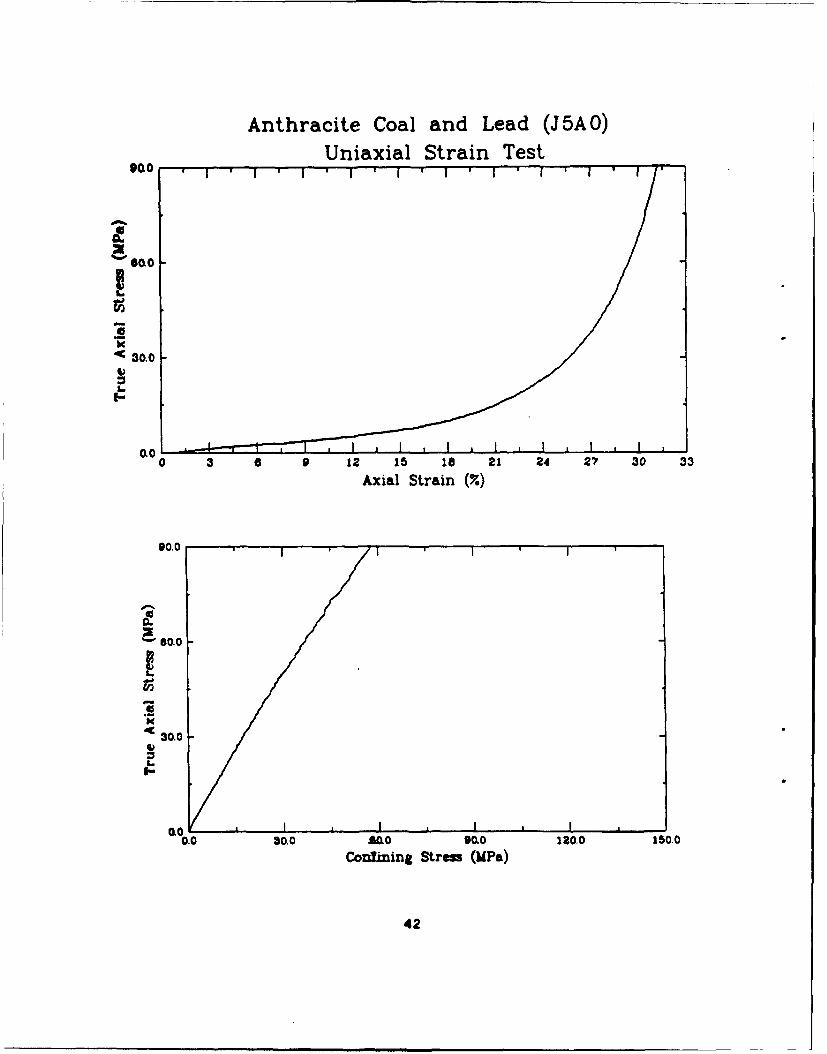
Anthracite Coal and Lead (J 5A 0)Uniaxial Strain TestOQo
X
0 30.0
a-I-
OL00 3 a 9 12 15 la 21 24 27 30 33
Axial Strain (•,)
90.0
U
- 80.0
30.0
gO iIa , I I0.0 30.0 LDo 90o 120.0 150.0
Conlmiing Stress (UP*)
42
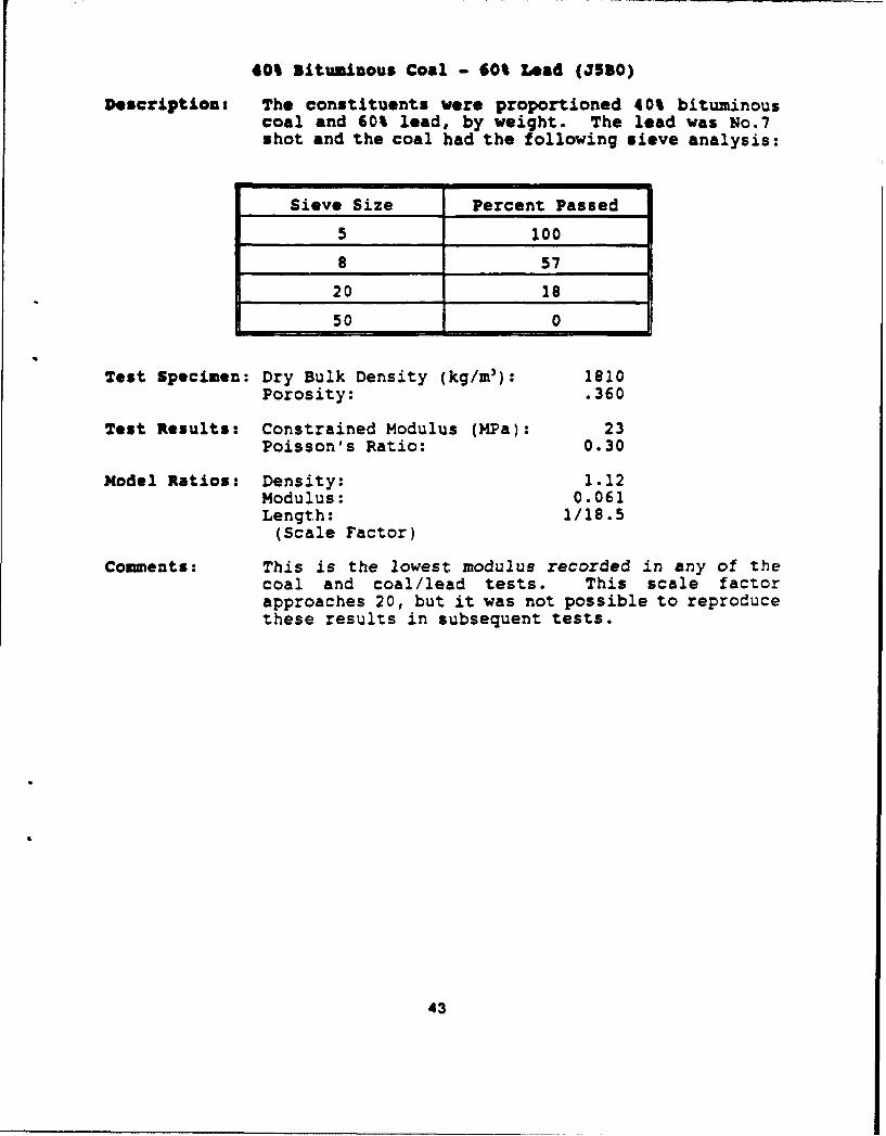
40% situmisous Coal - 60t Lead (35s0)
Description: The constituents were proportioned 40% bituminouscoal and 60% lead, by weight. The lead was No.7shot and the coal had the following sieve analysis:
Sieve Size Percent Passed
5 100
$ 57
20_1_
50 0
Test Specimen: Dry Bulk Density (kg/M3): 1810Porosity: .360
Test Results: Constrained Modulus (MPa): 23Poisson's Ratio: 0.30
Nodel Ratios: Density: 1.12Modulus: 0.061Length: 1/18.5
(Scale Factor)
Comments: This is the lowest modulus recorded in any of thecoal and coal/lead tests. This scale factorapproaches 20, but it was not possible to reproducethese results in subsequent tests.
43
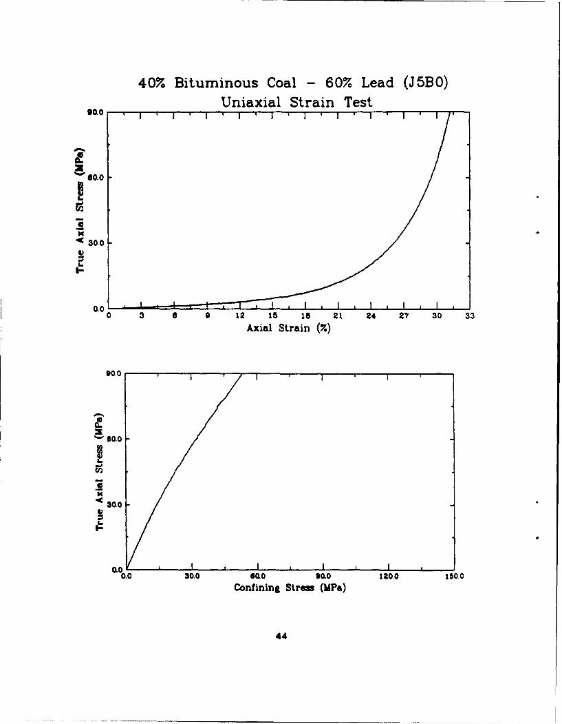
40% Bituminous Coal - 60% Lead (J5BO)Uniaxial Strain Test
< 30.0
9LO
a-
0.00 3 6 9 12 15 18 21 24 27 30 33
Axial Strain (%)
90.0
S50.0
30.0
0.0 30.0 60o 90.0 120.0 1500Confining Straw (MPa)
44
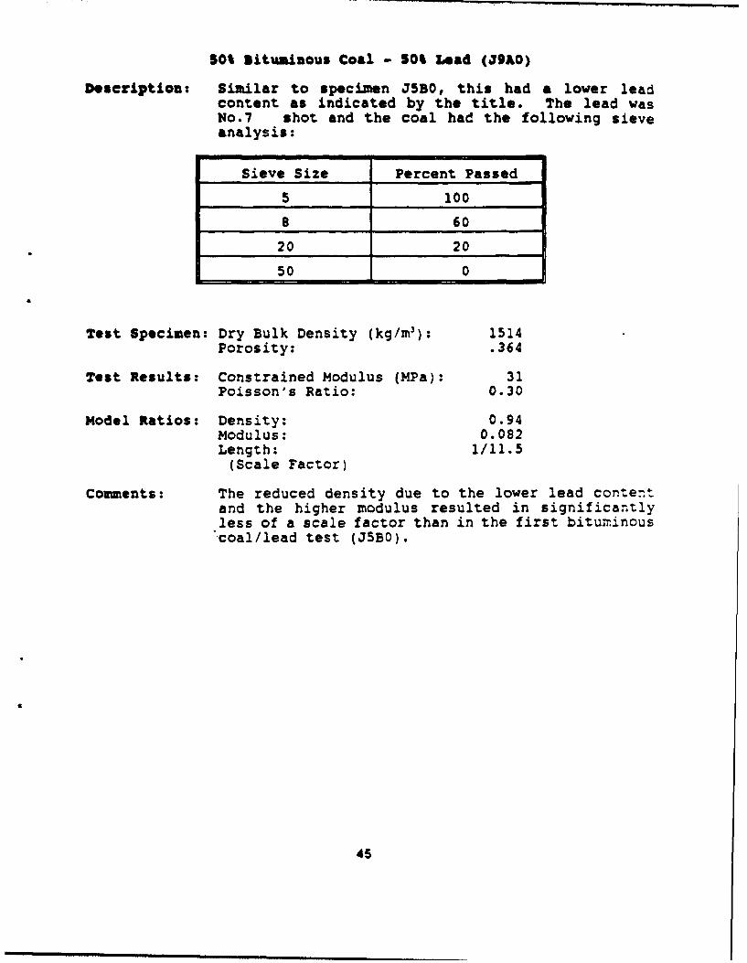
50% bituminous Coal - so% Lead (j3AO)
Description: Similar to specimen J5B0, this had a lower leadcontent as indicated by the title. The lead wasNo.7 shot and the coal had the following sieve
Sieve Size Percent Passed
5 100
8 60
20 20
50 0
Test Specimen: Dry Bulk Density (kg/M 3): 1514Porosity: .364
Test Results: Constrained Modulus (MPa): 31Poisson's Ratio: 0.30
Model Ratios: Density: 0.94Modulus: 0.082Length: 1/11.5
(Scale Factor)
Comments: The reduced density due to the lower lead contentand the higher modulus resulted in significantlyless of a scale factor than in the first bitumninous"coal/lead test (JSBO).
45
50% Bituminous Coal - 50% Lead (J9AO)Uniaxial Strain TestSOO
< 30.0
I-
IO
0.01o 3 o 0 12 15 18 21 24 27 30 33
Axial Strain (7.)
90.0
' 0.0I
30.0 ,
aoo0.0 30.0 6Sa0 0.0 120.0 150.0
Confining Strew (MPa)
46
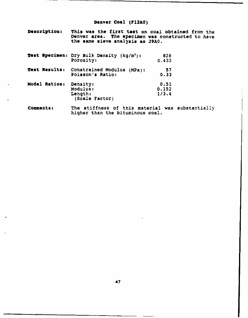
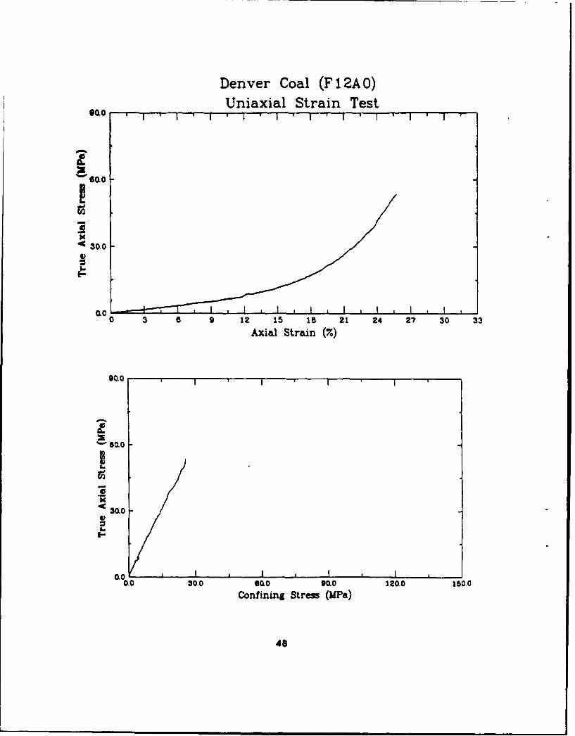
Denver Coal (712AO)
Description: This was the first test on coal obtained from theDenver area. The specimen was constructed to havethe same sieve analysis as J9A0.
Test Specimen: Dry Bulk Density (kg/m 3 ): 828Porosity: 0.433
Test Results: Constrained Modulus (MPa): 57Poisson's Ratio: 0.33
Model Ratios: Density: 0.51Modulus: 0.152Length: 1/3.4
(Scale Factor)
Comments: The stiffness of this material was substantiallyhigher than the bituminous coal.
47
Denver Coal (F 12AO)Uniaxial Strain Test
*0.0 * I ' I ' I ' I ' I ' I ' 1 ' I ' '
30.0
I
*• 30.0
I-,
&00
0 3 6 9 1L 15 98 2 2204 27 30 33
Axial Strain (%)
90.0 -- •I
S60.0
U,,
44,
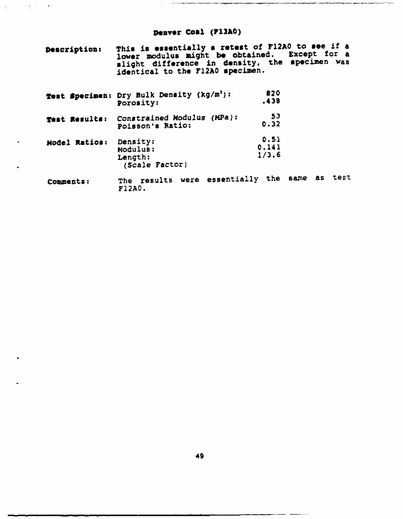
Denver Coal (13AO)
Description: This is essentially a retest of F12AO to see if a
lower modulus might be obtained. Except for a
slight difference in density, the specimen was
identical to the F12AO specimen.
Test Specimen: Dry Bulk Density (kg/m 3): 820Porosity: .438
Test Results: Constrained Modulus (MPa): 53Poisson's Ratio: 0.32
Model Ratios: Density: 0.51Modulus: 0.141Length: 1/3.6
(Scale Factor)
Comments: The results were essentially the same as testF12AO.
49

Denver Coal (F 13A0)Uniaxial Strain Test
II
30.0 '
OL.
0 3 6 9 12 15 18 21 24 27 30 33
Axial Strain (7.)
9 0.0
30.0
[-,
0.0 30.0 60.0 00.0 120.0 150.0Confining Stress (MPa)
so
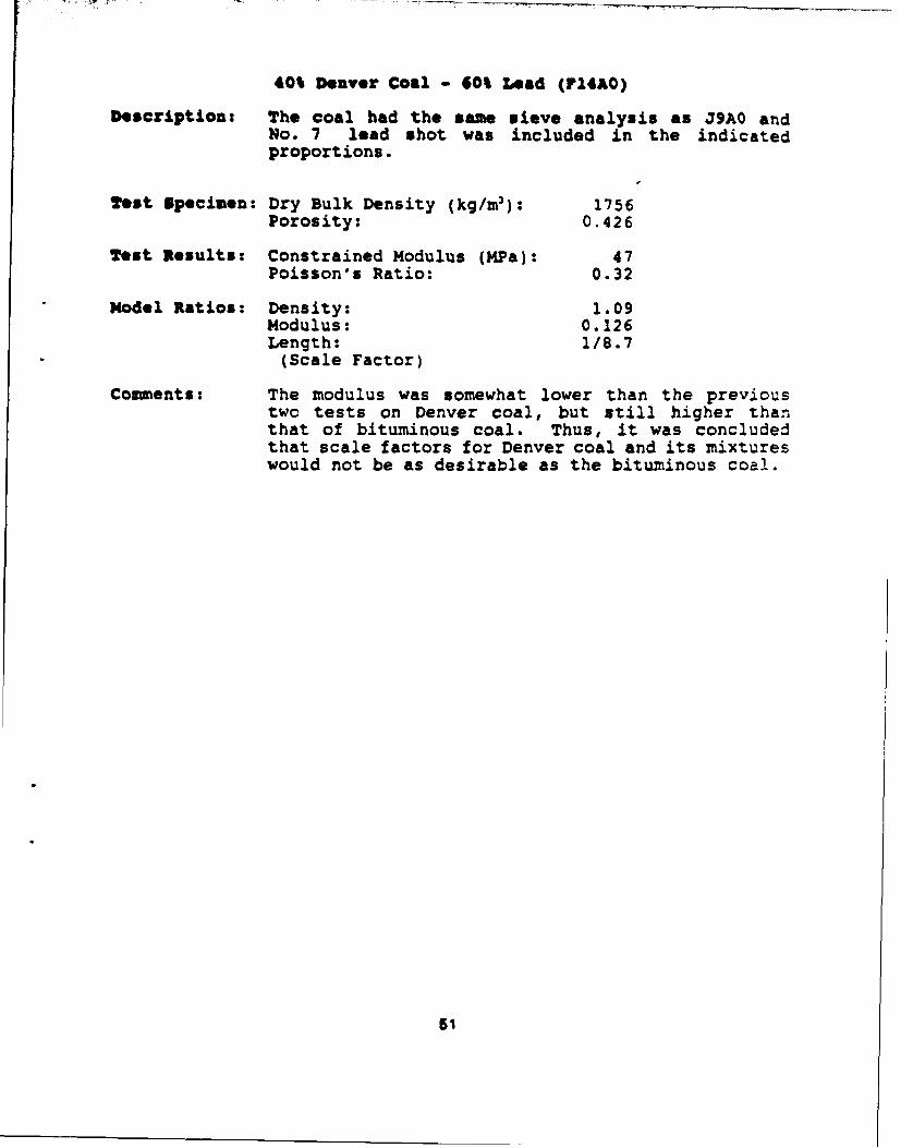
40% Denver Coal - 60% Lead (qu4AO)
Description: The coal had the same sieve analysis as 39AO andNo. 7 lead shot was included in the indicatedproportions.
Test Specimen: Dry Bulk Density (kg/m 3): 1756Porosity: 0.426
Test Results: Constrained Modulus (MPa): 47Poisson's Ratio: 0.32
Model Ratios: Density: 1.09Modulus: 0.126Length: 1/8.7
(Scale Factor)
Comments: The modulus was somewhat lower than the previoustwo tests on Denver coal, but still higher thanthat of bituminous coal. Thus, it was concludedthat scale factors for Denver coal and its mixtureswould not be as desirable as the bituminous coal.
5I

40% Denver Coal - 60% Lead (F14AO)Uniaxial Strain Test
00.0 ' I ' ! ' i * I I * I i I " ! '
60.
30.0
I-o
0.0 , , , , I , , I
0 3 6 9 12 15 is 21 24 27 30 33
Axial Strain (%)
90.0
30.0
•0 30.0 SOLO 90.0 220.0 150 0Conf ining Stress (UP&)
52

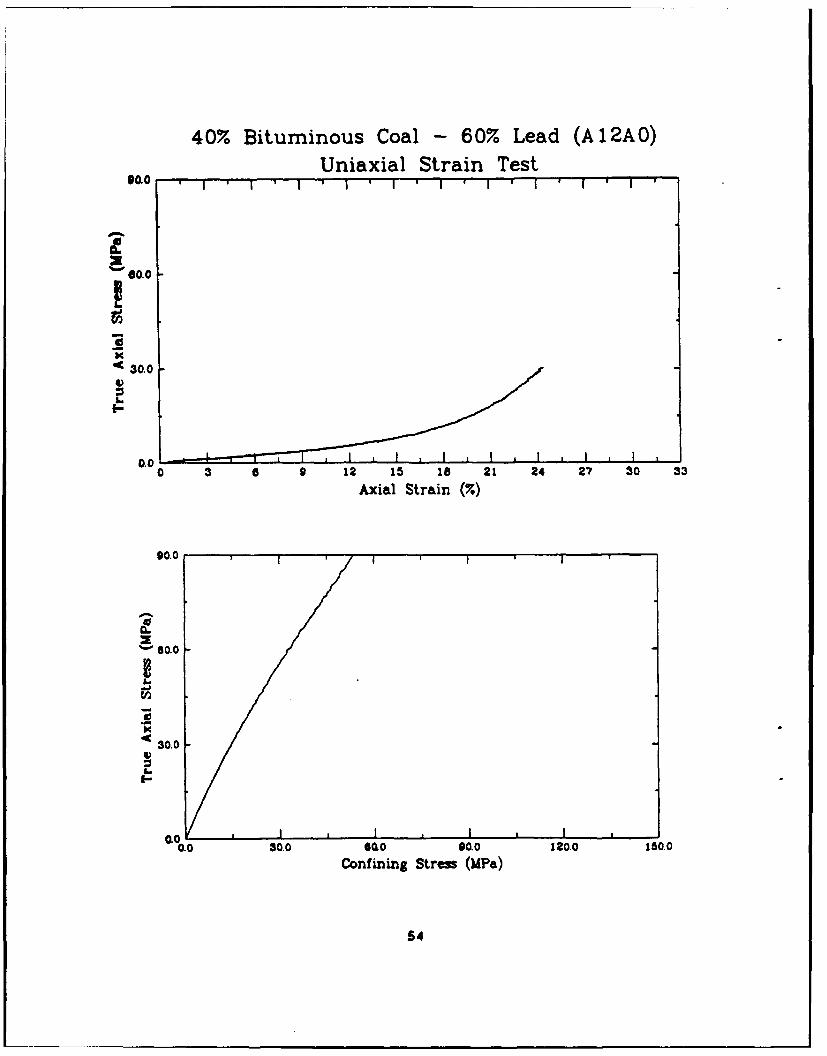
40% Bituminous Coal - 60% Lead (AI2AO)
Description: The coal used to construct this specimen was fromthe batch purchased for the first round of staticPOP tests, and free flow lead shot was used. Thesieve analysis of the coal was the same as JMAO.
Test Specimen: Dry Bulk Density (kg/m 3 ): 1858Porosity: 0.343
Test Results: Constrained Modulus (MPa): 38Poisson's Ratio: 0.31
Model Ratios: Density: 1.15Modulus: 0.102Length: 1/11.3
(Scale Factor)
Comments: It was anticipated that the modulus would be closerto the value of 23-24 MPa measured in tests J3A0and J5BO. It was judged that the higher modulusmeasured in this test was related to the lowerporosity of this specimen relative to the earlierbituminous coal tests.
63
40% Bituminous Coal - 60% Lead (A 12AO)Uniaxial Strain Test
*O, OI I ' I ' i ' I ' - I * I 1 1 1 5
90.00
K
4C 30.0 ,
0.010 3 6 12 15 IS 21 24 27 30 33
Axial Strain (7.)
90.0
0
' 60.0
30.0
i-
0.0I I I ,0.0 30.0 6Qo 90.0 120.0 150.0
Confining Strew (MPa)
54

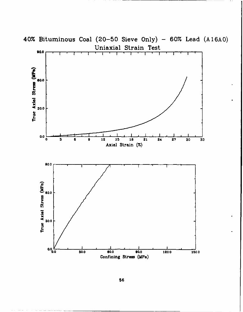
401 bituminous Coal - 60% Lead (A16AO)
Description: In an effort to raise the porosity, and, it washoped, lower the modulus, this specimen wasprepared with coal having appoxoimately uniformgrain sizes. All coal passed a No. 20 and wasretained on a No. 50 sieve. The lead was free flowlead shot.
Test Specimen: Dry Bulk Density (kg/m 3 ): 1786Porosity: .368
Test Results: Constrained Modulus (MPa): 39Poisson's Ratio: 0.35
Model Ratios: Density: 1.11Modulus: 0.105Length: 1/10.6
(Scale Factor)
Comments: The desired higher porosity was obtained, but itdid not result in the lower modulus. The initialmodulus was essentially the same as that measuredin test A12A0. This, combined with the lowerdensity, resulted in a slightly less desirablescale factor.
55
40% Bituminous Coal (20-50 Sieve Only) - 60% Lead (A16A0)Uniaxial Strain Test
Sao
*0 30.0
0.0o 3 0 9 12 15 18 21 24 27 30 33
Axial Strain (X)
90.0
S6100
Sao
30.0
0.0 30.0 0ao 00.0 120o0 150.0
Confining Stre (MPa)
56

APPENDIX C
DATA FROM THE STATIC PROOF-OF-PRINCIPLECONE PENETRATION TESTS
57
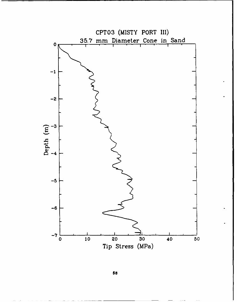
CPT03 (MISTY PORT III)
35.7 mm Diameter Cone in Sand
-1
-2
-3 -3
Q -4
-5
-6
-70 10 20 30 40 50
Tip Stress (MPa)
58

CPT 13 (MISTY PORT III)35.7 mm Diameter Cone in Sand
-2
-3 -3
Q -4
-5
-6
-710 10 20 30 40 50
Tip Stress (MPa)
59
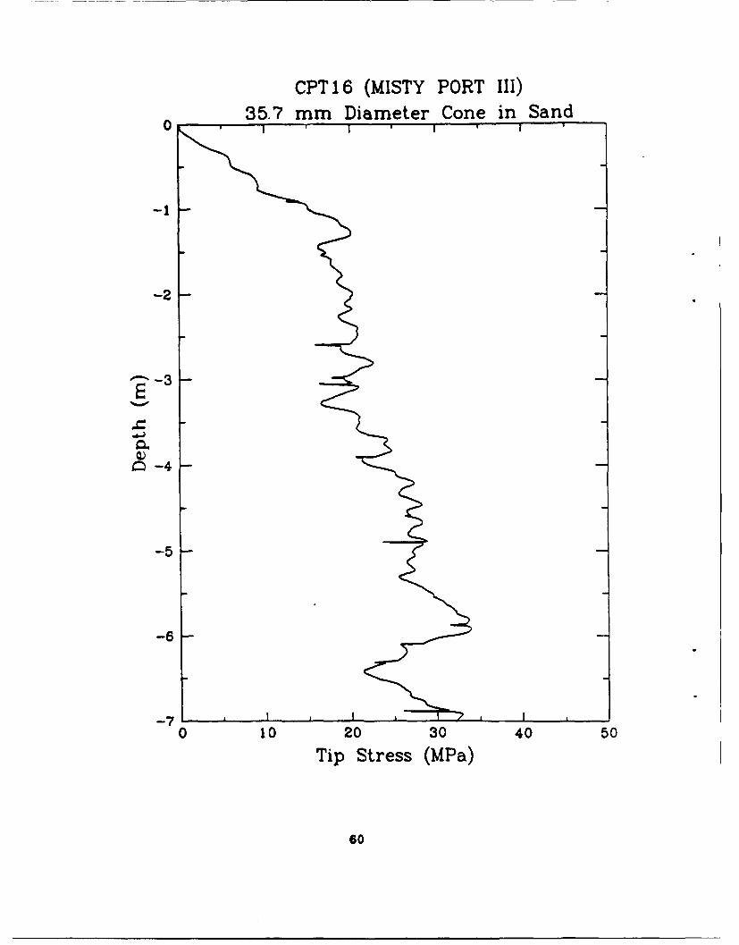
CPT 16 (MISTY PORT III)35.7 mm Diameter Cone in Sand
-2
- -3
C) -4
-5
-6
-7-0 10 20 30 40 50
Tip Stress (MPa)
60

CPT 17 (MISTY PORT III)35.7 mm Diameter Cone in Sand
-1
-2
Q -4
-5
-6
-70 10 20 30 40 50
Tip Stress (MPa)
61
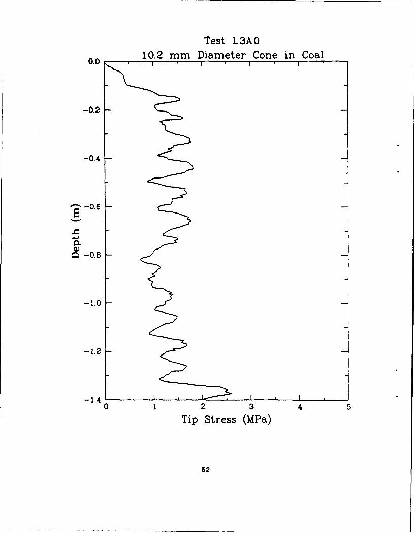
Test L3AO
10.2 mm Diameter Cone in Coal
-0.2
-0.4
" -0.6
a -0.8
-1.0
-1.2
-1.40 1 2 3 4 5
Tip Stress (MPa)
62

Test L3BO
10.2 mm Diameter Cone in Coal0.0I * ,
-0.2
-0.4
"• -0.8
-1.0
-1.2
-1.410 1 2 3 4 5
Tip Stress (MPa)
63

Test L5AO10.2 mm Diameter Cone in Coal
0.0 ' * I *
-0.2
-0.4
"' -0.6
M -0.8
-1.0
-1.2
-1.40 1 2 3 4 5
Tip Stress (MPa)
64
Test L5BO10.2 mm Diameter Cone in Coal
0.0 I * I '
-0.2
-0.4
"~ -0.6
a -0.8
-1.0
-1.2
-1.40 1 2 3 4 5
Tip Stress (MPa)
65
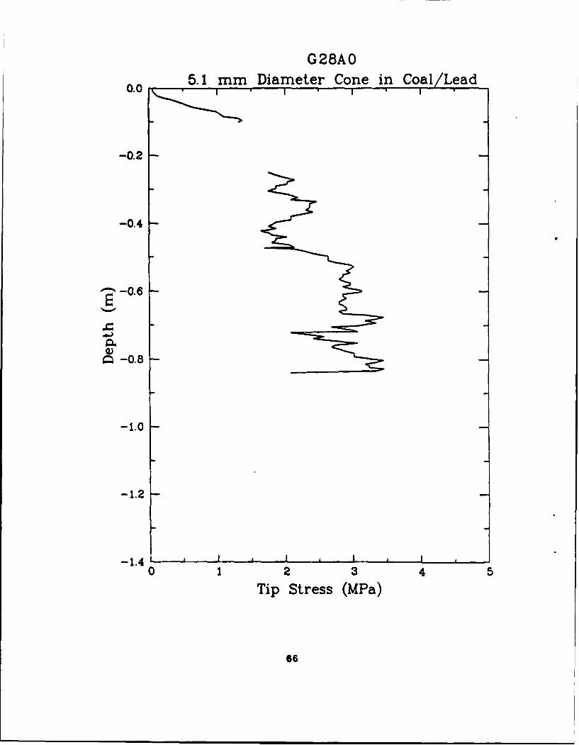
G28A0
5.1 mm Diameter Cone in Coal/Lead0.0 i i
-0.2
-0.4
"-0.6
Q -0.8
-1.0
-1.2
-1.4 I , I I0 1 2 3 4 5
Tip Stress (MPa)
66
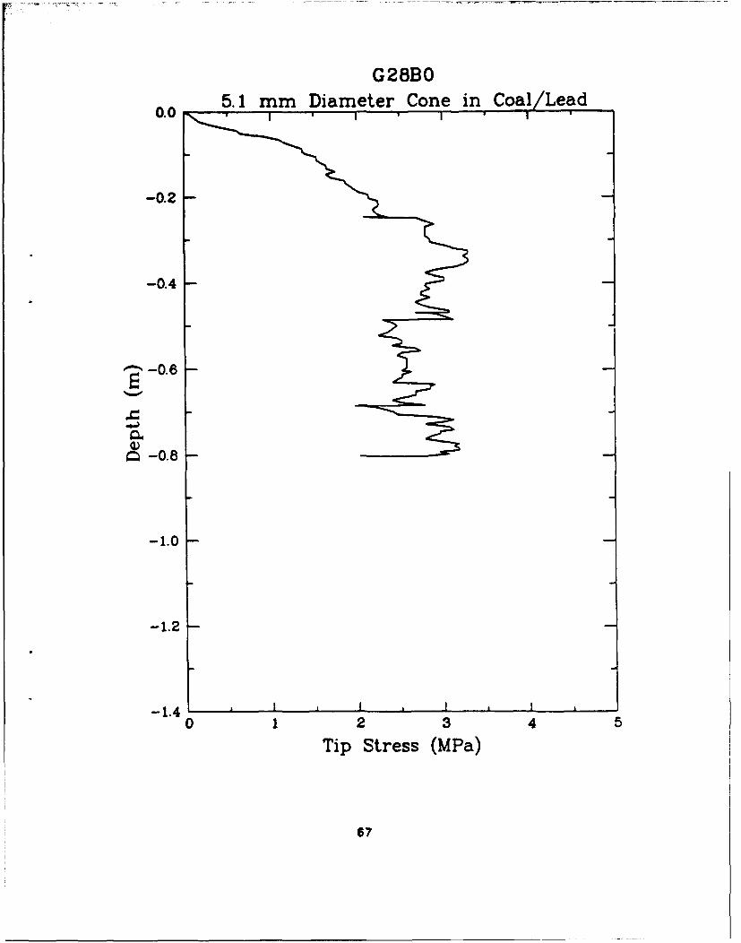
G28BO0.0 65.1 mm Diameter Cone in Coal/Lead
-0.2
-0.4
-0.6
Q -0.8
-1.0
-1.2
-1.410 1 2 3 4 5
Tip Stress (MPa)
67
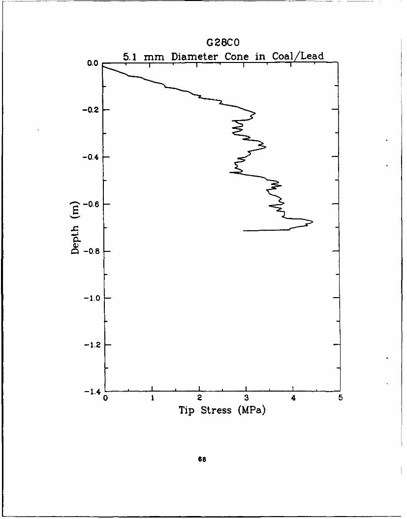
G28C05.1 mm Diameter Cone in Coal/Lead
-0.2
-0.4
"-• -0.6
c -0.8
-1.0
-1.2
- 1.4 I * I I ,0 1 2 3 4 5
Tip Stress (MPa)
68
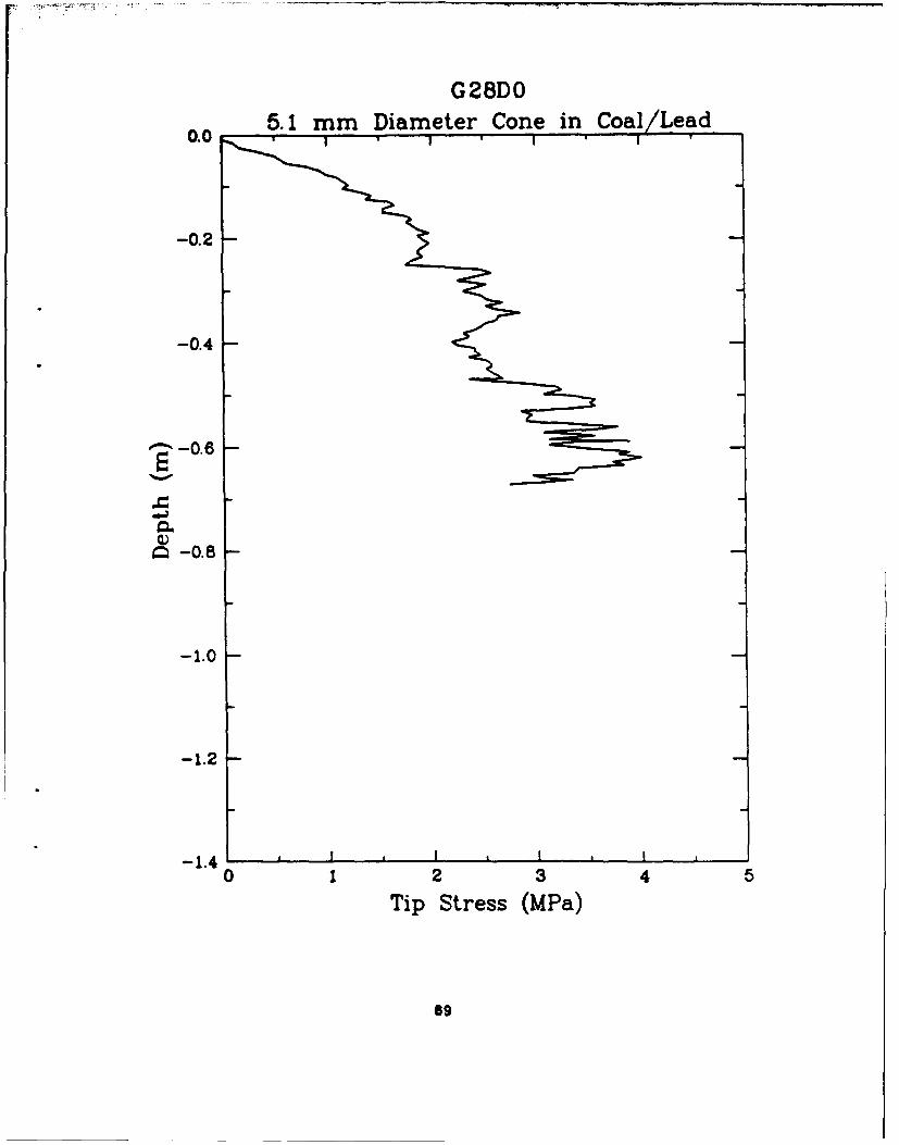
G28DO0.0 5.1 mm Diameter Cone in Coal/Lead
-0.2
-0.4
-086
I -0.8
-1.0
-1.2
-1.4 I , 1 , , I0 1 2 3 4 5
Tip Stress (MPa)
69
APPENDIX D
DYNAMIC CYLINDER TESTS
MEASUREMENT LISTSTEST LAYOUTS
PREDICTED VALUESTEST BED DENSITY MEASUREMENTS
70
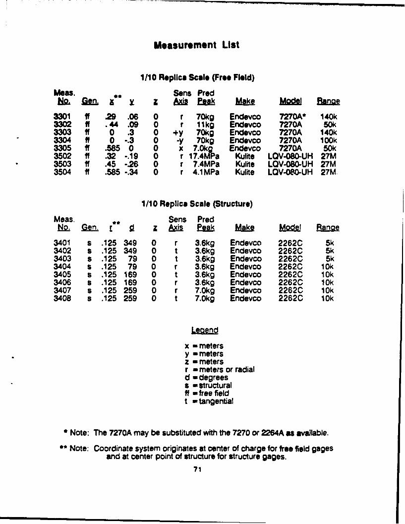
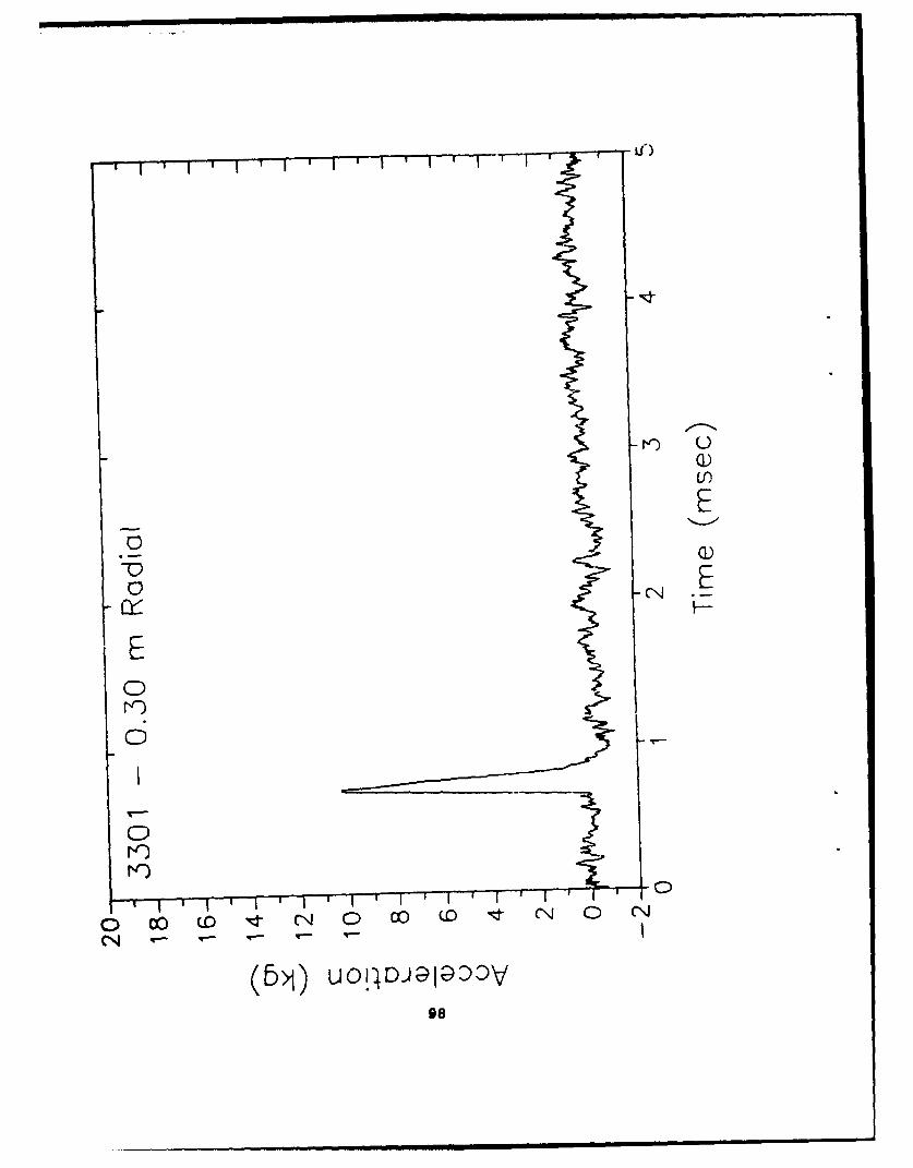
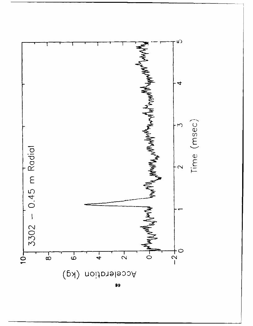
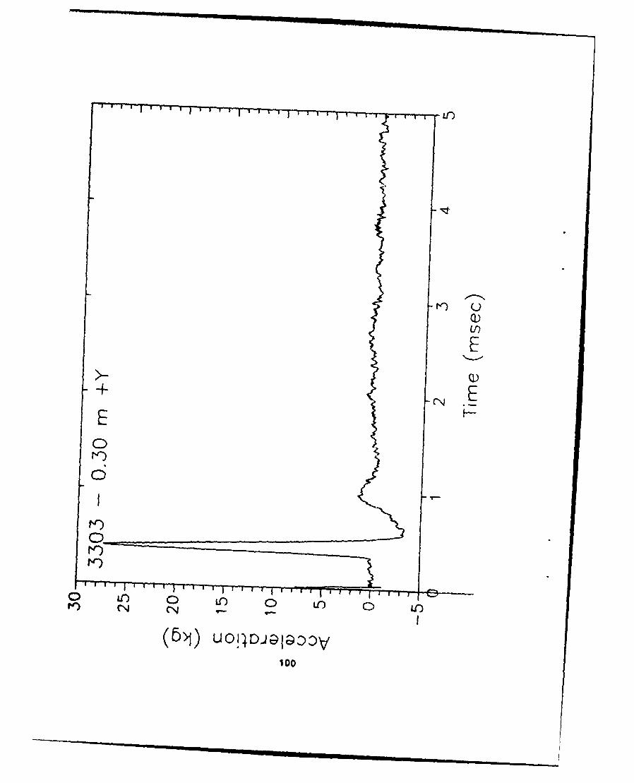
Measurement List
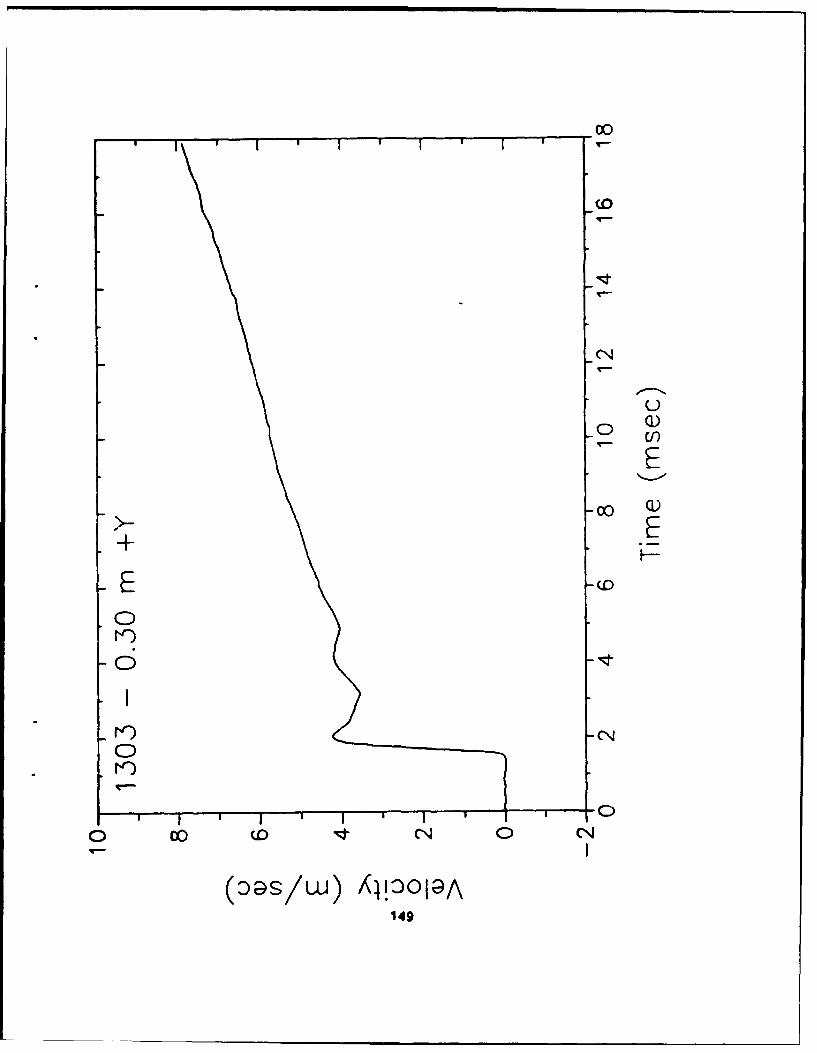
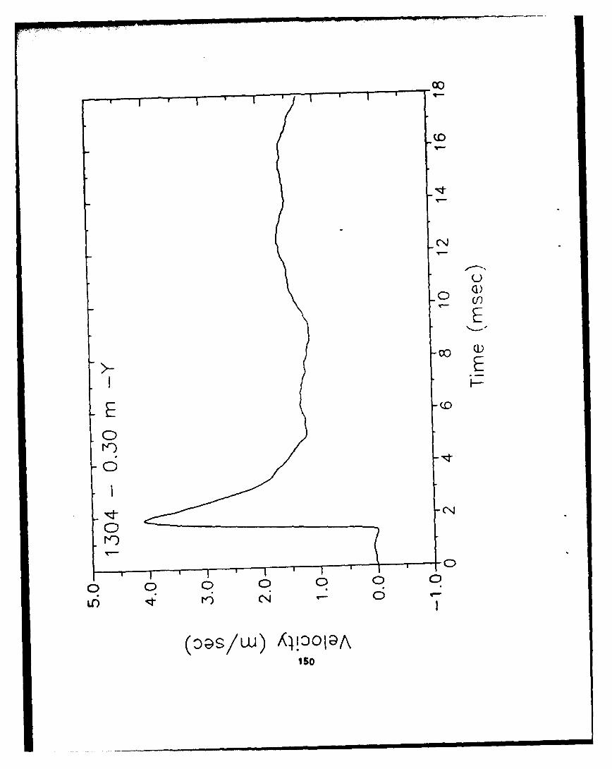
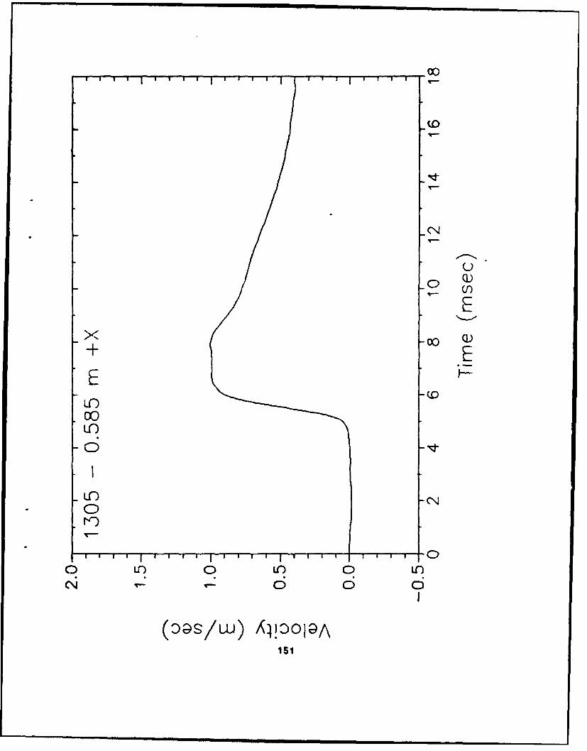
1/10 Replica Scale (Free Field)
Meas. Sons ProdL. eo X & A Mohe ftt
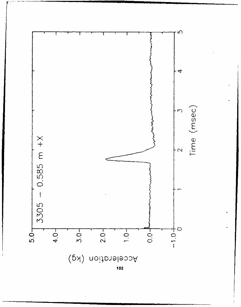
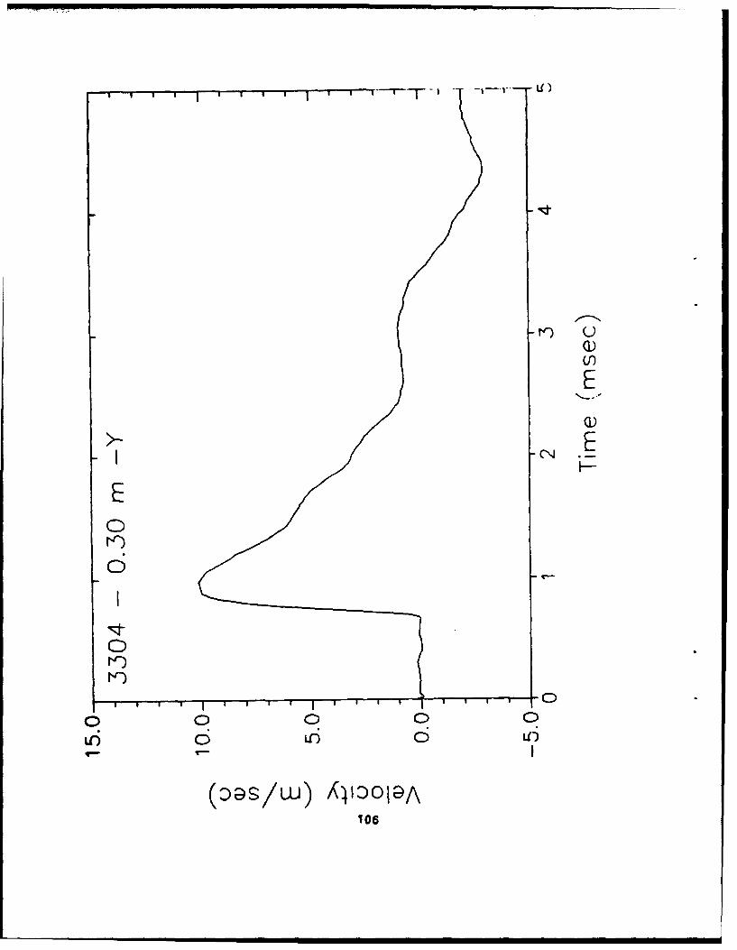
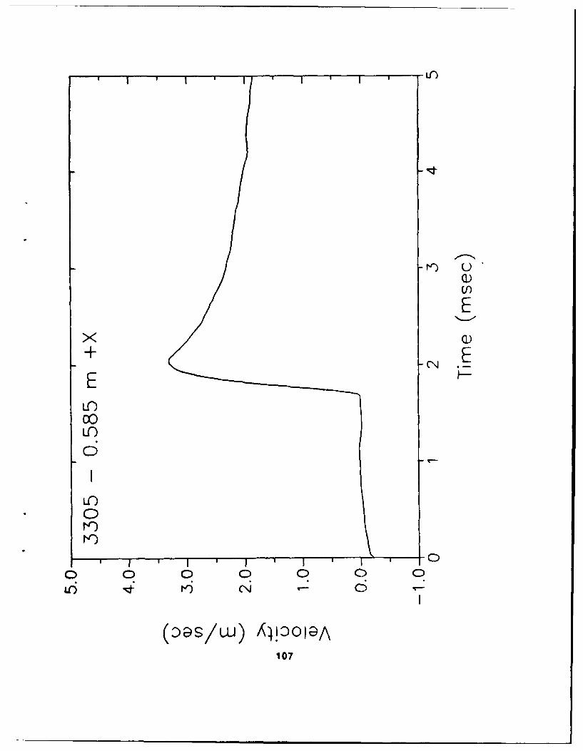
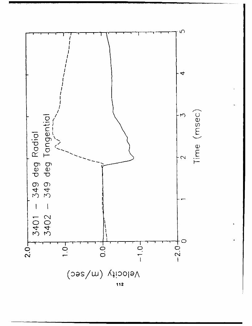
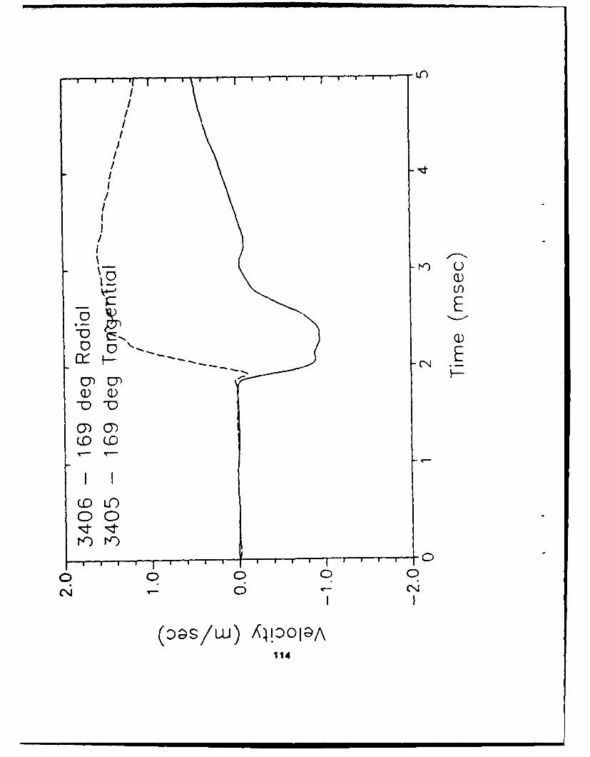
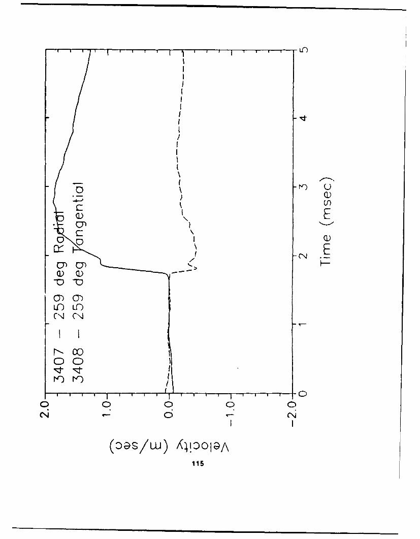
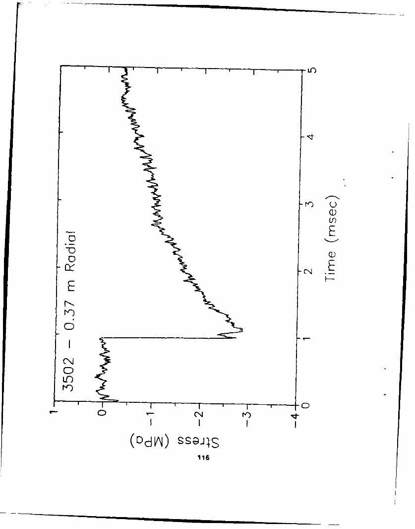
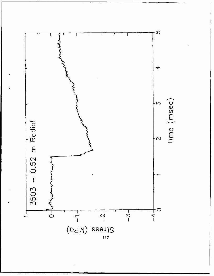
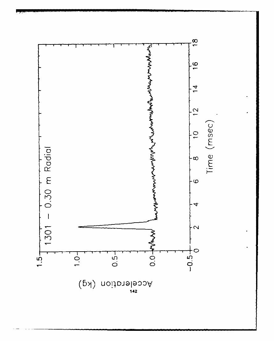
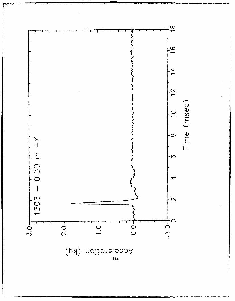
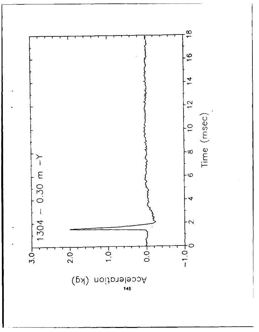
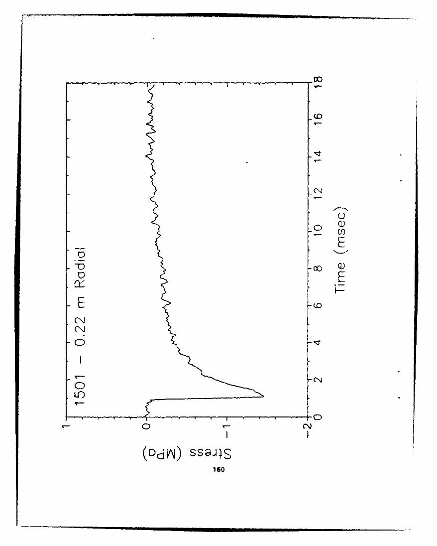
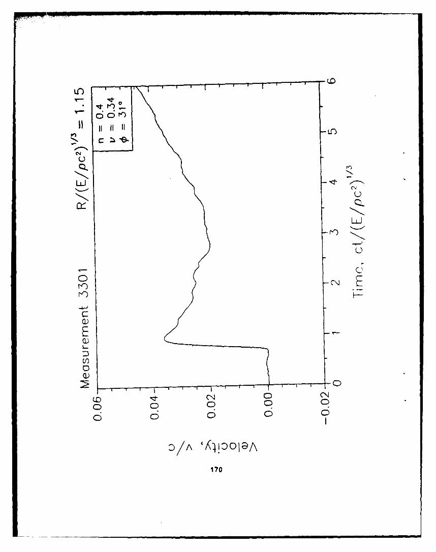
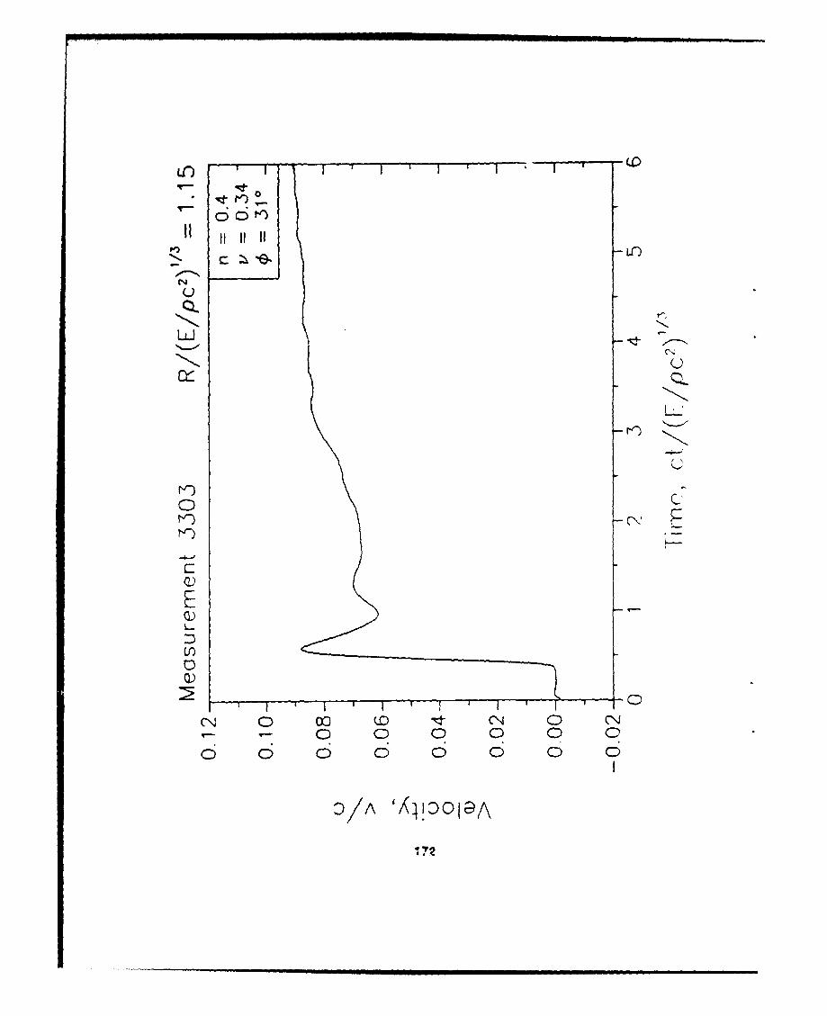
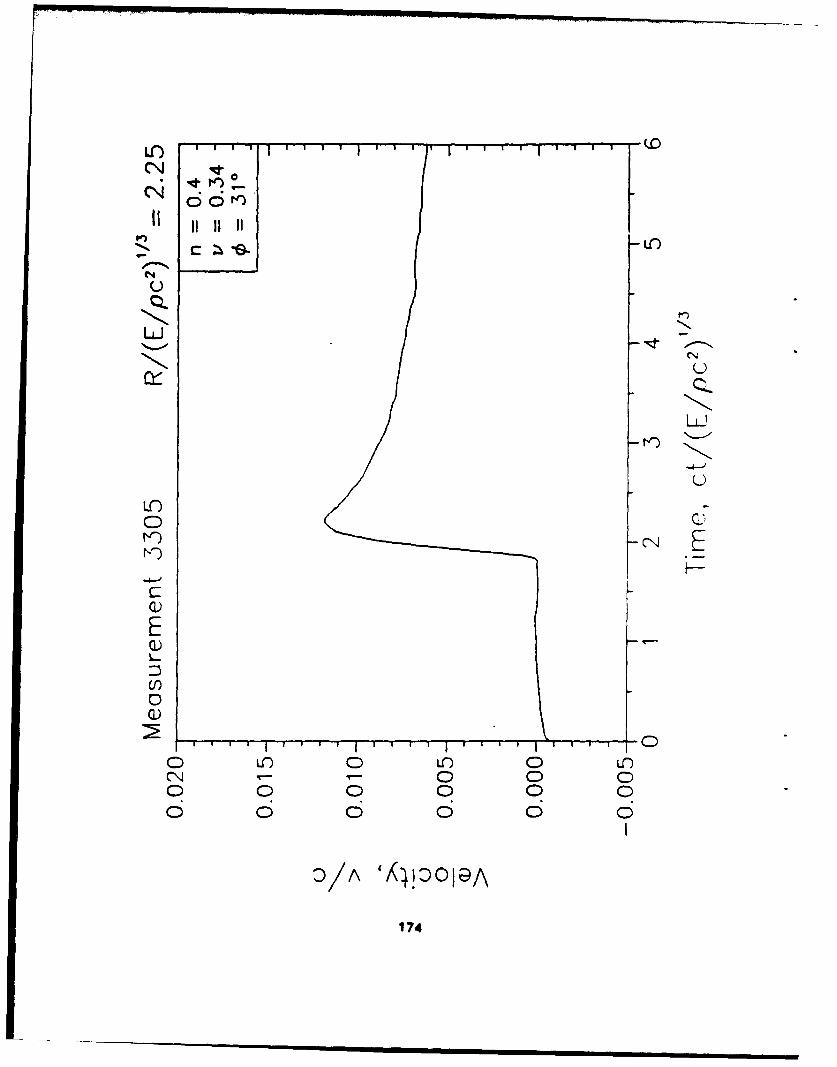
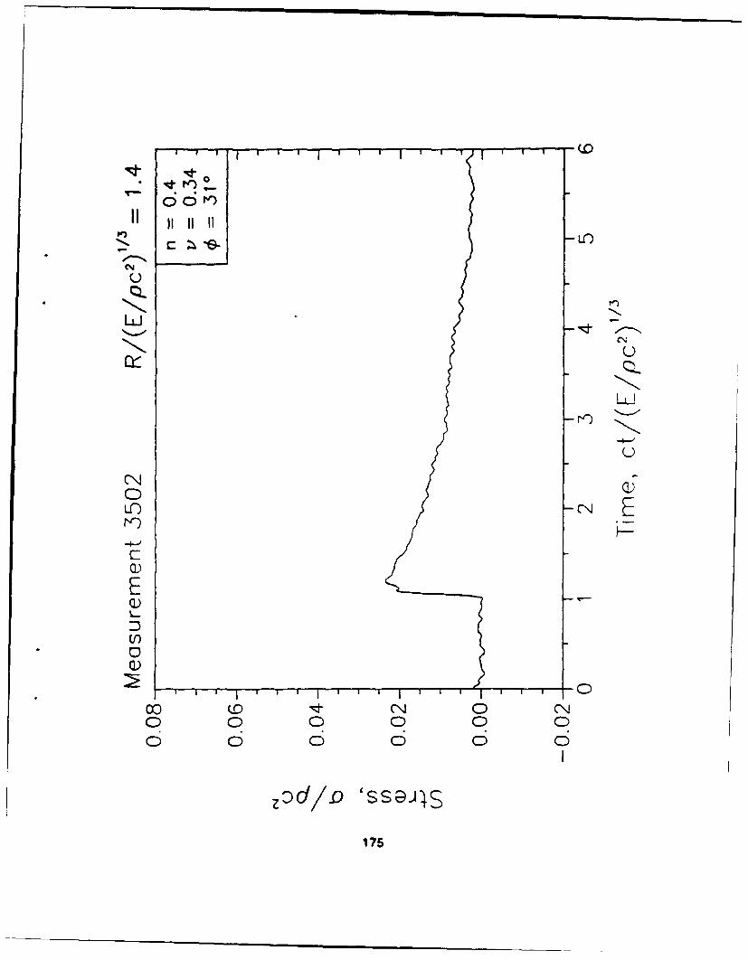
3301 If .29 .06 0 r 70kg Endevco 7270A* 140k3302 if .44 .09 0 r 11kg Encdevco 7270A 50k3303 if 0 .3 0 +y 70kg Endevco 7270A 140k3304 ff 0 -.3 0 -y 70kg Endeveo 7270A 100k3305 If .585 0 0 x 7.0kg Endovco 7270A 50k3502 If .32 -.19 0 r 17.4MPa Kulfte LOV-080-UH 27M3503 If .45 -.26 0 r 7.4MPa Kulite LOV-080-UH 27M3504 If .585 -.34 0 r 4.1 MPa Kulite LOV-080-UH 27M
1/10 Replica Scale (Structure)
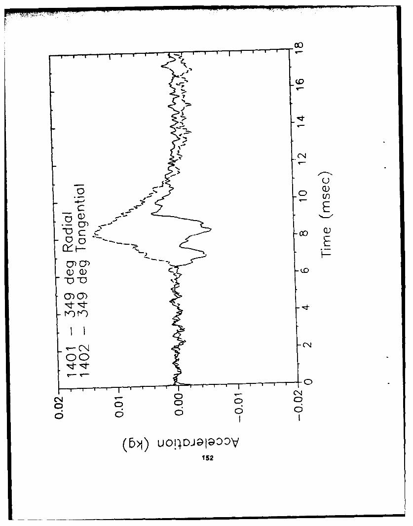
Meas. Sens ProdNo. 3 4 PEak 9kd Mode Range
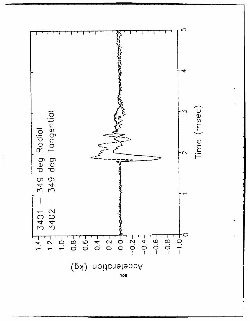
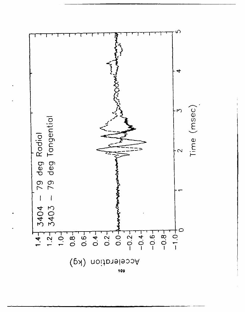
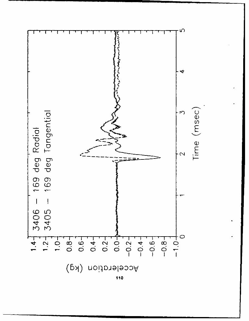
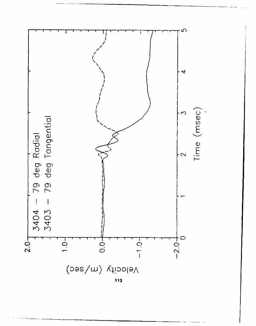
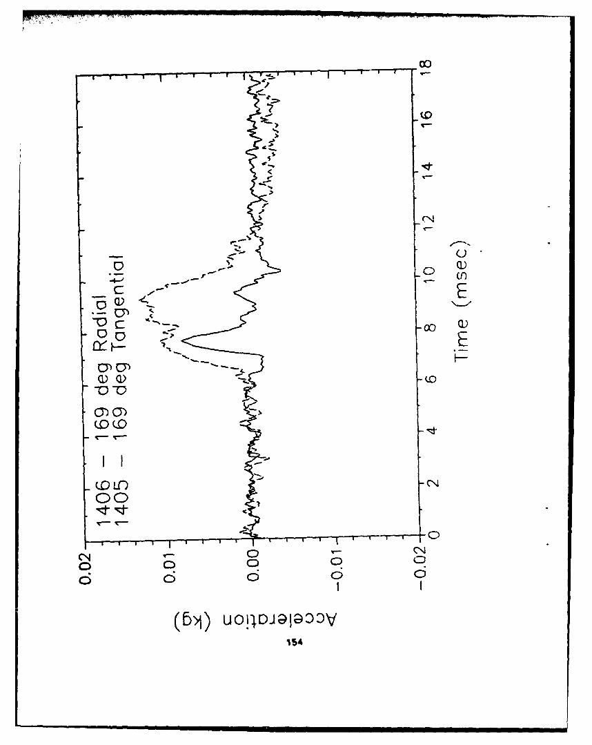
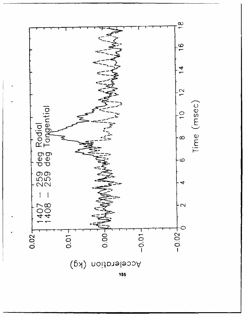
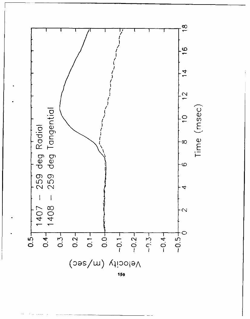
3401 s .125 349 0 r 3.6kg Endevco 2262C 5k3402 s .125 349 0 t 3.6kg Endevco 2262C 5k3403 s .125 79 0 t 3.6kg Endevco 2262C 5k3404 s .125 79 0 r 3.6kg Endevco 2262C 10k3405 s .125 169 0 t 3.6kg Endevco 2262C 10k3406 s .125 169 0 r 3.6kg Endevco 2262C 10k3407 s .125 259 0 r 7.0kg Endevco 2262C 10k3408 s .125 259 0 t 7.0kg Endevco 2262C 10k
Legend
x - metersy w metersz =metersr -meters or radiald =degreesa - structuralff -free fieldt - tangential
* Note: The 7270A may be substituted with the 7270 or 2264A as available.
* Note: Coordinate system originates at center of charge for free field gagesand at center point of structure for structure gages.
71

.2
0Y 10 1
1- 1/4- . V .CZ IAu2
-~~ ~ ~' 1/2"'
q Lq
CC
113/451/4
72
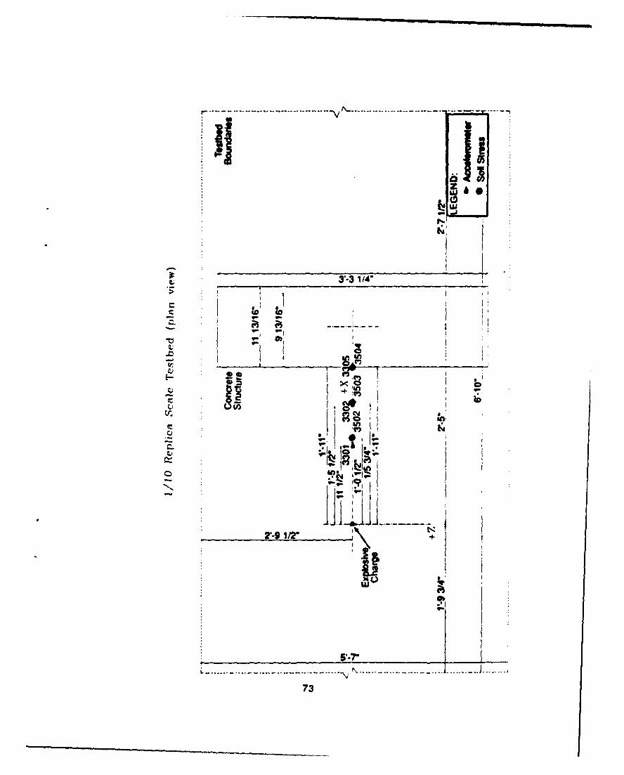
•r,% ......
als
t 3T-3 1/4"
C--
.0 r.. .
Anil
r"-9 1/2" *l\'
73
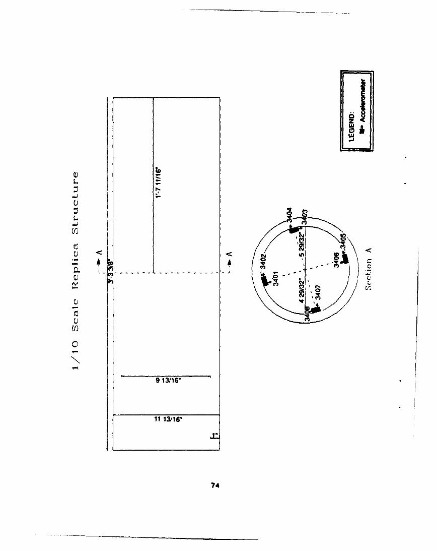
-J'
Q)L
0 s
r) gCV)
9 13/16"
11 13/16'
74
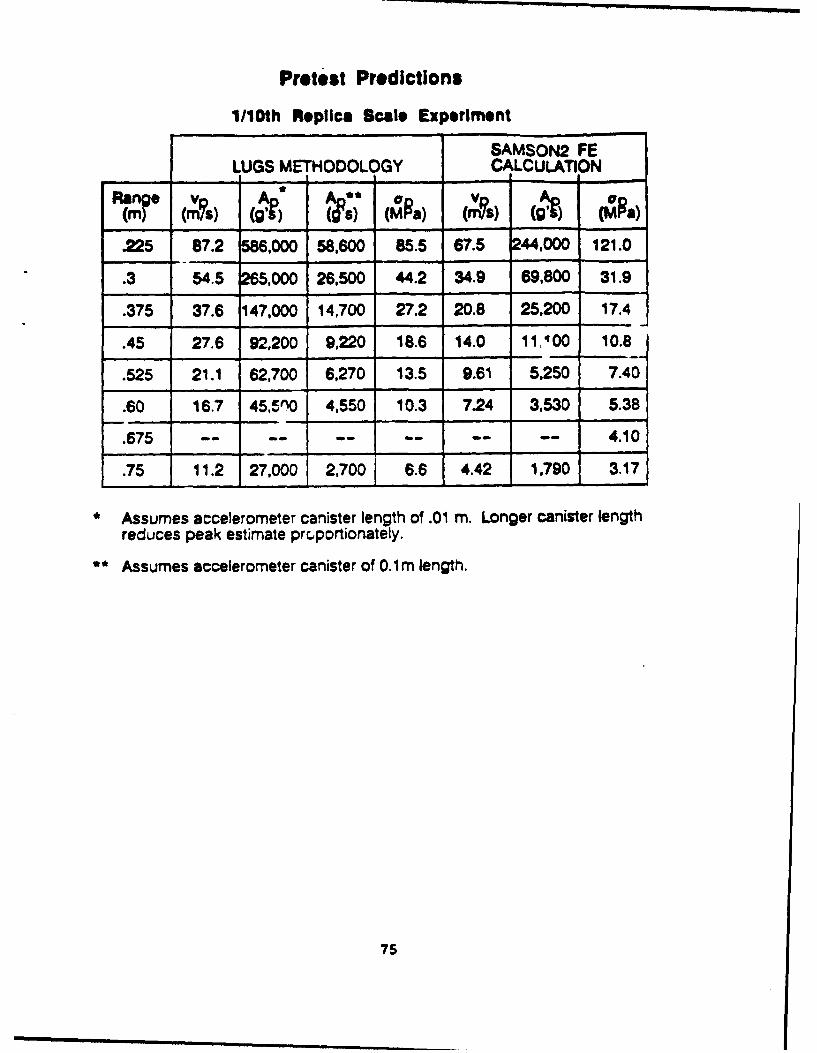
Pretest Predictions
1/10th Replica Scale Experiment
SAMSON2 FELUGS METHODOLOGY CALCULATION
Range v Aa A o
.225 87.2 586,000 58,600 85.5 67.5 244,000 121.0
.3 54.5 265,000 26,500 44.2 34.9 69,800 31.9
.375 37.6 147,000 14,700 27.2 20.8 25,200 17.4
.45 27.6 92,200 9,220 18.6 14.0 11 400 10.8
.525 21.1 62,700 6,270 13.5 9.61 5,250 7.40
.60 16.7 45,5n0 4,550 10.3 7.24 3,530 5.38
.675 -.......- -- 4.10
.75 11.2 27,000 2,700 6.6 4.42 1,790 3.17
• Assumes accelerometer canister length of .01 m. Longer canister lengthreduces peak estimate pr.portionately.
Assumes accelerometer canister of 0.1m length.
75
- - -Luu 0
zoo 0
L.
4m~
N -0 - -N E9
ra)-a)ý -o -f4 -; o '.
f" C)
w Dv
a E ol 01 - -- ~t0 LI
'~ON --
Z:
76
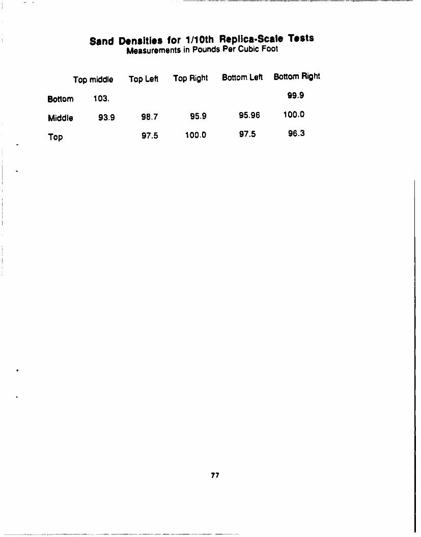
Sand Densities for 1/10th Replica.Scale TestsMeasurements in Pounds Per Cubic Foot
Top middle Top Left Top Right Bottom Left Bottom Right
Bottom 103. 99.9
Middle 93.9 98.7 95.9 95.96 100.0
Top 97.5 100.0 97.5 96.3
77

Me surement List
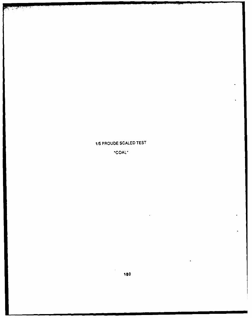
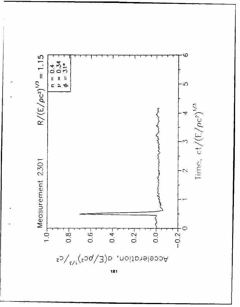
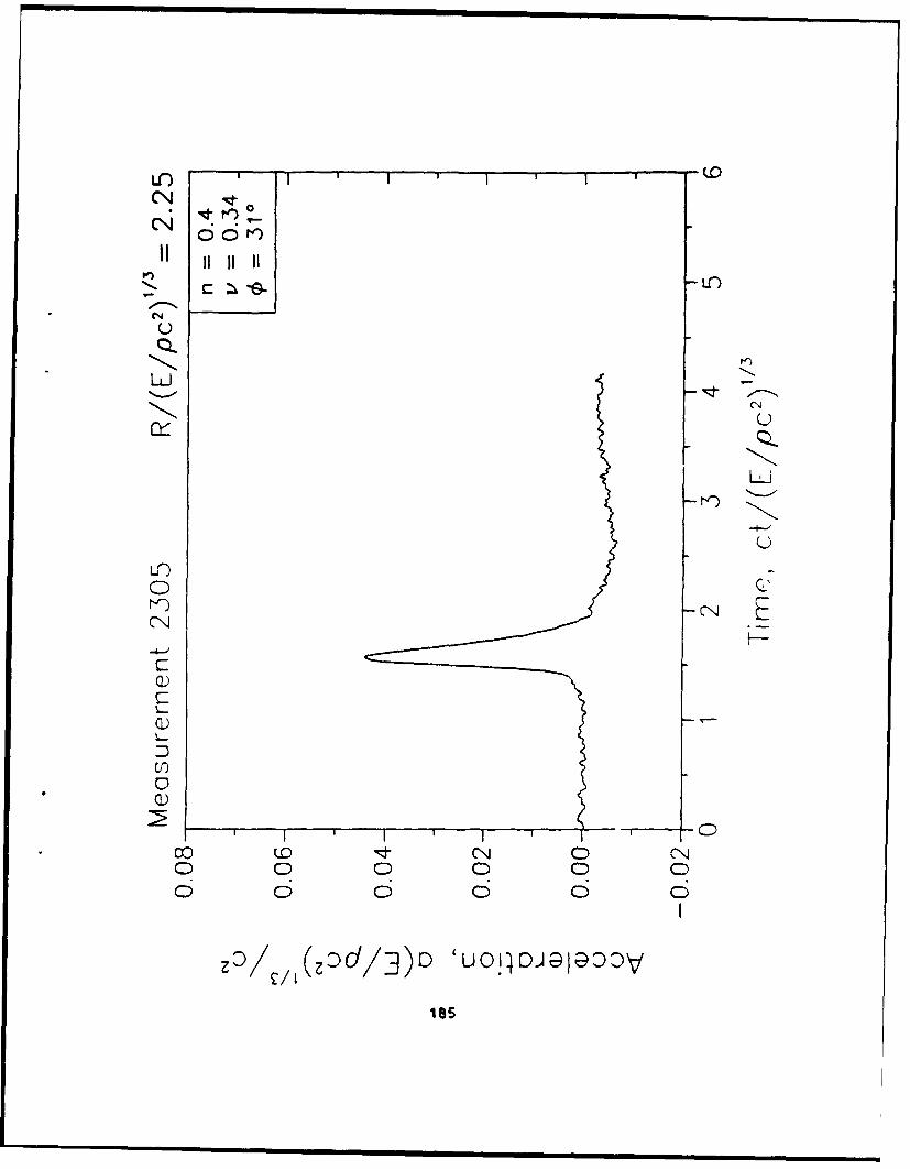
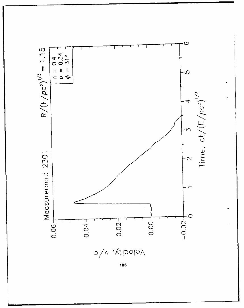
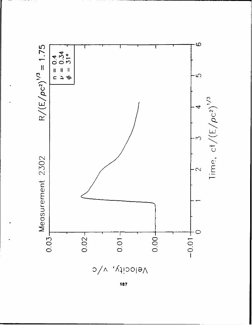
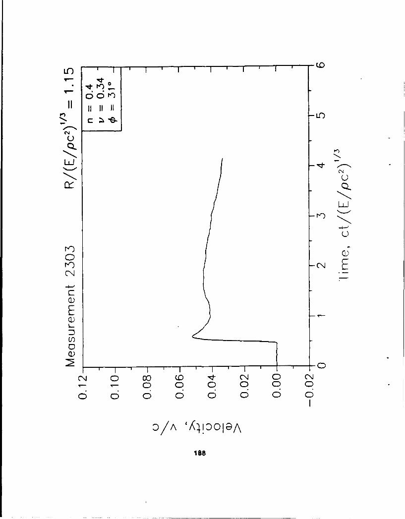
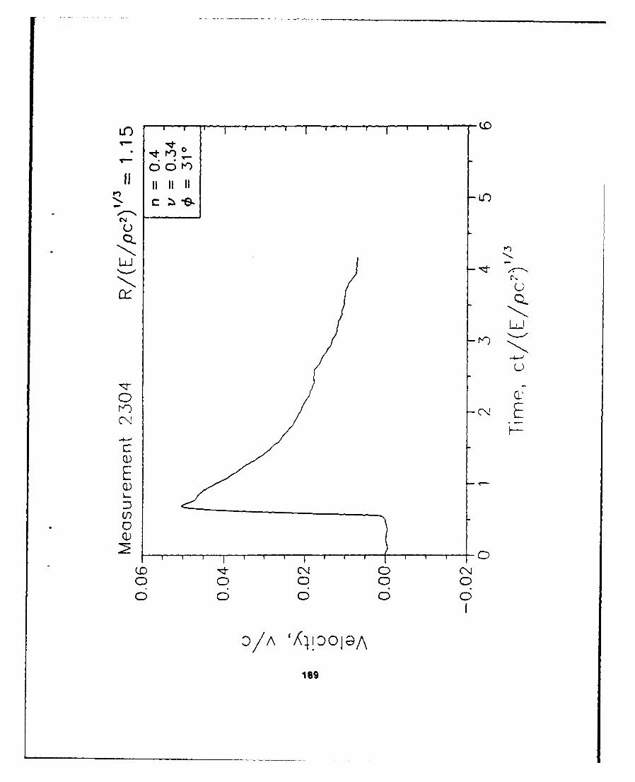
1/5 Froude Scale (Free Field)
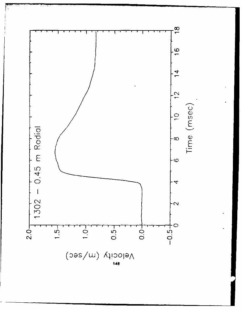
Meas. Sons ProdN2. A•x. A? P.k Make Model Rance
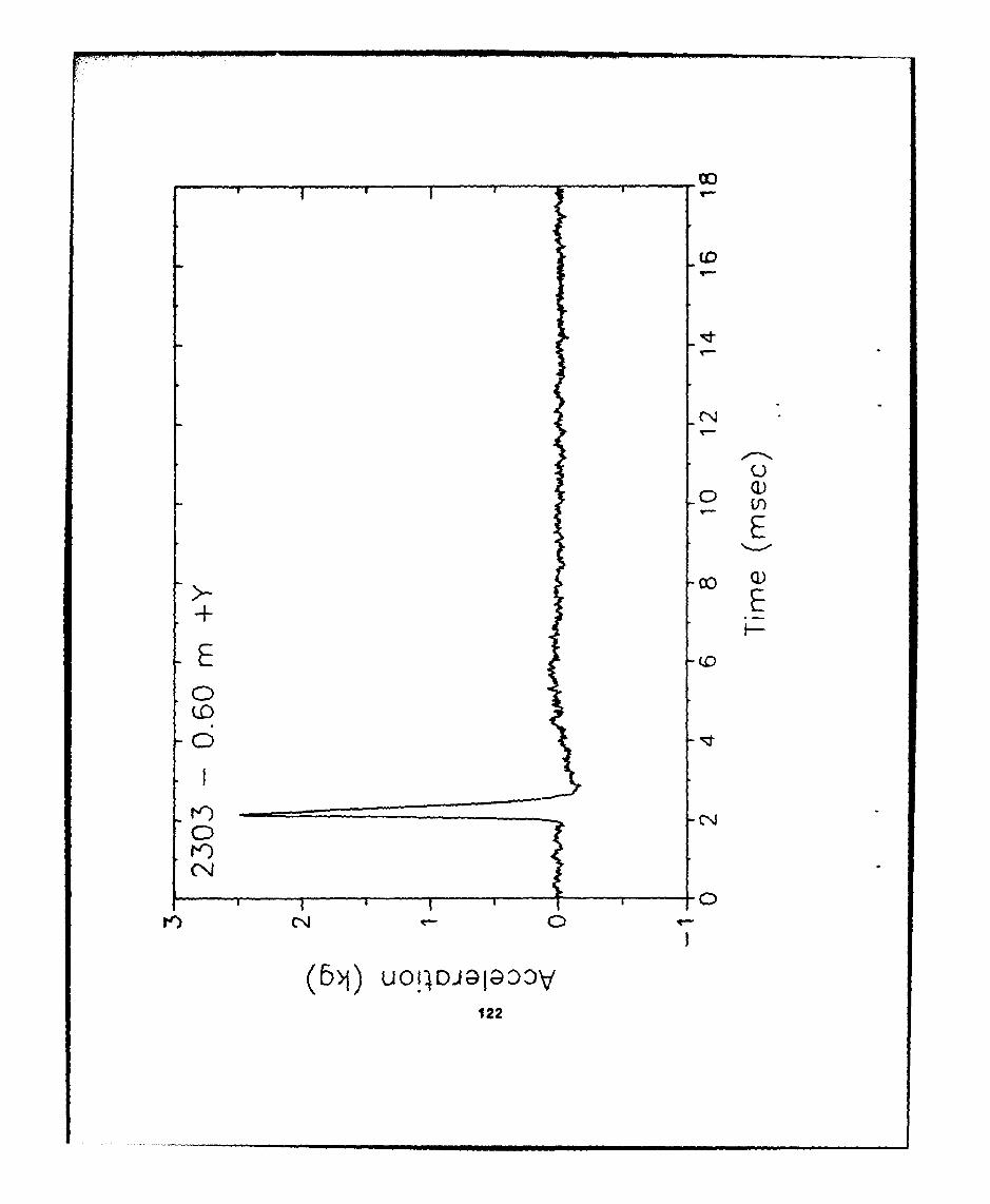
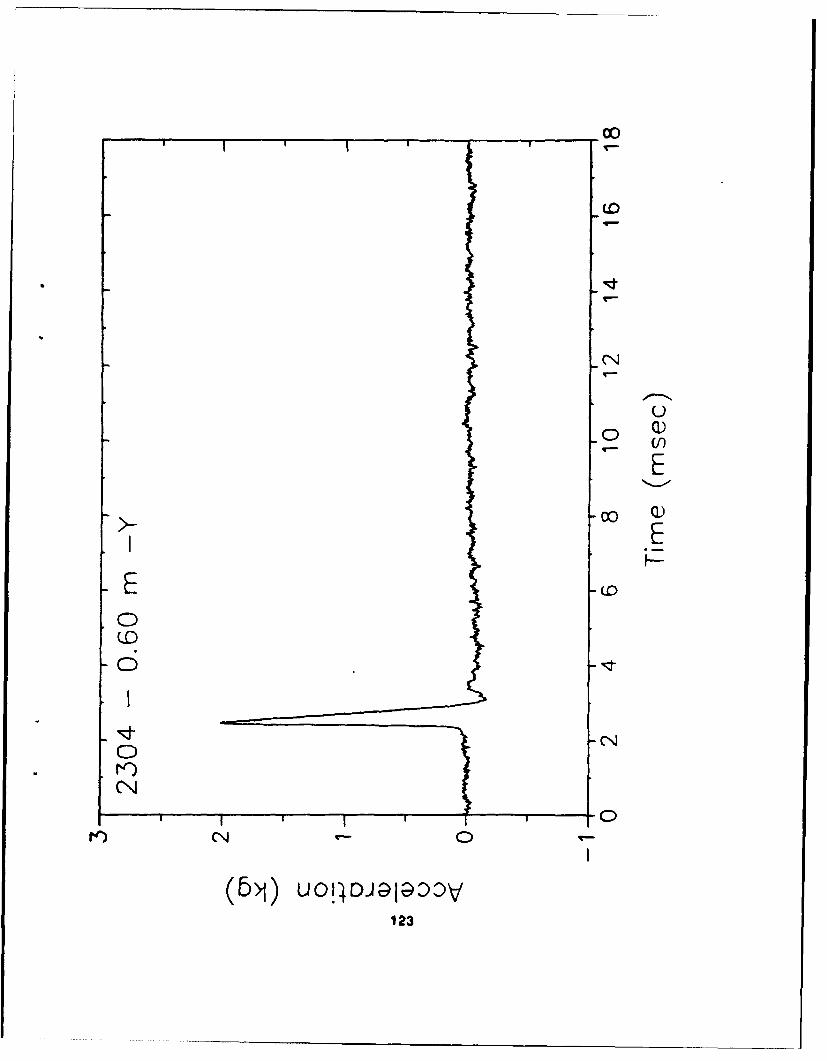
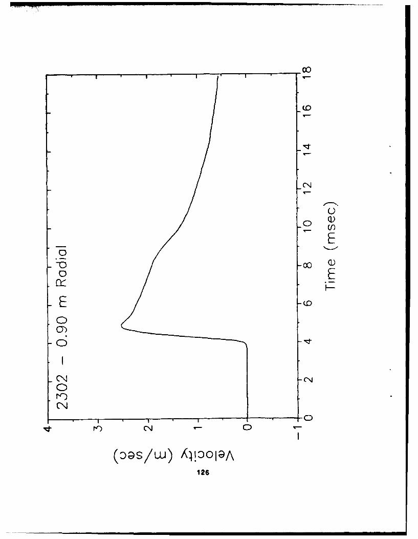
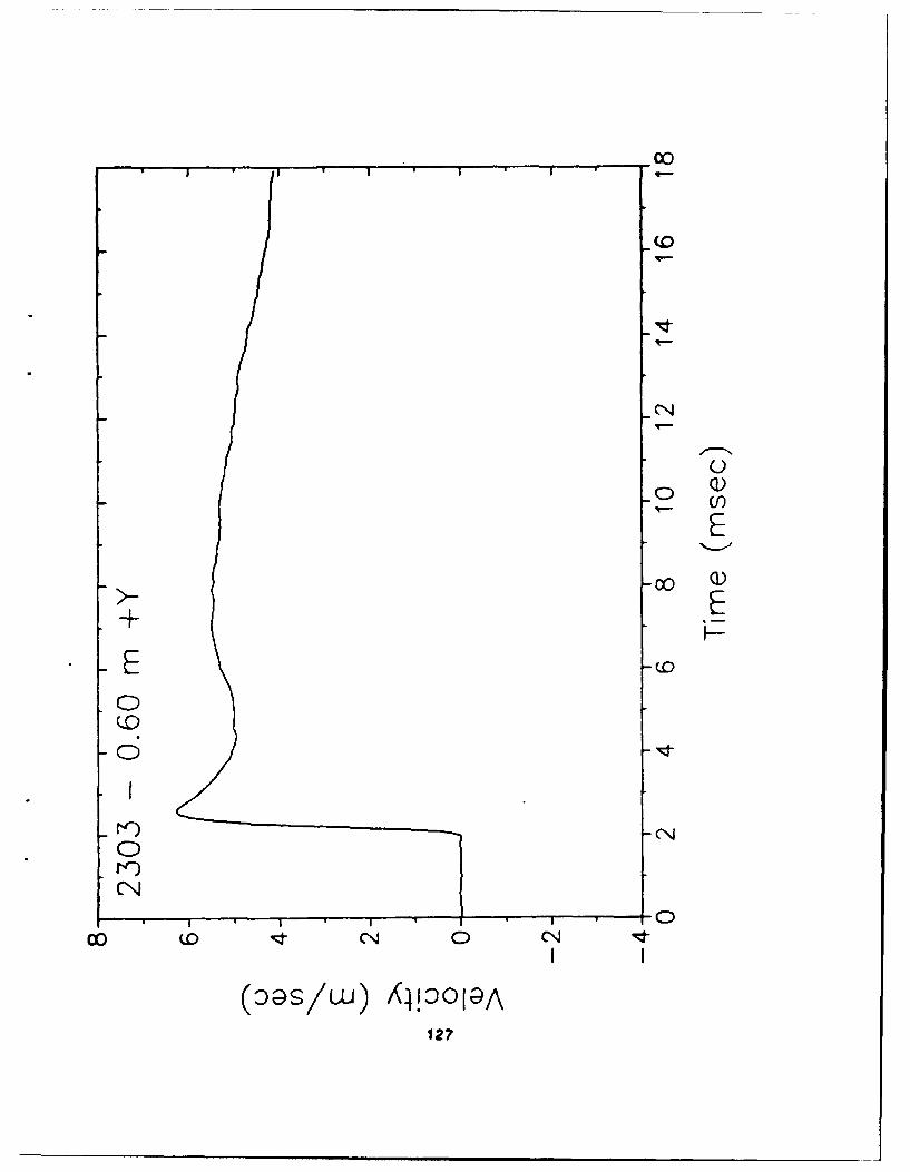
2301 ff .59 .12 0 r 6.9kg Endevco 7270A* 10k2302 f .88 .18 0 r 1.1kg Endevco 7270A 2k2303 ff 0 .6 0 +y 6.9kg Endevco 7270A 10k2304 ff 0 -.6 0 -y 6.9kg Endevco 7270A 10k2305 0 f 1.17 0 0 x 7069 Endevco 7270A 5k2501 if .39 -.23 0 r 12.1MWa Kulite LOV.OB0-UH 27M2502 ff .65 -.38 0 r 1.74MPa Kulite LQV-080-UH 27M2503 ff .91 -.53 0 r 0.74MPa Kulite LOV-080-UH I.4M
1/5 Froude Scale (Structure)
No Gen. ** S Z Axis Peak Make Model Bange
2401 s .25 349 0 r 360g Endevco 2262C 1k2402 s .25 349 0 t 360g Endevco 2262C 1k2403 s .25 79 0 t 360g Endevco 2262C lk2404 s .25 79 0 r 360g Endevco 2262C 1k2405 s 25 189 0 t 360g Endevco 2262C 1k2406 s .25 169 0 r 360g Endevco 2262C 1k2407 s .25 259 0 r 706g Endevco 2262C 1k2408 s .25 259 0 t 706g Endevco 2262C 1k
Lecend
x =metersy w metersz -metersr = meters or radiald :degreess ,structuralff =free fieldt - tangential
Note: The 7270A may be substituted with the 7270 or 2264A as available.
' Note: Coordinate system originates at center of charge for free feld gagesand at center point of structure for structure gages.
78

-J S.
C.C.,
9 (12"ji~Z~NY
91I2Y
Iv-
- &- -[II 3w
2* 4'112I
L Il i /- X -112
I ('2
W-1 Knq-Iiu 79

!llr% - -- -J
iti
w Opnon
S0 0
2 ,
m• to.
os
5'-6 1/2" '
w
11".1° .1 .L .. . . . . . . . . . ,-./ - . . . . . . . . . .. .-
s0
C.)Y
-CY
0cNYI
CCD
Pretest Predictions
1/Sth Froude Scale Experiment
SAMSON2 FELUGS METHODOLOGY CALCULATION
Range v AOS _ A a
.45 39.0 58,600 11,000 8.55 30.2 24,400 12.1
.60 24.4 26,500 5,200 4.42 15.6 6,980 3.19
.75 16.8 14,700 3,000 2.72 9.30 2,520 1.74
.90 12.3 9,220 24000 1.86 6.26 1,110 1.08
1.05 9.44 6,270 1,200 1.35 4.30 525 .74
1.20 7.47 4,550 900 1.03 3.24 353 .54
1.50 5.01 2,700 500 .66 1.98 179 .32
Assumes accelerometer canister length of .02 m. Longer canister lengthreduces peak estimate proportionately.
Assumes accelerometer canister of 0.1m length and somewhat less dense(t 1/2) than "standard".
82

Coal Densities In 1/5 Frouds Test
These are the coal density measurements (lb/cuft) recorded by Larry Smith for the 1/5th scaleFroude test.
DEPTH NW NE SE SW CENTER(in) Comer Corner Corner Corner (1)
9 55.4(2) - - 51.4(2)12 52.6 51.2 51.0 50.8 52.826 50.7 54.9 54.9 53.5 55.933 53.4 54.8 52.4 54.1 56.948 53.9 51.9 52.7 54.2 53.8
33 50.4 at edge of structure where coal was compacted by hand using a rolling pin.
Note 1: The measurements in the CENTER column were taken at the center of the pit at the48" depth. Samples at the other depths were taken 6' from the east wall of the pit tokeep clear of the structure. All samples were taken at a point 4 from the north pitwall.
Note 2: The density measurements at 9" depth were in the coarser coal used to fill in at theedges of the pit.
All corner measurements were taken 30" from each wall, except for those at 9" which were taken at 20"from the west wall so as to remain clear of the fine coal in the center of the pit.
83

Measurement Ust
1/10 Froude Scale (Free Field)
Moas. Sens ProdU9. Geln. I**X I ji Peak Make Model Rn
1301 if .29 .06 0 r 6.9kg Endevco 7270A* 10k1302 if .44 .09 0 r 1.1kg Endvco 7270A 2k1303 if 0 .3 0 +y 6.9kg Endevco 7270A 10k1304 ff 0 -.3 0 -y 6.9kg Endevco 7270A 10k1305 If .585 0 0 x 706g Endevco 7270A 5k1501 if .19 -.11 0 r 12.1 MWa Kulite LOV-080-UH 27M1502 If .32 -.19 0 r 1.74MPa Kulite LOV-080-UH 27M1503 f .45 -.26 0 r 0.74MPa Kulite LOV-080-UH 1.4M
1/10 Froude Scale (Structure)
Meas. Sens PredNo . ** G Z Axis Peak Make Mode Rang
1401 s .125 349 0 r 360g Endevco 2262A 1k1402 s .125 349 0 t 360g Endevco 2262A 1k1403 s .125 79 0 t 360g Endevco 2262A 1k1404 s .125 79 0 r 360g Endevco 2262A 1k1405 s .125 169 0 t 360g Endevco 2262A 1k1406 s .125 169 0 r 360g Endevco 2262A 1k1407 s .125 259 0 r 706g Endevco 2262A lk1408 s .125 259 0 t 706g Endevco 2262A 1k
Leoend
x =metersy = metersz -metersr -a meters or radiald =degreess - structuralIf -free fieldt w tangential
Note: The 7270A may be substituted with the 7270 or 2264A as available.
* Note: Coordinate system originates at center of charge for free field gages
and at center point of structure for structure gages.
84
• 4 3/4"
N1 1/4' LO b
1/0
V-4 /2 " -314
**12
11 ~3/4" 101 /4" 1
- '-. '-4 11 4 "~
X0
3 -5 ime___
S....................................
ii oil
"•' 3'T-3 114" •
U,. i i 7
w • z@I,.,.
CC'
2'-9 1/2" , ,
-, -
~D 11A
5-- I
86

0)03- w
C3
00
1; 87

Pretest Predictions
1/10th Frouds Scale Experiment
SAMSON2 FELUGS METHODOLOGY CALCULATION
MI (r,) * M
•25 27.6 58,600 5,880 8.55 21.3 24,400 12.1
.3 17.2 26,500 2,650 4.42 11.0 6,980 3.19
.375 11.9 14.700 1,470 2.72 6.58 2,520 1.74
.45 8.73 9.220 920 1.86 4,43 1,110 1.08
.525 6.67 6.270 620 1.35 3.04 525 .74
.60 5.28 4,550 455 1.03 2.29 353 .54
.75 3.54 2,700 270 .86 1.40 179 .32
* Assumes accelerometer canister length of .01 m. Longer canister lengthreduces peak estimate proportionately.
Assumes accelerometer canister of 0.1m length.
68
Coal/Lead Densities in 1/10 Froude-Scale Test
These are the o,,'eaKd mixture density measurements (pb/cutt) recorded by Larry Swdth for the 1/10thWcale Froude test. All comer measurements were taken 18" from each wall.
DEPTH SW NW NE SE CENTER(in) Corner Corer Corner Comer (1)
S 160' 110 - 108 10016 100 130" 107 105 -20 137"" 134"" 142"" 137"" -28 131 109 116 126 11433 115 - 107 - 1144 (from bottom) - 82 120 - -
CoaVlead mixture was dumped from the mixer into this comer of the ph, and considerable weightaccumulated above this sample before the mixture was spread out to the rest of the ph.
There was a great deal of foot traffic in the pit comers prior to removing these samples, whichseems to have compacted the mixture in these samples. After these high readings were taken,foot traffic in the pit was avoided as much as possible to prevent such compaction. The crewalways avoided walking in the center of the pit (between charge and structure) so the mixture wasprobable not compacted as much in this area.
"No explanation for this high reading.
The coa~lead mixture tended to separate whenever it was disturbed, with lead going to the bottomThis was observed when it was poured from the mixer into the pit, or when it was shoveled from onepoint to another. Whether this could account for some of the variation in the readings is not clear.
89
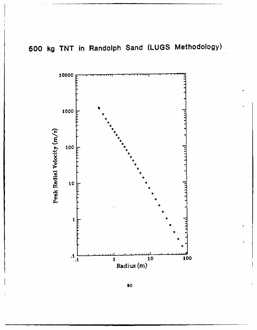
500 kg TNT in Randolph Sand (LUGS Methodology)
10000.
1000
Ob
S100 0
100
0
N 0
I• 100 00.
90
V 0
9- 0
0
.1
.1 1 10 100
Radius (in)
so
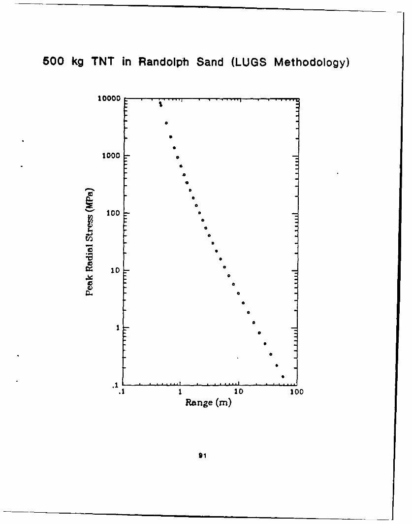
500 kg TNT in Randolph Sand (LUGS Methodology)
10000 T ~J w| • •••wf
1000 • °-
•" 100 0*-
a) °
S10 • .
• °o
So0
0
o
0
I0
S
S
.1 11 0
Range (in)
*1
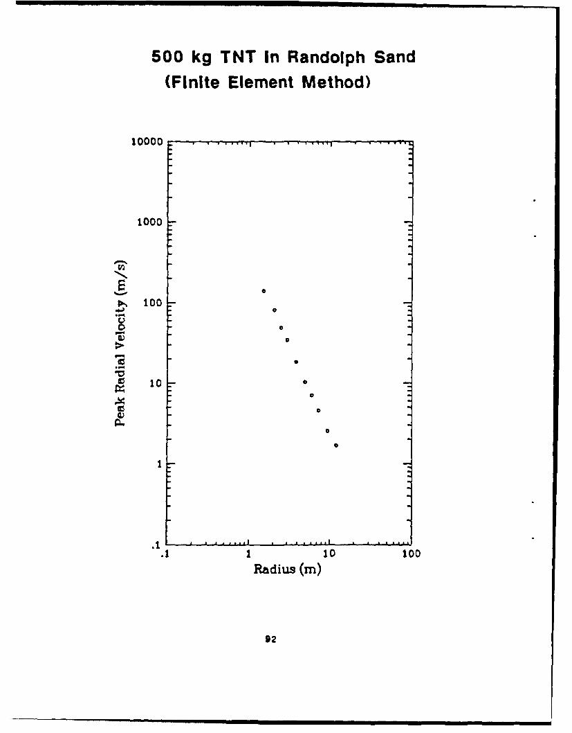
500 kg TNT In Randolph Sand
(Finite Element Method)
10000
1000
S1000
0 I0
1 10 100
Radius (m)
92
0ia e ]g

500 kg TNT In Randolph Sand(Finite Element Method)
10000
1000
10
11. 1.10 10
SI100
93
o~~c 8
CL
k I
6D)C
C V-4~ILO~~~~~ (ut)I'uailsC
I'4I

Prediction for 500 kg TNT In Randolph Sand
SAMSON2 FELUGS METHODOLOGY CALCULATION
Rane (s A______ ____(~ MA) (ms) ) (M'Pa)
2.25 87.2 58,600 85.5 67.5 24,400 121.0
3.0 54.5 26,500 44.2 34.9 6,90 31.9
3.75 37.6 14,700 27.2 20.8 2,520 17.4
4.5 27.6 9,220 18.6 14.0 1,110 10.8
5.25 21.1 6,270 13.5 9.61 525 7.40
6.0 16.7 4,550 10.3 7.24 353 5.38
7.5 11.2 2,700 6.6 4.42 179 3.17
"Assumes accelerometer canister length of 0.1 m
95

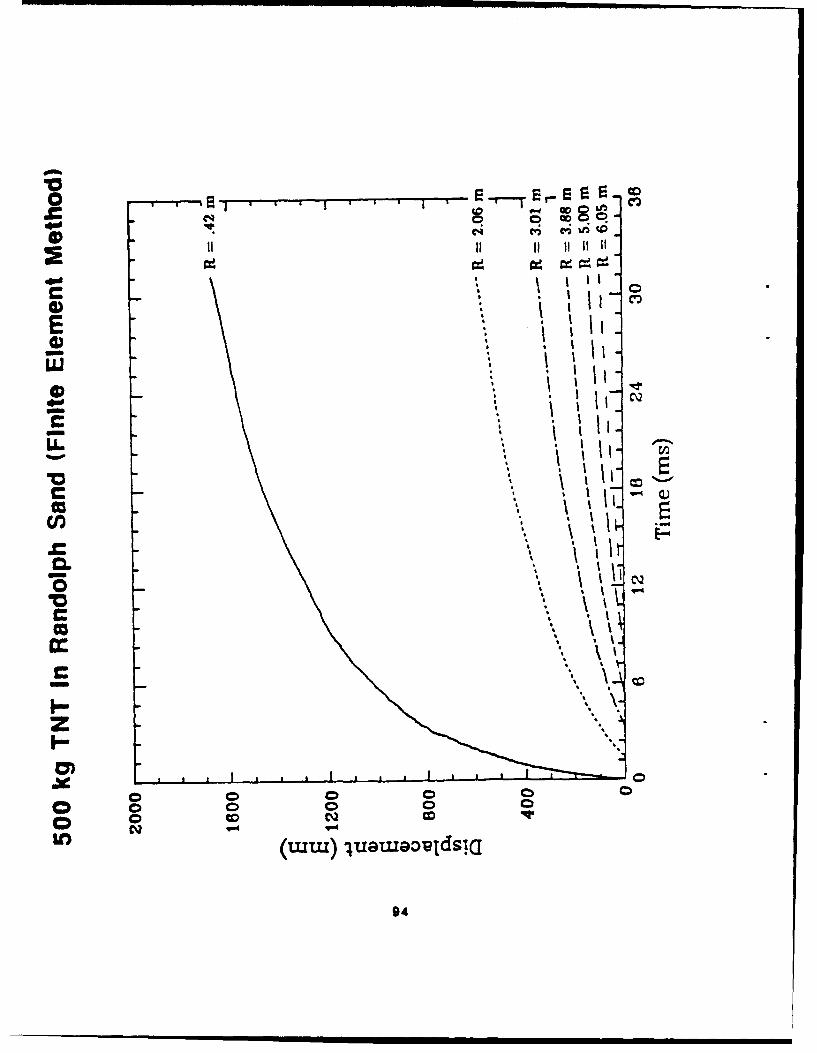
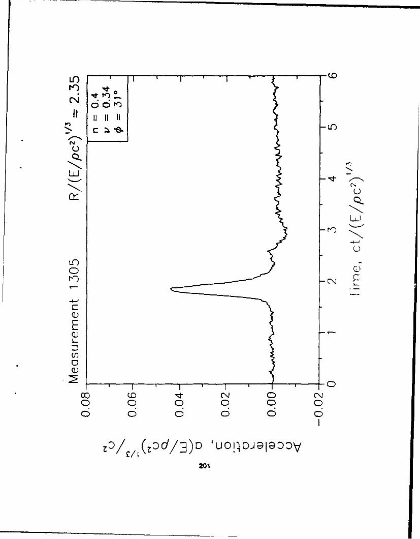
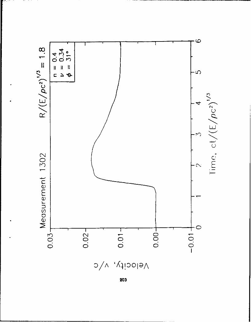
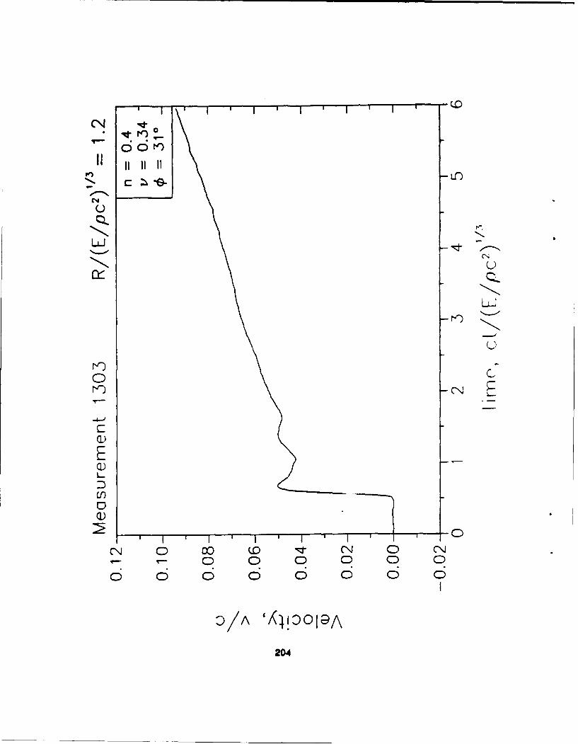
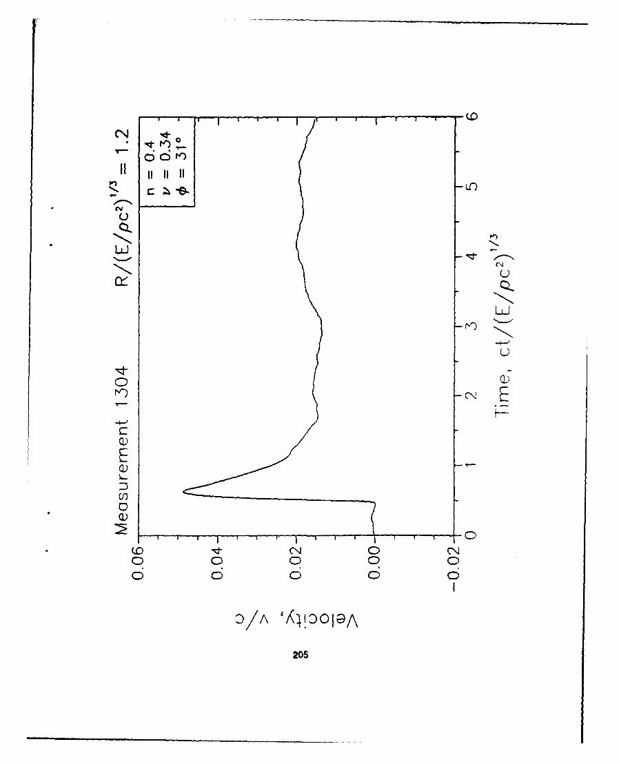
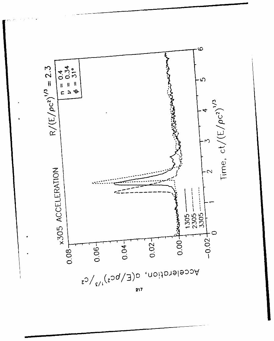
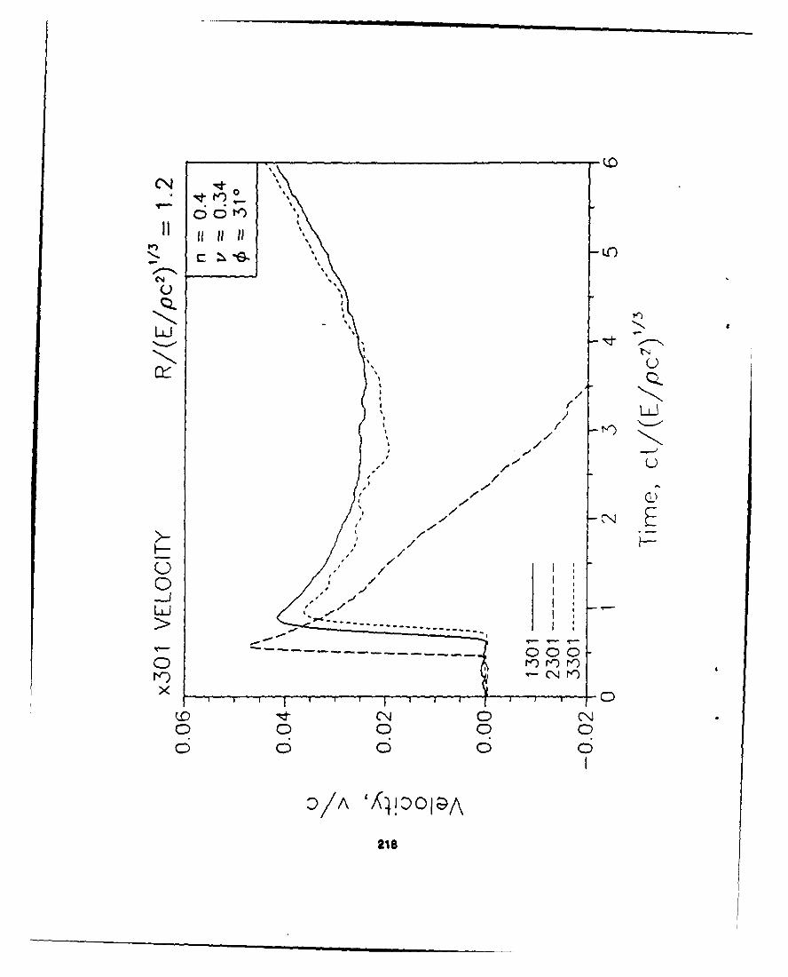
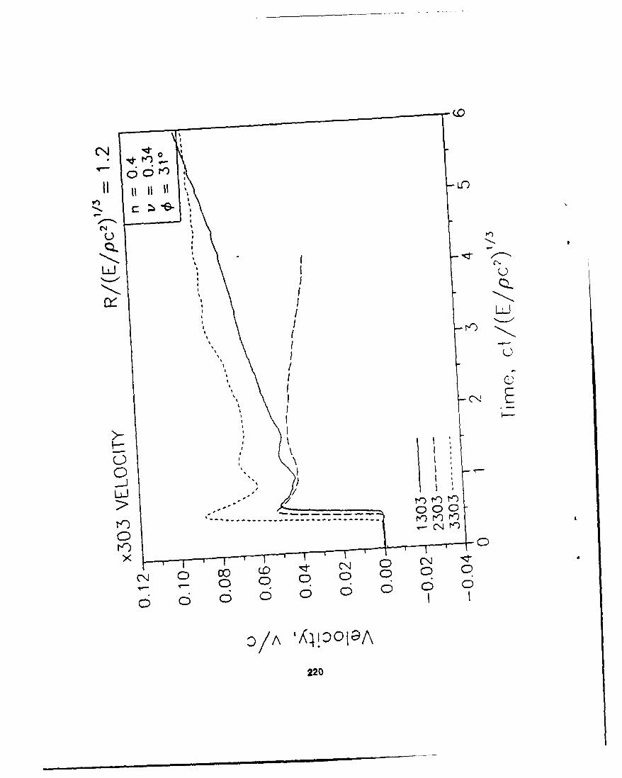
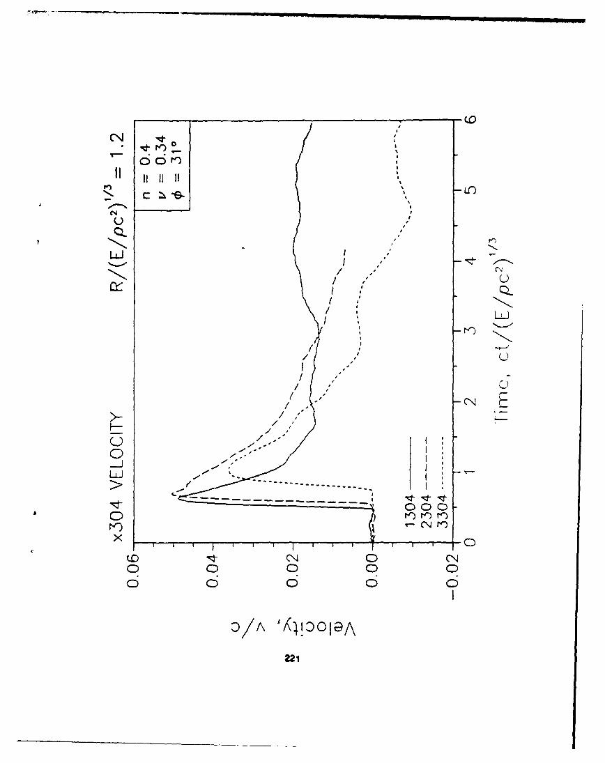
APPENDIX E
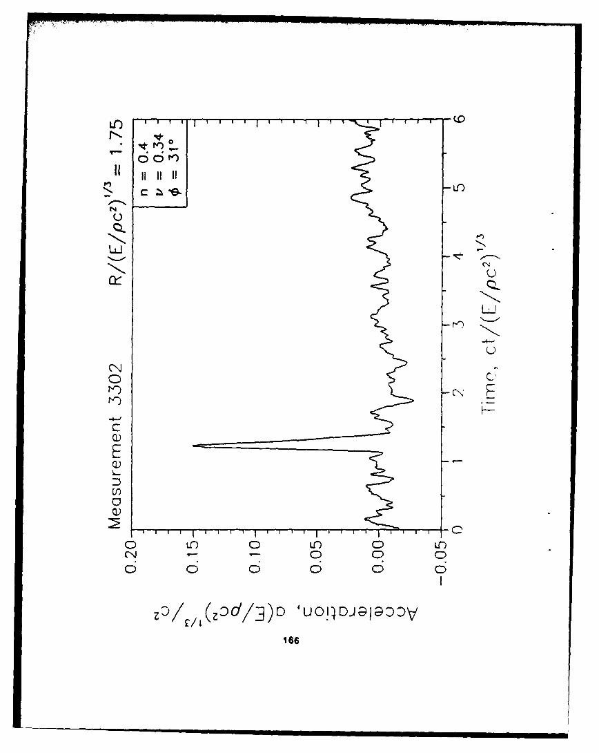
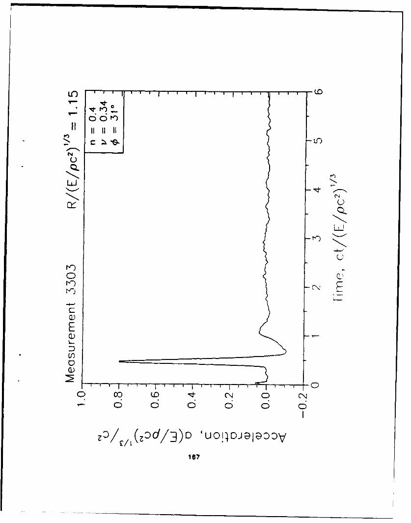
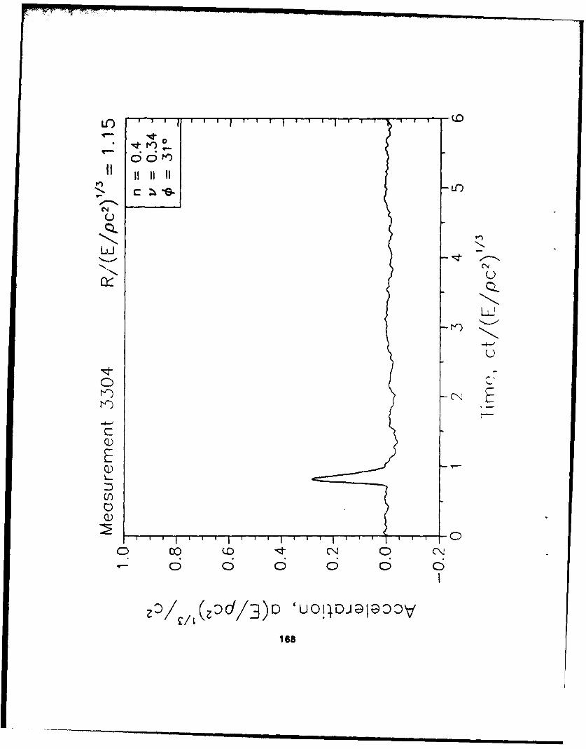
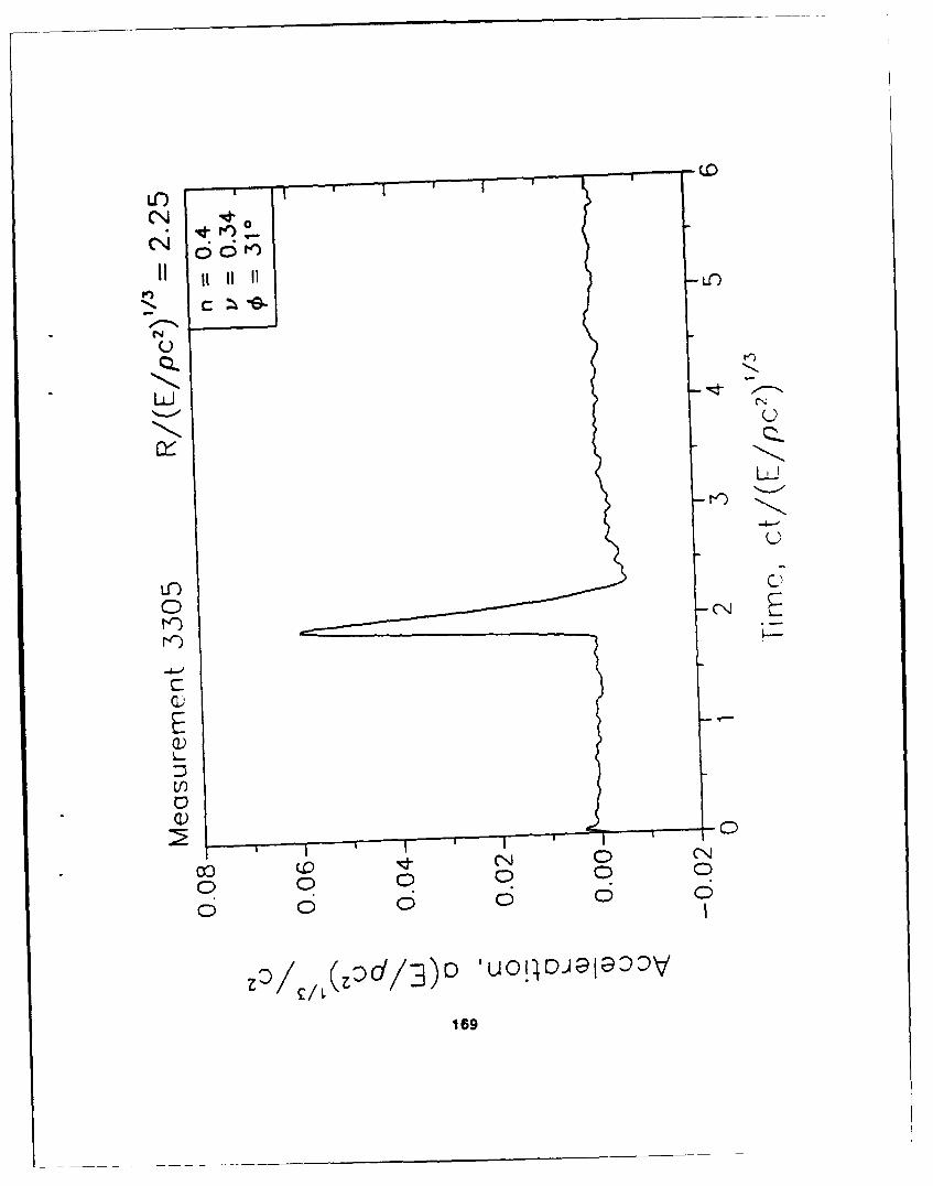
DATA PLOTS FROM DYNAMIC TESTS
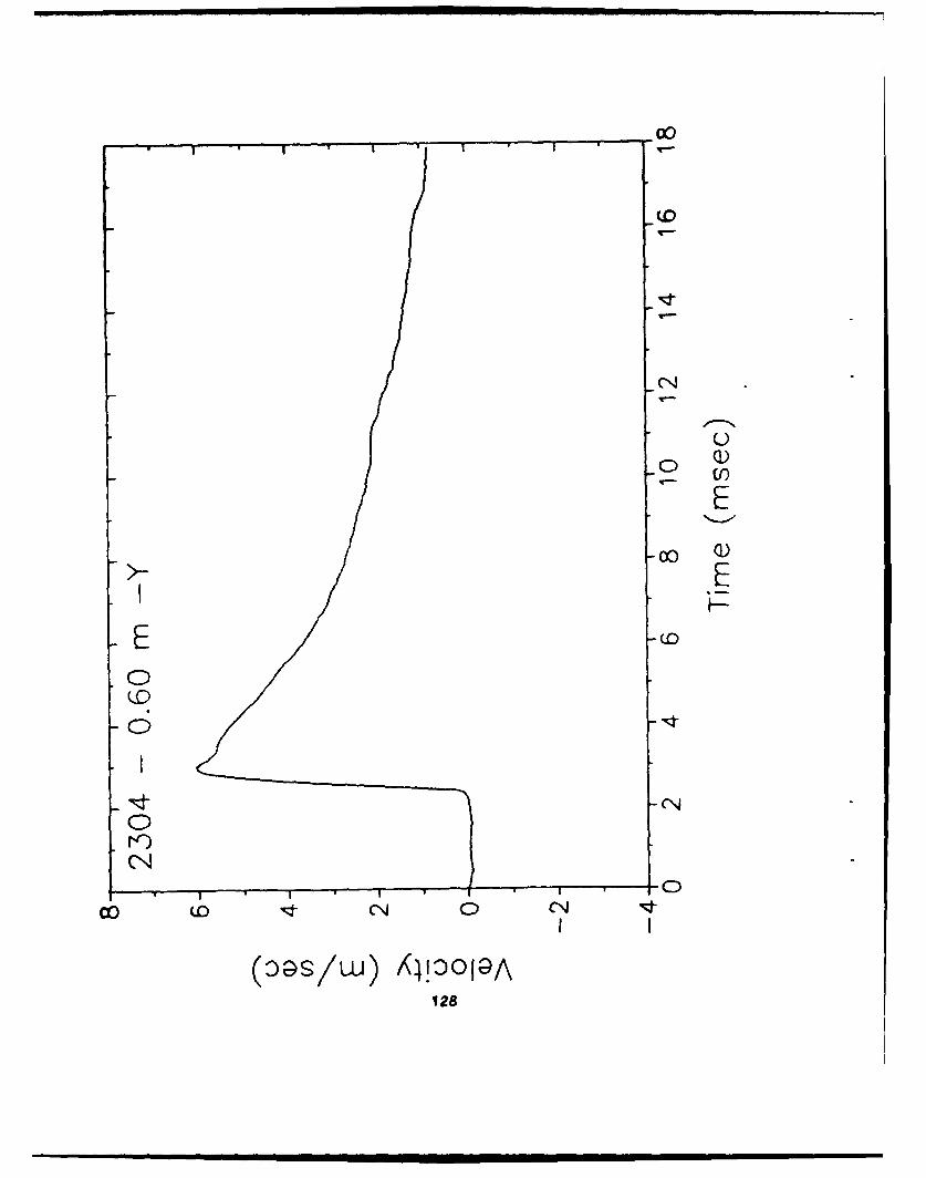
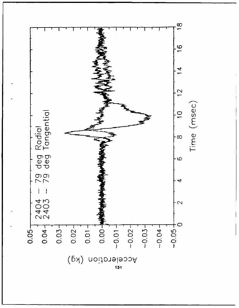
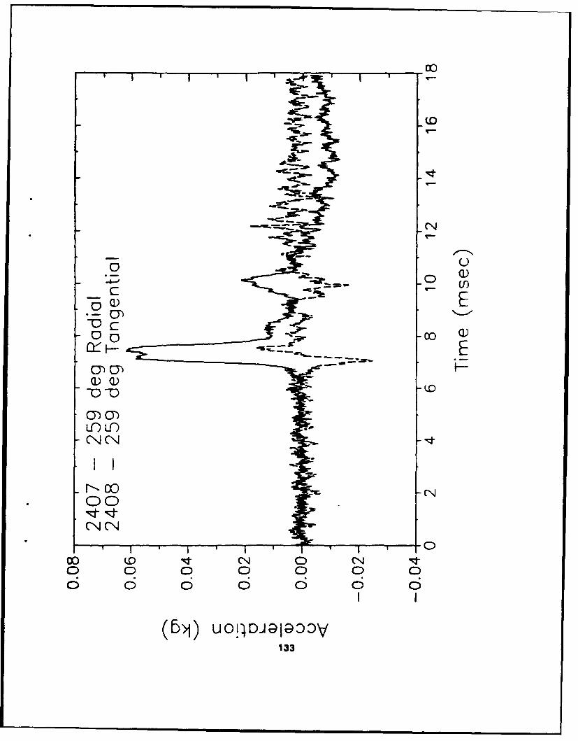
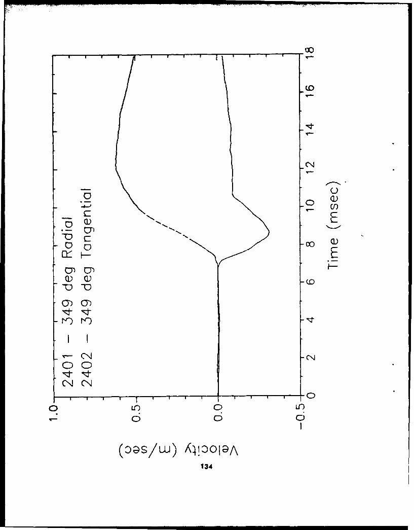
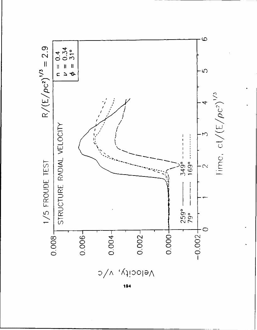
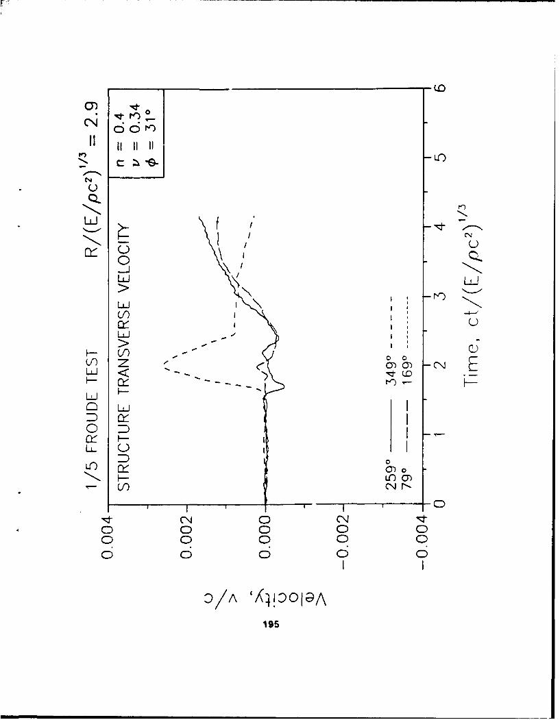
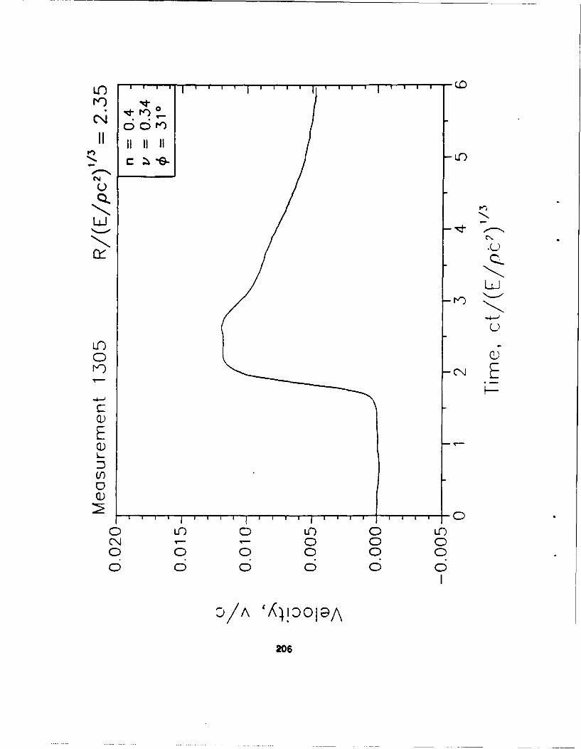
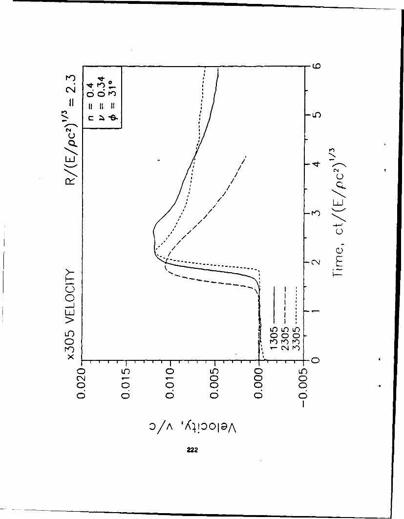
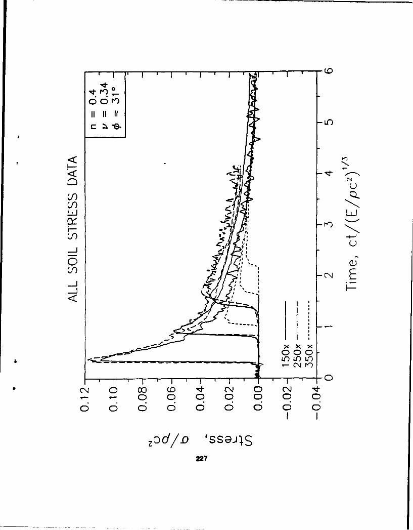
On the plots of accelerations and velocities on the structure, the radial values (with respect to thestructure) are plotted with solid lines, and the transverse values with dashed lines.
96
1/10 REPLICA SCALED TEST
"SAND"
97
E0
-0
98
S..... . I I IIE
LC)
%El0 1---
C\J
r 4 c
(5ý>) uoijDJ;Dja3)v99
LIf)
F T-1CN Lo
± FDJ-31aO
IOD

101)
L1)
Ex Qi)
+ EEfLO
00jLOl
0
0 0 0 0 0 0 0
102

(9
(1)U)
0_G)
o EcN4
E0
0)
00
00

n) 0Q-)U')
E
o E
10

LO~
t) uQ)cn'E
0)
E
+ H-0
00P
00
L6 0
106
-LC)
0)
E
+N EE
if)
Go
CC
o 00 0 0 0
107
4-j cn
-
07) CYlOu
000
000
a) a)
0 0
(50) a)j~aG0
0 10
-L()
4.
Q))
co) (9
/ t
00)
"It N
(0110
0 0
1 I I I I
(5>1) uoil~ac w)a110

rl_ co
00
It,
I I I I I
(bý) 014D~IG111
Ir
0Iizý- IC:I
IE-0I
_0 _I
0/ ))0()
0 C)
-40 0CI 3
o N....J
-o C( (2
-if)
CIL
0)I_0 _I
0V 0
_z I-t
D0 I
0 CD 0
I0-)SW 4I Ia
~tM113
0 c a)
0 C IryI
U /0-I) QI0 _
m -/D L
(D /-0I; I-
/f
I0
0 CN.
114~
Q) 0)
-Y) )G)
0 0
1;- zlC
C~115
CN)
61
LO
(I)
-E
0
00
(Ddjn) s~117
Lr)
04
1-4
(Danv) ssai~sl18
1/5 FROUDE SCALED TEST
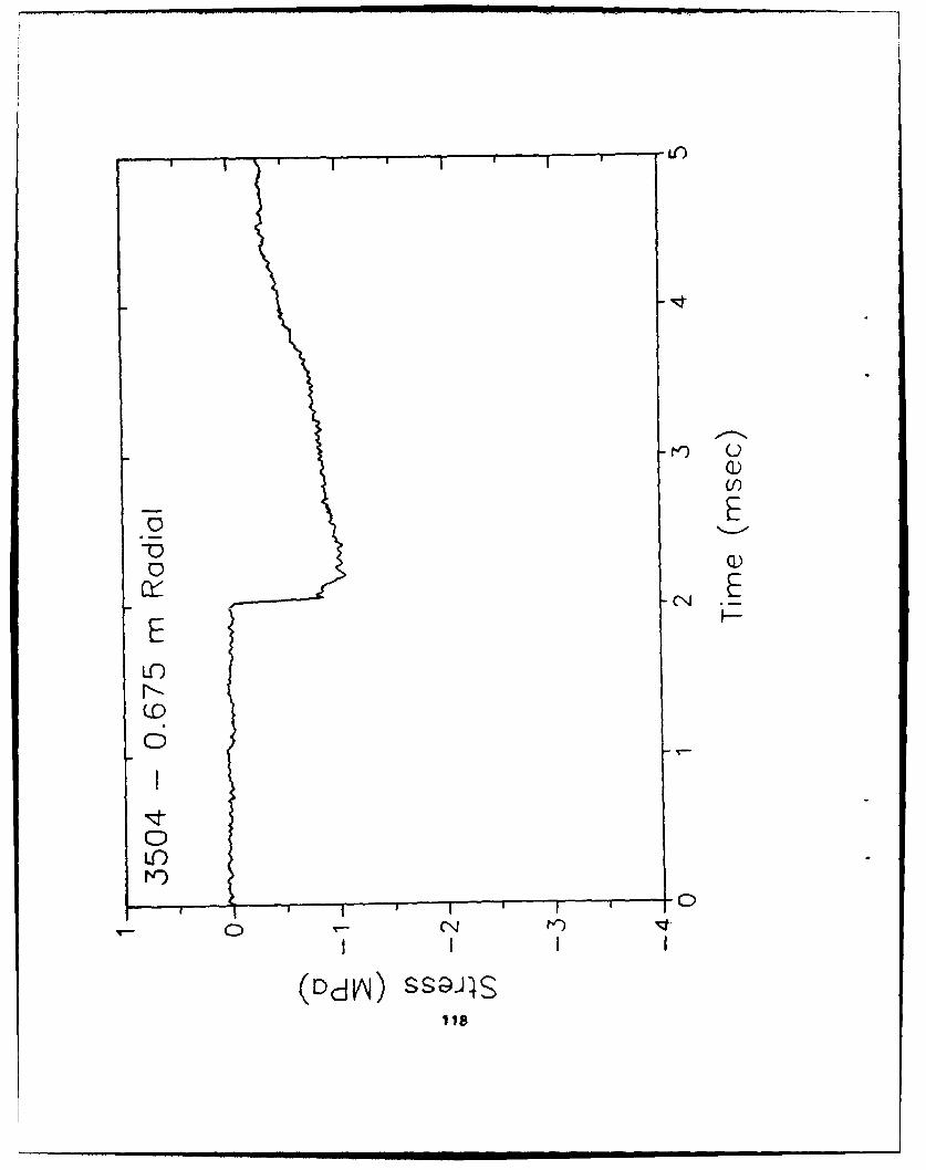
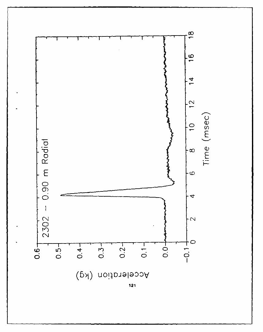
"COAL"
119
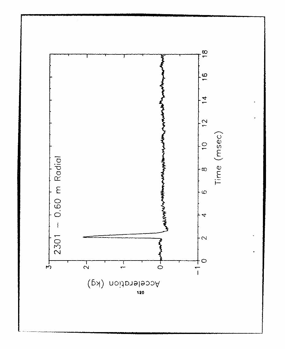
cto
(0
00q
12
co
CDI
CDE
(U0'tC4
U014DaiGOO
o121
00
0 q
UC)
Eo
1220
00
U)
E
I E
CC~J
CC
(bjý) UO!IDJaIG2DOV123

(0
-0 )
E
00 Q
0O u) ) 0) 10CJ0 0 0
124

_0 co_ U
EE
0+
o0U 19-C
(1Ds/w 401
02
(0
C)
E
o Eo
(0 (0/UJ 0012
00
C-)0 Q
coE
+E
M)a/w 431
12
00E)
EE.0c
E (
CC
001G
128

0o
(0
00
-FA o
0 L
0 0IC 0 0C
129

- (N
o (Q)-4-j' 0 fc T f)
OD 0
0)0C)'
00
NCN(
LOfld~:- V-) (N 0 - N K~) - i40 0 0 0 0 0 0 0 0 0 0
130
C:D
C:!
~00
0)0)
0 0
C1,1 rl 0-;IN ) - if)00 0 0 0 0 0 0 0 0 0
131

4C
__ (N
00 co Q)
E
000
N IN
CNtN) CNL
oo 0 0 0 0 0 0 0 0 0
132
DO
-600r-p.
Of F-
-0-0
000
0
0(
(5ý U1ODalDOLC)133
00
CD
U)
-0~
0 co
o00CNCNJ
0LC) 0
0 0 0
1 34
C-)
Er'C
_0 (0
In m
00
135
CN
co
-0 7D
(DLC N
NCCN
(cý)s/w) 400PA136

(0
(N
1n
0ELD Q)UU)
000
LO LC
ztc Nt
00
137
00
_00 CO
o 37
E L
U-)
(Ddjn) SSaJI138

0(
U-))
.- 4N-D C-Q00
* 0
(DdA) SS94139
co
0 c
0 IEE LO
V-)
10
o 3 6 6 6 05
(DdA) SS;JIS140

1/10 FROUDE SCALED TESTS
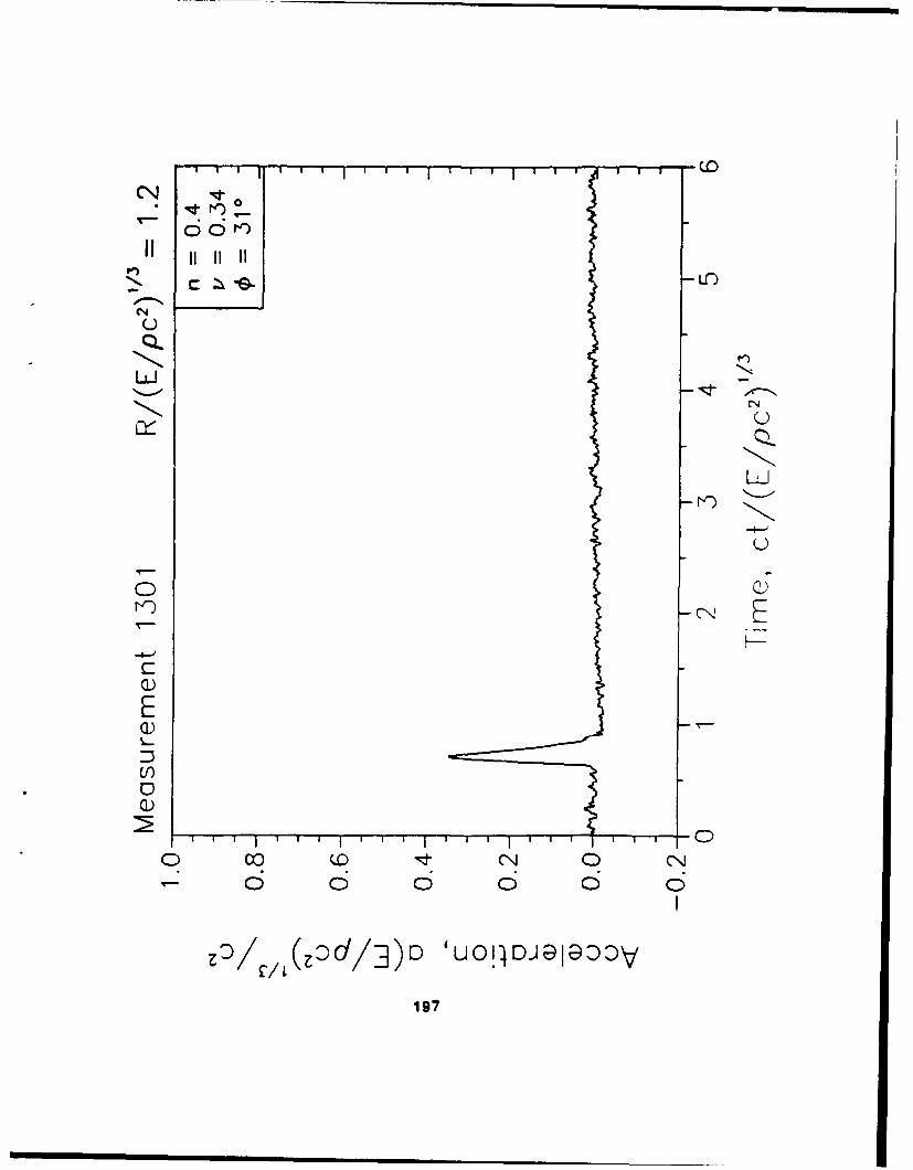
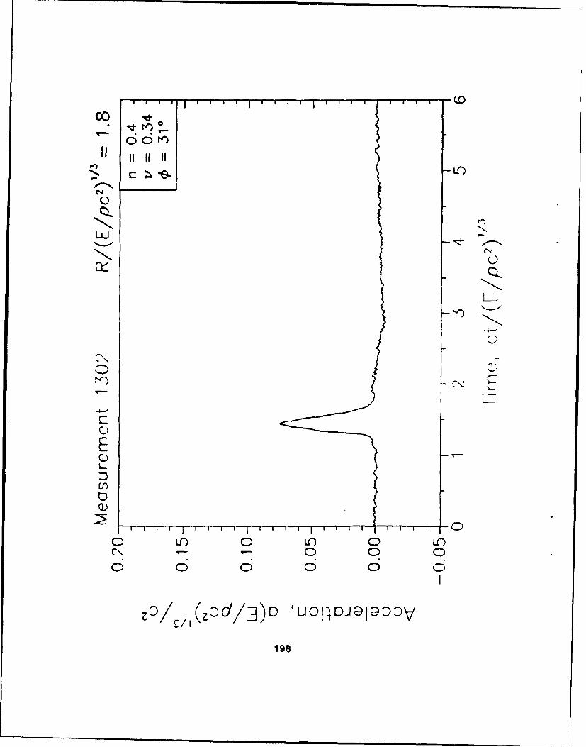
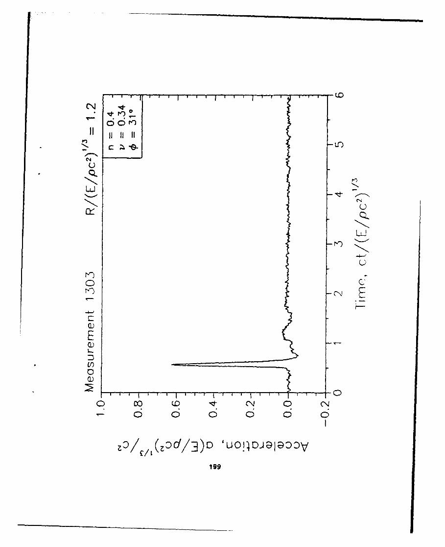
"LEAD/COAL"
141
0(CO
0N
0L
01
0 O 0 0 LC)
(bi) UOIIDJ;DI;DO'V142

(0 1
o E
LO)
C N CN0
-+otn1 0 T_
65 6 63 6 o 6
(si) uoiIDJalaDzKV143
144~
00
c-u
U)
E (0
0OjJ~a3N1)

(0)
EE
000
LO)
0 Ur) 0 L 0 LCJ0 0 0
(6ý) UO!4DJIa2aoV148

(0
cn
ECc Q
-o cc ý
o E01@147
(NJ
co
CDT
cic
(:D-'S/W) 0019o4
_ _ _ _ _ _ _ _ _ _ _ _ _ _ _ _ _ _ _ _ 00
0) in)
E
+ E
E C
-0
0
0 co D 0N
149
(0
U
co )E)
EE
00 C
L6
ISO
0 Q
C!)
00cLnL
Ln~
+ I I te l1 1E1 1 1 4
if)/w 401D
lid
- r c Q)C:-
Nd-~ --q
CN o C)- C-
C )) C)C.
000
'-152

C)
Q)-In
(E
CO-0
aL) a)-
0 C.) m
o) 0 00
153
0) 00
0) CY)
QO (D
(D LO
.55
0(
rl-- cc-
0)0
NCCD
I IDaaDD

1 (
It LO
CC
oc 144 zo (1)Z n lt
(Oas/w 400E
IIse

0 CDN
157

I I I I OD
/(00CY E0) CY/Q) 0)
/ 0
6 C3C 3o
00 s u)AL0G15
jcrj
a 0) 1// (
0 C) -/
_0 _0
-o
(:Ds/w E3iG0 c~ oc159
CN
10
(DcjA)ss~U)
ISO
C)0 Q)
E
o E,
CN CN0LC)
r T-o
161

oo
E (
Cl\jLO
C*4 0t (0 (0 06 o; 6 o6 6
162
APPENDIX F
SCALED DATA PLOTS FROMDYNAMIC TESTS
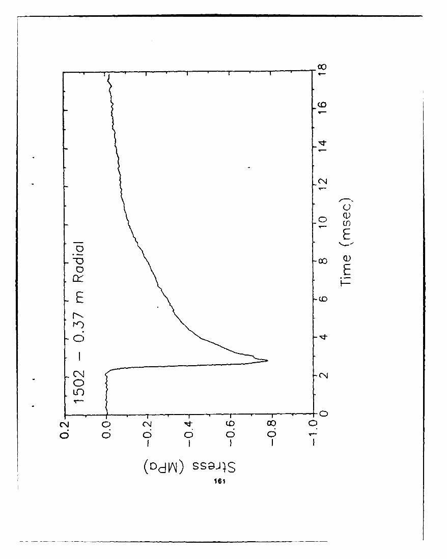
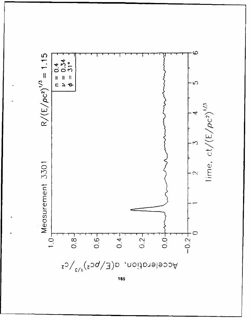
For the structure velocity plots, the sign of the data were changed where necessary so that allvelocity vectors point in the same direction. Positive radial velocities point away from the charge;positive transverse velocities point upward, normal to the radial velocities.
a- accelerationv- velocityE- energy released by burstp - density of soilc- wave propagation velocity of soilt - timeR- range from bursti - porosityv - Poisson's ratio
o- angle of internal frictiona- stress
163
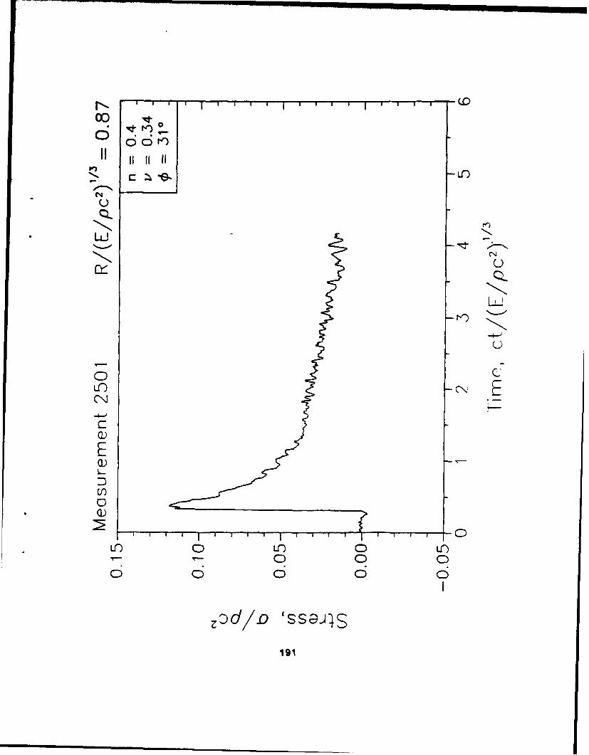
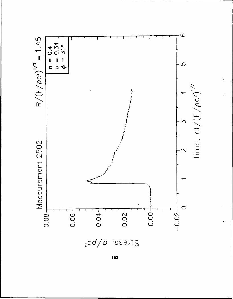
1/10 REPLICA SCALED TEST
"SAND"
164
C:) 0~,--
LO
CLLCNE
VQ)
CE
EQ)
CC
o 0z C) 0 (
-z/ /(Z~d/3)ID 'uO0!4 D-J a -4 ) V
LO)
CN
LU -
cU
LOi
T0 0 C0:
00
0 0 00
U, /~~/3D'O4DJ9aDD
NC
NON
CD)
00
0)0
E z/(:d3 U0 4IJ- ,ýDO0)6
0*
OQLO
C))
0
0)01
0 0/ C)' 0(NalOD
NtIN to ,
IIý c; iii;t
IQ)
Lii
Lro CN
0 NE
0) 0
169
Ný
U~ C-0 0
10

*00
Q)~
Ed I C
U)
o 0)
00
0D/A 'A/4!01IG-)A
1 71
ii II IIL
U
LUJ
Q))
Q)Q
ro)
0 0N
0 0 0
Q)/

0(
e') L.Cn
CJN
Q)QEU
00
O/A 44!0 0 NE
M17
CNI
LU)
Q)L-i
0
0 uO 0 u 0 u")c,, T-- T,- 0 0 0o 0) C o o
O/A '44!,0 0 1,A
174
V) I I I E
OO'ci
CN
QLQLLJU
CN 0
CN
0)
EQ)
Q)
00 U N 0 CNJ0 0 C0 0 0 00 0 0 0 0
zDd/D0 'SSG~J43
175
00
C) 0 r-)
LU
CL
LO)
Q)"E2C
Lt) n 0 CNo 0 0 0 0 0 0 00 0 0 6 0 0
:d/(D 'SS,9-J4S
176
Q.0
CN
C)I)
a))
L..J
C!)0
0~ cc 0 0 0 00- 0 0 0 0 0 0o 0 0 6 6 0 0
~zd/flD 'SSGJI5
0) 0c; C;
ocr 7n
IIL i
< <I
LiL
n~ r,,
C 00
L4J C0 0-
(/) 'A!00J DL17
C) 1!re%,ýI
% %
I'II II II II ', ' •
\C 1
S •- Iw• I" "
! I:•) I ",9
/' / 1 . I.. ..
-- > *.__
Lii
LLJ Z "--
_I II
D0-
CN 00 0 0 0 00 0 0 0 00 0 0I I
a)/A '44P 0a1A1719
1/5 FROUIDE SCALED TEST
"~COAL"
180
I',
Q)f
E
QU
C/-)
CCL
Q.u~j -C:
0 0 LO0U
00

L1) I ' I I I ' I I I I I I I I I I I 'D
V2 *
CN
E
Q)
0
~0 00 D • o 0 "
183
CNI

LI C
zzy (zcd/3ID ' 0 1 c)',-ý1;9: (9
184
LO CD
0~ 0
ULr)
CCM)
0Q)
C l
C)
CC)
0O 0 0N0 0 0 0 00
185
INI c i i f
1 LJ CN
MQ)
Q)
0)
Q)
00C0)0
o 0 0
186
Cf ) 0 I I
QOL)
c~c,-
NC
oU0 0 0 0
w/ 40 9K1137
C14
L)
ML)oy C)
Q)
EQ)
N 0 0 0 0 N0 0 0 0 0 0 0 0
2/A'fOA
188
* 1o
"- dLn
6
t•)
CL,
c--U
0
KCL
CDC:
Q)
E
(0 0 0 0
0C0 0 0 0
3/A '44 0aol1A
189

CNJ
0 0
LC)
CN
E
0)0
0)0
190
r io I I I I I * I I I T -
w -.
CN C
U-) (NEl
(N
0)
C0 0N 0 0N
0 0 0 0 0 0
192

'i 6
CL
NN
rr)
w -
0))
CCif) 19t nE
o 0 00N
0 0 0 0 0 0 0
0: f S ,
C193
c'Jj
Ui
'N
11 - .1--
0 1~ 0
wn C) o
s-O C)C
H- - 0
(p -
LU 0
0 0
LC) '4 0) 1,a
194C
C-(.
Li11 LC)
>
CI Q
.- I
IN 0
(/ 0 000
2:/ '44P)OPANIii ~-~ =9-
1/10 FROUDE SCALED TEST
"LEAD/COAL"
196
c -O
04N
Q)
o qLnN
-1 T I-
0 c IEz0
0o Z)(3 D ' 4CJ9I@DD
U)/
197
-LO
CNN
L0 0
19(9
cr -A.
C\4
119

6 6i
cU-
CL\
LLJi
CD)
CC
E
Q)
0 : (0zd 3 1 u01 c)NJ9 0; c)N)
200
KC) '
COI'ý
' i 6I I ILC
nULc0:ý
CN
LO)o
Q)
0)0
020

QQV)
Q))
0
Q)
20
00~
oonv~
UU
CL)
CN C0
Q0E
Q)
00
203
NC
II II II II
0 -
0, , 0 0 0 0 0 0
I-
:D/A '400P~lA
w 204
CN
LLC)
LU -J
()
wN
00
0)0
0)0
o 0'
II H H
U
CL)LO
0
c-O
(I..)
0O
c) c
E
0
' ' ' I ° ' ' ' ° ' I ' ' I I CO ) C LC) 0 U-)
0N 0 0 00 0 0 0 0 06 c o c6 o 65
O/A '401926 A
206
Oo o
NC
i-Li
0LC)
Cr L r
0 0
0 0 0
~ZdC/D 'SSGJ4S
207
LC)
CNU
CLi
CNN
CC
0))
E
LO)
CC
0 0 0000 0 0 0
zod/o 'ss@.)4
208

NC
V)V
0w
0
020
0 (.0 J e
M)e
C)LC
Li/
Lii <
r(9
0L N. M0 Z
V)QVN E
00 clli 0 -0
2100

0
. In
CL j
I I
L)CI i
Li LtJ
Li
U I
* p')
>U) I - -
Li i'
LLi0 I
L L i
LUN z -
0- 0
0 0
2211
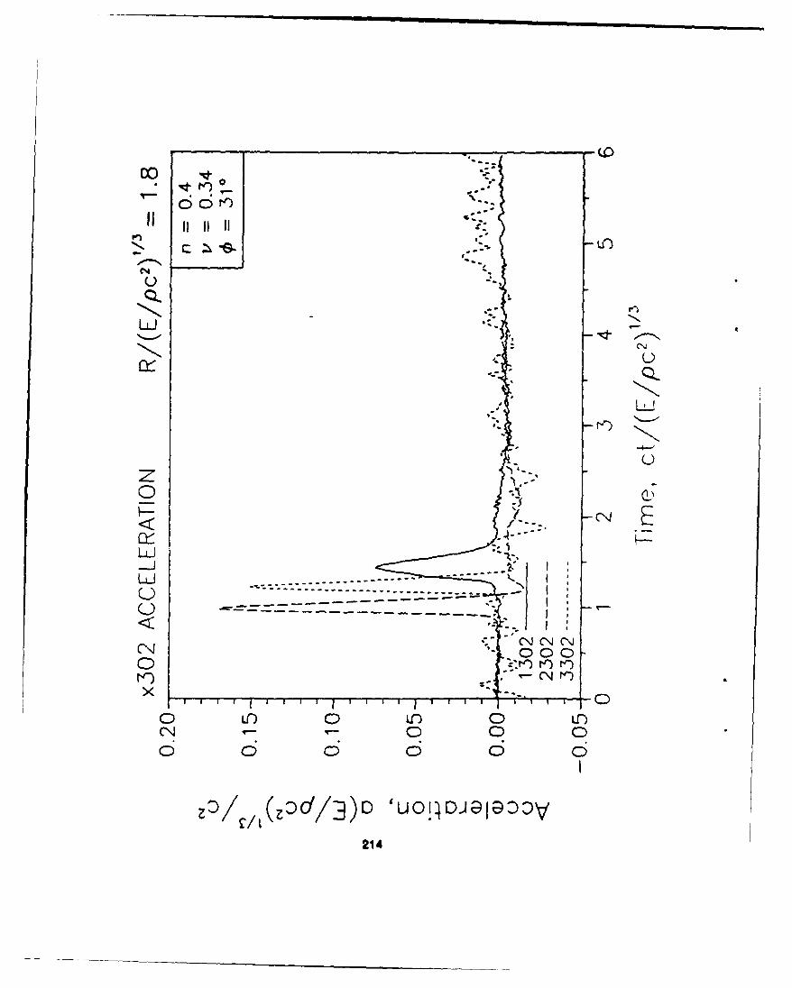
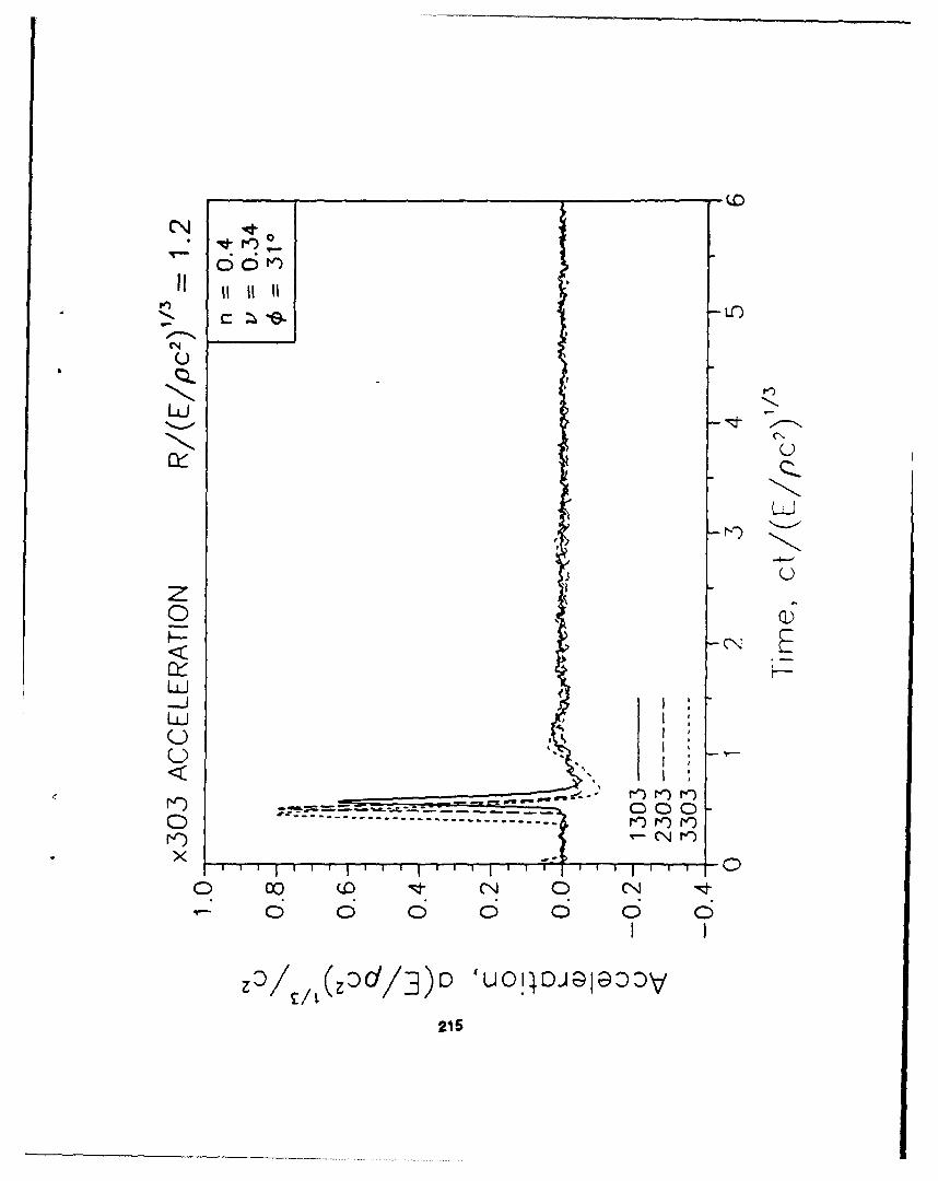
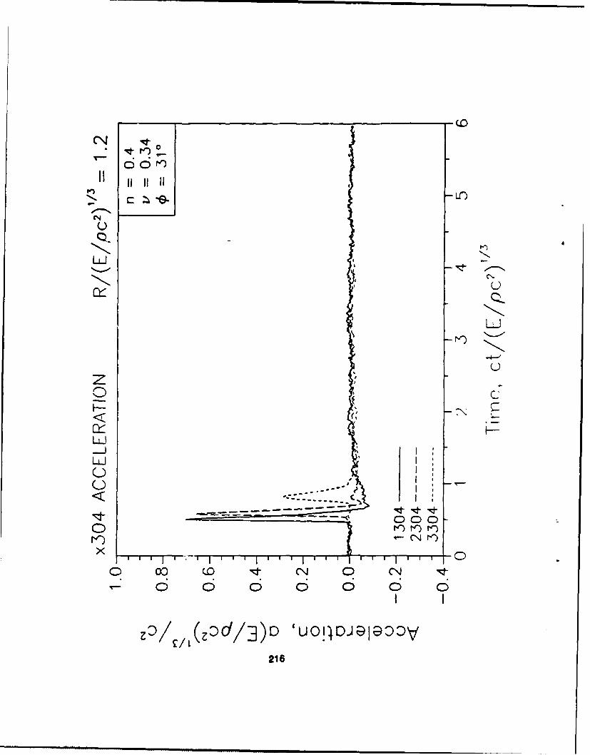
APPENDIX G
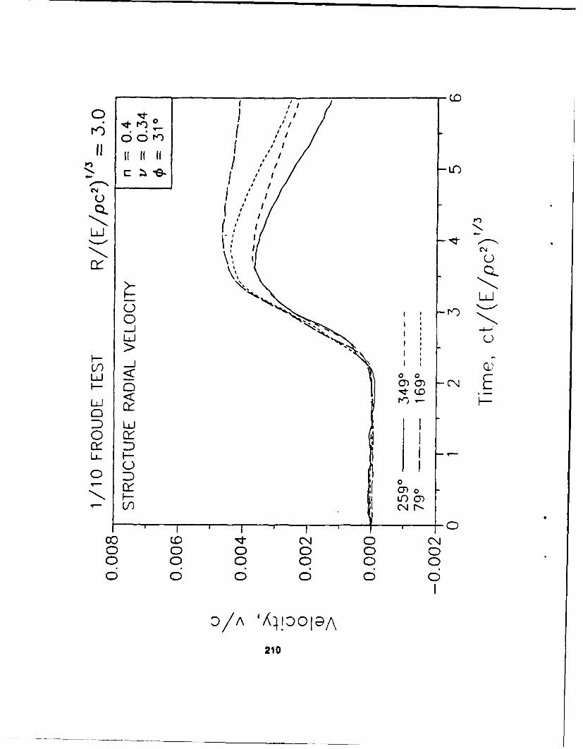
COMPOSITE NONDIMENSIONAL DATAPLOTS FROM DYNAMIC TESTS
212

CN
!Z c I ;i LO)
NC
0
K -. CNn
o 00
o 0 )
Li/
o 213
IINLC)
L)
0 0 C)
0 -0 0 C 0 0)
Zo (D(/3 1 U0 4 J -)I G(NEO
214:
00
0 Q
Li
(C 1%
o -o
o 00~ 0 NI-
0 0 0 0
1 c/ (zcd/3)D) 'uOI4 c)J I;D 0V
215
O~r')
LC)
UU4
N. ixU T
I FT-~
Sý/ L
216.
CL CN
L)
-JL
u-i
0 0
X ........ 0
It0
0 0 C
&//L( 0zd/3)D
II tl tl It'
L o
S j
LOi
• /p I / ,
/ i ,/
*-/ . i CN -
0 0 ,,0 /
------------ -- 000o M ,o 'o
(0 •I- o•0 C'0 0 0 0 06 o 6 o 6
D/A '44!ZOl0A
218

-LO
II 11 11 11"- .
V.- "- ..
N *W %
I,'
I,, u
% -- -- -
ro 1-).r
0 0
o -
-I
O/A 'Xl!:D 0 1 A
219
CL4
_I IU I
LU0
o" , I
--t -"-- -00
I o 0
0 0
,I /
0 I C?-
... A "', ) )I
S2200
c'q 00 .D • o,10 '6, ,-. 0 0 0 0C 0 0 O
220
CL
L0J
_t
>f
LiL
-- ' 7 " -- "- -1 - - - - -, -
- tS0 0 0 -
II
E21r
At 0 C)C 0 0
0 0 0)
:// - -01
pr')
Q0"
U LC)
Lii
O Coc-
x 0)
o 0 O 'CN V- r- 0
uJ 0 00
o0f 0 0
222

00 0
U-
Lii
00LLi
x -1 C)
223

0(
C)e
uJ
C)
ry QL
O-f
000
V)I f
0 000
0 00 0 0 0
ZOd/D 'S-Djls
224

0
C,'ý
U
) :L)
1 41
U-) cC-)
0~ 0 0
(/)d/ ss,9j
w -225

it It~
4 4 O
4 4 4 4
4 4.
rL 44
*T I I 1 -1 1 4
.4 00 Q0 I 4 0 4 ý d
1/ 4 rD
4 226
UI II II
11 111 1Ici LO
GOa
.- J ...
Of/ I
00 -o
0 0 0 0 0 0 0
I I
O d/D 'SSJIS227