navair 01-1a-8 structural hardware
TRANSCRIPT
1 OCTOBER 1999
NAVAIR 01--1A--8
Change 1 -- 1 July 2003
TECHNICAL MANUAL
ENGINEERING MANUAL SERIES
AIRCRAFT AND MISSILE REPAIR
STRUCTURAL HARDWARE
DISTRIBUTION STATEMENT C. Distribution authorized to U.S. Government agencies and theircontractors to protect publications required for official use or for administrative or operationalpurposes only, effective 1 October 1999. Other requests for this document shall be referred to:Commanding Officer, Naval Air Technical Data Engineering Service Command, NAS North Island,PO Box 357031, Building 90 Distribution, San Diego, CA 92135--7031.
DESTRUCTION NOTICE -- For unclassified, limited documents, destroy by any method that willprevent disclosure of contents or reconstruction of the document.
COGNIZANT FIELD ACTIVITY: NAVAL AVIATION DEPOT (Code 3.3.1)Naval Air StationJacksonville, FL 32212-0016
PUBLISHED BY DIRECTION OF THE COMMANDER, NAVAL AIR SYSTEMS COMMAND
NATEC ELECTRONIC MANUAL
0801LP1027189
NAVAIR 01--1A--8
LIST OF EFFECTIVE PAGES
Insert latest changed pages; dispose of superseded pages in accordance with applicable regulations.
A Change 1
NOTE: On a changed page, the portion of the text and illustrations affected by the latest change is indicated by avertical line, or other change symbol, in the outer margin of the page. Changes to wiring diagrams are indicated byshaded areas.
Dates of issue for original and changed pages are:
Original 0 1 Oct 1999 Change 1 1 July 2003. . . . . . . . . . . . . . . . . . . . . . . . . . . . . . . . . . . . . . . . . . . . . . . . . . . . . . . .(with IRACS 1 and 3 incorporated, IRAC 2 cancelled)
Total number of pages in this manual is 430 consisting of the following:
Change Change ChangePage No. No. Page No. No. Page No. No.
Title 1. . . . . . . . . . . . . . . . . . .
A 1. . . . . . . . . . . . . . . . . . . . . .
i — iii 0. . . . . . . . . . . . . . . . . .
iv 1. . . . . . . . . . . . . . . . . . . . . .
v 0. . . . . . . . . . . . . . . . . . . . . .
vi 1. . . . . . . . . . . . . . . . . . . . . .
vii — ix 0. . . . . . . . . . . . . . . . .
x 1. . . . . . . . . . . . . . . . . . . . . .
xi 0. . . . . . . . . . . . . . . . . . . . . .
xii 1. . . . . . . . . . . . . . . . . . . . .
xiii — xv 0. . . . . . . . . . . . . . . .
xvi Blank 0. . . . . . . . . . . . . . .
1--1 — 1--3 0. . . . . . . . . . . . .
1--4 Blank 0. . . . . . . . . . . . . .
2--1 — 2--39 0. . . . . . . . . . . .
2--40 Blank 0. . . . . . . . . . . . .
3--1 — 3--35 0. . . . . . . . . . . .
3--36 1. . . . . . . . . . . . . . . . . . .
3--37 — 3--100 0. . . . . . . . . .
4--1 — 4--2 0. . . . . . . . . . . . .
4--3 0. . . . . . . . . . . . . . . . . . . .
4--4 Blank 0. . . . . . . . . . . . . .
4--5 0. . . . . . . . . . . . . . . . . . . .
4--6 Blank 0. . . . . . . . . . . . . .
4--7 0. . . . . . . . . . . . . . . . . . . .
4--8 Blank 0. . . . . . . . . . . . . .
4--9 0. . . . . . . . . . . . . . . . . . . .
4--10 Blank 0. . . . . . . . . . . . .
4--11 — 4--37 0. . . . . . . . . . .
4--38 Blank 0. . . . . . . . . . . . .
5--1 — 5--37 0. . . . . . . . . . . .
5--38 Blank 0. . . . . . . . . . . . .
6--1 — 6--8 0. . . . . . . . . . . . .
7--1 — 7--3 0. . . . . . . . . . . . .
7--4 1. . . . . . . . . . . . . . . . . . . .
7--5 — 7--38 0. . . . . . . . . . . .
8--1 — 8--18 0. . . . . . . . . . . .
9--1 — 9--20 0. . . . . . . . . . . .
10--1 — 10--2 1. . . . . . . . . . .
10--3 — 10--6 0. . . . . . . . . . .
10--7 — 10--17 1. . . . . . . . . .
10--18 Blank 1. . . . . . . . . . . .
11--1 — 11--18 0. . . . . . . . . .
12--1 — 12--16 0. . . . . . . . . .
12--17 1. . . . . . . . . . . . . . . . .
12--18 Blank 1. . . . . . . . . . . .
13--1 — 13--21 0. . . . . . . . . .
13--22 Blank 0. . . . . . . . . . . .
14--1 — 14--10 0. . . . . . . . . .
15--1 — 15--13 0. . . . . . . . . .
15--14 Blank 0. . . . . . . . . . . .
16--1 — 16--2 0. . . . . . . . . . .
Index 1 — Index 6 0. . . . . . .

NAVAIR 01-1A-8
i
TABLE OF CONTENTS
Section Page Section Page
LIST OF ILLUSTRATIONS v. . . . . . . . . . . . . . . . . LIST OF TABLES vii. . . . . . . . . . . . . . . . . . . . . . . . . LIST OF VALID TECHNICAL PUBLICATION
DEFICIENCY REPORTS (TPDR)INCORPORATED xii. . . . . . . . . . . . . . . . . . . . . . .
WARNING APPLICABLE TO HAZARDOUSMATERIALS xiii. . . . . . . . . . . . . . . . . . . . . . . . . . . .
I INTRODUCTION 1-1. . . . . . . . . . . . . . . . . . . . .
1-1. Purpose 1-1. . . . . . . . . . . . . . . . . . . . . . 1-3. Scope 1-1. . . . . . . . . . . . . . . . . . . . . . . . 1-8. Requisitioning and Automatic
Distribution of NavairTechnical Publications 1-2. . . . . . . .
1-10. Warnings, Cautions and Notes 1-2. . . 1-13. Wording 1-2. . . . . . . . . . . . . . . . . . . . . . 1-15. Changes to Manual 1-2. . . . . . . . . . . .
II GENERAL HARDWARE PROCESSES 2.1. .
2-1. General 2-1. . . . . . . . . . . . . . . . . . . . . . . 2–3. Locating Trim Lines 2-1.. . . . . . . . . . . . 2–4. Skin Scribe Method for Locating
Trim Lines 2-1.. . . . . . . . . . . . . . . . . . 2–5. Tape Method for Locating
Trim Lines 2-1.. . . . . . . . . . . . . . . . . . . . 2–6. Locating Blind Holes 2-1.. . . . . . . . . . . . 2–7. Hole Finder Method for Locating
Blind Holes 2-1.. . . . . . . . . . . . . . . . . . . . 2–8. Hole Transfer Punch Method for
Locating Blind Holes 2-5.. . . . . . . . . . . . 2–9. Measuring and Scaling Method
for Locating Blind Holes 2-5.. . . . . . . . . 2–10. Hydrocal Drill Blanket Method for
Locating Bland Holes 2-8.. . . . . . . . . . . 2–11. Hydrocal Procedure for a Panel/
Door 2-8.. . . . . . . . . . . . . . . . . . . . . . . . . 2–12. Hydrocal Procedure for a
Component Replacement 2-13.. . . . . . . 2-13. Drilling 2-14. . . . . . . . . . . . . . . . . . . . . . . . 2-14. Drilling Equipment for Metallic
Structures 2-14. . . . . . . . . . . . . . . . . . 2-15. Drilling Metallic Structures 2-14. . . . . . . 2-16. Drilling Graphite/Epoxy
Laminates 2-14. . . . . . . . . . . . . . . . . . 2-17. Tool Maintenance 2-16. . . . . . . . . . . . . . 2-18. Hand Drilling Graphite/Epoxy
Laminates 2-16. . . . . . . . . . . . . . . . . . 2-19. Drilling Boron/Epoxy Laminates 2-16. . 2-20. Countersinking and Dimpling 2-18. . . . 2-21. Countersinking Metallic
Structures 2-18. . . . . . . . . . . . . . . . . . 2-22. Machine Countersinking 2-18. . . . . . . . 2-23. Dimpling Metallic Structures 2-18. . . . . 2-24. Subcountersinking Metallic
Structures 2-20. . . . . . . . . . . . . . . . . .
2-25. Countersinking CompositeStructures 2-20. . . . . . . . . . . . . . . . . .
2-26. Tapping 2-20. . . . . . . . . . . . . . . . . . . . . . . 2-27. Thread-Cutting Taps 2-20. . . . . . . . . . . . 2-28. Styles of Taps 2-20. . . . . . . . . . . . . . . . . 2-29. Selection of Thread-Cutting Taps 2-20. 2-30. Torquing 2-20. . . . . . . . . . . . . . . . . . . . . . 2-31. Torque 2-20. . . . . . . . . . . . . . . . . . . . . . . . 2-32. Forces 2-23. . . . . . . . . . . . . . . . . . . . . . . 2-33. Variables Affecting Torque 2-23. . . . . . . 2-34. Torquing Nuts and Bolts 2-23. . . . . . . . 2-35. Torque Wrenches 2-23. . . . . . . . . . . . . . 2-36. Use of Torque Wrenches 2-26. . . . . . . . 2-37. Precautions 2-26. . . . . . . . . . . . . . . . . . . 2-38. Safety Wiring and Cotter Pins 2-26. . . 2-39. Safety Wiring 2-26. . . . . . . . . . . . . . . . . . 2-40. Shear Wiring 2-26.. . . . . . . . . . . . . . . . . . 2-41. Safety Wiring Materials 2-26. . . . . . . . . 2-42. Safety Wiring Procedure 2-26. . . . . . . . 2-43. Use of Wire Twisters 2-34. . . . . . . . . . . 2-44. Securing Oil Caps, Drain Cocks,
and Valves 2-34. . . . . . . . . . . . . . . . . . 2-45. Securing Turnbuckles 2-34. . . . . . . . . . 2-46. Safety Wiring Guidelines and
Precautions 2-36. . . . . . . . . . . . . . . . . 2-47. Cotter Pins 2-37. . . . . . . . . . . . . . . . . . . . 2-48. Bucking and Shaving Rivets 2-37. . . . . 2-49. Bucking 2-37. . . . . . . . . . . . . . . . . . . . . . . 2-50. Bucking Bars 2-37. . . . . . . . . . . . . . . . . . 2-51. Bucking Rivets 2-39. . . . . . . . . . . . . . . . 2-52. Shaving Rivet Heads 2-39. . . . . . . . . . .
III RIVETS 3-1. . . . . . . . . . . . . . . . . . . . . . . . . . . . .
3-1. Rivets 3-1. . . . . . . . . . . . . . . . . . . . . . . . 3-3. Rivet Part Numbers 3-1. . . . . . . . . . . . 3-4. Rivet Identification 3-1. . . . . . . . . . . . . 3-5. Rivet Materials 3-1. . . . . . . . . . . . . . . . 3-6. Rivet Corrosion Resistance 3-1. . . . . . 3-7. Rivet Pattern Layout 3-1. . . . . . . . . . . . 3-8. Drilling Rivet Holes 3-2. . . . . . . . . . . . . 3-9. Hole Preparation for Rivets 3-2. . . . . . 3-10. Rivet Failure 3-2. . . . . . . . . . . . . . . . . . 3-11. Solid Rivets 3-4. . . . . . . . . . . . . . . . . . . 3-13. Solid Rivet Strength 3-4. . . . . . . . . . . . 3-14. Determination of Solid Rivet
Length 3-4. . . . . . . . . . . . . . . . . . . . . 3-15. Substitution and Interchangeability
of Solid Rivets 3-4. . . . . . . . . . . . . . . 3-16. Substitution of Self-Plugging
Rivets for Solid Rivets 3-4. . . . . . . . 3-17. Substitution of Bolts and Screws
for Solid Rivets 3-4. . . . . . . . . . . . . . 3-18. Solid Rivet Tooling 3-9. . . . . . . . . . . . . 3-19. Installation of Solid Rivets 3-9. . . . . . .

NAVAIR 01-1A-8
ii
TABLE OF CONTENTS (Continued)
Section Page Section Page
3-20. Solid Rivet Inspection 3-9. . . . . . . . . . 3-21. Removal of Solid Rivets 3-11. . . . . . . . 3-22. Tubular Rivets 3-12. . . . . . . . . . . . . . . . . 3-24. Pin (Hi-Shear) Rivets 3-12. . . . . . . . . . . 3-26. Substitution of Bolts for Pin
(Hi-Shear-Rivets) 3-12. . . . . . . . . . . . 3-27. Determining Pin (Hi-Shear) Rivet
Length 3-12. . . . . . . . . . . . . . . . . . . . . 3-28. Spotfacing for Pin (Hi-Shear)
Rivets 3-12. . . . . . . . . . . . . . . . . . . . . . 3-29. Pin (Hi-Shear) Rivet Installation
Tools 3-12. . . . . . . . . . . . . . . . . . . . . . . 3-30. Precautions When Using Pin
(Hi-Shear) Rivets 3-12. . . . . . . . . . . . 3-31. Installation of Pin (Hi-Shear)
Rivets 3-12. . . . . . . . . . . . . . . . . . . . . . 3-32. Removal of Pin (Hi-Shear)
Rivets 3-12. . . . . . . . . . . . . . . . . . . . . . 3-33. Swage Locked Fasteners 3-12. . . . . . . 3-35. Installation of Swage Locked
Fasteners 3-12. . . . . . . . . . . . . . . . . . . 3-36. Collar Inspection 3-12. . . . . . . . . . . . . . . 3-37. Removal of Swage Locked
Fasteners 3-12. . . . . . . . . . . . . . . . . . . 3-38. Lockbolts 3-21. . . . . . . . . . . . . . . . . . . . . 3-39. Hi-Lok Fasteners 3-21. . . . . . . . . . . . . . 3-41. Selection of Hi-Lok Fasteners 3-21. . . 3-42. Installation Tools for Hi-Lok
Fasteners 3-21. . . . . . . . . . . . . . . . . . . 3-43. Installation of Hi-Lok Fasteners 3-21. . 3-44. Removal of Hi-Lok Fasteners 3-21. . . . 3-45. Hi-Tigue Fasteners 3-21. . . . . . . . . . . . . 3-47. Selection of Hi-Tigue Fasteners 3-21. . 3-48. Installation Tools for Hi-Tigue
Fasteners 3-39. . . . . . . . . . . . . . . . . . . 3-49. Installation of Hi-Tigue
Fasteners 3-39. . . . . . . . . . . . . . . . . . . 3-50. Removal of Hi-Tigue Fasteners 3-39. . 3-51. Huckrimp Fasteners 3-39. . . . . . . . . . . . 3-53. Installation Tools for Huckrimp
Fasteners 3-39. . . . . . . . . . . . . . . . . . . 3-54. Installation of Huckrimp
Fasteners 3-39. . . . . . . . . . . . . . . . . . . 3-55. Inspection of Huckrimp
Fasteners 3-40. . . . . . . . . . . . . . . . . . . 3-56. Removal of Huckrimp
Fasteners 3-40. . . . . . . . . . . . . . . . . . . 3-57. Blind Fastening Systems 3-40. . . . . . . . 3-59. Types of Blind Rivets 3-40. . . . . . . . . . . 3-60. Blind Fastener Requirements 3-40. . . . 3-61. Blind Fastener Identification 3-48. . . . . 3-62. Substitution of Blind Fasteners
for Conventional Fasteners 3-48. . . . 3-63. Blind Fastener Pattern Layout 3-48. . . 3-64. Self-Plugging, Mechanically
Locked Rivets 3-48. . . . . . . . . . . . . . .
3-66. Substitution of Self-Plugging,Mechanically Locked Rivets for Solid Rivets 3-48. . . . . . . . . . . . . .
3-67. Installation Tools for Self-Plugging,Mechanically Locked Rivets 3-48. . .
3-68. Installation of Self-Plugging,Mechanically Locked Rivets 3-48. . .
3-69. Inspection of Self-Plugging,Mechanically Locked Rivets 3-48. . .
3-70. Removal of Self-Plugging,Mechanically Locked Rivets 3-48. . .
3-71. Self-Plugging, Friction LockedRivets 3-48. . . . . . . . . . . . . . . . . . . . . .
3-73. Substitution of Self-Plugging,Friction Locked Rivets for Solid Rivets 3-57. . . . . . . . . . . . . . . . .
3-74. Determination of Self-Plugging,Friction Locked Rivet Length 3-57. .
3-75. Installation Tools for Self-Plugging,Friction Locked Rivets 3-57. . . . . . . .
3-76. Installation of Self-Plugging,Friction Locked Rivets 3-57. . . . . . . .
3-77. Inspection of Self-Plugging, FrictionLocked Rivets 3-57. . . . . . . . . . . . . . .
3-78. Removal of Self-Plugging, FrictionLocked Rivets 3-57. . . . . . . . . . . . . . .
3-79. Cherrylock Blind Rivets 3-57. . . . . . . . . 3-81. Cherrylock Tooling 3-57. . . . . . . . . . . . . 3-82. Installation of Cherrylock
Rivets 3-61. . . . . . . . . . . . . . . . . . . . . . 3-83. Cherrymax Blind Rivets 3-62. . . . . . . . . 3-85. Cherrymax Tooling 3-62. . . . . . . . . . . . . 3-86. Installation of Cherrymax Rivets 3-62. 3-87. Olympic-Lok Blind Rivets 3-63. . . . . . . 3-89. Olympic Tooling 3-63. . . . . . . . . . . . . . . . 3-90. Installation of Olympic-Lok Blind
Rivets 3-63. . . . . . . . . . . . . . . . . . . . . . 3-91. Blind Rivet Inspection 3-63. . . . . . . . . . 3-93. Blind Fastener Removal 3-65. . . . . . . . 3-95. Interchangeability of Cherry and
Olympic Rivets 3-72. . . . . . . . . . . . . . 3-97. Military Standard Blind Bolts 3-72. . . . . 3-99. Installation of MS Blind Bolts 3-72. . . . 3-100. Inspection of MS Blind Bolts 3-72. . . . . 3-101. Removal of MS Blind Bolts 3-72. . . . . . 3-102. Substitution Charts for Blind
Fasteners 3-72. . . . . . . . . . . . . . . . . . . 3-104. Jo-Bolt (Visu-Lok) Fasteners 3-72. . . . 3-106. Jo-Bolt Hole Preparation 3-72. . . . . . . . 3-107. Jo-Bolt Installation Tools 3.72. . . . . . . . 3-108. Installation of Jo-Bolts 3-72. . . . . . . . . . 3-109. Inspection of Jo-Bolts 3-72. . . . . . . . . . . 3-110. Removal of Jo-Bolts 3-86. . . . . . . . . . . . 3-111. Visu-Lok II Fasteners 3-86. . . . . . . . . . . 3-113. Visu-Lok II Hole Preparation 3-86. . . . . 3-114. Visu-Lok II Installation Tooling 3-86. . .

NAVAIR 01-1A-8
iii
TABLE OF CONTENTS (Continued)
Section Page Section Page
3-115. Installation of Visu-Lok IIFasteners 3-86. . . . . . . . . . . . . . . . . . .
3-116. Inspection of Visu-Lok II Fasteners 3-86. . . . . . . . . . . . . . . . . . .
3-117. Removal of Visu-Lok Fasteners 3-86. . . . . . . . . . . . . . . . . . .
3-118. Composi-Lok Fasteners 3-86. . . . . . . . 3-120. Composi-Lok II Fasteners 3-86. . . . . . . 3-122. Composi-Lok II Hole
Preparation 3-94. . . . . . . . . . . . . . . . . 3-123. Composi-Lok II Installation
Tooling 3-94. . . . . . . . . . . . . . . . . . . . . 3-124. Installation of Composi-Lok II
Fasteners 3-94. . . . . . . . . . . . . . . . . . . 3-125. Inspection of Composi-Lok II
Fasteners 3-94. . . . . . . . . . . . . . . . . . . 3-126. Removal of Composi-Lok II
Fasteners 3-94. . . . . . . . . . . . . . . . . . . 3-127. Rivnuts 3-94. . . . . . . . . . . . . . . . . . . . . . . 3-129. Installation Tools for Rivnuts 3-94. . . . . 3-130. Installation of Rivnuts 3-94. . . . . . . . . . .
IV SCREWS 4-1. . . . . . . . . . . . . . . . . . . . . . . . . . . .
4-1. Screws 4-1. . . . . . . . . . . . . . . . . . . . . . . 4-3. Parts of a Screw 4-1. . . . . . . . . . . . . . . 4-4. Head Markings 4-2. . . . . . . . . . . . . . . . 4-5. Structural Screws 4-2. . . . . . . . . . . . . . 4-7. Machine Screws 4-2. . . . . . . . . . . . . . . 4-9. Self-Tapping Screws 4-2. . . . . . . . . . . 4-11. Drive Screws 4-2. . . . . . . . . . . . . . . . . . 4-13. Wood Screws 4-2. . . . . . . . . . . . . . . . .
V BOLTS 5-1. . . . . . . . . . . . . . . . . . . . . . . . . . . . . .
5-1. Bolts 5-1. . . . . . . . . . . . . . . . . . . . . . . . . 5-3. Grip Length 5-1. . . . . . . . . . . . . . . . . . . 5-4. Bolt Identification 5-1. . . . . . . . . . . . . . 5-5. Bolt Hardness 5-1. . . . . . . . . . . . . . . . . 5-6. Bolt Hole Preparation 5-1. . . . . . . . . . . 5-7. Light-Drive Fit 5-1. . . . . . . . . . . . . . . . . 5-8. Wet Installation of Fasteners 5-2. . . . 5-9. Aircraft Machine Bolts 5-2. . . . . . . . . . 5-11. Close-Tolerance Machine Bolts 5-3. . 5-12. Internal Wrenching Bolts 5-3. . . . . . . . 5-13. 12-Point External Wrenching
Bolts 5-18. . . . . . . . . . . . . . . . . . . . . . . 5-14. Close-Tolerance Shear Bolts 5-18. . . . 5-15. Full Threaded Bolts 5-18. . . . . . . . . . . . 5-16. Clevis Bolts 5-18. . . . . . . . . . . . . . . . . . . 5-17. Eyebolts 5-18. . . . . . . . . . . . . . . . . . . . . . 5-18. Substitution and Interchangeability
of Standard Aircraft Bolts 5-18. . . . . 5-20. Self-Locking Bolts 5-18. . . . . . . . . . . . . . 5-22. Internal Wrenching Fasteners 5-18. . . .
5-24. Installation of Internal WrenchingFasteners 5-28. . . . . . . . . . . . . . . . . . .
5-25. Removal of Internal WrenchingFasteners 5-28. . . . . . . . . . . . . . . . . . .
5-26. Tooling for Internal WrenchingFasteners 5-28. . . . . . . . . . . . . . . . . . .
5-27. Tapered-Shank Fasteners 5-28. . . . . . . 5-29. Tooling for Tapered-Shank
Fasteners 5-28. . . . . . . . . . . . . . . . . . . 5-30. Hole Preparation for Tapered-
Shank Fasteners 5-28. . . . . . . . . . . . 5-31. Installation of Tapered-Shank
Fasteners 5-28. . . . . . . . . . . . . . . . . . . 5-32. Inspection of Tapered-Sank
Fasteners 5-37. . . . . . . . . . . . . . . . . . . 5-33. Removal of Tapered-Shank
Fasteners 5-37. . . . . . . . . . . . . . . . . . .
VI STUDS 6-1. . . . . . . . . . . . . . . . . . . . . . . . . . . . . .
6-1. Studs 6-1. . . . . . . . . . . . . . . . . . . . . . . . 6-3. Identification of Studs 6-1. . . . . . . . . . . 6-4. Coarse and Fine Thread Studs 6-1. . 6-5. Stepped Studs 6-1. . . . . . . . . . . . . . . . . 6-6. Stud Installation 6-1. . . . . . . . . . . . . . . 6-7. Stud Removal 6-1. . . . . . . . . . . . . . . . . 6-8. Lockring Studs 6-1. . . . . . . . . . . . . . . .
VII NUTS 7-1. . . . . . . . . . . . . . . . . . . . . . . . . . . . . . .
7-1. Nuts 7-1. . . . . . . . . . . . . . . . . . . . . . . . . 7-3. Identification of Nuts 7-1. . . . . . . . . . . . 7-4. Self-Locking Nut Finishes 7-1. . . . . . . 7-5. Torquing Bolted Assemblies 7-1. . . . . 7-6. Fatigue Failure 7-4. . . . . . . . . . . . . . . . 7-7. Thread Protrusion 7-4. . . . . . . . . . . . . . 7-8. Lightweight Nuts 7-4. . . . . . . . . . . . . . . 7-9. Self-Locking Nuts 7-4. . . . . . . . . . . . . . 7-11. Types of Self-Locking Nuts 7-5. . . . . . 7-12. Types of Nuts 7-11. . . . . . . . . . . . . . . . . 7-14. Wrenching Problems 7-22. . . . . . . . . . .
VIII WASHERS 8-1. . . . . . . . . . . . . . . . . . . . . . . . . . .
8-1. Washers 8-1. . . . . . . . . . . . . . . . . . . . . . 8-3. Types of Washers 8-1. . . . . . . . . . . . . .
IX. PINS 9-1. . . . . . . . . . . . . . . . . . . . . . . . . . . . . . . .
9-1. Pins 9-1. . . . . . . . . . . . . . . . . . . . . . . . . . 9-3. Taper Pins 9-1. . . . . . . . . . . . . . . . . . . . 9-4. Flathead Pins 9-1. . . . . . . . . . . . . . . . . 9-5. Cotter Pins 9-1. . . . . . . . . . . . . . . . . . . . 9-6. Lockpins 9-1. . . . . . . . . . . . . . . . . . . . . . 9-7. Spring Pins 9-1. . . . . . . . . . . . . . . . . . .

NAVAIR 01-1A-8
Change 1iv
TABLE OF CONTENTS (Continued)
Section Page Section Page
X BUSHINGS AND FASTENERSLEEVES 10-1. . . . . . . . . . . . . . . . . . . . . . . . . . . .
10-1. Bushings 10-1. . . . . . . . . . . . . . . . . . . . .10-2. Background 10-1.. . . . . . . . . . . . . . . . . . .10-3. Installing Bushings 10-1. . . . . . . . . . . . .10-4. Reaming Holes for Bushings 10-11. . . .10-5. Removing Bushings 10-11. . . . . . . . . . . .10-6. Fastener Sleeves 10-11. . . . . . . . . . . . . .10-8. Installation of Fastener Sleeves 10-11. .10-9. Fastener Sleeve Limitation 10-12. . . . . .10-10. Fastener Sleeve Restrictions 10-13. . . .
XI THREADED INSERTS 11-1. . . . . . . . . . . . . . . . .
11-1. Threaded Inserts 11-1. . . . . . . . . . . . . . .11-3. HelicaI Coil Inserts 11-1. . . . . . . . . . . . .11-5. Tooling for Helical Coil Inserts 11-1. . .11-6. Helical Coil Insert Selection 11-4. . . . .11-7. Installation of Helical Coil
Inserts 11-4. . . . . . . . . . . . . . . . . . . . .11-8. Removal of Threaded Inserts 11-7. . . .11-9. Twinserts 11-7. . . . . . . . . . . . . . . . . . . . .11-11. Tooling for Twinserts 11-7. . . . . . . . . . .11-12. Installation of Twinserts 11-7. . . . . . . . .11-13. Spark Plug Inserts 11-7. . . . . . . . . . . . .11-15. Tooling for Spark Plug Inserts 11-13. . . .11-16. Installation of Spark Plug Inserts 11-13.11-17. Oversize Inserts 11-14. . . . . . . . . . . . . . .11-19. Lockring Threaded Inserts 11-14. . . . . .11-21. Installation of Lockring Inserts 11-15. . .11-22. Removal of Lockring Inserts 11-15. . . . .11-23. Thread Repair Kits 11-15. . . . . . . . . . . . .
Xll SPECIALTY FASTENERS 12-1. . . . . . . . . . . . .
12-1. Specialty Fasteners 12-1. . . . . . . . . . . .12-3. Quick-Release Pins 12-1. . . . . . . . . . . .
12-4. Quick-Release and StructuralFasteners 12-1. . . . . . . . . . . . . . . . . . .
12-5. Removal of Threaded PanelPanel Fasteners 12-17. . . . . . . . . . . . .
12-6. Precautions When Using Quick-Release Fasteners 12-17. . . . . . . . . . .
Xlll CABLES 13-1. . . . . . . . . . . . . . . . . . . . . . . . . . . . .
13-1. Cables 13-1. . . . . . . . . . . . . . . . . . . . . . .13-3. Types of Cables 13-1. . . . . . . . . . . . . . .13-5. Aircraft Cable Temperature
Limitations 13-2. . . . . . . . . . . . . . . . . .13-7. Cable Damage and Inspection 13-2. . .13-9. Cable Hardware 13-5. . . . . . . . . . . . . . .13-11. Cable Repairs 13-5. . . . . . . . . . . . . . . . .
XIV CONTROL RODS 14-1. . . . . . . . . . . . . . . . . . . . .
14-1. Control Rods 14-1. . . . . . . . . . . . . . . . . .14-3. Rod End Terminal Fittings 14-1. . . . . . .14-5. Control Tube Repair 14-1. . . . . . . . . . . .
XV CLAMPS 15-1. . . . . . . . . . . . . . . . . . . . . . . . . . . . .
15-1. Clamps 15-1. . . . . . . . . . . . . . . . . . . . . . .15-3. Hose Clamps 15-1. . . . . . . . . . . . . . . . . .15-4. Loop Clamps 15-1. . . . . . . . . . . . . . . . . .
XVI V-BAND COUPLINGS 16-1. . . . . . . . . . . . . . . . .
16-1. V-Band Couplings 16-1. . . . . . . . . . . . . .16-3. Pre-Installation Checks 16-1. . . . . . . . .16-5. Installation 16-1. . . . . . . . . . . . . . . . . . . .16-7. Gaskets 16-1. . . . . . . . . . . . . . . . . . . . . .16-9. Torque 16-1. . . . . . . . . . . . . . . . . . . . . . . .16-11. Nuts 16-1. . . . . . . . . . . . . . . . . . . . . . . . .
ALPHABETICAL INDEX Index-1. . . . . . . . . . . . . . . . .

NAVAIR 01-1A-8
v
LIST OF ILLUSTRATIONS
Number Title Page Number Title Page
2-1. Skin Scribe Method for Locating TrimLines 2-2. . . . . . . . . . . . . . . . . . . . . . . . . . . . .
2-2. Tape Method for Locating Trim Lines 2-3. . . . 2-3. Hole Finder Method for Locating Blind
Holes 2-4. . . . . . . . . . . . . . . . . . . . . . . . . . . . . 2-4. Hole Transfer Punch Method for
Locating Blind Holes 2-6. . . . . . . . . . . . . . . . 2-5. Measuring and Scaling Method for
Locating Blind Holes 2-7. . . . . . . . . . . . . . . . 2-6. Hydrocal Drill Blanket Method for
Locating Blind Holes 2-9.. . . . . . . . . . . . . . . . 2-7. Drilling for Rivets 2-16. . . . . . . . . . . . . . . . . . . . 2-8. Single Flute Drill 2-16. . . . . . . . . . . . . . . . . . . . 2-9. Spade Drill for Composites 2-16. . . . . . . . . . . 2-10. Countersinking for Rivets 2-19. . . . . . . . . . . . . 2-11. Micro Stop Countersink Units 2-19. . . . . . . . . 2-12. Dimpling 2-20. . . . . . . . . . . . . . . . . . . . . . . . . . . 2-13. Dimple Appearance and Requirements 2-21. 2-14. Countersink for Composites 2-21. . . . . . . . . . 2-15. Alternate Countersink for Composites 2-22. . 2-16. Serrated Countersink 2-22. . . . . . . . . . . . . . . . 2-17. Style 1. Taper Tap 2-22. . . . . . . . . . . . . . . . . . . 2-18. Style 2. Plug Tap 2-23. . . . . . . . . . . . . . . . . . . . 2-19. Style 3. Bottoming Tap 2-23. . . . . . . . . . . . . . . 2-20. Torque Wrenches 2-27. . . . . . . . . . . . . . . . . . . 2-21. Typical Torque Wrench With Typical
Extension Attached in Line 2-28. . . . . . . . . 2-22. Typical Torque Wrench With Typical
Extension Attached at an Angle 2-28. . . . . 2-23. Securing Screws, Nuts, Bolts, and Snap
Rings 2-29. . . . . . . . . . . . . . . . . . . . . . . . . . . . 2-24. Safetywiring Procedures 2-30. . . . . . . . . . . . . 2-25. Use of Wire Twister 2-34. . . . . . . . . . . . . . . . . . 2-26. Securing Oil Caps, Drain Cocks, and
Valves 2-35. . . . . . . . . . . . . . . . . . . . . . . . . . . 2-27. Securing Turnbuckles 2-35. . . . . . . . . . . . . . . . 2-28. Securing With Cotter Pins 2-37. . . . . . . . . . . . 2-29. Alternate Method 2-37. . . . . . . . . . . . . . . . . . . . 2-30. Types of Bucking Bars 2-38. . . . . . . . . . . . . . .
3-1. Rivet Edge Distance for Aluminum 3-2. . . . . . 3-2. Rivet Edge Distance for Composites 3-2. . . . 3-3. Spotfacing for Rivets 3-3. . . . . . . . . . . . . . . . . 3-4. Draw Sets 3-10. . . . . . . . . . . . . . . . . . . . . . . . . . 3-5. Temporary Fasteners 3-10. . . . . . . . . . . . . . . . 3-6. Rivet Squeezers 3-10. . . . . . . . . . . . . . . . . . . . 3-7. Pneumatic Rivet Gun and Rivet Sets 3-10. . . 3-8. Correctly and Incorrectly Driven Rivets 3-11. 3-9. Removal of Solid Rivets 3-13. . . . . . . . . . . . . . 3-10. Using Pin Rivet Set 3-19. . . . . . . . . . . . . . . . . . 3-11. Driving Pin Rivet From Collar End 3-19. . . . . 3-12. Driving Pin Rivet From Head End 3-19. . . . . . 3-13. Pin Rivet Inspection 3-20. . . . . . . . . . . . . . . . . 3-14. Removing Pin Rivets 3-21. . . . . . . . . . . . . . . .
3-15. Installation Sequence of Pull-Type andStump-Type Fastener 3-22. . . . . . . . . . . . . .
3-16. Hi-Lok Fastener installation 3-36. . . . . . . . . . . 3-16A. Hi-Lok Protrusion Gage Inspection 3-36. . . . 3-17. Hi-Tigue Fastener Installation 3-41. . . . . . . . . 3-18. Huckrimp Fastener Installation
Sequence 3-47. . . . . . . . . . . . . . . . . . . . . . . . 3-19. Removing Self-Plugging Rivet
(Mechanical Lock) 3-55. . . . . . . . . . . . . . . . . 3-20. Self-Plugging Rivet (Friction Lock)
installation Tools 3-58. . . . . . . . . . . . . . . . . . 3-21. Self-Plugging Rivet (Friction Lock)
Installation 3-59. . . . . . . . . . . . . . . . . . . . . . . 3-22. Self-Plugging Rivet (Friction Lock)
Cutoff Tools 3-59. . . . . . . . . . . . . . . . . . . . . . 3-23. inspection of Self-Plugging Rivets
(Friction Lock) 3-59. . . . . . . . . . . . . . . . . . . . . . 3-24. Fastener Removal Methods 3-66. . . . . . . . . . 3-25. Use of Depth Gauge 3-69. . . . . . . . . . . . . . . . . 3-26. Vacuum System 3-70. . . . . . . . . . . . . . . . . . . . 3-27. Vacuum Pad Indexing 3-70. . . . . . . . . . . . . . . . 3-28. Drilling 3-71. . . . . . . . . . . . . . . . . . . . . . . . . . . . . 3-29. Knockout 3-71. . . . . . . . . . . . . . . . . . . . . . . . . . . 3-30. Driving Cycle 3-82. . . . . . . . . . . . . . . . . . . . . . . 3-31. Inspecting Installed Blind Bolt 3-82. . . . . . . . . 3-32. J-Bolt Installation Tools 3-87. . . . . . . . . . . . . . . 3-33. J-Bolt Installation and Inspection 3-88. . . . . . 3-34. J-Bolt Removal 3-90. . . . . . . . . . . . . . . . . . . . . 3-35. Visu-Lok Il Inspection 3-92. . . . . . . . . . . . . . . . 3-36. Composi-Lok Inspection 3-95. . . . . . . . . . . . . . 3-37. Types of Rivnuts 3-100. . . . . . . . . . . . . . . . . . .
4-1. Parts of a Screw 4-1. . . . . . . . . . . . . . . . . . . . .
5-1. Bolted Joint With Oversize Hole 5-1. . . . . . . . 5-2. Typical Methods of Sealing Fasteners 5-2. . . 5-3. Wrenching Recesses 5-27. . . . . . . . . . . . . . . . 5-4. Damaged Recesses 5-27. . . . . . . . . . . . . . . . . 5-5. Standard Head vs. Reduced Head 5-32. . . . .
6-1. Installing New Stud 6-7. . . . . . . . . . . . . . . . . . . 6-2. Removing Bent or Damaged Stud 6-7. . . . . . 6-3. Removing Broken Stud 6-7. . . . . . . . . . . . . . . 6-4. Locking Threaded Stud 6-7. . . . . . . . . . . . . . . 6-5. Installation of Lockring Stud 6-8. . . . . . . . . . . 6-6. Removal of Lockring Stud 6-8. . . . . . . . . . . . .
7-1. Interrupted Thread Type 7-17. . . . . . . . . . . . . 7-2. Free-Spinning On-Off Type 7-17. . . . . . . . . . . 7-3. Free-Spinning On Residual Torque Off
Type 7-17. . . . . . . . . . . . . . . . . . . . . . . . . . . . 7-4. Stressed Nuts 7-17. . . . . . . . . . . . . . . . . . . . . .
8-1. Proper Countersunk WasherInstallation 8-5. . . . . . . . . . . . . . . . . . . . . . . .

NAVAIR 01-1A-8
Change 1vi
LIST OF ILLUSTRATIONS (Continued)
Number Title Page Number Title Page
9-1. Removing and Replacing Spring Pin 9-20. . .
10-1. Inserting Bushing - Arbor Press Method 10-710-2. Inserting Bushing - Vise Method 10-7. . . . . . .10-3. Examples of Bushing Installation and
Removal Using Tool Set Method 10-8. . . .10-4. Inserting Bushing - Mallet Method 10-10. . . .10-5. Reaming Bushings 10-10. . . . . . . . . . . . . . . . .10-6. Line Reamer Position 10-10. . . . . . . . . . . . . . .10-7. Bushing Extraction - Arbor Press
Method 10-12. . . . . . . . . . . . . . . . . . . . . . . . .10-8. Bushing Extraction Detail 10-13. . . . . . . . . . . .10-9. Adjusting Sleeve to Length 10-15. . . . . . . . . .10-10. Bonding Sleeve 10-17. . . . . . . . . . . . . . . . . . . .10-11. Grinding Sleeve to Proper Length 10-17. . . .
11-1. Type III, Class 1, Style A ThreadedMandrel Prewinder 11-3. . . . . . . . . . . . . . . .
11-2. Type Ill, Class 1, Style B ThreadedNon-Captive Prewinder 11-3. . . . . . . . . . . .
11-3. Type III, Class 2, Style B ThreadedMandrel 11-3. . . . . . . . . . . . . . . . . . . . . . . . . .
11-4. Helical Coil Tang Break-Off Tools andExtracting Tool 11-4. . . . . . . . . . . . . . . . . . . .
11-5. Tang Break-Off 11-7. . . . . . . . . . . . . . . . . . . . .11-6. Extracting Insert 11-7. . . . . . . . . . . . . . . . . . . .11-7. Helical Coil Screw Thread or Screw-
Locking Twinsert Assembly 11-8. . . . . . . . .11-8. Spark Plug Tools and Gages 11-13. . . . . . . . .11-9. Using Offsetter 11-14. . . . . . . . . . . . . . . . . . . . .11-10. Mounting Staking Sleeve 11-14. . . . . . . . . . . .11-11. Spot-Facer 11-15. . . . . . . . . . . . . . . . . . . . . . . .
12-1. Quick-Release Pin Handle Styles 12-4. . . . . .12-2. Grip Length Determination 12-5. . . . . . . . . . . .12-3. Camloc 4002 Series Fastener 12-16. . . . . . . .12-4. Dzus Panel - Line Fastener 12-17. . . . . . . . . .
13-1. Flexible Cable Cross Section 13-1. . . . . . . . .13-2. Nonflexible Cable Cross Section 13-3. . . . . .13-3. Lockclad Cable Damage 13-5. . . . . . . . . . . . .13-4. Control Cable Wear Limit 13-6. . . . . . . . . . . . .13-5. TurnbuckIe Thread Tolerance 13-13. . . . . . . .13-6. Trim Tab Cable Stop 13-21. . . . . . . . . . . . . . . .
16-1. V-Band Coupling Safety WiringTechniques 16-2. . . . . . . . . . . . . . . . . . . . . . .

NAVAIR 01-1A-8
vii
LIST OF TABLES
Number Title Page Number Title Page
1-1. List of Abbreviations and Acronyms 1-3. . . . . 1-2. Record of Applicable Technical
Directives 1-3. . . . . . . . . . . . . . . . . . . . . . . . . 1-3. Related Technical Publications 1-3. . . . . . . . .
2-1. Twist Drill Sizes 2-15. . . . . . . . . . . . . . . . . . . . . 2-2. Standard Drilled Hole Tolerances 2-15. . . . . . 2-3. Speed and Feed Rates for Drilling
Graphite/Epoxy Laminates 2-17. . . . . . . . . 2-4. Speed and Feed Rates for Drilling
Graphite/Epoxy Laminates With Metallic Substructure* 2-17. . . . . . . . . . . . . . . . .
2-5. Operating Parameters for Metal-Matrix Diamond Tools Used on Boron/Epoxy Laminates 2-18. . . . . . . . . . . . . . . . . . . . . . . .
2-6. Dimensions of Series A, B and F Taps 2-24. 2-7. Recommended Torque Values 2-25. . . . . . . . 2-8. Safetywire Materials and Applications 2-28. . 2-9. Safetywire, Type and Size for Various
Turnbuckle Cable Diameters 2-36. . . . . . . . 2-10. Safetywire, Number of Turns for Various
Turnbuckle Cable Diameters 2-36. . . . . . . . 2-11. Maximum Thread Extension for Various
Cable Sizes and Threads 2-37. . . . . . . . . . 2-12. Rivets Head Protrusion Limits 2-39. . . . . . . . .
3-1. Sheet Surface Angle Limitations for Riveting 3-3. . . . . . . . . . . . . . . . . . . . . . . . . . .
3-2. Drill Sizes for Solid Rivets 3-3. . . . . . . . . . . . . 3-3 Drill Sizes for Pin (Hi-Shear) Rivets 3-3. . . . . 3-4. Drill Sizes for Self-Plugging Rivets
(Mechanical Lock) 3-3. . . . . . . . . . . . . . . . . . 3-5. Drill Sizes and Hole Size Limits for Self-
Plugging Rivets (Friction Lock) 3-3. . . . . . . 3-6. Drill Sizes for Rivnut Rivets 3-4. . . . . . . . . . . . 3-7. MS20613 and MS20615 Universal Head
Solid Rivets 3-5. . . . . . . . . . . . . . . . . . . . . . . 3-8. MS20426 and MS20427 Flush Head
Solid Rivets 3-6. . . . . . . . . . . . . . . . . . . . . . . 3-9. MS20470 Universal Head Solid Rivet 3-7. . . 3-10. Shear Strength of Solid Rivets (Pounds) 3-8. 3-11. Calculating Correct Rivet Length 3-9. . . . . . . 3-12. Incorrectly Driven Rivets 3-11. . . . . . . . . . . . . 3-13. Flush Head and Flathead, CIose-
Tolerance Pin Rivets 3-14. . . . . . . . . . . . . . . . . 3-14. Protruding and Flush Head Pin Rivets 3-15. . 3-15. Titanium Alloy Pin Rivets 3-16. . . . . . . . . . . . . 3-16. Oversize Pin Rivets 3-17. . . . . . . . . . . . . . . . . 3-17. NAS179 and NAS528 Pin (Hi-Shear)
Rivet Collars 3-18. . . . . . . . . . . . . . . . . . . . . 3-18. Swage Locking, Shear Head, CIose-
Tolerance Rivets 3-23. . . . . . . . . . . . . . . . . . 3-19. Swage Locking, Tension Head, CIose-
Tolerance Alloy Steel Rivets 3-24. . . . . . . .
3-20. Swage Locking, Tension Head, CloseTolerance Aluminum Alloy Rivets 3-25. . . .
3-21. Swage Locking, Tension Head, TitaniumAlloy Rivets 3-26. . . . . . . . . . . . . . . . . . . . . .
3-22. Swage Locking, Shear Head, TitaniumAlloy Rivets 3-27. . . . . . . . . . . . . . . . . . . . . .
3-23. Swage Locking Collar for Pull-Type and Stump-Type Fasteners 3-28. . . . . . . . . . . .
3-24. Pull-Type Fastener Installation Tools andNose Assemblies 3-29. . . . . . . . . . . . . . . . .
3-25. Stump-Type Fastener Collar SwageTools 3-30. . . . . . . . . . . . . . . . . . . . . . . . . . . .
3-26. Gages, Pins & Collar Inspection 3-31. . . . . . . 3-27. Hi-Lok Pin Identification Chart 3-32. . . . . . . . . 3-28. Hi-Lok Protrusion Limits 3-37. . . . . . . . . . . . . . 3-29. Hole Tolerance for Hi-Lock Pin
(Standard and Oversize) 3-37. . . . . . . . . . . 3-30. Hi-Lok Hi-Tigue Pin Identification
Chart 3-38. . . . . . . . . . . . . . . . . . . . . . . . . . . . 3-31. Huckrimp Fastening System (108 KSl
Shear) for Shear/Tension Applications, 100 Degree Flush Crown Head or Protruding Head, 1164 Inch Oversize Shank and Huckrimp Nut, AlSl 8740 Alloy Steel Krimpin and A-286 Stainless Steel Krimpnut 3-42. . . . . . . . . . . . . . . . . . . .
3-32. Huckrimp Fastening System, (108 KSlShear), 100 Degree Countersunk or Protruding Head and Huckrimp Nuts forShear Applications. AISl 8740 Alloy Steeland 6AL-4V Pins With 2024 AluminumAlloy Nuts 3-43. . . . . . . . . . . . . . . . . . . . . . . .
3-33. Huckrimp Fastening System (108 KSI Shear) for Shear/Tension Applications, 100 Degree Flush Crown Head or Protruding Head. AlSl 8740 Alloy SteelKrimpin and A-286 Stainless Steel Krimpnut 3-44. . . . . . . . . . . . . . . . . . . . . . . . .
3-34. Huckrimp Fastening System (108 KSI) forShear/Tension Applications, 100 DegreeFlush Crown Head or Protruding Head,1/32 Inch Oversize Shank and HuckrimpNut AlSl 8740 Alloy Steel Krimpin andA-286 Stainless Steel Krimpnut 3-45. . . . .
3-35. Huckrimp Fastener Installation Tool andNose Assemblies 3-46. . . . . . . . . . . . . . . . .
3-36. Huckrimp Fastener Inspection 3-47. . . . . . . . 3-37. Cherry and Olympic-Lok Rivet
Identification 3-49. . . . . . . . . . . . . . . . . . . . . . 3-38. Self-Plugging, Mechanically Locked
Blind Rivets 3-51. . . . . . . . . . . . . . . . . . . . . . 3-39. Substitution Data for Aluminum Alloy
Rivets 3-52. . . . . . . . . . . . . . . . . . . . . . . . . . . 3-40. Substitution Data for CRES and Monel
Rivets 3-53. . . . . . . . . . . . . . . . . . . . . . . . . . .
NAVAIR 01-1A-8
viii
LIST OF TABLES (Continued)
Number Title Page Number Title Page
3-41. Self-Plugging Blind Rivet Mechanical Lock Installation Tool and Nose Assemblies 3-54. . . . . . . . . . . . . . . . . . . . . . .
3-42. Inspection Criteria for Self-Plugging Rivet(Mechanical Lock) 3-54. . . . . . . . . . . . . . . . .
3-43. Self-Plugging, Friction Locked BlindRivets 3-56. . . . . . . . . . . . . . . . . . . . . . . . . . .
3-44. Cherrylock Tooling 3-60. . . . . . . . . . . . . . . . . . . 3-45. Cherrylock Hole Preparation 3-61. . . . . . . . . . 3-46. Cherrymax Tooling 3-64. . . . . . . . . . . . . . . . . . 3-47. Cherrymax Hole Preparation 3-65. . . . . . . . . . 3-48. T-172 Rivet Hole Size Gage 3-65. . . . . . . . . . 3-49. Blind Fastener Removal Kit 3-67. . . . . . . . . . . 3-50. Blind Fastener Removal Kit (Corebolt
Method) 3-69. . . . . . . . . . . . . . . . . . . . . . . . . 3-51. Rivet Sets 3-71. . . . . . . . . . . . . . . . . . . . . . . . . . 3-52. Cherrylock and Olympic-Lok Rivet
Conversion Chart 3-73. . . . . . . . . . . . . . . . . 3-53. MS21141 and MS90354 Pull-Type Blind
Fasteners 3-79. . . . . . . . . . . . . . . . . . . . . . . . 3-54. MS21140 and MS90353 Pull-Type Blind
Fasteners 3-80. . . . . . . . . . . . . . . . . . . . . . . . 3-55. Blind Bolt Installation Tools and Nose
Assemblies 3-81. . . . . . . . . . . . . . . . . . . . . . . 3-56. Blind Bolt Removal 3-83. . . . . . . . . . . . . . . . . . 3-57. Substitution Data for Non-Hole Filling
Alloy Steel Blind Fasteners 3-84. . . . . . . . . 3-58. Substitution Data for Non-Hole Filling
CRES Blind Fasteners 3-84. . . . . . . . . . . . . 3-59. Jo-Bolt Identification 3-85. . . . . . . . . . . . . . . . . 3-60. Jo-Bolt Hole Sizes and Countersink
Diameters 3-86. . . . . . . . . . . . . . . . . . . . . . . . 3-61. Visu-Lok ll Fasteners 3-91. . . . . . . . . . . . . . . . 3-62. Visu-Lok II Hole Preparation 3-92. . . . . . . . . . 3-63. Visu-Lok II Installation Tools 3-92. . . . . . . . . . 3-64. Composi-Lok II Fasteners 3-93. . . . . . . . . . . . 3-65. Composi-Lok II Hole Preparation 3-95. . . . . . 3-66. NAS1329 Rivnut 3-96. . . . . . . . . . . . . . . . . . . . 3-67. NAS1330 Rivnut 3-98. . . . . . . . . . . . . . . . . . . .
4-1. Screw and Bolt Markings 4-3. . . . . . . . . . . . . . 4-2. AN502 Fine Thread and AN503 Coarse
Thread Fillister Head StructuralScrews 4-11. . . . . . . . . . . . . . . . . . . . . . . . . .
4-3. MS24694 Flathead Structural Screws 4-12. . 4-4. NAS220 - NAS227 Brazier Head
Structural Screws 4-13. . . . . . . . . . . . . . . . . 4-5. NAS560 Flathead, High Temperature
Structural Screw 4-14. . . . . . . . . . . . . . . . . . 4-6. NAS583 - NAS590 Flathead Structural
Screws 4-15. . . . . . . . . . . . . . . . . . . . . . . . . . 4-7. AN505 Coarse Thread and AN510 Fine
Thread Flathead Machine Screws 4-16. . .
4-8. AN507 Flathead Machine Screws 4-17. . . . . 4-9. NAS200 Flathead and NAS202
Roundhead Machine Screws 4-18. . . . . . . . . . 4-10. NAS514 Flathead Machine Screw 4-19. . . . . 4-11. NAS517 Flathead Machine Screw 4-20. . . . . 4-12. NAS662 Flathead Machine Screw 4-21. . . . . 4-13. AN508 Roundhead Machine Screw 4-22. . . . 4-14. AN500 Coarse Thread and AN501 Fine
Thread Fillister Head Machine Screws 4-23. . . . . . . . . . . . . . . . . . . . . . . . . .
4-15. Flat Fillister Head Machine Screws 4-24. . . . 4-16. Oval Fillister Head Machine Screws 4-25. . . 4-17. NAS608 and NAS609 Socket Head
Machine Screws 4-26. . . . . . . . . . . . . . . . . . 4-18. NAS600 - NAS606 and NAS610 - NAS616
Pan Head Machine Screws 4-27. . . . . . . . . 4-19. NAS623 Pan Head, Short Thread
Machine Screws 4-28. . . . . . . . . . . . . . . . . . 4-20. NAS1402 - NAS1406 Pan Head
Machine Screws 4-29. . . . . . . . . . . . . . . . . . 4-21. MS35188 - MS35203 and MS35204 -
MS35219 FIathead and Pan HeadMachine Screws 4-30. . . . . . . . . . . . . . . . . .
4-22. AN504 and AN530 Roundhead, Self-Tapping Sheet Metal Screws 4-31. . . . . . . .
4-23. AN531 Flathead, Self-Tapping Sheet Metal Screw 4-32. . . . . . . . . . . . . . . . . . . . . .
4-24. NAS548 Flathead, Self-Tapping Sheet Metal Screw 4-33. . . . . . . . . . . . . . . . . . . . . .
4-25. MS21318 Roundhead Drive Screw 4-34. . . . 4-26. MS35492 Flathead and MS35493
Roundhead Wood Screws 4-35. . . . . . . . . . 4-27. AN565 Hexagon and Fluted Socket,
Headless Set Screw 4-36. . . . . . . . . . . . . . . 4-28. NAS1081 Self-Locking Setscrew 4-37. . . . . .
5-1. AN3 - AN20 Standard Aircraft MachineBolt 5-4. . . . . . . . . . . . . . . . . . . . . . . . . . . . . .
5-2. MS20073 and M520074 Drilled Head,Standard Aircraft Machine Bolts 5-5. . . . . .
5-3. NAS501 Non-Magnetic CRES MachineBolt 5-6. . . . . . . . . . . . . . . . . . . . . . . . . . . . . .
5-4. NAS1003 - NAS1020 Non-Magnetic Heat-Resistant Machine Bolt 5-7. . . . . . . . . . . . .
5-5. AN Machine Bolts 5-8. . . . . . . . . . . . . . . . . . . . 5-6. AN High Strength Machine Bolts 5-9. . . . . . . 5-7. AN173 - AN186 Close-Tolerance Machine
Bolts 5-10. . . . . . . . . . . . . . . . . . . . . . . . . . . . 5-8. Close-Tolerance Titanium Alloy Bolts 5-11. . . 5-9. Flush Head, High Strength, Close-
Tolerance Bolts 5-12. . . . . . . . . . . . . . . . . . . 5-10. Close-Tolerance, 160 KSI Bolts 5-13. . . . . . .

NAVAIR 01-1A-8
ix
LIST OF TABLES (Continued)
Number Title Page Number Title Page
5-11. NAS6203 Through NAS6220 Hex Head,Close-Tolerance, 160,000 PSI, ShortThread Bolts; NAS1202 ThroughNAS1207, 100-Degree, Close-ToleranceHead and Shank, 160,000 PSI, ShortThread Bolts; and NAS1503 ThroughNAS1510, 100-Degree, Close-ToleranceHead and Shank, 160,000 PSI, ShortThread Bolts 5-14. . . . . . . . . . . . . . . . . . . . .
5-12. NAS144 Through NA8158, and NAS172Through NAS176, Steel, InternalWrenching Bolts 5-15. . . . . . . . . . . . . . . . . .
5-13. MS20004 Through MS20024, 160,000 PSI, Internal Wrenching Bolts 5-16. . . . . . .
5-14. AN148551 Through AN149350, Six Hole,Drilled Socket Head Bolts 5-17. . . . . . . . . .
5-15. NAS624 Through NAS664, Twelve Point,External Wrenching, 180,000 PSI Bolts 5-19. . . . . . . . . . . . . . . . . . . . . . . . . . . .
5-16. MS9033 Through MS9039, Twelve PointHead, Heat-Resistant Machine Bolts 5-20. . . . . . . . . . . . . . . . . . . . . . . . . . . .
5-17. MS9088 Through MS9094, Drilled TwelvePoint Head, Cadmium-Plated Steel,Machine Bolts 5-20. . . . . . . . . . . . . . . . . . . .
5-18. NAS464 Close-Tolerance Shear Bolt 5-21. . . 5-19. NAS563 Through NAS572, Full Threaded,
Fully Identified, Drilled Head Bolts 5-22. . . 5-20. AN21 Through AN36, Clevis Bolts 5-23. . . . . 5-21. AN42 Through AN49, Eyebolts 5-24. . . . . . . . 5-22. Interchangeability and Substitution of
Protruding Head Bolts and Screws 5-25. . 5-23. Interchangeability and Substitution of
Flush Head Bolts and Screws 5-25. . . . . . . 5-24. 250�F Self-Locking Inserts
(MIL-F-18240) 5-26. . . . . . . . . . . . . . . . . . . . 5-25. Typical Installation Torque Values 5-29. . . . . . 5-26. Hi-Torque Driver Selection Chart 5-29. . . . . . 5-27. Torq-Set Driver Selection Chart 5-30. . . . . . . 5-28. Phillips Driver Selection Chart 5-30. . . . . . . . . 5-29. Hex Driver Selection Chart 5-31. . . . . . . . . . . 5-30. Torx Driver Selection Chart 5-31. . . . . . . . . . . 5-31. Tri-Wing Driver Selection Chart 5-32. . . . . . . 5-32. Tapered-Shank Fastener Tool Selection
Chart for Hole Preparation andInspection (HE111-0133 ThroughHE111-0116) 5-33. . . . . . . . . . . . . . . . . . . . .
5-33. Tapered-Shank Fastener Tool SelectionChart for Hole Preparation andInspection (HE111-0203 ThroughHE111-0216) 5-34. . . . . . . . . . . . . . . . . . . . .
5-34. Tapered-Shank Fastener Tool SelectionChart for Hole Preparation andInspection (HE111-0403 ThroughHE111-0416) 5-35. . . . . . . . . . . . . . . . . . . . .
5-35. Hole Dimensions for Rush Head Tapered-Shank Fasteners 5-36. . . . . . . . . .
5-36. Hole Dimensions for Protruding HeadTapered-Shank Fasteners 5-36. . . . . . . . . .
5-37. Tapered-Shank Fastener Torque Values 5-37. . . . . . . . . . . . . . . . . . . . . . . . . . .
6-1. Military Material Identification Marking onStuds 6-2. . . . . . . . . . . . . . . . . . . . . . . . . . . . .
6-2. NAS183 and NA8184 Coarse and FineThread Studs 6-3. . . . . . . . . . . . . . . . . . . . . .
6-3. Stepped Studs, 1.5 Diameter Engagement 6-3. . . . . . . . . . . . . . . . . . . . . .
6-4. Stepped Studs, 2 Diameter Engagement 6-46-5. Shouldered, Hex Wrenching Studs 6-4. . . . . 6-6. Shouldered and Stepped, Hex
Wrenching Studs 6-5. . . . . . . . . . . . . . . . . . . 6-7. Stud Installation and Removal Tools 6-5. . . . 6-8. Torque Values for Studs 6-6. . . . . . . . . . . . . . .
7-1. Identification Markings on Nuts 7-2. . . . . . . . . 7-2. Recommended Torque Values (Inch
Pounds) 7-3. . . . . . . . . . . . . . . . . . . . . . . . . . 7-3. Minimum Prevailing Torque Values for
Reused Self-Locking Nuts 7-4. . . . . . . . . . . 7-4. MS21042 Self-Locking Nut, 450�F,
Reduced Hex, Reduced Height, Ring Base, Non-CRES 7-6. . . . . . . . . . . . . . . . . .
7-5. MS21043 Self-Locking Nut, 800�F, Reduced Hex, Reduced Height, Ring Base, CRES 7-7. . . . . . . . . . . . . . . . . . . . . . .
7-6. MS21044 Self-Locking Nut, 250�F, 125 KSI Ftu and 60 KSI Ftu 7-8. . . . . . . . . . . . .
7-7. MS21045 Self-Locking Nut, 450�F, 125 KSI Ftu 7-10. . . . . . . . . . . . . . . . . . . . . . . . . .
7-8. MS21046 Self-Locking Nut, Regular Height, 800�F, 125 KSI Ftu 7-12. . . . . . . . .
7-9. Cross Reference on Nuts Replaced byMS21042 7-13. . . . . . . . . . . . . . . . . . . . . . . .
7-10. Cross Reference on Nuts Replaced byMS21043 7-13. . . . . . . . . . . . . . . . . . . . . . . .
7-11. Cross Reference on Nuts Replaced byMS21044 7-14. . . . . . . . . . . . . . . . . . . . . . . .
7-12. Cross Reference on Nuts Replaced byMS21045 7-16. . . . . . . . . . . . . . . . . . . . . . . .
7-13. Cross Reference on Nuts Replaced byMS21046 7-16. . . . . . . . . . . . . . . . . . . . . . . .
7-14. MS35690 Plain Hex Nut, UNC-2B andUNF-2B 7-18. . . . . . . . . . . . . . . . . . . . . . . . . .
7-15. MS 17825 250�F Self-Locking Castle Nut, Non-Metallic Insert 7-19. . . . . . . . . . . .
7-16. MS17826 250�F Self-Locking Castle Nut, Thin, Non-Metallic Insert 7-20. . . . . . .
NAVAIR 01-1A-8
Change 1x
LIST OF TABLES (Continued)
Number Title Page Number Title Page
7-17. MS21047 Self-Locking Plate Nut,2.Lug,Low Height, Steel,125 KSI Ftu, 450˚F 7-21.. . . . . . . . . . . . . . .
7-18. MS21048 Self-Locking Plate Nut, 2.Lug,Low Height, CRES, 125 KSI Ftu,450˚F & 800˚F 7-23. . . . . . . . . . . . . . . . . . .
7-19. MS21054 Self-Locking Plate Nut, 1-Lug,100 Csk, Low Height, CRES, 125 KSIFtu, 450˚F & 800˚F 7-25. . . . . . . . . . . . . . .
7-20. MS21055 Self-Locking Nut, Corner, LowHeight, Steel, 125 KSI Ftu, 450˚F 7-27. . .
7-21. MS21059 2-Lug Floating Plate Nut 7-29. . . .7-22. MS21061 1-Lug Floating Plate Nut 7-30. . . .7-23. MS21063 Self-Locking Gang Channel,
Floating, Low Height, Steel, 125 KSIFtu, 250˚F 7-31. . . . . . . . . . . . . . . . . . . . . . .
7-24. MS35425 Plain Wingnut, UNC-2B 7-33. . . . .7-25. MS21084 Self-Locking, 450˚F, 12-Point
Flanged Nut 7-34. . . . . . . . . . . . . . . . . . . . . .7-26. Plain Clinch Nut 7-36. . . . . . . . . . . . . . . . . . . . .7-27. Flush Clinch Nut 7-37. . . . . . . . . . . . . . . . . . . .7-28. Special Wrenches Required for Some
Kaynar Locknuts 7-38. . . . . . . . . . . . . . . . . .
8-1. AN960 Washer 8-2. . . . . . . . . . . . . . . . . . . . . .8-2. AN961Washer 8-4. . . . . . . . . . . . . . . . . . . . . . .8-3. AN970 Washer 8-5. . . . . . . . . . . . . . . . . . . . . .8-4. NAS620 Washer 8-6. . . . . . . . . . . . . . . . . . . . .8-5. MS20002 Countersunk and Plain, High
Strength Washer 8-7. . . . . . . . . . . . . . . . . . .8-6. NAS390 Flush Type, Finishing Washer 8-8. .8-7. MS35333 Lockwasher 8-9. . . . . . . . . . . . . . . .8-8. MS35334 Lockwasher 8-10. . . . . . . . . . . . . . .8-9. MS35335 Lockwasher 8-11. . . . . . . . . . . . . . .8-10. MS35336 Lockwasher 8-12. . . . . . . . . . . . . . .8-11. MS35338 Lockwasher 8-13. . . . . . . . . . . . . . .8-12. MS35340 Lockwasher 8-14. . . . . . . . . . . . . . .8-13. MS172201 Through MS172235, Key,
Bearing Retaining, Washer 8-15. . . . . . . . .8-14. MS25081 Key Way Washer 8-16. . . . . . . . . . .8-15. Washer-Rod End Locking 8-17. . . . . . . . . . . .
9-1. AN385 Plain Taper Pin 9-2. . . . . . . . . . . . . . . .9-2. AN386 Threaded Taper Pin 9-3. . . . . . . . . . . .9-3. AN392 Through AN406, Flathead Pins 9-4. .9-4. Flathead Pins 9-5. . . . . . . . . . . . . . . . . . . . . . . .9-5. MS24665 Cotter Pins 9-9. . . . . . . . . . . . . . . . .9-6. MS24665 Brass Cotter Pin 9-10. . . . . . . . . . .9-7. MS24665 Phosphate Coated
Steel Cotter Pin 9-10. . . . . . . . . . . . . . . . . . .9-8. MS24665 Cadmium Steel Cotter Pin 9-11. . .9-9. MS24665 Corrosion Resistant Steel
(CRES) Cotter Pin 9-12. . . . . . . . . . . . . . . .9-10. MS24665 Nickel--Copper Alloy Cotter
Pins 9-13. . . . . . . . . . . . . . . . . . . . . . . . . . . . .
9-11. AN150201 Through AN150300,Lockpins 9-14. . . . . . . . . . . . . . . . . . . . . . . . .
9-12. AN150301 Through AN150400, BrassLockpins 9-15. . . . . . . . . . . . . . . . . . . . . . . . .
9-13. MS9047 Phosphate Finish Steel SpringPin 9-16. . . . . . . . . . . . . . . . . . . . . . . . . . . . . .
9-14. MS9048 Cadmium-Plated Steel SpringPin 9-17. . . . . . . . . . . . . . . . . . . . . . . . . . . . . .
9-15. MS171401 Through MS171900, SpringPins 9-18. . . . . . . . . . . . . . . . . . . . . . . . . . . . .
9-16. NAS561 Heavy Duty Spring Pin 9-19. . . . . . .
10-1. NAS72 - NAS74 Clamp-Up, SteelBushing 10-2. . . . . . . . . . . . . . . . . . . . . . . . . .
10-2. NAS75 and NAS76 Plain, Press FitBushing 10-3. . . . . . . . . . . . . . . . . . . . . . . . . .
10-3. NAS77 Flanged, Press Fit, Steel andBronze Bushing 10-4. . . . . . . . . . . . . . . . . . .
10-4. NAS382 Plain Bearing, Pulley Bushing 10-5.10-5. NAS537 Plain, Press Fit, Undersize
Diameter Bushing 10-5. . . . . . . . . . . . . . . . .10-6. NAS538 Flanged, Press Fit, Undersize
Inside Diameter Bushing 10-6. . . . . . . . . . .10-7. Fastener Sleeve Styles 10-14. . . . . . . . . . . . .
11-1. Free-Running, Coarse Thread HelicalCoil Inserts 11-1. . . . . . . . . . . . . . . . . . . . . . . . .
11-2. Free-Running, Fine Thread Helical CoilInserts 11-2. . . . . . . . . . . . . . . . . . . . . . . . . . .
11-3. Helical Coil Screw Thread Inserts,Standard and Screw Locking 11-5. . . . . . .
11-4. Helical Coil Insert Tapped Hole andTooling Data 11-6. . . . . . . . . . . . . . . . . . . . . .
11-5. Twinsert Tool Numbers 11-8. . . . . . . . . . . . . . .11-6. Twinsert Tapped Hole Dimensions 11-9. . . . .11-7. Helical Coil Screw Thread and Screw-
Locking Twinserts-Unified Coarse 11-10. .11-8. Helical Coil Screw Thread and Screw-
Locking Twinserts-Unified Fine 11-11. . . . .11-9. Spark Plug Insert Installation and Tool
Data 11-12. . . . . . . . . . . . . . . . . . . . . . . . . . . .11-10. Oversize Screw Thread and Screw-
Locking Inserts and Taps 11-16. . . . . . . . . .11-11. Thread Repair Packs 11-17. . . . . . . . . . . . . . .11-12. Oversize Packs 11-18. . . . . . . . . . . . . . . . . . . .11-13. Aviation Spark Plug Packs 11-18. . . . . . . . . . .
12-1. MS17984 - MS17986 Quick-ReleasePins 12-3. . . . . . . . . . . . . . . . . . . . . . . . . . . . .
12-2. Quick-Operating, Rotary-TypeFasteners 12-4. . . . . . . . . . . . . . . . . . . . . . . .
12-3. QR Structural Panel Fastener CrossReference 12-5. . . . . . . . . . . . . . . . . . . . . . . .
12-4. QR Fastener Installation 12-6. . . . . . . . . . . . .12-5. Live Lock Structural Panel Fasteners 12-7. .

NAVAIR 01-1A-8
xi
LIST OF TABLES (Continued)
Number Title Page Number Title Page
12-6. Live Lock CA2000 Series FastenerInstallation 12-9. . . . . . . . . . . . . . . . . . . . . . .
12-7. Live Lock CA1900 Series FastenerInstallation 12-9. . . . . . . . . . . . . . . . . . . . . . .
12-8. Live Lock CA1700 Series FastenerInstallation 12-10. . . . . . . . . . . . . . . . . . . . . .
12-9. Mark IV Structural Panel Fasteners 12-11. . . 12-10. Mark IV Fastener Installation 12-12. . . . . . . . 12-11. Paneloc Quarter-Turn Fasteners 12-12. . . . . 12-12. Paneloc Quarter-Turn Fastener
Installation 12-13. . . . . . . . . . . . . . . . . . . . . . 12-13. Milson Panel Fastener Selection 12-13. . . . . 12-14. Milson Panel Fastener Preparation 12-14. . . 12-15. Milson Panel Fastener Hole
Preparation 12-16.. . . . . . . . . . . . . . . . . . . .
13-1. Flexible Cable Construction and Physical Properties 13-2. . . . . . . . . . . . . . . .
13-2. Nonflexible Cable Construction andPhysical Properties 13-3. . . . . . . . . . . . . . . .
13-3. Construction and Physical Properties(MIL-W-83140) 13-4. . . . . . . . . . . . . . . . . . .
13-4. Turnbuckle Assembly 13-7. . . . . . . . . . . . . . . . 13-5. MS20658 Fork End Cable Terminal 13-13. . . 13-6. MS21259 Threaded Cable Terminal 13-14. . . 13-7. MS20667 Fork End Cable Terminal 13-15. . . 13-8. MS20668 Eye End Cable Terminal 13-16. . . . 13-9. AN100 Cable Thimble 13-17. . . . . . . . . . . . . . 13-10. AN111 Cable Bushing 13-17. . . . . . . . . . . . . . . 13-11. MS20115 Cable Shackle 13-18. . . . . . . . . . . . 13-12. MS20663 Double Shank Ball End
Cable Terminal 13-19. . . . . . . . . . . . . . . . . . . 13-13. MS20684 Single Shank Ball End
Cable Terminal 13-20. . . . . . . . . . . . . . . . . . .
14-1. NAS354 Control Rod 14-2. . . . . . . . . . . . . . . . 14-2. NAS357 Control Tubes 14-2. . . . . . . . . . . . . . . 14-3. NAS360 Control Rod 14-3. . . . . . . . . . . . . . . .
14-4. NAS355 Control Tube Assembly (Riveted Threaded Rod Ends) 14-3. . . . . .
14-5. NAS356 Control Tube Assembly (RivetedClevis & Threaded Rod Ends) 14-4. . . . . .
14-6. NA5358 Control Tube Assembly (Welded Threaded Rod Ends) 14-4. . . . . .
14-7. NAS359 Control Tube Assembly (Welded Clevis & Threaded Rod Ends) 14-5. . . . . . . . . . . . . . . . . . . . . . . . . . . .
14-8. AN490 Threaded Rod End 14-6. . . . . . . . . . . 14-9. MS27976 Plain Clevis Rod Ends 14-7. . . . . . 14-10. MS27975 Adjustable Clevis Rod Ends 14-8. 14-11. MS21242 Plain Bearing Rod End,
Externally Threaded 14-9. . . . . . . . . . . . . . . 14-12. MS21243 Plain Bearing Rod End,
Internally Threaded 14-10. . . . . . . . . . . . . . .
15-1. MS21920 Flat Board Band Hose Clamp 15-2. . . . . . . . . . . . . . . . . . . . . . . . . . .
15-2. NAS1922 Lightweight Tangential Worm,Hose Clamp 15-3. . . . . . . . . . . . . . . . . . . . . .
15-3. MS21322 and MS21333 Plain or Cushioned Loop Clamps 15-4. . . . . . . . . . .
15-4. MS9349 Through MS9352 Joggled,Cushioned Loop Clamps 15-5. . . . . . . . . . .
15-5. MS21919 Cushioned, Support LoopClamp 15-6. . . . . . . . . . . . . . . . . . . . . . . . . . .
15-6. MS21106 1200�F, Cushioned Loop Clamp 15-8. . . . . . . . . . . . . . . . . . . . . . . . . . .
15-7. MS21122 Polytetrafluoroethylene LoopClamp 15-10. . . . . . . . . . . . . . . . . . . . . . . . . .
15-8. MS9391 Multiple Tube, DetachableCushion Loop Clamp 15-12. . . . . . . . . . . . .
15-9. MS21334 Double Tube Plain or Cushioned Loop Clamp 15-13. . . . . . . . . . .

NAVAIR 01-1A-8
Change 1xii
LIST OF VALID TECHNICAL PUBLICATIONDEFICIENCY REPORTS (TPDR) INCORPORATED
Identification Number Location
08981--2002--0078 LOEP
FRE2C--2002--0023 SECTION 3
30329--2002--0003 SECTION 7
65923--2002--P048 SECTION 10
30333--2002--2131 SECTION 12

NAVAIR 01-1A-8
xiii
WARNINGS APPLICABLE TO HAZARDOUS MATERIALS
Warnings in this manual alert personnel to hazards associated with the use of hazardous materials.Additional information related to hazardous materials is provided in OPNAVINST 5100.23, Navy Oc-cupational Safety and Health (NAVOSH) program manual, NAVSUPINST 5100.27, Navy HazardousMaterial Control Program, and the DOD 6050.5, Hazardous Materials Information System (HMIS)series publications. For each hazardous material used within the Navy, a Material Safety Data Sheet(MSDS) must be provided and available for review by users. Consult your local safety and health staffconcerning any questions regarding hazardous materials, MSDS, personal protective equipment re-quirements, appropriate handling and emergency procedures, and disposal guidance.
Under the heading “HAZARDOUS MATERIALS WARNINGS,” complete warnings, including relatedIcon(s) and a numeric identifier, are provided for hazardous materials used in this manual.
In the text of the manual, the caption “WARNING” is not used for hazardous material warnings. Haz-ards are cited with appropriate Icon(s), the nomenclature of the hazardous material, and the numericidentifier that relates to the complete warnings. Users of hazardous materials shall refer to the com-plete warnings, as necessary.
Figure 1. Icons for Hazardous Materials and Examples of Application

NAVAIR 01-1A-8
xiv
Figure 1. Icons for Hazardous Materials and Examples of Application - Continued

NAVAIR 01-1A-8
xv/(xvi blank)
1________________________________________
Metallic Dust2________________________________________
Graphite/Epoxy laminates3________________________________________
Compressed Air
Metallic structures drilling operations produces airbornemetallic dust particles that are harmful to respiratorytract and eyes. Avoid breathing dust and use eyeprotection when drilling.
Advanced composite materials are toxic to skin, eyesand respiratory tract. When drilling advancedcomposite materials, avoid inhalation of dust and wearprotective gloves and eye protection.
When using compressed air for any cooling, cleaning,or drying operation, do not exceed 30 psig at the nozzle.eyes can be permanently damaged by contact withliquid or large particles propelled by compressed air.Inhalation of air–blown particles or solvent can damagelungs.
Figure 2. Complete Warnings for Hazardous Material Addressed in Manual


NAVAIR 01–1A–8
1–1
SECTION I
INTRODUCTION
1–1. PURPOSE.
1–2. This manual was prepared to assist personnelengaged in the maintenance and repair of aerospaceequipment. The purpose of this manual is to provideconcise and accurate information to aid in the selectionand correct use of aerospace hardware.
1–3. SCOPE.
1–4. Because of the small size of most hardwareitems, their importance is often overlooked; however,the safe and efficient operation of any aerospace vehicleis greatly dependent upon correct selection and use ofaerospace hardware. The instructions in this manualare general and are applicable except when otherwisespecified in the manuals for the specific aerospace ve-hicle. If there is a conflict between this manual and themanuals for a particular aerospace vehicle, the latter willgovern in all cases. The material in this manual is divid-ed into fifteen sections and an alphabetical index. Thescope of each is described in the following paragraphs.
a. SECTION I–INTRODUCTION. This sectionprovides information on purpose, scope of coverage,contract number, abbreviations and acronyms, record ofapplicable directives, related technical publications,definition of terms and requisitioning and automatic dis-tribution of NAVAIR technical publications.
b. SECTION II–GENERAL HARDWARE PRO-CESSES. This section provides general hardwareprocesses and tools required for maintenance and re-pair of aerospace vehicles.
c. SECTION III–RIVETS. This section containsinformation on identification, specifications, applica-tions, substitution, pattern layout, installationprocedures and special tooling for installation.
d. SECTION IV–SCREWS. This section containsinformation on description, identification, specificationsand applications of screws.
e. SECTION V–BOLTS. This section contains in-formation on description, identification, specifications,methods for determining hardness, applications, sub-stitution, installation procedures, special tooling forinstallation and torque values of screws.
f. SECTION VI–STUDS. This section containsinformation on description, identification, specifications,applications, installation and removal procedures andtorque values of studs.
g. SECTION VII–NUTS. This section contains in-formation on description, identification, specifications,applications, installation procedures, special tooling forinstallation and torque values of nuts.
h. SECTION VIII–WASHERS. This section con-tains information on description, physical properties,specifications and applications of washers.
i. SECTION IX–PINS. This section contains in-formation on description, identification, specificationsand applications of pins.
j. SECTION X–BUSHING AND FASTENERSLEEVES. This section contains information on de-scription, applications, fitting, installation and removalprocedures for bushings. It also provides information ondescription, applications and special tooling required foradjusting and installation of fastener sleeves.
k. SECTION XI–THREADED INSERTS. This sec-tion contains information on description, applications,specifications and tooling required for installation andremoval of threaded inserts.
l. SECTION XII–SPECIALTY FASTENERS. Thissection contains information on description, specifica-tions, physical properties, applications and toolingrequired for installation and removal of specialty fasten-ers.
m. SECTION XIII–CABLES. This section containsinformation on cables and cable hardware used onaerospace vehicles. It provides descriptions, configura-tions, specifications, substitutions, construction andphysical properties, cable damage and inspection.
n. SECTION XIV–CONTROL RODS. This sec-tion contains information on identification andspecifications of control rods and rod ends used onaerospace vehicles.
o. SECTION XV–CLAMPS. This section containsinformation on description, identification, specificationsand applications of clamps used on aerospace vehicles.
p. SECTION XVI–V BAND CLAMPING. This sec-tion contains information on description, identification,specifications and applications of V–Band clamps.
q. ALPHABETICAL INDEX. This index locatesspecific subjects in the manual.
1–5. ABBREVIATIONS AND ACRONYMS. Abbrevi-ations and acronyms used in this manual are listed inMIL–STD–12–D and table 1–1.

NAVAIR 01–1A–8
1–2
1–6. RECORD OF APPLICABLE TECHNICAL DI-RECTIVES. (Refer to table 1–2).
1–7. RELATED TECHNICAL PUBLICATIONS. (Re-fer to table 1–3.)
1–8. REQUISITIONING AND AUTOMATIC DIS-TRIBUTION OF NAVAIR TECHNICALPUBLICATIONS.
1–9. Procedures to be used by naval activities andother Department of Defense activates requiring NAV-AIR technical manuals are defined in NAVAIR00-25-100 and NAVAIRINST 5605.5.7. To automati-cally receive future changes and revisions to NAVAIRtechnical manuals, an activity must be established onthe Automatic Distribution Requirements List (ADRL)maintained by the Naval Air Technical Data Engineer-ing Service (NATEC). To become established on theADRL, notify your activity central technical publica-tions librarian. If your activity does not have a library,you may establish your automatic distribution require-ments by contacting the Commanding Officer, NavalAir Technical Data Engineering Service (NATEC),NAS North Island, PO Box 357031, San Diego, CA92135–7031. Annual reconfirmation of these re-quirements is necessary to remain on automaticdistribution. Please use your NATEC assigned ac-count number whenever referring to automaticdistribution requirements. If additional or replace-ment copies of this manual are required with noattendant changes in the ADRL, they may be orderedby submitting a MILSTRIP requisition in accordancewith NAVSUP 485 to Routing Identifier Code “NFZ”.MILSTRIP requisitions can be submitted through yoursupply office, Navy message, or SALTS to DAAS (De-fense Automated Address System), or through theDAAS or NAVSUP web sites. For assistance with aMILSTRIP requisition, contact the Naval InventoryControl Point (NAVICP) Publications and Forms Cus-tomer Service at DSN 442–2626 or (215) 697–2626,Monday through Friday, 0700 to 1600 Eastern Time.
1–10. WARNINGS, CAUTIONS, AND NOTES.
1–11. Warnings and cautions for hazardous materialslisted in this manual are designed to apprise personnelof hazards associated with such items when they comein contact with them by actual use. Additional informa-tion related to hazardous materials is provided inOPNAVINST 5100.23 Navy Occupational Safety andHealth (NAVOSH) Program Manual and the DoD 6060.5Hazardous Materials Information System (HMIS) seriespublications. Consult your local safety and health staffconcerning specific personnel protective requirementsand appropriate handling and emergency procedures.
1–12. The following definitions apply to WARNINGS,CAUTIONS and NOTES as found throughout thismanual:
WARNING
An operating procedure or practice which,if not correctly followed, could result in per-sonnel injury or loss of life.
CAUTION
An operating procedure or practice which,if not strictly observed, could result indamage to, or destruction of equipment.
NOTE
Preceding or following an essential operat-ing or maintenance procedure, condition,or statement which must be highlighted.
1–13. WORDING.
1–14. The concept of word usage and intended mean-ing in this manual as follows:
“Shall“ and ”must“ have been used only when applica-tion of a procedure is mandatory.
“Should” has been used only when application of aprocedure is recommended.
“May“ and “need not“ have been used only when ap-plication of a procedure is optional.
“Will“ has been used only to indicate futurity, i.e., adeclaration of purpose, not to indicate any degree ofrequirement for application of a procedure.
1–15. CHANGES TO MANUAL.
1–16. All activities using this manual are invited to sub-mit recommended changes, corrections, or deletions tothis manual. Comments and recommendations con-cerning this publication should be forwarded inaccordance with the Technical Publications DeficiencyReport (TPDR) procedure established in OPNAVINST4790.2.

NAVAIR 01–1A–8
1–3/(1–4 blank)
Table 1–1. List of Abbreviations and Acronyms
ABBREVIATIONS/TERM DEFINITION
AR Reamer radius countersink combination for 100� flush headfasteners
ATSM American Society for Testing and Materials
B Drill radius combination for protruding head fasteners
CFA Cognizant Field Activity
CR Cherry Rivet
DOD Department of Defense
E Length of extension in inches
E Length of extension at an angle to torque wrench
FTU Ultimate Tensile Stress
HMIS Hazardous Materials Information System
KILOHERTZ A unit of frequency equal to 1,000 cycles per second
KSI Thousand pounds per square inch
L Length of handles in inches
MM Millimeter
NAVOSH Navy Occupational Safety and Health
OPNAVINST Office of Chief of Naval Operations Instruction
RV Olympic Rivet
S Handle setting
STI Screw Thread Insert
T Torque applied at end of adapter (desired torque)
TPDR Technical Publications Deficiency Reports
U/S Ultrasonic
Table 1–2. Record of Applicable Technical Directives
TECHNICALDIRECTIVE
ISSUEDATE TITLE
CHANGE/REVISIONSUPPLEMENT DATE
None – – –
Table 1–3. Related Technical Publications
NUMBER TITLE
NAVAIR 00–25–100 Naval Air Systems Command Technical Manual Program
NAVAIR 00–25DRT–1 Naval Aeronautic Publications Automatic Distribution Tables
NAVAIR 01–1A–1 Structural Repair Manual
NAVAIR 01–1A–15 General Use of Rosan Fasteners, Fluid Fittings, and CrissairCheck Valves
NAVAIRINST 5605.4A Distribution of Aeronautic Technical Publications
OPNAVINST 4790.2 Naval Aviation Maintenance Program
OPNAVINST 5100.23 Naval Occupational Safety and Health (NAVOSH) Program


NAVAIR 01–1A–8
2–1
SECTION II
GENERAL HARDWARE PROCESSES
2–1. GENERAL.
2–2. The following section provides several generalhardware processes required for installing hardware onthe aircraft. If a process is not included, refer to NAVAIR01–1A–1 Structural Repair Manual for information onthat process.
2–3. LOCATING TRIM LINES.
2–4. SKIN SCRIBE METHOD FOR LOCATING TRIMLINES. The skin scribe may be made of any availablesteel that will take and hold a good scribing edge. Theturned down tip on lower strap is bent as sharply as pos-sible and rounded to about 1/4–inch radius. It should bepolished so it will slide smoothly along inside edge ofcutout being matched. The scribe point on upper edgeis located even with inner edge of guide to allow for mini-mum allowable gap. Locate trim lines for parts usingskin scribe method as shown in figure 2–1 and steps be-low:
a. File edges of opening to be matched and edgesof oversize part to remove all burrs.
b. Position oversize part over opening and alignany existing holes in part with their mating holes in struc-ture. Install fasteners in several existing full size holes.If part contains only pilot holes, undersize holes, or noholes, tape or hold part firmly in position.
c. Loosen one untrimmed edge and insert skinscribe.
d. Move scribe back and forth along edge of open-ing until a visible fine is made on top surface of oversizepart.
e. Secure part with fasteners or tape alongmarked edge and go to next edge. Repeat this proce-dure for each untrimmed edge.
f. Remove part and trim edges.
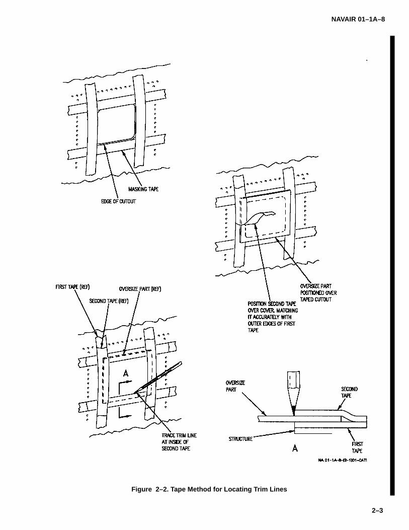
2–5. TAPE METHOD FOR LOCATING TRIM LINES.Locating trim lines for oversize parts, where there is noaccess to back side for marking, may be done withmasking tape as shown in figure 2–2 and steps below:
a. File edges of opening to be matched and edgesof oversize part to remove all burrs.
b. Align strips of masking tape along edges ofopening to form frame.
c. Put oversize part over opening and align anyexisting holes in part with their mating holes in structure.Install fasteners in as many of the full size holes as pos-sible. If part contains only pilot holes, undersize holesor no holes, tape or hold part in position.
NOTE
When replacement part is thick, inneredge of second tape will fall short ofmatching edges of cutout causing newpart to be large. Compensation for thismismatch can be made when markingedges.
d. Carefully align outer edge of second strip oftape with outer edge of first strip of tape and pull it tightlyup over oversize edge of part.
e. Mark inside edge of second tape.
f. Remove part and trim edges.
2–6. LOCATING BLIND HOLES.
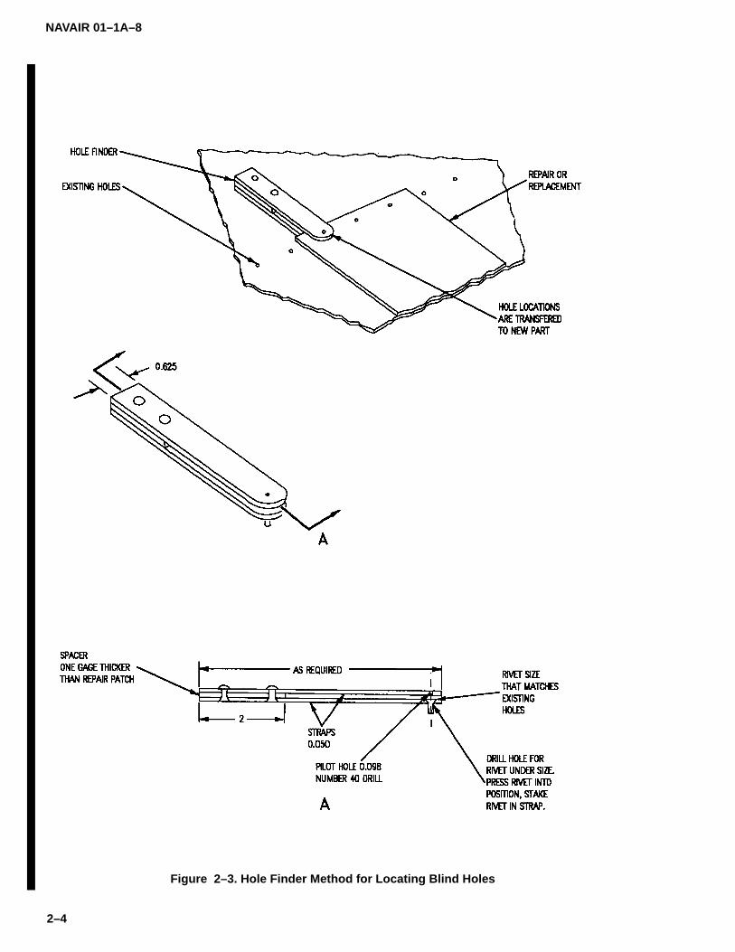
2–7. HOLE FINDER METHOD FOR LOCATINGBLIND HOLES. The hole finder may be made of variousmaterials and of special shapes and sizes to fit a specificjob. A temporary or one–time–use tool may be made ina few minutes from any scrap of hardened aluminumalloy and a rivet of desired size. It is recommended thatwhen a large number of holes are to be drilled, a prefab-ricated tool or one made of steel with steel drill bushingbe used. Locate blind holes in part using hole findermethod as shown in figure 2–3, and steps below:
a. Put new part in position.
b. Install fasteners in all existing full size holes. Ifpart has no holes or has only pilot holes or undersizeholes, tape part in position.
c. Using hole finder, inspect location of all existingpilot holes in relation to existing holes in structure beforebringing them to final size.
d. Remove part from structure and drill severalholes to final size.
e. Reinstall part with temporary fasteners. Locateand pilot drill remaining holes.

NAVAIR 01–1A–8
2–2
Figure 2–1. Skin Scribe Method for Locating Trim Lines
NAVAIR 01–1A–8
2–3
Figure 2–2. Tape Method for Locating Trim Lines
NAVAIR 01–1A–8
2–4
Figure 2–3. Hole Finder Method for Locating Blind Holes

NAVAIR 01–1A–8
2–5
CAUTION
Be careful when bringing holes to finalsize. Holes must not be drilled off center.Several intermediate size twist drillsshould be used before holes are broughtto final size. Visual inspection of holealignment should be made as drillingprogresses.
f. Remove part from structure and drill holes to fi-nal size.
g. Deburr holes.
2–8. HOLE TRANSFER PUNCH METHOD FOR LO-CATING BLIND HOLES. Blind hole transfer punchesprovide an accurate method of locating blind holes in apart. Locating blind holes in a part using blind hole trans-fer punch method may be done as shown in figure 2–4and steps below:
a. Determine hole sizes in part.
b. Select correct size blind hole transfer punchfrom table on figure.
c. Insert transfer punches into selected holes.
d. Place new part in position and lightly tap partover each transfer punch.
CAUTION
Be careful when bringing holes to finalsize. Holes must not be drilled off center.Several intermediate size twist drillsshould be used before holes are broughtto final size. Visual inspection of holealignment should be made as drillingprogresses.
e. Remove part from structure and drill holes to fi-nal size.
f. Deburr holes.
2–9. MEASURING AND SCALING METHOD FORLOCATING BLIND HOLES. With measuring and scal-ing method, blind holes are located by either measuringpredetermined amount along line passing through cen-ter of existing hole or by locating intersecting point of twolines passing through center of hole. Locating blindholes in a part using measuring and scaling method maybe done as shown in figure 2–5 and steps below:
a. Draw line through center of existing hole instructure and mark off measured distance on line fromcenterline of hole or draw two lines intersecting at centerof hole.
b. Put new part in position.
c. Install fasteners in all existing full size holes. Ifpart has no holes or has only pilot holes or undersizeholes, tape part in position.
d. Inspect location of all existing pilot holes in rela-tion to existing holes in structure by placing scale orstraight edge along uncovered part of line and projectlines on new part. Mark measured distance along pro-jected line or extend two lines until lines intersect. Ifthere are no full size holes in part, adjust new part so asmany of the pilot holes as possible are located in centerof existing holes in structure.
e. On parts that have no holes, place scale orstraight edge along uncovered part of lines of severalholes and project lines on new part. Mark measured dis-tance along projected line or extend two lines until linesintersect.
f. Center punch intersection mark and drill pilothole.
CAUTION
Be careful when bringing holes to finalsize. Holes must not be drilled off center.Several intermediate size twist drillsshould be used before holes are broughtto final size. Visual inspection of holealignment should be made as drillingprogresses.
g. Remove part from structure and drill holes to fi-nal size.
h. Reinstall part with temporary fasteners. Locateand pilot drill remaining holes.
CAUTION
Be careful when bringing holes to finalsize. Holes must not be drilled off center.Several intermediate size twist drillsshould be used before holes are broughtto final size. Visual inspection of holealignment should be made as drillingprogresses.
i. Remove part from structure and drill remainingholes to final size.

NAVAIR 01–1A–8
2–6
Figure 2–4. Hole Transfer Punch Method for Locating Blind Holes

NAVAIR 01–1A–8
2–7
Figure 2–5. Measuring and Scaling Method for Locating Blind Holes
NAVAIR 01–1A–8
2–8
j. Deburr holes.
2–10. HYDROCAL DRILL BLANKET METHOD FORLOCATING BLIND HOLES. Blind holes are located us-ing Hydrocal plaster to form a drill blanket from the partbeing repaired or replaced.
2–11. HYDROCAL PROCEDURE FOR A PANEL/DOOR. See figure 2–6 and the steps below;
a. Make aircraft safe for maintenance.
b. Remove fasteners from damaged part. Do notremove part.
c. Verify fastener holes are within tolerance.
NOTEWhen removing fasteners from indexholes, remove two fasteners, one at eachend, for each row of fastener holes to bedrilled.
d. Remove fasteners from index holes.
e. Clean surface with solvent moistened cloth.
f. Apply tape over any drain holes in work area.
g. Apply petrolatum as a parting agent over areaapproximately 3 inches on each side of fastener rows.
NOTEIf oversize fasteners were used duringmanufacturing, oversize drill bushings willbe required.
h. Install drill bushings at fastener holes and indexholes.
NOTEWashers may be used under bolt heads toget correct grip.
i. In holes requiring threaded fasteners, installbolts of correct diameter and grip into bushings. Engagenuts and tighten.
j. In holes requiring permanent fasteners, installa standard sheet metal temporary fastener through thebushing.
k. Mix hydrocal and water, 2 parts hydrocal to 1part water, to a putty consistency.
NOTEHydrocal mixture should be approximate-ly 0.50 inches thick and 2 inches on eitherside of bushings.
l. Apply hydrocal mixture to surface around bush-ings, add cheesecloth as reinforcing fiber, and applyadditional hydrocal over cheesecloth.
m. Clean excess hydrocal from fastener heads.
n. Allow hydrocal mixture to cure approximately 2hours at room temperature or accelerate cure at 190 de-grees plus or minus 10 degrees for 1 hour.
o. Remove all fasteners from bushings.
p. Carefully remove hydrocal drill blanket.
q. Remove damaged part.
r. Clean area as required.
s. Verify holes in mating structure are within toler-ance.
t. Trim replacement part, being careful to main-tain required gap and mismatch limits.
u. Temporarily secure replacement part in place.
v. Position hydrocal drill blanket on surface.
w. Align index holes.
x. Insert fasteners through index hole bushingsand tighten.
CAUTION
To avoid damage to hardware, limit depthof drilling.
y. Drill fastener holes as required.
z. Remove fasteners from drill blanket.
aa. Remove drill blanket.
ab. Deburr and countersink holes as required.
ac. Reinstall index hole fasteners.
ad. Seal replacement part, as required.
ae. Install fasteners attaching replacement part.
af. Touch up finish system as required.
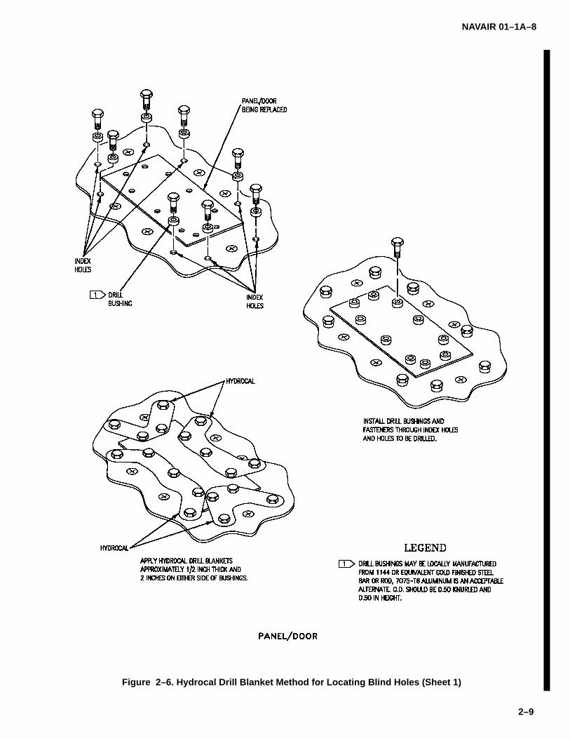
NAVAIR 01–1A–8
2–9
Figure 2–6. Hydrocal Drill Blanket Method for Locating Blind Holes (Sheet 1)

NAVAIR 01–1A–8
2–10
Figure 2–6. Hydrocal Drill Blanket Method for Locating Blind Holes (Sheet 2)

NAVAIR 01–1A–8
2–11
Figure 2–6. Hydrocal Drill Blanket Method for Locating Blind Holes (Sheet 3)
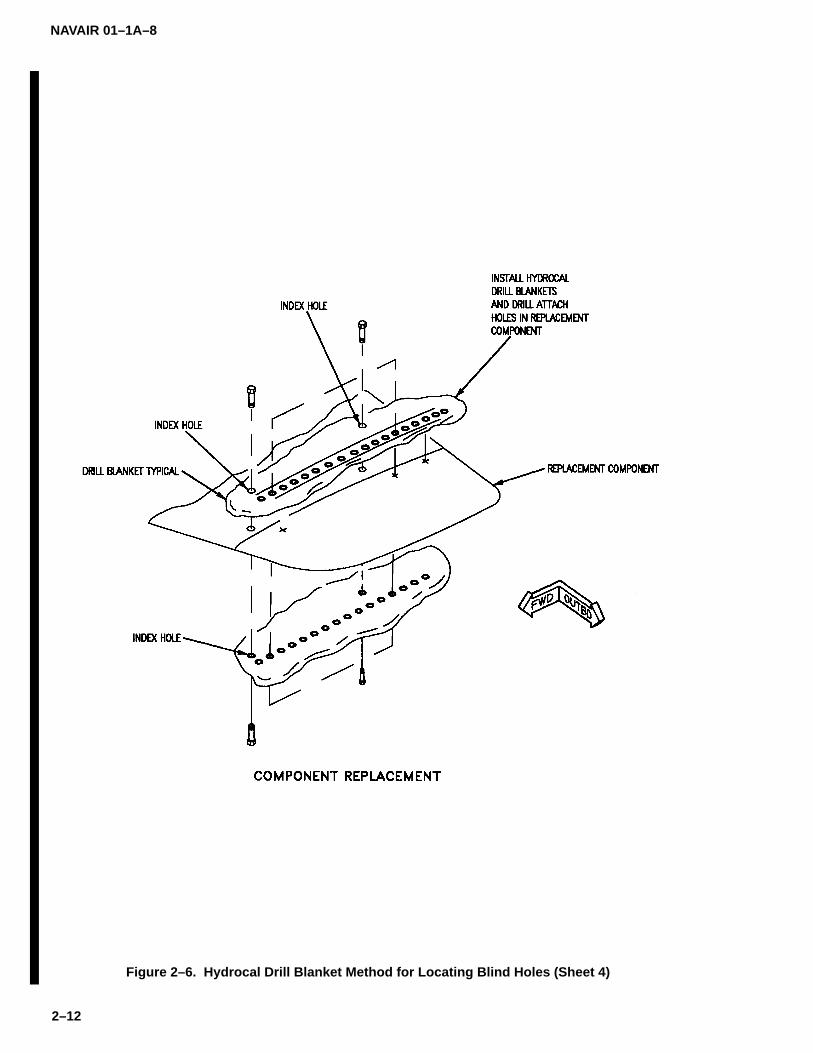
NAVAIR 01–1A–8
2–12
Figure 2–6. Hydrocal Drill Blanket Method for Locating Blind Holes (Sheet 4)
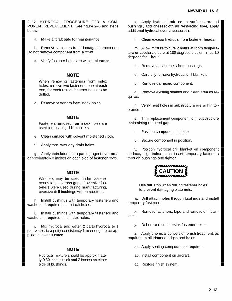
NAVAIR 01–1A–8
2–13
2–12. HYDROCAL PROCEDURE FOR A COM-PONENT REPLACEMENT. See figure 2–6 and stepsbelow;
a. Make aircraft safe for maintenance.
b. Remove fasteners from damaged component.Do not remove component from aircraft.
c. Verify fastener holes are within tolerance.
NOTEWhen removing fasteners from indexholes, remove two fasteners, one at eachend, for each row of fastener holes to bedrilled.
d. Remove fasteners from index holes.
NOTEFasteners removed from index holes areused for locating drill blankets.
e. Clean surface with solvent moistened cloth.
f. Apply tape over any drain holes.
g. Apply petrolatum as a parting agent over areaapproximately 3 inches on each side of fastener rows.
NOTEWashers may be used under fastenerheads to get correct grip. If oversize fas-teners were used during manufacturing,oversize drill bushings will be required.
h. Install bushings with temporary fasteners andwashers, if required, into attach holes.
i. Install bushings with temporary fasteners andwashers, if required, into index holes.
j. Mix hydrocal and water, 2 parts hydrocal to 1part water, to a putty consistency firm enough to be ap-plied to lower surface.
NOTEHydrocal mixture should be approximate-ly 0.50 inches thick and 2 inches on eitherside of bushings.
k. Apply hydrocal mixture to surfaces aroundbushings, add cheesecloth as reinforcing fiber, applyadditional hydrocal over cheesecloth.
l. Clean excess hydrocal from fastener heads.
m. Allow mixture to cure 2 hours at room tempera-ture or accelerate cure at 190 degrees plus or minus 10degrees for 1 hour.
n. Remove all fasteners from bushings.
o. Carefully remove hydrocal drill blankets.
p. Remove damaged component.
q. Remove existing sealant and clean area as re-quired.
r. Verify rivet holes in substructure are within tol-erance.
s. Trim replacement component to fit substructuremaintaining required gap.
t. Position component in place.
u. Secure component in position.
v. Position hydrocal drill blanket on componentsurface, align index holes, insert temporary fastenersthrough bushings and tighten.
CAUTION
Use drill stop when drilling fastener holesto prevent damaging plate nuts.
w. Drill attach holes through bushings and installtemporary fasteners.
x. Remove fasteners, tape and remove drill blan-kets.
y. Deburr and countersink fastener holes.
z. Apply chemical conversion brush treatment, asrequired, to all trimmed edges and holes.
aa. Apply sealing compound as required.
ab. Install component on aircraft.
ac. Restore finish system.

NAVAIR 01–1A–8
2–14
2–13. DRILLING.
2–14. DRILLING EQUIPMENT FOR METALLICSTRUCTURES. Holes may be drilled in metallic struc-tures using a light pneumatic drill or hand drill with astraight shank drill bit. Table 2–1 specifies twist drill sizesranging from 1/2–inch to number 80. Table 2–2 providesstandard drilled hole tolerances. Refer to Section III fordrill sizes for specific types of rivets.
Metallic Dust 1
2–15. DRILLING METALLIC STRUCTURES. Use thefollowing procedure for drilling holes in metallic struc-tures:
a. When possible, centerpunch all hole locationsdeep enough to prevent the drill bit from slipping out ofposition. Backup the structure with a bucking bar whencenter punching (see paragraph 2–50).
b. Drill pilot holes at all hole locations using a #40drill bit (0.098–inch).
c. Select a properly ground drill bit (see Figure2–7).
d. Place drill in centerpunch, hold perpendicular tothe surface, apply a light steady pressure, and actuatedrill.
NOTE
Do not push drill through the material; al-low the drill to do the cutting.
e. Remove burrs with a countersink or file. Cleanaway all metal chips.
2–16. DRILLING GRAPHITE/EPOXY LAMINATES.Use the following procedure for graphite/epoxy lami-nates:
Graphite/Epoxy Laminates 2
a. Backup and Clamping. Backup composite ma-terials when drilling to prevent delamination, splintering,or fraying. Fiberboard, wood, and fiberglass are ade-quate backup materials.
NOTEWhenever possible, securely clamp thematerials to be drilled to eliminate gapsbetween the sheets.
b. Drill Selection. Carbide–tipped or solid carbidedrills are recommended for drilling graphite/epoxy lami-nates. Cobalt high–speed steel drills may be used, butrequire sharpening more often. For drilling throughcomposite materials only, a flat flute or spade drill bitdriven by an air–driven, high–speed drill is recom-mended. Single–flute drill bits and spade drill bits (seeFigures 2–8 and 2–9) are designed to cut solid lami-nates and honeycomb sandwich panels reinforced withKevlar 49. Both provide a sloped cutting edge for agentle action to sever fibers in the laminate structure.Tables 2–3 and 2–4 list recommended drill speeds andfeed rates.
NOTEWhen drilling a combination of laminateand aluminum or titanium substructure,use a twist drill. Vacuum after drilling toclear away filings.
c. Equipment Selection. Drill graphite/epoxy lami-nates using portable hand equipment or positive powerfeed equipment. Surge control (feed–rate limiting) de-vices should be used with hand–held equipment. Usedrill bushings, drill stands, and templates, when pos-sible, to maintain hole alignment and location. Vacuumdust collectors shall be used to control air quality.
CAUTION
Exercise caution when drilling near fueltanks to prevent dust or coolant contami-nation of the cells.

NAVAIR 01–1A–8
2–15
Table 2–1. Twist Drill Sizes
SIZE DECIMAL SIZE DECIMAL SIZE DECIMAL SIZE DECIMAL1/2 .5000 G .2610 23 .1540 1/16 .0625
31/64 .4844 F .2570 24 .1520 53 .059515/32 .4687 1/4 .2500 25 .1495 54 .055029/64 .4531 D .2460 26 .1470 55 .05207/16 .4375 C .2420 27 .1440 3/64 .046927/64 .4219 B .2380 9/64 .1406 56 .0465
Z .4130 15/64 .2344 28 .1405 57 .043013/32 .4062 A .2340 29 .1360 58 .0420
Y .4040 1 .2280 30 .1285 59 .0410X .3970 2 .2210 1/8 .1250 60 .0400
25/64 .3906 7/32 .2188 31 .1200 61 .0390W .3860 3 .2130 32 .1160 62 .0380V .3770 4 .2090 33 .1130 63 .0370
3/8 .3750 5 .2055 34 .1110 64 .0360U .3680 6 .2040 35 .1100 65 .0350
23/64 .3594 13/64 .2031 7/64 .1094 66 .0330T .3580 7 .2010 36 .1065 67 .0320S .3480 8 .1990 37 .1040 1/32 .0312
11/32 .3438 9 .1960 38 .1015 68 .0310R .3390 10 .1935 39 .0995 69 .0292Q .3320 11 .1910 40 .0980 70 .0280
21/64 .3281 12 .1890 41 .0960 71 .0260P .3230 3/16 .1875 3/32 .0938 72 .0250O .3160 13 .1850 42 .0935 73 .0240
5/16 .3125 14 .1820 43 .0890 74 .0225N .3020 15 .1800 44 .0860 75 .0210
19/64 .2969 16 .1770 45 .0820 76 .0200M .2950 17 .1730 46 .0810 77 .0180L .2900 11/64 .1719 47 .0785 78 .0160
9/32 .2812 18 .1695 5/64 .0781 1/64 .0156K .2810 19 .1660 48 .0760 79 .0145J .2770 20 .1610 49 .0730 80 .0135I .2720 21 .1590 50 .0700H .2660 22 .1570 51 .0670
17/64 .2656 5/32 .1562 52 .0635
Table 2–2. Standard Drilled Hole Tolerances
NOMINAL HOLE DIAMETER HOLE TOLERANCE
.0135 – .125 +.004 –.001
.126 – .250 +.005 –.001
.251 – .500 +.006 –.001
.501 – .750 +.008 –.001
.751 – 1.000 +.010 –.001
1.000 –2.000 +.012 –.001

NAVAIR 01–1A–8
2–16
Figure 2–7. Drilling for Rivets
Figure 2–8. Single Flute Drill
d. Coolants. A high–pressure spray mist of wateror water–based coolant should be used when drillinggraphite/epoxy laminates alone or in combination withmetallic substructures. Do not use coolant when drillingbonded honeycomb or foam structure. Holes may bedrilled without coolant if temperature–indicating devicesare used to prevent overheating.
2–17. TOOL MAINTENANCE. Dull or chipped drills af-fect hole quality and dimensions and may causeoverheating of the material. Carbide flat flute or spacedrills normally require sharpening after drilling 40 to 60holes in graphite/epoxy laminates under normal operat-ing conditions. Carbide twist drills used to drill combinedlaminates and metallic substructure normally requiresharpening after 30 to 45 holes.
2–18. HAND DRILLING GRAPHITE/EPOXY LAM-INATES. Repair operations often require drillinggraphite/epoxy laminates using hand–held portableequipment. To obtain high quality holes, use portabledrill stands or drill guides. If available, drill motorsequipped with feed–rate limiting surge control are rec-ommended. Maintain a steady pressure to keep the drillcutting continuously. When drilling without depth sen-sors, gradually reduce pressure and avoid tilting thedrill, impacting the chuck into the work, or driving the drillpoint into an unseen material. Ensure the drill is turningbefore it contacts the surface.
CAUTION
As the drill exits the material, reduce pres-sure to prevent splintering of fibers on theback face of the laminate. The drill shallbe turning when backing out of the com-pleted hole.
2–19. DRILLING BORON/EPOXY LAMINATES. Bo-ron/epoxy laminates or hybrid laminates containingboron/epoxy are much more difficult to drill than graph-ite/epoxy laminates. Diamond cutting tools are requiredfor drilling boron/epoxy laminates. Coolant shall beused since diamond cutting tools are heat sensitive.Cutting tools may be used in either conventional orrotary ultrasonic drilling equipment. The combination ofwater pressure and ultrasonic excitation to the drillspindle has been found to give high cutting rates and tominimize tool wear and breakage. Operating parame-ters for metal–matrix diamond tools used for drillingboron/epoxy laminates are provided in Table 2–5.
Figure 2–9. Spade Drill for Composites

NAVAIR 01–1A–8
2–17
Table 2–3. Speed and Feed Rates for Drilling Graphite/Epoxy Laminates*
DRILLING REAMING (IF REQUIRED)HOLE DIAMETER,
INCH MAXSPEED, RPM
FEED RATE,SEC/IN. SPEED, RPM
FEED RATE,SEC/IN.
5/32 3000 15 to 30 3000 15 to 30
3/16 3000 15 to 30 3000 15 to 30
1/4 3000 15 to 30 3000 15 to 30
5/16 1800 15 to 30 1800 15 to 30
3/8 1000 15 to 30 1800 15 to 30
* For carbide flat shank (spade) drills or carbide straight shank reamers, used with coolant and adequate backup support.
Table 2–4. Speed and Feed Rates for Drilling Graphite/Epoxy Laminateswith Metallic Substructure*
DRILLING REAMING (IF REQUIRED)MATERIALS
HOLES DIA, INCH MAX SPEED, RPMWITH COOLANT
FEED RATE, (1)(IN./REVOLUTION)
MAX SPEED, RPMWITH COOLANT
FEED RATE, (1)(IN./REVOLUTION)
Laminate 5/32withAluminum 3/16
1/45/163/8
4000
4000300024002000
0.002
0.0020.0020.0020.002
4000
4000300024002000
0.006
0.0060.0060.0060.006
Laminate 5/32withTitanium 3/16
1/45/163/8
750
600450350300
0.002
0.0020.0020.0020.002
750
600450350300
0.006
0.0060.0060.0060.006
Graphite/ 1/4EpoxyLaminate 5/16withTitanium 3/8
1100
1100
1100
0.0005
0.0005
0.0005
Do not ream —
Graphite/ 1/4Epoxy 5/16LaminatewithSteel 3/8
450450
450
0.00050.0005
0.0005
Do not ream —
NOTE: Numbers are recommended feed rates for positive feed drill motors. For air motors adjust the hydrauliccheck valves to obtain 30 to 45 sec/inch.
* For carbide twist drills or carbide straight shank reamers, used with coolant and adequatebackup support.
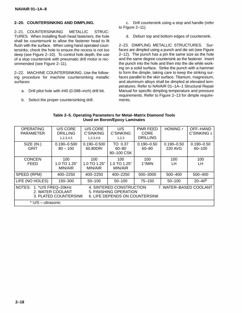
NAVAIR 01–1A–8
2–18
2–20. COUNTERSINKING AND DIMPLING.
2–21. COUNTERSINKING METALLIC STRUC-TURES. When installing flush head fasteners, the holeshall be countersunk to allow the fastener head to fitflush with the surface. When using hand operated coun-tersinks, check the hole to ensure the recess is not toodeep (see Figure 2–10). To control hole depth, the useof a stop countersink with pneumatic drill motor is rec-ommended (see Figure 2–11).
2–22. MACHINE COUNTERSINKING. Use the follow-ing procedure for machine countersinking metallicsurfaces:
a. Drill pilot hole with #40 (0.098–inch) drill bit.
b. Select the proper countersinking drill.
c. Drill countersink using a stop and handle (referto Figure 2–11).
d. Deburr top and bottom edges of countersink.
2–23. DIMPLING METALLIC STRUCTURES. Sur-faces are dimpled using a punch and die set (see Figure2–12). The punch has a pin the same size as the holeand the same degree countersink as the fastener. Insertthe punch into the hole and then into the die while work-ing on a solid surface. Strike the punch with a hammerto form the dimple, taking care to keep the striking sur-faces parallel to the skin surface. Titanium, magnesium,and aluminum alloys shall be dimpled at elevated tem-peratures. Refer to NAVAIR 01–1A–1 Structural RepairManual for specific dimpling temperature and pressurerequirements. Refer to Figure 2–13 for dimple require-ments.
Table 2–5. Operating Parameters for Metal–Matrix Diamond ToolsUsed on Boron/Epoxy Laminates
OPERATINGPARAMETER
U/S COREDRILLING
1,2,3,4,5
U/S COREC’SINKING
1,2,3,4,6
U/SC’SINKING
1,2,3
PWR FEEDCORE
DRILLING
HONING 7 OFF–HANDC’SINKING 3
SIZE (IN.)GRIT
0.190–0.50080 – 100
0.190–0.50060.80DR/
TO 0.3760–80
80–100 CSK
0.190–0.5060–80
0.190–0.50220 AVG
0.190–0.5060–100
CONCENFEED
1001.0 TO 1.25”
MIN/AIR
1001.0 TO 1.25”
MIN/AIR
1001.0 TO 1.25”
MIN/AIR
1001”/MIN
100LH
100LH
SPEED (RPM) 400–2250 400–2250 400–2250 500–3000 500–400 500–400
LIFE (NO HOLES) 150–300 50–100 50–100 75–150 50–100 20–405
NOTES: 1. *U/S FREQ–20kHz 4. SINTERED CONSTRUCTION 7. WATER–BASED COOLANT2. WATER COOLANT 5. FINISHING OPERATION3. PLATED COUNTERSINK 6. LIFE DEPENDS ON COUNTERSINK
* U/S – ultrasonic

NAVAIR 01–1A–8
2–19
CORRECT DEGREEAND DEPTH
COUNTERSINKTOO SHALLOW
COUNTERSINKTOO DEEP
WRONG DEGREECOUNTERSINK USED
Figure 2–10. Countersinking for Rivets
Figure 2–11. Micro Stop Countersink Units
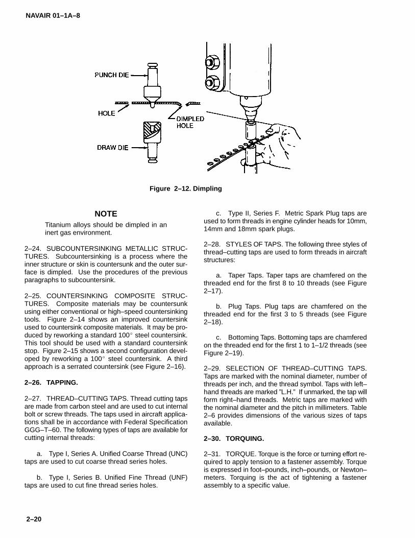
NAVAIR 01–1A–8
2–20
Figure 2–12. Dimpling
NOTETitanium alloys should be dimpled in aninert gas environment.
2–24. SUBCOUNTERSINKING METALLIC STRUC-TURES. Subcountersinking is a process where theinner structure or skin is countersunk and the outer sur-face is dimpled. Use the procedures of the previousparagraphs to subcountersink.
2–25. COUNTERSINKING COMPOSITE STRUC-TURES. Composite materials may be countersunkusing either conventional or high–speed countersinkingtools. Figure 2–14 shows an improved countersinkused to countersink composite materials. It may be pro-duced by reworking a standard 100� steel countersink.This tool should be used with a standard countersinkstop. Figure 2–15 shows a second configuration devel-oped by reworking a 100� steel countersink. A thirdapproach is a serrated countersink (see Figure 2–16).
2–26. TAPPING.
2–27. THREAD–CUTTING TAPS. Thread cutting tapsare made from carbon steel and are used to cut internalbolt or screw threads. The taps used in aircraft applica-tions shall be in accordance with Federal SpecificationGGG–T–60. The following types of taps are available forcutting internal threads:
a. Type I, Series A. Unified Coarse Thread (UNC)taps are used to cut coarse thread series holes.
b. Type I, Series B. Unified Fine Thread (UNF)taps are used to cut fine thread series holes.
c. Type II, Series F. Metric Spark Plug taps areused to form threads in engine cylinder heads for 10mm,14mm and 18mm spark plugs.
2–28. STYLES OF TAPS. The following three styles ofthread–cutting taps are used to form threads in aircraftstructures:
a. Taper Taps. Taper taps are chamfered on thethreaded end for the first 8 to 10 threads (see Figure2–17).
b. Plug Taps. Plug taps are chamfered on thethreaded end for the first 3 to 5 threads (see Figure2–18).
c. Bottoming Taps. Bottoming taps are chamferedon the threaded end for the first 1 to 1–1/2 threads (seeFigure 2–19).
2–29. SELECTION OF THREAD–CUTTING TAPS.Taps are marked with the nominal diameter, number ofthreads per inch, and the thread symbol. Taps with left–hand threads are marked ”L.H.” If unmarked, the tap willform right–hand threads. Metric taps are marked withthe nominal diameter and the pitch in millimeters. Table2–6 provides dimensions of the various sizes of tapsavailable.
2–30. TORQUING.
2–31. TORQUE. Torque is the force or turning effort re-quired to apply tension to a fastener assembly. Torqueis expressed in foot–pounds, inch–pounds, or Newton–meters. Torquing is the act of tightening a fastenerassembly to a specific value.

NAVAIR 01–1A–8
2–21
Figure 2–13. Dimple Appearance and Requirements
Figure 2–14. Countersink for Composites
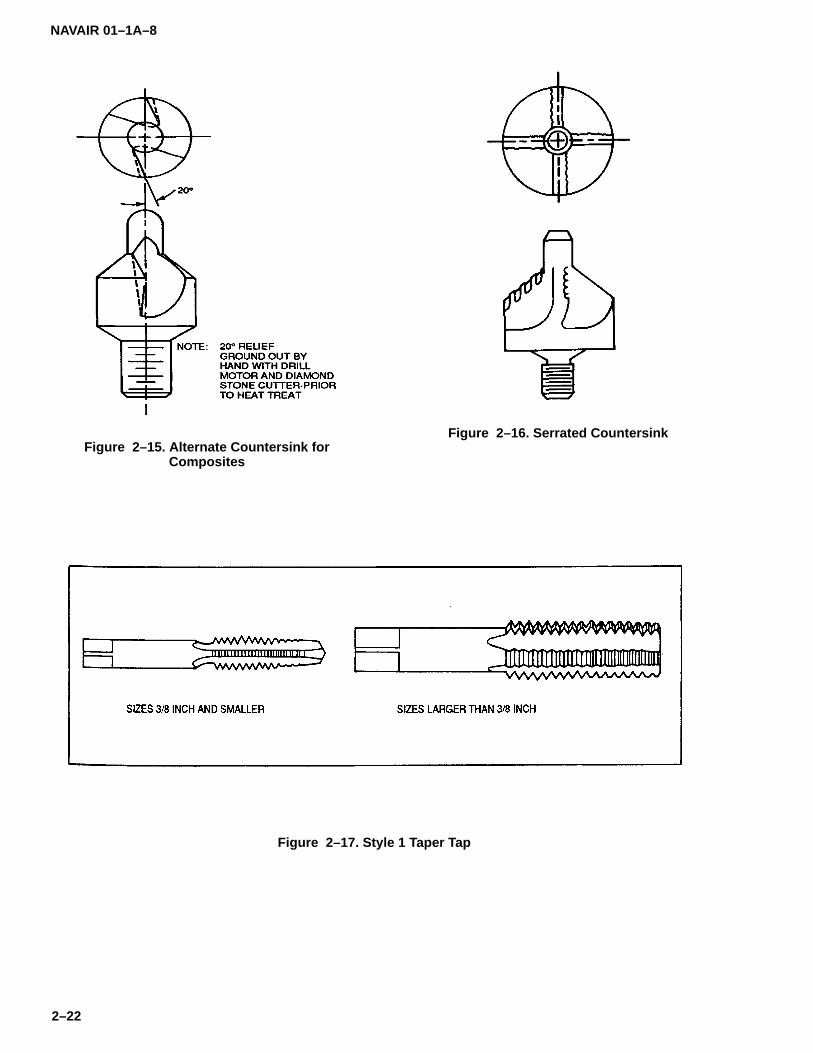
NAVAIR 01–1A–8
2–22
Figure 2–15. Alternate Countersink forComposites
Figure 2–16. Serrated Countersink
Figure 2–17. Style 1 Taper Tap

NAVAIR 01–1A–8
2–23
Figure 2–18. Style 2 Plug Tap
Figure 2–19. Style 3 Bottoming Tap
2–32. FORCES. Two separate forces, tension and tor-sion, are exerted on a fastener when it is tightened.Tension is the desired stress and torsion is the forcecaused by friction. Approximately 50% of the appliedtorque is absorbed overcoming friction (torsion) on theworking surfaces of the fastener and 40% is absorbedby thread friction. Thus, only about 10% of the torqueis applied to bolt tension (pre–load).
2–33. VARIABLES AFFECTING TORQUE. Severalvariables must be taken into consideration when deter-mining the amount of torque to apply to a given fastener.Standard torque charts are developed for dry, un–platedconditions. Surface variables to be taken into accountfor each specific application include thread roughness,lubrication, hardening, scale, paint, and plating. Torquevalues may also vary among fastener manufacturers.
NOTE
When specific torque values are includedin a technical manual for a specific item,those values shall be used.
2–34. TORQUING NUTS AND BOLTS. Failure inaerospace equipment often occurs due to improper
torquing of fasteners. The nut shall always be torquedwhen used with a bolt or screw. If no nut is used, the boltor screw may be torqued. Recommended torque valuesare listed in Table 2–7. These values shall be used un-less the TMS for the specific aircraft requires a specifictorque value. Threads shall be dry and oil–free whentorqued in accordance with Table 2–7. When castle nutsare being installed, torque the nut to the minimum valueand tighten to the next locking position.
CAUTION
Do not exceed the maximum torque val-ue. Overstressing or premature failure ofthe nut, bolt, or screw may result.
2–35. TORQUE WRENCHES. The following styles oftorque wrenches may be used in aircraft applications(see Figure 2–20):
a. Indicating Torque Wrenches. These wrenchesmeasure changes in applied torque through a deflectingmember (see Figure 2–20). A dial or digital readout islocated below the handle to permit convenient and ac-curate readings. Indicating torque wrenches operate inclockwise and counterclockwise directions.

NAVAIR 01–1A–8
2–24
Table 2–6. Dimensions of Series A, B and F Taps
SCREW GAGENO. OR
DIAMETER
THREADS PER INCH A B
NUMBEROF
FLUTES
OVERALLLENGTH
INCH
THREADLENGTH
INCH
SQUARELENGTH
INCH
SHANKDIAMETER
INCH
SQUARESIZEINCH
0 80 2 1–5/8 5/16 3/16 .141 .110
1 64 72 2 1–11/16 3/8 3/16 .141 .110
2 56 64 3 1–3/4 7/16 3/16 .141 .110
3 48 56 3 1–13/16 1/2 3/16 .141 .110
4 40 48 3 1–7/8 9/16 3/16 .141 .110
5 40 44 3 1–15/16 5/8 3/16 .141 .110
6 32 40 3 2 11/16 3/16 .141 .110
8 32 36 4 2–1/8 3/4 1/4 .168 .131
19 24 32 4 2–3/8 7/8 1/4 .194 .152
12 24 28 4 2–3/8 15/16 9/32 .220 .165
1/4 20 28 4 2–1/2 1 5/16 .255 .191
5/16 18 24 4 2–23/32 1–1/8 3/8 .318 .238
3/8 16 24 4 2–15/16 1–1/4 7/16 .381 .286
7/16 14 20 4 3–5/32 1–7/16 13/32 .323 .242
1/2 13 20 4 3–3/8 1–21/32 7/16 .367 .275
9/16 12 18 4 3–19/32 1–21/32 1/2 .429 .322
5/8 11 18 4 3–13/16 1–13/16 9/16 .480 .360
3/4 10 16 4 4–1/4 2 11/16 .590 .442
7/8 9 14 4 4–11/16 2–7/32 3/4 .697 .523
1 8 12 4 5–1/8 2–1/2 13/16 .800 .600
1–1/8 7 12 4 5–7/16 2–9/16 7/8 .896 .672
1–1/4 7 12 4* 5–3/4 2–9/16 1 1.021 .766
1–3/8 6 12 4* 6–1/16 3 1–1/16 1.108 .831
1–1/2 6 12 4* 6–3/8 3 1–1/8 1.233 .925
1–3/4 5 12 6 7 3–3/16 1–1/4 1.430 1.072
2 4–1/2 12 6 7–5/8 3–9/16 1–3/8 1.644 1.233
SPARK PLUG TAPS
TAPDIAMETER
PITCH(mm)
NUMBEROF
FLUTES
OVERALLLENGTH
THREADLENGTH
SQUARELENGTH
SHANK DI-AMETER
SQUARESIZE
10 1.00 4 74.6 mm 31.8 mm 9.52 mm 7.77 mm 5.82 mm
14 1.25 4 91.3 mm 42.1 mm 12.70 mm 10.90 mm 8.18 mm
18 1.50 4 102.4 mm 46.0 mm 15.87 mm 13.77 mm 10.31 mm
* Series B taps shall have 6 flutes in these sizes.

NAVAIR 01–1A–8
2–25
Table 2–7. Recommended Torque Values
NOTE Those tables are applicable whenever torquevalues are not called out in a specific procedure.
• To convert to foot–pounds, divide inch–pounds by 12.
• Threads must be free from grease or oil, except forcorrosion–resistant steel bolts. Lubrication changesthe torque value, and overtorquing will result.
• Lubricate corrosion–resistant steel bolts with an anti–seize compound. Corrosion–resistant steel bolts andnuts must be used together. Use shear nut torquevalues when tightening these bolts.
• Use lower torque value for cotter pin or lockwiresecured nuts. Obtain alignment of slot and hole byincreasing torque only.
• Use higher torque values for torquing from head end.A tolerance of 10 percent above the higher torquelimit must not be exceeded.
• Use torque values shown for tension–type nuts when* using heat–treated corrosion–resistant steel nuts.
For nonheat–treated corrosion–resistant steel nuts,use torque values for shear–type nuts.
• The use of shear–type nuts requires the use of the† torque values given for shear–type nuts.
• NAS1292 and NAS1322 series shear pins used with‡ NAS1287 and NAS1288 nuts shall be considered in
this category and torqued accordingly.

NAVAIR 01–1A–8
2–26
b. Setting Torque Wrenches. These wrenchescompare the applied load to a self–contained standard(see Figure 2–20). Reset is automatic upon release ofload application.
c. Limiting Torque Wrenches. These wrenches re-lease a drive tang at a pre–selected torque value. Resetis automatic. Limiting torque wrenches are availablewith a screwdriver (see Figure 2–20) or ”T” handle grip.
2–36. USE OF TORQUE WRENCHES. When adapt-ers or extensions are used, the difference in mechanicalvalue must be considered when determining the dialreading which will give the specified torque at the nut be-ing tightened. Use the following procedure to determinethe dial reading or torque setting to achieve the desiredtorque (see Figure 2–21):
S = Handle Setting
T = Torque Applied at End of Adapter(Desired Torque)
La = Length of Handle in Inches
Ea = Length of Extension in Inches
If it is desired to exert 100 inch–pounds at the end of thewrench and extension, when La equals 12 inches and Eaequals 6 inches, it is possible to determine the handlesetting by making the following calculation:
S = (T x La)/(La + Ea)
T = (100 x 12)/(12 + 6)
La = 1200/18
Ea = 66.6 inch–pounds
Whenever possible, attach the extension in line with thetorque wrench. When it is necessary to attach the exten-sion at an angle to the torque wrench as shown in Figure2–22, the effective length of the assembly will be La + Eb(see Figure 2–22). In this case, substitute the length Ebfor the length Ea in the previous formula.
2–37. PRECAUTIONS. Adhere to the following pre-cautions when using torque wrenches:
a. An extension shall not be used on the grip endof a torque wrench.
b. Unless otherwise directed, torque wrenchesshall not be used to break loose previously tightenedbolts.
c. A torque wrench shall not be used to apply agreater amount of torque than the rated capacity of thetool.
d. Do not attempt to change the setting when thehandle is in a locked position.
e. Do not attempt to use an extension on the endof a torque wrench at an angle less than 90�.
2–38. SAFETY WIRING AND COTTER PINS.
2–39. SAFETY WIRING. This section provides infor-mation on securing screws, nuts, bolts, oil caps, draincocks, valves, turnbuckles, etc., with safety wire andcotter pins.
2–40. SHEAR WIRING. Shear wiring is used in ap-plications where it is necessary to purposely shear thewire to permit operation or actuation of emergency de-vices. Copper wire is used in these applications, whichinclude the operation of ejection seats.
2–41. SAFETY WIRE MATERIALS. Table 2–8 listsavailable safety wire materials and the applications forwhich they are designed. Monel safety wire is used inapplications up to 700�F. Inconel safety wire is used inapplications up to 1500�F. Aluminum alloy safety wireis used to secure magnesium fasteners and parts. Car-bon steel wire is used in low temperature generalapplications. CRES wire is used in applications wherenon–magnetic and/or heat–resistant properties are de-sired. Copper wire is used in shear applications asspecified in paragraph 2–40.
2–42. SAFETY WIRING PROCEDURE. Use the fol-lowing procedure for safety wiring parts together (seeFigures 2–23 and 2–24):
CAUTION
Do not reuse safety wire.
a. Ensure components to be wired have beenproperly torqued and the wiring holes are in the samerelative position. Do not over–torque or loosen compo-nents to obtain proper hole alignment. Proper alignmentshould be possible when the components are torquedwithin the specified limits.
b. To prevent damaging the safety wire when tight-ening, grasp the wire at the end with pliers. Replacekinked or otherwise damaged safety wire. Cut off theloose end with a wire cutters leaving a 1/2–inch to5/8–inch tail.

NAVAIR 01–1A–8
2–27
Figure 2–20. Torque Wrenches
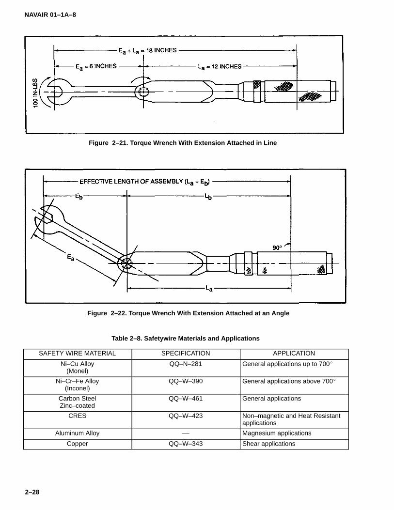
NAVAIR 01–1A–8
2–28
Figure 2–21. Torque Wrench With Extension Attached in Line
Figure 2–22. Torque Wrench With Extension Attached at an Angle
Table 2–8. Safetywire Materials and Applications
SAFETY WIRE MATERIAL SPECIFICATION APPLICATION
Ni–Cu Alloy(Monel)
QQ–N–281 General applications up to 700�
Ni–Cr–Fe Alloy(Inconel)
QQ–W–390 General applications above 700�
Carbon SteelZinc–coated
QQ–W–461 General applications
CRES QQ–W–423 Non–magnetic and Heat Resistantapplications
Aluminum Alloy � Magnesium applications
Copper QQ–W–343 Shear applications

NAVAIR 01–1A–8
2–29
Figure 2–23. Securing Screws, Nuts, Bolts, and Snap Rings

NAVAIR 01–1A–8
2–30
Figure 2–24. Safetywiring Procedures (Sheet 1 of 4)

NAVAIR 01–1A–8
2–31
Figure 24. Safetywiring Procedures (Sheet 2 of 4)
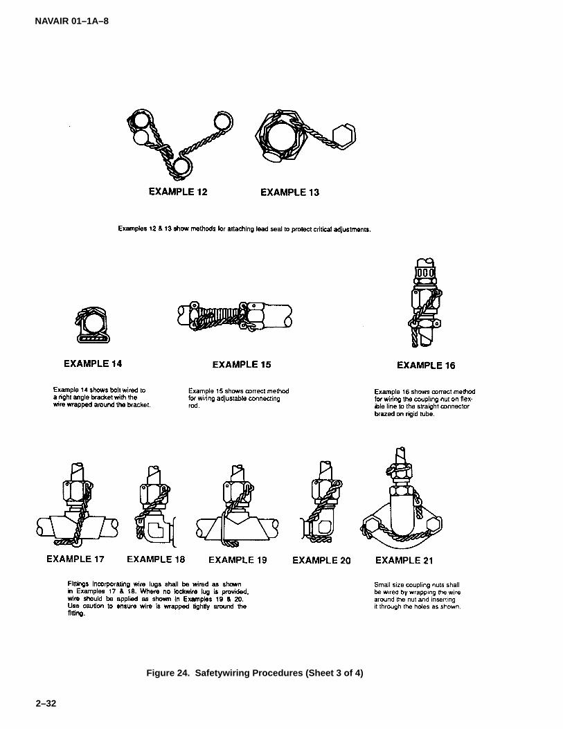
NAVAIR 01–1A–8
2–32
Figure 24. Safetywiring Procedures (Sheet 3 of 4)

NAVAIR 01–1A–8
2–33
Figure 24. Safetywiring Procedures (Sheet 4 of 4)
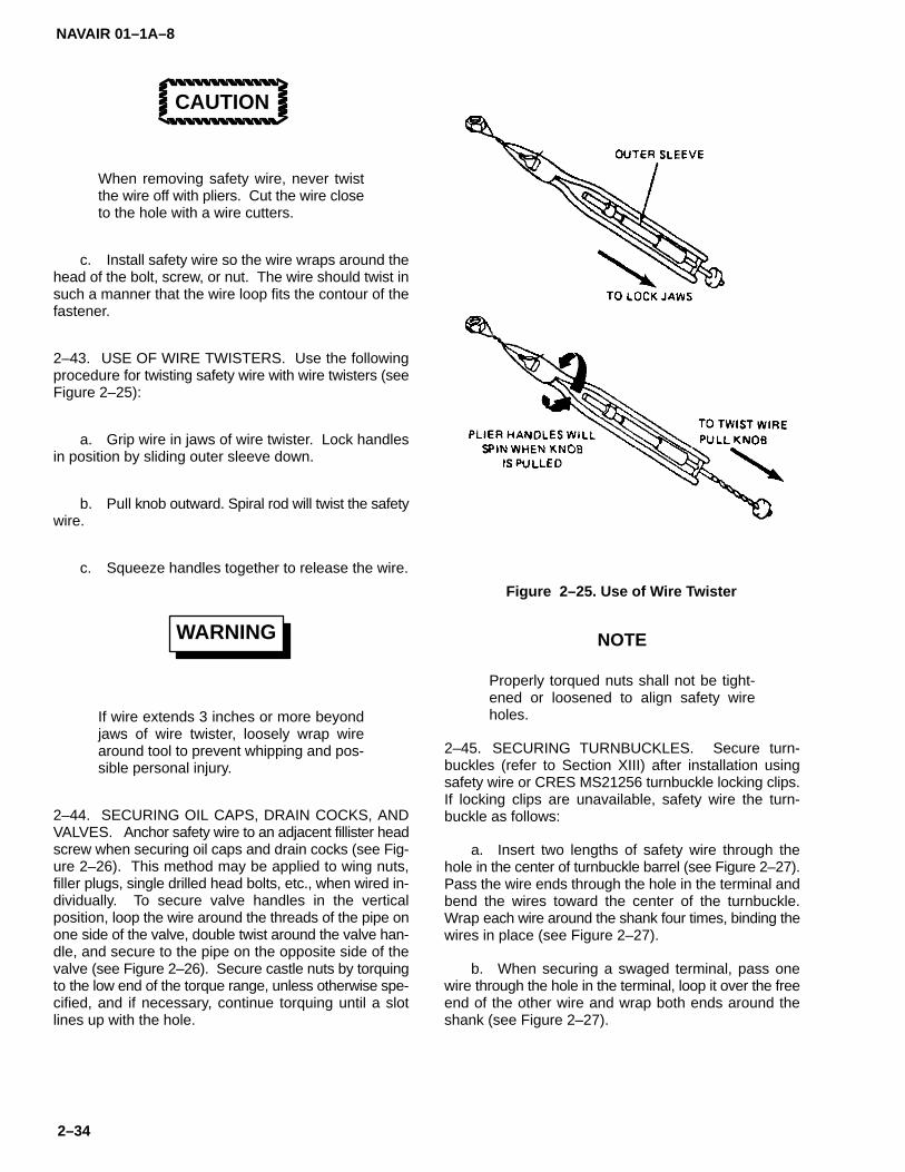
NAVAIR 01–1A–8
2–34
CAUTION
When removing safety wire, never twistthe wire off with pliers. Cut the wire closeto the hole with a wire cutters.
c. Install safety wire so the wire wraps around thehead of the bolt, screw, or nut. The wire should twist insuch a manner that the wire loop fits the contour of thefastener.
2–43. USE OF WIRE TWISTERS. Use the followingprocedure for twisting safety wire with wire twisters (seeFigure 2–25):
a. Grip wire in jaws of wire twister. Lock handlesin position by sliding outer sleeve down.
b. Pull knob outward. Spiral rod will twist the safetywire.
c. Squeeze handles together to release the wire.
WARNING
If wire extends 3 inches or more beyondjaws of wire twister, loosely wrap wirearound tool to prevent whipping and pos-sible personal injury.
2–44. SECURING OIL CAPS, DRAIN COCKS, ANDVALVES. Anchor safety wire to an adjacent fillister headscrew when securing oil caps and drain cocks (see Fig-ure 2–26). This method may be applied to wing nuts,filler plugs, single drilled head bolts, etc., when wired in-dividually. To secure valve handles in the verticalposition, loop the wire around the threads of the pipe onone side of the valve, double twist around the valve han-dle, and secure to the pipe on the opposite side of thevalve (see Figure 2–26). Secure castle nuts by torquingto the low end of the torque range, unless otherwise spe-cified, and if necessary, continue torquing until a slotlines up with the hole.
Figure 2–25. Use of Wire Twister
NOTE
Properly torqued nuts shall not be tight-ened or loosened to align safety wireholes.
2–45. SECURING TURNBUCKLES. Secure turn-buckles (refer to Section XIII) after installation usingsafety wire or CRES MS21256 turnbuckle locking clips.If locking clips are unavailable, safety wire the turn-buckle as follows:
a. Insert two lengths of safety wire through thehole in the center of turnbuckle barrel (see Figure 2–27).Pass the wire ends through the hole in the terminal andbend the wires toward the center of the turnbuckle.Wrap each wire around the shank four times, binding thewires in place (see Figure 2–27).
b. When securing a swaged terminal, pass onewire through the hole in the terminal, loop it over the freeend of the other wire and wrap both ends around theshank (see Figure 2–27).
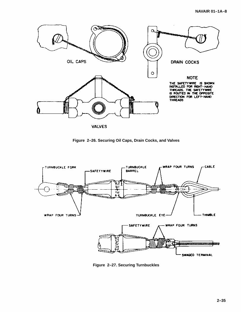
NAVAIR 01–1A–8
2–35
Figure 2–26. Securing Oil Caps, Drain Cocks, and Valves
Figure 2–27. Securing Turnbuckles

NAVAIR 01–1A–8
2–36
NOTE
Refer to Tables 2–9 through 2–11 for infor-mation regarding safety wire size andtype, number of turns, and maximumthread extension for various cable diame-ters.
2–46. SAFETY WIRING GUIDELINES AND PRE-CAUTIONS. Observe the following rules andprecautions when safety wiring aircraft components:
a. Drilled head bolts do not require safety wiringwhen installed with self–locking nuts or lockwashers perSections VII and VIII, respectively.
b. Ensure safety wire is tight when installed to pre-vent failure due to rubbing or vibration.
c. Install safety wire in such a manner that the wiretends to tighten and keep a part locked in place.
d. Overstressed safety wire may fracture whensubjected to vibrations. Safety wire shall be taut whenbeing twisted, but shall have a minimum of tension whensecured.
e. Bend wire ends into the part to avoid sharp pro-trusions which may present a safety hazard.
f. Internal wiring shall not cross over or obstruct aflow passage when an alternate method is available.
g. Closely grouped parts may be wired together.The number of parts which may be wired together de-pends on the application: three widely spaced bolts maybe wired together by the double twist method. When se-curing closely spaced bolts, the maximum numberwhich may be wired together is that which a 24–inchlength of wire is capable of securing. Widely spaced,multiple groups shall not be secured together when thefasteners are 4 to 6 inches apart. Safety wiring shall notbe used to secure fasteners or fittings spaced more than6 inches apart, unless tie points are provided on adja-cent parts to reduce the span of the safety wire.
h. When properly installed, safety wire shouldhave approximately 8–10 twists per inch.
Table 2–9. Safetywire, Type and Size for Various Turnbuckle Cable Diameters
Table 2–10. Safetywire, Number of Turns for Various Turnbuckle Cable Diameters
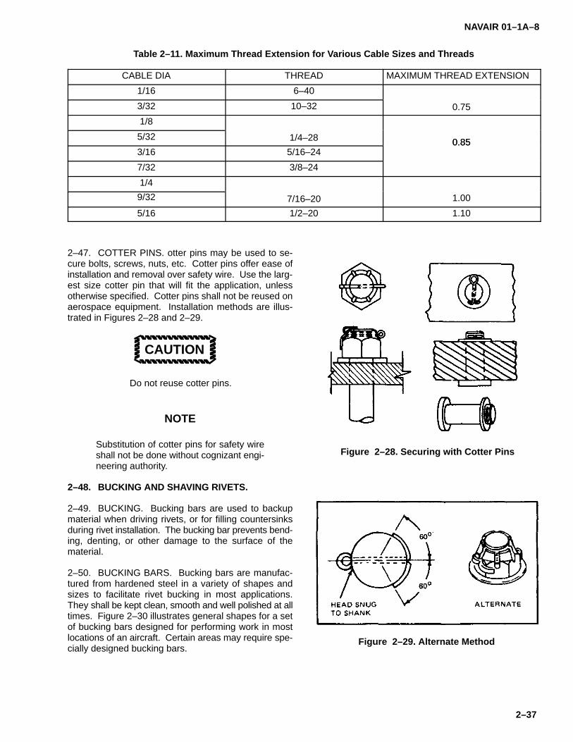
NAVAIR 01–1A–8
2–37
Table 2–11. Maximum Thread Extension for Various Cable Sizes and Threads
CABLE DIA THREAD MAXIMUM THREAD EXTENSION
1/16 6–40
3/32 10–32 0.75
1/8
5/32 1/4–28 0.853/16 5/16–24
0.85
7/32 3/8–24
1/4
9/32 7/16–20 1.00
5/16 1/2–20 1.10
2–47. COTTER PINS. otter pins may be used to se-cure bolts, screws, nuts, etc. Cotter pins offer ease ofinstallation and removal over safety wire. Use the larg-est size cotter pin that will fit the application, unlessotherwise specified. Cotter pins shall not be reused onaerospace equipment. Installation methods are illus-trated in Figures 2–28 and 2–29.
CAUTION
Do not reuse cotter pins.
NOTE
Substitution of cotter pins for safety wireshall not be done without cognizant engi-neering authority.
2–48. BUCKING AND SHAVING RIVETS.
2–49. BUCKING. Bucking bars are used to backupmaterial when driving rivets, or for filling countersinksduring rivet installation. The bucking bar prevents bend-ing, denting, or other damage to the surface of thematerial.
2–50. BUCKING BARS. Bucking bars are manufac-tured from hardened steel in a variety of shapes andsizes to facilitate rivet bucking in most applications.They shall be kept clean, smooth and well polished at alltimes. Figure 2–30 illustrates general shapes for a setof bucking bars designed for performing work in mostlocations of an aircraft. Certain areas may require spe-cially designed bucking bars.
Figure 2–28. Securing with Cotter Pins
Figure 2–29. Alternate Method

NAVAIR 01–1A–8
2–38
Figure 2–30. Types of Bucking Bars
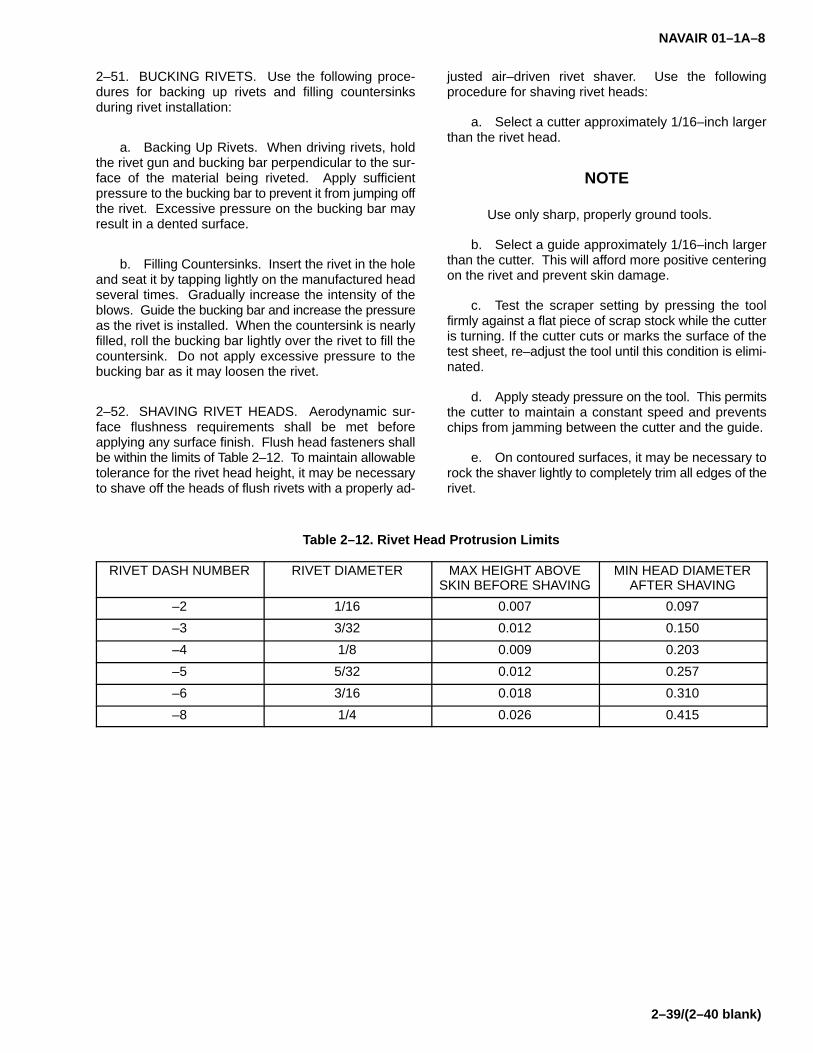
NAVAIR 01–1A–8
2–39/(2–40 blank)
2–51. BUCKING RIVETS. Use the following proce-dures for backing up rivets and filling countersinksduring rivet installation:
a. Backing Up Rivets. When driving rivets, holdthe rivet gun and bucking bar perpendicular to the sur-face of the material being riveted. Apply sufficientpressure to the bucking bar to prevent it from jumping offthe rivet. Excessive pressure on the bucking bar mayresult in a dented surface.
b. Filling Countersinks. Insert the rivet in the holeand seat it by tapping lightly on the manufactured headseveral times. Gradually increase the intensity of theblows. Guide the bucking bar and increase the pressureas the rivet is installed. When the countersink is nearlyfilled, roll the bucking bar lightly over the rivet to fill thecountersink. Do not apply excessive pressure to thebucking bar as it may loosen the rivet.
2–52. SHAVING RIVET HEADS. Aerodynamic sur-face flushness requirements shall be met beforeapplying any surface finish. Flush head fasteners shallbe within the limits of Table 2–12. To maintain allowabletolerance for the rivet head height, it may be necessaryto shave off the heads of flush rivets with a properly ad-
justed air–driven rivet shaver. Use the followingprocedure for shaving rivet heads:
a. Select a cutter approximately 1/16–inch largerthan the rivet head.
NOTE
Use only sharp, properly ground tools.
b. Select a guide approximately 1/16–inch largerthan the cutter. This will afford more positive centeringon the rivet and prevent skin damage.
c. Test the scraper setting by pressing the toolfirmly against a flat piece of scrap stock while the cutteris turning. If the cutter cuts or marks the surface of thetest sheet, re–adjust the tool until this condition is elimi-nated.
d. Apply steady pressure on the tool. This permitsthe cutter to maintain a constant speed and preventschips from jamming between the cutter and the guide.
e. On contoured surfaces, it may be necessary torock the shaver lightly to completely trim all edges of therivet.
Table 2–12. Rivet Head Protrusion Limits
RIVET DASH NUMBER RIVET DIAMETER MAX HEIGHT ABOVESKIN BEFORE SHAVING
MIN HEAD DIAMETERAFTER SHAVING
–2 1/16 0.007 0.097
–3 3/32 0.012 0.150
–4 1/8 0.009 0.203
–5 5/32 0.012 0.257
–6 3/16 0.018 0.310
–8 1/4 0.026 0.415


NAVAIR 01–1A–8
3–1
SECTION III
RIVETS
3–1. RIVETS.
3–2. Rivets include all types of fasteners in which theinstallation thereof imparts a permanent deformationwhich would force the destruction of the fastener duringremoval. Conventional non–blind fastening systemsused in aircraft structural and non–structural applica-tions include: solid, tubular, and pin (Hi–Shear) rivets,swage locked fasteners, Lockbolts, Hi–Loks, Hi–Tiguesand Huckrimp fasteners. Blind fastening systems in-clude: self–plugging mechanically locked and frictionlocked rivets, Cherrylock, Cherrymax, and Olympic–Lokrivets, Composi–Loks, Visu–Loks (Jo–Bolts), and riv-nuts. Solid rivets are used to join aircraft structures. Theother fastening systems are used in applications wherefastener strength, ease of installation, and/or tempera-ture properties of the fastener require consideration.Blind rivets are designed for applications where onlyone side of the work is accessible.
3–3. RIVET PART NUMBERS. Rivets are numberedby the Military Standard (MS), National AerospaceStandard (NAS), Air Force–Navy (AN) system, or insome cases, manufacturer’s part numbers are used.Rivet part numbers represent material, grip length, anddiameter. For example, MS20470AD2–12 is the partnumber for a universal head rivet: MS20470 is the basicnumber, AD2 indicates 2017–T4 alloy, 1/16–inch in di-ameter, and –12 indicates 3/4–inch length. The partnumber of an identical rivet made of 7050–T73 alloy isMS20470E2–12.
3–4. RIVET IDENTIFICATION. Identify rivets perMIL–HDBK–131.
3–5. RIVET MATERIALS. Rivet material dependsupon substrate, corrosion resistance, strength limita-tions, and magnetic properties. Use 1100–F aluminumrivets to join non–structural parts made of 1100–F, 3003or 5052 aluminum alloys, fiberglass/epoxy, or kevlar/epoxy. 2117–T4 aluminum alloy rivets are used to joinaluminum alloy structures. 2017–T4 or 7050–T73 alu-minum alloy rivets are used to join aluminum alloy andcomposite structures where greater strength is re-quired. 5056–H32 aluminum alloy rivets are used to joinmagnesium alloy structures due to favorable corrosion–resistance properties. Except in emergencies, rivetsmade from other materials shall not be used to join mag-nesium structures. Mild steel rivets are used primarilyto join steel structures. Galvanized rivets shall not beused to join steel parts subject to high temperatures.Corrosion–resistant steel (CRES) rivets are used pri-marily to join CRES structures. Monel rivets, used to join
nickel alloys and high nickel–steel alloys, are inter-changeable with CRES rivets. However, it isrecommended that CRES rivets be used in CRES struc-tures. Titanium rivets are used to join advancedcomposite materials where strength, weight, and holetolerance requirements are critical. Titanium rivets arehighly resistant to heat and corrosion. Copper rivets,used for joining copper alloys, leather, and other non–metallic materials, have limited usage on aircraft.
NOTEIn applications requiring non–magneticfasteners, Austenitic CRES (300 seriesstainless steel), aluminum alloy, magne-sium alloy, titanium alloy, copper, brass,bronze, and several monel alloy fastenersmay be used.
3–6. RIVET CORROSION RESISTANCE. Corrosionresistance is adequate when the rivet is made of thesame, or nearly the same material as that of the struc-ture being joined. Anodized 2117–T4, 2017–T4, and7050–T73 aluminum alloy rivets may be used in alumi-num alloy structures or non–graphite/carbonfiber–reinforced composite structures without inducingcorrosion.
CAUTION
Corrosion will result if steel, CRES, mo-nel, titanium, or copper rivets are used inaluminum structures. Such applicationsshall be confined to emergencies. In suchcases, apply one coat of zinc–chromateprimer to the rivet before and after instal-lation. Replacement shall be made assoon as proper materials are available.Uncoated aluminum rivets shall not beused on graphite or carbon–reinforcedcomposite structures or accelerated cor-rosion will occur.
3–7. RIVET PATTERN LAYOUT. Refer to the appli-cable TMS for specific repair procedures. The followinggeneral guidelines apply in most cases. With the excep-tion of damaged holes requiring oversize rivets, rivetpatterns shall have the same configuration as the origi-nal installation.
a. Rivet Spacing for Aluminum Structures.

NAVAIR 01–1A–8
3–2
1. The distance between two rivets in thesame row shall be not less than 4 times the shank diam-eter, nor greater than 10 times the shank diameter.
2. The distance between two rows of rivetsshall be not less than 2–1/2 times the shank diameter,nor greater than the largest spacing between any tworivets in the two rows.
b. Edge Distance for Aluminum Structures. (SeeFigure 3–1). Edge distance shall be not less than 2times the shank diameter, nor greater than 4 times theshank diameter.
c. Rivet Spacing for Composites.
1. The distance between two rivets in thesame row shall be not less than 4 times the shank diam-eter, nor greater than 6 times the shank diameter.
2. The distance between two rows of rivetsshall be not less than 2–1/2 times the shank diameter,nor greater than the largest spacing between any tworivets in the two rows.
d. Edge Distance for Composites. (See Figure3–2).
1. Edge distance in the major load directionshall be not less than 3 times the shank diameter.
2. Edge distance in the side edge directionshall be not less than 2–1/2 times the shank diameter.
NOTE
Refer to Table 3–1 for the maximum sheetsurface angle when installing rivets.Spotfacing is required for larger angles(see Figure 3–3). Use a soft pencil whenlaying out a rivet pattern to preventscratching the surface.
3–8. DRILLING RIVET HOLES. Refer to Section IIfor procedures on drilling metallic and composite struc-tures. Table 2–1 of Section II lists drill sizes. Tables 3–2through 3–6 list drill sizes for various types or rivets.
3–9. HOLE PREPARATION FOR RIVETS. Refer toSection II for procedures on countersinking, dimplingand subcountersinking for installing flush head fasten-ers.
3–10. RIVET FAILURE. Riveted joints are designedon the basis that total joint strength is the summation ofthe individual strengths of all rivets in the joint. Whenone rivet fails, its load is distributed among the remain-ing rivets. If the remaining rivets are unable to withstand
the redistributed load, joint failure will occur. Upon visualdetection of one failed rivet, mandatory inspection of allother rivets in the pattern is required. The following aretypes of rivet failure and recommended corrective ac-tions:
a. Rivet Shear Failure. Shear failure is caused byparallel forces exerted in opposite directions on the rivetshank. If the rivet shank is loaded beyond its yield point,permanent deformation occurs and the shank isnotched and shank separation may occur. Failed rivetsallow displacement of the mating assemblies which mayresult in joint failure.
Figure 3–1. Rivet Edge Distance For Aluminum
Figure 3–2. Rivet Edge Distance ForComposites

NAVAIR 01–1A–8
3–3
Figure 3–3. Spotfacing for Rivets
Table 3–1. Sheet Surfacing Angle Limitationsfor Riveting
Table 3–2. Drill Sizes for Solid Rivets
RIVETDIAMETER
DRILL SIZE DRILLDIAMETER
1/16 51 .0670
3/32 41 .0960
1/8 30 .1285
5/32 21 .1590
3/16 11 .1910
1/4 F .2570
5/16 P .3230
3/8 W .3860
Table 3–3. Drill Sizes for Pin (Hi–shear) Rivets
RIVETDIAMETER
DRILL SIZE DRILLDIAMETER
3/16 16 .177
7/32 5 .205
1/4 B .238
9/32 1 .272
5/16 N .302
11/32 Q .332
3/8 U .368
13/32 X .397
7/16 27/64 .4219
15/32 29/64 .4531
1/2 31/64 .4844
17/32 33/64 .5156
Table 3–4. Drill Sizes for Self–plugging Rivets(Mechanical Lock)
RIVETDIAMETER
PILOTDRILL
FINISHDRILL
HOLESIZE
1/8 32 (.116) 30 (.1285) .129 to.132
5/32 26 (.147) 20 (.161) .1595 to.1635
3/16 16 (.177) 10 (.1935) .1915 to.196
Table 3–5. Drill Sizes and Hole Size Limits forSelf–Plugging Rivets (Friction Lock)
RIVETDIAMETER
FINISHDRILL SIZE
INSPECTION LIMITSMIN MAX
3/32 40 .097 .101
1/8 30 .128 .132
5/32 20 .160 .164
3/16 10 .192 .196
7/32 2 .220 .225
1/4 F .256 .261
9/32 L .289 .295
1/8oversize
29 .137 .141
5/32oversize
16 .177 .181
3/16oversize
5 .206 .210
9/32Monel
M .294 .300
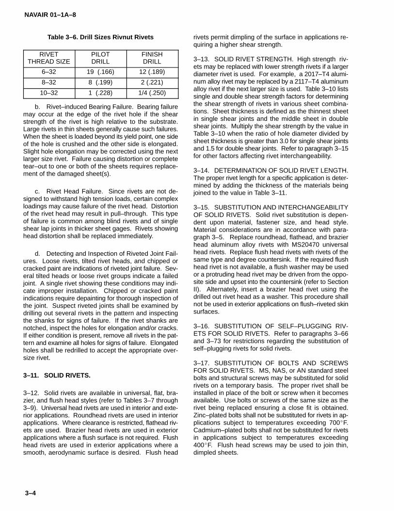
NAVAIR 01–1A–8
3–4
Table 3–6. Drill Sizes Rivnut Rivets
RIVETTHREAD SIZE
PILOTDRILL
FINISHDRILL
6–32 19 (.166) 12 (.189)
8–32 8 (.199) 2 (.221)
10–32 1 (.228) 1/4 (.250)
b. Rivet–induced Bearing Failure. Bearing failuremay occur at the edge of the rivet hole if the shearstrength of the rivet is high relative to the substrate.Large rivets in thin sheets generally cause such failures.When the sheet is loaded beyond its yield point, one sideof the hole is crushed and the other side is elongated.Slight hole elongation may be corrected using the nextlarger size rivet. Failure causing distortion or completetear–out to one or both of the sheets requires replace-ment of the damaged sheet(s).
c. Rivet Head Failure. Since rivets are not de-signed to withstand high tension loads, certain complexloadings may cause failure of the rivet head. Distortionof the rivet head may result in pull–through. This typeof failure is common among blind rivets and of singleshear lap joints in thicker sheet gages. Rivets showinghead distortion shall be replaced immediately.
d. Detecting and Inspection of Riveted Joint Fail-ures. Loose rivets, tilted rivet heads, and chipped orcracked paint are indications of riveted joint failure. Sev-eral tilted heads or loose rivet groups indicate a failedjoint. A single rivet showing these conditions may indi-cate improper installation. Chipped or cracked paintindications require depainting for thorough inspection ofthe joint. Suspect riveted joints shall be examined bydrilling out several rivets in the pattern and inspectingthe shanks for signs of failure. If the rivet shanks arenotched, inspect the holes for elongation and/or cracks.If either condition is present, remove all rivets in the pat-tern and examine all holes for signs of failure. Elongatedholes shall be redrilled to accept the appropriate over-size rivet.
3–11. SOLID RIVETS.
3–12. Solid rivets are available in universal, flat, bra-zier, and flush head styles (refer to Tables 3–7 through3–9). Universal head rivets are used in interior and exte-rior applications. Roundhead rivets are used in interiorapplications. Where clearance is restricted, flathead riv-ets are used. Brazier head rivets are used in exteriorapplications where a flush surface is not required. Flushhead rivets are used in exterior applications where asmooth, aerodynamic surface is desired. Flush head
rivets permit dimpling of the surface in applications re-quiring a higher shear strength.
3–13. SOLID RIVET STRENGTH. High strength riv-ets may be replaced with lower strength rivets if a largerdiameter rivet is used. For example, a 2017–T4 alumi-num alloy rivet may be replaced by a 2117–T4 aluminumalloy rivet if the next larger size is used. Table 3–10 listssingle and double shear strength factors for determiningthe shear strength of rivets in various sheet combina-tions. Sheet thickness is defined as the thinnest sheetin single shear joints and the middle sheet in doubleshear joints. Multiply the shear strength by the value inTable 3–10 when the ratio of hole diameter divided bysheet thickness is greater than 3.0 for single shear jointsand 1.5 for double shear joints. Refer to paragraph 3–15for other factors affecting rivet interchangeability.
3–14. DETERMINATION OF SOLID RIVET LENGTH.The proper rivet length for a specific application is deter-mined by adding the thickness of the materials beingjoined to the value in Table 3–11.
3–15. SUBSTITUTION AND INTERCHANGEABILITYOF SOLID RIVETS. Solid rivet substitution is depen-dent upon material, fastener size, and head style.Material considerations are in accordance with para-graph 3–5. Replace roundhead, flathead, and brazierhead aluminum alloy rivets with MS20470 universalhead rivets. Replace flush head rivets with rivets of thesame type and degree countersink. If the required flushhead rivet is not available, a flush washer may be usedor a protruding head rivet may be driven from the oppo-site side and upset into the countersink (refer to SectionII). Alternately, insert a brazier head rivet using thedrilled out rivet head as a washer. This procedure shallnot be used in exterior applications on flush–riveted skinsurfaces.
3–16. SUBSTITUTION OF SELF–PLUGGING RIV-ETS FOR SOLID RIVETS. Refer to paragraphs 3–66and 3–73 for restrictions regarding the substitution ofself–plugging rivets for solid rivets.
3–17. SUBSTITUTION OF BOLTS AND SCREWSFOR SOLID RIVETS. MS, NAS, or AN standard steelbolts and structural screws may be substituted for solidrivets on a temporary basis. The proper rivet shall beinstalled in place of the bolt or screw when it becomesavailable. Use bolts or screws of the same size as therivet being replaced ensuring a close fit is obtained.Zinc–plated bolts shall not be substituted for rivets in ap-plications subject to temperatures exceeding 700�F.Cadmium–plated bolts shall not be substituted for rivetsin applications subject to temperatures exceeding400�F. Flush head screws may be used to join thin,dimpled sheets.

NAVAIR 01–1A–8
3–5
Table 3–7. MS20613 and MS20615 Universal Head Solid Rivets
Code:First dash number indicates nominal shank diameter in 1/32–inch.
Second dash number indicates length in 1/16–inch.P after first dash number indicates cadmium–plated rivet.
C after first dash number indicates CRES rivet.
M after first dash number indicates monel rivet.
CU after first dash number indicates copper rivet.
B after first dash number indicates brass rivet.
Examples of Part Numbers:
MS20613–3C8 = universal head rivet, CRES, 3/32–inch diameter, 1/2–inch long.
MS20615–2M8 = universal head rivet, monel, 1/16–inch diameter, 1/2–inch long.
Finish:
Cadmium–plate per QQ–P–416.
Material:
Carbon Steel per Federal Standard 66.CRES per Federal Standard 66.
Monel per QQ–N–281.
Copper per QQ–W–341.
Brass per QQ–W–321.
Note:
Supercedes MS20435.

NAVAIR 01–1A–8
3–6
Table 3–8. MS20426 and MS20427 Flush Head Solid Rivets
Code:First dash number indicates nominal shank diameter in 1/32–inch.Second dash number indicates length in 1/16–inch.C after second dash number indicates cadmium–plated rivet.A after basic part number indicates 1100–F aluminum rivet.B after basic part number indicates 5056–H32 aluminum alloy rivet.AD after basic part number indicates 2117–T4 aluminum alloy rivet.D after basic part number indicates 2017–T4 aluminum alloy rivet.E after basic part number indicates 7050–T73 aluminum alloy rivet.K after basic part number indicates 2119 aluminum alloy rivet.T after basic part number indicates Titanium–Columbium Alloy 45Cb rivet.C after basic part number indicates copper rivet.F after basic part number indicates CRES rivet.M after basic part number indicates monel rivet.
Examples of Part Numbers:MS20426AD3–12 = 2117–T4 aluminum alloy rivet, 3/32–inch diameter, 3/4–inch long.MS20427M222 = monel rivet, 1/16–inch diameter, 1/8–inch long.
Finish:Cadmium–plate per QQ–P–416.
Material:Carbon Steel per Federal Standard 66.CRES per Federal Standard 66.Monel per QQ–N–281, annealed.Copper per QQ–W–341, annealed.Aluminum Alloys 1100–F, 5056–H32, 2117–T4, 7050–T73, and 2017–T4.45Cb Titanium–Columbium Alloy.

NAVAIR 01–1A–8
3–7
Table 3–9. MS20470 Universal Head Solid Rivet
Code:First dash number indicates nominal shank diameter in 1/32–inch.Second dash number indicates length in 1/16–inch.A after basic part number indicates 1100–H14 aluminum alloy rivet.AD after basic part number indicates 2117–T4 aluminum alloy rivet.B after basic part number indicates 5056–H32 aluminum alloy rivet.D after basic part number indicates 2017–T4 aluminum alloy rivet.E after basic part number indicates 7050–T73 aluminum alloy rivet.T after basic part number indicates 45Cb Titanium–Columbium Alloy rivet.
Examples of Part Numbers:MS20470AD2–12 = 2117–T4 aluminum alloy rivet, 1/16–inch diameter, 3/4–inch long.
Material:Aluminum Alloys 1100–H14, 2017–T4, 7050–T73, 2117–T4, and 5056–H32 per MIL–W–7986.45Cb Titanium–Columbium Alloy.
Supercedes AN470.

NAVAIR 01–1A–8
3–8
Table 3–10. Shear Strength of Solid Rivets (Pounds)
RAISED HEAD RIVETS
RIVET DIAMETERRIVET
MATERIAL 1/16 3/32 1/8 5/32 3/16 1/4 5/16 3/8
2117–T4 106 217 388 596 862 1555 2440 3510
2017–T4 120 247 442 675 977 1765 2785 3980
2024–T4 145 296 531 814 1175 2125 3360 4800
5056–H32 99 203 363 556 802 1450 2295 3275
SINGLE SHEAR RIVET STRENGTH FACTORS
RIVET DIAMETERSHEET
THICKNESS 1/16 3/32 1/8 5/32 3/16 1/4 5/16 3/8
.016 .964 — — — — — — —
.018 .981 .912 — — — — — —
.020 .995 .933 — — — — — —
.025 1.000 .970 .920 — — — — —
.032 — 1.000 .964 .925 — — — —
.036 — — .981 .946 .912 — — —
.040 — — .995 .964 .933 — — —
.045 — — 1.000 .981 .953 — — —
.050 — — — .995 .970 .920 — —
.063 — — — 1.000 1.000 .961 .922 —
.071 — — — — — .979 .944 .909
.080 — — — — — .995 .964 .933
.090 — — — — — 1.000 .981 .953
.100 — — — — — — .995 .972
.125 — — — — — — 1.000 1.000
DOUBLE SHEAR RIVET STRENGTH FACTORS
RIVET DIAMETERSHEET
THICKNESS 1/16 3/32 1/8 5/32 3/16 1/4 5/16 3/8
.016 .687 — — — — — — —
.018 .744 .518 — — — — — —
.020 .789 .585 — — — — — —
.025 .870 .708 .545 — — — — —
.032 .941 .814 .687 .560 — — — —
.036 .969 .857 .744 .630 .518 — — —
.040 .992 .891 .789 .687 .585 — — —
.045 1.000 .924 .834 .744 .653 — — —
.050 — .951 .870 .789 .708 .545 — —
.063 — 1.000 .937 .872 .808 .679 .550 —
.071 — — .966 .909 .852 .737 .622 .508
.080 — — .992 .941 .891 .789 .687 .585
.090 — — 1.000 .969 .924 .834 .744 .653
.100 — — — .992 .951 .870 .789 .708
.125 — — — 1.000 1.000 .935 .870 .805
.160 — — — — — .992 .941 .891
.190 — — — — — 1.000 .981 .939
.250 — — — — — — 1.000 1.000

NAVAIR 01–1A–8
3–9
Table 3–11. Calculating Correct Rivet Length
RIVET DIAMETER MATERIAL THICKNESS ADD
1/4 or less 1/2 inch or less 1–1/2 X diameter of rivet
Over 1/2 inch 1–1/2 X diameter of rivet + 1/16 inchfor every 1/2 inch of material thick-ness
5/16 or more 1 inch or less 1–1/2 X diameter of rivet
Over 1 inch 1–1/2 X diameter of rivet + 1/16 inchfor every 1 inch of material thickness
CAUTION
Screw type fasteners shall not be used inengine intake ducts.
3–18. SOLID RIVET TOOLING. The following toolsmay be required for the installation of solid rivets:
a. Bucking Bars. Refer to Section II for informationon bucking bars.
b. Rivet Sets. A rivet set is a tool with a die in oneend used for driving a particular type or rivet. Rivet setsare made of hardened steel and must be kept well pol-ished at all times.
c. Rivet Draw Sets. A rivet draw set is essentiallya rod with a 1/32–inch oversize hole drilled in one end(see Figure 3–4). The draw set expands the rivet shankas the sheets are drawn together.
3–19. INSTALLATION OF SOLID RIVETS. Preparethe sheets to be joined in accordance with the proce-dures of Section II. Secure the sheets in position withtemporary skin fasteners (see Figure 3–5). Use carewhen riveting thin gage materials to avoid damaging thesurface. Aircraft power riveting is done by upsetting theshank against a bucking bar (refer to Section II). Drivesolid rivets using a hand gun, rivet squeezer, or pneu-matic rivet gun as follows:
a. Hand Gun. Hand tools shall be used only whenpower tools are unavailable. Solid rivets may be drivenfrom the head end and bucked on the shank end, or driv-en from the shank end and bucked on the head with arivet set.
b. Rivet Squeezer. Rivet squeezers are availablein hand and pneumatic styles (see Figure 3–6). One jawof the squeezer is stationary and effectively serves as abucking bar, while the movable jaw upsets the shank.Rivet squeezers may be used only near sheet edges.
c. Pneumatic Rivet Gun. Pneumatic rivet guns(see Figure 3–7) are used in conjunction with a buckingbar and rivet set. Apply pressure to the rivet head andupset the shank against the bucking bar. Excessivepressure may damage the surface.
3–20. SOLID RIVET INSPECTION. Inspect installedsolid rivets as follows:
a. The height of the manufactured head shall be0.3 to 0.5 times the shank diameter.
b. The diameter of the manufactured head shallbe 1.4 to 1.5 times the shank diameter.
c. Figure 3–8 shows correctly and incorrectly driv-en rivets and Table 3–12 provides the cause andcorrective action for incorrectly driven rivets.
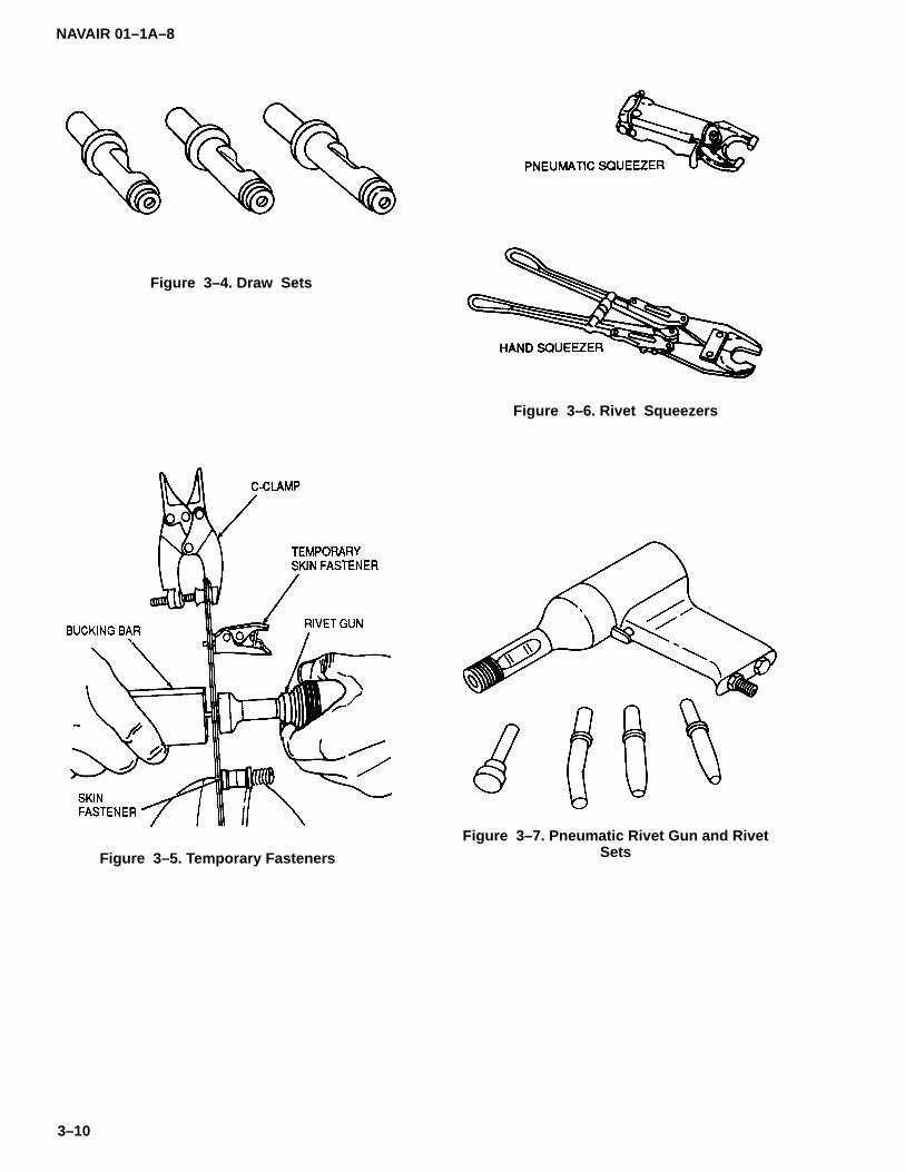
NAVAIR 01–1A–8
3–10
Figure 3–4. Draw Sets
Figure 3–5. Temporary Fasteners
Figure 3–6. Rivet Squeezers
Figure 3–7. Pneumatic Rivet Gun and RivetSets

NAVAIR 01–1A–8
3–11
Figure 3–8. Correctly and Incorrectly Driven Rivets
Table 3–12. Incorrectly Driven Rivets
IMPERFECTION CAUSE REMEDY ACTION
A. Cut head. Improperly held tools. Hold riveting tools firmlyagainst work.
Replace rivet.
B. Excessively flat head,resultant head cracks.
Excessive driving, toomuch pressure on buck-ing bar.
Improve rivetingtechnique.
Replace rivet.
C. Sheet separation. Work not held firmly to-gether and rivet shankswelled.
Fasten work firmly togeth-er to prevent slipping.
Replace rivet.
D. Sloping head. a. Bucking bar not heldfirmly.
b. Bucking bar permittedto slide and bounce overthe rivet.
Hold bucking bar firmlywithout too much pres-sure.
Replace rivet.
E. Buckled shank Improperly rivet length,and D above.
D above and rivet ofproper length.
Replace rivet.
3–21. REMOVAL OF SOLID RIVETS. Remove solidrivets using the following procedure (see Figure 3–9):
a. File a flat surface on the manufactured head ofprotruding head rivets if the head is accessible. It is pref-erable to work on the manufactured head rather than thebucked head since the former is usually more symmetri-cal about the shank.
b. Centerpunch the flat surface and drill throughthe rivet head using a slightly undersize drill.
c. If the other end of the rivet is supported, shearoff drilled head with a chisel.

NAVAIR 01–1A–8
3–12
d. Firmly support the sheet from the opposite sideand remove the shank with a pin punch. If the rivet doesnot come out easily, drill the rivet out with an undersizedrill.
3–22. TUBULAR RIVETS.
3–23. Tubular rivets are available in oval (MS16535)and 150� flush (MS16536) head styles and aremanufactured from carbon steel, aluminum alloy, mo-nel, brass, and copper. Tubular rivets shall not be usedin aircraft structural applications.
3–24. PIN (HI–SHEAR) RIVETS.
3–25. Pin (Hi–Shear) rivets are essentially threadlessbolts locked by a swaged metal collar designed for usein shear applications (refer to Tables 3–13 through3–17). Due to the high shear strengths of pin rivets rela-tive to aluminum alloys, they are generally used only inthicker gage sheets. Pin rivets shall not be used in ap-plications where the shank diameter exceeds the griplength.
3–26. SUBSTITUTION OF BOLTS FOR PIN (HI–SHEAR) RIVETS. Pin rivets may be replaced by MS,NAS, and AN bolts of the same diameter and of equalshear strength. Tighten with a self–locking nut. Ensurethe bolt thread does not extend into the sheets being fas-tened.
3–27. DETERMINING PIN (HI–SHEAR) RIVETLENGTH. The straight portion of the shank should notextend more than 1/16–inch through the substrate. Awasher may be used under the collar or the head to ob-tain the correct protrusion.
3–28. SPOTFACING FOR PIN (HI–SHEAR) RIVETS.Spotfacing shall be used under the rivet head when thesurface is not flat. Spotfacing shall be used under thecollar when the surface angle exceeds 5�.
3–29. PIN (HI–SHEAR) RIVET INSTALLATIONTOOLS. Pin rivet tool sets differ from solid rivet sets onlyin the design of the collar swaging, trimming, and dis-charge features (see Figure 3–10).
3–30. PRECAUTIONS WHEN USING PIN (HI–SHEAR) RIVETS. Observe the following precautionswhen installing pin rivets:
a. Ensure sheets are firmly clamped together us-ing temporary fasteners to avoid selecting a rivet ofincorrect length. The straight portion of the stud shouldnot protrude more than 1/16–inch through the hole be-fore driving.
b. Ensure a tight fit as pin rivet shanks do not ex-pand to fill oversize holes.
c. Ensure rivet holes are properly aligned. Pin riv-ets are used under high shear loads and the bearingsurface is critical.
d. Do not overdrive or underdrive pin rivets. Ten-sile strength may be decreased under such conditions.
3–31. INSTALLATION OF PIN (HI–SHEAR) RIVETS.Drive pin rivets from either the collar or head end as fol-lows:
a. Collar End. Insert rivet into hole. Place buckingbar firmly against rivet head. Slide collar over protrudingstud and rivet set over collar. Apply pressure until collaris properly formed and excess material trimmed off (seeFigure 3–11).
b. Head End. Insert rivet into hole. Slide collarover protruding stud. Place bucking bar with rivet set in-serted over the collar. Apply pressure with rivet gun untilcollar is formed and excess material trimmed off (seeFigure 3–12).
NOTE
Inspect installed pin rivets in accordancewith Figure 3–13.
3–32. REMOVAL OF PIN (HI–SHEAR) RIVETS. Pinrivets shall be removed in accordance with Figure 3–14.
3–33. SWAGE LOCKED FASTENERS.
3–34. Swage locked fasteners consist of a pin and aswagged collar. They are available in pull–type andstump–type designs (refer to Tables 3–18 through3–23).
3–35. INSTALLATION OF SWAGE LOCKED FAS-TENERS. The following procedure shall be used wheninstalling swage locked fasteners:
a. Pull–type Fasteners. Install pull–type fastenersin accordance with Figure 3–15. Table 3–24 lists instal-lation tools for pull–type fasteners.
b. Stump–Type Fasteners. Stump–type fastenersare installed with a conventional rivet hammer and aspecial swaging set for the collar (see Figure 3–15).Table 3–25 lists stump–type fasteners swaging tools.Stump–type fasteners require bucking during installa-tion.
3–36. COLLAR INSPECTION. Inspect swaged collarsvisually or with the inspection gages shown in Table3–26.
3–37. REMOVAL OF SWAGE LOCKED FASTEN-ERS. Remove swage locked fasteners by theprocedure shown at the bottom of Figure 3–15.

NAVAIR 01–1A–8
3–13
Figure 3–9. Removal of Solid Rivets
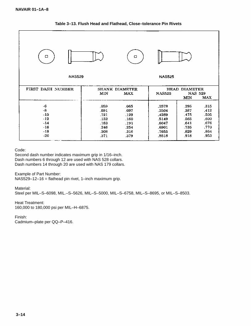
NAVAIR 01–1A–8
3–14
Table 3–13. Flush Head and Flathead, Close–tolerance Pin Rivets
Code:Second dash number indicates maximum grip in 1/16–inch.Dash numbers 6 through 12 are used with NAS 528 collars.Dash numbers 14 through 20 are used with NAS 179 collars.
Example of Part Number:NAS529–12–16 = flathead pin rivet, 1–inch maximum grip.
Material:Steel per MIL–S–6098, MIL.–S–5626, MIL–S–5000, MIL–S–6758, MIL–S–8695, or MIL–S–8503.
Heat Treatment:160,000 to 180,000 psi per MIL–H–6875.
Finish:Cadmium–plate per QQ–P–416.

NAVAIR 01–1A–8
3–15
Table 3–14. Protruding and Flush Head Pin Rivets
Code:Second dash number indicates maximum grip in 1/16–inch.NAS1054 and NAS1055 pin rivets are used with NAS179 or NAS528 collars.
Example of Part Number:NAS1054–6–8 = protruding head pin rivet, 1/2–inch maximum grip.
Material:Steel per MIL–S–6098, MIL–S–5626, MIL–S–5000, MIL–S–6758, MIL–S–8695, or MIL–S–8503.
Heat Treatment:160,000 to 180,000 psi per MIL–H–6875.
Finish:Cadmium–plate per QQ–P–416.
Supercedes NAS177 and NAS178.

NAVAIR 01–1A–8
3–16
Table 3–15. Titanium Alloy Pin Rivets
Code:Last two digits of basic part number indicate nominal diameter in 1/32–inch.Dash number indicates maximum grip in 1/16–inch.V after basic part number indicates 6Al–4V titanium alloy rivet.NAS1806–NAS1812 and NAS1906–NAS1912 rivets are used with NAS528 collars.NAS1814, NAS1816, NAS1914, and NAS1916 rivets are used with NAS179 collars.
Examples of Part Numbers:NAS1808–12 = flathead pin rivet, 4Al–4Mn titanium alloy, 1/4–inch diameter, 3/4–inch maximum grip.NAS1908V12 = flush head pin rivet, 6Al–4V titanium alloy, 1/4–inch diameter, 3/4–inch maximum grip.
Material:4Al–4Mn titanium alloy per NAS621.6Al–4V titanium alloy per NAS621.
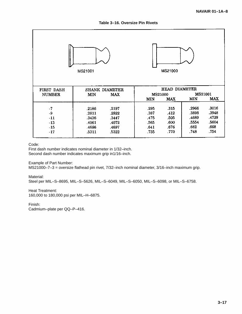
NAVAIR 01–1A–8
3–17
Table 3–16. Oversize Pin Rivets
Code:First dash number indicates nominal diameter in 1/32–inch.Second dash number indicates maximum grip in1/16–inch.
Example of Part Number:MS21000–7–3 = oversize flathead pin rivet, 7/32–inch nominal diameter, 3/16–inch maximum grip.
Material:Steel per MIL–S–8695, MIL–S–5626, MIL–S–6049, MIL–S–6050, MIL–S–6098, or MIL–S–6758.
Heat Treatment:160,000 to 180,000 psi per MIL–H–6875.
Finish:Cadmium–plate per QQ–P–416.
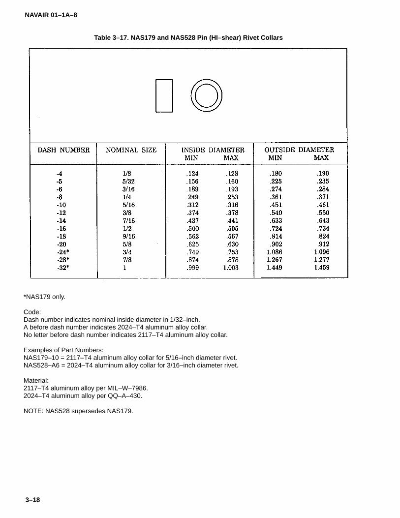
NAVAIR 01–1A–8
3–18
Table 3–17. NAS179 and NAS528 Pin (HI–shear) Rivet Collars
*NAS179 only.
Code:Dash number indicates nominal inside diameter in 1/32–inch.A before dash number indicates 2024–T4 aluminum alloy collar.No letter before dash number indicates 2117–T4 aluminum alloy collar.
Examples of Part Numbers:NAS179–10 = 2117–T4 aluminum alloy collar for 5/16–inch diameter rivet.NAS528–A6 = 2024–T4 aluminum alloy collar for 3/16–inch diameter rivet.
Material:2117–T4 aluminum alloy per MIL–W–7986.2024–T4 aluminum alloy per QQ–A–430.
NOTE: NAS528 supersedes NAS179.
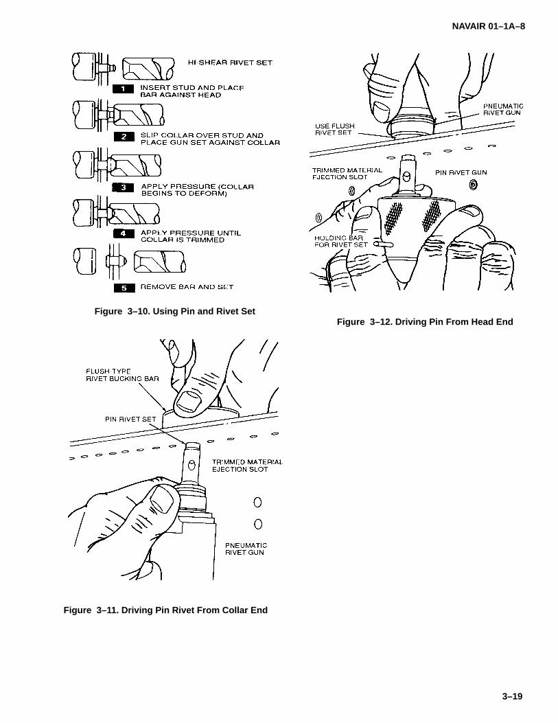
NAVAIR 01–1A–8
3–19
Figure 3–10. Using Pin and Rivet Set
Figure 3–11. Driving Pin Rivet From Collar End
Figure 3–12. Driving Pin From Head End

NAVAIR 01–1A–8
3–20
Figure 3–13. Pin Rivet Inspection
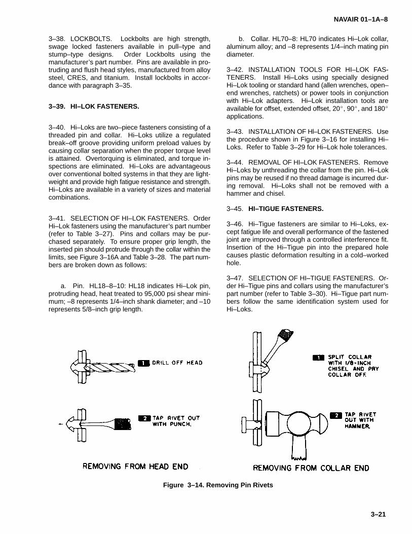
NAVAIR 01–1A–8
3–21
3–38. LOCKBOLTS. Lockbolts are high strength,swage locked fasteners available in pull–type andstump–type designs. Order Lockbolts using themanufacturer’s part number. Pins are available in pro-truding and flush head styles, manufactured from alloysteel, CRES, and titanium. Install lockbolts in accor-dance with paragraph 3–35.
3–39. HI–LOK FASTENERS.
3–40. Hi–Loks are two–piece fasteners consisting of athreaded pin and collar. Hi–Loks utilize a regulatedbreak–off groove providing uniform preload values bycausing collar separation when the proper torque levelis attained. Overtorquing is eliminated, and torque in-spections are eliminated. Hi–Loks are advantageousover conventional bolted systems in that they are light-weight and provide high fatigue resistance and strength.Hi–Loks are available in a variety of sizes and materialcombinations.
3–41. SELECTION OF HI–LOK FASTENERS. OrderHi–Lok fasteners using the manufacturer’s part number(refer to Table 3–27). Pins and collars may be pur-chased separately. To ensure proper grip length, theinserted pin should protrude through the collar within thelimits, see Figure 3–16A and Table 3–28. The part num-bers are broken down as follows:
a. Pin. HL18–8–10: HL18 indicates Hi–Lok pin,protruding head, heat treated to 95,000 psi shear mini-mum; –8 represents 1/4–inch shank diameter; and –10represents 5/8–inch grip length.
b. Collar. HL70–8: HL70 indicates Hi–Lok collar,aluminum alloy; and –8 represents 1/4–inch mating pindiameter.
3–42. INSTALLATION TOOLS FOR HI–LOK FAS-TENERS. Install Hi–Loks using specially designedHi–Lok tooling or standard hand (allen wrenches, open–end wrenches, ratchets) or power tools in conjunctionwith Hi–Lok adapters. Hi–Lok installation tools areavailable for offset, extended offset, 20�, 90�, and 180�applications.
3–43. INSTALLATION OF Hl–LOK FASTENERS. Usethe procedure shown in Figure 3–16 for installing Hi–Loks. Refer to Table 3–29 for Hi–Lok hole tolerances.
3–44. REMOVAL OF HI–LOK FASTENERS. RemoveHi–Loks by unthreading the collar from the pin. Hi–Lokpins may be reused if no thread damage is incurred dur-ing removal. Hi–Loks shall not be removed with ahammer and chisel.
3–45. HI–TIGUE FASTENERS.
3–46. Hi–Tigue fasteners are similar to Hi–Loks, ex-cept fatigue life and overall performance of the fastenedjoint are improved through a controlled interference fit.Insertion of the Hi–Tigue pin into the prepared holecauses plastic deformation resulting in a cold–workedhole.
3–47. SELECTION OF HI–TIGUE FASTENERS. Or-der Hi–Tigue pins and collars using the manufacturer’spart number (refer to Table 3–30). Hi–Tigue part num-bers follow the same identification system used forHi–Loks.
Figure 3–14. Removing Pin Rivets
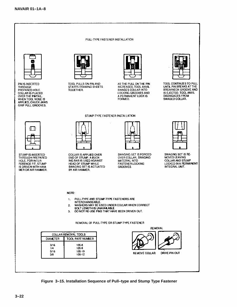
NAVAIR 01–1A–8
3–22
Figure 3–15. Installation Sequence of Pull–type and Stump Type Fastener

NAVAIR 01–1A–8
3–23
Table 3–18. Swage Locking, Shear Head, Close–Tolerance Rivets
NAS1414 and NAS1424 use NAS1080C4 collars.NAS1415 and NAS1425 use NAS1080C5 collars.NAS1436, NAS1446, NAS1416, and NAS1426 use NAS1080C6 collars.NAS1438, NAS1448, NAS1418, and NA81428 use NAS1080C8 collars.NAS1440, NAS1450, NAS1420, and NAS1430 use NAS1080C10 collars.NAS1442, NAS1452, NAS1422, and NAS1432 use NAS1080C12 collars.
Example of Part Number:NAS1438–9 = flush head pin rivet, shear head, 1/4–inch nominal diameter, 9/16–inch grip.
Material:Alloy Steel per NAS1413.

NAVAIR 01–1A–8
3–24
Table 3–19. Swage Locking, Tension Head, Close–Tolerance Alloy Steel Rivets
NAS1465 and NAS1475 use NAS1080–5 collars.NAS1486, NAS1496, NAS1456, NAS1466, and NAS1476 use NAS1080–6 collars.NAS1488, NAS1498, NAS1458, NAS1468, and NAS1478 use NAS1080–8 collars.NAS1490, NAS1500, NAS1460, NAS1470, and NAS1480 use NAS1080P10 collars.NAS1492, NAS1502, NAS1462, NAS1472, and NAS1482 use NAS1080P12 collars.
Example of Part Number:NAS1488–9 = flush head pin rivet, tension head, 1/4–inch nominal diameter, 9/16–inch grip.
Material:Alloy Steel per NAS1413.
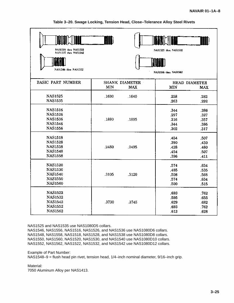
NAVAIR 01–1A–8
3–25
Table 3–20. Swage Locking, Tension Head, Close–Tolerance Alloy Steel Rivets
NAS1525 and NAS1535 use NAS1080D5 collars.NAS1546, NAS1556, NAS1516, NAS1526, and NAS1536 use NAS1080D6 collars.NAS1548, NAS1558, NAS1518, NAS1528, and NAS1538 use NAS1080D8 collars.NAS1550, NAS1560, NAS1520, NAS1530, and NAS1540 use NAS1080D10 collars.NAS1552, NAS1562, NAS1522, NAS1532, and NAS1542 use NAS1080D12 collars.
Example of Part Number:NAS1548–9 = flush head pin rivet, tension head, 1/4–inch nominal diameter, 9/16–inch grip.
Material:7050 Aluminum Alloy per NAS1413.

NAVAIR 01–1A–8
3–26
Table 3–21. Swage Locking, Tension Head, Titanium Alloy Rivets
NAS2005 and NAS2105 use NAS1080–5 collars.NAS2006, NAS2106, NAS2206, and NAS2306 use NAS1080–6 collars.NAS2008, NAS2108, NAS2208, and NAS2308 use NAS1080–8 collars.NAS2010, NAS2110, NAS2210, and NAS2310 use NAS1080–10 collars.NAS2012 and NAS2112 use NAS1080–12 collars.
Code:Last two digits of basic part number indicate diameter in 1/32–inch.Dash number indicates nominal grip in 1/16–inch.V after basic dash number indicates 6Al–4V titanium alloy rivet.
Examples of Part Numbers:NAS2206–8 = protruding head, 4Al–4Mn titanium alloy rivet, 3/16–inch diameter, 1/2–inch grip.NAS2306V8 = flush head, 6Al–4V titanium alloy rivet, 3/16–inch diameter, 1/2–inch grip.
Material:4Al–4Mn titanium alloy per NAS621.6Al–4V titanium alloy per NAS621.

NAVAIR 01–1A–8
3–27
Table 3–22. Swage Locking, Shear Head, Titanium Alloy Rivets
NAS2406, NAS2506, NAS2606, and NAS2706 use NAS1080C6 collars.NAS2408, NAS2508, NAS2608, and NAS2708 use NAS1080C8 collars.NAS2410, NAS2510, NAS2610, and NAS2810 use NAS1080C10 collars.NAS2412, NAS2512, NAS2612, and NAS2712 use NAS1080C12 collars.
Code:Last two digits of basic part number indicate diameter in 1/32–inch.Dash number indicates nominal grip in 1/16–inch.V after basic dash number indicates 6Al–4V titanium alloy rivet.
Examples of Part Numbers:NAS2406–8 = protruding head, 4Al–4Mn titanium alloy rivet, 3/16–inch diameter, 1/2–inch grip.NAS2506V8 = flush head, 6Al–4V titanium alloy rivet, 3/16–inch diameter, 1/2–inch grip.
Material:4Al–4Mn titanium alloy per NAS621.6Al–4V titanium alloy per NAS621.
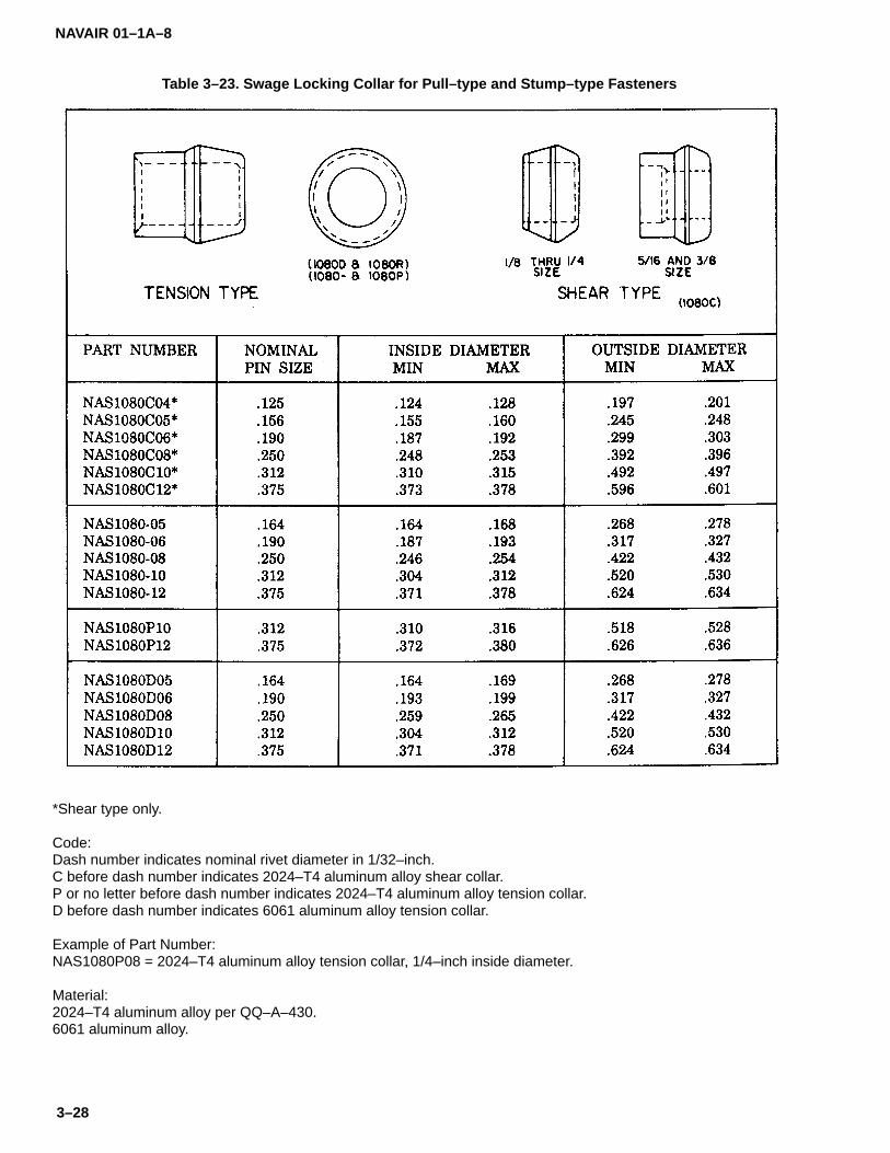
NAVAIR 01–1A–8
3–28
Table 3–23. Swage Locking Collar for Pull–type and Stump–type Fasteners
*Shear type only.
Code:Dash number indicates nominal rivet diameter in 1/32–inch.C before dash number indicates 2024–T4 aluminum alloy shear collar.P or no letter before dash number indicates 2024–T4 aluminum alloy tension collar.D before dash number indicates 6061 aluminum alloy tension collar.
Example of Part Number:NAS1080P08 = 2024–T4 aluminum alloy tension collar, 1/4–inch inside diameter.
Material:2024–T4 aluminum alloy per QQ–A–430.6061 aluminum alloy.

NAVAIR 01–1A–8
3–29
Table 3–24. Pull–type Fastener Installation Tools and Nose Assemblies

NAVAIR 01–1A–8
3–30
Table 3–25. Stump–type Fastener Collar Swage Tools
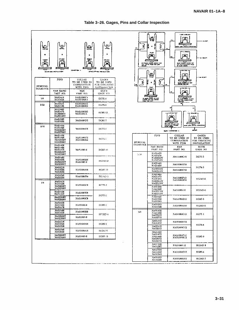
NAVAIR 01–1A–8
3–31
Table 3–26. Gages, Pins and Collar Inspection
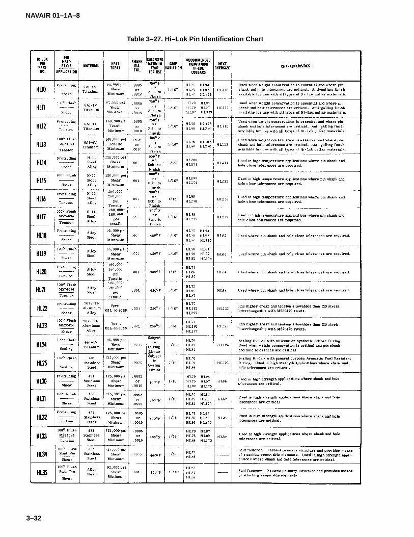
NAVAIR 01–1A–8
3–32
Table 3–27. Hi–Lok Pin Identification Chart
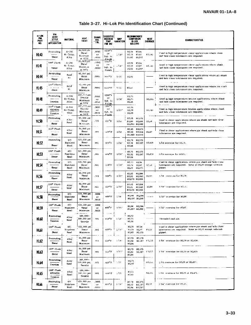
NAVAIR 01–1A–8
3–33
Table 3–27. Hi–Lok Pin Identification Chart (Continued)

NAVAIR 01–1A–8
3–34
Table 3–27. Hi–Lok Pin Identification Chart (Continued)

NAVAIR 01–1A–8
3–35
Table 3–27. Hi–Lok Pin Identification Chart (Continued)
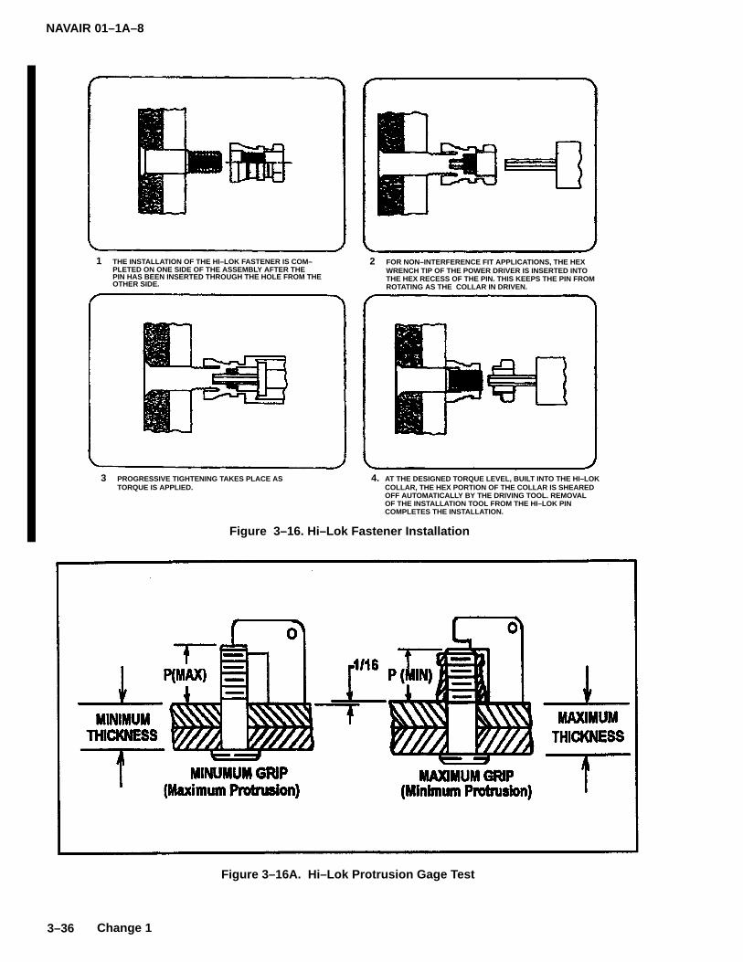
NAVAIR 01–1A–8
3–36 Change 1
1 THE INSTALLATION OF THE HI–LOK FASTENER IS COM–PLETED ON ONE SIDE OF THE ASSEMBLY AFTER THEPIN HAS BEEN INSERTED THROUGH THE HOLE FROM THEOTHER SIDE.
Figure 3–16. Hi–Lok Fastener Installation
2 FOR NON–INTERFERENCE FIT APPLICATIONS, THE HEXWRENCH TIP OF THE POWER DRIVER IS INSERTED INTOTHE HEX RECESS OF THE PIN. THIS KEEPS THE PIN FROMROTATING AS THE COLLAR IN DRIVEN.
3 PROGRESSIVE TIGHTENING TAKES PLACE ASTORQUE IS APPLIED.
4. AT THE DESIGNED TORQUE LEVEL, BUILT INTO THE HI–LOKCOLLAR, THE HEX PORTION OF THE COLLAR IS SHEAREDOFF AUTOMATICALLY BY THE DRIVING TOOL. REMOVALOF THE INSTALLATION TOOL FROM THE HI–LOK PIN COMPLETES THE INSTALLATION.
Figure 3–16A. Hi–Lok Protrusion Gage Test
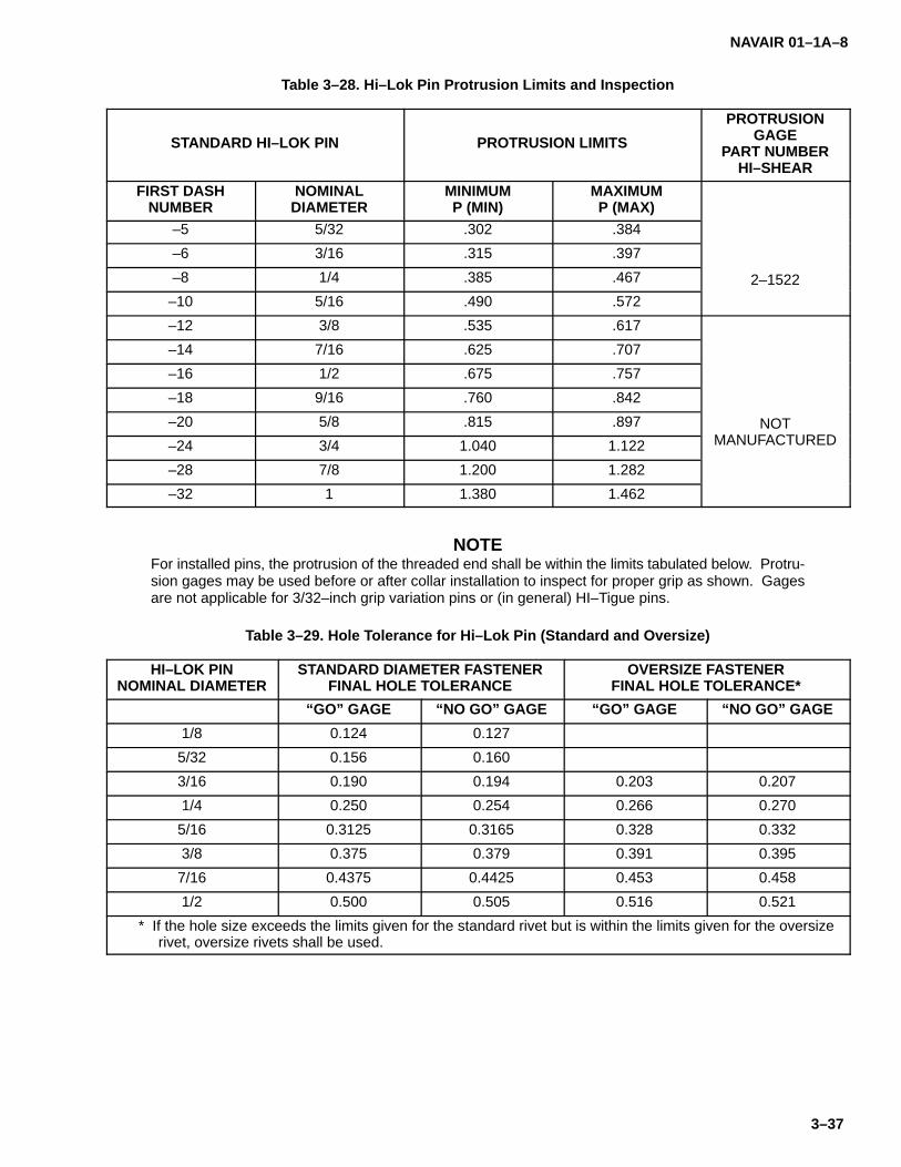
NAVAIR 01–1A–8
3–37
Table 3–28. Hi–Lok Pin Protrusion Limits and Inspection
STANDARD HI–LOK PIN PROTRUSION LIMITS
PROTRUSIONGAGE
PART NUMBERHI–SHEAR
FIRST DASHNUMBER
NOMINALDIAMETER
MINIMUMP (MIN)
MAXIMUMP (MAX)
–5 5/32 .302 .384
–6 3/16 .315 .397
–8 1/4 .385 .467 2–1522
–10 5/16 .490 .572
–12 3/8 .535 .617
–14 7/16 .625 .707
–16 1/2 .675 .757
–18 9/16 .760 .842
–20 5/8 .815 .897 NOT
–24 3/4 1.040 1.122 MANUFACTURED
–28 7/8 1.200 1.282
–32 1 1.380 1.462
NOTEFor installed pins, the protrusion of the threaded end shall be within the limits tabulated below. Protru-sion gages may be used before or after collar installation to inspect for proper grip as shown. Gagesare not applicable for 3/32–inch grip variation pins or (in general) HI–Tigue pins.
Table 3–29. Hole Tolerance for Hi–Lok Pin (Standard and Oversize)
HI–LOK PINNOMINAL DIAMETER
STANDARD DIAMETER FASTENERFINAL HOLE TOLERANCE
OVERSIZE FASTENERFINAL HOLE TOLERANCE*
“GO” GAGE “NO GO” GAGE “GO” GAGE “NO GO” GAGE
1/8 0.124 0.127
5/32 0.156 0.160
3/16 0.190 0.194 0.203 0.207
1/4 0.250 0.254 0.266 0.270
5/16 0.3125 0.3165 0.328 0.332
3/8 0.375 0.379 0.391 0.395
7/16 0.4375 0.4425 0.453 0.458
1/2 0.500 0.505 0.516 0.521
* If the hole size exceeds the limits given for the standard rivet but is within the limits given for the oversizerivet, oversize rivets shall be used.
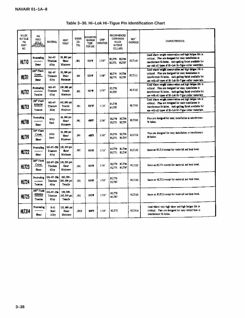
NAVAIR 01–1A–8
3–38
Table 3–30. Hi–Lok Hi–Tigue Pin Identification Chart

NAVAIR 01–1A–8
3–39
Table 3–30. Hi–Lok Hi–Tigue Pin Identification Chart (Continued)
3–48. INSTALLATION TOOLS FOR HI–TIGUE FAS-TENERS. Hi–Tigue pins may be installed using handrivet guns and bucking bars and Hi–Tigue collars maybe installed using standard tooling.
3–49. INSTALLATION OF HI–TIGUE FASTENERS.Hi–Tigues shall be installed by the procedure shown inFigure 3–17.
3–50. REMOVAL OF HI–TIGUE FASTENERS. Hi–Ti-gues shall be removed using the same procedure as forHi–Loks (refer to paragraph 3–46).
3–51. HUCKRIMP FASTENERS.
3–52. Huckrimp fasteners are two–piece threaded fas-teners consisting of a fatigue–resistant pin and acylindrical nut (refer to Tables 3–31 through 3–34).
3–53. INSTALLATION TOOLS FOR HUCKRIMP FAS-TENERS. Table 3–35 provides installation tools forHuckrimp fasteners. Tools are selected on the basis ofnut diameter and material.
3–54. INSTALLATION OF HUCKRIMP FASTENERS.Use the following procedure for installing Huckrimp fas-teners (refer to Figure 3–18):
a. Insert pin into hole and thread nut finger tight.Apply light torque to draw sheets together.

NAVAIR 01–1A–8
3–40
b. Place installation tool on nut. Actuate tool tocrimp the nut onto pin.
3–55. INSPECTION OF HUCKRIMP FASTENERS.Refer to Table 3–36 for the appropriate inspection gagesfor installed Huckrimp fasteners.
3–56. REMOVAL OF HUCKRIMP FASTENERS. Re-move Huckrimp fasteners using a collar removal tool orby splitting the nut lengthwise (see Figure 3–15).
3–57. BLIND FASTENING SYSTEMS.
3–58. The type of blind fastener used depends uponlocation, material, and strength requirements for thatparticular application. Blind fastener requirements andinstallation/removal procedures are provided below:
3–59. TYPES OF BLIND RIVETS. The following aretypes of blind rivets:
a. Standard Self–plugging. These blind rivetsconsist of a hollow sleeve and a spindle with an in-creased diameter in the plug section. The blind head isformed as the spindle is pulled into the sleeve.
b. Self–plugging, Mechanically Locked. Theseblind rivets consist of a multiple piece construction andrely on a mechanical means of locking the spindle to thesleeve.
c. Bulbed Self–plugging, Mechanically Locked.These blind rivets differ from (b) in that the formation ofa large blind head provides higher strength in thinsheets. Bulbed rivets may be used in applicationswhere the blind head is formed against a dimpled sheet.They are available in 1/64–inch oversize.
d. Self–plugging, Friction Locked. These blind riv-ets consist of a multiple piece construction and rely ona frictional means of locking the spindle to the sleeve.
3–60. BLIND FASTENER REQUIREMENTS. Blindfasteners shall be used in accordance with the following:
a. Use blind fasteners in aircraft structural applica-tions only where lack of access prohibits use ofconventional aircraft fasteners. Use blind fasteners withdesign allowables interchangeable with the fastener tobe replaced.
b. Blind fasteners shall be used in nonstructuralaircraft applications, such as attaching tank liners, nameplates, gang channels, anchor nuts, etc., only when ac-cess to one side of the structure is impractical orimpossible.
c. Blind fasteners shall not be used in primary ten-sion applications.
d. When possible, visually inspect the blind head.Replace any fasteners with improperly seated and/orformed blind head.
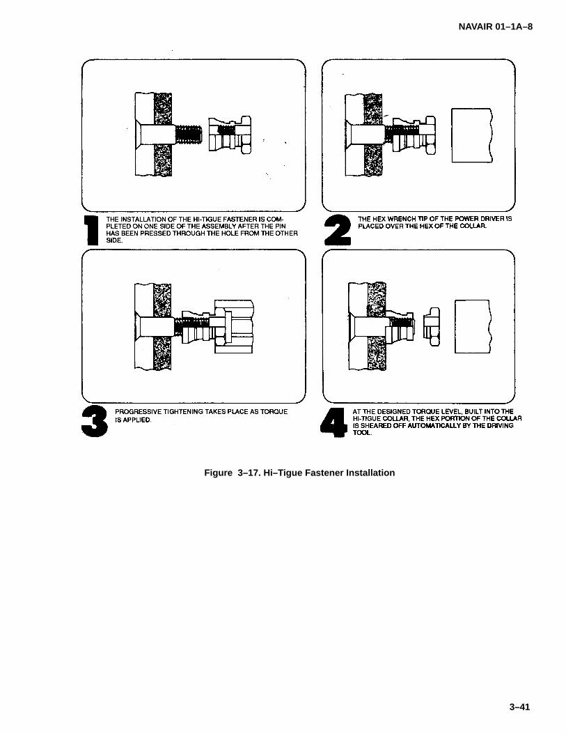
NAVAIR 01–1A–8
3–41
Figure 3–17. Hi–Tigue Fastener Installation
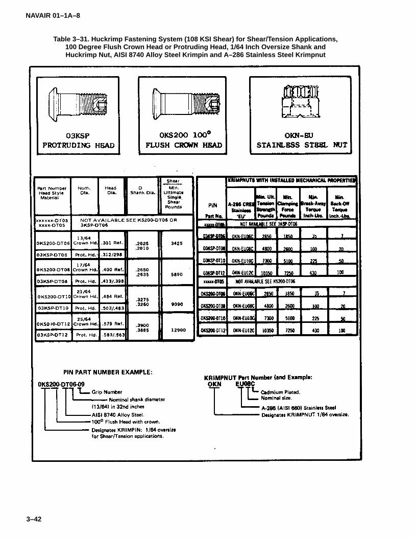
NAVAIR 01–1A–8
3–42
Table 3–31. Huckrimp Fastening System (108 KSI Shear) for Shear/Tension Applications,100 Degree Flush Crown Head or Protruding Head, 1/64 Inch Oversize Shank andHuckrimp Nut, AISI 8740 Alloy Steel Krimpin and A–286 Stainless Steel Krimpnut

NAVAIR 01–1A–8
3–43
Table 3–32. Huckrimp Fastening System (108 KSI Shear), 100 Degree Countersunk orProtruding Head, and Huckrimp Nuts for Shear Applications, AISI 8740 Alloy Steel
and 6AL–4V Pins with 2024 Aluminum Alloy Nuts

NAVAIR 01–1A–8
3–44
Table 3–33. Huckrimp Fastening System (108 KSI Shear), for Shear/Tension Applications,100 Degree Flush Crown Head or Protruding Head, AISI 8740 Alloy Steel Krimpin
and A–286 Stainless Steel Krimpnut
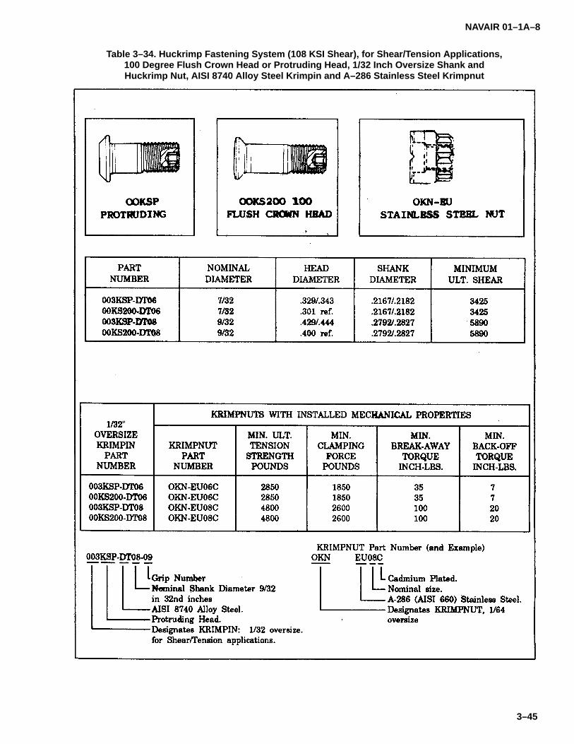
NAVAIR 01–1A–8
3–45
Table 3–34. Huckrimp Fastening System (108 KSI Shear), for Shear/Tension Applications,100 Degree Flush Crown Head or Protruding Head, 1/32 Inch Oversize Shank andHuckrimp Nut, AISI 8740 Alloy Steel Krimpin and A–286 Stainless Steel Krimpnut
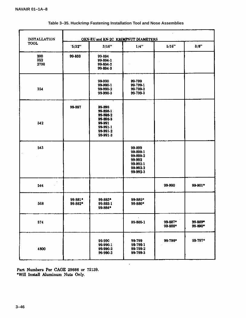
NAVAIR 01–1A–8
3–46
Table 3–35. Huckrimp Fastening Installation Tool and Nose Assemblies
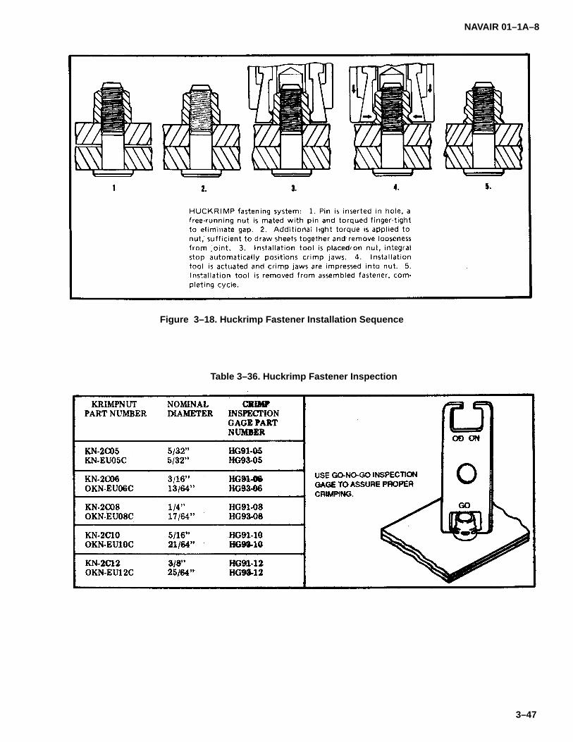
NAVAIR 01–1A–8
3–47
Figure 3–18. Huckrimp Fastener Installation Sequence
Table 3–36. Huckrimp Fastener Inspection
NAVAIR 01–1A–8
3–48
e. Blind fasteners shall not be used in the followingapplications:
1. Fluid–tight seams.
2. Control systems and operating devices/mechanisms.
3. Primary structure fittings.
4. Assemblies requiring frequent removal.
5. High vibrational areas.
6. Engine Inlet Areas/Components (exceptwhere authorized in specific T/M/S maintenance manu-als and manufacturers’ drawings).
3–61. BLIND FASTENER IDENTIFICATION. Blindfasteners are identified by a standard code number indi-cating fastener style, diameter, and maximum griplength. Table 3–37 lists several blind rivets and theirstandard code numbers. Blind rivet abbreviations in-clude MS (Military Standard), NAS (National AerospaceStandard), CR (Cherry Rivet), and RV (Olympic Rivet).An example of a blind rivet is MS20600AD5W3. Thisrepresents a self–plugging, 100� flush head rivet madeof 2117 aluminum alloy, with a serrated stem of5/32–inch diameter.
3–62. SUBSTITUTION OF BLIND FASTENERS FORCONVENTIONAL FASTENERS. Most blind fastenershave a lower level of reliability than conventional aircraftfasteners, particularly when inspection of the blind sideis not possible. Substitute blind fasteners for conven-tional fasteners in accordance with the requirements ofparagraph 3–60.
3–63. BLIND FASTENER PATTERN LAYOUT. Blindfasteners shall follow the same pattern as the originalinstallation if possible. As a general rule, follow the rivetpattern layout guidelines of paragraph 3–7.
3–64. SELF–PLUGGING, MECHANICALLYLOCKED RIVETS.
3–65. These rivets are available in universal(NAS1919) and 100� flush (NAS1921) head styles (re-fer to Table 3–38). They are manufactured fromaluminum alloy, CRES, and monel and are available in1/8, 5/32, 3/16, and 1/4–inch diameters.
3–66. SUBSTITUTION OF SELF–PLUGGING, ME-CHANICALLY LOCKED RIVETS FOR SOLID RIVETS.Maximum allowable loads for selfplugging, mechanical-ly locked rivets are comparable to those of solid rivets ofequal shear strength. Refer to Tables 3–39 and 3–40 forsubstitution data.
3–67. INSTALLATION TOOLS FOR SELF–PLUG-GING, MECHANICALLY LOCKED RIVETS.Installation tools and nose assemblies are listed in Table3–41. The tool nose consists of a set of chuck jawswhich fit the pull grooves of the rivet stem. A short noseassembly is available for areas without adequate clear-ance for the standard nose assembly.
3–68. INSTALLATION OF SELF–PLUGGING, ME-CHANICALLY LOCKED RIVETS. Use the followingprocedure for installing self–plugging, mechanicallylocked rivets:
a. Secure the sheets to be joined with temporaryfasteners.
b. Insert the proper diameter and grip length rivetinto hole.
c. Select appropriate installation tool and nose as-sembly from Table 3–41.
d. Place nose assembly over serrated pullgrooves and actuate tool. The stem will be sheared offand ejected.
3–69. INSPECTION OF SELF–PLUGGING, ME-CHANICALLY LOCKED RIVETS. Inspect the seating ofthe manufactured head visually. The locking collar andsheared pin end should be within the limits of Table3–42. Non–flush installations indicate improper griplength, and the rivet shall be replaced with the properlength rivet.
3–70. REMOVAL OF SELF–PLUGGING, MECHANI-CALLY LOCKED RIVETS. Remove self–plugging,mechanically locked rivets using the procedure of Fig-ure 3–19.
3–71. SELF PLUGGING, FRICTION LOCKED RIV-ETS.
3–72. Self–plugging, friction locked rivets are availablein universal (MS20600) and 1000 flush head (MS20601)styles (refer to Table 3–43) and are manufactured from2117 and 5056 aluminum alloys and monel. These blindrivets are available in 1/8, 5/32, 3/16, and 1/4–inch di-ameters.

NA
VAIR
01–1A–8
3–49
Table 3–37. C
herry an
d O
lymp
ic–Lo
k Rivet Id
entificatio
n

NA
VAIR
01–1A–8
3–50
Table 3–37. C
herry an
d O
lymp
ic–Lo
k Rivet Id
entificatio
n (C
on
tinu
ed)

NAVAIR 01–1A–8
3–51
Table 3–38. Self–plugging, Mechanically Locked Blind Rivets
Code:First dash number indicates diameter in 0.0312–inch increments.Second dash number indicates maximum grip in 0.0625–inch increments.B after basic part number indicates aluminum rivet.C after basic part number indicates A286 CRES rivet.M after basic part number indicates monel rivet.W after second dash number indicates cadmium–plated rivet sleeve.
Example of Part Number:NAS1919M05–04W = protruding head blind rivet, cadmium–plated monel, 5/32–inch diameter, 1/4–inch grip.

NAVAIR 01–1A–8
3–52
Table 3–39. Substitution Data for Aluminum Alloy Rivets
HOLE/RIVET SIZERIVET .129 TO .132 .160 TO .164 .192 TO .196
RIVET PART NO. MATERIAL .129 TO .132(1/8–INCH)
.160 TO .164(5/32–INCH)
.192 TO .196(5/16–INCH)
SHEAR TENS SHEAR TENS SHEAR TENS
MS20426DD
MS20470DD2024 531 — 815 — 1180 —
MS1919B*
MS1921B*5056 495 325 755 490 1090 715
NAS1399D*
NAS1398D*2017 494 230 755 375 1090 540
MS20426DF
MS20470DC2017 442 — 675 — 977 —
NAS1399B*
NAS1398B*5056 388 230 596 375 862 540
MS20462AD 2117 388 — 596 — 862 —
MS20600ADE*
MS20601ADE*2117 370 277 580 375 840 537
MS20602D*
MS20603D*2017 370 277 580 375 840 537
MS20426B
MS20470B5056 363 — 556 — 802 —
MS20600B*
MS20601B*
MS20602B*
MS20603B*
5056 360 227 560 375 810 537
MS20426A
MS20470AC1100 129 — 201 — 290 —
*Blind rivet.
Temperature Limitations:Aluminum Alloy Rivets: 250� F

NAVAIR 01–1A–8
3–53
Table 3–40. Substitution Data for CRES and Monel Rivets
HOLE/RIVET SIZERIVET
PART NO.RIVETMAT. .129 – .132
(1/8–INCH).160 – .164
(5/32–INCH).192 – .196
(5/16–INCH).256–.261
(1/4–INCH)
SHEAR TENS SHEAR TENS SHEAR TENS SHEAR TENS
NAS1919C*
NAS1921C*A286 1090 675 1670 1050 2400 1500 4250 2600
NAS1919M*
NAS1921M*MONEL 1020 675 1565 1050 2260 1500 4000 2600
NAS1398C*
NAS1399C*A286 970 640 1490 1000 2150 1500 3890 2700
MS20427FC
MS20615MDFS302 800 — 1248 — 1794 — 3192 800
NAS1398M*
NAS1399M*MONEL 710 340 1090 550 1580 780 2840 1450
MS20600ML
MS20601MLMONEL 670 227 1050 375 1520 537 2710 985
MS20427M
MS20615MMONEL 603 — 941 — 1352 — 2406 —
*Blind rivet.
Temperature Limitations:A286 CRES: 1200� FMonel: 900� FFS302: 800� FFS304: 800� F

NAVAIR 01–1A–8
3–54
Table 3–41. Self–plugging Blind Mechanical Lock Installation Tool and Nose Assembly
Table 3–42. Inspection Criteria for Self–plugging Rivets (Mechanical Lock)
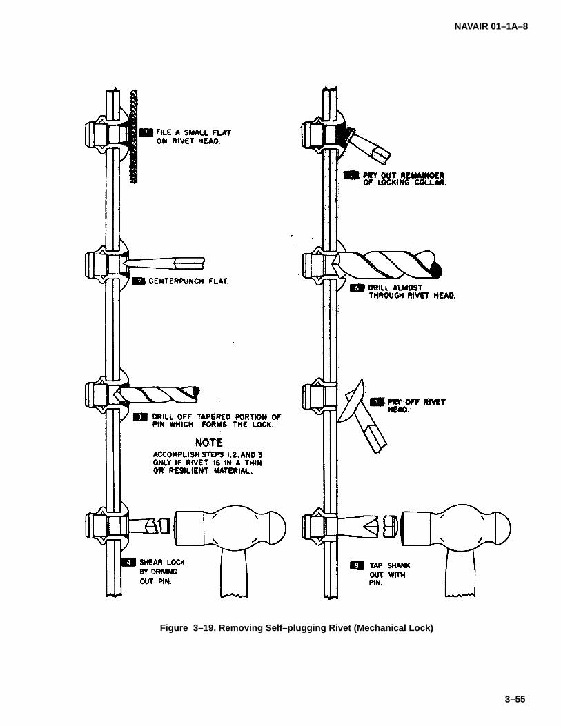
NAVAIR 01–1A–8
3–55
Figure 3–19. Removing Self–plugging Rivet (Mechanical Lock)

NAVAIR 01–1A–8
3–56
Table 3–43. Self–plugging, Friction Locked Blind Rivets
Code:Dash number indicates nominal diameter in 1/32–inch increments.AD before dash number indicates 2117 aluminum alloy rivet.B before dash number indicates 5056 aluminum alloy rivet.M before dash number indicates monel rivet.P before dash number indicates cadmium–plated rivet.
Examples of Part Numbers:MS20600–AD5W5 = 2117 aluminum alloy rivet, .156–inch serrated stem, .251 to .312–inch grip.MS20601–MP5W5 = cadmium–plated monel rivet, .156–inch serrated stem, .251 to .312–inch grip.
Material:2117 and 5056 aluminum alloys per QQ–A–430.Monel per QQ–N–281.
NAVAIR 01–1A–8
3–57
3–73. SUBSTITUTION OF SELF–PLUGGING, FRIC-TION LOCKED RIVETS FOR SOLID RIVETS.Self–plugging, friction locked rivets shall not be substi-tuted for solid rivets, nor shall they be used in criticalapplications, such as, control surface hinge brackets,wing attachment fittings, landing gear fittings, fluid–tightjoints, etc.
3–74. DETERMINATION OF SELF–PLUGGING,FRICTION LOCKED RIVET LENGTH. Self–plugging,friction locked rivets should protrude 3/64 to 1/8–inchthrough the substrate before drawing.
3–75. INSTALLATION TOOLS FOR SELF–PLUG-GING, FRICTION LOCKED RIVETS. Tooling availablefor installing self–plugging, friction locked rivets are theG–10 hand gun, the G–15 power gun, and the G–40power gun (see Figure 3–20). The G–10 hand gun andthe G–15 power gun utilize G–6H pulling heads. TheG–40 power gun uses H–40 pulling beads, or throughuse of a 226 adapter, G–6H pulling heads. Pullingheads are available in three different sizes to accommo-date all rivet diameters. Cherry H9015 and H9040series and Olympic RV355 and RV3355 series pullingbeads may be used to install self–plugging, serratedstem (MS20600/MS20601) rivets.
3–76. INSTALLATION OF SELF–PLUGGING, FRIC-TION LOCKED RIVETS. Ensure the proper drawbolt isused for the specific rivet being installed. Hold the instal-lation tool square to the surface. Installation is completewhen the stem breaks off (refer to Figure 3–21). Cut–offself–plugging, friction locked rivets using stem saws,hand nippers, or stem trimmers (see Figure 3–22).
3–77. INSPECTION OF SELF–PLUGGING, FRIC-TION LOCKED RIVETS. Visually inspect the blind sideof self–plugging, friction locked rivets when possible.Figure 3–23 shows examples of satisfactory and unsat-isfactory installations.
3–78. REMOVAL OF SELF–PLUGGING, FRICTIONLOCKED RIVETS. Refer to paragraph 3–93 for remov-al of blind rivets.
3–79. CHERRYLOCK BLIND RIVETS.
3–80. Cherrylock Standard (NAS1398/NAS1399) andCherrylock Bulbed (NAS1738/NAS1739) series blindrivets are locked spindle rivets consisting of a rivetsleeve, stem, and lockring collar. Cherrylock rivets are
available in universal and 100� flush shear head styles.The stem, sleeve, and lockring are available in severalcombinations of aluminum alloys, CRES, monel, and in-conel. Bulbed Cherrylock rivets are designed for thinsheet and dimpled applications.
3–81. CHERRYLOCK TOOLING. Cherrylock stan-dard and bulbed rivets may be installed with hand,hydroshift, or mechanical tooling systems. The hydro-shift tooling system has superseded the mechanicalsystem, and is recommended. Refer to Table 3–44 forCherry riveters, pulling heads, and suitable applica-tions.
a. Cherrylock Hand Tooling. The following areCherrylock hand riveters and adaptable pulling heads:
1. G36A Hand Riveter. This lightweight handriveter is used in hard to reach applications. It may beused to install most aluminum alloy rivets up to3/16–inch in diameter and smaller diameters of moneland CRES rivets. Use with the H615B series pullinghead.
2. G55 Hand Riveter. This heavy–duty handriveter is used to install most sizes and styles of blind riv-ets where power is not available. Use with the H640Bseries pulling head.
b. Cherrylock Hydroshift Tooling. The followingare Cherrylock Hydroshift riveters and adaptable pullingheads:
1. G700 Lightweight Power Riveter. Thislightweight power riveter generates 1200 Ibs pullingpower on 90 to 125 psi air pressure. It installs most smalldiameters of Cherrylock rivets. Use with the H681 se-ries pulling head.
2. G784 Universal Power Riveter. The G784power riveter generates 2650 lbs minimum pulling pow-er on 90 to 125 psi air pressure. It installs most sizes ofCherrylock rivets. Use with the H681 series pullinghead.
3. G685B–S and G686B–S Limited AccessPower Riveters. These ”split” riveters (i.e. the powerunit sits on the floor and transmits power to a lightweightgun) generate 2460 Ibs pulling power on 90 to 125 psiair pressure. They install most diameters of Cherrylockrivets. Use with the H681 series pulling heads.

NAVAIR 01–1A–8
3–58
Figure 3–20. Self–plugging Rivet (Friction Lock) Installation Tools
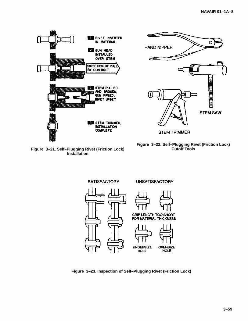
NAVAIR 01–1A–8
3–59
Figure 3–21. Self–Plugging Rivet (Friction Lock)Installation
Figure 3–22. Self–Plugging Rivet (Friction Lock)Cutoff Tools
Figure 3–23. Inspection of Self–Plugging Rivet (Friction Lock)

NAVAIR 01–1A–8
3–60
Table 3–44. Cherrylock ToolingThe numbers shown in the rivet columns below are the maximum grip length that can be installed with these tools.Shaded areas indicate those rivet sizes which cannot be installed in any grip.
(1) May require 95 psi air pressure at tool
(2) Superseded by hydroshift installation tools
(3) 3/32� A–286 (CR2662 & CR2663) rivets may be installed with any Cherry hydro–shift riveter equipped with anH681–3 pulling head
(4) G715A riveter only. G15 riveter will not set bulbed Cherrylocks
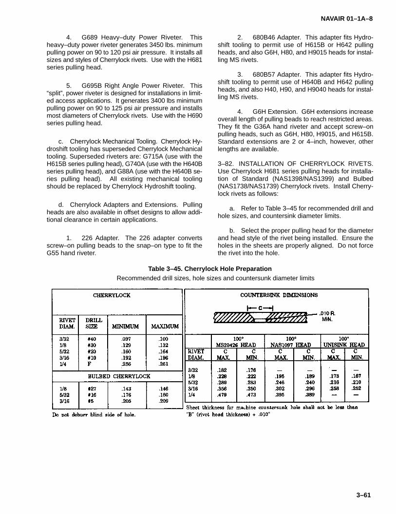
NAVAIR 01–1A–8
3–61
4. G689 Heavy–duty Power Riveter. Thisheavy–duty power riveter generates 3450 lbs. minimumpulling power on 90 to 120 psi air pressure. It installs allsizes and styles of Cherrylock rivets. Use with the H681series pulling head.
5. G695B Right Angle Power Riveter. This“split”, power riveter is designed for installations in limit-ed access applications. It generates 3400 lbs minimumpulling power on 90 to 125 psi air pressure and installsmost diameters of Cherrylock rivets. Use with the H690series pulling head.
c. Cherrylock Mechanical Tooling. Cherrylock Hy-droshift tooling has superseded Cherrylock Mechanicaltooling. Superseded riveters are: G715A (use with theH615B series pulling head), G740A (use with the H640Bseries pulling head), and G88A (use with the H640B se-ries pulling head). All existing mechanical toolingshould be replaced by Cherrylock Hydroshift tooling.
d. Cherrylock Adapters and Extensions. Pullingheads are also available in offset designs to allow addi-tional clearance in certain applications.
1. 226 Adapter. The 226 adapter convertsscrew–on pulling beads to the snap–on type to fit theG55 hand riveter.
2. 680B46 Adapter. This adapter fits Hydro-shift tooling to permit use of H615B or H642 pullingheads, and also G6H, H80, and H9015 heads for instal-ling MS rivets.
3. 680B57 Adapter. This adapter fits Hydro-shift tooling to permit use of H640B and H642 pullingheads, and also H40, H90, and H9040 heads for instal-ling MS rivets.
4. G6H Extension. G6H extensions increaseoverall length of pulling beads to reach restricted areas.They fit the G36A hand riveter and accept screw–onpulling heads, such as G6H, H80, H9015, and H615B.Standard extensions are 2 or 4–inch, however, otherlengths are available.
3–82. INSTALLATION OF CHERRYLOCK RIVETS.Use Cherrylock H681 series pulling heads for installa-tion of Standard (NAS1398/NAS1399) and Bulbed(NAS1738/NAS1739) Cherrylock rivets. Install Cherry-lock rivets as follows:
a. Refer to Table 3–45 for recommended drill andhole sizes, and countersink diameter limits.
b. Select the proper pulling head for the diameterand head style of the rivet being installed. Ensure theholes in the sheets are properly aligned. Do not forcethe rivet into the hole.
Table 3–45. Cherrylock Hole PreparationRecommended drill sizes, hole sizes and countersunk diameter limits

NAVAIR 01–1A–8
3–62
c. Place the pulling head on the rivet stem andhold the riveter flexibly in–line with the axis of the rivet.
d. Actuate the riveter applying a steady, light pres-sure. Inspect the stem after the rivet is installed.
3–83. CHERRYMAX BLIND RIVETS.
3–84. Cherrymax blind rivets consist of a fully–ser-rated stem with breaknotch, shear ring and integral gripadjustment cone, driving anvil, and rivet sleeve.Cherry–max rivets are available with universal or 100�flush head in several combinations of alloy steel, alumi-num alloy, CRES and monel. Cherrymax nominaldiameter rivets use the same hole size as StandardCherrylock (NAS1398/NAS1399) rivets and Cherrymaxoversize diameter rivets use the same hole size asBulbed Cherrylock (NAS1738/NAS1739) rivets.
3–85. CHERRYMAX TOOLING. Cherrymax hand andpneumatic–hydraulic tools are specifically designed forinstalling Cherrymax fasteners. Refer to Table 3–46 forCherry riveters, pulling heads, and applications.
a. Cherrymax Hand Tooling. The following de-scribes Cherrymax hand riveters:
1. G27 Hand Riveter. This lightweight handriveter is available for limited use. It may be used toinstall 14 nominal and oversize blind rivets. The pullinghead is an integral part of this riveter.
2. G749A Hand Riveter. This hydraulic handriveter is effective where power is not available. Referto Table 3–46 for applications and adaptable pullingheads.
b. Cherrymax Power Tooling. The following areCherrymax power riveters:
1. G701A Power Riveter. This riveter gener-ates 1614 lbs pulling power on 90 psi air pressure.Pulling heads are listed in Table 3–46.
2. G704B Power Riveter. This riveter gener-ates 3136 lbs pulling power on 90 psi air pressure. Itmay be used to install all Cherrymax rivets except for –8size. Refer to Table 3–46 for pulling heads.
3. G744 Power Riveter. This riveter gener-ates 3800 lbs pulling power on 90 psi air pressure. Itmay be used to install –8 Cherrymax rivets. Refer toTable 3–46 for pulling heads.
c. Cherrymax Adapters and Extensions. The fol-lowing adapters and extensions may be used withCherrymax tooling:
1. 704A6 and H704A9 Adapters. Theseadapters permit the use of H6040 snap–on and H9015pulling heads, respectively. They may be used onG701A, G704B, and G749A Cherrymax riveters.
2. 680B202 Adapter. This adapter permits theG686B–S, G689, G700, and G784 riveters to acceptH753A–456 and H753–456 pulling heads for installing1/8, 5/32 and 3/16–inch Cherrymax rivets.
3. 744A20 Adapter. This adapter permits theG744 riveter to accept the H701–456, H753–456, andH763–456 pulling heads for installing 1/8, 5/32, and3/16–inch Cherrymax rivets.
4. 740A26 Adapter. This adapter permits theG740A and G86A riveters to accept the H749A–456,H753A–456 and H763–456 pulling heads for installing1/8, 5/32 and 3/16–inch Cherrymax rivets.
5. 704A12 Extension. This extension fitsG701A, G704B, and G749A Cherrymax riveters. Theywill accept any of the pulling heads listed for these rivet-ers in Table 3–46.
6. 744B35 Extension. This extension fits theG744 riveter and will accept any of the pulling headslisted for that riveter in Table 3–46.
7. 735B21 Extension. The 735121 extensionincreases the overall length of the H753A–456 90� pull-ing head to approximately 2–3/16–inch.
3–86. INSTALLATION OF CHERRYMAX RIVETS.Use Cherrymax H701A456, H763, and H753 pullingheads for installing Cherrymax (CR3242/CR3243 andCR3252/CR3253) rivets. Install Cherrymax blind rivetsas follows:
a. Refer to Table 3–47 for drill and hole sizes, andcountersink diameters for standard and oversize Cher-rymax rivets.
b. Check drilled hole size with Cherry T–172 RivetHole Size Gage (refer to Table 3–48). The T–172 gageis a precision ground, ”go no–go” gage available in allstandard and oversize rivet diameters.
c. Insert rivet in prepared hole. Do not force rivetif sheets are misaligned.
d. Lightly hold riveter in–line with rivet axis and ac-tuate. The rivet is completely installed when the stembreaks off.

NAVAIR 01–1A–8
3–63
3–87. OLYMPIC–LOK BLIND RIVETS.
3–88. Olympic–Lok blind rivets are non–shifting rivetsconsisting of a sleeve, stem, and spindle–locking collar.They are available in both standard and bulbed styleswith universal and 100� flushheads. Standard Olym-pic–Loks are available in 1/8, 5/32, 3/16, and 1/4–inchdiameters. Bulbed Olympic–Loks are available in1/64–inch oversize diameters of 1/8, 5/32, and3/16–inch. Both styles are manufactured in severalcombinations of aluminum alloys, CRES, and monel.
3–89. OLYMPIC TOOLING. Olympic blind fastenerinstallation tools are available in hand, pneumatic andpneumatic–hydraulic, and electric types.
a. Olympic Hand Riveters. The following areOlympic hand riveters:
1. RV9G Hand Riveter. This plier–type riveteris available with threaded nose inserts for installing most–3, –4, and –5 MS rivets. The RV9GBB riveter is usedto install RV6604–5/6 Bulb–Tite rivets. The RV9GLhand riveter is used to install –4 Olympic locked spindlerivets.
2. RV28GA Hand Riveter. This two–handedcrank gun is operated by rotating the handle one com-plete revolution. This riveter accepts all Group II(snap–on) pulling heads without adapters.
3. RV36GA Hand Riveter. This ratchet–typetool installs most 3/16–inch and smaller rivets. It ac-cepts all Group I (screw–on) pulling heads withoutadapters.
b. Pneumatic and Pneumatic–Hydraulic Riveters.All pneumatic units accept Group I (screw–on) pullingheads directly and Group II (snap–on) pulling headswith an RVA30 adapter. The following are pneumaticand pneumatic–hydraulic power riveters:
1. RV51G Pneumatic Riveter. This light-weight riveter is designed for high speed installation ofintermediate diameter fasteners. Its pulling capacity is910 to 1250 lbs at 80 to 110 psi air pressure.
2. RV50G Pneumatic Riveter. This riveter issimilar to the RV51G, except it has a pulling power of600 to 830 lbs at 80 to 110 psi air pressure.
3. RV14G Pneumatic–Hydraulic Riveter. Thislightweight power riveter may be used to install mostsmall and intermediate diameter rivets. Its pulling ca-pacity is 1400 to 2000 lbs at 80 to 110 psi air pressure.
4. RV30G Pneumatic–Hydraulic Riveter. Thisheavy–duty power unit may be used to install most
Olympic fasteners through 9/32–inch diameter. Its pull-ing capacity is 2800 to 3800 lbs at 80 to 110 psi airpressure.
c. Olympic Electric Riveter. Olympic electric rivet-ers are designed for field application where pneumaticpower is unavailable. All electric units accept Group II(snap–on) pulling heads directly or Group I (screw–on)pulling heads with an RVA802 adapter. The followingare electric riveters:
1. RV72G Electric Riveter. This lightweightriveter may be used to install most large diameter fas-teners. Pulling capacity is 1900 lbs.
2. RV78G Electric Riveter. This heavy dutyriveter has a fiberglass–reinforced shock protected ny-lon ”D” handle and a pulling capacity of 3000 lbs.
3. RV70EC Electric Riveter. This unit threadsdirectly onto the shaft of most drill motors. It has a maxi-mum pulling capacity of 1600 lbs.
3–90. INSTALLATION OF OLYMPIC–LOK BLINDRIVETS. Olympic RV812 series pulling heads shall beused to install Olympic–Lok (NAS1398/NAS1399 ”A”Code) and Olympic Bulb–Lok (NAS1768/NAS1769) riv-ets.
3–91. BLIND RIVET INSPECTION.
3–92. Inspect installed blind rivets using the followingprocedure:
a. Cherry Rivets. Visually inspect the blind side,if possible. Perform stem push–out test by applyingapproximately 10 pounds of pressure to the spindle. Ifthe stem moves, replace rivet. Flathead rivets may havea maximum gap of 0.008–inch on one side of the beadonly; the other side must be seated. Brazier head rivetsmay have a 0.003–inch gap if not more than 40% ofhead circumference is gapped. Flush head rivets shallnot be more than 0.004–inch below the surface, normore than 0.011–inch above the surface. If these limitsare exceeded, replace the rivet.
b. Trimmed Stems. Removal of the spindle afterinstallation may be accomplished by using a power stemtrimmer or a flush, side cutting nipper. Cherry Part No.220, 225, or 301B power trimmer or Cherry Part No. 209hand trimmer may be used. An alternate choice is a pairof diagonal cutting pliers ground flush on one side.Sanding discs or grinding wheels shall not be used fortrimming rivet stems. Trimmed stems of flush and bra-zier head rivets shall not protrude more than 0.010–inchabove the head in exterior installations. Mill or file sharpedges remaining after trimming. Remove no more than0.005–inch from a rivet head.

NAVAIR 01–1A–8
3–64
Table 3–46. Cherrymax ToolingThe tool and pulling head combinations shown in the chart below will install the diameter rivets indicated by theshaded areas, in all grip lengths, head styles and materials except as noted.
CHERRY PULLINGALL GRIP LENGTHS, HEAD STYLES & MATERIALS EXCEPT AS NOTED
CHERRYRIVETER
PULLINGHEAD NOMINAL DIAMETER OVERSIZE DIAMETER
MODEL NUMBER –4 –5 –6 –8 –4 –5 –6 –8
G27
*H9015–3CG36A
*H9015–4C
*H9040–4CG86A
*H9040–6C
G686B–S H680B200A
H680B200AG689
H680B208
G700 H680B200A
H701B–456
H753A–456G701A
H763–456
G704B H701B–456
G704B–40SH H753A–456
G704B–SR H763–456
*H9015–3C
G715A *H9015–4C
*9015–4C
*H9040–4CG740A
*H9040–5C
H744A–8
G744 H827–8
G744–85SH H828–8
H846A–456
H749A–456
H753A–456G749A
H763–456
H479A–8
H680B200AG784
H680B208
* CAUTION – When using H9015 and H9040 pulling heads always point ejection slot away asstem is ejected forcefully.
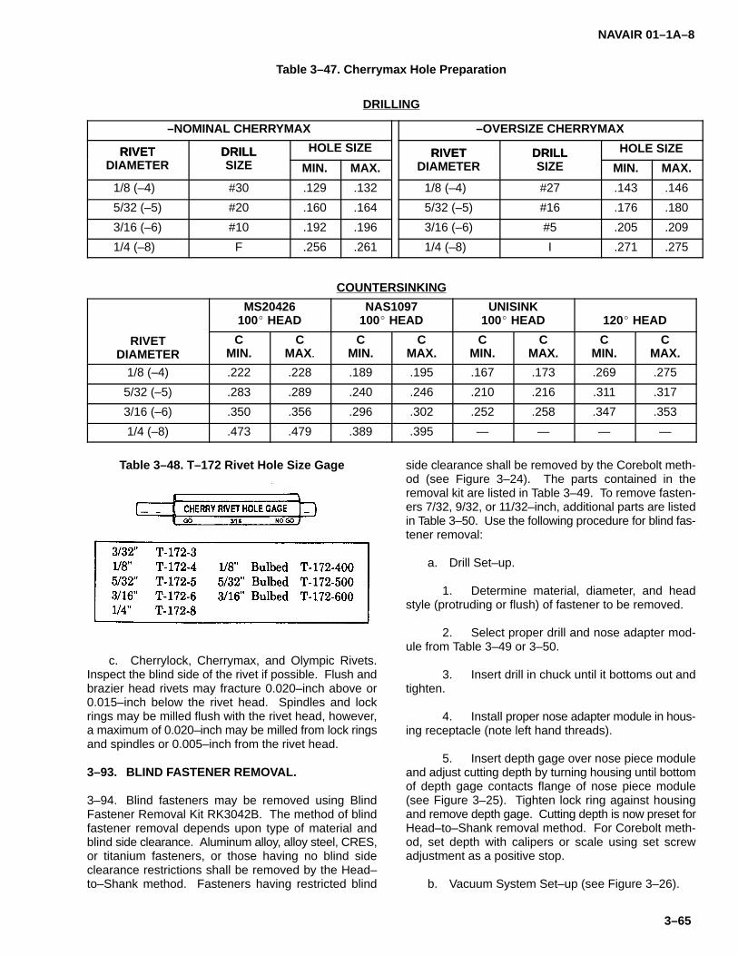
NAVAIR 01–1A–8
3–65
Table 3–47. Cherrymax Hole Preparation
DRILLING
–NOMINAL CHERRYMAX –OVERSIZE CHERRYMAX
RIVET DRILL HOLE SIZE RIVET DRILL HOLE SIZERIVETDIAMETER
DRILLSIZE MIN. MAX.
RIVETDIAMETER
DRILLSIZE MIN. MAX.
1/8 (–4) #30 .129 .132 1/8 (–4) #27 .143 .146
5/32 (–5) #20 .160 .164 5/32 (–5) #16 .176 .180
3/16 (–6) #10 .192 .196 3/16 (–6) #5 .205 .209
1/4 (–8) F .256 .261 1/4 (–8) I .271 .275
COUNTERSINKING
MS20426100� HEAD
NAS1097100� HEAD
UNISINK100� HEAD 120� HEAD
RIVETDIAMETER
CMIN.
CMAX.
CMIN.
CMAX.
CMIN.
CMAX.
CMIN.
CMAX.
1/8 (–4) .222 .228 .189 .195 .167 .173 .269 .275
5/32 (–5) .283 .289 .240 .246 .210 .216 .311 .317
3/16 (–6) .350 .356 .296 .302 .252 .258 .347 .353
1/4 (–8) .473 .479 .389 .395 — — — —
Table 3–48. T–172 Rivet Hole Size Gage
c. Cherrylock, Cherrymax, and Olympic Rivets.Inspect the blind side of the rivet if possible. Flush andbrazier head rivets may fracture 0.020–inch above or0.015–inch below the rivet head. Spindles and lockrings may be milled flush with the rivet head, however,a maximum of 0.020–inch may be milled from lock ringsand spindles or 0.005–inch from the rivet head.
3–93. BLIND FASTENER REMOVAL.
3–94. Blind fasteners may be removed using BlindFastener Removal Kit RK3042B. The method of blindfastener removal depends upon type of material andblind side clearance. Aluminum alloy, alloy steel, CRES,or titanium fasteners, or those having no blind sideclearance restrictions shall be removed by the Head–to–Shank method. Fasteners having restricted blind
side clearance shall be removed by the Corebolt meth-od (see Figure 3–24). The parts contained in theremoval kit are listed in Table 3–49. To remove fasten-ers 7/32, 9/32, or 11/32–inch, additional parts are listedin Table 3–50. Use the following procedure for blind fas-tener removal:
a. Drill Set–up.
1. Determine material, diameter, and headstyle (protruding or flush) of fastener to be removed.
2. Select proper drill and nose adapter mod-ule from Table 3–49 or 3–50.
3. Insert drill in chuck until it bottoms out andtighten.
4. Install proper nose adapter module in hous-ing receptacle (note left hand threads).
5. Insert depth gage over nose piece moduleand adjust cutting depth by turning housing until bottomof depth gage contacts flange of nose piece module(see Figure 3–25). Tighten lock ring against housingand remove depth gage. Cutting depth is now preset forHead–to–Shank removal method. For Corebolt meth-od, set depth with calipers or scale using set screwadjustment as a positive stop.
b. Vacuum System Set–up (see Figure 3–26).

NAVAIR 01–1A–8
3–66
NOTE
Hex head fasteners may not require thevacuum pad. The hex nut nose piece ofthe nose adapter will keep the drill cen-tered.
1. Connect drill motor to power pack with airhose. (Drill motor may be connected to alternate air sup-ply).
2. Connect vacuum pad to power pack withvacuum hose.
3. Connect air supply (80 psi min) to powerpack.
c. Vacuum Pad Indexing.
1. Center vacuum pad by inserting index pin(refer to Table 3–50) through center of vacuum pad andengage with the fastener recess (see Figure 3–27).
2. Double check centering by rotating the in-dex pin through the four quadrants. The pin should dropinto the recess with each 1/4 turn if properly aligned.Should vacuum pad require repositioning, depress pop-pet valve button on vacuum pad handle to temporarilydisconnect vacuum supply. Reposition using proper in-dex pin.
d. Drilling Procedure.
1. Insert nose of drill through vacuum pad andcarefully engage fastener recess with the nose.
CAUTION
Do not touch fastener with drill bit until mo-tor has been brought up to full RPM, or drillbit may chip.
2. Bring drill motor up to full RPM and drill fas-tener until gap is closed between nose flange andreceptacle (see Figure 3–28). This may be determinedvisually or audibly by an increase in the RPM of the drillmotor.
3. Remove drill and vacuum pad.
e. Fastener Knockout.
1. Select proper rivet set (refer to Table 3–51)and insert in rivet gun.
2. Connect rivet gun to air hose, moderatethrottle control and knock out fastener (see Figure3–29).
NOTEIf several fasteners of one diameter re-quire removal, repeat steps (c) and (d)until all fasteners have been drilled, thenrepeat step (e) to knockout all fasteners.
Figure 3–24. Fastener Removal Methods

NAVAIR 01–1A–8
3–67
Table 3–49. Blind Fastener Removal Kit
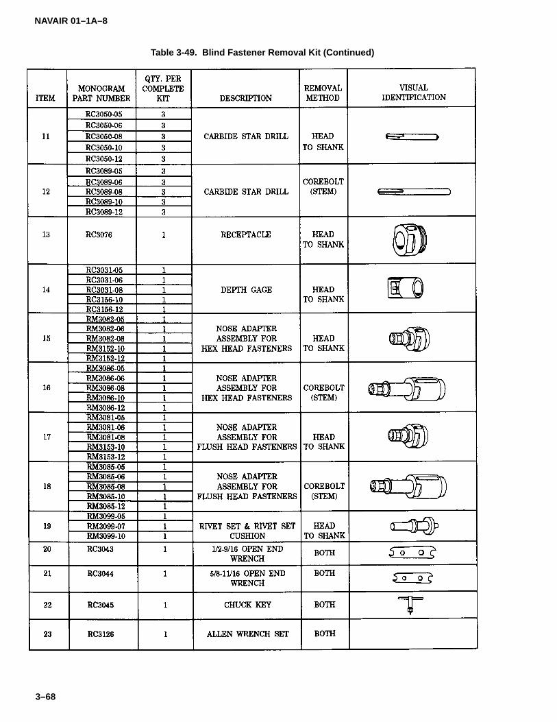
NAVAIR 01–1A–8
3–68
Table 3-49. Blind Fastener Removal Kit (Continued)
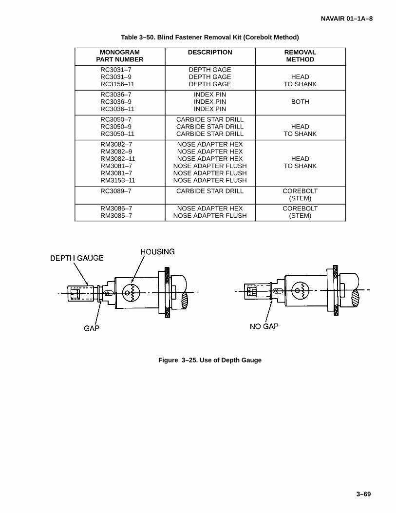
NAVAIR 01–1A–8
3–69
Table 3–50. Blind Fastener Removal Kit (Corebolt Method)
MONOGRAMPART NUMBER
DESCRIPTION REMOVALMETHOD
RC3031–7RC3031–9RC3156–11
DEPTH GAGEDEPTH GAGEDEPTH GAGE
HEADTO SHANK
RC3036–7RC3036–9RC3036–11
INDEX PININDEX PININDEX PIN
BOTH
RC3050–7RC3050–9RC3050–11
CARBIDE STAR DRILLCARBIDE STAR DRILLCARBIDE STAR DRILL
HEADTO SHANK
RM3082–7RM3082–9RM3082–11RM3081–7RM3081–7RM3153–11
NOSE ADAPTER HEXNOSE ADAPTER HEXNOSE ADAPTER HEX
NOSE ADAPTER FLUSHNOSE ADAPTER FLUSHNOSE ADAPTER FLUSH
HEADTO SHANK
RC3089–7 CARBIDE STAR DRILL COREBOLT(STEM)
RM3086–7RM3085–7
NOSE ADAPTER HEXNOSE ADAPTER FLUSH
COREBOLT(STEM)
Figure 3–25. Use of Depth Gauge

NAVAIR 01–1A–8
3–70
Figure 3–26. Vacuum System
Figure 3–27. Vacuum Pod Indexing

NAVAIR 01–1A–8
3–71
Figure 3–28. Drilling
Table 3–51. Rivet Sets
Figure 3–29. Knockout

NAVAIR 01–1A–8
3–72
3–95. INTERCHANGEABILITY OF CHERRY ANDOLYMPIC RIVETS.
3–96. The following provides Cherry and Olympic rivetinterchangeability requirements:
a. NAS1398/NAS1399 series rivets may be sub-stituted for MS20600 rivets. NAS1738/NAS1739 orNAS1768/NAS1769 series rivets may be used if thehole is enlarged to accept the oversize rivet.
b. CR3242/CR3243 series rivets may be substi-tuted for NAS1738/NAS1739 or NAS1768/NAS1769series rivets.
c. Cherrylock and Olympic-Lok rivet conversionsare provided in Table 3-52.
3–97. MILITARY STANDARD BLIND BOLTS.
3–98. Military Standard (MS) blind bolts are highstrength, positive locking fasteners designed for use inblind applications (refer to Tables 3-53 and 3-54).
3–99. INSTALLATION OF MS BLIND BOLTS. Installa-tion tools are listed in Table 3–55. Use installationprocedure outlined in Figure 3-30.
3–100. INSPECTION OF MS BLIND BOLTS. Inspectblind bolt locking collars and spindle positions to ensurethey are within the limits of Figure 3-31.
3–101. REMOVAL OF MS BLIND BOLTS. Remove MSblind bolts using the procedure in Table 3-56.
3–102. SUBSTITUTION CHARTS FOR BLIND FAS-TENERS.
3–103. Substitution of alloy steel and CRES blind fas-teners shall be in accordance with Tables 3-57 and 3-58.
3–104. JO-BOLT (VISU-LOK) FASTENERS.
3–105. Jo-Bolts, also known as Visu-Loks, offer stan-dard or oversize tapered shank configurations (refer toTable 3-59). They are used in severe fatigue applica-tions, close-tolerance straight shank interferenceconfigurations, and reduced head configurations. Jo-Bolts consist of a preassembled nut, a threaded bolt,and a sleeve. They are manufactured from alloy steel,
aluminum alloy, high strength steel, CRES, titanium,and inconel.
3–106. JO-BOLT HOLE PREPARATION. Table 3-60provides hole sizes for standard and oversize Jo-Bolts,and countersink diameters for flush head Jo-Bolts.
3–107. JO-BOLT INSTALLATION TOOLS. Install Jo-Bolts with hand or pneumatic drivers (see Figure 3-32)used in conjunction with a nose adapter and wrenchadapter. The nose adapter prevents the Jo-Bolt fromturning during installation. Millable head Jo-Bolts maybe shaved flush using a standard 1-inch rivet shaverwith a carbide cutter turning at 10,000 RPM minimum.
3–108. INSTALLATION OF JO-BOLTS. Install Jo-Boltsas follows:
NOTE
Jo-Bolts are pre-lubricated. Do not re-move lubrication from Jo-Bolts beforeinstallation. No paint or primer shall beapplied to Jo-Bolts before they areinstalled unless otherwise specified.
a. Secure structure to be joined with temporaryfasteners.
b. Insert the proper size Jo-Bolt into the hole. Iffastener must be forced into the hole, ream until fit is cor-rect. A light tap fit is permissible in aluminum alloys.
c. Select proper nose and wrench adapter forhand or power gun. Adapters for hand and power gunsare not interchangeable. Place the nose adapter overthe bolt shank to engage the head of the Jo-Bolt. Onflush head Jo-Bolts, ensure the tabs on the nose adapt-er engage the slots on the fastener head.
d. Hold gun square to the surface and actuate.The stem will break off when the sleeve is drawn up tight.
3–109. INSPECTION OF JO-BOLTS. Visually inspectJo-Bolt collars after installation, if possible. Replacefasteners with split or buckled collars. Check stembreak-off with Jo-Bolt stem break-off gage per Figure3-33. If stem is not within the limits of Figure 3-33, thefastener is of incorrect grip length or was driven improp-erly and shall be replaced. Replace Jo-Bolts with a0.005-inch or greater gap under the head.

NAVAIR 01–1A–8
3–73
Table 3–52. Cherrylock and Olympic-Lok Rivet Conversion Chart
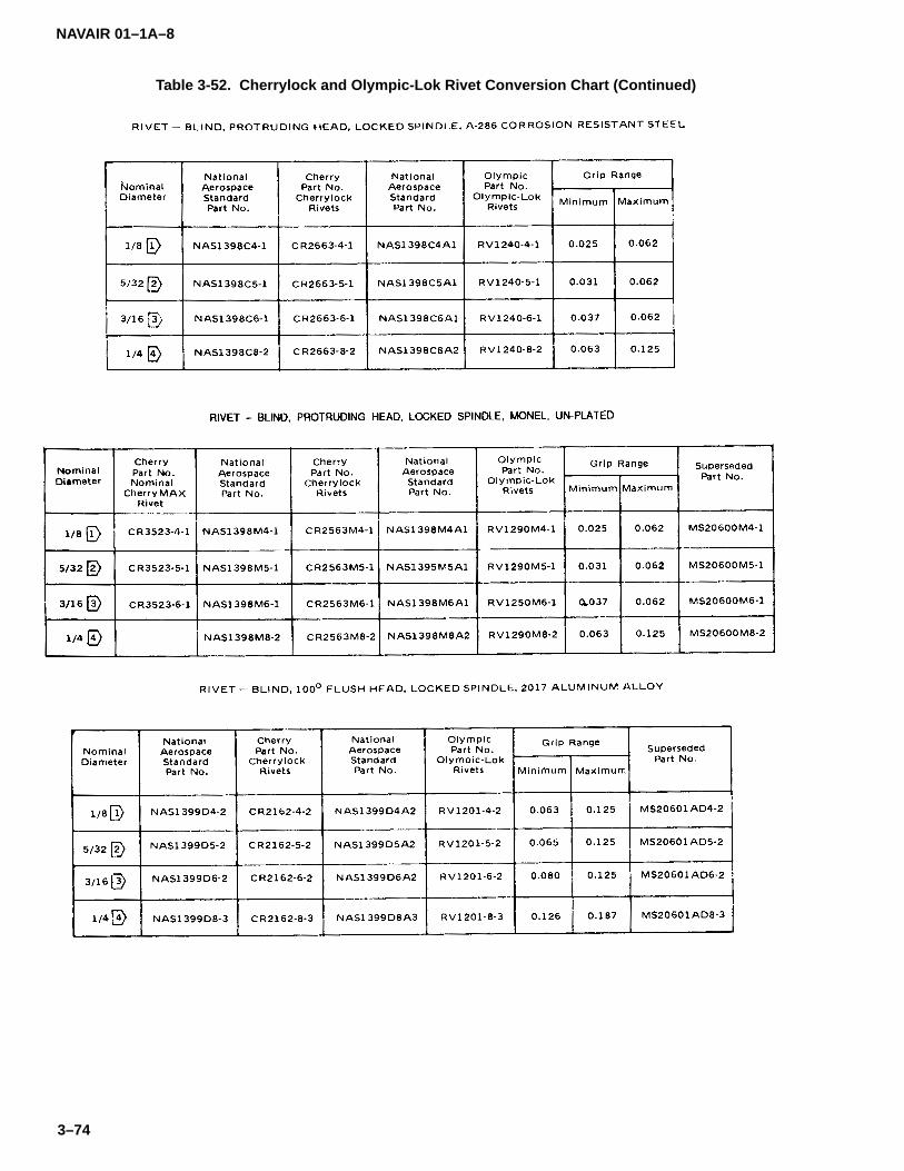
NAVAIR 01–1A–8
3–74
Table 3-52. Cherrylock and Olympic-Lok Rivet Conversion Chart (Continued)

NAVAIR 01–1A–8
3–75
Table 3-52. Cherrylock and Olympic-Lok Rivet Conversion Chart (Continued)

NAVAIR 01–1A–8
3–76
Table 3-52. Cherrylock and Olympic-Lok Rivet Conversion Chart (Continued)
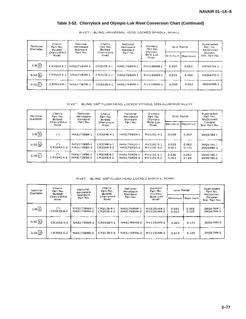
NAVAIR 01–1A–8
3–77
Table 3-52. Cherrylock and Olympic-Lok Rivet Conversion Chart (Continued)

NAVAIR 01–1A–8
3–78
Table 3-52. Cherrylock and Olympic-Lok Rivet Conversion Chart (Continued)

NAVAIR 01–1A–8
3–79
Table 3–53. MS21141 and MS90354 Pull-type Blind Fasteners
Code:– before dash number indicates fastener installed with double action tool for sizes 05 and 06, or fastener installedwith single action tool for sizes 08, 10, 12, 14, and 16.S before dash number indicates fastener installed with single action tool for sizes 05 and 06.U before dash number indicates fastener installed with single action tool for all sizes.D after dash number indicates aluminum coated alloy steel fastener.P after dash number indicates cadmium–plated CRES fastener.
Examples of Part Numbers:MS21141–0803P = 1/4–inch diameter, .156–inch grip length, cadmium–plated fastener installed with a single ac-tion tool.MS90354–806D = 1/4–inch diameter, .156–inch grip length fastener installed with a single action tool.
Material:Carbon Steel or Alloy Steel (1010, 1020, 1144, 4037, or 4130 per Federal Standard 66 (MS90354).CRES per AMS5737 (MS21141).

NAVAIR 01–1A–8
3–80
Table 3–54. MS21140 and MS90353 Pull-type Blind Fasteners
Code:– before dash number indicates fastener installed with double action tool for sizes 05 and 06, or fastener installedwith single action tool for sizes 08, 10, 12, 14, and 16.S before dash number indicates fastener installed with single action tool for sizes 05 and 06.U before dash number indicates fastener installed with single action tool for all sizes.D after dash number indicates aluminum coated alloy steel fastener.P after dash number indicates cadmium–plated CRES fastener.
Examples of Part Numbers:MS21140–0803P = 1/4–inch diameter, .156–inch grip length, cadmium–plated fastener installed with a singleaction tool.MS90353–806D = 1/4–inch diameter, .156–inch grip length fastener installed with a single action tool.
Material:Carbon Steel or Alloy Steel (1010, 1020, 1144, 4037, or 4130 per Federal Standard 66 (MS90353).CRES per AMS5737 (MS21140).

NAVAIR 01–1A–8
3–81
Table 3–55. Blind Bolt Installation Tools and Nose Assemblies
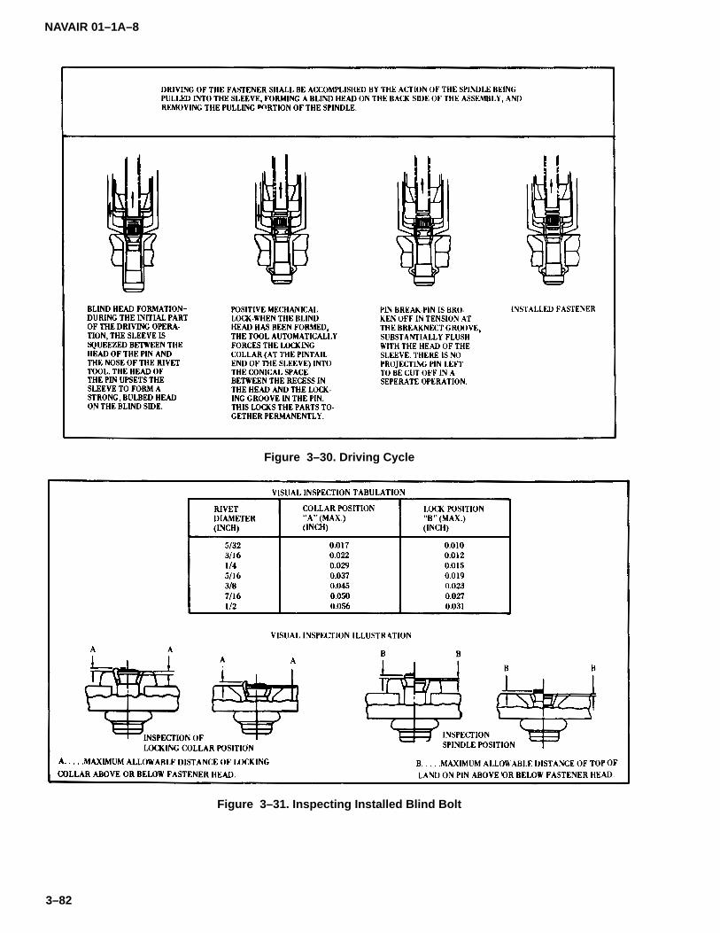
NAVAIR 01–1A–8
3–82
Figure 3–30. Driving Cycle
Figure 3–31. Inspecting Installed Blind Bolt

NAVAIR 01–1A–8
3–83
Table 3–56. Blind Bolt Removal

NAVAIR 01–1A–8
3–84
Table 3–57. Substitution Data for Non-hole Filling Alloy Steel Blind Fasteners
Table 3–58. Substitution Data for Non-hole Filling CRES Blind Fasteners
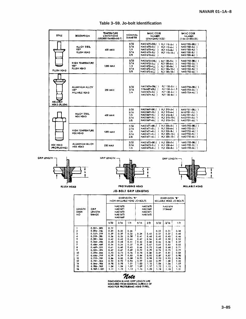
NAVAIR 01–1A–8
3–85
Table 3–59. Jo-bolt Identification
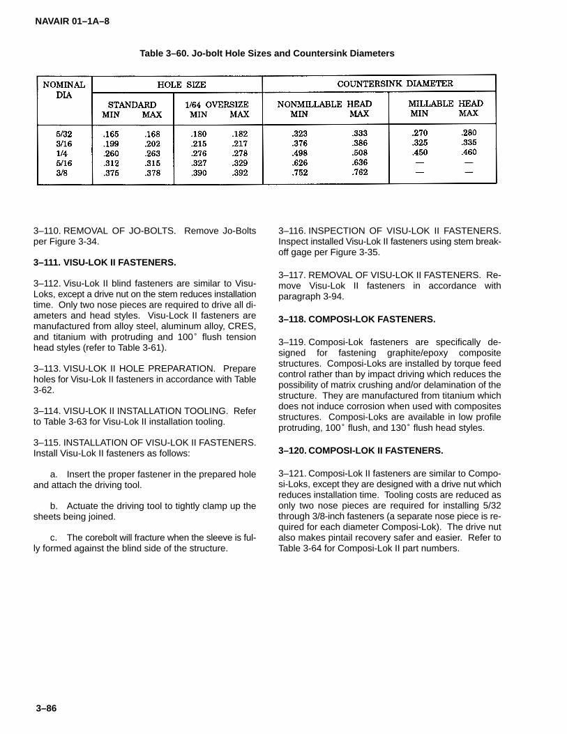
NAVAIR 01–1A–8
3–86
Table 3–60. Jo-bolt Hole Sizes and Countersink Diameters
3–110. REMOVAL OF JO-BOLTS. Remove Jo-Boltsper Figure 3-34.
3–111. VISU-LOK II FASTENERS.
3–112. Visu-Lok II blind fasteners are similar to Visu-Loks, except a drive nut on the stem reduces installationtime. Only two nose pieces are required to drive all di-ameters and head styles. Visu-Lock II fasteners aremanufactured from alloy steel, aluminum alloy, CRES,and titanium with protruding and 100� flush tensionhead styles (refer to Table 3-61).
3–113. VISU-LOK II HOLE PREPARATION. Prepareholes for Visu-Lok II fasteners in accordance with Table3-62.
3–114. VISU-LOK II INSTALLATION TOOLING. Referto Table 3-63 for Visu-Lok II installation tooling.
3–115. INSTALLATION OF VISU-LOK II FASTENERS.Install Visu-Lok II fasteners as follows:
a. Insert the proper fastener in the prepared holeand attach the driving tool.
b. Actuate the driving tool to tightly clamp up thesheets being joined.
c. The corebolt will fracture when the sleeve is ful-ly formed against the blind side of the structure.
3–116. INSPECTION OF VISU-LOK II FASTENERS.Inspect installed Visu-Lok II fasteners using stem break-off gage per Figure 3-35.
3–117. REMOVAL OF VISU-LOK II FASTENERS. Re-move Visu-Lok II fasteners in accordance withparagraph 3-94.
3–118. COMPOSI-LOK FASTENERS.
3–119. Composi-Lok fasteners are specifically de-signed for fastening graphite/epoxy compositestructures. Composi-Loks are installed by torque feedcontrol rather than by impact driving which reduces thepossibility of matrix crushing and/or delamination of thestructure. They are manufactured from titanium whichdoes not induce corrosion when used with compositesstructures. Composi-Loks are available in low profileprotruding, 100� flush, and 130� flush head styles.
3–120. COMPOSI-LOK II FASTENERS.
3–121. Composi-Lok II fasteners are similar to Compo-si-Loks, except they are designed with a drive nut whichreduces installation time. Tooling costs are reduced asonly two nose pieces are required for installing 5/32through 3/8-inch fasteners (a separate nose piece is re-quired for each diameter Composi-Lok). The drive nutalso makes pintail recovery safer and easier. Refer toTable 3-64 for Composi-Lok II part numbers.
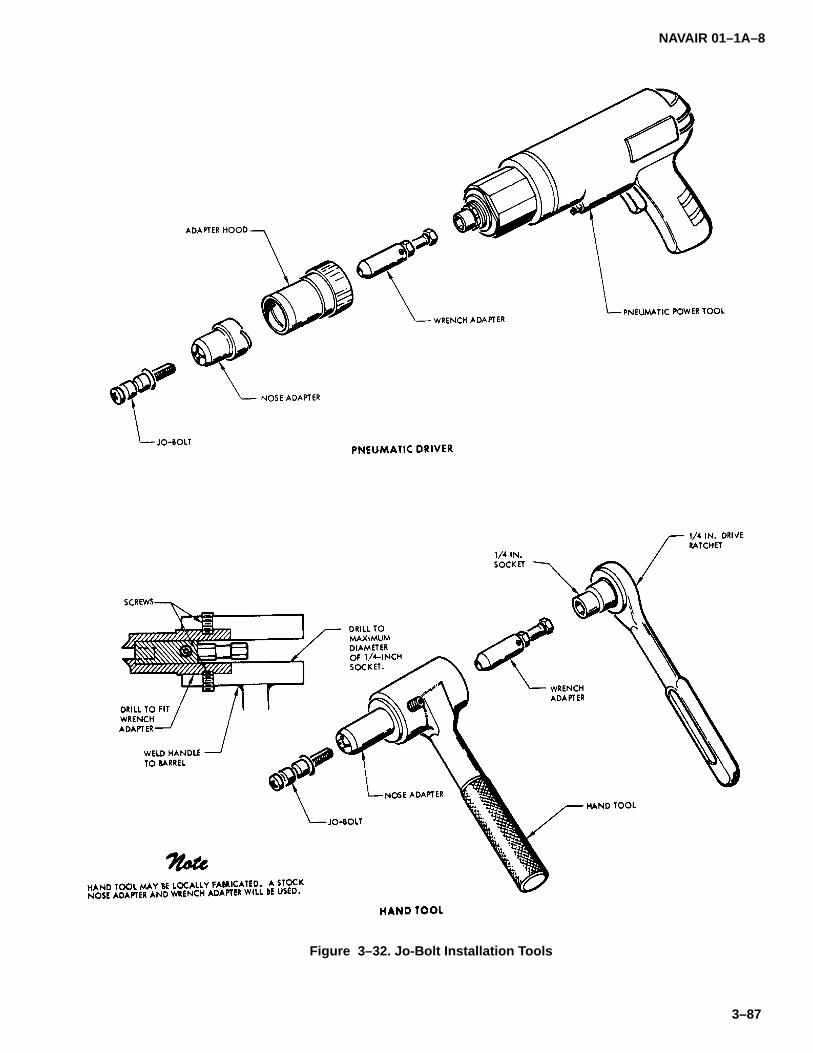
NAVAIR 01–1A–8
3–87
Figure 3–32. Jo-Bolt Installation Tools
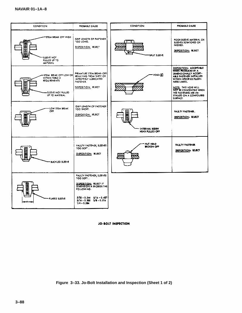
NAVAIR 01–1A–8
3–88
Figure 3–33. Jo-Bolt Installation and Inspection (Sheet 1 of 2)
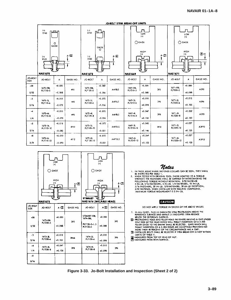
NAVAIR 01–1A–8
3–89
Figure 3-33. Jo-Bolt Installation and Inspection (Sheet 2 of 2)
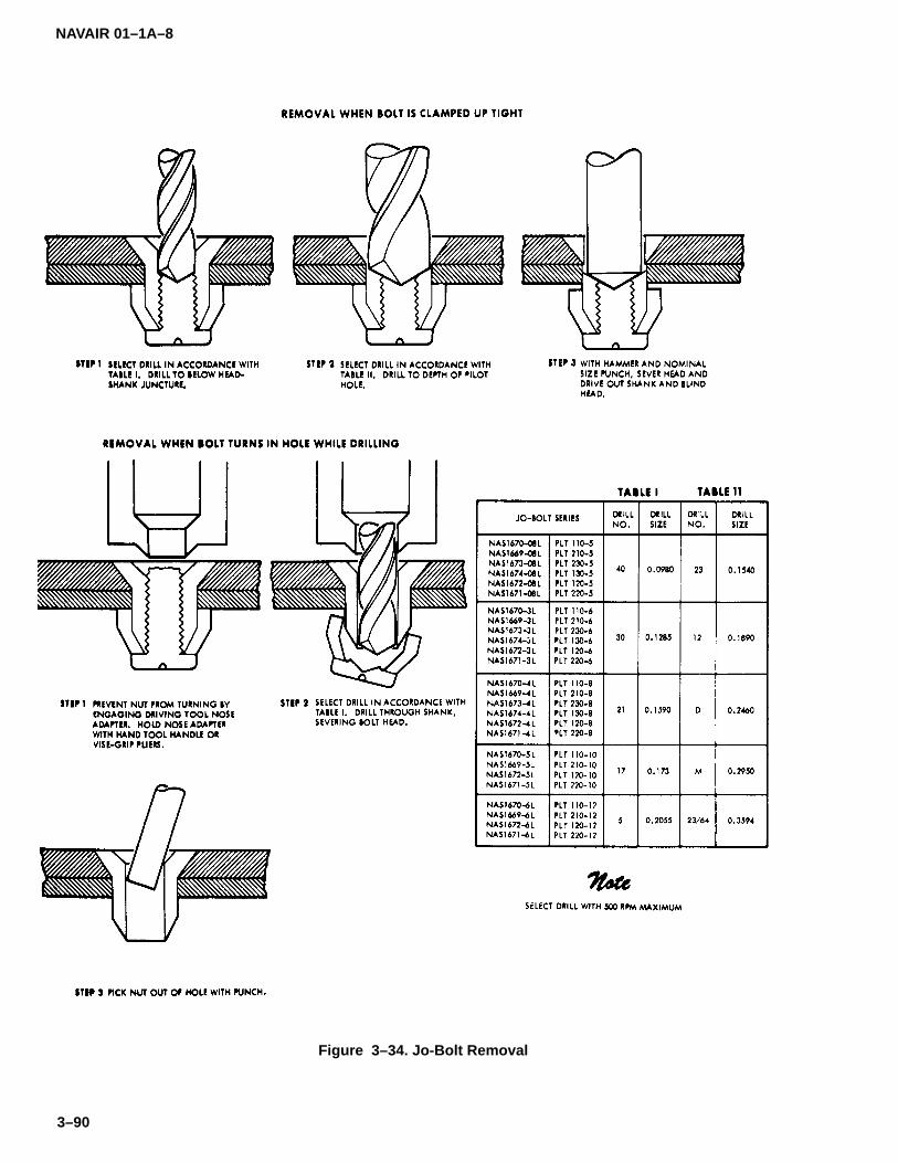
NAVAIR 01–1A–8
3–90
Figure 3–34. Jo-Bolt Removal

NAVAIR 01–1A–8
3–91
Table 3–61. Visu-Lok II Fasteners
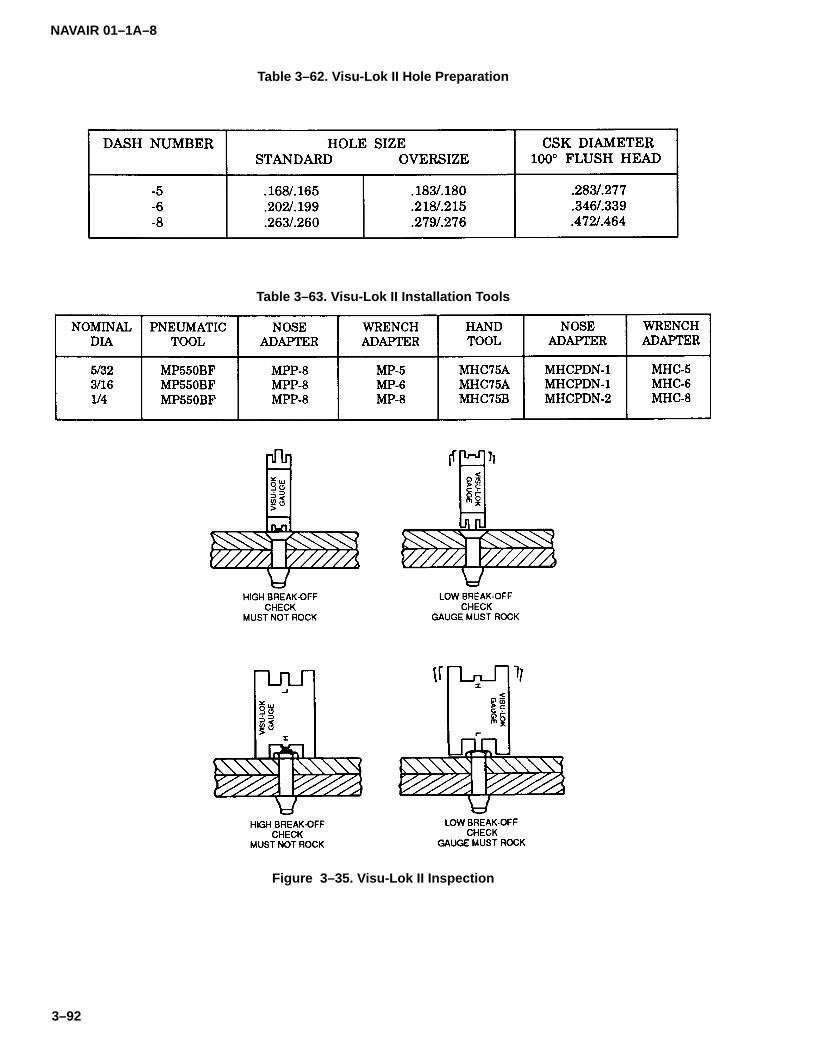
NAVAIR 01–1A–8
3–92
Table 3–62. Visu-Lok II Hole Preparation
Table 3–63. Visu-Lok II Installation Tools
Figure 3–35. Visu-Lok II Inspection

NAVAIR 01–1A–8
3–93
Table 3–64. Composi-Lok II Fasteners
NAVAIR 01–1A–8
3–94
3–122. COMPOSI-LOK II HOLE PREPARATION. Pre-pare holes for Composi-Lok II fasteners in accordancewith Table 3-65.
3–123. COMPOSI-LOK II INSTALLATION TOOLING.Pneumatic or hand tooling may be used to install Com-posi-Lok II fasteners. One nosepiece installs -5 through-8 fasteners and another nose-piece installs -9 through-12 fasteners.
3–124. INSTALLATION OF COMPOSI-LOK II FAS-TENERS. Install Composi-Lok II fasteners as follows:
a. Insert the proper fastener in the prepared holeand attach the driving tool.
b. Actuate the driving tool to tightly clamp up thesheets being joined.
c. The corebolt will fracture when the sleeve is ful-ly formed against the blind side of the structure.
3–125. INSPECTION OF COMPOSI-LOK II FASTEN-ERS. Inspect installed Composi-Lok II fasteners usingstem break-off gage per Figure 3-36.
3–126. REMOVAL OF COMPOSI-LOK II FASTENERS.Remove Composi-Lok II fasteners in accordance withparagraph 3-94.
3–127. RIVNUTS.
3–128. Rivnuts are internally threaded, counter-boredtubular fasteners manufactured from alloy steel, alumi-num alloy, or CRES. They are available in flathead andflush head styles (refer to Tables 3-66 and 3-67). Theblind end of the shank may be closed or open (see Fig-ure 3-37).
3–129. INSTALLATION TOOLS FOR RIVNUTS. Bothhand and power tools are available for installing rivnuts.A mandrel is threaded onto the rivnut before insertioninto the material. A special tool is used for forming key-ways for keyed rivnuts.
3–130. INSTALLATION OF RIVNUTS. Use the follow-ing procedure to install rivnuts:
a. Thread mandrel onto rivnut until anvil is flushagainst the head. If using a keyed rivnut, align the keywith the keyway.
b. Hold installation tool square to surface and ac-tuate. If using a hand tool, retract mandrel until solidresistance is felt.
c. Unthread mandrel and remove tool.
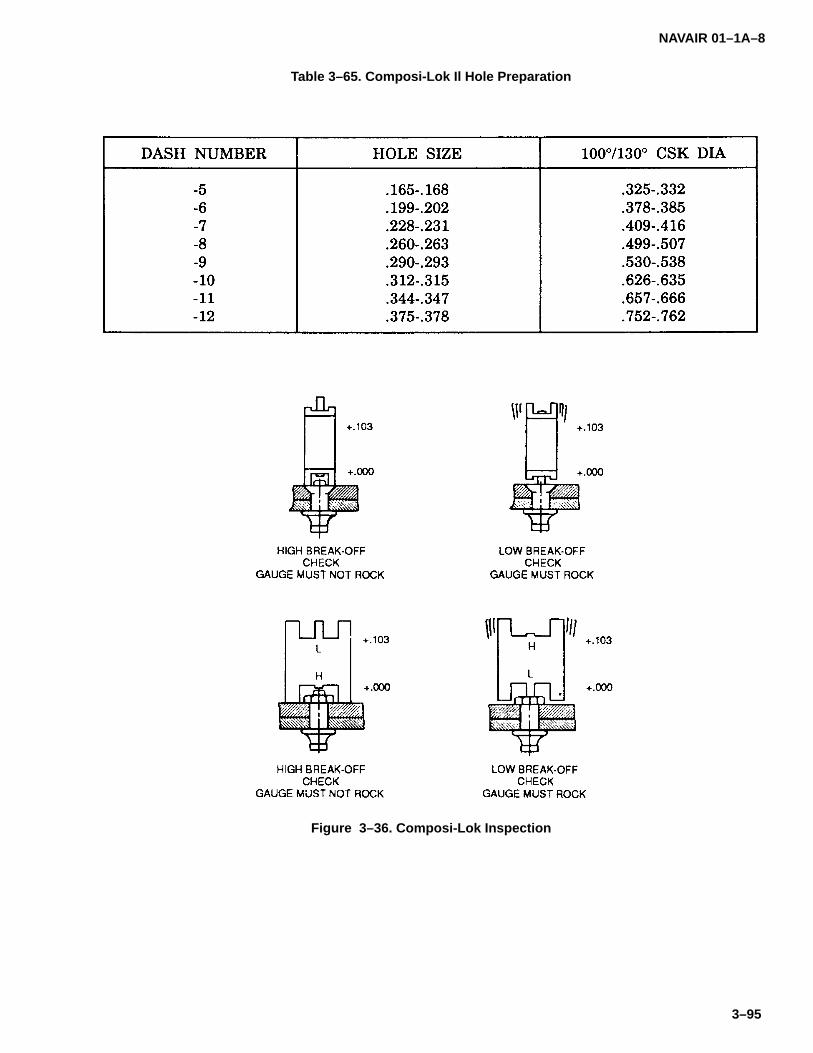
NAVAIR 01–1A–8
3–95
Table 3–65. Composi-Lok Il Hole Preparation
Figure 3–36. Composi-Lok Inspection

NAVAIR 01–1A–8
3–96
Table 3–66. NAS1329 Rivnut
Code:Diameter and grip range are tabulated on the following page.L after dash number indicates thread locking feature.A before dash number indicates aluminum alloy rivnut.S before dash number indicates carbon steel rivnut.H before dash number indicates alloy steel rivnut.C before dash number indicates CRES rivnut.– between dash numbers indicates open end keyless rivnut.K between dash numbers indicates open end keyed rivnut.B between dash numbers indicates closed end keyless rivnut.KB between dash numbers indicates closed end keyed rivnut.
Examples of Part Numbers:NAS1329A3K130 = aluminum alloy, open end keyed, .1900–32 internal thread rivnut with 0.080 to 0.130 griprange.NAS1329C6KB200 = CRES, closed end keyed, .3750–24 internal thread rivnut with 0.115 to 0.200 grip range.
Finish:Anodize aluminum alloy per MIL–A–8625, Type II.Cadmium–plate steel per QQ–P–416, Type II, Class 2.Passivate CRES per QQ–P–35, Type II.
Material:6053–T4 aluminum alloy per MIL–R–1150 (non–locking nuts only).Carbon Steel per QQ–W–405 (non–locking nuts only).Alloy Steel per QQ–W–405.CRES per QQ–W–423 (non–locking nuts only).
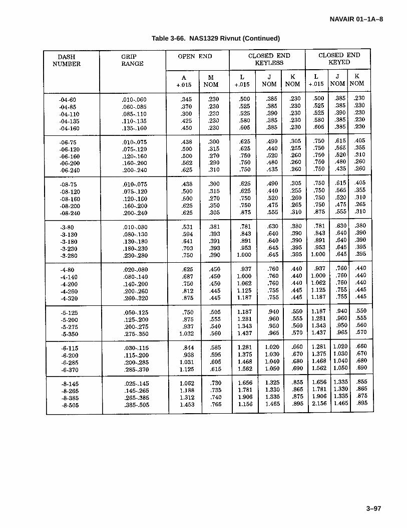
NAVAIR 01–1A–8
3–97
Table 3-66. NAS1329 Rivnut (Continued)
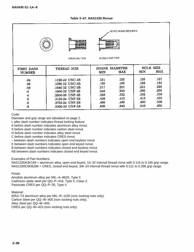
NAVAIR 01–1A–8
3–98
Table 3–67. NAS1330 Rivnut
Code:Diameter and grip range are tabulated on page 2.L after dash number indicates thread locking feature.A before dash number indicates aluminum alloy rivnut.S before dash number indicates carbon steel rivnut.H before dash number indicates alloy steel rivnut.C before dash number indicates CRES rivnut.– between dash numbers indicates open end keyless rivnut.K between dash numbers indicates open end keyed rivnut.B between dash numbers indicates closed end keyless rivnut.KB between dash numbers indicates closed end keyed rivnut.
Examples of Part Numbers:NAS1330A3K166 = aluminum alloy, open end keyed, 10–32 internal thread rivnut with 0.116 to 0.166 grip range.NAS1330C6KB296 = CRES, closed end keyed, 3/8–24 internal thread rivnut with 0.211 to 0.296 grip range.
Finish:Anodize aluminum alloy per MIL–A–8625, Type II.Cadmium–plate steel per QQ–P–416, Type II, Class 2.Passivate CRES per QQ–P–35, Type II.
Material:6053–T4 aluminum alloy per MIL–R–1150 (non–locking nuts only).Carbon Steel per QQ–W–405 (non–locking nuts only).Alloy Steel per QQ–W–405.CRES per QQ–W–423 (non–locking nuts only).

NAVAIR 01–1A–8
3–99
Table 3-67. NAS1330 RIVNUT (Continued)

NAVAIR 01–1A–8
3–100
Figure 3–37. Types of Rivnuts

NAVAIR 01–1A–8
4–1
SECTION IV
SCREWS
4–1. SCREWS.
4–2. Screws are externally threaded fasteners similarin design to bolts, except they usually have a lower ma-terial strength and a looser thread fit. However, severaltypes of structural screws differ from structural bolts onlyin head style. Brazier, round, and flush head screws areavailable with several types of recesses, each requiringa particular screwdriver for installation. Refer to SectionV for data regarding the different types of recesses andtooling. Several types of screws are described in the fol-lowing paragraphs:
4–3. PARTS OF A SCREW. Screws consist of the fol-lowing parts (see Figure 4-1)
a. Head. The portion into which the screwdriverfits.
b. Body. The portion from the bottom of the headto the beginning of the thread.
c. Threads. The helical portion of the screw.
d. Screw Length. For countersunk screws, thecombination of the head, body, and threads. For non-countersunk screws, the combination of the body andthreads.
Figure 4–1. Parts of a Screw

NAVAIR 01–1A–8
4–2
e. Grip Length. The distance from the underheadbearing surface to the beginning of the bevel just beforethe threads. On protruding head screws, the grip lengthis the same as the body. On flush head screws, the gripincludes the screw head.
f. Shank. The combination of the body andthreads.
4–4. HEAD MARKINGS. Screws and bolts are codedfor identification of physical properties per Table 4-1.Vendor trademarks are permissible on the screw head.
4–5. STRUCTURAL SCREWS.
4–6. Structural screws are used in primary aircraftstructural applications. They are manufactured fromhigh tensile and high shear strength materials. Structur-al screws are available in fillister, pan, and 100� flushhead styles (refer to Tables 4-2 through 4-6).
4–7. MACHINE SCREWS.
4–8. The following are types of machine screws:
a. Flush Head Machine Screws. Flush head ma-chine screws are used where a flush surface is desired.They are available in 82� and 100� flush head styleswith several recess types. They are manufactured fromcarbon steel, aluminum alloy, CRES, and brass (refer toTables 4-7 through 4-12).
b. Roundhead Machine Screws. Roundhead ma-chine screws are used in electrical applications. Theyare manufactured from carbon steel and brass (refer toTables 4-9 and 4-13).
c. Fillister Head Machine Screws. Fillister headmachine screws are drilled head screws designed foruse in general and light-duty applications. They aremanufactured from alloy steel and brass (refer to Tables4-14 through 4-16).
d. Socket Head Machine Screws. Socket headmachine screws are designed for use in applications re-quiring high strength and compactness. They aremanufactured from alloy steel or CRES (refer to Table4-17). Socket head machine screws are driven with in-ternal wrenches.
e. Pan Head Machine Screws. Pan head machinescrews are used in general application. where headheight is not restricted. They are available with cross-re-cessed heads and are manufactured from carbon steel,CRES, and aluminum alloy (refer to Tables 4-18 through4-21).
4–9. SELF-TAPPING SCREWS.
CAUTION
Self-tapping screws shall not be used toreplace standard screws, bolts, or rivets inthe original structure.
4–10. Self-tapping screws cut their own thread as theyare driven into the substrate. They are manufacturedwith a milled, off-center, thread-cutting slot which pro-duces an edge similar to a tap. The following are typesof self-tapping screws:
a. Self-Tapping Machine Screws. Self-tappingmachine screws are used primarily for attaching remov-able parts to castings. They are available in flatheadand roundhead styles (refer to Table 4-22).
b. Self-Tapping Sheet Metal Screws. Self-tappingsheet metal screws are used for temporary attachmentof sheet metal for riveting and for permanent assemblyof non-structural parts in blind applications (see Figure4-2). These screws are designed for use on steel andaluminum alloy sheets, but may also be used on plastic(refer to Tables 4-22 through 4-24).
4–11. DRIVE SCREWS.
4–12. Drive screws are self-tapping and are used innon-structural applications which do not require fasten-er removal, such as attachment of nameplates andsealing of drain holes. Drive screws are installed with ahammer rather than a driver (refer to Table 4-25).
4–13. WOOD SCREWS.
4–14. Wood screws are self-tapping screws designedfor use in wooden structures. They are available inroundhead and 82� flush head styles (refer to Table4-26).

NA
VAIR
01–1A–8
4–3/(4–4 blan
k)
Table 4–1. S
crew an
d B
olt M
arking
s (Sh
eet 1)

NA
VAIR
01–1A–8
4–5/(4–6 blan
k)
Table 4–1. S
crew an
d B
olt M
arking
s (Sh
eet 2)
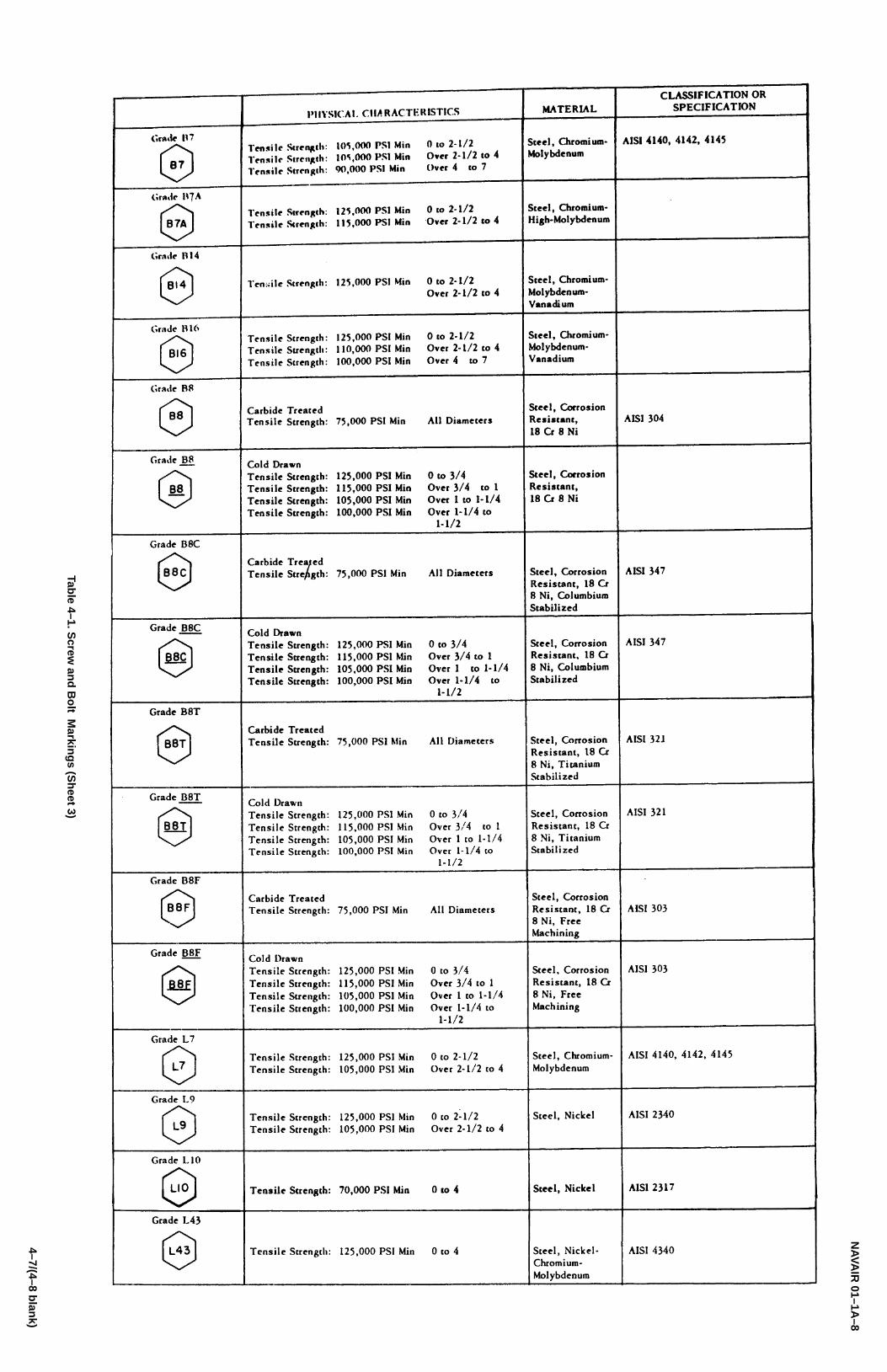
NA
VAIR
01–1A–8
4–7/(4–8 blan
k)
Table 4–1. S
crew an
d B
olt M
arking
s (Sh
eet 3)
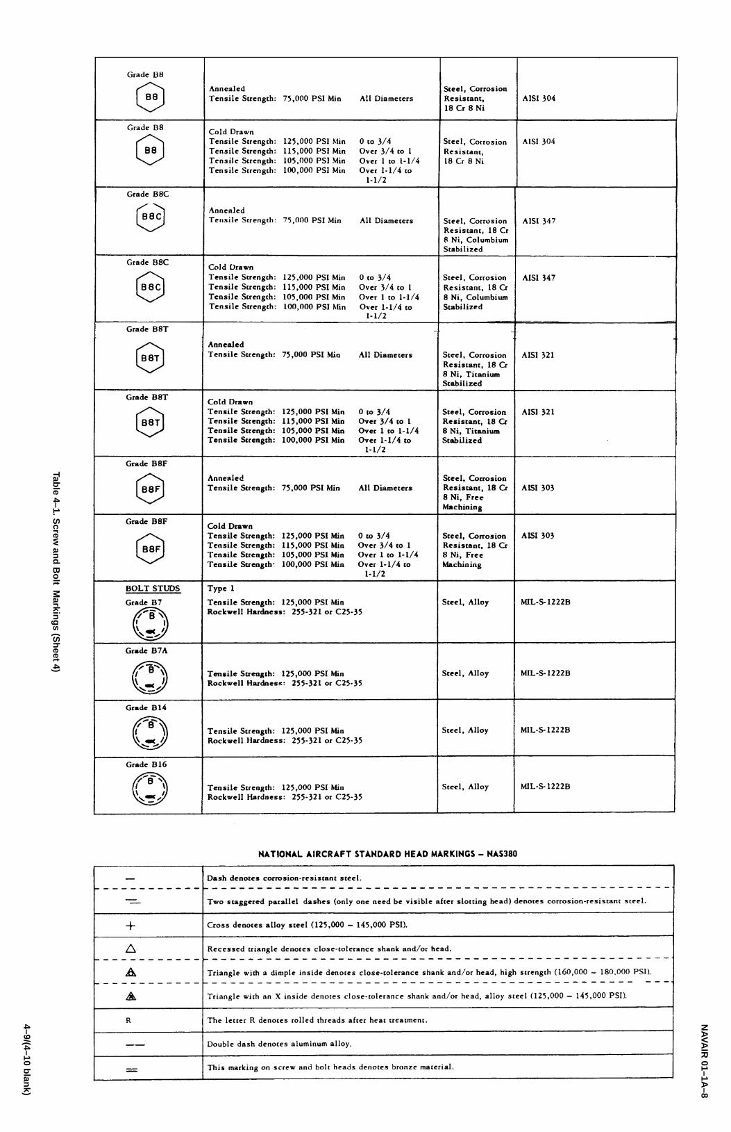
NA
VAIR
01–1A–8
4–9/(4–10 blan
k)
Table 4–1. S
crew an
d B
olt M
arking
s (Sh
eet 4)

NAVAIR 01–1A–8
4–11
Table 4–2. AN502 Fine Thread and AN503 Coarse Thread Fillister Head Structural Screws
Code:First dash number indicates screw size.Second dash number indicates screw length.
Example of Part Number:AN502–10–10 = 10–32 screws, 5/8–inch long.
Material:Alloy Steel per MIL–S–6050 or AMS6300.

NAVAIR 01–1A–8
4–12
Table 4–3. MS24694 Flathead Structural Screws
Code:Refer to specification for listing of dash numbers.
Material:Low Alloy Steel per MIL–S–6049 or MIL–S–6050.CRES per Fed. Std. 66, Steel No. 302, 303, 304, 305, or 316.Aluminum Alloy 2024 per QQ–A–430 or 2024–T4 per QQ–A–225.
Heat Treatment:Low alloy steel – 125–145 KSI tensile per MIL–H–6875.Aluminum alloy – 62 KSI tensile per MIL–H–6088.
Finish:Cadmium–plate per QQ–P–416, Type II, Class 3.Anodize per MIL–A–8625, Type I or II.Passivate per QQ–P–35.
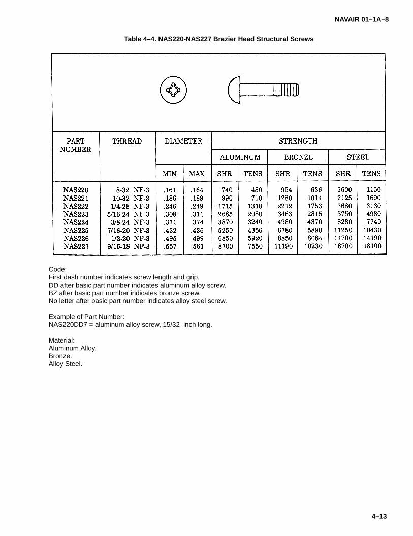
NAVAIR 01–1A–8
4–13
Table 4–4. NAS220-NAS227 Brazier Head Structural Screws
Code:First dash number indicates screw length and grip.DD after basic part number indicates aluminum alloy screw.BZ after basic part number indicates bronze screw.No letter after basic part number indicates alloy steel screw.
Example of Part Number:NAS220DD7 = aluminum alloy screw, 15/32–inch long.
Material:Aluminum Alloy.Bronze.Alloy Steel.

NAVAIR 01–1A–8
4–14
Table 4–5. NAS560 Flathead, High Temperature Structural Screw
Code:First dash number indicates screw size in1/16–inch.Second dash number indicates screw grip and length in 1/16–inch.C after basic part number indicates low strength CRES screw.H after basic part number indicates high temperature CRES screw.X after basic part number indicates high strength CRES screw.K after material code indicates cross recess.P after first dash number indicates cadmium–plated screw.
Example of Part Number:NAS560CK3P12 = low strength, cadmium–plated, cross–recessed screw, 3/16–inch diameter, 3/4–inch long.
Material:CRES per QQ–S–763.CRES per AMS5735.CRES per AMS5668.

NAVAIR 01–1A–8
4–15
Table 4–6. NAS583-NAS590 Flathead Structural Screws
Code:Dash number indicates grip in sixteenths of an inch.R before dash number indicates Torq–Set recess.Refer to specification for listing of dash numbers.
Examples of Part Numbers:NAS584–5 = .2500–28 steel screw, .312–inch grip, Hi–Torque recess.NAS584R5 = .2500–28 steel screw, .312–inch grip, Torq–Set recess.
Material:Alloy Steel4130 Alloy Steel per MIL–S–6758 for NAS586 or smaller.
Heat Treatment:160–180 KSI tensile strength per MIL–H–6875.
Finish:Cadmium–plate per QQ–P–416, Type II, Class 2.
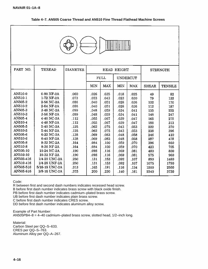
NAVAIR 01–1A–8
4–16
Table 4–7. AN505 Coarse Thread and AN510 Fine Thread Flathead Machine Screws
Code:R between first and second dash numbers indicates recessed head screw.B before first dash number indicates brass screw with black oxide finish.PB before first dash number indicates cadmium–plated brass screw.UB before first dash number indicates plain brass screw.C before first dash number indicates CRES screw.DD before first dash number indicates aluminum alloy screw.
Example of Part Number:AN505PB4–8 = 4–40 cadmium–plated brass screw, slotted head, 1/2–inch long.
Material:Carbon Steel per QQ–S–633.CRES per QQ–S–763.Aluminum Alloy per QQ–A–267.
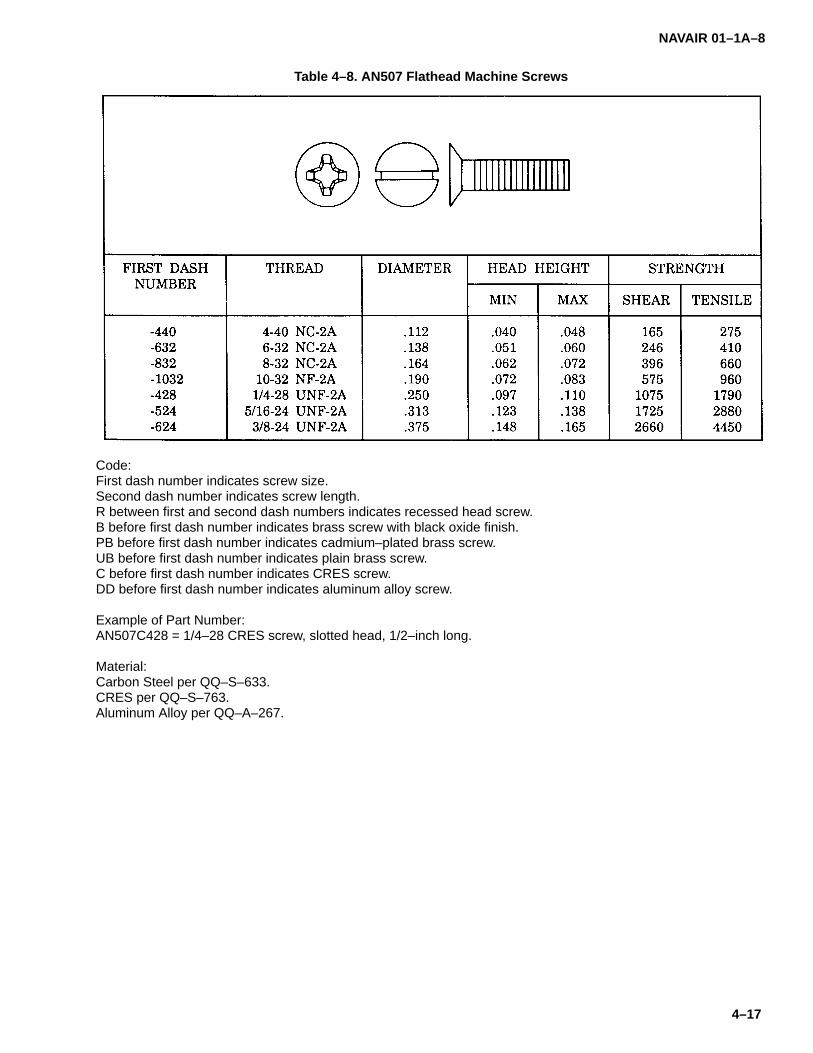
NAVAIR 01–1A–8
4–17
Table 4–8. AN507 Flathead Machine Screws
Code:First dash number indicates screw size.Second dash number indicates screw length.R between first and second dash numbers indicates recessed head screw.B before first dash number indicates brass screw with black oxide finish.PB before first dash number indicates cadmium–plated brass screw.UB before first dash number indicates plain brass screw.C before first dash number indicates CRES screw.DD before first dash number indicates aluminum alloy screw.
Example of Part Number:AN507C428 = 1/4–28 CRES screw, slotted head, 1/2–inch long.
Material:Carbon Steel per QQ–S–633.CRES per QQ–S–763.Aluminum Alloy per QQ–A–267.

NAVAIR 01–1A–8
4–18
Table 4–9. NAS200 Flathead and NAS202 Roundhead Machine Screws
Code:B before dash number indicates brass screw.C before dash number indicates cadmium–plated screw.
Example of Part Number:NAS200–632–18 = 6–32 steel screw, 1–1/8–inch long.
Material:1010 Steel.Brass per QQ–B–626.

NAVAIR 01–1A–8
4–19
Table 4–10. NAS514 Flathead Machine Screw
Code:First dash number indicates screw size.Second dash number indicates screw length.P before first dash number indicates Phillips recessed head.F before first dash number indicates Frearson recessed head.No letter before first dash number indicates slotted head.
Example of Part Number:NAS514P428–8 = 1/4–28 screw, Phillips recessed head, 1/2–inch long.
Material:Alloy Steel per MIL–S–6050 or AMS6300.

NAVAIR 01–1A–8
4–20
Table 4–11. NAS517 Flathead Machine Screw
Code:First dash number indicates screw size.Second dash number indicates screw length.
Example of Part Number:NAS517–3–3 = 10–32 screw, 3/16–inch long.
Material:Alloy Steel per AMS6300.

NAVAIR 01–1A–8
4–21
Table 4–12. NAS662 Flathead Machine Screw
Code:First dash number indicates screw diameter.Second dash number indicates screw length in 1/16–inch.B before first dash number indicates brass screw.C before first dash number indicates steel screw.R before second dash number indicates cross recess.
Example of Part Number:NAS662C3R4 = 3–48 CRES screw, cross recess, 1/4–inch long.
Material:Carbon Steel per QQ–S–633.CRES per QQ–S–763.Brass per QQ–B–626.

NAVAIR 01–1A–8
4–22
Table 4–13. AN508 Roundhead Machine Screw
Code:First dash number indicates screw diameter.Second dash number indicates screw length.
Example of Part Number:AN508–6–3 = 6–32 plated brass screw, 3/16–inch long.
Material:Brass per QQ–B–626.
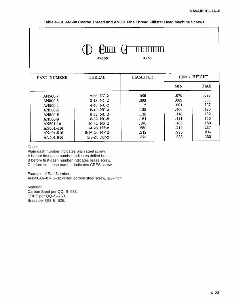
NAVAIR 01–1A–8
4–23
Table 4–14. AN500 Coarse Thread and AN501 Fine Thread Fillister Head Machine Screws
Code:Plain dash number indicates plain steel screw.A before first dash number indicates drilled head.B before first dash number indicates brass screw.C before first dash number indicates CRES screw.
Example of Part Number:AN500A6–8 = 6–32 drilled carbon steel screw, 1/2–inch
Material:Carbon Steel per QQ–S–633.CRES per QQ–S–763.Brass per QQ–B–626.

NAVAIR 01–1A–8
4–24
Table 4–15. Flat Fillister Head Machine Screws
Material:Alloy Steel per AMS5061.
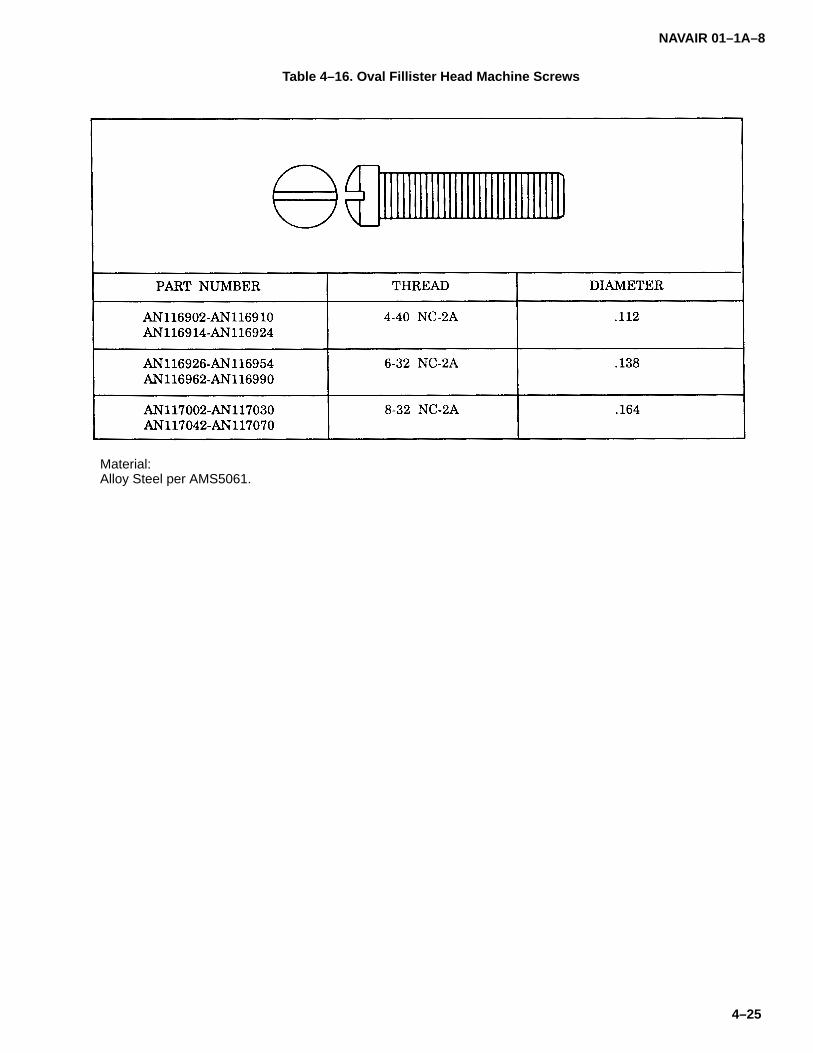
NAVAIR 01–1A–8
4–25
Table 4–16. Oval Fillister Head Machine Screws
Material:Alloy Steel per AMS5061.
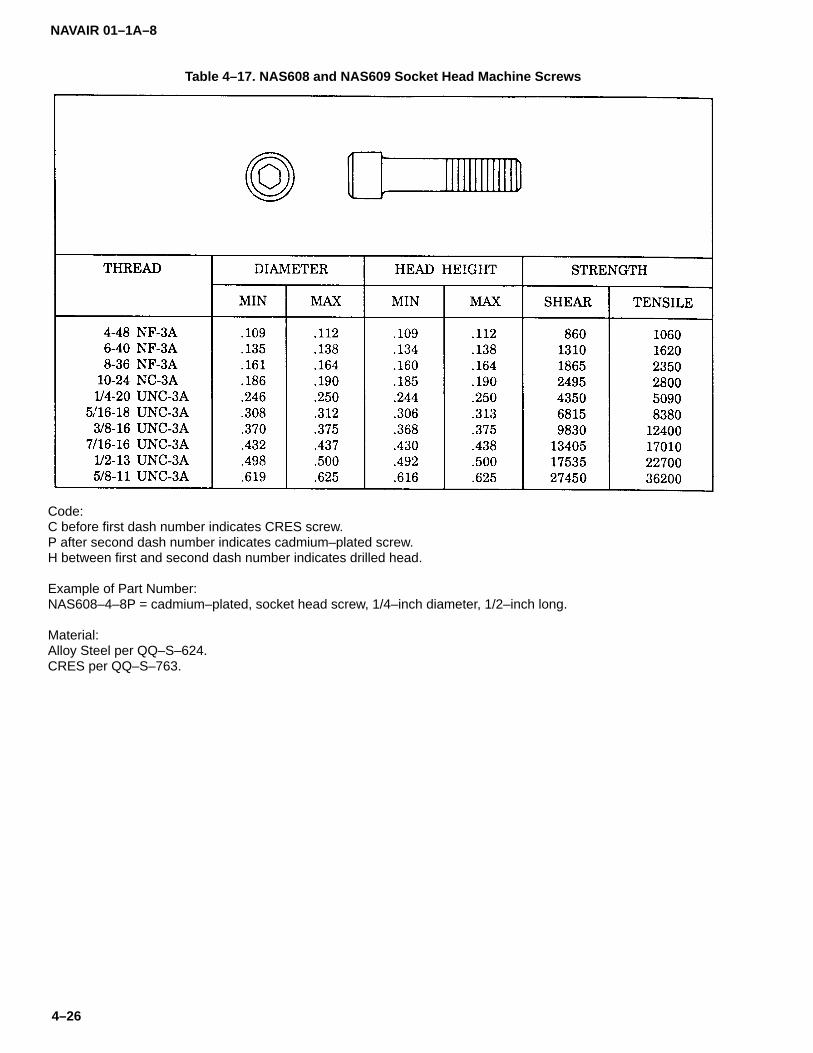
NAVAIR 01–1A–8
4–26
Table 4–17. NAS608 and NAS609 Socket Head Machine Screws
Code:C before first dash number indicates CRES screw.P after second dash number indicates cadmium–plated screw.H between first and second dash number indicates drilled head.
Example of Part Number:NAS608–4–8P = cadmium–plated, socket head screw, 1/4–inch diameter, 1/2–inch long.
Material:Alloy Steel per QQ–S–624.CRES per QQ–S–763.
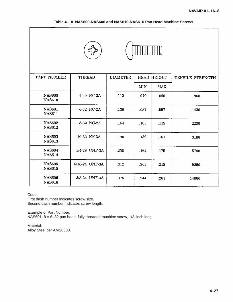
NAVAIR 01–1A–8
4–27
Table 4–18. NAS600-NAS606 and NAS610-NAS616 Pan Head Machine Screws
Code:First dash number indicates screw size.Second dash number indicates screw length.
Example of Part Number:NAS601–8 = 6–32 pan head, fully threaded machine screw, 1/2–inch long.
Material:Alloy Steel per AMS6300.

NAVAIR 01–1A–8
4–28
Table 4–19. NAS623 Pan Head, Short Thread Machine Screw
Code:First dash number indicates screw diameter.Second dash number indicates screw grip and length.W after second dash number indicates Type I plating.F before first dash number indicates Frearson recess.
Examples of Part Numbers:NAS623–4–10 = 1/4–inch diameter screw, .625 grip, Type II plating.NAS623F4–10W = 1/4–inch diameter screw, .625 grip, Type I plating.
Material:Alloy Steel per MIL–S–5000, MIL–S–5626, MIL–S–6049, or MIL–S–6098.
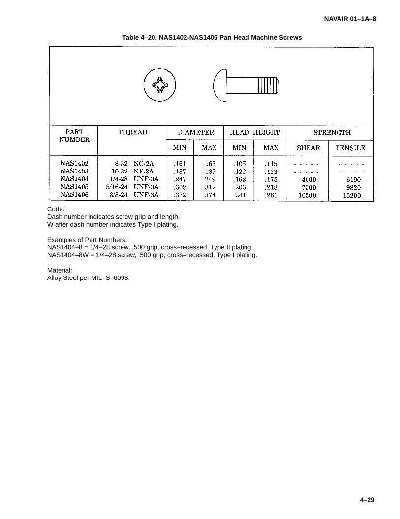
NAVAIR 01–1A–8
4–29
Table 4–20. NAS1402-NAS1406 Pan Head Machine Screws
Code:Dash number indicates screw grip and length.W after dash number indicates Type I plating.
Examples of Part Numbers:NAS1404–8 = 1/4–28 screw, .500 grip, cross–recessed, Type II plating.NAS1404–8W = 1/4–28 screw, .500 grip, cross–recessed, Type I plating.
Material:Alloy Steel per MIL–S–6098.

NAVAIR 01–1A–8
4–30
Table 4–21. MS35188-MS35203 and MS35204-MS35219 Flathead and Pan Head Machine Screws
Code:
Dash number indicates size and length of screw.
Material:
Carbon Steel per QQ–S–633.

NAVAIR 01–1A–8
4–31
Table 4–22. AN504 and AN530 Roundhead, Self-Tapping Sheet Metal Screws
Code:C before first dash number indicates CRES screw.R between first and second dash numbers indicates recessed head screw.
Example of Part Number:AN504–4–8 = 4–40 carbon steel, slotted head screw, 1–1/2–inch long.
Material:Carbon Steel per QQ–S–633.CRES per QQ–S–763.
Figure 4–2. Using Sheet Metal Screws

NAVAIR 01–1A–8
4–32
Table 4–23. AN531 Flathead, Self-Tapping Sheet Metal Screw
Code:C before first dash number indicates CRES screw.F between first and second dash number indicates fluted or slotted end.R between first and second dash numbers indicates recessed head screw.
Example of Part Number:AN531C6RF8 = 6–20 CRES, recessed head screw, fluted end, 1/2–inch long.
Material:Carbon Steel per MIL–S–6033.CRES per MIL–S–6033.

NAVAIR 01–1A–8
4–33
Table 4–24. NAS548 Flathead, Self-Tapping Sheet Metal Screw
Code:F after basic part number indicates Frearson recess.P after basic part number indicates Phillips recess.S after basic part number indicates slotted recess.C after dash number indicates chromium–plated screw.No letter after dash number indicates cadmium–plated screw.
Example of Part Number:NAS548F8–8C = 8–18 chromium–plated screw, Frearson recess, 1/2–inch long.
Material:Alloy Steel per MIL–S–18729.
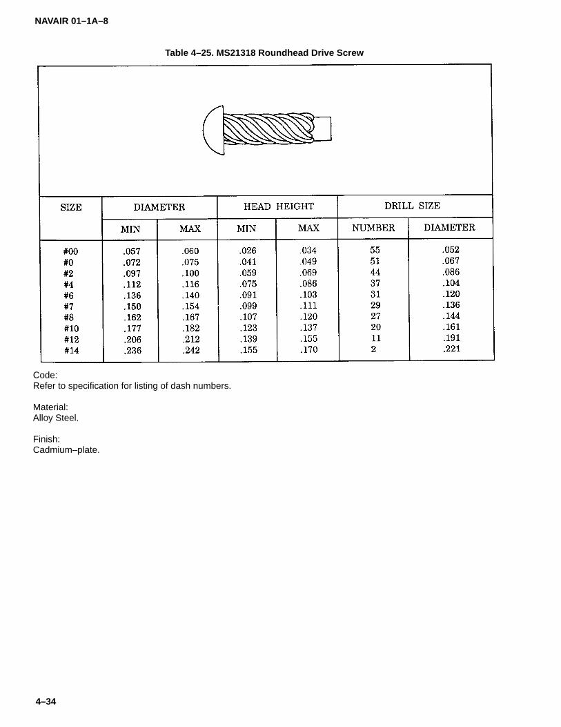
NAVAIR 01–1A–8
4–34
Table 4–25. MS21318 Roundhead Drive Screw
Code:Refer to specification for listing of dash numbers.
Material:Alloy Steel.
Finish:Cadmium–plate.

NAVAIR 01–1A–8
4–35
Table 4–26. MS35492 Flathead and MS35493 Roundhead Wood Screws
Code:Dash number indicates screw size
Material:Carbon Steel per QQ–S–633.Brass per QQ–B–626.
4–15. SETSCREWS.
4–16. Setscrews are used to position aircraft compo-nents, such as gears on a shaft. The following are typesof setscrews:
a. Hexagon and Fluted Socket Setscrews . Socketsetscrews are available in several point styles (refer toTable 4-27).
b. Self-Locking Setscrews. Self-locking set-screws are similar to hexagon setscrews, except theyhave a strip- or button-type locking element built into theshank. When the locking element is compressed by thethreads, the setscrew is locked in place (refer to Table4-28).
4–17. SCREW EXTRACTION.
4–18. Refer to NAVAIR 01-1A-1 Structural RepairManual for extraction of broken screws using a screwextractor.
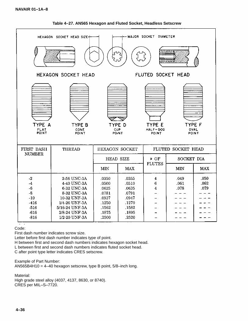
NAVAIR 01–1A–8
4–36
Table 4–27. AN565 Hexagon and Fluted Socket, Headless Setscrew
Code:First dash number indicates screw size.Letter before first dash number indicates type of point.H between first and second dash numbers indicates hexagon socket head.L between first and second dash numbers indicates fluted socket head.C after point type letter indicates CRES setscrew.
Example of Part Number:AN565B4H10 = 4–40 hexagon setscrew, type B point, 5/8–inch long.
Material:High grade steel alloy (4037, 4137, 8630, or 8740).CRES per MIL–S–7720.

NAVAIR 01–1A–8
4–37/(4–38 blank)
Table 4–28. NAS1081 Self-locking Setscrew
Code:First dash number indicates screw size.Second dash number indicates screw length.Dash before first dash number indicates cadmium–plated steel setscrew.C before first dash number indicates CRES setscrew.A between first and second dash numbers indicates flat point.B between first and second dash numbers indicates cone point.L after second dash number indicates strip–type locking element.N after second dash number indicates button–type locking element.
Example of Part Number:NAS1081–4A12 = 1/4–28 cadmium–plated steel, self–locking setscrew, flat point, 3/4–inch long.
Material:Chrome–molybdenum steel per MILS–6758.CRES per MIL–S–7720.


NAVAIR 01–1A–8
5–1
SECTION V
BOLTS
5–1. BOLTS.
5–2. Hex, internal wrenching, and close-tolerancetype bolts are used in aircraft structural applications.
5–3. GRIP LENGTH. The grip length of a bolt is thedistance from the underhead bearing surface to the firstthread. The grip is the total thickness of material joinedby the bolt. Ideally, the grip length should be a few thou-sandths of an inch less than the actual grip to avoidbottoming the nut. As a rule of thumb, a minimum of twoand a maximum of four complete threads, including thechamfered end, shall protrude through the nut. Bolts ofslightly greater grip length may be used if a washer isplaced under the nut or bolt head. Shims may be usedunder plate nuts to provide the proper thread protrusion.
5–4. BOLT IDENTIFICATION. Several manufactur-ers produce bolts having dimensions and/or physicalproperties differing from those of standard aircraft bolts.These bolts are identified by the letter S stamped on thehead. Refer to Table 4-1 of Section IV for standard bolthead markings.
5–5. BOLT HARDNESS. Bolt hardness may be de-termined using a Rockwell, BrineIl, or Vickershardness-testing machine. Prepare bolts for testing byfiling, grinding, and/or polishing to remove plating, de-carburized material, scratches, and other variations thatmay affect the reading. Discard all tested bolts.
5–6. BOLT HOLE PREPARATION. Except for light-drive fit applications (refer to paragraph 5-7), drill boltholes using the first drill size larger than the nominal boltdiameter for bolts up to 1/2-inch in diameter (refer toTable 2-1 of Section II for drill sizes). Use equal size drillbits for bolts of diameter greater than 1/2-inch. Boltholes shall not be oversize or elongated, or the bolt willnot carry shear load until the structure has yielded (seeFigure 5-1). Drill bolt holes square to the surface to pro-vide full bearing surface. Consult applicable aircraftTMS or CFA for repair of oversize and elongated holes.
Figure 5–1. Bolted Joint with Oversize Hole
CAUTION
Do not substitute a standard bolt for anoversize bolt or a loose fit will result.Check hole size with a micrometer if animproper fit is evident.
5–7. LIGHT-DRIVE FIT. A light-drive fit is defined asan interference fit of 0.0006-inch for 5/8-inch diameterbolts or a proportional amount of interference for othersize bolts. Use care when drilling light-drive fit holes toavoid elliptical, eccentric, or otherwise untrue holes.Use the following procedure to prepare a light-drive fit:
a. Precisely measure with a micrometer the diam-eter of several bolts and sort them into large, medium,and small groups.
b. Pilot drill initial hole(s) 1/32-inch undersize(1/8-inch undersize for 3/4-inch or larger bolts). Drill to1/64-inch undersize.
c. Ream holes to accept the small bolts and checkthe fit.
d. If the hole is too small, ream to a slightly largerhole size.
e. If these holes are too large, use the medium orlarge group of bolts as applicable.

NAVAIR 01–1A–8
5–2
5–8. WET INSTALLATION OF FASTENERS. Somethreaded fasteners require sealing during or after instal-lation with MIL-S-81733 Type I sealant (see Figure 5-2).To seal during installation, apply sealant to the hole ordip fastener in sealant and install while sealant is stillwet. For non-permanent structure, coat the bottom sur-face of the fastener head only. If sealant is applied to theshank, threads, or hole, fastener removal will be difficultwithout damaging the structure. To seal after installa-tion, coat the head of the fastener.
NOTEFor fuel cell applications where the fas-tener will be in contact with jet fuel, sealwith MIL-S-8802 sealant only. Do not useMIL-S-81733 sealant in fuel cell applica-tions.
5–9. AIRCRAFT MACHINE BOLTS.
5–10. Aircraft machine bolts are designed for use inapplications under tension and shear loads and areavailable with drilled heads or shanks for securing pur-poses. The following are types of aircraft machine bolts:
a. Standard Aircraft Machine Bolts. AN3-AN20and MS20073-MS20074 standard aircraft machinebolts are manufactured from alloy steel, CRES, or alu-minum alloy (refer to Tables 5-1 and 5-2). AN3-AN20and MS20073-MS20074 series bolts are interchange-able with respect to tensile and shear strength, however,thread length and head height may prevent direct inter-change ability. To prevent overstressing, 3/16-inchmachine bolts shall not be used in primary structures.
Figure 5–2. Typical Methods of Sealing Fasteners

NAVAIR 01–1A–8
5–3
b. Non-magnetic CRES Machine Bolts. NAS501bolts are similar to standard aircraft machine bolts, ex-cept they are manufactured from a different alloy (referto Table 5-3). NAS1003-NAS1020 bolts differ fromNAS501 bolts only in heat-resistance properties (referto Table 5-4).
c. Engine Machine Bolts. These bolts aremanufactured from alloy steel or CRES and are de-signed specifically for use in aircraft engines. All aresimilar except for the number and location of drilledholes (refer to Tables 5-5 and 5-6).AN101001-AN101900 and AN104601-AN105500 se-ries bolts are undrilled; AN101901-AN102800 andAN105501-AN106400 series bolts have drilled shanks;AN102801-AN103700 and AN106401-AN107300 se-ries bolts have one hole drilled in the head;AN107301-AN108200 series bolts have six holes drilledin the head.
5–11. CLOSE-TOLERANCE MACHINE BOLTS.Close-tolerance machine bolts provide an interferencefit and are designed for use in applications where thebolted joint is subject to severe load reversals and/orvibration. Close-tolerance bolts are available in hex and100� flush head styles. Flush head bolts are availablewith slotted, phillips, or socket recesses. Steel and alu-minum close-tolerance bolts may be identified by atriangle on top of the head. Titanium close-tolerancebolts may be identified by the part number and manufac-turer’s symbol on the head. Standard hex head bolts areotherwise identical and may be used in the same ap-plications as steel close-tolerance bolts if a light-drive fitis used in accordance with paragraph 5-7. The followingare types of close-tolerance bolts:
CAUTION
Ensure a tight fit is obtained when usingclose-tolerance bolts in critical applica-tions (landing gears, control systems,etc.).
a. Close Tolerance Machine Bolts. AN173-AN186hex head close-tolerance bolts are manufactured fromalloy steel, aluminum alloy, or CRES (refer to Table 5-7).
b. Close-tolerance Titanium Machine Bolts.NAS653-NAS658 are hex head close-tolerance, tita-nium alloy bolts; NAS663-NAS668 are 100� flush head,close-tolerance, titanium alloy bolts; andNAS673-NAS678 are drilled head, close-tolerance, tita-nium alloy bolts (refer to Table 5-8).
c. Close-tolerance, High Strength Machine Bolts.NAS333-NAS340 are 100� flush head, close-tolerancebolts; NAS6603-NAS6620 are hex head, close-toler-ance bolts; NAS6203-NAS6220 are hex head,close-tolerance, short thread bolts; NAS1202-NAS1207are 100� flush head, close-tolerance, short thread bolts;and NAS1503-NAS1510 are 100� flush head, close-tol-erance, short thread bolts (refer to Tables 5-9 through5-11). All these bolts are 160 to 180 KSI heat treated.
CAUTION
When using self-locking nuts on shortthread bolts, a minimum of two threadpitches shall extend through the nut andthere shall be two thread pitches betweenthe nut and the thread run-out on the boltshank.
5–12. INTERNAL WRENCHING BOLTS. Internalwrenching bolts are designed for use in tension applica-tions. Standard hex head bolts shall not be substitutedfor internal wrenching bolts due to differences in heat-treatment. The following are types of internal wrenchingbolts:
a. Socket Head Bolts. NAS144-NAS158 andNAS172-NAS176 series bolts are high strength steelsocket head bolts heat treated to 160 to 180 KSI tensilestrength (refer to Table 5-12).
b. Drilled Socket Head Bolts. MS20004-MS20024and AN148551-AN149350 bolts are six hole, drilledsocket head bolts (refer to Tables 5-13 and 5-14).NAS144-NAS158 and NAS172-NAS176 bolts may beused interchangeably with MS20004-MS20024 bolts.

NAVAIR 01–1A–8
5–4
Table 5–1. AN3-AN20 Standard Aircraft Machine Bolt
Code:Dash number indicates grip and length.C before dash number indicates CRES bolt.DD before dash number indicates aluminum alloy bolt.A after dash number indicates undrilled bolt.H before dash number indicates drilled head and shank.H before dash number and A after dash number indicates drilled head only.
Examples of Part Numbers:AN6–10 = 7/16–inch. CRES bolt, 3/8–24 thread, 1–5/64–inch long, drilled shank only.AN6DDH10A = 7/16–inch aluminum alloy bolt, 3/8–24 thread, 1–5/64–inch long, drilled head only.
Material:Alloy Steel.CRES.Aluminum Alloy.
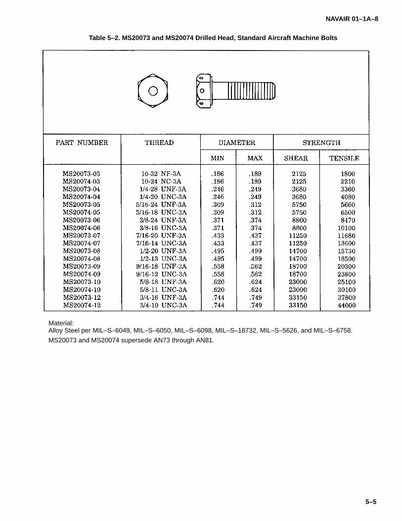
NAVAIR 01–1A–8
5–5
Table 5–2. MS20073 and MS20074 Drilled Head, Standard Aircraft Machine Bolts
Material:Alloy Steel per MIL–S–6049, MIL–S–6050, MIL–S–6098, MIL–S–18732, MIL–S–5626, and MIL–S–6758.
MS20073 and MS20074 supersede AN73 through AN81.
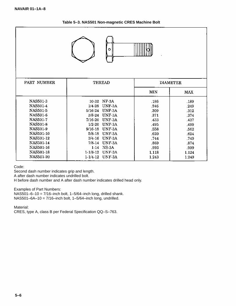
NAVAIR 01–1A–8
5–6
Table 5–3. NAS501 Non-magnetic CRES Machine Bolt
Code:Second dash number indicates grip and length.A after dash number indicates undrilled bolt.H before dash number and A after dash number indicates drilled head only.
Examples of Part Numbers:NAS501–6–10 = 7/16–inch bolt, 1–5/64–inch long, drilled shank.NAS501–6A–10 = 7/16–inch bolt, 1–5/64–inch long, undrilled.
Material:CRES, type A, class B per Federal Specification QQ–S–763.

NAVAIR 01–1A–8
5–7
Table 5–4. NAS1003-NAS1020 Non-magnetic Heat-Resistant Machine Bolt
Code:Dash number indicates grip in 1/16–inch.A after dash number indicates undrilled bolt.H after dash number indicates drilled head only.No letter indicates drilled shank only.
Example of Part Number:NAS1003–8 = 3/16–inch bolt, 1/2–inch long, drilled shank only.
Material:CRES, A286 per AMS5735, except uts 140 KSI at room temperature.

NAVAIR 01–1A–8
5–8
Table 5–5. AN Machine Bolts
Code:AN101001–AN101900 bolts are undrilled bolts.AN101901–AN102800 bolts are drilled shank bolts.AN102801–AN103700 bolts are one hole, drilled head bolts.AN103701–AN104600 bolts are six hole, drilled head bolts.
Material:Alloy Steel per AMS6322.
Hardness:Rockwell C26–C32.
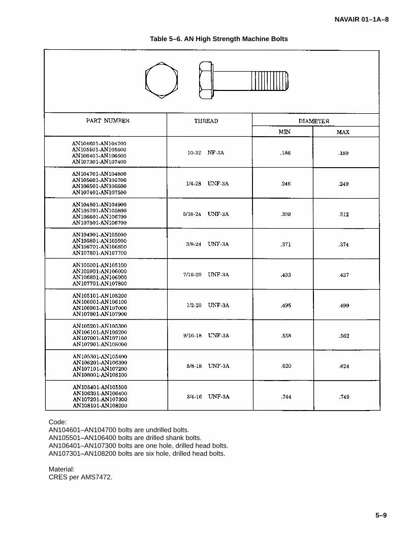
NAVAIR 01–1A–8
5–9
Table 5–6. AN High Strength Machine Bolts
Code:AN104601–AN104700 bolts are undrilled bolts.AN105501–AN106400 bolts are drilled shank bolts.AN106401–AN107300 bolts are one hole, drilled head bolts.AN107301–AN108200 bolts are six hole, drilled head bolts.
Material:CRES per AMS7472.
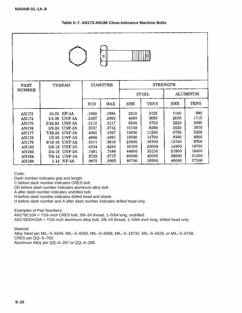
NAVAIR 01–1A–8
5–10
Table 5–7. AN173-AN186 Close-tolerance Machine Bolts
Code:Dash number indicates grip and length.C before dash number indicates CRES bolt.DD before dash number indicates aluminum alloy bolt.A after dash number indicates undrilled bolt.H before dash number indicates drilled head and shank.H before dash number and A after dash number indicates drilled head only.
Examples of Part Numbers:AN176C10A = 7/16–inch CRES bolt, 3/8–24 thread, 1–5/64 long, undrilled.AN176DDH10A = 7/16–inch aluminum alloy bolt, 3/8–24 thread, 1–5/64–inch long, drilled head only.
Material:Alloy Steel per MIL–S–6049, MIL–S–6050, MIL–S–6098, MIL–S–18732, MIL–S–5626, or MIL–S–6758.CRES per QQ–S–763.Aluminum Alloy per QQ–A–267 or QQ–A–268.
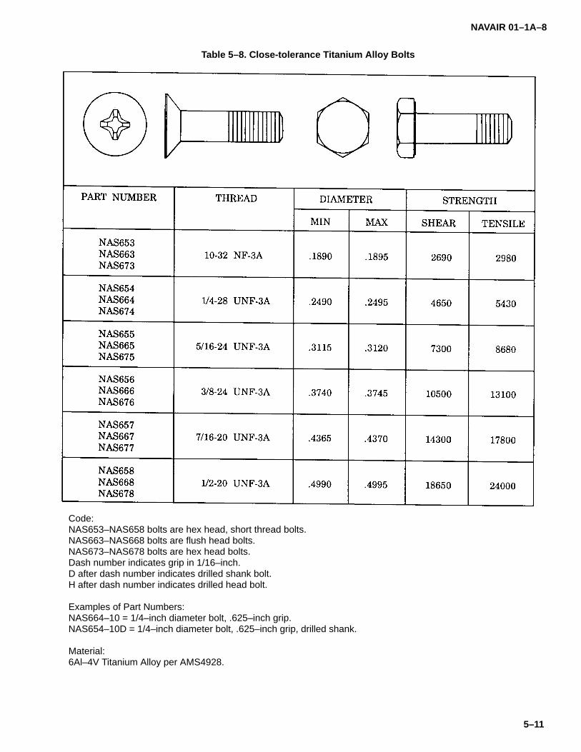
NAVAIR 01–1A–8
5–11
Table 5–8. Close-tolerance Titanium Alloy Bolts
Code:NAS653–NAS658 bolts are hex head, short thread bolts.NAS663–NAS668 bolts are flush head bolts.NAS673–NAS678 bolts are hex head bolts.Dash number indicates grip in 1/16–inch.D after dash number indicates drilled shank bolt.H after dash number indicates drilled head bolt.
Examples of Part Numbers:NAS664–10 = 1/4–inch diameter bolt, .625–inch grip.NAS654–10D = 1/4–inch diameter bolt, .625–inch grip, drilled shank.
Material:6Al–4V Titanium Alloy per AMS4928.
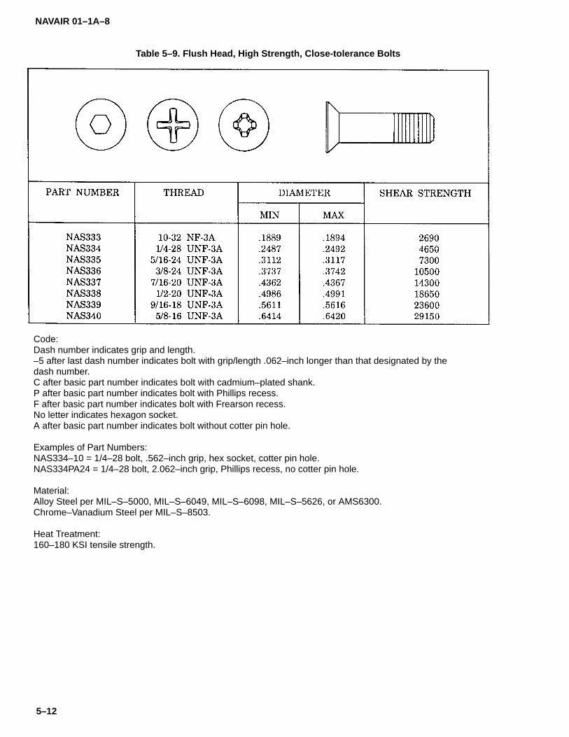
NAVAIR 01–1A–8
5–12
Table 5–9. Flush Head, High Strength, Close-tolerance Bolts
Code:Dash number indicates grip and length.–5 after last dash number indicates bolt with grip/length .062–inch longer than that designated by thedash number.C after basic part number indicates bolt with cadmium–plated shank.P after basic part number indicates bolt with Phillips recess.F after basic part number indicates bolt with Frearson recess.No letter indicates hexagon socket.A after basic part number indicates bolt without cotter pin hole.
Examples of Part Numbers:NAS334–10 = 1/4–28 bolt, .562–inch grip, hex socket, cotter pin hole.NAS334PA24 = 1/4–28 bolt, 2.062–inch grip, Phillips recess, no cotter pin hole.
Material:Alloy Steel per MIL–S–5000, MIL–S–6049, MIL–S–6098, MIL–S–5626, or AMS6300.Chrome–Vanadium Steel per MIL–S–8503.
Heat Treatment:160–180 KSI tensile strength.

NAVAIR 01–1A–8
5–13
Table 5–10. Close-tolerance, 160 KSI Bolts
Code:Dash number indicates grip and length.D after dash number indicates drilled shank bolt.H after dash number indicates drilled head bolt.– after basic part number indicates cadmium–plated bolt.C after basic part number indicates chromium–plated bolt.
Examples of Part Numbers:NAS6604D10 = 1/4–28, .625 grip, drilled shank, cadmium–plated bolt.NAS6604C10 = 1/4–28, .625 grip, undrilled, chromium–plated bolt.
Material:Alloy Steel 4340 per MIL–S–5000.Alloy Steel 8740 per MIL–S–6049 or AMS6322.
Heat Treatment:160–180 KSI per MIL–H–6875.
Finish:Cadmium–plate per QQ–P–416, Type II, Class 2.Chromium–plated per QQ–C–320, Class 2, shank only.
Use NAS6603–NAS6620 in place of NAS1303–NAS1320.

NAVAIR 01–1A–8
5–14
Table 5–11. NA56203 Through NAS 6220 Hex Head, Close-tolerance, 160,000 PSI, Short Thread Bolts;NAS1202 Through NAS1207, 100-Degree, Close-tolerance Head and Shank, 160,000 PSI, Short Thread
Bolts; and NAS1503 Through NAS1510, 100-Degree, Close-tolerance Head and Shank, 160,000 PSI, ShortThread Bolts
Code.Dash number indicates grip in sixteenths and is used to designate length also.D after dash number designates drilled shank (applicable to NAS6203 through NAS6220 only).F in place of dash designates Frearson recess (applicable to NAS1202 through NAS1207 only).H after dash number designates drilled head (applicable to NAS6203 through NAS6220 only).
Example of Part Number:NAS6204–10D= bolt, hex head, 1/4–inch diameter, .625 grip, drilled shank.NAS1204–8= bolt, 1/4–inch diameter, .500 grip, Phillips recess.NAS1204F8= bolt, 1/4–inch diameter, .500 grip, Frearson recess.NAS1504–8= bolt, 1/4–inch diameter, .500 grip, hi–torque slot.
Material:Steel, Military Specifications MIL–S–5000, MIL–S–6049, and MIL–S–6098.Steel, Military Specification MIL–S–5626.Chrome–vanadium steel Military Specification MIL–S–8503.Steel, Military Specification MIL–S–8695.
Heat Treatment:160,000 to 180,000 PSI, Military Specification MIL–H–6875.
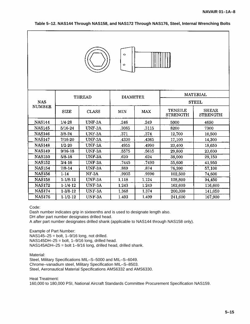
NAVAIR 01–1A–8
5–15
Table 5–12. NAS144 Through NAS158, and NAS172 Through NAS176, Steel, Internal Wrenching Bolts
Code:Dash number indicates grip in sixteenths and is used to designate length also.DH after part number designates drilled head.A after part number designates drilled shank (applicable to NAS144 through NAS158 only).
Example of Part Number:NAS145–25 = bolt, 1–9/16 long, not drilled.NAS145DH–25 = bolt, 1–9/16 long, drilled head.NAS145ADH–25 = bolt 1–9/16 long, drilled head, drilled shank.
Material:Steel, Military Specifications MIL–S–5000 and MIL–S–6049.Chrome–vanadium steel, Military Specification MIL–S–8503.Steel, Aeronautical Material Specifications AMS6332 and AMS6330.
Heat Treatment:160,000 to 180,000 PSI, National Aircraft Standards Committee Procurement Specification NAS159.
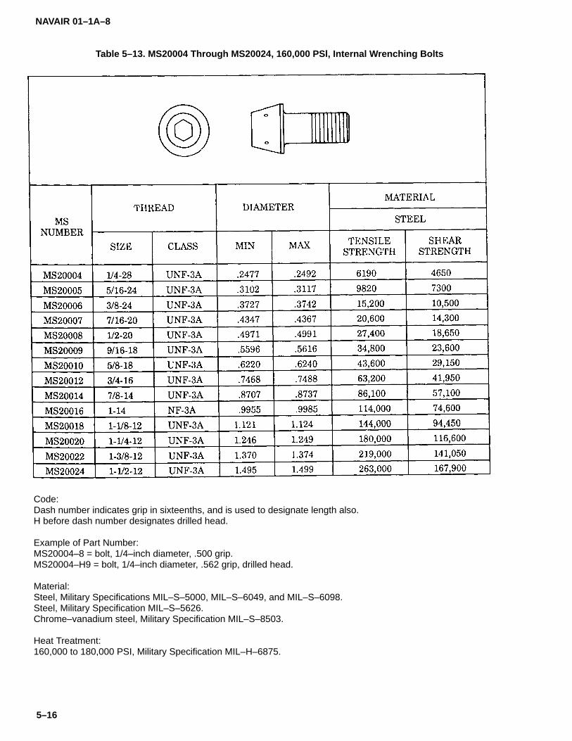
NAVAIR 01–1A–8
5–16
Table 5–13. MS20004 Through MS20024, 160,000 PSl, Internal Wrenching Bolts
Code:Dash number indicates grip in sixteenths, and is used to designate length also.H before dash number designates drilled head.
Example of Part Number:MS20004–8 = bolt, 1/4–inch diameter, .500 grip.MS20004–H9 = bolt, 1/4–inch diameter, .562 grip, drilled head.
Material:Steel, Military Specifications MIL–S–5000, MIL–S–6049, and MIL–S–6098.Steel, Military Specification MIL–S–5626.Chrome–vanadium steel, Military Specification MIL–S–8503.
Heat Treatment:160,000 to 180,000 PSI, Military Specification MIL–H–6875.

NAVAIR 01–1A–8
5–17
Table 5–14. AN148551 Through AN149350, Six Hole, Drilled Socket Head Bolts
Example of Part Number:AN148974 = bolt, 7/16–20, drilled socket head (six holes), length 1.625, grip .500.
Material:Steel, Aeronautical Material Specification AMS6322.
Hardness:Rockwell C32–C36.

NAVAIR 01–1A–8
5–18
5–13. 12-POINT EXTERNAL WRENCHING BOLTS.12-point bolts are used primarily in high tensile strengthapplications. A hole is formed in the bolt head to reduceweight. Standard bolts shall not be substituted for thesebolts. The following are types of 12-point externalwrenching bolts:
a. High Strength 12-Point Bolts.NAS624-NAS644 12-point external wrenching bolts areheat treated to 180 ESI tensile strength minimum (referto Table 5-15).
b. 12-Point Machine Bolts. MS9033 - MS9039bolts are 12-point heat-resistant machine bolts;MS9088-MS9094 bolts are 12-point drilled head, cad-mium-plated machine bolts (refer to Tables 5-16 and5-17). These are similar to NAS624-NAS644 bolts, ex-cept for material differences and larger shanktolerances.
5–14. CLOSE-TOLERANCE SHEAR BOLTS.NAS464 close-tolerance shear bolts are high strengthbolts with drilled shanks (refer to Table 5-18). They aredesigned for use in shear applications only.
5–15. FULL THREADED BOLTS. NAS563-NAS572full threaded bolts are manufactured from alloy steel andare heat-treated to 160 to 180 KSI tensile strength (referto Table 5-19).
5–16. CLEVIS BOLTS. AN21-AN36 clevis bolts aredesigned for use in shear applications only. The bolthead is round with a slotted recess (refer to Table 5-20).They may be used as mechanical pins in control sys-tems.
5–17. EYEBOLTS. AN42-AN49 eyebolts are used tocarry external tension loads for the attachment of de-vices such as turnbuckle forks or cable shackles (referto Table 5-21).
5–18. SUBSTITUTION AND INTERCHANGEABIL-ITY OF STANDARD AIRCRAFT BOLTS.
CAUTION
Do not substitute shear bolts for tensionbolts.
5–19. Refer to Tables 5-22 and 5-23 for substitutionand interchangeability of protruding and flush head bolts
and screws. Although one bolt may be substituted foranother, the opposite is not always true. For example,a 1200�F bolt may replace a 450�F bolt, but a 450�Fbolt shall not replace a 1200�F bolt. Although unpracti-cal from a cost standpoint to replace a low temperaturebolt with a high temperature bolt, if no other replace-ments are available, this may be done. Close-tolerancebolts shall be replaced by standard tolerance bolts on atemporary basis only.
5–20. SELF-LOCKING BOLTS.
CAUTION
Self-locking bolts with nylon locking ele-ments shall not be used in applicationssubject to temperatures exceeding250�F.
5–21. Self-locking bolts are manufactured to stan-dards such as MS20004-MS20024, NAS333-NAS340,and NAS1303-NAS1320, except they incorporate a ny-lon pellet or strip type locking device forced into a slot inthe threads per MIL-F-18240 (refer to Table 5-24). Thenylon pellet or strip is compressed as the bolt is threadedinto a tapped hole. Self-locking bolts should not be re-used.
5–22. INTERNAL WRENCHING FASTENERS.
5–23. Figure 5-3 illustrates several internal wrenchingrecesses.
NOTEDiscard drivers when they becomeburred, twisted, or otherwise damaged.Figure 5-4 shows damaged recesseswhich shall not be used.
a. Hi-Torque. The Hi-Torque recess (MS33750) isa single, curved-bottom slot with a narrow center. It hasa “bow tie” appearance.
b. Torq-Set. The Torq-Set recess (MS33781) hasfour uncentered driving wings.
c. Frearson. The Frearson recess is a cross re-cess with square-cut corners at the head surface.
d. Phillips. The Phillips recess (MS9006) is across recess with chamfered corners.
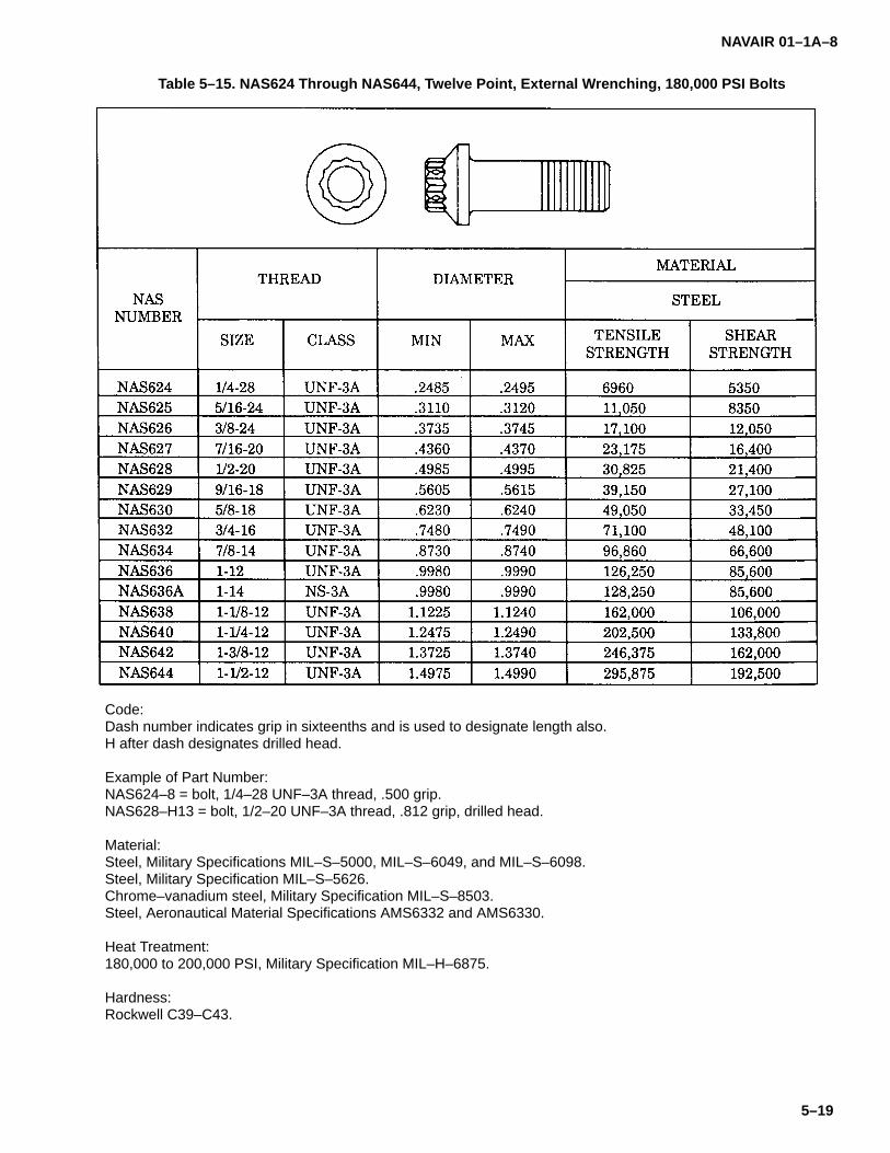
NAVAIR 01–1A–8
5–19
Table 5–15. NAS624 Through NAS644, Twelve Point, External Wrenching, 180,000 PSI Bolts
Code:Dash number indicates grip in sixteenths and is used to designate length also.H after dash designates drilled head.
Example of Part Number:NAS624–8 = bolt, 1/4–28 UNF–3A thread, .500 grip.NAS628–H13 = bolt, 1/2–20 UNF–3A thread, .812 grip, drilled head.
Material:Steel, Military Specifications MIL–S–5000, MIL–S–6049, and MIL–S–6098.Steel, Military Specification MIL–S–5626.Chrome–vanadium steel, Military Specification MIL–S–8503.Steel, Aeronautical Material Specifications AMS6332 and AMS6330.
Heat Treatment:180,000 to 200,000 PSI, Military Specification MIL–H–6875.
Hardness:Rockwell C39–C43.

NAVAIR 01–1A–8
5–20
Table 5–16. MS9033 Through MS9039, Twelve Point Head, Heat-Resistant Machine Bolts
Code:Dash number is used to designate grip and length.
Example of Part Number:MS9033–18 = bolt, 10–32 NS, length 1.250, grip .625.MS9039–14 = bolt, 9/16–18 NS, length 1.500, grip .125.
Material:Corrosion– and heat–resistant steel, Aeronautical Material Specification AMS5735.
Table 5–17. MS9088 Through MS9094, Drilled Twelve Point Head, Cadmium-plated Steel,Machine Bolts
Code:Dash number is used to designate grip and length.
Example of Part Number:MS9091–17 = bolt, 3/8–24 UNF–3A, length 1.438, grip .438.MF9093–26 = bolt, 1/2–20 UNF–3A, length 2.625, grip 1.375.
Material:Steel, Aeronautical Material Specification AMS6322.
Hardness:Rockwell C26–C32.

NAVAIR 01–1A–8
5–21
Table 5–18. NAS464 Close-tolerance Shear Bolt
Code:A after first dash number designates bolt without cotter pin hole.First dash number designates nominal diameter in sixteenths.Second dash number designates grip in sixteenths and is used to designate length.Example of Part Number:NAS464–3–12 = bolt, 3/4 grip, with cotter pin hole.NAS464–4A–16 = bolt, 1 grip, without cotter pin hole.
Material:Steel, Military Specifications MIL–S–5000, MIL–S–6049, and MIL–S–6098.Steel, Military Specification MIL–S–5626.Chrome–vanadium steel, Military Specification MIL–S–8503.Steel, Military Specification MIL–S–8695.
Heat Treatment:160,000 to 180,000 PSI, Military Specification MIL–H–6875.

NAVAIR 01–1A–8
5–22
Table 5–19. NAS563 Through NAS572, Full Threaded, Fully ldentified, Drilled Head Bolts
Code:Last digit of basic number indicates nominal diameter in sixteenths (NAS563 through NAS570 only).Dash number indicates length in thirty–seconds (NAS563 through NAS572 bolts are available in sixteenth incre-ments only).
Example of Part Number:NAS564–15 = bolt, full threaded, 1/4–28, length 15/32.NAS570–49 = bolt, full threaded, 5/8–18, length 1–17/32.
Material:Steel, Military Specifications MIL–S–6049, MIL–S–6050, MIL–S–6098, and MIL–S–18732.Steel, Military Specifications MIL–S–5626 and MIL–S–6758.Steel, Military Specification MIL–S–8695.Aluminum alloy, Federal Specifications QQ–A–267 and QQ–A–268.
Heat Treatment:160,000 to 180,000 PSI, Military Specification MIL–H–6875.
Hardness:Rockwell C36–C40.
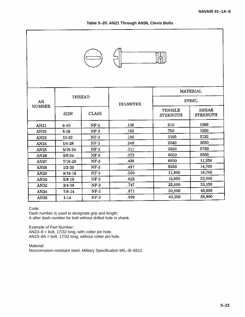
NAVAIR 01–1A–8
5–23
Table 5–20. AN21 Through AN36, Clevis Bolts
Code:Dash number is used to designate grip and length.A after dash number for bolt without drilled hole in shank.
Example of Part Number:AN23–8 = bolt, 17/32 long, with cotter pin hole.AN23–8A = bolt, 17/32 long, without cotter pin hole.
Material:Noncorrosion–resistant steel, Military Specification MIL–B–6812.
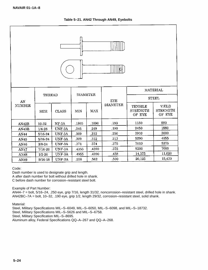
NAVAIR 01–1A–8
5–24
Table 5–21. AN42 Through AN49, Eyebolts
Code:Dash number is used to designate grip and length.A after dash number for bolt without drilled hole in shank.C before dash number for corrosion–resistant steel bolt.
Example of Part Number:AN44–7 = bolt, 5/16–24, .250 eye, grip 7/16, length 31/32, noncorrosion–resistant steel, drilled hole in shank.AN42BC–7A = bolt, 10–32, .190 eye, grip 1/2, length 29/32, corrosion–resistant steel, solid shank.
Material:Steel, Military Specifications MIL–S–6049, MIL–S–6050, MIL–S–6098, and MIL–S–18732.Steel, Military Specifications MIL–S–5626 and MIL–S–6758.Steel, Military Specification MIL–S–8695.Aluminum alloy, Federal Specifications QQ–A–267 and QQ–A–268.

NAVAIR 01–1A–8
5–25
Table 5–22. Interchangeability and Substitution of Protruding Head Bolts and Screws
Table 5–23. Interchangeability and Substitution of Flush Head Bolts and Screws
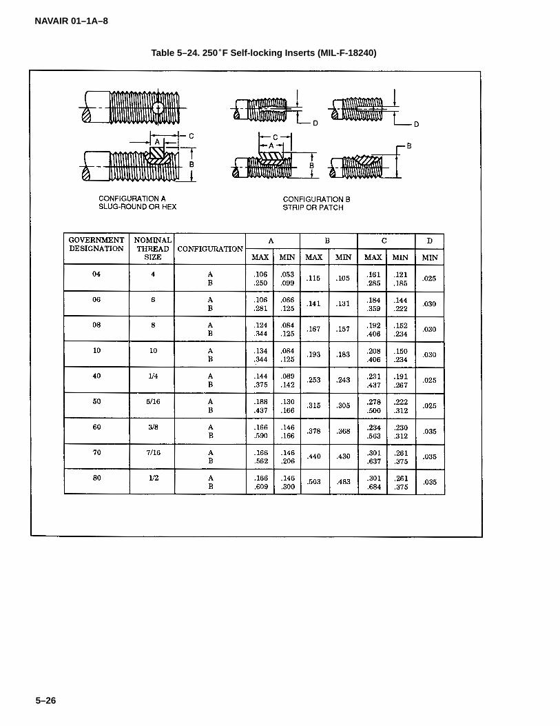
NAVAIR 01–1A–8
5–26
Table 5–24. 250�F Self-locking Inserts (MIL-F-18240)

NAVAIR 01–1A–8
5–27
Figure 5–3. Wrenching Recesses Figure 5–4. Damaged Recesses

NAVAIR 01–1A–8
5–28
e. Slotted. The slotted recess is a single, flat-bot-tomed slot. It is the most universally used recess.
f. Socket. The socket recess (NAS333) is an in-ternal, six-sided hexagon.
g. Torx. The Torx recess (NAS1800) has six shortdriving wings with rounded corners.
h. Tri-Wing. The Tri-Wing recess (NAS4000) hasthree drive wings.
5–24. INSTALLATION OF INTERNAL WRENCHINGFASTENERS. Use the following instructions for instal-ling internal wrenching fasteners:
a. Use only the driver bit which is designed for therecess being installed. Driver bits are not interchange-able. Do not overtorque internal wrenching fasteners.
b. Table 5-25 lists recommended torque values for160 KSI tensile strength fasteners. Overtorquing mayresult in cam-out.
c. Installation tools include screwdrivers, ratchets,and speed wrenches. Keep the driver in-line with thefastener axis to prevent cam-out of the fastener recessor damage to the driver. Apply sufficient force when us-ing speed wrenches to prevent the bit from disengagingthe recess, thereby damaging the fastener and scratch-ing or marring the structure.
5–25. REMOVAL OF INTERNAL WRENCHING FAS-TENERS. Screwdrivers, ratchets, and speed wrenchesmay be used for fastener removal. However, use careto prevent tool “wobble” which may result in bit cam-out.Clear away foreign material and paint from the recesswith a scribe or awl, using care not to damage the recessor adjacent structure. Remove the fastener by applyingtorque in a smooth, uniform motion. Ensure end load isgreat enough to prevent cam-out.
5–26. TOOLING FOR INTERNAL WRENCHING FAS-TENERS. Refer to Tables 5-26 through 5-31 for driverselection. Use only drivers conforming to the proper di-mensions for installation and removal. The drivernumber identifies the proper driver size for standard pro-truding head and 100� flush head fasteners. However,reduce 100� flush head fasteners have a recess one
size smaller then the standard head and requires thenext size smaller driver (see Figure 5-5).
5–27. TAPERED-SHANK FASTENERS.
5–28. Tapered-shank fasteners consist of a taperedshank bolt and a self-locking nut with captive washer.The bolt shank is tapered 1/4-inch per foot and finishedto close tolerance to provide a controlled interference fit.The tapered-shank induces the material in the joint tocompress elastically producing an excellent preloadcondition.
5–29. TOOLING FOR TAPERED-SHANK FASTEN-ERS. Prepare tapered holes using Taper-Lok TLDseries combination drill, drill-reamer and/or radius tools(refer to Tables 5-32 through 5-34). An example of thetool code is TLD2040 A-1-4: TLD2040 is the basic seriestool number. A designates tool type (drill radius-coun-tersink combination for 100� flush head fasteners), 1 isthe group number, and 4 indicates 1/4-inch nominal di-ameter. Other tool type designations are B (drill radiuscombination for protruding head fasteners), AR (reamerradius countersink combination for 100� flush head fas-teners), or BR (reamer radius combination forprotruding head fasteners). When hand drilling, use along travel microstop countersink cage (TLA4900).Check hole dimensions with hole gage assemblyTLG5100.
5–30. HOLE PREPARATION FOR TAPERED-SHANK FASTENERS. Drill a 1/64-inch undersize pilothole and ream to size with the appropriate drill-reamer(refer to Tables 5-32 through 5-34). Place the base ofthe countersink cage flat against the surface when dril-ling. Hole dimensions shall be within the limits of Tables5-35 and 5-36.
5–31. INSTALLATION OF TAPERED-SHANK FAS-TENERS. Use the following procedure for installingtapered-shank fasteners:
a. Insert bolt into hole.
b. Thread nut onto the bolt up to the locking ele-ment.
c. Torque the fastener by conventional wrenchingmethods in accordance with the values of Table 5-37.
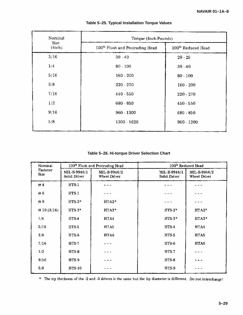
NAVAIR 01–1A–8
5–29
Table 5–25. Typical Installation Torque Values
Table 5–26. Hi-torque Driver Selection Chart

NAVAIR 01–1A–8
5–30
Table 5–27. Torq-set Driver Selection Chart
Table 5–28. Phillips Driver Selection Chart
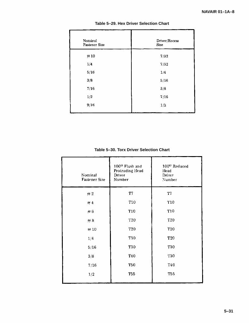
NAVAIR 01–1A–8
5–31
Table 5–29. Hex Driver Selection Chart
Table 5–30. Torx Driver Selection Chart

NAVAIR 01–1A–8
5–32
Table 5–31. Tri-wing Driver Selection Chart
Figure 5–5. Standard Head vs. Reduced Head
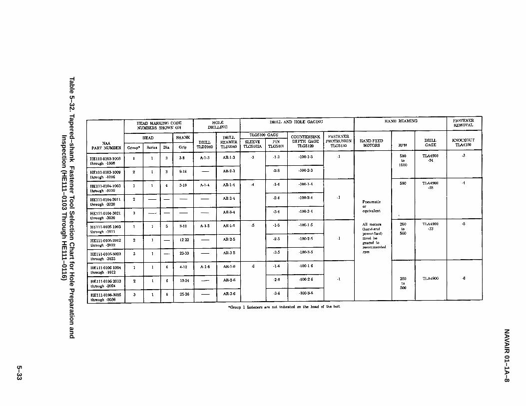
NA
VAIR
01–1A–8
5–33
Table 5–32. Tap
ered–sh
ank F
astener To
ol S
election
Ch
art for H
ole P
reparatio
n an
dIn
spectio
n (H
E111–0103 T
hro
ug
h H
E111–0116)
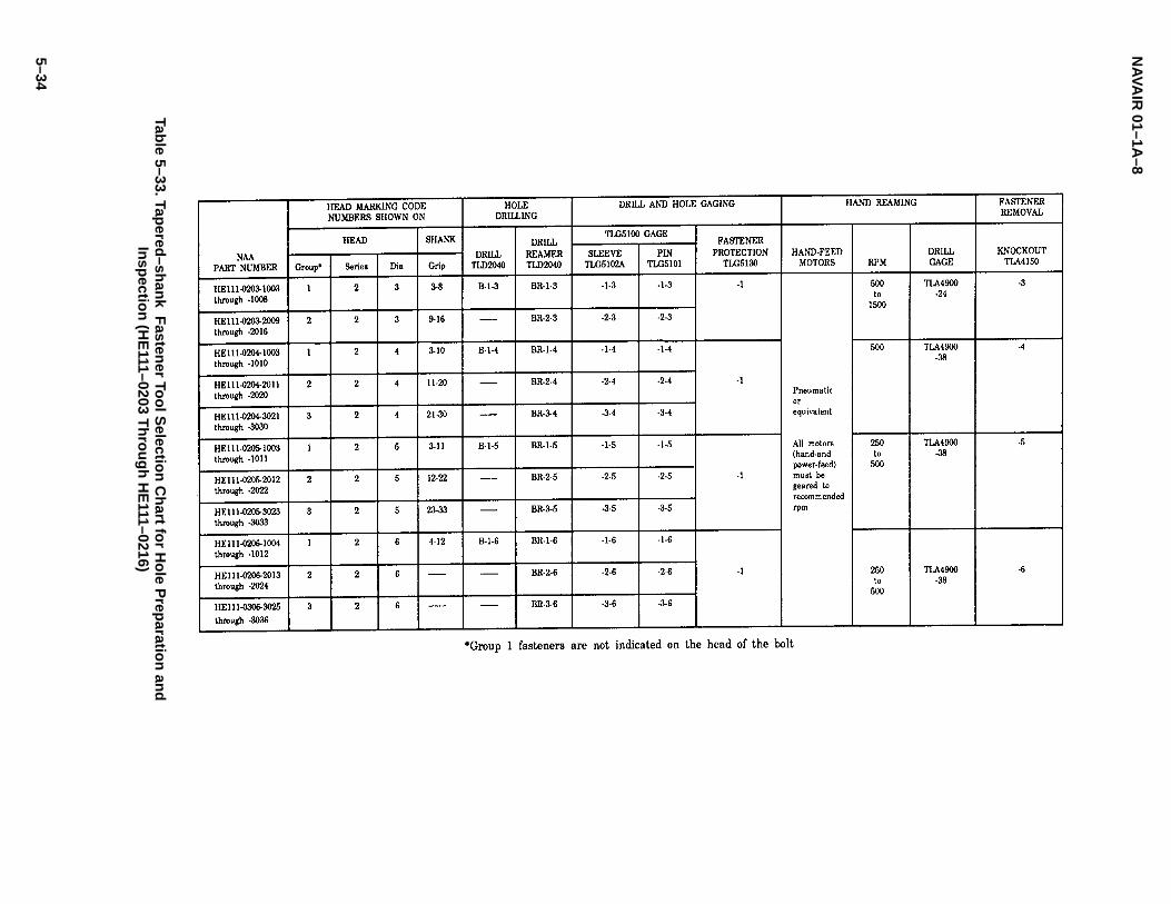
NA
VAIR
01–1A–8
5–34
Table 5–33. Tap
ered–sh
ank F
astener To
ol S
election
Ch
art for H
ole P
reparatio
n an
dIn
spectio
n (H
E111–0203 T
hro
ug
h H
E111–0216)

NA
VAIR
01–1A–8
5–35
Table 5–34. Tap
ered–sh
ank F
astener To
ol S
election
Ch
art for H
ole P
reparatio
n an
dIn
spectio
n (H
E111–0403 T
hro
ug
h H
E111–0416)

NAVAIR 01–1A–8
5–36
Table 5–35. Hole Dimensions for Flush Head Tapered-shank Fasteners
Table 5–36. Hole Dimensions for Protruding Head Tapered-shank Fasteners
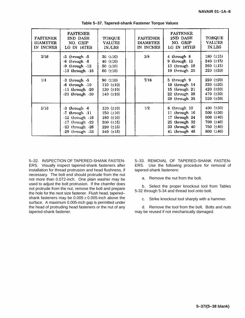
NAVAIR 01–1A–8
5–37/(5–38 blank)
Table 5–37. Tapered-shank Fastener Torque Values
5–32. INSPECTION OF TAPERED-SHANK FASTEN-ERS. Visually inspect tapered-shank fasteners afterinstallation for thread protrusion and head flushness, ifnecessary. The bolt end should protrude from the nutnot more than 0.072-inch. One plain washer may beused to adjust the bolt protrusion. If the chamfer doesnot protrude from the nut, remove the bolt and preparethe hole for the next size fastener. Flush head, tapered–shank fasteners may be 0.005�0.005-inch above thesurface. A maximum 0.005-inch gap is permitted underthe head of protruding head fasteners or the nut of anytapered-shank fastener.
5–33. REMOVAL OF TAPERED-SHANK FASTEN-ERS. Use the following procedure for removal oftapered-shank fasteners:
a. Remove the nut from the bolt.
b. Select the proper knockout tool from Tables5-32 through 5-34 and thread tool onto bolt.
c. Strike knockout tool sharply with a hammer.
d. Remove the tool from the bolt. Bolts and nutsmay be reused if not mechanically damaged.


NAVAIR 01–1A–8
6–1
SECTION VI
STUDS
6–1. STUDS.
6–2. Coarse thread, fine thread, stepped, and lock-ring studs are used in aircraft structural applications.Studs may be drilled or undrilled on the nut end.
6–3. IDENTIFICATION OF STUDS. Refer to Table6-1 for identification markings.
6–4. COARSE AND FINE THREAD STUDS. Coarse(NAS183) and fine (NAS184) thread studs are manufac-tured from alloy steel and heat-treated to 125 to 145 KSItensile strength (refer to Table 6-2). They have identicalthreads on both ends.
6–5. STEPPED STUDS. MS stepped studs have adifferent thread on each end of the stud (refer to Tables6-3 through 6-6).
6–6. STUD INSTALLATION. Use the following proce-dure for installation of studs:
a. Prepare holes for stud installation in accor-dance with the procedures provided in Section II.
b. Select the proper size stud. Stud installationtools are listed in Table 6-7. Install using driver/removerand collet and pin (see Figure 6-1).
c. Torque stud to value specified in Table 6-8. Ifproper torque is not observed at required stud height, re-move and install proper size stud.
CAUTION
Graphite-containing antiseize compoundsshall not be applied to tapped holes of alumi-num structures. Graphite is highly corrosiveto aluminum. Avoid using excessive lubri-cant.
6–7. STUD REMOVAL. Use the following procedurefor removal of studs (see Figure 6-2):
a. Insert adapter in stud remover (refer to Table6-7). Drive adapter down over threads.
b. Remove stud by turning stud remover withwrench.
c. If stud is not easily removed in this manner, cutstud off at the structure and drill a pilot hole in stud. Drill1/8-inch hole in 3/8-inch and smaller diameter studs.Drill 1/4-inch hole in 7/16-inch and larger diameterstuds.
d. Remove stud using removal tool (see figure6-3).
6–8. LOCKRING STUDS.
6–9. Lockring studs may be substituted for undersizeand oversize studs. The lockring prevents studs frombacking out due to vibration, stress, and/or temperaturevariations (see Figure 6-4). The outer serrations broachinto the substructure without distortion or concentratedstress. Lockring studs require a class 3 tapped hole forinstallation. Specially designed threads provide aninterference fit. Install and remove lockring studs as fol-lows:
a. Drill, counterbore, and tap a class 3 hole.
b. Install stud using stud wrench. Press in lockringmaking sure inner serrations of lockring align with serra-tions of stud (see Figure 6-5).
c. Remove lockring studs by milling out innerserrations of lockring and stud, and unthread stud. Iflockring fails to come out, collapse remaining portion ofring with punch (see Figure 6-6).
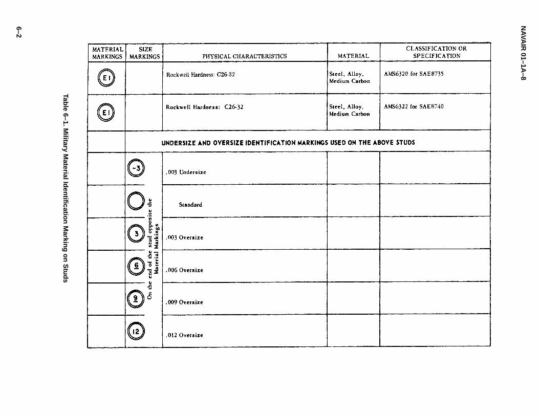
NA
VAIR
01–1A–8
6–2
Table 6–1. M
ilitary Material Id
entificatio
n M
arking
on
Stu
ds

NAVAIR 01–1A–8
6–3
Table 6–2. NAS183 and NAS184 Coarse and Fine Thread Studs
Code:First dash number indicates diameter in 1/16–inch increments.Second dash number indicates length in 1/8–inch increments.A after dash number indicates undrilled stud.
Examples of part numbers:NAS183–5–23 = coarse thread stud, 5/16–inch diameter, 2–7/8–inch long, drilled hole in stud.NAS184–5–23A = fine thread stud, 5/16–inch diameter, 2–7/8–inch long, undrilled.
Finish:Cadmium–plating per QQ–P–416.
Heat Treatment:125,000 to 145,000 psi per MIL–H–6875.
Material:Steel, MIL–S–6812.
Table 6–3. Stepped Studs, 1.5 Diameter Engagement
Material: Steel per AMS6322.Hardness: Rockwell C26–32.Finish: Cadmium–plate per AMS2400.
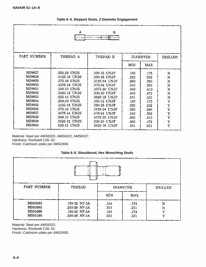
NAVAIR 01–1A–8
6–4
Table 6–4. Stepped Studs, 2 Diameter Engagement
Material: Steel per AMS6320, AMS6322, AMS6327.Hardness: Rockwell C26–32.Finish: Cadmium–plate per AMS2400.
Table 6–5. Shouldered, Hex Wrenching Studs
Material: Steel per AMS6322.Hardness: Rockwell C26–32.Finish: Cadmium–plate per AMS2400.
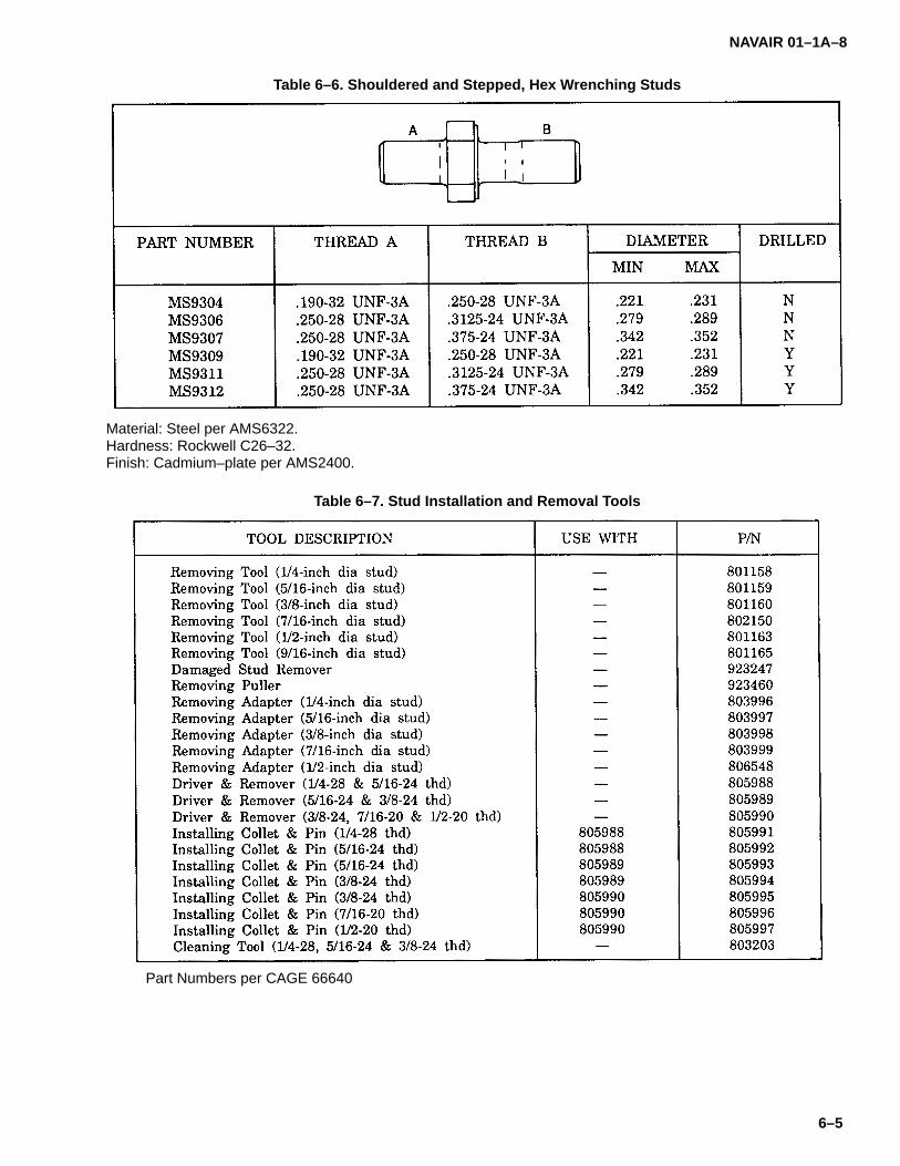
NAVAIR 01–1A–8
6–5
Table 6–6. Shouldered and Stepped, Hex Wrenching Studs
Material: Steel per AMS6322.Hardness: Rockwell C26–32.Finish: Cadmium–plate per AMS2400.
Table 6–7. Stud Installation and Removal Tools
Part Numbers per CAGE 66640
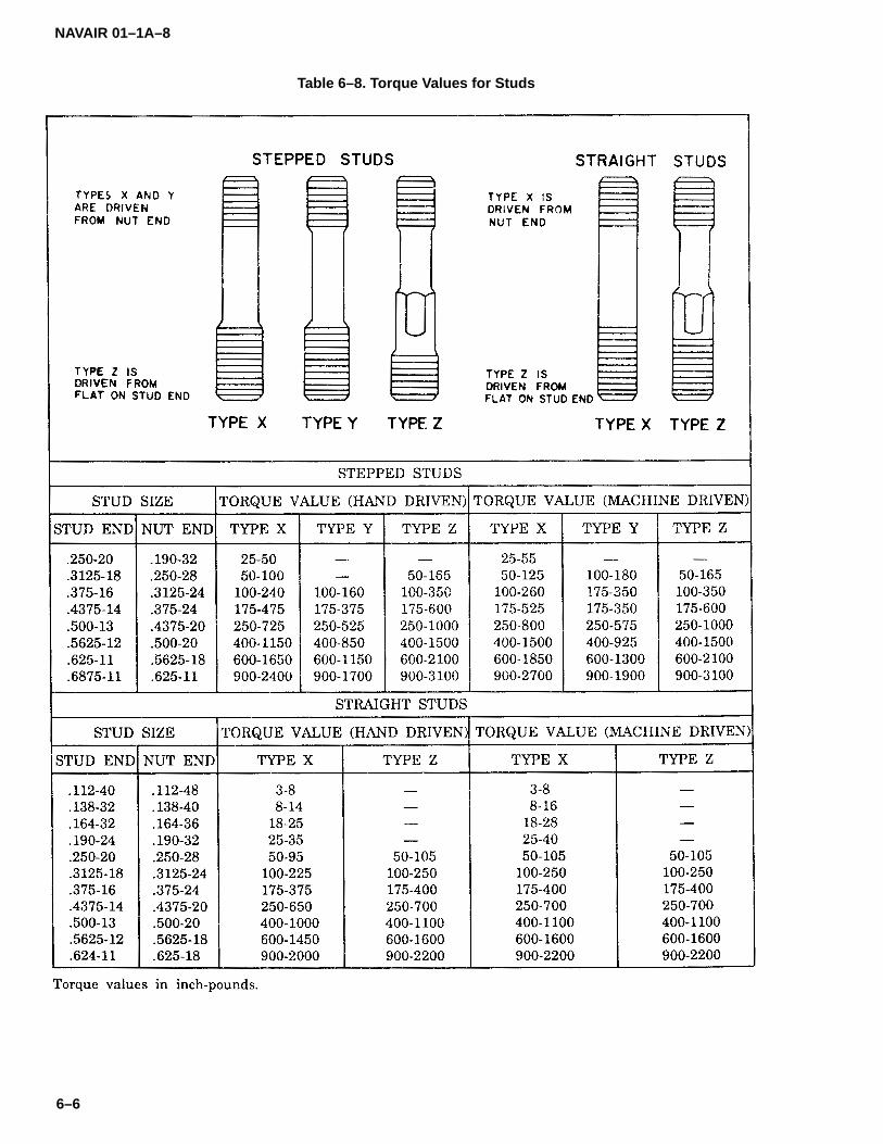
NAVAIR 01–1A–8
6–6
Table 6–8. Torque Values for Studs
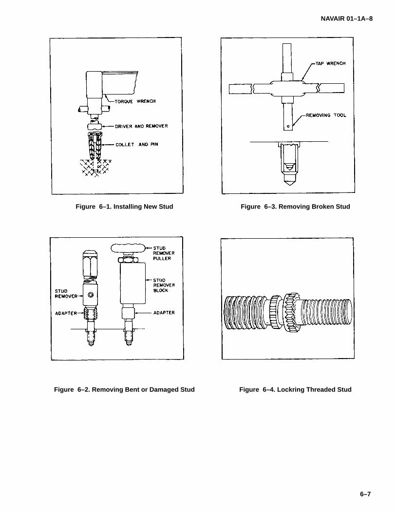
NAVAIR 01–1A–8
6–7
Figure 6–1. Installing New Stud
Figure 6–2. Removing Bent or Damaged Stud
Figure 6–3. Removing Broken Stud
Figure 6–4. Lockring Threaded Stud

NAVAIR 01–1A–8
6–8
Figure 6–5. Installation of Lockring Stud
Figure 6–6. Removal of Lockring Stud

NAVAIR 01–1A–8
7–1
SECTION VII
NUTS
7–1. NUTS.
7–2. Plain, castle, plate, gang channel, wing,12-point/spline, and clinch nuts are used in aircraftstructural applications. Most are available in self-lock-ing styles. The purpose of a nut is to provide a meansof loading a bolted assembly to a desired level. Sinceit is not economically feasible to manufacture nutthreads identical to those of the bolt, the nut must beplastic enough to allow the threads to deform upon tight-ening for an even load distribution. A nut should be noharder than that required to fully load the fastener as-sembly. Hardened nuts may actually damage boltthreads resulting in low tension and loss of preload.
7–3. IDENTIFICATION OF NUTS. Military andASTM (American Society for Testing and Materials)identification markings indicate material and physicalproperties, such as hardness and temperature limita-tions (refer to Table 7-1). The following are generalguidelines for temperature limitations of nuts:
a. 250�F Nuts. Non-metallic insert nuts shall notbe used in applications subject to temperatures exceed-ing 250�F.
b. 450�F Nuts. Cadmium-plated nuts shall not beused in applications subject to temperatures exceeding450�F.
c. 800�F Nuts. 800�F CRES nuts shall not beused in applications subject to temperatures exceeding800�F. These may be silver-plated.
d. 1200�F Nuts. 1200�F nuts shall be silver-plated and identified as follows:
1. Configuration. 1200�F nuts are designatedby the MS20500 series.
2. Plating. 1200�F nut threads shall be silver-plated per MIL-N-7873 (the entire nut may besilver-plated). Silver plating provides lubrication andprevents seizing. Note that silver plating alone is not anindication the nut is 1200�F rated (800�F nuts are alsosilver-plated). Non-silver-plated nuts shall not be usedin applications subject to temperatures exceeding800�F.
3. Markings. MS20500 series high tempera-ture nuts may be stamped with a 12. Commercial serieshigh temperature nuts may be stamped H4, H4-R, orH19.
7–4. SELF-LOCKING NUT FINISHES. Self-lockingnuts are manufactured with several types of finishes,depending upon environmental and temperature re-quirements:
a. Cadmium Plating. Cadmium is electrolyticallydeposited and provides protection in corrosive environ-ments. Cadmium-plated nuts shall not be used inapplications subject to temperatures in excess of 450�F.Cadmium will diffuse into the base material when sub-jected to high temperatures resulting in brittleness andpossible failure.
b. Silver Plating. Silver plating is applied to hightemperature nuts. Advantages include heat resistanceup to 1400�F and excellent lubrication characteristics.Silver provides high load carrying capability and resistsgalling and seizing of mating parts when subjected toheat or pressure extremes.
c. Aluminum Anodizing. An oxide coating isformed on the surface by connecting the metals asanodes in an electrolyte. The coating offers excellentcorrosion resistance and may be dyed in several colors.
d. Solid Film Lubricant. Molybdenum disulfidemay be applied to nuts for lubrication purposes. It pro-vides a clean, dry, permanently bonded coating whichprevents seizing and galling of threads. Molybdenumdisulfide may be applied to cadmium and silver platednuts.
7–5. TORQUING BOLTED ASSEMBLIES. Table 7-2provides recommended torque values for fine andcoarse thread series nuts. Apply sufficient preload tobolted assemblies to prevent fatigue failure, creeping orshifting, or back-off of the nut. Ideally, a fastener assem-bly should be torqued just below the yield strength toprovide a cushion for working load variations and to pre-vent loosening. Table 7-3 lists minimum prevailingtorque values for standard torque wrenches on usedself-locking nuts. Free-spinning nuts are not subject tothe torque values of Table 7-3 (refer to paragraph 7-11).Refer to Section II for further information on torque.

NAVAIR 01–1A–8
7–2
Table 7–1. Identification Markings on Nuts

NAVAIR 01–1A–8
7–3
Table 7–2. Recommended Torque Values (Inch-Pounds)

NAVAIR 01--1A--8
7--4 Change 1
Table 7--3. Minimum Prevailing Torque Values for Reused Self-Locking Nuts
COARSE THREAD SERIES
NOTE
The minimum prevailing torque is estab-lished when the fastener fully engages thelocking insert of the nut.
7--6. FATIGUE FAILURE. Fatigue failures, account-ing for most fastener failures, are caused by insufficienttorquing and lack of pre-load which results in shifting ofthe fastened assembly and cyclic stressing of the fas-tener. Eventually, a crack will form at the high stresspoint and grow as the joint is further stressed. The fas-tener becomes too weak to support the load, ultimatelyresulting in separation of the fastener shank.
7--7. THREAD PROTRUSION. A minimum of twothread pitches, including the chamfered end, shall pro-trude through the nut. The chamfered bolt end provideseasy mating of the nut and bolt, but results in undersizelead threads. The significance of the lead threads de-pends upon nut size and thread pitch variations. Forexample, a 1-inch, UNF thread, regular height nut has10.5 threads; the two lead threads make up 19% of thetotal thread length. A 1/4-inch, UNC thread, regularheight nut has 4.4 threads; the two lead threads makeup 45% of the total thread length. The number of pro-truding threads should be kept at a minimum as excessbolt length adds weight and cost to the aircraft. If a boltis too long, the nut may bottom out against the griplength (unthreaded portion) of the bolt before reachingits proper load.
CAUTION
Do not replace regular nuts with light-weight nuts in critical engine applications.
7--8. LIGHTWEIGHT NUTS. Lightweight nut applica-tions use shorter studs or bolts than those required forregular nuts. Thus, regular nuts shall not be substitutedfor lightweight nuts when reduced-length studs areused. Lightweight nuts may be substituted for regularnuts, but regular nuts may not be universally substitutedfor lightweight nuts.
7--9. SELF-LOCKING NUTS.
CAUTION
Unless otherwise stated in the specificoverhaul manual, self--locking nuts shallnot be used in critical applications, suchas joints in control systems, or in areaswhere loss of the bolt would affect safetyof flight, and if used, they shall be usedonly in accordance with the limitations ofpara. 7--10. Examples of critical applica-tions include engines where a loosefastener may be drawn into the air intakeduct; on axes of rotation, such as pulleys,cranks, and linkages; or in the attachmentof access panels or doors. When self--locking nuts are installed in criticalapplications, a new self--locking nut shallbe used. Do not re--use self--locking nutsin critical applications.
NAVAIR 01–1A–8
7–5
7–10. Self-locking nuts meet critical specifications re-garding strength, corrosion resistance, and temperaturelimitations. They shall not be used at joints in controlsystems when movement of the joint may result in mo-tion of the nut relative to the surface against which it isbearing. They may be used with antifriction bearingsand control pulleys only if the inner race of the bearingis clamped to the supporting surfaces by the nut andbolt. The nuts attached to the structure shall be attachedin a positive manner to eliminate the possibility of rota-tion, and the manner of attachment shall permit removalof the nut without causing damage to the structure. Thefollowing are MS self-locking nuts:
a. MS21042 450�F, reduced height, reduced hex,self-locking nuts with a ring base (refer to Table 7-4).
b. MS21043 800�F, reduced height, reduced hex,self-locking nuts with a ring base manufactured from sil-ver-plated CRES (refer to Table 7-5).
c. MS21044 250�F, regular series, regular height,all metal or non-metallic insert self-locking nuts. Theyare made from carbon steel, aluminum alloy, or CRESwith strengths of 60 KSI or 125 KSI (refer to Table 7-6).
d. MS21045 450�F, regular height, regular series,125 KSI, self-locking hex nuts available in cadmium-plated steel or CRES (refer to Table 7-7).
e. MS21046 800�F, regular height, regular series,self-locking hex nuts available in silver-plated CRES(refer to Table 7-8).
NOTE
Tables 7-9 through 7-13 are cross-refer-ence charts for MS21042-MS21046self-locking nuts.
7–11. TYPES OF SELF-LOCKING NUTS. Prevailingtorque and free-spinning are two types of self-lockingnuts. Prevailing torque nuts require wrenching through-out the installation cycle after the bolt or screw hasengaged the frictional part of the nut. Free-spinningnuts turn freely until seated. Further tightening providesthe locking action.
a. Prevailing Torque Nuts. The following arestyles of prevailing torque self-locking nuts:
1. Non-Metallic Insert Nuts. A nylon insertwith a smaller inside diameter than the major bolt diame-ter exerts a compressive locking force against the bolt.Before reuse, ensure the insert has not lost its lockingfriction or become brittle. Non-metallic insert nuts shallnot be subjected to temperatures exceeding 250�F.
2. Slotted or Beam Nuts. These nuts have atapered, slotted top, which is depressed inward to forma functional locking element.
3. Deformed Thread Nuts. Locking is causedby friction when the bolt forces out-of-round threads intoa round shape.
4. Interrupted Thread Nuts. These nuts areessentially two nuts combined: the lower portion carriesthe load and the upper portion provides the locking ac-tion. The top threads offset axially downward. When abolt enters the upper portion, it springs these threads tolock the nut (see Figure 7-1).
b. Free-Spinning Nuts. The following are styles offree-spinning self-locking nuts:
CAUTION
Free-spinning nuts shall be used onlywhen specified in the applicable technicalmanual. These nuts are not suitable forgeneral aircraft use.
1. Free-Spinning On-Off Nuts. These nutsconsist of a split and tapered, threaded core keyed intoa metal shell. The small end of the taper is at the bottomof the nut. When the outer shell contacts the bearingsurface, torquing of the nut forces the core downward toproduce a locking action. These nuts are free-spinningon until contact is made with the bearing surface andfree-spinning off after being backed away from the bear-ing surface (see Figure 7-2).
2. Free-Spinning On-Residual Torque OffNuts. These nuts consist of a split core which floats in-side a metal shell. The shell dimple seats in the coregroove and the nut is free-spinning on until contact withthe bearing surface. Torquing compresses the core intothe locking position. The nut retains high prevailingtorque while being backed out until, after three turns, afirm blow will reseat the shell dimple into the coregroove, allowing free-spinning removal (see Figure7-3).
3. Stressed Nuts. These nuts are free-spin-ning on and off, but have a higher seating torque thanother free-spinning nuts. They have a ground washeraround the outside circumference of the lower portion ofthe nut. When torqued, the washer compresses produc-ing a locking force on the inner threaded section (seeFigure 7-4).
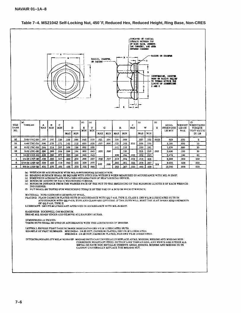
NAVAIR 01–1A–8
7–6
Table 7–4. MS21042 Self-Locking Nut, 450�F, Reduced Hex, Reduced Height, Ring Base, Non-CRES

NAVAIR 01–1A–8
7–7
Table 7–5. MS21043 Self-Locking Nut, 800�F, Reduced Hex, Reduced Height, Ring Base, CRES

NAVAIR 01–1A–8
7–8
Table 7–6. MS21044 Self-Locking Nut, 250�F, 125 KSI Ftu and 60 KSI Ftu
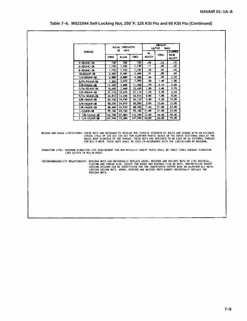
NAVAIR 01–1A–8
7–9
Table 7–6. MS21044 Self-Locking Nut, 250�F. 125 KSI Ftu and 60 KSI Ftu (Continued)
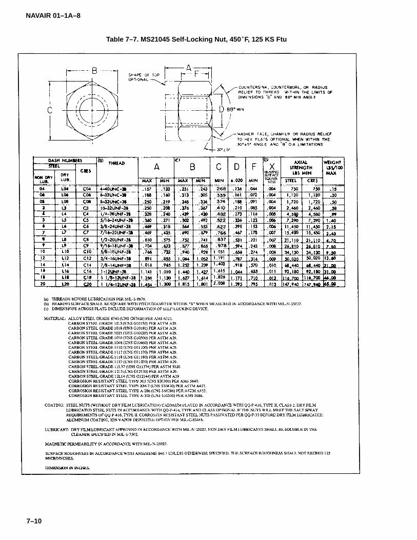
NAVAIR 01–1A–8
7–10
Table 7–7. MS21045 Self-Locking Nut, 450�F, 125 KS Ftu

NAVAIR 01–1A–8
7–11
Table 7-7. MS21045 Self-Locking Nut, 450�F, 125 KSI Ftu (Continued)
NOTE
Free-spinning nuts requiring less than 10inch-pounds of torque to break away shallnot be reused. Reused free-spinning nutsshall not be deformed or damaged.
7–12. TYPES OF NUTS.
7–13. The following types of nuts are available for usein aircraft applications:
NOTE
Due to the large number of MS nuts, it isnot practical to include all drawings in thisgeneral manual. Thus, one or two exam-ples of each type of nut is provided. Forfurther information refer to Military Speci-fications and Standards index.
a. Plain Nuts. Plain UNC-2B and UNF-2B nuts areused in general aircraft structural and nonstructural ap-plications and are available with a self-locking feature.Non-locking plain nuts shall be secured with a lock-washer or other locking device. Plain nuts are madefrom carbon steel, CRES, or brass (refer to Table 7-14).
b. Castle Nuts. MS17825 nuts are 250�F regularheight, self-locking castle nuts made from cadmium-plated alloy steel with non-metallic inserts (refer to Table7-15). MS17826 nuts are similar to MS17825 nuts, ex-cept they are lightweight, lower torque, reduced height
nuts (refer to Table 7-16). Castle nuts are used in criticalapplications, such as joints in aircraft control systemsand installation of pulleys, cranks, linkages, etc. Securecastle nuts with cotter pins or safety wire in accordancewith Section II.
c. Plate Nuts. Plate nuts are used in blind mount-ing applications. They are available in 2-lug, 1-lug, andcorner designs (refer Tables 7-17 through 7-22). Platenuts are available with several features including self-locking, low height, floating, high-temperature, andreduced rivet designs. They are also available in flushhead and protruding head designs. Floating plate nutsprovide a controlled amount of movement to compen-sate for assembly misalignment.
d. Gang Channels. Gang channels are used in ap-plications requiring anchored nuts equally spacedaround an inspection door, access door, etc. Nut ele-ments are made from carbon steel, alloy steel, or CRES.Channels are made from aluminum alloy or CRES.Gang channels offer a wide range of nut spacings andprovide a multiple nut unit that has the advantages offloating type nuts (refer to Table 7-23). Gang channelsare generally self-locking.
e. Wingnuts. MS35425 plain wingnuts areinstalled by hand and require no tooling for installationand removal. They are used in non-structural applica-tions and removal. They are used in non-structuralapplications requiring frequent assembly and disas-sembly. Wingnuts are manufactured from carbon steelor brass with UNC-2B threads (refer to Table 7-24).

NAVAIR 01–1A–8
7–12
Table 7–8. MS21046 Self-Locking Nut, Regular Height. 800�F, 125 KSI Ftu

NAVAIR 01–1A–8
7–13
Table 7–9. Cross Reference on Nuts Replaced by MS21042
Table 7–10. Cross Reference on Nuts Replaced by MS21043

NAVAIR 01–1A–8
7–14
Table 7–11. Cross Reference on Nuts Replaced by MS21044

NAVAIR 01–1A–8
7–15
Table 7-11. Cross Reference on Nuts Replaced by MS21044 (Continued)

NAVAIR 01–1A–8
7–16
Table 7–12. Cross Reference on Nuts Replaced by MS21045
Table 7–13. Cross Reference on Nuts Replaced by MS21046
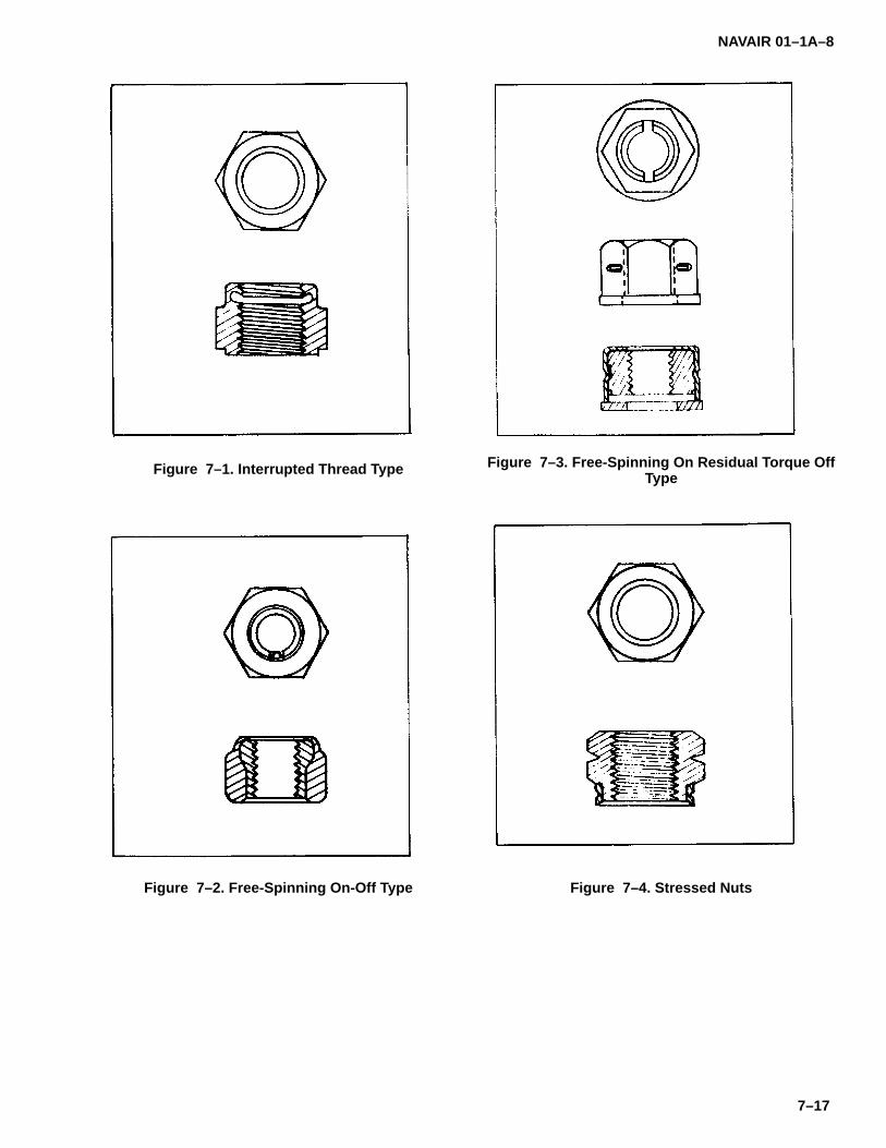
NAVAIR 01–1A–8
7–17
Figure 7–1. Interrupted Thread Type
Figure 7–2. Free-Spinning On-Off Type
Figure 7–3. Free-Spinning On Residual Torque OffType
Figure 7–4. Stressed Nuts

NAVAIR 01–1A–8
7–18
Table 7–14. MS35690 Plain Hex Nut, UNC-2B and UNF-2B

NAVAIR 01–1A–8
7–19
Table 7–15. MS17825 250�F Self-Locking Castle Nut, Non-Metallic Insert

NAVAIR 01–1A–8
7–20
Table 7–16. MS17826 250�F Self-Locking Castle Nut, Thin, Non-Metallic Insert
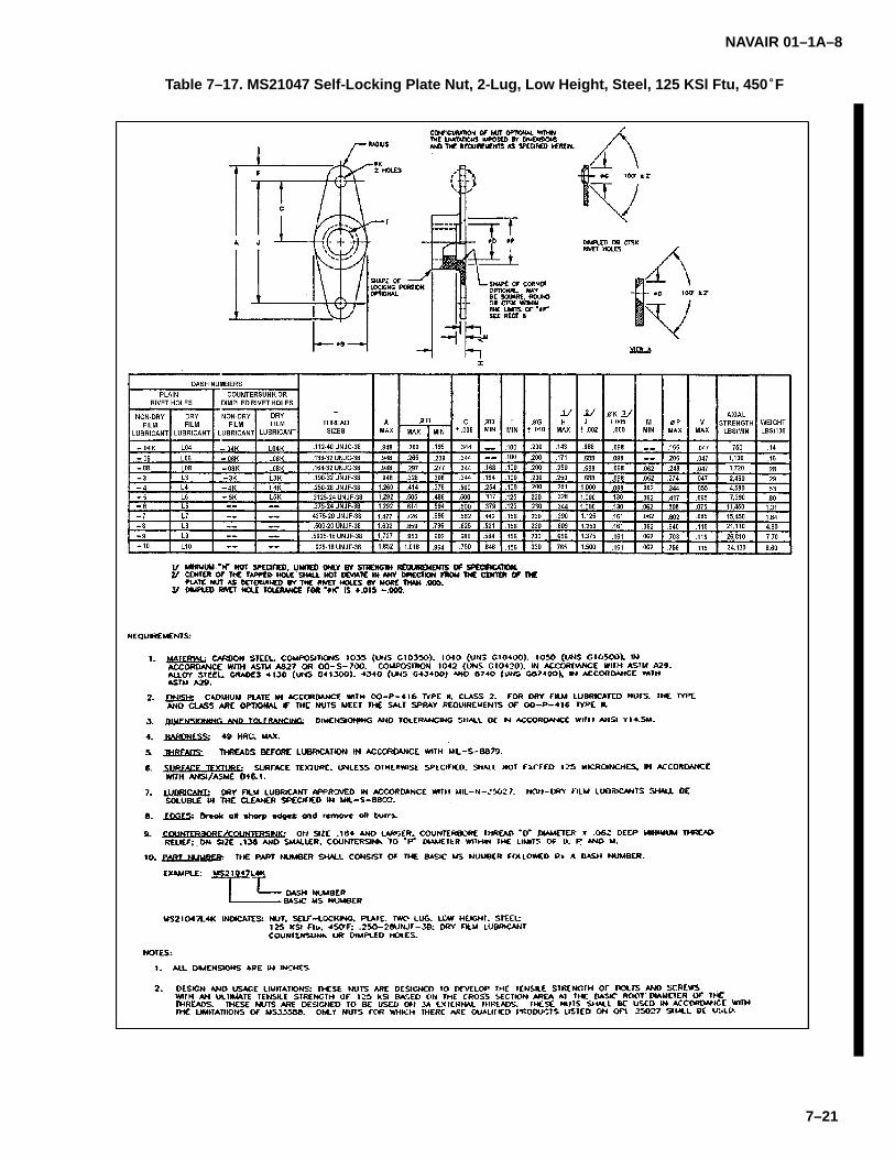
NAVAIR 01–1A–8
7–21
Table 7–17. MS21047 Self-Locking Plate Nut, 2-Lug, Low Height, Steel, 125 KSl Ftu, 450�F

NAVAIR 01–1A–8
7–22
Table 17. MS21047 Self-Locking Plate Nut, 2-Lug, Low Height, Steel, 125 KSl Ftu, 450�F (Continued)

NAVAIR 01–1A–8
7–23
Table 7–18. MS21048 Self-Locking Plate Nut, 2-Lug, Low Height, CRES, 125 KSl Ftu, 450�F & 800�F
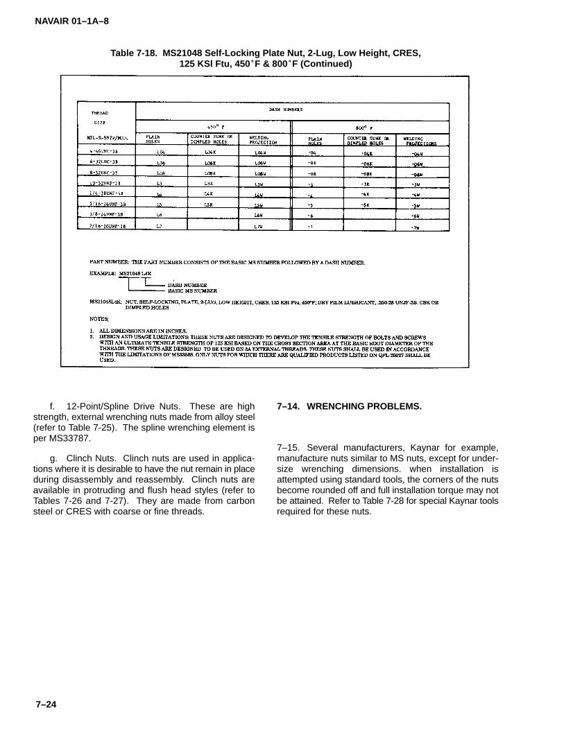
NAVAIR 01–1A–8
7–24
Table 7-18. MS21048 Self-Locking Plate Nut, 2-Lug, Low Height, CRES,125 KSl Ftu, 450�F & 800�F (Continued)
f. 12-Point/Spline Drive Nuts. These are highstrength, external wrenching nuts made from alloy steel(refer to Table 7-25). The spline wrenching element isper MS33787.
g. Clinch Nuts. Clinch nuts are used in applica-tions where it is desirable to have the nut remain in placeduring disassembly and reassembly. Clinch nuts areavailable in protruding and flush head styles (refer toTables 7-26 and 7-27). They are made from carbonsteel or CRES with coarse or fine threads.
7–14. WRENCHING PROBLEMS.
7–15. Several manufacturers, Kaynar for example,manufacture nuts similar to MS nuts, except for under-size wrenching dimensions. when installation isattempted using standard tools, the corners of the nutsbecome rounded off and full installation torque may notbe attained. Refer to Table 7-28 for special Kaynar toolsrequired for these nuts.
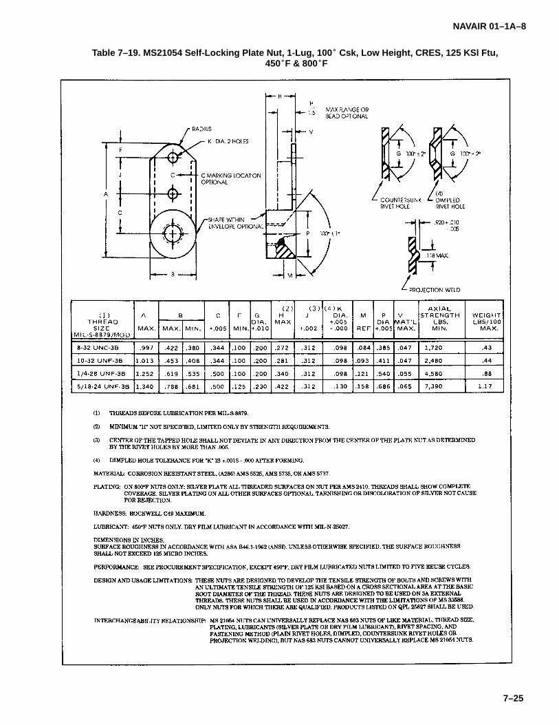
NAVAIR 01–1A–8
7–25
Table 7–19. MS21054 Self-Locking Plate Nut, 1-Lug, 100� Csk, Low Height, CRES, 125 KSl Ftu, 450�F & 800�F

NAVAIR 01–1A–8
7–26
Table 7-19. MS21054 Self-Locking Plate Nut, 1-Lug, 100� Csk, Low Height, CRES, 125 KSl Ftu,A50�F & 800�F (Continued)
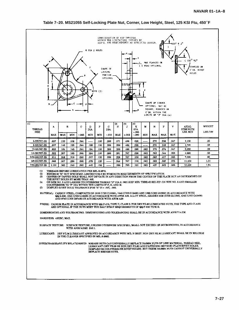
NAVAIR 01–1A–8
7–27
Table 7–20. MS21055 Self-Locking Plate Nut, Corner, Low Height, Steel, 125 KSI Ftu, 450�F
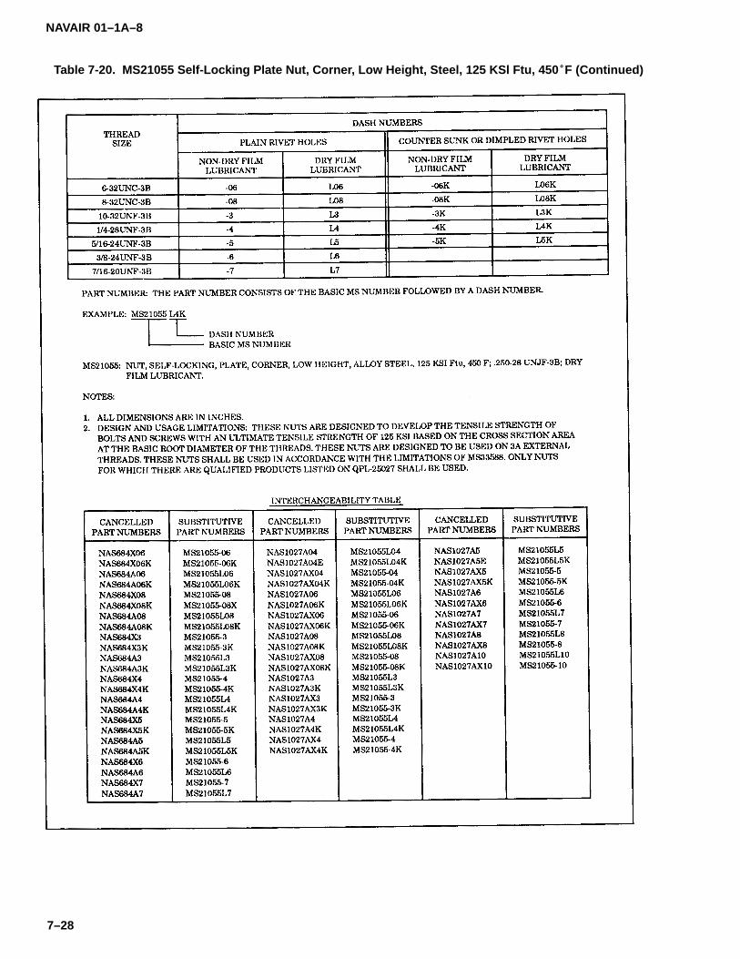
NAVAIR 01–1A–8
7–28
Table 7-20. MS21055 Self-Locking Plate Nut, Corner, Low Height, Steel, 125 KSl Ftu, 450�F (Continued)

NAVAIR 01–1A–8
7–29
Table 7–21. MS21059 2-Lug Floating Plate Nut
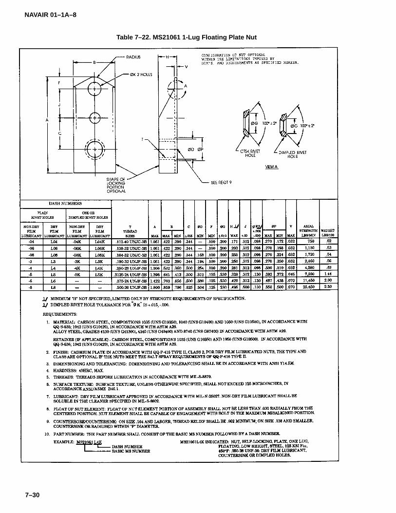
NAVAIR 01–1A–8
7–30
Table 7–22. MS21061 1-Lug Floating Plate Nut
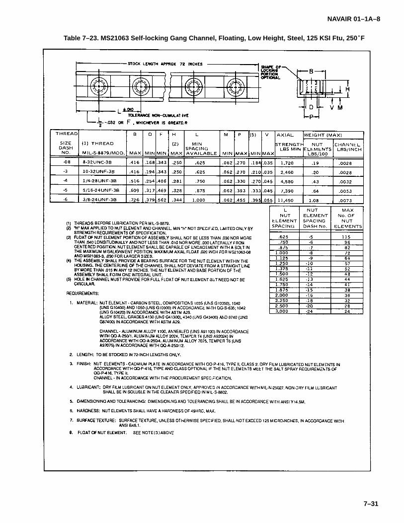
NAVAIR 01–1A–8
7–31
Table 7–23. MS21063 Self-locking Gang Channel, Floating, Low Height, Steel, 125 KSI Ftu, 250�F

NAVAIR 01–1A–8
7–32
Table 7-23. MS21063 Self-Locking Gang Channel, Floating, Low Height, Steel, 125 KSI Ftu, 250�F (Continued)
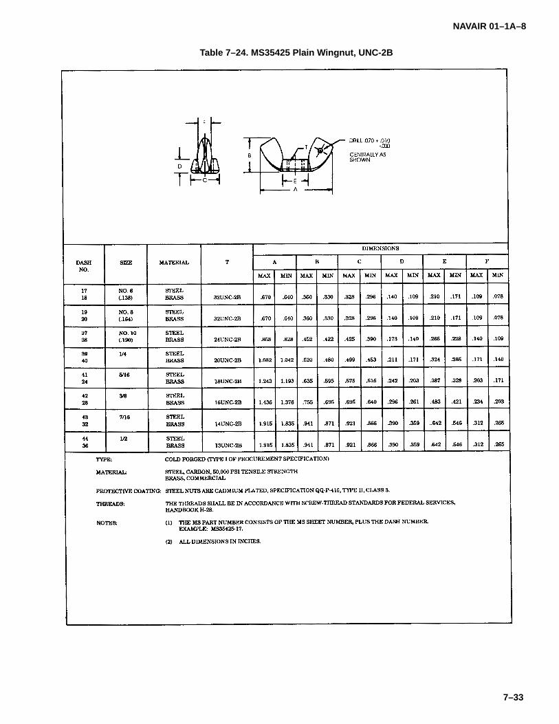
NAVAIR 01–1A–8
7–33
Table 7–24. MS35425 Plain Wingnut, UNC-2B

NAVAIR 01–1A–8
7–34
Table 7–25. MS21084 Self-Locking, 450�F, 12-Point Flanged Nut
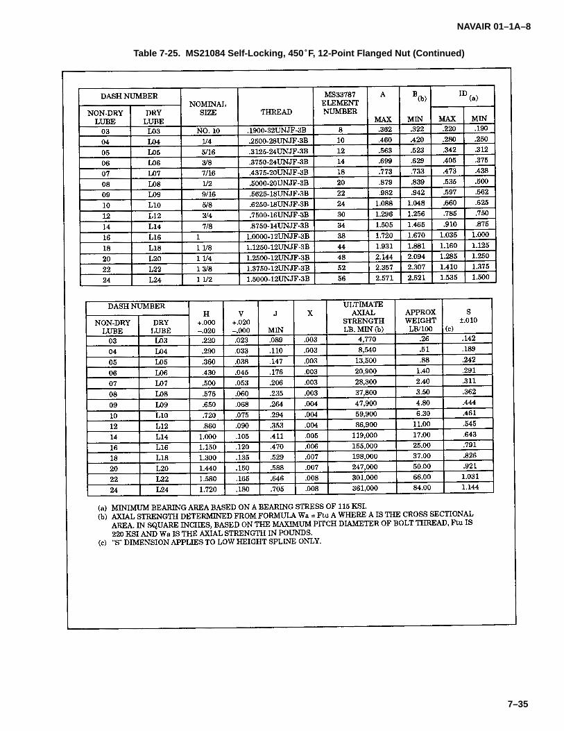
NAVAIR 01–1A–8
7–35
Table 7-25. MS21084 Self-Locking, 450�F, 12-Point Flanged Nut (Continued)

NAVAIR 01–1A–8
7–36
Table 7–26. Plain Clinch Nut

NAVAIR 01–1A–8
7–37
Table 7–27. Flush Clinch Nut

NAVAIR 01–1A–8
7–38
Table 7–28. Special Wrenches Required for Some Kaynar Locknuts

NAVAIR 01–1A–8
8–1
SECTION VIII
WASHERS
8–1. WASHERS.
8–2. Flat, flush locking, and key washers are used inaircraft applications. Minimum alloy washers shall beused in conjunction with aluminum or magnesium struc-tures where corrosion due to dissimilar metals is afactor. The resulting galvanic coupling will not involvethe surface material. However, where greater strengthis required, a cadmium-plated steel washer shall beused with the washer bearing directly against the struc-ture. Steel washers will resist the cutting action of thenut or bolt better than aluminum washers.
8–3. TYPES OF WASHERS.
8–4. The following types of washers are used in air-craft structural applications:
a. Flat Washers. Flat washers provide a smoothbearing surface and act as shims to provide the properthread protrusion. They may be used to adjust the posi-tion of castle nuts with respect to cotter pin holes andunder lockwashers to prevent damage to soft material(refer to Tables 8-1 through 8-5).
b. Flush Washers. Flush washers are used underthe head of flush head bolts and screws. They are avail-able in steel and brass and accept #10 to 1/2-inch boltsizes (refer to Tables 8-5 and 8-6).
�������
Lockwashers shall not be used on primaryor secondary structures, superstructures,or in applications where failure may resultin damage or danger to aircraft or person-nel.
CAUTION
Use a plain washer under a lockwasheron soft metals, such as aluminum or mag-nesium, to prevent damaging the surface.Lockwashers shall not be used where fail-ure may cause a leak, on surfacesexposed to airflow, in applications subjectto corrosive conditions, or where theymust be removed frequently.
c. Lockwashers. Lockwashers and tooth-lockwashers are used with plain nuts when self-locking orcastle nuts are not applicable. Tooth-lock washers areavailable with internal, external, or combination toothstyles (refer to Tables 8-7 through 8-12). The spring ac-tion of the washer prevents the nut from loosening.Lockwashers may be used in the following applications:
1. Locking of threaded fasteners which do nothave a self-locking feature.
2. Where use of a cotter pin or lockwire is notfeasible.
3. Fastening non-primary structures.
4. Where loose fasteners will not endangerthe safety of the aircraft or personnel.
d. Key Washers. Key washers are available inalloy steel and CRES in a variety of styles (refer toTables 8-13 and 8-14).
e. Rod End Washers. NAS513 washers are usedto lock rod ends when installed on control rods (refer toSection XIV). Refer to Table 8-15.
f. Countersunk Washers. Countersunk washers(refer to Table 8–5) are used under the heads of boltswith a radius between the head and shank. The counter-sink provides relief for bolt head to shank radius,allowing a smooth seating surface for the bolt. Thewasher is installed on the bolt with the countersunk sidetoward the bolt head (refer to Figure 8–1).
CAUTION
Improper countersunk washer installationcould result in bolt failure.

NAVAIR 01–1A–8
8–2
Table 8–1. AN960 Washer

NAVAIR 01–1A–8
8–3
Table 8-1. AN960 Washer (Continued)
Code:Material–designating letter or letters before dash number are as specified above wider dash numbers.Dash number from 3 to 10 is bolt size.Dash number from 416 to 4016 indicates bolt diameter in 1/16 inch.
Example of part number:AN960–716 = washer, cadmium–plated carbon steel, for 7/16–inch diameter bolt.AN960PD10L = washer, light series, treated surface clad aluminum alloy, for number 10 bolt.
Material:Carbon steel, Military Specification MIL–S–7952.Corrosion–resistant steel, AMS 5510 or AMS 5512.Aluminum alloy alclad 2024, condition T3 or T4, Federal Specification QQ–A–250/5.Copper, ASTM B152.Brass, ASTM B36 or ASTM B121.
Finish:Anodize, Military Specification MIL–A–8625 or chemical treatment, Military Specification MIL–C–5541, Class 3 (For clad aluminum alloy and aluminum washers where specified).Cadmium plating, Federal Specification QQ–P–416, Type II, Class 2 (For carbon steel washers only).
*Unless otherwise specified, tolerances are as follows: Decimals + .010, on thickness for aluminum or aluminumalloy washers; .016 � .003; .032 � .004; .064 � .006; .090 � .007.
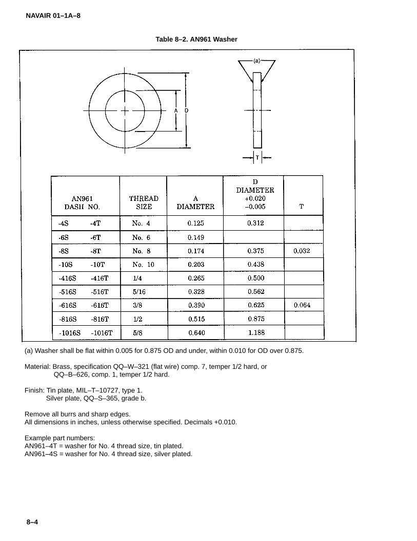
NAVAIR 01–1A–8
8–4
Table 8–2. AN961 Washer
(a) Washer shall be flat within 0.005 for 0.875 OD and under, within 0.010 for OD over 0.875.
Material: Brass, specification QQ–W–321 (flat wire) comp. 7, temper 1/2 hard, or QQ–B–626, comp. 1, temper 1/2 hard.
Finish: Tin plate, MIL–T–10727, type 1.Silver plate, QQ–S–365, grade b.
Remove all burrs and sharp edges.All dimensions in inches, unless otherwise specified. Decimals +0.010.
Example part numbers:AN961–4T = washer for No. 4 thread size, tin plated.AN961–4S = washer for No. 4 thread size, silver plated.

NAVAIR 01–1A–8
8–5
Table 8–3. AN970 Washer
Code:Dash number indicates bolt diameter in 1/16 inch.Example of part number:AN970–4 = washer for 1/4–inch diameter bolt.
Material:Steel.
Finish:Cadmium plating, Federal Specification QQ–P–416.The AN970 washer is used in wooden structures under both bolt head and nut to prevent crushing of the surface.
Figure 8–1. Proper Countersunk Washer Installation

NAVAIR 01–1A–8
8–6
Table 8–4. NAS620 Washer
Code:A before dash number indicates aluminum alloy washer.B before dash number indicates brass washer.Dash number from 0 to 10 is bolt size. Dash number 416 indicates bolt diameter in 1/16 inch.
Example of part number:NAS620–10 = washer, cadmium–plated low carbon steel, for number 10 bolt.NAS620A10L = washer, light series, 52S aluminum alloy, for number 10 bolt.NAS620B10 = washer, cadmium–plated brass, for number 10 bolt.
Material:Low carbon steel, Federal Specification QQ–S–636.52S aluminum alloy, Federal Specification QQ–A–318.Brass, Federal Specification QQ–B–613.
Finish:Cadmium plating, Federal Specification QQ–P–416.

NAVAIR 01–1A–8
8–7
Table 8–5. MS20002 Countersunk and Plain, High Strength Washer
Code:Dash number indicates bolt diameter in 1/16 inch.C before dash number indicates countersunk washer.
Example of part number:MS20002 = washer, plain, for 1/4–inch diameter bolt.MS20002–C4 = washer, countersunk, for 1/4–inch diameter bolt.
Material:Steel, Military Specification MIL–S–18729.
Finish:Cadmium plating, Federal Specification QQ–P–416.

NAVAIR 01–1A–8
8–8
Table 8–6. NAS390 Flush Type, Finishing Washer
Code:Dash number is screw size.P after dash number indicates chromium–plated washer.
Example of part number:NAS390–4 = washer, cadmium–plated steel or brass, for number 4 screw.NAS390–4P = washer, chromium–plated steel or brass, for number 4 screw.
Material:Steel.Bass.
Finish:Cadmium plating, Federal Specification QQ–P–416.Chromium plating.

NAVAIR 01–1A–8
8–9
Table 8–7. MS35333 Lockwasher
Material:Carbon steel, Federal Specification QQ–S–633.Corrosion–resistant steel, Federal Standard Number 66.Phosphor bronze, Federal Specification QQ–P–330.
Finish:Cadmium plating, Federal Specification QQ–P–416.Zinc plating, Federal Specification QQ–Z–325.Phosphate coating, Military Specification MIL–C–16232.Tin plating, Military Specification MIL–T–10727.
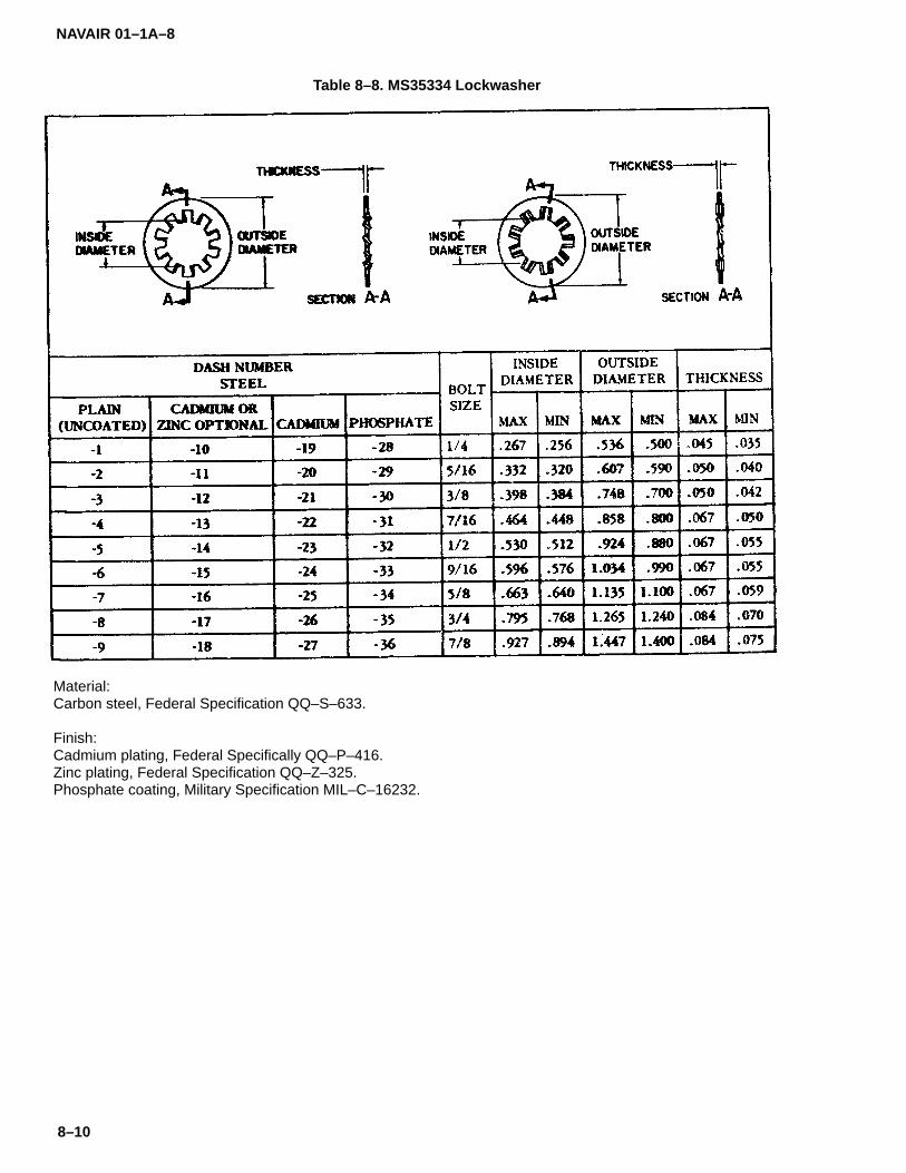
NAVAIR 01–1A–8
8–10
Table 8–8. MS35334 Lockwasher
Material:Carbon steel, Federal Specification QQ–S–633.
Finish:Cadmium plating, Federal Specifically QQ–P–416.Zinc plating, Federal Specification QQ–Z–325.Phosphate coating, Military Specification MIL–C–16232.

NAVAIR 01–1A–8
8–11
Table 8–9. MS35335 Lockwasher
Material:Carbon steel, Federal Specification QQ–S–633.Corrosion–resistant steel Federal Standard Number 66.Phosphor bronze, Federal Specification QQ–P–330.
Finish:Cadmium plating, Federal Specification QQ–P–416.Zinc plating, Federal Specification QQ–Z–325.Phosphate coating, Military Specification MIL–C–16232.Tin plating, Military Specification MIL–T–10727.

NA
VAIR
01–1A–8
8–12
Table 8–10. M
S35336 L
ockw
asher

NAVAIR 01–1A–8
8–13
Table 8–11. MS35338 Lockwasher
Material:Carbon steel, Federal Specification QQ–S–633.Corrosion–resistant steel, Federal Standard Number 66.Phosphor bronze, Federal Specification QQ–P–330.Nickel copper alloy, Federal Specification QQ–N–286.
Finish:Cadmium plating, Federal Specification QQ–P–416.Zinc plating, Federal Specification QQ–Z–325.Phosphate coating, Military Specification MIL–C–16232.

NAVAIR 01–1A–8
8–14
Table 8–12. MS35340 Lockwasher
Material:Carbon steel, Federal Specification QQ–S–633.
Finish:Zinc plating, Federal Specification QQ–Z–325.Phosphate coating, Military Specification MIL–C–16232.Cadmium plating, Federal Specification QQ–P–416.
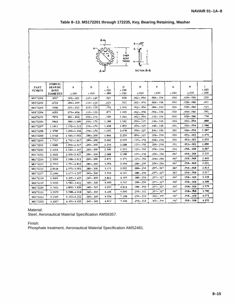
NAVAIR 01–1A–8
8–15
Table 8–13. MS172201 through 172235, Key, Bearing Retaining, Washer
Material:Steel, Aeronautical Material Specification AMS6357.
Finish:Phosphate treatment, Aeronautical Material Specification AMS2481.
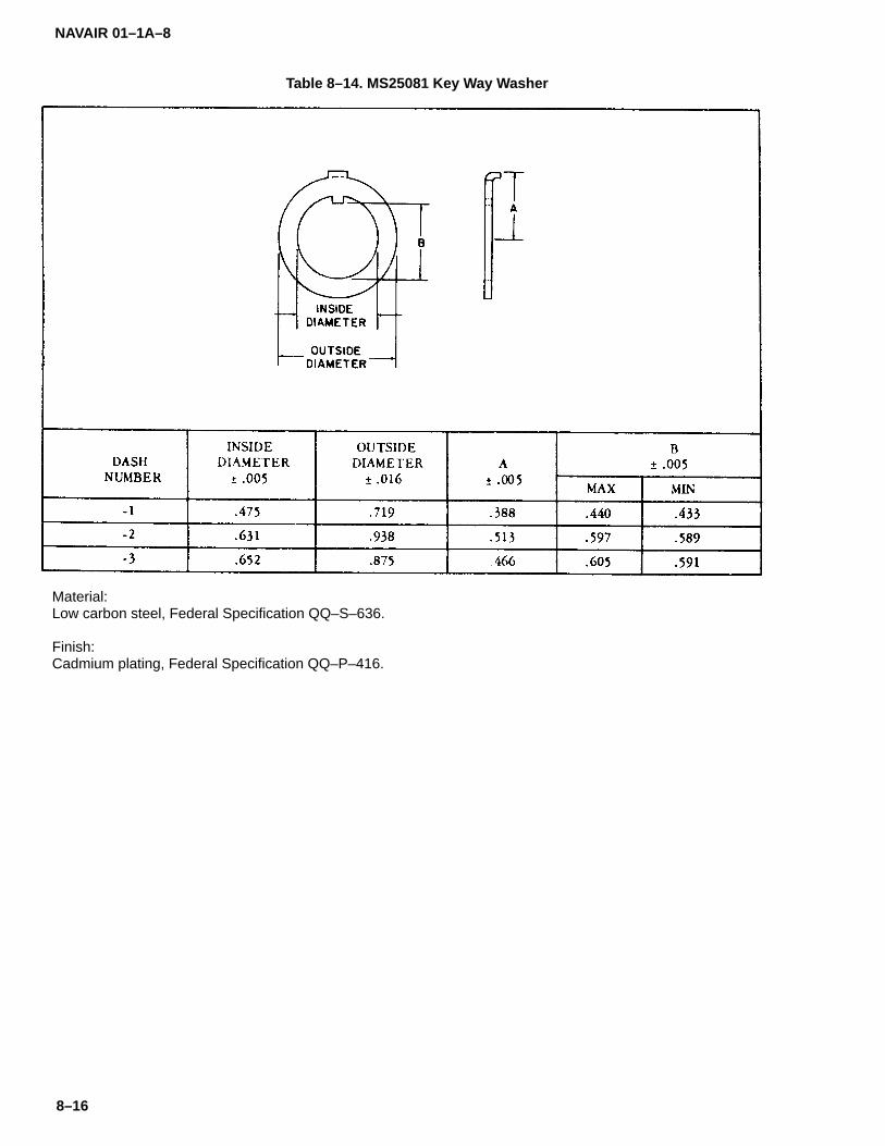
NAVAIR 01–1A–8
8–16
Table 8–14. MS25081 Key Way Washer
Material:Low carbon steel, Federal Specification QQ–S–636.
Finish:Cadmium plating, Federal Specification QQ–P–416.

NAVAIR 01–1A–8
8–17
Table 8–15. Washer-rod End Locking

NAVAIR 01–1A–8
8–18
Table 8-15. Washer-rod End Locking (Continued)
NAVAIR 01–1A–8
9–1
SECTION IX
PINS
9–1. PINS.
9–2. Taper pins, flathead pins, cotter pins, lock-pinsand spring pins are used in aircraft applications.
9–3. TAPER PINS. Taper pins are used in joints sub-ject to shear loads and in restricted clearanceapplications (refer to Tables 9-1 and 9-2). AN386 drilledtaper pins are used in conjunction with an AN975 taper-pin washer and shear nut. AN386 undrilled taper pinsare used in conjunction with a self-locking nut. Securedrilled taper pins with a cotter pin.
9–4. FLATHEAD PINS. Flathead pins are designedfor use on tie rod terminals or secondary control sys-tems (refer to Tables 9-3 and 9–4). Secure flathead pinswith a cotter pin in such a manner that the head faces up,so if the cotter pin fails or works out, the pin will remainin place.
9–5. COTTER PINS. Cotter pins are designed foruse with bolts, screws, nuts, and pins in applicationswhere such securing is required. Cotter pins are madefrom carbon steel, CRES, brass, or nickel-copper alloy(refer to Table 9-5). Common points are the extendedprong, square (plain) cut, and hammer lock per
MS24665. Use the largest diameter cotter pin which fitsconsistently with the diameter of the cotter pin hole and/or slots in the nut. Cotter pins shall not be reused. Referto Tables 9–6 through 9–10 for data on cotter pinlengths.
9–6. LOCKPINS. Refer to Tables 9-11 and 9-12 fordata on lockpins.
9–7. SPRING PINS. Spring pins are slotted, cham-fered pins designed for use in double shear applications(refer to Tables 9-13 through 9-16). They have a largerdiameter than the hole and are compressed wheninstalled (see Figure 9-1). Spring pins require no othermeans of securing and may be used inside one anotherto increase shear strength. Spring pins shall not be usedin applications where loss or failure of the pin may en-danger safety of flight. They shall be used in primarystructural applications only where there is no rotation orrelative movement of the parts. Spring pins may be re-used if the hole has not been enlarged or deformed.CRES spring pins shall not be used in applications sub-ject to temperatures exceeding 700�F. Non-CRESspring pins shall not be used in applications subject totemperatures exceeding 500�F. Do not substitutespring pins for cotter pins.
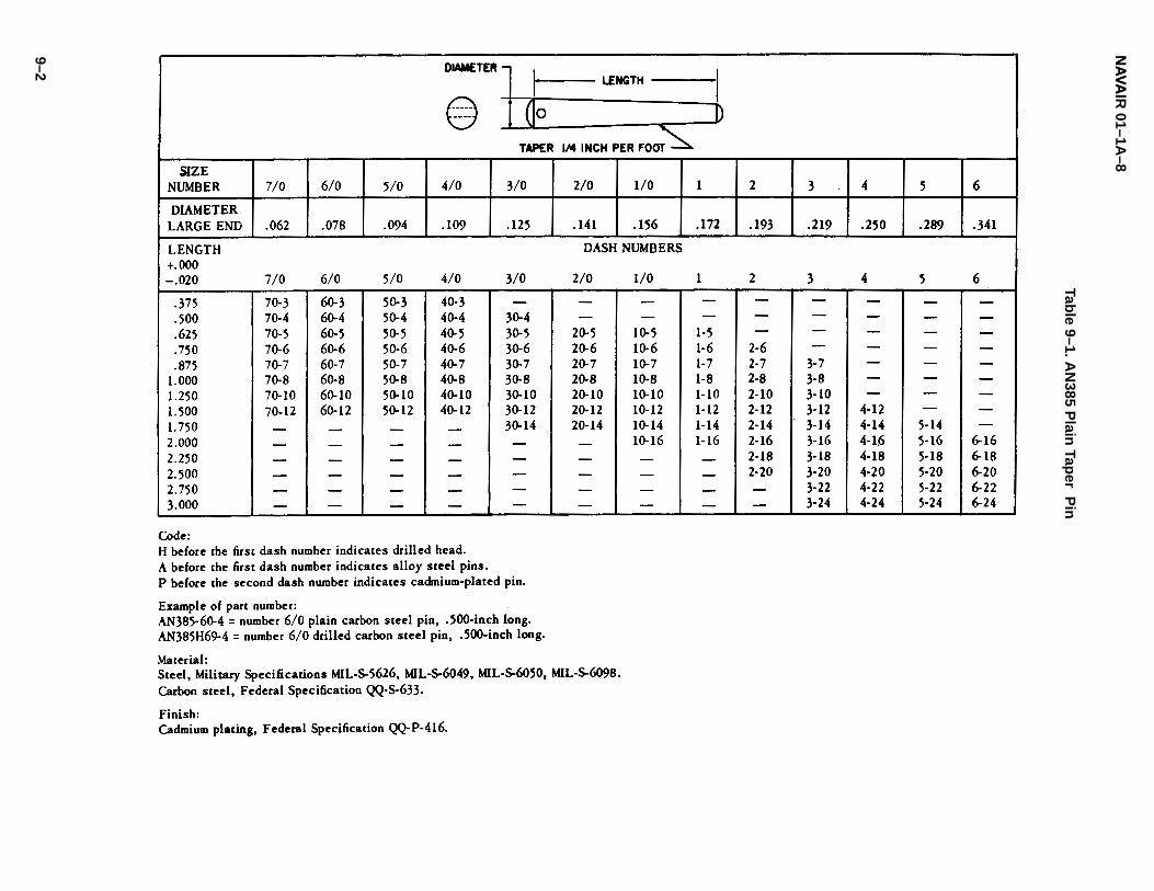
NA
VAI
NA
VAIR
01–1A–8
9–2
Table 9–1. A
N385 P
lain Tap
er Pin
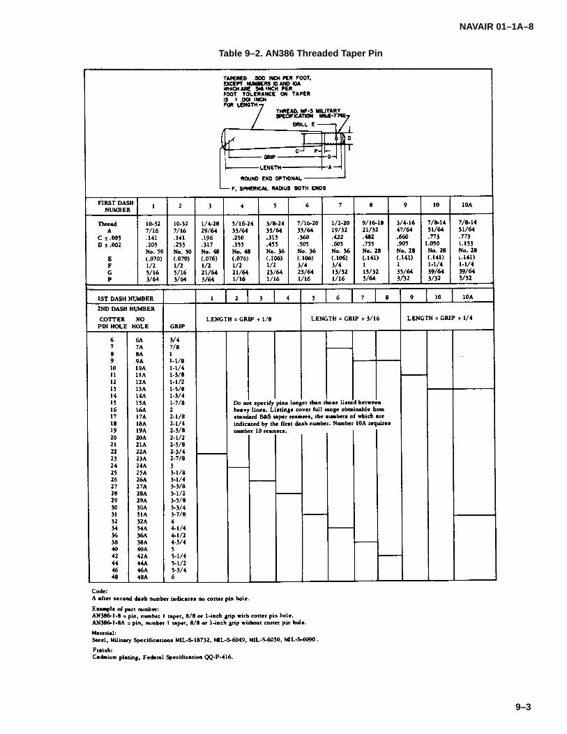
NAVAIR 01–1A–8
9–3
Table 9–2. AN386 Threaded Taper Pin

NAVAINAVAIR 01–1A–8
9–4
Table 9–3. AN392 Through AN406, Flathead Pins

NAVAIR 01–1A–8
9–5
Table 9–4. Flathead Pins

NAVAINAVAIR 01–1A–8
9–6
Table 9-4. Flathead Pins (Continued)

NAVAIR 01–1A–8
9–7
Table 9–4. Flathead Pins (Continued)

NAVAINAVAIR 01–1A–8
9–8
Table 9-4. Flathead Pins (Continued)
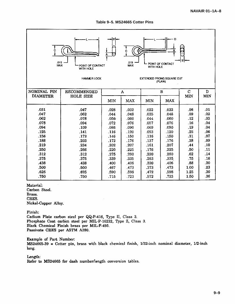
NAVAIR 01–1A–8
9–9
Table 9–5. MS24665 Cotter Pins
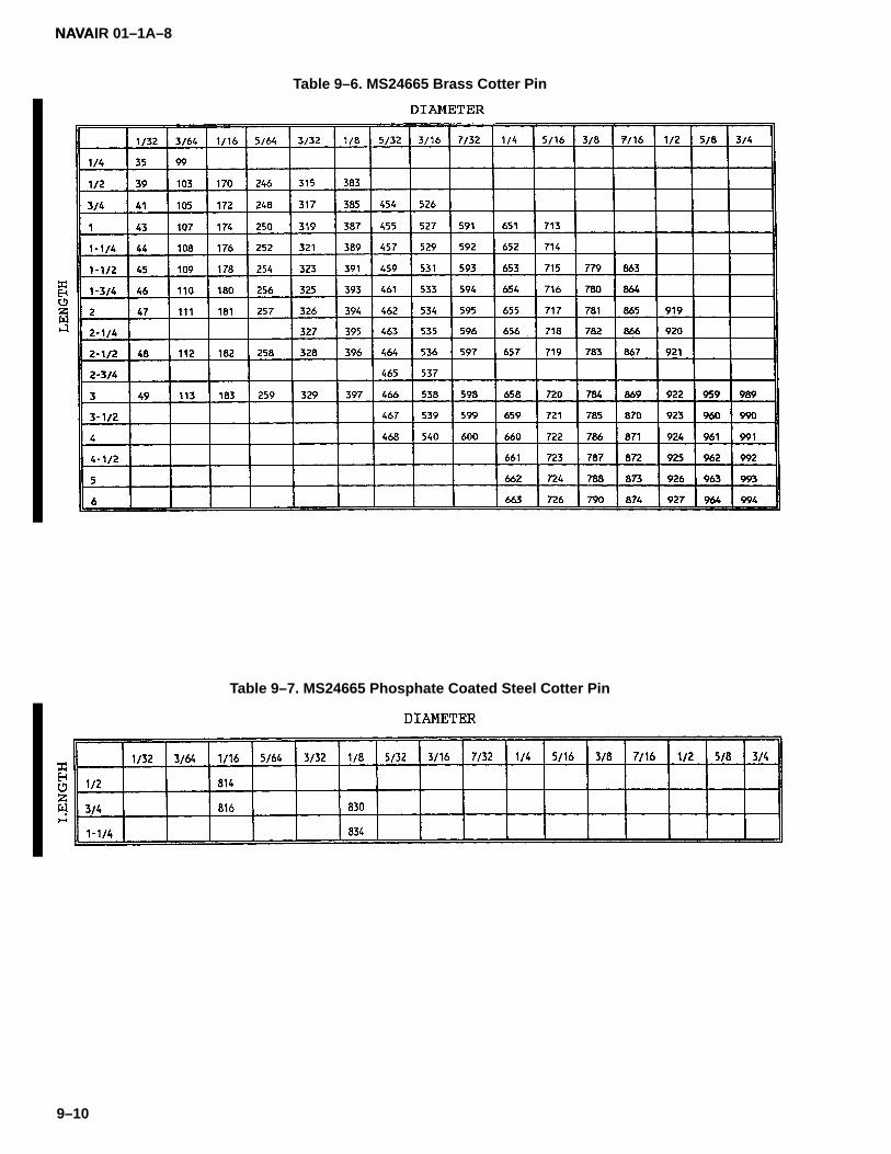
NAVAINAVAIR 01–1A–8
9–10
Table 9–6. MS24665 Brass Cotter Pin
Table 9–7. MS24665 Phosphate Coated Steel Cotter Pin
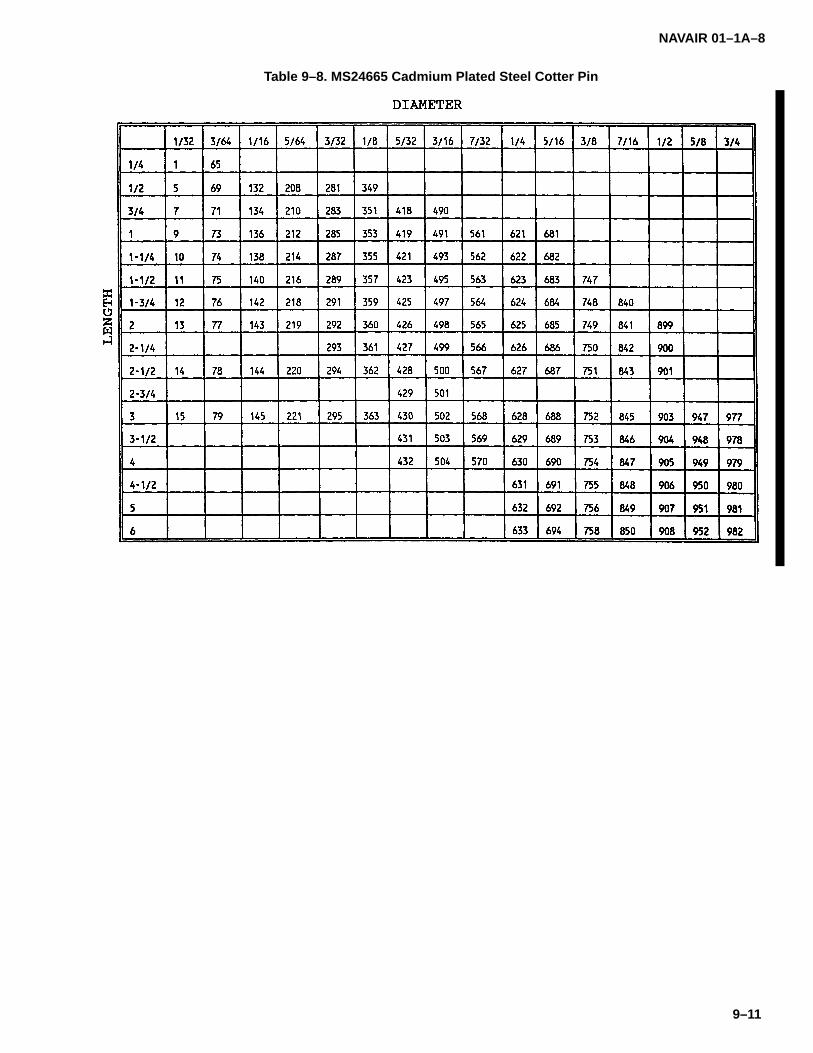
NAVAIR 01–1A–8
9–11
Table 9–8. MS24665 Cadmium Plated Steel Cotter Pin
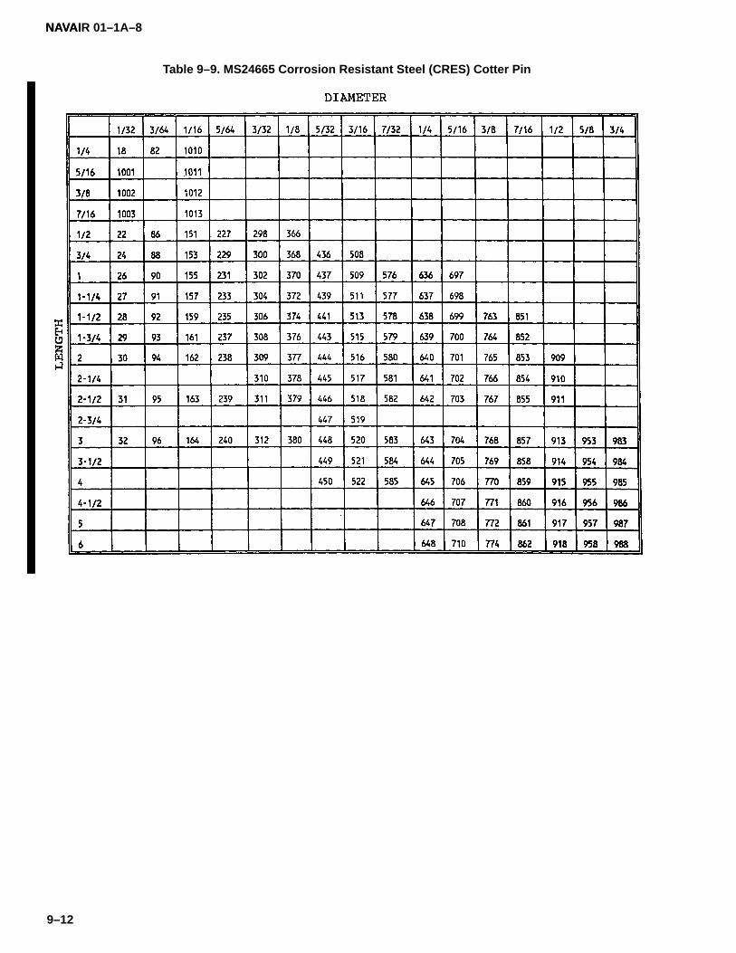
NAVAINAVAIR 01–1A–8
9–12
Table 9–9. MS24665 Corrosion Resistant Steel (CRES) Cotter Pin

NAVAIR 01–1A–8
9–13
Table 9–10. MS24665 Nickel–Copper Alloy Cotter Pin

NAVAINAVAIR 01–1A–8
9–14
Table 9–11. AN150201 Through AN150300, Lockpins
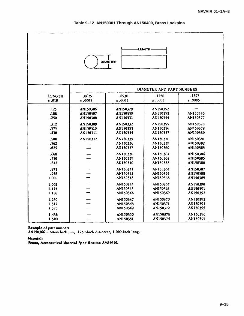
NAVAIR 01–1A–8
9–15
Table 9–12. AN150301 Through AN150400, Brass Lockpins

NA
VAI
NA
VAIR
01–1A–8
9–16
Table 9–13. M
S9047 P
ho
sph
ate Fin
ish S
teel Sp
ring
Pin

NA
VAIR
01–1A–8
9–17
Table 9–14. M
S9048 C
adm
ium
–Plated
Steel S
prin
g P
in

NA
VAI
NA
VAIR
01–1A–8
9–18
Table 9–15. M
S171401 T
hro
ug
h M
S171900, S
prin
g P
ins

NAVAIR 01–1A–8
9–19
Table 9–16. NAS561 Heavy Duty Spring Pin

NAVAINAVAIR 01–1A–8
9–20
Figure 9–1. Removing and Replacing Spring Pin
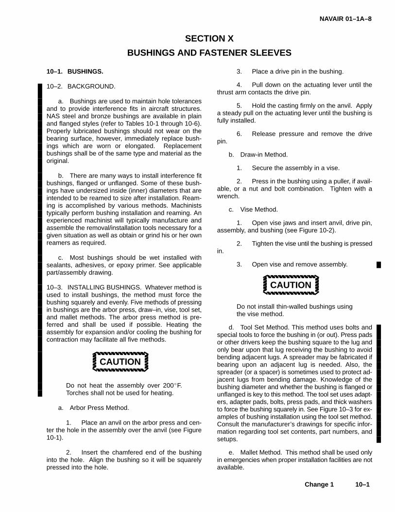
NAVAIR 01–1A–8
Change 1 10–1
SECTION X
BUSHINGS AND FASTENER SLEEVES
10–1. BUSHINGS.
10–2. BACKGROUND.
a. Bushings are used to maintain hole tolerancesand to provide interference fits in aircraft structures.NAS steel and bronze bushings are available in plainand flanged styles (refer to Tables 10-1 through 10-6).Properly lubricated bushings should not wear on thebearing surface, however, immediately replace bush-ings which are worn or elongated. Replacementbushings shall be of the same type and material as theoriginal.
b. There are many ways to install interference fitbushings, flanged or unflanged. Some of these bush-ings have undersized inside (inner) diameters that areintended to be reamed to size after installation. Ream-ing is accomplished by various methods. Machiniststypically perform bushing installation and reaming. Anexperienced machinist will typically manufacture andassemble the removal/installation tools necessary for agiven situation as well as obtain or grind his or her ownreamers as required.
c. Most bushings should be wet installed withsealants, adhesives, or epoxy primer. See applicablepart/assembly drawing.
10–3. INSTALLING BUSHINGS. Whatever method isused to install bushings, the method must force thebushing squarely and evenly. Five methods of pressingin bushings are the arbor press, draw–in, vise, tool set,and mallet methods. The arbor press method is pre-ferred and shall be used if possible. Heating theassembly for expansion and/or cooling the bushing forcontraction may facilitate all five methods.
CAUTION
Do not heat the assembly over 200�F.Torches shall not be used for heating.
a. Arbor Press Method.
1. Place an anvil on the arbor press and cen-ter the hole in the assembly over the anvil (see Figure10-1).
2. Insert the chamfered end of the bushinginto the hole. Align the bushing so it will be squarelypressed into the hole.
3. Place a drive pin in the bushing.
4. Pull down on the actuating lever until thethrust arm contacts the drive pin.
5. Hold the casting firmly on the anvil. Applya steady pull on the actuating lever until the bushing isfully installed.
6. Release pressure and remove the drivepin.
b. Draw-in Method.
1. Secure the assembly in a vise.
2. Press in the bushing using a puller, if avail-able, or a nut and bolt combination. Tighten with awrench.
c. Vise Method.
1. Open vise jaws and insert anvil, drive pin,assembly, and bushing (see Figure 10-2).
2. Tighten the vise until the bushing is pressedin.
3. Open vise and remove assembly.
CAUTION
Do not install thin-walled bushings usingthe vise method.
d. Tool Set Method. This method uses bolts andspecial tools to force the bushing in (or out). Press padsor other drivers keep the bushing square to the lug andonly bear upon that lug receiving the bushing to avoidbending adjacent lugs. A spreader may be fabricated ifbearing upon an adjacent lug is needed. Also, thespreader (or a spacer) is sometimes used to protect ad-jacent lugs from bending damage. Knowledge of thebushing diameter and whether the bushing is flanged orunflanged is key to this method. The tool set uses adapt-ers, adapter pads, bolts, press pads, and thick washersto force the bushing squarely in. See Figure 10–3 for ex-amples of bushing installation using the tool set method.Consult the manufacturer’s drawings for specific infor-mation regarding tool set contents, part numbers, andsetups.
e. Mallet Method. This method shall be used onlyin emergencies when proper installation facilities are notavailable.
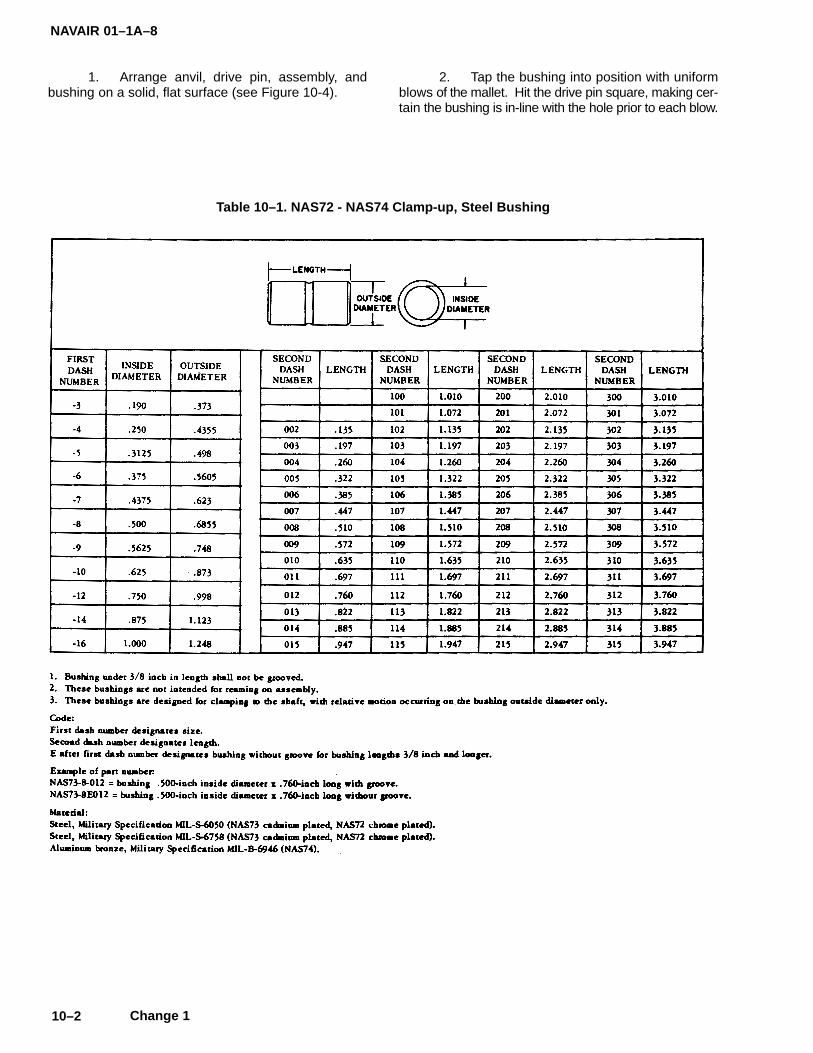
NAVAIR 01–1A–8
10–2 Change 1
1. Arrange anvil, drive pin, assembly, andbushing on a solid, flat surface (see Figure 10-4).
2. Tap the bushing into position with uniformblows of the mallet. Hit the drive pin square, making cer-tain the bushing is in-line with the hole prior to each blow.
Table 10–1. NAS72 - NAS74 Clamp-up, Steel Bushing
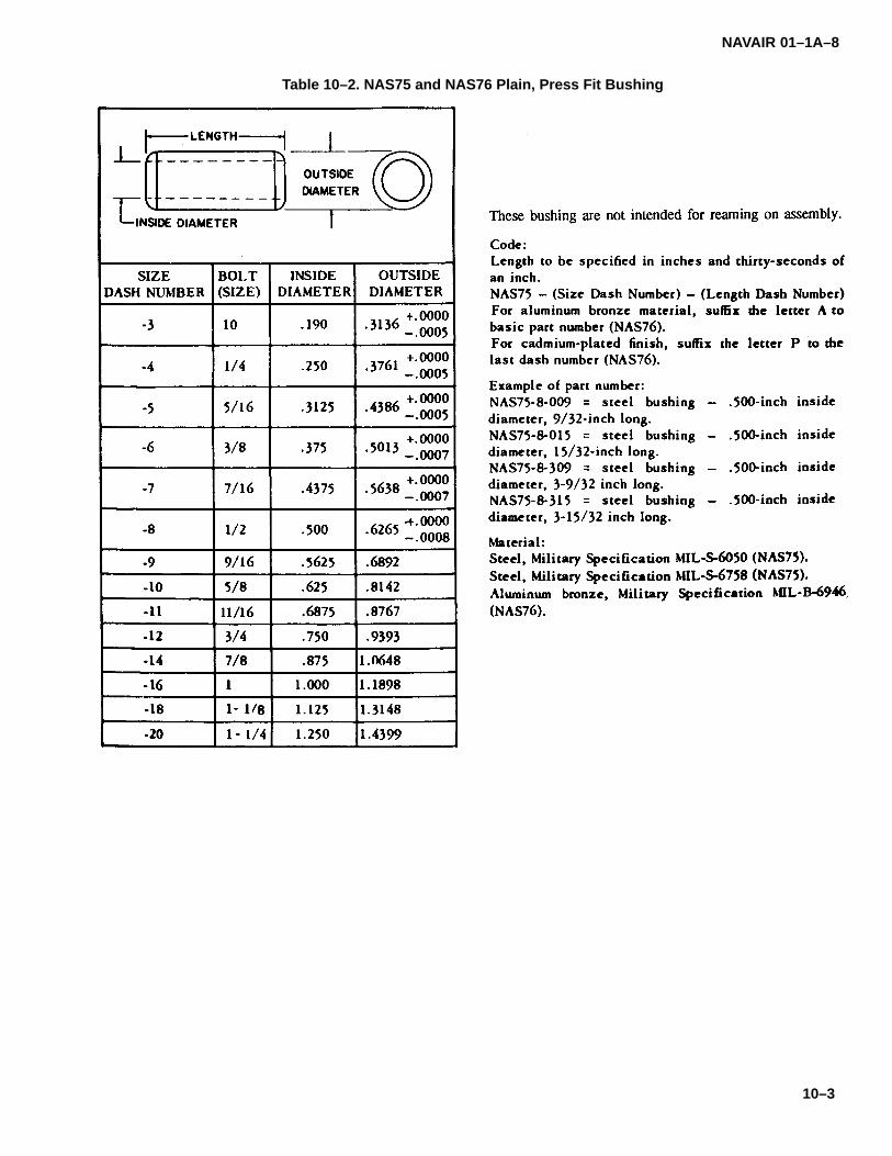
NAVAIR 01–1A–8
10–3
Table 10–2. NAS75 and NAS76 Plain, Press Fit Bushing
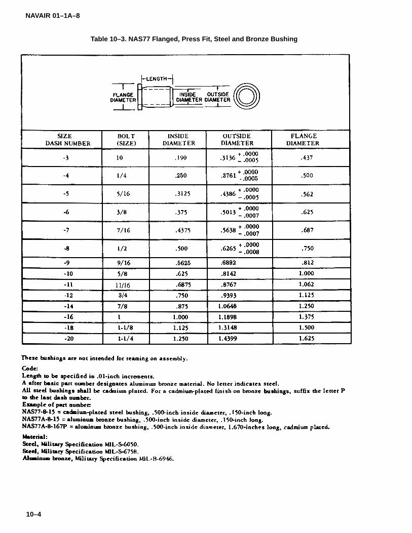
NAVAIR 01–1A–8
10–4
Table 10–3. NAS77 Flanged, Press Fit, Steel and Bronze Bushing
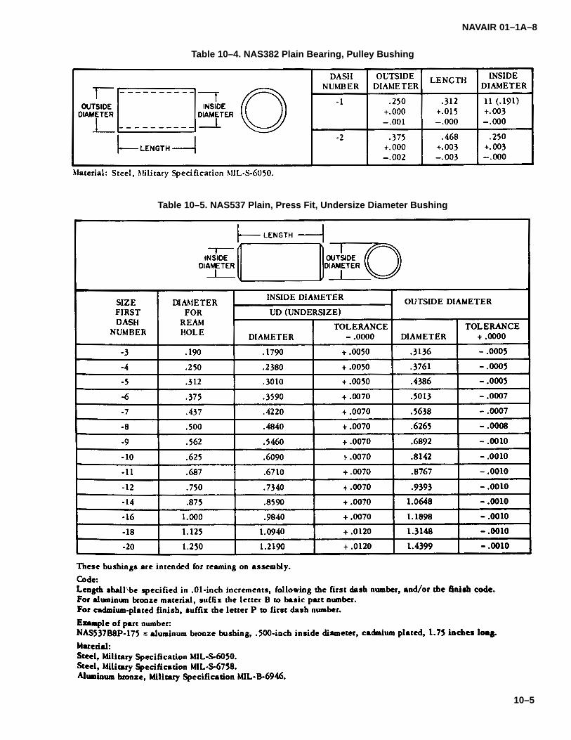
NAVAIR 01–1A–8
10–5
Table 10–4. NAS382 Plain Bearing, Pulley Bushing
Table 10–5. NAS537 Plain, Press Fit, Undersize Diameter Bushing

NAVAIR 01–1A–8
10–6
Table 10–6. NAS538 Flanged, Press Fit, Undersize Inside Diameter Bushing
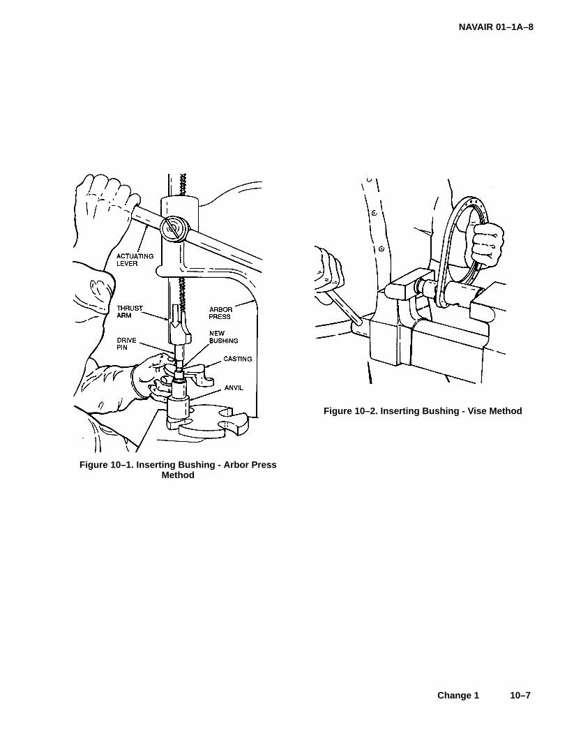
NAVAIR 01–1A–8
Change 1 10–7
Figure 10–1. Inserting Bushing - Arbor PressMethod
Figure 10–2. Inserting Bushing - Vise Method

NAVAIR 01–1A–8
10–8 Change 1
Figure 10–3. Examples of Bushing Installation and Removal Using Tool Set Method (Sheet 1 of 2)
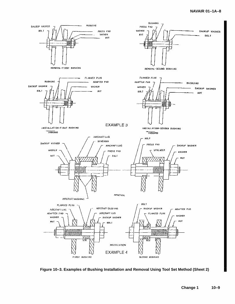
NAVAIR 01–1A–8
Change 1 10–9
Figure 10–3. Examples of Bushing Installation and Removal Using Tool Set Method (Sheet 2)
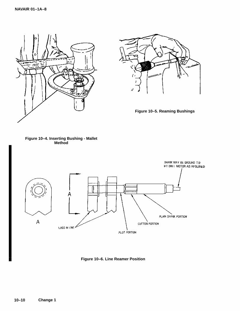
NAVAIR 01–1A–8
10–10 Change 1
Figure 10–4. Inserting Bushing - MalletMethod
Figure 10–5. Reaming Bushings
Figure 10–6. Line Reamer Position

NAVAIR 01–1A–8
Change 1 10–11
10–4. REAMING HOLES FOR BUSHINGS.
a. When bushing alignment is critical, line reamingwith a machine is recommended. If necessary, as withinstalled bushings that have improper tolerances, handreaming may be performed as follows:
1. Secure the assembly in a vise. Insert theproper size reamer into a driving tool (see Figure 10-5).
2. Keep the reamer in–line with the hole in theassembly and ream to the dimension applicable for thebushing.
b. Some bushings are intended to be reamed afterinstallation. Typically, a single lug bushing could bereamed using an unpiloted reamer with a guide block, apiloted reamer (also used for line reaming), or a handreamer. A hand reamer is slightly tapered up to the re-quired size and is turned with a wrench via a square onthe end.
c. Line reaming is typically performed when multi-ple lugs are involved. It requires a reamer that starts witha non–cutting pilot part. The pilot part shall be longenough to slip through multiple bushings to establish theline before the cutter part of the reamer starts cutting.Furthermore, the long pilot shall closely fit through allundersized bushing bores before cutting actually starts.The cutting part of the piloted reamer should be 0.5 to1.0 inch long and shall transform to plain shank whilemaintaining the same diameter. Reamers typicallyshould be sized to cut ten thousandths of an inch(0.010�) of material on the diameter in a single pass.Reamers usually cut about one thousandths of an inch(0.001�) larger than they measure. Sometimes, tape isused to “shim” the pilot diameter to achieve the close fit.If a significant amount of material must be removed, aseries of progressively larger reamers is required. Thereamer may be resharpened as long as it still cuts withinspecification. Reamers cut smaller as they are used andsharpened (see Figure 10–6).
10–5. REMOVING BUSHINGS. Whatever method isused to remove and install bushings, the method mustforce the bushing squarely and evenly. Worn or dam-aged bushings shall be removed using either an arborpress fitted with a support plate with various sized open-ings, or using a tool set including bolts and special tools.
a. Arbor Press Method.
1. Place the bushed assembly over an ap-propriate sized opening of the support plate (see Figure10–7).
NOTEWhen removing plain, symmetrical bush-ings that extend through the assembly,the driving force may be applied from ei-ther side. On flanged bushings, place theflange opposite the driving force.
2. Place drive pin on bushing. The shoulder ofthe drive pin shall be smaller than the hole in the assem-bly, but larger than the hole in the bushing. The pilot onthe drive pin shall be large enough to keep the shouldercentered on the bushing.
3. Hold the assembly firmly with one hand andlower the actuating lever until the thrust arm contacts thedrive pin (see Figure 10–8). Continue pulling on the ac-tuating lever until the bushing is forced out of theassembly.
b. Tool Set Method. This method uses bolts andspecial tools to force the bushing out. Press pads or oth-er drivers keep the bushing square to the lug and onlybear upon that lug receiving the bushing to avoid bend-ing adjacent lugs. A spreader may be fabricated ifbearing upon an adjacent lug is needed. Also, thespreader (or a spacer) is sometimes used to protect ad-jacent lugs from bending damage. Knowledge of thebushing diameter and whether the bushing is flanged orunflanged is key to this method. The tool set uses adapt-ers, adapter pads, bolts, press pads, and thick washersto force the bushing squarely in. See Figure 10–3 for ex-amples of bushing removal using the tool set method.Consult the manufacturer’s drawings for specific infor-mation regarding tool set contents, part numbers, andsetups.
10–6. FASTENER SLEEVES.
10–7. Fastener sleeves are used to repair enlarged,elongated, or corroded fastener holes in structural andnon-structural applications. They may be substituted foroversize fasteners and are designed for use with stan-dard diameter fasteners. 1/64 and 1/32-inch oversizefastener sleeves are manufactured from A286 stainlesssteel in standard fastener diameters (see Table 10-7 forhead styles and MS numbers). Fastener sleeves aredesigned with grooves spaced 1/16-inch apart on theshank. The grooves serve two purposes: (1) to trapsealant between the sleeve and the wall of the hole toafford better seals, and (2) to facilitate adjustment ofsleeve length.
10–8. INSTALLATION OF FASTENER SLEEVES.Use the following procedure for installation of fastenersleeves:
a. Sleeve Selection. Select the appropriate sizeand type sleeve for a shear or tension application. Di-ameters #10 through 3/8-inch are available in 1-inchlength; others are available in 3/4-inch length.
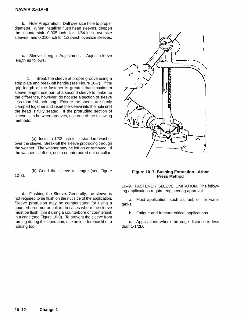
NAVAIR 01–1A–8
10–12 Change 1
b. Hole Preparation. Drill oversize hole to properdiameter. When installing flush head sleeves, deepenthe countersink 0.005-inch for 1/64-inch oversizesleeves, and 0.010-inch for 1/32-inch oversize sleeves.
c. Sleeve Length Adjustment. Adjust sleevelength as follows:
1. Break the sleeve at proper groove using astep plate and break-off handle (see Figure 10-7). If thegrip length of the fastener is greater than maximumsleeve length, use part of a second sleeve to make upthe difference, however, do not use a section of sleeveless than 1/4-inch long. Ensure the sheets are firmlyclamped together and insert the sleeve into the hole untilthe head is fully seated. If the protruding section ofsleeve is in between grooves, use one of the followingmethods:
(a) Install a 1/32-inch thick standard washerover the sleeve. Break-off the sleeve protruding throughthe washer. The washer may be left on or removed. Ifthe washer is left on, use a counterbored nut or collar.
(b) Grind the sleeve to length (see Figure10-8).
d. Flushing the Sleeve. Generally, the sleeve isnot required to be flush on the nut side of the application.Sleeve protrusion may be compensated for using acounterbored nut or collar. In cases where the sleevemust be flush, trim it using a counterbore or countersinkin a cage (see Figure 10-9). To prevent the sleeve fromturning during this operation, use an interference fit or aholding tool.
Figure 10–7. Bushing Extraction - ArborPress Method
10–9. FASTENER SLEEVE LIMITATION. The follow-ing applications require engineering approval:
a. Fluid application, such as fuel, oil, or watertanks.
b. Fatigue and fracture critical applications.
c. Applications where the edge distance is lessthan 1-1/2D.
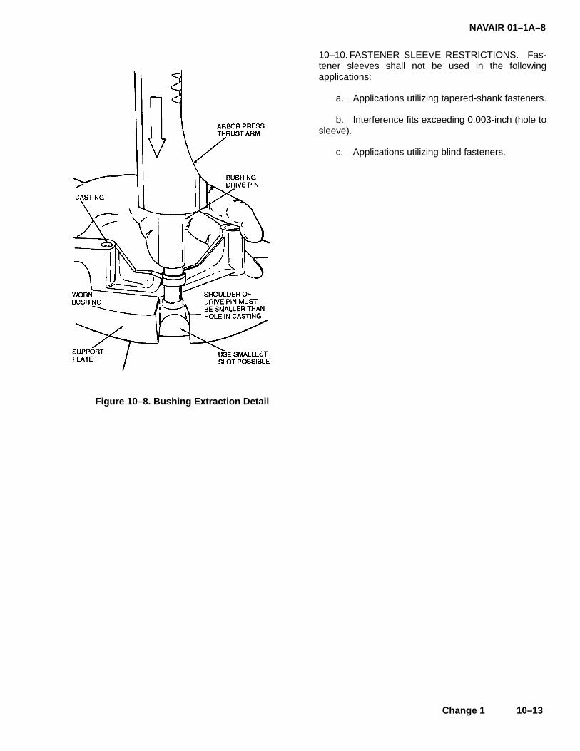
NAVAIR 01–1A–8
Change 1 10–13
Figure 10–8. Bushing Extraction Detail
10–10. FASTENER SLEEVE RESTRICTIONS. Fas-tener sleeves shall not be used in the followingapplications:
a. Applications utilizing tapered-shank fasteners.
b. Interference fits exceeding 0.003-inch (hole tosleeve).
c. Applications utilizing blind fasteners.

NAVAIR 01–1A–8
10–14 Change 1
Table 10–7. Fastener Sleeve Styles
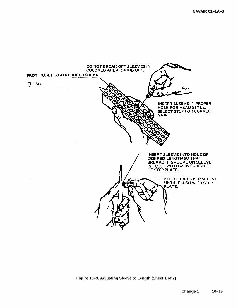
NAVAIR 01–1A–8
Change 1 10–15
Figure 10–9. Adjusting Sleeve to Length (Sheet 1 of 2)

NAVAIR 01–1A–8
10–16 Change 1
Figure 10-9. Adjusting Sleeve to Length (Sheet 2 of 2)

NAVAIR 01–1A–8
Change 1 10–17/(10–18 blank)
Figure 10–10. Bonding Sleeve Figure 10–11. Grinding Sleeve to Proper Length

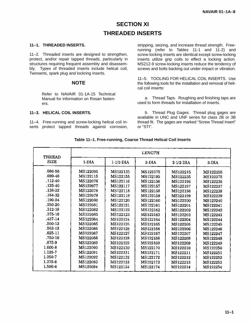
NAVAIR 01–1A–8
11–1
SECTION XI
THREADED INSERTS
11–1. THREADED INSERTS.
11–2. Threaded inserts are designed to strengthen,protect, and/or repair tapped threads, particularly instructures requiring frequent assembly and disassem-bly. Types of threaded inserts include helical coil,Twinserts, spark plug and lockring inserts.
NOTE
Refer to NAVAIR 01-1A-15 TechnicalManual for information on Rosan fasten-ers.
11–3. HELICAL COIL INSERTS.
11–4. Free-running and screw-locking helical coil in-serts protect tapped threads against corrosion,
stripping, seizing, and increase thread strength. Free-running (refer to Tables 11-1 and 11-2) andscrew-locking inserts are identical except screw-lockinginserts utilize grip coils to effect a locking action.MS212-9 screw-locking inserts reduce the tendency ofscrews and bolts backing out under impact or vibration.
11–5. TOOLING FOR HELICAL COIL INSERTS. Usethe following tools for the installation and removal of heli-cal coil inserts:
a. Thread Taps. Roughing and finishing taps areused to form threads for installation of inserts.
b. Thread Plug Gages. Thread plug gages areavailable in UNC and UNF series for class 2B or 3Bthread fit. The gages are marked “Screw Thread Insert”or “STI”.
Table 11–1. Free-running, Coarse Thread Helical Coil Inserts

NAVAIR 01–1A–8
11–2
Table 11–2. Free Running, Fine Thread Helical Coil Inserts
c. Inserting Tools. The following are types of in-serting tools:
1. Threaded Mandrel Prewinder. Class 1,Style A inserting tools install 1/2-inch and smaller UNCand UNF thread series inserts (see Figure 11-1).Thread mandrel through insert until one full thread pro-trudes. Position the tool squarely against the tappedhole and thread insert to desired depth. Adjust depth us-ing depth control stop collar. Rotate mandrelcounterclockwise for retraction.
2. Threaded Non-captive Mandrel Prewinder.Class 1, Style B inserting tools install 9/16-inch through1-1/2-inch UNF thread series inserts (see Figure 11-2).Adjust depth by loosening setscrew. Place insert onmandrel by removing prewinder body. Thread insert un-til shoulder contacts body. Readjust depth if necessary.
3. Threaded Mandrel. Class 2, Style A insert-ing tools install #2 and #3 UNC thread series inserts.Class 2, Style B inserting tools install 9/16-inch through
1-1/2-inch UNC thread series inserts (see Figure 11-3).Thread insert onto the mandrel, position tool squarelyagainst the hole, and thread insert to desired depth.
d. Tang Break-off Tools. The following are types oftang break-off tools (see Figure 11-4):
1. Automatic Punch. Class 1, Style A tangbreak-off tools remove drive tangs from inserts up to1/4-inch. Class 1, Style B tang break-off tools removedrive tangs from 5/16-inch to 1/2-inch inserts. Automat-ic break-off tools consist of a spring actuated punchinside a sleeve with a rubber or plastic tip to preventdamage to the insert.
2. Plain Punch. Class 3 tang break-off toolsremove drive tangs from inserts up to 1/2-inch.
e. Extracting Tools. Extracting tools consist of around shaft, a tapered blade, and a “T” handle (see Fig-ure 11-4). Extract inserts by rotating the toolcounterclockwise.
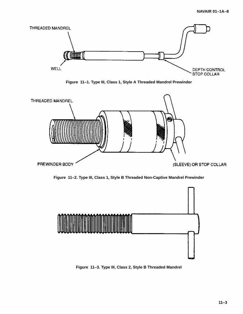
NAVAIR 01–1A–8
11–3
Figure 11–1. Type III, Class 1, Style A Threaded Mandrel Prewinder
Figure 11–2. Type III, Class 1, Style B Threaded Non-Captive Mandrel Prewinder
Figure 11–3. Type III, Class 2, Style B Threaded Mandrel
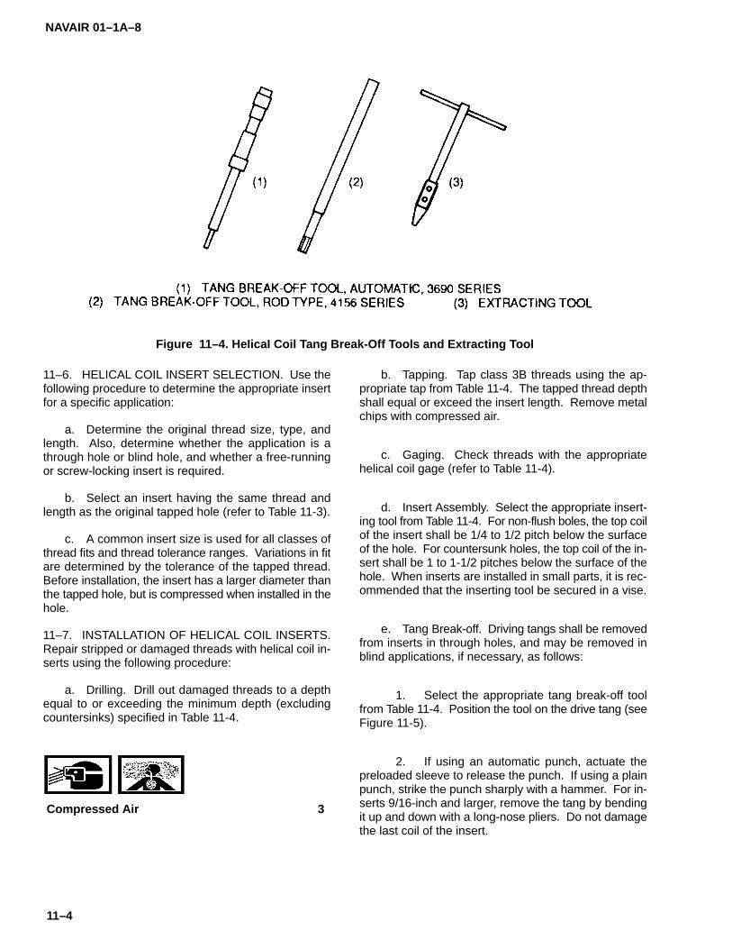
NAVAIR 01–1A–8
11–4
Figure 11–4. HeIicaI Coil Tang Break-Off Tools and Extracting Tool
11–6. HELICAL COIL INSERT SELECTION. Use thefollowing procedure to determine the appropriate insertfor a specific application:
a. Determine the original thread size, type, andlength. Also, determine whether the application is athrough hole or blind hole, and whether a free-runningor screw-locking insert is required.
b. Select an insert having the same thread andlength as the original tapped hole (refer to Table 11-3).
c. A common insert size is used for all classes ofthread fits and thread tolerance ranges. Variations in fitare determined by the tolerance of the tapped thread.Before installation, the insert has a larger diameter thanthe tapped hole, but is compressed when installed in thehole.
11–7. INSTALLATION OF HELICAL COIL INSERTS.Repair stripped or damaged threads with helical coil in-serts using the following procedure:
a. Drilling. Drill out damaged threads to a depthequal to or exceeding the minimum depth (excludingcountersinks) specified in Table 11-4.
Compressed Air 3
b. Tapping. Tap class 3B threads using the ap-propriate tap from Table 11-4. The tapped thread depthshall equal or exceed the insert length. Remove metalchips with compressed air.
c. Gaging. Check threads with the appropriatehelical coil gage (refer to Table 11-4).
d. Insert Assembly. Select the appropriate insert-ing tool from Table 11-4. For non-flush boles, the top coilof the insert shall be 1/4 to 1/2 pitch below the surfaceof the hole. For countersunk holes, the top coil of the in-sert shall be 1 to 1-1/2 pitches below the surface of thehole. When inserts are installed in small parts, it is rec-ommended that the inserting tool be secured in a vise.
e. Tang Break-off. Driving tangs shall be removedfrom inserts in through holes, and may be removed inblind applications, if necessary, as follows:
1. Select the appropriate tang break-off toolfrom Table 11-4. Position the tool on the drive tang (seeFigure 11-5).
2. If using an automatic punch, actuate thepreloaded sleeve to release the punch. If using a plainpunch, strike the punch sharply with a hammer. For in-serts 9/16-inch and larger, remove the tang by bendingit up and down with a long-nose pliers. Do not damagethe last coil of the insert.

NAVAIR 01–1A–8
11–5
Table 11–3. Helical Coil Screw Thread Inserts, Standard and Screw-locking

NA
VAIR
01–1A–8
11–6
Table 11–4. H
eli Co
il Insert Tap
ped
Ho
le and
Too
ling
Data
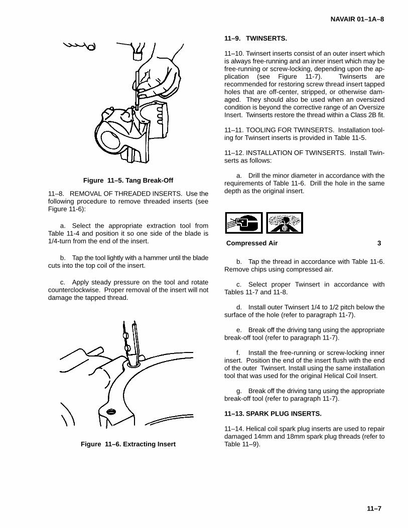
NAVAIR 01–1A–8
11–7
Figure 11–5. Tang Break-Off
11–8. REMOVAL OF THREADED INSERTS. Use thefollowing procedure to remove threaded inserts (seeFigure 11-6):
a. Select the appropriate extraction tool fromTable 11-4 and position it so one side of the blade is1/4-turn from the end of the insert.
b. Tap the tool lightly with a hammer until the bladecuts into the top coil of the insert.
c. Apply steady pressure on the tool and rotatecounterclockwise. Proper removal of the insert will notdamage the tapped thread.
Figure 11–6. Extracting Insert
11–9. TWINSERTS.
11–10. Twinsert inserts consist of an outer insert whichis always free-running and an inner insert which may befree-running or screw-locking, depending upon the ap-plication (see Figure 11-7). Twinserts arerecommended for restoring screw thread insert tappedholes that are off-center, stripped, or otherwise dam-aged. They should also be used when an oversizedcondition is beyond the corrective range of an OversizeInsert. Twinserts restore the thread within a Class 2B fit.
11–11. TOOLING FOR TWINSERTS. Installation tool-ing for Twinsert inserts is provided in Table 11-5.
11–12. INSTALLATION OF TWINSERTS. Install Twin-serts as follows:
a. Drill the minor diameter in accordance with therequirements of Table 11-6. Drill the hole in the samedepth as the original insert.
Compressed Air 3
b. Tap the thread in accordance with Table 11-6.Remove chips using compressed air.
c. Select proper Twinsert in accordance withTables 11-7 and 11-8.
d. Install outer Twinsert 1/4 to 1/2 pitch below thesurface of the hole (refer to paragraph 11-7).
e. Break off the driving tang using the appropriatebreak-off tool (refer to paragraph 11-7).
f. Install the free-running or screw-locking innerinsert. Position the end of the insert flush with the endof the outer Twinsert. Install using the same installationtool that was used for the original Helical Coil Insert.
g. Break off the driving tang using the appropriatebreak-off tool (refer to paragraph 11-7).
11–13. SPARK PLUG INSERTS.
11–14. Helical coil spark plug inserts are used to repairdamaged 14mm and 18mm spark plug threads (refer toTable 11–9).

NAVAIR 01–1A–8
11–8
Figure 11–7. Helical Coil Screw Thread or Screw-Locking Twinsert Assembly
Table 11–5. Twinsert Tool Numbers

NAVAIR 01–1A–8
11–9
Table 11–6. Twinsert Tapped Hole Dimensions

NA
VAIR
01–1A–8
11–10
Table 11–7. H
elical Co
il Screw
Th
read an
d S
crew–lo
cking
Twin
serts–Un
ified C
oarse
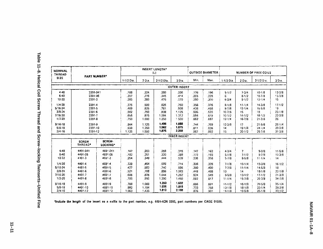
NA
VAIR
01–1A–8
11–11
Table 11–8. H
elical Co
il Screw
Th
read an
d S
crew–lo
cking
Twin
serts–Un
ified F
ine
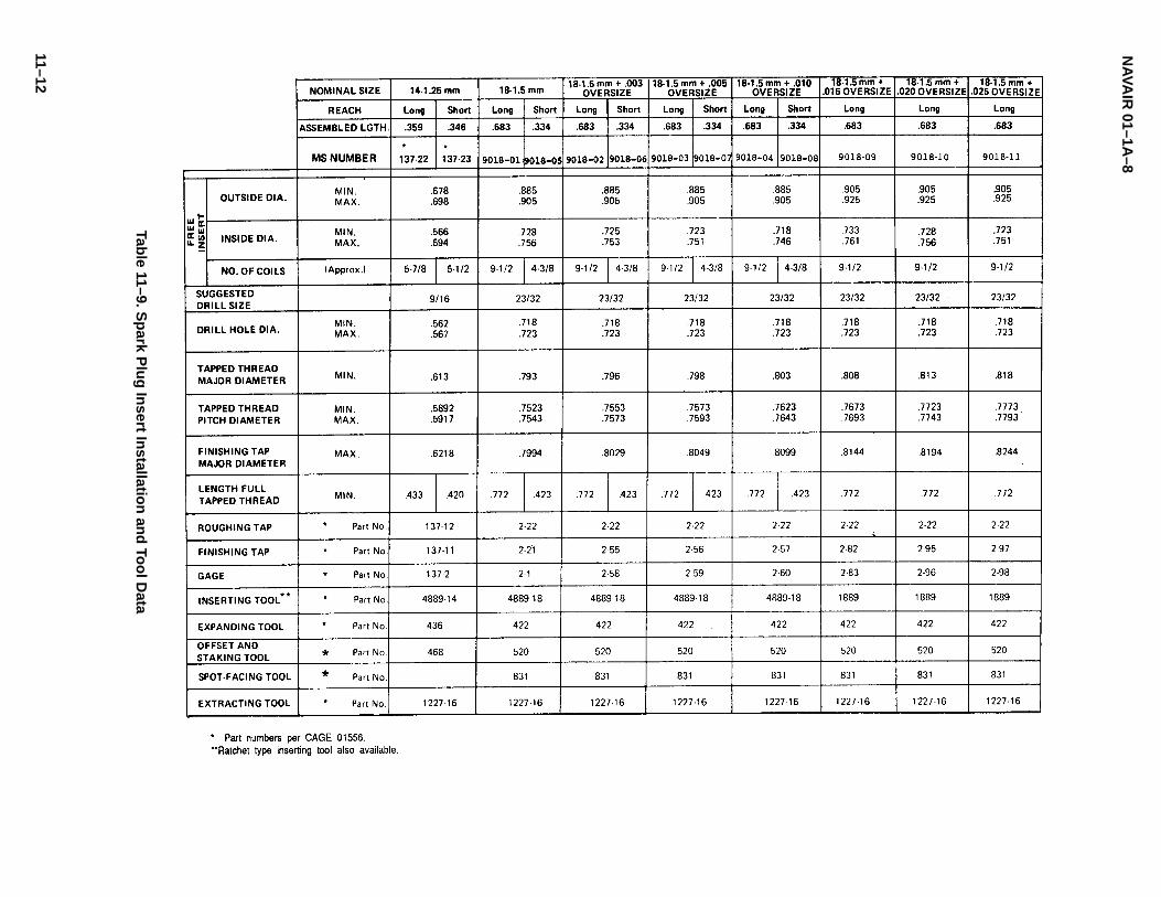
NA
VAIR
01–1A–8
11–12
Table 11–9. S
park P
lug
Insert In
stallation
and
Too
l Data
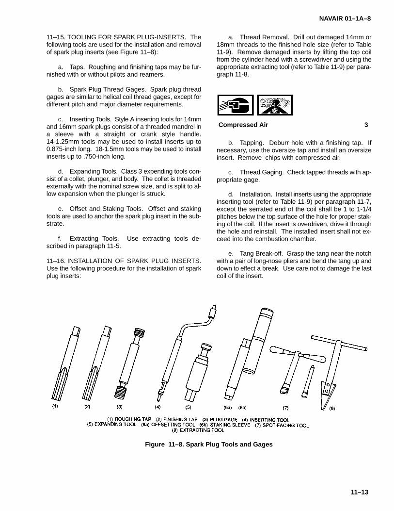
NAVAIR 01–1A–8
11–13
11–15. TOOLING FOR SPARK PLUG-INSERTS. Thefollowing tools are used for the installation and removalof spark plug inserts (see Figure 11–8):
a. Taps. Roughing and finishing taps may be fur-nished with or without pilots and reamers.
b. Spark Plug Thread Gages. Spark plug threadgages are similar to helical coil thread gages, except fordifferent pitch and major diameter requirements.
c. Inserting Tools. Style A inserting tools for 14mmand 16mm spark plugs consist of a threaded mandrel ina sleeve with a straight or crank style handle.14-1.25mm tools may be used to install inserts up to0.875-inch long. 18-1.5mm tools may be used to installinserts up to .750-inch long.
d. Expanding Tools. Class 3 expending tools con-sist of a collet, plunger, and body. The collet is threadedexternally with the nominal screw size, and is split to al-low expansion when the plunger is struck.
e. Offset and Staking Tools. Offset and stakingtools are used to anchor the spark plug insert in the sub-strate.
f. Extracting Tools. Use extracting tools de-scribed in paragraph 11-5.
11–16. INSTALLATION OF SPARK PLUG INSERTS.Use the following procedure for the installation of sparkplug inserts:
a. Thread Removal. Drill out damaged 14mm or18mm threads to the finished hole size (refer to Table11-9). Remove damaged inserts by lifting the top coilfrom the cylinder head with a screwdriver and using theappropriate extracting tool (refer to Table 11-9) per para-graph 11-8.
Compressed Air 3
b. Tapping. Deburr hole with a finishing tap. Ifnecessary, use the oversize tap and install an oversizeinsert. Remove chips with compressed air.
c. Thread Gaging. Check tapped threads with ap-propriate gage.
d. Installation. Install inserts using the appropriateinserting tool (refer to Table 11-9) per paragraph 11-7,except the serrated end of the coil shall be 1 to 1-1/4pitches below the top surface of the hole for proper stak-ing of the coil. If the insert is overdriven, drive it throughthe hole and reinstall. The installed insert shall not ex-ceed into the combustion chamber.
e. Tang Break-off. Grasp the tang near the notchwith a pair of long-nose pliers and bend the tang up anddown to effect a break. Use care not to damage the lastcoil of the insert.
Figure 11–8. Spark Plug Tools and Gages
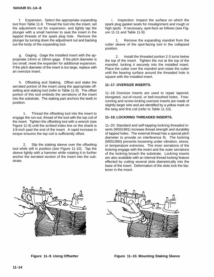
NAVAIR 01–1A–8
11–14
f. Expansion. Select the appropriate expandingtool from Table 11-9. Thread the tool into the insert, setthe adjustment nut for expansion, and lightly tap theplunger with a small hammer to seat the insert in thetapped threads of the spark plug hole. Remove theplunger by turning down the adjustment nut and backingout the body of the expanding tool.
g. Gaging. Gage the installed insert with the ap-propriate 14mm or 18mm gage. If the pitch diameter istoo small, reset the expander for additional expansion.If the pitch diameter of the insert is too large, replace withan oversize insert.
h. Offsetting and Staking. Offset and stake theserrated portion of the insert using the appropriate off-setting and staking tool (refer to Table 11-9). The offsetportion of this tool embeds the serrations of the insertinto the substrate. The staking part anchors the teeth inposition.
1. Thread the offsetting tool into the insert toengage the run-out, thread of the tool with the top coil ofthe insert. Tighten the offsetting tool with a wrench (seeFigure 11-9) until the scribed index line on the shank is1/4-inch past the end of the insert. A rapid increase intorque ensures the top coil is sufficiently offset.
2. Slip the staking sleeve over the offsettingtool while still in position (see Figure 11-10). Tap thesleeve lightly with a hammer while rotating it to furtheranchor the serrated section of the insert into the sub-strate.
Figure 11–9. Using Offsetter
i. Inspection. Inspect the surface on which thespark plug gasket seats for misalignment and rough orhigh spots. If necessary, spot-face as follows (see Fig-ure 11-11 and Table 11-9):
1. Remove the expanding mandrel from thecutter sleeve of the spot-facing tool in the collapsedposition.
2. Install the threaded portion 2-3 turns belowthe top of the insert. Tighten the nut at the top of themandrel, locking it securely into the installed insert.Place the cutter over the mandrel and rotate the cutteruntil the bearing surface around the threaded hole issquare with the installed insert.
11–17. OVERSIZE INSERTS.
11–18. Oversize inserts are used to repair tapered,elongated, out-of-round, or bell-mouthed holes. Free-running and screw-locking oversize inserts are made ofslightly larger wire and are identified by a yellow mark onthe tang and first coil (refer to Table 11-10).
11–19. LOCKRING THREADED INSERTS.
11–20. Standard and self-tapping lockring threaded in-serts (MS51991) increase thread strength and durabilityof tapped holes. The external thread has a special pitchdiameter to provide on interference fit. The lockring(M551990) prevents loosening under vibration, stress,or temperature extremes. The inner serrations of thelockring engage with the insert and the outer serrationsof the lockring broach the substrate. Lockring insertsare also available with an internal thread locking featureeffected by cutting several slots diametrically into thebase of the insert. Deformation of the slots lock the fas-tener in the insert.
Figure 11–10. Mounting Staking Sleeve

NAVAIR 01–1A–8
11–15
Figure 11–11. Spot-Facer
11–21. INSTALLATION OF LOCKRING INSERTS. Usethe following procedure for the installation of lockring in-serts:
a. Drill and counterbore appropriate size hole.
b. Chamfer hole 45� by outside diameter of coun-terbore and tap a class 3 thread. Tapping is not requiredwhen installing self-tapping inserts.
c. Thread insert 0.010-inch to 0.020-inch belowsurface. Insert shall not protrude above the surface.
d. Drive lockring 0.005-inch to 0.010-inch belowsurface. Engage inner serrations of lockring with insertbefore driving.
11–22. REMOVAL OF LOCKRING INSERTS. Use thefollowing procedure for the removal of lockring inserts:
a. Drill through lockring and neck of insert with drillbit of equal size as collar serrations. Do not drill beyonddepth of counterbore.
b. Drive square screw extractor into insert and ap-ply torque.
11–23. THREAD REPAIR KITS.
11–24. Thread repair kits are available in UNC and UNFthread series, spark plug, and oversize threads perMIL-T-213-9. The following are types of thread repairkits:
a. Unified Coarse and Fine Thread Repair Kits.Refer to Table 11-11 for UNC and UNF thread repair kits.
b. Oversize Insert Repair Packs. Oversize insertrepair packs contain special oversize bottoming tapsand standard (free-running) and screwlocking inserts(refer to Table 11-12).
c. Spark Plug Repair Kits. Helical coil spark plugkits are available for repairing damaged or strippedspark plug threads in engine cylinder heads. Serratedspark plug inserts are used exclusively for aircraft en-gine repair (refer to Table 11-13).

NAVAIR 01–1A–8
11–16
Table 11–10. Oversize Screw Thread and Screw-locking Inserts and Taps***

NA
VAIR
01–1A–8
11–17
Table 11–11. T
hread
Rep
air Packs

NAVAIR 01–1A–8
11–18
Table 11–12. Oversize Packs
Table 11–13. Aviation Spark Plug Packs: 14-1.25mm and 18-1.5mm

NAVAIR 01–1A–8
12–1
SECTION XII
SPECIALITY FASTENERS
12–1. SPECIALTY FASTENERS.
12–2. Quick-release pins and fasteners are used to se-cure cowlings, plates, panels, doors, etc. in applicationsrequiring quick and/or frequent removal. Quick-releasefasteners are not designed to carry primary structuralloads. Structural panel fasteners are similar to quick-re-lease fasteners, except they are designed to carrystructural loads.
12–3. QUICK-RELEASE PINS. Quick-release pinsare designed for use in non-structural applicationswhere quick assembly and disassembly is required.They are also used on aircraft landing gear to ensure thegear cannot be retracted while the aircraft is on theground. Quick-release pins are manufactured fromalloy steel or CRES with nominal diameters of 3/16-inchto 1-inch. Grip lengths range from 0.300-inch to9.900-inch (refer to Table 12-1). Single acting quick-re-lease pins require a push on the release button to unlockthe pin. Handles include button (MS17984), “T”(MS17985), and “L” (MS17986) styles (see Figure12-1). Double acting pins (MS17988-MS17990) are re-leased by a push or pull on the release button. Refer toTable 12-1 for hole diameters when installing quick-re-lease pins.
12–4. QUICK-RELEASE AND STRUCTURAL PANELFASTENERS. Quick-release fasteners are used in ap-plications requiring frequent assembly and disassemblyand shall not be subjected to structural loads. Structuralpanel fasteners are designed for use in applicationswhere structural loads are transmitted through the fas-tened joint. Both quick-release and structural panelfasteners provide quick operation, vibration resistance,and increased load-carrying capability. The followingare types of quick-release and structural panel fasten-ers.
a. MS Rotary Quick-operating Fasteners. MSrotary quick-operating fasteners are available in flush(MS17731) and protruding head (MS17732) styles. Useflush head fasteners in exterior applications where aflush surface is desired and protruding head fastenersin interior applications. MS rotary quick-operating fas-teners consist of a 3/8-inch nominal diameter stud andreceptacle (part number MS17731/2-21). The recep-tacle provides a minimum of 0.020-inch axial float.These fasteners are manufactured from cadmium-plated carbon or alloy steel (refer to Table 12-2). SeeFigure 12-2 for determination of grip length. MS quick-operating fasteners shall not be used in applicationssubject to temperatures exceeding 500�F.
b. Quick-release (QR) Structural Panel Fasten-ers. QR structural panel fasteners are high strength,lightweight fasteners conforming to MS17731 andMS17732 (refer to Table 12-3 for part number cross ref-erence). They are designed for use in general aircraftapplications. Refer to Table 12-4 for installation proce-dures.
c. Live Lock Structural Panel Fasteners. LiveLock structural panel fasteners are designed specifical-ly for high performance aircraft and electronicapplications. Live Lock fasteners are available in the fol-lowing series: CA2000 (.1120-40, 2-lead thread),CA1800 (.1640-32, 4-lead thread), and CA1700(.1900-32, 4-lead thread). Stud nuts are available in100� flush, pan, and knurled head styles with hex andslotted recesses (refer to Table 12-5). Refer to Tables12-6 through 12-8 for installation procedures
d. Mark IV Structural Panel Fasteners. Mark IVstructural panel fasteners are designed for use in highperformance aircraft. The Mark IV fastener is designedwith the Patented Flat Beam Lock Nut for increased re-sistance to vibration-induced loosening. Mark IVfasteners are available only with flush head stud bolts:CA2104 series are 1/4-inch and CA2109 are 3/8-inch(refer to Table 12-9). Refer to Table 12-10 for installationprocedures.
e. Paneloc Quarter-turn Fasteners. Panelocquarter-turn fasteners consist of hardened alloy steelstuds and matching, adjustable receptacles. The studsare mounted on a cover or panel by means of split retain-ing rings of spring steel; shear washers can also be usedfor added strength. The standard floating–type recep-tacle is riveted to the structure to which the cover is tobe attached (there are also threaded receptacles forblind mounting in solid castings, forgings, and the like).Paneloc quarter–turn fasteners are available in #10, #1(1/4–inch), and #2 (5/16–inch) sizes. Studs are avail-able in flush, oval, and wing head styles. Standard,floating receptacles are available in two styles: Type Zis a plain receptacle, and Type ZC is a capped or cov-ered receptacle (refer to Table 12–11). Both plain andcapped types are secured to the chassis or panel withtwo rivets. All Paneloc floating–type receptacles offersecure quarter–turn fastening even when studs and re-ceptacle holes are slightly misaligned. Threadedreceptacles in all housings can be adjusted for vari-ances in gasketing materials, sheet thickness and studlengths. Refer to Table 12–12 and the following forinstallation procedures and receptacle adjustments:

NAVAIR 01–1A–8
12–2
1. Inner threaded receptacle adjustmentsmust be made with a special tool to avoid damage. Tofacilitate adjustments on a production basis, specialtools are available from the manufacture.
2. Receptacle adjustments require two steps:
(a) First, position the receptacle 0.050¨ belowthe face of the structure on which the housing ismounted using the Paneloc adjustment tool. (Order ad-justment tools by part number to match the size of thereceptacle. Although the stud ends of these tools are re-placeable, they are not interchangeable).
(b) Second, a fine adjustment is made by en-gaging the mating stud with the receptacle. SincePaneloc receptacle design incorporates automatic studejection to indicate visually an unlocked fastener, it ismandatory when engaging the stud in the receptacle topress the stud downward into the receptacle and seat itwith one quarter turn. For final adjustment, rotate thestud clockwise until the desires tightness between pan-els in achieved. DO NOT EXCEED CLAMPINGLOADS–see Table 12–13).
f. Milson Structural Panel Fasteners. Milsonstructural panel fasteners differ from the other quick-re-lease fasteners in that they utilize a sleeve bolt ratherthan a stud nut. They are available in flush and protrud-ing head styles with several styles of 2-lug and cornerreceptacles (refer to Table 12-14 for Milson panel fas-
tener selection). Refer to Table 12-15 for installationprocedures.
g. Camloc Fasteners. Camloc 4002 series quick-operating 1/4-turn fasteners are used in heavy-dutyapplications requiring high strength fasteners. 4002 se-ries Camloc fasteners conform to MlL-F-5591. Camlocfasteners consist of a stud and grommet, a grommet re-taining ring, a stud retaining ring, and a stud receptacle(see Figure 12-3). Head styles include slotted recess,phillips recess, tamper-resistant recess, fixed wing han-dle, or a knurled knob handle. Material choices includestainless steel and high strength steel. Camloc fasten-ers are available in a wide range of sizes. Their mainuse is on access panels and inspection doors requiringfrequent removal. Lightweight, standard, and floatingreceptacles are available. Order using the manufactur-er’s part number.
h. Dzus Fasteners. Dzus standard panel line fas-teners consist of a stud (spiral cam stud), a spring (studretainer), and a cup (receptacle). Dzus fasteners areinstalled as shown in Figure 12-4. This type fastenerprovides a stud loaded in a cup. The cup is retained inthe upper panel by a flaring operation on the under sideof the panel. The stud is retained by clinching the top ofthe cup to conform to the stud head profile. There areseveral receptacles available, all employing the springwire principle. Order using manufacturer’s part number.For installation of pre–assembled type PFSC 3–1/2Panel Line Fasteners, use power tool P/N PT3 1/2A, orpower tool P/N TTPT 35A.

NAVAIR 01–1A–8
12–3
Table 12–1. M817984-MS17986 Quick-release Pins

NAVAIR 01–1A–8
12–4
Figure 12–1. Quick-release Pin Handle Styles
Table 12–2. Quick-operating, Rotary-type Fasteners

NAVAIR 01–1A–8
12–5
Figure 12–2. Grip Length Determination
Table 12–3. QR Structural Panel Fastener Cross Reference
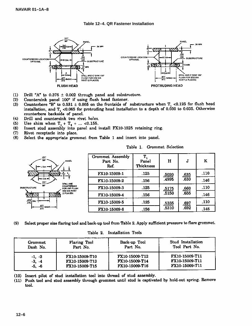
NAVAIR 01–1A–8
12–6
Table 12–4. QR Fastener Installation

NAVAIR 01–1A–8
12–7
Table 12–5. Live Lock Structural Panel Fasteners
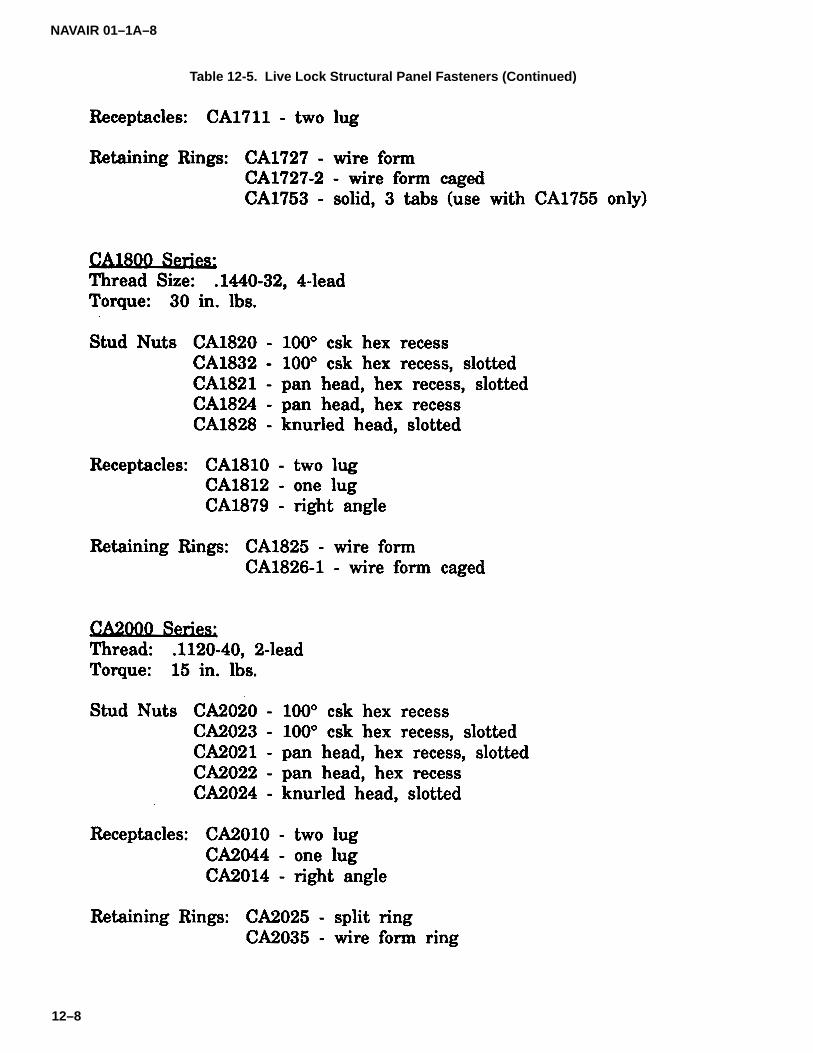
NAVAIR 01–1A–8
12–8
Table 12-5. Live Lock Structural Panel Fasteners (Continued)

NAVAIR 01–1A–8
12–9
Table 12–6. Live Lock CA2000 Series Fastener Installation
Table 12–7. Live Lock CA1800 Series Fastener Installation

NAVAIR 01–1A–8
12–10
Table 12–8. Live Lock CA1700 Series Fastener Installation

NAVAIR 01–1A–8
12–11
Table 12–9. Mark IV Structural Panel Fasteners

NAVAIR 01–1A–8
12–12
Table 12–10. Mark IV Fastener Installation
Table 12–11. Paneloc Quarter-turn Fasteners

NAVAIR 01–1A–8
12–13
Table 12–12. Paneloc Quarter-turn Fastener Installation
(1) Drill “A” through panel.(2) Countersink panel 100� to “B” if installing flush head stud.(3) Drill “C” through substructure.(4) Locate, drill, and countersink two rivet holes for receptacle per dimensions given above.(5) Insert stud into panel.(6) Drop retaining ring over stud and push ring down until it snaps into retaining groove.(7) Rivet receptacle into place.
Table 12–13. Paneloc Quarter–turn Fastener Torques and Clamping Forces

NAVAIR 01–1A–8
12–14
Table 12–14. Milson Panel Fastener Selection

NAVAIR 01–1A–8
12–15
Table 12-14. Milson Panel Fastener Selection (Continued)

NAVAIR 01–1A–8
12–16
Table 12–15. Milson Panel Fastener Hole Preparation
Figure 12–3. Camloc 4002 Series Fastener

NAVAIR 01–1A–8
12–17/(12–18 blank)Change 1
(PF 3– 1/2–38)
(PS 3–1/2)
(PC 3–1/2)
Figure 12–4. Dzus Panel - Line Fastener(Typical Installation for Dzus PF 3–1/2–38 Stud,
PC 3–1/2 Cup, and PS 3–1/2 Spring)
12–5. REMOVAL OF THREADED PANEL FASTEN-ERS. Use the following procedure for removal ofthreaded panel fasteners:
a. Remove receptacle by drilling out the rivets.
b. Remove stud by pulling off the retaining ringand withdrawing the stud from the panel.
12–6. PRECAUTIONS WHEN USING QUICK-RE-LEASE FASTENERS. Observe the followingprecautions when using quick-release and structuralpanel fasteners:
a. Use proper driver bit in accordance with thetype of recess (refer to Section V). Screwdrivers, ratch-ets, and speed wrenches may be used for fastenerinstallation and removal.
b. Use fasteners of proper grip length to preventdamaging the structure or fastener.
c. Ensure the proper counterbore size is providedfor retaining rings or that spacers are used. A formed-in-place gasket shall not be substituted for a spacer.
d. Place panel in position and align studs withholes. Do not use studs as handles. Engage studs byhand before applying torque.
e. Start all fasteners in the pattern before applyingtorque to any fastener. Torque fasteners in a smooth,uniform manner; do not snap load or overtorque.
f. Inspect for gaps or misalignment. If present,disassemble the unit, check stud and receptacle forproper operation, check alignment, ensure no foreignmaterial is present in the joint area, and reassemble.


NAVAIR 01–1A–8
13–1
SECTION XIII
CABLES
13–1. CABLES.
13–2. This section provides information on types of air-craft cables and cable hardware.
13–3. TYPES OF CABLES.
13–4. The following types of cables are used in aircraftapplications:
a. Flexible Cables. MIL-W-83420 flexible, pre-formed, carbon steel and CRES (corrosion-resistantsteel) cables and MIL-W-18375 flexible, preformed,non-magnetic CRES cables are available in 7X7 and7X19 configurations (see Figure 13-1). 7X7 cables con-sist of six strands of seven wires laid around a corestrand of seven wires. 7X19 cables consist of sixstrands of nineteen wires laid around a core strand ofnineteen wires. Physical properties for flexible cablesare provided in Table 13-1. Interchangeability require-ments of flexible cables are as follows:
1. MIL-W-83420, Composition B CRES cablemay be substituted for MIL-W-83420, Composition Acarbon steel cable in 1/16, 3/32, 1/2, 9/16, 5/8, and3/4-inch diameters only. Other sizes shall not be substi-tuted due to strength requirements.
2. MIL-W-83420, Composition A carbon steelcable shall not be substituted for MIL-W-83420, Com-position B or MIL-W-18375 CRES cable.
NOTENote cable substitutions on inspectionschedule and inspect twice as often asnormal.
b. Nylon-Jacketed Cables. Most cable wear oc-curs at pulleys due to friction between the wires. Wearis compounded by dirt working its way in and lubricationworking its way out of uncoated cables. Vibration hard-ens wires resulting in fracturing and eventual cableseparation. Nylon-jacketed cables are manufactured byextruding a flexible, nylon coating over a MIL-W-83420CRES cable. The nylon coating extends the service lifeof the cable, increases lubrication protection, and re-duces dirt penetration and the effect of vibration.
c. Non-Flexible Cables. MIL-W-87161 nonflex-ible preformed carbon steel and CRES cables areavailable in 1X7 and 1X19 configurations (see Figure13-2). 1X7 cable consists of six wires laid around a corewire. 1X19 cable consists of six wires laid clockwisearound a core wire and twelve wires laid counterclock-wise around the inner strand. Physical properties fornon-flexible cables are provided in Table 13-2.
Figure 13–1. Flexible Cable Cross Section

NAVAIR 01–1A–8
13–2
Table 13–1. Flexible Cable Construction and Physical Properties
d. Rescue Hoist Cables. MIL-W-83140, Type Inon-rotating, preformed stainless steel cables are avail-able in 19X7 configuration. They are used in aircraftrescue hoist applications. Physical properties for res-cue hoist cables are provided in Table 13-3.
e. Lockclad Cable. Lockclad cable limits differen-tial expansion/contraction between cable and airframeand increases cable rigidity to reduce cable stretch un-der load. Lockclad cable consists of steel cable with a6061 aluminum tube swaged over the surface. Thestrength of the cable is in the steel cable itself, and aslong as the cable is not damaged, the assembly is ser-viceable. Replace or repair lockclad cable when one ofthe conditions shown in Figure 13-3 exists. Refer toNAVAIR 01-1A-1 Structural Repair Manual for repairprocedures.
13–5. AIRCRAFT CABLE TEMPERATURE LIMI–TATIONS.
13–6. When temperatures below that at which a cableis rigged are encountered, the aircraft structure con-tracts and cables slacken up. When temperatureshigher than that at which a cable is rigged are encoun-tered, the aircraft structure expands and cable tensionincreases. Use of MIL-W-18375 cable where required
by design and service specifications reduces this prob-lem. The coefficient of expansion is approximately 30%higher than that of MIL-W-83420, and similar to that ofthe aircraft structure. Thus, changes in tension due totemperature variations are reduced.
NOTE
In control systems where temperatureregulators are installed, the rigging ten-sions shall be as called out in the AircraftMaintenance Handbook regardless oftemperatures encountered.
13–7. CABLE DAMAGE AND INSPECTION.
13–8. Since most aircraft control cables are oversizeand have up to 50% excess strength of design loads,cable failure is rarely abrupt, but is progressive over pe-riods of extended use. Several wires may break soonafter putting the cable into service due to being underhigh tension or being harder than other wires. However,few additional wires will break in normal service forsome time. Reduction in cable strength due to brokenwires depends upon the concentration rather than thetotal number per cable.

NAVAIR 01–1A–8
13–3
Figure 13–2. Nonflexible Cable Cross Section
Table 13–2. Nonflexible Cable Construction and Physical Properties

NAVAIR 01–1A–8
13–4
Table 13–3. Construction and Physical Properties (MIL-W-83140)
a. Broken Wires in Critical Fatigue Areas. CriticalFatigue Areas are the areas of a cable that contact apulley or sheave, pass through a fairlead, an area ofcable that is flexed, rubbed or worked, or an area withinone foot of a swaged–on fitting (swaging may pinch thewires resulting in premature failure). Inspect Critical Fa-tigue Areas by passing a cloth over the cable to snagbroken wires. Since broken wires do not always pro-trude, inspection with a magnifying glass may benecessary. Cables having one or more broken wires ina Critical Fatigue Area shall be replaced immediately.
NOTE
Replace cables having a single brokenwire in a Critical Fatigue Area, since thepotential exists for unraveling which couldresult in restriction of movement throughpulleys or fairleads.
b. Broken Wires in Uncritical Areas. UncriticalAreas are areas where the cable is not worked in anyway other than a straight pulling motion. Cables in a noncritical area may have up to three broken wires (7x7cable) per inch and up to six broken wires (7x19 cable)per inch before replacement is required. Note brokenwires in an Uncritical Area in an inspection report andcheck frequently for further damage.
c. Broken Wires in Rescue Hoist Cables. Replacerescue hoist cables having one or more broken wires.
d. Corrosion and Wear. Inspect cables for corro-sion or wear by moving controls to extreme positions toreveal the cable in the pulley, drum, or fairlead area. Ifcorrosion is present, visually inspect the interior of thecable without reverse twisting or causing damage to thecable. Corrosion on interior strands of the cable re-quires replacement. If corroded or badly worn, replacethe cable even if the number of broken wires is less thanthat specified for mandatory replacement. Remove ex-ternal corrosion with a fiber brush.
e. Kinked Cable. Kinks force strands and wiresout of position and cause excessive cable wear. Theyare caused by improper unreeling and/or handling of thecable. Even though the kink may be straightened, therelative lay between the strands has been disturbed andthe cable will not provide maximum performance. Re-place or repair the cable in accordance with NAVAIR01-1A-1.
f. Cracks in Nylon-jacketed Cables. Replace ny-lon-jacketed cables with cracks in the jacket.
g. Severed Cables. Repair or replace severed orseverely damaged cables immediately. Refer to theNAVAIR 01-1A-1 Structural Repair manual for repairprocedures.
h. Control Cable External Wear Patterns. Normalwear may occur on one side of the cable or around itsentire circumference. Replace cables when outer wirewear exceeds the limits of Figure 13-4.

NAVAIR 01–1A–8
13–5
Figure 13–3. Lockclad Cable Damage
13–9. CABLE HARDWARE.
13–10. The following are types of cable hardware andinstallation procedures.
a. Turnbuckles. Turnbuckles are used to adjusttension in cable systems. They have barrel-shapedsleeves with internal left- and right-hand threads at op-posite ends into which externally threaded cableterminals are threaded (refer to Table 13-4). Cables arefabricated to such a length that when installed, a suffi-cient number of threads on the terminal ends arethreaded into the barrel to sustain the load. Thread ter-minals into the barrel an equal amount on both ends. Donot thread the terminal more than four thread lengthsinto the turnbuckle on initial installations (see Figure13-5).
b. Miscellaneous Cable Hardware. Refer toTables 13-5 through 13-11 for information on fork, eye,and threaded end cable terminals, bushings, shackles,and thimbles.
c. Swaged Ball Terminals. Use MS20663 double-shank and MS20664 single-shank ball end cableterminals in limited clearance applications (refer toTables 13-12 and 13-13). Slip the hollow terminal overthe cable and swage in position using a hand swagingmachine. Single-shank terminals are used only at cableends. Double-shank terminals are used in the middle orat the end of cables.
d. Cable Stops. Cable stops consist of a taperedlocking screw and locking nut (see Figure 13-6) and areused on some aircraft trim tab system cables. To installa cable stop, clamp it onto the cable in the proper posi-tion, hold the screw with an open-end wrench, andthread the nut over the screw. Swage or solder the stopin place.
13–11. CABLE REPAIR.
13–12. Refer to NAVAIR 01-1A-1 Structural Repairmanual for cable repair procedures.

NAVAIR 01–1A–8
13–6
Figure 13–4. Control Cable Wear Limit

NAVAIR 01–1A–8
13–7
Table 13–4. Turnbuckle Assembly
Table 13-4. Turnbuckle Assembly (Continued)

NAVAIR 01–1A–8
13–8
Table 13-4. Turnbuckle Assembly (Continued)

NAVAIR 01–1A–8
13–9
Table 13-4. Turnbuckle Assembly (Continued)
Table 13-4. Turnbuckle Assembly (Continued)

NAVAIR 01–1A–8
13–10
Table 13-4. Turnbuckle Assembly (Continued)

NAVAIR 01–1A–8
13–11
Table 13-4. Turnbuckle Assembly (Continued)
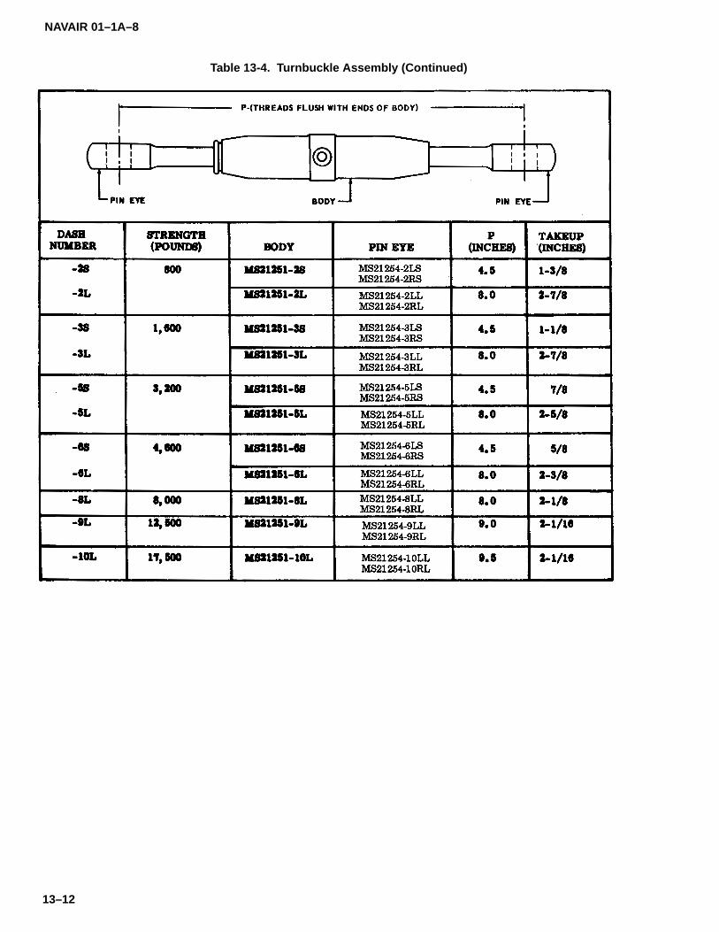
NAVAIR 01–1A–8
13–12
Table 13-4. Turnbuckle Assembly (Continued)

NAVAIR 01–1A–8
13–13
Figure 13–5. Turnbuckle Thread Tolerance
Table 13–5. MS20658 Fork End Cable Terminal
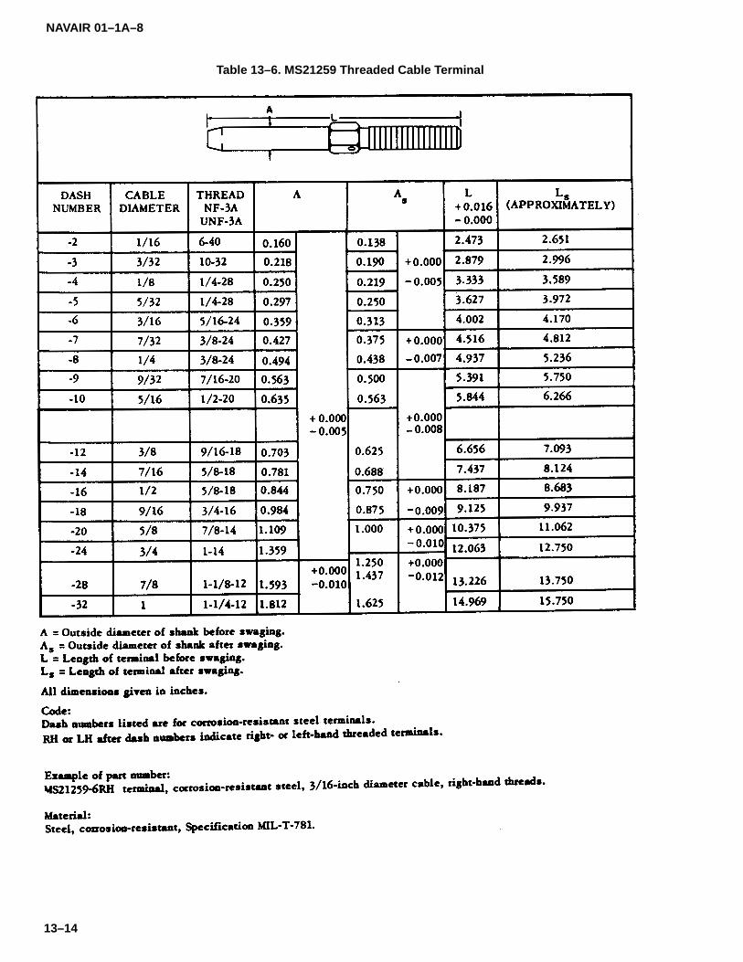
NAVAIR 01–1A–8
13–14
Table 13–6. MS21259 Threaded Cable Terminal

NAVAIR 01–1A–8
13–15
Table 13–7. MS20667 Fork End Cable Terminal

NAVAIR 01–1A–8
13–16
Table 13–8. MS20668 Eye End Cable Terminal
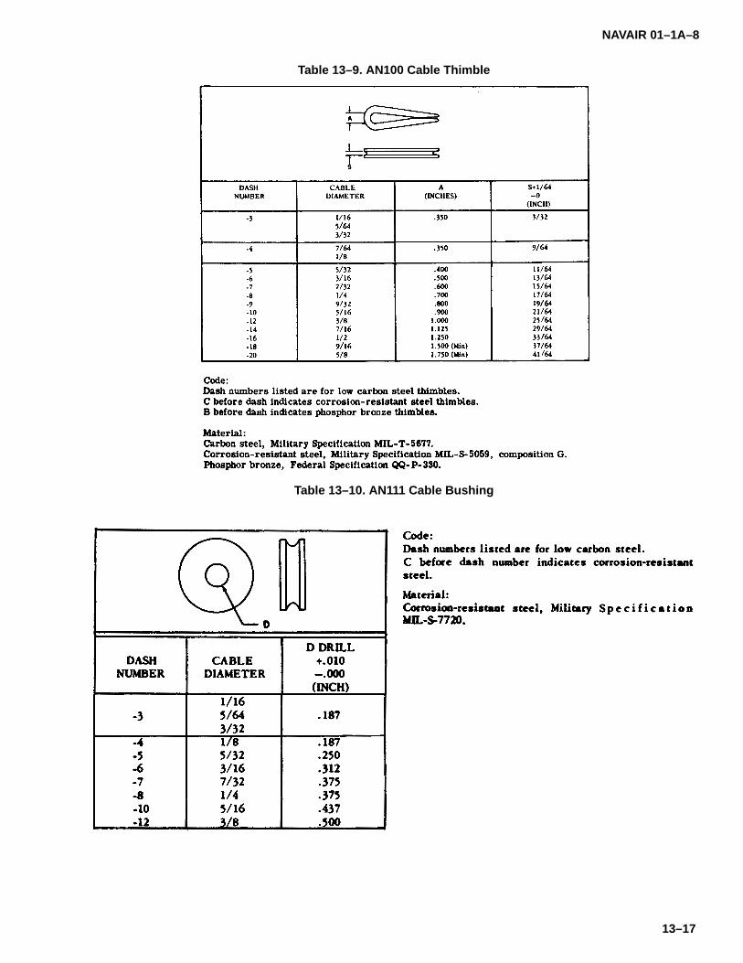
NAVAIR 01–1A–8
13–17
Table 13–9. AN100 Cable Thimble
Table 13–10. AN111 Cable Bushing
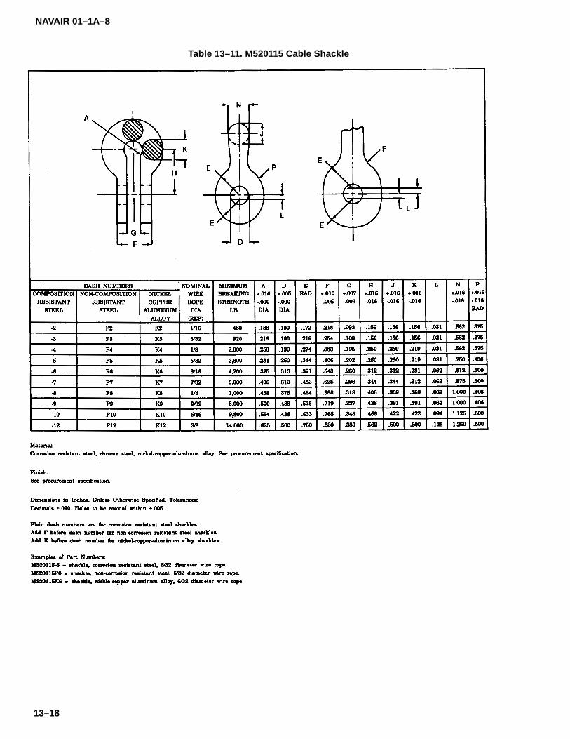
NAVAIR 01–1A–8
13–18
Table 13–11. M520115 Cable Shackle
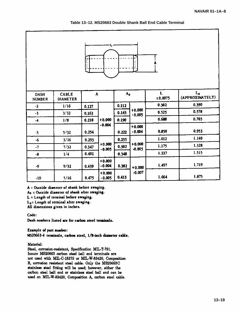
NAVAIR 01–1A–8
13–19
Table 13–12. MS20663 Double Shank Ball End Cable Terminal
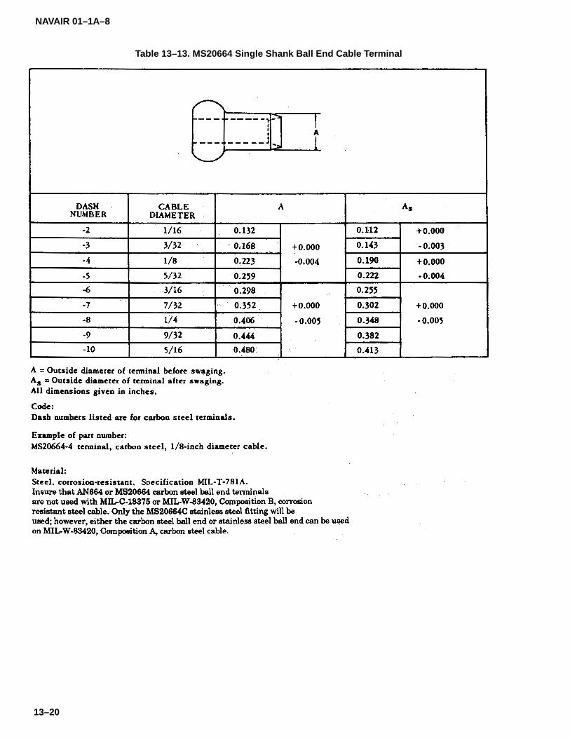
NAVAIR 01–1A–8
13–20
Table 13–13. MS20664 Single Shank Ball End Cable Terminal
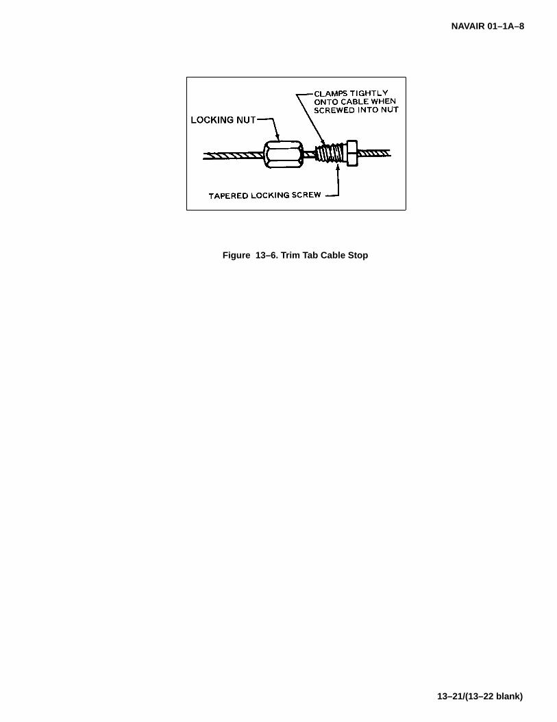
NAVAIR 01–1A–8
13–21/(13–22 blank)
Figure 13–6. Trim Tab Cable Stop


NAVAIR 01–1A–8
14–1
SECTION IXV
CONTROL RODS
14–1. CONTROL RODS.
14–2. Control rods are links in mechanical systemswhich allow adjustment of main flight controls, engineaccessories, etc. They are available in several stylesand sizes for use in aircraft applications. A typical con-trol rod assembly is shown in Figure 14-1. NAS354control rods, NAS357 control tubes, and NAS360 con-trol tubes are shown in Tables 14-1 through 14-3. Referto Tables 14-4 through 14-7 for several styles of controltube assemblies. These assemblies are manufacturedwith riveted or welded rod ends.
NOTE
Install an MS20002 or equivalent washerunder the retaining nut or bolt head whenusing ball bearing control rods to preventthe rod from slipping over the retainer.Tightly clamp the inner race of the bearingto the face of the washer and supportingstructure. Washers may also be used withclevis control rods, if necessary.
14–3. ROD END TERMINAL FITTINGS.
14–4. Rod end terminal fittings are available in the fol-lowing styles:
a. Threaded. AN490 threaded rod ends are madeof alloy steel and are manufactured with 1/4-28 to 3/8-24series threads (refer to Table 14-8).
b. Clevis. Clevis rod ends are available with bothwide and narrow forks. MS27976 plain clevis rod endsare not adjustable after installation (refer to Table 14-9).MS27975 adjustable clevis rod ends are designed withinternal threads which allow length adjustment afterinstallation (refer to Table 14-10).
c. Bearing. Bearing rod ends are available withexternal threads (MS21242) or with internal threads(MS21243). Refer to Tables 14-11 and 14-12 for in-formation on bearing rod ends.
NOTE
Inspect internally threaded rod endsthrough the inspection hole to ensureproper thread engagement (i.e. when thethreads of the rod end are visible in the in-spection hole). If visual inspection isdifficult, insert a piece of wire into the holeto check thread engagement.
14–5. CONTROL TUBE REPAIR.
14–6. It is recommended that all damaged controltubes be replaced and the terminals salvaged. Tubesdamaged in the center 1/3 of the assembly require man-datory replacement. Repaired control tubes shall beperfectly straight to provide maximum strength. Sleevereinforcements may be added to steel tubes with ascarfed or fishmouth cut and then welded in place.

NAVAIR 01–1A–8
14–2
Table 14–1. NAS354 Control Rod
Table 14–2. NAS357 Control Tubes

NAVAIR 01–1A–8
14–3
Table 14–3. NAS360 Control Rod
Table 14–4. NAS355 Control Tube Assembly (Riveted Threaded Rod Ends)

NAVAIR 01–1A–8
14–4
Table 14–5. NAS356 Control Tube Assembly (Riveted Clevis & Threaded Rod Ends)
Table 14–6. NAS358 Control Tube Assembly (Welded Threaded Rod Ends)
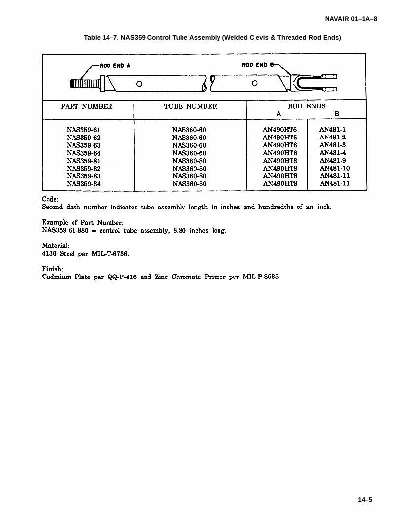
NAVAIR 01–1A–8
14–5
Table 14–7. NAS359 Control Tube Assembly (Welded Clevis & Threaded Rod Ends)
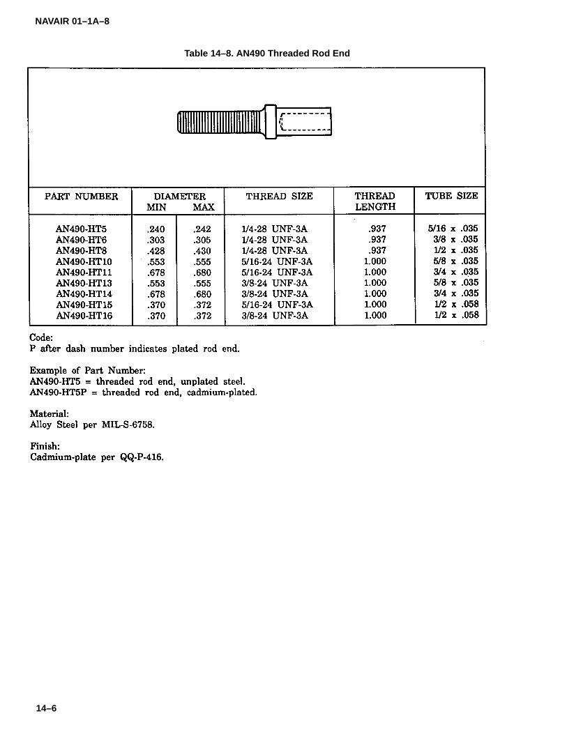
NAVAIR 01–1A–8
14–6
Table 14–8. AN490 Threaded Rod End
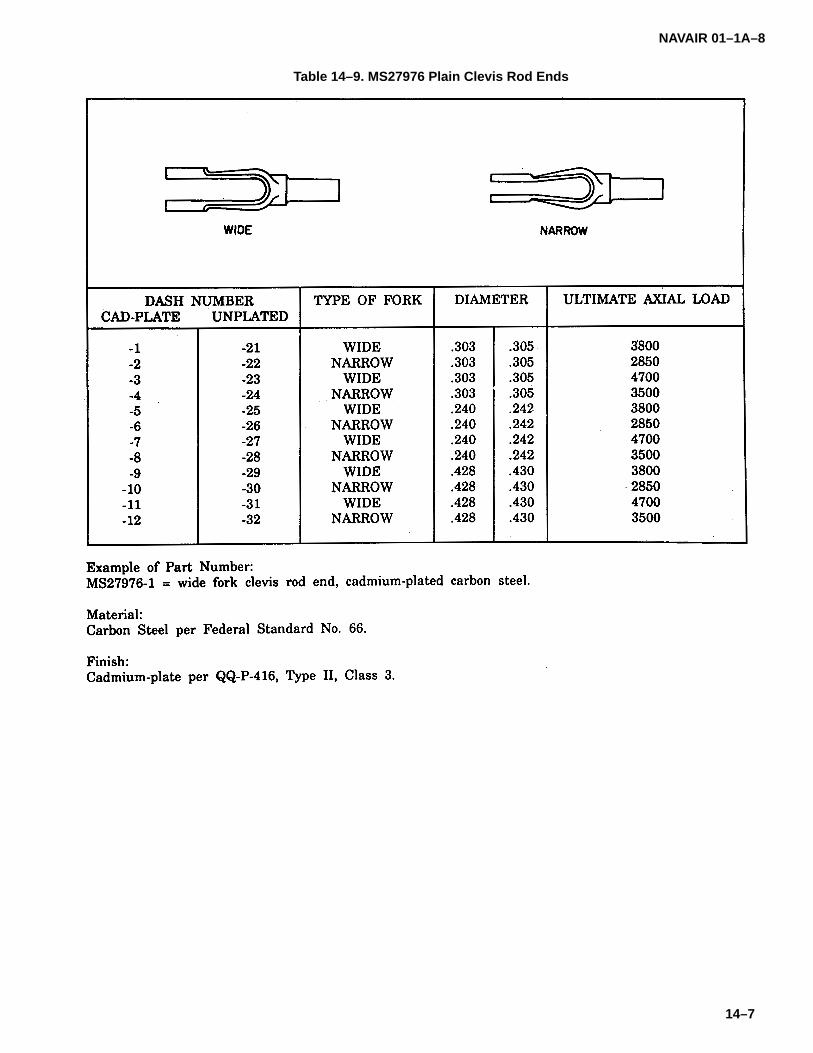
NAVAIR 01–1A–8
14–7
Table 14–9. MS27976 Plain Clevis Rod Ends
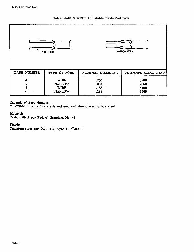
NAVAIR 01–1A–8
14–8
Table 14–10. MS27975 Adjustable Clevls Rod Ends

NAVAIR 01–1A–8
14–9
Table 14–11. MS21 242 Plain Bearing Rod End, Externally Threaded

NAVAIR 01–1A–8
14–10
Table 14–12. MS21243 Plain Bearing Rod End, Internally Threaded

NAVAIR 01–1A–8
15–1
SECTION XV
CLAMPS
15–1. CLAMPS.
15–2. Hose and loop clamps are used in aircraft ap-plications. Hose clamps utilize an adjustable latchassembly by which the tightness of the clamp may beadjusted. Loop clamps are designed in center-mount-ing and elongated styles. They may be cushioned forprotection of the part being clamped. Loop clamps donot utilize a latch, but rather are secured by a screw as-sembly.
15–3. HOSE CLAMPS. The following styles of hoseclamps are available for use in aircraft applications:
a. MS21920 Flat Band Hose Clamps. Flat bandhose clamps are manufactured from CRES and alloysteel in sizes ranging from 2-1/2-inch to 10-inch insidediameter (refer to Table 15-1). Release mechanisms in-clude standard latches, T-bolts, or any other mechanismwithin the requirements of the specification.
b. NAS1922 Tangential Worm Hose Clamps. Tan-gential worm hose clamps are manufactured from 18-8austenitic stainless steel in sizes ranging from 1/2-inchto 10-inch inside diameter (refer to Table 15-2). Releasemechanisms include standard or quick-disconnectlatches with slotted or hex head screws. The screwhead may be drilled for lock-wiring.
15–4. LOOP CLAMPS. The following styles of loopclamps are available for use in aircraft applications:
CAUTION
Before making substitutions, refer to theapplicable TMS so as not to use a lowtemperature clamp in a high temperatureapplication.
a. Center-Mounting Loop Clamps. Center-mounting loop clamps are circular clamps designed tosecure a single hose, tube, cable, etc. They are avail-able in several materials, size ranges, and temperaturelimitations. Several are described as follows:
1. MS21322 and MS21333 Loop Clamps.These plain and cushioned loop clamps are manufac-
tured from aluminum alloy or carbon steel. They areavailable in sizes ranging from 1/8-inch to 4-inch nomi-nal diameter (refer to Table 15-3).
2. MS9349 Through MS9352 Joggled LoopClamps. These plain and cushioned loop clamps aredesigned with a joggle to provide a flush surface wherethe clamp is fastened. They are manufactured fromCRES or aluminum in sizes ranging from 1/8-inch to2-inch nominal diameter (refer to Table 15-4).
3. MS21919 Support Loop Clamp. Thesecushioned loop clamps are manufactured from CRES,aluminum, and carbon steel in sizes ranging from1/16-inch to 4-1/8-inch nominal diameter (refer to Table15-5). The cushions are made of ethylene propylene,nitrile, chloroprene, silicone, or fluorosilicone.
4. MS21106 1200�F Loop Clamp. Both theband and cushion of these high temperature loopclamps are made of CRES. They are available in sizesranging from 1/8-inch to 4-1/8-inch nominal diameter(refer to Table 15-6).
5. MS21122 Polytetrafluoroethylene (PTFE)Loop Clamps. These clamps consist of a CRES or alu-minum alloy band with a polytetrafluoroethylenecushion. They are available in sizes ranging from1/8-inch to 4-1/8-inch nominal diameter (refer to Table15-7).
b. Elongated Loop Clamps. Elongated loopclamps, designed to secure two or more tubes, hoses,cables, etc., are available in CRES or carbon steel inseveral sizes. Multiple tube and double tube loopclamps are described as follows:
1. MS9391 Multiple Tube Loop Clamp. Multi-ple tube loop clamps may secure 2 or 3 tubes rangingfrom 1/8-inch to 3/8-inch nominal diameter (refer toTable 15-8). MS9391 loop clamps are manufacturedfrom CRES.
2. MS21334 Double Tube Loop Clamp.Double tube loop clamps are used to secure 2 tubes of1/8-inch to 2-inch nominal diameter (refer to Table 15-9).They are manufactured from carbon steel, and are avail-able in plain and cushioned styles.

NAVAIR 01–1A–8
15–2
Table 15–1. MS21920 Flat Band Hose Clamp
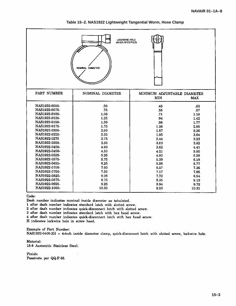
NAVAIR 01–1A–8
15–3
Table 15–2. NAS1922 Lightweight Tangential Worm, Hose Clamp

NAVAIR 01–1A–8
15–4
Table 15–3. MS21322 and MS21333 Plain or Cushioned Loop Clamps
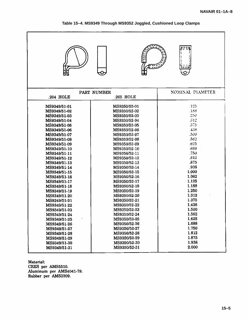
NAVAIR 01–1A–8
15–5
Table 15–4. MS9349 Through MS9352 Joggled, Cushioned Loop Clamps

NAVAIR 01–1A–8
15–6
Table 15–5. MS21919 Cushioned, Support Loop Clamp

NAVAIR 01–1A–8
15–7
Table 15–5. MS21919 Cushioned, Support Loop Clamp (Continued)
Code:DE before dash number indicates aluminum band with ethylene propylene cushion.DF before dash number indicates aluminum band with nitrile cushion.DG before dash number indicates aluminum band with chloroprene cushion.CE before dash number indicates CRES band with ethylene propylene cushion.CF before dash number indicates CRES band with nitrile cushion.CH before dash number indicates CRES band with silicone cushion.CG before dash number indicates CRES band with chloroprene cushion.CJ before dash number indicates CRES band with fluorosilicone cushion.F before dash number indicates carbon steel band with nitrile cushion.G before dash number indicates carbon steel band with chloroprene cushion.H before dash number indicates carbon steel band with silicone cushion.
Example of Part Number:MS21919CJ50 = 3–1/8–inch tube OD CRES clamp, fluorosilicone cushion.
Material:Band: Aluminum Alloy. CRES. Low Carbon Steel.
Cushion: Ethylene Propylene. (–70 to 275�F)Nitrile. (–60 to 212�F)Chloroprene. (–60 to 212�F)Silicone. (–178 to 400�F)Fluorosilicone. (–90 to 450�F)
Finish:Chemical conversion coat aluminum alloy.Passive CRES.Cadmium–plate carbon steel.
Note: Clamps with low carbon steel bands are inactive for new aircraft design as of 01 October 1982.

NAVAIR 01–1A–8
15–8
Table 15–6. MS21106 1200�F, Cushioned Loop Clamp
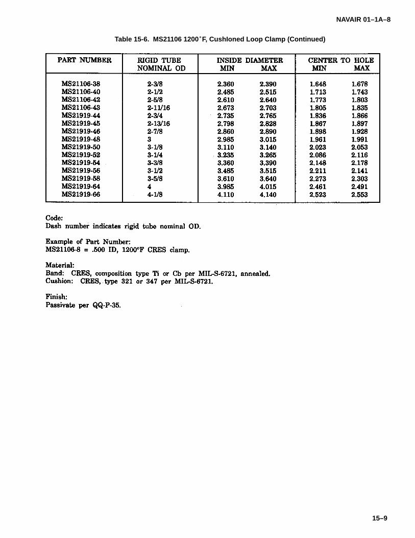
NAVAIR 01–1A–8
15–9
Table 15-6. MS21106 1200�F, CushIoned Loop Clamp (Continued)

NAVAIR 01–1A–8
15–10
Table 15–7. MS21122 Polytetrafluoroethylene Loop Clamp
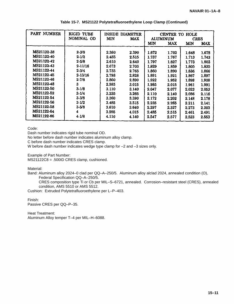
NAVAIR 01–1A–8
15–11
Table 15-7. MS21122 Polytetrafluoroethylene Loop Clamp (Continued)
Code:Dash number indicates rigid tube nominal OD.No letter before dash number indicates aluminum alloy clamp.C before dash number indicates CRES clamp.W before dash number indicates wedge type clamp for –2 and –3 sizes only.
Example of Part Number:MS21122C8 = .500ID CRES clamp, cushioned.
Material:Band: Aluminum alloy 2024–0 clad per QQ–A–250/5. Aluminum alloy alclad 2024, annealed condition (O),
Federal Specification QQ–A–250/5.CRES composition type Ti or Cb per MIL–S–6721, annealed. Corrosion–resistant steel (CRES), annealedcondition, AMS 5510 or AMS 5512.
Cushion: Extruded Polytetrafluoroethylene per L–P–403.
Finish:Passive CRES per QQ–P–35.
Heat Treatment:Aluminum Alloy temper T–4 per MIL–H–6088.

NAVAIR 01–1A–8
15–12
Table 15–8. MS9391 Multiple Tube, Detachable Cushion Loop Clamp

NAVAIR 01–1A–8
15–13/(15–14 blank)
Table 15–9. MS21334 Double Tube Plain or Cushioned Loop Clamp


NAVAIR 01–1A–8
16–1
SECTION XVI
INSPECTION AND INSTALLATION OF V–BAND COUPLINGS
16–1. V-BAND COUPLINGS.
16–2. The instruction given is a brief outline of precau-tionary procedures and installation techniques toimprove the reliability of V-couplings used in aircraft andmissiles.
NOTE
The instructions are general and are ap-plicable except when otherwise specifiedin the manuals for the specific aerospacevehicle. If there is a conflict between thismanual and the manuals for a particularaerospace vehicle, subsequent technicalorders, technical notes, or change orders,the latter will govern in all cases.
16–3. PRE-INSTALLATION CHECKS.
16–4. Exercise particular care during handling andinstallation of ducts and tubes to ensure that flangefaces are not scratched, distorted or deformed.
a. Clean flange faces free of dirt, grease and cor-rosion.
b. Use protective flange caps on the ends of allducts until the installation progresses to the point whereremoval of the cap is essential to continuing with theinstallation.
c. Use care during the installation of ducts andtubes to ensure mating and alignment of flanges. Apoorly-fitted joint requires excessive torque on the T-boltto close the joint and imposes structural loads on the V-Band Clamp. Adjacent support clamps or bracketsshould remain loose until installation of the coupling hasbeen completed. When connections are by V-BandCouplings, the weight of the components should be fullysupported during the fit-up and installation of the cou-pling. Refer to the applicable maintenance, overhaul orservice instructions for joint and clearances.
d. Clean the flange faces and inspect every timea clamp is removed. Clean the flange faces by wipingwith a clean cloth. Do not use a wire brush to remove dirt.
16–5. INSTALLATION.
16–6. Check the part number to ensure that the propercoupling is being installed.
a. When re-installing a used coupling, check it fortwist or distortion. Visually check the V-section forspreading at the open ends or other signs of distortion.Check spot weld or rivets for condition and security. Thecorner radii should be carefully checked for tool marksand cracks. Couplings in poor condition should be re-placed.
b. Check the threads on the T-bolt for wear andcondition. If there is any sign of wear, corrosion, gallingor deformation, install a new T-bolt or coupling.
c. Check the T-bolt for straightness; however, if itis bent it will be necessary to determine if the bend is in-tentional. Some small diameter couplings have curvedT-bolts. Check the applicable illustrated parts break-down for part identification. If in doubt, install a newT-bolt or coupling.
d. The trunnion and latch should be checked forfreedom of movement or other evidence of overloading.
e. Avoid twisting, spreading or bending of the cou-pling when positioning the coupling on the joint.
16–7. GASKETS.
16–8. When gaskets are used in the joint, exercise par-ticular care in handling to avoid nicks and burrs on thegasket surfaces. Whenever a joint is disassembled af-ter service operations, a new gasket should be usedwhen reassembling to ensure maximum sealing effi-ciency. Exercise care to ensure that the gasket isproperly seated.
16–9. TORQUE.
16–10. Before installing the coupling, determine the cor-rect torque for tightening the T-bolt nut by referring to theapplicable Maintenance, Overhaul, or Service Instruc-tions. Correct torque is vital in assuring reliability of thecoupling.
16–11. NUTS.
16–12. Several different types of nuts are used on the T-bolts. If a nut is lost or damaged, replace it with a cleanand undamaged identical type nut. Be careful to matchthe T-bolt threads.

NAVAIR 01–1A–8
16–2
16–13. To install the coupling on the joint, place the cou-pling over one of the tube ends far enough to clear theflange. Install the gasket and mate the flanges. Relo-cate the coupling over both flanges and press thecoupling closed. Engage the quick coupler latch orinstall the nut. Be sure the T-bolt is correctly seated.Tighten the nut to about two-thirds of the specifiedtorque and tap the coupling lightly around the circumfer-ence of the band with a plastic or other non-metallicmallet. On multibolt assemblies, nuts should be drawnup equally. Continue, alternately tightening and tappingwhere possible until the torque indicated on the torquewrench stabilizes at the specified value. Exercise cau-tion to avoid overtorquing.
16–14. Do not attempt to seal a leaking joint by overtigh-tening the T-bolt. Check for a wrong coupling, adamaged flange, or a defective gasket.
16–15. To prevent complete separation of the joint in theevent of T-bolt failure, safetywire the coupling. Lockwireshall be Federal Specification QQ-W-423 type and di-ameter shall be 0.028 to 0.051 inch.
NOTE
Lockwire will be installed through bandloops which retain the T-bolt and T-bolttrunnion or quick-disconnect coupler, seeFigure 16-1. A double loop of single strainwire is required. Install first loop firmly inplace; second loop should not be overstressed by twisting ends of wires.
Figure 16–1. V-Band Coupling Safety Wiring Techniques

NAVAIR 01-1A-8
Index-1
ALPHABETICAL INDEX
Subject Paragraph, Subject ParagraphFigure, Table Figure, Table
Number Number
B
Blind Fastener Identification 3-61. . . . . . . . . . . . . . . . . Blind Fastener Pattern Layout 3-63. . . . . . . . . . . . . . . . Blind Fastener Removal 3-93, T3-49. . . . . . . . . . . . . . .
Drilling Procedure 3-94d. . . . . . . . . . . . . . . . . . . . . . . . Drill Set-up 3-94a, F3-28. . . . . . . . . . . . . . . . . . . . . . . . Fastener Knockout 3-94e, F3-29. . . . . . . . . . . . . . . . . Vacuum Pad Indexing 3-94c, F3-27. . . . . . . . . . . . . . Vacuum System Set-up 3-94b, F-26. . . . . . . . . . . . . .
Blind Fastener Requirements 3-60. . . . . . . . . . . . . . . . Blind Fastening Systems 3-57. . . . . . . . . . . . . . . . . . . . Blind Rivet Inspection 3-91. . . . . . . . . . . . . . . . . . . . . . .
Cherrylock, Cherrymax, and Olympic Rivets 3-92c. Cherry Rivets 3-92a. . . . . . . . . . . . . . . . . . . . . . . . . . . . Trimmed Stems 3-92b. . . . . . . . . . . . . . . . . . . . . . . . . .
Blind Rivets, Types of 3-59. . . . . . . . . . . . . . . . . . . . . . . Self-Plugging, Bulbed 3-59c. . . . . . . . . . . . . . . . . . . . . Self-Plugging, Friction Locked 3-59d. . . . . . . . . . . . . Self-Plugging, Mechanically Locked 3-59b. . . . . . . . Self-Plugging, Standard 3-59a. . . . . . . . . . . . . . . . . . .
Bolt Hardness 5-5. . . . . . . . . . . . . . . . . . . . . . . . . . . . . . . Bolt Hole Preparation 5-6. . . . . . . . . . . . . . . . . . . . . . . .
Light-Drive Fit 5-7. . . . . . . . . . . . . . . . . . . . . . . . . . . . . Bolt Identification 5-4. . . . . . . . . . . . . . . . . . . . . . . . . . . . Bolts 5-1. . . . . . . . . . . . . . . . . . . . . . . . . . . . . . . . . . . . . . .
Grip Length 5-3. . . . . . . . . . . . . . . . . . . . . . . . . . . . . . . Bolts, Aircraft Machine 5-9. . . . . . . . . . . . . . . . . . . . . . .
Engine Machine Bolts 5-10c. . . . . . . . . . . . . . . . . . . . Non-Magnetic CRES Machine 5-10b. . . . . . . . . . . . . Standard Aircraft Machine Bolts 5-10a. . . . . . . . . . . .
Bolts, Clevis 5-16. . . . . . . . . . . . . . . . . . . . . . . . . . . . . . . Bolts, Close-Tolerance Machine 5-11. . . . . . . . . . . . . .
Close-Tolerance Hex Head Machine Bolts 5-11a. . . Close-Tolerance High Strength Machine
Bolts 5-11c. . . . . . . . . . . . . . . . . . . . . . . . . . . . . . . . . . Close-Tolerance Titanium Machine Bolts 5-11b. . . .
Bolts, Close-Tolerance Shear 5-14. . . . . . . . . . . . . . . . Bolts, Full Threaded 5-15. . . . . . . . . . . . . . . . . . . . . . . . Bolts, Internal Wrenching 5-12. . . . . . . . . . . . . . . . . . . .
Drilled Socket Head Bolts 5-12b. . . . . . . . . . . . . . . . . Socket Head Bolts 5-12a. . . . . . . . . . . . . . . . . . . . . . .
Bolts, Self-Locking 5-20. . . . . . . . . . . . . . . . . . . . . . . . . . Bolts, 12-Point External Wrenching 5-13. . . . . . . . . . .
12-Point High Strength Bolts 5-13a. . . . . . . . . . . . . . 12-Point Machine Bolts 5-13b. . . . . . . . . . . . . . . . . . .
Bucking 2-49. . . . . . . . . . . . . . . . . . . . . . . . . . . . . . . . . . . Bucking and Shaving Rivets 2-48. . . . . . . . . . . . . . . . . Bucking Bars 2-50, F2-30. . . . . . . . . . . . . . . . . . . . . . . . Bucking Rivets 2-51. . . . . . . . . . . . . . . . . . . . . . . . . . . . .
Backing Up Rivets 2-51a. . . . . . . . . . . . . . . . . . . . . . . Filling Countersinks 2-51b. . . . . . . . . . . . . . . . . . . . . .
Bushing, Beaming 10-5. . . . . . . . . . . . . . . . . . . . . . . . . . Bushing, Removing 10-6. . . . . . . . . . . . . . . . . . . . . . . . . Bushings 10-1. . . . . . . . . . . . . . . . . . . . . . . . . . . . . . . . . . Bushings, Pressing In 10-4. . . . . . . . . . . . . . . . . . . . . . .
Arbor Press Method 10-4a, F10-2. . . . . . . . . . . . . . . . Drawn-In Method 10-4b. . . . . . . . . . . . . . . . . . . . . . . . Mallet Method 10-4d, F10-4. . . . . . . . . . . . . . . . . . . . . Vise Method 10-4c, F10-3. . . . . . . . . . . . . . . . . . . . . . .
Bushings, Beaming Holes for 10-3, F10-1. . . . . . . . . .
C
Cable Damage and Inspection 13-7. . . . . . . . . . . . . . . Broken Wires in Critical Fatigue Areas 13-8a. . . . . . Broken Wires in Rescue Hoist Cables 13-8c. . . . . . Broken Wires in Uncritical Areas 13-8b. . . . . . . . . . . Control Cable External Wear Patterns 13-8h. . . . . . Corrosion and Wear 13-8d. . . . . . . . . . . . . . . . . . . . . . Cracks in Nylon-Jacketed Cables 13-8f. . . . . . . . . . . Kinked Cable 13-8e. . . . . . . . . . . . . . . . . . . . . . . . . . . . Severed Cables 13-8g. . . . . . . . . . . . . . . . . . . . . . . . .
Cable Hardware 13-9. . . . . . . . . . . . . . . . . . . . . . . . . . . . Cable Stops 13-10d. . . . . . . . . . . . . . . . . . . . . . . . . . . . Miscellaneous Cable Hardware 13-10b. . . . . . . . . . . Swaged Ball Terminals 13-10c. . . . . . . . . . . . . . . . . . . Turnbuckles 13-10a, T13-4. . . . . . . . . . . . . . . . . . . . . .
Cable Repairs 13-11. . . . . . . . . . . . . . . . . . . . . . . . . . . . Cables 13-1. . . . . . . . . . . . . . . . . . . . . . . . . . . . . . . . . . . . Cables, Types of 13-3. . . . . . . . . . . . . . . . . . . . . . . . . . .
Flexible Cables 13-4a. . . . . . . . . . . . . . . . . . . . . . . . . . Lockclad Cable 13-4e. . . . . . . . . . . . . . . . . . . . . . . . . . Non-Flexible Cables 13-4c. . . . . . . . . . . . . . . . . . . . . . Nylon-Jacketed Cables 13-4b. . . . . . . . . . . . . . . . . . . Rescue Hoist Cables 13-4d. . . . . . . . . . . . . . . . . . . . .
Cable Temperature Limitations, Aircraft 13-5. . . . . . . . Cherry and Olympic Rivets, Interchange-
ability of 3-95. . . . . . . . . . . . . . . . . . . . . . . . . . . . . . . . . Cherrylock Blind Rivets 3-79. . . . . . . . . . . . . . . . . . . . . Cherrylock Rivets, Installation of 3-82. . . . . . . . . . . . . . Cherrylock Tooling 3-81, T3-44. . . . . . . . . . . . . . . . . . . .
Cherrylock Adapters and Extensions 3-81d. . . . . . . Cherrylock Hand Tooling 3-81a. . . . . . . . . . . . . . . . . . Cherrylock Hydroshift Tooling 3-81b. . . . . . . . . . . . . . Cherrylock Mechanical Tooling 3-81c. . . . . . . . . . . . .
Cherrymax Blind Rivets 3-83. . . . . . . . . . . . . . . . . . . . . Cherrymax Rivets, Installation of 3-86. . . . . . . . . . . . . Cherrymax Tooling 3-85, T3-46. . . . . . . . . . . . . . . . . . .
Cherrymax Adapters and Extensions 3-85c. . . . . . . Cherrymax Hand Tooling 3-85a. . . . . . . . . . . . . . . . . . Cherrymax Power Tooling 3-85b. . . . . . . . . . . . . . . . .
Clamps 15-1. . . . . . . . . . . . . . . . . . . . . . . . . . . . . . . . . . .

NAVAIR 01-1A-8
Index-2
ALPHABETICAL INDEX (Continued)
Subject Paragraph, Subject ParagraphFigure, Table Figure, Table
Number Number
Clamps, Hose 15-3. . . . . . . . . . . . . . . . . . . . . . . . . . . . . . MS21920 Fiat Band Hose Clamps 15-3a. . . . . . . . . . NAS1922 Tangential Worm Hose Clamps 15-3b. . .
Clamps, Loop 15-4. . . . . . . . . . . . . . . . . . . . . . . . . . . . . . Center-Mounting Loop Clamps 15-4a. . . . . . . . . . . . . Elongated Loop Clamps 15-4b. . . . . . . . . . . . . . . . . .
Collar Inspection 3-36. . . . . . . . . . . . . . . . . . . . . . . . . . . Composi-Lok Fasteners 3-118. . . . . . . . . . . . . . . . . . . . Composi-Lok II Fasteners 3-120. . . . . . . . . . . . . . . . . . Composi-Lok II Fasteners, Inspection of 3-125. . . . . . Composi-Lok II Fasteners, Installation of 3-124. . . . . Composi-Lok II Fasteners; Removal of 3-126. . . . . . . Composi-Lok ll Hole Preparation 3-122. . . . . . . . . . . . Composi-Lok II Installation Tooling 3-123. . . . . . . . . . . Control Rods 14-1. . . . . . . . . . . . . . . . . . . . . . . . . . . . . . Control Tube Repair 14-5. . . . . . . . . . . . . . . . . . . . . . . . Cotter Pins 2-47. . . . . . . . . . . . . . . . . . . . . . . . . . . . . . . . Countersinking and Dimpling 2-20. . . . . . . . . . . . . . . . . Countersinking Composite Structures 2-25. . . . . . . . . Countersinking, Machine 2-22. . . . . . . . . . . . . . . . . . . . Countersinking Metallic Structures 2-21. . . . . . . . . . . .
D
Dimpling Metallic Structures 2-23. . . . . . . . . . . . . . . . . Drilling 2-13. . . . . . . . . . . . . . . . . . . . . . . . . . . . . . . . . . . . Drilling Boron/Epoxy Laminates 2-19. . . . . . . . . . . . . . Drilling Equipment for Metallic Structures 2-14. . . . . .
Tool Maintenance 2-17. . . . . . . . . . . . . . . . . . . . . . . . . Drilling Graphite/Epoxy Laminates 2-16. . . . . . . . . . . .
Backup and Clamping 2-16a. . . . . . . . . . . . . . . . . . . . Coolants 2-16d. . . . . . . . . . . . . . . . . . . . . . . . . . . . . . . . Drill Selection 2-16b. . . . . . . . . . . . . . . . . . . . . . . . . . . Equipment Selection 2-16c. . . . . . . . . . . . . . . . . . . . .
Drilling Graphite/Epoxy Laminates, Hand 2-18. . . . . . Drilling Metallic Structures 2-15. . . . . . . . . . . . . . . . . . .
E
Eyebolts 5-17. . . . . . . . . . . . . . . . . . . . . . . . . . . . . . . . . .
F
Fasteners, Hole Preparation for Tapered-Shank 5-30Fasteners, Inspection of Tapered-Shank 5-32. . . . . . . Fasteners, Installation of Internal Wrenching 5-24. . . Fasteners, Installation of Tapered-Shank 5-31. . . . . . Fasteners, Internal Wrenching 5-22. . . . . . . . . . . . . . .
Fearson 5-23c. . . . . . . . . . . . . . . . . . . . . . . . . . . . . . . . Hi-Torque 5-23a. . . . . . . . . . . . . . . . . . . . . . . . . . . . . . .
Phillips 5-23d. . . . . . . . . . . . . . . . . . . . . . . . . . . . . . . . . Slotted 5-23e. . . . . . . . . . . . . . . . . . . . . . . . . . . . . . . . . Socket 5-23f. . . . . . . . . . . . . . . . . . . . . . . . . . . . . . . . . . Torq-Set 5-23b. . . . . . . . . . . . . . . . . . . . . . . . . . . . . . . . Torx 5-23g. . . . . . . . . . . . . . . . . . . . . . . . . . . . . . . . . . . . Tri-Wing 5-23h. . . . . . . . . . . . . . . . . . . . . . . . . . . . . . . .
Fasteners, Precautions When Using Quick-Release 12-6. . . . . . . . . . . . . . . . . . . . . . . . . . . . . . . .
Fasteners, Quick-Release and Structural Panel 12-4. . . . . . . . . . . . . . . . . . . . . . . . . . . . . . . . . . . .
Fasteners, Removal of Internal Wrenching 5-25. . . . . Fasteners, Removal of Tapered-Shank 5-33. . . . . . . . Fasteners, Removal of Threaded Panel 12-5. . . . . . . Fasteners, Specialty 12-1. . . . . . . . . . . . . . . . . . . . . . . . Fasteners, Tapered-Shank 5-27. . . . . . . . . . . . . . . . . . . Fasteners, Tooling for Internal Wrenching 5-26. . . . . . Fasteners, Tooling for Tapered-Shank 5-29. . . . . . . . . Fasteners, Wet Installation of 5-8. . . . . . . . . . . . . . . . . Fatigue Failure 7-6. . . . . . . . . . . . . . . . . . . . . . . . . . . . . . Forces 2-32. . . . . . . . . . . . . . . . . . . . . . . . . . . . . . . . . . . .
H
Hi-Lok Fasteners 3-39. . . . . . . . . . . . . . . . . . . . . . . . . . . Hi-Lok Fasteners, Installation of 3-43, F3-16. . . . . . . . Hi-Lok Fasteners, Installation Tools for 3-42. . . . . . . . Hi-Lok Fasteners, Removal of 3-44. . . . . . . . . . . . . . . . Hi-Lok Fasteners, Selection of 3-41. . . . . . . . . . . . . . .
Collar 3-41b. . . . . . . . . . . . . . . . . . . . . . . . . . . . . . . . . . Pin 3-41a. . . . . . . . . . . . . . . . . . . . . . . . . . . . . . . . . . . . .
Hi-Tigue Fasteners 3-45. . . . . . . . . . . . . . . . . . . . . . . . . Hi-Tigue Fasteners, Installation of 3-49, F3-17. . . . . . Hi-Tigue Fasteners, Installation Tools for 3-48. . . . . . Hi-Tigue Fasteners, Removal of 3-50. . . . . . . . . . . . . . Hi-Tigue Fasteners, Selection of 3-47. . . . . . . . . . . . . . Hole Finder Method for Locating Blind
Holes 2-7, F2-3. . . . . . . . . . . . . . . . . . . . . . . . . . . . . . . . Hole Transfer Punch Method for Locating
Blind Holes 2-8, F2-4. . . . . . . . . . . . . . . . . . . . . . . . . . . Huckrimp Fasteners 3-51. . . . . . . . . . . . . . . . . . . . . . . . Huckrimp Fasteners, Inspection of 3-55, T3-36. . . . . . Huckrimp Fasteners, Installation of 3-54, F3-18. . . . . Huckrimp Fasteners, Installation Tools for 3-53. . . . . Huckrimp Fasteners, Removal of 3-56. . . . . . . . . . . . . Hydrocal Drill Blanket Method for Locating
Blind Holes 2-10, F2-6. . . . . . . . . . . . . . . . . . . . . . . . . . Hydrocal Procedure for a Component
Replacement 2-12. . . . . . . . . . . . . . . . . . . . . . . . . . . . . Hydrocal Procedure for a Panel/Door 2-11. . . . . . . . .

NAVAIR 01-1A-8
Index-3
ALPHABETICAL INDEX (Continued)
Subject Paragraph, Subject ParagraphFigure, Table Figure, Table
Number Number
I
Insert, Installation of Helical Coil 11-7. . . . . . . . . . . . . . Drilling 11-7a. . . . . . . . . . . . . . . . . . . . . . . . . . . . . . . . . . Gaging 11-7c. . . . . . . . . . . . . . . . . . . . . . . . . . . . . . . . . Insert Assembly 11-7d. . . . . . . . . . . . . . . . . . . . . . . . . Tang Break-Off 11-7e. . . . . . . . . . . . . . . . . . . . . . . . . . Tapping 11-7b. . . . . . . . . . . . . . . . . . . . . . . . . . . . . . . . .
Insert Selection, Helical Coil 11-6. . . . . . . . . . . . . . . . . Inserts, Helical Coil 11-3. . . . . . . . . . . . . . . . . . . . . . . . . Inserts, Installation of Lockring 11-21. . . . . . . . . . . . . . Inserts, Installation of Spark Plug 11-16. . . . . . . . . . . .
Expansion 11-16f. . . . . . . . . . . . . . . . . . . . . . . . . . . . . . Gaging 11-16g. . . . . . . . . . . . . . . . . . . . . . . . . . . . . . . . Inspection 11-16i. . . . . . . . . . . . . . . . . . . . . . . . . . . . . . . Installation 11-16d. . . . . . . . . . . . . . . . . . . . . . . . . . . . . Offsetting and Staking 11-16h. . . . . . . . . . . . . . . . . . . Tang Break-Off 11-16e. . . . . . . . . . . . . . . . . . . . . . . . . Tapping 11-16b. . . . . . . . . . . . . . . . . . . . . . . . . . . . . . . . Thread Gaging 11-16c. . . . . . . . . . . . . . . . . . . . . . . . . Thread Removal 11-16a. . . . . . . . . . . . . . . . . . . . . . . .
Inserts, Lockring Threaded 11-19. . . . . . . . . . . . . . . . . Inserts, Oversize 11-17. . . . . . . . . . . . . . . . . . . . . . . . . . Inserts, Removal of Lockring 11-22. . . . . . . . . . . . . . . . Inserts, Removal of Threaded 11-8. . . . . . . . . . . . . . . . Inserts, Spark Plug 11-13. . . . . . . . . . . . . . . . . . . . . . . . Inserts, Threaded 11-1. . . . . . . . . . . . . . . . . . . . . . . . . . Inserts, Tooling for Helical Coil 11-5. . . . . . . . . . . . . . .
Extracting Tools 11-5e. . . . . . . . . . . . . . . . . . . . . . . . . . Inserting Tools 11-5c. . . . . . . . . . . . . . . . . . . . . . . . . . . Tang Break-Off Tools 11-5d. . . . . . . . . . . . . . . . . . . . . Thread Plug Gages 11-5b. . . . . . . . . . . . . . . . . . . . . . Thread Taps 11-5a. . . . . . . . . . . . . . . . . . . . . . . . . . . . .
Inserts, Tooling for Spark Plug 11-15, F11-8. . . . . . . . Expanding Tools 11-15d. . . . . . . . . . . . . . . . . . . . . . . . Extracting Tools 11-15f. . . . . . . . . . . . . . . . . . . . . . . . . . Inserting Tools 11-15c. . . . . . . . . . . . . . . . . . . . . . . . . . Offset and Staking Tools 11-15e. . . . . . . . . . . . . . . . . Spark Plug Thread Gages 11-15b. . . . . . . . . . . . . . . . Taps 11-15a. . . . . . . . . . . . . . . . . . . . . . . . . . . . . . . . . .
J
Jo-Bolt Hole Preparation 3-106. . . . . . . . . . . . . . . . . . . Jo-Bolt Installation Tools 3-107. . . . . . . . . . . . . . . . . . . . Jo-Bolt (Visu-Lok) Fasteners 3-104. . . . . . . . . . . . . . . . Jo-Bolts, Inspection of 3-109. . . . . . . . . . . . . . . . . . . . . Jo-Bolts, Installation of 3-108. . . . . . . . . . . . . . . . . . . . . Jo-Bolts, Removal of 3-110. . . . . . . . . . . . . . . . . . . . . . .
L
Locating Blind Holes 2-6. . . . . . . . . . . . . . . . . . . . . . . . . Locating Trim Lines 2-3. . . . . . . . . . . . . . . . . . . . . . . . . . Lockbolts 3-38. . . . . . . . . . . . . . . . . . . . . . . . . . . . . . . . . .
M
Measuring and Scaling Method for LocatingBlind Holes 2-9, F2-5. . . . . . . . . . . . . . . . . . . . . . . . . . .
Military Standard Blind Bolts (MS) 3-97. . . . . . . . . . . . MS Blind Bolts, Inspection of 3-100. . . . . . . . . . . . . . . . MS Blind Bolts, Installation of 3-99. . . . . . . . . . . . . . . . MS Blind Bolts, Removal of 3-101. . . . . . . . . . . . . . . . .
N
Nuts 7-1. . . . . . . . . . . . . . . . . . . . . . . . . . . . . . . . . . . . . . . Nuts, Identification of 7-3, T7-1. . . . . . . . . . . . . . . . . . .
250�F Nuts 7-3a. . . . . . . . . . . . . . . . . . . . . . . . . . . . . . 450�F Nuts 7-3b. . . . . . . . . . . . . . . . . . . . . . . . . . . . . . 800�F Nuts 7-3c. . . . . . . . . . . . . . . . . . . . . . . . . . . . . . 1200�F Nuts 7-3d. . . . . . . . . . . . . . . . . . . . . . . . . . . . .
Nut Finishes, Self-Locking 7-4. . . . . . . . . . . . . . . . . . . . Aluminum Anodizing 7-4c. . . . . . . . . . . . . . . . . . . . . . . Cadmium Plating 7-4a. . . . . . . . . . . . . . . . . . . . . . . . . Silver Plating 7-4b. . . . . . . . . . . . . . . . . . . . . . . . . . . . . Solid Film Lubricant 7-4d. . . . . . . . . . . . . . . . . . . . . . .
Nuts, Lightweight 7-8. . . . . . . . . . . . . . . . . . . . . . . . . . . . Nuts, Self-Locking 7-9. . . . . . . . . . . . . . . . . . . . . . . . . . . Nuts, Types of 7-12. . . . . . . . . . . . . . . . . . . . . . . . . . . . .
Castle Nuts 7-13b. . . . . . . . . . . . . . . . . . . . . . . . . . . . . Clinch Nuts 7-13g. . . . . . . . . . . . . . . . . . . . . . . . . . . . . Gang Channel 7-13d. . . . . . . . . . . . . . . . . . . . . . . . . . . Plain Nuts 7-13a. . . . . . . . . . . . . . . . . . . . . . . . . . . . . . . Plate Nuts 7-13c. . . . . . . . . . . . . . . . . . . . . . . . . . . . . . Wingnuts 7-13e. . . . . . . . . . . . . . . . . . . . . . . . . . . . . . . 12-Point-Spline Drive Nuts 7-13f. . . . . . . . . . . . . . . . .
Nuts, Types of Self-Locking 7-11. . . . . . . . . . . . . . . . . . Free-Spinning Nuts 7-11b. . . . . . . . . . . . . . . . . . . . . . Prevailing Torque Nuts 7-11a. . . . . . . . . . . . . . . . . . . .
O
Olympic-Lok Blind Rivets 3-87. . . . . . . . . . . . . . . . . . . . Olympic-Lok Blind Rivets, Installation of 3-90. . . . . . . Olympic Tooling 3-89. . . . . . . . . . . . . . . . . . . . . . . . . . . .
Olympic Hand Riveters 3-89a. . . . . . . . . . . . . . . . . . . Pneumatic and Pneumatic-Hydraulic Riveters 3-89bOlympic Electric Riveter 3-89c. . . . . . . . . . . . . . . . . .

NAVAIR 01-1A-8
Index-4
ALPHABETICAL INDEX (Continued)
Subject Paragraph, Subject ParagraphFigure, Table Figure, Table
Number Number
P
Pins 9-1. . . . . . . . . . . . . . . . . . . . . . . . . . . . . . . . . . . . . . . Pins, Cotter 9-5, T9-5. . . . . . . . . . . . . . . . . . . . . . . . . . . . Pins, Flatheads 9-4, T9-4. . . . . . . . . . . . . . . . . . . . . . . . Pins, Lock 9-6. . . . . . . . . . . . . . . . . . . . . . . . . . . . . . . . . . Pins, Quick-Release 12-3. . . . . . . . . . . . . . . . . . . . . . . .
Camloc Fasteners 12-4g. . . . . . . . . . . . . . . . . . . . . . . Dzus Fasteners 12-4h. . . . . . . . . . . . . . . . . . . . . . . . . . Live Lock Structural Panel Fasteners 12-4c. . . . . . . Mark IV Structural Panel Fasteners 12-4d. . . . . . . . . Milson Structural Panel Fasteners 12-4f. . . . . . . . . . . MS Rotary Quick-Operating Fasteners 12-4a. . . . . . Paneloc Quarter-Turn Fasteners 12-4e. . . . . . . . . . . Quick-Release (QR) Structural Panel
Fasteners 12-4b. . . . . . . . . . . . . . . . . . . . . . . . . . . . . Pins, Spring 9-7. . . . . . . . . . . . . . . . . . . . . . . . . . . . . . . . Pins, Taper 9-3. . . . . . . . . . . . . . . . . . . . . . . . . . . . . . . . .
R
Rivet Corrosion Resistance 3-6. . . . . . . . . . . . . . . . . . . Rivet Failure 3-10. . . . . . . . . . . . . . . . . . . . . . . . . . . . . . .
Detecting and Inspection of Rivet JointFailures 3-10d. . . . . . . . . . . . . . . . . . . . . . . . . . . . . . .
Rivet Head Failure 3-10c. . . . . . . . . . . . . . . . . . . . . . . Rivet Shear Failure 3-10a. . . . . . . . . . . . . . . . . . . . . . . Rivet-Induced Bearing Failure 3-10b. . . . . . . . . . . . .
Rivet Heads, Shaving 2-52. . . . . . . . . . . . . . . . . . . . . . . Rivet Holes, Drilling 3-8. . . . . . . . . . . . . . . . . . . . . . . . . . Rivet Identification 3-4. . . . . . . . . . . . . . . . . . . . . . . . . . . Rivet Installation Tools, Pin (Hi-Shear) 3-29. . . . . . . . . Rivet Length, Determination of Solid 3-14. . . . . . . . . . Rivet Length, Determining Pin (Hi-Shear) 3-27. . . . . . Rivet Materials 3-5. . . . . . . . . . . . . . . . . . . . . . . . . . . . . . Rivet Part Numbers 3-3. . . . . . . . . . . . . . . . . . . . . . . . . . Rivet Pattern Layout 3-7. . . . . . . . . . . . . . . . . . . . . . . . .
Edge Distance for Aluminum Structures 3-7b, F3-1. Edge Distance for Composites 3-7d, F3-2. . . . . . . . . Rivet Spacing for Aluminum Structures 3-7a. . . . . . Rivet Spacing for Composites 3-7c. . . . . . . . . . . . . .
Rivet Strength, Solid 3-13. . . . . . . . . . . . . . . . . . . . . . . . Rivet Tooling, Solid 3-18. . . . . . . . . . . . . . . . . . . . . . . . .
Bucking Bars 3-18a. . . . . . . . . . . . . . . . . . . . . . . . . . . . Hand Gun 3-19a. . . . . . . . . . . . . . . . . . . . . . . . . . . . . . . Pneumatic Rivet Gun 3-19c, F3-7. . . . . . . . . . . . . . . . Rivet Draw Sets 3-18c, F3-4. . . . . . . . . . . . . . . . . . . . Rivet Sets 3-18b. . . . . . . . . . . . . . . . . . . . . . . . . . . . . . Rivet Squeezer 3-19b, F3-6. . . . . . . . . . . . . . . . . . . . .
Rivets 3-1. . . . . . . . . . . . . . . . . . . . . . . . . . . . . . . . . . . . . Rivets, Hole Preparation for 3-9. . . . . . . . . . . . . . . . . . . Rivets, Installation of Pin (Hi-Shear) 3-31. . . . . . . . . .
Collar End 3-31a. . . . . . . . . . . . . . . . . . . . . . . . . . . . . . Head End 3-31b. . . . . . . . . . . . . . . . . . . . . . . . . . . . . . .
Rivets, Inspection of Solid 3-20. . . . . . . . . . . . . . . . . . . Rivets, Installation of Solid 3-19. . . . . . . . . . . . . . . . . . . Rivets, Pin (Hi-Shear) 3-24. . . . . . . . . . . . . . . . . . . . . . . Rivets, Precautions When Using Pin (Hi-Shear) 3-30Rivets, Removal of Pin (Hi-Shear) 3-32. . . . . . . . . . . . Rivets, Removal of Solid 3-21. . . . . . . . . . . . . . . . . . . . Rivets, Solid 3-11. . . . . . . . . . . . . . . . . . . . . . . . . . . . . . . Rivets, Tubular 3-22. . . . . . . . . . . . . . . . . . . . . . . . . . . . . Rivnuts 3-127. . . . . . . . . . . . . . . . . . . . . . . . . . . . . . . . . . Rivnuts, Installation of 3-130. . . . . . . . . . . . . . . . . . . . . . Rivnuts, Installation Tools for 3-129. . . . . . . . . . . . . . . . Red End Terminal Fittings 14-3. . . . . . . . . . . . . . . . . . .
Clevis 14-4b. . . . . . . . . . . . . . . . . . . . . . . . . . . . . . . . . . Bearing 14-4c. . . . . . . . . . . . . . . . . . . . . . . . . . . . . . . . . Threaded 14-4a. . . . . . . . . . . . . . . . . . . . . . . . . . . . . . .
S
Safety Wiring 2-39. . . . . . . . . . . . . . . . . . . . . . . . . . . . . . Safety Wiring and Cotter Pins 2-38. . . . . . . . . . . . . . . . Safety Wiring Guidelines and Precautions 2-46. . . . . Safety Wiring Materials 2-41. . . . . . . . . . . . . . . . . . . . . . Safety Wiring Procedures 2-42, F2-24. . . . . . . . . . . . . Screw, Parts of a 4-3, F4-1. . . . . . . . . . . . . . . . . . . . . . .
Body 4-3b. . . . . . . . . . . . . . . . . . . . . . . . . . . . . . . . . . . . Grid Length 4-3e. . . . . . . . . . . . . . . . . . . . . . . . . . . . . . Head 4-3a. . . . . . . . . . . . . . . . . . . . . . . . . . . . . . . . . . . . Screw Length 4-3d. . . . . . . . . . . . . . . . . . . . . . . . . . . . Shank 4-3f. . . . . . . . . . . . . . . . . . . . . . . . . . . . . . . . . . . . Threads 4-3c. . . . . . . . . . . . . . . . . . . . . . . . . . . . . . . . .
Screws 4-1. . . . . . . . . . . . . . . . . . . . . . . . . . . . . . . . . . . . Head Markings 4-4, T4-1. . . . . . . . . . . . . . . . . . . . . . .
Screws, Drive 4-11. . . . . . . . . . . . . . . . . . . . . . . . . . . . . . Screws, Machine 4-7. . . . . . . . . . . . . . . . . . . . . . . . . . . .
Fillister Head Machine Screws 4-8c. . . . . . . . . . . . . . Flush Head Machine Screws 4-8a. . . . . . . . . . . . . . . Pan Head Machine Screws 4-8e. . . . . . . . . . . . . . . . . Roundhead Machine Screws 4-8b. . . . . . . . . . . . . . . Socket Head Machine Screws 4-8d. . . . . . . . . . . . . .
Screws, Self-Tapping 4-9. . . . . . . . . . . . . . . . . . . . . . . . Self-Tapping Machine Screws 4-10a. . . . . . . . . . . . . Self-Tapping Sheet Metal Screws 4-10b. . . . . . . . . .
Screws, Structural 4-5. . . . . . . . . . . . . . . . . . . . . . . . . . . Screws, Wood 4-13. . . . . . . . . . . . . . . . . . . . . . . . . . . . . Securing Oil Caps, Drain Cocks, and
Valves 2-44, F2-26. . . . . . . . . . . . . . . . . . . . . . . . . . . Securing Turnbuckles 2-45, F2-27. . . . . . . . . . . . . . . . . Self-Plugging, Friction Locked Rivet
Length, Determinination of 3-74. . . . . . . . . . . . . . . .

NAVAIR 01-1A-8
Index-5
ALPHABETICAL INDEX (Continued)
Subject Paragraph, Subject ParagraphFigure, Table Figure, Table
Number Number
Self-Plugging, Friction Locked Rivets 3-71. . . . . . . . . . Self-Plugging, Friction Locked Rivets,
Inspection of 3-77, F3-23. . . . . . . . . . . . . . . . . . . . . . Self-Plugging, Friction Locked Rivets,
Installation of 3-76, F3-21. . . . . . . . . . . . . . . . . . . . Self-Plugging, Friction Locked Rivets,
Installation Tools for 3-75, F3-22. . . . . . . . . . . . . . Self-Plugging, Friction Locked Rivets,
Removal of 3-78. . . . . . . . . . . . . . . . . . . . . . . . . . . . Self-Plugging, Mechanically Locked Rivets 3-64. . . . . Self-Plugging, Mechanically Locked Rivets,
Inspection of 3-69, T3-42. . . . . . . . . . . . . . . . . . . . Self-Plugging, Mechanically Locked Rivets,
Installation of 3-68. . . . . . . . . . . . . . . . . . . . . . . . . . Self-Plugging, Mechanically Locked Rivets,
Installation Tools for 3-67. . . . . . . . . . . . . . . . . . . . Self-Plugging, Mechanically Locked Rivets,
Removal of 3-70. . . . . . . . . . . . . . . . . . . . . . . . . . . . Shear Wiring 2-40. . . . . . . . . . . . . . . . . . . . . . . . . . . . . . . Skin Scribe Method for Locating Trim Lines 2-4, F2-1Sleeve Limitation, Fastener 10-10. . . . . . . . . . . . . . . . . Sleeve Restrictions, Fastener 10-11. . . . . . . . . . . . . . . Sleeves, Fastener 10-7. . . . . . . . . . . . . . . . . . . . . . . . . . Sleeves, Installation of Fastener 10-9. . . . . . . . . . . . . .
Flushing the Sleeve 10-9d. . . . . . . . . . . . . . . . . . . Hole Preparation 10-9b. . . . . . . . . . . . . . . . . . . . . . Sleeve Length Adjustment 10-9c, F10-7. . . . . . . . Sleeve Selection 10-9a. . . . . . . . . . . . . . . . . . . . . .
Spotfacing for Pin (Hi-Shear) Rivets 3-28. . . . . . . . . . Stud Installation 6-6, F6-1. . . . . . . . . . . . . . . . . . . . . . . . Stud Removal 6-7, F6-2. . . . . . . . . . . . . . . . . . . . . . . . . . Studs 6-1. . . . . . . . . . . . . . . . . . . . . . . . . . . . . . . . . . . . . . Studs, Coarse and Fine Thread 6-4, T6-2. . . . . . . . . . Studs, Identification of 6-3, T6-1. . . . . . . . . . . . . . . . . . Studs, Lockring 6-8, F6-4. . . . . . . . . . . . . . . . . . . . . . . . Studs, Stepped 6-5. . . . . . . . . . . . . . . . . . . . . . . . . . . . . Subcountersinking Metallic Structures 2-24. . . . . . . . . Substitution and Interchangeability of
Solid Rivets 3-15. . . . . . . . . . . . . . . . . . . . . . . . . . . Substitution and Interchangeability of
Standard Aircraft Bolts 5-18. . . . . . . . . . . . . . . . . . Substitution Charts for Blind Fasteners 3-102. . . . . . . Substitution of Blind Fasteners for
Conventional Fasteners 3-62. . . . . . . . . . . . . . . . . Substitution of Bolts and Screws for
Solid Rivets 3-17. . . . . . . . . . . . . . . . . . . . . . . . . . . Substitution of Bolts for Pin (Hi-Shear)
Rivets 3-26. . . . . . . . . . . . . . . . . . . . . . . . . . . . . . . . Substitution of Self-Plugging, Friction Locked
Rivets for Solid Rivets 3-73. . . . . . . . . . . . . . . . . . Substitution of Self-Plugging, Mechanically
Locked Rivets for Solid Rivets 3-66. . . . . . . . . . .
Substitution of Self-Plugging Rivets for SolidRivets 3-16. . . . . . . . . . . . . . . . . . . . . . . . . . . . . . . .
Swage Locked Fasteners 3-33. . . . . . . . . . . . . . . . . . Swage Locked Fasteners, Installation of 3-35. . . . .
Pull-Type Fasteners 3-35a. . . . . . . . . . . . . . . . . . . Stump-Type Fasteners 3-35b. . . . . . . . . . . . . . . . .
Swage Locked Fasteners, Removal of 3-37. . . . . . .
T
Tape Method for Locating Trim Lines 2-5, F2-2. . . . . . Taps, Styles of 2-18. . . . . . . . . . . . . . . . . . . . . . . . . . . . . Tapping 2-26. . . . . . . . . . . . . . . . . . . . . . . . . . . . . . . . . . . Taps, Styles of 2-28. . . . . . . . . . . . . . . . . . . . . . . . . . . . .
Bottoming Taps 2-28c, F2-19. . . . . . . . . . . . . . . . . Plug Taps 2-28b, F2-18. . . . . . . . . . . . . . . . . . . . . . Taper Taps 2-28a, F2-17. . . . . . . . . . . . . . . . . . . . .
Taps, Selection of Thread-Cutting 2-29. . . . . . . . . . . . Taps, Thread-Cutting 2-27. . . . . . . . . . . . . . . . . . . . . . .
Type l, Series A 2-27a. . . . . . . . . . . . . . . . . . . . . . . Type l, Series B 2-27b. . . . . . . . . . . . . . . . . . . . . . . Type Il, Series F 2-27c. . . . . . . . . . . . . . . . . . . . . .
Thread Protrusion 7-7. . . . . . . . . . . . . . . . . . . . . . . . . . . Thread Repair Kit 11-23. . . . . . . . . . . . . . . . . . . . . . . . .
Oversize Insert Repair Packs 11-24b. . . . . . . . . . Spark Plug Repair KIts 11-24c. . . . . . . . . . . . . . . . Unified Coarse and Fine Thread Repair
Kit 11-24a. . . . . . . . . . . . . . . . . . . . . . . . . . . . . . . . Torque 2-31. . . . . . . . . . . . . . . . . . . . . . . . . . . . . . . . . . . . Torque Wrenches 2-35, F2-20. . . . . . . . . . . . . . . . . . . .
Indicating Torque Wrenches 2-35a. . . . . . . . . . . . Limiting Torque Wrenches 2-35c. . . . . . . . . . . . . . Precautions 2-37. . . . . . . . . . . . . . . . . . . . . . . . . . . Setting Torque Wrenches 2-35b. . . . . . . . . . . . . .
Torque Wrenches, Use of 2-36. . . . . . . . . . . . . . . . . . . . Torque, Variables Affecting 2-33. . . . . . . . . . . . . . . . . . Torquing 2-30. . . . . . . . . . . . . . . . . . . . . . . . . . . . . . . . . . Torquing Bolted Assemblies 7-5. . . . . . . . . . . . . . . . . . . Torquing Nuts and Bolts 2-34. . . . . . . . . . . . . . . . . . . . . Twinserts 11-9. . . . . . . . . . . . . . . . . . . . . . . . . . . . . . . . . . Twinserts, Installation of 11-12. . . . . . . . . . . . . . . . . . . . Twinserts, Tooling for 11-11. . . . . . . . . . . . . . . . . . . . . .
V
V-Band Couplings 16-1. . . . . . . . . . . . . . . . . . . . . . . . . . Visu-Lok Fasteners, Removal of 3-117. . . . . . . . . . . . . Visu-Lok Il Fasteners 3-111. . . . . . . . . . . . . . . . . . . . . . Visu-Lok Il Fasteners, Inspection of 3-116. . . . . . . . . . Visu-Lok II Fasteners, Installation of 3-115. . . . . . . . . Visu-Lok Il Hole Preparation 3-113. . . . . . . . . . . . . . . . Visu-Lok Il Installation Tooling 3-114. . . . . . . . . . . . . . .

NAVAIR 01-1A-8
Index-6
ALPHABETICAL INDEX (Continued)
Subject Paragraph, Subject ParagraphFigure, Table Figure, Table
Number Number
W
Washers 8-1. . . . . . . . . . . . . . . . . . . . . . . . . . . . . . . . . . . Washers, Type of 8-3. . . . . . . . . . . . . . . . . . . . . . . . . . . .
Flat Washers 8-4a. . . . . . . . . . . . . . . . . . . . . . . . . . . . .
Flush Washers 8-4b. . . . . . . . . . . . . . . . . . . . . . . . . . . Keywashers 8-4d. . . . . . . . . . . . . . . . . . . . . . . . . . . . . . Lockwashers 8-4c. . . . . . . . . . . . . . . . . . . . . . . . . . . . . Rod End 8-4e. . . . . . . . . . . . . . . . . . . . . . . . . . . . . . . . .
Wire Twisters, Use of 2-43. . . . . . . . . . . . . . . . . . . . . . . Wrenching Problems 7-14. . . . . . . . . . . . . . . . . . . . . . . .