navair 01-1a-9 aerospace metals - general data and usage factors
TRANSCRIPT

T.O. 1-1A-9NAVAIR 01-1A-9
TECHNICAL MANUAL
ENGINEERING SERIESFOR AIRCRAFT REPAIR
AEROSPACE METALS -
GENERAL DATA
AND USAGE FACTORS(ATOS)
DISTRIBUTION STATEMENT - Approved for public release; distribution is unlimited. Other request for thisdocument should be referred to WR-ALC/LKC, Robins AFB GA 31098. Questions concerning technical contentshould be referred to WR-ALC/LESG, Robins AFB GA 31098.
PUBLISHED UNDER AUTHORITY OF THE SECRETARY OF THE AIR FORCE AND BY DIRECTION OF THE CHIEF OFTHE NAVAL AIR SYSTEMS COMMAND.
26 FEBRUARY 1999CHANGE 4 - 17 JANUARY 2003
BASIC AND ALL CHANGES HAVE BEEN MERGED TO MAKE THIS A COMPLETE PUBLICATION
T.O. 1-1A-9INSERT LATEST CHANGED PAGES. DESTROY SUPERSEDED PAGES.
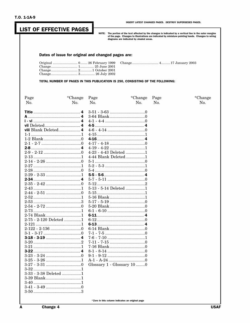
LIST OF EFFECTIVE PAGESNOTE: The portion of the text affected by the changes is indicated by a vertical line in the outer margins
of the page. Changes to illustrations are indicated by miniature pointing hands. Changes to wiringdiagrams are indicated by shaded areas.
Dates of issue for original and changed pages are:
Original ........................... 0........ 26 February 1999 Change............................. 4..........17 January 2003Change............................. 1............... 25 June 2001Change............................. 2.............1 October 2001Change............................. 3................ 26 July 2002
TOTAL NUMBER OF PAGES IN THIS PUBLICATION IS 290, CONSISTING OF THE FOLLOWING:
Page *Change Page *Change Page *ChangeNo. No. No. No. No. No.
Title ......................................... 4 3-51 - 3-63 ...............................0A .............................................. 4 3-64 Blank...............................0i - vi ......................................... 4 4-1 - 4-4 ...................................0vii Deleted............................... 4 4-5 ........................................... 4viii Blank Deleted................... 4 4-6 - 4-14 .................................01-1 ............................................1 4-15 ..........................................11-2 Blank.................................0 4-16 ......................................... 42-1 - 2-7 ...................................0 4-17 - 4-18 ...............................02-8 ........................................... 4 4-19 - 4-22 ...............................12-9 - 2-12 .................................0 4-23 - 4-43 Deleted .................12-13 ..........................................1 4-44 Blank Deleted.................12-14 - 2-26 ...............................0 5-1 ............................................02-27 ..........................................1 5-2 - 5-3 ...................................12-28 ..........................................0 5-4 ............................................02-29 - 2-33 ...............................1 5-5 - 5-6................................... 42-34 ......................................... 4 5-7 - 5-11 .................................02-35 - 2-42 ...............................0 5-12 ..........................................22-43 ..........................................1 5-13 - 5-14 Deleted .................12-44 - 2-51 ...............................0 5-15 ..........................................12-52 ..........................................1 5-16 Blank...............................12-53 ..........................................3 5-17 - 5-19 ...............................02-54 - 2-72 ...............................0 5-20 Blank...............................02-73 ..........................................1 6-1 - 6-10 .................................02-74 Blank...............................1 6-11 ......................................... 42-75 - 2-120 Deleted ...............1 6-12 ..........................................02-121 ........................................1 6-13 ......................................... 42-122 - 2-136 ...........................0 6-14 Blank...............................03-1 - 3-17 .................................0 7-1 - 7-5 ...................................03-18 - 3-19 .............................. 4 7-6 - 7-10 .................................13-20 ..........................................2 7-11 - 7-15 ...............................03-21 ..........................................1 7-16 Blank...............................03-22 ......................................... 4 8-1 - 8-14 .................................03-23 - 3-24 ...............................0 9-1 - 9-12 .................................03-25 - 3-26 ...............................1 A-1 - A-24 ................................03-27 - 3-31 ...............................0 Glossary 1 - Glossary 10 ........03-32 ..........................................13-33 - 3-38 Deleted .................13-39 Blank...............................13-40 ..........................................13-41 - 3-49 ...............................03-50 ..........................................3
*Zero in this column indicates an original page
A Change 4 USAF

T.O. 1-1A-9
TABLE OF CONTENTS
Section Page Section Page
I INTRODUCTION..................................................... 1-1 2-199 Deleted1-1 PURPOSE ............................................. 1-1 2-200 Deleted
2-201 DeletedII FERROUS (STEEL) ALLOYS................................. 2-1 2-202 Deleted
2-1 Classification ........................................ 2-1 2-203 Deleted2-2 SAE Numbering System ...................... 2-1 2-216 Deleted2-4 Carbon Steels ........................................ 2-1 2-234 Fabrication of Ferrous2-7 Nickel Steels ......................................... 2-2 Alloys..............................................2-1212-8 Chromium Steels .................................. 2-2 2-292 Steel Surface Finishes...................... 2-1302-9 Chromium - Nickel Steels.................... 2-22-11 Chrome - Vanadium Steels .................. 2-3 III ALUMINUM ALLOYS............................................. 3-12-12 Chrome - Molybdenum 3-1 Classification ........................................ 3-1
Steels ..................................................2-3 3-4 Commercial and Military2-13 Principles of Heat Treat- Designations ......................................3-1
ment of Steels ....................................2-3 3-8 Mechanical Properties.......................... 3-22-14 Hardening ............................................. 2-3 3-16 Physical Properties............................. 3-182-19 Quenching Procedure ........................... 2-4 3-17 Heat Treatment of Alumi-2-26 Tempering (Drawing) ........................... 2-4 num Alloys .......................................3-182-29 Normalizing........................................... 2-5 3-51 Heat Treatment .................................. 3-242-30 Case Hardening .................................... 2-5 3-56 Heat Treating Equipment.................. 3-242-35 Carburizing ........................................... 2-6 3-70 Fabrication .......................................... 3-282-41 Cyaniding .............................................. 2-7 3-73 Forming Sheet Metal.......................... 3-282-42 Nitriding................................................ 2-7 3-96 Deleted2-43 Heat Treating Equipment.................... 2-7 3-97 Deleted2-48 Heat Control, Furnace Tem- 3-118 Deleted
peratures Survey and 3-123 DeletedTemperature Measuring 3-131 DeletedEquipment..........................................2-8 3-145 Deleted
2-53 Furnace Control Instru- 3-154 Deletedments Accuracy..................................2-8 3-175 Machining............................................ 3-45
2-55 Salt Bath Control ............................... 2-10 3-179 Cutting Tools for Machin-2-58 Quenching Tanks and ing Aluminum..................................3-45
Liquids..............................................2-10 3-180 Turning................................................ 3-462-60 Heat Treating Procedures.................. 2-10 3-183 Milling-Aluminum .............................. 3-462-68 Hardness Testing................................ 2-11 3-189 Shaping and Planing.......................... 3-492-73 Specification Cross 3-195 Tapping................................................ 3-56
Reference..........................................2-11 3-198 Filing ................................................... 3-562-74 General Heat Treating 3-202 Reaming .............................................. 3-57
Temperatures, Composi- 3-204 Sawing ................................................. 3-57tion (Chemical) and 3-210 Grinding .............................................. 3-58Characteristics of Vari- 3-216 Polishing.............................................. 3-58ous Steel and Steel Alloy ................2-35 3-218 Roughing ............................................. 3-58
2-75 Machining of Steels 3-219 Greasing or Oiling .............................. 3-58(General) ..........................................2-60 3-221 Buffing ................................................ 3-59
2-81 Machining Corrosion Re- 3-223 Hardness Testing................................ 3-59sisting Steel .....................................2-65 3-226 Non-Destructive
2-117 Deleted Testing/Inspection ...........................3-592-128 Deleted 3-228 Anodizing Process for In-2-131 Deleted spection of Aluminum2-135 Deleted Alloy Parts .......................................3-592-147 Deleted 3-231 Aluminum Alloy Effects on2-152 Deleted Scratches on Clad Alu-2-168 Deleted minum Alloy ....................................3-592-184 Deleted 3-233 Allowable Defects................................ 3-592-186 Deleted 3-234 Harmful Scratches.............................. 3-602-195 Deleted
Change 4 i
T.O. 1-1A-9
TABLE OF CONTENTS - Continued
Section Page Section Page
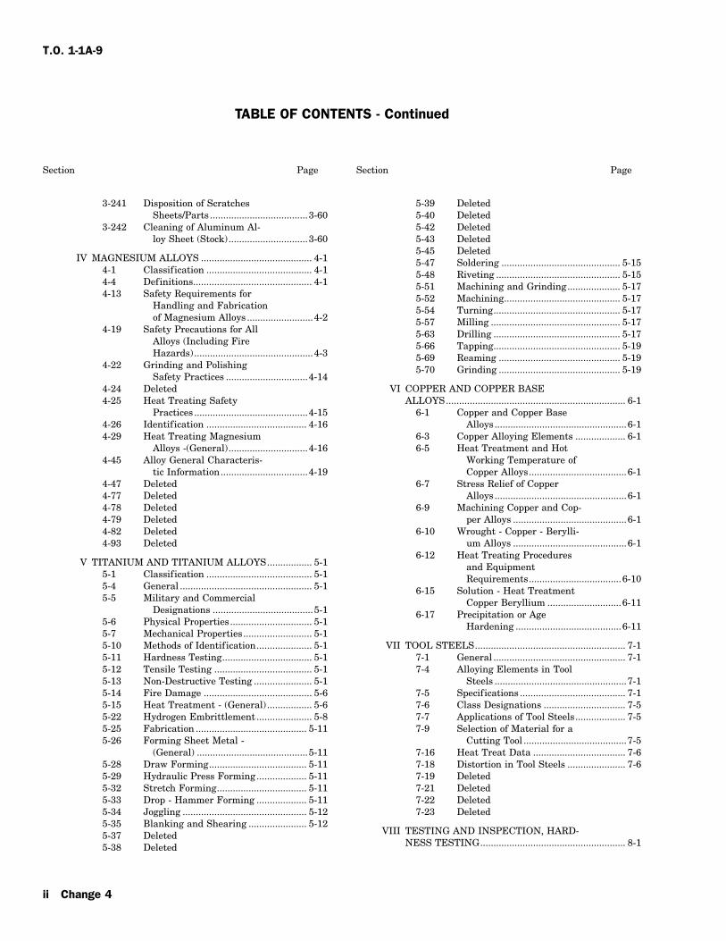
3-241 Disposition of Scratches 5-39 DeletedSheets/Parts .....................................3-60 5-40 Deleted
3-242 Cleaning of Aluminum Al- 5-42 Deletedloy Sheet (Stock)..............................3-60 5-43 Deleted
5-45 DeletedIV MAGNESIUM ALLOYS .......................................... 4-1 5-47 Soldering ............................................. 5-15
4-1 Classification ........................................ 4-1 5-48 Riveting ............................................... 5-154-4 Definitions............................................. 4-1 5-51 Machining and Grinding.................... 5-174-13 Safety Requirements for 5-52 Machining............................................ 5-17
Handling and Fabrication 5-54 Turning................................................ 5-17of Magnesium Alloys .........................4-2 5-57 Milling ................................................. 5-17
4-19 Safety Precautions for All 5-63 Drilling ................................................ 5-17Alloys (Including Fire 5-66 Tapping................................................ 5-19Hazards) .............................................4-3 5-69 Reaming .............................................. 5-19
4-22 Grinding and Polishing 5-70 Grinding .............................................. 5-19Safety Practices ...............................4-14
4-24 Deleted VI COPPER AND COPPER BASE4-25 Heat Treating Safety ALLOYS.................................................................... 6-1
Practices ...........................................4-15 6-1 Copper and Copper Base4-26 Identification ...................................... 4-16 Alloys..................................................6-14-29 Heat Treating Magnesium 6-3 Copper Alloying Elements ................... 6-1
Alloys -(General)..............................4-16 6-5 Heat Treatment and Hot4-45 Alloy General Characteris- Working Temperature of
tic Information.................................4-19 Copper Alloys.....................................6-14-47 Deleted 6-7 Stress Relief of Copper4-77 Deleted Alloys..................................................6-14-78 Deleted 6-9 Machining Copper and Cop-4-79 Deleted per Alloys ...........................................6-14-82 Deleted 6-10 Wrought - Copper - Berylli-4-93 Deleted um Alloys ...........................................6-1
6-12 Heat Treating ProceduresV TITANIUM AND TITANIUM ALLOYS................. 5-1 and Equipment
5-1 Classification ........................................ 5-1 Requirements...................................6-105-4 General .................................................. 5-1 6-15 Solution - Heat Treatment5-5 Military and Commercial Copper Beryllium ............................6-11
Designations ......................................5-1 6-17 Precipitation or Age5-6 Physical Properties............................... 5-1 Hardening ........................................6-115-7 Mechanical Properties.......................... 5-15-10 Methods of Identification..................... 5-1 VII TOOL STEELS......................................................... 7-15-11 Hardness Testing.................................. 5-1 7-1 General .................................................. 7-15-12 Tensile Testing ..................................... 5-1 7-4 Alloying Elements in Tool5-13 Non-Destructive Testing ...................... 5-1 Steels ..................................................7-15-14 Fire Damage ......................................... 5-6 7-5 Specifications ........................................ 7-15-15 Heat Treatment - (General) ................. 5-6 7-6 Class Designations ............................... 7-55-22 Hydrogen Embrittlement ..................... 5-8 7-7 Applications of Tool Steels................... 7-55-25 Fabrication .......................................... 5-11 7-9 Selection of Material for a5-26 Forming Sheet Metal - Cutting Tool .......................................7-5
(General) ..........................................5-11 7-16 Heat Treat Data ................................... 7-65-28 Draw Forming..................................... 5-11 7-18 Distortion in Tool Steels ...................... 7-65-29 Hydraulic Press Forming................... 5-11 7-19 Deleted5-32 Stretch Forming.................................. 5-11 7-21 Deleted5-33 Drop - Hammer Forming ................... 5-11 7-22 Deleted5-34 Joggling ............................................... 5-12 7-23 Deleted5-35 Blanking and Shearing ...................... 5-12
VIII TESTING AND INSPECTION, HARD-5-37 DeletedNESS TESTING....................................................... 8-15-38 Deleted
ii Change 4

T.O. 1-1A-9
TABLE OF CONTENTS - Continued
Section Page Section Page
8-1 General .................................................. 8-1 IX HEAT TREATMENT ............................................... 9-18-3 Methods of Hardness 9-1 General .................................................. 9-1
Testing................................................8-1 9-9 Special Heat Treatment8-5 Brinell Hardness Test .......................... 8-1 Information ........................................9-18-8 Rockwell Hardness Test....................... 8-1 9-11 Tint Test for Determining8-15 Vickers Pyramid Hardness Coating Removal from
Test.....................................................8-4 Nickel Base and Cobalt Base8-18 Shore Scleroscope Hardness Alloys..................................................9-1
Test.....................................................8-8 9-13 Titanium Alloy Parts............................ 9-38-20 Testing with the 9-16 Solution, Stabilization, or
Scleroscope .........................................8-9 Precipitation Heat Treatment ..........9-38-21 Tensile Testing ..................................... 8-9 9-38 Stress-Relief After Welding ................. 9-88-22 Decarburization 9-59 Local Stress-Relief .............................. 9-11
Measurement .....................................8-9 9-68 Description of Methods ...................... 9-118-24 Hardness Method................................ 8-10
A Supplemental Data ..................................................A-18-27 Nondestructive InspectionMethods............................................8-14 Glossary ...............................................................GLS 1
8-33 Chemical Analysis .............................. 8-148-34 Spectrochemical Analysis................... 8-14
LIST OF ILLUSTRATIONS
Figure Title Page Figure Title Page
2-1 Number and Distribution of 4-2 DeletedThermocouples............................................2-9 4-3 Deleted
2-2 Deleted 4-4 Deleted2-3 Deleted 8-1 Brinell Hardness Tester................................ 8-42-4 Stretch Forming......................................... 2-127 8-2 Rockwell Hardness Tester ............................ 8-52-5 Surface Roughness .................................... 2-135 8-3 Attachments for Rockwell Tester ................. 8-63-1 Head to Alloy Identification 8-4 Vickers Pyramid Hardness Tester ............... 8-7
Method ......................................................3-20 8-5 Standard Pyramid Diamond3-2 Drill Designs and Recommended Indentor.......................................................8-8
Cutting Angles..........................................3-55 8-6 Shore Scleroscope .......................................... 8-84-1 Typical Dust Collectors for 8-7 Test Specimens ............................................ 8-11
Magnesium................................................4-22
LIST OF TABLES
Number Title Page Number Title Page
2-1 Soaking Periods for Hardening 2-4 Machinability Rating of VariousNormalizing and Annealing Metals........................................................2-61(Plain Carbon Steel).................................2-10 2-5 Conversion of Surface Feet Per
2-2 Specification Cross Reference .................... 2-12 Minute (SFM) to Revolutions2-3 Cutting Speeds and Feeds for Per Minute (RPM)....................................2-63
SAE 1112 Using Standard 2-6 Tool Correction Chart ................................. 2-64High Speed Tools .....................................2-61
Change 4 iii
T.O. 1-1A-9
LIST OF TABLES - Continued
Number Title Page Number Title Page
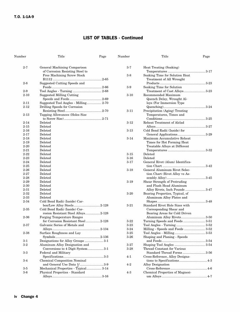
2-7 General Machining Comparison 3-7 Heat Treating (Soaking)of Corrosion Resisting Steel to Temperatures ...........................................3-17Free Machining Screw Stock 3-8 Soaking Time for Solution HeatB1112 ........................................................2-65 Treatment of All Wrought
2-8 Suggested Cutting Speeds and Products ....................................................3-23Feeds .........................................................2-66 3-9 Soaking Time for Solution
2-9 Tool Angles - Turning ................................. 2-68 Treatment of Cast Alloys.........................3-232-10 Suggested Milling Cutting 3-10 Recommended Maximum
Speeds and Feeds.....................................2-69 Quench Delay, Wrought Al-2-11 Suggested Tool Angles - Milling................. 2-70 loys (For Immersion Type2-12 Drilling Speeds for Corrosion Quenching)................................................3-24
Resisting Steel..........................................2-70 3-11 Precipitation (Aging) Treating2-13 Tapping Allowances (Holes Size Temperatures, Times and
to Screw Size) ...........................................2-71 Conditions.................................................3-252-14 Deleted 3-12 Reheat Treatment of Alclad2-15 Deleted Alloys.........................................................3-272-16 Deleted 3-13 Cold Bend Radii (Inside) for2-17 Deleted General Applications................................3-292-18 Deleted 3-14 Maximum Accumulative Reheat2-19 Deleted Times for Hot Forming Heat2-20 Deleted Treatable Alloys at Different2-21 Deleted Temperatures ...........................................3-322-22 Deleted 3-15 Deleted2-23 Deleted 3-16 Deleted2-24 Deleted 3-17 General Rivet (Alum) Identifica-2-25 Deleted tion Chart .................................................3-422-26 Deleted 3-18 General Aluminum Rivet Selec-2-27 Deleted tion Chart (Rivet Alloy vs As-2-28 Deleted sembly Alloy) ............................................3-452-29 Deleted 3-19 Shear Strength of Protruding2-30 Deleted and Flush Head Aluminum2-31 Deleted Alloy Rivets, Inch Pounds .......................3-472-32 Deleted 3-20 Bearing Properties, Typical, of2-33 Deleted Aluminum Alloy Plates and2-34 Cold Bend Radii (Inside) Car- Shapes.......................................................3-48
bon/Low Alloy Steels..............................2-128 3-21 Standard Rivet Hole Sizes with2-35 Cold Bend Radii (Inside) Cor- Corresponding Shear and
rosion Resistant Steel Alloys.................2-128 Bearing Areas for Cold Driven2-36 Forging Temperature Ranges Aluminum Alloy Rivets............................3-50
for Corrosion Resistant Steel ................2-128 3-22 Turning Speeds and Feeds ......................... 3-512-37 Galvanic Series of Metals and 3-23 Tool Angles - Turning ................................. 3-52
Alloys.......................................................2-134 3-24 Milling - Speeds and Feeds ........................ 3-522-38 Surface Roughness and Lay 3-25 Tool Angles - Milling................................... 3-53
Symbols...................................................2-136 3-26 Shaping and Planing - Speeds3-1 Designations for Alloy Groups ..................... 3-1 and Feeds..................................................3-543-2 Aluminum Alloy Designation and 3-27 Shaping Tool Angles ................................... 3-54
Conversions to 4 Digit System..................3-1 3-28 Thread Constant for Various3-3 Federal and Military Standard Thread Forms ..........................3-56
Specifications..............................................3-3 4-1 Cross-Reference, Alloy Designa-3-4 Chemical Composition Nominal tions to Specifications................................4-3
and General Use Data 1/ ...........................3-9 4-2 Alloy Designation3-5 Mechanical Properties - Typical................. 3-14 Cross-Reference ..........................................4-63-6 Physical Properties - Standard 4-3 Chemical Properties of Magnesi-
Alloys.........................................................3-16 um Alloys ....................................................4-7
iv Change 4

T.O. 1-1A-9
LIST OF TABLES - Continued
Number Title Page Number Title Page
4-4 Mechanical Properties Magnesi- 6-2 Hot Working and Annealingum Extrusions and Forgings at Temperatures for Copper andRoom Temperature - Typical.....................4-9 Wrought Copper Alloys..............................6-9
4-5 Mechanical Properties Magnesi- 6-3 Typical Stress-Relief Treat-um Alloy Sheet and Plate at ments for Certain Copper Alloys ............6-11Room Temperature - Typical...................4-11 6-4 Standard Machinability Rating
4-6 Mechanical Properties of Mag- of Copper Alloys .......................................6-12nesium Alloy Castings at 6-5 Typical Engineering Properties.................. 6-13Room Temperatures.................................4-12 6-6 Age Hardening
4-7 Physical Properties - Magnesi- Time-Temperature Conditionsum Alloy @ 68 oF......................................4-13 and Material Temper -
4-8 Solution Heat Treating Temper- Designations .............................................6-13atures and Holding Times .......................4-18 7-1 Tool Steel Specifications............................... 7-2
4-9 Artificial Aging (Precipitation 7-2 Chemical Composition, Tool Steel................ 7-3Treatment) ................................................4-19 7-3 Tool Steel Selection ....................................... 7-5
4-10 Deleted 7-4 Tool Steel Hardening and Tem-4-11 Deleted pering Temperatures .................................7-54-12 Deleted 7-5 Forging, Normalizing and An-4-13 Deleted nealing Treatments of Tool and4-14 Deleted Die Steels ....................................................7-74-15 Deleted 7-6 Thermal Treatment for Harden-4-16 Deleted ing and Tempering Tool Steel4-17 Deleted - General ...................................................7-114-18 Deleted 7-7 Comparison of Tool Steel4-19 Deleted Properties..................................................7-144-20 Deleted 8-1 Hardness Conversion Chart ......................... 8-34-21 Deleted 8-2 Rockwell Scales, Loads and Pre-4-22 Deleted fix Letters .................................................8-104-23 Deleted 8-3 Approximate Hardness - Tensile4-24 Deleted Strength Relationship of Car-4-25 Deleted bon and Low Alloy Steels ........................8-124-26 Deleted 9-1 Typical Heat Treatment4-27 Deleted Application..................................................9-14-28 Deleted 9-2 Cross-Index for Solution, Stabili-4-29 Deleted zation or Precipitation Heat4-30 Deleted Treatments .................................................9-44-31 Deleted 9-3 Cross-Index for Stress-Relief5-1 Specification Cross Reference Ti- Heat Treatments ........................................9-9
tanium Alloy ...............................................5-2 A-1 Chemical Symbols .........................................A-15-2 Nominal Mechanical Properties A-2 Decimal Equivalents .....................................A-2
at Room Temperature................................5-7 A-3 Engineering Conversion Factors ..................A-65-3 Heat Treat, Stress Relief and An- A-4 Table of Weights - Aluminum
nealing Temperatures and Times .............5-9 and Aluminum Alloy................................. A-85-4 Recommended Minimum CCLD A-5 Table of Weights - Brass...............................A-9
Bend Radii ................................................5-12 A-6 Table of Weights - Bronze ..........................A-105-5 Deleted A-7 Table of Weights - Copper ..........................A-115-6 Turning Speeds for Titanium A-8 Table of Weights - Iron ...............................A-12
Alloys.........................................................5-18 A-9 Table of Weights - Lead..............................A-125-7 Tool Angles for Alloys ................................. 5-18 A-10 Table of Weights - Magnesium5-8 Speeds and Feeds for Milling ..................... 5-18 and Magnesium Alloy ............................. A-125-9 Angles for Tool Grinding ............................ 5-19 A-11 Table of Weights - Nickel Chro-6-1 Chemical Composition by Trade mium Iron Alloy (Inconel) ...................... A-13
Name...........................................................6-2 A-12 Table of Weights - Nickel Cop-per Alloy................................................... A-13
A-13 Table of Weights - Steel..............................A-13
Change 4 v

T.O. 1-1A-9
LIST OF TABLES - Continued
Number Title Page Number Title Page
A-14 Table of Weights - Zinc ...............................A-16 A-18 Bend Set Back Chart ..................................A-21A-15 Temperature Conversion Chart .................A-17 A-19 Comparative Table of StandardA-16 Standard Bend Radii for 90o Gages........................................................ A-22
Cold Forming-Flat Sheet ........................ A-18 A-20 Melting Points Approximate.......................A-23A-17 Metal Bending and Bend Radii
Bend Allowances Sheet MetalBend Allowances Per Degreeof Bend Aluminum Alloys....................... A-19
vi Change 4

T.O. 1-1A-9
SECTION I
INTRODUCTION
1-1. PURPOSE. 1-4. The information/instruction containedherein are for general use. If a conf lict exists1-2. This is one of a series of technical or engi- between this technical manual and the specificneering technical manuals prepared to assist per- technical manual(s) or other approved data for asonnel engaged in the maintenance and repair of particular weapon, end item, equipment, etc., theAerospace Weapon Systems and Supporting Equip- data applicable to the specific item(s) will government (AGE). Army Personnel: Wherever the text in all cases.of this manual refers to other technical orders
(T.O.’s) for supporting information, refer to compa- 1-5. The use of ‘‘shall’’, ‘‘will’’, ‘‘should’’ andrable Army documents. ‘‘may’’ in this technical manual is as follows:
1-3. This technical manual provides precise data a. Whenever the word ‘‘shall’’ appears, it shallon specific metals to assist in selection, usage and be interpreted to mean that the requirements areprocessing for fabrication and repair. It includes binding.such data as specification cross reference; b. The words ‘‘will’’, ‘‘should’’ and ‘‘may’’, shallapproved designation system for alloys and tem- be interpreted as nonmandatory provisions.pers; temperatures and other controls for heattreatments; mechanical and physical properties c. The word ‘‘will’’ is used to express declara-processing instructions for basic corrosion preven- tion of purpose.tion; forming characteristics; and other informa-
d. The word ‘‘should’’ is used to express non-tion required for general aerospace weapon systemmandatory desired or preferred method ofrepair. Procedures for general foundry practice,accomplishment.sand control, gating and risering of both ferrous
and non-ferrous castings may be obtained from e. The word ‘‘may’’ is used to express anavailable commercial handbooks and/or publica- acceptable or suggested means of accomplishment.tions. Due to the many types, grades, deversified
1-6. Deleteduses and new developments of metal products, itmay not include all data required in some 1-7. WELDING. Information on welding aero-instances and further study and citation of this space metals is contained in NAVAIR 01-1A-34,data will be required. If a requirement exists for T.O. 00-25-252, T.C. 9-238.information not included, a request for assistanceshould be made to WR-ALC, LEM.
Change 1 1-1/(1-2 blank)


T.O. 1-1A-9
SECTION II
FERROUS (STEEL) ALLOYS
2-1. CLASSIFICATION.TYPE OF STEEL NUMERALS2-2. SAE NUMBERING SYSTEM. A numeral
(AND DIGITS)index system is used to identify the compositionsof the SAE steels, which makes it possible to use Nickel-Chromium-Molybdenumnumerals that are partially descriptive of the com- Steelsposition of material covered by such numbers. Thefirst digit indicates the type to which the steel 1.80% nickel; 0.50 and 0.80%belongs; for example ‘‘1’’ indicates a carbon steel; Chromium; 0.25% Molybdenum 43xx‘‘2’’ a nickel steel; and ‘‘3’’ a nickel chromium steel. 0.55% Nickel; 0.50 and 0.65%In the case of the simple alloy steels, the second Chromium; 0.20% Molybdenum 86xxdigit generally indicates the approximate percent- 0.55% Nickel; 0.50 Chromiumage of the predominant alloying element. Usually 0.25% Molybdenum 87xxthe last two or three digits indicate the approxi- 3.25% Nickel; 1.20 Chromiummate average carbon content in ‘‘points’’ or hun- 0.12% Molybdenum 93xxdredths of 1 percent. Thus ‘‘2340’’ indicates anickel steel of approximately 3 percent nickel (3.25 Nickel-Molybdenum Steelsto 3.75) and 0.40 percent carbon (0.38 to 0.43). In 1.75 Percent Nickel; 0.25some instances, in order to avoid oonfusion, it has percent Molybdenum 46xxbeen found necessary to depart from this system of 3.50 Percent Nickel; 0.25identifying the approximate alloy composition of a percent Molybdenum 48xxsteel by varying the second and third digits of thenumber. An instance of such departure is the Chromium Steels 5xxxsteel numbers selected for several of the corrosion Low Chromium 50xx--and heat resisting alloys. Medium Chromium 51xxx
High Chromium 52xxx2-3. The basic numerals for the various types ofCorrosion and HeatSAE steel are:Resisting 514xx and
515xxTYPE OF STEEL NUMERALS(AND DIGITS) Chromium-Vanadium Steel 6xxx
0.80-1.00 percent Chromium,Carbon Steels 1xxx0.10-0.15 Vanadium 61xxPlain Carbon 10xx
Free Cutting (Screw Stock) 11xxSilicon Manganese Steels 9xxx
A Percent Silicon 92xxManganese Steels 13xxLow Alloy, High Tensile 950Boron Intensified xxBxxNickel Chromium Steels 3xxxLeaded Steels xxLxx1.25 Percent Nickel; 0.65
percent Chromium 31xxCorrosion and Heat Resisting 303xx 2-4. CARBON STEELS. Steel containing car-
bon in percentages ranging from 0.10 to 0.30 per-Molybdenum Steels 4xxx cent is classed as low carbon steel. The equivalent
0.25 Percent Molybdenum 40xx SAE numbers range from 1010 to 1030. Steels ofthis grade are used for the manufacture of articlessuch as safety wire, certain nuts, cable bushing,etc. This steel in sheet form is used for secondarystructural parts and clamps and in tubular formfor moderately stressed structura1 parts.
2-5. Steel containing carbon in percentages rang-ing from 0.30 to 0.50 percent is classed as mediumcarbon steel. This steel is especially adaptable formachining, forging, and where surface hardness is
2-1

T.O. 1-1A-9
important. Certain rod ends, light forgings, and 0.45 to 1.25 percent, while the nickel contentparts such as Woodruff keys, are made from SAE ranges from 1 to 2 percent. Both nickel and chro-1035 steel. mium inf luence the properties of steel; nickel
toughens it, while chromium hardens it. Chrome-2-6. Steel containing carbon in percentage rang- nickel steel is used for machined and forged partsing from 0.50 to 1.05 percent is classed as high requiring strength, ductility, toughness and shockcarbon steel. The addition of other elements in resistance. Parts such as crankshafts and con-varying quantities adds to the hardness of this necting rods are made of SAE 3140 steel.steel. In the fully heat-treated condition it is veryhard and will withstand high shear and wear, but 2-10. Chrome-nickel steel containing approxi-little deformation. It has limited use in aircraft mately 18 percent chromium and 8 percent nickelconstruction. SAE 1095 in sheet form is used for is known as corrosion-resistant steel. It is usuallymaking f lat springs and in wire form for making identified as aisi types 301, 302, 303, 304, 304L,coil springs. 309, 316, 316L, 321, 347, 347F or Se, etc., how-
ever; the basic 18-8 chrome-nickel steel is type2-7. NICKEL STEELS. The various nickel 302. The other grades/types have been modifiedsteels are produced by combining nickel with car- by changing or adding alloying elements to thatbon steel. Some benefits derived from the use of contained in the basic alloy. The alloys are variednickel as an alloy in steel are as follows: to obtain the required mechanical properties forsome specific purpose such as improving corrosiona. Lowers the percentage of carbon that isresistance or forming machining, welding charac-necessary for hardening. The lowering of the car-teristics, etc. The following are examples ofbon content makes the steel more ductile and lessvariations:susceptible to uneven stress.
b. Lowers the critical temperature ranges a. 301-Chromium and Nickel (approximate(heating and cooling) and permits the use of lower 0.5 Nickel) is lowered to increase response to coldheating temperatures for hardening. working.
c. Hardening of the nickel alloy steels at mod- b. 302-Basic Type 18 Chromium 8 Nickel.erate rates of cooling has the advantage of lower-
c. 303-Sulfur(s) or Selenium (se) added foring the temperature gradients, reducing internalimproved machining characteristics.stress/warpage and permits deeper/more uniform
hardening. d. 304-Carbon(c) lowered to reduce suscepti-bility to carbide precipitation. This alloy is stilld. The low heat treating temperaturessubject to carbide precipitation from exposure torequired, reduces the danger of overheating, exces-temperatures 800-1500F range and this shall besive grain growth and the consequent developmentconsidered when it is selected for a specificof brittleness.application.
e. The characteristics depth hardening frome. 304L-Carbon(c) lowered for weldingthe addition of nickel to steel as an alloy results in
applications.good mechanical properties after quenching andtempering. At a given strength (except for very f. 309-Cr and Ni higher for additional corro-thin sections/parts) the nickel steels provide sion and scale resistance.greatly improved elastic properties, impact resis-tance and toughness. g. 316-Molybdenum (Mo) added to improve
corrosion resistance and strength.2-8. CHROMIUM STEELS. Chromium steel ishigh in hardness, strength, and corrosion resistant h. 316L-C- lowered for welding applications.properties. SAE 51335 steel is particularly adapta-
i. 321-Titanium (Ti) added to reduce/avoidble for heat-treated forgins which require greatercarbide precipitation (stabilized grade)toughness and strength than may be obtained in
plain carbon steel. It may be used for such arti- j. 347-Columbium(Cb), Tantalum (Ta)- Addedcles as the balls and rollers of anti-friction to reduce/avoid carbide precipitation (stabilizedbearings. grade).2-9. CHROMIUM-NICKEL STEELS. Chro- k. 347F or Se - Sulfur(s) or Selenium (Se)mium and nickel in various proportions mixed added to improve machinability.with steel form the chrome-nickel steels. The gen-eral proportion is about two and one-half times as The chrome-nickel steels are used for a variety ofmuch nickel as chromium. For all ordinary steels applications on aircraft and missiles. In plate andin this group the chromium content ranges from sheet form it is used for f irewalls, surface skin,
2-2

T.O. 1-1A-9
exhaust stacks, heater ducts, gun wells, ammuni- cooling is slow, the carbide particles are relativelytion chutes, clamps, heat shields/def lectors, fair- coarse and few; in this condition the steel is soft.ing, stiffeners, brackets, shims, etc. In bar and If the cooling is rapid, as be quenching in oil orrod it is used to fabricate various fittings, bolts, water, the carbon precipitates as a cloud of verystuds, screws, nuts, couplings, f langes, valve fine carbide particles, which condition is associ-stems/seats, turn-buckles, etc. In wire form it is ated with high hardness of the steel.used for safety wire, cable, rivets, hinge pins,
2-15. At elevated temperatures, the iron matrixscreens/screening and other miscellaneous items.exists in a form called ‘‘austenite’’ which is capableof dissolving carbon in solid solution. At ordinary2-11. CHROME-VANADIUM STEELS. Thetemperatures the iron exists as ‘‘ferrite’’, in whichvanadium content of this steel is approximatelycarbon is relatively insoluble and precipitates; as0.18 percent and the chromium content approxi-described in the preceding paragraph, in the formmately 1.00 percent. Chrome-vanadium steelsof carbide particles. The temperature at whichwhen heat-treated have excellent properties suchthis change from austenite to ferrite begins toas strength, toughness, and resistance to wear andoccur on cooling is called the ‘‘upper critical tem-fatigue. A special grade of this steel in sheet formperature’’ of the steel, and varies with the carboncan be cold-formed into intricate shapes. It can becontent; up to approximately 0.85 percent carbon,folded and f lattened without signs of breaking orthe upper critical temperature is lowered withfailure. Chrome-vanadium steel with mediumincreasing carbon content; from 0.85 to 1.70 per-high carbon content (SAE 6150) is used to makecent carbon the upper critical temperature issprings. Chrome-vanadium steel with high carbonraised with increasing carbon content. Steel thatcontent (SAE 6195) is used for ball and rollerhas been heated to its upper critical point willbearings.harden completely if rapidly quenched; however, in
2-12. CHROME - MOLYBDENUM STEELS. practice it is necessary to exceed this temperatureMolybdenum in small percentage is used in combi- by/from approximately 28o to 56oC (50o to 100oF)nation with chromium to form chrome-molybde- to insure thorough heating of the inside of thenum steel; this steel has important applications in piece. If the upper critical temperature isaircraft. Molybdenum is a strong alloying element, exceeded too much, an unsatisfactory coarse grainonly 0.15 to 0.25percent being used in the chrome- size will be developed in the hardened steel.molybdenum steels; the chromium content varies
2-16. Successful hardening of steel will largelyfrom 0.80 to 1.10 percent. Molybdenum is verydepend upon the following factors after steel hassimiliar to tungsten in its effect on steel. In somebeen selected which has harden ability desires:instances it is used to replace tungsten in cutting
tools, however; the heat treat characteristic varies. a. Control over the rate of heating, specifi-The addition of up to 1% molybdenum gives steel a cally to prevent cracking of thick and irregularhigher tensile strength and elastic limit with only sections.a slight reduction in ductility. They are especiallyadaptable for welding and for this reason are used b. Thorough and uniform heating through sec-principally for welded structural parts and assem- tions to the correct hardening temperatures.blies. Parts fabricated from 4130, are used exten-
c. Control of furnace atmosphere, in the casesively in the construction of aircraft, missiles, andof certain steel parts, to prevent scaling andmiscellaneous GSE equipment. The 4130 alloy isdecarburization.used for parts such as engine mounts (recipro-
cating), nuts, bolts, gear structures, support brack- d. Correct heat capacity, viscosity, and tem-ets for accessories, etc. perature of quenching medium to harden ade-
quately and to avoid cracks.2-13. PRINCIPLES OF HEAT TREATMENT OFSTEELS. e. In addition to the preceding factors, the
thickness of the section controls the depth of hard-2-14. HARDENING. At ordinary temperatures, ness for a given steel composition. Very thick sec-the carbon content of steel exists in the form of tions may not harden through because of the lowparticles of iron carbide scattered throughout the rate of cooling at the center.iron matrix; the nature of these carbide particles,i.e., their number, size, and distribution, deter- 2-17. When heating steel, the temperaturemines the hardness and strength of the steel. At should be determined by the use of accurateelevated temperatures, the carbon is dissolved in instruments. At times, however, such instrumentsthe iron matrix and the carbide-particles appear are not available, and in such cases, the tempera-only after the steel has cooled through its ‘‘critical ture of the steel may be judged approximately bytemperature’’ (see paragraph 2-15). If the rate of its color. The accuracy with which temperatures
2-3

T.O. 1-1A-9
may be judged by color depends on the experience 2-20. QUENCHING MEDIUM.of the workman, the light in which the work is
2-21. Oil is much slower in action than water,being done, the character of the scale on the steel,and the tendency of heated steel to warp or crackthe amount of radiated light within the furnace,when quenched may be greatly reduced by its use.and the emissivity or tendency of steel to radiateUnfortunately, parts made from high carbon steelor emit light.will not develop maximum hardness when
2-18. A number of liquids may be used for quenched in oil unless they are quite thin in crossquenching steel. Both the medium and the form of section. In aircraft, however, it is generally usedthe bath depend largely on the nature of the work and is recommended in all cases where it will pro-to be cooled. It is important that a sufficient duce the desired degree of hardness.quantity of the medium be provided to allow themetal to be quenched without causing an apprecia- NOTEble change in the temperature of the bath. This is Alloy steels should never be quenchedparticularly important where many articles are to in water.be quenched in succession.
2-22. In certain cases water is used in thequenching of steel for the hardening process. TheNOTEwater bath should be approximately 18oC (65oF),Aerators may be used in the Quenchas extremely cold water is apt to warp or crack theTanks to help dissipate the vaporsteel and water above this temperature will notbarrier.produce the required hardness.
2-19. QUENCHING PROCEDURE. The ten-2-23. A 10%, salt brine (sodium chloride) solutiondency of steel to warp and crack during theis used when higher cooling rates are desired. Aquenching process is diff icult to overcome, and is10% salt brine solution is made by dissolving 0.89due to the fact that certain parts of the article coolpound of salt per gallon of water.more rapidly than others. Whenever the rate of
cooling is not uniform, internal stresses are set up 2-24. For many articles such as milling cutterson the metal which may result in warpage or and similar tools, a bath of water covered by acracking, depending on the severity of the stresses. film of oil is occasionally used. When the steel isIrregularly shaped parts are particularly suscepti- plunged through this oil f ilm a thin coating willble to these conditions although parts of uniform adhere to it, retarding the cooling effect of thesection size are often affected in a similar manner. water slightly, thus reducing the tendency to crackOperations such as forging and machining may set due to contraction.up internal stresses in steel parts and it is there-
2-25. STRAIGHTENING OF PARTS WARPEDfore advisable to normalize articles before attempt-IN QUENCHING. Warped parts must being the hardening process. The following recom-straightened by first heating to below the temper-mendations will greatly reduce the warpinging temperature of the article, and then applyingtendency and should be carefully observed:pressure. This pressure should be continued until
a. An article should never be thrown into the piece is cooled. It is desirable to retemper thequenching media/bath. By permitting it to lie on part after straightening at the straightening tem-the bottom of the bath it is apt to cool faster on perature. No attempt should be made tothe top side than on the bottom side, thus causing straighten hardened steel without heating, regard-it to warp or crack. less of the number of times it has been previously
heated, as steel in its hardened condition cannotb. The article should be slightly agitated inbe bent or sprung cold with any degree of safety.the bath to destroy the coating of vapor which
might prevent it from cooling rapidly. This allows 2-26. TEMPERING (DRAWING). Steel thatthe bath to remove the heat of the article rapidly has been hardened by rapid cooling from a pointby conduction and convection. slightly above its critical range is often harder
than necessary and generally too brittle for mostc. An article should be quenched in such apurposes. In addition, it is under severe internalmanner that all parts will be cooled uniformly andstress. In order to relieve the stresses and reducewith the least possible distortion. For example, athe brittleness or restore ductility the metal isgear wheel or shaft should be quenched in a ver-always ‘‘tempered’’. Tempering consists in reheat-ticle position.ing the steel to a temperature below the critical
d. Irregularly shaped sections should be range (usually in the neighborhood of 600 -immersed in such a manner that the parts of the 1200oF). This reheating causes a coalescence andgreatest section thickness enters the bath first. enlargement of the fine carbide particles produced
2-4
T.O. 1-1A-9
by drastic quenching, and thus tends to soften the bending, and welding. Normalizing may be accom-steel. The desired strength wanted will determine plished in furnaces used for annealing. The arti-the tempering temperature. This is accomplished cles are put in the furnace and heated to a pointin the same types of furnaces as are used for hard- approximately 150o to 225oF above the criticalening and annealing. Less refined methods are temperature of the steel. After the parts havesometimes used for tempering small tools. been held at this temperature for a sufficient time
for the parts to be heated uniformly throughout,2-27. As in the case of hardening, tempering they must be removed from the furnace and cooledtemperatures may be approximately determined in still air. Prolonged soaking of the metal at highby color. These colors appear only on the surface temperatures must be avoided, as this practice willand are due to a thin film of oxide which forms on cause the grain structure to enlarge. The lengththe metal after the temperature reaches 232oC of time required for the soaking temperature will(450oF). In order to see the tempering colors, the depend upon the mass of metal being treated. Thesurface must be brightened. A buff stick consisting optimum soaking time is roughly one-quarter hourof a piece of wood with emery cloth attached is per inch of diameter or thickness.ordinarily used for this purpose. When tempering
2-30. CASE HARDENING. In many instancesby the color method, an open f lame of heated ironit is desirable to produce a hard, wear-resistantplate is ordinarily used as the heating medium.surface or ‘‘case’’ over a strong, tough core. Treat-Although the color method is convenient, it shouldment of this kind is known as ‘‘case hardening’’.not be used unless adequate facilities for determin-This treatment may be accomplished in severaling temperature are not obtainable. Temperingways, the principal ways being carburizing, cya-temperatures can also be determined by the use ofniding, and nitriding.crayons of known melting point. Such crayons are
commercially available for a wide range of temper- 2-31. Flame Hardening/Softening. Surface hard-atures under the trade name of ‘‘Tempilstiks’’. The ening/softening by applying intense heat (such asabove method may be used where exact properties that produced by an Oxy-Acetylene f lame) can beafter tempering is not too important such as for accomplished on almost any of the medium carbonblacksmith work. The most desireable method for or alloys steel, i.e. 1040, 1045, 1137, 1140 etc.general aeronautical use, is to determine tempera- The parts are surface hardened, by applying atures by hardness checks, and subsequent adjust- reducing f lame (An Oxidizing f lame should neverments made as necessary to obtain the properties be used) at such a rate, that the surface is rapidlyrequired. For recommended tempering tempera- heated to the proper quenching temperature fortures see heat treat data for material/composition the steel being treated. Following the applicationinvolved. of the heat, the part is quenched by a spraying of
water/oil rapidly. The fast quench hardens the2-28. Steel is usually subjected to the annealing steel to the depth that the hardening temperatureprocess for the following purposes: has penetrated below the surface. The actual hard-ness resulting will depend on the rate of coolinga. To increase its ductility by reducing hard-from the quenching temperature. In hardening byness and brittleness.this method the shape and size/mass of the partmust be considered. Most operations will requireb. To refine the crystalline structure andspecial adapted spray nozzles to apply the quench-remove stresses. Steel which has been cold-ing media, which is usually water. Normally,worked is usually annealed so as to increase itsf lame hardening will produce surface hardnessductility. However, a large amount of cold-drawnhigher than can be obtained by routine furnacewire is used in its cold-worked state when veryheating and quenching, because surface can behigh yield point and tensile strength are desiredcooled at a faster rate. If a combination of highand relatively low ductility is permissible, as instrength core and surface is required some of thespring wire, piano wire, and wires for rope andmedium carbon alloy steels can be heat treatedcable. Heating to low temperatures, as in solder-and subsequently surface hardened by the f lameing, will destroy these properties. However, rapidmethod.heating will narrow the affected area.
NOTEc. To soften the material so that machining,forming, etc., can be performed. This method is not adapted for sur-
face hardening of parts for use in crit-2-29. NORMALIZING. Although involving a ical applications.slightly different heat treatment, normalizing maybe classed as a form of annealing. This process 2-32. Surface softening is accomplished by heat-also removes stresses due to machining, forging, ing the surface to just below the temperature
2-5

T.O. 1-1A-9
required for hardening and allowing the material 2-38. Solid, liquid, and gas carburizing methodsare employed.to cool (in air) naturally. This method is some-
times used to soften material that has been hard-a. The simplest method of carburizing con-ened by frame cutting. Often it is necessary to
sists of soaking the parts at an elevated tempera-apply the heat in short intervals to preventture while in contact with solid carbonaceousexceeding the hardening temperature.material such as wood charcoal, bone charcoal andcharred leather.2-33. Induction. Hardening/Heating. The induc-
tion method of heating can be used to surfaceb. Liquid carburizing consists of immersingharden steels, in a manner similar to that used for
the parts in a liquid salt bath, heated to thef lame hardening. The exception is that the heatproper temperature. The carbon penetrates thefor hardening is produced by placing the part in asteel as in the solid method producing the desiredmagnetic f ield (electrical) specifically designed forcase.the purpose. Parts hardened (surface) by this
method will be limited to capability and size of c. Gas carburizing consists of heating theloop/coil used to produce the magnetic f ield. parts in a retort and subjecting them to a carbona-
ceous gas such as carbon monoxide or the common2-34. In some instances the induction method fuel gases. This process is particularly adaptablecan be used to deep harden; the extent will depend to certain engine parts.on exposure/dwell time, intensity of the magneticfield, and the size of the part to be treated. 2-39. When pack carburizing, the parts are
packed with the carburizing material in a vented2-35. CARBURIZING. At elevated tempera- steel container to prevent the solid carburizingtures iron can react with gaseous carbon com- compound from burning and to retain the carbonpounds to form iron carbide. By heating steel, monoxide and dioxide gases. Nichrome boxes,while in contact with a carbon-aceous substance, capped pipes of mild steel, or welded mild steelcarbonic gases given off by this material will pene- boxes may be used. Nichrome boxes are most eco-trate the steel to an amount proportional to the nomical for production because they withstand oxi-time and temperature. For example, if mild or dation. Capped pipes of mild steel or welded mildsoft steel is heated to 732oC (1,350oF) in an steel boxes are useful only as substitutes. Theatmosphere of carbonic gases, it will absorb carbon container should be so placed as to allow the heatfrom the gas until a carbon content of approxi- to circulate entirely around it. The furnace mustmately 0.80 percent has been attained at the sur- be brought to the carburizing temperature asface, this being the saturation point of the steel for quickly as possible and held at this heat from 1 tothe particular temperature. By increasing the 16 hours, depending upon the depth of caseheat to 899oC/(1,650oF) the same steel will absorb desired and the size of the work. After carbu-carbon from the gas until a carbon content of rizing, the container should be removed andapproximately 1.1 percent has been attained, allowed to cool in air or the parts removed fromwhich is the saturation point for the increased the carburizing compound and quenched in oil ortemperature. water. The air cooling, although slow, reduces
warpage and is advisable in many cases.2-36. The carburizing process may be applied toboth plain carbon and alloy steels provided they 2-40. Carburized steel parts are rarely usedare within the low carbon range. Specifically, the without subsequent heat treatment, which consistscarburizing steels are those containing not more of several steps to obtain optimum hardness in thethan 0.20 percent carbon. The lower the carbon case, and optimum strength and ductility in thecontent in the steel, the more readily it will core. Grain size of the core and case is refined.absorb, carbon during the carburizing process.
a. Refining the core is accomplished by2-37. The amount of carbon absorbed and the reheating the parts to a point just above the criti-thickness of the case obtained increases with time; cal temperature of the steel. After soaking for ahowever, the carburization progresses more slowly sufficient time to insure uniform heating, theas the carbon content increases during the process. parts are quenched in oil.The length of time required to produce the desireddegree of carburization material used and the tem- b. The hardening temperature for the highperature to which the metal is subjected. It is carbon case is well below that of the core. It is,apparent that, in carburizing, carbon travels therefore, necessary to heat the parts again to theslowly from the outside toward the inside center, critical temperature of the case and quench themand therefore, the proportion of carbon absorbed in oil to produce the required hardness. A soakingmust decrease from the outside to the inside. period of 10 minutes is generally sufficient.
2-6
T.O. 1-1A-9
c. A final stress relieving operation is neces- f laking of the nitrided case. When no distortion issary to minimize the hardening stresses produced permissible in the nitrided part, it is necessary toby the previous treatment. The stress relieving normalize the steel prior to nitriding to remove alltemperature is generally around 350oF. This is strains resulting from the forging, quenching, oraccomplished by heating, soaking until uniformly machining.heated, and cooling in still air. When extreme
2-43. HEAT TREATING EQUIPMENT. Equip-hardness is desired, the temperature should bement necessary for heat treating consists of a suit-carefully held to the lower limit of the range.able means for bringing the metal to the required
2-41. CYANIDING. Steel parts may be surface- temperature measuring and controlling device andhardened by heating while in contact with a quenching medium. Heat may, in some instances,cyanid salt, followed by quenching. Only a thin be supplied by means of a forge or welding torch;case is obtained by this method and it is, there- however, for the treatment required in aircraftfore, seldom used in connection with aircraft con- work, a furnace is necessary. Various jigs and fix-struction or repair. Cyaniding is, however, a rapid tures are sometimes needed for controlling quench-and economical method of case hardening, and ing and preventing warping.may be used in some instances for relatively unim-portant parts. The work to be hardened is 2-44. FURNACES. Heat treating furnaces areimmersed in a bath of molten sodium or potassium of many designs and no one size or type perfectlycyanide from 30 to 60 minutes. The cyanide bath fills every heat treating requirement. The sizeshould be maintained at a temperature to 760oC to and quantity of metal to be treated and the vari-899oC (1,400oF to 1,650oF). Immediately after ous treatments required determine the size andremoval from the bath, the parts are quenched in type of furnace most suitable for each individualwater. The case obtained in this manner is due case. The furnace should be of a suitable type andprincipally to the formation of carbides and design for the purpose intended and should benitrides on the surface of the steel. The use of a capable of maintaining within the working zone aclosed pot and ventilating hood are required for temperature varying not more than + or - 14oCcyaniding, as cyanide vapors are extremely (25oF) for the desired value.poisonous.
2-45. HEAT TREATING FURNACES/BATHS.2-42. NITRIDING. This method of case hard-ening is advantageous due to the fact that a 2-46. The acceptable heating media for heatharder case is obtained than by carburizing. Many treating of steels are air, combusted gases, protec-engine parts such as cylinder barrels and gears tive atmosphere, inert atmosphere or vacuum fur-may be treated in this way. Nitriding is generally naces, molten-fused salt baths, and molten-leadapplied to certain special steel alloys, one of the baths. The heat treating furnaces/baths are ofessential constituents of which is aluminum. The many designs and no one size or type will perfectlyprocess involves the exposing of the parts to fill every heat treating requirement. Furnacesammonia gas or other nitrogenous materials for 20 and baths shall be of suitable design, type andto 100 hours at 950oF. The container in which the construction for purpose intended. Protective andwork and ammonia gas are brought in contact inert atmospheres shall be utilized and circulatedmust be airtight and capable of maintaining good as necessary to protect all surfaces of parts com-circulation and even temperature throughout. The prising the furnace load.depth of case obtained by nitriding is about 0.015inch if heated for 50 hours. The nitriding process 2-47. The design and construction of the heatingdoes not affect the physical state of the core if the equipment shall be such that the furnace/bath ispreceding tempering temperature was 950oF or capable of maintaining within the working zone, atover. When a part is to be only partially treated, any point, a temperature varying not more thantinning of any surface will prevent it from being ±25oF (±14oC) from the required heat treating tem-nitrided. Nitrided surfaces can be reheated to perature, with any charge. After the charge has950oF with out losing any of their hardness, how- been brought up to treating/soaking temperatureever, if heated above that temperature, the hard- all areas of the working zone shall be within theness is rapidly lost and cannot be regained by permissible temperature range specified for theretreatment. Prior to any nitriding treatment, all steel/alloy being heat treated (See Table 2-3, MIL-decarburized metal must be removed to prevent H-6875 or engineering data for material involved).
2-7

T.O. 1-1A-9
NOTE furnaces, a minimum of 9 test thermocouples or 1per 25 cubic feet, whichever is greater, shall beSpecification SAE-AMS-H-6875, Heatused. Bath furnaces shall be tested by use of aTreatment of Steel, will be the controlminimum of 5 test locations or 1 per each 15 cubicdocument for heat treating steelfeet. The locations may be surveys, using suitablematerial to be used on aerospaceprotected multiple or single brake test thermocou-equipment. Where new alloys areples. For distribution of test thermocouples, seeinvolved, it will be necessary toFigure 2-1. Temperature measuring and recordingreview the involved specification orinstruments used for controlling the furnace shallmanufacturer’s engineering or designnot be used to read the temperature of the testdata for the appropriate heat informa-temperature sensing elements.tion (temperature, control, atmos-
phere, times, etc). In case of conf lict 2-52. For all surveys, the furnace or bath tem-the Military/Federal Specification will perature shall be allowed to stabilize at the poten-be governing factor or the conf lict will tial test temperature. The initial survey shall bebe negotiated with the responsible made at the highest and lowest temperatures oftechnical/engineering activities for the furnace specified operating range. Periodicresolution. surveys may be made at a convenient temperature
within the operating range. The temperature of2-48. HEAT CONTROL, FURNACE TEMPERA-all test locations/thermocouples shall be recordedTURES SURVEY AND TEMPERATURE MEA-at 5 minute intervals, starting immediately afterSURING EQUIPMENT.insertion of the test thermocouples in the furnace
2-49. Furnaces/baths shall be equipped with or bath. Reading shall be continued for 1/2-hoursuitable automatic temperature control devices, or more after furnace control thermocouple readsproperly calibrated and arranged, preferably of the within 25oF of original setting. After all the testpotentiometer type to assure adequate control of thermocouples have reached the minimum of thetemperature in all heat-treating zones. The heat treating range, their maximum variationresulting temperature readings shall be within shall not exceed ±25oF (14oC) and shall be within±1.0 percent of the temperature indications of the the specified heat treating temperature range incalibrating equipment. Thermocouples shall be accordance with Specification SAE-AMS-H-6875 orproperly located in the working zones and ade- Table 2-3. If the test indicates that conditions arequately protected from contamination by furnace not satisfactory, the required changes shall beatmospheres by means of suitable protecting made in the furnace and arrangements of thetubes. charge. The furnace control couples shall be cor-
rected for any deviation from the standard electro-2-50. A survey shall be made before placing anymative force (EMF) temperature chart as deter-new furnace in operation, after any change ismined in calibration of the couples.made that may affect operational characteristics,
and semi-annually thereafter to assure conform- 2-53. FURNACE CONTROL INSTRUMENTSance with temperature and control requirement ACCURACY.previously cited. Where furnaces are used only for
2-54. The accuracy of temperature measuring,annealing or stress relieving, an annual surveyrecording and controlling instruments shall bewill be acceptable. The survey may be waived atchecked at regular intervals, not exceeding 3the discretion of the authorized inspector or repre-months or upon request of personnel in charge orsentative provided that the results from previousauthorized (Government) inspector or representa-tests, with the same furnace or bath and sametives. The accuracy of the instrument shall betype of load, show that the temperature and con-made by comparison tests with a standardized pre-trol uniformity is within specified limits. As acision potentiometer type instrument of knownpart of the inspection thermocouples should be(tested) accuracy used with a calibrated thermo-closely inspected for condition and those severelycouple. The test thermocouple shall be locateddeteriorated and of doubtful condition should beapproximately 3 inches from the installed furnacereplaced.thermocouple(s). The temperature for check shall
2-51. The initial and succeeding (semi-annual be at working temperature with a production load.and annual) surveys shall be performed with a If instruments are replaced or not used for 3standard production type atmosphere, controlled if months they shall be checked before use.required. A minimum of 9 test thermocouples or 1per 15 cubic feet, whichever is greater, shall beused for air furnaces except circulating air fur-naces used for tempering only. In the tempering
2-8 Change 4

T.O. 1-1A-9
Figure 2-1. Number and Distribution of Thermocouples
2-9

T.O. 1-1A-9
2-55. SALT BATH CONTROL. Table 2-1. Soaking Periods for Hardening Normalizing andAnnealing (Plain Carbon Steel)
2-56. The bath composition shall be adjusted asfrequently as necessary to prevent objectionableattachment of the steel or alloy to be treated and TIME OFto permit attainment of the desired mechanical HEATING TOproperties of the finished product. The bath will DIAMETER REQUIRED TIME OFbe checked at least once a month. OR TEMPERATURE HOLDING
THICKNESS (APPROX) (APPROX)2-57. Temperature recording should be of theautomatic controlling and recording type, prefera- INCHES HOURS HOURSbly the potentiometer type. Thermocouples shouldbe placed in a suitable protecting tube, unless the 1 and less 3/4 1/2furnace atmosphere is such that undue deteriora- Over 1 1 1/4 1/2tion of the thermocouples will not result. through 2
Over 2 1 3/4 3/42-58. QUENCHING TANKS AND LIQUIDS.through 3Suitable tanks must be provided for quenching
Over 3 2 1/4 1baths. The size of tanks should be sufficientlythrough 4large to allow the liquids to remain approximately
Over 4 2 3/4 1at room temperature. Circulating pumps and cool-through 5ers may be used for maintaining approximately
Over 5 3 1/2 1 1/2constant temperatures where a large amount ofthrough 8quenching is done. The location of these tanks is
very important due to the fact that insufficiently2-63. HARDENING. Temperatures required forrapid transfer from the furnace to the quenchinghardening steel are governed by the chemical com-medium may destroy the effects of the heat treat-position of the steel, previous treatment, handlingment in many instances.equipment, size and shape of piece to be treated.
2-59. The quenching liquids commonly used are Generally, parts of heavy cross section should beas follows: Water at 18oC (65oF), Commercial hardened from the high side of the given tempera-Quenching Oil, and Fish Oil. ture range.
2-60. HEAT TREATING PROCEDURES. 2-64. TEMPERING (DRAWING.) Temperingconsists of heating the hardened steel to the appli-cable temperature holding at this temperature forNOTEapproximately 1 hour per inch of the thickness ofAdditional Heat Treatment informa- the largest section, and cooling in air or quenchingtion is discussed in Section IX. in oil at approximately 27o to 66oC (80o to 150oF).
2-61. INITIAL FURNACE TEMPERATURES. The temperature to be used for tempering of steelIn normalizing, annealing and hardening where depends upon the exact chemical composition,parts are not preheated, the temperature in that hardness, and grain structure obtained by harden-zone of the furnace where works is introduced ing and the method of tempering. The temperingshould be at least 149oC (300oF) below the work- temperatures given are only approximate, and theing temperature at the time of insertion of parts of exact temperature should be determined by hard-simple design. For parts of complicated design ness or tension test for individual pieces. Theinvolving abrupt change of section or sharp cor- final tempering temperatures should not be moreners, the temperature should be at least 260oC than 111oC (200oF) below the tempering, tempera-(500oF) below the working temperature. The fur- ture given. If the center of the section is morenace must be brought to the proper temperature that 1/2-inch from the surface, the tensile strengthgradually. at the center will in general be reduced; therefore,
a lower tempering temperature should be used for2-62. SOAKING PERIODS. The period of soak- sections thicker than 1 inch in order to obtain theing is governed by both the size of the section and required tensile strength.the nature of the steel. Table 2-1 indicates in ageneral way the effect of size on the time for soak- 2-65. ANNEALING. Annealing consists ofing. This table is intended to be used as a guide heating to the applicable temperature, holding atonly and should not be construed as being a man- this temperature for approximately the period ofdatory requirement. It applies only to plain car- time given, and cooling in the furnace to a temper-bon and low alloy steels. ature not higher than 482oC (900oF). The steel
2-10

T.O. 1-1A-9
may then be removed from the furnace and cooled between the tensile strength and hardness is indi-in still air. cated in Table 8-3. This table is to be used as a
guide. It applied only to the plain carbon and low2-66. NORMALIZING. Normalizing consists of alloy steels not to corrosion-resistant, magnet,heating the steel to the applicable temperature, valve, or tool steels. When a narrow range ofholding at this temperature for period of time, hardness is required, the tests to determine theremoving from furnace and cooling in still air. relationship between hardness and strength2-67. CARBURIZING. Carburizing consists of should be made on the actual part. Hardness val-heating the steel packed in a carburizing medium, ues should be within a range of two pointsin a closed container, to the applicable tempera- Rockwell or 20 points Brinell or Vickers. The ten-ture and holding at this temperature for the neces- sile strength-hardness relationship is quite uni-sary period of time to obtain the desired depth of form for parts which are sufficiently large andcase. 1020 steel will require 1 to 3 hours at a rigid to permit obtaining a full depression on acarburizing temperature of 899oC (1650oF) for f lat surface without def lection of the piece. Foreach 1/64 inch of case depth, required. Parts may cylindrical parts of less than 1 inch in diameter,be cooled in the box or furnace to a temperature of the Rockwell reading will be lower than indicatedapproximately 482oC (900oF) then air cool. This in the table for the corresponding tensile strength.treatment leaves the alloy in a relatively soft con- Any process which affects the surface, such asdition and it is then necessary to condition by buffing and plating, or the presence of decarbu-heating and quenching, f irst for core refinement, rized or porous areas and hard spots, will affectfollowed by heating and quenching for case hard- the corresponding relation between hardness andness. Alloy may be quenched directly from the tensile strength. Therefore, these surfaces mustcarburizing furnace, thus producing a hard case be adequately removed by grinding before mea-and a core hardness of Rockwell B67. This treat- surements are made.ment produces a coarse grain in some types ofsteel and may cause excessive distortion. Usually 2-72. In making hardness measurements onthere is less distortion in fine grain steels. The tubular sections, correction factors must be deter-core treatment outlined above refines the grain as mined and applied to the observed readings inwell as hardens. order to compensate for the roundness and def lec-
tion of the tubing under the pressure of the pene-2-68. HARDNESS TESTING.trator. This may be impractical because every
2-69. GENERAL. Hardness testing is an tube size end wall thickness would have a differ-important factor in the determination of the ent factor. As an alternate, the following procedureresults of the heat treatment as well as the condi- may be used: Short lengths may be cut from thetion of the metal before heat treatment and must, tube. A mandrel long enough to extend out boththerefore, be carefully considered in connection ends of the tube and slightly smaller in diameterwith this work. The methods of hardness testing than the inner diameter of the tube is then passedin general use are: the Brinell, Rockwell, Vickers, through the section and the ends supported in ‘‘V’’and Shore Scleroscope. Each of these methods is supports on the hardness tester. Hardness read-discussed in section VIII. ings may then be taken on the tubing.2-70. TENSILE STRENGTH. Tempering tem- 2-73. SPECIFICATION CROSS REFERENCE.peratures listed with the individual steels in Table Table 2-2 is a cross reference index listing the2-3 are offered as a guide for obtaining desired steel and alloy types and the corresponding Fed-tensile and yield strength of the entire cross sec- eral, Military, and aeronautical material specifica-tion. When the physical properties are specified tions for the different configurations. Where twoin terms of tensile strength, but tension tests are or more specifications cover the same material,impractical, hardness tests may be employed using stock material meeting the requirements of a mili-the equivalent hardness values specified in Table tary specification shall be used for all aeronautical8-3. structural items. Some of the specifications listed
in Table 2-2 are for reference only, and are not2-71. HARDNESS-TENSILE STRENGTH RELA-approved for Air Force use.TIONSHIP. The approximate relationship
2-11

T.O. 1-1A-9
Table 2-2. Specification Cross Reference
COMP/ALLOYDESIGN FORM/COMMODITY AMS FEDERAL MILITARY
1005 Rod, welding steel and 5030 MIL-R-908, C1 1cast iron, rod and wire,steel welding (A/Capplication)
1008 Steel, sheet and strip, MIL-S-4174f lat, aluminum coatedlow carbon, MIL-S-4174
1010 Bars, Billets, Blooms, MIL-S-16974Slabs
Bars (General Purpose) QQ-S-633 MIL-S-11310
Wire QQ-W-461
Sheet and Strip 5047 QQ-S-698
Sheet and Strip 5040
Sheet and Strip 5042 QQ-S-698
Sheet and Strip 5044 QQ-S-698
Tubing, Seamless 5050
Tubing, Welded 5053
Rivets 7225
Wire (Carbon) QQ-W-409
Strip (For Small Arms, MIL-S-13468Bullets)
Blooms, Billets, Slabs MIL-S-16788 C1 1
Steel Disks (For Deep MIL-S-13852Drawn Ammunitionitems)
Tubes, Seamless MIL-T-16286 C1 A(Marine Boilerapplication)
Electrodes, Welding MIL-E-6843 C1 E6013
Electrodes, Welding 5031 MIL-E-6843 C1 E6013
Electrodes, Welding MIL-E-18193 ty 60
Rod and Wire (Welding MIL-R-5632 C1 1Low Carbon Steel)
1015, 1016, Bar (General Purpose) 5060 QQ-S-633 (Comp1017, 1018 Bar and Billets C1015-C1019)and 1019
Tube, Seamless/Welded WW-T-731 Comp A
2-12

T.O. 1-1A-9
Table 2-2. Specification Cross Reference - Continued
COMP/ALLOYDESIGN FORM/COMMODITY AMS FEDERAL MILITARY
1015, 1016, Tube, Mechanical QQ-T-830 MT10151017, 1018and 1019(Continued)
Steel - Carbon 5060 QQ-S-633 Comp C1015
Wire (Carbon) QQ-W-409 (Comp 10151019
Wire (Carbon) QQ-W-461
Tubing MIL-T-3520
Steel Disks MIL-S-13852
Plate, Sheet and Strip MIL-S-7809(See Corten)
Sheet and Strip, Bars, QQ-S-640Billets
Blooms, Slabs MIL-S-16974
1020 Bars, Billets, Blooms, MIL-S-16974Slabs
Bars QQ-S-633 MIL-S-3090
Sheet and Strip MIL-S-7952
Wire (Carbon) 5032 QQ-W-461
Wire
Wire (Book Binder) QQ-W-414
Sheet and Strip 5045 QQ-S-698 1020
Plate (Carbon) QQ-S-635
Wire (Carbon) QQ-W-409
Tubing (Automotive) MIL-T-3520
Bars MIL-S-11310
Blooms, Billets, Slabs MIL-S-16788 C1 2
Tubing (Welded) MIL-T-20162 Gr 1
Tubing MIL-T-20169
Steel Disks (For deep MIL-S-13852drawn ammunitionitems)
Sheet and Strip
Tubing (Seamless and QQ-T-830Welded)
Change 1 2-13

T.O. 1-1A-9
Table 2-2. Specification Cross Reference - Continued
COMP/ALLOYDESIGN FORM/COMMODITY AMS FEDERAL MILITARY
1022 Bars and Forgings 5070 QQ-S-633 MIL-S-11310
Plates (Up to 1″) QQ-S-691, C1 A
Wire (Carbon) QQ-W-409
Steel Disk (For deep MIL-S-13852drawn ammunitionitems)
Bars, Billets, Blooms, MIL-S-16974Slabs
Sheet and Strip QQ-S-640
Tubing QQ-S-643
Tubing, Mechanical QQ-T-830
1025 Fittings MIL-F-20236 ty 1
Bars QQ-S-633
Tubing MIL-T-3520
Tubing MIL-T-5066
Castings QQ-S-681, C1 1
Castings QQ-S-681, C1 2
Bars MIL-S-11310
Tubing, Seamless 5075 MIL-T-5066
Tubing, Welded 5077 MIL-T-5066
Wire QQ-W-409
Casting MIL-S-15083 C1 B
Steel Disks MIL-S-13852
Sheet and Strip MIL-S-7952
Tubing QQ-S-643
Plate MIL-P-20167 C1 C
Corten Plate, Sheet and Strip MIL-S-7809(High Str)
NAX AC Sheet, Plate, Bar, 63549115 Billet, Bloom, Strip
1035 Steel, Carbon (Bars, 5080 QQ-S-633 (Bar)Forgings, and Tubings)
Ingot MIL-S-20145 Gr N
Plate MIL-P-20167 C1 A
Bar QQ-S-633
Wire (Carbon) QQ-W-461
2-14

T.O. 1-1A-9
Table 2-2. Specification Cross Reference - Continued
COMP/ALLOYDESIGN FORM/COMMODITY AMS FEDERAL MILITARY
1035 Tubes MIL-T-20141(Continued)
Plate (Carbon) QQ-S-635
Forgings MIL-S-16900
Tubes, Seamless 5082
Plate and Disk MIL-S-3289
Plates (Marine Boiler) QQ-S-691 C1 B
Plates (Marine Boiler) QQ-S-691 C1 C
Shapes, Bar and Plate QQ-S-741 Gr A(Structural)
Wire QQ-W-409
Sheet, Strip QQ-S-640
Forgings (Naval Ship MIL-S-19434, C1 1Board)
Plates and Disks (For MIL-S-3289artillery ammunitioncartridge cases)
Tubes MIL-T-11823
1040 Bars QQ-S-633
Plate (Carbon) QQ-S-635
Castings QQ-S-681, C1 1
Wire QQ-W-409
Bars MIL-S-11310
Blooms, Billets, Bars MIL-S-16974and Slabs
1045 Tubes (Welded) MIL-T-4377
Bars QQ-S-633
Wire (Carbon) QQ-W-461
Ingots MIL-S-20145 Gr P
Plate QQ-S-635
Sheets, Strip, Tubes, QQ-S-640Seamless
Strip MIL-S-303
Strip (For ammunition MIL-S-3039cartridge clips)
1050 Bars QQ-S-633 MIL-S-20137
Plate (Carbon) QQ-S-635
2-15
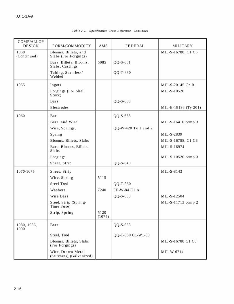
T.O. 1-1A-9
Table 2-2. Specification Cross Reference - Continued
COMP/ALLOYDESIGN FORM/COMMODITY AMS FEDERAL MILITARY
1050 Blooms, Billets, and MIL-S-16788, C1 C5(Continued) Slabs (For Forgings)
Bars, Billets, Blooms, 5085 QQ-S-681Slabs, Castings
Tubing, Seamless/ QQ-T-880Welded
1055 Ingots MIL-S-20145 Gr R
Forgings (For Shell MIL-S-10520Stock)
Bars QQ-S-633
Electrodes MIL-E-18193 (Ty 201)
1060 Bar QQ-S-633
Bars, and Wire MIL-S-16410 comp 3
Wire, Springs, QQ-W-428 Ty 1 and 2
Spring MIL-S-2839
Blooms, Billets, Slabs MIL-S-16788, C1 C6
Bars, Blooms, Billets, MIL-S-16974Slabs
Forgings MIL-S-10520 comp 3
Sheet, Strip QQ-S-640
1070-1075 Sheet, Strip MIL-S-8143
Wire, Spring 5115
Steel Tool QQ-T-580
Washers 7240 FF-W-84 C1 A
Wire Bars QQ-S-633 MIL-S-12504
Steel, Strip (Spring- MIL-S-11713 comp 2Time Fuse)
Strip, Spring 5120(1074)
1080, 1086, Bars QQ-S-6331090
Steel, Tool QQ-T-580 C1-W1-09
Blooms, Billets, Slabs MIL-S-16788 C1 C8(For Forgings)
Wire, Drawn Metal MIL-W-6714(Stitching, (Galvanized)
2-16

T.O. 1-1A-9
Table 2-2. Specification Cross Reference - Continued
COMP/ALLOYDESIGN FORM/COMMODITY AMS FEDERAL MILITARY
1080, 1086, Blooms, Billets, Bars, MIL-S-169741090 Slabs(Continued)
Wire, Comm Quality 5110
Wire, Carbon 5112 QQ-W-470Spring, Music
1095 Bars 5132 QQ-S-633 MIL-S-8559
Bars, Wire MIL-S- 16410 comp 1
Wire, Spring QQ-W-428
Sheet, Strip MIL-S-11713 comp 3
Wire (High Carbon) QQ-W-470
Sheet, Strip 5121 MIL-S-7947 cond AStrip
Sheet, Strip 5122 MIL-S-7947 cond HStrip
Springs 7340
Wire, Spring (For MIL-W-13604small armsapplication)
Blooms, Billets, Slabs MIL-S-16788
Steel Bars, Round, MIL-S-46033Square and Flat forForgings
Strip MIL-S-17919
Bars, Blooms, Billet MIL-S-16974and Slabs
1112 Steel, Carbon, Bars 5010Forging andMechanical Tubing
Bars 5010 QQ-S-633
1117 Steel - Carbon, Bars, 5022Forging andMechanical Tubing
Bars MIL-S-16124, C1 1,comp A
Bars 5022 QQ-S-633
Forgings MIL-S-10520
1137 Steel - Carbon, Bars, 5024Forging andMechanical Tubing
2-17
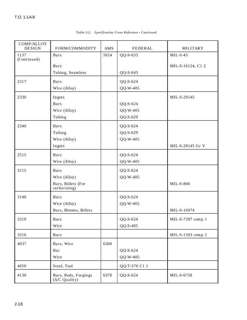
T.O. 1-1A-9
Table 2-2. Specification Cross Reference - Continued
COMP/ALLOYDESIGN FORM/COMMODITY AMS FEDERAL MILITARY
1137 Bars 5024 QQ-S-633 MIL-S-43(Continued)
Bars MIL-S-16124, C1 2
Tubing, Seamless QQ-S-643
2317 Bars QQ-S-624
Wire (Alloy) QQ-W-405
2330 Ingots MIL-S-20145
Bars QQ-S-624
Wire (Alloy) QQ-W-405
Tubing QQ-S-629
2340 Bars QQ-S-624
Tubing QQ-S-629
Wire (Alloy) QQ-W-405
Ingots MIL-S-20145 Gr V
2515 Bars QQ-S-624
Wire (Alloy) QQ-W-405
3115 Bars QQ-S-624
Wire (Alloy) QQ-W-405
Bars, Billets (For MIL-S-866carburizing)
3140 Bars QQ-S-624
Wire (Alloy) QQ-W-405
Bars, Blooms, Billets MIL-S-16974
3310 Bars QQ-S-624 MIL-S-7397 comp 1
Wire QQ-S-405
3316 Bars MIL-S-1393 comp 2
4037 Bars, Wire 6300
Bar QQ-S-624
Wire QQ-W-405
4050 Steel, Tool QQ-T-570 C1 1
4130 Bars, Rods, Forgings 6370 QQ-S-624 MIL-S-6758(A/C Quality)
2-18
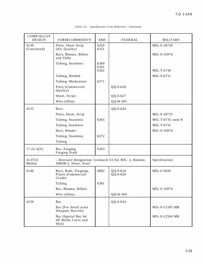
T.O. 1-1A-9
Table 2-2. Specification Cross Reference - Continued
COMP/ALLOYDESIGN FORM/COMMODITY AMS FEDERAL MILITARY
4130 Plate, Sheet Strip 6350 MIL-S-18729(Continued) (A/C Quality) 6351
Bars, Blooms, Billets MIL-S-16974and Slabs
Tubing, Seamless 636063616362 MIL-T-6736
Tubing, Welded MIL-S-6731
Tubing, Mechanical 6371
Plate (Commercial QQ-S-626Quality)
Sheet, Strips QQ-S-627
Wire (Alloy) QQ-W-405
4135 Bars QQ-S-624
Plate, Sheet, Strip MIL-S-18733
Tubing, Seamless 6365 MIL-T-6735 cond N
Tubing, Seamless MIL-T-6735
Bars, Blooms MIL-S-16974
Tubing, Seamless 6372
Tubing
17-22-A(V) Bar, Forging, 6303Forging Stock
4137C0 - Alternate designation: Unimuch UCX2, MX - 2, Rocoloy. Specification:Mellon XMDR-2, Sheet, Steel.
4140 Bars, Rods, Forgings, 6882 QQ-S-624 MIL-S-5626Plates (Commercial QQ-S-626Grade)
Tubing 6381
Bar, Blooms, Billets MIL-S-16974
Wire (Alloy) QQ-W-405
4150 Bar QQ-S-624
Bar (For Small arms MIL-S-11595 MRWeapons Barrels)
Bar (Special Bar for MIL-S-12504 MRAF Bullet Cores andShot)
2-19

T.O. 1-1A-9
Table 2-2. Specification Cross Reference - Continued
COMP/ALLOYDESIGN FORM/COMMODITY AMS FEDERAL MILITARY
52100 Bars, Forgings 6440 MIL-S-7420
Tubing, Mechanical 6441
Ladish D-6-A - Alternate designation, D-6-A-V - and D-6-A-C.
Nitralloy 135 Bar, Forging, Forging Stock 6470 MIL-S-6709, comp ABar
(Nitriding) andForg-ings
Alternate designations, Nitralloy Type G, Modified and ASTM-A355-57TC1 A
Nitralloy 4330 Bars and Forgings Stock MIL-E-8699(Mod)
Nitralloy Bars, Forging 6412- QQ-S-6244337 6475
Tubing, Seamless 6413
Wire (Alloy) QQ-W-405
Ingot MIL-S-20145 Gr U
4340 Plate, Sheet and Strip 6359
Bar, Forging and 6414Tubing
Bar, Forging and 6415 MIL-S-5000Tubing
Bar, Reforging MIL-S-8844 C1 1
Bar QQ-S-624
Bar, Forging and 6428Tubing
Strip and Sheet QQ-S-627
Bar, Rod, Plate MIL-E-21515and Sheet
Wire (Alloy) QQ-W-405
Bars, Blooms, Billets MIL-S-16974
4335 (Mod) Bars, Plates, Sheets MIL-S-21515and Strips
HyTuf Bar, Forging and 6418 MIL-S-7108Mechanical Tubing
4615 Bars QQ-S-624
2-20
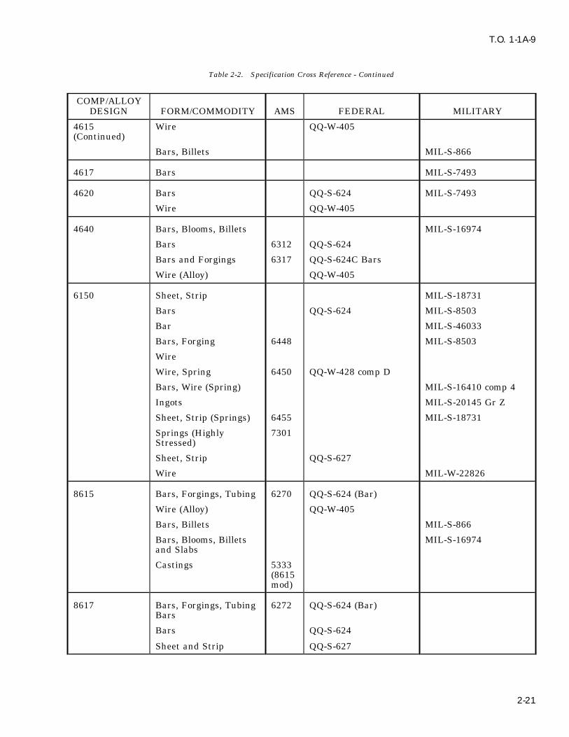
T.O. 1-1A-9
Table 2-2. Specification Cross Reference - Continued
COMP/ALLOYDESIGN FORM/COMMODITY AMS FEDERAL MILITARY
4615 Wire QQ-W-405(Continued)
Bars, Billets MIL-S-866
4617 Bars MIL-S-7493
4620 Bars QQ-S-624 MIL-S-7493
Wire QQ-W-405
4640 Bars, Blooms, Billets MIL-S-16974
Bars 6312 QQ-S-624
Bars and Forgings 6317 QQ-S-624C Bars
Wire (Alloy) QQ-W-405
6150 Sheet, Strip MIL-S-18731
Bars QQ-S-624 MIL-S-8503
Bar MIL-S-46033
Bars, Forging 6448 MIL-S-8503
Wire
Wire, Spring 6450 QQ-W-428 comp D
Bars, Wire (Spring) MIL-S-16410 comp 4
Ingots MIL-S-20145 Gr Z
Sheet, Strip (Springs) 6455 MIL-S-18731
Springs (Highly 7301Stressed)
Sheet, Strip QQ-S-627
Wire MIL-W-22826
8615 Bars, Forgings, Tubing 6270 QQ-S-624 (Bar)
Wire (Alloy) QQ-W-405
Bars, Billets MIL-S-866
Bars, Blooms, Billets MIL-S-16974and Slabs
Castings 5333(8615mod)
8617 Bars, Forgings, Tubing 6272 QQ-S-624 (Bar)Bars
Bars QQ-S-624
Sheet and Strip QQ-S-627
2-21
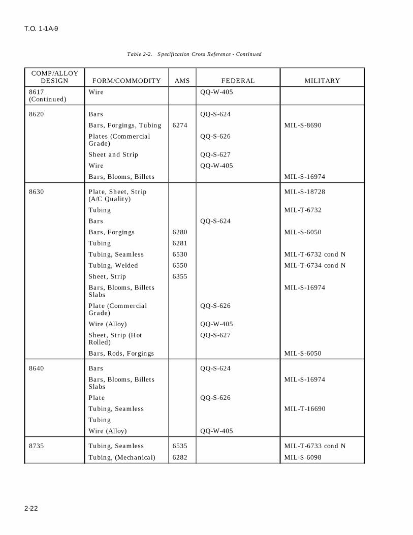
T.O. 1-1A-9
Table 2-2. Specification Cross Reference - Continued
COMP/ALLOYDESIGN FORM/COMMODITY AMS FEDERAL MILITARY
8617 Wire QQ-W-405(Continued)
8620 Bars QQ-S-624
Bars, Forgings, Tubing 6274 MIL-S-8690
Plates (Commercial QQ-S-626Grade)
Sheet and Strip QQ-S-627
Wire QQ-W-405
Bars, Blooms, Billets MIL-S-16974
8630 Plate, Sheet, Strip MIL-S-18728(A/C Quality)
Tubing MIL-T-6732
Bars QQ-S-624
Bars, Forgings 6280 MIL-S-6050
Tubing 6281
Tubing, Seamless 6530 MIL-T-6732 cond N
Tubing, Welded 6550 MIL-T-6734 cond N
Sheet, Strip 6355
Bars, Blooms, Billets MIL-S-16974Slabs
Plate (Commercial QQ-S-626Grade)
Wire (Alloy) QQ-W-405
Sheet, Strip (Hot QQ-S-627Rolled)
Bars, Rods, Forgings MIL-S-6050
8640 Bars QQ-S-624
Bars, Blooms, Billets MIL-S-16974Slabs
Plate QQ-S-626
Tubing, Seamless MIL-T-16690
Tubing
Wire (Alloy) QQ-W-405
8735 Tubing, Seamless 6535 MIL-T-6733 cond N
Tubing, (Mechanical) 6282 MIL-S-6098
2-22
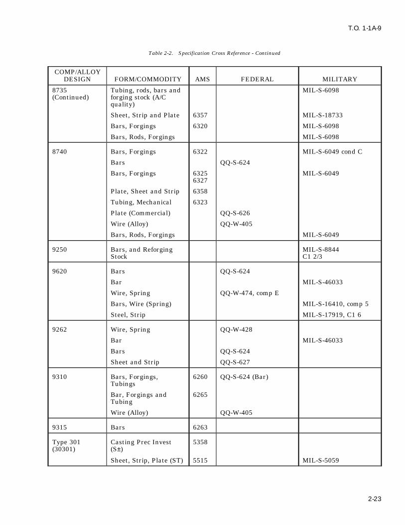
T.O. 1-1A-9
Table 2-2. Specification Cross Reference - Continued
COMP/ALLOYDESIGN FORM/COMMODITY AMS FEDERAL MILITARY
8735 Tubing, rods, bars and MIL-S-6098(Continued) forging stock (A/C
quality)
Sheet, Strip and Plate 6357 MIL-S-18733
Bars, Forgings 6320 MIL-S-6098
Bars, Rods, Forgings MIL-S-6098
8740 Bars, Forgings 6322 MIL-S-6049 cond C
Bars QQ-S-624
Bars, Forgings 6325 MIL-S-60496327
Plate, Sheet and Strip 6358
Tubing, Mechanical 6323
Plate (Commercial) QQ-S-626
Wire (Alloy) QQ-W-405
Bars, Rods, Forgings MIL-S-6049
9250 Bars, and Reforging MIL-S-8844Stock C1 2/3
9620 Bars QQ-S-624
Bar MIL-S-46033
Wire, Spring QQ-W-474, comp E
Bars, Wire (Spring) MIL-S-16410, comp 5
Steel, Strip MIL-S-17919, C1 6
9262 Wire, Spring QQ-W-428
Bar MIL-S-46033
Bars QQ-S-624
Sheet and Strip QQ-S-627
9310 Bars, Forgings, 6260 QQ-S-624 (Bar)Tubings
Bar, Forgings and 6265Tubing
Wire (Alloy) QQ-W-405
9315 Bars 6263
Type 301 Casting Prec Invest 5358(30301) (S±)
Sheet, Strip, Plate (ST) 5515 MIL-S-5059
2-23

T.O. 1-1A-9
Table 2-2. Specification Cross Reference - Continued
COMP/ALLOYDESIGN FORM/COMMODITY AMS FEDERAL MILITARY
Type 301 Sheet, Strip, Plate 5517 MIL-S-5059(30301) (1/4 H)(Continued)
Sheet, Strip, Plate 5518 MIL-S-5059(1/2 H)
Sheet, Strip, Plate 5519 MIL-S-5059(Full H)
Plate, Sheet, Strip QQ-S-766Shape
Wire, (Spring Temper) 5688 QQ-W-423 comp 502
302 Bars (CD to 100000 5636 QQ-S-763 CL 303(30302) tensile)
Bars (CD to 125000 5637 QQ-S-763 C1 302tensile)
Bars, Forgings QQ-S-763, C1 1
Sheet, Strip 5516 MIL-S-5059 comp 302
Plate, Sheet, Strip MIL-S-5059
Pins, Cotter 7210 FF-P-386 Type C
Rivets (18CR 8N:) 7228
Steel, Stainless, Bar MIL-S-862 C1 302and Billets (Reforg-ing Applications)
Bars, Forgings MIL-S-7720
(60302) Steel, Castings 5358
Wire, Annealed QQ-W-423
Castings MIL-S-17509, C1 1
Plate, Sheet, Strip QQ-S-682
Plate, Sheet, Strip QQ-S-766
Wire MIL-W-17481
Lockwashers, Helical 7241 FF-W-84 C1 C
303 Bar, Forging 5640 QQ-S-763
Bar 5738
Bar, Billets, MIL-S-862Reforging
Bars, Forgings MIL-S-7720
Bar, Forging 5641(Swaging)
Bar, Forging 5642
2-24

T.O. 1-1A-9
Table 2-2. Specification Cross Reference - Continued
COMP/ALLOYDESIGN FORM/COMMODITY AMS FEDERAL MILITARY
304 Tubing 5566 MIL-T-6845
Tubing 5567 MIL-T-8504
Castings MIL-S-867 C1 1
Plate, Sheet, Strip MIL-S-4043
Plate MIL-F-20138
Plate, Sheet, Strip QQ-S-766
Castings, Precision 5370Invest
Castings, Sand 5371
Wire 5697 QQ-W-423
Bars, Forgings, 5647Mechanical Tubing
Bar QQ-S-763
Plate, Sheet, Strip 5511 MIL-S-4043
Tubing, Bar, Forging 5639 QQ-S-763 MIL-S-7720
Wire 5697 QQ-W-423
Tubing MIL-T-5695
Bars, Forgings QQ-S-763
Tubing, Seamless 5560 MIL-T-8506
Tubing, Welded 5565 MIL-S-8506
314 Bar, Forging, 5652Mechanical Tubingand Rings
Sheet, Strip, Plate 5522
316 Casting, Investment 5360
Casting, Sand, 5361 MIL-S-867 (C1 III)Centrifugal
Sheet, Strip, Plate 5524 QQ-S-766 MIL-S-5059 comp 316
Tubing, Seamless 5573
Bar, Forging, Tubing 5648 QQ-S-763 MIL-S-7720 comp MCR
Wire, Screen 5698
Wire QQ-W-423
Electrode, Coated, 5691Welded
Bar, Forging (Free 5649Machining)
2-25
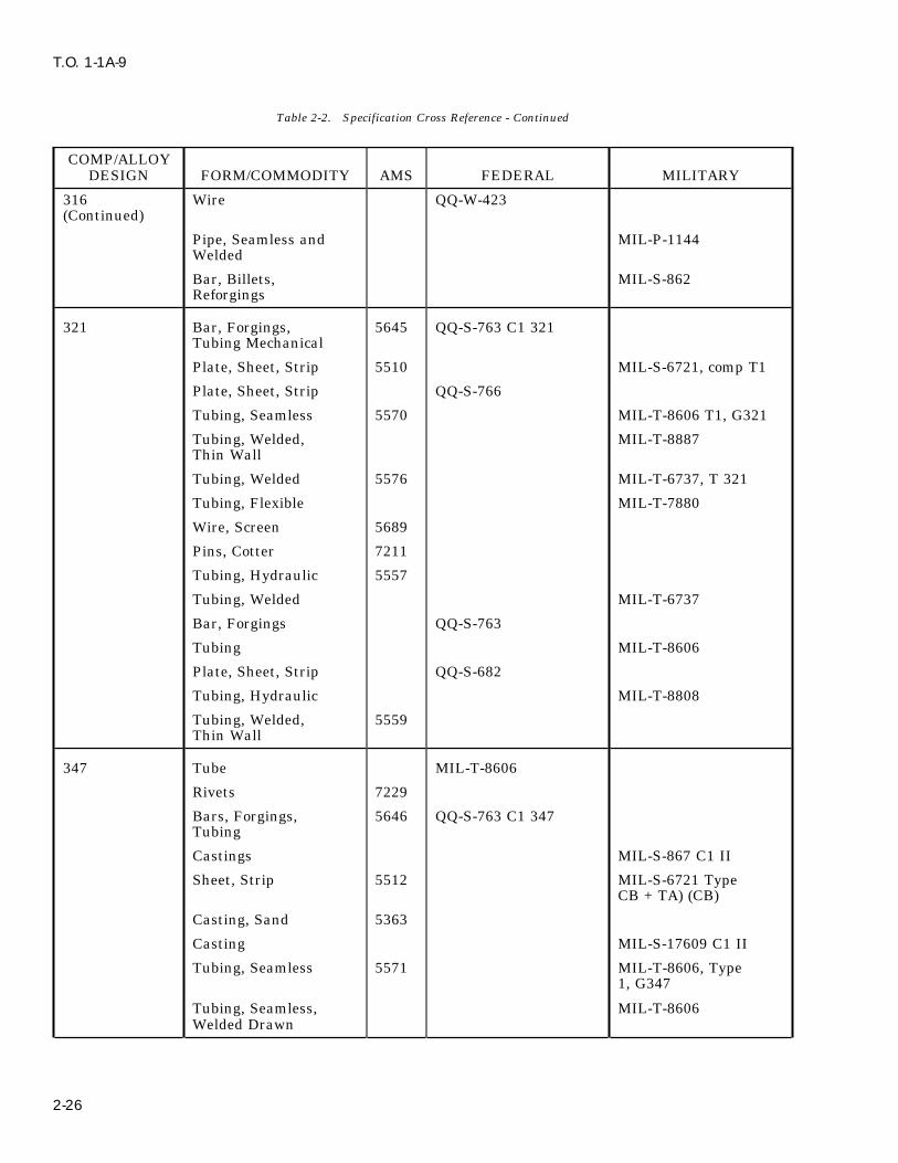
T.O. 1-1A-9
Table 2-2. Specification Cross Reference - Continued
COMP/ALLOYDESIGN FORM/COMMODITY AMS FEDERAL MILITARY
316 Wire QQ-W-423(Continued)
Pipe, Seamless and MIL-P-1144Welded
Bar, Billets, MIL-S-862Reforgings
321 Bar, Forgings, 5645 QQ-S-763 C1 321Tubing Mechanical
Plate, Sheet, Strip 5510 MIL-S-6721, comp T1
Plate, Sheet, Strip QQ-S-766
Tubing, Seamless 5570 MIL-T-8606 T1, G321
Tubing, Welded, MIL-T-8887Thin Wall
Tubing, Welded 5576 MIL-T-6737, T 321
Tubing, Flexible MIL-T-7880
Wire, Screen 5689
Pins, Cotter 7211
Tubing, Hydraulic 5557
Tubing, Welded MIL-T-6737
Bar, Forgings QQ-S-763
Tubing MIL-T-8606
Plate, Sheet, Strip QQ-S-682
Tubing, Hydraulic MIL-T-8808
Tubing, Welded, 5559Thin Wall
347 Tube MIL-T-8606
Rivets 7229
Bars, Forgings, 5646 QQ-S-763 C1 347Tubing
Castings MIL-S-867 C1 II
Sheet, Strip 5512 MIL-S-6721 TypeCB + TA) (CB)
Casting, Sand 5363
Casting MIL-S-17609 C1 II
Tubing, Seamless 5571 MIL-T-8606, Type1, G347
Tubing, Seamless, MIL-T-8606Welded Drawn
2-26
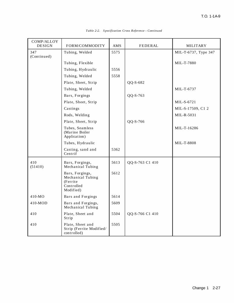
T.O. 1-1A-9
Table 2-2. Specification Cross Reference - Continued
COMP/ALLOYDESIGN FORM/COMMODITY AMS FEDERAL MILITARY
347 Tubing, Welded 5575 MIL-T-6737, Type 347(Continued)
Tubing, Flexible MIL-T-7880
Tubing, Hydraulic 5556
Tubing, Welded 5558
Plate, Sheet, Strip QQ-S-682
Tubing, Welded MIL-T-6737
Bars, Forgings QQ-S-763
Plate, Sheet, Strip MIL-S-6721
Castings MIL-S-17509, C1 2
Rods, Welding MIL-R-5031
Plate, Sheet, Strip QQ-S-766
Tubes, Seamless MIL-T-16286(Marine BoilerApplication)
Tubes, Hydraulic MIL-T-8808
Casting, sand and 5362Centrif
410 Bars, Forgings, 5613 QQ-S-763 C1 410(51410) Mechanical Tubing
Bars, Forgings, 5612Mechanical Tubing(FerriteControlledModified)
410-MO Bars and Forgings 5614
410-MOD Bars and Forgings, 5609Mechanical Tubing
410 Plate, Sheet and 5504 QQ-S-766 C1 410Strip
410 Plate, Sheet and 5505Strip (Ferrite Modified/controlled)
Change 1 2-27

T.O. 1-1A-9
Table 2-2. Specification Cross Reference - Continued
COMP/ALLOYDESIGN FORM/COMMODITY AMS FEDERAL MILITARY
410 Casting Investment 5350(60410)
Casting, Sand 5351 MIL-S-16933 C1 I
Wire QQ-W-423 comp 410
Bars MIL-S-861
Bars, and Billets MIL-S-862(For Reforging)
(51410) Tubing, Seamless 5591
Tubing, Flexible MIL-T-7880
414 Bars, Forgings 5615 QQ-S-763 C1 414
Bars MIL-S-862
416 Bars 5610 QQ-S-763 C1 416 Se(51416F) (Bar)
Bars and Forgings 5610
Bars and Billets(Reforging) MIL-S-862 C1 6
420 Bars and Billets (For MIL-S-862 C1 5Reforging)
Bars and Forgings 5620(Free Mach)
(51420) Bars and Forgings 5621
Bars 5621 QQ-S-763 C1 420
Plate, Sheet and 5506 QQ-S-766 C1 420Strip
Wire QQ-W-423
431 Bars and Billets (For MIL-S-862Reforging)
Bars, Billets, MIL-S-18732Forgings, Tubing
Castings, Sand 5372
Bars, Forgings 5682 QQ-S-763, C1 431
431 MOD Castings, Precision 5353Investment
440 C Bars and Forgings 5630 QQ-S-763, C1 440C
440 A Bars and Forgings 5631 QQ-S-763, C1 440A
2-28
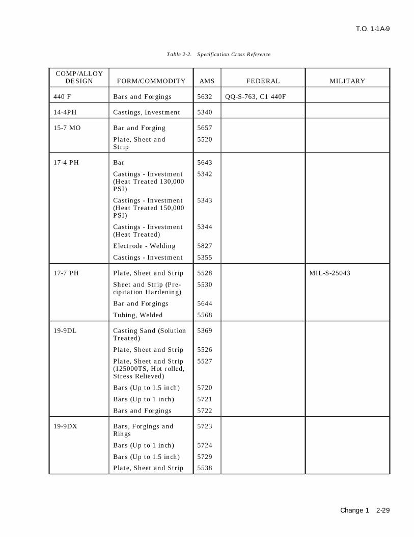
T.O. 1-1A-9
Table 2-2. Specification Cross Reference
COMP/ALLOYDESIGN FORM/COMMODITY AMS FEDERAL MILITARY
440 F Bars and Forgings 5632 QQ-S-763, C1 440F
14-4PH Castings, Investment 5340
15-7 MO Bar and Forging 5657
Plate, Sheet and 5520Strip
17-4 PH Bar 5643
Castings - Investment 5342(Heat Treated 130,000PSI)
Castings - Investment 5343(Heat Treated 150,000PSI)
Castings - Investment 5344(Heat Treated)
Electrode - Welding 5827
Castings - Investment 5355
17-7 PH Plate, Sheet and Strip 5528 MIL-S-25043
Sheet and Strip (Pre- 5530cipitation Hardening)
Bar and Forgings 5644
Tubing, Welded 5568
19-9DL Casting Sand (Solution 5369Treated)
Plate, Sheet and Strip 5526
Plate, Sheet and Strip 5527(125000TS, Hot rolled,Stress Relieved)
Bars (Up to 1.5 inch) 5720
Bars (Up to 1 inch) 5721
Bars and Forgings 5722
19-9DX Bars, Forgings and 5723Rings
Bars (Up to 1 inch) 5724
Bars (Up to 1.5 inch) 5729
Plate, Sheet and Strip 5538
Change 1 2-29

T.O. 1-1A-9
Table 2-2. Specification Cross Reference - Continued
COMP/ALLOYDESIGN FORM/COMMODITY AMS FEDERAL MILITARY
19-9DX Plate, Sheet and Strip, 5539(Continued) (Hot rolled and Stress
Relieved 125,000TS)
Bars, Forgings and 5723Rings
Bars (Up to 1 inch) 5724
Bars (Up to 1.5 inch) 5729
19-9 MOD Electrode, Welding, MIL-E-13080Covered (Armorapplications)
AM350 Bar 5745
Sheet and Strip 5540(Cold rolled)
Sheet and Strip 5548 MIL-S-8840(High TempAnnealed)
Bar and Forgings 5745
Tubing, Seamless 5554
Wire, Welding 5774
Electrode, Coated 5775Wire
AM355 Bar 5743
Castings, Investment 5368
Sheet and Strip 5547 MIL-S-8840
Plate (Solution 5549Heat Treated)
Plate (Equalized and 5594Over-Tempered)
Electrode, Coated 5781Welding
A286 Bars, Forgings, 5734Mechanical Tubing
Bars, Forgings, 5735Mechanical Tubing andRings
2-30 Change 1

T.O. 1-1A-9
Table 2-2. Specification Cross Reference - Continued
COMP/ALLOYDESIGN FORM/COMMODITY AMS FEDERAL MILITARY
A286 Bars, Forgings, 5736(Continued) Mechanical Tubing and
Rings (Sol Treated)
Bars and Forgings and 5737Mechanical Tubing(Annealedand Precip Treated)
Rivets, Steel (Annealed 72351650oF and partiallyprecip treated)
Rene 41 Bars and Forgings 5712(Solution Treated
Bars and Forgings 5713(Solution andPrecip Treated)
Plate Sheet and Strip 5545(Solution HeatTreated)
Greek Castings, Investment 5354Ascoloy
Plate, Sheet and Strip 5508
Bars, Forgings, 5616Mechanical Tubingand Rings
Inconel 600 Wire, Annealed 5687 QQ-W-390
Plate, Sheet and Strip 5540 MIL-N-6840
Bars, Forgings and 5665 MIL-N-6710Rings
Tubing, Seamless 5580 MIL-T-7840
42 Inconel Sheet and Strip 5542 MIL-N-7786Alloy X750
Change 1 2-31

T.O. 1-1A-9
Table 2-2. Specification Cross Reference - Continued
COMP/ALLOYDESIGN FORM/COMMODITY AMS FEDERAL MILITARY
42 Inconel Bars and Forgings 5667Alloy X750(Continued)
Bars and Forgings 5668 MIL-N-8550 Cond E
Inconel X750 Wire, No 1 Temper 5698 JAN-W-562, C1 1
Wire, Spring Temper 5699 JAN-W-562, C1 2
Hastelloy C Castings, Prec 5388Invest
Casting, Sand 5389
Sheet 5530 MIL-N-18088
Bar, Forgings 5750
Hastelloy W Bars and Forgings 5755
Wire 5786 MIL-R-5031, C1 12
Hastelloy X Castings, Alloy Prec 5390Invest
Sheet 5536
Bar and Forgings 5754
Wire 5798
HNM Bars, Billet, Forging, MIL-S-17759Wire
WASP Alloy NONE NONE NONE
MISC STANDARDS/SPECIFICATIONS - METAL PRODUCTS
Steel: Chemical Composition andHardenability Fed Std 66
Metal Test Methods Fed Std 151
Surface Passivation
Corrosion Resistant Steel Parts QQP-35 MIL-STD-753
2-32 Change 1
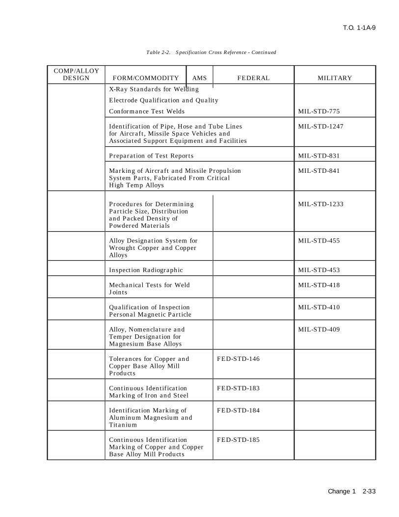
T.O. 1-1A-9
Table 2-2. Specification Cross Reference - Continued
COMP/ALLOYDESIGN FORM/COMMODITY AMS FEDERAL MILITARY
X-Ray Standards for Welding
Electrode Qualification and Quality
Conformance Test Welds MIL-STD-775
Identification of Pipe, Hose and Tube Lines MIL-STD-1247for Aircraft, Missile Space Vehicles andAssociated Support Equipment and Facilities
Preparation of Test Reports MIL-STD-831
Marking of Aircraft and Missile Propulsion MIL-STD-841System Parts, Fabricated From CriticalHigh Temp Alloys
Procedures for Determining MIL-STD-1233Particle Size, Distributionand Packed Density ofPowdered Materials
Alloy Designation System for MIL-STD-455Wrought Copper and CopperAlloys
Inspection Radiographic MIL-STD-453
Mechanical Tests for Weld MIL-STD-418Joints
Qualification of Inspection MIL-STD-410Personal Magnetic Particle
Alloy, Nomenclature and MIL-STD-409Temper Designation forMagnesium Base Alloys
Tolerances for Copper and FED-STD-146Copper Base Alloy MillProducts
Continuous Identification FED-STD-183Marking of Iron and Steel
Identification Marking of FED-STD-184Aluminum Magnesium andTitanium
Continuous Identification FED-STD-185Marking of Copper and CopperBase Alloy Mill Products
Change 1 2-33
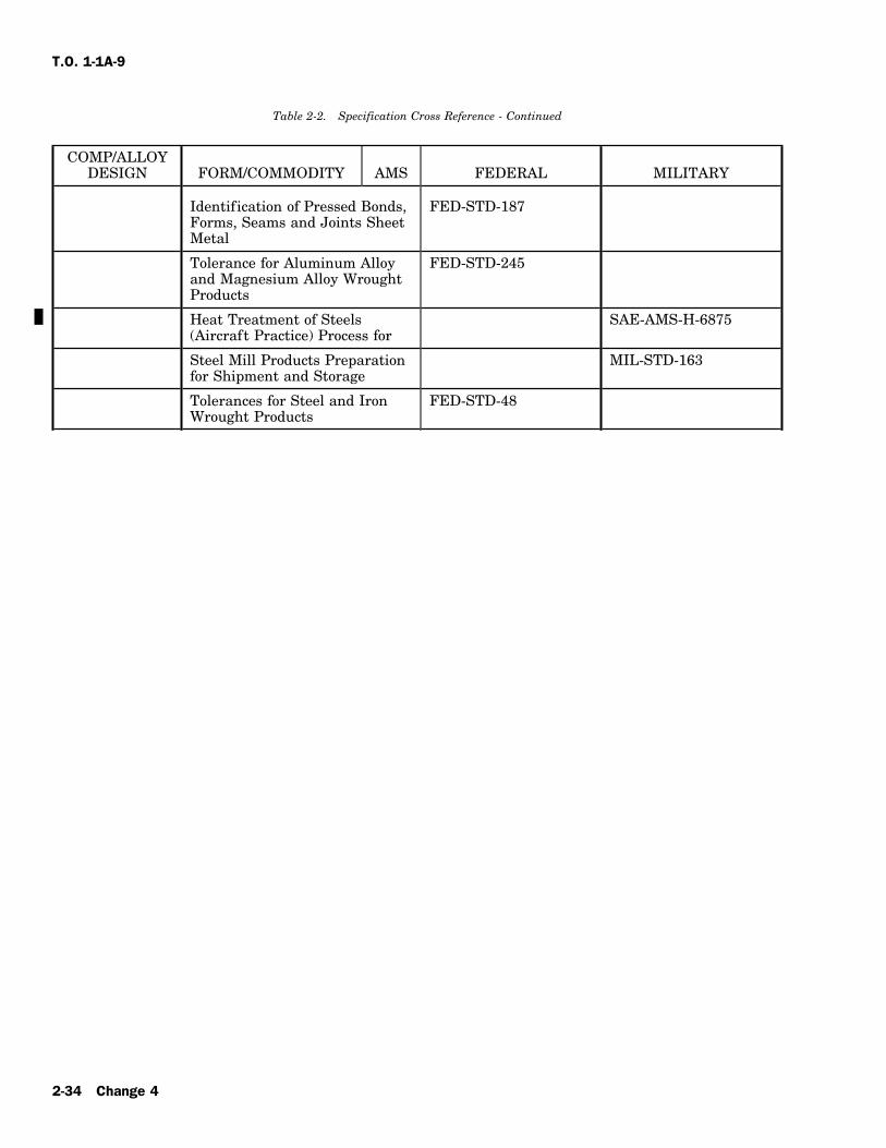
T.O. 1-1A-9
Table 2-2. Specification Cross Reference - Continued
COMP/ALLOYDESIGN FORM/COMMODITY AMS FEDERAL MILITARY
Identification of Pressed Bonds, FED-STD-187Forms, Seams and Joints SheetMetal
Tolerance for Aluminum Alloy FED-STD-245and Magnesium Alloy WroughtProducts
Heat Treatment of Steels SAE-AMS-H-6875(Aircraft Practice) Process for
Steel Mill Products Preparation MIL-STD-163for Shipment and Storage
Tolerances for Steel and Iron FED-STD-48Wrought Products
2-34 Change 4

T.O. 1-1A-9
2-74. GENERAL HEAT TREATING TEMPERATURES, Normalize: 1700oF, air cool.COMPOSITION (CHEMICAL) AND CHARACTERISTICS Anneal: 1600oF, furnace cool.OF VARIOUS STEEL AND STEEL ALLOYS. Carburize: 1600oF, quench in water, oil, or brine.
CARBO-NITRIDING See supplement data for chemical symbols.
1010. Low Carbon steel of this grade is used forHard-manufacture of such articles as safety wire, cer-
Temp Time Case Depth ness Cool Drawtain nuts, cable bushings and threaded rod ends,and other items where cold formability is the pri-
1560 2.5 0.019 62 OQ 350mary requisite. Heat treatment is frequently1650 2.5 0.018 59 OQ 350employed to improve machinability. Welding is
easily accomplished by all common welding For 1560F, use 35NH3d 25CH4 generator gas*.methods. For 1650 use 38NH3 & 24CH4
COMPOSITION RANGE *Gas - American Gas Assoc Class 302.
C% Mn% P% S% Fe% 1022. Low Carbon. This steel is similar in con-0.08-0.13 0.3-0.6 0-0.04 0-0.5 Balance tent and heat treatment requirements to 1020.
Typical applications are case hardened rollerFORMS. See Specification Table 2-2. chains, bearing races, cam shafts, etc.
HEAT TREATMENT COMPOSITION RANGE
C% Mn% Si% P% S% Fe%Normalize: 1650o-1750oF, cool in still air.0.18-0.23 0.7-0.10 0-0.2 0-.04 0-.05 BalanceAnneal: 1650oF.
Harden: 1650o-1750oF, Quench in oil (minimum FORM-SPECIFICATION. See Specification Tablehardness) Water, and Brine (maximum hardness). 2-2.1015. Low Carbon. This material is similar in HEAT TREATMENTcontent and characteristics to 1010. Of low tensile
Normalize: 1700oF, air cool.value, it should not be selected where strength isAnneal: 1600oF, furnace cool.required.Carburize: 1550oF to 1650oF, water quench.
COMPOSITION RANGE Tensile: 130,000 psi.Yield: 78,000 psi.C% Mn% P% S% Fe%
0.13-18 0.3-0.6 0-0.04 0-0.05 Balance 1025. Low Carbon. Typical applications are bolts,machinery, electrical equipment, automotive parts,
FORMS. See Specification Table 2-2. pipe f langes, etc. With this steel no martensite isformed and tempering is not required. This mate-HEAT TREATMENTrial is not generally considered a carburizing type;however, it is sometimes used in this manner forNormalize: 1650o-1750oFlarger sections, or where greater case hardness isAnneal: 1600o-1650oFneeded.Harden: 1650o-1700oF
Quench with water, oil, brine. COMPOSITION RANGE1020. Low Carbon. Because of the carbon range C% Mn% P% S% Fe%this metal has increased strength and hardness 0.22-0.28 0.3-0.6 0-0.04 0-0.05 Balancebut reduced cold formability compared with the
FORM-SPECIFICATION. See Specification Tablelowest carbon group. It f inds wide application2-2.where carburizing is required. It is suitable for
welding and brazing. HEAT TREATMENT
COMPOSITION RANGE Normalize: 1600o-1700oF, furnace cool.Hardening: 1575o-1650oF, water quench.
C% Mn% P% S% Fe% Carburize: 1650o-1700oF, water or brine quench.8-0.23 0.3-0.6 0-0.04 0-0.05 Balance Tempering: 250o-400oF is optional.
Tensile strength: hot rolled 67000, cold rolledFORMS-SPECIFICATIONS. See specifications80000.Table 2-2.Yield strength: hot rolled 45000, cold rolled 68000.
HEAT TREATMENT This steel is readily welded by common welding
2-35
T.O. 1-1A-9
methods. Stress relief anneal 900o-1150oF, air cool, 30 min-Temper: 1150oF for 70,000 psi. utes to 6 hours. Typical room temperatures: tensile
76,500, yield 53,000. For arc welding, use lowCORTEN Low Carbon, Low Alloy. This steel is hydrogen electrodes E6015 (thin gauges) andnot heat treatable, but in the annealed or normal- E7015. For heliarc welding use drawn filler wireized condition it is stronger than plain carbon of MIL-R-5032. Perform spot welding by pulsationsteel, is easily formed, welded and machined. In method for heavier gauges; use post heat cycle foraddition, this alloy is 4-6 times more resistant to lighter gauges.atmospheric corrosion than plain carbon steel.
1035. Medium Carbon. This steel is selectedCOMPOSITION RANGE where higher mechanical properties are neededsince it may be further hardened and strenghtenedC% Cr% Cu% Mn% Ni%by heat treatment or by cold work. Typical appli-0-0.12 0.30-1.25 0.25-0.055 0.2-0.5 0-0.65cations are gears, clutch pedals, f lywheel rings,
Si% P% S% Fe% crank shafts, tools and springs.0.25-0.75 0.07-0.15 0-0.05 Balance
COMPOSITION RANGEHEAT TREATMENTC% Q Mn% P% S% Fe%Normalize: 1650oF, air cool.0.32-0.38 0.6-0.9 0-0.04 0-0.05 BalanceAnneal: 1550oF, furnace cool.FORM-SPECIFICATION. See Specification TableStress relief 1150oF, 1 hour per inch of maximum2-2.section thickness. This alloy cannot be hardened.
Tensile strength, annealed or normalized 67,000 HEAT TREATMENTpsi. Yield strength, annealed or normalized 47,000psi. This alloy is readily welded by the usual gas Normalize: 1575o-1650oF, cool in still air.and arc methods with complete freedom from air Anneal: 1575o-1650oF, 1 hour per 1″ of section,hardening. ASTM A233 or E60 electrodes are rec- (Preheat) Temper at 900oF for 100,000 psi.ommended for shielded arc welding. For gas weld- Spheroidize: 1250o-1375oF.ing, high strength welding rods such as ASTM Harden: 1525o-1600oF, quench in water or oil.A251, CA-25, are recommended. This steel may be (Brine or caustic may also be used for quenching.)resistance welded to itself or other resistance
Weldability is very good by all common weldingweldable ferrous alloys, using the same methodsmethods. Cold formability is poor, but hotapplied to plain carbon steel.formability is excellent. Tensile strength, hot
NAXAC9115 Low Carbon, Low Alloy. This mate- rolled 85,000 psi, cold rolled 92,000 psi, yieldrial is usually in the stress relieved condition. strength, hot rolled 54,000 psi, cold rolled 79,000Moderate strength is maintained with high tough- psi, Brinill 183-201, respectively.ness up to approximately 800oF. Weldability is
1040. Medium Carbon is selected where interme-excellent and it machines better than carbon steelsdiate mechanical properties are needed and mayof the same tensile strengths.be further hardened and strengthened by heat
COMPOSITION RANGE treatment or cold work.C% Cr% Cu% Mn% COMPOSITION RANGE0.1-0.17 0.5-0.75 0-0.35 0.5-0.8
C% Mn% Si% P% S% Fe%Mo% Ni% Si% Zn% 0.37-0.44 0.6-0.9 0-0.2 0-0.04 0-0.05 Balance0.15-0.25 0-0.25 0.6-0.9 0.05-0.15
FORM-SPECIFICATION. See Specification Table-P% S% Fe% 2-2.0-0.04 0-0.04 BalanceHEAT TREATMENTSPECIFICATIONSNormalize: 1575o-1650oF, air cool.AMS FORMAnneal: 1550o-1625oF, furnace cool. (Tensile
6354 Sheet, strip, plate. 79,000 psi, yield 48,000 psi annealed).6440 Wire. Harden: 1500o-1575oF, water or oil quench.
Temper: 1100o-1150oF, to obtain tensile 100,000HEAT TREATMENTpsi, yield 80,000 psi. For tensile 125,000 and yield
Anneal: 1625o-1650oF, furnace cool. 85,000 psi temper at 700oF. Suitable heat treat-Normalize: 1650o-1675oF, air cool. ment is required to permit machining.
2-36

T.O. 1-1A-9
1045. Medium Carbon. Forgings such as connect- FORMS-SPECIFICATIONS. See Specificationing rods, steering arms, axles, axle shafts and Table 2-2.tractor wheels are fabricated from this steel. Not
HEAT TREATMENTrecommended for welding.Normalize: 1550o-1650oF, air cool.COMPOSITION RANGEAnneal: 1550o-1575oF.Harden: 1450o-1550oF, water or oil quench.C% Mn% P% S% Fe%Temper: 1250oF for 100,000 psi tensile, 1050oF for0.43-0.5 0.6-0.9 0-0.04 0-0.04 Balance125,000 tensile, 600oF for 150,000 tensile.
FORMS-SPECIFICATION. See Specification1060. High Carbon. See 1055 for application andTable 2-2.characteristics
HEAT TREATMENTCOMPOSITION RANGE
Normalize: 1575o-1675oF, air cool.C% Mn% P% S% Fe%Anneal: 1550o-1600oF, furnace cool for maximum0.55-0.65 0.6-0.09 0-0.04 0-0.05 Balancesoftness.
Harden: 1475o-1550oF, quench, water or oil. FORM-SPECIFICATION. See Specification TableTemper: 1100oF for tensile 100,000 psi, yield 2-2.65,000 psi.
HEAT TREATMENTTemper: 1000oF for tensile 125,000 psi, yield95,000 psi.
Normalize: 1525o-1625oF, air cool.Anneal: 1500o-1575oF (Tensile 104,000 psi, yield1050. Medium Carbon. This is a medium carbon54,000 psi annealed).type steel with high mechanical properties whichHarden: 1450o-1550oF, water or oil quench.may be further hardened and strengthened byTemper: 1125oF for 130,000 tensile, 80,000 yield.heat treatment or by cold work. Application isTemper: 1025oF for 139,000 tensile, 96,000 yield.similar to 1045. Not recommended for welding.Temper: 925oF for 149,000 tensile, 99,000 yield.
COMPOSITION RANGE1070. High Carbon. See 1055 for application and
C% Mn% P% S% Fe% characteristics. In addition this alloy is used for0.46-0.55 0.6-0.9 0-0.04 0-0.05 Balance f lat springs and wire form as coil springs.
FORMS-SPECIFICATION. See Specification COMPOSITION RANGETable 2-2.
C% Mn% P% S% Fe%HEAT TREATMENT 0.65-0.75 0.6-0.9 0-0.04 0-0.05 Balance
FORM-SPECIFICATION. See Specification TableNormalize: 1550o-1650oF, air cool.2-2.Anneal: 1450o-1525oF, furnace cool (Tensile 90,000
yield 50,000 annealed.)HEAT TREATMENTHarden: 1475o-1550oF, oil or water quench.
Temper: 1250oF for 100,000 psi tensile, 75,000 for Normalize: 1525o-1625oF, air cool, retard coolingyield. rate to prevent hardness.Temper: 1025oF for 125,000 psi tensile, 90,000 for Anneal: 1500o-1575oF, furnace cool.yield. Harden: 1450o-1550oF, water or oil quenchTemper: 700oF for 150,000 psi tensile, 114,000 for (Preheat).yield. Hot Working Temperature: 1550o-1650oF.
Temper: 1250oF for 100,000 psi tensile.1055. High Carbon. Steels of this type (1060, Temper: 1100oF for 125,000 psi tensile.1070, 1080 are in same category) have similiar Temper: 1000oF for 150,000 psi tensile.characteristics and are primarily used wherehigher carbon is needed to improve wear charac- The high carbon content of this steel causes diff i-teristics for cutting edges, as well as for manufac- culties in arc or gas welding processes. Weldingture of springs, etc. Not recommended for by the thermit process is satisfactory. Hot formal-welding. ity is very good at 1550o-1650oF.
COMPOSITION RANGE 1080. High Carbon. See 1055 for applications andcharacteristics.
C% Mn% P% S% Fe%0.50-0.60 0.6-0.9 0-0.04 0-0.05 Balance COMPOSITION RANGE
2-37

T.O. 1-1A-9
C% Mn% P% S% Fe% screws, but not for parts subjected to severe0.75-0.88 0.6-0.9 0-0.04 0-0.05 Balance stresses and shock.
FORM-SPECIFICATION. See Specification Table COMPOSITION RANGE2-2.
C% Mn% P% S% Fe%HEAT TREATMENT 0-0.13 max 0.7-0.9 0.07-0.12 0.16-0.23 Balance
Normalize: 1550o-1650oF, air cool. FORM-SPECIFICATION. See Specification TableAnneal: 1475o-1525oF (Tensile 120,000, yield 2-2.66,000 psi annealed).
HEAT TREATMENTHarden: 1450o-1550oF, quench oil.Temper: 1200oF for 129,000 tensile, 87,000 yield. May be surface hardened by heating in cyanide atTemper: 1100oF for 145,000 tensile, 103,000 yield. 1500o-1650oF, followed by single or double quenchTemper: 900oF for 178,000 tensile, 129,000 yield. and draw. Preheat and soak at 1500oF to 1650oF
and quench in oil or water; tempering is optional.1095. High Carbon. See 1055 for applications. Inaddition these steels are used for f lat spring appli- Tensile strength hot rolled bars 65,000.cations and in wire form as coil springs.
Tensile strength cold drawn 83,000.COMPOSITION RANGE
1117. Carbon (Free Cutting Steel). This materialC% Mn% P% S% Fe% is used where a combination of good machinability0.9-1.03 0.3-0.5 0-0.04 0-0.05 Balance and uniform response to heat treatment is needed.
It is suited for fabrication of small parts which areFORM-SPECIFICATION. See Specification Tableto be cyanided or carbonitrided and may be oil2-2.quenched after case hardening heat treating.
HEAT TREATMENTCOMPOSITION RANGE
OIL QUENCHC% Mn% P% S% Fe%
Normalize: 1550o-1650oF, air cool. 0.41-0.2 1.0-1.3 0-0.04 0.08-0.13 BalanceAnneal: 1425o-1475oF (Tensile 98,000 psi, yield
FORM-SPECIFICATION. See Specification Table52,000 psi annealed) furnace cool. To reduce2-2.annealing time, furnace cool to 900oF and air cool.
Speroidize for maximum softness when required. HEAT TREATMENTHarden: 1425o-1550oF (oil quench).
Normalize: 1650oF, air cool.Temper: 1100oF for 146,000 psi tensile, 88,000Anneal: 1575oF, furnace cool (Tensile 68,000 psiyield.annealed)Temper: 800oF for 176,000 psi tensile, 113,000Harden: 1450oF, quench in wateryield.
Temper: 600oF for 184,000 psi tensile, 113,000 SINGLE QUENCH AND TEMPERyield.
Carburized 1700oF for 8 hours.WATER QUENCH Pot Cool
Reheat to 1450oF.Normalize: 1550o-1650oF, air cool.Quench in water.Anneal: 1425o-1475oF.Temper at 350oFHarden: 1425o-1500oF, quench with water.Case depth 0.045.Temper: 1100oF for 143,000 psi tensile, 96,000Case hardness 65 RC.yield.
Temper: 800oF for 200,000 psi tensile, 138,000 1137. Carbon, Free Cutting. This steel isyield. intended for those uses where easy machining isTemper: 600oF for 213,000 psi tensile, 150,000 the primary requirement. It is characterized by ayield. higher sulphur content than comparable carbon
steels, which result in some sacrifice of cold form-1112. Free Cutting. This steel is used as theing properties, weldability and forgingstandard for rating the machinability of othercharacteristics.steels. It is easy to machine and resulting surface
finish is excellent. It has good brazing character- COMPOSITION RANGEistics but is diff icult to weld except with the lowhydrogen electrode E6015 (AWS). This and simi- C% Mn% P% S% Fe%lar grades are widely used for parts for bolts, nuts, 0.32-0.39 1.35-1.65 0-0.04 0.08-0.13 Balance
2-38
T.O. 1-1A-9
FORM-SPECIFICATION. See Specification Table 2330. Nickel Alloy. This is a heat treatable steel2-2. which develops high strength and toughness in
moderate sections. It is used in highly stressedHEAT TREATMENT bolts, nuts, studs, turnbuckles, etc.Normalize: 1600o-1700oF, air cool. COMPOSITION RANGEAnneal: 1400o-1500oF, furnace cool.Harden 1525o-1575o, oil or water quench. C% Mn% P% S% Si%
0.28-0.33 0.6-0.8 0-0.04 0-0.04 0.2-0.35TYPICAL STRENGTH OF OIL QUENCHEDNi% Fe%Temper: 1100oF for tensile 100,000 psi, yield3.25-0.75 Balance80,000 psi.
Temper: 825oF for tensile 125,000 psi, yield FORM-SPECIFICATION. See Specification Table100,000 psi. 2-2.TYPICAL STRENGTH OF WATER QUENCHED HEAT TREATMENTTemper: 1100oF for tensile 105,000 psi, yield Normalize: 1600oF, preheat, cool in air.90,000 psi. Anneal: 1425o-1600oF, furnace cool.Temper: 975oF for tensile 125,000 psi, yield Harden: 1400o-1500oF.100,000 psi. Quench with oil.Tensile strength: 85,000 psi, yield 50,000 psi in Temper: 1200oF-1250oF for tensile 100,000 psi,annealed condition. yield 90,000 psi.
Temper: 900oF for tensile 140,000 psi.2317. Nickel Alloy. These specifications coverTemper: 700oF for 178,000 psi.steel castings for valves, f langes, f ittings and
other pressure containing parts intended princi- WATER QUENCHpally for low temperature parts.
700oF - 190,000 psiCOMPOSITION RANGE 900oF - 150,000 psi1100oF - 124,000 psiC% Mn% P% S% Si% Ni% Fe%
15-0.2 0.4-0.6 0.04 0.04 0.2-0.35 3.25 Balance2340. Nickel Alloy. This metal is similar to 2330,but has greater strength. It is an oil hardeningFORM-SPECIFICATION. See Specification Tablesteel.2-2.
HEAT TREATMENT COMPOSITION RANGE
Normalize: 1600o-1700oF, air cool C% Mn% P% S% Si%Anneal: 1500o-1550oF 0.38-0.43 0.7-0.9 0-0.04 0-0.04 0.2-0.35Harden: 1375o-1525oF
Ni%Carburize: 1650o-1700oF, reheat to 1450oF to3.25-3.751550oF, temper at 250o-300oF.
FORM-SPECIFICATION. See Specification TableWATER QUENCH2-2.
Temper: 1100oF for tensile 100,000 psi, yield psiHEAT TREATMENT83,000.
Temper: 875oF for tensile 125,000 psi, yield psi Normalize: 1600o-1700oF.100,000. Anneal: 1450o-1600oF.Temper: 750oF for tensile 150,000 psi, yield psi Harden: 1400o-1550oF, quench in oil.124,000. Temper: 1100oF for 125,000 psi tensile, 105,000psi yield.OIL QUENCHTemper: 900oF for 150,000 psi tensile, 132,000 psi
Temper: 1025oF for tensile 100,000 psi, yield psi yield.83,000. Temper: 800oF for 182,000 psi tensile, 164,000 psiTemper: 850oF for tensile 125,000 psi, yield psi yield.88,000.
2515. Nickel Alloy. This steel is quite similar toTemper: 650oF for tensile 150,000 psi, yield psiSAE 2512 and 2517, both in composition and108,000.response to heat treatment.
This steel may be welded by common weldingprocedures. COMPOSITION RANGE
2-39

T.O. 1-1A-9
C% Mn% P% S% Si% 3140. Nickel Chrome Alloy. This is a medium0.12-0.17 0.4-0.6 0-0.04 0-0.04 0.2-0.35 deep hardening steel capable of developing good
strength and toughness when oil quenched.Ni% Fe%
COMPOSITION RANGE4.75-5.25 Balance
C% Mn% P% S% Si%FORM-SPECIFICATION. See Specification Table0.37-0.45 0.6-0.95 0-0.04 0-0.04 0.2-0.352-2.Ni% Cr% Fe%HEAT TREATMENT 1.0-1.5 0.5-0.8 Balance
Normalize: 1650o-1750oF FORM-SPECIFICATION. See Specification TableAnneal: 1500oF 2-2.Quench: 1425o-1525oF, oil quench.
HEAT TREATMENTTemper: 1200oF for tensile 104,000, yield 80,000psi. Normalize: 1550o-1700oFTemper: 900oF for tensile 125,000, yield 106,000 Anneal: 1475o-1550oF (Tensile 94,000 psi, yieldpsi. 66,000 psi annealed).Temper: 700oF for tensile 152,000, yield 125,000 Harden: 1475o-1550oF, oil quench.psi. Temper: 1200oF for tensile 125,000 psi, yield
105,000 psi.WATER QUENCHTemper: 1000o for Tensile 14,000 psi, yield 125,000psi.Temper: 1100oF for 116,000 psi.Temper: 800oF for Tensile 184,000 psi, yieldTemper: 900oF for 138,000 psi.178,000 psi.Temper: 700oF for 165,000 psi.Temper: 700oF for Tensile 200,000 psi.
3115. Steel Nickel Chromium Alloy.3310. Nickel - Chromium Alloy. This steel hasexeceptionally high hardenability and is wellCOMPOSITION RANGEsuited for heavy parts which must have high, sur-
C% Mn% P% S% face hardness combined with high and uniform0.11-0.2 0.37-0.63 0-0.048 0-0.058 properties when heat treated. It is commonly used
in case hardened gears, pinions, etc. It is similarSi% Ni% Cr% Fe% to Krupp Nickel Chromium except it contains0.18-0.37 1.05-1.45 0.52-0.78 Balance more nickel.FORM-SPECIFICATION. See Specification Table COMPOSITION RANGE2-2.
C% Mn% Si% Ni%HEAT TREATMENT 0.08-0.13 0.45-0.6 0.2-0.35 3.25-3.75
Cr% P% S% Fe%Normalize: 1625o-1725oF1.4-1.75 0-0.025 0-0.25 BalanceAnneal: 1550o-1600oF
Harden: 1425o-1525oF, with oil. FORM-SPECIFICATION. See Specification TableTemper: 300oF for tensile, 125,000 psi, yield 2-2.86,000 psi.HEAT TREATMENT
CORE DRAW TENSILE YIELDNormalize: 1600o-1700oF, air cool.PROPERTIES TEMP KSI KSIAnneal: 1475o-1575oF, furnace cool to 700oF, air
3115 300oF 125 88 cool.Box cooled Quench: 1500oF-1550oF, 0il, Cool Slowly1425oF Carburize: 1700oF, for 8 hours, reheat to 1500oF,
3120 300oF 155 115 oil quench, temper 300oF, for tensile 170,000 psi,3115 300oF 125 86 yield 142,000 typical for 1/2″ diameter rod.
ReheatedPSI. Effective case depth 0.05″.1475oF
3120 300oF 155 115 4037. Molydenum Alloy. This steel is used for3115 300oF 125 86 such parts as gears, shafts, leaf and coil springs
Oil Quen- and hand tools.ched 1525oF
3120 300oF 155 110 COMPOSITION RANGE
2-40
T.O. 1-1A-9
C% Mn% P% S% Si% Temper: 1100oF for 125,000 tensile psi.0.35-0.4 0.7-0.9 0-0.04 0-0.04 0.2-0.35 Temper: 1050oF for 150,000 tensile psi.
Temper: 850oF for 180,000 tensile psi.Mo% Fe%0.2-0.3 Balance 17-22A(V). Structural (Ultra High Strength) Low
Alloy. This is a high strength, heat resistant steelFORM-SPECIFICATION. See Specification Table with a 1000 hour rupture strength of 1100oF2-2. (30,000 psi tensile strength). It is used in turbinerotors, and for components of guided missiles, inHEAT TREATMENTwhich high temperatures are encountered for short
Anneal: 1500o-1600oF, furnace cool. periods.Normalize: 1600oF, cool in air.Harden: 1550oF, quench in oil. COMPOSITION RANGETemper: 1225oF for 100,000 psi.
C% Cr% Ce% Mn% Mo%Temper: 1100oF for 125,000 psi.0.25-0.3 1.0-1.5 0-0.5 0.6-0.9 0.4-0.6Temper: 975oF for 150,000 psi.Ni% Si% V% P% S%4130. Chromium - Molydenum Alloy. Typical0-0.5 0.55-0.75 0.75-0.95 0-0.04 0-0.04usages for this material is in the manufacture ofFe%gear shafts axles, machine tool parts, etc.Balance
COMPOSITION RANGEFORM-SPECIFICATION. AMS6303 Bar, forging,
C% Mn% P% S% Si% forging stock.0.26-0.35 0.3-0.75 0-0.04 0-0.05 0.15-0.35
HEAT TREATMENTCr% Mo% Ni% Fe%
Normalize: 1700o-1850oF, hold for 1 hour per inch0.75-1.2 0.08-0.25 0-0.25 Balanceof thickness, air cool. Larger sections may be fan-
FORM-SPECIFICATION. See Specification Table cooled in order to accelerate cooling. All sections2-2. should be so placed as to provide access of air to
all surfaces.HEAT TREATMENT
Anneal: 1450oF, hold at this temperature 1 hourHarden (austenitize): 1550o-1600oF, water quench,for each inch of section thickness. Cool down 20oFfor oil quench 1575o-1625oF.per hour to 1100oF, then air cool.Austenitize Castings:1600o-1650oF,1 hour, oil
quench. Oil Quenching requires prior heating to 1750oF,Spherodize: 1400o-1425oF, 6-12 hours, furnace cool. for each inch of thickness. Annealed bars, 1 inchTemper: 1150oF for tensile 132,000, yield 122,000. diameter have tensile strength 87,000 yieldTemper: 1025oF for tensile 151,000, yield 141,000. strength, 67,800. Pancake forgings normalized atTemper: 950oF for tensile 163,000, yield 159,000. 1800oF + tempering at 1225oF, 6 hours have ten-SAE Steels: 8630 and 8730 have similar character- sile strength 142,000, yield strength 126,500,istics. hardness BHN 311-321. This alloy may be weldedAnnealed: 1525o-1585oF (tensile 80,000 psi, yield by any of the commercial methods in use. A weld-57,000 psi annealed), furnace cool. ing rod corresponding to 17-22A(S) is available.Normalize: (cast) 1900oF, 1 hour, A.C. Hardening: When pre-heating is required depending upon size1550o-1650oF, quench in oil. of section and type of welding procedure, a temper-Normalize: (wrought) 1600o-1700oF, air cool. ature of 600oF is generally used. Post heating orstress relief is recommended.4135. Chromium Molydenum Alloy.
4137CO. This ultra-high strength steel has yieldCOMPOSITION RANGEstrength in the 230,000-240,000 psi range. It
C% Mn% Si% Cr% forms and welds readily. It was developed for use0.32-0.39 0.6-0.95 0.2-0.35 0.8-1.15 in high performances solid rocket motor cases.
Alternate designations are Unimach VC X 2, MX-Mo% P% S% Fe%2, and Rocoloy. Machining characteristics are sim-0.15-0.25 0-0.04 0-0.04 Balanceilar to 4140.
HEAT TREATMENTCOMPOSITION RANGE
Normalize: 1600o-1700oF, air cool.C% Cr% Co% Mn%Anneal: 1525o-1575oF, furnace cool.0.39-0.4 0.95-1.2 0.98-1.23 0.6-0.79Harden: 1550o-1625oF, quench in oil.
2-41

T.O. 1-1A-9
Mo% Si% V% P% Anneal: 1550o-1600oF furnace cool.0.22-0.35 0.97-1.19 0.14-0.16 0-0.015 Harden: 1550o-1600oF 30 minutes, oil quench.
Spheroidize: 1400o-1425oF furnace cool.S% Fe% Temper 4 hours to obtain desired strength. See0-0.012 Balance table below.SPECIFICATIONS: None DRAW TEMPERATURESFORMS: Sheet, strip, plate, bar, forging, wire. 1300oF - 100,000 psi
1175oF - 120,000 to 140,000 psiHEAT TREATMENT1075oF - 140,000 to 160,000 psi
Normalize: 1750oF, 30 minutes, air cool. 950oF - 160,000 to 180,000 psiSpheroidize: Anneal: 1420o-1460oF, 2 hours, fast 850oF - 180,000 to 200,000 psicool to 1235o-1265oF, hold 14 to 24 hours, air cool. 725oF - 200,000 to 220,000 psiResulting hardness RB95 maximum.
SAE 4330 V Mod. This steel is 4330 improved byIntermediate stress relieve to restore ductility of the addition of vanadium, and is primarily usedformed parts, 1250oF for 10 minutes, air cool. heat treated to a tensile strength between 220 andStress relieve after welding 1250oF, 30 minutes 240 KSI. It is highly shock resistant and has bet-minimum. ter welding characteristics than higher carbon
steels.Austenitize: 1700oF for sections less than 1/2 inch1725oF for sections larger than 1/2 inch, 20 min- CHEMICAL COMPOSITIONutes minimum to 1 hour maximum per inch thick-
C% Mn% Si% P% Si% Cr%ness, oil or salt quench at 400oF. Maximum time0.28-0.33 0.75-1.00 0.20-0.35 0.040 0.040 0.75-1.00in salt 12 minutes.
Ni% Mo% V% Fe%Double temper 540o-560oF for two consecutive 21.65-2.00 0.35-0.50 0.05-0.10 Balancehour periods with intermediate cooling to room
temperature. Weldability characteristics are good HEAT TREATMENTusing the Tungsten-arc-inert-gas process.Normalize: 1600o to 1700oF, air cool.4140. Medium Carbon Chromium - Molybdenun Temper: normalized condition for machinability(Nitriding Grade). This steel is widely used where 1250oF maximum.the higher strength and higher hardenability of Full anneal at 1525oF to 1575oF furnace cool or4340 is not required. It can be nitrided. cool in ash or lime.Austenitize: 1550o to 1600oF 15 minutes per inchC% Mn% P% S% Cr%thickness, oil quench 75o to 140oF.0.38-0.43 0.75-1.0 0-0.040 mx 0-0.040 mx 0.80-1.1Temper: 180 to 200 KSI, 950o to 110oF, 4 hours.
Mo% Si% Fe% Temper: 200 to 220 KSI, 750o to 950oF, 4 hours.0.15-0.25 0.2-0.35 Balance Temper: 220 to 240 KSI, 600o to 750oF, 4 hours.SPECIFICATIONS 4150. Chromium-Molybdenun. This metal is used
for such items as gears, shafts, pistons, springs,TYPE 4140 axles, pins, connecting rods.
COMPOSITION RANGEAMS FORM MILITARY
C% Mn% P% S% Si% Cr%5336 Precision Investment 0.48-0.53 0.75-1.0 0-0.040 0-0.04 0.2-0.35 0.8-0.12
CastingsMo% Fe%5338 Precision Investment0.18 - 0.25 BalanceCastings
6378 Bars FORMS-SPECIFICATIONS. See Specification6379 Bars Table 2-2.6381 Heavy Wall Tubing6382 Bars, Forgings, MIL-S- HEAT TREATMENT
Forgings, Stock 5626Normalize: 1550o-1650oFAnneal: 1450o-1525oFHEAT TREATMENTHarden: 1475o-1525oF, oil quench
Normalize: 1600o-1650oF (air cool) minimum 1 Temper: 1200oF for tensile 128,000 yield 116,000hour. Temper: 1100oF for tensile 150,000 yield 135,000
2-42

T.O. 1-1A-9
Temper: 950oF for tensile 180,000 yield 163,000 Anneal: 1500o-1550oF, cool down at 50oF per hourTemper: 800oF for tensile 200,000 yield 186,000 to 1000oF.
Normalize: 1600o-1650oF, 30 minutes, air cool.521000. High Carbon, High Chromium Alloy. Austenitize: 1550o-1575oF, 30 minutes, oil quench.This steel is used for anti-friction bearings and Sections 1 inch or less in cross sections may be airother parts requiring high heat treated hardness cooled.of approximately Rockwell C60, toughness and Temper: 300o-1275oF, time and temperaturegood wear resistance qualities. It is best machined depend on hardness desired.in the spheroidized annealed condition. Stress relieve: 1000o-1250oF one to two hours, aircool.COMPOSITION RANGE
TYPE LADISH D-6-A C% Cr% Mn% Si% S% P%0.95-1.1 1.3-1.6 0.25-0.45 0.2-0.35 0-0.025 0-0.025
Fe% FORM UP TO 1″ THICK BARBalance
Condition Vacuum remelt by consuma-FORMS-SPECIFICATIONS. See Specification ble electrode process.Table 2-2.Normalize 1650oAC 1550oF,HEAT TREATMENT air cool + 600oF temper.
Normalize: 1650o-1700oF air coolAnneal: 1250o-1340oF hold 5 hours. Heat to Tensile 282,000 psi1430o-1460oF, at 10oF per hour, hold 8 hours.
Yield 255,000 psiCool to 1320oF at 10oF per hour. Cool to 1250oFat furnace rate and air cool.
Nitralloy 135 Mod. Steel ultra high strengthSpheroidize: Slow cool (about 5oF per hour) follow-(Nitriding Grade). This alloy is well suited foring austenitizing by extended heating at a temper-case hardening by nitriding. This process pro-ature near the ACM point or by isothermal trans-duces a case of extreme hardness without appreci-formation at 1275oF following austenitizing.ably changing core tensile strength or yieldHarden: Quench in water from 1425oF-1475oF orstrength. It is also readily machined. Afterquench in oil from 1550o-1600oF, then temper tonitriding it may be used where high resistance todesired hardness. The Rockwell hardness at vari-abrasion and mild corrosion resistance areous temperatures is listed below:required.
Temper: 400oF, RC60COMPOSITION RANGETemper: 600oF, RC55
Temper: 800oF, RC48 A1% C5 Cr% Mn% Mo% Si%Temper: 100oF, RC40 0.95-1.3 0.38-0.43 1.4-1.8 0.5-0.7 0.3-0.4 0.2-0.4Temper: 1200oF, RC28
P% S% Fe%LADISH D-6-A. Low Alloy High Strength. This 0-0.04 0-0.04 Balancealloy is suitable for hot work die applications and
SPECIFICATIONSstructural material in aircraft and missiles. Itmay be heat treated to strength levels up to TYPE NITRALLOY 135 MOD 300,000 psi, and at 240,000 has excellent tough-ness. At strength levels below 220,000 psi it issuitable for elevated temperature applications AMS FORMS MILITARYbelow 900oF. It may readily be welded and coldformed in the annealed or spheroidized condition. 5470 Plates, Tubing, Rods, Bar, MIL-S-It also can be temper straightened. forgings stock. 6701
COMPOSITION RANGEHEAT TREATMENT
C% Cr% Mn% Mo% Ni% Si% V% Fe%Anneal: 1450oF, 6 hours, furnace cool.0.46 1.0 0.75 1.0 0.55 0.22 0.05 BalanceNormalize by slowly heating to 1790o-1810oF, air
SPECIFICATION. None. cool.Austenitize: 1700o-1750oF.FORMS. Available in most wrought forms and Oil quench sections less than 2 inches thick.forgings. Temper: 1000o-1300oF 1 hour minimum per inch of
HEAT TREATMENT thickness.
Change 1 2-43
T.O. 1-1A-9
(NOTE: Temper 50oF minimum above nitriding or lime.temperatures). Harden: 1475o-1550oF, oil quench.Nitride: 930o-1050oF. Spheroidize Anneal: 1425oF, 2 hours, then furnace
cool to 1210oF, hold 8 hours, furnace cool or airTYPE NITRALLOY 135 MOD cool.
Stress relief parts after straightening, machining,etc.FORM BARTemper: 1100oF for tensile 150,000 yield, 142,000.Temper: 900oF for tensile 190,000, yield, 176,000.Condition 1725oF, oil quench sections lessTemper: 725oF for tensile 220,000, yield, 200,000.than 3 inches, water quench sec-Temper: 400o-500oF for tensile 260,000, 2 hourstions greater than 3 inches temperper thickness, 6 hours minimum.1200oF, 5 hours.
Parts heat treated to 260,000-280,000 psi tensileSIZE - LESS 1 1/2 to 3 to 5 and subsequently subjected to grinding, machiningDIA THAN 3 inches inches or straightening should be tempered to 350o-400oF,
1 1/2 4 hours minimum. Temperature should not exceedinches tempering temp or reduce the tensile strength
below 260,000 psi. Austenitize 1475o-1575oF, 15Tensile 135,000 125,000 110,000 minutes for each inch of thickness. Normalize,
psi psi psi welded or brazed parts before austenitizing. Coolafter austenitizing.Yield 100,000 90,000 psi 85,000 psi
psi To heat treat for regular machining, normalize oraustenitize, then heat to 1200oF (maximum
In welding the major problem to avoid is loss of 1250oF) for 15-20 hours. Resulting hardnessaluminum and chromium in the weld area, the should be 229-248 BHN.loss of which would prevent subsequent nitriding.
Austenitize: 1575o-1625oF, oil quench.4337, 4340 Steel Nickel - Chromium Molybdenum Tempering range is limited to 400o-600oF prefera-Alloy. These two alloys are similar except that bly no higher than 550oF.carbon content differs slightly. The carbon content Temper: 600oF for 230,000 psi tensile, 194,000 psiof 4337 is minimum 0.35%, maximum 0.4%, good yield.strength, high hardenability and uniformity are Temper: 550oF for 234,000 psi tensile, 193,000 psicharacteristics. It can be heat treated to strength yield.values within a wide range. At 260,000 to 280,000 Temper: 500oF for 235,000 psi tensile, 191,000 psipsi tensile this steel has been found superior to yield.other common low alloy steels as well as some of Temper: 400oF for 239,000 psi tensile, 183,000 psithe recently developed more complex low alloy yield.steels. It possesses fair formability when annealedand may be welded, by special processes, which This alloy is easily welded by conventional meth-require strict control. No welding shall be per- ods using low hydrogen electrode of similarformed on this alloy heat treated above 200,000 composition.psi unless specifically approved by design
4615. Steel Nickel Molybdenum Alloy. This is aengineer.high grade carburizing steel for use where reliabil-
COMPOSITION RANGE ity and uniformity are required.C% Mn% Si% P% S% Cr% COMPOSITION RANGE0.38-0.43 0.65-0.85 0.2-0.35 0-0.04 0-0.04 0.7-0.9
C% Mn% P% S% Si% Ni%Ni% Mo% Fe%0.13-0.18 0.45-0.65 0-0.04 0-0.04 0.2-0.35 1.65-2.01.54-2.0 0.2-0.3 BalanceMo% Fe%FORMS-SPECIFICATIONS. See Specification0.2-0.3 BalanceTable 2-2.
HEAT TREATMENTHEAT TREATMENT
Normalize: 1600o-1700oF, 1 hour of maximum Normalize: 1675o-1725oFthickness, air cool. Temper, normalize condition Anneal: 1575o-1625oFfor improved machinability 125oF maximum. Harden: 1425o-1550oF oil quench.Anneal: 1475o-1575oF, furnace cool or cool in ash Carburize: 1425o-1550oF
2-44
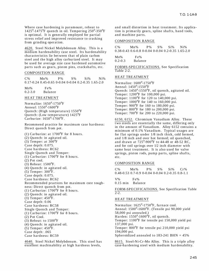
T.O. 1-1A-9
Where case hardening is paramount, reheat to and small distortion in heat treatment. Its applica-1425o-1475oF quench in oil. Tempering 250o-350oF tion is primarily gears, spline shafts, hand tools,is optional. It is generally employed for partial and machine parts.stress relief and improved resistance to cracking
COMPOSITION RANGEfrom grinding operation.C% Mn% P% S% Si% Ni%4620. Steel Nickel Molybdenum Alloy. This is a0.38-0.43 0.6-0.8 0-0.04 0-0.04 0.2-0.35 1.65-2.0medium hardenability case steel. Its hardenability
characteristics lie between that of plain carbon Mo% Fe%steel and the high alloy carburized steel. It may 0.2-0.3 Balancebe used for average size case hardened automotiveparts such as gears, piston pins, crackshafts, etc. FORMS-SPECIFICATIONS. See Specification
Table 2-2.COMPOSITION RANGEHEAT TREATMENTC% Mn% P% S% Si% Ni%
0.17-0.24 0.45-0.65 0-0.04 0-0.04 0.2-0.35 1.65-2.0 Normalize: 1600o-1750oFAnneal: 1450o-1550oFMo% Fe%Quench: 1450o-1550oF, oil quench, agitated oil.0.2-3.0 BalanceTemper: 1200oF for 100,000 psi.
HEAT TREATMENT Temper: 1100oF for 120 to 140,000 psi.Temper: 1000oF for 140 to 160,000 psi.Normalize: 1650o-1750oF Temper: 900oF for 160 to 180,000 psi.Anneal: 1550o-1600oF Temper: 800oF for 180 to 200,000 psi.Quench: (High temperature) 1550oF Temper: 700oF for 200 to 220,000 psi.Quench: (Low temperature) 1425oF
Carburize: 1650o-1700oF. 6150, 6152. Chromium Vanadium Alloy. Thesetwo steels are essentially the same, differing onlyRecommend practice for maximum case hardness:in the amount of Vanadium. Alloy 6152 contains aDirect quench from pot.minimum of 0.1% Vanadium. Typical usages are
(1) Carburize: at 1700oF for 8 hours. for f lat springs under 1/8 inch thick, cold formed,(2) Quench: in agitated oil. and 1/8 inch and over hot formed; oil quenched,(3) Temper: at 300oF and drawn at 725o-900oF to 44-48 or 48-52 RC,Case depth: 0.075. and for coil springs over l/2 inch diameter withCase hardness: RC62 same heat treatment. It is also used for valveSingle Quench and Temper: springs, piston rods, pump parts, spline shafts,(1) Carburize: 1700oF for 8 hours. etc.(2) Pot cool.
COMPOSITION RANGE(3) Reheat: 1500oF.(4) Quench: in agitated oil. C% Mn% P% S% Si% Cr%(5) Temper: 300oF. 0.48-0.53 0.7-0.9 0-0.04 0-0.04 0.2-0.35 0.8-1.1Case depth: 0.075.Case hardness: RC62 V% Fe%Recommended practices for maximum core tough- 0.15 min Balanceness: Direct quench from pot.
FORM-SPECIFICATIONS. See Specification Table(1) Carburize: 1700oF for 8 hours.2-2.(2) Quench: in agitated oil.
(3) Temper: 450oF. HEAT TREATMENTCase depth: 0.06
Normalize: 1625o-1750oF, furnace cool.Case hardness: RC58Anneal: 1500o-1600oF. (Tensile psi 90,000 yieldSingle Quench and Temper:58,000 psi annealed.)(1) Carburize: 1700oF for 8 hours.Harden: 1550o-1600oF, oil quench.(2) Pot Cool.Temper: 1100oF for tensile psi 150,000 yield psi(3) Reheat: to 1500oF137,000 psi.(4) Quench: in agitated oil.Temper: 800oF for tensile psi 210,000 yield psi(5) Temper: 450oF.194,000 psi.Case depth: .065Spheroidized annealed to 183-241 BHN = 45%Case hardness: RC59
4640. Steel Nickel Molybdenum. This steel has 8615. Steel-Ni-Cr-Mo Alloy. This is a triple alloyexcellent machinability at high hardness levels, case-hardening steel with medium hardenability.
2-45
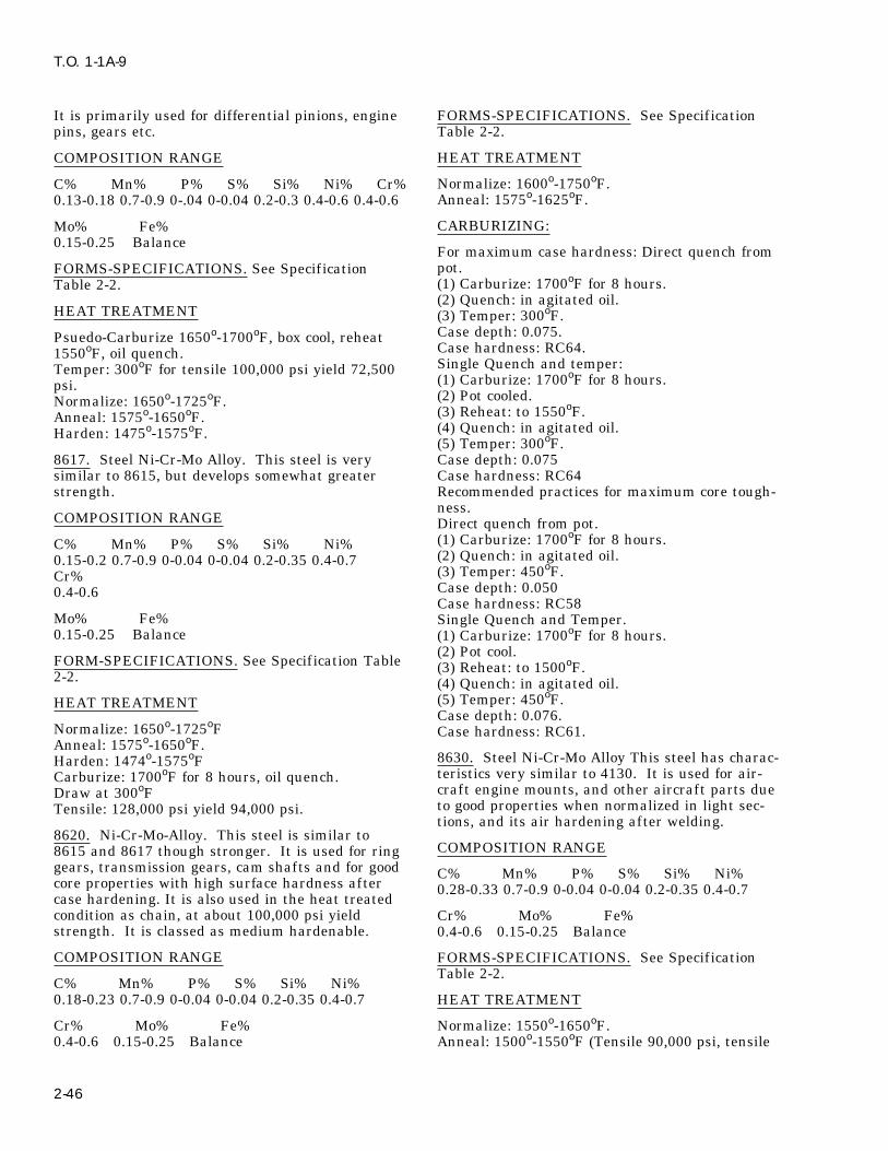
T.O. 1-1A-9
It is primarily used for differential pinions, engine FORMS-SPECIFICATIONS. See Specificationpins, gears etc. Table 2-2.
HEAT TREATMENTCOMPOSITION RANGE
Normalize: 1600o-1750oF.C% Mn% P% S% Si% Ni% Cr%Anneal: 1575o-1625oF.0.13-0.18 0.7-0.9 0-.04 0-0.04 0.2-0.3 0.4-0.6 0.4-0.6
CARBURIZING:Mo% Fe%0.15-0.25 Balance
For maximum case hardness: Direct quench frompot.FORMS-SPECIFICATIONS. See Specification(1) Carburize: 1700oF for 8 hours.Table 2-2.(2) Quench: in agitated oil.
HEAT TREATMENT (3) Temper: 300oF.Case depth: 0.075.Psuedo-Carburize 1650o-1700oF, box cool, reheatCase hardness: RC64.1550oF, oil quench.Single Quench and temper:Temper: 300oF for tensile 100,000 psi yield 72,500(1) Carburize: 1700oF for 8 hours.psi.(2) Pot cooled.Normalize: 1650o-1725oF.(3) Reheat: to 1550oF.Anneal: 1575o-1650oF.(4) Quench: in agitated oil.Harden: 1475o-1575oF.(5) Temper: 300oF.
8617. Steel Ni-Cr-Mo Alloy. This steel is very Case depth: 0.075similar to 8615, but develops somewhat greater Case hardness: RC64strength. Recommended practices for maximum core tough-
ness.COMPOSITION RANGE Direct quench from pot.
(1) Carburize: 1700oF for 8 hours.C% Mn% P% S% Si% Ni%(2) Quench: in agitated oil.0.15-0.2 0.7-0.9 0-0.04 0-0.04 0.2-0.35 0.4-0.7(3) Temper: 450oF.Cr%Case depth: 0.0500.4-0.6Case hardness: RC58
Mo% Fe% Single Quench and Temper.0.15-0.25 Balance (1) Carburize: 1700oF for 8 hours.
(2) Pot cool.FORM-SPECIFICATIONS. See Specification Table (3) Reheat: to 1500oF.2-2. (4) Quench: in agitated oil.
(5) Temper: 450oF.HEAT TREATMENTCase depth: 0.076.
Normalize: 1650o-1725oF Case hardness: RC61.Anneal: 1575o-1650oF.
8630. Steel Ni-Cr-Mo Alloy This steel has charac-Harden: 1474o-1575oFteristics very similar to 4130. It is used for air-Carburize: 1700oF for 8 hours, oil quench.craft engine mounts, and other aircraft parts dueDraw at 300oFto good properties when normalized in light sec-Tensile: 128,000 psi yield 94,000 psi.tions, and its air hardening after welding.
8620. Ni-Cr-Mo-Alloy. This steel is similar toCOMPOSITION RANGE8615 and 8617 though stronger. It is used for ring
gears, transmission gears, cam shafts and for good C% Mn% P% S% Si% Ni%core properties with high surface hardness after 0.28-0.33 0.7-0.9 0-0.04 0-0.04 0.2-0.35 0.4-0.7case hardening. It is also used in the heat treatedcondition as chain, at about 100,000 psi yield Cr% Mo% Fe%strength. It is classed as medium hardenable. 0.4-0.6 0.15-0.25 Balance
COMPOSITION RANGE FORMS-SPECIFICATIONS. See SpecificationTable 2-2.
C% Mn% P% S% Si% Ni%0.18-0.23 0.7-0.9 0-0.04 0-0.04 0.2-0.35 0.4-0.7 HEAT TREATMENT
Cr% Mo% Fe% Normalize: 1550o-1650oF.0.4-0.6 0.15-0.25 Balance Anneal: 1500o-1550oF (Tensile 90,000 psi, tensile
2-46

T.O. 1-1A-9
60,000 annealed), furnace cool. 8740. Steel Ni-Cr-Mo. This steel is similar toHarden: 1500o-1575oF, oil or water quench. 4140. It may be satisfactorily used for axles, toolTemper: 1000oF for 150,000 psi tensile, 140,000 joints, bits, core drills, reamer bodies, drill collars,psi yield strength. piston rods, aircraft engine bolts, shapes, tubingTemper: 700oF for 200,000 psi tensile, 180,000 psi etc.yield strength.
COMPOSITION RANGE8640. Steel Ni-Cr-Mo. Typical uses, propeller C% Mn% P% S% Si% Ni%shafts, transmission gears, spline shafts, heavy 0.38-0.43 0.75-1.0 0-0.04 0-0.04 0.2-0.35 0.4-0.7duty bolts, etc. 4140 has higher strength and duc-tility and slightly better machinability. Cr% Mo% Fe%
0.4-0.6 0.2-0.3 BalanceCOMPOSITION RANGEFORMS-SPECIFICATIONS. See Specification
C% Mn% P% S% Si% Ni% Table 2-2 .0.38-0.43 0.75-1.0 0-0.04 0-0.04 0.2-0.35 0.4-0.7
HEAT TREATMENTCr% Mo% Fe%
Normalize: 1575o-1625oF.0.4-0.6 0.15-0.25 BalanceAnneal: 1500o-1575oF (Tensile 103,000 psi, yield
FORMS-SPECIFICATIONS. See Specification 66,000 psi annealed)Table 2-2. Harden: 1500o-1575oF (Quench in agitated oil)
Temper: 1100oF for tensile 160,000 psi, yieldHEAT TREATMENT152,000 psi.
Normalize: 1550o-1650oF. Temper: 900oF for tensile 190,000 psi, yieldAnneal: 1475o-1575oF. 183,000 psi.Harden: 1475o-1575oF, oil quench. Temper: 800oF for tensile 210,000 psi, yieldTemper: 1100oF for 145,000 psi tensile, 130,000 198,000 psi.psi yield. Temper: 725oF for tensile 220,000.Temper: 800oF for 200,000 psi tensile, 184,000 psi
9260, 9261, 9262. Steel Silicon. These are similaryield.alloy spring steels, oil hardening type. The quan-Temper: 700oF for 220,000 psi tensile, 205,000 psitities of chromium in each, constitutes the onlyyield.chemical variations in these alloys. Typical appli-
8735. Steel Ni-Cr-Mo. This metal is used for cations are coil and f lat springs, axles, chisels,shapes, tubing, aircraft engine studs, knuckles, bolts. etc.etc. It is similar in characteristics to 8630 and
COMPOSITION RANGE8640C% Mn% P% S% Si%FORMS-SPECIFICATIONS. See Specification 9260 0.55-0.65 -0.7-1.0 0-0.04 0-0.04 1.8-2.2Table 2-2.
Cr% Fe%COMPOSITION RANGE --- BalanceC% Mn% P% S% Si% Ni% C% Mn% P% S% Si%0.33-0.38 0.75-1.0 0-0.04 0-0.04 0.2-0.35 0.4-0.7 9261 0.55-0.65 0.75-1.0 0-0.04 0-0.04 1.8-2.2Cr% Mo% Fe% Cr% Fe%0.4-0.6 0.2-0.3 Balance 0.1-0.25 BalanceHEAT TREATMENT C% Mn% P% S% Si%
9262 0.55-0.65 0.75-1.0 0-0.04 0-0.04 1.8-2.2Normalize: 1575o-1625oFAnneal: 1525o-1525oF. Cr% Fe%Harden: 1525o-1600oF Oil quench. 0.25-0.4 BalanceTemper: 1200oF for tensile 119,000 psi, yield
FORMS-SPECIFICATION. See Specification93,000 psi.Table 2-2.Temper: 1100oF for tensile 131,000 psi, yield
107,000 psi. HEAT TREATMENTTemper: 900oF for tensile 149,000 psi, yield127,000 psi Normalize: 1600o-1650oF.Temper: 800oF for tensile 170,000 psi Anneal: 1525o-1575oFTemper: 775oF for tensile 200,000 psi Harden: 1575o-1625oF quench in agitated oil.
2-47

T.O. 1-1A-9
Temper: 1100oF for tensile 165,000 psi, yield Type 301. Steel Austenitic Stainless. This steelbelongs to the sub-family of 18-8 steels, which vary144,000 psi.only slightly in chromium and nickel and containTemper: 900oF for tensile 214,000 psi, yieldno other metallic alloying element. This alloy may192,000 psi.be strengthened to an exceptional degree by coldTemper: 600oF for tensile 325,000 psi, yieldwork. For best results, cold work should be fol-280,000 psi.lowed by stress relieving at 400o-800oF.
9310. Steel Ni Cr-Mo (Electric Furnace Steel).COMPOSITION RANGEThis is a high hardenability case steel, since it is a
high alloy, both the case and core have high C% Mn% Si% P% Cr% Ni% S%hardenability. This type of steel is used particu- 0.08-0.15 0-2.0 0-1.0 0-0.04 17.0-19.0 6.0-8.0 0-0.03larly for carburized parts having thick sections
Cu% Fe%such as bearing races, heavy duty gears etc.0-0.05 Balance
COMPOSITION RANGE FORM-SPECIFICATION. See Specification Table2-2.C% Mn% P% S% Si% Ni%
0.7-0.13 0.4-0.7 0-0.025 0-0.025 0.2-0.35 2.95-3.55 HEAT TREATMENT
Cr% Mo% Fe% Anneal: 1950o-2050oF,1 hour per inch thickness,1.0-1.45 0.08-0.15 Balance water quench.
Cool to 800oF within 3 minutes maximum.FORMS-SPECIFICATIONS. See Specification To relieve the elastic characteristics and increaseTable 2-2. the compressive yield strength of cold worked con-
ditions, 400o-800oF, 36 to 8 hours maximumHEAT TREATMENT respectively. After forming in order to prevent
stress cracking, full anneal, or alternately 600oF,Normalize: 1625o-1725oF, air cool. 1/2 to 2 hours. This alloy can be hardened only byAnneal: 1475o-1575oF, furnace cool. cold work. Maximum tensile strength, 1/4 hardRecommended practice for maximum case hard- 125,000, 1/2 hard 150,000, full hard 185,000 psi.ness: Full anneal is mandatory when, exposed to corro-Direct quench from pot. sive media, such as hot chlorides, etc. which may(1) Carburize: at 1700oF for 8 hours. lead to stress corrosion cracking.(2) Quench: in agitated oil.(3) Temper: 300oF. Type 302. Steel Austenitic Stainless. This alloy isCase depth: 0.047 inch similar to Type 301 in composition and character-Case hardness: RC62 istics. It is inferior in strength to 301, however,Single Quench and Temper: possesses superior corrosive resistance. It is gen-(1) Carburize: 1700oF for 8 hours. erally used in the annealed conditions(2) Pot cool.
COMPOSITION RANGE(3) Reheat: to 1450oF.(4) Quench: in agitated oil. C% Mn% Si% P% S% Cr%(5) Temper: 300oF. 0.08-0.25 0-2.0 0-1.0 0-0.045 0-0.03 17.0-19.0Case depth: 0.047 inch
Ni% Fe%Case hardness: RC62.8.0-10.0 BalanceTo obtain maximum core toughness: Direct
quench from pot. FORMS-SPECIFICATIONS. See Specification(1) Carburize: 1700oF for 8 hours. Table, 2-2.(2) Quench in agitated oil.
HEAT TREATMENT(3) Temper: 450oF.Case depth: 0.039 inch. The heat treatment and resulting strength is simi-Case hardness: RC54. lar to that recommended for type 301, except thatSingle quench and temper: the temperature range for annealing type 302(1) Carburize: 1700oF for 8 hours. ranges between 1925o-2075oF.(2) Pot cool.(3) Reheat to 1450oF. Type 303, Type 303Se, Steel Austenitic Stainless.(4) Quench: in agitated oil. These varieties of the 18-8 austenitic stainless(5) Temper: 450oF. family contain additions of sulphur and seleniumCase depth: 0.047 inch. for the purpose of improving machining character-Case hardness: RC59. istics. However the presence of these elements
2-48
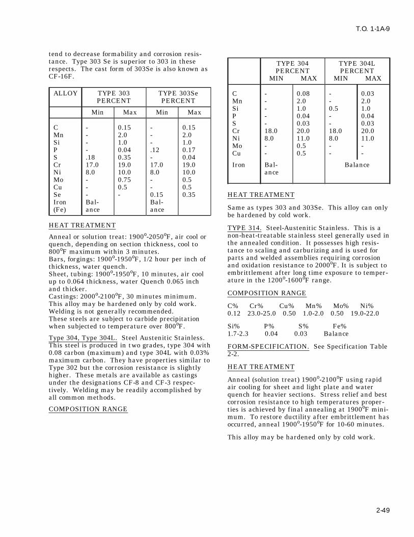
T.O. 1-1A-9
tend to decrease formability and corrosion resis-tance. Type 303 Se is superior to 303 in these TYPE 304 TYPE 304Lrespects. The cast form of 303Se is also known as PERCENT PERCENTCF-16F. MIN MAX MIN MAX
ALLOY TYPE 303 TYPE 303Se C - 0.08 - 0.03PERCENT PERCENT Mn - 2.0 - 2.0
Si - 1.0 0.5 1.0Min Max Min Max P - 0.04 - 0.04S - 0.03 - 0.03C - 0.15 - 0.15 Cr 18.0 20.0 18.0 20.0Mn - 2.0 - 2.0 Ni 8.0 11.0 8.0 11.0Si - 1.0 - 1.0 Mo - 0.5 - -P - 0.04 .12 0.17 Cu - 0.5 - -S .18 0.35 - 0.04
Cr 17.0 19.0 17.0 19.0 Iron Bal- BalanceNi 8.0 10.0 8.0 10.0 anceMo - 0.75 - 0.5Cu - 0.5 - 0.5Se - - 0.15 0.35 HEAT TREATMENTIron Bal- Bal-
Same as types 303 and 303Se. This alloy can only(Fe) ance ancebe hardened by cold work.
HEAT TREATMENT TYPE 314. Steel-Austenitic Stainless. This is anon-heat-treatable stainless steel generally used inAnneal or solution treat: 1900o-2050oF, air cool orthe annealed condition. It possesses high resis-quench, depending on section thickness, cool totance to scaling and carburizing and is used for800oF maximum within 3 minutes.parts and welded assemblies requiring corrosionBars, forgings: 1900o-1950oF, 1/2 hour per inch ofand oxidation resistance to 2000oF. It is subject tothickness, water quench.embrittlement after long time exposure to temper-Sheet, tubing: 1900o-1950oF, 10 minutes, air coolature in the 1200o-1600oF range.up to 0.064 thickness, water Quench 0.065 inch
and thicker. COMPOSITION RANGECastings: 2000o-2100oF, 30 minutes minimum.This alloy may be hardened only by cold work. C% Cr% Cu% Mn% Mo% Ni%Welding is not generally recommended. 0.12 23.0-25.0 0.50 1.0-2.0 0.50 19.0-22.0These steels are subject to carbide precipitation
Si% P% S% Fe%when subjected to temperature over 800oF.1.7-2.3 0.04 0.03 Balance
Type 304, Type 304L. Steel Austenitic Stainless.This steel is produced in two grades, type 304 with FORM-SPECIFICATION. See Specification Table0.08 carbon (maximum) and type 304L with 0.03% 2-2.maximum carbon. They have properties similar to
HEAT TREATMENTType 302 but the corrosion resistance is slightlyhigher. These metals are available as castings
Anneal (solution treat) 1900o-2100oF using rapidunder the designations CF-8 and CF-3 respec-air cooling for sheet and light plate and watertively. Welding may be readily accomplished byquench for heavier sections. Stress relief and bestall common methods.corrosion resistance to high temperatures proper-
COMPOSITION RANGE ties is achieved by final annealing at 1900oF mini-mum. To restore ductility after embrittlement hasoccurred, anneal 1900o-1950oF for 10-60 minutes.
This alloy may be hardened only by cold work.
2-49

T.O. 1-1A-9
TYPE 314
FORMS BAR PLATE SHEET WIRE
HARDCONDITION ANNEALED ANNEALED ANNEALED ANNEALED DRAWN
THICKNESS-IN 1 IN DIA 0.002 to 0.010 0.002 to 0.010
Tensile 100,000 100,000 100,000 95,000-130,000 245,000-275,000
Yield 50,000 50,000 50,000 35,000-70,000 230,000-260,000
Hardness RB 89 89 89 ------------- -------------
TYPE 316 and 317. Steel Austenitic Stainless. forms a carbide of low solid solubility, the possibil-Wrought products are readily formable and welda- ity of intergranular precipitation and of the associ-ble. Castings are also weldable, and the metal arc ated intergranular corrosion is reduced. There-method is most often used. These alloys have bet- fore, type 321 is used primarily either for partster corrosion resistance than 30302 or 30304 types. fabricated by welding without postweld annealing
or for service at 800o-1500oF. This steel is avail-COMPOSITION RANGE able in all wrought forms. Welding rods and cast-ings are not produced in this type.C% Mn% Si% P% S% Cr%
0-.08 1.25-2.0 0-1.0 0-0.04 0-0.03 16.0-19.0CORROSION RANGENi% Mo% Cu% Iron%
11.0-14.0 2.0-2.5 0-0.5 BalanceC% Mn% Si% P% S% Cr%
FORMS-SPECIFICATIONS. See Specification 0-0.08 0-2.0 0.4-1.0 0-0.04 0-0.03 17.0-20.0Table 2-2.
Ni% Mo% Ti% Cu% Iron (Fe)%HEAT TREATMENT8.0-13.0 0-0.5 *6XC-0.7 0-0.5 Balance
Anneal wrought products 1850o-2150oF, air cool orquench depending on section size. FORMS-SPECIFICATIONS. See SpecificationFor sheet alloys, annealing temperature 1950oF, Table 2-2.minimum.Castings 1950o-2100oF, water or oil quench or air * 6 times columbian content.cool. Low side of temperature range is used forCF 8M, (Cast Alloy) but CF 12M castings should HEAT TREATMENTbe quenched from above 2000oF.Stabilize for high temperature service 1625o- Full anneal 1750o-1850oF, 1 hour per inch in1675oF, stress relieve 400o-500oF, 1/2 to 2 hours. thickness, two hours minimum for plate furnaceThis alloy may be hardened only by cold work. In cool or air cool. Stabilizing anneal for serviceannealed condition, tensile 90,000 psi, yield 45,000 900o-1500oF, heat to 1500o-1650oF one hour perpsi. inch thickness, 2 hours minimum for plate. Stress
relieve after fabrication 1300oF.TYPE 321. Steel Austenitic Stainless.This is oneof the two stabilized 18-8 steels Since titanium This may be hardened only by cold work.
2-50

T.O. 1-1A-9
TYPE 321
TENSILE - YIELDFORM SHEET, STRIP PLATE BAR WIRE
SOFT TEMPERCONDITION ANNEAL ANN+CDTHICKNESS IN -- -- ALL 1 INCH 0.062 0.50
Tensile 90000 85000 85000 95000 115000 95000
Yield 35000 30000 35000 60000 85000 65000
Full anneal or stabilizing anneal will eliminate Welding. Fusions welding of this alloy is compara-sensitized conditions. ble to type 304L. Heavy sections may crack dur-
ing welding or subsequent heating. PostweldTYPES 347 and 348. Steel Austenitic Stainless is annealing is not required, although a stress reliefthe second of two stabilized 18-8 steels (see type is recommended. This steel is subject to carbide321 for other). Since columbian forms a carbide of precipitation at temperatures in excess of 2150oF.very low solubility, the possibility of intergranular
Type 414. Steel Martensitic Stainless. This steelprecipitation and of the associated intergranularhas good resistance to weather and water. Itcorrosion are practically eliminated. Therefore,should be passivated. Stainless type 416 has simi-Type 347 is used principally for parts fabricated bylar mechanical properties, workability and resis-welding without postweld annealing, or for longtance to corrosion, however, corrosion resistance isservice between 800o-1500oF. Columbian is usu-not as good as the 300 series stainless. It hasally associated with the similar element tantalumbetter machinability but less weldability. Typewhich is included in the columbian analysis, speci-420 has higher mechanical properties, similarfying only the total of both elements. Corrosionworkability and machinability.resistance of this alloy is similar to Type 302, how-
ever it has a greater tendency to pitting corrosionCOMPOSITION RANGEand attacks in streaks. Intergranular corrosion is
absent in this steel unless it is overheated to C% Mn% P% S% Si% Cr%above 2150oF. At this temperature columbian car- 0.08-0.15 0-1.0 0-0.04 0-0.03 0-0.10 11.5-13.5bides are going in to solid solution and subsequent
Ni% Fe%rapid cooling, followed by heating to 1200oF, will1.25-2.5 Balancecause precipitation and reduce the resistance to
intergranular attack. A stabilizing anneal will FORMS-SPECIFICATIONS. See Specificationrestore the corrosion resistance. Table 2-2.COMPOSITION RANGE HEAT TREATMENTC% Mn% Si% P% S% Cr% Annealing: 1200o-1300oF.0-0.08 0-2.0 0.5-1.0 0-0.04 0-0.03 17.0-19.0 Hardening: 1800o-1900oF, cool rapidly.
Tensile strength in annealed condition 117,000Ni% Mo% Cb1% Iron (Fe%)yield, 98,000 psi.9.0-13.0 0-0.5 *10XC-1.1 BalanceTensile strength in annealed cold drawn 130,000
*10 Times Columbian Content. yield, 115,000 psi.
FORMS-SPECIFICATIONS. See Specification TYPES 403, 410, 416. Steel-Martensitic Stainless.Table 2-2. This is a free machining type of alloy. Best per-
formance is obtained if heat treated or cold workedHEAT TREATMENT to 180-240 BHN. It is magnetic in the hardenedcondition and is not normally used in the annealedFull anneal wrought products 1800o-1900oF, 1condition.hour per inch of thickness 2 hours minimum for
plate, furnace cool or air cool. Full anneal castings COMPOSITION RANGE1900o-2000oF 30 minutes minimum. Stabilizinganneal for service 800o-1500oF, 1500o-1650oF, 1 C% Mn% P% S% Si% Cr% Mo% Si%hour per inch thickness, 2 hours minimum for 0.15 1.25 0.06 0.15 1.0 14.0 0.6 0.6plate. Stress relieve after fabrication 1300oF.
Fe%Alloy may be hardened only by cold work. Balance
2-51

T.O. 1-1A-9
FORMS-SPECIFICATION. See Specification COMPOSITION RANGETable 2-2. C% Mn% Si% P% S% Cr%HEAT TREATMENT 0.2 1.0 1.0 0.04 0.03 15.0-17.0
Ni%Anneal: 1500o-1650oF, furnace cool 50oF per hour 1.25-2.5to 1100oF.Harden: 1700o-1850oF, cool rapidly, oil and Fe%quench. Balance
Tensile - Yield strength is as follows: FORMS-SPECIFICATIONS. See SpecificationTable 2-2.(1) Annealed - Tensile 75,000 psi, yield 40,000 psi.
(2) Heat Treated - Tensile 110,000 psi, yield HEAT TREATMENT85,000 psi. Type 431 steel must be protected from contamina-(3) Tempered and Drawn - Tensile 100,000 psi, tion at furnace temperature by dry inert atmos-yield 85,000 psi. Weldability is poor except by use phere (organ, helium) or vacuum in the furnaceof low-hydrogen electrodes. working zones, except that air or salt bath fur-Temper: 400o-1300oF. Avoid 700o-1075oF temper naces may be employed for tempering operations.range. Parts shall be transferred from furnace workingTemper: 1300oF for 100,000 psi. zones to the oil bath within a 30-second intervalTemper: 1075oF for 120,000 psi. prior to quenching. Materials in the solution-Temper: 575o-600oF for 180,000 psi. treated condition (not more than 2 percent segre-
gated ferrite or austenite in the microstructure)TYPE 420. Steel Martensitic Stainless. This is a may be hardened by the following treat treatment.medium carbon grade of martensitic stainlesswhich in the past has been intensively used in the HT-200 CONDITIONcutlery industry. It has recently proved satisfac- Austenitize at 1850o±25oF for 30 minutes, quicklytory for air weapon application where its high transfer from furnace to oil quenching bath at notstrength permits heat treatment for tensile over 100oF followed by refrigeration at -strength up to 240,000 psi. In the fully annealed 100oF±10oF for 2 hours, tempering at 550oF±25oFcondition formability of this alloy almost equals for 2 hours, air cool, and final temper atthe 1/4 hard austenitic stainless steels. Shearing 550o±25oF for 2 hours; or austenitize 1850o±25oFtype operations such as blanking and punching are for 30 minutes, marquench into salt bath at 400oF,not recommended. It machines best in conditions air cool to room temperature, refrigerate at -having approximately 225 BHN. 100o±10oF for 2 hours, temper 550o±25oF for 2COMPOSITION RANGE hours, air cool, temper 550oF for 2 hours.
C% Mn% Si% P% S% Cr% HT-125 (125,000 tensile)0.3-0.4 0-1.0 0-1.0 0-0.04 0-0.03 12.0-14.0 Austenitize at 1850o±25oF for 30 minutes, quicklyNi% Mo% Fe% transfer from furnace to oil quench to bath at not0-0.5 0-0.5 Balance over 100oF, temper 1200o±25oF for 2 hours, air
cool, temper 1200o±25oF for 2 hours.FORMS-SPECIFICATIONS. See SpecificationTable 2-2.
CAUTIONHEAT TREATMENT
Full anneal 1550o-1650oF one hour per inch of Avoid tempering or holding withinthickness, furnace cool (50oF per hour) to 1100oF. range from 700o to 1100oF.Subcritical anneal 1300o-1350oF, 3 hours mini-
HT-115 (115,000 Tensile and Yield 90,000 PSI)mum, air cool. Austenitize 1800o-1850oF oilquench, depending on section size. Heavy sections Heat Cond A material to 1800o-1900oF for 30 min-should be preheated at 1250oF. Temper 400o- utes, oil quench from furnace, temper at a temper-1500oF, 3 hours minimum. Tempering between ature not lower than 1100oF.600o-1000oF is not generally recommended due to
HT-175 (175,000 Tensile and 135,000 Yield PSI)reduced ductility and corrosion resistance.Heat Cond A material to 1850o-1950oF, quench inTYPE 431. Steel Martensitic Stainless. This alloyoil from furnace temper at a temperature notis suitable for highly stressed parts in corrosivehigher than 700oF.environment.
2-52 Change 1
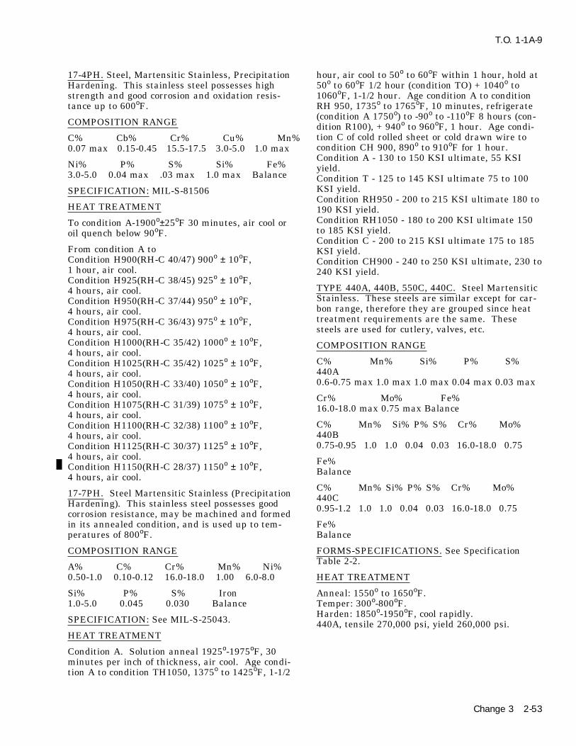
T.O. 1-1A-9
17-4PH. Steel, Martensitic Stainless, Precipitation hour, air cool to 50o to 60oF within 1 hour, hold atHardening. This stainless steel possesses high 50o to 60oF 1/2 hour (condition TO) + 1040o tostrength and good corrosion and oxidation resis- 1060oF, 1-1/2 hour. Age condition A to conditiontance up to 600oF. RH 950, 1735o to 1765oF, 10 minutes, refrigerate
(condition A 1750o) to -90o to -110oF 8 hours (con-COMPOSITION RANGE dition R100), + 940o to 960oF, 1 hour. Age condi-tion C of cold rolled sheet or cold drawn wire toC% Cb% Cr% Cu% Mn%condition CH 900, 890o to 910oF for 1 hour.0.07 max 0.15-0.45 15.5-17.5 3.0-5.0 1.0 maxCondition A - 130 to 150 KSI ultimate, 55 KSI
Ni% P% S% Si% Fe% yield.3.0-5.0 0.04 max .03 max 1.0 max Balance Condition T - 125 to 145 KSI ultimate 75 to 100
KSI yield.SPECIFICATION: MIL-S-81506Condition RH950 - 200 to 215 KSI ultimate 180 to
HEAT TREATMENT 190 KSI yield.Condition RH1050 - 180 to 200 KSI ultimate 150To condition A-1900o±25oF 30 minutes, air cool orto 185 KSI yield.oil quench below 90oF.Condition C - 200 to 215 KSI ultimate 175 to 185
From condition A to KSI yield.Condition H900(RH-C 40/47) 900o ± 10oF, Condition CH900 - 240 to 250 KSI ultimate, 230 to1 hour, air cool. 240 KSI yield.Condition H925(RH-C 38/45) 925o ± 10oF,
TYPE 440A, 440B, 550C, 440C. Steel Martensitic4 hours, air cool.Stainless. These steels are similar except for car-Condition H950(RH-C 37/44) 950o ± 10oF,bon range, therefore they are grouped since heat4 hours, air cool.treatment requirements are the same. TheseCondition H975(RH-C 36/43) 975o ± 10oF,steels are used for cutlery, valves, etc.4 hours, air cool.
Condition H1000(RH-C 35/42) 1000o ± 10oF, COMPOSITION RANGE4 hours, air cool.
C% Mn% Si% P% S%Condition H1025(RH-C 35/42) 1025o ± 10oF,440A4 hours, air cool.0.6-0.75 max 1.0 max 1.0 max 0.04 max 0.03 maxCondition H1050(RH-C 33/40) 1050o ± 10oF,
4 hours, air cool. Cr% Mo% Fe%Condition H1075(RH-C 31/39) 1075o ± 10oF, 16.0-18.0 max 0.75 max Balance4 hours, air cool.
C% Mn% Si% P% S% Cr% Mo%Condition H1100(RH-C 32/38) 1100o ± 10oF,440B4 hours, air cool.0.75-0.95 1.0 1.0 0.04 0.03 16.0-18.0 0.75Condition H1125(RH-C 30/37) 1125o ± 10oF,
4 hours, air cool. Fe%Condition H1150(RH-C 28/37) 1150o ± 10oF, Balance4 hours, air cool.C% Mn% Si% P% S% Cr% Mo%17-7PH. Steel Martensitic Stainless (Precipitation 440CHardening). This stainless steel possesses good 0.95-1.2 1.0 1.0 0.04 0.03 16.0-18.0 0.75corrosion resistance, may be machined and formed
in its annealed condition, and is used up to tem- Fe%peratures of 800oF. Balance
COMPOSITION RANGE FORMS-SPECIFICATIONS. See SpecificationTable 2-2.A% C% Cr% Mn% Ni%
0.50-1.0 0.10-0.12 16.0-18.0 1.00 6.0-8.0 HEAT TREATMENT
Si% P% S% Iron Anneal: 1550o to 1650oF.1.0-5.0 0.045 0.030 Balance Temper: 300o-800oF.
Harden: 1850o-1950oF, cool rapidly.SPECIFICATION: See MIL-S-25043. 440A, tensile 270,000 psi, yield 260,000 psi.HEAT TREATMENT
Condition A. Solution anneal 1925o-1975oF, 30minutes per inch of thickness, air cool. Age condi-tion A to condition TH1050, 1375o to 1425oF, 1-1/2
Change 3 2-53

T.O. 1-1A-9
440B, tensile 280,000 psi, yield 270,000 psi. Condition CH900 - 265 KSI ultimate, 260 yield,440C, tensile 285,000 psi, yield 275,000 psi. hardness RC50.
Welding is not recommended. PH 14-8 MO. This alloy (sheet) is similar to PH15-7 MO except it has slightly lower tensile and
15-7-MO. Steel Martensitic Stainless. This alloy yield strength but considerable higher toughnessis a further development of 17-7PH alloy and due and superior welding characteristics. In generalto molybdenum content it can be heat treated to this alloy is unstable during exposure to tempera-high strength at room and elevated temperature tures exceeding 500oF, which is a common charac-(up to 1000oF). The heat treatment is identical to teristic of precipitation hardening stainless steels.17-7PH and other properties are identical or simi-lar to 17-7PH. FORMS AND CONDITIONS - available - sheet
and strip.FORMS - sheet, strip, plate, bars and forgings.
Condition A - annealed C cold worker.SPECIFICATION - AMS 5520, AMS 5657.CHEMICAL CONDITIONCOMPOSITION RANGEC% Mn% Si% Ph% S% Cr%C% Mn% Si% P% S% Cr% 0.02-0-05 1.0 1.0 0.015 1.0 13.50-15.500.09 1.0 1.0 0.4 0.03 14.0-16.0 Ni%Ni% 7.50-9.506.50-7.75Me% Al% Fe%Mo% A1% Fe%2.0-3.0 0.75-1.50 Rem2.0-3.0 0.75-1.50 BalanceHEAT TREATMENTHEAT TREATMENTAnneal to Condition A, 1800o-1850oF, 30 minutesCondition A. Solution anneal sheet and strip,air cool. Age condition A to SRH conditions, 1685o
1925o-1975oF, 3 minutes per 0.1 inch thickness, air1715oF, 1 hour, air cool and within 1 hour cool to -cool. Bar and forgings solution anneal 1925o-100oF, 8 hours + age 1 hour, air cool. Aging at1975oF, 30 minutes per inch thickness, water940o-960oF or 1040o-1060oF is generally used withquench. Age condition A to condition TH1050,the higher temperature giving somewhat lower1375o to 1425oF, 1-1/2 hour (austenite condition-strength but after better toughness. Age colding), air cool to 50o - 60oF within 1 hour, hold atworked alloy, condition C, 890o-910oF or 1040o-50o - 60oF, 1/2 hour (condition T) + 1040o - 1060oF,1060oF, 1 hour, air cool.1-1/2 hour, air cool. Age condition A to condition
RH 950, 1735o - 1765oF, 10 minutes (austenite MECHANICAL PROPERTIES TYPICALconditioning), air cool (condition A 1750) ±90o to
Condition A - 150 KSI ultimate, 65 KSI yield,110oF, 8 hours (condition R100) + 940o to 960oF, 1hardness, RB100 max.hour, air cool. Age condition C, sheet cold rolledCondition SRH 950 - 220 KSI ultimate, 190 KSIor wire cold drawn to condition CH 900, by heat-yield hardness RC40.ing 890o -910oF for 1 hour, air cool. TH and RH
conditions are also used with difference final ageCondition SRH1050 - 200 KSI ultimate, 180 KSIhardening temperatures, such as TH1150,yield, hardness RC38.RH1050, etc.This alloy is subject to salt stress corrosion, how-TYPICAL PROPERTIES FOR VARIOUSever, early test indicate it is superior in thisCONDITIONS:respect to 17-7PH and PH 15-7 MO.
Condition A - 130 to 150 KSI ultimate, 55-65 KSIThis general welding characteristics is similar toyield, hardness 90-100.17-7 PH. Higher toughness may be obtained byCondition T - 125 to 145 KSI ultimate, 75-90 KSIannealing after welding and then heat treating.yield, hardness 28-30.
Condition TH1050 - 190 to 210 KSI ultimate, 170- 19-9 DL 19-9 DX. These stainless steels are not200 KSI yield, hardness RC40-45. heat treatable, but can be hardened to a limitedCondition RH950 - 225 to 240 KSI ultimate, 200- extent by cold working or hot cold working. In225 KSI yield, hardness RC46-48. chemical composition 19-9DL contains columbiumCondition R100 - 180 KSI ultimate, 125 KSI yield, which was replaced by a higher molybdenum andhardness RC40. titanium conten in 19-9DX.Condition C - 220 KSI ultimate, 190 yield, hard-ness RC45. CHEMICAL COMPOSITION OF 19-9DL:
2-54

T.O. 1-1A-9
C% Mn% Si% Ph% Si% Cr% condition SCT 850o, 825o - 875oF. Age to condition0.28-0.35 0.75-1.50 0.30-0.80 0.040 0.030 18.0-21.0 SCT 1000 975o to 1025oF. Double age either con-
dition H or condition-L to condition DA, 1350o -Ni% Mo% W% Cb+Ta Ti% Cu% 1400oF, 2 hours, air cool to 80oF and heat to 825o -8.0-11.0 1.0-1.75 1.0-1.75 0.10-0.35 0.10-0.35 0.50 875oF, 3 hours. Thoroughly degreased and cleanedprior to annealing to avoid harmful surface reac-Fe%tions and to facilitate subsequent pickling. Allow-Balanceance must also be made for growth which will
CHEMICAL COMPOSITION 19-9DX: result from heat treating. The expansion on agingfrom condition H to set amounts to 0.002 - 0.004C% Mn% Si% Ph% S% Cr%inch per inch.0.28-0.35 0.75-1.50 0.30-0.80 0.040 0.030 18.0-21.0
AM-355. Steel - Age Hardening stainless ThisNi% Mo% W% Ti% Cu% Fe%alloy combines high strength at temperatures up8.0-11.0 1.25-2.00 1.0-1.75 0.40-0.75 0.50 Balanceto 850oF with the corrosive resistance of stainless
HEAT TREATMENT steel. This alloy differs from AM-350 by a lowerchromium and a higher carbon content. It pos-Bar and forgings, 1800o to 2150oF (1/2 to 1 hour)sesses good formability in the high temperaturerapid air cool, oil water quench. Sheet/strip, 1650o
annealed condition. Corrosion resistance of thisto 1800oF (1/2 to 1 hour) rapid air cool. Avoidalloy is slightly lower than that of AM-350.higher temperatures to prevent resolution and pre-
cipitation of carbides. FORM-SPECIFICATIONS. See Specification TableCastings, 1950o to 2050o, 1/2 to 1 hour minimum, 2-2.air cool.
HEAT TREATMENTSolution Treat: Same as anneal.Stress relief: 1175o to 1225oF (4 hours) air cool. Anneal to condition H for maximum formabilityThis treatment is applied to hot worked or hot cold and stability.worked material for service up to 1300oF. It is Anneal to condition H: Plate and forgings atalso applied to cold worked materials immediately 1925o-1975oF, 1 hour minimum per inch, waterafter working to prevent stress cracking. quench: sheet and welded tubing, 1850o to 1900oF,Age: Bar and forgings, 1200o to 1400oF, casting 3/4 hour minimum per inch, rapid air cool. Bar1575o to 1625oF, 8 hours minimum, air cool. should not be annealed to condition H unless sub-
sequently subjected to forgings. Anneal to Condi-NOTEtion L: 1685o-1735oF ---Sheet and strip, 3/4 hour
Intergranular corrosion may occur in per inch, air cool; plate 3/4 hour inch, oil or watercertain environments unless annealed quench. Condition H plate, if not subsequentlyat 1800oF, followed by rapid cooling. severely cold formed, should be equalized before
annealing to condition L and aging to conditionAM-350. Steel - Age Hardening Stainless. ThisSCT. Bar forgings and tubing, 1 hour minimumalloy is one of a series of age hardening steelsper inch thickness, oil or water quench. Equalizewhich combines high strength at temperatures upand age bar for best machineability, 1350o-1400oF,to 800oF and higher with the corrosion resistance3 hours, air cool to 80oF maximum + 1000o toof stainless steels.1050oF, 3 hours. Resulting should be approxi-
COMPOSITION RANGE mately RC38 Subzero cool and age condition L tocondition SCT, cool to -100oF, hold 3 hour mini-C% Mn% Si% P% S% Cr%mum, 850o to 1050oF for 3 hours minimum. Age0.08-0.12 0.5-1.25 0-0.5 0-0.04 0-0.03 16.0-17.0condition SCT 850, 825o to 875oF. Age to condi-
Ni% Mo% N% Fe% tion SCT 1000, 975o to 1025oF. Double age condi-4.0-5.0 2.5-3.25 0.07-0.13 Balance tion L to condition DA, 1300o to 1450oF 1 to 2
hours, air cool to 80oF, 825o to 875oF, 3 hours min-FORM-SPECIFICATION TABLE 2-2. imum. Homogenize sand and shell mold castings,2000oF, 2-4 hours, air cool up to 1 inch thick, oil orHEAT TREATMENTwater quench, section above 1 inch.
Anneal to condition H - 1900o to 1950oF, 3/4 hourminimum per inch of thickness, rapid air cool to HNM. Steel - Age Hardening Stainless. This is a80oF. Anneal to condition L - 1685o to 1735oF, 3/4 precipitation hardening austenitic steel, with highhour minimum, per inch of thickness, rapid air rupture and creep properties in the 1000o-cool to 80oF. Subzero cool and age condition L to 1400oand not prone to overage at these tempera-condition SCT, cool to 100oF, hold 3 hours mini- tures. In the solution annealed condition it has amum + 850o to 1050oF, 3 hours minimum Age to Brinell hardness of 201 maximum. It has a low
2-55
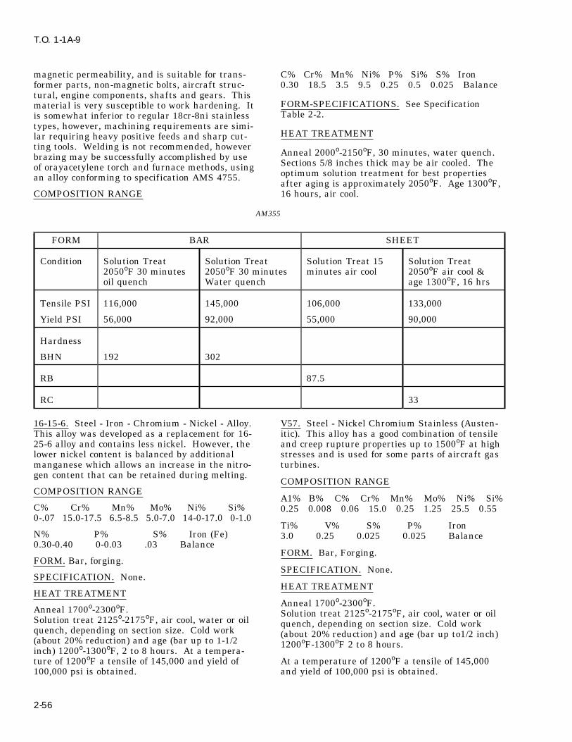
T.O. 1-1A-9
magnetic permeability, and is suitable for trans- C% Cr% Mn% Ni% P% Si% S% Ironformer parts, non-magnetic bolts, aircraft struc- 0.30 18.5 3.5 9.5 0.25 0.5 0.025 Balancetural, engine components, shafts and gears. This
FORM-SPECIFICATIONS. See Specificationmaterial is very susceptible to work hardening. ItTable 2-2.is somewhat inferior to regular 18cr-8ni stainless
types, however, machining requirements are simi-HEAT TREATMENTlar requiring heavy positive feeds and sharp cut-
ting tools. Welding is not recommended, howeverAnneal 2000o-2150oF, 30 minutes, water quench.brazing may be successfully accomplished by useSections 5/8 inches thick may be air cooled. Theof orayacetylene torch and furnace methods, usingoptimum solution treatment for best propertiesan alloy conforming to specification AMS 4755.after aging is approximately 2050oF. Age 1300oF,
COMPOSITION RANGE 16 hours, air cool.
AM355
FORM BAR SHEET
Condition Solution Treat Solution Treat Solution Treat 15 Solution Treat2050oF 30 minutes 2050oF 30 minutes minutes air cool 2050oF air cool &oil quench Water quench age 1300oF, 16 hrs
Tensile PSI 116,000 145,000 106,000 133,000
Yield PSI 56,000 92,000 55,000 90,000
Hardness
BHN 192 302
RB 87.5
RC 33
16-15-6. Steel - Iron - Chromium - Nickel - Alloy. V57. Steel - Nickel Chromium Stainless (Austen-This alloy was developed as a replacement for 16- itic). This alloy has a good combination of tensile25-6 alloy and contains less nickel. However, the and creep rupture properties up to 1500oF at highlower nickel content is balanced by additional stresses and is used for some parts of aircraft gasmanganese which allows an increase in the nitro- turbines.gen content that can be retained during melting.
COMPOSITION RANGECOMPOSITION RANGE
A1% B% C% Cr% Mn% Mo% Ni% Si%C% Cr% Mn% Mo% Ni% Si% 0.25 0.008 0.06 15.0 0.25 1.25 25.5 0.550-.07 15.0-17.5 6.5-8.5 5.0-7.0 14-0-17.0 0-1.0
Ti% V% S% P% IronN% P% S% Iron (Fe) 3.0 0.25 0.025 0.025 Balance0.30-0.40 0-0.03 .03 Balance
FORM. Bar, Forging.FORM. Bar, forging.
SPECIFICATION. None.SPECIFICATION. None.
HEAT TREATMENTHEAT TREATMENT
Anneal 1700o-2300oF.Anneal 1700o-2300oF. Solution treat 2125o-2175oF, air cool, water or oilSolution treat 2125o-2175oF, air cool, water or oil quench, depending on section size. Cold workquench, depending on section size. Cold work (about 20% reduction) and age (bar up to1/2 inch)(about 20% reduction) and age (bar up to 1-1/2 1200oF-1300oF 2 to 8 hours.inch) 1200o-1300oF, 2 to 8 hours. At a tempera-ture of 1200oF a tensile of 145,000 and yield of At a temperature of 1200oF a tensile of 145,000100,000 psi is obtained. and yield of 100,000 psi is obtained.
2-56

T.O. 1-1A-9
SUPPER ALLOYS H/L SPECIFICATION. None.
V36. Steel Cobalt Base - Chromium-Nickel-Alloy. FORMS. Available in ‘‘as cast condition’’.This is a solid solution - hardening alloy for ser-vice at 1300o-1800oF where strength and corrosion HEAT TREATMENTresistance is important. Used for guide vanes ingas turbines, after burner parts and high tempera- Stress relief: 1575o-1625oF, 2 hours, air cool. Ageture springs. Chief ly furnished in sheet, but may hardening: Above 1200oF susceptible to age hard-be supplied in billet, bar, forging and wire. ening which increases alloy strength but causes
loss in ductility.COMPOSITION RANGE Tensile Strength: As cast, tensile strength 125,000
psi. Rockwell As cast, RC38.C% Cr% C1% Ta% Iron% Mn% Mo%0.25-0.33 24.0-26.0 1.5-2.5 0-5.0 0-1.2 3.5-4.5 HAYNES ALLOY NO. 151. Cobalt Base Corrosion
Resistant Alloy. This alloy may be air melted orNi% Si% W% S% P% Cobaltair cast. It is used as gas turbine blades and19.0-21.0 0-1.0 1.5-2.5 0-0.03 0-0.03 Balancerotors within the heat range 1200o-1700oF.
SPECIFICATION. None.COMPOSITION RANGE
HEAT TREATMENTB% C% Cr% Iron% Mn% Ni%This alloy is primarily solid solution hardened and 0.03-0.08 0.4-0.5 19.0-21.0 0-2.0 0-1.0 0-1.0only small strength increases can be obtained by
aging. Solution treatment for thick sections 2200o- Si% Ti% W% P% S% Cobalt%2275oF, 1 hour, water quench. Age 1400oF for 16 0-1.0 0.05-0.5 12.0-13.5 0-0.03 0-0.03 Balancehours. Stress relieve cold worked alloy 900oF, 2hours. SPECIFICATION. None.
TYPE V36 FORMS. Available as castings and investmentcastings.
FORM SHEETHEAT TREATMENTCondition
Sol Treat Sol Treat Sol Treat This material is generally used in the ‘‘as cast’’15 min +20%, +60%, condition. The best creep rupture properties are2250oF+ cool cool in the 1300o-1500oF range. Solution treat 2170o-age rapidly rapidly 2200oF 1 hour minimum, rapid air cool. This treat-
ment reduces tensile properties below 1400oF andTensile 147,000 166,000 279,000lowers creep rupture strength.Yield 83,000 127,000 248,000Aging 1400oF 4 hours air cool after solution treat-RC 25 --- ---ing, results in higher tensile properties than ‘‘ascast’’ material, but creep rupture properties are
W152. Steel. Cobalt Chromium Tungsten Corro- somewhat lower than the ‘‘as cast’’ alloy.sion Resistant Alloy. This is a casting alloy gener-ally used in the ‘‘as-cast’’condition. It is used for Hardenability. As-Cast hardness at room tempera-investment cast parts requiring high stress rup- ture RC33.ture properties at elevated temperatures, hasexcellent castability and foundry characteristics. GMR-235. Nickel Base Corrosive Resistant Alloy.Primary use has been first-stage turbine vanes. GMR-235 and GMR-235D are nickel based alloysAlternate Designations. Haynes Alloy No 152, precipitation hardening, high temperature alloysPWA 653, CF 239. developed for investment cast gas turbine wheels,
buckets and vanes, operating above 1400oF. TheyCOMPOSITION RANGE are similar to Hastelloy R-235 but contain morealuminum. The composition with maximum alumi-C% Cr% C1+TA Iron% Mn% Ni%num and titanium content is designated GMR-0.40-0.5 20.0-22.0 1.5-2.5 1.0-2.0 0-0.5 0-1.0235D.
Si% W% P% S% Cobalt0-0.5 10.0-12.0 0-0.04 0-0.04 Balance COMPOSITION RANGE
2-57

T.O. 1-1A-9
Solution treatment 1950o-2000oF 1/2 hour, waterquench. Material treated at higher solution tem-GMR-235 GMR-235Dperature (2200oF) is subject to strain-age cracking.%Final heat treatment after fabrication of sheet andMIN MAX MIN MAXbar depends upon properties desired. To obtainmaximum long time stress-rupture life, solutionA1 2.5 3.5 3.25 4.0treat at 2175o 2225oF, 15 minutes, water quench.B 0.05 0.1 0.05 0.1Then heat to 2025o-2075oF, hold at temperatureC 0.1 0.2 0.1 0.2for 30 minutes and cool in still air. To obtainCr 14.0 17.0 14.0 17.0maximum room and high temperature tensileCo 0.1 0.2 0 0strength or short time rupture strength, solutionIron 8.0 12.0 3.5 5.0treat at 1950o-2000oF hold at temperature for 30Mn 0 0.25 0 0.1minutes and air cool. Then age at 1385o-1415oFMo 4.5 6.0 4.5 6.0hold at temperature for 16 hours and air cool.Si 0 0.60 0 0.3
Ti 1.5 2.5 2.0 3.0 TYPE HASTELLOY ALLOY R-235 Ni Balance Balance Balance Balance
FORM SHEETSPECIFICATIONS. None.
Condition Sol Treat Sol TreatHEAT TREATMENTThickness-in 1975oF Water 2200oF Water
Solution treatment 2050oF 1 to 3 hours, air cool Quench 0.021 Quench 0.70(GMR 235) Solution treatment 2100oF 2 hours, air
Tensile, Max 150,000 150,000cool (GMR-235D). For heavier sections (of bothpsialloys) temperatures should be increased toYield, Max 95,000 95,0002150oF, 2 to 4 hours, air cool. Aging at 1800oF, 5psi RC-Max 27 25hours from the ‘‘as cast’’ condition improves the
stress rupture life of the alloy. These alloys pre-INCONEL ALLOY 718. Steel Nickel Chromiumcipitation harden rapidly during air cooling andStainless Alloy. This is a relatively new alloy andaging treatments are usually unnecessary.heat treatment and fabrication procedures are still‘‘As-Cast’’ room temperatures hardness for bothunder development. It has good properties up toalloys is RC36 maximum. Tensile 115,000 psi1300oF, slow response to age-hardening and goodyield 90,000 psi.ductility from 1200o-1400oF. It is readily weldedForm This material is available in wrought formin either the annealed or aged condition.only, except that GMR235 is available in cast
form.COMPOSITION RANGE
HASTELLOY ALLOY R-235. Nickel Base Corro-A1% C% Cr% C1%+Ta% Cu% Mn%sion Resistant Alloy. This is a nickel base alumi-0.4-1.0 0-0.1 17.0-21.0 4.5-5.75 0-0.75 0-0.50num-titanium precipitation hardening alloy. It
possesses high strength up to 1800oF with good Mo% Ni% Si% Ti% S% Ironresistance to oxidation and overaging in high tem- 2.0-4.0 50.0-55.0 0-0.5 .3-1.3 0-0.03 Balanceperature service. This alloy is readily fabricated
SPECIFICATION. None.and welded in the solution treated condition.
FORMS. Sheet, Strip, Bar, Investment Castings.COMPOSITION RANGE
HEAT TREATMENTA1% B% C% Cr% Co% Iron%1.75-2.25 0-0.009 0-0.16 14.0-17.0 0-2.5 9.0-11.0
Both single age and double age treatments may beemployed, however, the latter is preferred for high-Mn% Mo% Si% Ti% P% S%est strength up to 1300oF. Solution treat rods,0-0.25 4.5-6.5 0-0.6 2.25-2.75 0-0.01 0-0.03bars and forgings 1800o-1900oF. Somewhat higher
Ni% creep rupture properties are obtained at theBalance higher temperatures. Solution treat sheet at
1725oF. Single age anneal alloy at 1325oF 16SPECIFICATION. None. hours, air cool. Double age anneal alloy at 1325oF
8 hours, furnace cool, 20oF per hour to 1150oF airFORMS. Sheet, Strip, Plate, Bar and Wirecool or 1325oF 8 hours, furnace cool, 100oF per
HEAT TREATMENT hour to 1150oF, hold 8 hours, air cool. Both of
2-58
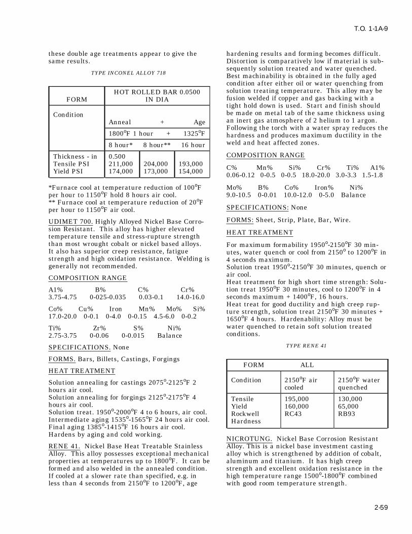
T.O. 1-1A-9
these double age treatments appear to give the hardening results and forming becomes diff icult.same results. Distortion is comparatively low if material is sub-
sequently solution treated and water quenched.TYPE INCONEL ALLOY 718 Best machinability is obtained in the fully aged
condition after either oil or water quenching fromsolution treating temperature. This alloy may beHOT ROLLED BAR 0.0500fusion welded if copper and gas backing with aFORM IN DIAtight hold down is used. Start and finish shouldbe made on metal tab of the same thickness usingConditionan inert gas atmosphere of 2 helium to 1 argon.Anneal + AgeFollowing the torch with a water spray reduces the
1800oF 1 hour + 1325oF hardness and produces maximum ductility in theweld and heat affected zones.8 hour* 8 hour** 16 hourCOMPOSITION RANGEThickness - in 0.500
Tensile PSI 211,000 204,000 193,000 C% Mn% Si% Cr% Ti% A1%Yield PSI 174,000 173,000 154,000 0.06-0.12 0-0.5 0-0.5 18.0-20.0 3.0-3.3 1.5-1.8
*Furnace cool at temperature reduction of 100oF Mo% B% Co% Iron% Ni%per hour to 1150oF hold 8 hours air cool. 9.0-10.5 0-0.01 10.0-12.0 0-5.0 Balance** Furnace cool at temperature reduction of 20oF
SPECIFICATIONS: Noneper hour to 1150oF air cool.FORMS: Sheet, Strip, Plate, Bar, Wire.UDIMET 700. Highly Alloyed Nickel Base Corro-
sion Resistant. This alloy has higher elevated HEAT TREATMENTtemperature tensile and stress-rupture strengththan most wrought cobalt or nickel based alloys. For maximum formability 1950o-2150oF 30 min-It also has superior creep resistance, fatigue utes, water quench or cool from 2150o to 1200oF instrength and high oxidation resistance. Welding is 4 seconds maximum.generally not recommended. Solution treat 1950o-2150oF 30 minutes, quench or
air cool.COMPOSITION RANGE Heat treatment for high short time strength: Solu-tion treat 1950oF 30 minutes, cool to 1200oF in 4A1% B% C% Cr%seconds maximum + 1400oF, 16 hours.3.75-4.75 0-025-0.035 0.03-0.1 14.0-16.0Heat treat for good ductility and high creep rup-
Co% Cu% Iron Mn% Mo% Si% ture strength, solution treat 2150oF 30 minutes +17.0-20.0 0-0.1 0-4.0 0-0.15 4.5-6.0 0-0.2 1650oF 4 hours. Hardenability: Alloy must be
water quenched to retain soft solution treatedTi% Zr% S% Ni%conditions.2.75-3.75 0-0.06 0-0.015 Balance
TYPE RENE 41 SPECIFICATIONS. None
FORMS. Bars, Billets, Castings, ForgingsFORM ALL
HEAT TREATMENTCondition 2150oF air 2150oF waterSolution annealing for castings 2075o-2125oF 2
cooled quenchedhours air cool.Solution annealing for forgings 2125o-2175oF 4 Tensile 195,000 130,000hours air cool. Yield 160,000 65,000Solution treat. 1950o-2000oF 4 to 6 hours, air cool. Rockwell RC43 RB93Intermediate aging 1535o-1565oF 24 hours air cool. HardnessFinal aging 1385o-1415oF 16 hours air cool.Hardens by aging and cold working.
NICROTUNG. Nickel Base Corrosion ResistantRENE 41. Nickel Base Heat Treatable Stainless Alloy. This is a nickel base investment castingAlloy. This alloy possesses exceptional mechanical alloy which is strengthened by addition of cobalt,properties at temperatures up to 1800oF. It can be aluminum and titanium. It has high creepformed and also welded in the annealed condition. strength and excellent oxidation resistance in theIf cooled at a slower rate than specified, e.g. in high temperature range 1500o-1800oF combinedless than 4 seconds from 2150oF to 1200oF, age with good room temperature strength.
2-59

T.O. 1-1A-9
COMPOSITION RANGE e. The structure of the steel to be machined.
A1% B% C% Cr% Co% 2-77. The cutting tool angles (back rake, side3.75-4.75 0.02-0.08 0.08-0.13 11.0-13.0 9.0-11.0 clearance, front clearance, and side rake) are
highly important in the machining of metals. TheTi% W% Zr% Ni% range of values based on general practice for the3.75-4.75 7.0-8.5 0.02-0.08 Balance machining of steel and steel alloys, are as follows:SPECIFICATIONS. None
a. Back rake angle, 8-16 degrees.FORMS. Investment castings.
b. Side rake angle, 12-22 degrees.HEAT TREATMENT
c. Front clearance angle, 8-13 degrees.Heat treatment is not recommended for this alloy.
d. Side clearance angle, 10-15 degrees.This material has ‘‘as-cast’’ hardness of RC38-40.
NIMONIC 105. Nickel-Cobalt-Chromium Corro- 2-78. Regardless of the material of which thesion Resistant Alloy. This alloy has excellent cutting tool is made, the cutting action is theresistance to creep at very high temperatures. It same. The main difference is the cutting speed.is designed for use as turbine blades and rotors The carbon-steel tool cuts at low speed. The high-used in gas turbines. Corrosion resistance is good speed tool cuts at twice the speed of carbon-steel,and resistance to oxidation under repeated heating the cast alloys at twice the speed of high-speedand cooling is very good. steel, and the sintered carbides at twice that of
the cast alloys. The cutting speeds listed in TableCOMPOSITION RANGE 2-4 are approximate speeds using high-speed steeltools, and are to be used only as a basis fromA1% C% Cr% Co% Cu% Iron%which proper speeds for a particular part may be4.2-4.8 0-0.2 13.5-16.0 18.0-22.0 0-0.5 0-1.0calculated. These speeds are based on SAE 1112
Mn% Mo% S1% Ti% Ni% steel, which is assigned a machinability rating of0-1.0 4.5-5.5 0-1.0 0.9-1.5 Balance 100%. In order to obtain an approximate starting
speed for different steels, select the type of opera-SPECIFICATION. Nonetion, the width, depth or diameter of cut and
FORMS. Sheet, Strip, Bar. obtain the recommended cutting speed for SAE1112 from Table 2-3 then refer to Table 2-4 for the
HEAT TREATMENT percent rating of the metal to be machined, andmultiply the SFM value from Table 2-5 by the rat-For maximum stress-rupture life in range 1560o-ing in Table 2-4. The result is the recommended1740oF, fully heat treat solution treat, and doublesurface feet per minute (SFM) for the cutting oper-age as follows: Solution treat 2102oF 4 hours, airation. For a known diameter and surface feet percool. Double age 1922oF, 16 hours, air cool andminute (SFM) be used for an operation, the corre-1526oF, 8 hours, air cool. Where stress rupturesponding revolution per minute (RPM) can bestrength above 1562oF is not the important prop-obtained from Table 2-5.erty, but tensile strength, elongation and impact
strength up to 1292oF is desired, the following 2-79. The term cutting feed is used to expressheat treatment is recommended. the axial distance the tool moves in each revolu-tion. A course feed is usually used for roughingSolution treat 2104oF, 4 hours, air cool.operations, and a fine feed for f inishing opera-Age 1562oF, 16 hours, air cool.tions. In general, the feed remains the same for
2-75. MACHINING OF STEELS (GENERAL). different cutting tool steels, and only the speed ischanged. Approximate cutting feeds are listed in2-76. There are five basic factors affectingTable 2-3. For tool corrections when impropermachinability as related to steel:machining on an operation is encountered, refer to
a. The capacity and rigidity of the machine Table 2-6 for recommended checks.tool.
2-80. The use of a proper coolant (cutting f luid)b. Cutting f luids. often results in an increase of cutting speed for
the same tool life, and also acts as a lubricant giv-c. Design composition and hardness of theing better cutting action and surface finish. Rec-cutting tool.ommended cutting f luids for steels are lard oil,mineral oils, sulphurized oils, and soluble or emul-d. Cutting condition with respect to feeds andsifiable oils.speeds.
2-60

T.O. 1-1A-9
Table 2-3. Cutting Speeds and Feeds for SAE 1112 Using Standard High Speed Tools
TOOL SIZE OF WIDTH OR DEPTH SURFACE FEEDNAME HOLE, IN. OF CUT, IN. FPM IN./REV
Form -- Width - 0.500 165 0.0025Circular Width - 1.000 160 0.0020
or Dovetail Width - 1.500 160 0.0018Width - 2.000 155 0.0015Width - 2.500 150 0.0012
Twist 0.250 105 0.0045Drills 0.500 105 0.005
0.750 115 0.0061.000 115 0.0071.250 120 0.008
Box Depth - 0.125 165 0.007Tools Depth - 0.250 160 0.0065Blade Depth - 0.375 155 0.0055
Depth - 0.500 150 0.0045
Threading Over 25 Pitch 30-40and Tapping 15 to 25 Pitch 20-30
Less than 15 Pitch 15-20
Hollow 0.062 150 0.010Mills 0.125 140 0.008
0.187 135 0.0070.250 130 0.0065
Reamers Under 1/2″ 145 0.007Over 1/2″ 145 0.010
Cut Off Width - 0.062 165 0.002Width - 0.125 175 0.0025Width - 0.187 180 0.0025Width - 0.250 190 0.003
Table 2-4. Machinability Rating of Various Metals
SAEDESIGNATION RATING % BRINELL HARDNESS
1010 50 131-170
1015 50 131-170
1020 65 137-174
1022 70 159-192
1025 65 116-126
1035 65 174-217
1040 60 179-229
1045 60 179-229
1050 50 179-229
1055 55 192-197
1060 60 183-201
2-61
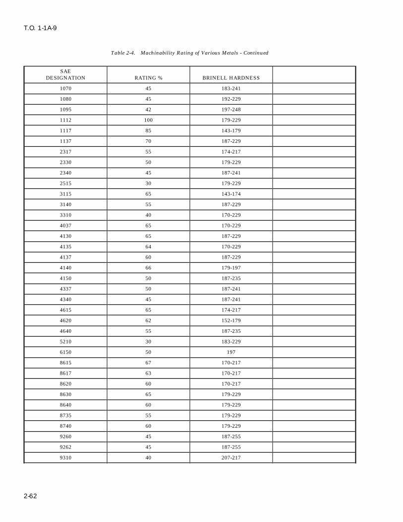
T.O. 1-1A-9
Table 2-4. Machinability Rating of Various Metals - Continued
SAEDESIGNATION RATING % BRINELL HARDNESS
1070 45 183-241
1080 45 192-229
1095 42 197-248
1112 100 179-229
1117 85 143-179
1137 70 187-229
2317 55 174-217
2330 50 179-229
2340 45 187-241
2515 30 179-229
3115 65 143-174
3140 55 187-229
3310 40 170-229
4037 65 170-229
4130 65 187-229
4135 64 170-229
4137 60 187-229
4140 66 179-197
4150 50 187-235
4337 50 187-241
4340 45 187-241
4615 65 174-217
4620 62 152-179
4640 55 187-235
5210 30 183-229
6150 50 197
8615 67 170-217
8617 63 170-217
8620 60 170-217
8630 65 179-229
8640 60 179-229
8735 55 179-229
8740 60 179-229
9260 45 187-255
9262 45 187-255
9310 40 207-217
2-62

T.O. 1-1A-9
Table 2-5. Conversion of Surface Feet Per Minute (SFM) To Revolutions Per Minute (RPM)
DIAMETER SURFACE FEET PER MINUTE
IN INCHES 10 15 20 25 30 40 50 60 70 80 90 100 110
1/16 611 917 1222 1528 1823 2445 3056 3667 4278 4889 5500 6111 6722
1/8 306 458 611 764 917 1222 1528 1833 2139 2445 2750 3056 3361
3/16 204 306 407 509 611 815 1019 1222 1426 1630 1833 2037 2241
1/4 153 229 306 383 458 611 764 917 1070 1222 1375 1528 1681
5/16 122 183 244 306 367 489 611 733 856 978 1100 1222 1345
3/8 102 153 204 255 306 407 509 611 713 815 917 1010 1120
7/16 87 131 175 218 262 349 437 524 611 698 786 873 960
1/2 76 115 153 191 229 306 382 458 535 611 688 764 840
9/16 68 102 136 170 204 272 340 407 475 543 611 679 747
5/8 61 92 122 153 183 244 306 267 428 489 550 611 672
11/16 56 83 111 139 167 222 278 333 389 444 500 556 611
3/4 51 76 102 127 153 203 255 306 357 407 458 509 560
13/16 47 71 94 118 141 188 235 282 329 376 423 470 517
7/8 44 65 87 109 131 175 218 262 306 349 393 436 480
15/16 41 61 81 102 122 163 204 244 285 326 367 407 448
1 38 57 76 96 115 153 191 229 267 306 344 382 420
1 1/8 34 51 68 85 102 136 170 204 238 272 306 340 373
1 1/4 31 46 61 76 92 122 153 183 214 244 275 306 336
1 3/8 28 42 56 69 83 111 139 167 194 222 250 278 306
1 1/2 25 38 51 64 76 102 127 153 178 204 229 255 280
1 5/8 24 35 47 59 70 94 117 141 165 188 212 235 259
1 3/4 22 33 44 55 65 87 109 131 153 175 196 218 240
1 7/8 20 31 41 51 61 81 102 122 143 163 183 204 224
2 19 29 38 48 57 76 95 115 134 153 172 191 210
2 1/4 17 25 34 42 51 68 85 102 119 136 153 170 187
2 1/2 15 23 31 38 46 61 76 92 107 122 137 153 168
2 3/4 14 21 28 35 42 56 69 83 97 111 125 139 153
3 13 19 25 32 38 51 64 76 89 102 115 127 140
DIAMETER SURFACE FEET PER MINUTE
IN INCHES 120 130 140 150 160 170 180 190 200 225 250 270 300
1/16 7334 7945 8556 9167 9778 10390 11000 11612 12223 13751 15279 16807 18334
1/8 3667 3973 4278 4584 4889 5195 5500 5806 6111 6875 7639 8403 9167
3/16 2445 2648 2852 3056 3259 3463 3667 3871 4074 4584 5093 5602 6112
1/4 1833 1986 2139 2292 2445 2597 2750 2903 3056 3438 3820 4202 4584
5/16 1467 1589 1711 1833 1956 2078 2200 2322 2445 2750 3056 3361 3667
3/8 1222 1324 1436 1528 1630 1732 1833 1935 2037 2292 2546 2801 3056
2-63
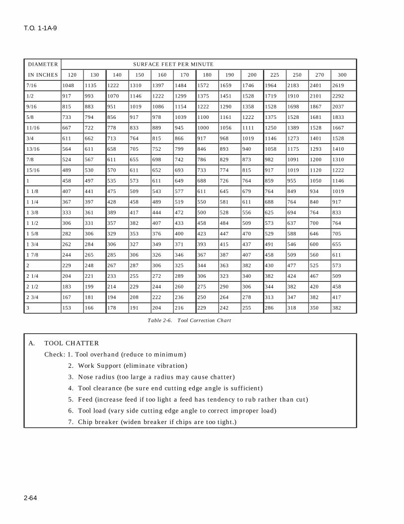
T.O. 1-1A-9
DIAMETER SURFACE FEET PER MINUTE
IN INCHES 120 130 140 150 160 170 180 190 200 225 250 270 300
7/16 1048 1135 1222 1310 1397 1484 1572 1659 1746 1964 2183 2401 2619
1/2 917 993 1070 1146 1222 1299 1375 1451 1528 1719 1910 2101 2292
9/16 815 883 951 1019 1086 1154 1222 1290 1358 1528 1698 1867 2037
5/8 733 794 856 917 978 1039 1100 1161 1222 1375 1528 1681 1833
11/16 667 722 778 833 889 945 1000 1056 1111 1250 1389 1528 1667
3/4 611 662 713 764 815 866 917 968 1019 1146 1273 1401 1528
13/16 564 611 658 705 752 799 846 893 940 1058 1175 1293 1410
7/8 524 567 611 655 698 742 786 829 873 982 1091 1200 1310
15/16 489 530 570 611 652 693 733 774 815 917 1019 1120 1222
1 458 497 535 573 611 649 688 726 764 859 955 1050 1146
1 1/8 407 441 475 509 543 577 611 645 679 764 849 934 1019
1 1/4 367 397 428 458 489 519 550 581 611 688 764 840 917
1 3/8 333 361 389 417 444 472 500 528 556 625 694 764 833
1 1/2 306 331 357 382 407 433 458 484 509 573 637 700 764
1 5/8 282 306 329 353 376 400 423 447 470 529 588 646 705
1 3/4 262 284 306 327 349 371 393 415 437 491 546 600 655
1 7/8 244 265 285 306 326 346 367 387 407 458 509 560 611
2 229 248 267 287 306 325 344 363 382 430 477 525 573
2 1/4 204 221 233 255 272 289 306 323 340 382 424 467 509
2 1/2 183 199 214 229 244 260 275 290 306 344 382 420 458
2 3/4 167 181 194 208 222 236 250 264 278 313 347 382 417
3 153 166 178 191 204 216 229 242 255 286 318 350 382
Table 2-6. Tool Correction Chart
A. TOOL CHATTER
Check: 1. Tool overhand (reduce to minimum)
2. Work Support (eliminate vibration)
3. Nose radius (too large a radius may cause chatter)
4. Tool clearance (be sure end cutting edge angle is sufficient)
5. Feed (increase feed if too light a feed has tendency to rub rather than cut)
6. Tool load (vary side cutting edge angle to correct improper load)
7. Chip breaker (widen breaker if chips are too tight.)
2-64

T.O. 1-1A-9
Table 2-6. Tool Correction Chart - Continued
B. CHIPPING OF CUTTING EDGE
Check: 1. Edge sharpness (Hone or chamber slightly)
2. Chip Breaker (widen breaker if tight chip causes chipping)
3. Speed (Increase)
4. Coolant (Heating and cooling of tip may cause chipping)
C. RAPID TOOL WEAR
Check: 1. Feed (Increase)
2. Speed (Low and excessive speeds cause tool wear)
3. Relief angles (clearance may not be sufficient)
4. Nose radius (decrease size)
D. UNSATISFACTORY FINISH
Check: 1. Speed (rough finishes can be eliminated by increasing speed)
2. Nose radius (too large a nose radius mats finish)
2-81. MACHINING CORROSION RESISTING designated by a suffix to type number such as 430STEEL. F or Se. Exceptions are types 416 and 303.
2-82. The corrosion resisting steels, especially 2-83. For comparison and as a general guide tothe 18-8 grades, are more diff icult to machine the machining characteristics of free machiningthan the carbon steels and most other metals. screw stock grade B1112 as an 100% machinableEven though they are more diff icult to machine, ‘‘norm.’’ This table is only intended as a startingthe same general methods are used with modifica- point and is not intended to replace any informa-tion/compensation for the individual characteris- tion accumulated through experience or othertics of each type or grade. To improve machining available data.characteristics of some types, their chemical con-tent is modified by adding selenium (Se) and sul-fur (S). The modified alloys which are usually
Table 2-7. General Machining Comparison of Corrosion Resisting Steel To Free Machining Screw Stock B1112
MACHINABILITY MACHINABILITYGRADE/TYPE RATING GRADE/TYPE RATING
Group I 430F 80% Group III 420 45%
416 75% 431 45%
420F 70% 440 45%
303 65% 442 45%
446 45%
347 40-45%
Group II 403 55% Group IV 302 40%
410 50% 304 40%
430 50% 309 40%
440F 50% 316 40%
2-65
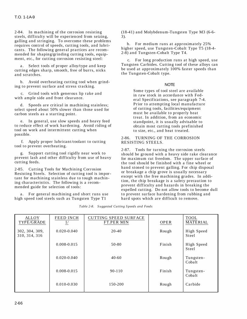
T.O. 1-1A-9
2-84. In machining of the corrosion resisting (18-41) and Molybdenum-Tungsten Type M3 (6-6-steels, diff iculty will be experienced from seizing, 3).galling and stringing. To overcome these problems
b. For medium runs at approximately 25%requires control of speeds, cutting tools, and lubri-higher speed, use Tungsten-Cobalt Type T5 (18-4-cants. The following general practices are recom-2-8) and Tungsten-Cobalt Type T4.mended for shaping/grinding cutting tools, equip-
ment, etc., for cutting corrosion resisting steel: c. For long production runs at high speed, useTungsten Carbides. Cutting tool of these alloys cana. Select tools of proper alloy/type and keepbe used at approximately 100% faster speeds thancutting edges sharp, smooth, free of burrs, nicksthe Tungsten-Cobalt type.and scratches.
b. Avoid overheating cutting tool when grind-NOTEing to prevent surface and stress cracking.
Some types of tool steel are availablec. Grind tools with generous lip rake and in raw stock in accordance with Fed-
with ample side and front clearance. eral Specifications, see paragraph 7-4.Prior to attempting local manufactured. Speeds are critical in machining stainless;of cutting tools, facilities/equipmentselect speed about 50% slower than those used formust be available to properly heatcarbon steels as a starting point.treat. In addition, from an economic
e. In general, use slow speeds and heavy feed standpoint, it is usually advisable toto reduce effect of work hardening. Avoid riding of obtain most cutting tools prefinishedtool on work and intermittent cutting when to size, etc., and heat treated.possible.
2-86. TURNING OF THE CORROSIONf. Apply proper lubricant/coolant to cutting RESISTING STEELS.
tool to prevent overheating.2-87. Tools for turning the corrosion steels
g. Support cutting tool rigidly near work to should be ground with a heavy side rake clearanceprevent lash and other diff iculty from use of heavy for maximum cut freedom. The upper surface ofcutting feeds. the tool should be finished with a fine wheel or
hand stoned to prevent galling. For chip disposal2-85. Cutting Tools for Machining Corrosionor breakage a chip grove is usually necessaryResisting Steels. Selection of cutting tool is impor-except with the free machining grades. In addi-tant for machining stainless due to tough machin-tion, the chip breakage is a safety precaution toing characteristics. The following is a recom-prevent diff iculty and hazards in breaking themended guide for selection of tools:expelled cutting. Do not allow tools to become dull
a. For general machining and short runs use to prevent surface hardening from rubbing andhigh speed tool steels such as Tungsten Type T1 hard spots which are diff icult to remove.
Table 2-8. Suggested Cutting Speeds and Feeds
ALLOY FEED INCH CUTTING SPEED SURFACE TOOLTYPE/GRADE 1/ FT.PER MIN OPER MATERIAL
302, 304, 309, 0.020-0.040 20-40 Rough High Speed310, 314, 316 Steel
0.008-0.015 50-80 Finish High SpeedSteel
0.020-0.040 40-60 Rough Tungsten-Cobalt
0.008-0.015 90-110 Finish Tungsten-Cobalt
0.010-0.030 150-200 Rough Carbide
2-66

T.O. 1-1A-9
Table 2-8. Suggested Cutting Speeds and Feeds - Continued
ALLOY FEED INCH CUTTING SPEED SURFACE TOOLTYPE/GRADE 1/ FT.PER MIN OPER MATERIAL
0.008-0.018 150-300 Finish Carbide
420, 431, 440, 0.015-0.040 20-40 Rough High Speed442, 446, 347, Steel321
0.008-0.018 55-90 Finish High SpeedSteel
0.015-0.040 40-80 Rough Tungsten-Cobalt
0.008-0.018 100-130 Finish Tungsten-Cobalt
0.015-0.030 165-220 Rough Carbide
0.005-0.015 165-330 Finish Carbide
430F, 416 0.015-0.040 30-60 Rough High SpeedSteel
0.008-0.018 75-120 Finish High SpeedSteel
0.015-0.040 60-105 Rough Tungsten-Cobalt
0.005-0.015 135-180 Finish Tungsten-Cobalt
0.010-0.030 225-300 Rough Carbide
0.005-0.015 225-450 Finish Carbide
420F 0.015-0.050 25-55 Rough High SpeedSteel
303 0.005-0.015 65-105 Finish High SpeedSteel
0.020-0.050 50-90 Rough Tungsten-Cobalt
2-67
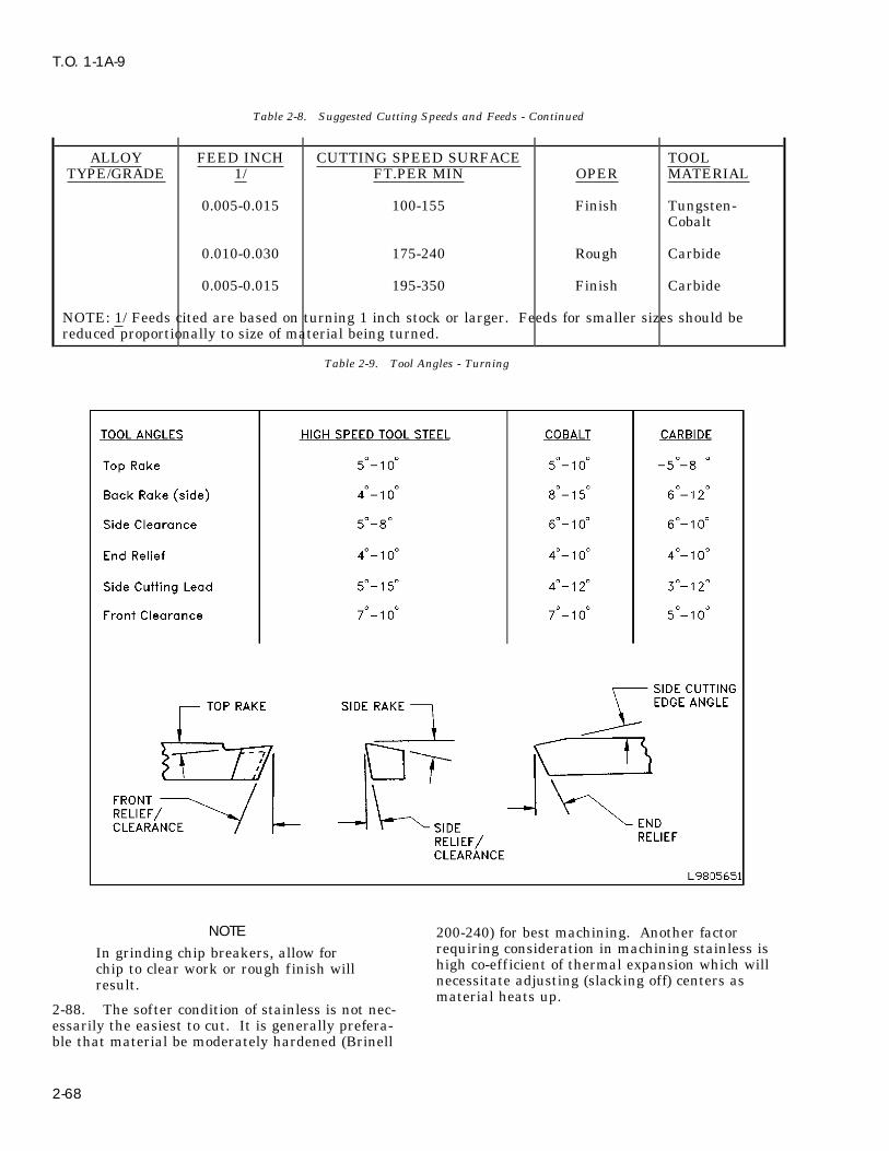
T.O. 1-1A-9
Table 2-8. Suggested Cutting Speeds and Feeds - Continued
ALLOY FEED INCH CUTTING SPEED SURFACE TOOLTYPE/GRADE 1/ FT.PER MIN OPER MATERIAL
0.005-0.015 100-155 Finish Tungsten-Cobalt
0.010-0.030 175-240 Rough Carbide
0.005-0.015 195-350 Finish Carbide
NOTE: 1/ Feeds cited are based on turning 1 inch stock or larger. Feeds for smaller sizes should bereduced proportionally to size of material being turned.
Table 2-9. Tool Angles - Turning
NOTE 200-240) for best machining. Another factorrequiring consideration in machining stainless isIn grinding chip breakers, allow forhigh co-efficient of thermal expansion which willchip to clear work or rough finish willnecessitate adjusting (slacking off) centers asresult.material heats up.
2-88. The softer condition of stainless is not nec-essarily the easiest to cut. It is generally prefera-ble that material be moderately hardened (Brinell
2-68
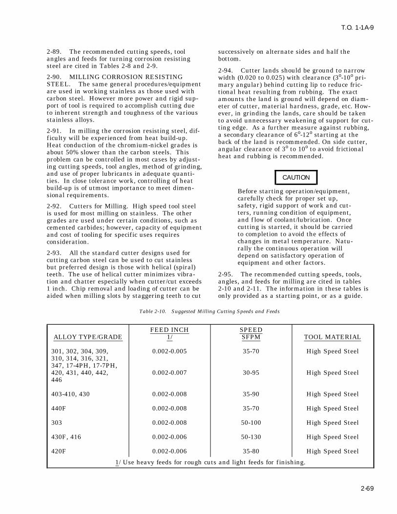
T.O. 1-1A-9
2-89. The recommended cutting speeds, tool successively on alternate sides and half theangles and feeds for turning corrosion resisting bottom.steel are cited in Tables 2-8 and 2-9.
2-94. Cutter lands should be ground to narrow2-90. MILLING CORROSION RESISTING width (0.020 to 0.025) with clearance (3o-10o pri-STEEL. The same general procedures/equipment mary angular) behind cutting lip to reduce fric-are used in working stainless as those used with tional heat resulting from rubbing. The exactcarbon steel. However more power and rigid sup- amounts the land is ground will depend on diam-port of tool is required to accomplish cutting due eter of cutter, material hardness, grade, etc. How-to inherent strength and toughness of the various ever, in grinding the lands, care should be takenstainless alloys. to avoid unnecessary weakening of support for cut-
ting edge. As a further measure against rubbing,2-91. In milling the corrosion resisting steel, dif- a secondary clearance of 6o-12o starting at theficulty will be experienced from heat build-up. back of the land is recommended. On side cutter,Heat conduction of the chromium-nickel grades is angular clearance of 3o to 10o to avoid frictionalabout 50% slower than the carbon steels. This heat and rubbing is recommended.problem can be controlled in most cases by adjust-ing cutting speeds, tool angles, method of grinding,and use of proper lubricants in adequate quanti-
CAUTIONties. In close tolerance work, controlling of heatbuild-up is of utmost importance to meet dimen- Before starting operation/equipment,sional requirements. carefully check for proper set up,
safety, rigid support of work and cut-2-92. Cutters for Milling. High speed tool steelters, running condition of equipment,is used for most milling on stainless. The otherand f low of coolant/lubrication. Oncegrades are used under certain conditions, such ascutting is started, it should be carriedcemented carbides; however, capacity of equipmentto completion to avoid the effects ofand cost of tooling for specific uses requireschanges in metal temperature. Natu-consideration.rally the continuous operation will
2-93. All the standard cutter designs used for depend on satisfactory operation ofcutting carbon steel can be used to cut stainless equipment and other factors.but preferred design is those with helical (spiral)teeth. The use of helical cutter minimizes vibra- 2-95. The recommended cutting speeds, tools,tion and chatter especially when cutter/cut exceeds angles, and feeds for milling are cited in tables1 inch. Chip removal and loading of cutter can be 2-10 and 2-11. The information in these tables isaided when milling slots by staggering teeth to cut only provided as a starting point, or as a guide.
Table 2-10. Suggested Milling Cutting Speeds and Feeds
FEED INCH SPEEDALLOY TYPE/GRADE 1/ SFPM TOOL MATERIAL
301, 302, 304, 309, 0.002-0.005 35-70 High Speed Steel310, 314, 316, 321,347, 17-4PH, 17-7PH,420, 431, 440, 442, 0.002-0.007 30-95 High Speed Steel446
403-410, 430 0.002-0.008 35-90 High Speed Steel
440F 0.002-0.008 35-70 High Speed Steel
303 0.002-0.008 50-100 High Speed Steel
430F, 416 0.002-0.006 50-130 High Speed Steel
420F 0.002-0.006 35-80 High Speed Steel
1/ Use heavy feeds for rough cuts and light feeds for f inishing.
2-69

T.O. 1-1A-9
Table 2-11. Suggested Tool Angles - Milling
TOOL MATERIALTOOL ANGLES HIGH SPEED STEEL CEMENTED CARBIDE/C ALLOY
Rake Radial 1/ 10o-20o Use lower angle
Rake Axial 1/ 30o-50o Use lower angle
Clearance 4o-8o Approximately same
Land Width 1/64″-1/16″ Approximately same
1/ Saws, form relieved cutters, and miscellaneous profile cutters, etc., are sometimes usedwith rake angle as low as 0 degrees.
2-96. Lubrication for Milling. The lubrication ofTable 2-12. Drilling Speeds for Corrosion Resisting Steel milling cutter is very important to control genera-
tion of heat which is considerable in cutting allgrades of stainless, and to prevent seizing of chips SPEED SFPMto cutting edges. The cutting oils used should be GRADE TYPE (APPROX)applied in large quantities directly on the cutterand zone of cut. The sulphurized oils diluted to 301, 302, 304, 310 20 - 40desired viscosity with paraffin oil are usually 303 40 - 80satisfactory. 309, 316, 321, 347 30 - 50
403, 410 35 - 752-97. DRILLING CORROSION RESISTING416, 420F, 430F 60 - 95STEEL. High speed steel drills are commonly420 AB & C 20 - 40used for drilling stainless. Special types are used442, 446 30 - 60for drilling grades (420, 440, etc.) that are abrasive
due to high carbon content. Speeds for drilling thehigh carbon types are usually reduced 25-50%o in NOTEcomparison to the other grades. Do not let drill ride on work to pre-
vent work hardening and heat dam-2-98. Drills for use with the corrosion resistingage to drill. On larger diameter drillssteels are prepared with different cutting anglesuse chip curling grooves to help expelthan used with carbon steel. Drill point/tips forand prevent chip accumulation inuse with the chromium-nickel grades are usuallyarea of hole being drilled.ground with 135o-140o (included) angle and 8o-15o
lip clearance. The webb support for the point 2-100. Lubrication for Drilling Stainless. Theshould be as heavy as possible; however, thinning recommended lubrication for general use and lightof the webb at the point will relieve point pres- drilling is soluble oil, and for heavy work,sure. When drilling the free machining 400 series sulphurized mineral or fatty oils. Utilization ofgrades the angle is reduced to 118o-130o. For gen- adequate lubrication/ coolant is of utmost impor-eral illustration of point designs see Figure 3-2. tance in drilling stainless due to poor heat conduc-tion of this material.2-99. Speeds used for drilling the corrosion
resisting steels should be closely controlled to pre- 2-101. REAMING CORROSION RESISTINGvent hardening of metal and excessive drill dam- STEEL. The recommended reamer for the corro-age from heat. For suggested drilling speed using sion resisting steels is the spiral f luted type whichhigh speed steel drill bits, see Table 2-12. is made from high speed steel/carbide tipped.These spiral f luted reamers are used to help alle-viate chatter and chip removal that are associatedwith the straight f luted reamers.
2-102. Due to the work hardening characteristicsof the corrosion resisting steel, it is advisable toleave sufficient stock to insure that cutting willoccur behind the work hardening surface resultingfrom drilling. The recommended material to be leftfor reaming is 0.003-0.007 inch, and feed perrevolution should be 0.003-0.005 for holes up to 1/2
2-70

T.O. 1-1A-9
inch and 0.005-0.010 for reamers up to 1 inch taps for small holes. For instance modification ofdiameter. taps can be accomplished by grinding longitudinal
grooves along the lands, omission of cutting edges2-103. Reamers for cutting stainless should have on alternate threads and relieving cutting edgesa 26o-30o starting chamfer with a slight lead angle will reduce binding and frictional drag. Thesebehind the chamfer of 1o-2o for about 1/8-3/16 inch modifications will also aid in distribution of lubri-on the land to reduce initial shock of cutting. The cation to cutting area, provide additional clearanceland should be ground with a clearance of 4o-7ofor chips and compensate for the swelling which is(and width should not be reduced below 0.010- encountered with the softer temper material. The0.012 inch) to reduce rubbing and frictional heat. modification is usually accomplished as follows:
2-104. Speeds for reaming will vary according toa. Longitudinal grooves are ground down thetype of material being cut. The recommended
center of each land about 1/3 to 1/2 thread depthspeed for reaming types 301, 302, 304, 316, 321,and 1/3 to 1/2 approximately of land width.347, 403 and 410 is 20 - 75 surface feet per min-
ute; for 430F, 420F, 416, 440F and 303 --35 - 100b. Cutting edges are relieved by grinding a 2o-SFPM; and for 309, 310, 430, 431, 440, 442, 426 -
5o radial taper on each land.20-60 SFPM. Trial should be conducted to deter-mine best cutting for indivldua1 operations. c. Lands are narrowed by removing about
half the threading area from each land. The por-2-105. TAPPING CORROSION RESISTINGtion removed should trail the foremost cuttingSTEEL. Conventional or standard type taps areedge. Also, cutting edge should be ground to haveused with stainless; however, better results canpositive hook/rake 15o-20o for softer material andsometimes be obtained by modification of taps (in
shop) as required and by use of two f luted type 10o-15o for harder material.
Table 2-13. Tapping Allowances (Hole Size to Screw Size)
THREAD/SCREW DRILL SIZE THREAD DEPTHSIZE MAJOR DIA. MINOR DIA. DECIMAL & NR PERCENT
4-40 0.1120 0.0871±0.002 0.0810-46 95
0.827-45 90
0.0860-44 80
0.0890-43 71
0.0960-41 49
6-32 0.1380 0.1100±0.004 0.0995-39 95
0.1040-37 83
0.1100-35 72
0.1160-32 54
6-40 0.1380 0.1144±0.0035 0.1065-36 97
0.1130-33 77
0.1200-31 65
8-32 0.1640 0.1342±0.004 0.1250-1/8″ 96
0.1285-30 87
0.1360-29 69
0.1405-28 57
2-71

T.O. 1-1A-9
Table 2-13. Tapping Allowances (Hole Size to Screw Size) - Continued
THREAD/SCREW DRILL SIZE THREAD DEPTHSIZE MAJOR DIA. MINOR DIA. DECIMAL & NR PERCENT
10-32 0.1900 0.1593±0.003 0.1520-24 93
0.1562-5/32″ 83
0.1610-20 71
0.1660-19 59
0.1695-18 50
1/4-20 0.2500 0.2010±0.005 0.1850-13 100
0.1875-3/16″ 96
0.1935-10 87
0.1990-8 78
0.2090-4 63
1/4-24 0.2500 0.2143±0.003 0.1960-9 100
2031-13/64″ 86
0.2090-4 75
0.2130-3 68
1/4-28 0.2500 0.2193±0.002 0.2090-4 88
0.2130-3 80
0.2187-7/32″ 67
5/16-24 0.3125 0.2708±0.0032 0.2610-G 95
0.2656-17/64″ 86
0.2720-1 75
0.2770-J 65
3/8-24 0.3750 0.3278±0.002 0.3281-2 1/64″ 86
0.3320-Q 70
0.3390-R 66
1/2-24 0.5000 0.4579±0.003 0.4531-29/64″ 86
0.4687-15/32″ 57
2-106. In addition to the above, the tap basically 2-107. Due to high strength and poorer cuttingshould have a taper/chamfer of about 9o with quality of the stainless series steels, holes for tap-center line on the starting end to facilitate entry ping are usually made as large as possible consis-into hole. The taper should be held short (1st tent with fit specified by drawing or other data.thread) for blind holes, and on through holes, it Actually due to the higher strength of this mate-may extend over 3 or 4 threads rial less thread area or engagement is required in
comparison to most other metals. Due to theabove and the fact that less cutting is required,75% thread depth is generally used as maximum
2-72

T.O. 1-1A-9
unless otherwise specified. Higher percentages of bars, tubing, etc. With the power hack saw,thread depth are necessary in material when stock deeper cuts are made at relatively low speed. Theis not thick enough to permit the required number deeper cuts are used to get under work hardenedof thread. For tapping allowances of some size surface resulting from previous cut (stroke). Thescrews/bolts see Table 2-13. teeth per inch for saw blades average 8-12 and
speed of saw travel usually ranges from 50-1002-108. The decreased thread depth also reduces feet per minute depending on type and temper oftendency to gall and seize, power required to drive material being cut. Coolant/lubrication is essen-tap, tap wear, and effect of swelling in soft tial to prevent excess blade damage from heat.material. Lubrication recommended is soluble oil/watermixed about 1 part oil to 4 parts water for heavy2-109. Tapping Speeds Corrosion Resisting Steel.work, and for light work, a light grade cutting oil.Tapping speeds used for stainless should be slower
than those used for carbon steel. The 18-8 (300 2-114. Band Sawing. Band saws are well suitedseries) are usually tapped at 10-25 SFPM except for low speed (straight line/contour) sawing offor the free machining types which are tapped at stainless/corrosion resisting steel within prescribed15-30 SFPM. The straight-chromium 400 series limitation. The saw manufacturer’s recommenda-generally is tapped at 15-25 SFPM, except the free tions should be followed for cutting speed, sawmachining grades, which are tapped at 15-35 selection, etc. However, speeds usually vary withSFPM. the physical properties, temper, etc., of type/gradebeing cut. As general guide, speeds range from2-110. Lubrication for Tapping. The lubrications100-125 feet per minute for material under 0.062recommended for tapping are sulphurized mineraland 60-100 FPM for thickness over 0.062 inch.oils with paraffin and lard oil. The lubricantSaw blades must be kept in sharp condition forserves to prevent overheating as well as lubrica-effective low speed sawing.tion, and if applied under pressure, aids in chip
removal. Oil f low/application should be applied 2-115. For faster cutting with the band saw, thebefore tapping commences to prevent initial con- friction cutting method may be employed. Ingestion of cuttings. utilizing the friction method, the band saw velocityranges from 5000 FPM for cutting f lat 1/32 inch2-111. SAWING.material to about 10,000 FPM for 1/2 inch and
2-112. Hack saws (hand) for cutting corrosion 14,000 for 1 inch material; tubing material is runresisting steel should be of high speed steel with at slightly higher speed. Feed for this method canapproximately 32 teeth per inch for light work and be considerably higher than is used for slow speedapproximately 24 teeth per inch for heavy work. cutting, rates range from about 100 FPM for lightThe teeth area should be of wavy construction to gauge to 15-18 FPM for 1/2 inch material. Sawincrease width of cut area to prevent binding. As teeth per inch varies from 18 for material belowwith cutting other metal, the blade should not be 1/ 8 inch thick to 10 per inch for thicknesses overallowed to drag/ride on the return stroke, espe- 1/2 inch.cially with the 300 series types to prevent work
2-116. Heavy pressure to maintain cut is nothardening. The hack saw blade should be lightlyusually necessary. Pressure should be just suffi-lubricated with lard oil/other cutting oil for bestcient to create proper heating and softening at cutresults.point without forcing the saw. Lubricants should
2-113. Hack saws (mechanical drive). Power not be used.hack saws are used for heavy cross-cutting section
Paragraph 2-117 through 2-227 deleted.Tables 2-14 through 2-33 deleted.Figures 2-2 and 2-3 deleted.Pages 2-75 through 2-120 deleted.
Change 1 2-73/(2-74 blank)


T.O. 1-1A-9
2-228. (Deleted) reading, assembly, etc., in accordance with scope ofrelation to fabrication process. Also, these person-2-229. (Deleted) nel must keep constantly abreast of advancingprocesses for maximum efficiency/proficiency.2-230. (Deleted)
2-236. The section of steel for design or applica-2-231. (Deleted)tion to equipment and component is usually based
2-232. (Deleted) on the following:2-233. (Deleted) a. Strength and weight requirement of part/
equipment to be fabricated.2-234. FABRICATION OF FERROUS ALLOYS. Theinformation furnished in this section is provided as b. Method to be used for fabrication, i.e.,a guide to aid personnel engaged in the use and welding, forming, machining, heat treat, etc.application of the ferrous alloys. Due to varied
c. Corrosion resistance to certain chemicals/usage of steel products, details and rules relatedenvironments.will not f it every application. In many instances,
experimentation trial and further study will be d. Temperatures to which part will berequired. subjected.2-235. Personnel assigned to accomplish designs, e. Fatigue properties under cyclic loads, etc.application and fabrication must be well trained infundamentals of metal forming practices, analysis, 2-237. The following general rules should beproperties, corrosion control, machining, plating, employed in handling and forming:welding, beat treat, riveting, painting, blue print
Change 1 2-121
T.O. 1-1A-9
a. Sheet, sheared/sawed strips and blank soft condition/lower temper range. The heat treat-shall be handled with care to prevent cutting and able alloys are usually formed in the annealed orother parts of the body. normalized condition and heat treated if required/
specified after forming. Some difficulty will beb. Sheared or cut edges shall be sanded, f iled, encountered from warping due to treat treating
or polished prior to forming. The removal of rough and precautions must be taken when forming theand sharp edges is also recommended prior to material to prevent sporadic or uneven stress inaccomplishing other machining operations to the work piece. Also, parts will require jigs orreduce hazards in handling. close control during the heating and cooling phase
of heat treatment. The use of heat treated formedc. Form material across the grain when possi-sheet metal parts on aerospace craft are usuallyble using correct or specified bend radii. Also pro-an exception in part due to above and most mater-vide bend relief in corner when required.ials are used in the normalized or annealed
d. Observe load capacity of equipment such as condition.brakes, presses, rolls, drills, lathes, shears, mills,
2-239. Springback allowance will vary accordingetc.to the type and temper of material being formed.The use of sharp bend radii on parts for aeronauti-cal application shall be avoided and other applica-CAUTIONtion where the parts will be subjected to f lexing(cycle) or concentrated stresses, due to possibleMachines rated for carbon steel shallfatigue or stress corrosion failure. For recom-not be used over 60% of rated capac-mended General Bend Radii for use on Aerospaceity when cutting, forming or machin-weapon/equipment (see Table 2-34 for Low Car-ing stainless steel unless approved bybon/low alloy steel and Table 2-35 for Corrosionresponsible engineering activity.Resistant Steel.)When in doubt inquire.
2-240. In utilizing Table 2-34 and Table 2-35 it ise. Tool and equipment shall be maintainedrecommended that in practice bend area besmooth, free of nicks, rust, burrs and foreign mate-checked for strain, grain, or bend cracking. Ifrial. In addition to above, dies, ways, etc., shall beparts show presence of above, increase radius bychecked for alignment tolerances, etc., periodically/one thickness or more until diff iculty does noteach set-up.exist. Other details, inspection requirements, etc.,
f. Surfaces of material, especially f inished shall be used when specified.sheet, shall be protected from scratching, foreign
2-241. DRAW FORMING. Control of dieparticles, etc. These surfaces can be protecteddesign, and material from which dies are made,using non-corrosive paper, tape, other approvedare essential to successfully draw form steel. Formaterial and good cleaning procedures. Polishedlong production runs, high carbon, high chromiumsheet material should be protected when formingsteel is recommended to manufacture drawing diesto prevent die tool marking.because of wear resistance and hardness. For
g. After forming/machining is completed, medium and short production runs, Kirksite/caseremove all cutting lubrication, etc., by cleaning, zinc alloy can be used with drop hammer hydrau-degreasing, pickling, prior to any heat treat, plat- lic press if the draw is not severe. Hardwood anding or painting process. phenolic can be used in some cases for piece pro-
duction where draws are shallow.
2-242. Successful drawing of steel will dependCAUTIONon:
Avoid handling parts, especially corro- a. Radii used for forming or bending. Usesion resistant steel, with bare hands moderate radii, usually equal to 3-6 times thick-after cleaning and subsequent to heat ness of material depending on specific require-treating/ passivation because finger ments, and the severity of draw.prints will cause carburization andpitting of surface, when heated. b. Finish of die-all scratches and surface
roughness should be removed.2-238. BENDING (SINGLE CURVATURE).The bending of most steel sheet and thin bar stock c. Blank hold down pressure and drawingcan be readily accomplished provided that equip- rings. Hold down pressure should be sufficient toment with adequate bending and cutting capacity prevent wrinkling of material, but not to theis available and if the materials are formed in the extent that would prevent f low of the metal into
2-122
T.O. 1-1A-9
the female portion of the die. Drawing rings radii and surface friction which hinders f low of metalshould be 4-8 times metal thickness and smoothly into die.polished.
2-243. The surface condition of the blank alsod. Clearance between punch and die - Gener- has an effect on drawing. A slightly roughened
ally punch clearance should be about 1 1/4 to 1 1/2 surface, such as obtained by pickling (dull surface)times thickness for the initial draws, and about improves control of metal under hold down pads1 1/8 to 1 1/4 times for the following draws. If and the holding lubricants. On the other hand,parts show signs of galling, clearance (drawing) the roughened surface may be less desirableshould be increased when clearance is increased, because of greater friction, especially where freesize requirement must be considered. f lowing drawing methods are used (without hold
down).e. Temper-drawing should be started withannealed/normalized material and intermediate 2-244. Where facilities are available, cold form-annealing accomplished as required. The require- ing of some steels (primarily straight chromiumment for annealing (intermediate) usually is stainless such as 410, 416,430, 442, 446) can beneeded after reduction exceeds 30-35% for stain- improved by preheating dies and blanks. Theless/20-25% carbon steel on the initial draw, and preheating tends to reduce work hardening andwhen reduction exceeds 8-15% on each following the requirement for intermediate annealing duringdraw. Parts should be cleaned removing all lubri- the drawing operation.cation and other contaminate prior to annealingand desealed after annealing. In instances where 2-245. When forming involves more than onedraws exceed 22-25% annealing is recommended draw, the first operation should be a moderateafter completion of the drawing operation followed draw with punch diameter equal to 60% of blanksby descaling and passivation (stainless). Restriking diameter and reduction of 15-25%. The secondon final stage die to remove distortion after f inal and subsequent draws should be made withanneal is permissible without further heat punches about 20%. It is recommended that parttreatment. be cleaned and annealed following each draw.
Excessive distortion may result from finalf. Drawing Speed - Generally a speed of 20-annealing after last draw. This problem can be55 feed per minute is satisfactory. Drawing usingovercome in most instances, by reducing the sever-a hydraulic powered press in lieu of a cam oper-ity of the last draw or restriking after f inalated or toggle type press is usually the mostannealing on last stage die for the purpose ofsatisfactory,removing distortion.
g. Lubricant - Compounds used should be ofheavy consistency capable of withstanding hightemperature and restating pressure necessary to CAUTIONform material. One heavy bodied lubricant used islard oil, sulfur (one pound of sulfur to 1 gallon of Parts shall be cleaned of all contami-oil) to which lithopone is added in equal parts nates, lubrication, f iling, other foreignuntil consistency equals 600W engine grease, or as material, etc., before heating ordesired. Other compounds such as tallow, mixture annealing and upon completion ofof mineral oil and soft soap, powdered graphite forming or drawing operation. Fail-mixed to thin paste with lightweight oil can be ure to clean the parts will result inused. pitting and carburization, which will
damage the surface.h. Blank size and preparation - A good prac-tice is to use minimum size required to meet 2-246. STRETCH FORMING. Stretch formingdimensional size of parts and for hold down. is a process where material, sheet or strip, isWhen trimming, consideration must be given to stretched beyond the elastic limit until permanentthe fact that on rectangular parts, the majority of set will take with a minimum amount ofdrawings will occur on wider portions of the rec- springback.tangle away from the corners. To overcome thisproblem, the radius of the vertical corner should 2-247. The stretch forming is usually accom-be approximately 10% of the width. Trial, using a plished by gripping ends of material (blank) andvery ductile material to determine blank size and applying force by a separate ram carrying thestress areas prior to starting the forming operation forming die. The ram pressure sufficient to causeis recommended. After size is determined by trial, the material to stretch and wrap to contour of theetc., the blank should be filed/polished to prevent die form blank is applied perpendicular to thecracking in wrinkle/stress areas, handling hazard blank (see Figure 2-4). This method of forming is
2-123
T.O. 1-1A-9
usually limited to parts with large radii of curva- some cases, it will be necessary to use a combina-tion of hand forming shrinking/stretching usingture and shallow depth, such as shallow dishing,supplemental machinery and pressing to completereverse curves, and curved pan shaped parts con-forming by this method.taining f lat areas.
2-251. DROP HAMMER FORMING. Dies for2-248. The trimming of edges and removal ofdrop hammer forming are usually made by castingnicks and scratches is important to prevent start-metals such as kirksite. These dies can be rapidlying points for concentrated stress, which, underproduced; are more economical than permanenttension loads, would tear. The direction of majordies; can be melted and recast; and can be rein-tension (stretch) and direction of grain is alsoforced at selected points of wear by facing withimportant. It is recommended in forming that theharder material, such as tool steel for long produc-major tension be transverse to the direction oftion runs.grain. Lubrication aids in uniform distribution of
stress and the lubricant shall be applied uniformly 2-252. Normally, drop hammer forming is accom-to work piece to avoid distortion which could result plished without benefit of hold down. The metal isfrom unequal friction when material is sliding slowly forced in shape by controlling the impact ofacross the forming die during stretching. blows. In many instances, it is necessary to usedrawings, rings, 2 or 3 stage dies, supplemental2-249. Forming dics/blocks for general productionequipment, and hard forming such as bumpingare made from kirksite/zinc, alloy; for piece pro-hammer, wooden mallet to remove wrinkles, etc.duction from phenolic and hardwood. Some typesTo successfully complete forming operations,and kinds of plastic with good hardness and highanother aid that may be necessary is to annealimpact strengths are also used. The rubber padmaterial between die stages and intermediately forhydraulic press is used to form relatively f latsingle stage die forming.parts having f langes, beads, lightening holes, and
for very light drawing of pan shaped parts havinglarge radii.
CAUTION2-250. Form blocks are usually manufactured
Parts should be cleaned prior tofrom steel, phenolic (mechanical grades), kirksite/annealing to protect f inish. Carezinc cast alloy, and some types of hard moldingshould be taken to remove all tracesplastic with high impact strength. The work isof zinc that may be picked up fromaccomplished by setting the form block on thekirksite forming dies, as failure tolower press plate or bed, and the blank is placedremove the zinc will result in penetra-on the block. The blank is held in place on thetion of the steel (stainless) whenblock by locating pins (holes are drilled throughtreated and will cause cracking.the blank and into the form block for the insertion
of the locating pins). These holes are referred to 2-253. SPINNING. Those steels that have lowas ‘‘tooling holes,’’ which prevent slippage of blank yield strengths in the soft/annealed condition, andwhen pressure is applied. If tooling holes are not low rates of work hardening are the best gradesallowed, another method of alignment and holding for spinning. To overcome work hardeningof blank must be utilized. The sheet metal blank problems, intermediate annealing and 2-3 or moreshould be cut to size (allow sufficient material to stage spinning blocks are used. Annealing of theform f lange), deburred, and filed prior to pressing. part at intervals also aids the operator when man-After the block is prepared and placed on the ual spinning, because less pressure is required toplate, the rubber pad filled press head is lowered form metal and springback is lower.or closed over the block, and as the hydraulic pres-sure (applied by a ram to the head) increases, the 2-254. Form blocks for spinning are usuallyrubber envelopes the form block forcing the blank made of phenolic, hard wood, or carbon steel.to conform to the form block contour or shape. It Manual spinning is usually accomplished on ais recommended that additional rubber be supple- lathe specifically adapted and fitted for that pur-mented in the form of sheets (usuually l/2 - 1 inch, pose. The main requirements are that requiredhardness of 70-80 durometers) over the form block speed be maintained without vibration; clampingand blank to prevent damaging the rubber press pressure is sufficient to hold part; facilities arepad. The design of form blocks for hydropress provided to apply pressure at a uniform rate; andforming requires compensation for springback. tools are of proper design. Normally, spinningThe form for forming f langes on ribs, stiffners, tools are the roller or round nose type designed inetc., should be undercut approximately 2-8 degrees such a manner that high pressure can be applieddepending on the alloy, hardness, and radius. In without bending. Where local design of tools are
2-124

T.O. 1-1A-9
required, raw material for manufacture is obtaina- used for wire and rod for cold upsetting applica-ble under QQ-T-570, Type D2, hardened to tions, such as bolts. The higher carbon groups,Rockwell C40-50. such as 1040 are often cold drawn to required
physical properties for use without heat treatment.2-255. SHEARING AND BLANKING. To pre-
2-262. Alloy Steels - 1055 through 1095. Thisvent damage to shear, and to assure clean, accu-alloy group is used where wear resistance result-rate cuts, clearance between shear blades shoulding from high carbon content is needed, and isbe approximately one-twentieth (5%) thickness ofheat treated before use in partically everymaterial to be cut. Also, blades or knives must beapplication.maintained in sharp condition, clean, and free of
nicks. Where only one shear is available, a clear- 2-263. 1100 Series Steel. Steels in this groupance of 0.005 to 0.006 could be used for general are generally used where easy machining is theshearing of sheet stock up to 0.125 inches thick. primary requirement. The main use of theseExcessive blade clearance should be avoided to steels is for screw stock.prevent work hardening of cut area which
2-264. 1300 Series Alloy Steel. The basic advan-increases susceptibility to stress corrosion and bur-tages of this group is high strength coupled withring. Lubrication such as lightweight engine oil orfair ductility and abrasion resistance. The majorsoap should be applied at regular intervals to pre-use is in the manufacture of forgings.vent galling and to clean blades for prolonged
shear blade life. 2-265. 2300 Series Nickel Alloy Steels. The addi-tion of nickel has very little effect on machinabil-2-256. BLANKING AND PUNCHING. Blank-ity and greatly increases elasticity and strength.ing and punching requires close control of dieThis material is normally machined in the forged,clearance, shearing action of punch/blanking die.annealed, and normalized condition, and heatClearance for blanking and punching should be 5%treated after fabrication.of thickness and closely controlled for all gauges.
In designing dies and punches, it is important thatshear action be incorporated to equalize and NOTEreduce load. Double shear should be used when These grades not currently being pro-possible to minimize off balance condition and duced. Listed for reference only.load. Punches and dies should be maintained inclean sharp condition and lubricated by swabbing 2-266. 2500 Series Nickel Steel. This seriesor spraying material to be punched with light- almost without exception, is a carburizing gradeweight lube oil to prevent galling and to aid in with extremely high strength core. However, thekeeping punch/die clean. case is not as hard as obtained with other carbu-
rizing steels. This steel is used for parts requiring2-257. GENERAL FABRICATING a high strength core and good wear resistance.CHARACTERISTICS.
2-258. PLAIN CARBON AND ALLOY STEELS. NOTE
These grades not currently being2-259. Plain Carbon Steel - 1006 through 1015.produced.This group of steels is used where cold formability
is the main requirement, and have good drawing 2-267. 3100, 3200, and 3300 Series Nickel Chro-qualities. This series is not used where great mium steels. This series of steels is characterizedstrength is required. The strength and hardness by good wear resistance and tough core and sur-of these grades will vary according to carbon con- face. The 3300 series is used primarily in thetent and amount of cold work. form of forgings and bars which are required to
meet rigid mechanical properties. This steel is2-260. Plain Carbon Steels - SAE 1016 throughmore diff icult to handle in fabrication and heatlO30. This group of steels is commonly known astreatment than lower nickel - chromium alloys.the carburizing or case hardening grades. The
addition of manganese improves machining quali- 2-268. 4000 Series Molybdenum Steels. Thisties but reduces the cold formability characteris- group of steels have good impact strength andtics. This group is widely used for forged stock. require close control of heat treatment practices to
obtain the required strength and ductility.2-261. Plain Carbon Steels - 1030 through 1050.This group (medium carbon types) is used where 2-269. 4100 Series Chromium - Molybdenumhigher mechanical properties are required. The Steels. This series has good working properties,lower carbon and manganese types are used for response to heat treatment, and high wear resis-most cold formed parts. Alloys 1030 - 1035 are tance. This group is easily fabricated by forging
2-125

T.O. 1-1A-9
and rolling. After welding and cold forming, inter- 2-278. The straight chromium grades such as410, 416, 430, 442, and 446 react similar to carbonnal stresses produced should be relieved and losssteel and are somewhat less ductile than the 300in strength regained by normalizing.series stainless. The tensile strength are higher
2-270. 4130 Grade Steel. This grade is used than carbon steel and consequently will standextensively in aircraft construction in the form of higher loads before rupture. Yield strengths aresheet, bar, rod and tubing. This grade has very also higher which means that more power isgood cold forming characteristics. Forming and required for bending and forming. Because of thewelding operations are accomplished utilizing ductility factor of this series drawing and formingannealed material, and heat treated or normalized should be limited to 20 -25% reduction.after these operations are completed. 4130 sheet
2-279. The 301, 302, 304, 305 and 316 types can(MIL-S-18729 can be cold bent in the annealedbe drawn based on a reduction of 35 to 50%, i.e., acondition to an angle of 180o with a radius equalshape 8 inches in diameter and 4 inches in depthto the thickness of the sheet. In the normalizedcould be drawn in one operation, based on a 50%condition, a radius equal to 3 times the thicknessreduction.is recommended.2-280. The strains set up by severe reductions
2-271. 4140 Series Steel. This steel is used for (above 45% with chromium-nickel types and 20%structural, machined and forged parts over 1/2 with straight chromium types) should be relievedinch thick. It is usually obtained in the normal- by annealing immediately after the operation isized condition. Forgings are always normalized or completed, especially if using type 301. If thisheat treated after fabrication. material is not relieved in 2 - 4 hours, it may
crack.2-272. 4300 Series Nickel - Chromium - Molybde-num Steels. These steels are used to meet condi- 2-281. Springback allowance should be about 2tions in which other alloy steels have insufficient to 3 times the amount allowed for carbon steel,strength. Preparation for machining or forming and naturally will vary according to the type ofmust be by a suitable annealing cycle. material being formed. The use of sharp radii
shall be avoided where parts are subjected to f lex-2-273. 8000 Series Molybdemum Steels. These ing or concentrated stresses due to possible fatiguesteels are characterized by their high impact or stress corrosion failure.strength and resistance to fatigue. They are easy
2-282. Recommended bend radii for use withto forge and machine, and are stable at highstainless is shown in Table 2-35.temperatures.2-283. Draw Forming. Stainless steels should be2-274. 8600, 8700, 9300, 9700, 9800, and 9900 annealed for draw forming, and hardness shouldSeries Steels. These steels have approximately the not exceed Rockwell B90. The beat drawingsame characteristics as the 4300 series steele. grades are of the 18-8 series. In selecting the typefor drawing, welding of the finished parts, if2-275. CORROSION RESISTANT (STAINLESS)required, shall be considered.AND HEAT RESISTANT STEELS.2-284. Drop Hammer Forming. The most com-
2-276. The fabrication of stainless steel requires mon types of corrosion resistant steel used for dropthe use of modified procedures in comparison to hammer forming are 301, 302, 304, 305, and stab-those used for carbon steels. lized grades 321 and 347. 301 work hardens more
rapidly and is subject to strain cracking. The con-2-277. Forming Sheet Stock. The corrosiondition of material for best forming should beresisting series, i.e., types 301, 302, 304, 305, 316,annealed. It is possible to form some type (301321, 347, 410, 430, 431, etc., generally have goodand 302) in 1/4 and 1/2 hard condition. However,forming and drawing qualities. Some types (302,the severity of the forming operation must be304 and 305) have forming characteristics superiorreduced to compensate for the prehardenedto plain carbon steel because of the wide spreadmaterial.between tensile and yield strength, and higher
elongation. However, more power is required toform these types than is required for carbon steelbecause of higher tensile strengths and the factthat yield strength increases rapidly during form-ing or bending.
2-126

T.O. 1-1A-9
Figure 2-4. Stretch Forming
2-127

T.O. 1-1A-9
Table 2-34. Cold Bend Radii (Inside) Carbon/Low Alloy Steels
Temper, Sheet Thickness = T (Inches)
Alloy Temper 0.016 0.020 0.025 0.032 0.040 0.050 0.063 0.125 0.187
1020/1025 2T 2T 2T 2T 2T 2T 2T 2T 2T
4130 Annealed 2T 3T 2 1/2T 2T 2 1/2T 2T 2T 2T 2T
4130 Normalized 2T 3T 2 1/2T 3T 3T 3T 3T 3T 3T
8630 Annealed 3T 3T 2 1/2T 3T 2 1/2T 2T 2T 2T 2T
8630 Normalized 3T 3T 2 1/2T 3T 3T 3T 3T 3T 3T
Table 2-35. Cold Bend Radii (Inside) Corrosion Resistant Steel Alloys
Sheet Thickness = T (Inches)
Alloy Temper 0.012 - 0.051 0.051 - 0.090 0.190 - 0.250
201, 202 Annealed 1-2T 1T 1 1/2T
301, 302 1/4 Hard 1-2T 1 1/2T 2T
305, 304 1/2 Hard 2T 2T 2T
309, 310 3/4 Hard 2T 3T --
316, 321, 347 Hard 3-4T 4-5T --
405, 410, 430 Annealed 1T 1T 1 1/2T
17-7PH Annealed 1T 1 1/2T 2T
Table 2-36. Forging Temperature Ranges For Corrosion Resistant Steel
HEAT TREATEDTYPE/GRADE PREHEAT oF FORGING TEMPERATURE oF
STARTING FINISHING
301 1500-1600 2050-2200 1600-1700 SEE HEAT TREATDATA FOR ANNEAL-
302 1500-1600 2050-2200 1600-1700 ING AND STRESSRELIEF, SEE TABLE
303 1500-1600 2050-2200 1700-1800 2-3.
304 1500-1600 2050-2200 1600-1700
305 1500-1600 2100-2200 1600-1700
308 1500-1600 2100-2200 1600-1700
316 1500-1600 2150-2250 1600-1700
321 1500-1600 2100-2200 1600-1700
374 1500-1600 2100-2200 1650-1750
2-128

T.O. 1-1A-9
Table 2-36. Forging Temperature Ranges For Corrosion Resistant Steel - Continued
HEAT TREATEDTYPE/GRADE PREHEAT oF FORGING TEMPERATURE oF
STARTING FINISHING
AIR HARDENING
403 1400-1500 1900-2100 1600-1700 These grades shall bepromptly annealed af-
410 1400-1500 1900-2100 1600-1700 ter forging becausethey air harden in-
414 1400-1500 2050-2200 1600-1700 tently if allowed tocool from forging
416 1400-1500 2100-2250 1600-1700 temperatures. SeeHeat Treat Data Table
420 1400-1500 2000-2100 1600-1700 2-3 for temperatures.
431 1400-1500 2050-2150 1600-1700
440 1400-1500 1950-2100 1950-2100
NON-HARDENING
405 1400-1500 1900-2100 1750-1850 Post annealing re-quired. See Heat Treat
430 1400-1500 1900-2100 1350-1450 Data Table 2-3 fortemperatures.
442 1400-1500 1900-2000 1300-1400
446 1400-1500 1800-2000 1300-1500
2-285. Spinning. Spinning procedures for stain- either case, this is accomplished by fullyless are similar to those used for other metals. annealing.Difficulty and variations depend on individualcharacteristics of grade to be worked, i.e., yieldstrength, ultimate strength, ductility, hardness CAUTIONand reaction to cold working. The best grades forspinning are those that have low yield strength in Difference in temper of raw materialsoft/annealed condition and low rate of work hard- will result in variation of preheating,ening such as 304, 305, 403, 410 and 416. The especially with the air hardeningstraight chromium grades respond to spinning grades. The air hardening grades insimilar to carbon steel, however, more power is tempers other than annealed mayrequired. Mild warming above 200oF improves crack from thermal shock upon load-performance of the straight chromium grades. ing into a hot furnace.2-286. Shearing and Blanking. Shearing and 2-288. Hot forming by methods other than forg-blanking of corrosion resisting steels as with other ing is accomplished at somewhat lower tempera-fabrication processes requires more power in com-
tures. The unstabilized chromium-nickel gradesparison to shearing carbon steel and most othermay be formed at temperatures up to 800oF andmetals. Shears and other equipment rated for car-the extra low carbon grades up to 1000oF. The usebon steel should not be used above 50 - 70% ofof temperatures higher than those cited aboverated capacity when cutting stainless.should be avoided to prevent subjection of material
2-287. Hot Forming. Hot forming is used to form to the carbide precipitation heat zone.shapes in stainless that cannot be accomplished by
2-289. The straight chromium (type 400 series)cold forming and for forging parts economically. Inare more responsive to hot forming than the chro-using heat for forming, it is important that tem-mium-nickel grades. The reaction of these metalsperature be closely controlled. Also, f inished partsto hot forming in similar to carbon steels. Uponshould be relieved of residual stress and carbide
precipitation which affects corrosion resistance. In heating to 800o-900oF, their tensile strength is
2-129

T.O. 1-1A-9
lowered considerably and at the same time ductil- provide envelope or anodic protection. Porousity begins to increase. coatings of the more noble metals such as silver,
copper, platinum and gold, tend to accelerate the2-290. Forming of the air hardening grades type corrosion of steel. For processing instructions,403, 410 is accomplished in two temperature refer to T.O. 42C2-1-7. The following galvanicranges as follows: series table and dissimiliar metal definition inaccordance with MS33586 are for use as a guide ina. Low temperature forming up to 1400oF.the selection of the most suitable plating for partsThe advantage of forming at this temperature issubject to uses where galvanic corrosion would bethat parts can be stress relieved at 1350o - 1450oFa prime factor.to restore strength uniformity, and scaling is held
at a minimum. 2-294. DEFINITION OF DISSIMILIAR MET-ALS. Dissimiliar metals and alloys, for the pur-b. High temperature forming at 1525o - 1575o
pose of aircraft and aircraft parts construction areF. Forming at this temperature is somewhat easierseparated into four groups in accordance withbecause strength is low and ductility is higher.MS33586. Metals classified in the same group areUpon completion of forming at this temperature,considered similar to one another and materialsparts shall be fully annealed under controlled con-classified in different groups are considered dis-ditions by heating to 1550oF and holding, slowlysimilar to one another. The metal/materialcooling to 1100oF (at approximately 50oF per hour)referred to in the groups is the metal on the sur-and then cooling in air.face of the part; e.g., zinc includes all zinc parts
Grades 403, and 410 are not subject to loss of such as castings as well as zinc coated parts,corrosion resistance due to the forming of whether the zinc is electro deposited, applied byintergranular carbides at grain boundaries. hot dipping, or by metal spraying over similar or
dissimiliar metal parts. The four groups are as2-291. When it is required that the non-harden-follows:ing grades 430, 442, and 446 be hot formed, the
recommended temperature for forming is 1400o - a. GROUP I - Magnesium and its alloys. Alu-1500oF. This temperature is recommended in view minum alloys 5052, 5056, 5356, 6061 and 6063.of the following:b. GROUP II - Cadmium, zinc, and aluminuma. Heating these grades above 1600oF pro-
and their alloys (Including the aluminum alloys inmotes grain growth which can only be corrected byGroup I).cold working.
c. GROUP III - Iron, lead, and tin and theirb. For types 442 and 446, the 1400o-1500oFalloys (except stainless steels).temperature is below the scaling limit and very
close to being below the scaling limit for type 430. d. GROUP IV - Copper, chromium, nickel, sil-ver, gold, platinum, titaniam, cobalt, rhodium and2-292. STEEL SURFACE FINISHES.rhodium alloys; stainless steels; and graphite.
2-293. Metal plating is a process where an itemis coated with one or more thin layers of some NOTEother metal. This is the type of f inishes generally
The above groups do not apply toused on ferrous parts, other than organic f inishes.standard attaching parts such as riv-It is usually specified when there is a need forets, bolts, nuts and washers which aresurface characteristics that the basic metal doescomponent parts of assemblies, whichnot possess. The most commonly used types ofwill be painted prior to being placedplating are: Cadmium plate; zinc plate; nickelin service unless other wise specifiedplate; chromium plate; copper plate; tin plate; andby specifications MIL-F-7179, or otherphosphate coatings. The thickness of the platedapproved data.coating is important since its protective value is
primarily dependent on its thickness. The type of 2-295. TYPES OF PLATING.plated coatings is generally dependent on the char-acteristics desired. For protection against corro- 2-296. CADMIUM PLATING (QQ-P-416). Thesion when appearance is unimportant, either cad- primary purpose of cadmium plating is to retard ormium or zinc coatings is usually used. For prevent surface corrosion of parts. Unless other-appearance, nickel, chromium, and silver plating wise specified, the plating shall be applied afterare the most commonly used. For hardness, wear all machining, brazing, welding, forming and per-resistance, and buildup of worn parts, nickel and forating of the item has been completed. Properchromium plating are used. Effectiveness of most safety precautions should be observed in the eventother metallic coatings depends on their ability to any welding or soldering operations are required
2-130
T.O. 1-1A-9
on cadmium plated parts because of danger from addition high strength steels are sus-toxic vapors during such operations. Cadmium ceptible to detrimental hydrogencoatings should not be used on parts subjected to embrittlement when electro plated.temperatures of 450oF or higher. All steel parts All steel having an ultimate strengthhaving a hardness of Rockwell C40 (180,000 PSI) of 220,000 PSI or above shall not beand higher shall be baked at 375o± 25oF for 3 electro plated without specifichours minimum after plating for hydrogen embrit- approval of the procuring service ortlement relief. All steel parts having an ultimate responsible engineering activity.tensile strength of 220,000 PSI or above shall not
2-298. Nickel Plating (QQ-N-290). This coatingbe plated, unless otherwise specified. When per-is divided into two classes. Class I, plating ismission is granted, a low embrittlement cadmiumintended for decorative plating, and Class lI, plat-plating bath shall be used. Federal Specificationsing is intended for wear and abrasion resistance.QQ-P-416 should be used for cadmium plateUnless otherwise specified, the plating shall berequirements. Critical parts should beapplied after all base metal heat treatments andmagnaf luxed after plating.mechanical operations such as machining, brazing,welding, forming and perforating on the article2-297. Zinc Plating (QQ-Z-325). The primaryhave been completed, all steel parts shall be givenpurpose of zinc coatings is to retard or prevent thea stress relief at 375o ±25F(191o ± 14C) for 3 hoursformation of corrosion products on exposed sur-or more prior to cleaning and plating, as required,faces. Unless otherwise specified, the platingto relieve residual tensile caused by machining,shall be applied after all machining, brazing, weld-grinding or cold forming. Steel parts having aing, forming and perforating have been completed.hardness of Rockwell C40 and higher shall beAll parts having a hardness greater than Rockwellbaked at 375o ± 25F for 3 hours or more andC40 and higher shall be baked at 375o ± 25oF for 3within eight (8) hours after plating to providehours after plating for hydrogen embrittlementembrittlement relief. Parts shall not be reworkedrelief. Zinc shall be deposited directly on the basicf lexed or subjected to any form of stress loadsmetal without a preliminary plating of otherafter placing and prior to the hydrogen embrittle-metal, except in the case of parts made from corro-ment relief treatment. The general requirementssion resisting steels on which a preliminary plat-for nickel plating are specified in QQ-N-290.ing of nickel is permissible. Zinc plating (Type 1)Nickel shall be used for the following applicationshould not be used in the following applications:only in accordance with MIL-S-5002:
a. Parts which in service are subjected to aa. Where temperatures do not exceed 1,000oFtemperature of 700oF or higher.
and other coating would not be adequate orsuitable.b. Parts in contact with structural fabric
structure. b. To minimize the effect of dissimilar metalcontacts, such as mild steel with unplated corro-c. Parts in functional contact where gougingsion resisting steel.or binding may be a factor or where corrosion
might interfere with normal functions. c. As an undercoat for other functionalcoatings.d. Grounding contacts where the increased
electrical resistance of zinc plated surfaces would d. To restore dimensions.be objectional.
2-299. Chromium Plating (QQ-C-320). This coat-e. Surfaces where free circulation of air does ing is of two classes; Class I, intended for use as a
not exist and condensation of moisture is likely to decorative coating; and Class II, for wear resis-occur. For additional information, refer to QQ-Z- tance and corrosion protection. Heavy chromium325. electro deposits (0-1-10 MILS) are often used to
salvage under machine parts. Unless otherwisespecified, the plating shall be applied after allbasic metal heat treatments and mechanical oper-CAUTIONations such as machining, brazing, welding, form-
Chromium and nickel electro deposits ing and perforating have been completed. Hydro-severely reduce the fatigue strength gen embrittlement relief shall be in accordanceof high strength steels. All steel with blue prints and /or applicable speciefications.parts having a tensile strength of All plated parts which are designed for unlimited180,000 PSI or above should be shot- life under dynamic loads shall be shot peened inpeened prior to electro plating. In accordance with military Specification MIL-S-
2-131

T.O. 1-1A-9
13165 prior to plating. All parts with a hardness of e. Grade B. Without supplementaryRockwell C40 (180,000 PSI), after shot peening tarnishresistant treatment.and plating, shall be baked at 375o ±25oF for 3
2-303. Intended Use. The following applicationshours for hydrogen embrittlement relief. It isof thicknesses are for information purposes only:extensively used as an undercoating for nickel and
chromium plating. a. 0.0005 - for corrosion protection of nonfer-rous base metal.2-300. Tin Plating (QQ-T-425). Tin plating is
used where a neat appearance, protective coating b. 0.0003 - for articles such as terminalsand easy solderability are of prime importance. which are to be soldered.The base metal for tinplate shall be low carbon
c. 0.0005 to 0.010 - for electrical contacts,cold steel.depending on pressure, friction and electrical load.
2-301. Phosphate Coating (MIL-P-16232). Thed. 0.0005 - for increasing the electrical con-description of phosphate coatings herein is speci-
ductivity of base metals.f ied as ‘‘heavy’’coatings. Light phosphate coatingsused as a paint base are covered by specification e. On ferrous surfaces, the total plated thick-TT-C-490. Type ‘‘M’’ (Manganese) coatings are ness shall not be less than 0.001inch. After allresistant to alkaline environments and should not base-metal heat treatments and mechanical opera-be exposed to temperatures in excess of 250oF. tions such as machining, brazing, welding, formingExcept for special purpose applications, phosphate and perforating of the article have been com-coatings should be used with a suitable supple- pleted,if the type is not specified, any type ismentary treatment. Type ‘‘Z’’ (Zinc) coatings acceptable. All steel parts subject to constant f lex-should not be used in contact with alkaline materi- ure or impact having a Rockwell hardness of RC40als or temperature in excess of 200oF. For the or greater shall be heated at 375o ±25oF for 3different classes of coatings and required supple- hours for stress relief prior to cleaning andmental treatments, refer to MIL-P-16232. This plating.coating should be applied after all machining,
2-304. Hardened parts which have been heatforming, welding and heat treatment have beentreated at less than 375oF shall not be heated ascompleted. Parts having a hardness of Rockwellnoted above, but shall be treated by any methodC40 or higher shall be given a suitable heat treatapproved by the contracting agency.stress relief prior to plating and shall be baked
subsequent to coating as follows: 2-305. For complete information pertaining tosilver plating, refer to Federal Specification QQ-S-a. Type ‘‘M’’ shall be baked at 210o - 225oF for365.1 hour.2-306. SURFACE TREATMENTS FOR CORRO-b. Type ‘‘Z’’ shall be baked at 200o - 210oF forSION AND HEAT-RESISTING STEELS AND15 minutes (embrittlement relief).ALLOYS. Normally the corrosion-resisting andheat resisting alloys are unplated unless a coating2-302. Silver Plating (QQ-S-635). Silver platingis necessary to minimize the effect of dissimiliar(electro deposits) has high chemical and oxidationmetal contacts. When a plating is required it shallresistance, high electrical conductivity and goodbe in accordance with specification MIL-S-5002Abearing properties. Silver is often used as an anti-or other approved technical engineering data.sieze and for preventing fretting corrosion at ele-Where a plating is required, steel parts platedvated temperatures. Silver plating shall be of thewith hard coating, such as nickel and chromium orfollowing types and grades:combinations thereof, shall be processed as follows
a. Type I, Matte. Deposits without luster, in accordance with MIL-S-5002A:normally obtained from silver-cyanide plating solu-
a. Plated parts below Rockwell C40 hardnesstions operated without the use of brighteners.and subject to static loads or designed for limitedlife under dynamic loads, or combinations thereof,b. Type II, Semi-Bright. Semi-lustrous depos-need not be shot peened prior to plating or bakedits normally obtained from silver-cyanide platingafter plating.solutions operated with brightener.
b. Plated parts below Rockwell C40 hardnessc. Type m, Bright. Sometimes obtained bywhich are designed for unlimited life underpolishing or by use of ‘‘brighteners’’.dynamic loads shall be shot peened in accordance
d. Grade A. With supplementary tarnish with specification MIL-S-13165 prior to plating.resistant treatment (chromate treated). Unless otherwise specified, the shot peening shall
2-132

T.O. 1-1A-9
be accomplished on all surfaces for which the coat-ing is required and on all immediately adjacent CAUTIONsurfaces when they contain notches, f illets or otherabrupt changes of section size where stresses will Excessive time shall not be used, asbe concentrated. damage to parts may occur. In addi-
tion the times and temperatures shallc. Plated parts which have a hardness ofbe selected according to the alloyRockwell C40, or above, and are subject to staticinvolved.loads or designed for limited life under dynamic
loads or combination thereof, shall be baked at TYPES OF TEMPERATURE TIME375o ±25oF for not less than three (3) hours after PROCESS (Minutesplating. Minimum)
I 70-90 30d. Plated parts which have a hardness of II 120-130 20Rockwell C40, or above, and are designed for III 145-155 10unlimited life under dynamic loads, shall be shot
For parts made of ferritic or austenitic stainlesspeened in accordance with specification MIL-S-use process Type I, II or III. For parts made of13165 prior to plating. Unless otherwise specified,martensitic stainless steel, use process Type II orthe shot peening shall be accomplished on all sur-III. Within 15 minutes after above treatment,faces for which the coating is required and allthoroughly rinse in hot water (140oF - 160oF).immediately adjacent surfaces when they containWithin 1 hour after hot water rinse, immerse innotches, f illets, or other abrupt changes of sectionan agueous solution containing 4 - 6% sodiumsize where stresses will be concentrated. Afterdichromate (by weight) at 140 - 160oF for 30 min-plating, the parts shall be baked at 375o± 25oF forutes, and rinse thoroughly with water and dry.not less than three (3) hours.
2-307. PASSIVATION OF STAINLESS STEELS. NOTEThe stainless steels are usually passivated afterAfter the parts are passivated theyfabricating into parts to remove surface contami-shall be handled the minimum neces-nates, which may cause discoloration or corrosivesary consistant with packaging,attack after the parts are placed in use. The pro-assembly/installation. Parts forcess is primarily a cleaning operation whichinstallations in high temperatureremoves the contamination and speeds up the for-areas shall not be handled with baremation of the protective (invisible) oxide filmhands because finger prints willwhich would occur naturally but slower in thecause carburization and pitting of sur-presence of oxygen in a normal atmosphere. Theface when heated.protective film formation is inherent with the
stainless steels in normal air when they are clean. 2-310. VAPOR DEPOSITED COATING. Vapordeposited coating’s are applied by exposing the2-308. The foreign materials are removed frombase metal to a heated vaporized metallic coatingstainless to provide for uniform surface contactsuch as cadmium and aluminum in a high vac-with oxidizing agents (Air or Acid) which formsuum. The metal coating forms by condensation ofthe protective film or passive surface. In this casethe vaporized coating metal on all exposed sur-after the film has formed the material is placed infaces of the base metal. Vapor-deposited coatingsa condition approaching that of maximum corro-can be obtained by processes in which a volatilesion resistance. Any areas to which oxygen con-compound of the coating is reduced or thermallytact is prevented by contaminants or other meansdecomposed upon the heated surface of the basetends to remain activated and subject to corrosionmetal. Vapor deposited coatings are used to pro-attack.vide good corrosion resistance for steel and elimi-
2-309. Prior to accomplishing the passivation nate sources of hydrogen embrittlement. Specifictreatments the parts shall be cleaned, all grease, requirements for coating, aluminum vacuumoil, wax, which might contaminate the passivation deposited, are cited in specification MIL-C-solution and be a detriment to the passivation 23217A; and for coating, cadmium vacuum depos-treatment shall be removed. Surfaces will be con- ited, in specification MIL-C-8837.sidered sufficiently clean when a wetted surface isfree of water breaks. After cleaning the parts will 2-311. MECHANICAL-SURFACE FINISH. Thebe passivated by immersing in a solution of 20- following paragraphs are concerned with mechani-25% (Volume) nitric acid (Sp.gr 1.42) plus 1.5 - cal surface finish of the geometrical irregularities2.5% (Weight) sodium dichromate with process of surfaces of solid materials and established clas-times and temperatures as follows: sification for various degrees of roughness and
2-133

T.O. 1-1A-9
waviness. The surface roughness of a part is a 2-313. Designation of Surface Finish. Surfacemeasurement rating of the finely spaced irregular- finish should be specified for production parts onlyities, such as the surfaces produced by machining on those surfaces which must be under functionaland abrading (abrasive honing, grinding, f iling, control. For all other surfaces the finish resultingsanding, etc.) The roughness height ratings are from the machining method required to obtainspecified in microinches as the arithmetic average dimensional accuracy is generally satisfactory.of the absolute deviations from the mean surface. The surface chosen (unless already designated) forProfilometers and other instruments used to mea- a specific application will be determined by itssure surface height if calibrated in RMS (Root required function. Table 2-38 gives the typicalMean Square) average will read approximately normal ranges of surface roughness of functional11% higher on a given surface than those cali- parts. The values cited are microinches, for exam-brated for arithmetic average. Also associated ple 63 = 63 Microinches or 0.000063 incheswith roughness high is roughness width, usually average deviation from mean.specified in inches and the maximum permissiblespacing of surface irregularities. As the arithmeticaverage of the absolute diviations from the meansurface. Waviness height rating (when required)may be specified in inches as the vertical distancefrom peaks to valleys of the waves, whereas wavi-ness width is the distance in inches from peak topeak of the waves. Figure 2-5 shows the meaningof each symbol defined.
2-312. The symbol used to designate surfaceirregularities is the check mark as shown below.
*When waviness width value is required, the valuemay be placed to the right of the waviness heightvalue.
**Roughness width cutoff value, when required, isplaced immediately below the right-handextension.
Table 2-37. Galvanic Series of Metals and Alloys
CORRODED END - ANODIC (LEAST NOBLE)
Magnesium TinMagnesium Alloys Nickel (active)Zinc Inconel (active)Aluminum - 7075 Clad BrassAluminum - 6061 Clad CopperAluminum - 5052 BronzeAluminum - 2024 Clad TitaniumAluminum - 3003 MonelAluminum - 6061 - T6 Silver SolderAluminum - 7075 - T6 Nickel (Passive)Aluminum - 7178 Inconel (Passive)Cadmium SilverAluminum - 2017 - T4 GraphiteAluminum - 2024 - T6 GoldAluminum - 2014 - T6 PlatinumSteel or Iron Protected End - CathodicLead (Most Noble)
2-134
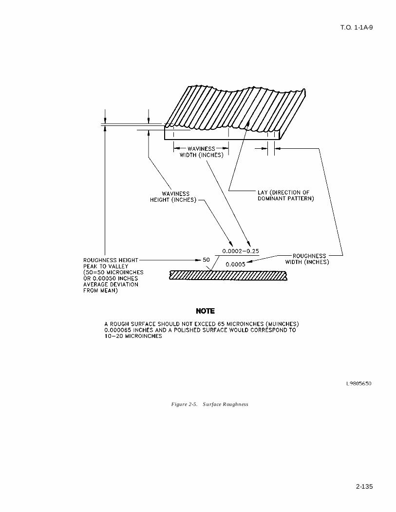
T.O. 1-1A-9
Figure 2-5. Surface Roughness
2-135
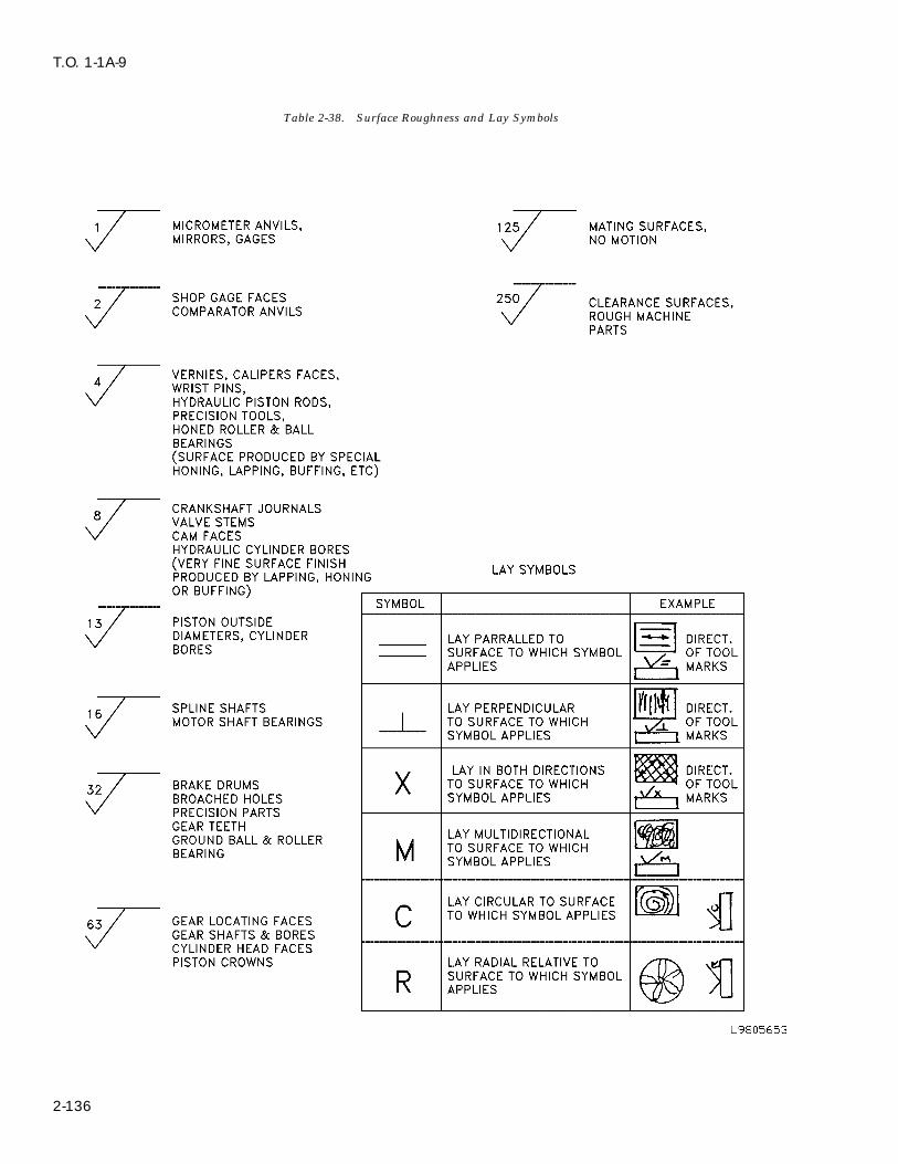
T.O. 1-1A-9
Table 2-38. Surface Roughness and Lay Symbols
2-136
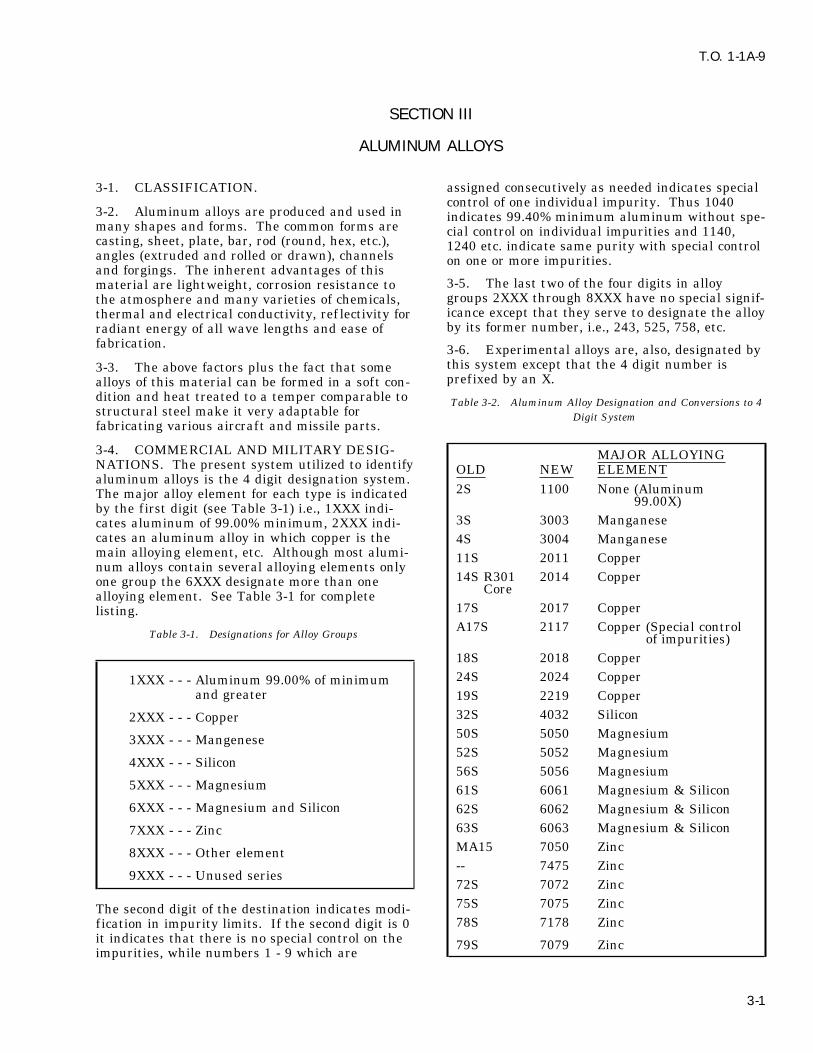
T.O. 1-1A-9
SECTION III
ALUMINUM ALLOYS
3-1. CLASSIFICATION. assigned consecutively as needed indicates specialcontrol of one individual impurity. Thus 1040
3-2. Aluminum alloys are produced and used in indicates 99.40% minimum aluminum without spe-many shapes and forms. The common forms are cial control on individual impurities and 1140,casting, sheet, plate, bar, rod (round, hex, etc.), 1240 etc. indicate same purity with special controlangles (extruded and rolled or drawn), channels on one or more impurities.and forgings. The inherent advantages of this
3-5. The last two of the four digits in alloymaterial are lightweight, corrosion resistance togroups 2XXX through 8XXX have no special signif-the atmosphere and many varieties of chemicals,icance except that they serve to designate the alloythermal and electrical conductivity, ref lectivity forby its former number, i.e., 243, 525, 758, etc.radiant energy of all wave lengths and ease of
fabrication. 3-6. Experimental alloys are, also, designated bythis system except that the 4 digit number is3-3. The above factors plus the fact that someprefixed by an X.alloys of this material can be formed in a soft con-
dition and heat treated to a temper comparable to Table 3-2. Aluminum Alloy Designation and Conversions to 4structural steel make it very adaptable for Digit System fabricating various aircraft and missile parts.
3-4. COMMERCIAL AND MILITARY DESIG- MAJOR ALLOYINGNATIONS. The present system utilized to identify OLD NEW ELEMENTaluminum alloys is the 4 digit designation system.
2S 1100 None (AluminumThe major alloy element for each type is indicated 99.00X)by the first digit (see Table 3-1) i.e., 1XXX indi-3S 3003 Manganesecates aluminum of 99.00% minimum, 2XXX indi-
cates an aluminum alloy in which copper is the 4S 3004 Manganesemain alloying element, etc. Although most alumi- 11S 2011 Coppernum alloys contain several alloying elements only
14S R301 2014 Copperone group the 6XXX designate more than one Corealloying element. See Table 3-1 for complete17S 2017 Copperlisting.A17S 2117 Copper (Special control
Table 3-1. Designations for Alloy Groups of impurities)18S 2018 Copper24S 2024 Copper1XXX - - - Aluminum 99.00% of minimum
and greater 19S 2219 Copper32S 4032 Silicon2XXX - - - Copper50S 5050 Magnesium3XXX - - - Mangenese52S 5052 Magnesium
4XXX - - - Silicon56S 5056 Magnesium
5XXX - - - Magnesium 61S 6061 Magnesium & Silicon6XXX - - - Magnesium and Silicon 62S 6062 Magnesium & Silicon
63S 6063 Magnesium & Silicon7XXX - - - ZincMA15 7050 Zinc8XXX - - - Other element-- 7475 Zinc
9XXX - - - Unused series72S 7072 Zinc75S 7075 ZincThe second digit of the destination indicates modi-78S 7178 Zincfication in impurity limits. If the second digit is 0
it indicates that there is no special control on the 79S 7079 Zincimpurities, while numbers 1 - 9 which are
3-1

T.O. 1-1A-9
NOTE 3-11. Alloys alclad 2014, 2024, alclad 2024, 6061,7075, alclad 7075 and 7178 are classed as heatCladding which is a sacrificial alumi-treatable. The mechanical properties of thesenum coating applied to an aluminumalloys is improved by heat treatment or by a com-alloy core for the purpose of increas-bination of heat treatment and strain hardening.ing corrosion resistance is designatedThe tempers for these alloys is designated by sym-as alclad 2024, alclad 2014, alcladbols, W, T, T2, T3, T4, T5, T6, T7, T8, T9, T10, F7075, etc.and O. Following is a summary of these symbols.
3-7. Aluminum alloys for military use are identi--F As fabricatedfied by military and federal specifications which-O Annealedare comparable to commercial specifications and-W Solution heat treated - unstable temperdesignations. The following table is a general list-T Treated to produce stable tempers other than -Fof the commonly used military and federal specifi-
or -Ocations according to the commercial designation-T2 Annealed (cast products only)and forms of material.-T3 Solution heat treated and then cold worked
3-8. MECHANICAL PROPERTIES. Prior to -T4 Solution heat treatedpresenting factual data on mechanical properties -T5 Artificially aged onlythe tempers (hardness) and methods of designation -T6 Solution heat treated and then artificiallyshould be explained. For nominal mechanical agedproperties see Table 3-4. -T7 Solution heat treated and stabilized
-T8 Solution heat treated, cold worked and then3-9. The tempers of aluminum alloys are pro-artificially agedduced essentially by three methods. These meth-
-T9 Solution heat treated, artif icially aged, andods are cold working (strain hardening), heatthen cold workedtreatment and a combination of the two. The vari-
-T10 Artificially aged and then cold workedous alloys of aluminum are either classed as heat-treatable or non-heat-treatable. Alloys 1100, 3003, Added numbers to the above denotes a modifica-alclad 3003, 3004, alclad 3004, 5050 and 5052 are tion of standard tempers. Example: The numeralclassed as nonheat-treatable. The tempers of ‘‘6’’ following ‘‘T3’’ indicates a different amount ofthese alloys are designated by symbols H1, H2, cold work then used in ‘‘T3’’ such as 2024-T36.H3, H4, F & O. The numbers added to indicate modification or sig-
nificant alternation of the standard temper are3-10. A second number added to the above indi-arbitrarily assigned and specification for the alloycates the degree of strain hardening-actualshould be utilized to determine specific data.temper.
Example: 2=1/4 hard (2/8) - H12, H22, H32 3-12. The following standard modification digits4=1/2 hard (4/8) - H14, H24, H34 have been assigned for wrought products in all6=3/4 hard (6/8) - H16, H26, H36 alloys: TX-51 - Stress-Relieved by Stretching:8=Full Hard (8/8) - H18, H28, H38 Applies to products which are stress-relieved by
stretching the following amounts after solutionAs previously pointed out the above tempers desig- heat treatment:nation symbols are hyphen (-dash) suffixed to the4 digit alloy designation. Example: 1000-H12, Plate 1 1/2 to 3% permanent set5052-H24, 3004-H34 etc. The general symbols
Rod, Bar and Shapes 1 to 3% permanent setused for the nonheat-treatable alloys are asfollows:
Applies directly to plate and rolled or cold finishes-F As fabricated rod and bar. These products receive no further-O Annealed straightening after stretching. Applies to-H21 Strain hardened only extruded rod, bar and shapes which receive minor-H2 Strain hardened then partial annealed straightening after stretching to comply with stan--H3 Strain hardened then stabilized dard tolerances.
-TX510 - Applies to extruded rod, bar and shapesNOTE which receive no further straightening
Attempt should not be made to alter after stretching.the temper characteristics of the ‘‘H’’ -TX511 - Applies to extruded rod, bar and shapesseries of aluminum alloys other than which receive minor straightening afterin emergencies. This shall be limited stretching to comply with standardto annealing operation only. tolerances.
3-2

T.O. 1-1A-9
Table 3-3. Federal and Military Specifications
ALLOY FORM (COMMODITY) AMS FEDERAL MILITARY
1100 Bars Rolled 4102 QQ-A-411, QQ-A-225/1 -Bar, rod, wire and shapes,rolled or drawn QQ-A-411, QQ-A-225/1 -Sheet and Plate 4001B,4003B QQ-A-561, QQ-A-250/1 -Tubing 4062C WW-T-783 (Old), WW-T- -
700/1* - - MIL-A-148
Extrusion (Impact) - - MIL-A-12545
1360 Wrought Product - - MIL-A-799
2011 Bar and Rod - QQ-A-365, QQ-A-225/3 -
2014 Bar, Rod and ShapesExtruded 4153A QQ-A-261, QQ-A-200/2
Bar, Rod and ShapesRolled or Drawn 4121B QQ-A-266, QQ-A-225/4
Forgings 4134A,4135H QQ-A-367
Extrusions (Impact) (See QQ-A-367 & 367-1) MIL-A-12545
Alclad QQ-A-255, QQ-A-250/32014 Plate and Sheet
2017 Bar, Rod, Wire and Shapes,Rolled or Drawn 4118 QQ-A-351, QQ-A-225/5
WIRE - ROD QQ-A-430 MIL-W-7986
FORGINGS QQ-A-367
2018 Forgings 4140 QQ-A-367
2020 Sheet and Plate QQ-A-250/16 MIL-A-8882
2024 Bar, Rod and Shapes 4152 QQ-A-267, QQ-A-200/3
Extruded
Bar, Rod and ShapesRolled or Drawn 4120 QQ-A-225/6, QQ-A-268
2024 Plate and Sheet 4035 QQ-A-355, QQ-A-250/44037
3-3

T.O. 1-1A-9
Table 3-3. Federal and Military Specifications - Continued
ALLOY FORM (COMMODITY) AMS FEDERAL MILITARY
Alclad2024 Sheet and Plate 4040 QQ-A-362, QQ-A-250/5
40414042
2024 Tube Drawn 4086 WW-T-785 (Old),4087 WW-T-700/34088
2025 Forgings 4130 QQ-A-367
2218 Forgings 4142 QQ-A-367
2219 Plate and Sheet MIL-A-8720
Sheet and Plate 4031 QQ-A-250/304090
Sheet and Plate, 4094Alclad 4095
4096
Extrusions 41624163
3003 Bar, Rod, Shapes QQ-A-200/1, NewExtruded QQ-A-357, Old
Bar, Rod, Wire andShapes QQ-A-225/2 (New)Rolled or Drawn QQ-A-356 (Old)
Plate and Sheet 4006 QQ-A-359, QQ-A-250/24008
Tube Drawn 4065 WW-T-786 (Old)4067 WW-T-700/3
4032 Forgings 4145 QQ-A-367
5052 Bar, Rod, Wire QQ-A-225/7 (New)and Shapes Drawn 4114 QQ-A-315 (Old)
5052 Plate and Sheet 4015 QQ-A-3184016 QQ-A-250/84017
Tube, Drawn 4070 WW-T-787 (Old),4071 WW-T-700/4
5056 Bar, Rod and Wire 4182 MIL-C-915Rolled or Drawn (Ships)
3-4

T.O. 1-1A-9
Table 3-3. Federal and Military Specifications - Continued
ALLOY FORM (COMMODITY) AMS FEDERAL MILITARY
5056 Bar, Rod, Shapes- QQ-A-200/7 MIL-C-6136(Cont) Extruded
Plate Sheet QQ-A-250/9
Wire Rod MIL-W-7986
Welding Rod QQ-R-566 C1FS-RA156
5083 Bar, Rod and Shapes QQ-A-200/4 (New) MIL-A-19005
Plate and Sheet QQ-A-250/8 (New) MIL-A-87001MIL-A-17358
5086 Plate and Sheet QQ-A-250/7 (New) MIL-A-19070
5154 Plate and Sheet 4018 MIL-A-173574019
6061 Bar, Rod and ShapesExtruded 4150 QQ-A-270
Bar, Rod and Shapes QQ-A-225/8 (New)Rolled or Drawn QQ-A-325 (Old)
6061 Forgings 4127 QQ-A-367d-1
Plate and Sheet 4025 QQ-A-3274026 QQ-A-250/11 (New)4027
Tube, Drawn 4080 WW-T-789/WW-T-700/64082
Tube, Hydraulic 4081 MIL-T-7081
Alclad6061 Sheet and Plate 4021
40224023
6062 Bar, Rod and Shapes 4155 QQ-A-270 (Old)Extruded QQ-A-200/8 (New)
Tube, Drawn 409140924093
Tube, Hydraulic MIL-T-7081
6063 Bar, Rod and Shapes QQ-A-200/9 (New)Extruded 4156 QQ-A-274 (Old)
6066 Bar, Rod and ShapesExtruded
3-5

T.O. 1-1A-9
Table 3-3. Federal and Military Specifications - Continued
ALLOY FORM (COMMODITY) AMS FEDERAL MILITARY
6151 Forgings 4125 QQ-A-367
7050 Plate 40504201
Extrusion 434043414342
Die Forging 4107 MIL-A-46118D(Armor)
Hand Forging 4108
7075 Bar, Rod and Shapes QQ-A-225/11Extruded 4154 QQ-A-277
Bar, Rod, Shapesand Wire, Rolled QQ-A-225/9or Drawn 4122 QQ-A-282
Forgings 4139 QQ-A-367Extrusions (Impact) 4170 MIL-A-12545
Plate and Sheet 4044 QQ-A-2834045 QQ-A-250/12
Alclad7075 Plate and Sheet 4048 QQ-A-287
4049 QQ-A-250/13
Plate and SheetAlclad one side QQ-A-250/13 MIL-A-8902
7076 Forgings 4137 QQ-A-367 MIL-A-11352
7079 Forgings 4138 QQ-A-367
Plate and Sheet QQ-A-250/17
Plate and SheetAlclad one side QQ-A-250/18
7475 Sheet and Plate 42074202
Rod MIL-A-63547
7178 Bar and ShapesExtruded 4158 MIL-A-9186
Plate and Sheet 4051 QQ-A-250/14 MIL-A-91804052
8280 Sheet MIL-A-11267(ORD)
3-6

T.O. 1-1A-9
Table 3-3. Federal and Military Specifications - Continued
ALLOY FORM (COMMODITY) AMS FEDERAL MILITARY
99.75% Ingot QQ-A-45199.5%99.3%99.0%
43 Foundry Ingot QQ-A-371108A108113122A132
142 Foundry Ingot QQ-A-371195B195214220319355356
XB216 Foundry Ingot MIL-A-10937(ORD)
43 Sand Castings QQ-A-601
108 Sand Castings QQ-A-601
113 Sand Castings QQ-A-601
122 Sand Castings QQ-A-601
142 Sand Castings 4222 QQ-A-601
195 Sand Castings 4230 QQ-A-6014231
B214 Sand Castings QQ-A-601
XB216 Sand Castings MIL-A-10936(ORD)
220 Sand Castings QQ-A-601
319 Sand Castings 4240 QQ-A-601
355 Sand Castings 4210 QQ-A-60142124214
356 Sand Castings 4217
A612 Sand Castings MIL-A-10936(ORD)
ML Sand Castings MIL-A-25450USAF
43 Permanent Mold Castings QQ-A-596
A108 Permanent Mold Castings QQ-A-596
3-7

T.O. 1-1A-9
Table 3-3. Federal and Military Specifications - Continued
ALLOY FORM (COMMODITY) AMS FEDERAL MILITARY
113 Permanent Mold Castings QQ-A-596
122 Permanent Mold Castings QQ-A-596
A132 Permanent Mold Castings QQ-A-596
B195 Permanent Mold Castings 4282 QQ-A-5964283
XB216 Permanent Mold Castings MIL-A-10935(ORD)
319 Permanent Mold Castings QQ-A-596
355 Permanent Mold Castings 4280 QQ-A-5964281
356 Permanent Mold Castings 4284 QQ-A-5964286
750 Permanent Mold Castings 4275 QQ-A-596
ML Permanent Mold Castings
13 Die Castings 4290 QQ-A-591 MIL-A-15153Ships
43 Die Castings QQ-A-591 MIL-A-15153Ships
218 Die Castings QQ-A-591 MIL-A-15153Ships
360 Die Castings 4290 QQ-A-591
A360 Die Castings QQ-A-591 MIL-A-15153Ships
380 Die Castings QQ-A-591
A380 Die Castings 4291 QQ-A-591 MIL-A-15153Ships
Misc STANDARD/SPECIFICATIONS
-TX52 - Stress-Relieved by Compressing: Applies attain mechanical properties different fromto products which are stress-relieved by those of the -T6 temper.*compressing after solution heat treatment. *Exceptions not conforming to these definitions
are 4032-T62, 6101-T62, 6062-T62, 6063-T42 and-TX53 - Stress-Relieved by Thermal Treatment.6463-T42.
3-13. The following two digit - T temper designa- 3-14. For additional information on heat treatingtions have been assigned for wrought products in aluminum alloys, see paragraph 3-22.all alloys:
3-15. Chemical composition nominal plus generaluse data are given in Table 3-4 and nominal-T42 - Applies to products solution heat treated bymechanical properties at room temperature arethe user which attain mechanical propertiesgiven in Table 3-5. The values cited are generaldifferent from those of the -T4 temper.*and intended for use as comparisons values. For
-T62 - Applies to products solution heat-treated specific values the specification for the alloyand artificially aged by the user which should be utilized.
3-8

T.O. 1
-1A
-9
3-9
Table 3-4. Chemical Composition Nominal and General Use Data 1/
1 NOMINAL COMPOSITION - %
FLAT ANDALLOY SI CU MN MG CR ZN AL COILED
SHEET PLATE SHAPES TUBE PIPE CHARACTERISTICSRODSANDBARS
EC -- -- -- -- -- -- 99.45 X Electrical conductor
1060 0.25 0.05 0.03 0.03 -- 0.05 99.60 X Good corrosion resis-tance, electrical con-ductivity, formabilityand weldability.
1100 1.0 0.20 0.05 -- 0.10 0.10 99.0 X X X X Excellent formabili-ty, readily weldedand brazed, corrosionresistant.
1145 0.55 0.05 0.05 -- -- -- 99.45 X Excellent formabilitycombined with highelectrical and ther-mal conductivity andcorrosion resistant.
2014 0.8 4.5 0.8 0.4 0.10 0.25 REM X X X High strength alloy.Electric resistanceweldability excellentfusion weldabilitylimited.
2024 0.5 4.5 0.6 1.5 0.10 0.25 REM X X X Popular sheet alloyfor aircraft similarto 2014.

T.O. 1
-1A
-9
3-1
0 Table 3-4. Chemical Composition Nominal and General Use Data 1/ - Continued
1 NOMINAL COMPOSITION - %
FLAT ANDALLOY SI CU MN MG CR ZN AL COILED
SHEET PLATE SHAPES TUBE PIPE CHARACTERISTICSRODSANDBARS
2219 0.1 6.2 0.3 0.01 - 0.05 REM X X X X Strutural uses re-quiring highstrength up to 600degrees F; highstrength weldments.
3003 0.6 0.20 1.2 -- -- 0.10 REM X X X X Stronger than 1100with good weldabilityand formability, highresistance to corro-sion.
3004 0.30 0.25 1.2 1.0 -- 0.25 REM X X Stronger than 1100and 3003 with fairworkability and goodcorrosion resistance.
5005 0.40 0.20 0.20 0.8 0.10 0.25 REM X X Similar to 3003 instrength. Good ano-dizing characteris-tics, formability andresistance to corro-sion.
5050 0.40 0.20 0.10 1.4 0.10 0.25 REM X X Good anodizingstrength, formability,weldability, and cor-rosion resistance.

T.O. 1
-1A
-9
3-1
1
Table 3-4. Chemical Composition Nominal and General Use Data 1/ - Continued
1 NOMINAL COMPOSITION - %
FLAT ANDALLOY SI CU MN MG CR ZN AL COILED
SHEET PLATE SHAPES TUBE PIPE CHARACTERISTICSRODSANDBARS
5052 0.45 0.10 0.10 2.5 0.25 0.10 REM X X Highest strength ofnon-heat-treatablealloys. Good corro-sion resistance andfinishing character-istics.
5083 0.40 0.10 0.8 4.5 0.15 0.25 REM X X High weld joint effi-ciency with basicgood strength andresistance combinedwith good formabili-ty.
5154 0.45 0.10 0.10 3.5 0.25 0.20 REM X X Good strength andexcellent weldability.
5254 0.45 0.05 0.01 3.5 0.25 0.20 REM X Good strength, weld-ability and corrosionresistance.
5357 0.12 0.07 0.3 1.0 -- -- REM X Excellent bright f in-ishing characteris-tics.
5454 0.40 0.10 0.8 2.7 0.2 0.25 REM X X X Excellent strength atelevated temperature(150 -300 F) plusweldability.
5456 0.40 0.20 0.8 5.3 -- -- REM X X High strength andcorrosion resistance,weldable.

T.O. 1
-1A
-9
3-1
2 Table 3-4. Chemical Composition Nominal and General Use Data 1/ - Continued
1 NOMINAL COMPOSITION - %
FLAT ANDALLOY SI CU MN MG CR ZN AL COILED
SHEET PLATE SHAPES TUBE PIPE CHARACTERISTICSRODSANDBARS
5457 0.08 0.20 0.3 1.0 -- -- REM X Superior bright f in-ish when anodized.
5557 0.25 0.6 REM X Good bright finish-ing characteristics.Good weldability andformability.
5652 2.5 0.25 REM X Excellent strengthwith good finishingcharacteristics andcorrosion resistance.
6061 0.6 .25 0.15 1.0 .25 0.25 REM X X X X Best weldability ofheat treatable alloys,good formability andcorrosion resistance.
6062 0.6 .25 0.15 1.0 .06 0.25 REM X X Good weldabilitywith formability bet-ter than 6061.
6063 0.4 0.10 0.10 0.7 0.10 0.25 REM X X X Good finishing char-acteristics and resis-tance to corrosion.Good workabilitywith moderatestrength.

T.O. 1
-1A
-9
3-1
3
Table 3-4. Chemical Composition Nominal and General Use Data 1/ - Continued
1 NOMINAL COMPOSITION - %
FLAT ANDALLOY SI CU MN MG CR ZN AL COILED
SHEET PLATE SHAPES TUBE PIPE CHARACTERISTICSRODSANDBARS
7050 - 2.3 - 2.25 - 6.2 REM X X X X High tensile proper-ties, good exfoliationcorrosion resistancegood stress-corrosioncracking resistance.
7075 0.50 1.6 0.30 2.5 .3 5.6 REM X X X 2/ Extra highstrength and hard-ness. Electric resis-tance weldability butlimited fusion welda-bility.
7079 0.30 .6 .2 3.3 .2 4.3 REM X Similar to 7075 butmaximum strengthin thick sections.
7178 2.0 0.30 2.7 .3 6.8 REM X X High strength alloyfor a/c applications,however it is notchsensitive.
7475 0.05 1.5 0.03 2.25 2.1 5.7 REM X X Aerospace applica-tions requiring highstrength, toughnessup to 300 degrees Fresistance to stress-corrosion cracking.
SI = Silicon MN = Manganese CR = Chromium AL = Aluminum CU = Copper MG = Magnesium ZN = Zinc
1/ Nominal Composition Does Not Include All Alloying Elements That May Pertain, Specification Should Be Utilized When SpecificData Required.
2/ 7075 - T73 Is Completely Resistant To Stress Corrosion Cracking.

T.O. 1-1A-9
Table 3-5. Mechanical Properties - Typical
Yield Elongation, Per BrinellAlloy Tensile Strength Cent in 2 in. Hardness Shearingand Strength (Offset= Sheet Specimen 500-kg Load Strength
Temper PSI 0.2%) PSI (1/16 in. Thick) 10 MMM Ball PSI
1100-0 13,000 5,000 35 23 9,0001100-H12 16,000 15,000 12 28 10,0001100-H14 18,000 17,000 9 32 11,0001100-H16 21,000 20,000 6 38 12,0001100-H18 24,000 22,000 5 44 13,000
3003-0 16,000 6,000 30 28 11,0003003-H12 19,000 18,000 10 35 12,0003003-H14 22,000 21,000 8 40 14,0003003-H16 26,000 25,000 5 47 15,0003003-H18 29,000 27,000 4 55 16,000Alclad 3003
3004-0 26,000 10,000 20 45 16,0003004-H32 31,000 25,000 10 52 17,0003004-H34 35,000 29,000 9 63 18,0003004-H36 38,000 33,000 5 70 20,0003004-H38 41,000 36,000 5 77 21,000Alclad 3004
Alclad 2014-0 25,000 10,000 21 -- 18,000Alclad 2014-T3 63,000 40,000 20 -- 37,000Alclad 2014-T4 61,000 37,000 22 -- 37,000Alclad 2014-T6 68,000 60,000 10 -- 41,000
2024-0 27,000 11,000 20 47 18,0002024-T3 70,000 50,000 18 120 41,0002024-T36 72,000 57,000 13 130 42,0002024-T4 68,000 47,000 20 120 41,000Alclad 2024-0 26,000 11,000 20 -- 18,000Alclad 2024-T3 65,000 45,000 18 -- 40,000Alclad 2024-T36 67,000 53,000 11 -- 41,000Alclad 2024-T4 64,000 42,000 19 -- 40,000Alclad 2024-T81 65,000 60,000 6 -- 40,000Alclad 2024-T86 70,000 66,000 6 -- 42,000
2219-0 25,000 11,000 18 -- --2219-T42 52,000 27,000 20 -- --2219- 52,000 36,000 17 96 33,000T31,T3512219-T37 57,000 46,000 11 110 37,0002219-T62 60,000 42,000 10 113 37,0002219- 66,000 51,000 1 123 41,000T81,T8512219-T87 69,000 57,000 10 128 40,000
5005-0 18,000 6,000 30 28 11,0005005-H32 20,000 17,000 11 36 14,0005005-H34 23,000 20,000 8 41 14,0005005-H36 26,000 24,000 6 46 15,0005005-H38 29,000 27,000 5 51 16,000
3-14
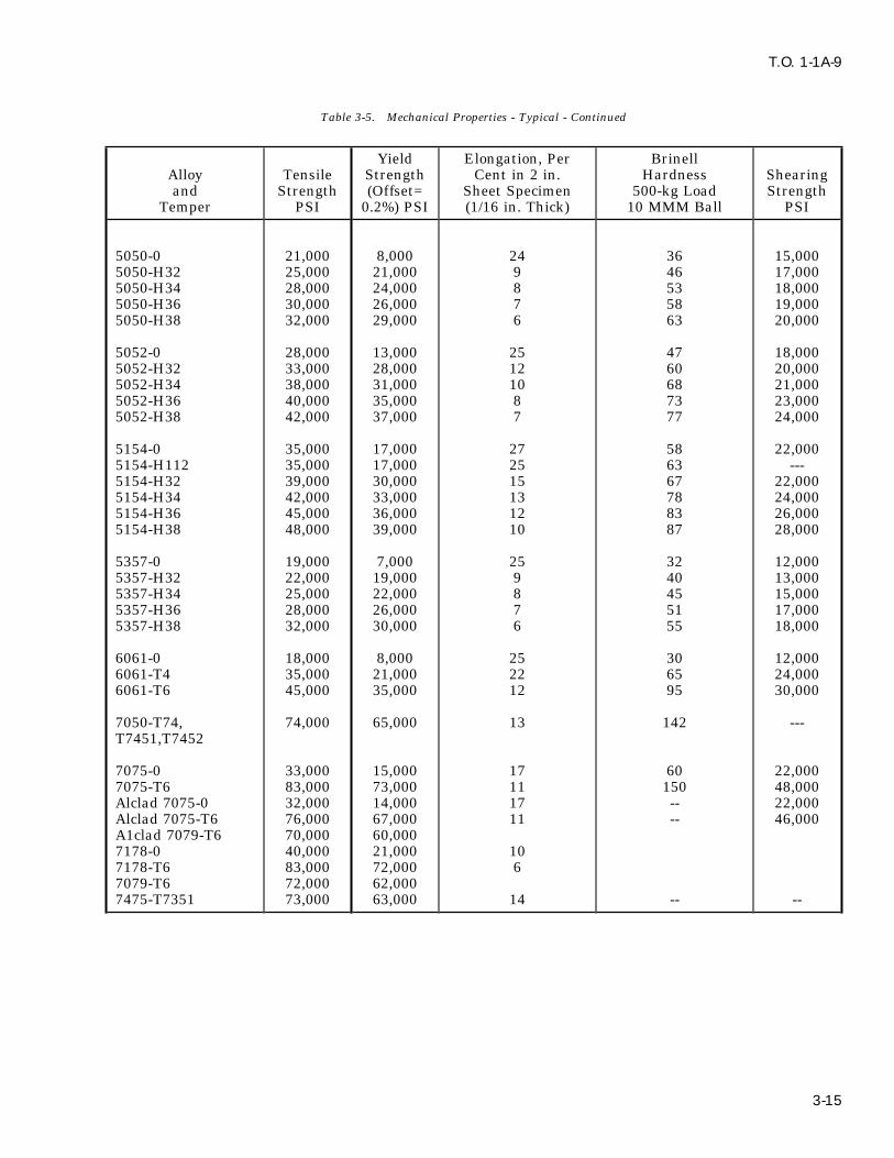
T.O. 1-1A-9
Table 3-5. Mechanical Properties - Typical - Continued
Yield Elongation, Per BrinellAlloy Tensile Strength Cent in 2 in. Hardness Shearingand Strength (Offset= Sheet Specimen 500-kg Load Strength
Temper PSI 0.2%) PSI (1/16 in. Thick) 10 MMM Ball PSI
5050-0 21,000 8,000 24 36 15,0005050-H32 25,000 21,000 9 46 17,0005050-H34 28,000 24,000 8 53 18,0005050-H36 30,000 26,000 7 58 19,0005050-H38 32,000 29,000 6 63 20,000
5052-0 28,000 13,000 25 47 18,0005052-H32 33,000 28,000 12 60 20,0005052-H34 38,000 31,000 10 68 21,0005052-H36 40,000 35,000 8 73 23,0005052-H38 42,000 37,000 7 77 24,000
5154-0 35,000 17,000 27 58 22,0005154-H112 35,000 17,000 25 63 ---5154-H32 39,000 30,000 15 67 22,0005154-H34 42,000 33,000 13 78 24,0005154-H36 45,000 36,000 12 83 26,0005154-H38 48,000 39,000 10 87 28,000
5357-0 19,000 7,000 25 32 12,0005357-H32 22,000 19,000 9 40 13,0005357-H34 25,000 22,000 8 45 15,0005357-H36 28,000 26,000 7 51 17,0005357-H38 32,000 30,000 6 55 18,000
6061-0 18,000 8,000 25 30 12,0006061-T4 35,000 21,000 22 65 24,0006061-T6 45,000 35,000 12 95 30,000
7050-T74, 74,000 65,000 13 142 ---T7451,T7452
7075-0 33,000 15,000 17 60 22,0007075-T6 83,000 73,000 11 150 48,000Alclad 7075-0 32,000 14,000 17 -- 22,000Alclad 7075-T6 76,000 67,000 11 -- 46,000A1clad 7079-T6 70,000 60,0007178-0 40,000 21,000 107178-T6 83,000 72,000 67079-T6 72,000 62,0007475-T7351 73,000 63,000 14 -- --
3-15

T.O. 1-1A-9
Table 3-6. Physical Properties-Standard Alloys
ALLOY SPECIFIC WEIGHTS APPROX ELECTRICAL CON-GRAVITY PER CU.IN. MELTING RANGE DUCTIVITY % COM-
DEGREES F PARE TO COPPERSTANDARD
1100-0 2.71 0.098 1,190-1,215 59
1100-H18 57
3003-0 50
3003-H12 2.73 0.099 1,190-1,210 42
3003-H14 41
3003-H18 40
3004-0 2.72 0.098 1,165-1,205 42
3004-H38 4250
2014-0 2.80 0.101 950-1,180 4030
2024-0 2.77 0.100 935-1,810 50
2024-T3 30
2219 2.84 0.102 1010-1190 44
5050-0 2.69 0.097 1,160-1,205 50
5050-H38 50
5052-0 2.68 0.097 1,100-1,200 35
5052-H38 35
5357-0 2.70 0.098 1,165-1,210 43
5357-H38 43
6061-0 2.70 0.098 1,080-1,200 45
6061-T4,T6 40
7050 2.83 0.102 890-1175 45
7075-0 2.80 0.101 890-1,180 --
7075-T6 30
7475 2.80 0.101 890-1175 46
BRASS 8.4-8.8 0.304-0.319 -- 26-43
Copper 8.94 0.322 1981 100
Monel 8.8 0.318 --- 4
Nickel 8.84 0.319 2645 16
Steel(low alloy) 7.6-7.8 0.276-0.282 2800 3-15
Steel(18.8 stainless) 7.92 0.283 2500-2650 2-4
Tin 7.3 0.265 449 15
Zinc 7.1 0.258 787 30
3-16

T.O. 1-1A-9
Table 3-7. Heat Treating (Soaking) Temperatures
SOLUTION HEAT TREATALLOY DESIGNATION TEMPERATURE (DEGREES F) TEMPER
WROUGHT ALLOYSExcept forgings alloys2014 925-945 2014-T42017 925-945 2017-T42117 925-950 2117-T42024 910-930 2024-W2219 985-1005 2219-T46061 960-1010 6061-T46062 960-1010 6062-T46066 960-980 6066-T47050 880-900 7050-W7075 (rolled or drawn) 860-930 7075-W7075 (Extruded) 860-880 7075-W7075 (Sheet .051 in thickness or less) 910-930 7075-W7178 (rolled or drawn) 860-930 7178-W7178 (Extruded) 860-880 7178-W*7079 820-840 7079-W
*7079 Other temperature may be required for certain sections and conditions.7475 880-970 7475-W
FORGINGS ALLOYS2014 925-950 2014-T42017 925-950 2017-T42018 940-970 2018-T4
FORGINGS2025 950-970 2025-T44032 940-970 4032-T46151 950-980 6151-T46061 960-1010 6061-T47075 360-890 7075-W
7075 Other temperatures may be required for certain sections and conditions.
7079 820-840 7079-W
7079 Other temperatures may be required for certain sections and conditions.
SAND CAST ALLOYS122 930-960 T4142 950-980 T4195 940-970 T4220 800-820 T4319 920-950 T4355 960-990 T4356 980-1010 T4
3-17

T.O. 1-1A-9
Table 3-7. Heat Treating (Soaking) Temperatures - Continued
SOLUTION HEAT TREATALLOY DESIGNATION TEMPERATURE (DEGREES F) TEMPER
40E Solution heat treatment not re-quired.PERMANENT MOLD CAST ALLOYS122 930-960 T4A132 940-970 T4142 950-980 T4B195 935-965 T4355 960-990 T4356 980-1010 T4
3-16. PHYSICAL PROPERTIES. Commercially low. To complete the solution often the metal ispure aluminum weights 0.098 pounds per cubic held at high temperatures for sufficient time; it isinch, corresponding to a specific gravity of 271. then quenched rapidly in cold water to retain thisData for standard alloys are shown in Table 3-6. condition. Immediately after quenching, the alloyThe approximate weight for aluminum, including is in an unstable condition, because it consists of aits alloys, is one-tenth of a pound per cubic inch supersaturated solid solution of the hardening(see Table 3-6). agent. Upon standing at room temperature the
hardening constituent in excess of that which is3-17. HEAT TREATMENT OF ALUMINUM soluble at room temperature precipitates. TheALLOYS. precipitate is in the form of extremely fine parti-
cles which due to their ‘‘keying’’ action, greatlyNOTE increase their strength. This is in effect a method
where the molecules of the aluminum and alloyingSAE-AMS-2772, Heat Treatment ofelements are realigned to increase the strengthAluminum Alloys, will be the controland hardness of some aluminum alloys.document for heat treatment of Alu-
minum Alloys used on aerospace 3-20. PRECIPITATION (AGE) HARDENING.equipment. For complete description This phase of heat treatment consists of agingof aluminum heat treat requirements, material previously subjected to solution heatrefer to latest issue of SAE-AMS- treatments by natural (occurs at room tempera-2772. ture) or artif icial aging. Artificial aging consistsof heating aluminum alloy to a specific tempera-3-18. GENERAL. There are two types of heatture and holding for a specified length of time.treatment applicable to aluminum alloys. TheyDuring this hardening and strengthening opera-are known as solution and precipitation heat treat-tion the alloying constituents in solid solution pre-ment. Some alloys such as 2017 and 2024 developcipitate out. As precipitation progresses, thetheir full mechanical properties as a result of solu-strength of the material increases until the maxi-tion heat treatment followed by 96 hours (naturalmum is reached. Further aging (overaging) causesprecipitation) aging at room temperature. Otherthe strength to decline until a stable condition isalloys, such as 2014, 7075, and 7178 require solu-obtained. The strengthening of the material is duetion heat treatment and aging (precipitation heatto the uniform alignment or formation of the mole-treatment) for specific length of time at a definitecule structure of the aluminum and alloyingtemperature (see Table 3-11).element.
NOTE 3-21. Artificial aged alloys are usually slightly‘‘overages’’ to increase their resistance to corrosion,Additional Heat Treatment informa-especially the high copper content alloys. This istion is discussed in Section IX.done to reduce their susceptibility to intergranular
3-19. Solution heat treatment is a process where corrosion caused by under-aging.the alloying elements enter into solid solution inthe aluminum at critical temperatures. It has 3-22. Natural aging alloys can be artif iciallybeen found that those alloying elements which aged, however, it increases the susceptibility of theincrease the strength and hardness are more solu- material to intergranular corrosion. If utilized itble in solid aluminum at high temperature than at should be limited to clad sheet, extrusions and
3-18 Change 4
T.O. 1-1A-9
similar items. For aging treatment, temperature 3-29. For clad sheet the number of solution heat-and times see Table 3-11. treatment is limited due to the increased diffusion
of the core and cladding. See Table 3-12 for the3-23. SOLUTION HEAT TREATMENT. As pre- recommended reheat-treatment times.viously pointed out it is necessary that solutionheat treatment of aluminum alloys be accom- 3-30. QUENCHING. The basic purpose forplished within close limits in reference to tempera- quenching is to prevent the immediate re-precipi-ture control and quenching. The temperature for tation of the soluble constituents after heating toheat treating is usually chosen as high as possible solid solution.without danger of exceeding the melting point of 3-31. To obtain optimum physical properties ofany element of the alloy. This is necessary to aluminum alloys, rapid quenching is required. Theobtain the maximum improvement in mechanical recommended time interval between removal fromproperties. the heat and immersion is 10 seconds or less.3-24. If the maximum specified temperature is Allowing the metal to cool before quenching pro-exceeded eutectic melting will occur. The conse- motes intergranular corrosion and slighty affectsquence will be inferior physical properties, and the hardness. This is caused by re-precipitationusually a severely blistered surface. If the temper- along grain boundaries and in certain slip planes.ature of heat treatment is low, maximum strength For specific quench delay see Table 3-10.will not be obtained. 3-32. There are three methods employed for3-25. Heating Time. The heating time commonly quenching. The one used depends upon the item,called the ‘‘soaking time’’ required to bring about alloy and properties desired.solution increases with the thickness of the section 3-33. Cold Water Quenching. Small articlesor part to be heat treated. Solution heat treatment made from sheet, extrusions, tubing and smallshould be held to the minimum time required to fairing are normally quenched in cold water. Theobtain the desired physical properties. In many temperature before quenching should be 85oF orinstances the above will require sample testing to less. Sufficient cold water should be circulateddetermine the exact solution time. For the recom- within the quenching tanks to keep the tempera-mended approximate soaking time for various ture rise under 20oF. This type of quench willalloys see Table 3-8. insure good resistance to corrosion and particu-3-26. The time at temperature (soaking time) is larly important when heat-treating 2017 and 2024.measured from the time the metal reaches the 3-34. Hot Water Quenching. Large forgings andminimum limit of the temperature range. In the heavy sections can be quenched in (150o - 180oF)case of thick material the controlling factor would or boiling water. This type of quench is used tobe when the center (core) reached the minimum minimize distortion and cracking which are pro-temperature. The soaking period will vary from 10 duced by the unequal temperatures obtained dur-minutes for thin sheet to approximately 12 hours ing the quenching operation. The hot waterfor the thicker materials, such as heavy forgings. quench will also reduce residual stresses whichA general guide to use is approximately one hour improves resistance to stress corrosion cracking.for each inch of cross-sectional thickness. It is rec-ommended that thermocouple be placed in the 3-35. Spray Quenching. Water sprays are usedcoldest part of the load to determine the period to quench parts formed from alclad sheet andrequired to bring the load to the correct tempera- large sections of most alloys. Principal reasons forture (soaking temperature). using this method is to minimize distortion and to
alleviate quench cracking. This system is not usu-3-27. The soaking temperature required is ally used to quench bare 2017 and 2024 due to theselected to put all of the soluble elements into effect on their corrosion resistance. The partssolid solution. With clad materials, prolonged heat- quenched by this media should pass the corrosioning may defeat the purpose of the cladding by test required for the item involved; (see specifica-excessive diffusion of copper and other soluble ele- tion SAE-AMS-2772).ments into the cladding.3-36. STRAIGHTENING OF PARTS AFTER3-28. RE-SOLUTION HEAT TREATMENT. The SOLUTION HEAT TREATMENTS. It will be nec-bare heat-treatable alloys can be solution heat essary to straighten some parts after heat treatingtreated repeatedly without harmful effects other due to warping produced by the process. Thesethan high temperature oxidation. The oxidation
can be retarded by using either sodium or potas-sium f luoborate during the heating cycle.
Change 4 3-19

T.O. 1-1A-9
parts are usually straightened by restriking or is accomplished. A temperature of 32oF or belowforming. It is desirable to place these parts in will delay or retard natural aging for approxi-refrigeration immediately after quenching to mately 24 hours, lower temperatures will delayretard natural aging until such time straightening the aging longer.
Figure 3-1. Head to Alloy Identification Method
3-37. HEAT TREATMENT OF RIVETS. The d. 1100 and 5056 Rivets. These do not requireheat-treatable alloys commonly used for rivets are heat treatment, install as received. See Figure 3-1,2117, 2017, and 2024. item A and 3-1, item B for identification.
a. 2117 Rivets. If supplied in T-4 temper nofurther treatment is required. The rivet is identi- CAUTIONf ied by a dimple in the center of the head (seeFigure 3-1, item AD for head identification). Rivets which have been anodically
oxide coated should not be reheat-b. 2017 or 2017-T4 (D) Rivets. Heat treattreated in direct contact with moltenprior to installation by heating to 940oF ± 10oF forsalts more than 5 times.30 minutes in a circulating air furnace, 1 hour in
still air furnace, or 30 minutes in a molten salt e. 7050 (E) Rivets. These do not require heatbath and quench in water. These rivets must be treatment, install as received. See Figure 3-1,driven within 20 minutes after quenching or item E for head identification.refrigerate at 32oF or lower which will delay the
f. D/DD Rivets. These may be stored inaging time 24 hours. If either time is exceededrefrigerators which ensure that the rivet tempera-reheat treatment is required. See Figure 3-1, itemture does not rise above minus 10oF. Rivets heldD for head identification. It is noted the D rivetsat minus 10oF or below can be retained for usemay also be used in the age hardened condition.indefinitely. When the rivets are transported,
c. 2024-0 or 2024-T4 (DD) Rivets. The same their temperature will be maintained at minusconditions apply for these rivets as for the 2017 10oF or below by being carried in refrigerated(D) except heat treat at 920oF ± 10oF. See Figure boxes.3-1, item DD for head identification.
3-20 Change 2

T.O. 1-1A-9
(1) Quality control shall be responsible for and immediately perform the forming or drawingperiodically checking the temperature of each operation.refrigerator and for prohibiting the use of rivets in 3-42. Recommended times and temperatures forany box when the temperature becomes excessive. annealing various alloys are as follows:
(2) Each refrigerator shall have the rivets a. Annealing of Work-Hardened Alloys. All ofremoved and be thoroughly cleaned at least once these alloys except 3003 are annealed by heatingevery six months. A tag or placard that denotes to 650oF and no higher than 775oF, holding atthe next cleaning date shall be attached to each temperature until uniform temperature has beenrefrigerator. established throughout the furnace load, and cool-(3) Rivets which remain out of refrigera- ing in air or in the furnace. Annealing tempera-
tion for 30 minutes or more shall be reheat ture shall not exceed 775oF to prevent excess oxi-treated. These rivets can be reheat treated a maxi- dation and grain growth. The 3003 alloy ismum of three times. annealed by heating to 775oF at a relatively rapid
rate and holding at the minimum soaking period3-38. ANNEALING. Aluminum alloys are necessary to attain temperature uniformity andannealed to remove the effects of solution heat then cool as cited above.treatment and strain hardening. Annealing is uti-
b. Annealing of heat-treated alloys (wrought).lized to help facilitate cold working. Parts workThese alloys (except 7075) are annealed by heatinghardened during fabrication are annealed at vari-to 775oF for not less than 1 hour and mostous stages of the forming operation so that compli-instances 2-3 hours. Material is then cooled at acated shapes can be formed. During prolongedrate of no greater than 50oF per hour until theforming or stamping operations the metal becomestemperature is 500oF or below. Rate of coolingstrain hardened (commonly called ‘‘work hard-below 500oF is not restricted; cool as desired.ened’’ and upon the performance of additionalAlloy 7075 is fully annealed by heating to 775oF -work it will split or crack.) When the above is850oF (higher temperature utilized for materialencountered it is usually necessary to anneal thehaving smaller amount of cold work), soaking for 2part one or more times at progressive stages of thehours at temperature, cooling in air, reheating toforming operation, if the part is to be successfully450oF, holding at this temperature for 6 hours andcompleted.then cooling to room temperature. Alternate 7075annealing methods:
CAUTION (1) If forming is to be accomplished imme-diately after annealing, heat to 775oF, 2-3 hours;
Annealed aluminum parts shall not air cool.be used for parts or f ittings on air-
(2) If alloy is to be stored for an extendedcraft or missiles unless specified byperiod before forming, heat to 670oF - 775oF, 2drawings or other approved engineer-hours; cool in air; reheat to 450oF; hold at thising data.temperature for 4 hours and then cool in air.
3-39. Time at temperature. This factor will vary(3) Intermediate anneal during cold work-depending upon the type of anneal (partial or full),
ing of ‘‘O’’ condition material; heat to 670o - 700oF,metal, thickness, method of furnace charging and1/2 hour maximum, or heat to 910o - 930oF untilsimilar factors. Avoid excessive time at tempera-uniform temperature is attained; cool in air. Ature to prevent growth, diffusion and discoloration,part shall not be annealed using the 910o - 930oFespecially when annealing clad alloys.temperature more than 3 times.
3-40. When fully annealing, no attempt should c. Annealing of cast alloys. Castings arebe made to shorten the annealing cycle because annealed by heating to 650o - 750oF holding forthe soluble constituents go into solution as the approximately 2 hours, and cooling to room tem-temperature is increased. If the material is then perature. The purpose of such annealing are forcooled rapidly the soluble constituents remain in the relief of stresses and attainment of dimen-solution and the material does not attain fully sional stability.annealed mechanical properties.
d. Partial annealing of heat-treated material.3-41. Annealing and subsequent forming of When heat-treated materials are annealed as spec-material previously heat treated should be avoided ified for annealing of the work-hardened alloys,if conditions and time permit. The recommended the effect of heat-treatment is reduced considera-method is to repeat the solution heat treatment bly, but not completely. The partially annealed
Change 1 3-21
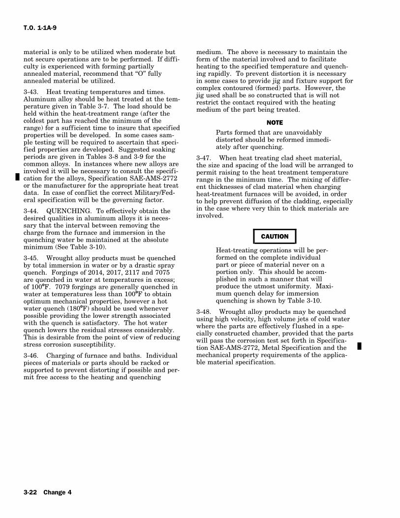
T.O. 1-1A-9
material is only to be utilized when moderate but medium. The above is necessary to maintain thenot secure operations are to be performed. If diff i- form of the material involved and to facilitateculty is experienced with forming partially heating to the specified temperature and quench-annealed material, recommend that ‘‘O’’ fully ing rapidly. To prevent distortion it is necessaryannealed material be utilized. in some cases to provide jig and fixture support for
complex contoured (formed) parts. However, the3-43. Heat treating temperatures and times. jig used shall be so constructed that is will notAluminum alloy should be heat treated at the tem- restrict the contact required with the heatingperature given in Table 3-7. The load should be medium of the part being treated.held within the heat-treatment range (after thecoldest part has reached the minimum of the NOTErange) for a sufficient time to insure that specified
Parts formed that are unavoidablyproperties will be developed. In some cases sam-distorted should be reformed immedi-ple testing will be required to ascertain that speci-ately after quenching.fied properties are developed. Suggested soaking
periods are given in Tables 3-8 and 3-9 for the 3-47. When heat treating clad sheet material,common alloys. In instances where new alloys are the size and spacing of the load will be arranged toinvolved it will be necessary to consult the specifi- permit raising to the heat treatment temperaturecation for the alloys, Specification SAE-AMS-2772 range in the minimum time. The mixing of differ-or the manufacturer for the appropriate heat treat ent thicknesses of clad material when chargingdata. In case of conf lict the correct Military/Fed- heat-treatment furnaces will be avoided, in ordereral specification will be the governing factor. to help prevent diffusion of the cladding, especially
in the case where very thin to thick materials are3-44. QUENCHING. To effectively obtain theinvolved.desired qualities in aluminum alloys it is neces-
sary that the interval between removing thecharge from the furnace and immersion in the
CAUTIONquenching water be maintained at the absoluteminimum (See Table 3-10). Heat-treating operations will be per-
formed on the complete individual3-45. Wrought alloy products must be quenchedpart or piece of material never on aby total immersion in water or by a drastic sprayportion only. This should be accom-quench. Forgings of 2014, 2017, 2117 and 7075plished in such a manner that willare quenched in water at temperatures in excess;produce the utmost uniformity. Maxi-of 100oF. 7079 forgings are generally quenched inmum quench delay for immersionwater at temperatures less than 100oF to obtainquenching is shown by Table 3-10.optimum mechanical properties, however a hot
water quench (180oF) should be used whenever 3-48. Wrought alloy products may be quenchedpossible providing the lower strength associated using high velocity, high volume jets of cold waterwith the quench is satisfactory. The hot water where the parts are effectively f lushed in a spe-quench lowers the residual stresses considerably. cially constructed chamber, provided that the partsThis is desirable from the point of view of reducing will pass the corrosion test set forth in Specifica-stress corrosion susceptibility. tion SAE-AMS-2772, Metal Specification and themechanical property requirements of the applica-3-46. Charging of furnace and baths. Individualble material specification.pieces of materials or parts should be racked or
supported to prevent distorting if possible and per-mit free access to the heating and quenching
3-22 Change 4
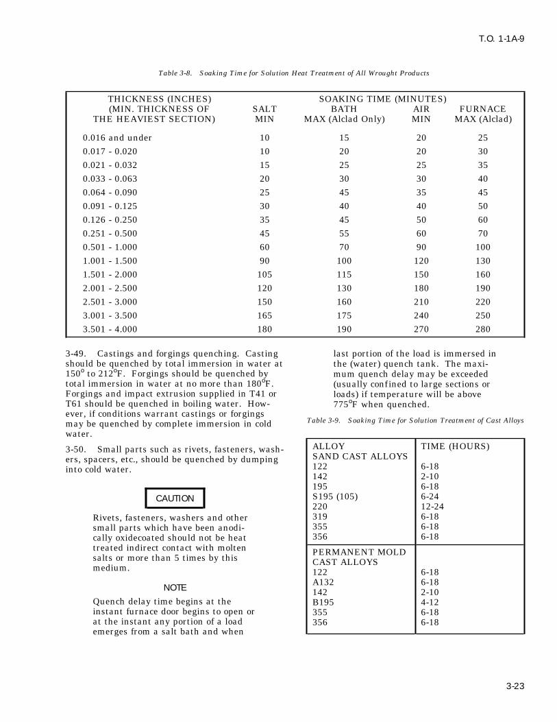
T.O. 1-1A-9
Table 3-8. Soaking Time for Solution Heat Treatment of All Wrought Products
THICKNESS (INCHES) SOAKING TIME (MINUTES)(MIN. THICKNESS OF SALT BATH AIR FURNACE
THE HEAVIEST SECTION) MIN MAX (Alclad Only) MIN MAX (Alclad)
0.016 and under 10 15 20 250.017 - 0.020 10 20 20 300.021 - 0.032 15 25 25 350.033 - 0.063 20 30 30 400.064 - 0.090 25 45 35 450.091 - 0.125 30 40 40 500.126 - 0.250 35 45 50 600.251 - 0.500 45 55 60 700.501 - 1.000 60 70 90 1001.001 - 1.500 90 100 120 1301.501 - 2.000 105 115 150 1602.001 - 2.500 120 130 180 1902.501 - 3.000 150 160 210 2203.001 - 3.500 165 175 240 2503.501 - 4.000 180 190 270 280
3-49. Castings and forgings quenching. Casting last portion of the load is immersed inshould be quenched by total immersion in water at the (water) quench tank. The maxi-150o to 212oF. Forgings should be quenched by mum quench delay may be exceededtotal immersion in water at no more than 180oF. (usually confined to large sections orForgings and impact extrusion supplied in T41 or loads) if temperature will be aboveT61 should be quenched in boiling water. How- 775oF when quenched.ever, if conditions warrant castings or forgings
Table 3-9. Soaking Time for Solution Treatment of Cast Alloysmay be quenched by complete immersion in coldwater.
ALLOY TIME (HOURS)3-50. Small parts such as rivets, fasteners, wash-SAND CAST ALLOYSers, spacers, etc., should be quenched by dumping122 6-18into cold water.142 2-10195 6-18S195 (105) 6-24CAUTION220 12-24319 6-18Rivets, fasteners, washers and other355 6-18small parts which have been anodi-356 6-18cally oxidecoated should not be heat
treated indirect contact with molten PERMANENT MOLDsalts or more than 5 times by this CAST ALLOYSmedium. 122 6-18
A132 6-18NOTE 142 2-10
Quench delay time begins at the B195 4-12instant furnace door begins to open or 355 6-18at the instant any portion of a load 356 6-18emerges from a salt bath and when
3-23

T.O. 1-1A-9
Table 3-10. Recommended Maximum Quench Delay, Wrought stretch or roll the material in order to produceAlloys (For Immersion Type these conditions.
Quenching) 3-56. HEAT TREATING EQUIPMENT. Equip-ment and heating media used are divided into two
NOMINAL THICKNESS MAXIMUM TIME distinct groups. They are liquid baths and con-(INCHES) (SECONDS) trolled atmosphere. Either method has certainup to 0.016 5 advantages over the other and it generally is0.017 to 0.031 7 advisable to weigh the advantages desired and0.032 to 0.091 10 consider environmental conditions.0.091 and over 15
3-57. The above are heated by gas, electricityand oil regardless of the method utilized it must3-51. HEAT TREATMENT.be demonstrated that satisfactory results are
3-52. PRECIPITATION (ARTIFICIAL AGE) obtained and the material is not injured.HEAT TREATMENT. Precipitation heat treatmentof many aluminum alloys is necessary to obtain 3-58. AIR FURNACES. Air furnaces are idealthe required properties. Heating of some alumi- for precipitation (aging), thermal treatments andnum alloys bare or alclad at an elevated tempera- annealing. These furnaces are also used for solu-ture, but well below the annealing temperature, tion heat treating. The initial cost of these typeafter solution heat treatment will result in tensile furnaces is higher than for the salt bath types, butand yield strength well above those obtained by they are usually more economical to operate, safer,room temperature aging. The above will also cleaner and more f lexible. Air furnaces used forapply to alloy 2024. However, this process will heat treatment of aluminum alloy should be of thereduce the elongation factor of the material and recirculating air type. The heated air in this typeincrease resistance to forming. Therefore, most furnace is recirculated at high velocities to obtainforming operations should be performed prior to a rapid heating cycle and uniform temperatures.this stage of treatment. The products of combustion must be excluded from
the furnace atmosphere to help avoid high temp3-53. Mechanical properties obtained from pre- oxidation and atmosphere contamination.cipitation (aging) are dependent on the amount ofcold work present in the material at the time of 3-59. SALT BATHS. The salt bathe method hasaging. The selection of material for various uses certain advantages over the air furnace. However,will therefore be governed by, the severity of the the advantages are usually confined to solutioncold work to be performed, strength and condition heat treatment only. Associated advantages areof the material required. uniform temperature without excess danger of
high temperature oxidation and faster heating3-54. Annealing or solution heat treating willwhich reduces the time required to bring the loadremove any properties developed as a result of coldto temperature. This method is adaptable for solu-working the material. Subsequent heat treatmenttion heat treating small parts, large thin sectionsand aging of annealed material or aging of solutionand missed loads. The above advantages may beheat treated material will result in T-6 condition,completely nullif ied by the slower quench causedprovided the material is not cold worked prior toby the necessary arrangement of equipment, f ireaging. The higher strength conditions can only beand explosion hazards, and decomposition of theobtained by a controlled amount of cold work priorsodium nitrate which when dissolved in quenchingto aging. Conditions T-81 or T-86 would necessi-water forms a compound that attacks aluminumtate a cold work percentage of approximately 1%alloys. The addition of potassium dichromatefor T-81 and 6% for T-86 after solution heat(approximately 1/2 ounce per hundred pounds oftreated and prior to aging.nitrate) tends to inhibit the attack.
3-55. Field accomplishment of the cold work3-60. Hollow core casting or parts where therequired to produce the higher strength conditionssalts are likely to be diff icult or impossible tois considered impractical. This is due to theremove should not be treated by bath salt.amount and types of equipment necessary to
3-24

T.O. 1-1A-9
Table 3-11. Precipitation (Aging) Treating Temperatures, Times and Conditions
ALLOY & TEMPER OR AGING TIME AGING TEMP TEMPERCOND BEFORE AGING (HOURS)2/ (DEGREES F)2/ AFTER AGING
WROUGHT ALLOYS(EXCLUDING FORGINGS)
2017 - as quenched(w) 96 room 2017-T4
2117 - as quenched(w) 96 room 2117-T4
2024 - as quenched(w) 3/ 96 room 2024-T4
6061 - as quenched(w) 96 room 6061-T4
6061-T4 71/2 - 81/2 340-360 6061-T6
2020-W 18 310-360 2020-T6
2024-T4 1-T42 16 370-380 2024-T6 1-T62
2024-T4 (Alternate for sheet) 11-13 370-380 2024-T6
2024-T3 11-13 370-380 2024-T81
2024-T36 7 - 9 370-380 2024-T86
2014-T4 1-T42 8 - 12 305-330 2014-T6 1-T62
2014-T4 (Alternate for Plate) 17-20 305-330 2014-T6
2219-T31/T351 17-19 350 2219-T81/T851
2219-T4 35-37 375 2219-T62
2219-W 96 room 2219-T4
6066-T4 71/2 - 81/2 340-360 6066-T6
6061-T4 71/2 - 81/2 340-360 6061-T6
7050-W 6-8 250 followed by 7050-T74350, 6-8 hours
7075-W 1/ 22 Minimum 240-260 7075-T6
7178-W 22 Minimum 240-260 7178-T6
6063-F 1-2 440-460 6063-T5
7079 - as quenched(w) 5 days at roomtemperaturefollowing 48hours at 230-250 degrees F
7475-W, Plate 24-25 250 7475-T6
7475-W, Sheet 3-5 250 followed by 7475-T61315, 3-3.25 hours
FORGING ALLOYS
2014-T4 5-14 340-360 2014-T6
2014 - as quenched 96 Minimum room 2014-T4
2017 - as quenched 96 Minimum room 2017-T6
Change 1 3-25

T.O. 1-1A-9
Table 3-11. Precipitation (Aging) Treating Temperatures, Times and Conditions - Continued
ALLOY & TEMPER OR AGING TIME AGING TEMP TEMPERCOND BEFORE AGING (HOURS)2/ (DEGREES F)2/ AFTER AGING
2018-T4 4-12 330-350 2018-T6
2025-T4 6-14 330-350 2025-T6
4032-T4 4-12 330-350 4032-T6
6151-T4 4-12 330-350 6151-T6
7075-W 22 Minimum 230-260 7075-T6
X7079 5 days at room X7079-T6temperature fol-lowed by 48 hoursat 230-250 degreesF
SAND CAST ALLOYS
142-T41 1-3 400-450 142-T61
195-T4 1-3 300-320 142-T6
S195-T4 1-4 300-320 S195-T6
220-W 96 Minimum room 220-T4
319-T4 1-6 300-320 319-T6
335-T4 1-6 300-320 335-T6
356-T4 1-6 300-320 356-T6
356-F 6-12 430-450 356-T6
40 9-11 345-365 40-E
40- 21 days room 40-E
PERMANENT MOLD CAST ALLOYS
142-T41 1-3 400-450 142-T61
B195-T4 1-8 300-320 B195-T6
319-T4 1-6 300-330 319-T6
355-T4 1-6 300-320 355-T6
356-T4 1-6 300-320 356-T6
A132-T45 14-18 300-350 A132-T65
1/ Alternate aging treatment for 7075-W sheet only; in thicknesses less than 0.500 inch: Heat at 230o-250oF for 3-4 hours, then heat 315o-335oF for 3-4 hours. The temperature may be raised directly fromthe lower to the higher temperature, or load may be allowed to cool between the two steps of thetreatment.
2/ Time is soak time after recorder is at temperature, for 0.500 inch thickness or less. Add 1/2 hour foreach additional 1/2 inch of thickness.
3/ The 96 hour minimum aging time required for each alloy listed with temper designation W is notnecessary if artif icial aging is to be employed to obtain tempers other than that derived from roomtemperature aging. (For example, natural aging (96 hours) to achieve the -T4 or -T42 temper for 2014alloy is not necessary prior to artif icial aging to obtain a -T6 or -T62 temper.)
3-26 Change 1

T.O. 1-1A-9
Table 3-12. Reheat Treatment of Alclad Alloys test locations within the furnace load area shouldbe checked, one in each corner, one in the centerand one for each 25 cubic feet of air furnace vol-
THICKNESS MAXIMUM NO. OF ume up to the maximum of 400 cubic feet. For(INCHES) REHEAT TREAT- salt bath the same as above except one test loca-MENT PERMISSI- tion for each 40 cubic feet of air volume, 40 testBLE locations are recommended. Other size furnaces
should be checked with a ratio of test locations in0.125 and less 1 accordance with those previously cited. A monthlysurvey should be made after the initial survey,over 0.125 2unless separate load thermocouples are employed,to record actual metal temperatures. However,periodic surveys shall be made as outlined for theNOTEinitial survey. The monthly survey should be
Heat treatment of a previously heat- made at one operating temperature for solutiontreated material is classified as a treatment and one for precipitation heat treat-reheat treatment. Therefore, the first ment. There should be a minimum of 9 test loca-heat treatment of material purchased tions with at least one for each 40 cubic feet ofin the heat treated condition is a heat treating volume. For all surveys, the fur-reheat treatment. Insofar as this naces should be allowed to heat to point of stabili-chart is concerned annealing and pre- zation before commencing the survey. The tem-cipitation treatments are not consid-
perature of all test locations should be determinedered heat treatments.at 5 to 10 minute intervals after insertion of the
3-61. Salt baths must be operated with caution temperature sensing elements in the furnace.to prevent explosions as any water on the material Temperature readings should be taken for a suffi-being treated is instantly transformed to steam cient length of time after thermal equilibrium toupon imersion in the salt bath. determine the recurring temperature pattern.
After all temperature sensing elements have3-62. Nitrate charged salt baths should not bereached equilibrium, the maximum temperatureused to heat-treat aluminum alloys types 5056 andvariation of all elements shall not exceed 20oF and220 due to the fact that the bath compound willat no time after equilibrium is reached should theattack the alloy.temperature readings be outside the solution heat
3-63. Temperature Control and Uniformity. treating or precipitation range being surveyed.Good temperature control is essential to produce
3-66. Temperature measuring instruments usedthe exacting temper requirements for superiorquality material. Upon bringing a change to tem- for furnace control shall not be used to read theperature, the furnace and the load should be con- temperature of the test temperature sensingtrollable with ±5oF of the required temperature elements.range. The design and construction of the fur-
3-67. Furnace thermocouple and sensing elementnaces and baths should be such that during theshould be replaced periodically. This is necessaryrecovery and soaking period, the air and metaldue to oxidation and deterioration of the elements.(load) temperature at any point in the working or
soaking area shall not exceed the maximum soak-3-68. Salt Bath Testing - Temperature uniform-ing temperature (see Table 3-7) for the specificity in a salt bath may be determined by use of aalloy being heat treated.temperature sensing element enclosed in a suita-
3-64. Furnace temperature survey. Furnace ble protected tube. The temperature sensing ele-equipment shall be installed with the necessary ment should be held in one position until thermalfurnace control, temperature measuring, and equilibrium has been substantially reached andrecording instruments to assure and maintain reading made. The temperature sensing elementaccurate control. should then be placed in a new location and the
procedure repeated. These operations should be3-65. Upon the initial installation and after eachrepeated until the temperature in all parts of thechange is made in the furnace which might affectbath have been determined. The maximum varia-the operational characteristics a temperature sur-tion indicated by reading from the various loca-vey should be made. The temperatures should betions in the load zone shall not exceed 20oF and nochecked at the maximum and minimum requiredreading shall be outside the heat treating rangefor solution and precipitation heat treatment for
which the furnace is to be used. A minimum of 9 specified for the materials involved.
3-27

T.O. 1-1A-9
3-69. At this point it should be explained that a b. Provide clean smooth (rust free) and adapt-substantial amount of the diff iculties encountered able forming equipment.in heating aluminum alloys is due to improper or
c. Sheared or cut edges shall be sanded andinadequate temperature control and circulation offiled or polished, prior to bending or forming.heating medium. When difficulties arise the func-
tion of these units should be checked prior to per- d. Use only straight and smooth forming diesforming other system test. or brake leafs of the correct radius which are free
of nicks, burrs and sharp edges.3-70. FABRICATION.e. Form material across the direction of grain
3-71. This portion is intended to provide some of f low when possible.the information required to fabricate the various
f. Material should be of the correct temper,aluminum products into parts and assemblies.thickness and alloy in the range of ‘‘formable’’Aluminum is one of the most workable of all thematerial.common metals. It can be fabricated into a variety
of shapes by conventional methods.3-77. For intricate forming operations it is neces-sary to use annealed (Con‘‘O’’) material and final3-72. The formability varies considerably withstrength developed by heat treating after thealloy and temper. Specific application usuallyforming has been accomplished. Heat-treateddepends on the shape, strength and temper of thealloys can also be formed at room temperaturealloy. The preceeding will necessitate that theimmediately after quenching (‘‘W’’temper), whichmechanic be well trained to cope with the vari-is much more formable than the fully heat-treatedables associated with this material especially whentemper. The part is then aged to develop fullthe end use of the item is an aircraft or a missile.strength. The forming operation should be per-
3-73. FORMING SHEET METAL. formed as soon after quenching as possible, inview of the natural aging that occurs at room tem-
3-74. GENERAL. The forming of aluminum perature on all the heat treatable alloys. The nat-(1100) is relatively easy, using approximately the ural aging can be delayed to a certain extent bysame procedures as those used for common steel placing the part in a cold storage area of 32o orexcept that care must be taken to prevent scratch- lower. The lower the temperature the longer theing. Do not mark on any metal surface to be used delay to a point where maximum delay isas a structural component with a graphite pencil obtained.or any type of sharp pointed instrument. Use pen-
3-78. BENDING. Bending is classified as singlecil, Aircraft Marking, Specification MIL-P-83953,curvature forming. Upon bending sheet metal, barNSN 7510-00-537-6928 (Black),7510-00-537-6930or rod, the material at the bends f lows or deforms(Yellow), and 7510-00-537-6935 (Red). All shopi.e., the material adjacent to the other surface ofequipment, tools and work area should be keptthe bend is under tension and the length issmooth, clean and free of rust and other foreignincreased due to stretching and the material adja-matter.cent to and on the inner surface is under compres-
3-75. Alloyed aluminum (2024, 7075, 7178, etc.) sion and the length is decreased.are more diff icult to form, and extensive control is
3-79. The most common problems encountered inrequired to prevent scratching and radii cracking.practice are springback and cracking within theScratching will make forming more diff icult plus itbend area. Problems associated with bend crack-provides an easy path for corrosion attack, espe-ing are usually a result of improper bend radii,cially on clad materials. The clad coating refer-rough edges of material being formed or formingenced is usually a sacrificial corrosion resistingequipment and bending parallel to direction ofaluminum alloy coating sandwiched metalurgicallygrain f low. For the approximate bend radius toto an alloyed core material. The thickness of theuse in bending various thicknesses and types ofcoating will depend on the thickness of the sheetaluminum see Table 3-13. Actual practice mayor plate. The nominal cladding thickness is 4% ofreveal that a larger or a smaller radius may becomposite thickness for material under 0.063 inch;used in some instances. If tighter bend radii is2.5% for material in the range of 0.063 - 0.187 inchrequired, then fabricators should proceed withand 1.5% for material 0.188 inch and thicker.additional caution and if needed, should seek
3-76. The following general rules should be assistance of engineering or laboratoryemployed in the handling and forming operation: metallurgists.
a. Provide clean area; free of chips, grit and 3-80. Difficulties encountered with springbackdirt and other foreign material. are most commonly associated with bending of the
3-28

T.O. 1-1A-9
stronger alloys, especially those having high yield required. Other means of reducing springback isstrength. Springback problem associated with this to bend the material in the soft condition (Condi-material can be overcome to a certain degree by tion ‘‘O’’) or immediately after quenching andoverforming. The amount of overforming utilized reducing the thickness or the radius if allowed.will depend on the temper and the alloy; the softer Avoid reducing radii to the point that grain sepa-the material the less springback compensation ration or bend cracking results.
Table 3-13. Cold Bend Radii (Inside) for General Applications
Alloy and Temper Sheet Thickness = T (Inches)
0.016 0.032 0.040 0.063 0.125 0.1875 0.250
1100-0 0.02 0.03 0.03 0.06 0.125 0.187 0.250
3003-0 0.03 0.03 0.06 0.06 0.160 0.187 0.250
5052-0 0.03 0.03 0.06 0.06 0.160 0.187 0.250
6061-0 0.03 0.03 0.06 0.06 0.16 0.1875 0.250
2014-0 0.03 0.06 0.09 0.09 0.19 0.312 0.44
2219-0 0 0 -- 0.5-1.5T 0.5-1.5T 0.5-1.5T 1-2T
7075-0 0.03 2T 2T 2T 2T 21/2T 3T
7178-0 0.03 2T 2T 2T 2T 21/2T 3T
1100-H12 0.02 0.03 0.03 1T 1T 11/2T 11/2T
3003-H12 0.03 0.03 0.03 1T 1T 11/2T 11/2T
5052-H32 0.03 0.06 0.06 11/2T 2T 21/2T 2T
1100-H16 0.03 0.06 2T 2T 2T 21/2T 3T
3003-H16 0.03 0.06 2T 2T 21/2T 4T 5T
5052-H36 0.03 0.06 2T 2T 21/2T 4T 5T
0.016 0.032 0.064 0.125 0.1875 0.250
1100-H18 0.03 2T 2T 21/2T 3T 31/2T
3003-H18 0.03 2T 2T 21/2T 3T 41/2T
5052-H38 0.03 2T 3T 4T 5T 6T
6061-T4 0.03 2T 2T 2T 3T 4T
6061-T6 0.03 2T 2T 2T 3T 4T
2219-T4 0-1T 0-1T 1-2T 1-2T 1.5-2.5T 1.5-2.5T
2219-T62,T81 2-3.5T 2.5-4T 3.5T 4-6T 4-6T 5-7T
2024-T4 0.06 4T 4T 5T 6T 6T
2024-T3 0.06 4T 4T 5T 6T 6T
2014-T3 0.06 3T 4T 5T 6T 6T
7075-T6 0.06 5T 6T 6T 6-8T 9-10T
7178-T6 0.06 5T 6T 6T 6-8T 9-10T
7050-T7 -- -- -- 8T 9T 9.5T
7475 -- -- -- -- -- --
3-29

T.O. 1-1A-9
3-81. DRAW FORMING. Draw forming is good spread between yield and tensile strength.defined as a method where a male die (punch) and Most of the common alloys are formed in thea female die is used to form a sheet blank into a annealed condition. It is possible to stretch formhollow shell. Draw forming is accomplished by the heat treatable alloys in tempers T4 or T6,forcing the male die and the metal blank into the where the shape is not too deep or where narrowfemale die. Generally mechanical press either width material is used. For the deeper curvedsingle or double action and hydraulic presses are shapes, the material is formed in the annealedused to perform the drawing operation. Results ‘‘O’’temper, heat treated and reformed, to elimi-will depend on die design, radii of die forming sur- nate distortion resulting from heat treatment. Asfaces, f inish of die, surface clearance between previously stated the material should be reformedpunch and female die, blank hold down pressure, as fast as possible after heat treatment. In someshape of blank, material allowance on blank, elon- instances the material is formed immediately aftergation factor of material, temper, shape of part heat treating and quenching. Selection of a sys-being formed, drawing speed, and lubricant. tem or condition of material to be utilized willOptium results usually requires experimentation require experimentation and the subsequent utili-and adjustment of one or more of these factors. zation of the system that gives the best results.Drawing of very deep shells require more experi-
3-86. HYDRAULIC PRESS FORMING. The rub-mentation and the utilization of a succession ofber pad hydropress can be utilized to form manylimit draws. Because of the work hardeningvarieties of parts from aluminum and its alloysresulting from each draw, reduction in successivewith relative ease. Phenolic, masonite, kirksitedraws must be less. In severe conditions an inter-and some types of hard setting molding plasticmediate anneal is sometimes used. Condition ‘‘O’’have been used successfully as form blocks tomaterial of the heat treatable alloys can be heatpress sheet metal parts such as ribs, spars, fans,treated after drawing to obtain higher strengthetc. The press forming operations are usuallyand to relieve the effect of work hardening. How-accomplished by setting the form block (normallyever, the non-heat treatable alloys can only bemale) on the lower press platen and placing a pre-annealed to relieve the effect of work hardening.pared sheet metal blank on the block. The blankThis material should not be annealed if highis located on the block with locating pins, to pre-strength is the major requirement.vent shifting of blank when the pressure is applied
3-82. The recommended material to manufacture (the sheet metal blank should be cut to size anddrawing dies is hardened tool steel for large scale edges deburred prior to pressing). The rubber padproduction; kirksite and plastic for medium or filled press head is then lowered or closed over theshort run production; and phenolic and hardwood form block and the rubber envelope, the form blockfor piece production. forcing the blank to conform to the form blocks
contour. This type forming is usually limited to3-83. STRETCH FORMING. This processrelatively f lat parts having f langes, beads andinvolves stretching a sheet or strip to just beyondlightening holes. However, some types of largethe elastic limit where permanent set will takeradii contoured parts can be formed with a combi-place with a minimum amount of springback.nation of hand forming and pressing operations.Stretch forming is usually accomplished by grip-It is recommended that additional rubber be sup-ping two opposite edges fixed vises and stretchingplemented in the form of sheets when performingby moving a ram carrying the form block againstthe above to prevent damage to the rubber pressthe sheet. The ram pressure being sufficient topad. The rubber sheet used should have a shorecause the material to stretch and wrap to the con-hardness of 50-80 durometers. The design of foamtour of the form block.block for hydropress forming require compensationfor springback even through the material normally3-84. Stretch forming is normally restricted toused is Condition ‘‘O’’ or annealed. Normal prac-relatively large parts with large radii of curvaturetice is to under cut the form block 2-7o dependingand shallow depth, such as contoured skin. Theon the alloy and radii of the form block.advantage is uniform contoured parts at faster
speed than can be obtained by hand forming with3-87. DROP HAMMER FORMING. The dropa yoder hammer or other means. Also, the condi-hammer can be used to form deep pan shaped andtion of the material is more uniform than thatbeaded type parts. Kirksite with a plastic surfaceobtained by hand forming. The disadvantage isinsert is satisfactory for male and female dies.high cost of initial equipment, which is limited toThe surface of kirksite dies used without plasticAMA level repair facilities.insert should be smooth to prevent galling andscratching of the aluminum surface. When form-3-85. Material used for stretch forming should being deep pans and complicated shaped parts it islimited to alloys with fairly high elongation and
3-30
T.O. 1-1A-9
often necessary to use drawings rings, pads or 2-3 removal of buckles and wrinkles in drawn shellstage dies. An intermediate anneal is sometimes shaped objects.used to relieve the hardened condition (cold work)
3-91. Forming by spinning is a fairly simple pro-resulting from the forming operation.cess, an aluminum disc (circle) is placed in a lathe
3-88. JOGGLING. A joggle is an offset formed to in conjunction with a form block usually made ofprovide for an overlap of a sheet or angle which is hardwood; as the disc and form block are revolved,projecting in the same plain. The inside joggle the disc is molded to the form block by applyingradii should be approximately the same as used pressure with a spinning stick or tool. Aluminumfor straight bending. Joggle run out or length as a soap, tallow or ordinary soap can be used as anormal rule should be three times the depth of the lubricant.joggle for the medium strength alloys (2024, 2014,
3-92. The best adapted materials for spinningetc.) and approximately four times the depth forare the softer alloys i.e., 1100, 3003, 5052, 6061,the higher strength alloys (7075, 7178, 7079 etc).etc. Other alloys can be used where the shape toWhere deep and tight joggles are required,be spun is not excessively deep or where the spin-annealed material should be used with heat treat-ning is done in stages and intermediate annealingment to follow.is utilized to remove the effect of strain hardening
3-89. HOT-FORMING. Hot forming is not gen- (work hardening) resulting from the spinning oper-erally recommended, however, it is sometimes ation. Hot forming is used in some instancesused where it is not possible to form an article by when spinning the heavier gauge materials andother methods. Accomplishment shall not be harder alloys.attempted unless adequate facilities are available
3-93. BLANKING AND SHEARING. Accurateto control temperature requirements. Actualshearing will be affected by the thickness of mate-formability will depend on the temperature thatrial, type of shear or knife blades, condition ofvarious alloys are heated. The higher the temper-material, adjustment and sharpness of blades, sizeature the easier formed. Excessively high temper-of cut and the relationship of the width of the cutature shall not be used, as considerable loss into sheet thickness.strength and corrosion resistance will occur. Fre-
quent checks should be made using an accurate 3-94. Normally most aluminum alloys can becontact pyrometer. Table 3-14 cites the recom- sheared 1/2 inch and less in thickness except formended times and temperature (accumulative) for the harder alloys i.e., 7075-T6 and 7178-T6. Thesethe various alloys. The losses in strength as a alloys have a tendency to crack in the vicinity ofresult of re-heating at the temperature cited by the cut especially if the sheer blades are dull orthis table will not exceed 5%. Equal formability nicked. The above will naturally require that tool-will be obtained with shorter periods of heating in ing used be designed to handle the thickness ofmost cases and the minimum times should be material to be cut. Correct clearance betweenused. It should be understood that this table cited shear blades is important for good shearing. Toothe maximum accumulative times at cited little clearance will quickly dull or otherwise dam-temperature. age the blades or knives; too much will cause thematerial to be burred, or even to fold between3-90. SPINNING. Spinning is an art and makesblades. Normal clearance is from one-tenth to one-exacting demands upon the skill and experience ofeighth the sheet thickness. Blade life will be pro-the mechanic performing the operation. For thislonged by occasionally lubricating. When thereason mass production of parts is impractical.capacity of shear is doubtful the shear manufac-However, it can be used to advantages where onlyturer should be consulted.a few parts are required and to assist in the
3-31
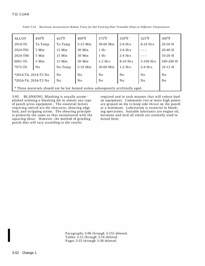
T.O. 1-1A-9
Table 3-14. Maximum Accumulative Reheat Times for Hot Forming Heat Treatable Alloys at Different Temperatures
ALLOY 450oF 425oF 400oF 375oF 350oF 325oF 300oF
2014-T6 To Temp To Temp 5-15 Min 30-60 Min 2-4 Hrs 8-10 Hrs 20-50 H
2024-T81 5 Min 15 Min 30 Min 1 Hr 2-4 Hrs - - - 20-40 H
2024-T86 5 Min 15 Min 30 Min 1 Hr 2-4 Hrs - - - 10-20 H
6061-T6 5 Min 15 Min 30 Min 1-2 Hrs 8-10 Hrs 5-100 Hrs 100-200 H
7075-T6 No No Temp 5-10 Min 30-60 Min 1-2 Hrs 2-4 Hrs 10-12 H
*2014-T4, 2014-T3 No No No No No No No
*2024-T4, 2024-T3 No No No No No No No
* These materials should not be hot formed unless subsequently artif icially aged.
3-95. BLANKING. Blanking is usually accom- required and in such manner that will reduce loadplished utilizing a blanking die in almost any type on equipment. Commonly two or more high pointsof punch press equipment. The essential factors are ground on die to keep side thrust on the punchrequiring control are die clearance, shearing edge at a minimum. Lubrication is essential in blank-lead, and stripping action. The shearing principle ing operations. Suitable lubricants are engine oil,is primarily the same as that encountered with the kerosene and lard oil which are normally used insquaring shear. However, the method of grinding mixed form.punch dies will vary according to the results
Paragraphs 3-96 through 3-155 deleted.Tables 3-15 through 3-16 deleted.Pages 3-33 through 3-38 deleted.
3-32 Change 1


T.O. 1-1A-9
3-156. Deleted. 3-165. Rivets in aluminum alloys 1100(A),5056(B), 2117(AD) are used in the condition3-157. Deleted. received Alloys 2017(D) and 2024(DD) oftenreferred to as ‘‘Ice Box Rivets’’ require heat treat-3-158. Deleted.ment prior to use (see paragraph 3-43). Rivets in
3-159. Deleted. alloy 2017 and 2024 should be driven immediatelyafter quenching with a maximum delay of 20 min-3-160. Deleted.utes or refrigerated to delay aging. The customary
3-161. Deleted. procedure (unless only a few rivets are involved) isto place the rivets under refrigeration immediately3-162. RIVETING. Riveting is the most commonafter heat treatment The time the rivets may bemethod of assembling components fabricated fromused will depend on refrigeration equipment avail-aluminum. Typical advantages of this method ofable. Cooling to 32oF will retard natural aging tomechanical fastening are simplicity of application,the extent that the rivets may be driven up to 24consistent joint uniformity, easily inspected (X Rayhours. Cooling rivets +0-10oF and below willand other type equipment not required.), low cost,retard natural aging to the extent that the rivetsand in many cases lighter weight.may be retained for use indefinitely.
3-163. The rivets used in USAF Weapon System3-166. Rivets utilized with extended driving timestructures require that the alloys and shapes beshould be closely inspected after upsetting forclosely controlled by specification/standards, tocracks. If inspection reveals that rivets areassure structural integrity and uniformity. Thesecracked, discontinue use, remove defective rivetsrivets are presently classified as solid shank, hi-and obtain reheat treated rivets prior to continu-shear, blind (structural-non-structural) explosive/ing the assembly operation.chemical expanded. They are available in a vari-
ety of shapes, alloys, sizes, lengths and types. The 3-167. If for some reason it is necessary to deter-most common alloys utilized are aluminum mine if a rivet has been heat treated this may bebecause the structure alloys are normally alumi- done by Rockwell Hardness testing. Test by sup-num. In addition some of the aluminum rivet porting rivets in a vee block and hardness readingcharacteristics can be changed by heat treating taken with a 1/16 inch ball 60 kilogram load . Awhich facilitates application (see paragraph 3-37.) hardness of over 75 will indicate a heat treated
rivet.3-164. All of the aluminum alloys could be usedto manufacture rivets; however, due to some alloyshaving superior properties they have been selectedas standard. See Table 3-17 for alloys head, iden-tif ication, MS/AN standard cross references, etc.,for general rivets used on AF weapons systems.
(3-39 blank)/3-40 Change 1
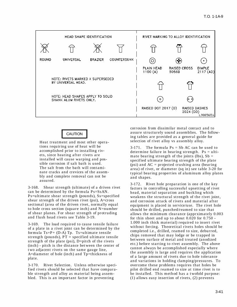
T.O. 1-1A-9
corrosion from dissimilar metal contact and toassure structurely sound assemblies. The follow-CAUTIONing tables are provided as a general guide forselection of rivet alloy vs assembly alloy.Heat treatment and most other opera-
tions requiring use of heat will be 3-171. The formula Ps = Sb AC can be used toaccomplished prior to installing riv- determine failure in bearing strength. Ps = ulti-ets, since heating after rivets are mate bearing strength of the joints (lbs), Sb =installed will cause warping and pos- specified ultimate bearing strength of the platesible corrosion if salt bath is used. (psi) and AC = projected crushing area (bearingThe salt from the bath will contami- area) of rivet, or diameter (sq in) see table 3-20 fornate cracks and crevices of the assem- typical bearing properties of aluminum alloy platesbly and complete removal can not be and shapes.assured.
3-172. Rivet hole preparation is one of the key3-168. Shear strength (ultimate) of a driven rivet factors in controlling successful upsetting of rivetcan be determined by the formula Ps=SsAN. head, material separation and buckling whichPs=ultimate shear strength (pounds), Ss=specified weakens the structural strength of the rivet joint,shear strength of the driven rivet (psi), A=cross and corrosion attack of rivets and material aftersectional (area of the driven rivet, normally equal equipment is placed in service/use. The rivet holeto hole cross section (square inch) and N=number should be drilled, punched/reamed to size thatof shear planes. For shear strength of protruding allows the minimum clearance (apprximately 0.003and f lush head rivets see Table 3-19. for thin sheet and up to about 0.020 for 0.750 -
1.000 inch thick material) required to insert rivet3-169. The load required to cause tensile failurewithout forcing. Theoretical rivets holes should beof a plate in a rivet joint can be determined by thecompleted i.e., drilled, reamed to size, deburred,formula Ts=P+ (D-A) Tp. Ts=ultimate tensilechips removed that may lodge or be trapped instrength (pounds), PT = specified ultimate tensilebetween surface of metal and treated (anodizedstrength of the plate (psi), D=pitch of the rivetsetc.) before starting to rivet assembly. The above(inch) - pitch is the distance between the center ofcannot always be accomplished especially wheretwo adjacent rivets on the same gauge line,the assembly is large and requires the applicationA=diameter of hole (inch) and Tp=thickness ofof a large amount of rivets due to hole toleranceplate.and variations in holding clamping/pressures. To
3-170. Rivet Selection. Unless otherwise speci- overcome these problems requires that holes befied rivets should be selected that have compara- pilot drilled end reamed to size at time rivet is toble strength and alloy as material being assem- be installed. This method has a twofold purpose:bled. This is an important factor in preventing (1) allows easy insertion of rivets, (2) prevents
3-41

T.O. 1-1A-9
elongation of rivet holes and resulting weakening chromate primer or other approved material. Twoof rivet joint. methods for coating rivets and improving protec-
tion of hole surfaces from corrosion are:3-173. Rivet holes drilled/reamed after assemblyis started should be treated by coating with zinc
Table 3-17. General Rivet (Alum) Identification Chart
SUPERSEDING HEAD AND HEATOLD AN/ MS STD FORM MATER- NUMERICAL CONDITION TREAT
STD IAL IDENTCODE
AN456 MS20470 Brazier Head SeeSolid Modified AN470
USAF460 See MS20601 1000 Flush Head SeeBlind Type II MS20601Class 2
USAF461 See MS20600 Protruding Head SeeType II Class I MS20601Blind
USAF463 See MS20600 Same Same
NAF1195 See MS20600 Same Same
AN470 MS20470 1100 A-Plain F NoUniversal HeadSolid 5056 B-Raised F No
Cross
2117 AD-Dimple T-4 No
2017 D-Raised T-4 YesDot
2024 DD-Raised T-4 YesDash
MS20600 5056 B F NoProtrudingHead-Blind 2117 AD T-4 NoType II,Class I Monel M No
MS20601 5056 B F No100o FlashHead Blind 2117 AD T-4 NoType II,Class 2 Monel M No
MS20602 5056 B F NoProtrudingHead BlindChemicallyExpanded Type 2017 D T-4 NoI, Class I,Styles A & B
3-42

T.O. 1-1A-9
Table 3-17. General Rivet (Alum) Identification Chart - Continued
SUPERSEDING HEAD AND HEATOLD AN/ MS STD FORM MATER- NUMERICAL CONDITION TREAT
STD IAL IDENTCODE
MS20604 5056 B F NoUniversal HeadBlind Class I 2117 AD T-4 NoNon Struct
Monel M or NoMP (MP =Monel Plated)
MS20605 5056 B F No100o FlashHead Blind 2117 AD T-4 NoClass 2, NonStruct Monel M or No
MP (MP =Monel Plated)
MS20606 5056 B F NoModifiedTrusshead 2117 AD T-4 NoBlind Class 3Non-Struct Monel M or No
MP (MP =Monel Plated)
MS20613 1010 Recessed NoUniversal HeadTriangleSolidAnnealed
302 C-None Annealed No
MS20615 Copper CW NoUniversal HeadAnnealedSolid
Monel Raised Class NoDots A
NOTE: Copper, steel, and monel listed for information purposes only. For special rivets see manufactur-ing drawing, data, specification, etc. For other information on rivets see T.O. 1-1A-8/1-1A-1.
3-43

T.O. 1-1A-9
Table 3-17. General Rivet (Alum) Identification Chart - Continued
SUPERSEDING HEAD AND HEATOLD AN/ MS STD FORM MATER- NUMERICAL CONDITION TREAT
STD IAL IDENTCODE
AN426 MS20426 1100 A-Plain F NoCountersunk100o
5056 B-Raised F NoCross
2117 AD-Dimple T-4 No
2017 D-Raised Dot T-4 Yes
2024 DD-Raised T-4 YesDashes
NOTE: See paragraph 3-44 for heat treat data.
AN427 MS20427 1006/ Recessed A NoCountersunk1010 Triangle100o
Copper C-None F- A No302/304 Recessed A No
DashMonel M M-None
AN430 MS20470 Round Head replaced by universal See AN470 + M520470
AN435 MS20435 1006 Head Ident A NoRound HeadRecessedSolidTriangle
NOTE: Listed for Reference only. Copper C-None A No
302/304 F-Head A NoIdentNone
Monel M-None
AN441 Use MS20435 See AN435
AN442 Use MS20470 See AN70+MS20470
AN450 MS20450 1006/ Blank/ A NoCountersunk & 1010/ Noneoval tubular 1015
Note: Listed for Reference only. Copper C-None A No
2117 AD-None T-4 No
Brass B-None Grade B No
MONEL M-None A No
AN455 MS20470 Brazier Head SeeSolid Superse- AN470ded by Univer-sal.
3-44

T.O. 1-1A-9
Table 3-18. General Aluminum Rivet Selection Chart (Rivet Alloy vs Assembly Alloy)
Rivet Alloy Assembly Alloy
1100 1100, 3003, 3004, 5052
2117-T4 (AD) 3003 - H16 and H-18, 5052 - H16and H18, 2014, 2017, 2024, 6061,7075, and 7178
2017-T4 (D), 2024T4 (DD) 2014, 2017, 2024, 5052, 6061,7075 and 7178
5056-H32 (B) 5052 and magnesium alloys, AZ31B, etc.
a. Spraying holes with primer after drilling a. Allow more space for chips to be formedand expelled from tool than allowed for steel.and immediately preceding installation of rivet.
b. Design tools (grind tool) so that chips andb. Dipping rivet in zinc chromate primer andcuttings are expelled away from the work piece.installing while still wet.
c. Keep cutting edges of tools sharp, smooth,3-174. For additional information on rivets free of burrs, wire edges and scratches.(strengths, factors, etc.) see MIL-HDBK-5, T.O.’s 1-
d. Use high machining speeds, moderate feeds1A-8 and 1-1A-1.and depths of cut.
3-175. MACHINING. The resistance encoun- e. Apply lubricant/coolant in large quantitiestered in cutting alminum alloys is low in compari- to tool when cutting.son to other metals. In fact most of the aluminum
3-178. The higher speeds utilized for machiningalloys will machine approximately 10 times fasteraluminum requires:than steel. This factor combined with other
properties, i.e., strength, heat treatability, weight, a. Machines be free of vibration and lostcorrosion resistance, etc. makes aluminum a pre- motion.ferred material in many instances for fabrication
b. Rigid support of tool near cutting edge toof parts by machining. Brass (free machining) isminimize clatter and vibration.the only other material with comparable machin-
ing properties. c. Secure clamping of work to machine toavoid distortion or slippage.3-176. Personnel accomplishing the work should
be properly trained in machining aluminum as d. Use of proper lubricant, cutting compoundor coolants to prevent overheating, warpage/distor-with other types of metals. Due to various circum-tion and to provide adequate lubrication to cuttingstances personnel familiar with machining steeltool.products are required to machine aluminum with-
out proper training/information on speeds, feeds, 3-179. CUTTING TOOLS FOR MACHININGtools etc., required to effectively accomplish a spe- ALUMINUM. There are four general types of toolcif ic task. The purpose of this section is to provide steel material that can be used to machine alumi-a general guide for selection of tools, machining, num. They should be selected in accordance withspeeds, etc. availability and scope of job to be accomplished.The following is a suggested guide for selection of3-177. The tools used for machining aluminumtools:will normally require more rake side-top and oper-
ation at higher/feeds than used for steel. The a. High carbon tool steel is adequate foramount of rake required will depend on composi- machining a small number of parts or where cut-tion, physical form (cast or wrought) and temper. ting speed required is relatively low. This mate-The more ductile or softer the alloy the more rake rial will exceed the performance of some of therequired. The following general practices are rec- other types of tools when used for fragile toolsommended for shafing, grinding and maintaining such as drills, taps, etc., because it does not breaktools for cutting aluminum: as easily as the other types. Stock material is
3-45
T.O. 1-1A-9
obtainable in accordance with Federal Specifica- lard oil such as Specification C-O-376 or mineraltion QQ-T-580 where required for local fabrication oil, Specification VV-O-241 is recommended. Inof high carbon tools etc. practice it will be found that some machining oper-
ations can be performed dry.b. High speed tool steel is the most common
type used for machining except on the higher 3-182. Tables 3-22 and 3-23 cite suggested turn-silicon alloys. ing speeds, tool angles and feeds. Tool projection
in relation to work should be set at or slightly(1) Availability, reasonable cost. above work piece center line. Sturdy construction
of tools and holders is essential to minimize vibra-(2) Heat resistance (will retain cuttingtion/chatter at the high speeds aluminum alloysedge up to about 950oF dull red).are machined.
(3) Permits use of large rake anglerequired. Federal Specification QQ-T-590 applies NOTEto stock material. All the various classes (T1, T2,
Parting tools should have less topT3, etc.) may be used for machining aluminum.rake than turning tools. RecommendClass T1 (18-4-1) general purpose type is the mosttop rake angles of 12o - 20o and frontwidely used.clearances of 4o - 8o grind face con-
c. Where long production runs are involved cave (slightly) and so that cornercemented carbide (solid or tipped) tools give better adjacent to work will lead oppositeservice. The carbide tools have been known to last corner by 4o - 12o or as required forthirty times longer than high speed tool steel. The best results.carbide tools are also recommended for cutting
3-183. MILLING - ALUMINUM. Milling of alu-high silicon content alloys. Because of the brittle-minum alloys should be accomplished at high cut-ness of the cemented carbide tool the cutting angleter speeds. The limitations will usually depend onshould be greater than those recommended forthe machine and type cutters used. The reason forhigh carbon/high speed steels.the higher cutter speeds is that at low speeds the
d. Diamond tipped tools should only be used cutters will have a tendency to load and gum. Thisfor light f inishing cute or special f inishing opera- will normally clear as the speed is increased.tions. Normal cutting of 75o - 90o are used withtop rake angles of 6o - 10o. Tool projection (or set) 3-184. The tooling for milling should be selectedshould be slightly above center line (CL) of the according to the operation and duration/size of jobwork. to be performed. The cutters should have fewer
teeth and should be ground with more top and side3-180. TURNING. To properly perform the turn- rake than those used for milling steels. Most oper-ing operation firmly attach the work to the ations can be accomplished with spiral cutters.machine (lathe) chuck, collet or faceplate. The Nick tooth cutters are used when reduction in sizework should be held in the best manner to mini- of chips is required. Solid-tooth cutters with largemize distortion from chuck or centrifugal force helix angles are used where free-cutting tools areaction during the turning operation. Long rods/ required. When cutters with large helix angles arestock should be supported by ball or roller bearing used it is often necessary that two interlockingtailstock centers which are more satisfactory than cutters of opposite helixes be employed to alleviatesolid or f ixed centers in resisting thrusts from axial thrust.centrifugal force and thermal expansion. Soft lin-ers may be used between work and machine jaw 3-185. Tool alloys should be selected for millingfaces to prevent jaw teeth from damaging/marring aluminum as follows:work piece. When it is necessary that work beheld by clamping from inside diameter outward a. For short runs high carbon steel is nor-the tightness of jaws should be checked frequently mally satisfactory.to be sure that work is not being released as a
b. For production runs of extended durationresult of thermal expansion.high speed steel is recommended.
3-181. The recommended cutting f luids are thec. Where climb milling/high speeds are uti-soluble oil emulsion which combine the functions
lized, carbide tipped tools are recommended forof cooling and lubricating for general purpose use.extended runs.For heavy cutting especially when speeds are low,
3-46

T.O. 1-1A-9
Table 3-19. Shear Strength of Protruding and Flush Head Aluminum Alloy Rivets, Inch Pounds
Size of Rivet(In Dia) 1/16 3/32 1/8 5/32 3/16 1/4 5/16 3/8
Alloy + driven temper 99 203 363 556 802 1,450 2,290 3,2805056 FSU = 28 KSI
2117-T321, FSU = 30 KSI 106 217 388 596 862 1,550 2,460 3,5102017-T31, FSU = 34 KSI 120 297 442 675 977 1,760 2,970 3,9702017-T3, FSU = 38 KSI 135 275 494 755 1,090 1,970 3,110 4,4502024-T31, FSU = 41 KSI 145 296 531 815 1,180 2,120 3,360 4,800
FSU = Average Shear Strength of alloy in specified temper.
KSI = 1000 lbs square inch example: 34 KSI = 34,000 lbs per square inch.
Single shear rivet strength correction factor (resulting from use in thin plates and shapes).
Sheet thickness (in)
0.016 0.0964
0.018 0.0984
0.020 0.0996
0.025 1.000 0.972
0.032 1.000 0.964
0.036 0.980
0.040 0.996 0.964
0.045 1.000 0.980
0.050 0.996 0.972
0.063 1.000 1.000 0.964
0.071 0.980 0.964
0.080 0.996 0.974
0.090 1.000 0.984
0.100 0.996 0.972
0.125 1.000 1.000
0.160
0.190
0.250
Double shear rivet strength correction factor (resulting from use in thin plates and shapes)
SIZE OF RIVETS
Sheet Thick Inch 1/16 3/32 1/8 5/32 3/16 1/4 5/16 3/8
0.016 0.688
0.018 0.753
0.020 0.792
3-47

T.O. 1-1A-9
Table 3-19. Shear Strength of Protruding and Flush Head Aluminum Alloy Rivets, Inch Pounds - Continued
0.025 0.870 0.714
0.032 0.935 0.818 0.688
0.036 0.974 0.857 0.740
0.040 0.987 0.896 0.792 0.688
0.045 1.000 0.922 0.831 0.740
0.050 0.961 0.870 0.792 0.714
0.063 1.000 0.935 0.883 0.818 0.688
0.071 0.974 0.919 0.857 0.740
0.080 1.000 0.948 0.896 0.792 0.688
0.090 0.974 0.922 0.831 0.753
0.100 1.000 0.961 0.870 0.792 0.714
0.125 1.000 0.935 0.883 0.818
0.160 0.987 0.835 0.883
0.190 1.000 0.974 0.935
0.250 1.000 1.000
Note: Values (lbs) of shear strength should be multiplied by the correction factor whenever the D/T =rivet diameter/plates sheet or shape thickness ratio is large enough to require correction. Example:Rivet diameter 1/8 (alloy 2117 - T3) installed in 0.040 sheet, shear factor is 388 lbs correction factor0.996 =
3880.996
23283492
3492386.448 corrected shear pounds
Table 3-20. Bearing Properties, Typical, of Aluminum Alloy Plates and Shapes
Edge Distance = 1.5 Edge Distance = 2.0XX Rivet Diameter X Rivet Diameter
Alloy Yield Strength Ultimate Strength Yield Strength Ultimate Strength
1100 - 0 10,000 21,000 12,000 27,000
1100 - H12 18,000 23,000 21,000 29,000
1100 - H14 22,000 24,000 23,000 31,000
1100 - H16 23,000 16,000 26,000 34,000
1100 - H18 27,000 19,000 32,000 38,000
3003 - 0 12,000 22,000 15,000 34,000
3003 - H12 21,000 27,000 24,000 36,000
3003 - H16 28,000 34,000 33,000 42,000
3003 - H18 32,000 38,000 38,000 46,000
3-48

T.O. 1-1A-9
Table 3-20. Bearing Properties, Typical, of Aluminum Alloy Plates and Shapes - Continued
Edge Distance = 1.5 Edge Distance = 2.0XX Rivet Diameter X Rivet Diameter
Alloy Yield Strength Ultimate Strength Yield Strength Ultimate Strength
2014 - T4 56,000 93,000 64,000 118,000
2014 - T6 84,000 105,000 96,000 133,000
2024 - T3 64,000 102,000 74,000 129,000
Alclad 2024-T-3 60,000 96,000 69,000 122,000
2024 - T36 80,000 110,000 91,000 139,000
Alclad 2024-T36 74,000 100,000 85,000 127,000
5052 - 0 25,000 46,000 30,000 61,000
5052 - H32 37,000 54,000 42,000 71,000
5052 - H34 41,000 59,000 47,000 78,000
5052 - H36 47,000 62,000 54,000 82,000
5052 - H38 50,000 66,000 58,000 86,000
6061 - T4 29,000 56,000 34,000 73,000
6061 - T6 56,000 72,000 64,000 94,000
7075 - T6 101,000 123,000 115,000 156,000
Alclad 7075-T6 94,000 114,000 107,000 144,000
3-186. Milling cutters should be inclined to work The slower cutting speeds can be overcome toand beveled on leading corner (least bevel for f in- some extent by securely anchoring the work to theish cuts) to minimize clatter. machine and using heavy rough cutting feeds.
The tools used for rough cut should be (round3-187. The cutting f luids for milling aluminum nose) of heavy construction and properly ground toshould combine cooling and lubrication properties. operate efficiently. Rough cut tools should beCoolant lubrication should be applied under pres- ground with moderate amount of rake to providesure (atomized spray if available) in large quanti- maximum cutting edge support. Finish tool shouldties to tool and work. The recommended cutting have more top rake and an extra large amount off luids are water base cutting f luids such as solu- side rake. Finishing tool shall be used with fineble oils and emulsions, mixed 1 part to 15 for high feeds only due to the additional side and top rakespeeds and 1 part to 30 for low speed cutting. (f inish cut should not exceed 0.018 inch).
3-190. Most cutting operations by shaping and3-188. Tables 3-24 and 3-25 cite suggestedplanning can be accomplished without cuttingspeeds, contour and tool angles, for milling alumi-f luids, however fine finishing can be improved bynum. The best combination of cutting speeds, feedlubrication. Recommended cutting compounds areand cut for a given job will depend on design ofkerosene, mixture of 50-50 lard-oil and soluble oil.tool/cutter, kind of tool material, condition of
machine, machine power, size, clamping method 3-191. Tables 3-26 and 3-27 cite suggested turn-and type material being worked. ing speeds, tool angles and feeds. Secure clampingof work is re-emphasized especially when heavy3-189. SHAPING AND PLANING. The speed atcutting feeds are to be used.which aluminum alloys can be cut by planing and
shaping is somewhat slower in comparison to othermachining methods, due to equipment design andlimitations.
3-49

T.O. 1-1A-9
Table 3-21. Standard Rivet Hole Sizes with Corresponding Shear and Bearing Areas for Cold Driven Aluminum Alloy Rivets
3-192. DRILLING ALUMINUM ALLOY. Stan- machine/drill motor to be utilized. The followingdard type twist drills may be used satisfactorily is a general guide for the selection of drills andfor many drilling operations in aluminum alloys. recommended speeds:However, better results can be obtained with a. Drill press.improved designed drills where soft material anddrilling of thick material or deep holes are Point Angle: 118o - 140o for general work and 90o -involved. These drills are usually designed having 120o for high silicon.more spiral twists per inch (see figure 3-2). The Spiral Angle: 24o - 28o for thin stock and mediumadditional spiral twist gives more worm action or depth holes up to 6 times drill diameters, 24o - 48o
force to drill causing the drill to cut/feed faster and for deep holes over 6 times drill diameter.is helpful in removing chips, especially in deephole drilling operations.
3-193. Generally a drill for a given job should beselected according to the thickness, type alloy and
3-50 Change 3

T.O. 1-1A-9
Table 3-22. Turning Speeds and Feeds
CUTTINGALLOY TYPE CUT INCHES SPEED FEED, IN./REV OPER TOOLAND TEMPER FPM MATERIAL
Soft Series, 0.250 Maximum 700 - 1600 0.050 Maximum Rough Plain high1100 All temp carbon/high
speed
5052-H12, H14 0.040 Maximum 1500 - 3500 0.004 - 0.015 Finish Plain highcarbon/highspeed
2011-2024-0 0.250 Maximum 4000 - 7000 0.012 Maximum Rough Carbide
5056-0-6061-0 0.020 Maximum 6000 - 8000 0.010 Maximum Finish Carbide
7075-0, 113 0.010 Maximum At Minimum 0.002 - 0.005 Finish only Diamondvibration
138, 214, 212
750, 220, 122
HARD SERIES 0.200 Maximum 400 - 650 0.007 - 0.020 Rough Plain highcarbon/highspeed
108, 319, 43 0.020 Maximum 600 Maximum 0.002 - 0.004 Finish Plain highcarbon/highspeed
5052-H34, H36, 0.200 Maximum 500 - 1300 0.010 Maximum Rough CarbideH38
T4, 2024-T3 0.020 Maximum 700 - 2500 0.010 Maximum Finish Carbide
7075-T6, 7178- Not recom- Rough DiamondT6 mended tipped
6061-T4, T6, 0.006 Maximum At minimum 0.002 - 0.004 Finish Diamondetc. vibration tipped
HIGH SILICON 0.120 Maximum 600 Maximum 0.007 - 0.020 Rough Plain highSERIES carbon/high
speed
0.020 600 Maximum 0.002 - 0.004 Finish Plain highcarbon/highspeed
4032, 333, 0.120 Maximum 500 - 1000 0.008 Maximum Rough Carbide
A132, 132, 356 0.020 Maximum 500 - 1500 0.004 Maximum Finish Carbide
3-51

T.O. 1-1A-9
Table 3-22. Turning Speeds and Feeds - Continued
CUTTINGALLOY TYPE CUT INCHES SPEED FEED, IN./REV OPER TOOLAND TEMPER FPM MATERIAL
etc NOT RECOM- Rough DiamondMENDED tipped
0.006 At minimum 0.001 - 0.003 Finish Diamondvibration tipped
Table 3-23. Tool Angles - Turning
PLAIN HIGH CARBON/HIGHTOOL ANGLES SPEED CARBIDE DIAMOND
Cutting Angles 30o - 50o 52o - 80o 74o - 88o
Top Rake 30o - 53o 0o- 32o 10o - 0o
Side Rake 10o - 20o 5o - 10o 0o - 6o
Front Clear 7o - 10o 6o - 10o Nose Radii0.06 - 0.10
Side Clear 7o - 10o 6o - 10o ---
Table 3-24. Milling - Speeds and Feeds
CUTTER TOOLALLOY CUT SPEED FEED OPER MATERIAL
Temper Inches Ft/minutes Ft/minutes Inches pertooth
Soft 0.250 700 - 2000 10 Maximum 0.005 - 0.025 Rough HighMaximum carbon/
HighSpeed
Soft 0.020 5000 10 Maximum 0.005 - 0.025 Finish ″ ″Maximum Maximum
Hard 0.200 500 - 1500 10 Maximum 0.005 - 0-025 Rough ″ ″Maximum
Hard 0.020 4000 10 Maximum 0.005 - 0.025 Finish ″ ″Maximum Maximum
Soft 0.300 3000 - 15000 20 Maximum 0.004 - 0.020 Rough CarbideMaximum Tipped
Soft 0.020 3000 - 15000 20 Maximum 0.004 - 0.020 Finish ″ ″Maximum
3-52

T.O. 1-1A-9
Table 3-24. Milling - Speeds and Feeds - Continued
CUTTER TOOLALLOY CUT SPEED FEED OPER MATERIAL
Hard 0.250 3000 - 15000 20 Maximum 0.004 - 0.020 Rough CarbideMaximum Tipped
Hard 0.020 4000 - 15000 20 Maximum 0.004 - 0.020 Finish ″ ″Maximum
Lip Clearance (lip relief): 17o for soft alloys 15o formedium and hard alloys, 12o for silicone alloys
WARNINGSpeed: 600 ft/min, with high speed drills and up to2000 ft/min with carbide tipped drills.Feed: 0.004 - 0.012 inch per revolution for drills When operating any machinery all3/8 inch diameter, 0.006 - 0.020 in/rev for safety precautions must be observed,3/8 - 1 1/4 inch diameter and 0.016 to 0.035 in/rev i.e., safety goggles shall be worn whenfor drills over 1 1/4 inch diameter. When using grinding/ drilling. Machinery shall becarbide tipped drill, feed should be slightly less. inspected to insure that safety guardsFeed also may be determined by the formular are in place/ for safe operation etc.feeds = square root of drill diameter (inches) prior to operating. Work shall bedivided by 60 feet = Drill diameter (IN) + 0.002. securely clamped to prevent slippage.
Consult safety officer when in doubtb. Lathe/screw-machine.about the safety of an operation.
Point Angle: 118o - 140o
Spiral Angle: 0o - 28o3-194. The drilling of thin material normally
Lip Clearance (lip relief): 15o - 20odoes not require coolant/lubrication however ade-
Speed ft/min up to 1500 quate lubrication is essential to drill life and holeFeed inches/revolution 0.004-0.016. quality when drilling holes of 1/4 inch depth or
more. Soluble oil emulsions and lard oil mixturesc. Portable Drills Electric/Air Driven. Due toare satisfactory for general drilling. The lubrica-variables involved no set factors can be given.tion should be applied by forced feed spray/f lowHowever, factors given for drill press should bewhere possible and the drill should be withdrawnused as a guide. Feed should be adjusted in accor-at intervals to be sure lubricant f lows to the drilldance with speed of motor to prevent tip heatingtip (f ill holes completely) when drill is withdrawn.and also to satisfy operation/operator.
Table 3-25. Tool Angles - Milling
TOOL ANGLES HIGH CARBON/HIGH SPEED CARBIDE
Cutting Angle 48o - 67o 68o - 97o
Top Rake 20o - 35o 10o - 15o
Clearance 3o - 7o Primary 3o - 7o Primary
7o - 12o Secondary 7o - 12o Secondary
Helix 10o - 50o 10o - 20o
Tooth Spacing Course - Sufficient for chip Approximately 1 toothClearance. per inch of diameter.
3-53

T.O. 1-1A-9
Table 3-26. Shaping and Planing-Speeds and Feeds
CUTTING FEED TOOLMETHOD CUT INCHES SPEED (INCHES) OPER MATERIAL
Shaping 1/4 Maximum Maximum 0.008 - 0.031 Rough High Carbon/speed of RAM High Speed
Shaping 0.005 - 0.014 Maximum 0.094 - 0.156 Finish High Carbon/speed of RAM High Speed
Planing 3/8 Maximum Maximum 0.020 - 0.100 Rough High Carbon/speed of Table High Speed
Planing 0.005 - 0.018 Maximum 0.050 - 0.375 Finish High Carbon/speed of Table High Speed
Table 3-27. Shaping Tool Angles
TOOL MATERIALOPERATIONROUGH FINISH HIGH CARBON/HIGH SPEED
Top rake 19o - 10o 43o - 52o HIGH CARBON/HIGH SPEED
Bottom Clear 7o - 9o 8o - 10o HIGH CARBON/HIGH SPEED
Side Rake 30o - 40o 50o - 60o HIGH CARBON/HIGH SPEED
Side Clear 7o - 9o 0o - 0o HIGH CARBON/HIGH SPEED
Cutting Angle 64o - 71o 30o - 37o HIGH CARBON/HIGH SPEED
3-54

T.O. 1-1A-9
Figure 3-2. Drill Designs and Recommended Cutting Angles
3-55

T.O. 1-1A-9
Table 3-28. Thread Constant for Various Standard Thread Forms
PERCENT OF FULL THREAD DESIRED
THREAD FORM 75% 80% 85% 90%
American Std Course Series C = 0.9743 1.0392 1.1042 1.1691
Whitworth C = 0.9605 1.0245 1.0886 1.1526
British Ass’n Std C = 0.9000 0.9600 1.0200 1.0800
Amer Std 60o Stub C = 0.6525 0.6960 0.7395 0.7830
Amer Std Sq C = 0.7500 0.8000 0.8500 0.9000
Amer Std 10o modified 0.7500 0.8000 0.8500 0.9000Sq Sq C =
3-195. TAPPING. The taps used for threading e. Tapping Allowance: Drill diameter for gen-eral tapping should be from 0.005 to 0.006 inchesaluminum alloys should be of the spiral f lutedper inch larger than standard for the same threadtype for best results. Straight f luted tape can bein steel or in accordance with the following.used but have a tendency to clog and tear the
threads during the tapping operation. Spiral Cf luted taps for cutting right-handed threads Drill Diameter = (1.005 X tap diameter)-thread per inchshould have a right-hand spiral of about 40o angle
C = Thread constant for various thread forms andwith a generous back off taper and highly polishedpercentages of thread depth required as given inf lutes.Table 3-28.
3-196. Spiral - Pointed or ‘‘Gun Taps’’ (straightf. Lubrication: For high speed tapping usef luted except they have a short spiral on the start-
lard oil/mineral oil and for hand tapping a moreing end) cut aluminum more freely than the otherviscous lubricant is recommended such as heavytypes. With this type tap the major portion ofgrease/oil, white lead, etc.cutting occurs at the spiral end and curls ahead of
the tap. The use of the ‘‘Gun Tap’’ is therefore 3-198. FILING.limited to tapping holes which have room for the
3-199. Hand files of the single cut type havingcuttings ahead of the tool. This spiral pointed tapmilled teeth usually give the best results for f ilingshould not be used for cutting tapered thread oraluminum. The main consideration in file design/for bottoming taps.selection for aluminum is to provide ample chip
3-197. The following procedures and tools are space clearance. The cuttings generated are largerecommended for tapping aluminum alloys: and have a tendency to powder, pack and clog
between file teeth. To overcome clogging problema. Cutting Speed: 40 to 130 feet/minute use chip space is increased, grooves are cut deeper andlower speed for hard alloys and higher speed for teeth are cut with generous side and top rake.soft alloys.3-200. For finish filing a long angle mill f ile
b. Tap Type Selection: For blind holes and (single) (cut) with tooth spacing of 14-24 teeth perbottoming use spiral f luted; for semi-blind use spi- inch with side rake angle of 45o to 55o is recom-ral pointed (gun taps); and for hole through work mended. In absence of the preferred file the sameuse spiral pointed (gun taps). effect can be obtained using standard mill cut f iles
by adjusting angle of f iling incidence to the metalc. Thread Type: Rounded or f lattened (turnworked. The file is often adjusted until force orcoated) thread contour for general use.motion applied is parallel to the work piece for
d. Tool Angles: Spiral f lute-grind a lead spiral best results. A good general purpose file is theextending one full thread beyond chamfer on curved tooth type (often called ‘‘vixen’’) havingstraight f luted tap. To make gun tap and spiral about ten deeply cut teeth per inch. It can be usedf lute tap should be 28o to 40o; cutting angel 40o to for heavy and finish cuts. Lightly double cut f iles45o; top rake 45o to 50o; back rake 4 - 8o; cutter having tooth spacing of 14 - 20 per inch can bearea (included angles); 2 f lute 36o to 72o and 3 used for light duty rough cutting and finishingf lutes 24oto 48o. when working the harder alloys. User should be
3-56

T.O. 1-1A-9
careful not to drag file across work on back stroke 3-204. SAWING. It should be emphasized thatas with any filling operation. Files shall be kept the same principles which govern the shape of cut-clean and free of rust. Clogged files can be ting tools for aluminum should be applied, as farcleaned by wire brushing. The use of chalk or talc as practicable to saws for aluminum.on file will help prevent clogging.
3-205. Band Saws. Band saw blades of springtemper steel having a tooth spacing from 4 to 113-201. Machine filing using rotary files (minia-teeth per inch and with amply radiused gullets areture milling cutters having spiralled sharp teethrecommended for aluminum alloys. Curved or cop-with smooth deeply cut f lutes) are operated atying cuts are made with band saws. In any typehigh speed. The rotary files are operated up toof work, high blade speed are desirable with a10,000 RPM for small diameter and to 2,000 maxi-speed range from 1,500 to 5,000 feet per minute.mum peripheral feet/min for the larger diameter.For heavy sections the saw teeth should be fairlyThe teeth should be coarse (about 14 teeth percoarse with a slight set and a slight amount ofinch) with deep polished f lute and spiral notchedfront rake, the restricted chip space requires thedesign.use of coarser tooth spacing of about four teeth perinch to avoid clogging and binding. Also the f lexi-ble back type of saw with teeth hardened to theCAUTIONbottom of the gullet is used for heavy work.
Wear goggles or face shield when fil- Blades having as many as 14 teeth per inch areing with rotary files to protect eyes. satisfactory for thin materials. A good and simple
general rule to follow when sawing aluminum is3-202. REAMING. Generally most of the differ- that the spacing of the teeth on band saws forent type reamers may be used for aluminum, but aluminum should be as coarse as is consistentfor best results the spiral f luted reamers are rec- with the thickness of the material being sawed.ommended - solid, expansion or adjustable. The The softer alloys require appreciably more bladespiral should be opposite to the rotation to prevent set than do the harder, heat treated alloys. Usu-reamer from feeding and hogging into the hole. ally an alternate side rake of about 15o and a topHoles to be finished by reaming should be drilled rake or ‘‘hook’’ of 10o to 20o proves quite satisfac-sufficiently under-size to assure positive cutting tory. This amount of hook, however, requires arather than scraping and swedging (indication of power feed and securely clamped work. For handoversize drilled holes and improper feed is the pro- feeds the top rake must be reduced considerably tojection of a lip around hole diameter after the avoid overfeeding.reaming operation is accomplished). Finish ream-ers should be maintained with exceptionally keen 3-206. The band saw blades must be well sup-cutting edges and highly polished f lutes for ported by side rollers and back support both imme-smooth work. diately below the saw table and about 2 or 3
inches above the work. The top blade supports are3-203. The following procedures and tools are placed slightly in advance of those below therecommended for reaming aluminum alloys: tables and the blade should be allowed to vibrate
freely to eliminate excessive saw breakage. As aa. Tool material: High carbon steel for generalgeneral rule, a noisy band saw is cutting moreuse; high speed steel/or carbide tipped for durabil-efficiently than the saw that cuts quietly. Quietity and continued production jobs.smooth cutting band saws usually produce smooth
b. Tool type: Straight/spiral with 10o spiral burnished surfaces accompanied by excessive heatf lute and solid teeth. and consequently decreased blade life.
c. Clearance and rake angles: Top rake 5o to 3-207. Hack Saws. Hack saw blades of the8o; clearance angle primary 4o to 7o, secondary wavyset type are well suited for cutting aluminumangle 15o to 20o; cutting angle 84o to 90o. by hand. The wavy set type of blade having 5 to
15 teeth per inch has sufficient chip space to avoidd. Machine speed and hole reaming allow- clogging and binding on aluminum alloys. Forance: Cutting speeds up to 400 ft/min for straight extremely fine work a jewelers blade may be used.holes, tapered hole should be somewhat slowerabout 300 - 350. The desired feed in inches/revolu- 3-208. Special routing machines are availabletion is 0.003 to 0.010. Hole to be reamed should which cut varied profiles from aluminum sheet orbe undersize 0.005 - 0.015 inch diameter (reaming plate rapidly and efficiently.allowance).
3-209. Lubricants and coolants. Power hacksawse. Cutting f luids: Soluble oil/mixture of ker- and hand saws require a cutting lubricant for most
osene and lard oil, light weight machine oil. operations involving thick sections. Soluble oil
3-57

T.O. 1-1A-9
cutting compounds and neutral mineral-base lubri- grinding, while copious quantities of a low viscos-cating oils applied to the sides of the blade aid in ity coolant type grinding compound are essentialminimizing friction and gullet clogging. Light and recommended for f inish grinding. Soluble oilapplications of heavy grease or paraffin wax will emulsions of the proportions of 30 or 40 to 1 areprovide ample lubrication for some work. A wide most suitable.selection of lubricants exists, ranging from tallow
3-216. POLISHING. Polishing or f inishing alu-or grease stick to kerosene-thinned mineral baseminum and most of its alloys, by the application oflubricating oil. Stick type lubricants should beproper machining procedures, gives it a smoothapplied very frequently. Experience has revealedlustrous finish. Aluminum and its alloys are pol-in most cases it is more convenient and adaptableished in the same manner as other metals, but ato use the f luid type lubricant applied freelylower wheel-to-metal pressure is used forthrough a recycling system directly to the blade
and work stock. aluminum.
3-210. GRINDING. The grinding characteristics 3-217. Polishing is the act of removing marks,of the various aluminum alloys vary in many scratches or abrasion on the metal resulting frominstances. The harder free-cutting aluminum previous handling and operations; it must bealloys may be ground satisfactorily with free cut- understood that a more gentle cutting action orting commercial silicon carbide grinding wheels, f iner abrasives are used for polishing aluminumsuch as crystalon, carborundum and natalon. than used for steel. The various operations cov-Rough grinding operations are usually performed ered under the polishing category include rough-by use of resin bonded wheels of medium harden- ing, greasing or oiling, buffing and coloring.ers and grit sizes of 24 to 30. Also the aluminum These operations are brief ly described in the fol-abrasives from No. 14 to No. 36 have been found lowing paragraph.to be satisfactory for rough grindings.
3-218. ROUGHING. This is a term used to3-211. Common alloys, particularly in their describe the preliminary finishing operation orsofter tempers have a tendency to clog the wheels process, used to prepare aluminum surfaces hav-and do not f inish to as bright and smooth a sur- ing deep scratches gouges or unusually rough sur-face as the harder materials.faces, for subsequent polishing procedures. Rough-ing is not required on smooth undented or3-212. Caution should be taken in selecting theunscratched surfaces. The preliminary finishingproper grade of each commercial make of wheel.or roughing process usually employs a f lexible alu-Once the grinding wheel has been selected thereminum oxide paper disc, a semi f lexible bondedare three variables that affect the quality of a f in-
ish; these are the wheel speed, work speed and muslin or canvas wheel, faced with suitable abra-grinding compound. Experienced operators have sives. Usually 50 - 100 grit abrasives are for thisproven that their own good judgement is a deter- process and are set in an adhesive in accordancemining factor as to the correct wheel and work with standard practice. The peripheral speed ofspeeds, however, wheel speeds of about 6,000 feet these discs runs around 6,000 feet per minute;per minute have given good results. faster wheel speeds would cause heating or ridging
of the soft metal surface. Heating is also reduced3-213. For finish work, a soft silicon carbide by small applications of tallow or a tallow oilwheel of 30 to 40 grit in a vitrif ied bond have mixture.proven to be very satisfactory. A grinding com-pound of soluble cutting oil and water works well. 3-219. GREASING OR OILING. This is aHowever, the fine grindings of aluminum must be refined or gentle roughing procedure for f inishingstrained from the compound before reusing in aluminum surfaces. Application is visuallyorder to prevent deep scratches on the finished employed by a soft wheel faced with 100 to 200surface. grit aluminum oxide emery, plus a light coat of
tallow or beeswax lubricant to prevent excessive3-214. Special care should be exercised whenheating. Here again, peripheral speeds of aboutgrinding castings and wrought alloy products that6,000 FPM are used.have been heat treated, since their greater resis-
tance to cutting or grinding generates a considera-3-220. Greasing or oiling is a necessary operationble amount of heat which may cause warping andin finishing coatings and other fabricated workdamage to the material.which has been marred by previous operations.Excess aluminum pick-up on the wheels as results3-215. Lubricants and Coolants. Generous appli-from overheating will cause deep scratches in thecations of stick grease are recommended to preventmetal.clogging of the grinding wheels during rough
3-58

T.O. 1-1A-9
3-221. BUFFING. This is a term used to method of inspection is not acceptable for inspec-tion of parts subject to internal defects, i.e. inclu-describe a finishing procedure employed to obtainsion in castings and forging or any part subject toa smooth high luster on an aluminum surface.internal stress, etc.This high luster f inish is obtained by use of a f ine
abrasive, such as tripole powder mixed with a 3-230. Defects are indicated by darkening ofgrease binder, which is applied to the face of the cracked or void areas after the anodic treatment.wheel. These wheels usually consist of muslin Insufficient rinsing in cold water after anodizingdiscs sewed together, turned at a peripheral speed produces stains which may be confused withof 7,000 FPM. defects. In case of doubt strip film from part and
reanodize. If the indications do not reappear the3-222. Many factors, such as, the thread count of defects shall be considered absent and part shouldthe buff, the pressure applied to the buff against not be rejected for that reason.the work, the buffing compound used, the speed ofthe buff or wheel and the skill and experience of NOTEthe operator must be considered in obtaining a sat-
For additional general information onisfactory and quality type finish.inspection and testing see SectionVIII of this technical order.3-223. HARDNESS TESTING.
3-231. ALUMINUM ALLOY EFFECTS ON3-224. Hardness is the resistance of a metal to SCRATCHES ON CLAD ALUMINUM ALLOY.deformation by scratching penetration or indenta- The purpose of the following information on thetion, and is usually a good indication of strength. effects of scratches on aluminum alloys is to assistMetal hardness can be measured accurately by the in eliminating controversy in depots and fieldBrinell, Rockwell or Vickers Process. inspection, regarding serviceability of aluminumalloy, sheet, skin and aircraft structural parts3-225. BRINELL HARDNESS. The Brinell tech-which have been scratched, abraded or discolorednique is usually used to obtain the hardness of from the stand point of corrosion resistance andaluminum and aluminum alloys. This hardness fatigue strength.value is obtained by applying a load through a ball
indenter and measuring the permanent impression 3-232. In some instances, serviceable aluminumin the material. To obtain the hardness value of a alloy parts and sheets, have been disposed of duematerial, divide the applied load in kilograms by to lack of knowledge by inspection personnel as tothe spherical area of the impression in square mil- the effect of various depth scratches on thelimeters. Hardness value of aluminum alloy is strength and corrosion resistance of the clad alloy.tested by applying a load of 500 kilograms to a Also, attempts have been made to removeball ten millimeters in diameter for 30 seconds. scratches from aircraft skin by sanding, buffing,
or polishing resulting in removal of much of the3-226. NON-DESTRUCTIVE TESTING/INSPECTION. cladding material and causing decrease in strength
and corrosion resistance.3-227. Aluminum and aluminum alloys are sus-
3-233. ALLOWABLE DEFECTS.ceptible to stress risers resulting from notching,nicking or scratching. A very close visual inspec- a. The following surface defects are thosetion is required of all raw material prior to any which do not affect the strength or corrosionforming or machining operations. Before any resistance.fabrication commences it is necessary that all
(1) Scratches which penetrate the surfacescratches, nicks and notches be removed by sand-layer of clad aluminum alloy sheets or parts but doing, polishing and filing.not extend beneath the cladding are not serious ordetrimental.3-228. ANODIZING PROCESS FOR INSPEC-
TION OF ALUMINUM ALLOY PARTS. Parts for (2) The presence of small corroded areaswhich anodic coating is applicable in accordance will not materially affect the strength of cladwith MIL-A-8625 Type I, can be anodized for the unless the corroded pitted area extends throughinspection of defects as cited in Specification MIL- the cladding down to or into the bare metal CleanI-8474. corroded areas thoroughly by authorized methods
(See Paragraph 3-242).3-229. The parts are examined visually for indi-cations of cracks, forging laps or other defects. (3) Stains are not grounds for rejectionParts inspected by this method shall be limited to since they affect neither the strength nor the cor-sheet stock and surface defect of forgings. This rosion resistance.
3-59

T.O. 1-1A-9
then easier to determine whether the residuewhich remains is black or white.CAUTION
3-239. Before making the ‘‘spot’’ test, the sheetNo attempt will be made to removearea will be cleaned and degreased with solventscratches or other surface defects byFederal Specification P-D-680, Type II, or othersanding or buffing since the protec-suitable solvent, so that the caustic solution willtive layer of cladding will be removedreact properly.by such operations.
3-234. HARMFUL SCRATCHES. Scratches 3-240. Caution will be exercised to make surewhich extend through the cladding and penetrate that all of the caustic solution is removed from thethe core material act as notches and create stress sheet by thorough rinsing, since the caustic solu-concentrations which will cause fatigue failure if tion is very corrosive to aluminum and aluminumthe part is highly stressed or subjected to repeated alloys. Care wi11 be taken not to use excessivesmall stress reversals. However, sheets so amounts of the caustic solution for the same rea-scratched may utilized for non-stressed son and it is preferable that only one drop be usedapplications. for each test. The caustic solution will be pre-
pared fresh for each series of tests to be made.3-235. INSPECTION. Assemblies fabricatedfrom clad aluminum-alloy sheets will not be
3-241. DISPOSITION OF SCRATCHEDrejected by inspection personnel, unless the defectSHEETS/PARTS.is of sufficient depth to adversely affect the
mechanical properties or cover sufficient area toa. All scratched clad aluminum-alloy sheetsimpair the corrosion resistance of the assembly.
wi11 be utilized to the fullest extent. ServiceableScratches or abrasions which penetrate the clad-portions of damaged sheets will be used in theding will not affect corrosion resistance. Scratchesmanufacture of smaller parts and assemblies.resulting from the normal handling and processingOnly that portion of sheet that is scratched andof clad aluminum-alloy sheet rarely extendotherwise damaged beyond serviceability will bethrough the cladding and penetrate the core.administratively condemned.
3-236. TEST FOR DEPTH OF SCRATCHES.Since it is very diff icult to measure the depth of a b. Parts (air weapon) shall be closelyscratch on a sheet without cross sectioning the inspected as cited and they do not meet specifiedsheet, it has been found convenient (on clad mate- requirement shall be condemned and replaced asrial) to use a ‘‘spot’’ test to determine whether or directed.not a scratch extends through the cladding.
3-242. CLEANING OF ALUMINUM ALLOY3-237. On alloys except 7075 and 7178 the ‘‘spot’’ SHEET (STOCK).test is made by placing a drop of caustic solution(10% by weight of sodium hydroxide, NaOH, in
3-243. Solvent Cleaning. Stubborn or exception-water) on a portion of the scratch, and allowing itally oily sheets may be cleaned by using solvent,to react for 5 minutes. The caustic solution willFederal Specification P-D-680, Type II, beforethen be rinsed off the sheet with water, and thecleaning with alkali solution. The cleaning will bespot allowed to dry. If a black residue remains inaccomplished by brushing, soaking, scrubbing andthe base of the scratch at the spot tested, it indi-wiping. Material or equipment that would scratchcates that the scratch extends to the core. If noor abrade the surface shall not be used. Alsoblack color is visible and only a white residuematerial shall not be stored after solvent cleaningremains in the base of the scratch, it indicatesand prior to alkaline cleaning, unless solvent isthat the scratch does not penetrate through thecompletely removed from the surfaces of the metal.cladding. For alloys 7075 and 7178 a drop of 10%
cadmium chloride solution will produce a dark dis-3-244. Alkali Cleaning Solution. Composition ofcolorationm within two minutes if the scratch pen-solution is 4 to 6 oz of cleaner specification MIL-C-etrates the clad. The cadmium chloride applied as5543 to one gallon of water. The material isabove will not cause 2024 to discolor within twocleaned by immersing in the solution (as preparedminutes.by instructions cited in paragraph 3-245) for 4-6minutes, thoroughly rinsing in water (fresh tap)3-238. When making the ‘‘spot’’ test to determineand then completely drying. Never pile/storewhether a scratch extends to the core, it is advisa-material while damp, wet or moist. Refer to T.O.ble for comparison purposes to spot test an adja-00-85A23-1 for packaging and storage.cent area in which there are no scratches. It is
3-60

T.O. 1-1A-9
9 gallons of water.CAUTION b. Parts shall be immersed for 3 to 5 minutes
in cold acid (50o - 105oF).Do not use strong alkali solutionbecause it will etch the aluminum. 3-248. After removing from the acid, the parts
shall be washed in fresh hot or cold running water3-245. Preparation. Use water heated to a tem-for a sufficient length of time to thoroughlyperature of 170oF (77oC). Add not more than oneremove the acid. Diluted solution of sodiumpound of cleaner at a time. Prepare the solutiondichromate (Na2Cr2 O7) 12 to 14 ounces per gallonin the following manner:of water, shall be added to the rinse water as acorrosion inhibitor. The rinsing time dependsa. Fill the task 1/2 to 2/3 full of water.upon the freshness of the solution, size of the part
b. Carefully dissolve the alkaline cleaner. and the amount of solution circulated. One halfhour or less should be sufficient. Parts shall thenc. Add water to operating level and stir thor-be completely dried by blasting with compressedoughly with a wooden paddle or other means.air or other approved method.
3-246. Maintain solution in the followingmanner: NOTE
a. Add tap water to balance-up solution loss. The sheet will stain when rinsed withsodium dichromate. The stronger theb. Make addition as required to maintain the solution the darker the stain. A lightactive alkali concentration between 4 and 6 oz detectable stain is desired on corrodedalkaline cleaner for each gallon of water added areas. If the stain is dark reduce theand stir thoroughly. amount of sodium dichromate addedto rinse water.c. Prepare a new solution when contamina-
tion impares the cleaning ability of the solution.3-249. Corrosion Removal and Treatment of Alu-minum Sheets When Immersion Is Not Practical.d. Clean the tank thoroughly before preparing
a new solution.3-250. The surface shall be cleaned with water
3-247. Corrosion Removal from Aluminum Alloy base cleaner, Specification MIL-C-25769, Type II.Sheets. Corrosion is removed by immersing the
a. Heavily soiled areas. Dissolve the contentssheet in the following acid cleaning solution:of two 5-pound packages in 10 gallons of water.Stir with a wooden paddle until fully dissolved.
CAUTIONb. Lightly soiled areas. Dissolve four 5-pound
packages in 50 gallons of water (a 55 gallon drumWhen using acid solution wearis suitable for this purpose). Agitate thoroughlyapproved clothing, acid resistingwith wooden paddle to insure proper mixture.gloves, aprons/ coveralls, face shields
or respirator. If solution is splashed c. Application. Apply the solution by spray-into eyes, f lush thoroughly with ing, or with a mop, sponge, or brush. Allow towater immediately, and then report to remain on the surface for several minutes whiledispensary. For special instructions, agitating with a brush. Rinse thoroughly with acontact local safety officer spray or stream of water. Do not allow solution todry before rinsing as less effective cleaning willa. Nitric-Hydrof luoric Acid Cleaning. Theresult.solution shall consist of 1 gallon technical nitric
acid (58-62% HNO3) (39.5o Be).3-251. Corrosion Removal. To remove corrosionproducts use a metal conditioner and brightener,1/2 pint technical hydrof luoric acid (48oHF) (1.15Specification MIL-C-38334.Sp).
3-61

T.O. 1-1A-9
38334 shall be treated with Specification MIL-C-5541. Most solutions conforming to Specification
WARNING MIL-C-5541 leave a stain. A clear SpecificationMIL-C-5541 coating is available (reference QPL5541) and should be used when a bright metal f in-When using acid solution wearish is desired.approved clothing, acid resistant
gloves, aprons/coveralls, face shieldsor respirator. If solution is splashedinto eyes, f lush thoroughly with WARNINGwater immediately, and then report todispensary. For special instructions . Conversion coating is a toxic chemicalcontact local safety officer.
and requires use of rubber gloves bypersonnel during its application. Ifacid, accidentally contacts the skin orCAUTIONeyes, f lush immediately with plentyof clear water. Consult a physician ifMetal conditioner and brightener iseyes are affected or if skin is burned.for use only on aluminum alloys, and
it shall not be used just for the sake . Do not permit Specification MIL-C-of improving the appearance of mate-5541 material to contact paint thin-rial. Material in storage shall not bener, acetone or other combustibletreated with this material more thanmaterials. Fire may result.one time.
a. Mix the solution in a stainless steel, rubbera. Prepare the brightening solution by mixingor plastic container; not in lead, copper alloy orSpecification MIL-C-38334 compound with anglass.equal amount of water, in a rubber pail.
b. Mix in accordance with manufacturersb. Apply enough diluted brightener to com-instructions.pletely cover the area being treated with a non-
metallic bristle brush. c. Apply the conversion coating (light) byusing a fiber bristle brush or a clean, soft cloth.c. Agitate the brightener by scrubbing with aKeep the surface wet with the solution until anon-metallic bristle brush. Depending on the ambi-coating is formed which may take from 1 to 5 min-ent temperature and amount of corrosion depositsutes depending on the surface condition of thepresent, allow approximately 5 to 10 minutes frommetal.application of brightener before rinsing. When
using brightener at high ambient temperature(above 80oF) leave brightener on for shorter peri- NOTEods of time. Do not leave brightener on the sur-
Do not permit excess conversion coat-face longer than necessary to dissolve theing to dry on the metal surfacecorrosion.because the residue is diff icult to
d. Rinse the brightener from the surface f lush off with water.(using approximately 50 gallons of water per min-
d. Rinse with clear water, or sponge the areaute. Insure that all traces of brightener have beenwith a clean, moist cloth, frequently rinsing theremoved (shown by no foaming or bubbles whilecloth in clear water. Thorough rinsing is required.rinsing).
3-252. Chromate Conversion Coating Specifica- e. Allow the surface to air dry. To speed dry-tion MIL-C-5541, for aluminum alloys. Aluminum ing the surface may be blown dry with warm cleanalloys which are treated with Specification MIL-C- air (140oF maximum).
3-62
T.O. 1-1A-9
been cleaned and treated for corrosionin accordance with T.O. 1-1A-9 Sec-
WARNING tion III, date . . . . . .’’ If originalmarkings are removed as a result ofthe cleaning and treatment process,Any absorbent material used inthe material shall be remarked (stag-applying or wiping up MIL-C-5541gered) at each end and in the middlematerial shall be rinsed in waterwith the Specification, size/thickness,before discarding. They are extremetemper and type or grade. The mark-fire hazards if allowed to drying may be applied with Black paintotherwise.Specification TT-L-50, MIL-E-7729 or‘‘Magic Marker’’ manufactured bySpeeddry Products Inc., RichmondCAUTIONHill, N.Y. or ‘‘Equal’’. A felt tip pen
Avoid brushing or rubbing the newly may also be used.applied chemical conversion coating, 3-253. For Packaging, Packing,. and Storage ofsince it is soft and can be easily Aluminum Alloy Sheets and Plates Refer to T.O.rubbed off the surface before com- 00-85A-23-1.pletely drying.
3-254. ANODIC COATINGS FOR ALUMINUM.NOTE Anodizing is the anodic process of treating alumi-
num alloys; a thin film of artif icially produced. A light (just visible to the naked eye)oxide is formed on the surface of the metal by elec-evenly dispersed conversion coating istrochemical reaction. Military Specification MIL-all that is required. It is recom-A-8625 lists the requirements of aluminum anodiz-mended that a test panel be prepareding, and TO 42C2-1-7 gives the anodizing process.and subjected to complete cleaning/
treating procedure before applying 3-255. Military Specification MIL-C-5541 listsmaterial to a sheet. The test panel the requirements for corrosion protection andshall be used to determine the dwell paint base of aluminum by the use of chemicaltime of MIL-C-5541 material. When film. These chemical f ilms are substitutes thatclear material is being used, no con- may be used in lieu of anodic f ilms, and may betrol of discoloration is necessary. applied by spray, brush, or immersion as specifiedby QPL-5541. The anodizing method is prefer-. After the procedures cited inrable to chemical f ilms on aluminum parts whereparagraphs 3-252 through 3-263 havefacilities are available. For process proceduresbeen complied with, an AF Form 50Aapplying to chemical f ilms, refer to Technicalwill be attached to each sheet with aOrders 1-1-8 and 1-1-2.statement that, ‘‘This material has
3-63/(3-64 blank)

T.O. 1-1A-9
SECTION IV
MAGNESIUM ALLOYS
4-1. CLASSIFICATION. of stress, measured in pounds per square inch, atwhich permanent deformation results from mate-
4-2. Magnesium alloys are produced and used in rial failure. The data in Tables 4-4, 4-5 and 4-6many shapes and forms, i.e., castings, extruded lists the nominal yield strengths of various alloys.bars, rods, tubing, sheets and plate and forgings. The yield point in magnesium is not reachedThey are suitable for varied stress and non-stress abruptly, but rather a gradual yielding when theaerospace applications. Their inherent strength, metal is stressed above the proportional limit.lightweight, shock and vibration resistance are Tensile and yield strengths decrease at elevatedfactors which make their use advantageous. The temperatures.weight for an equal volume of magnesium isapproximately two-thirds of that for aluminum 4-7. TEMPER is the condition produced in theand one-fifth of that for steel. alloy by mechanically or thermally treating it to
alter its mechanical properties. Mechanical4-3. The current system used to identify magne- includes cold rolling, cold working, etc.; thermalsium alloys, is a two letter, two or three digit includes annealing, solution and precipitation heatnumber designation in that order. The letters des- treat and stabilization treating. See paragraph 4-ignate the major alloying elements, (arranged in 12 for temper designations.decreasing percentage order, or in alphabeticalorder if the elements are of equal amounts), fol- 4-8. SHEAR STRENGTH is the maximumlowed by the respective digital percentages of amount (in pounds per square inch) in cross sec-these elements. The percentage is rounded off to tional stress that a material will sustain beforethe nearest whole number or if a tolerance range permanent deformation or rupture occurs.of the alloy is specified, the mean of the range
4-9. ELONGATION is the linear stretch of a(rounded off to nearest whole number) is used. Amaterial during tensile loading measured beforesuffix letter following the percentage digits,and after rupture. In magnesium it is thedenotes the latest qualified revision of the alloy.increase in distance which occurs when stretch isFor example: Alloy Designation AZ92A would con-applied between two gage marks placed 2 inchessist of 9% (mean value) aluminum and 2% (meanapart on the test specimen. After rupture the twovalue) zinc as the major alloying elements. Thepieces are fitted together and remeasured. Thesuffix ‘‘A’’ indicates this is the first qualified alloyelongation is the percentile difference of theof this type. One exception to the use of the suffixamount of stretch in ratio to the original 2 inches.letter is that an ‘‘X’’ denotes that impurity content
is controlled to a low limit. Some of the letters 4-10. PHYSICAL PROPERTIES. Magnesium, inused to designate various alloying elements are: its pure state, has a specific gravity of 1.74, weigh-
ing .063 pounds per cubic inch. Similar data forA Aluminum, E Rare Earth,magnesium alloys are included in Table 4-6 asH Thorium, K Zirconium,well as other physical property information.M Manganese, Z Zinc.4-11. CHEMICAL PROPERTIES. Chemically4-4. DEFINITIONS.bare magnesium is resistant to attack by alkalis,
4-5. HARDNESS. Hardness is the resistance of chromic and hydrof luoric acids and many organica metal to plastic deformation from penetration, chemicals including hydrocarbons, aldehydes, alco-indentation, or scratching. The degree of hardness hols, phenols, amines, esters and most oils. It isis usually a good indication of the metals strength. susceptible to attack by salts and by galvanic cor-The hardness of a metal can be accurately mea- rosion from contact with dissimilar metals andsured using the Brinell on Rockwell process of other materials. Adequate protection of the metaltesting. Tables 4-4, 4-5 and 4-6 list the nominal against unfavorable conditions can be maintainedhardness of various magnesium alloys. Brinell generally, by using proper surface finish (See par-hardness testing is explained in Section VIII of agraph 4-93) and assembly protection. The chemi-this manual. cal property constituents of the various alloys are
listed in Table 4-3.4-6. TENSILE STRENGTH. The useful tensilestrength of a metal is the maximum stress it can 4-12. TEMPER DESIGNATION SYSTEM. Thesustain in tension or compression without perma- hyphenated suffix symbol which follows an alloynent deformation. The yield strength is that point designation denotes the condition of temper, (heat
4-1

T.O. 1-1A-9
treat or strain hardening), to which the alloy has standard of 0.1 milligram per cubic meter (mg/m3)been processed. These symbols and their mean- of thorium in air is a safe limit for continuousings are listed below: (Heat treating itself is dis- atmospheric exposure and is readily met incussed in subsequent paragraphs of this section of processing magnesium alloys containing up to 10%the manual). thorium, For example: Stirring alloy melt of 5%
thorium content resulted in 0.002 mg/m3 atmos--AC As-Cast pheric contamination and grinding air alloy of 3%-F As-fabricated thorium content gave thorium contamination in-O Annealed the breathing zone ranging from 0.008 to 0.035-W Solution heat treated - unstable temper mg/m3. Only long exposure to f ine dust or fumes-T Treated to produce stable tempers other need cause concern as to radioactive toxicity ofthan for -O magnesium-thorium. Normal dust control precau--T2 Annealed (cast products only) tions, followed to avoid fire hazards, can be-T3 Solution heat treated and then cold expected to control any health hazards that mightworked result from fine dust in grinding the low thorium-T4 Solution heat treated content alloys. In welding these alloys without-T5 Artificially aged only local exhaust, concentrations of thorium above the-T6 Solution heat treated and then artifi- tentative limit of 0.1 mg/m3 of air were found incially aged the breathing zone. Use of local exhaust reduced-T7 Solution heat treated and stabilized thorium concentrations to well within acceptable-T8 Solution heat treated, cold worked and 1imits . If ventilation is such that the visiblethen artificially aged fumes f low away from the welder, it is adequate,-T9 Solution heat treated, artif icially aged providing such fumes are not permitted to accumu-and then cold worked late in the immediate vicinity. An alternate prac--T10 Artificially aged and then cold worked tice involves use of ventilated welder’s hood, if-H1 Strain hardened only there is not sufficient room ventilation to control-H2 Strain hardened and partially annealed contamination of the general atmosphere. Tho--H3 Strain hardened and stabilized rium containing scrap and wet grinding sludgemay be disposed of by burning providing an AECAdded suffix digits 2, 4, 6, 8, to the H1, H2, H3ammendment is secured for the basic AEC license.symbols indicate the degree of strain hardening,If burned, the ashes which will then contain thei.e., 2=1/4 hard, 4=1/2 hard, 6=3/4 hard, and 8=fullthorium, must be disposed of in accordance withhard.AEC Standards for Protection Against Radiation
4-13. SAFETY REQUIREMENTS FOR HANDLING 10 CFR Part 20. As an alternative the ashes orAND FABRICATION OF MAGNESIUM ALLOYS. scrap may be turned over to an AEC licensed
scrap dealer, through applicable disposal proce-4-14. There are two special major areas of safety dures, See T.O.00-110N-4precautions to observe in proceeding of magnesiumalloys other than general shop safety practices. 4-16. For indoor storage of thorium alloy sheetsOne is the fact some alloys contain thorium, a and plates, the size of stacks should be limited toradioactive element (e.g., HK31A, HM21A, 1000 cubic feet with an aisle width not less thanHM31A) and the other is the low melting point/ one-half the stack’s height. Such storage is withinrapid oxidation (f ire hazard) characteristics of the the normal recommendations for f ire safety.metal. Where the application of heat is to be
4-17. Radiation surveys have shown that expo-made to a thorium alloy, both of these areas mustsure of workers handling the referenced thoriumbe considered.alloys is well within the safe limits set by theAEC. Assuming hand contact, the body one footaway from the alloy for an entire 40 hour workWARNING week, the exposure would be 168 millirems (mr) tothe hands and 72 mr to the whole body. These are
Magnesium thorium alloys shall be maximum values which probably would not behandled, stored and disposed of in approached in actual practice. The correspondingaccordance with T.O. 00-110N-4. AEC permissible safe limits are 1500 mr/week for
the hands and 300 mr/week for the whole body.4-15. MAGNESIUM-THORIUM ALLOYS (HK31,HM21, HM31, HZ32, ZH42, ZH62) are mildly radi- 4-18. Despite the relative safety present in theoactive but are within the safe limits set by the handling, to rage and processing of thorium con-Atomic Energy Commission (AEC) and represent taining alloys, it is mandatory that all suchno hazard to personnel under normal conditions. A actions be made according to the requirements and
4-2
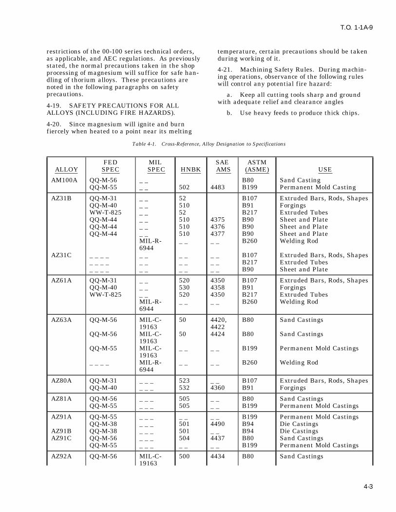
T.O. 1-1A-9
restrictions of the 00-100 series technical orders, temperature, certain precautions should be takenas applicable, and AEC regulations. As previously during working of it.stated, the normal precautions taken in the shop 4-21. Machining Safety Rules. During machin-processing of magnesium will suffice for safe han- ing operations, observance of the following rulesdling of thorium alloys. These precautions are will control any potential f ire hazard:noted in the following paragraphs on safetyprecautions. a. Keep all cutting tools sharp and ground
with adequate relief and clearance angles4-19. SAFETY PRECAUTIONS FOR ALLALLOYS (INCLUDING FIRE HAZARDS). b. Use heavy feeds to produce thick chips.
4-20. Since magnesium will ignite and burnfiercely when heated to a point near its melting
Table 4-1. Cross-Reference, Alloy Designation to Specifications
FED MIL SAE ASTMALLOY SPEC SPEC HNBK AMS (ASME) USE
AM100A QQ-M-56 _ _ B80 Sand CastingQQ-M-55 _ _ 502 4483 B199 Permanent Mold Casting
AZ31B QQ-M-31 _ _ 52 B107 Extruded Bars, Rods, ShapesQQ-M-40 _ _ 510 B91 ForgingsWW-T-825 _ _ 52 B217 Extruded TubesQQ-M-44 _ _ 510 4375 B90 Sheet and PlateQQ-M-44 _ _ 510 4376 B90 Sheet and PlateQQ-M-44 _ _ 510 4377 B90 Sheet and Plate
MIL-R- _ _ _ _ B260 Welding Rod6944
AZ31C _ _ _ _ _ _ _ _ _ _ B107 Extruded Bars, Rods, Shapes_ _ _ _ _ _ _ _ _ _ B217 Extruded Tubes_ _ _ _ _ _ _ _ _ _ B90 Sheet and Plate
AZ61A QQ-M-31 _ _ 520 4350 B107 Extruded Bars, Rods, ShapesQQ-M-40 _ _ 530 4358 B91 ForgingsWW-T-825 _ _ 520 4350 B217 Extruded Tubes
MIL-R- _ _ _ _ B260 Welding Rod6944
AZ63A QQ-M-56 MIL-C- 50 4420, B80 Sand Castings19163 4422
QQ-M-56 MIL-C- 50 4424 B80 Sand Castings19163
QQ-M-55 MIL-C- _ _ _ _ B199 Permanent Mold Castings19163
_ _ _ _ MIL-R- _ _ _ _ B260 Welding Rod6944
AZ80A QQ-M-31 _ _ _ 523 _ _ B107 Extruded Bars, Rods, ShapesQQ-M-40 _ _ _ 532 4360 B91 Forgings
AZ81A QQ-M-56 _ _ _ 505 _ _ B80 Sand CastingsQQ-M-55 _ _ _ 505 _ _ B199 Permanent Mold Castings
AZ91A QQ-M-55 _ _ _ _ _ _ _ B199 Permanent Mold CastingsQQ-M-38 _ _ _ 501 4490 B94 Die Castings
AZ91B QQ-M-38 _ _ _ 501 _ _ B94 Die CastingsAZ91C QQ-M-56 _ _ _ 504 4437 B80 Sand Castings
QQ-M-55 _ _ _ _ _ _ _ B199 Permanent Mold Castings
AZ92A QQ-M-56 MIL-C- 500 4434 B80 Sand Castings19163
4-3
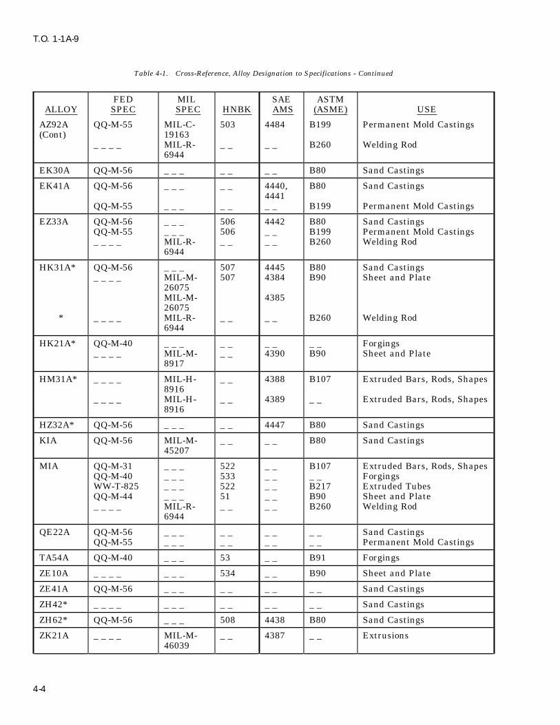
T.O. 1-1A-9
Table 4-1. Cross-Reference, Alloy Designation to Specifications - Continued
FED MIL SAE ASTMALLOY SPEC SPEC HNBK AMS (ASME) USE
AZ92A QQ-M-55 MIL-C- 503 4484 B199 Permanent Mold Castings(Cont) 19163
_ _ _ _ MIL-R- _ _ _ _ B260 Welding Rod6944
EK30A QQ-M-56 _ _ _ _ _ _ _ B80 Sand Castings
EK41A QQ-M-56 _ _ _ _ _ 4440, B80 Sand Castings4441
QQ-M-55 _ _ _ _ _ _ _ B199 Permanent Mold Castings
EZ33A QQ-M-56 _ _ _ 506 4442 B80 Sand CastingsQQ-M-55 _ _ _ 506 _ _ B199 Permanent Mold Castings_ _ _ _ MIL-R- _ _ _ _ B260 Welding Rod
6944
HK31A* QQ-M-56 _ _ _ 507 4445 B80 Sand Castings_ _ _ _ MIL-M- 507 4384 B90 Sheet and Plate
26075MIL-M- 438526075
* _ _ _ _ MIL-R- _ _ _ _ B260 Welding Rod6944
HK21A* QQ-M-40 _ _ _ _ _ _ _ _ _ Forgings_ _ _ _ MIL-M- _ _ 4390 B90 Sheet and Plate
8917
HM31A* _ _ _ _ MIL-H- _ _ 4388 B107 Extruded Bars, Rods, Shapes8916
_ _ _ _ MIL-H- _ _ 4389 _ _ Extruded Bars, Rods, Shapes8916
HZ32A* QQ-M-56 _ _ _ _ _ 4447 B80 Sand Castings
KIA QQ-M-56 MIL-M- _ _ _ _ B80 Sand Castings45207
MIA QQ-M-31 _ _ _ 522 _ _ B107 Extruded Bars, Rods, ShapesQQ-M-40 _ _ _ 533 _ _ _ _ ForgingsWW-T-825 _ _ _ 522 _ _ B217 Extruded TubesQQ-M-44 _ _ _ 51 _ _ B90 Sheet and Plate_ _ _ _ MIL-R- _ _ _ _ B260 Welding Rod
6944
QE22A QQ-M-56 _ _ _ _ _ _ _ _ _ Sand CastingsQQ-M-55 _ _ _ _ _ _ _ _ _ Permanent Mold Castings
TA54A QQ-M-40 _ _ _ 53 _ _ B91 Forgings
ZE10A _ _ _ _ _ _ _ 534 _ _ B90 Sheet and Plate
ZE41A QQ-M-56 _ _ _ _ _ _ _ _ _ Sand Castings
ZH42* _ _ _ _ _ _ _ _ _ _ _ _ _ Sand Castings
ZH62* QQ-M-56 _ _ _ 508 4438 B80 Sand Castings
ZK21A _ _ _ _ MIL-M- _ _ 4387 _ _ Extrusions46039
4-4

T.O. 1-1A-9
Table 4-1. Cross-Reference, Alloy Designation to Specifications - Continued
FED MIL SAE ASTMALLOY SPEC SPEC HNBK AMS (ASME) USE
ZK51A QQ-M-56 _ _ _ 509 4443 B80 Sand CastingsZK60A QQ-M-31 _ _ _ 524 4352 B107 Extruded Bars, Rods, Shapes
QQ-M-40 _ _ _ _ _ 4362 B91 ForgingsWW-T-825 _ _ _ 524 4352 B217 Extruded Tubes
ZK60B _ _ _ _ MIL-M- _ _ _ _ _ _ Extruded Bars, Rods, Shapes26696
ZK61A QQ-M-56 _ _ _ 513 4444 B80 Sand Castings
*These alloys contain radioactive thorium element. See paragraph 4-15 for precautionary instructions.
MISC SPECIFICATION
MIL-M-3171 Magnesium alloy, processes for corrosion protection of
SAE-AMS-M-6857 Magnesium alloy castings, heat treatment of
Change 4 4-5

T.O. 1-1A-9
Table 4-2. Alloy Designation Cross-Reference
FORMERNEW FORMER AMERICAN FORMER * NEW
DESIGNATOR DOW REVERE MAGNESIUM MILITARY FEDERAL USE
AZ63A H AM265 _ _ _ _ QQ-M-56 Castings, Sand
MIA M AM3S AN-M-26 QQ-M-31 Extruded Bars, Rods, Shapes
MIB M AM403 AN-M-30 QQ-M-56 Castings, Sand
MIA M AM3S AN-T-73 WW-T-825 Extruded Tube
MIA M AM3S AN-M-22 QQ-M-40 Forgings
MIA M AM3S AN-M-30 QQ-M-44 Sheet
A292A C AM260 _ _ _ _ QQ-M-56 Castings, Sand
AZ92A C AM260 _ _ _ _ QQ-M-55 Castings, Perm Mold
AM100A G AM240 _ _ _ _ QQ-M-55 Castings, Perm Mold
AZ91A R AM263 AN-M-16 QQ-M-38 Castings, Die
AZ31B FS-1 AM52S AN-M-27 QQ-M-31 Extruded Bar, Rod, Shape
AZ31B FS-1 AM52S AN-T-72 WW-T-825 Extruded Tube
AZ31B FS-1 AM52S _ _ _ _ _ _ _ _ Forgings
AZ31B FS-1 AM52S AN-M-29 QQ-M-44 Sheet
AZ61A J-1 AMC57S AN-M-24 QQ-M-31 Extruded Bar, Rod, Shape
AZ61A J-1 AMC57S AN-T-71 WW-T-825 Extruded Tubes
AZ61A J-1 AMC57S AN-M-20 QQ-M-40 Forgings
AZ80A 0-1 AMC58S AN-M-25 QQ-M-31 Extruded Bar, Rod, Shape
AZ80A 0-1 AMC58S AN-M-21 QQ-M-40 Forgings
ZK60A _ _ AMA76S _ _ _ _ QQ-M-31 Extruded Bar, Rod, Shape
EX41A _ _ AMA130 _ _ _ _ _ _ _ _ Castings, Perm Mold
EZ33A _ _ AMA131 _ _ _ _ _ _ _ _ Castings, Perm Mold
TA54A _ _ AM65S _ _ _ _ QQ-M-40 Forgings
NOTES: *These ‘‘AN’’ Specifications have been superseded by the listed Federal Specifications.
4-6
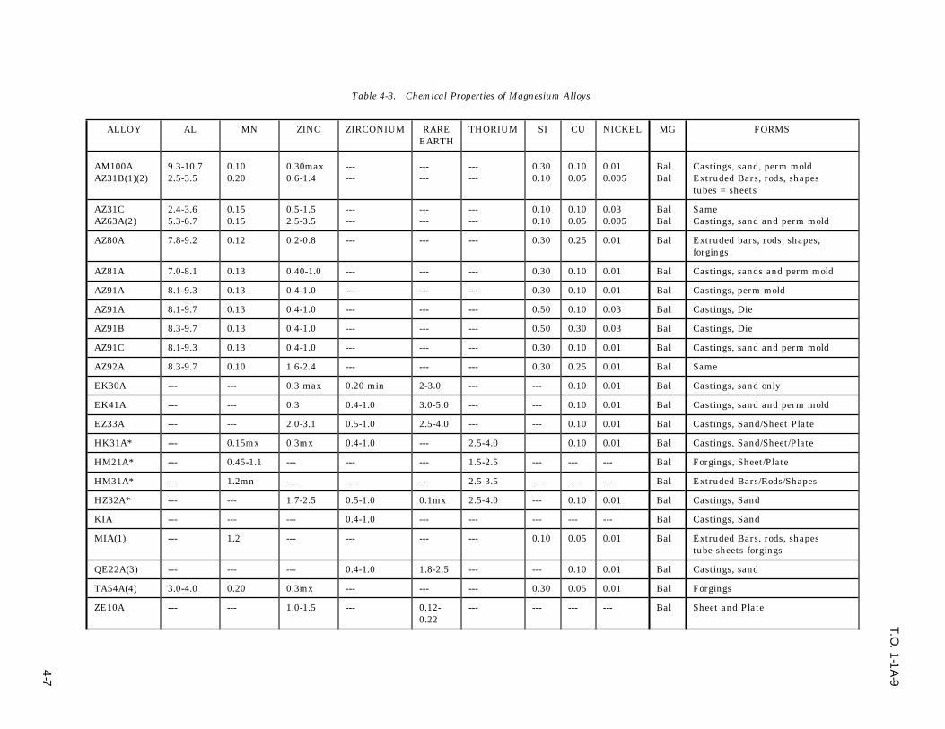
T.O. 1
-1A
-9
4-7
Table 4-3. Chemical Properties of Magnesium Alloys
ALLOY AL MN ZINC ZIRCONIUM RARE THORIUM SI CU NICKEL MG FORMSEARTH
AM100A 9.3-10.7 0.10 0.30max --- --- --- 0.30 0.10 0.01 Bal Castings, sand, perm moldAZ31B(1)(2) 2.5-3.5 0.20 0.6-1.4 --- --- --- 0.10 0.05 0.005 Bal Extruded Bars, rods, shapes
tubes = sheets
AZ31C 2.4-3.6 0.15 0.5-1.5 --- --- --- 0.10 0.10 0.03 Bal SameAZ63A(2) 5.3-6.7 0.15 2.5-3.5 --- --- --- 0.10 0.05 0.005 Bal Castings, sand and perm mold
AZ80A 7.8-9.2 0.12 0.2-0.8 --- --- --- 0.30 0.25 0.01 Bal Extruded bars, rods, shapes,forgings
AZ81A 7.0-8.1 0.13 0.40-1.0 --- --- --- 0.30 0.10 0.01 Bal Castings, sands and perm mold
AZ91A 8.1-9.3 0.13 0.4-1.0 --- --- --- 0.30 0.10 0.01 Bal Castings, perm mold
AZ91A 8.1-9.7 0.13 0.4-1.0 --- --- --- 0.50 0.10 0.03 Bal Castings, Die
AZ91B 8.3-9.7 0.13 0.4-1.0 --- --- --- 0.50 0.30 0.03 Bal Castings, Die
AZ91C 8.1-9.3 0.13 0.4-1.0 --- --- --- 0.30 0.10 0.01 Bal Castings, sand and perm mold
AZ92A 8.3-9.7 0.10 1.6-2.4 --- --- --- 0.30 0.25 0.01 Bal Same
EK30A --- --- 0.3 max 0.20 min 2-3.0 --- --- 0.10 0.01 Bal Castings, sand only
EK41A --- --- 0.3 0.4-1.0 3.0-5.0 --- --- 0.10 0.01 Bal Castings, sand and perm mold
EZ33A --- --- 2.0-3.1 0.5-1.0 2.5-4.0 --- --- 0.10 0.01 Bal Castings, Sand/Sheet Plate
HK31A* --- 0.15mx 0.3mx 0.4-1.0 --- 2.5-4.0 0.10 0.01 Bal Castings, Sand/Sheet/Plate
HM21A* --- 0.45-1.1 --- --- --- 1.5-2.5 --- --- --- Bal Forgings, Sheet/Plate
HM31A* --- 1.2mn --- --- --- 2.5-3.5 --- --- --- Bal Extruded Bars/Rods/Shapes
HZ32A* --- --- 1.7-2.5 0.5-1.0 0.1mx 2.5-4.0 --- 0.10 0.01 Bal Castings, Sand
KIA --- --- --- 0.4-1.0 --- --- --- --- --- Bal Castings, Sand
MIA(1) --- 1.2 --- --- --- --- 0.10 0.05 0.01 Bal Extruded Bars, rods, shapestube-sheets-forgings
QE22A(3) --- --- --- 0.4-1.0 1.8-2.5 --- --- 0.10 0.01 Bal Castings, sand
TA54A(4) 3.0-4.0 0.20 0.3mx --- --- --- 0.30 0.05 0.01 Bal Forgings
ZE10A --- --- 1.0-1.5 --- 0.12- --- --- --- --- Bal Sheet and Plate0.22

T.O. 1
-1A
-9
4-8 Table 4-3. Chemical Properties of Magnesium Alloys - Continued
ALLOY AL MN ZINC ZIRCONIUM RARE THORIUM SI CU NICKEL MG FORMSEARTH
ZE41A --- --- 4.25 0.5 1.25 --- --- --- --- Bal Castings, Sand
ZH42* --- --- 3.0-4.5 0.5 --- 1.5-2.5 --- --- --- Bal Castings, Sand
ZH62A* --- --- 5.2-6.2 0.5-1.0 --- 1.4-2.2 --- 0.10 0.01 Bal Castings, Sand
ZK20A --- --- 2.0-2.6 0.45mn --- --- --- --- --- Bal Extrusions
ZK51A --- --- 3.6-5.5 0.5-1.0 --- --- --- 0.10 0.01 Bal Castings, Sand
ZK60A --- --- 4.8-6.2 0.45 --- --- --- --- --- Ba1 Extruded Bars/Rods/ShapesTube-Forgings
ZK60B --- --- 4.8-6.8 0.45 --- --- --- 0.10 0.01 Bal Same
*NOTE: These alloys contain radioactive thorium. See paragraph 4-15(1) Calcium, AZ31B, 0.04---MIA, 0.4.0.14(2) Iron, AZ31B, 0.005---AZ61A, 0.005---AZ63A, 0.005.(3) Silver, QE22A, 2.5-3.0(4) Tin, TA54A, 4.6-6.0

T.O. 1
-1A
-9
4-9
Table 4-4. Mechanical Properties Magnesium Extrusions and Forgings at Room Temperature - Typical
MINALLOY DIEMN (DIA CROSS SEC- MIN TEN- MIN TEN MIN SHEAR& C0ND FORM THICKNESS: WALL TIONAL AREA SILE STR YLD STR ELONGA- STR HARDNESS
THKNESS - IN’S) (INCHES) (1000PSI) (1000PSI) tion (1000PSI) (BRINELL)(2″ %)
AZ31B-F Bars, Rods, 0.249 and under All areas 35 21 7 17 --and shapes 0.250-1.499 All areas 35 22 7 17 49
AZ31C-F 0.500-2.499 All areas 34 22 7 17 --2.500-4.999 All areas 32 20 7 -- --
Hollow All dimensions All areas 32 16 8 17 49shapes
AZ61A-F Bars, rods, 0.249 and under All areas 38 21 8 -- --shapes 0.250-1.499 All areas 39 24 9 18 60
0.250-4.999 All areas 40 22 7 -- --Hollow All dimensions All areas 36 16 7 18 60shapes
AZ80A-F Bars, Rods, 0.249 and under All areas 43 28 9 19 60shapes 0.250-1.499 All areas 43 28 8 19 60
1.500-2.499 All areas 43 28 6 19 602.500-4.999 All areas 42 27 4 -- 60
T-5 Same 0.249 and under All areas 47 30 4 -- 820.250-2.499 All areas 48 33 4 21 822.500-4.999 All areas 45 30 2 -- 82
HM31A-T5* Bars, rods, Not applicable Under 4.000 37 26 4shapes
MIA-F Bars, rods, 0.249 and under All areas 30 not req 2 -- 44shapes 0.250-1.499 All areas 32 not req 3 15 44
1.500-2.499 All areas 32 not req 2 15 442.500-4.999 All areas 29 not req 2 -- 44
Hollow All dimensions All areas 28 not req 2 15 44shapes
ZK60A-F Bars, rods, All dimensions 4.999 and under 43 31 5 22 75shapes 5.000-29.999 43 31 4 22 75Hollow All dimensions All areas 40 28 5 -- --shapes
T5 Bars, rods, All dimensions 4.999 and under 45 36 4 22 82shapesHollow All dimensions All areas 46 38 4 22 82shapes
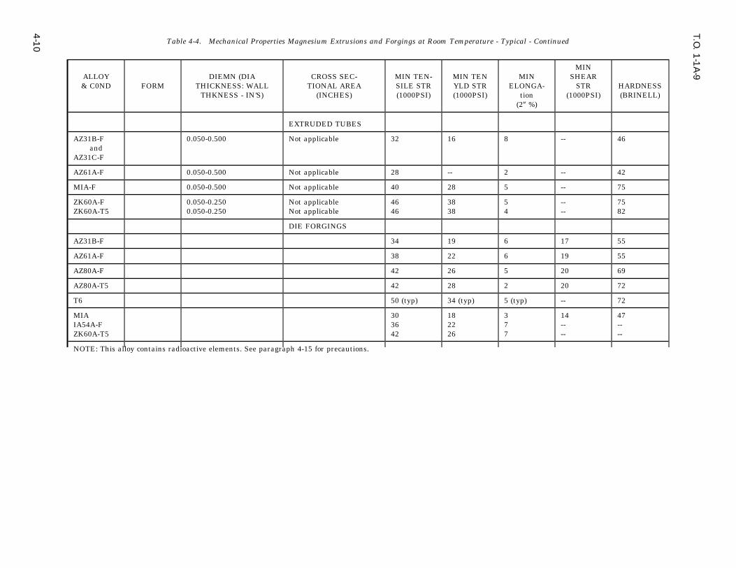
T.O. 1
-1A
-9
4-1
0 Table 4-4. Mechanical Properties Magnesium Extrusions and Forgings at Room Temperature - Typical - Continued
MINALLOY DIEMN (DIA CROSS SEC- MIN TEN- MIN TEN MIN SHEAR& C0ND FORM THICKNESS: WALL TIONAL AREA SILE STR YLD STR ELONGA- STR HARDNESS
THKNESS - IN’S) (INCHES) (1000PSI) (1000PSI) tion (1000PSI) (BRINELL)(2″ %)
EXTRUDED TUBES
AZ31B-F 0.050-0.500 Not applicable 32 16 8 -- 46and
AZ31C-F
AZ61A-F 0.050-0.500 Not applicable 28 -- 2 -- 42
MIA-F 0.050-0.500 Not applicable 40 28 5 -- 75
ZK60A-F 0.050-0.250 Not applicable 46 38 5 -- 75ZK60A-T5 0.050-0.250 Not applicable 46 38 4 -- 82
DIE FORGINGS
AZ31B-F 34 19 6 17 55
AZ61A-F 38 22 6 19 55
AZ80A-F 42 26 5 20 69
AZ80A-T5 42 28 2 20 72
T6 50 (typ) 34 (typ) 5 (typ) -- 72
MIA 30 18 3 14 47IA54A-F 36 22 7 -- --ZK60A-T5 42 26 7 -- --
NOTE: This alloy contains radioactive elements. See paragraph 4-15 for precautions.

T.O. 1
-1A
-9
4-1
1
Table 4-5. Mechanical Properties Magnesium Alloy Sheet and Plate at Room Temperature - Typical
MINIMUM** MINIMUM** MIN ELON- MINIMUMDIMENSION TENSILE TENSILE GATION SHEAR
ALLOY & THICKNESS STRENGTH YIELD STR (2″--%) STRENGTH HARDNESSCOND (INCHES) (1000PSI) (1000PSI) (1000PSI) (BRINELL) USE
AZ31B-F All gauges 35 (typical) 19 (typical) 12 (typical) -- -- Tooling PlateAZ31B-H10 0.251-2.000 30 12 10 -- -- Standard Plate
-H11 0.016-0.250 32 12 12 -- -- Standard Plate andSheet
-H23 0.016-0.064 39 25 4 -- -- Standard Sheet0.065-0.064 39 25 4 -- -- and Plate
-H24 0.016-0.063 39 29 4 18 73 Spec Sheet and Plate0.065-0.250 39 29 4 18 73 Same0.251-0.500 37 24 10 -- -- Same0.501-1.000 37 22 10 -- -- Same
-H26 0.501-0.750 37 25 8 -- -- Spec Sheet and Plate0.751-1.000 37 23 8 -- --1.001-1.500 35 22 8 -- --
-0 0.016-0.060 32 18 12 17 56 Spec Sheet and Plate0.061-0.250 32 15 12 17 56 Same0.251-0.500 32 15 12 -- -- Same0.501-2.000 30 15 10 -- -- Same
AZ31C-F All gauges 32 15 8 -- 52 Tread plate
HK31A-0* 0.016-0.250 30 16 12 -- -- Sheet0.251-0.500 30 16 12 -- -- Sheet0.501-1.000 30 15 12 -- -- Sheet1.001-3.000 29 14 12 -- -- Sheet
-H24* 0.016-0.125 34 26 4 21 (typ) 57 Sheet0.126-0.250 31 22 4 21 (typ) 57 Sheet0.251-1.000 34 25 4 20 (typ) -- Sheet1.001-3.000 33 25 4 20 (typ) -- Sheet
HM21A-T8 0.016-0.250 31 18 4 Sheet and Plate0.251-0.500 32 21 6 Sheet and Plate0.501-1.000 30 19 6 Sheet and Plate1.001-2.000 29 18 6 Sheet and Plate
MIA-O All Gauges 33 (typ) 18 (typ) 17 (typ) 17 (typ) 48 Sheet and PlateH All gauges 35 (typ) 26 (typ) 7 (typ) 7 (typ) 54
ZE10-0 0.016-0.060 30 18 15 Sheet and Plate0.061-0.250 30 15 150.251-0.500 29 12 12
H24 0.016-0.125 36 25 4 Sheet and Plate0.126-0.188 34 22 40.189-0.250 31 20 4
* Contains radioactive thorium element. See paragraph 4-19 for precautionary data.
** Values given are all minimum unless otherwise noted beside value.

T.O. 1-1A-9
Table 4-6. Mechanical Properties of Magnesium Alloy Castings at Room Temperatures
ALLOY & COND TENSILE TENSILE TYPICALSTRENGTH STRENGTH ELONGATION SHEAR
YIELD(1000 PSI) (1000 PSI) IN 2″--% STRENGTH HARDNESS
TYPE MIN TYPE MIN TYPE MIN (1000 PSI) (Brinell)
AM100A-F 22 20 12 10 2 -- 18 54-T4 40 34 13 10 10 6 20 52-T6 40 34 16 15 4 2 21 69-T61 40 34 22 17 1 -- 21 69
AZ63A-F 29 24 14 10 6 4 16 50-T4 40 34 14 10 12 7 17 55-T5 30 24 16 10 4 2 17 55-T6 40 34 19 16 5 3 19 73
AZ81A-T4 40 34 14 10 12 7 17 55
AZ91C-F 24 18 14 10 2.5 -- 16 52-T4 40 34 14 10 11 7 17 55-T5 23 23 12 12 2 -- -- ---T6 40 34 19 16 5 3 19 73
AZ92A-F 24 20 14 10 2 1 16 65-T4 40 34 14 10 10 6 17 63-T5 26 20 17 11 1 -- 16 80-T6 40 34 21 18 2 1 20 84
EK30A-T6 23 20 16 14 3 2 18 45
EK41A-T5 23 20 16 14 1 -- 18.7 45-T6 25 22 18 16 3 1 19.4 50
EZ33A-T5 23 20 15 14 3 2 19.8 50
HK31A-T6* 30 27 15 13 8 4 21 55
HZ32A-T5* 29 27 14 13 7 4 20 57
KIA-F 24 24 6 6 14 14 -- --
QE22A-T6 35 35 25 25 2 2 -- --
ZE41A-T5 28 28 19 19 2.5 2.5 23 62
ZH42-T51* 32.5 -- 21.6 -- 4.5 -- -- --
ZH42-T4* 33.6 35 -- -- 12 -- -- --
ZH62A-T5 35.0 35 22 22 4 5 24 70
ZK51A-T5 40 34 24 20 8 5 22 65
ZK61A-T6 39 39 26 26 5 5 26 68
DIE CASTINGS
AZ91A-F 33 -- 22 -- 3 -- 20 67AZ91B-F 33 -- 22 -- 3 -- 20 67
NOTE: *This alloy contains radioactive thorium element. See paragraph 4-19 precautionary instruc-tions.
4-12

T.O. 1-1A-9
Table 4-7. Physical Properties Magnesium Alloy @68oF
ALLOY & COND SPECIFIC DENSITY MELTING ELECTRICALGRAVITY LBS/CU in RANGEoF CONDUCTIVITY
(IACS)
AM100A-F 1.81 0.065 867-1101 11.5-T4 1.81 0.065 867-1101 9.9-T6 1.81 0.065 867-1101 12.3
AZ31B and AZ31C 1.77 0.064 1116-1169 18.5AZ61A 1.80 0.065 977-1145 11.6AZ63A-F 1.82 0.066 850-1130 15.0
-T4 1.82 0.066 850-1130 12.3-T6 1.82 0.066 850-1130 13.8
AZ80A 1.80 0.065 914-1130 10.6AZ81A 1.81 0.065 914-1132 12.0AZ91A-AZ91B 1.81 0.065 875-1105 10.1AZ91C-F 1.81 0.065 875-1105 11.5
-T4 1.81 0.065 875-1105 9.9-T6 1.81 0.065 875-1105 11.2
AZ92A-AC 1.83 0.066 830-1100 12.3-T4 1.83 0.066 830-1100 10.5-T6 1.83 0.066 830-1100 12.3
EK30A 1.79 0.065 1100-1184 27.0EK41A-T5 1.81 0.065 1193 24.0
-T6 1.81 0.065 1193 26.0EZ33A 1.83 0.066 1010-1189 25.0HK31A-T6 1.79 0.065 1092-1204 22.0HM21A 1.77 0.064 1100-1195HM-31A-F 1.80 0.065 1121-1202 26.0HM32A 1.83 0.066 1026-1198 26.5MI-A 1.76 0.064 1200 34.5TA54A 1.87 0.067 -- --ZE10A 1.76 0.063 1100-1200 --ZH42 1.86 0.067 1180 23.9ZH62A 1.86 0.067 1180 26.5ZK21A 1.80 0.645 -- --ZK51A 1.81 0.066 1020-1185 28.0ZK60A-F 1.83 0.066 968-1175 29.0
-T5 1.83 0.066 968-1175 30.0ZK60B 1.83 0.066 968-1175 31.0ZK61A 1.80 0.065 1145 --
NOTE: Percentage conductivity of annealed copper at 68oF (international annealed copper standard).
c. Machine the metal dry whenever possible, Machinists should not wear textured or fuzzyavoiding fine feeds and keeping speeds below 500 - clothing and chips and sawdust should not be700 surface feet per minute during turning and allowed to accumulate in cuffs or pockets.boring. If a coolant is definitely required use amineral oil. f. Do not permit tools to rub on the work
after a cut has been made.d. Keep work areas clean.
e. Store magnesium chips in clean, plainly g. Keep an adequate supply of a recom-labeled, covered, non-combustible containers where mended magnesium fire extinguisher within reachthey will remain dry. Do not allow chips to accu- of the operators. If chips should become ignited,mulate on machines or operator’s clothing. extinguish them as follows:
4-13
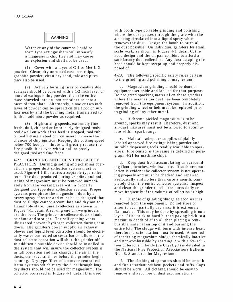
T.O. 1-1A-9
with booth type portable grinding and polishingwhere the dust passes through the grate with the
WARNING air being circulated into a liquid spray whichremoves the dust. Design the booth to catch allthe dust possible. On individual grinders for smallWater or any of the common liquid orscale work, as shown in Figure 4-1, detail C, thefoam type extinguishers will intensifyhood design and the oil pan combine to afford aa magnesium chip fire and may causesatisfactory dust collection. Any dust escaping thean explosion and shall not be used.hood should be kept swept up and properly dis-
(1) Cover with a layer of G-1 or Met-L-X posed of.powder. Clean, dry unrusted cast iron chips,
4-23. The following specific safety rules pertaingraphite powder, clean dry sand, talc and pitchto the grinding and polishing of magnesium:may also be used.
a. Magnesium grinding should be done on(2) Actively burning fires on combustibleequipment set aside and labeled for that purpose.surfaces should be covered with a 1/2 inch layer orDo not grind sparking material on these grindersmore of extinguishing powder; then the entireunless the magnesium dust has been completelymass shoveled into an iron container or onto aremoved from the equipment system. In addition,piece of iron plate. Alternately, a one or two inchthe grinding wheel or belt must be replaced priorlayer of powder can be spread on the f loor or sur-to grinding of any other metal.face nearby and the burning metal transferred to
it, then add more powder as required.b. If chrome pickled magnesium is to be
ground, sparks may result. Therefore, dust and(3) High cutting speeds, extremely fineair-dust mixtures must not be allowed to accumu-feeds, dull, chipped or improperly designed tools,late within spark range.tool dwell on work after feed is stopped, tool rub,
or tool hitting a steel or iron insert increase thec. Maintain adequate supplies of plainlychances of chip ignition. Keeping the cutting speed
labeled approved fire extinguishing powder andbelow 700 feet per minute will greatly reduce thesuitable dispensing tools readily available to oper-fire possibilities even with a dull or poorlyators. Fire control is the same as detailed in para-designed tool and fine feeds.graph 4-21 for machine chips.
4-22. GRINDING AND POLISHING SAFETYd. Keep dust from accumulating on surround-PRACTICES. During grinding and polishing oper-
ing f loors, benches, windows, etc. If such accumu-ations a proper dust collection system must belation is evident the collector system is not operat-used. Figure 4-1 illustrates acceptable type collec-ing properly and must be checked and repaired.tors. The dust produced during grinding and pol-Periodically and no less than once a month, com-ishing of magnesium must be removed immedi-pletely clean the entire collector systems. Inspectately from the working area with a properlyand clean the grinder to collector ducts daily ordesigned wet type dust collection system. Propermove frequently if the volume of collection is high.systems precipitate the magnesium dust by a
heavy spray of water and must be so designed that e. Dispose of grinding sludge as soon as it isdust or sludge cannot accumulate and dry out to a removed from the equipment. Do not store orf lammable state. Small collectors as shown in allow to even partially dry since it is extremelyFigure 4-1, detail A serving one or two grinders f lammable. This may be done by spreading it on aare the best. The grinder-to-collector ducts should layer of f ire brick or hard burned paving brick to abe short and straight. The self opening vents maximum depth of 3″ to 4″, then placing a com-illustrated prevent hydrogen collection during shut bustible material on top of it and burning thedown. The grinder’s power supply, air exhaust entire lot. The sludge will burn with intense heat,blower and liquid level controller should be electri- therefore, a safe location must be used. A methodcally water connected so cessation or failure of the of rendering magnesium sludge chemically inactivedust collector operation will shut the grinder off. and non-combustible by reacting it with a 5% solu-In addition a suitable devise should be installed in tion of ferrous chloride (Fe C122H2O) is detailed inthe system that will insure the collector system is the National Fire Protection Association’s Bulletinin full operation and has changed the air in the No. 48, Standards for Magnesium.ducts, etc., several times before the grinder beginsrunning. Dry type filter collectors or central col- f. The clothing of operators should be smoothlector systems which carry the dust through long and fire retardant without pockets and cuffs. Capsdry ducts should not be used for magnesium. The should be worn. All clothing should be easy tocollector portrayed in Figure 4-1, detail B is used remove and kept free of dust accumulations.
4-14

T.O. 1-1A-9
4-24. Deleted. covered with the powder, the furnace load shouldbe allowed to cool with the door open. For the4-25. HEAT TREATING SAFETY PRACTICES. handling of large quantities of G-1 powder, pumpsHeat treating of magnesium alloys requires the have been constructed which can throw 75-100 lbs/exercising of certain definite rules, if safe and good minute onto the fire through a 30 foot hose andquality workmanship is to result. The following nozzle.rules should be closely followed:
(2) Boron Trif luoride (BF3) Gas Method.a. Use furnace equipment having two sets oftemperature controls, operating independently ofeach other.
WARNINGb. Standardize checking procedures and
adjustments of all equipment and of operatingBoron trif luoride vapor or gas is toxiccycles.in the proportion of more than 1 part
c. Load the furnace with castings of one iden- per million by volume of air whentical alloy only. Insure the castings are clean. exposures are prolonged or frequently
repeated. Five parts per million byd. Use SO2 (Sulfur Dioxide) atmosphere to volume of air or more are usually pre-control oxidation. sent in visible clouds of materiale. Use the recommended time and tempera- resulting from the release of the gas
ture operating ranges at all times. to atmosphere. Therefore, personnelmust not enter such clouds or anyf. Provide approved fire extinguishing area where there is reason to believeequipment. the safe level is exceeded unless wear-ing a gas mask with an acid gas can-ister containing a dust f iller. Analy-
WARNING sis of atmosphere in the worker’sbreathing zone will be accomplishedto assure personnel safety.Water and other extinguishers for
Class A, B, and C fires shall not be This is an effective gaseous means of extinguish-used. ing magnesium fires in heat treating furnaces.
The gas is introduced into the furnace from a stor-4-26. If a f ire should occur for any reason, asage cylinder through an entry port preferablyevidenced by excessive furnace temperature andlocated near f loor level. Connect the gas feed lineomission of a light colored smoke, proceed asto this port, open the feed line valve to providefollows:about 2 lbs/minute (depending on furnace size and
a. Shut off all power, fuel and SO2 feed lines number of gas cylinders) and maintain gas f lowto the furnace. until furnace temperature drops to 700oF indicat-
ing the fire is out. The furnace door should beb. Notify f ire marshal control crew at once.kept closed during this action and until a definite
c. Begin fire extinguishing procedures using temperature drop below 700oF is evident. Run-one of the following methods: ning the furnace circulating fans for about 1 min-
ute after the gas is f irst introduced will assist in(1) G-1 Powder Method. gas dispersal, then shut the fan off. The gas cylin-Where it can be safely done, a small f ire should be der used should be fitted with a Monel needleremoved from the furnace, dumped into an iron valve and a ‘‘tee’’ for attaching a 0-160 psi pres-container and then extinguished by covering with sure gauge. A suitable gas transfer system uses aG-1 powder which is a graphite base powder of the 5/16″ f lexible bronze hose to carry the gas to thePyrene CO2 Company. Metal Fyr Powder of the furnace where it enters through a 1/4″ steel pipeFyr Fyter Company is the same material. In large entry port. Using 10 feet of hose and feed of pipe,furnaces or with fires of high intensity, the powder a gauge pressure of 15-30 psi will deliver 1-2 lbs ofcan be applied to the burning parts with a shovel BF3 per minute. The cylinders may be perma-(assuming the furnace door can be opened safely). nently connected or brought to the furnace, whenPaper bags filled with the powder can be used if needed, on a suitable dolly. This gas does notthe fire is so located that such bags can be thrown require heating in order to f low. The cylindersin effectively. Remove parts not burning with long should be weight checked for contents every 6handled hooks. After all burning parts have been months.
Change 1 4-15
T.O. 1-1A-9
(3) Boron Trichloride (BCL3) Gaseous iridescent coating forms the alloy contains alumi-Method. This material has been successfully used num. The solution is made in the proportions ofto extinguish magnesium heat treat furnace fires. 24 ounces sodium dichromate and 24 f luid ouncesHowever, there are several factors involved with concentrated nitric acid to enough water to makeits use which makes it less preferred than boron one gallon. Prior to the test the metal should betrif luoride, these include: ten times more concen- thoroughly cleaned down to the base metal, if nec-tration than the 0.04% of boron trif luoride, the gas essary, by grinding or f iling a clean area on themust be heated to f low freely; it is more expensive surface.than trif luoride; the liquid is corrosive and the 4-29. HEAT TREATING MAGNESIUM ALLOYSfumes irritating with a health hazard similar to - GENERAL.hydrochloric acid fumes. Workmen should notoccupy areas where noticeable vapors are present NOTEunless wearing a gas mask with an acid gas canis- . SAE-AMS-M-6857, Heat Treatment ofter containing a dust f ilter. If this agent must be
Magnesium Alloy Castings, will beused, the liquid containing cylinders should bethe control for heat treatment of mag-heated with infrared lights to provide the heatnesium alloy castings used on aero-necessary to insure adequate gas f low. The cylin-space equipment. For completeder outlet should be fitted with a special valve anddescription of magnesium alloy cast-gauge to control gas f low. Flexible 5/8″ ID neo-ings heat treat requirements, refer toprene hose may be used to connect the cylinder tolatest issue of SAE-AMS-M-6857.a steel pipe for insertion into the furnace port.
Otherwise its use in extinguishing a furnace fire is . Additional Heat Treatment informa-similar to the procedures for boron trif luoride. tion is discussed in Section IX.4-27. IDENTIFICATION OF ALLOY. 4-30. PRECAUTIONS DURING HEATING. Of
first importance in the heat processing of these4-28. Positive identification of an alloy, from aalloys is a clear understanding of the characteris-constituency standpoint, can only be determinedtics of the metal relative to heat. Pure magnesiumby laboratory analysis. However, whether a lightwill melt at approximately 1202oF. The alloysmetal is magnesium or not can be generally deter-melting points range from 830oF to 1204oF,mined by a simple test consisting of placing theapproximately, according to their element constitu-test metal in contact with an 0.5% solution of sil-ency. Therefore, during any heating of alloy items,ver nitrate, and observing the reaction for 1 min-specified temperature maximums must be closelyute. The solution is made by dissolving 0.5g. ofadhered to, particularly during solution heat treat-silver nitrate in 100 ml. of water. Formation of aing. The metal is easily burned and overheatingblack deposit of metallic silver on the metal indi-will also cause formation of molten pools within it,cates magnesium or high-magnesium alloy. Theneither condition resulting in ruining of the metal.immerse the metal in a chrome pickle chemicalCertain alloys such as AZ63A Type 1, or AZ92Asolution, Type I Specification MIL-M-3171 (Com-Type 1, are subject to eutectic melting of some ofmercially known as DOW No. 1). The solutionits elements if heated too rapidly. They must beshould be freshly prepared and the test operatorbrought up to heat treating temperature slowlyfamiliar with the colors of chemical treatment. Ifenough to prevent this. In the case of these twothe metal assumes a very bright brassy coating, it
indicates it is aluminum free alloy. If a greyish
4-16 Change 4

T.O. 1-1A-9
examples, no less than two hours should be con- capability of maintaining the minimum and maxi-mum temperatures required for the various treat-sumed in bringing them from 640oF to treatingments it will be used for. A minimum of 9 testtemperature.locations within the furnace load area should be
4-31. An additional and no less important char- checked. One in each corner, one in the centeracteristic of the metal relative to heat treatment, and one for each 25 cubic feet of furnace volumeis that it is subject to excessive surface oxidation up to the maximum of 400 cubic feet. A monthlyat 750oF and higher temperatures. In an oxidizing survey should be made after the initial survey,atmosphere, this characteristic can result in igni- unless separate load thermocouples are employed,tion and fierce burning. To prevent such occur- to record actual metal temperatures. The monthlyrences, a protective atmosphere containing suffi- survey should consist of one test for a solutioncient sulphur dioxide, carbon dioxide or other heat treat temperature and one test for a precipi-satisfactory oxidation inhibitor shall be used when tation heat treat temperature, one for each 40
cubic feet of heat treating volume with a mini-heating to 750oF and over. When oxidation inhibi-mum, of 9 test locations required regardless of thetors are used, their concentration percentage involume. In addition, a periodic survey should bethe furnace atmosphere should be periodicallymade, using the test criteria of the initial survey.checked for correct amounts. The particularFor all surveys, the furnaces should be allowed torequirements for various alloys are detailed in par-heat to a point stabilization before taking anyagraph 4-46 in this section. These requirementsreadings. The temperature of all test locationsand those of other pertinent specifications andshould be determined at 5 to 10 minute intervalsinstructions should be consulted and strictlyafter insertion of the temperature sensing ele-adhered to in processing the metal. The safetyments in the furnace. The maximum temperaturemeasures defined in paragraph 4-1 must be rigidlyvariation of all elements shall not exceed 20oF andpracticed.shall not exceed the solution or precipitation heat
4-32. HEAT TREATING EQUIPMENT. treating range at any time after equilibrium isreached.
4-33. Furnaces used for solution heat treatment4-35. Furnace control temperature measuringshall be of the air chamber type with forced airinstruments shall not be used as test instrumentscirculation. Heating provisions can be gas, electri-during any survey. The thermocouple and sensingcity or oil. Their design must be such as to makeelements should be replaced periodically becauseimpossible, direct heating element radiation orof the in-service incurred effects of oxidation andf lame impingement on the articles being treated.deterioration.The furnaces shall be installed with the necessary
control, temperature measuring and recording 4-36. Pyrometers used with the automatic con-instrument equipment to assure complete and trol system to indicate, maintain and record theaccurate control. The temperature control shall be furnace temperatures, should preferably be of thecapable of maintaining a given temperature to potentiometer type.within ± 10o F at any point in the working zone,
4-37. Suitable jigs, f ixtures, trays, hangers,after the charge has been brought up to this tem-racks, ventilators and other equipment shall beperature. Each furnace used shall be equippedused in processing the articles.with a separate manual reset safety cut-out which
will turn off the heat source in the event of any 4-38. HEAT TREATMENT SOLUTION. Solu-malfunction or failure of the regular automatic tion for heat treating of magnesium alloyed arti-controls. The safety cut-outs shall be set as close cles is accomplished by heating at an elevatedas practicable above the maximum solution heat temperature in an air furnace for a specific lengthtreating temperature for the alloy being treated. of time (holding period); during which certainThis will be above the variation expected but shall alloying elements enter into uniform solid solution,not be more than 10oF above the maximum heat since the alloys tend to become plastic at high heattreat temperature of the alloy being processed. treat temperatures, it is mandatory that suitableThere shall also be protective devices to shut off support be provided for articles being processed tothe heat source in case of circulation air stoppage. prevent warping. Table 4-8 below lists the recom-These devices shall be interconnected with a man- mended soaking and holding time for solution heatual reset control. treating alloys. The holding periods given are for
castings up to 2 inches thick. Items thicker than 24-34. Upon initial furnace installation and after inches will require longer periods.any maintenance on the furnace or its equipmentwhich might affect its operational characteristics, 4-39. AZ92A (Type 2), AZ91C and QE22A sanda temperature survey shall be made to test its castings and AM100A permanent mold castings
4-17

T.O. 1-1A-9
may be charged into the furnace which is at the 4-41. Stabilization heat treating an alloyheat treating temperature. Since magnesium cast- increases its creep strength and retards growth atings are subject to excessive surface oxidation at service encountered elevated temperatures. Thetemperatures of 750oF and over, a protective same general procedure of heating to temperature,atmosphere containing sufficient sulphur dioxide, holding for a time and cooling to room tempera-carbon dioxide or other satisfactory oxidation ture is used as in the other two types, only theinhibitor shall be used when solution heat treating temperature and time elements are different.at 750oF and over. The whole casting must be When applied to a solution treat treated alloy, itheat treated, not just part of it. increases the alloy’s yield strength. Actually stabi-
lization treatment is a high temperature aging4-40. Precipitation heat treatment or artif icial treatment accomplished quickly rather thanaging of alloys is accomplished at temperature allowing an alloy to age naturally over a period oflower than those of the solution treatment. Sug- time.gested aging treatments for various alloys are ascited in Table 4-9.
Table 4-8. Solution Heat Treating Temperatures and Holding Times
TEMPERATUREALLOY RANGE TIME PERIOD(HRS) MAX TEMP oF
AM100A 790-800 16-24 810
AZ63A (Type 1) 720-730 (F to T4) 10-14 734
AZ63A (Type 2)* 720-740 (F to T4) 10-14 745
AZ81A 770-785 16-24 785
AZ91C 770-785 16-24 785
AZ92A (Type 1) 760-770 16-24 775
AZ92A (Type 2) 775-785 14-22 785
HK31A 1045-1055 2 1060
QE22A** 970-990 4-8 1000
ZK61A 925-935 2 935or
895-905 10 935
* Contains calcium.
** Quench in 150oF water bath within 30 seconds after opening of furnace.
4-42. Annealing of magnesium alloys is accom- 4-43. HEAT TREATING PROCEDURES. Plac-plished to relieve internal stresses, generally ing of articles to be treated in the furnace, (gener-resulting from forming operations; soften the ally referred to as charging the furnace), shouldmaterial for forming; improve the ductility; and/or not be done in a haphazard fashion. Individualrefine the grain structure. The alloy is heated to pieces should be racked or supported to preventthe proper temperature, soaked or held at that distorting without interfering with the free f low oftemperature for a specified time and cooled to the heated atmosphere around the article. Distor-room temperature. The desired effects are gained tion or warping can occur due to the semi-plasticby controlling the temperature, hold time and cool- qualities of the alloys at the furnace elevated tem-ing medium exposure. Avoid excessive time at peratures during solution heat treat. Distortion istemperature to prevent unwanted grain growth. not a particular problem during precipitation orConversely, no attempt should be made to shorten stabilization treatment or annealing. However, itthe time at temperature and over all annealing is good practice to handle magnesium alloy articlestime by increasing the temperature, since ele- with care at all times under elevated heat condi-ments of the alloy subject to melting points lower tions. In the case of complicated formed parts, itthen the alloy itself can go into solution. may be necessary to utilize a specially contoured
4-18

T.O. 1-1A-9
jig or f ixture to adequately protect the design con- a. AM100-A - Used in pressure tight sand endtour of the item at high temperatures. permanent mold castings with good combination of
tensile strength, yield strength and elongation.4-44. Cooling after treating is accomplished in Solution heat treat in 0.5% SO2 atmosphere 20either still or blast air, depending upon the alloy. hours at 790oF; cool in strong air blast. PartiallyThe one exception is alloy QE22A which is water artificial aging -12 hours at 325oF; cool in still air.quenched. The water should be at 150oF Completely artif icial age 5 hours at 450oF; cool intemperature. still air or oven. Aging increases basic yieldstrength and hardness and decreases toughness4-45. ALLOY GENERAL CHARACTERISTICand elongation.INFORMATION.
4-46. In the following paragraphs are brief sum-maries of the general characteristics of the variousalloys.
Table 4-9. Artificial Aging (Precipitation Treatment)
ALLOY & TEMPER AGING TREATMENT
AM100A-T6 5 hours at 450oF or 24 hours at 400oF
AM100A-T5* 5 hours at 450oF
AZ63A-T6 5 hours at 425oF or 5 hours at 450oF
AZ63A-T5* 4 hours at 500oF or 5 hours at 450oF
AZ91C-T6 16 hours at 335oF or 4 hours at 420oF
AZ92A-T6 (Type 1) 4 hours at 500oF or 5 hours at 425oF
AZ92A-T6 (Type 2) 5 hours at 450oF or 16 hours at 400oFor 20 hours at 350oF
AZ92A-T5* (Type 2) 5 hours at 450oF
EZ33A-T5* 2 hours at 650oF or 5 hours at 420oFor 5 hours at 420oF
HK31A-T6 16 hours at 400oF
HZ32A-T5* 16 hours at 600oF
QE22A-T6 8 hours at 400oF
ZH62A-T5* 2 hours at 625oF or 16 hours at 350oF
ZK51A-T5* 8 hours at 424oF or 12 hours at 350oF
ZK61A-T5* 48 hours at 300oF
ZK61A-T6 48 hours at 265oF
*T5 is aged from as-cast condition. Others are aged from T4 condition.
b. AZ31B and C - Used in low cost extruded Foreign equivalents are: British DTD 120A Sheet,bars, rods, shapes, structural sections and tubing 1351350 forgings; German and Italian, Electronwith moderate mechanical properties and high AZ31; French - SOC Gen Air Magnesium, F3 andelongation sheet and plate; good formability and T8.strength, high resistance to corrosion, good welda-
c. AZ61A - Use in general purpose extrusionsbility. Liquid temperature 1170oF; solid 1120oF.with good properties, intermediate cost; press forg-Hot working temperature is 450 - 800oF.ings with good mechanical properties. Rarely usedAnnealing temperature 650oF. Stress relief ofin sheet form. Hot working temperature 350o-extrusions and annealed sheet = 500oF for 15 min-
utes; hard rolled sheet = 300oF for 60 minutes. 750oF; shortness temperature above 780oF. Anneal
Change 1 4-19

T.O. 1-1A-9
650oF. Heat treat annealed sheet extrusions and e. AZ80A - Used for extruded and pressforgings 15 minutes at 500oF rolled sheet 400oF forged products. Heat treatable. Hot working tem-for 15 minutes. Foreign equivalents are British perature 600-750oF. Shortness temperature aboveBS 1351 (forgings) BS 1354 (extrusions); German 775oF, annealing temperature 725oF. Stress relief:AZM. as extruded, 500oF for 15 minutes, extruded and
artificially aged 400oF for 60 minutes; forgingsd. AZ63A - Used in sand castings for good 500o F for 15 minutes. Foreign equivalents arestrength properties with best ductility and tough- British 1351 (forgings); German AZ855 Helium orness. Solution heat treat at 740oF in a 0.5%- Argon-arc weldable using AZ92A welding rod orSO2atmosphere for 10 hours then cool in air. may be resistance welded. Stress relieve afterAging is done at 450oF for 5 hours and cooled in welding.air or furnace. Stabilize at 300oF at 4 hours andcool in air. Foreign equivalents are Elektron AZG,British DTD59A(as cast)and DTD-289 (heattreated). Good salt water anti-corrosion properties.
Table 4-10. Deleted.
Table 4-11. Deleted.
f. AZ81A - Used in sand or permanent mold k. EK41A - Used as pressure tight sand cast-castings for good strength, excellent ductility, pres- ing alloy. Good strength at 300o - 500oF. Solutionsure tightness and toughness. Readily castable heat treat at 1060oF maximum 16 hours then coolwith low micro-shrinkage tendency. Solution heat in air or with fan. Age at 400oF 16 hours, air cool.treat 775oF for 18 hours, cool in air or by fan.
l. EZ33A - Used for pressure tight, goodStabilizing treatment 500oF, 4 hours and air cool.strength sand and permanent mold castings whereTo prevent germination (grain growth) an alter-temperatures may reach 500oF in use. Age atnate heat treat of 775oF for 6 hours, 2 hours at420oF for 5 hours. Forgeign equivalent British665oF and 10 hours at 775oF may be used.ZRE1.
g. AZ91A, AZ91B - AZ91A - used for die cast-ings generally. m. HK31A - Used in sand castings for elevated
temperature use up to 650oF and sheet and plateh. AZ91C - AZ91B - is also die cast alloy but applications. Has excellent weld and forminghas higher impurity content. AZ91C is used for characteristics in sheet/plate form and retainspressure tight sand and permanent mold castings good strength up to 650oF. Hot working tempera-having high tensile and weld strength. Shortness ture is 800o to 1050oF. Anneal at 750oF. Solutiontemperatures are above 750oF. Heat treat: T-4 con- heat treat sand castings by loading into a 1050oFdition, 16 hours at 780oF, cool in air blast and furnace and holding for 2 hours, then fan or airthen age at 400oF for 4 hours; T-7 condition, 5 cool. Age for 16 hours at 400oF. H23 sheet may behours at 450oF. Foreign equivalents are Elektron stress relieved after welding at 650oF for 1 hour orAZ91 and British DTD136A. Good impact resis- 675oF for 20 minutes. Sheet may be resistancetance in T-4 temper. T-6 has good yield strength welded.and, ductility.n. HM21A - Used sheet, plate and forgings,i. AZ92A - Used in pressure tight sand and
usable at 650oF and above. Hot work at 850oF -permanent mold castings. Has high tensile and1100oF Anneal at 850oF. Heat treat forgingsyield strengths. Solution heat treat 20 hours at(T5)450oF for 16 hours. Resistance welding is also760oF in an atmosphere of 0.5% SO2. Cool insatisfactory.strong air blast. Artificial aging is done at 420oF
for 14 hours. Cool in air or oven. Stabilize for 4 o. HM31A - Used in extruded bars, rods,hours at 500oF, then cool in air. Equal to AX63A shapes and tubing for elevated temperature ser-in salt water corrosion resistance. vice. Exposure to temperatures through 600oF forj. EK30A - Used in sand casting for elevated periods of 1000 hours caused practically no change
temperature applications. Has good strength in short time room and elevated temperatureproperties in temperature range 300o- 500oF. Solu- properties. Superior modulus of elasticity particu-tion heat treat at 1060oF maximum 16 hours then larly at elevated temperatures. Hot work at 700oFcool in air by fan. Age at 400oF then air cool. - 1000oF.
4-20 Change 1

T.O. 1-1A-9
p. HZ32A - Used for sand castings. It is of strength at room temperatures and moderate long-properties for medium and long range exposure at time creep resistance at temperatures up to 480oFtemperatures above 500oF and is pressure tight. are required. The alloy is a precipitation harden-
ing one from the as-cast condition and requires noq. KIQA - Casting alloy with comparatively solution heat treatment. Maximum hardness is
low strength has excellent damping developed at 480oF in 24 hours. More ductilitycharacteristics. and better shock resistance may be obtained by
overaging at temperatures such as 750oF. For T51r. MIA - Used for wrought products and pro- condition treat at 480oF for 24 hours; T4 condition
vides for moderate mechanical properties with 750oF for 24 hours.excellent weldability, corrosion resistance and hot
x. ZH62A - Used as a high strength good duc-formability. Hot work at 560o - 1000oF. Anneal attility structural alloy at normal temperatures and700oF. Stress relieve annealed sheet at 500oF, inhas the highest yield strength of any alloy except15 minutes; hard rolled sheet at 400oF in 60 min-ZK61A-T6. Heat treat at 480oF for 12 hours. For-utes; and extrusions at 500oF in 15 minutes. For-eign equivalent is British T26.eign equivalents are British BS1352 (forgings) and
German AM503. y. ZK21A - An alloy of moderate strength forextrusion fabrication. Good weldability usings. QE22A - Castings have high yield strengthshielded arc and AZ61A or AZ92A, rod. Resistanceat elevated temperatures. Solution heat treat atwelding also satisfactory. ZK51A - Used for high970o-990oF 4 to 8 hours. Quench in 150oF wateryield strength, good ductility, sand castings. Heatbath.treat for 12 hours at 350oF. Foreign equivalent isBritish Z52.t. TA54A - Best hammer forging alloy.
z. ZK60A - Used as a wrought alloy foru. ZE10A - Used for low cost, moderateextruded shapes and press forgings. Has highstrength sheet and plate. No stress relief requiredstrength and good ductility characteristics. Hotafter welding. Hot work at 500o - 900oF. Annealwork at 600o-750oF. Shortness temperature is400oF. AZ61A or EX33A rod is preferred for950oF. Age at 300oF for 24 hours, air cool. For-welding.eign equivalent is German ZW6.
v. ZE41A - A good strength, pressure tight, aa. ZK61A - Casting Alloy. Solution heat treatweldable alloy, where temperatures are below at 925o - 935oF for 2 hours or 895o - 905o F for 10200oF. Age 2 hours at 625oF, air cool; 16 hours at hours.350oF air cool. Foreign equivalent - British RZ5.
w. ZH42A - Used in sand castings for aircraftengines and airframe structures where high
Paragraphs 4-47 through 4-51 deleted.
Change 1 4-21

T.O. 1-1A-9
Figure 4-1. Typical Dust Collectors for Magnesium
Paragraphs 4-52 through 4-95 deleted.Tables 4-12 through 4-31 deleted.Figures 4-2 through 4-4 deleted.Pages 4-23 through 4-43/(4-44 blank) deleted.4-22 Change 1

T.O. 1-1A-9
SECTION V
TITANIUM AND TITANIUM ALLOYS
5-1. CLASSIFICATION. difficulties encountered in the fabrication of parts,since the absorption of small amounts of oxygen or
5-2. Titanium is produced in pure form as well nitrogen makes vast changes in the characteristicsas in various alloys. Pure titanium is commonly of this metal during welding, heat treatment, orknown as unalloyed. It can be cast, formed, any application of heat in excess of 800oF.joined, and machined with relative ease as com-pared to the various alloy grades. Unalloyed tita- 5-9. Operations involving titanium requiring thenium cannot be heat treated. Therefore, its uses application of heat in excess of 800oF must be per-are limited to end items not requiring the higher formed in a closely controlled atmosphere by meth-strengths obtained from the heat treatable alloys. ods explained in future paragraphs. The nominal
mechanical properties are listed in Table 5-2.5-3. Titanium is a very active metal, and readilydissolves carbon, oxygen, and nitrogen. The most 5-10. METHODS OF IDENTIFICATION. Meth-pronounced effects are obtained from oxygen and ods of distinguishing titanium alloys from othernitrogen. For this reason, any heating process metals are simple and definite. One quick methodmust be performed in a closely controlled atmos- is to contact the titanium with a grinding wheel.phere to prevent the absorption of oxygen and This results in a pure white trace ending in a bril-nitrogen to a point of brittleness. liant white burst. Also, identification can be
accomplished by moistening the titanium and5-4. GENERAL. marking the surface with a piece of glass. Thisleaves a dark line similar in appearance to a pen-5-5. MILITARY AND COMMERCIAL DESIG-cil mark. Titanium is non-magnetic. To positivelyNATIONS. There are presently two military spec-identify the various alloys, a chemical orifications in existence (See Table 5-1) coveringspectographic analysis is necessary.alloyed and unalloyed titanium in classes estab-
lished to designate various chemical compositions. 5-11. HARDNESS TESTING. Hardness is theFor the selection of the proper class and form of resistance of a metal to plastic deformation bystock required for a particular purpose, reference penetration, indentation, or scratching, and is usu-will be made to Table 5-1. ally a good indication of strength. This propertycan be measured accurately by the Brinell,5-6. PHYSICAL PROPERTIES. Limited physi-Rockwell or Vickers Technique. The hardness tocal properties are available on the titanium compo-be expected from the various alloys and unalloyedsitions covered by existing military specifications.titanium is listed in Table 5-2.Compared to other materials, the melting point of
titanium is higher than that of any of the other5-12. TENSILE TESTING. The useful strengthconstruction materials currently in use. The den-of a metal is the maximum load which can besity of titanium is intermediate to aluminum andapplied without permanent deformation. This fac-steel. Electrical resistivities of titanium are simi-tor is commonly called yield strength. The tensilelar to those of corrosion-resistant steel. The modu-strength of a metal is that load, in pounds perlus of elasticity is somewhat more than half that ofsquare inch, at which complete failure occurs. Inthe alloy steels and the coefficient of expansion isthe case of titanium the yield strength is the mostless than half that of austenitic stainless steels.important factor and is therefore used by industryto designate the various types of unalloyed5-7. MECHANICAL PROPERTIES. As previ-titanium.ously pointed out, titanium is a very active metal
and readily dissolves carbon, oxygen and nitrogen.5-13. NON-DESTRUCTIVE TESTING. Tita-All three elements tend to harden the metal; oxy-nium and titanium alloys are highly susceptible togen and nitrogen having the most pronouncedstress risers resulting from scratching, nicking,effect.and notching. For this reason, close visual inspec-
5-8. The control of these elements causes consid- tion is required of all raw stock prior to any form-erable diff iculty in obtaining correct mechanical ing or machining operations. All scratches, nicksproperties during the fabrication of titanium. This and notches must be removed, before fabrication,variation in mechanical properties is the cause of by sanding and polishing.
5-1

T.O. 1-1A-9
Table 5-1. Specification Cross Reference Titanium Alloys
Comp/AlloyDesignation Form/Commodity Specification Data 1
AMS Military Other 2
COMMERCIALLY PURE (UNALLOYED)
40KS1 (A-40 SHEET, STRIP 4902 MIL-T-9046 A-40; HA1940; MST-40; RS-40;55A) YIELD PLATE Type I, COMP. A Ti-55A
Tubing Welded 4941 A40; 55A
Tubing Seamless 4942
55KS1 (A55; Sheet, Strip 4900 MIL-T-9046 A55; HA-1950; MST 55 RS55;65A) Yield Plate Type I, COMP. C T1-65A; NA2-7123B
Forgings MIL-F-83142Comp. 1
70KS1 (A70; Sheet Strip Plate 4901 MIL-T-9046 A70; HA-1970; MST70 RS70;75A) Yield Type I, COMP. B Ti-75A, NA2-7126G
70KS1 (A70; Bars, Forgings 4921 MIL-T-9046 A70; HA-1970; MST70 RS70;100A) and Forging Type I, COMP. A Ti-75A
Stock
ALPHA TITANIUM ALLOY
5AL-2.5Sn Sheet Strip, 4910 MIL-T-9046 A-110AT; HA5137; 0.01 014; MST(A110AT) Plate Type II, COMP. 5AL-2.5Sn; RS110C; T1-5AL-
A 2.5Sn;NA2-71269
Bars and 4926 MIL-T-9047 A-110AT; HA5137; MST 5AL-Forgings 4966 Comp. 2 2.5Sn; RS110C; Ti-5AL-2.5Sn;
NA2-7149A
5AL-2.5Sn Sheet Strip Plate 4909 MIL-T-9046EL1 Type II, COMP.
B
Bars and 4924 MIL-T-9047Forgings Comp. 3
5AL-SZr-5Sn Sheet, Strip MIL-T-9046Plate Type II, COMP.
C
7AL-12Zr Sheet, Strip MIL-T-9046Plate Type II, COMP.
D
7AL-2Cb-1Ta Sheet, Strip MIL-T-9046Plate Type II, COMP.
E
5-2 Change 1
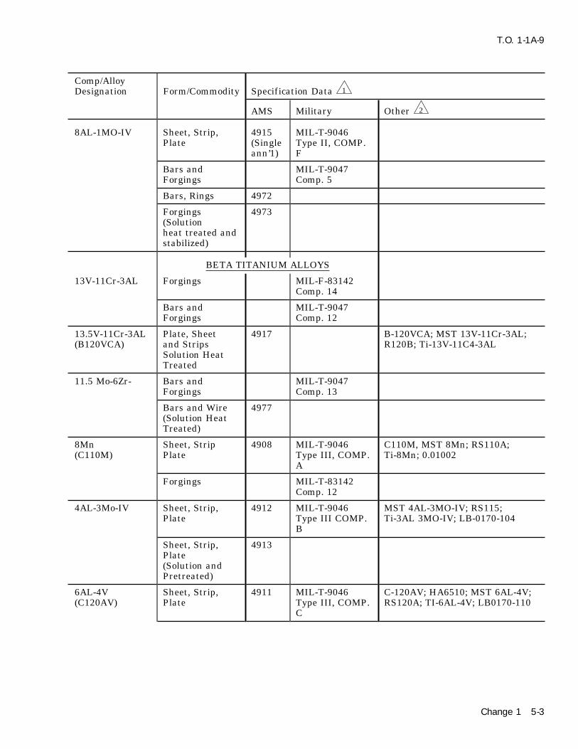
T.O. 1-1A-9
Comp/AlloyDesignation Form/Commodity Specification Data 1
AMS Military Other 2
8AL-1MO-IV Sheet, Strip, 4915 MIL-T-9046Plate (Single Type II, COMP.
ann’1) F
Bars and MIL-T-9047Forgings Comp. 5
Bars, Rings 4972
Forgings 4973(Solutionheat treated andstabilized)
BETA TITANIUM ALLOYS
13V-11Cr-3AL Forgings MIL-F-83142Comp. 14
Bars and MIL-T-9047Forgings Comp. 12
13.5V-11Cr-3AL Plate, Sheet 4917 B-120VCA; MST 13V-11Cr-3AL;(B120VCA) and Strips R120B; Ti-13V-11C4-3AL
Solution HeatTreated
11.5 Mo-6Zr- Bars and MIL-T-9047Forgings Comp. 13
Bars and Wire 4977(Solution HeatTreated)
8Mn Sheet, Strip 4908 MIL-T-9046 C110M, MST 8Mn; RS110A;(C110M) Plate Type III, COMP. Ti-8Mn; 0.01002
A
Forgings MIL-T-83142Comp. 12
4AL-3Mo-IV Sheet, Strip, 4912 MIL-T-9046 MST 4AL-3MO-IV; RS115;Plate Type III COMP. Ti-3AL 3MO-IV; LB-0170-104
B
Sheet, Strip, 4913Plate(Solution andPretreated)
6AL-4V Sheet, Strip, 4911 MIL-T-9046 C-120AV; HA6510; MST 6AL-4V;(C120AV) Plate Type III, COMP. RS120A; TI-6AL-4V; LB0170-110
C
Change 1 5-3

T.O. 1-1A-9
Table 5-1. Specification Cross Reference Titanium Alloys - Continued
Comp/AlloyDesignation Form/Commodity Specification Data 1
AMS Military Other 2
Bars and 4928 MIL-T-9047 C120AV; HA6510; MST-6AL-4V;Forgings Comp. 6 RS120A; TI-6AL-4V; LB0170-110;
0.01037
Bars and 4965Forgings(Solution &PrecipitationHeat Treated)
Extrusions 4935 C120AV; HA6510; MST-6AL-4V;RS120A; Ti-6AL-4V; LB0170-147
Wire, Welding 4954 C120AV
Forgings MIL-F-83142COMP. 6
6AL-4VEL1 Sheet, Strip, MIL-T-9046Plate Type III, COMP.
D
Bars and 4930 MIL-T-9047Forgings Comp. 7
Forgings MIL-F-83142Comp. F
Wire, Welding 4956(Extra lowintertitalenvironmentcontrolled)
6AL-6V-2Sn Forgings MIL-F-83142Comp. 8
Sheet, Strip, 4918 MIL-T-9046Plate Type III, COMP.
E
Bars and Forg- 4973 MIL-T-9046ings (Ann’1) COMP. B
4979(H.T.)
Forgings MIL-T-83142Comp. 9
7AL-4Mo Sheet, Strip, MIL-T-9046 C135MO; HA-7146; MST 7AL-(C135MO) Plate Type III, COMP. 4MO; RS 135; Ti-7AL-4MO;
F LB0170-122
Bars and 4970 MIL-T-9047Forgings (H.T.) Comp. 9
5-4

T.O. 1-1A-9
Table 5-1. Specification Cross Reference Titanium Alloys - Continued
Comp/AlloyDesignation Form/Commodity Specification Data 1
AMS Military Other 2
7AL-4Mo Forgings MIL-F-83142(C135MO) Comp. 13(Cont)
6AL-2SN- Sheet, Strip, MIL-T-90464Zr-2Mo Plate Type III, COMP.
G
Bars and 4979 MIL-T-9047Forgings (H.T.) Comp. II
4976(Ann’1)
6AL-2Sn- Bars and MIL-T-90474Zr-6Mo Forgings Comp. 14
MISCELLANEOUS SPECIFICATIONS
Heat Treatment SAE-AMS-H-of Titanium and 81200Titanium Alloys
1 There may be controlled requirements applicable to some specifications listed in the same alloytype or series. Validate any difference and assure that selected specification material(s) willcomply with end item specification requirements before specifying or using.
2 The following manufactures names apply to designations listed under other:
a. For designation beginning with A, B, C (example - A-40) CRUCIBLE STEEL CO.
b. For designation beginning with HA (example HA-1940) HARVEY ALUMINUM CO.
c. For designation beginning with MST (example MST-70) REACTIVE METAL CORP.
d. For designation beginning with RS (example RS-40) REPUBLIC STEEL CO.
e. For designation beginning with T1 (example T1-8Mn) TITANIUM METAL CORP.
f. For designation beginning with LB or NA (example LB170-110 or NA2-7123B) NORTHAMERICAN AVIATION INC.
g. For designation beginning with 0.0 (example 0.01015) CONVAIR OR GENERAL DYNAMICSCORP.
Change 4 5-5

T.O. 1-1A-9
5-14. FIRE DAMAGE. Fire damage to titanium alloys used on aerospace equipment.and titanium alloys becomes critical above 1000oF For complete description of titaniumdue to the absorption of oxygen and nitrogen from heat treat requirements, refer to lat-the air which causes surface hardening to a point est issue of SAE-AMS-H-81200.of brittleness. However, an overtemperatured con- . Additional Heat Treatment informa-dition is indicated by the formation of an oxide
tion is discussed in Section IX.coating and can be easily detected by a light greento white color. If this indication is apparent fol-
5-16. A majority of the titanium alloys can belowing fire damage to titanium aircraft parts, theeffectively heat treated to strengthen, anneal andaffected parts will be removed and replaced withstress relieve. The heating media for accomplish-serviceable parts.ing the heat treatment can be air, combusted
5-15. HEAT TREATMENT - GENERAL. gases, protective atmosphere, inert atmosphere, orvacuum furnace. However, protective, inert atmo-
NOTE spheres or vacuum shall be used as necessary toprotect all parts (titanium or titanium alloy), etc.,. SAE-AMS-H-81200, Heat Treatmentwhich comprise the furnace load to prevent reac-of Titanium and Titanium Alloys, willtion with the elements hydrogen, carbon, nitrogenbe the control document for heatand oxygen.treatment of titanium and titanium
5-6 Change 4

T.O. 1
-1A
-9
5-7
Table 5-2. Nominal Mechanical Properties at Room Temperature
ANNEALED CONDITION SOLUTION TREATED CONDITION SOLUTION TREATED ANDAGED
Yield Str Tensil Str Elong Rock Yield Str Tensil Str Elong Rock(0.2% Off (Ultimate % in well (0.2% Off (Ultimate % in well Yield Tensil Elongset) 1000 min) 1000 2 in Hard- set) 1000 min) 1000 2 in Hard- Str % in
MATERIAL TYPE psi Min psi ness psi Min psi ness 2 in
MIL-T-9046 1/
TYPE I, Comp A(Unalloyed 40 ksi) 40-65 50 20 B88Comp B(Unalloyed 70 ksi) 70-95 80 15 C23Comp C(Unalloyed 65 ksi) 55-80 65 18 B95
TYPE II, Comp A (5AL-2.5SN) 110 120 10 C35Comp B (5AL-2.5SnE11) 95 100 8-10Comp C (5AL-5Zr-5Sn) 110 120 10 C35 Not recommendedComp D (7AL-23Zr) 120 130 10Comp E (7AL-2Cb-1Ta) 110 115 10 C35Comp F (8AL-1Mo-IV) 135 145 8-10 C38
TYPE III, Comp A (8Mn) 110 120 10 Not recommendedComp B (4AL-3Mo-IV) 115 125 10 130 8 155 170 5.0Comp C (6AL-4C) 120 130 8 C36 150 160 5 145 160 5.0Comp D (6AL-4V-EL1) 120 130 10 C36Comp E (6AL-6V-2Sn) 140 150 10 160 170 10 160 170 8.0Comp F (7AL-4Mo) 135 145 10 C38 160 10 160 170 8.0
TYPE IV, Comp A (13V-11Cr-3A1) 120 125 10 120 125 10 160 170 10.0MIL-T-9047, Class 1 (Unalloyed) 70 80 15 C23
Class 2 (5AL, 2.5Sn) 110 115-120 10 C36Class 3 (3AL, 5Cr) 130 140 10Class 4 (2Fe, 2Cr, 2Mo) 120 130 15 C36Class 5 (6AL, 4V) 120 130 8 C36 145 160 5 150 160 5.0Class 6 (6AL, 4V) 130 140 10 C40 150 160 5 160 175 5.0Class 7 (5AL, 1.5Fe, 15Cr, 1.5Mo) 135 145 10 C39
NOTE 1/ Comp A, B and C are classified as commerically pure.

T.O. 1-1A-9
above 1000oF under oxidizing conditions results insevere surface scaling as well as diffusion ofCAUTIONoxygen.
Cracked ammonia or hydrogen shall 5-22. HYDROGEN EMBRITTLEMENT. Hydro-not be used as a protective atmos- gen embrittlement is a major problem with tita-phere for titanium and titanium nium and titanium alloys. Hydrogen is readilyalloys in any heat treating operations. absorbed from pickling, cleaning and scale removalsolution at room temperature and from the atmos-5-17. Air-chamber furnaces are more f lexible andphere at elevated temperatures. Hydrogen embrit-economical for large volumes of work and for lowtlement in the basically pure and alpha alloys istemperature heat treatments; but at high tempera-evident by a reduction in ductility and a slighttures where surface oxidation (above 1000oF) isincrease in strength. This is associated with asignificant, a muff le furnace utilizing externaldecrease in impact strength at temperatures belowheating gives more protection, especially if gas200oF and a shift in the temperature range whereheated. For general use, electric furnaces are pre-the change from ductile to brittle occurs. Withferred since heating can be accomplished inter-alpha-beta alloys, embrittlement is found at slownally or externally with a minimum of contamina-speeds of testing and under constant or ‘‘sus-tion. Furnaces which have given satisiactorytained’’ loads as demonstrated by tests on notchedresults are vacuum furnaces capable of supplyingspecimens. This type of embrittlement, which ispressures of one micron or less; and inert gas fur-similar to the embrittlement of steel, only becomesnaces which control the atmosphere to 1% or lessevident above a certain strength level. Solutionof oxygen and nitrogen combined.heat treating and aging the alpha-beta alloys tohigh strength levels increases sensitivity to hydro-NOTE gen embrittlement.
Avoid direct f lame impengement to5-23. Quenching from solution heat treating forprevent severe localized oxidation andtemperature wrought titanium alloys, except forcontamination. Also avoid contactalloy 3AL-13V-11Cr less than 2 inches thick,with scale or dirt.which maybe air cooled, shall be by total immer-
5-18. Alternately direct resistance heating may sion in water. The water shall be of sufficientbe used where extremely short heat up cycle on volume or circulation or both so that the waternearly finished parts is required to minimize sur- temperature upon completion of the quenchingface oxidation. operation will not be more than 100oF. The
quenching baths shall be located and arranged to5-19. The commercially pure, or unalloyed tita-permit rapid transfer of the load from the furnacenium, can only be hardened/strengthened by coldto the bath. Maximum quench delay for immer-work. Stress relief and annealing are the onlysion-type quenching shall be 4 seconds for wroughtheat treatments applicable to these alloys. Thesealloys up to 0.091 nominal thickness and 7 secondsprocesses of heat treatment are employed tofor 0.091 and over. Quench delay time beginsremove residual stress resulting from grinding,when furnace doors begin to open and ends whenwork hardening, welding, etc. For recommendedthe last corner of the load is immersed. Withtemperatures and times see Table 5-3.extremely large loads or long lengths quench delay
5-20. The soaking period for heat treatment of may be exceeded if performance test indicates thattitanium alloys shall be the minimum necesaary to all parts comply with specification requirements.develop the required mechanical properties. The
5-24. AGING AND STRESS RELIEVING. Forminimum soaking period (when unknown) shall beaging, the material shall be held within tempera-determined by teat samples run prior to heatture range for sufficient time, depending on sec-treating the finiahed material or part. Excessivetion size, for the necessary aging to take place andheat treat soaking periods ahall be avoided to pre-to insure that specified properties are developed.vent diffusion of oxygen hydrogen and nitrogen.Wrought alloys should be fully quenched by airOxygen and nitrogen diffusion will take the formcooling from the aging temperature. The sameof a hard brittle surface layer which is diff icult toapplies for stress relieving except the time at tem-distinguish from the base metal. The brittle layerperature will depend on section size plus amountmust be removed by mechanical or chemicalof cold work hardening present in the material.means prior to forming or application in stressedThe material is also quenched by air cooling fromcomponents. For the recommended soaking peri-the stress relieving temperature.ods and temperatures see Table 5-3.
5-21. Scaling (oxidation) of titanium and tita-NOTEnium alloys starts at about 900oF. Light scaling
which forms from exposure to temperatures up to All heat treating operations shall be1000oF has little or no detrimental effect on performed uniformly on the wholemechanical properties. Heating to temperatures part, etc., never on a portion thereof.
5-8

T.O. 1
-1A
-9
5-9
Table 5-3. Heat Treat, Stress Relief and Annealing Temperatures and Times
STRESS STRESS ANNEALING ANNEALING HEAT H.T. AGING AGINGRELIEF RELIEF TEMP oF TIME TREATING SOAKING TEMP oF SOAKINGTEMP oF TIME HOURS TEMP oF TIME TIME
MATERIAL HOURS MINUTES HOURS14/
Unalloyed Commercially 1000-1100 1/2-1 1000-1300 1 1/2-2 Hardened only by cold workPure Comp A, B and C 900 2-4
800 8
Alpha Alloys
5A1-2.5Sn 1080-1125 1-2 1335-1550 1/4-4 Hardened only by cold work
5A1-5Zr-5Sn 1100-1300 1/2-3/4 1335-1550 1/4-1
7A1-12Zr 1275-1325 1/2-3/4 1630-1670 1/4-1
7A1-2Cb-1Ta 2/ 1000-1200 1/3-3/4 1630-1670 1/4-1
8A1-1Mo-1V 1/ 1285-1315 1/2 1430-1470 8
Alpha-Beta Alloys
8Mn 3/ 950-1000 1/2-2 1250-1300 1 Not recommended
2Fe-2Cr-2Mo 4/ 800-1000 1/2-15 1175-1200 1/2 1650-1750 5-25 900-950 4-6
2.5A1-16V 5/ 960-990 3-5 1360-1400 1/16-1/2 1360-1400 10-30 960-990 3-5
3A1-2.5V --- --- 1250-1350 1/2-1 1/2 Not recommended
4A1-4Mn 6/ 1250-1350 1/2-2 1/2 1250-1300 2-24 1420-1480 60-120 875-925 6-10
4A1-3Mo-1V 7/ 900-1100 1/2-8 1225-1250 2-4 1620-1660 10-20 910-940 6-12
5A1-1.25Fe-2.75Cr 7/ 8/ 1000-1100 1/2-2 1425-1650 1/3-2 1350-1550 10-60 900-1000 6-10
5A1-1.5Fe-4Cr-1.2Mo 9/ 1100-1200 1/2-2 1180-1200 4-24 1650-1700 30-120 950-1050 4-8
6A1-4V 7/ 10/ 5/ 900-1200 1/2-50 1275-1550 1/2-8 1670-1730 5-25 960-990 4-6
6A1-6V-2Sn 9/ 15/ 1000-1100 1/2-3 1300-1500 2-3 1575-1675 30-60 875-1175 4-8
7A1-4Mo 11/ 900-1300 1/2-8 1425-1450 1-8 1675-1275 30-90 975-1175 4-8
6A1-4V (low o) 10/ 5/ 900-1200 1/2-50 1275-1550 1/2-8 Not recommended
Beta Alloy
3A1-13V-11Cr 12/ 900-1000 1/4-60 1430-1470 1/4-1 1375-1425 30-90 880-920 2-60
1A1-8V-5Fe 13/ 1000-1100 1/4-60 1200-1300 1/2-1 1/2 1375-1470 15-60 925-1000 1-3

T.O. 1
-1A
-9
5-1
0 Table 5-3. Heat Treat, Stress Relief and Annealing Temperatures and Times - Continued
STRESS STRESS ANNEALING ANNEALING HEAT H.T. AGING AGINGRELIEF RELIEF TEMP oF TIME TREATING SOAKING TEMP oF SOAKINGTEMP oF TIME HOURS TEMP oF TIME TIME
MATERIAL HOURS MINUTES HOURS14/
1/ Sheet: Regular anneal furnace coolDuplex anneal. Mill anneal + 1435oF, 15 minutes air cool.Triplex anneal. Mill anneal + 1850oF, 5 minutes air cool, + 1375, 15 minutes air cool.Bar and Forgings:Duplex anneal1650-1850, 1 hour air cool + 1000o-1100oF, 8-24 hours air cool.
2/ Bar Duplex anneal: Mill anneal + 1000o-1200oF, 1/2-6 hours air cool.
3/ Anneal furncee cool at 300oF per hour maximum to 1000oF to 1050oF.
4/ Stress relief may be accomplished at 800oF - 15 hours, 850oF - 5 hours, at 900oF - 1 hour and 950oF - 1/2 hour.
5/ For 100 % stress relief, 1000oF - 50 hours or 1200oF - 5 hours. For 50 % relief, 1000oF - 5 hours or 1100oF - 1/2 hour.
6/ Furnace cool at 300oF maximum from anneal temperature for maximum formability, also, formability may be improved by holding at annealing temperature 24hours.
7/ Slow cool to 1000o-1050oF maximum from upper annealing temperature.
8/ Anneal sheet at temperature for 20 minutes. For bar hold at anneal temperature 2 hours.
9/ Air cool from annealing temperature.
10/ For sheet anneal, heat 1300o-1350oF, 1 hour, furnace cool at a rate of 50oF per hour maximum to 800oF. Air cool may be used for lower ductility requirements. Forbar and forging anneal, heat at 1275o-1325oF for 2 hours, air cool. For hydrogen removal by vacuum annealing, heat at 1300oF-1500oF for 1/2-2 hours, then furnacecool to 1100oF maximum.
11/ Furnace cool from annealing temp (1425o-1450oF) to 1000o-1050oF maximum at 300oF per hour (maximum) for maximum formability. For maximum creep properties(after lowering from upper annealing) temperature hold at 1050o for 24 hours.
12/ Solution heat treatment recommended for annealing. Stress relieve at temperature cited during aging. If aging not employed, heat treat at 1000oF for 15 minutes.Aging time will depend on strength level required/desired.
13/ Furance cool from upper anneallng temperature at 300oF per hour maximum to 900oF.
14/ Longer soaking times may be necessary for specific forgings. Shorter times are satisfactory when soak time is accurately determined by thermocouples attached tothe load. Soaking time shall be measured from the time all furnace control instruments indicate recovery to the required (minimum) process range.
15/ Age at 1050o-1150oF air cool for best combination of mechanical properties and termal stability.

T.O. 1-1A-9
5-25. FABRICATION. hinge-type dies are used. When cold forming isemployed, it is usually desirable to partially form
5-26. FORMING SHEET METAL-GENERAL. the parts, stress-relieve at 1000oF for 20 minutes,The forming of the unalloyed titantum can be then finish form. Hot forming for severely con-accomplished at room temperature using approxi- toured parts or when only low-forming pressuresmately the same procedures as those extablished are available is accomplished between 600oF andfor 18-8 stainless steel. The basic diff iculties 800oF. For this procedure, the form block isencountered are sheet thickness, property varia- heated to the required temperature, the blanktions, direction of grain f low and f latness. The positioned and covered with powdered or shreddedabove factors combined with high yield strength,
asbestos; then a rubber pad 70 to 80 Durometerhigh tensile strength and low uniform elongationhardness is placed on top. This extra pad of rub-of commercial titanium alloys makes forming diff i-ber serves two purposes: First, it provides addi-cult. The current equipment available wastional rigidity for forming; and second, it protectsdesigned for material of uniform quality and con-the press-contained rubber from the hot formsiderable work is required for adaptation to formblock.titanium.
5-27. BENDING. Straight-Edge Bending of tita- 5-31. Tooling for hydropress form blocks, if ele-nium using power brake on hand forming equip- vated temperature forming is to be used, requiresment can be accomplished to a limited degree that pressure plates and dies be made somewhatusing the methods developed for stainless steel. thicker than in normal practice. If long runs areThe factors which require control are the compen- anticipated, it is recommended that form blocks besation for springback and the bend radii. Spr- made from a good grade of hot-work tool steel dueingback is comparable to that of hard stainless to the galling action of titanium at elevatedsteel when formed at room temperature. The bend temperatures.radii will depend on the type of material or alloyand whether forming is accomplished hot or cold. 5-32. STRETCH FORMING. Stretch formingThe forming of material requiring tight bends or has been used on titanium primarily to bendsmall radii necessitates the application of heat in angles, hat sections, Z-sections and channels andthe range of 500oF. The heat should be applied for to stretch form skins so that they will f it the con-only short periods of time to avoid excessive oxy- tour of the airplane fuselage. This type of forminggen and nitrogen contamination which causes is accomplished by gripping the section to beembrittlement. For approximate cold bend radii of formed in knurled jaws, loading until plastic defor-sheet titanium see Table 5-4. Actual practice may mation begins, then wrapping the part around areveal that smaller bend radii can be used. female die. This operation is performed at room
temperature and should be done at a very slow5-28. DRAW FORMING. Deep draw formingrate. Spring back is equivalent to that of 1/4 hardshould not be attempted unless adequate equip-18-8 stainless steel. All blanks for stretch-formingment and facilities are available. This will requireshould have the edges polished to remove anythat facilities be maintained for heating and con-notch effects. Approximately 0.025 inch of shearedtrolling temperatures of the blanks to be formededges should be removed.and the dies used in the forming operation.
5-29. HYDRAULIC PRESS FORMING. Rubber 5-33. DROP-HAMMER FORMING. Drop-ham-pad hydropress forming can be accomplished mer forming of titanium has been very successfuleither hot or cold depending on the type tooling and has been accomplished both at room and atemployed and the press pressures used. This type elevated temperatures. Kirksite is satisfactory forof forming is used on parts that are predominately male and female dies where only a few parts aref lat and have f langes, beads, and lightening holes. required. If long runs are to be made, ductile ironA male form block is set on the lower press platen or laminated steel dies are usually necessary. Inand the blank held in place on the block by locat- drop-hammer forming, the best results have beening pins. A press-contained rubber pad (45 to 55 obtained by warning the female die to a tempera-Shore Durometer hardness and about 8 inches
ture of 200o to 300oF to remove the chill and heat-thick) is located over the form block and blank.ing the blank to a temperature of 800o 1000oF forThe press is then closed. As the ram is lowered,10 to 15 minutes. The part is then struck and setthe rubber pad envelops the form block forcing thein the die. Usually a stress relief operation atsheet metal blank to conform to its contour.1000oF for 20 minutes is necessary, then a re-strike operation. In most instances, a f inished5-30. Many parts can be formed at room temper-part requiring no hand work is obtained.ature on the hydropress if f lange clips, wedges and
5-11

T.O. 1-1A-9
Table 5-4. Recommended Minimum CCLD Bend Radii
MINIMUM BEND RADIUS (90 DEGREE BEND) 1/TYPE/COMP 0.070 & under thickness over 0.070 to 0.187
Type I - Commercially Pure
Comp A (unalloyed 40,000 psi) 2T 2.5T
Comp B (unalloyed 70,000 psi) 2.5T 3T
Comp C (unalloyed 55,000 psi) 2T 2.5T
Type II - Alpha Titanium Alloy
Comp A (5AL02.5Sn) 4T 4.5T
Comp B (5AL-2.5Sn EL1) 4T 4.5T
Comp C (5AL-5Zr-5Sn) 4.5T 5T
Comp D (7AL-12Zr) 5T 5T
Comp E (7AL-2Cb-1Ta) -- --
Comp F (8AL- 1Mo-1V) 4.5T 5T
Type III - Alpha-Beta
Comp A (8Mn) 3T 3.5T
Comp B (4AL-3Mo-1V) 3.5T 4T
Comp C (6AL-4V) 4.5T 5T
Comp D (6AL-4V) 4.5T 5T
Comp E (6AL-6V-2Sn) -- --
Comp F (7AL-4Mo) -- --
Type IV - Beta
Comp A (13V-11Cr-3AL) 3T 3-5T
1/ T = Thickness of material. Example: A piece of 0.040 MIL-T-9046, Type II, Composition A, wouldrequire a bend radii of 4 x 0.040 = 0.160 bend radii (minimum).
5-34. JOGGLING. Joggling of titanium can be 5-35. BLANKING AND SHEARING. Theseaccomplished without any particular diff iculty pro- operations compare to those of 18-8 stainless steelvided the following rules are adhered to: in the 1/4 hard condition for commercially pure,
and the alloys compare to 1/2 hard 18-8 stainlessa. The joggle die corner radius should not be steel. The force required for titanium and itsless than 3T-8T. alloys is greater and the dies wear faster. Materi-als up to 0.125 inch in thickness have beenb. Joggle run-out should be the determiningsheared on 1/2 inch capacity f lat bed shearsfactors whether joggles are formed hot or cold.designed for steel. If this capacity is to beJoggles should be formed hot where a ratio of jog-exceeded, the shear designer should be consulted.gle run-out to joggle depth is less than 8.1.
c. Minimum joggle run-outs should be as 5-36. Before any forming or other operations arefollows: performed 0.025 inch of the sheared, blanked,
sawed, or nibbed edges should be removed to pre-Hot joggling - four times the jogglevent stress risers that will cause a tear in the partdepth.during forming operations.
Cold joggling - eight times the joggledepth. 5-37. Deleted.
Paragraphs 5-38 through 5-42 deleted.Pages 5-13 through 5-14 deleted.
5-12 Change 2

T.O. 1-1A-9
5-43. Deleted. increased about 65% over that required for highstrength aluminum rivets. Better results can be5-44. Deleted. obtained by using the squeeze method rather thanthe rivet gun and bucking bar. When it is neces-5-45. Deleted.sary to have f lush-head rivets, dimpling can be
5-46. Deleted. accomplished at temperatures of 500oF to 700oF.Other types of rivets such as high strength alumi-5-47. SOLDERING. Limited information isnum, stainless steel and monel are also used toavailable on soldering. It is possible to success-join titanium.fully solder titanium where little strength is
required, by precoating with a thin film of silver, 5-49. Due to diff iculties involved, the above men-copper or tin from their chloride salts. This can be tioned method will probably be replaced in mostaccomplished by heating the chloride salts-coated cases with rivets of the high shear series, i.e., pintitanium in an atmosphere controlled furnace as rivets such as NAS1806 through NAS1816, tensionpreviously mentioned in paragraph 5-18. The rivet NAS-2006 through NAS-2010, and shearresultant film should be made wet with either a rivet NAS-2406 through NAS-2412.60% tin-40% lead or a 50%-50% tin and lead sol-
5-50. As with other metals, it is necessary toder. Since the deposited film may dissolve in thetake precautions to avoid galvanic corrosion whenliquid solder and dewet the surface, it is importanttitanium is riveted to other metals. This can bethat the time and temperature be held to aaccomplished by coating the titanium with zincminimum.chromate primer Specification MIL-P-8585.
5-48. RIVETING. Riveting of titanium can beaccomplished using conventional equipment withrivets manufactured from commercially pure mate-rial; however, the rivet holes require close toler-ances to insure good gripping. The driving time is
Table 5-5 deleted.
Change 1 5-15/(5-16 blank)


T.O. 1-1A-9
5-51. MACHINING AND GRINDING. if there is any lost motion in the feed mechanismof the table, the piece being cut will be pulled into
5-52. MACHINING. Commercially pure, unal- the cutter. This may damage the cutter or theloyed titanium machines similarly to 18-8 stainless work piece.steel, but the alloy grades are somewhat harder.Variations in actual practice will depend on the 5-59. For effective milling, the work feed shouldtype of work, equipment, and finish, so the follow- move in the same direction as the cutting teeth,ing information is only intended as a guide. and for face milling the teeth should emerge from
the cut in the same direction that the work is fed.5-53. The basic requirements are: rigid machinesetups, use of a good cutting f luid that emphasizes 5-60. To select the appropriate tool material it iscooling rather than lubrication, sharp and proper advisable to try both cast alloy and carbide tools totools, slow speeds and heavy feeds. Since titanium determine the better of the two for large millinghas a tendency to gall and seize on other metals, jobs. This should be done since the cutter usuallythe use of sharp tools is very important. Sliding fails because of chipping, and the results are notcontact, and riding of the tool on the work must be as satisfactory with carbide as they are with cast-avoided. alloy tools. The increase in cutting speeds (20 to
30%) possible by using carbide rather than cast5-54. TURNING. Commercially pure and alloy (all alloy tools) does not always compensate for thetitanium is not diff icult to turn. Carbide tools additional tool grinding cost.such as metal carbides C91 and Carboloy 44A andother similar types give the best results for turn- 5-61. The same water-base cutting f luids useding titanium. Cobalt-type high speed steels give for turning are recommended for milling; however,the best results of the many types available. Cast carbide tools may give better results when dry.alloy tools such as Stellite, Lantung, Rexalloy, etc.,
5-62. See Table 5-8 for recommended speed andmay be used when carbide is not available, orfeeds. For tool grinding information see Table 5-9.when the high speed steels, are not satisfactory.
5-63. DRILLING. Drilling of titanium can be5-55. The recommended cutting f luids areaccomplished successfully with ordinary highwaterbase cutting f luids such as soluble oils orspeed steel drills. Low speeds and heavy positivechemical type f luids.feeds are required. The unsupported portion of
5-56. Tables 5-6 and 5-7 show suggested turning the drill should be as short as possible to providespeeds, tool angles and feeds. All work should be maximum rigidity and to prevent drill running.accomplished with live centers since galling or All holes should be drilled without pilot holes ifseizing will occur on dead centers. Tool sharpness possible. As with other materials, chip removal isis again emphasized because a nick or a seized one of the principal problems and the appearancechip on a tool increases temperature and will of the chip is an indication of the sharpness andcause rapid tool failures. correct grinding of the drill. In drilling deep holes,
intermittent drilling is recommended. That is, the5-57. MILLING. Considering the type of tool drill is removed from the hole at intervals towhich is required in milling operations, it can be remove the chips.readily seen that this type of machining is moredifficult than turning. The diff iculty encountered 5-64. The cutting f luids recommended are sulfu-is that chips remain tightly welded to the cutter’s rized and chlorinated coolants for drills with diam-edge at the end of cut or during the portion of the eters of less than 1/4 inch and mixtures of mineralrevolution that it does not cut. As the cutter oil or soluble oil with water for hole sizes largerstarts the next machining portion the chips are than 1/4 inch diameter.knocked off. This damages the cutting edge and
5-65. The cutting speed should be 50 to 60 FPMthe tool fails rapidly.for the pure grade of titanium and 30 to 50 FPM
5-58. One method that can be utilized to relieve for alloy grades. Feeds should be 0.005 to 0.009this diff iculty to a great extent is climb milling. inch for 1/4 to 1/2 inch diameter drills; 0.002 toThe cutter machines the thinnest portion of the 0.005 inch for smaller drills. Point angle, 90o forchip as it leaves the cut. Thus, the area of contact drills 1/4 inch diameter and larger and 140o forbetween chip and tool is at a minimum when the drills 1/8 inch diameter or less; but 90o, 118o andchip is removed at the start of the next cutting 140o should be tried on large jobs to determine theportion of the revolution. This will reduce the angle that will give the best result. Helix angledanger of chipping the tool. The machine used for 28o to 35o and lip relief 10o. Additional informationclimb milling should be in good condition because on drills may be obtained from NAS907.
5-17
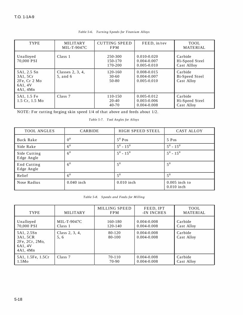
T.O. 1-1A-9
Table 5-6. Turning Speeds for Titanium Alloys
TYPE MILITARY CUTTING SPEED FEED, in/rev TOOLMIL-T-9047C FPM MATERIAL
Unalloyed Class 1 250-300 0.010-0.020 Carbide70,000 PSI 150-170 0.004-0.007 Hi-Speed Steel
170-200 0.005-0.010 Cast Allloy
5A1, 2.5 Sn Classes 2, 3, 4, 120-160 0.008-0.015 Carbide3A1, 5Cr 5, and 6 30-60 0.004-0.007 Bi-Speed Steel2Fe, Cr 2 Mo 50-80 0.005-0.010 Cast Alloy6A1, 4V4A1, 4Mn
5A1, 1.5 Fe Class 7 110-150 0.005-0.012 Carbide1.5 Cr, 1.5 Mo 20-40 0.003-0.006 Hi-Speed Steel
40-70 0.004-0.008 Cast Alloy
NOTE: For cutting forging skin speed 1/4 of that above and feeds about 1/2.
Table 5-7. Tool Angles for Alloys
TOOL ANGLES CARBIDE HIGH SPEED STEEL CAST ALLOY
Back Rake 0o 5o Pos 5 Pos
Side Rake 6o 5o - 15o 5o - 15o
Side Cutting 6o 5o - 15o 5o - 15o
Edge Angle
End Cutting 6o 5o 5o
Edge Angle
Relief 6o 5o 5o
Nose Radius 0.040 inch 0.010 inch 0.005 inch to0.010 inch
Table 5-8. Speeds and Feeds for Milling
MILLING SPEED FEED, IPT TOOLTYPE MILITARY FPM -IN INCHES MATERIAL
Unalloyed MIL-T-9047C 160-180 0.004-0.008 Carbide70,000 PSI Class 1 120-140 0.004-0.008 Cast Alloy
5A1, 2.5Sn Class 2, 3, 4, 80-120 0.004-0.008 Carbide3A1, 5CR 5, 6 80-100 0.004-0.008 Cast Alloy2Fe, 2Cr, 2Mo,6A1, 4V4A1, 4Mn
5A1, 1.5Fe, 1.5Cr Class 7 70-110 0.004-0.008 Carbide1.5Mo 70-90 0.004-0.008 Cast Alloy
5-18

T.O. 1-1A-9
Table 5-9. Angles for Tool Grinding c. Cutting f luid; Active cutting oil such as oil,cutting, sulfurized mineral, Specification VV-O-283, Grade 1.
CAST ALLOY CARBIDE5-69. REAMING. Preparation of the hole to beANGLES TOOL TOOLreamed and the type of reamer used is the key-note to successful reaming operations. As withAxial Rake 0o 0o
tapping operations, the hole to be reamed shouldRadial Rake 0o 0o
be drilled with a sharp drill. A straight-f lutedreamer can be used, but spiral-f luted reamersCorner Angle 30o 60o
with carbide tips usually produce the best results.End Cutting 6o 6o
Speeds of 40-200 FPM and feeds of 0.005 to 0.008Edge Angle inch are satisfactory; however, these factors
depend on the size of the hole. Feeds shouldRelief 12o 6-10o
increase in proportion to the size of the hole. Theremoval of larger amounts lessens the degree of5-66. TAPPING. Due to the galling and seizingconcentricity. If the degree of concentricity is anthat are characteristic of titanium, tapping is oneimportant factor, smaller amounts should beof the more diff icult machining operations. Chipremoved.removal is one of the problems that will require
considerable attention in an effort to tap titanium. 5-70. GRINDING. The essential requirementsAnother problem will be the smear of titanium. for grinding are the selection and use of grindingBuild up from smear will cause the tap to freeze or f luids and abrasive wheels. Grinding of titaniumbind in the hole. These problems can be alleviated is different from grinding steel in that the abra-to some extent by the use of an active cutting f luid sive grain of the wheel wears or is dissolved by asuch as sulphurized and chlorinated oil. surface reaction, rather than wheel wear which is
caused by breakage. To overcome this problem,5-67. Power equipment should be used when pos-lower wheel speeds and the use of aluminum oxidesible and a hole to be tapped should be drilledor soft bonded silicone carbide wheels employingwith a sharp drill to prevent excessive hardeningwet grinding methods are recommended. Recom-of the hole wall. In the attempt to tap titanium,mended wheel speeds are; 1500-2000 SFPM anddifficulties involved can be minimized by reducingtable feeds of 400 to 500 inches per minute withthe thread to 55 or 65% from the standard 78%.down feed of 0.001 inch maximum per pass and
5-68. The following are procedures and material using 0.05 inch cross feed for highest grindingrecommended for tapping titanium: ratios.
a. Cutting speed: 40 to 50 FPM for unalloyedand 20 to 30 FPM for the alloy grades.
b. Type of Tap: Gun or spiral point, 2 f lutedin sizes 1/4-20 or 1ess; 3 f luted in sizes greaterthan 1/4-20.
5-19/(5-20 blank)


T.O. 1-1A-9
SECTION VI
COPPER AND COPPER BASE ALLOYS
6-1. COPPER AND COPPER BASE ALLOYS. and has an electrical conductivity of 20%. Berryl-lium-coppers are widely used for tools where non-6-2. Most of the commercial coppers are refined sparking qualities are desired.to a purity of 99.90%, minimum copper plus silver.
The two principal copper base alloys are brass and MANGANESE - Added primarily as a desulfuriz-bronze, containing zinc and tin respectively, as the ing and de-gassifying element for alloys containingmajor alloying element. Alloy designations for nickel.wrought copper and copper alloys are listed in
6-4. CHEMICAL COMPOSITION. - The chemi-table 6-1, with the corresponding specification andcal composition of the copper alloys (listed by com-common trade names.mercial trade name) is listed in table 6-1.
6-3. COPPER ALLOYING ELEMENTS.6-5. HEAT TREATMENT AND NOT WORKING
ZINC - Added to copper to form a series of alloys TEMPERATURE OF COPPER ALLOYS.known as brasses. They are ductile, malleable,corrosion resistant and have colors ranging from NOTEpink to yellow.
Additional Heat Treatment informa-TIN - Added to copper to form a series of alloys tion is discussed in Section IX.known as bronzes. Bronzes are a quality spring
6-6. During production and fabrication, coppermaterial, and are strong, ductile and corrosionalloys may be heated for homogenizing, hot work-resistant.ing, stress relief for solution treatment, and pre-
LEAD - Added to copper in amounts up to 1% to cipitation hardening. The temperatures commonlyform a machinable, high-conductivity copper rod. used for heating, hot working and annealing afterIt is added to brasses or bronzes in amounts of 0.5 cold working are given in table 6-2.to 4% to improve machinability and in the range of2 -4% to improve bearing properties. 6-7. STRESS RELIEF OF COPPER ALLOYS.
ALUMINUM - Added to copper as a predominat- 6-8. Table 6-3 below gives a list of typical stressing alloy element to form a series known as alumi- relief treatments commonly used in industry. Thisnum bronzes. These alloys are of high strength table is listed in terms of chemical compositionand corrosion resistance. percents, and should be used as representing aver-
age stress relieving temperatures.IRON - Added to copper along with aluminum insome aluminum bronzes and with manganese in 6-9. MACHINING COPPER AND COPPERsome manganese bronzes. ALLOYS. Free cutting brass is one of the most
easily machined metals and serves as a standardPHOSPHOROUS - Added to copper principally asfor machinability ratings of copper alloys. The fol-a deoxidizer and in some bronzes to improvelowing table gives the machinability ratings andspring properties.recommended speeds and feeds for use with high
NICKEL - Added to copper for higher strength speed steel tools.without loss of ductility. They have excellent cor-rosion resistance. 6-10. WROUGHT-COPPER-BERYLLIUM
ALLOYS. The beryllium copper alloys are fre-SILICON - Added to copper to form the copper - quently used due to their ability to respond to pre-silicon series having high corrosion resistance com- cipitation or age hardening treatments and otherbined with strength and superior welding quali- beneficial characteristics. Some of the characteris-ties. Small amounts are used as deoxidizers. tics are; good electrical and thermal conductivity,BERYLLIUM - Added to copper to form a series of high strength hardness, corrosion resistance, goodage hardenable alloys. In the fully treated condi- wear resistance, non-magnetic qualities and verytion, it is the strongest of the copper base alloys good fatigue strength.
6-1

T.O. 1-1A-9
Table 6-1. Chemical Composition by Trade Name
COPPER SPECIFICATIONALLOYNO. FEDERAL MILITARY TRADE NAME
101 QQ-A-673, type II MIL-W-85C Oxygen free certif ied copper.QQ-C-502QQ-C-576QQ-W-343WW-P-377
102 QQ-A-673Type II MIL-W-85C Oxygen free copper.QQ-C-502 MIL-W-6712AQQ-C-825QQ-C-576QQ-R-571, ClassFS-RCu-1QQ-W-343WW-T-799
104 QQ-C-502 Oxygen free with silver.QQ-C-825
105 QQ-C-502 Oxygen free with silver.QQ-C-825
110 QQ-A-673, Type I MIL-W-3318 Electrolyte Tough pitchQQ-C-502 MIL-W-6712 copper.QQ-C-825QQ-C-576
128 QQ-C-502 Fire refined tough pitchQQ-C-576 with silver.
130 QQ-C-502 Fire refined tough pitchQQ-C-576 with silver.
170 QQ-C-530 Beryllium Copper172 QQ-C-533
210 QQ-W-321, Gilding, 95%comp 1
220 QQ-W-321, MIL-W-85C Commercial bronze, 90%comp 2 MIL-W-6712
230 QQ-B-613,comp 4 Red Brass, 85%QQ-B-626,comp 4QQ-W-321comp 3WW-P-351Grade AWW-T-791Grade 1
6-2

T.O. 1-1A-9
Table 6-1. Chemical Composition by Trade Name - Continued
COPPER SPECIFICATIONALLOYNO. FEDERAL MILITARY TRADE NAME
240 QQ-B-591 Low Brass, 80%QQ-B-613comp 3QQ-B-626comp 3QQ-B-650comp DQQ-W-321 JAN-W-472comp 4
260 QQ-B-613 *MIL-S-22499 Cartridge brass, 70%comp 2 and 11QQ-B-626 MIL-T-6945comp 2 and 11 comp IIQQ-B-650 MIL-T-20219comp CQQ-W-321comp 6
*Laminated ShimStock
261 Same as 260
262 QQ-B-613comp 11QQ-B-626comp 11
268 QQ-B-613 Yellow brass, 66% (Sheet)comp 1 and 11QQ-B-626comp 1 and 11
270 QQ-B-613 Yellow brass, 65% (rod and wire)comp 11QQ-B-626comp 11QQ-W-321comp 7
274 QQ-B-613 Yellow brass 63%comp 11QQ-B-626comp 11QQ-W-321comp 8
6-3
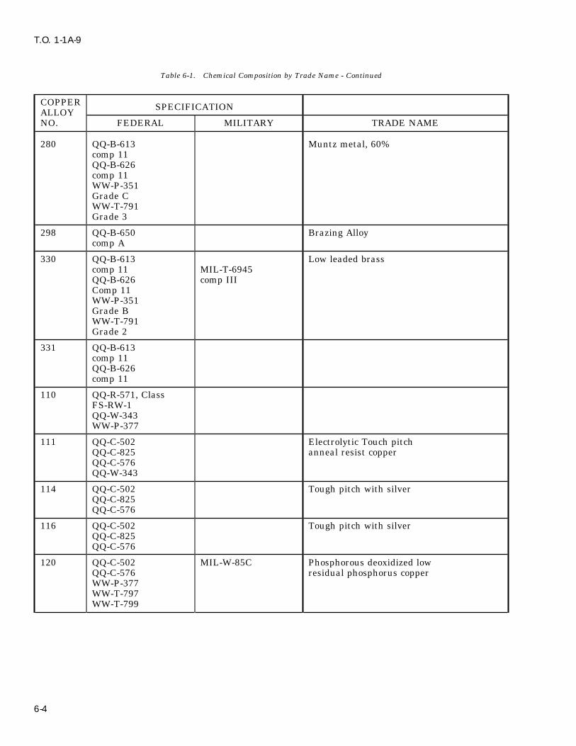
T.O. 1-1A-9
Table 6-1. Chemical Composition by Trade Name - Continued
COPPER SPECIFICATIONALLOYNO. FEDERAL MILITARY TRADE NAME
280 QQ-B-613 Muntz metal, 60%comp 11QQ-B-626comp 11WW-P-351Grade CWW-T-791Grade 3
298 QQ-B-650 Brazing Alloycomp A
330 QQ-B-613 Low leaded brasscomp 11 MIL-T-6945QQ-B-626 comp IIIComp 11WW-P-351Grade BWW-T-791Grade 2
331 QQ-B-613comp 11QQ-B-626comp 11
110 QQ-R-571, ClassFS-RW-1QQ-W-343WW-P-377
111 QQ-C-502 Electrolytic Touch pitchQQ-C-825 anneal resist copperQQ-C-576QQ-W-343
114 QQ-C-502 Tough pitch with silverQQ-C-825QQ-C-576
116 QQ-C-502 Tough pitch with silverQQ-C-825QQ-C-576
120 QQ-C-502 MIL-W-85C Phosphorous deoxidized lowQQ-C-576 residual phosphorus copperWW-P-377WW-T-797WW-T-799
6-4
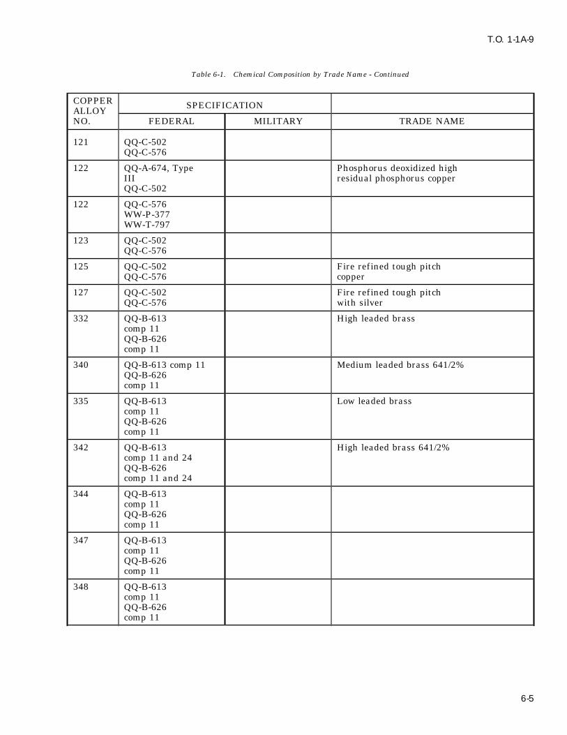
T.O. 1-1A-9
Table 6-1. Chemical Composition by Trade Name - Continued
COPPER SPECIFICATIONALLOYNO. FEDERAL MILITARY TRADE NAME
121 QQ-C-502QQ-C-576
122 QQ-A-674, Type Phosphorus deoxidized highIII residual phosphorus copperQQ-C-502
122 QQ-C-576WW-P-377WW-T-797
123 QQ-C-502QQ-C-576
125 QQ-C-502 Fire refined tough pitchQQ-C-576 copper
127 QQ-C-502 Fire refined tough pitchQQ-C-576 with silver
332 QQ-B-613 High leaded brasscomp 11QQ-B-626comp 11
340 QQ-B-613 comp 11 Medium leaded brass 641/2%QQ-B-626comp 11
335 QQ-B-613 Low leaded brasscomp 11QQ-B-626comp 11
342 QQ-B-613 High leaded brass 641/2%comp 11 and 24QQ-B-626comp 11 and 24
344 QQ-B-613comp 11QQ-B-626comp 11
347 QQ-B-613comp 11QQ-B-626comp 11
348 QQ-B-613comp 11QQ-B-626comp 11
6-5

T.O. 1-1A-9
Table 6-1. Chemical Composition by Trade Name - Continued
COPPER SPECIFICATIONALLOYNO. FEDERAL MILITARY TRADE NAME
350 QQ-B-613 Medium leaded brass 62%comp 11QQ-B-626comp 11
353 QQ-B-613 Extra High leaded brasscomp 11QQ-B-626comp 11
356 QQ-B-613 Extra High leaded brasscomp 11QQ-B-626comp 11 and 22
370 QQ-B-613 Free cutting muntz metalcomp 11QQ-B-626comp 11
360 QQ-B-613 Free cutting brasscomp 11QQ-B-626comp 11 and 22
377 QQ-B-626 Forging brasscomp 21
443 WW-T-756 Admiralty, Arsenical
444 WW-T-756 Admiralty, Antimonial
445 WW-T-756 Admiralty, Phosphorized
462 QQ-B-626 Naval Brass, 631/2%comp 11QQ-B-637comp 4
464 QQ-B-613 Naval Brasscomp 11 MIL-W-6712QQ-B-626comp 11 MIL-T-6945QQ-B-637 comp 1comp 1
465 QQ-B-613 MIL-W-6712 Naval brass, arsenicalcomp 11QQ-B-626 MIL-T-6945comp 11QQ-B-637 comp 1comp 1
6-6
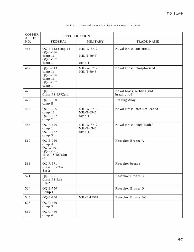
T.O. 1-1A-9
Table 6-1. Chemical Composition by Trade Name - Continued
COPPER SPECIFICATIONALLOYNO. FEDERAL MILITARY TRADE NAME
466 QQ-B-613 comp 11 MIL-W-6712 Naval Brass, antimonialQQ-B-626comp 11 MIL-T-6945QQ-B-637comp 1 comp 1
467 QQ-B-613 MIL-W-6712 Naval Brass, phosphorizedcomp 11 MIL-T-6945QQ-B-626comp 11QQ-B-637comp 1
470 QQ-R-571 Naval brass, welding andClass FS-RWZn-1 brazing rod
472 QQ-B 650 Brazing Alloycomp B
482 QQ-B-626 MIL-W-6712 Naval Brass, medium leadedcomp 11 MIL-T-6945QQ-B-637 comp 1comp 2
485 QQ-B-626 MIL-W-6712 Naval Brass, High leadedcomp 1 MIL-T-6945QQ-B-637 comp 1comp 3
510 QQ-B-750 Phosphor Bronze Acomp AQQ-W-401QQ-R-571,class FS-RCuSm-2
518 QQ-R-571 Phosphor bronzeClass FS-RCuSm-2
521 QQ-R-571 Phosphor Bronze CClass FS-RcuSm-2
524 QQ-B-750 Phosphor Bronze DComp D
544 QQ-B-750 MIL-B-13501 Phosphor Bronze B-2
606 QQ-C-450comp 3
612 QQ-C-450comp 4
6-7

T.O. 1-1A-9
Table 6-1. Chemical Composition by Trade Name - Continued
COPPER SPECIFICATIONALLOYNO. FEDERAL MILITARY TRADE NAME
614 QQ-C-450comp 5 Aluminum Bronze D
618 MIL-W-6712MIL-R-18818MIL-RUA1-2
622 MIL-R-18818 classMIL-RCA-B
651 QQ-C-591 Low silicon bronze Bcomp B
655 QQ-C-591comp A MIL-T-8231 High Silicon Bronze A
656 QQ-R-571Class FS-RCuS1 MIL-E13191 class
MIL-EcuSi-A
658 MIL-E-13191 classMIL-ECuSi-A
661 QQ-C-591comp D
670 QQ-B-728 Manganese Bronze BClass B
675 QQ-B-728 Manganese Bronze AClass A
680 QQ-R-571 Bronze Low Fuming (Nickel)Class FS-RCu-Zn-3
681 QQ-R-571 class Bronze, Low FumingFS-RCuZn-2
692 QQ-C-591 Silicon BrassComp E
715 QQ-R-571 Class Copper Nickel 30%FS-RCuNi
735 QQ-C-585comp 6
745 QQ-C-585 Nickel Silver 65-10comp 5QQ-C-586comp 5QQ-W-340comp 5
6-8

T.O. 1-1A-9
Table 6-1. Chemical Composition by Trade Name - Continued
COPPER SPECIFICATIONALLOYNO. FEDERAL MILITARY TRADE NAME
752 QQ-C-585 Nickel Silver 65-18comp 1QQ-C-586comp 1QQ-W-340comp 1
764 QQ-C-586comp 3QQ-W-340comp 3
766 QQ-C-585comp 7
770 QQ-C-585 Nickel Silver 55-18comp 2QQ-C-586comp 2QQ-W-340comp 2
794 QQ-C-586comp 4QQ-W-340comp 4
Table 6-2. Hot Working and Annealing Temperatures for Copper and Wrought Copper Alloys
COMMERCIAL CHEMICAL HOT WORKING ANNEALING TEMPDESIGNATION COMPOSITION TEMP oF oF
Copper, commercially 99,93 Cu 1300 to 1650 700 to 1200pure
Gilding Metal 95 Cu, 5 Zn 1300 to 1650 800 to 1450
Commercial Bronze 90 Cu, 10 Zn 1400 to 1600 800 to 1450
Red Brass 85 Cu, 15 Zn 1450 to 1650 800 to 1350
Low Brass 80 Cu, 20 Zn 1450 to 1650 800 to 1300
Cartridge Brass 70 Cu, 30 Zn 1350 to 1550 800 to 1300
Yellow Brass 65 Cu, 35 Zn (a) 800 to 1300
Muntz Metal 60 Cu, 40 Zn 1150 to 1450 800 to 1100
Leaded Commercial 89 Cu, 9.25 Zn, (a) 800 to 1200Bronze 1.75 Pb
Low Leaded Brass 64.5 Cu, 35 Zn, (a) 800 to 13000.5 Pb
Medium Leaded Brass 64.5 Cu, 34.5 Zn, (a) 800 to 12001 Pb
6-9
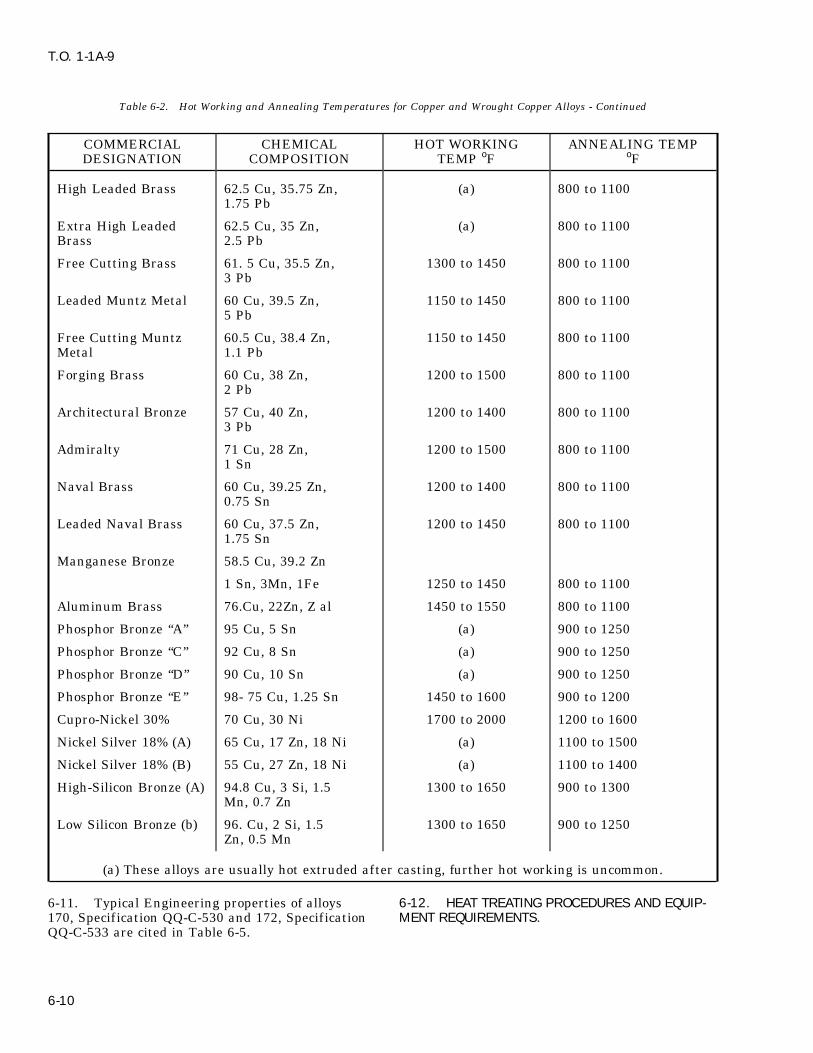
T.O. 1-1A-9
Table 6-2. Hot Working and Annealing Temperatures for Copper and Wrought Copper Alloys - Continued
COMMERCIAL CHEMICAL HOT WORKING ANNEALING TEMPDESIGNATION COMPOSITION TEMP oF oF
High Leaded Brass 62.5 Cu, 35.75 Zn, (a) 800 to 11001.75 Pb
Extra High Leaded 62.5 Cu, 35 Zn, (a) 800 to 1100Brass 2.5 Pb
Free Cutting Brass 61. 5 Cu, 35.5 Zn, 1300 to 1450 800 to 11003 Pb
Leaded Muntz Metal 60 Cu, 39.5 Zn, 1150 to 1450 800 to 11005 Pb
Free Cutting Muntz 60.5 Cu, 38.4 Zn, 1150 to 1450 800 to 1100Metal 1.1 Pb
Forging Brass 60 Cu, 38 Zn, 1200 to 1500 800 to 11002 Pb
Architectural Bronze 57 Cu, 40 Zn, 1200 to 1400 800 to 11003 Pb
Admiralty 71 Cu, 28 Zn, 1200 to 1500 800 to 11001 Sn
Naval Brass 60 Cu, 39.25 Zn, 1200 to 1400 800 to 11000.75 Sn
Leaded Naval Brass 60 Cu, 37.5 Zn, 1200 to 1450 800 to 11001.75 Sn
Manganese Bronze 58.5 Cu, 39.2 Zn
1 Sn, 3Mn, 1Fe 1250 to 1450 800 to 1100
Aluminum Brass 76.Cu, 22Zn, Z al 1450 to 1550 800 to 1100
Phosphor Bronze ‘‘A’’ 95 Cu, 5 Sn (a) 900 to 1250
Phosphor Bronze ‘‘C’’ 92 Cu, 8 Sn (a) 900 to 1250
Phosphor Bronze ‘‘D’’ 90 Cu, 10 Sn (a) 900 to 1250
Phosphor Bronze ‘‘E’’ 98- 75 Cu, 1.25 Sn 1450 to 1600 900 to 1200
Cupro-Nickel 30% 70 Cu, 30 Ni 1700 to 2000 1200 to 1600
Nickel Silver 18% (A) 65 Cu, 17 Zn, 18 Ni (a) 1100 to 1500
Nickel Silver 18% (B) 55 Cu, 27 Zn, 18 Ni (a) 1100 to 1400
High-Silicon Bronze (A) 94.8 Cu, 3 Si, 1.5 1300 to 1650 900 to 1300Mn, 0.7 Zn
Low Silicon Bronze (b) 96. Cu, 2 Si, 1.5 1300 to 1650 900 to 1250Zn, 0.5 Mn
(a) These alloys are usually hot extruded after casting, further hot working is uncommon.
6-11. Typical Engineering properties of alloys 6-12. HEAT TREATING PROCEDURES AND EQUIP-170, Specification QQ-C-530 and 172, Specification MENT REQUIREMENTS.QQ-C-533 are cited in Table 6-5.
6-10
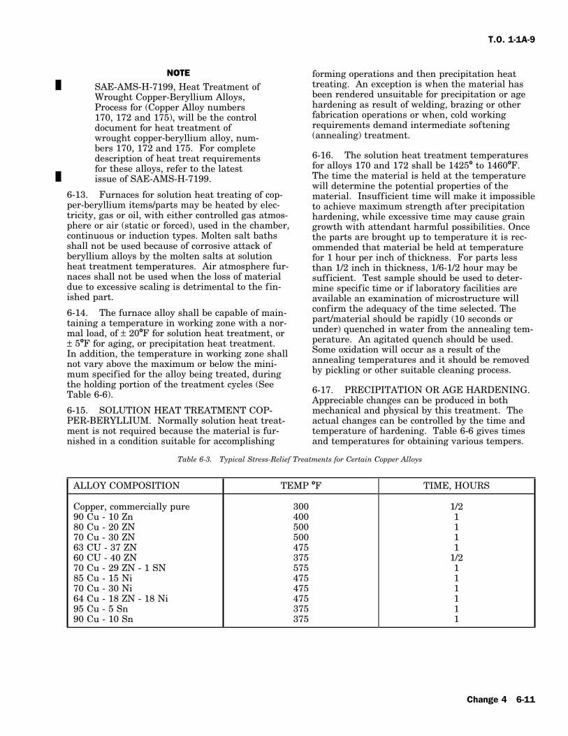
T.O. 1-1A-9
NOTE forming operations and then precipitation heattreating. An exception is when the material hasSAE-AMS-H-7199, Heat Treatment ofbeen rendered unsuitable for precipitation or ageWrought Copper-Beryllium Alloys,hardening as result of welding, brazing or otherProcess for (Copper Alloy numbersfabrication operations or when, cold working170, 172 and 175), will be the controlrequirements demand intermediate softeningdocument for heat treatment of(annealing) treatment.wrought copper-beryllium alloy, num-
bers 170, 172 and 175. For complete6-16. The solution heat treatment temperaturesdescription of heat treat requirementsfor alloys 170 and 172 shall be 1425o to 1460oF.for these alloys, refer to the latestThe time the material is held at the temperatureissue of SAE-AMS-H-7199.will determine the potential properties of the
6-13. Furnaces for solution heat treating of cop- material. Insufficient time will make it impossibleper-beryllium items/parts may be heated by elec- to achieve maximum strength after precipitationtricity, gas or oil, with either controlled gas atmos- hardening, while excessive time may cause grainphere or air (static or forced), used in the chamber, growth with attendant harmful possibilities. Oncecontinuous or induction types. Molten salt baths the parts are brought up to temperature it is rec-shall not be used because of corrosive attack of ommended that material be held at temperatureberyllium alloys by the molten salts at solution for 1 hour per inch of thickness. For parts lessheat treatment temperatures. Air atmosphere fur- than 1/2 inch in thickness, 1/6-1/2 hour may benaces shall not be used when the loss of material sufficient. Test sample should be used to deter-due to excessive scaling is detrimental to the fin- mine specific time or if laboratory facilities areished part. available an examination of microstructure will
confirm the adequacy of the time selected. The6-14. The furnace alloy shall be capable of main-part/material should be rapidly (10 seconds ortaining a temperature in working zone with a nor-under) quenched in water from the annealing tem-mal load, of ± 20oF for solution heat treatment, orperature. An agitated quench should be used.± 5oF for aging, or precipitation heat treatment.Some oxidation will occur as a result of theIn addition, the temperature in working zone shallannealing temperatures and it should be removednot vary above the maximum or below the mini-by pickling or other suitable cleaning process.mum specified for the alloy being treated, during
the holding portion of the treatment cycles (See 6-17. PRECIPITATION OR AGE HARDENING.Table 6-6). Appreciable changes can be produced in both6-15. SOLUTION HEAT TREATMENT COP- mechanical and physical by this treatment. ThePER-BERYLLIUM. Normally solution heat treat- actual changes can be controlled by the time andment is not required because the material is fur- temperature of hardening. Table 6-6 gives timesnished in a condition suitable for accomplishing and temperatures for obtaining various tempers.
Table 6-3. Typical Stress-Relief Treatments for Certain Copper Alloys
ALLOY COMPOSITION TEMP oF TIME, HOURS
Copper, commercially pure 300 1/290 Cu - 10 Zn 400 180 Cu - 20 ZN 500 170 Cu - 30 ZN 500 163 CU - 37 ZN 475 160 CU - 40 ZN 375 1/270 Cu - 29 ZN - 1 SN 575 185 Cu - 15 Ni 475 170 Cu - 30 Ni 475 164 Cu - 18 ZN - 18 Ni 475 195 Cu - 5 Sn 375 190 Cu - 10 Sn 375 1
Change 4 6-11

T.O. 1-1A-9
Table 6-4. Standard Machinability Rating of Copper Alloys
ALLOY MACHINA- SURFACE ROUGHING FINISHINGDESIGNATION BILITY SPEED FEED, INCH FEED, INCH
RATING FEET PERMINUTE
Leaded Copper 80 300 to 700 0.006 to 0.020 0.003 to 0.015Leaded Commercial 300 to 700 0.006 to 0.020 0.003 to 0.015Bronze 80 300 to 700 0.006 to 0.020 0.003 to 0.015Low Leaded Brass 60 300 to 700 0.006 to 0.020 0.003 to 0.015Medium Leaded Brass 70 300 to 700 0.006 to 0.020 0.003 to 0.015High Leaded Brass 90 300 to 700 0.006 to 0.020 0.003 to 0.015Free Cutting Brass* 100 300 to 700 0.006 to 0.020 0.003 to 0.015Forging Brass 80 300 to 700 0.006 to 0.020 0.003 to 0.015Leaded Naval Brass 70 300 to 700 0.006 to 0.020 0.003 to 0.015Architectural Bronze 90 300 to 700 0.006 to 0.020 0.003 to 0.015Red Brass, 85% 30 150 to 300 0.015 to 0.035 0.005 to 0.015Low Brass, 80% 30 150 to 300 0.015 to 0.035 0.005 to 0.015Muntz Metal 40 150 to 300 0.015 to 0.035 0.005 to 0.015Naval Brass 30 150 to 300 0.015 to 0.035 0.005 to 0.015Manganese Bronze (A) 30 150 to 300 0.015 to 0.035 0.005 to 0.015Leaded Nickel Silver,12% 50 150 to 300 0.015 to 0.035 0.005 to 0.015Leaded Nickel Silver18% 50 150 to 300 0.015 to 0.035 0.005 to 0.015High Silicon Bronze (A) 30 150 to 300 0.015 to 0.035 0.005 to 0.015Leaded Silicon Bronze(d) 60 150 to 300 0.015 to 0.035 0.005 to 0.015Aluminum Silicon Bronze 60 150 to 300 0.015 to 0.035 0.005 to 0.015Electrolytic Toughpitch copper 20 75 to 150 0.015 to 0.040 0.005 to 0.020Commercial Bronze 20 75 to 150 0.015 to 0.040 0.005 to 0.020Phosphor Bronze 20 75 to 150 0.015 to 0.040 0.005 to 0.020Nickel Silver 20 75 to 150 0.015 to 0.040 0.005 to 0.020Cupro-Nickel 20 75 to 150 0.015 to 0.040 0.005 to 0.020Aluminum Bronze 20 75 to 150 0.015 to 0.040 0.005 to 0.020Beryllium Copper 20 75 to 150 0.015 to 0.040 0.005 to 0.020Chromium Copper 20 75 to 150 0.015 to 0.040 0.005 to 0.020
* Table based on machining characteristics in comparison to this alloy.
6-12
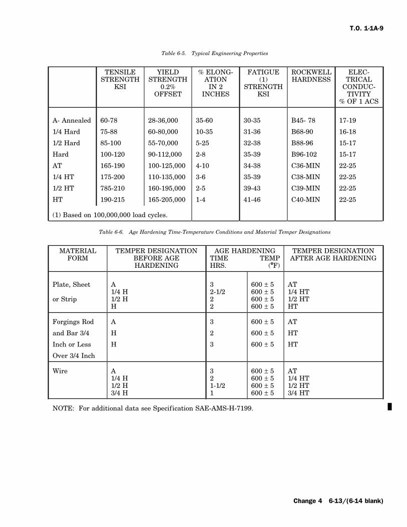
T.O. 1-1A-9
Table 6-5. Typical Engineering Properties
TENSILE YIELD % ELONG- FATIGUE ROCKWELL ELEC-STRENGTH STRENGTH ATION (1) HARDNESS TRICAL
KSI 0.2% IN 2 STRENGTH CONDUC-OFFSET INCHES KSI TIVITY
% OF 1 ACS
A- Annealed 60-78 28-36,000 35-60 30-35 B45- 78 17-19
1/4 Hard 75-88 60-80,000 10-35 31-36 B68-90 16-18
1/2 Hard 85-100 55-70,000 5-25 32-38 B88-96 15-17
Hard 100-120 90-112,000 2-8 35-39 B96-102 15-17
AT 165-190 100-125,000 4-10 34-38 C36-MIN 22-25
1/4 HT 175-200 110-135,000 3-6 35-39 C38-MIN 22-25
1/2 HT 785-210 160-195,000 2-5 39-43 C39-MIN 22-25
HT 190-215 165-205,000 1-4 41-46 C40-MIN 22-25
(1) Based on 100,000,000 load cycles.
Table 6-6. Age Hardening Time-Temperature Conditions and Material Temper Designations
MATERIAL TEMPER DESIGNATION AGE HARDENING TEMPER DESIGNATIONFORM BEFORE AGE TIME TEMP AFTER AGE HARDENING
HARDENING HRS. (oF)
Plate, Sheet A 3 600 ± 5 AT1/4 H 2-1/2 600 ± 5 1/4 HT
or Strip 1/2 H 2 600 ± 5 1/2 HTH 2 600 ± 5 HT
Forgings Rod A 3 600 ± 5 AT
and Bar 3/4 H 2 600 ± 5 HT
Inch or Less H 3 600 ± 5 HT
Over 3/4 Inch
Wire A 3 600 ± 5 AT1/4 H 2 600 ± 5 1/4 HT1/2 H 1-1/2 600 ± 5 1/2 HT3/4 H 1 600 ± 5 3/4 HT
NOTE: For additional data see Specification SAE-AMS-H-7199.
Change 4 6-13/(6-14 blank)

T.O. 1-1A-9
SECTION VII
TOOL STEELS
7-1. GENERAL. acts as an intensifier. It improves the deep hard-ening and elevated temperature properties of steel.7-2. Tool steels are essential to the fabrication of
aircraft parts. It is therefore necessary to provide f. NICKEL - Nickel makes the steel moreguidance in the handling of these important ductile. It is used in only a few applications andmetals. only in small amounts.
7-3. Tool steels are produced and used in a vari- g. SILICON - This element is present in allety of forms. The more common forms are bars, steels. In amounts of 1/4 to 1% it acts as a deoxi-(round, square, hexagonal, or octaganal), drill rods, dizer. Silicon is added to shock resisting and hot(round, square, or rectangular), f lats, and forged work steels to improve their impact characteristicsshapes. and hardenability. It has a graphitizing inf luence
and usually requires the addition of carbide stabi-7-4. ALLOYING ELEMENTS IN TOOL lizing elements such as molybdenum andSTEELS. (See Table 7-2, chemical composition chromium.table.)h. TUNGSTEN - One of the most importanta. CARBON - Carbon is the most important features of tungsten steels is their high red hard-single element in tool steel. Changing the carbon ness. Tungsten steels are fine grained and highcontent a specific amount will change the physical strength, which means they hold good cuttingproperties a greater degree than the same amount edges. Tungsten content is usually 5 - 12% in heatof any other element. Degree of hardness of tool resisting tool steels, 4 - 9% in tungsten - molybde-steel quenched from a suitable temperature is a num high speed steels, and 14 - 20% in straightfunction of carbon content alone. tungsten high speed steel.
b. CHROMIUM - In amounts up to 1.80% the i. VANADIUM - This element forms stableaddition of chromium produced a marked increase carbides and has considerable effect on thein the hardenability (depth of hardness) of steels. hardenability of steels. Undissolved vanadiumSmall amounts of chromium toughens the steel carbides inhibit grain growth and reduce(greater impact strength), and increases its hardenability. Dissolved carbides increasestrength. Machine ability decreases as chromium hardenability. Vanadium is also used as a deoxi-increases. The addition of 5 to 15% chromium dizer. It is added to plain carbon tool steels toimparts hardening qualities to the steel. A degree make them fine grained and tough. It is added toof red hardness and resistance to wear and abra- high speed and hot working steels to resist grainsion results from the addition of chromium to growth and help maintain their hardness at ele-steel. vated temperatures.c. COBALT - Cobalt is sometimes used in 7-5. SPECIFICATIONS. The armed serviceshigh speed tools. Addition of 5 to 8% increase the procure tool steels under three different Federalred hardness of these steels. Specifications, dependent upon its intended use.
Table 7-1 lists these specifications, and presentd. MANGANESE - This element is present inand past classification of the tool steels. Armyall steels. In amounts of less than 1/2%, it acts asSpecification 57-108A was superseded by threea deoxidizer and desulfurizer. In amounts greaterArmy Ordnance Specifications, QQ-S-778, QQ-S-than 15% it gives steel air hardening tendencies.779, and QQ-S-780. which were then supersededIn intermediate amounts it is necessary to haveby Federal Specification’s QQ-T-570, QQ-T-580other alloying agents present with manganeseand QQ-T-590 respectively.because of its tendency to make the steel brittle.
e. MOLYBDENUM - Always used in conjunc-tion with other alloying elements, molybdenum
7-1

T.O. 1-1A-9
D - High carbon-high chromium types
H - Hot work tool steels
T - High speed tool steels
M - Molybdenum Base types
L - Special purpose, low alloy types
F - Carbon tungsten tool steels
Table 7-1. Tool Steel Specifications
SAEDESIGNATION FEDERAL SPECIFICATION SUPERSEDED SPECIFICATION
NUMBER CLASS NUMBER CLASSIFICATION
W1-.80 Carbon QQ-T-580 W1-08 57-108A A1W1-.90 Carbon QQ-T-580 W1-09 57-108A A2W1-1.0 Carbon QQ-T-580 W1-10 57-108A A3W1-1.2 Carbon QQ-T-580 W1-12 57-108A A4/A5W2-.9 Carbon V QQ-T-580 W2-09 57-108A B1W2-1.0 Carbon V QQ-T-580 W2-10 57-108A B1W3-1.0 Carbon VV QQ-T-580 W3-10 QQ-S-00779 (Army) FS-W3-10A2 QQ-T-570 A2 57-108A C1A6 QQ-T-570 A6 ------ ------D2 QQ-T-570 D2 57-108A C2D3 QQ-T-570 D3 57-108A C3D5 QQ-T-570 D5 QQ-S-00778 (Army) FS-D5D7 QQ-T-570 D7 ------ ------F3 QQ-T-570 F3 57-108A D1H11 QQ-T-570 H11 ------ ------H12 QQ-T-570 H12 QQ-S-00778 (Army) FS-H12H13 QQ-T-570 H13 ------ ------H21 QQ-T-570 H21 QQ-S-00778 (Army) FS-H21T1 QQ-T-590 T1 QQ-S-00780 (Army) FS-T1T2 QQ-T-590 T2 QQ-S-00780 (Army) FS-T2T3 QQ-T-590 T3 ------T4 QQ-T-590 T4 QQ-S-00780 (Army) FS-T4T5 QQ-T-590 T5 QQ-S-00780 (Army) FS-T5T6 QQ-T-590 T6 MIL-S-15046 (Ships) T6T7 QQ-T-590 T7 QQ-S-00780 (Army) FS-T7T8 QQ-T-590 T8 QQ-S-00780 (Army) FS-T8M1 QQ-T-590 M1 QQ-S-00780 (Army) FS-M1M2 QQ-T-590 M2 QQ-S-00780 (Army) FS-M2M3 QQ-T-590 M3 QQ-S-00780 (Army) FS-M3M4 QQ-T-590 M4 ------ ------M10 QQ-T-590 M-10 57-108A F1M15 QQ-T-590 M15 ------ ------M30 QQ-T-590 M30 57-108A F3M34 QQ-T-590 M34 QQ-S-00780 (Army) FS-M3401 QQ-T-570 01 57-108A.QQ-T-778 B402 QQ-T-570 02 57-108A B306 QQ-T-570 06 ------ ------L6 QQ-T-570 L6 ------ ------L7 QQ-T-570 L7 QQ-S-00778 (Army) FS-L7T15 QQ-T-590 T15 ------ ------S1 QQ-T-570 S1 QQ-S-00778 (Army) FS-S1S2 QQ-T-570 S2 QQ-S-00778 (Army) FS-S2S5 QQ-T-570 S5 QQ-S-00778 (Army) FS-S5W5 QQ-T-570 W5 QQ-S-00778 (Army) FS-W5
7-2
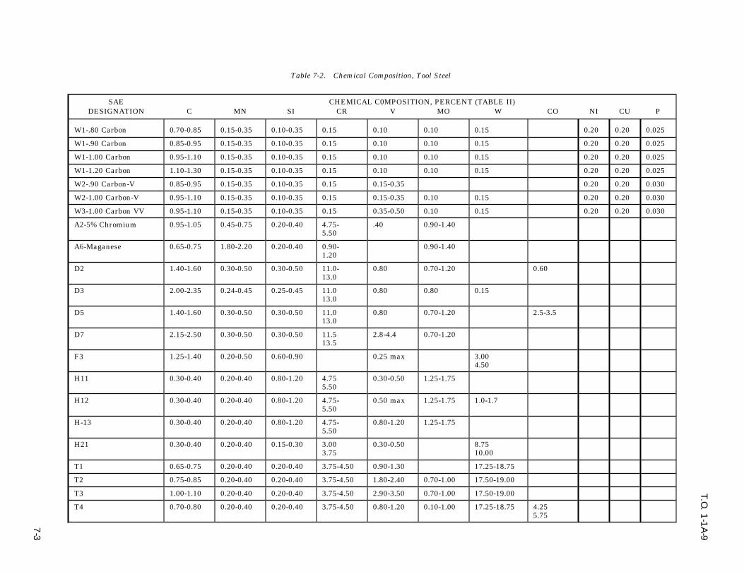
T.O. 1
-1A
-9
7-3
Table 7-2. Chemical Composition, Tool Steel
SAE CHEMICAL C0MPOSITION, PERCENT (TABLE II)DESIGNATION C MN SI CR V MO W CO NI CU P
W1-.80 Carbon 0.70-0.85 0.15-0.35 0.10-0.35 0.15 0.10 0.10 0.15 0.20 0.20 0.025
W1-.90 Carbon 0.85-0.95 0.15-0.35 0.10-0.35 0.15 0.10 0.10 0.15 0.20 0.20 0.025
W1-1.00 Carbon 0.95-1.10 0.15-0.35 0.10-0.35 0.15 0.10 0.10 0.15 0.20 0.20 0.025
W1-1.20 Carbon 1.10-1.30 0.15-0.35 0.10-0.35 0.15 0.10 0.10 0.15 0.20 0.20 0.025
W2-.90 Carbon-V 0.85-0.95 0.15-0.35 0.10-0.35 0.15 0.15-0.35 0.20 0.20 0.030
W2-1.00 Carbon-V 0.95-1.10 0.15-0.35 0.10-0.35 0.15 0.15-0.35 0.10 0.15 0.20 0.20 0.030
W3-1.00 Carbon VV 0.95-1.10 0.15-0.35 0.10-0.35 0.15 0.35-0.50 0.10 0.15 0.20 0.20 0.030
A2-5% Chromium 0.95-1.05 0.45-0.75 0.20-0.40 4.75- .40 0.90-1.405.50
A6-Maganese 0.65-0.75 1.80-2.20 0.20-0.40 0.90- 0.90-1.401.20
D2 1.40-1.60 0.30-0.50 0.30-0.50 11.0- 0.80 0.70-1.20 0.6013.0
D3 2.00-2.35 0.24-0.45 0.25-0.45 11.0 0.80 0.80 0.1513.0
D5 1.40-1.60 0.30-0.50 0.30-0.50 11.0 0.80 0.70-1.20 2.5-3.513.0
D7 2.15-2.50 0.30-0.50 0.30-0.50 11.5 2.8-4.4 0.70-1.2013.5
F3 1.25-1.40 0.20-0.50 0.60-0.90 0.25 max 3.004.50
H11 0.30-0.40 0.20-0.40 0.80-1.20 4.75 0.30-0.50 1.25-1.755.50
H12 0.30-0.40 0.20-0.40 0.80-1.20 4.75- 0.50 max 1.25-1.75 1.0-1.75.50
H-13 0.30-0.40 0.20-0.40 0.80-1.20 4.75- 0.80-1.20 1.25-1.755.50
H21 0.30-0.40 0.20-0.40 0.15-0.30 3.00 0.30-0.50 8.753.75 10.00
T1 0.65-0.75 0.20-0.40 0.20-0.40 3.75-4.50 0.90-1.30 17.25-18.75
T2 0.75-0.85 0.20-0.40 0.20-0.40 3.75-4.50 1.80-2.40 0.70-1.00 17.50-19.00
T3 1.00-1.10 0.20-0.40 0.20-0.40 3.75-4.50 2.90-3.50 0.70-1.00 17.50-19.00
T4 0.70-0.80 0.20-0.40 0.20-0.40 3.75-4.50 0.80-1.20 0.10-1.00 17.25-18.75 4.255.75

T.O. 1
-1A
-9
7-4 Table 7-2. Chemical Composition, Tool Steel - Continued
SAE CHEMICAL C0MPOSITION, PERCENT (TABLE II)DESIGNATION C MN SI CR V MO W CO NI CU P
T5 0.75-0.85 0.20-0.40 0.20-0.40 3.75-4.75 1.80-2.40 0.70-1.00 17.50-19.00 7.009.50
T6 0.75-0.85 0.20-0.40 0.20-0.40 4.00-4.75 1.50-2.10 0.70-1.00 18.50-21.25 10.2513.75
T7 0.70-0.76 0.20-0.40 0.20-0.40 3.75-4.25 1.80-2.20 0.70-1.00 13.50-14.50T8 0.75-0.85 0.20-0.40 0.20-0.40 3.75-4.50 1.80-2.40 0.70-1.00 13.25-14.75 4.25-
5.75
M1 0.75-0.85 0.20-0.40 0.20-0.40 3.75-4.50 0.90-1.30 7.75-9.25 1.15-1.85
M2 0.78-0.88 0.20-0.40 0.20-0.40 3.75-4.50 1.60-2.20 4.50-5.50 5.50-6.75
M3 1.00-1.25 0.20-0.40 0.20-0.40 3.75-4.50 2.35-3.25 4.75-6.25 5.50-6.75
M4 1.25-1.40 0.20-0.40 0.20-0.40 4.00-4.75 3.90-4.50 4.50-5.50 5.25-6.50
M10 0.85-0.95 0.20-0.40 0.20-0.40 3.75-4.50 1.80-2.20 7.75-9.00
M15 1.50-1.60 0.20-0.40 0.20-0.40 4.00-5.00 4.50-5.25 2.75-3.50 6.00-6.75 4.75-5.25
M30 0.77-0.85 0.20-0.40 0.20-0.40 3.50-4.25 1.00-1.40 7.75-9.00 1.30-2.30 4.50-5.50
M34 0.85-0.92 0.20-0.30 0.20-0.30 3.50-4.25 1.90-2.30 8.00-9.20 1.30-2.30 1.758.75
01 0.85-0.95 1.00-1.30 0.20-0.40 0.40-0.60 0.30 max 0.40-0.60
02 0.85-0.95 1.40-1.80 0.20-0.40 0.35 0.20 0.30
06 1.35-1.55 0.30-1.00 0.80-1.20 0.20-0.30
L6 0.65-0.75 0.30-0.80 0.20-0.40 0.65-0.85 0.20-0.35 0.20-0.35 1.251.75
L7 0.95-1.05 0.25-0.45 0.20-0.40 1.25-1.75 0.30-0.50T15 1.50-1.60 3.75-4.50 4.75-5.25 12.00-13.00 4.75-5.25
S1 0.45-0.55 0.20-0.40 0.25-0.45 1.25-1.75 0.15-0.30 0.40 1.0-3.0
S2 0.45-0.55 0.30-0.50 0.80-1.20 0.25 0.40-0.60
S5 0.50-0.60 0.60-0.90 1.80-2.20 0.30 0.25 0.30-0.50
W5 1.05-1.25 0.15-0.35 0.10-0.40 0.40-0.60 0.25 max 0.30-0.50

T.O. 1-1A-9
Table 7-3. Tool Steel Selection
MATERIAL TO BE CUT TOTAL QUANTITY OF PARTS TO BE MADE1,000 10,000 100,000
Aluminum, copper and magnesium alloys W1, AIS14140 W1, 01, A2 01, A2
Carbon and alloy steels, ferritic stainless W1, AIS14140 W1, 01, A2 01, A2
Stainless steel, austenitic W1, A2 W1, A2, D2 A2, D2
Spring steel, hardened, Rockwell C52max A2 A2, D2 D2
Electrical sheet, transformer grade A2 A2, D2 D2
Paper, gaskets, and similar soft material W1 W1 W1, A2
Plastic sheet, not reinforced 01 01 01, A2
Table 7-3 is listed for use as a guide reference in the selection of tool steel types for specificapplications.
Table 7-4. Tool Steel Hardening and Tempering Temperatures
STEEL HARDENING TEMPERING SIZE CHANGE, IN/INTREATMENT TREATMENT
W 1450oF, Water 300oF 0.0017 - 0.0025
O 1450oF, Oil 300oF 0.0014 - 0.0021
L 1550oF, Oil 300oF 0.0014 - 0.0024
F 1600oF, Oil 300oF 0.0011 - 0.0021
S 1750oF, Oil 500oF 0.0010 - 0.0025
A 1775oF, Oil 500oF 0.0005 - 0.0015
D 1875oF, Oil 500oF 0.0005 - 0.0005
T 2350oF, Oil 1050oF 0.0006 - 0.0014
M 2225oF, Oil 1025oF 0.0016 - 0.0024
7-6. CLASS DESIGNATIONS. cutting tools require high hardness, high resis-tance to the softening effect of heat, and high
W - Water hardening tool steels wear resistance. Shearing tools require high wearresistance and fair toughness. Forming tools mustS - Shock resisting tool steelspossess high wear resistance or high toughness
O - Cold work tool steels, oil hardening types and strength. In battering tools, high toughness ismost important.A - Cold work tool steels, air hardening types7-9. SELECTION OF MATERIAL FOR A CUT-7-7. APPLICATIONS OF TOOL STEELS.TING TOOL. The selection of material for a cut-
7-8. The majority of tool steel applications can be ting tool depends on several factors: the metaldivided into a small number of groups: cutting, being machined, nature of cutting operation, condi-shearing, forming, drawing, extrusion, rolling and tion of the machine tool, machining practice, sizebattering. Cutting tools include drills, taps, and design of tool, coolant to be used, and cost ofbroaches, hobs, lathe tools, etc. Shearing tools tool material. Selection is usually based more oninclude shears, blanking and trimming dies, previous experience or applications than on anpunches, etc. Forming tools include draw, forging, engineering or metallurgical analysis.cold heading and die casting dies. Battering toolsinclude chisels and all forms of shock tools. Most
7-5

T.O. 1-1A-9
NOTE7-10. High speed cutting tools are usually manu-factured from the class ‘‘T’’ or class ‘‘M’’ alloys. Additional Heat Treatment informa-Four classes, T1, M1, M2 and M10 make up nearly tion is discussed in Section IX.90% of the general purpose high speed steels. Cer-tain special purpose steels in each class, such as 7-17. The thermal treatments listed in table 7-5T6, T7, T8 and T15 are advantageous for opera- cover the generally used treatments for the forg-tions like milling cutters and prehardened forging ings, normalizing, and annealing of tool and diedie blocks. steels. The thermal treatments listed in table 7-7
cover the usual ranges of temperatures for harden-7-11. High speed drills should possess highing and tempering tool and die steels. Thesestrength and toughness, notably M1, M2, M10 andtables are listed for use as a guide only, and testT1. Classes T1 and M1 are used for tools subjectsamples should be checked prior to use.to shock, while M2 and M10 are generally used
where tools require less toughness and more abra-7-18. DISTORTION IN TOOL STEELS. Distor-sion resistance.tion is a general term encompassing all dimen-
7-12. Material for reamers should be of high sional changes; the two main types being volumehardness and abrasion resistance, such as M1, M2, change or change in geometrical form. VolumeM10 and T1. The M3 and M15 and T15 classes change is defined as expansion or contraction andpossess greater abrasion resistance than the lower- geometric change is defined as changes in curva-vanadium grades. ture or angular relations. Table 7-4 shows an
approximate range of size changes depending upon7-13. Material for taps is generally of the M1,the type of tool steel, and also dependent on spe-M2 or M10 types. In tapping heat-resisting alloyscific tempering and heat treatments. If a veryor steels harder than Rockwell C35, M15 or T15close tolerance is required for a f inished tool, spe-may be justified.cif ic data covering this item should be obtained
7-14. Milling cutters are usually made from the from a detailed source.high speed steels. As the hardness of theworkpiece increases beyond Rockwell C35, the 7-19. Deletedcobalt high speed steels should be used.
7-20. Deleted7-15. Recommended punch and die material forblanking parts from 0.050 inch sheet materials are 7-21. Deletedshown in following table. This table does not coverall operations, and is a sample table intended for 7-22. Deleteduse as a guide only.
7-16. HEAT TREAT DATA. 7-23. Deleted
7-6 Change 1

T.O. 1
-1A
-9
Change 1
7-7
Table 7-5. Forging, Normalizing and Annealing Treatments of Tool and Die Steels
FORGING/a NORMALIZING/b ANNEALING/c
SAE HEAT START DO NOT HEAT HOLD AT TEMPER- MAX RATE BRINELLDESIGNA- SLOWLY FORGING FORGE SLOWLY ATURE OF COOL- HARDNESS ROCKWELL
TION TO AT BELOW TO ING F/HR APPROX. B, APPROX.
W1 (0.8C) 1450 1800 1500 1450 1500 1400-1450 75 159-202 84-941950
W1 (0.9C) 1450 1800 1500 1450 1500 1375-1425 75 159-202 84-941950
W1 (1.0C) 1450 1800 1500 1450 1550 1400-1450 75 159-202 84-941900
W1 (1.2C) 1450 1800 1500 1450 1625 1400-1450 75 159-202 84-941900
W2 (0.9C) 1450 1800 1500 1450 1500 1375-1425 75 159-202 84-941900
W2 (1.0C) 1450 1800 1500 1450 1550 1400-1450 75 159-202 84-941900
W3 (1.0C) 1450 1800 1500 1450 1550 1400-1450 75 159-202 84-941900
A2 1600 1850 1650 DO NOT NORMALIZE 1550-1600 40 202-229 94-982000
A6 1200-1300 DO NOT NORMALIZE 248 102
D2 1650 1850 1650 DO NOT NORMALIZE 1600-1650 40 207-255 95-1022000
D3 1650 1850 1650 DO NOT NORMALIZE 1600-1650 50 212-255 96-1022000
D5 1650 1850 1650 DO NOT NORMALIZE 1600-1650 40 207-255 95-1022000
D7 1650 2050 1800 DO NOT NORMALIZE 1600-1650 50 235-262 99-1032125
F3 1550 1800 1600 DO NOT NORMALIZE 1475 50 235 992000

T.O. 1
-1A
-9
7-8
Change 1
Table 7-5. Forging, Normalizing and Annealing Treatments of Tool and Die Steels - Continued
FORGING/a NORMALIZING/b ANNEALING/c
SAE HEAT START DO NOT HEAT HOLD AT TEMPER- MAX RATE BRINELLDESIGNA- SLOWLY FORGING FORGE SLOWLY ATURE OF COOL- HARDNESS ROCKWELL
TION TO AT BELOW TO ING F/HR APPROX. B, APPROX.
H11 1650 1950 1650 DO NOT NORMALIZE 1550-1600 50 192-229 92-982100
H12 1650 1950 1650 DO NOT NORMALIZE 1600-1650 50 192-229 92-982100
H13 1650 1950 1650 DO NOT NORMALIZE 1550-1600 50 192-229 92-982100
H21 1600 2000 1650 DO NOT NORMALIZE 1600-1650 50 202-235 94-992150
T1 1600 1950 1750 DO NOT NORMALIZE 1600-1650 50 217-255 96-1022100
T2 1600 2000 1750 DO NOT NORMALIZE 1600-1650 50 223-255 97-1022150
T3 1925 2025 1750 DO NOT NORMALIZE 1650 50
T4 1600 2000 1750 DO NOT NORMALIZE 1600-1650 50 229-255 98-1022150
T5 1600 2000 1800 DO NOT NORMALIZE 1600-1650 50 248-293 102-1062150
T6 1600 1950 1700 DO NOT NORMALIZE 1600-1650 50 248-293 102-1062150
T7 1600 1950 1700 DO NOT NORMALIZE 1550-1625 50 217-250 96-1022150
T8 1600 2000 1750 DO NOT NORMALIZE 1600-1650 50 229-255 98-1022150
M1 1500 1900 1700 DO NOT NORMALIZE 1525-1600 50 207-248 95-1022050
M2 1500 1950 1700 DO NOT NORMALIZE 1550-1625 50 217-248 96-1022100
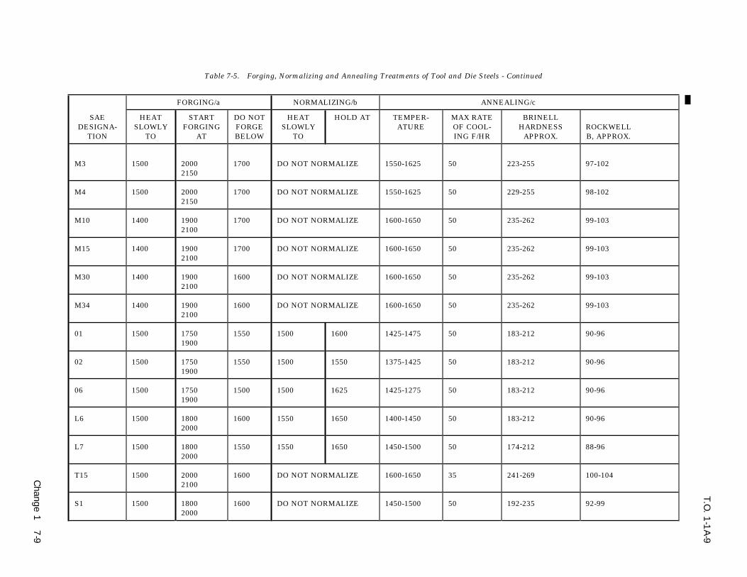
T.O. 1
-1A
-9
Change 1
7-9
Table 7-5. Forging, Normalizing and Annealing Treatments of Tool and Die Steels - Continued
FORGING/a NORMALIZING/b ANNEALING/c
SAE HEAT START DO NOT HEAT HOLD AT TEMPER- MAX RATE BRINELLDESIGNA- SLOWLY FORGING FORGE SLOWLY ATURE OF COOL- HARDNESS ROCKWELL
TION TO AT BELOW TO ING F/HR APPROX. B, APPROX.
M3 1500 2000 1700 DO NOT NORMALIZE 1550-1625 50 223-255 97-1022150
M4 1500 2000 1700 DO NOT NORMALIZE 1550-1625 50 229-255 98-1022150
M10 1400 1900 1700 DO NOT NORMALIZE 1600-1650 50 235-262 99-1032100
M15 1400 1900 1700 DO NOT NORMALIZE 1600-1650 50 235-262 99-1032100
M30 1400 1900 1600 DO NOT NORMALIZE 1600-1650 50 235-262 99-1032100
M34 1400 1900 1600 DO NOT NORMALIZE 1600-1650 50 235-262 99-1032100
01 1500 1750 1550 1500 1600 1425-1475 50 183-212 90-961900
02 1500 1750 1550 1500 1550 1375-1425 50 183-212 90-961900
06 1500 1750 1500 1500 1625 1425-1275 50 183-212 90-961900
L6 1500 1800 1600 1550 1650 1400-1450 50 183-212 90-962000
L7 1500 1800 1550 1550 1650 1450-1500 50 174-212 88-962000
T15 1500 2000 1600 DO NOT NORMALIZE 1600-1650 35 241-269 100-1042100
S1 1500 1800 1600 DO NOT NORMALIZE 1450-1500 50 192-235 92-992000

T.O. 1
-1A
-9
7-1
0C
hange 1
Table 7-5. Forging, Normalizing and Annealing Treatments of Tool and Die Steels - Continued
FORGING/a NORMALIZING/b ANNEALING/c
SAE HEAT START DO NOT HEAT HOLD AT TEMPER- MAX RATE BRINELLDESIGNA- SLOWLY FORGING FORGE SLOWLY ATURE OF COOL- HARDNESS ROCKWELL
TION TO AT BELOW TO ING F/HR APPROX. B, APPROX.
S2 1500 1900 1600 1500- 1650 1400-1450 50 192-229 92-982100
S5 1500 1900 1600 1500 1600 1400-1450 50 192-229 92-982050
W5 1200 1700 1500 DO NOT NORMALIZE 1400-1425 50 192-212 92-961900
a. The temperature at which to start forging is given as a range, the higher side of which should be used for large sections and heavy or rapid reductions,and the lower side for smaller sections and lighter reductions, as the alloy content of the steel increases, the time of soaking at forging temperatureincreases proportionately. Likewise, as the alloy content increases, it becomes more necessary to cool slowly from the forging temperature. With the veryhigh alloy steels, such as high speed or air hardening steels, this slow cooling is imperative in order to prevent cracking and to leave the steel in a semi-softcondition. Either furnace cooling or burying in an insulating medium such as lime, mica, or silocel is satisfactory.
b. The length of time the steel is held after being uniformly heated through at the normalizing temperature, varies from about 15 minutes for a smallsection to about 1 hour for larger sizes. Cooling from the normalizing temperatures is done in still air. The purpose of normalizing after forging is to refinethe grain structure and to produce a uniform structure throughout the forging. Normalizing should not be confused with low temperature (about 1200F)annealing used for the relief of redisual stresses resulting from heavy machining, bending and forming.
c. The annealing temperature is given as a range, the upper limit of which should be used for large sections, and the lower limit for smaller sections. Thetemperature varies from about 1 hour for light sections and small furnace charges of carbon or low alloy steel, to about 4 hours for heavy sections and largefurnace charges of high alloy steel.
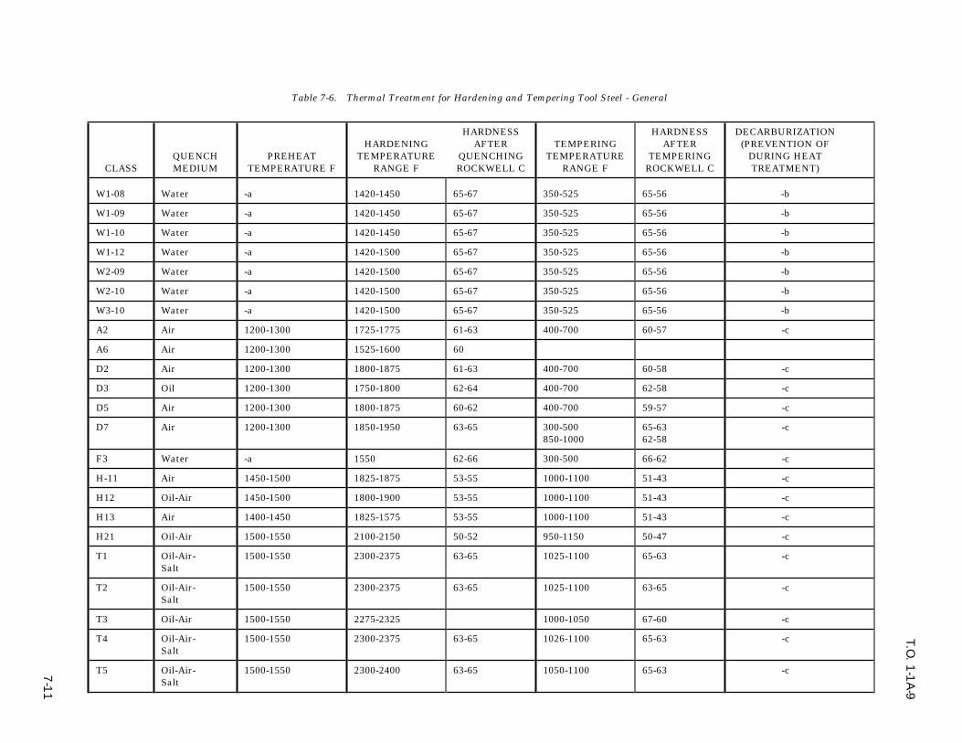
T.O. 1
-1A
-9
7-1
1
Table 7-6. Thermal Treatment for Hardening and Tempering Tool Steel - General
HARDNESS HARDNESS DECARBURIZATIONHARDENING AFTER TEMPERING AFTER (PREVENTION OF
QUENCH PREHEAT TEMPERATURE QUENCHING TEMPERATURE TEMPERING DURING HEATCLASS MEDIUM TEMPERATURE F RANGE F ROCKWELL C RANGE F ROCKWELL C TREATMENT)
W1-08 Water -a 1420-1450 65-67 350-525 65-56 -b
W1-09 Water -a 1420-1450 65-67 350-525 65-56 -b
W1-10 Water -a 1420-1450 65-67 350-525 65-56 -b
W1-12 Water -a 1420-1500 65-67 350-525 65-56 -b
W2-09 Water -a 1420-1500 65-67 350-525 65-56 -b
W2-10 Water -a 1420-1500 65-67 350-525 65-56 -b
W3-10 Water -a 1420-1500 65-67 350-525 65-56 -b
A2 Air 1200-1300 1725-1775 61-63 400-700 60-57 -c
A6 Air 1200-1300 1525-1600 60
D2 Air 1200-1300 1800-1875 61-63 400-700 60-58 -c
D3 Oil 1200-1300 1750-1800 62-64 400-700 62-58 -c
D5 Air 1200-1300 1800-1875 60-62 400-700 59-57 -c
D7 Air 1200-1300 1850-1950 63-65 300-500 65-63 -c850-1000 62-58
F3 Water -a 1550 62-66 300-500 66-62 -c
H-11 Air 1450-1500 1825-1875 53-55 1000-1100 51-43 -c
H12 Oil-Air 1450-1500 1800-1900 53-55 1000-1100 51-43 -c
H13 Air 1400-1450 1825-1575 53-55 1000-1100 51-43 -c
H21 Oil-Air 1500-1550 2100-2150 50-52 950-1150 50-47 -c
T1 Oil-Air- 1500-1550 2300-2375 63-65 1025-1100 65-63 -cSalt
T2 Oil-Air- 1500-1550 2300-2375 63-65 1025-1100 63-65 -cSalt
T3 Oil-Air 1500-1550 2275-2325 1000-1050 67-60 -c
T4 Oil-Air- 1500-1550 2300-2375 63-65 1026-1100 65-63 -cSalt
T5 Oil-Air- 1500-1550 2300-2400 63-65 1050-1100 65-63 -cSalt
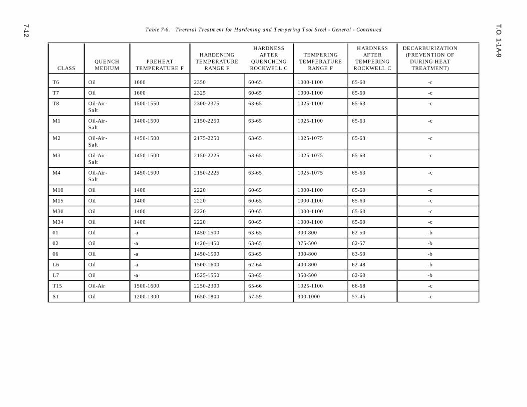
T.O. 1
-1A
-9
7-1
2 Table 7-6. Thermal Treatment for Hardening and Tempering Tool Steel - General - Continued
HARDNESS HARDNESS DECARBURIZATIONHARDENING AFTER TEMPERING AFTER (PREVENTION OF
QUENCH PREHEAT TEMPERATURE QUENCHING TEMPERATURE TEMPERING DURING HEATCLASS MEDIUM TEMPERATURE F RANGE F ROCKWELL C RANGE F ROCKWELL C TREATMENT)
T6 Oil 1600 2350 60-65 1000-1100 65-60 -c
T7 Oil 1600 2325 60-65 1000-1100 65-60 -c
T8 Oil-Air- 1500-1550 2300-2375 63-65 1025-1100 65-63 -cSalt
M1 Oil-Air- 1400-1500 2150-2250 63-65 1025-1100 65-63 -cSalt
M2 Oil-Air- 1450-1500 2175-2250 63-65 1025-1075 65-63 -cSalt
M3 Oil-Air- 1450-1500 2150-2225 63-65 1025-1075 65-63 -cSalt
M4 Oil-Air- 1450-1500 2150-2225 63-65 1025-1075 65-63 -cSalt
M10 Oil 1400 2220 60-65 1000-1100 65-60 -c
M15 Oil 1400 2220 60-65 1000-1100 65-60 -c
M30 Oil 1400 2220 60-65 1000-1100 65-60 -c
M34 Oil 1400 2220 60-65 1000-1100 65-60 -c
01 Oil -a 1450-1500 63-65 300-800 62-50 -b
02 Oil -a 1420-1450 63-65 375-500 62-57 -b
06 Oil -a 1450-1500 63-65 300-800 63-50 -b
L6 Oil -a 1500-1600 62-64 400-800 62-48 -b
L7 Oil -a 1525-1550 63-65 350-500 62-60 -b
T15 Oil-Air 1500-1600 2250-2300 65-66 1025-1100 66-68 -c
S1 Oil 1200-1300 1650-1800 57-59 300-1000 57-45 -c

T.O. 1
-1A
-9
7-1
3
Table 7-6. Thermal Treatment for Hardening and Tempering Tool Steel - General - Continued
HARDNESS HARDNESS DECARBURIZATIONHARDENING AFTER TEMPERING AFTER (PREVENTION OF
QUENCH PREHEAT TEMPERATURE QUENCHING TEMPERATURE TEMPERING DURING HEATCLASS MEDIUM TEMPERATURE F RANGE F ROCKWELL C RANGE F ROCKWELL C TREATMENT)
S2 Water-oil -A 1550-1575 60-62 300-500 60-54 -b1660-1625 58-60 300-500 58-54 -b
S5 Water 1550-1600 60-62 300-650 60-54 -b
Oil 1600-1675 58-60 300-650 58-54 -b
W5 Water 1100-1200 1400-1550 65-66 300-400 62-65 -b
a. For large tools and tools having intricate sections, preheating at 1050o to 1200o is recommended.
b. Use moderately oxidizing atmosphere in furnace or a suitable neutral salt bath.
c. Use protective pack from which volatile matter has been removed, carefully balanced neutral salt bath or atmosphere controlled furnaces. In the latter case, thefurnace atmosphere should be in equilibrium with the carbon content of the steel being treated. Furnace atmosphere dew point is considered a reliable method ofmeasuring and controlling this equilibrium.

T.O. 1-1A-9
Table 7-7. Comparison of Tool Steel Properties
NON RESISTANCEDEFORMING TO SOFTENING WEAR MACHINE
CLASS PROPERTIES TOUGHNESS EFFECT OF RESISTANCE ABILITYHEAT
W1-08 Poor Good Poor Fair Best
W1-09 Poor Good Poor Fair Best
W1-10 Poor Good Poor Good Best
W1-12 Poor Good Poor Good Best
W2-09 Poor Good Poor Fair Best
W2-10 Poor Good Poor Good Best
W3-10 Poor Good Poor Good Best
A2 Best Fair Fair Good Fair
A6 Good Fair Poor Good Fair
D2 Best Fair Fair Best Poor
D3 Good Poor Fair Best Poor
D5 Best Fair Fair Best Poor
D7 Best Poor Fair Best Poor
F3 Poor Poor Poor Best Fair
H11 Good Good Good Fair Fair
Hl2 Good Good Good Fair Fair
Hl3 Good Good Good Fair Fair
H21 Good Good Good Fair Fair
T1 Good Poor Good Good Fair
T2 Good Poor Good Good Fair
T3 Good Poor Good Good Fair
T4 Good Poor Best Good Fair
T5 Good Poor Best Good Fair
T6 Good Fair Good Best Fair
T7 Good Poor Good Best Fair
T8 Good Poor Best Good Fair
M1 Good Poor Good Good Fair
M2 Good Poor Good Good Fair
M3 Good Poor Good Best Fair
M4 Good Poor Good Best Fair
M10 Good Poor Good Best Fair
M15 Good Poor Good Best Fair
M30 Good Poor Good Best Fair
M34 Good Poor Good Best Fair
01 Good Fair Poor Good Good
7-14

T.O. 1-1A-9
Table 7-7. Comparison of Tool Steel Properties - Continued
NON RESISTANCEDEFORMING TO SOFTENING WEAR MACHINE
CLASS PROPERTIES TOUGHNESS EFFECT OF RESISTANCE ABILITYHEAT
02 Good Fair Poor Good Good
06 Fair Fair Poor Good Best
L6 Fair Fair Poor Fair Fair
L7 Fair Fair Poor Good Fair
T15 Good Poor Best Best Fair
S1 Fair Good Fair Fair Fair
S2 W-Poor Best Fair Fair GoodO-Fair
S5 W-Poor Good Poor Fair BestO-Fair
W5 Poor Good Poor Fair Best
7-15/(7-16 blank)


T.O. 1-1A-9
SECTION VIII
TESTING AND INSPECTION
HARDNESS TESTING
8-1. GENERAL. d. A release mechanism with micrometer eye-piece for calculating the area of the impression.
8-2. Hardness testing is used to determine theresults of heat treatment as well as the state of 8-7. Making The Brinell Test. The test isthe metal prior to heat treatment. Its application preformed as follows:in determining the approximate tensile strength of
a. Prepare the sample by filing, grinding, andthe material by use of a hardness-tensile strengthpolishing to remove all scratches and variationstable is very limited and should only be used inthat may affect the reading.the case of ferrous (steel) alloys. Table 8-1 should
be used only as a conversion table for converting b. Place the sample on the anvil of thethe various hardness values from one type of test machine and elevate until the hardened ball con-to another, and should not be used as an indica- tacts the surface to be tested.tion of tensile strength for alloys other than fer-
c. Apply the load by pumping handle.rous. In addition, it should be realized that valuesgiven in Table 8-1 are only approximate. When- NOTEever a specific type of hardness test is given in a
A load of 3,000 kilograms is requireddrawing, specification, etc., necessary hardnessfor steel, while 500 kilograms is usedreadings should be made by that test wheneverwhen testing the softer metals, suchpossible, rather than by other means, and a con-as aluminum alloy, brass, and bronze.version made. In obtaining hardness values, pre-Normally, the load should be appliedcaution must be taken to assure removal of clad-for 30 seconds. Although this periodding and decarburized surface layers from area tomay be increased to 1 minute forbe tested.extremely hard steels, in order to pro-
8-3. METHODS OF HARDNESS TESTING. duce equilibrium.
d. Release the pressure and measure the area8-4. The methods of hardness testing in generalof impression with the calibrated microscope.use are: Brinell, Rockwell, Vickers (British), Tukon
and Shore scleroscope. e. Calculate the Brinell number, completingthe test.8-5. BRINELL HARDNESS TEST. This test
consists of pressing a hardened steel ball into a8-8. ROCKWELL HARDNESS TEST. Thef lat surface of the metal being tested by the appli-Rockwell hardness test is based on the degree ofcation of a known pressure. The impression madepenetration of a specifically designed indentor intoby the ball is measured by means of a microscopea material under a given static load. Thewith a micrometer eyepiece. The Brinell ‘‘number’’indentor/penetrator used may be either a diamondis obtained by dividing the load in kilograms byor hardened steel ball. The diamond indentorthe area of the spherical impression made by thecalled a ‘‘brale’’ is precision ground and polishedball, measured in square millimeters. The thick-and the shape is spheroconica. The steel ball forness of all samples used for testing must be suffi-normal use is 1/16 inch diameter, however, othercient to prevent bulging on the under side.larger diameter steel balls such as 1/8, 1/4 or 1/2inch may be used for testing soft metals. The8-6. Brinell Tester. The Brinell tester (Figure 8-selection of the ball is based on the hardness range1) consists of the following major parts:of the type of materia1 to be tested.
a. An elevating screw and anvil for bringingthe sample into contact with the ball. 8-9. The Rockwell machine/tester for accomplish-
ing the hardness test applies two loads to obtainb. A manually operated hydraulic pump for the controlled penetration and indicates results onapplying the pressure to the hardened steel ball, a graduated dial (see Figure 8-2). A minor load ofwhich is mounted on its actuating member. 10 kilograms is f irst applied to seat the penetratorc. A pressure gage for determining the in the surface of the test specimen. The actual
applied pressure. penetration is then produced by applying a major
8-1
T.O. 1-1A-9
load, subsequently, releasing and then reading c. Check trip lever for proper location. Leverhardness number from the dial. The dial reading should be located in the OFF LOAD position.is related to the depth of penetration, load and the d. Place the test specimen on the anvil and bypenetrator used. The shallower the penetration, turning the hand wheel, raise it slowly (do notthe higher the hardness value number for given crash) until contact is made with the penetrator.indentor and load. The normal major load is 150 On the older model continue turning until pointerkilograms (‘‘C’’ Scale) when using the diamond of the indicator has made three revolutions and ispenetrator and 100 kilograms (‘‘B’’Scale) when within five divisions (plus or minus) of the uprightusing a 1/16 inch steel ball. A hardness value indi- position. On the newer model after contact, con-cated by a number alone is incomplete. The num- tinue turning hand wheel until the small pointerber must be prefixed with a letter to indicate the is nearly vertical and slightly to right of the dot.load and indentor used to obtain the number. Then watching the long pointer, raise specimenThere is a variety of combinations of indentors and until long pointer is approximately upright withinloads used to obtain a hardness value in accor- three degrees (plus or minus) of C-0. K the C=+3dance with hardness range of various material. degrees position is overshot, lower the specimenThe combinations are listed in Table 8-2 which is and start over. When the pointer is within threebased on Specification ASTM E-18. divisions of C-0, set dial to zero. After this step is8-10. Review of Table 8-2 will reveal that the complete, the minor load has been applied.Red Dial Numerals ‘‘B’’ scale are used for steel ball e. Apply the major load by tripping the tripindentors regardless of size of ball or load and lever. Trip the lever, do not push.Black Figure ‘‘C’’ scales are used for the diamondpenetrator. When the readings fall below the f. When the trip lever comes to rest and therehardness value, C20 (B98) the material is consid- is no further movement of pointer, return lever toered too soft for the diamond cone and 1/16 inch or the original position and read the hardness num-larger hardened ball should be used. The diamond ber indicated by the dial. When dial pointer indi-cone must be used for all hard materials (those cates a fraction, use next lower whole number forabove 100 on the ‘‘B’’scale) as the steel ball may be the reading.deformed by the test. If in doubt about the hard-
8-12. All hardness tests should be made on aness of a material start with the diamond pene-single thickness to obtain accurate results. Intrator and switch to the steel ball if the material istesting curved specimens, the concave side shouldbelow C20-C22.face the indentor; if reversed, an inaccurate read-
8-11. Rockwell Test Procedure: The procedure for ing will result due to f latening of the piece on themaking the Rockwell test is outlined as follows: anvil. Specimens that do not balance on the anvil(See Figure 8-2 for machine illustrations.) because of overhang should be properly supported
to obtain accurate readings and to prevent damag-a. Prepare the sample by removing (f ile, grinding the penetrator. Also to obtain a true indica-and polish) scale, oxide films, pits, variations andtion of hardness of a given part, several readingsforeign material that may affect the reading. The(3-6 is usually sufficient) at different points shouldsurface should be f lat, of one thickness and nobe taken and averaged. If it is necessary to deter-bludge should be opposite the indentation.mine the condition of the interior, parts should becut by some method that does not appreciablyNOTEchange the temper/ condition, such as using aDo not perform test closer than 1/8″ water-cooled saw-off wheel. When testing cladfrom edge of specimen to assure accu- material; the clad coat shall be removed. Speci-rate reading. men samples of clad and other materials should be
b. Select the proper anvil and penetrator and provided when possible. It is not desirable toplace proper weight on the weight pan. accomplish the test on the finished part.
8-2

T.O. 1-1A-9
Table 8-1. Hardness Conversion Chart
8-3
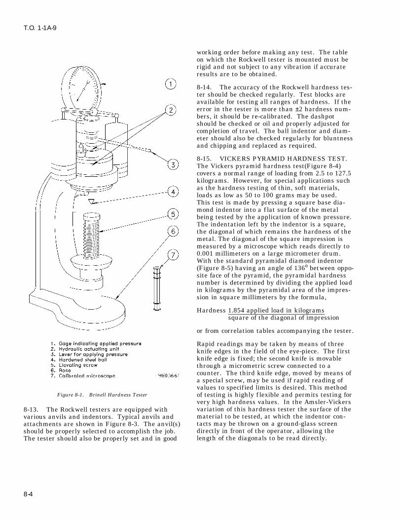
T.O. 1-1A-9
working order before making any test. The tableon which the Rockwell tester is mounted must berigid and not subject to any vibration if accurateresults are to be obtained.
8-14. The accuracy of the Rockwell hardness tes-ter should be checked regularly. Test blocks areavailable for testing all ranges of hardness. If theerror in the tester is more than ±2 hardness num-bers, it should be re-calibrated. The dashpotshould be checked or oil and properly adjusted forcompletion of travel. The ball indentor and diam-eter should also be checked regularly for bluntnessand chipping and replaced as required.
8-15. VICKERS PYRAMID HARDNESS TEST.The Vickers pyramid hardness test(Figure 8-4)covers a normal range of loading from 2.5 to 127.5kilograms. However, for special applications suchas the hardness testing of thin, soft materials,loads as low as 50 to 100 grams may be used.This test is made by pressing a square base dia-mond indentor into a f lat surface of the metalbeing tested by the application of known pressure.The indentation left by the indentor is a square,the diagonal of which remains the hardness of themetal. The diagonal of the square impression ismeasured by a microscope which reads directly to0.001 millimeters on a large micrometer drum.With the standard pyramidal diamond indentor(Figure 8-5) having an angle of 136o between oppo-site face of the pyramid, the pyramidal hardnessnumber is determined by dividing the applied loadin kilograms by the pyramidal area of the impres-sion in square millimeters by the formula,
Hardness 1.854 applied load in kilogramssquare of the diagonal of impression
or from correlation tables accompanying the tester.
Rapid readings may be taken by means of threeknife edges in the field of the eye-piece. The firstknife edge is f ixed; the second knife is movablethrough a micrometric screw connected to acounter. The third knife edge, moved by means ofa special screw, may be used if rapid reading ofvalues to specified limits is desired. This method
Figure 8-1. Brinell Hardness Tester of testing is highly f lexible and permits testing forvery high hardness values. In the Amsler-Vickersvariation of this hardness tester the surface of the8-13. The Rockwell testers are equipped withmaterial to be tested, at which the indentor con-various anvils and indentors. Typical anvils andtacts may be thrown on a ground-glass screenattachments are shown in Figure 8-3. The anvil(s)directly in front of the operator, allowing theshould be properly selected to accomplish the job.length of the diagonals to be read directly.The tester should also be properly set and in good
8-4

T.O. 1-1A-9
Figure 8-2. Rockwell Hardness Tester
8-5

T.O. 1-1A-9
Figure 8-3. Attachments for Rockwell Tester
8-16. Vickers Tester. The Vickers tester consists a. Prepare the sample by smooth grinding orof the following major parts: polishing to remove all scratches and variations
that may affect the readability of the indentation.a. Table for supporting the metal to be tested.
b. Place the test piece (6) on the testing tableb. A lever with a 20 to 1 ratio through which(5) and turn the table elevating wheel (1) until thea load is applied through a rod to an indentor atindentor (7) fails to contact the metal being tested.the end of a tube moving up and down in a verti-
cal position.
c. A frame containing a control in which a CAUTIONplunger moves up and down vertically under theinf luence of a cam which applies and releases the Sudden contact of the indentor andtest load. The cam is mounted on a drum and the material under test should bewhen the starting handle is depressed, the whole avoided to prevent possible injury tois rotated by a weight attached to a f lexible cable, the diamond point.the speed of rotation being controlled by a piston
c. Depress the load trip level (8) applying theand dashpot of oil. The mechanism provides for aload. The duration of the load application is f ixedslow and diminishing rate of application for theby the manufacturers at 10 to 30 seconds, the timelast portion of the load.being determined by the rate at which oil is
d. A foot pedal, which when depressed, allowed to bleed out of the dashpot. The load isreturns the cam, drum and weight to their original fully applied, the indentor is automaticallypositions, thus cocking the mechanism and prepar- released.ing the instrument for another test.
d. Elevate the indentor by turning the wheel.e. A tripper, which supports the beam duringLower the testing table by reversing the table ele-the return of the cam, weight and drum. The trip-vating wheel.per also released the lever for load applications.
e. Swing the microscope (10) into place untilf. A medium-power compound microscope forlocked.measuring the indentation across the diagonal of a
square.f. View the impression of the indentation in
the form of a square in the field shown by the8-17. Making The Vickers Test. The test iseyepiece.applied as follows (See figure 8-4):
8-6
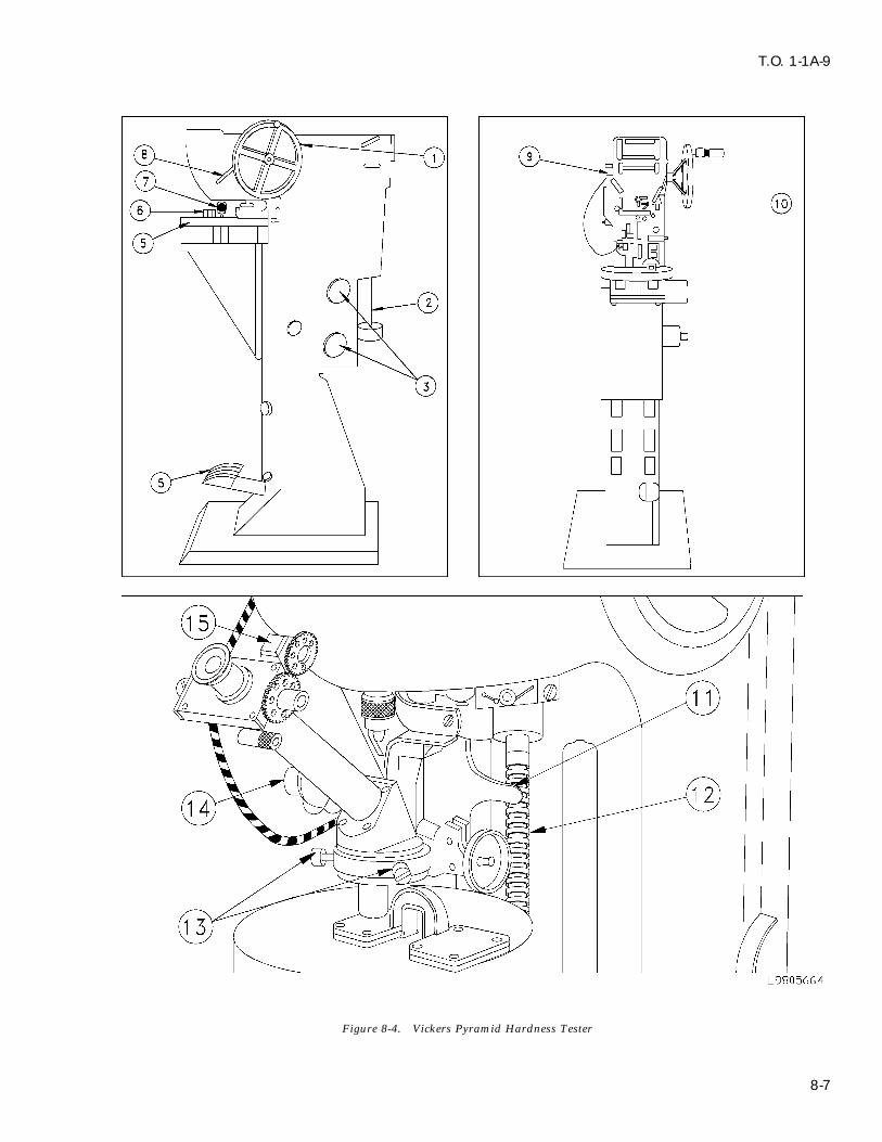
T.O. 1-1A-9
Figure 8-4. Vickers Pyramid Hardness Tester
8-7

T.O. 1-1A-9
8-18. SHORE SCLEROSCOPE HARDNESSTEST. The Shore scleroscope is not a precisioninstrument as the others discussed in precedingparagraphs. It is used to give approximate valuesfor comparative hardness readings. Testing hard-ness with the scleroscope consists of dropping adiamond tipped hammer upon the test specimenfrom a definite height and measuring the reboundproduced. In one type of tester, the height of therebound must be measured directly on the scale ofthe machine, while on another the amount is indi-cated on a dial.
8-19. The Scleroscope Tester. The tester (Figure8-6) consists of the following major parts:
a. A base, provided with leveling screws, enda clamping arrangement to hold the sample to betested.
Figure 8-5. Standard Pyramid Diamond Indentor
g. Bring the left corner of the impression, bymeans of the centering screws (13) to a pointwhere it touches the left hand fixed knife edge.Adjust the right hand movable knife edge bymeans of the micrometric screw connected to thecounter until it touches the right hand corner ofthe impression. The counter (15) will then showan ocular reading which is transposed to the Vick-ers pyramid numeral by use of correlation tablesaccompanying the tester.
h. Where specified hardness limits aredesired the third knife edge is used. This ismoved by means of special screws to correspond tothe smaller dimension or maximum hardness,while the micrometer-controlled knife edge isadjusted to correspond to the minimum hardnessor larger dimension. When the settings of the sec-ond and third knife edges are made, it is only nec-essary when taking readings to set the fixed knife
Figure 8-6. Shore Scleroscopeedge to the left hand corner of the impression inthe usual way. If the right hand corner of theimpression appears between the second and third b. A vertical glass tube, mounted to the baseknife edges, the material has the proper hardness and containing the cylindrical diamond pointfor the range desired. hammer.
8-8

T.O. 1-1A-9
c. A suction heat and bulb for lifting and b. When an extensometer is required to deter-releasing the hammer. mine elastic properties, dimensions C and L may
be modified. In all cases the percentage of elonga-d. A scale, visible through the glass tube, for tion shall be based on dimension G.determining the height of the rebound.c. The type R1 test specimen is circular ine. A magnifier hammer with a larger contact cross section and is used for bars, rods, forgings,area is supplied for use with extremely soft plates, shapes, heavy-walled tubing, and castings.metals. Types R2, R3, R4, and R5 are circular in cross-sec-
tion and are used for material of dimensions insuf-8-20. TESTING WITH THE SCLEROSCOPE.ficient for type R1.The test is made as follows:
(1) The ends of the reduced section shalla. Level the instrument by means of thenot differ in width by more than 0.004 inch.adjusting screws (1). (See figure 8-6). The level
position is determined by means of the plumb rod (2) The ends of the specimen shall be sym-(2). metrical with the center line of the reduced sectionwithin 0.10 inch.b. Prepare the test specimen as described for
the Brinell and Rockwell tests in preceding (3) When material is over 2 inches thick,paragraphs and clamp it on the base. This is done machine to 3/4 inch or use type R1 test specimen.by raising the lever (3) inserting the sample and For more detailed information, refer to Federalexerting the pressure on the clamping shoe (4). Test Method Standard No. 151.c. Raise the hammer (5) by squeezing and 8-22. DECARBURIZATION MEASUREMENT.releasing the bulb (6)
8-23. Decarburization is the loss of carbon at thed. Release the hammer by again squeezing surface of ferrous materials which have beenthe bulb and observing its rebound. heated for fabricating, welding, etc., or whenheated to modify mechanical properties. Effectivee. Several tests should be made at differentdecarburization is any measurable loss of carbonpoints of a specimen, and an average readingcontent which results in mechanical propertiestaken to reduce visual error.below the minimum acceptable specifications for
8-21. TENSILE TESTING. The terms tension hardened materials. The most common methodstest and compression test are usually taken to used to measure decarburization are microscopic,refer to tests in which a prepared specimen is sub- hardness and chemical. The microscopic method isjected to a gradually increasing load applied axi- sufficiently accurate for most annealed and hotally until failure occurs . For the purpose of ten- rolled material for small amounts of decarburiza-sile testing implied by this technical order this tion in high carbon (over 0.60%), high hardnesstype of setting would apply to determining the steels. The hardness method is insensitive in thismechanical properties desired in a material. For case, and recourse must be taken to chemical anal-this test, the following test specimens are listed. ysis. In this technical order, only the hardness(See Figure 8-7.) This does not exclude the use of method is covered. When precise measurementsother test specimens for special materials or forms are required, publications giving detailed measure-of material. The tensile strength shall be deter- ments must be consulted.mined by dividing the maximum load on the speci-men during a tension test by the original cross-sectional area of the specimen.
a. Diameter of the reduced section may besmaller at center than at ends. Difference shallnot exceed 1% of diameter at ends.
8-9
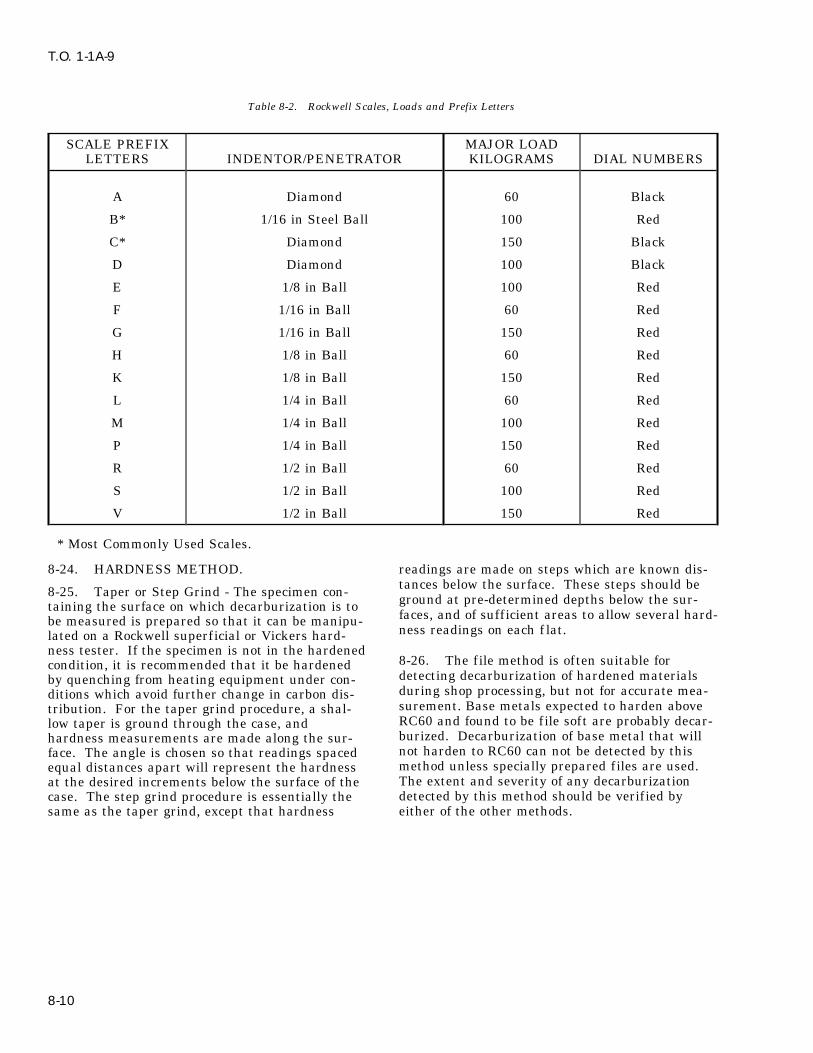
T.O. 1-1A-9
Table 8-2. Rockwell Scales, Loads and Prefix Letters
SCALE PREFIX MAJOR LOADLETTERS INDENTOR/PENETRATOR KILOGRAMS DIAL NUMBERS
A Diamond 60 Black
B* 1/16 in Steel Ball 100 Red
C* Diamond 150 Black
D Diamond 100 Black
E 1/8 in Ball 100 Red
F 1/16 in Ball 60 Red
G 1/16 in Ball 150 Red
H 1/8 in Ball 60 Red
K 1/8 in Ball 150 Red
L 1/4 in Ball 60 Red
M 1/4 in Ball 100 Red
P 1/4 in Ball 150 Red
R 1/2 in Ball 60 Red
S 1/2 in Ball 100 Red
V 1/2 in Ball 150 Red
* Most Commonly Used Scales.
8-24. HARDNESS METHOD. readings are made on steps which are known dis-tances below the surface. These steps should be8-25. Taper or Step Grind - The specimen con- ground at pre-determined depths below the sur-taining the surface on which decarburization is tofaces, and of sufficient areas to allow several hard-be measured is prepared so that it can be manipu-ness readings on each f lat.lated on a Rockwell superficial or Vickers hard-
ness tester. If the specimen is not in the hardened8-26. The file method is often suitable forcondition, it is recommended that it be hardeneddetecting decarburization of hardened materialsby quenching from heating equipment under con-during shop processing, but not for accurate mea-ditions which avoid further change in carbon dis-surement. Base metals expected to harden abovetribution. For the taper grind procedure, a shal-RC60 and found to be file soft are probably decar-low taper is ground through the case, andburized. Decarburization of base metal that willhardness measurements are made along the sur-not harden to RC60 can not be detected by thisface. The angle is chosen so that readings spacedmethod unless specially prepared files are used.equal distances apart will represent the hardnessThe extent and severity of any decarburizationat the desired increments below the surface of thedetected by this method should be verified bycase. The step grind procedure is essentially theeither of the other methods.same as the taper grind, except that hardness
8-10

T.O. 1-1A-9
Figure 8-7. Test Specimens
8-11

T.O. 1-1A-9
Table 8-3. Approximate Hardness - Tensile Strength Relationship of Carbon and Low Alloy Steels
Rockwell Vickers Brinell3 Tensile
Diamond 300 Kg Load - 10mm Ball Strength
C B Pyramid Tungsten 1000 lb150 Kg 100 Kg 50 Kg Carbide Steel perLoad Load Load Ball Ball sq in.
1/16 Ball
67 918 820 71766 884 796 70165 852 774 68664 822 753 67163 793 732 65662 765 711 64261 740 693 62860 717 675 61359 694 657 60058 672 639 58457 650 621 57456 121.3 630 604 56155 120.8 611 588 54854 120.2 592 571 53653 119.6 573 554 524 28352 119.1 556 538 512 27351 118.5 539 523 500 26450 117.9 523 508 488 25649 117.4 508 494 476 24648 116.8 493 479 464 23747 116.2 479 465 453 23146 115.6 465 452 442 22145 115.0 452 440 430 21544 114.4 440 427 419 20843 113.8 428 415 408 20142 113.3 417 405 398 19441 112.7 406 394 387 18840 112.1 396 385 377 18139 111.5 386 375 367 17638 110.9 376 365 357 17037 110.4 367 356 347 16536 109.7 357 346 337 16035 109.1 348 337 327 15534 108.5 339 329 318 15033 107.8 330 319 309 14732 107.1 321 310 301 14231 106.4 312 302 294 13930 105.7 304 293 286 13629 105.0 296 286 279 13228 104.3 288 278 272 12927 130.7 281 271 265 12626 102.9 274 264 259 12325 102.2 267 258 253 12024 101.5 261 252 247 11823 100.8 255 246 241 11522 100.2 250 241 235 11221 99.5 245 236 230 11020 98.9 240 231 225 107
8-12

T.O. 1-1A-9
Table 8-3. Approximate Hardness - Tensile Strength Relationship of Carbon and Low Alloy Steels - Continued
Rockwell Vickers Brinell3 Tensile
Diamond 300 Kg Load - 10mm Ball Strength
C B Pyramid Tungsten 1000 lb150 Kg 100 Kg 50 Kg Carbide Steel perLoad Load Load Ball Ball sq in.
1/16 Ball
19 98.1 235 226 220 10418 97.5 231 222 215 10317 96.9 227 218 210 10216 96.2 223 214 206 10015 95.5 219 210 201 9914 94.9 215 206 197 9713 94.1 211 202 193 9512 93.4 207 199 190 9311 92.6 203 195 186 9110 91.8 199 191 183 909 91.2 196 187 180 898 90.3 192 184 177 887 89.7 189 180 174 876 89 186 177 171 855 88.3 183 174 168 844 87.5 179 171 165 833 87 177 169 162 822 86 173 165 160 811 85.5 171 163 158 800 84.5 167 159 154 78
83.2 162 153 150 7682 157 148 145 74
80.5 153 144 140 7279 149 140 136 70
77.5 143 134 131 6876 139 130 127 6674 135 126 122 6472 129 120 117 6270 125 116 113 6068 120 111 108 5866 116 107 104 5664 112 104 100 5461 108 100 96 5258 104 95 92 5055 99 91 87 4851 95 86 83 4647 91 83 79 4444 88 80 76 4239 84 76 72 4035 80 72 68 3830 76 67 64 3624 72 64 60 3420 69 61 57 3211 65 57 53 300 62 54 50 28
8-13

T.O. 1-1A-9
8-27. NONDESTRUCTIVE INSPECTION south poles which will attract magnetic particlesMETHODS. applied to the material. Discontinuities are visible
due to color contrast between the magnetic parti-8-28. Radiographic inspection will show internal cles and the background surface. All magneticand external structural details of all types of parts particle inspections shall be accomplished in accor-and materials. It is accomplished by passing pene- dance with T.O. 33B-1-1 and MIL-STD-410.trating radiation (usually X or gamma rays)through the part or assembly being inspected to 8-32. Eddy current inspection is used to detectexpose a film. After developing, interpretation of discontinuities in materials that are conductors ofthe radiograph will indicate defects or damage. electricity. An eddy current is the circulating elec-All radiographic inspections shall be accomplished trical current induced in a conductor by an alter-in accordance with T.O. 33B-1-1, MIL-STD-453, nating magnetic f ield, which is produced by aand MIL-STD-410. small test coil in contact with or close to the mate-
rial being inspected. Discontinuities in the mate-8-29. Penetrant inspection is a nondestructive rial being tested cause variations in the inducedinspection method that is used to detect disconti- eddy current. The test coil measures the varia-nuities open to the surface of nonporous material. tions which reveal discontinuities in the material.It is accomplished by treating the inspection area All eddy current inspections shall be in accordancewith a f luid (penetrant) that penetrates the sur- with T.O. 33B-1-1 and MIL-STD-410.face discontinuity. Surplus penetrant remainingon the surface is removed and an absorbent mate- 8-33. CHEMICAL ANALYSIS. Chemical analy-rial (developer) is applied to the surface. The sis methods are those in which the elements pre-developer acts as a blotter and draws some of the sent in metals are determined by the use ofpenetrant from the discontinuity to the surface. reagents in solution, by combustion methods, or byDiscontinuities are visible due to color contrast other none-mission methods. Sample metal frombetween the penetrant drawn out and the back- any piece shall be such that it represents as nearlyground surface. Only f luorescent penetrants are as possible the metal of the entire piece. Drilling,approved for Air Force use. All penetrant inspec- milling and other machining operations for sampletion materials shall conform to MIL-I-25135. All metal shall be performed without the use of water,penetrant inspections shall be accomplished in oil, or other lubricants, and cutting speeds shall beaccordance with T.O. 33B-1-1 and MIL-STD-410. such that no burning takes place to cause alterna-
tion of the chemical composition of the test metal.8-30. Ultrasonic inspection uses a high frequency Method III.I of Federal Method Standard 151A issound wave to detect discontinuities in materials. the controlling document for chemical analysis.The pulser in the ultrasonic instrument sends anelectrical impulse to a piezoelectric material in the 8-34. SPECTROCHEMICAL ANALYSIS. Spec-search unit (transducer). The transducer changes trochemical analysis includes all methods in whichthe electrical impulse into mechanical vibrations measurements of electromagnetic radiations pro-(sound) and transmits them into the material duced by a sample metal are employed to deter-being inspected. Any marked change in acoustic mine the chemical composition. Samples shall beproperties, such as a f law or interface in the mate- so selected as to be representative of the entirerial, ref lects the sound back to the transducer. quantity of metal under inspection. CuttingExamination of the ref lections on a cathode ray speeds in all machining operations shall be suchtube will reveal discontinuities in the material. that no burning takes place to cause alteration ofAll ultrasonic inspections shall be accomplished in the chemical composition of the test metal.accordance with T.O. 33B-1-1, MIL-I-8950, and Method 112.1 of Federal Test Method StandardMIL-STD-410. 151A governs this type of analysis. The result of
spectrochemical analysis shall be determined to8-31. Magnetic particle inspection is used to the number of decimal places shown in the chemi-detect discontinuities in ferromagnetic materials, cal requirements for the material.principally iron and steel. Magnetic particleinspection is accomplished by inducing a magneticfield into the material being inspected. A disconti-nuity will interrupt this f ield, creating north and
8-14

T.O. 1-1A-9
SECTION IX
HEAT TREATMENT
9-1. GENERAL. 9-8. Some typical material applications are listedin Table 9-1 for general guidance only. Cycle for
9-2. Controlled atmosphere ovens are not which an alloy type is listed may not necessarilyrequired for heat treatment operations unless be specified for that material.specified for a particular part.
9-9. SPECIAL HEAT TREATMENT9-3. A cold oven is defined as any oven where INFORMATION.the temperature is not over 500oF (260oC). Load-
9-10. CADMIUM PLATED PARTS. All cad-ing and unloading a cold oven is possible withoutmium plate shall be stripped from parts (SPOP 21)further lowering the temperature.and cadmium plated detail parts shall be removedfrom assemblies prior to subjecting the part or9-4. Parts that are prone to distortion duringassemblies to any furnace temperature in excess ofheat treatment shall be properly supported and500oF (260oC). At temperatures above 500oFtemperature raised gradually by steps. Coat f ix-(260oC), stress alloying of molten cadmium willturing at part contact points and threaded detailsoccur with potentially harmful results on the basewith PMC 2264 boron nitride coating prior tomaterials.installing part and before heat treatment. Cooling
of these parts shall also be done gradually. Cycles 9-11. TINT TEST FOR DETERMINING COAT-with A suffix are recommended for this purpose. ING REMOVAL FROM NICKEL BASE AND
COBALT BASE ALLOYS.9-5. Parts that are not prone to distortion duringheat treatment may be loaded into and withdrawn 9-12. Perform test as follows:from a hot oven.
a. Remove coating from parts using applicablestripping procedure.9-6. Temperature and time are the most critical
factors in heat treatment. Time required at each b. Heat parts and an uncoated, vapor blastedspecified temperature begins only after all sec- test panel of the same material as the parts attions of parts have reached that temperature. 1075o ±25oF (579o ±14oC) for 45 to 75 minutes inFurnace operator shall make allowance for size of air.part, number of parts, and furnace inputcapacities. c. A uniform color match between the part
and the test piece will indicate complete removal9-7. Optimum temperatures are given for each of the coating.cycle, with tolerances included for practical use.However, it is best to hold to basic temperatureslisted.
Table 9-1. Typical Heat Treatment Application
Cycle No. Type* SPOP No. Possible Alloy Application
1, 1A STR 455-1, 455-2 Low alloy steel, as AMS 6322 and AMS 6415; martensiticstainless steel, as Type 410 (AMS 5504 and AMS 5613) andGreek Ascoloy (AMS 5508 and AMS 5616)
2 STR 456 Aluminum
3 STR 457 -
4, 4A STR 458-1, 458-2 Inconel X
5, 5A STR 459-1, 459-2 Nickel alloys: B-1900 (PWA 663 and PWA 1455); Inconel713 (PWA 655) Cobalt alloys: Stellite 31 (AMS 5382); WI-52(PWA 653); MAR-M509 (PWA 647)
6, 6A STR 460-1, 460-2 Greek Ascoloy (AMS 5508 and AMS 5616) (martensiticstainless steel)
9-1

T.O. 1-1A-9
Table 9-1. Typical Heat Treatment Application - Continued
Cycle No. Type* SPOP No. Possible Alloy Application
7 STR 461 Waspaloy, Udimet 700
8 STR 455-3 -
9 STR 459-3 Inconel 600 (nickel alloy); Nimonic 75 (PWA 673) (nickelalloy); stainless steel, as Types 310, 316, 321, and 347
11 STR 464 Titanium
12, 12A PRE 471, 465 Inconel 718 (nickel alloy), as AMS 5596, AMS 5662, andAMS 5663
13 STR 466 17-7PH (stainless steel - austenite conditioning); Type 430(ferritic stainless steel), welded with Type 430 filler metal
14 STR 467 Type 430 (ferritic stainless steel), welded with AMS 5680(Type 347 stainless steel)
15 PRE 468 A-286 (modified Tinidur) stainless steel, as AMS 5525, AMS5731, AMS 5732, and AMS 5737
17 PRE 470 Incoloy 901 (nickel alloy), as AMS 5660 and AMS 5661
20 SOL 480 HASTELLOY X (nickel alloy)
21 SOL 481 Nickel alloy: HASTELLOY X (AMS 5536 and AMS 5754)Cobalt alloys: STELLITE 31 (AMS5382); Haynes 188 (AMS5608, AMS 5772, and PWA 1042); L-605 (AMS 5537 andAMS 5759)
22 STR 482 Nickel alloys: Inconel 600 (AMS 5540 and AMS 5665); In-conel 625 (AMS 5599 and AMS 5666); HASTELLOY N;HASTELLOY X (AMS 5536, AMS 5754, and PWA 1038);HASTELLOY W Cobalt alloys: STELLITE 31 (AMS 5382);Haynes 188 (AMS 5608, AMS 5772, and PWA 1042); L-605(AMS 5537 and AMS 5759); MAR-M509 (PWA 647)
101 SOL 761 Waspaloy (nickel alloy), as AMS 5544, AMS 5706, and AMS5707
102 SOL 762 Waspaloy (nickel alloy), as AMS 5544, AMS 5706, and AMS5707
103 STA 763 Waspaloy (nickel alloy), as AMS 5544, AMS 5706, AMS5707, AMS 5708, and AMS 5709
104 PRE 764 Waspaloy (nickel alloy), as AMS 5596, AMS 5706, AMS5707, AMS 5708, and AMS 5709
105 SOL 765 Inconel 718 (nickel alloy), as AMS 5596, AMS 5662, andAMS 5663
106 SOL 766 Inconel 718 (nickel alloy, as AMS 5596, AMS 5662, andAMS 5663
9-2
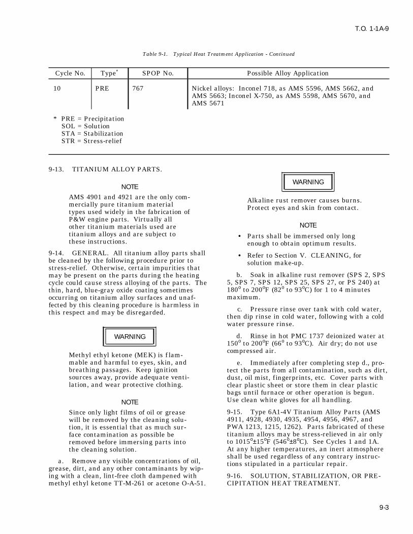
T.O. 1-1A-9
Table 9-1. Typical Heat Treatment Application - Continued
Cycle No. Type* SPOP No. Possible Alloy Application
10 PRE 767 Nickel alloys: Inconel 718, as AMS 5596, AMS 5662, andAMS 5663; Inconel X-750, as AMS 5598, AMS 5670, andAMS 5671
* PRE = PrecipitationSOL = SolutionSTA = StabilizationSTR = Stress-relief
9-13. TITANIUM ALLOY PARTS.
WARNINGNOTE
AMS 4901 and 4921 are the only com- Alkaline rust remover causes burns.mercially pure titanium material Protect eyes and skin from contact.types used widely in the fabrication ofP&W engine parts. Virtually all
NOTEother titanium materials used aretitanium alloys and are subject to . Parts shall be immersed only longthese instructions. enough to obtain optimum results.
9-14. GENERAL. All titanium alloy parts shall . Refer to Section V. CLEANING, forbe cleaned by the following procedure prior to solution make-up.stress-relief. Otherwise, certain impurities that
b. Soak in alkaline rust remover (SPS 2, SPSmay be present on the parts during the heating5, SPS 7, SPS 12, SPS 25, SPS 27, or PS 240) atcycle could cause stress alloying of the parts. The180o to 200oF (82o to 93oC) for 1 to 4 minutesthin, hard, blue-gray oxide coating sometimesmaximum.occurring on titanium alloy surfaces and unaf-
fected by this cleaning procedure is harmless inc. Pressure rinse over tank with cold water,this respect and may be disregarded.
then dip rinse in cold water, following with a coldwater pressure rinse.
d. Rinse in hot PMC 1737 deionized water atWARNING150o to 200oF (66o to 93oC). Air dry; do not usecompressed air.
Methyl ethyl ketone (MEK) is f lam-mable and harmful to eyes, skin, and e. Immediately after completing step d., pro-breathing passages. Keep ignition tect the parts from all contamination, such as dirt,sources away, provide adequate venti- dust, oil mist, f ingerprints, etc. Cover parts withlation, and wear protective clothing. clear plastic sheet or store them in clear plastic
bags until furnace or other operation is begun.Use clean white gloves for all handling.NOTE9-15. Type 6A1-4V Titanium Alloy Parts (AMSSince only light f ilms of oil or grease4911, 4928, 4930, 4935, 4954, 4956, 4967, andwill be removed by the cleaning solu-PWA 1213, 1215, 1262). Parts fabricated of thesetion, it is essential that as much sur-titanium alloys may be stress-relieved in air onlyface contamination as possible beto 1015o±15oF (546o±8oC). See Cycles 1 and 1A.removed before immersing parts intoAt any higher temperatures, an inert atmospherethe cleaning solution.shall be used regardless of any contrary instruc-
a. Remove any visible concentrations of oil, tions stipulated in a particular repair.grease, dirt, and any other contaminants by wip-ing with a clean, lint-free cloth dampened with 9-16. SOLUTION, STABILIZATION, OR PRE-methyl ethyl ketone TT-M-261 or acetone O-A-51. CIPITATION HEAT TREATMENT.
9-3

T.O. 1-1A-9
9-17. GENERAL. Solution heat treatment of 9-21. The expressions AIR COOL and AIR COOLmaterial (particularly HASTELLOY X) is per- OR FASTER mean that parts shall be cooledformed to improve ductility and weldability prior quickly enough to prevent metal structure changesto resizing and repair. Long-time exposure to high that can happen in certain alloys if cooling is tootemperature engine operating environment causes slow. It does not mean to quench in a liquid. Cir-precipitation of carbides into the grain boundaries. culating fans may be used, but f ixturing may beCarbides, particularly chromium carbides, are thus required if distortion is a problem.precipitated into the grain boundaries of parts fab-
a. AIR COOL is defined as rate of cooling ofricated of HASTELLOY X material and subjectedpart obtained by removing that part from furnacefor long periods to temperatures of 1200o to 1700oFat prescribed temperature and allowing it to cool(649o to 927oC). The solution treatment dissolvesin room temperature still air. Definition has beenthese carbides and puts them back into metallicbroadened to include the following situations.solution. The cooling cycle, therefore, shall be
rapid enough to maintain carbides or precipitation (1) In vacuum furnace, by force cooling inhardeners in solution. Replication and metallurgi- protective atmosphere.cal examination may be necessary to verifywhether fixturing and cooling rate are adequate to (2) In protective atmosphere furnace, byobtain desired microstructure and prevent shutting off heat and maintaining atmosphericcracking. f low rates.
9-18. Stabilization heat treatment is maintaining (3) In retort furnace, by removing retorta part at a selected temperature long enough to from furnace and fan cooling.rearrange the atoms into an improved structure.
(4) In pit furnace, by removing parts from9-19. Precipitation heat treatment is a selected furnace and cooling in room temperature still air.temperature and duration that produces beneficial
b. AIR COOL OR FASTER is defined as cool-hardening in certain alloys. It is sometimesing not less than 40oF (22oC) per minute to 1100oFreferred to as Aging, or Age Hardening.(593oC) and not less than 15oF (8oC) from 1100o to
9-20. When a sequence of solution, stabilization, 1000oF (538oC).or precipitation heat treatment is applied to agiven part, various temperatures are used. The 9-22. Cycle number, type of heat treatment,final condition obtained is a combined effect of SPOP number, and maximum temperature arethis sequence. listed in Table 9-2.
Table 9-2. Cross-Index for Solution, Stabilization, or Precipitation Heat Treatments
Cycle No. Type SPOP No. Peak Temp., oF(oC)*
12 Precipitation 471 1350 (732)12A Precipitation 465 1350 (732)15 Precipitation 468 1325 (718)17 Precipitation 470 1450 (788)20 Solution 480 2050 (1121)21 Solution 481 2150 (1177)101 Solution 761 1825 (996)102 Solution 762 1825 (996)103 Stabilization 763 1550 (843)104 Precipitation 764 1400 (760)105 Solution 765 1750 (954)106 Solution 766 1750 (954)107 Precipitation 767 1325 (718)
* (disregarding tolerance)
9-23. Solution heat treatment Cycles 20 and 21 instructions, as necessary, by cycle or SPOPare used for various HASTELLOY X parts. Refer- number.ence to these cycles will be made in the repair
9-4

T.O. 1-1A-9
NOTE manufacture. The beneficial proper-ties derived from this lower tempera-These cycles apply only to the repairture treatment could be lost perma-of HASTELLOY X parts that requirenently if subjected to a temperatureusing one of the following solutionhigher than 1800oF (982oC). For reg-heat treatments. The specific cycleular Hastelloy material, solution heatrequired will be included in the repairtreat shall be performed in accordanceprocedure.with Cycle 20 (SPOP 480), unless oth-erwise directed by a specific repair9-24. CYCLE 20 (SPOP 480). Perform asprocedure.follows:
a. Heat part to 2150o ±25oF (1177o ±14oC) andhold for 7 to 10 minutes.
CAUTIONNOTE
Do not use this cycle for solution heatHydrogen, argon, or air are acceptabletreating PWA 1038 HASTELLOY Xatmospheres. However, when solu-material. This material was solutiontion treating is to be followed by weldtreated at 1950oF (1066oC) at itsrepair that requires complete priormanufacture. The beneficial proper-removal of oxides, hydrogen is pre-ties derived from this lower tempera-ferred because of its characteristicture treatment could be lost perma-and beneficial cleaning action overnently if subjected to a temperaturethe entire part. Hydrogen cleaninghigher than 1800oF (982oC). Forremoves oxides from all surfacesother HASTELLOY alloys, solutionincluding those diff icult to cleanheat treat shall be performed per thismechanically, and to some extent,cycle unless otherwise directed by afrom the inside of cracks to be welded.specific repair procedure.
b. Air cool or faster.a. Heat part to 2050o ±25oF (1121o ±14oC) and
9-26. The following solution, stabilization, or pre-hold for 7 to 10 minutes.cipitation heat treatment cycles apply primarily tocertain age-hardenable alloys such as WASPALOYand INCONEL materials, for stress-relief, and toNOTEdissolve precipitated carbides and intermetallics
Hydrogen, argon, or air are acceptable (hardeners).atmospheres; however, when solutiontreating is to be followed by weld
NOTErepair that requires complete priorThese cycles apply only when specifi-removal of oxides, hydrogen is pre-cally invoked in repair procedures inferred because of its characteristicengine publications. Parts that areand beneficial cleaning action oversusceptible to distortion during heatthe entire part. Hydrogen cleaningtreatment shall be adequately sup-removes oxides from all surfaces,ported, and temperature raised andincluding those diff icult to cleanlowered stepwise. The Suffix A fol-mechanically, and to some extent,lowing a cycle number indicates afrom the inside of cracks to be welded.stepwise cycle. Step cycles shall not
b. Air cool or faster. be used for solution heat treatments.Refer to cautions in solution heat
9-25. CYCLE 21 (SPOP 481). Perform as treat cycles.follows:
9-27. CYCLE 12 (SPOP 471). Perform asfollows:
CAUTIONNOTE
Do not use this cycle for solution heat This is a short-term precipitationtreating PWA 1038 HASTELLOY X (aging) heat treatment for INCONELmaterial. This material was solution 718 or other part material specifiedtreated at 1950oF (1066oC) at its in engine publication.
9-5
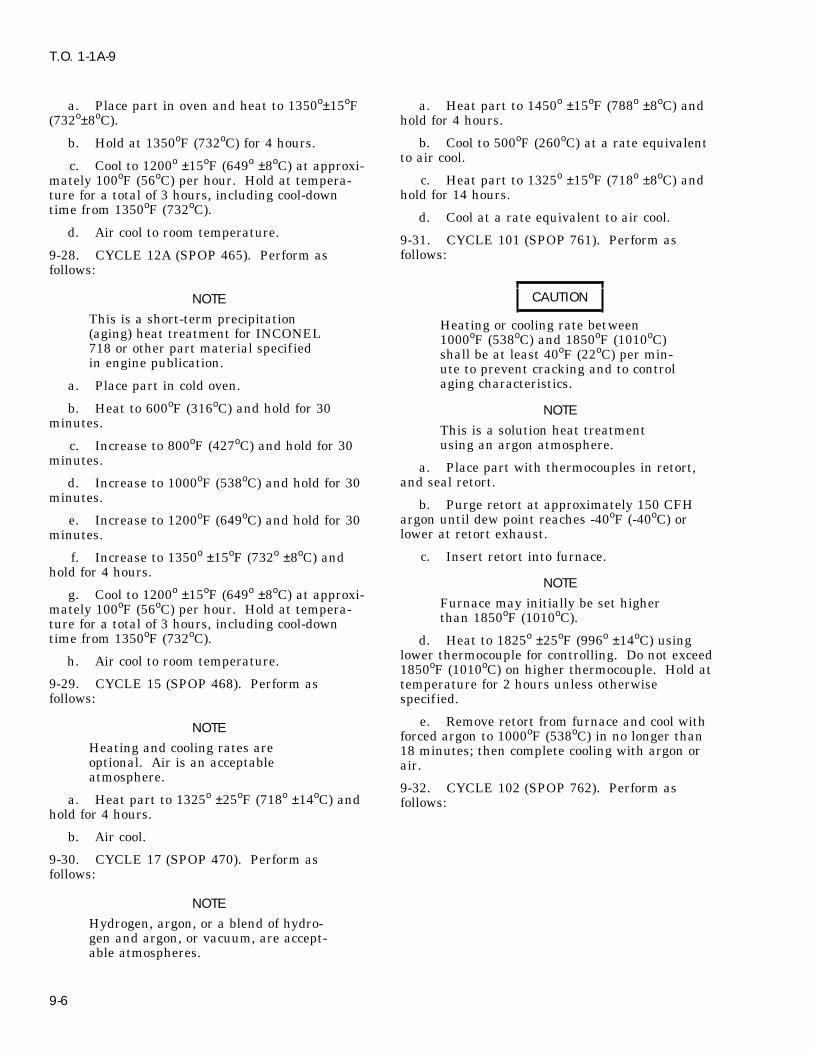
T.O. 1-1A-9
a. Place part in oven and heat to 1350o±15oF a. Heat part to 1450o ±15oF (788o ±8oC) and(732o±8oC). hold for 4 hours.
b. Cool to 500oF (260oC) at a rate equivalentb. Hold at 1350oF (732oC) for 4 hours.to air cool.
c. Cool to 1200o ±15oF (649o ±8oC) at approxi-c. Heat part to 1325o ±15oF (718o ±8oC) andmately 100oF (56oC) per hour. Hold at tempera-
hold for 14 hours.ture for a total of 3 hours, including cool-downtime from 1350oF (732oC). d. Cool at a rate equivalent to air cool.
d. Air cool to room temperature. 9-31. CYCLE 101 (SPOP 761). Perform asfollows:9-28. CYCLE 12A (SPOP 465). Perform as
follows:
CAUTIONNOTE
This is a short-term precipitation Heating or cooling rate between(aging) heat treatment for INCONEL 1000oF (538oC) and 1850oF (1010oC)718 or other part material specified shall be at least 40oF (22oC) per min-in engine publication. ute to prevent cracking and to control
aging characteristics.a. Place part in cold oven.
b. Heat to 600oF (316oC) and hold for 30 NOTEminutes. This is a solution heat treatment
using an argon atmosphere.c. Increase to 800oF (427oC) and hold for 30minutes. a. Place part with thermocouples in retort,
and seal retort.d. Increase to 1000oF (538oC) and hold for 30minutes. b. Purge retort at approximately 150 CFH
argon until dew point reaches -40oF (-40oC) ore. Increase to 1200oF (649oC) and hold for 30lower at retort exhaust.minutes.
c. Insert retort into furnace.f. Increase to 1350o ±15oF (732o ±8oC) andhold for 4 hours.
NOTEg. Cool to 1200o ±15oF (649o ±8oC) at approxi-
Furnace may initially be set highermately 100oF (56oC) per hour. Hold at tempera-than 1850oF (1010oC).ture for a total of 3 hours, including cool-down
time from 1350oF (732oC). d. Heat to 1825o ±25oF (996o ±14oC) usinglower thermocouple for controlling. Do not exceedh. Air cool to room temperature.1850oF (1010oC) on higher thermocouple. Hold at
9-29. CYCLE 15 (SPOP 468). Perform as temperature for 2 hours unless otherwisefollows: specified.
e. Remove retort from furnace and cool withNOTEforced argon to 1000oF (538oC) in no longer than
Heating and cooling rates are 18 minutes; then complete cooling with argon oroptional. Air is an acceptable air.atmosphere.
9-32. CYCLE 102 (SPOP 762). Perform asa. Heat part to 1325o ±25oF (718o ±14oC) and follows:
hold for 4 hours.
b. Air cool.
9-30. CYCLE 17 (SPOP 470). Perform asfollows:
NOTE
Hydrogen, argon, or a blend of hydro-gen and argon, or vacuum, are accept-able atmospheres.
9-6

T.O. 1-1A-9
NOTE
This is a precipitation heat treatmentCAUTIONusing air, argon, or vacuum.
Heating or cooling rate betweena. Place part in cold furnace.1000oF (538oC) and 1850oF (1010oC)
shall be at least 40oF (22oC) per min-b. Heat to 1400o ±15oF (760o ±8.3oC) for 16ute to prevent cracking and to control
hours.aging characteristics.
c. Air cool.NOTE
9-35. CYCLE 105 (SPOP 765). Perform as. This is a solution heat treatment follows:using vacuum. Heat cycle shall becompleted in the 0.010 torr range orlower. CAUTION. Furnace system shall provide for
Heating or cooling rate betweenargon forced cooling, in order to sat-1000oF (538oC) and 1775oF (968oC)isfy cooling rate requirement.shall be at least 40oF (22oC) per min-ute to prevent cracking and to controla. Place part, with thermocouples, in furnace.aging characteristics.
b. Evacuate to 0.009 torr or lower. Staticleak rate shall not exceed 50 microns per hour.
NOTE
This is a solution heat treatmentNOTE using an argon atmosphere.Furnace may initially be set higher
a. Place part with thermocouples in retort,than 1850oF (1010oC).and seal retort.
c. Heat to 1825o ±25oF (996o ±14oC) usinglower thermocouple for controlling. Do not exceed b. Purge retort at approximately 150 CFH1850oF (1010oC) on higher thermocouple. Hold at argon until dew point reaches -40oF (-40oC) ortemperature for 2 hours unless otherwise lower, at retort exhaust.specified.
c. Insert retort into furnace.d. Cool at required rate using forced argon.
NOTE9-33. CYCLE 103 (SPOP 763). Perform asfollows: Furnace may initially be set higher
than 1775oF (968oC).NOTE
d. Heat to 1750o ±25oF (954o ± 14oC), usingThis is a stabilization heat treatment lower thermocouple for controlling. Do not exceedusing air, argon, or vacuum. 1775oF (968oC) on higher thermocouple. Hold at
temperature for 1 hour unless otherwise specified.a. Place part in cold furnace.e. Remove retort from furnace and cool withb. Heat to 1550o ±15oF (843o ±8.3oC) for 4
forced argon to 1000oF (538oC) in no longer thanhours.16 minutes; then complete cooling with argon orair.c. Air cool.
9-34. CYCLE 104 (SPOP 764). Perform as 9-36. CYCLE 106 (SPOP 766). Perform asfollows: follows:
9-7

T.O. 1-1A-9
NOTELocal stress-relief of engine parts fol-CAUTIONlowing minor repairs is authorizedonly if procedure has been developedHeating or cooling rate betweento be compatible with applicable1000oF (538oC) and 1775oF (968oC)parts, material, size, and operatingshall be at least 40oF (22oC) per min- environment, and is approved by theute to prevent cracking and to control cognizant engineering authority.aging characteristics.
9-39. GENERAL. Parts that have been repairedNOTE by fusion welding shall ordinarily be stress-
relieved.. This is a solution heat treatmentusing vacuum. Heat cycle shall becompleted in the 0.010 torr range or CAUTIONlower.
The required stress-relief (Cycle 1 or. Furnace system shall provide for1A) after welding or brazing Type 410argon forced cooling, in order to sat-or Greek Ascoloy materials eliminatesisfy cooling rate requirement. the brittleness in the joint areas. Toavoid cracking, parts shall be handleda. Place part, with thermocouples, in furnace.carefully until stress-relief is
b. Evacuate to 0.009 torr or lower. Static accomplished.leak rate shall not exceed 0.05 torr per hour.
NOTENOTEOn certain parts, experience has indi-Furnace may initially be set highercated that stress-relief is notthan 1775oF (968oC).required. This permissible omission
c. Heat to 1750o ±25oF (954o ±14oC), using will be included in appropriate man-lower thermocouple for controlling. Do not exceed ual repair section for such parts.1775oF (968oC) on higher thermocouple. Hold at
9-40. The following stress-relief cycles are usedtemperature for 1 hour unless otherwise specified.throughout manual for various parts. Reference to
d. Cool at required rate using forced argon. these cycles will be made, as necessary, by cycle orSPOP number.9-37. CYCLE 107 (SPOP 767). Perform as
follows:NOTENOTE . Parts may require a cycle differentThis is a precipitation heat treatment from one of the following. This willusing air or argon. result in cycle being included in spe-
cific repair procedure.a. Place part in cold furnace.
b. Heat to 1325o ±15oF (718o ±8.3oC) for 8 . Parts that are susceptible to distor-hours. tion during heat treatment shall be
adequately supported, and tempera-c. Furnace cool at a rate not to exceed 100oF ture raised and lowered stepwise.(56oC) per hour to 1150o ±15oF (621o ±8.3oC); hold The Suffix A following a cycle numberfor 8 hours. indicates a stepwise cycle.d. Air cool. 9-41. Cycle number, SPOP number, and maxi-
mum temperature are listed in Table 16-3.9-38. STRESS-RELIEF AFTER WELDING.
9-8

T.O. 1-1A-9
Table 9-3. Cross-Index for Stress-Relief Heat Treatments
Cycle No. SPOP No. Peak Temp., oF(oC)*
1 455-1 1015 (546)1A 455-2 1015 (546)2 456 350 (177)3 457 900 (482)4 458-1 1300 (704)4A 458-2 1300 (704)5 459-1 1600 (871)5A 459-2 1600 (871)6 460-1 1050 (566)6A 460-2 1050 (566)7 461 1500 (816)8 455-3 1010 (543)9 459-3 1600 (871)11 464 1150 (621)13 466 1400 (760)14 467 1500 (816)22 482 1800 (982)
* (disregarding tolerance)
9-42. CYCLE 1 (SPOP 455-1). Heat part to d. Cool to 500oF (260oC) not faster than 100oF1015oF ±15oF (546o ±8oC) and hold for 2 hours. (56oC) every 15 minutes.
9-46. CYCLE 4 (SPOP 458-1). Heat part toNOTE 1300o ±25oF (704o ±14oC) and hold for 2 hours.
To minimize distortion, use Cycle 1Aas an alternate. Other cycles are per-
NOTEmissible provided stress-relief require-To minimize distortion, temperaturement of 1015o ±15oF (546o ±8oC) for 2may be raised and cooled gradually inhours is met.accordance with Cycle 4A. Other
9-43. CYCLE 1A (SPOP 455-2). Perform as cycles are permissible provided stress-follows: relief requirement of 1300o ±25oF
(704o ±14oC) for 2 hours is met.a. Put part in cold oven.
b. Heat to 600oF (316oC) and hold for 30 9-47. CYCLE 4A (SPOP 458-2). Perform asminutes. follows:
c. Increase to 800oF (427oC) and hold for 30 a. Put part in cold oven.minutes.
b. Heat to 600oF (316oC) and hold for 30d. Increase to 1015o ±15oF (546o ±8oC) and minutes.hold for 2 hours.c. Increase to 800oF (427oC) and hold for 30e. Cool to 500oF (260oC) not faster than 100oF
minutes.(56oC) every 15 minutes.
d. Increase to 1100oF (593oC) and hold for 309-44. CYCLE 2 (SPOP 456). Heat part to 350o
minutes.±10oF (177o ±6oC) and hold for 1 hour.
9-45. CYCLE 3 (SPOP 457). Perform as follows: e. Increase to 1300oF ±25oF (704o ±15oC) andhold for 2 hours.a. Put part in cold oven.
f. Cool to 500oF (260oC) not faster than 100oFb. Heat to 600oF (316oC) and hold for 30(56oC) every 15 minutes.minutes.
c. Increase to 900o ±15o(482o ±8oC) and hold 9-48. CYCLE 5 (SPOP 459-1). Heat part tofor 4 hours. 1600o±25oF (871o ±14oC) and hold for 2 hours.
9-9
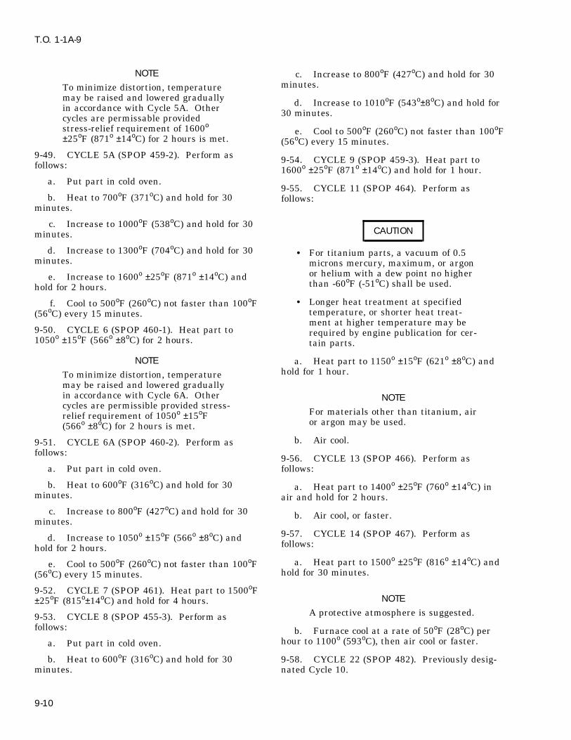
T.O. 1-1A-9
NOTE c. Increase to 800oF (427oC) and hold for 30minutes.To minimize distortion, temperature
may be raised and lowered gradually d. Increase to 1010oF (543o±8oC) and hold forin accordance with Cycle 5A. Other 30 minutes.cycles are permissable providedstress-relief requirement of 1600o
e. Cool to 500oF (260oC) not faster than 100oF±25oF (871o ±14oC) for 2 hours is met. (56oC) every 15 minutes.
9-49. CYCLE 5A (SPOP 459-2). Perform as 9-54. CYCLE 9 (SPOP 459-3). Heat part tofollows: 1600o ±25oF (871o ±14oC) and hold for 1 hour.a. Put part in cold oven.
9-55. CYCLE 11 (SPOP 464). Perform asb. Heat to 700oF (371oC) and hold for 30 follows:
minutes.
c. Increase to 1000oF (538oC) and hold for 30CAUTIONminutes.
d. Increase to 1300oF (704oC) and hold for 30 . For titanium parts, a vacuum of 0.5minutes. microns mercury, maximum, or argon
or helium with a dew point no highere. Increase to 1600o ±25oF (871o ±14oC) andthan -60oF (-51oC) shall be used.hold for 2 hours. . Longer heat treatment at specifiedf. Cool to 500oF (260oC) not faster than 100oFtemperature, or shorter heat treat-(56oC) every 15 minutes.ment at higher temperature may be
9-50. CYCLE 6 (SPOP 460-1). Heat part to required by engine publication for cer-1050o ±15oF (566o ±8oC) for 2 hours. tain parts.
NOTE a. Heat part to 1150o ±15oF (621o ±8oC) andhold for 1 hour.To minimize distortion, temperature
may be raised and lowered graduallyin accordance with Cycle 6A. Other NOTEcycles are permissible provided stress-
For materials other than titanium, airrelief requirement of 1050o ±15oFor argon may be used.(566o ±8oC) for 2 hours is met.
b. Air cool.9-51. CYCLE 6A (SPOP 460-2). Perform asfollows:
9-56. CYCLE 13 (SPOP 466). Perform asa. Put part in cold oven. follows:
b. Heat to 600oF (316oC) and hold for 30 a. Heat part to 1400o ±25oF (760o ±14oC) inminutes. air and hold for 2 hours.
c. Increase to 800oF (427oC) and hold for 30 b. Air cool, or faster.minutes.
9-57. CYCLE 14 (SPOP 467). Perform asd. Increase to 1050o ±15oF (566o ±8oC) andfollows:hold for 2 hours.
a. Heat part to 1500o ±25oF (816o ±14oC) ande. Cool to 500oF (260oC) not faster than 100oFhold for 30 minutes.(56oC) every 15 minutes.
9-52. CYCLE 7 (SPOP 461). Heat part to 1500oFNOTE±25oF (815o±14oC) and hold for 4 hours.
A protective atmosphere is suggested.9-53. CYCLE 8 (SPOP 455-3). Perform asfollows: b. Furnace cool at a rate of 50oF (28oC) per
hour to 1100o (593oC), then air cool or faster.a. Put part in cold oven.
b. Heat to 600oF (316oC) and hold for 30 9-58. CYCLE 22 (SPOP 482). Previously desig-minutes. nated Cycle 10.
9-10

T.O. 1-1A-9
9-65. Choice of method depends upon size andshape of joint, part configuration, and accessibil-CAUTIONity. Resistance blankets and quartz lamps can beused to 1350oF (732oC); induction heaters andParts shall be thoroughly cleanedradiant gas burners can be used to 1825oF (996oC).before entering oven.
NOTECAUTION
Hydrogen, argon, vacuum, or air areacceptable atmospheres; however, Thermocouples shall not be tackwhen heat treatment is to be followed welded to titanium parts.by weld repair, hydrogen is preferablebecause of its cleaning action on 9-66. Temperature profile shall be monitoredoxides and impurities diff icult to with tack welded thermocouples to provide accu-clean mechanically, as within cracks rate readout for manual or automatic control dur-or cavities. ing heat treat cycle. Thermocouples shall be
located every 2 inches of area that is to be stress-a. Place part in cold oven; however, this steprelieved. Following the cycle, thermocouples aremay be omitted for thin sheet metal parts.broken or ground off, and part blended to original
b. Heat part to 1800o ±25oF (982o ±14oC) and contour.hold for 1 hour.
9-67. Stress-relief duration and temperaturec. Air cool.shall be the same as for a corresponding furnace
9-59. LOCAL STRESS-RELIEF. heat treat, unless otherwise specified in applicableengine technical orders.
9-60. GENERAL. Local stress-relief is the appli-cation of a heat treatment cycle, using a portable 9-68. DESCRIPTION OF METHODS. Localheating system, to a part that has been weld
stress-relief methods are defined in the followingrepaired, usually without disassembly. Elaborateparagraphs.fixturing is avoided when stress-relieving minor
areas of large components.9-69. Resistance. Heaters consist of nichrome
9-61. Approval for local stress-relief is governed wire elements insulated with ceramic fiber andin part by accessibility, temperature requirement, contained within a f lexible wire jacket. Theseand configuration and material of part. components are woven into a thermal blanket,
which shall be held in close contact with surface to9-62. Local stress-relief is especially useful when be stress-relieved. Supplementary f lexible heatersapplied to parts on a mounted or partly disassem- may be added to ensure that adjacent parts do notbled engine. conduct heat away in such a manner as to make
heat distribution non-uniform.9-63. Besides avoiding disassembly, local stress-relief provides significant cost and time savings.
9-70. Induction. Requirements include a high9-64. Typical local stress-relief methods include frequency generator, with a water-cooled copperthe following: induction coil of sufficient number of turns to be
positioned over entire area to be heat treated, sucha. Resistanceas a welded patch. Coils shall be insulated frommetal contact, which will produce electrical arcing.b. InductionTypical applications include small weld repair of
c. Quartz lamp holes or bosses, or replacement of small detailparts.
CAUTION 9-71. Quartz Lamp. Radiant lamp providesintense infrared heat, which can be easily directedGas burner shall not be used totoward part being stress-relieved. Temperaturestress-relieve titanium parts.can be controlled by pulsing lamp on and off. Typ-Exhaust gases can produce harmfulical applications include inlet guide vanes, exhaustsurface reaction.struts, intermediate cases, door assemblies, acces-sory housing, and thrust reversers.d. Gas burner radiant heater.
9-11

T.O. 1-1A-9
9-72. Radiant Gas Burner. Good heating pat-terns and temperature control are permitted byCAUTIONusing as burners. Heat treat of several areas canbe accomplished simultaneously. Radiant gasGas burner shall not be used toburners are fueled with a mixture of air and natu-stress-relieve titanium parts.ral gas.Exhaust gases can produce harmful
surface reaction.
9-12

T.O. 1-1A-9
APPENDIX A
SUPPLEMENTAL DATA
Table A-1. Chemical Symbols
ELEMENT SYMBOL ATOMIC NO. ELEMENT SYMBOL ATOMIC NO.
Aluminum Al 13 Neodymium Nd 60Antimony Sb 51 Neon Ne 10Argon A 18 Nickel Ni 28Arsenic As 33 Nitrogen N 7Barium Ba 56 Osmium Os 76Beryllium Be 4 Oxygen O 8Bismuth Bi 83 Palladium Pd 46Boron B 5 Phosphorus P 15Bromine Br 35 Platinum Pt 78Cadmium Cd 48 Polonium Po 84Cesium Cs 55 Potassium K 19Calcium Ca 20 Praseodymium Pr 59Carbon C 6 Protactinium Pa 91Cerium Ce 58 Radium Ra 8Chlorine Cl 17 Radon(radium emanation) Rn 86Chromium Cr 24 Rhemium Re 75Cobalt Co 27 Rhodium Rh 45Columbium (Niobium) Cb(Nb) -- Rubedium Rb 37Copper Cu 29 Ruthenium Ru 44Dysprosium Dy 66 Samarium Sm 62Erbium Er 68 Scandium Sc 21Europium Eu 63 Selenium Se 34Fluorine F 9 Silicon Si 14Gadolinium Gd 64 Silver Ag 47Gallium Ga 31 Sodium Na 11Germanium Ge 32 Strontium Sr 38Gold Au 79 Sulphur S 16Hafnium Hf 72 Tantalum Ta 73Helium He 2 Tellurium Te 52Holmium Ho 67 Terbium Tb 65Hydrogen H 1 Thallium Tl 81Indium In 49 Thorium Th 90Iodine I 53 Thulium Tm 69Iridium Ir 77 Tin Sn 50Iron Fe 26 Titanium Ti 22Krypton Kr 36 Tungsten W 74Lanthanum La 57 Uranium U 92Lead Pb 82 Vanadium V 23Lithium Li 3 Xenon Xe 54Lutecium Lu 71 Ytterbium Yb 70Magnesium Mg 12 Yttrium Yo 39Manganese Mn 25 Zinc Zn 30Mercury Hg 80 Zirconium Zr 40Molybdenum Mo 42
A-1
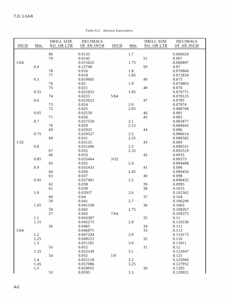
T.O. 1-1A-9
Table A-2. Decimal Equivalents
DRILL SIZE DECIMALS DRILL SIZE DECIMALSINCH Mm. NO. OR LTR OF AN INCH INCH Mm. NO. OR LTR OF AN INCH
80 0.0135 1.7 0.06692979 0.0145 51 0.067
1/64 0.015625 1.75 0.0688970.4 0.15748 50 0.07
78 0.016 1.8 0.07086677 0.018 1.85 0.072834
0.5 0.019685 49 0.07376 0.02 1.9 0.07480375 0.021 48 0.076
0.55 0.021653 1.95 0.07677174 0.0225 5/64 0.078125
0.6 0.023622 47 0.078573 0.024 2.0 0.0787472 0.025 2.05 0.080708
0.65 0.02559 46 0.08171 0.026 45 0.082
0.7 0.027559 2.1 0.08287770 0.028 2.15 0.08464569 0.02925 44 0.086
0.75 0.029527 2.2 0.08661468 0.031 2.25 0.088582
1/32 0.03125 43 0.0890.8 0.031496 2.3 0.090551
67 0.032 2.35 0.09251966 0.033 42 0.0935
0.85 0.033464 3/32 0.0937565 0.035 2.4 0.094488
0.9 0.035433 41 0.09664 0.036 2.45 0.09645663 0.037 40 0.098
0.95 0.037401 2.5 0.09842562 0.038 39 0.099561 0.039 38 0.1015
1.0 0.03937 2.6 0.10236260 0.04 37 0.10459 0.041 2.7 0.106299
1.05 0.041338 36 0.106558 0.042 2.75 0.10826757 0.043 7/64 0.109375
1.1 0.043307 35 0.111.15 0.045275 2.8 0.110236
56 0.0465 34 0.1113/64 0.046875 33 0.113
1.2 0.047244 2.9 0.1141731.25 0.049212 32 0.1161.3 0.051181 3.0 0.11811
55 0.052 31 0.121.35 0.053149 3.1 0.122047
54 0.055 1/8 0.1251.4 0.055118 3.2 0.1259841.45 0.057086 3.25 0.1279521.5 0.059055 30 0.1285
53 0.0595 3.3 0.129921
A-2

T.O. 1-1A-9
Table A-2. Decimal Equivalents - Continued
DRILL SIZE DECIMALS DRILL SIZE DECIMALSINCH Mm. NO. OR LTR OF AN INCH INCH Mm. NO. OR LTR OF AN INCH
1.55 0.061023 3.4 0.1338581/16 0.0625 29 0.136
1.6 0.062992 3.5 0.13779552 0.635 28 0.1405
1.65 0.06496 9/64 0.1406253.6 0.141732 A 0.234
27 0.144 15/64 0.2343753.7 0.145669 6.0 0.23622
26 0.147 B 0.2383.75 0.147637 6.1 0.240157
25 0.1495 C 0.2423.8 0.149606 6.2 0.244094
24 0.152 D 0.2463.9 0.153543 6.25 0.246062
23 0.154 6.3 0.2480315/32 0.15625 1/4 E 0.25
22 0.157 6.4 0.2519684.0 0.15748 6.5 0.255905
21 0.159 F 0.25720 0.161 6.6 0.259842
4.1 0.161417 G 0.2614.2 0.165354 6.7 0.263779
19 0.166 17/64 0.2656254.25 0.167322 6.75 0.2657474.3 0.169291 H 0.266
18 0.1695 6.8 0.26771611/64 0.171875 6.9 0.271653
17 0.173 I 0.2724.4 0.173228 7.0 0.27559
16 0.177 J 0.2774.5 0.177165 7.1 0.279527
15 0.18 K 0.2814.6 0.181102 9/32 0.28125
14 0.182 7.2 0.28346413 0.185 7.25 0.285432
4.7 0.185039 7.3 0.2874014.75 0.187007 L 0.29
3/16 0.1875 7.4 0.2913384.8 0.188976 M 0.295
12 0.189 7.5 0.29527511 0.191 19/64 0.296875
4.9 0.192913 7.6 0.29921210 0.1935 N 0.3029 0.196 7.7 0.303149
5.0 0.19685 7.75 0.3051178 0.199 7.8 0.307086
5.1 0.200787 7.9 0.3110237 0.201 5/16 0.3125
13/64 0.203125 8.0 0.314966 0.204 O 0.316
5.2 0.204724 8.1 0.3188975 0.2055 8.2 0.322834
5.25 0.206692 P 0.323
A-3
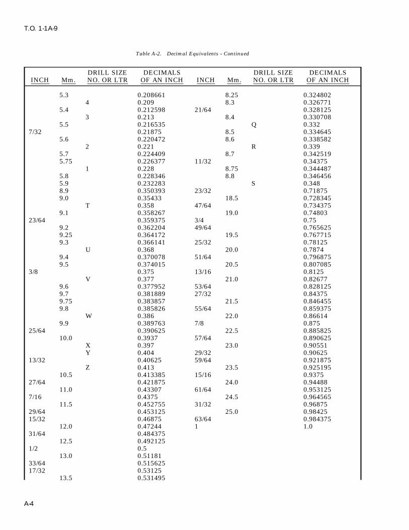
T.O. 1-1A-9
Table A-2. Decimal Equivalents - Continued
DRILL SIZE DECIMALS DRILL SIZE DECIMALSINCH Mm. NO. OR LTR OF AN INCH INCH Mm. NO. OR LTR OF AN INCH
5.3 0.208661 8.25 0.3248024 0.209 8.3 0.326771
5.4 0.212598 21/64 0.3281253 0.213 8.4 0.330708
5.5 0.216535 Q 0.3327/32 0.21875 8.5 0.334645
5.6 0.220472 8.6 0.3385822 0.221 R 0.339
5.7 0.224409 8.7 0.3425195.75 0.226377 11/32 0.34375
1 0.228 8.75 0.3444875.8 0.228346 8.8 0.3464565.9 0.232283 S 0.3488.9 0.350393 23/32 0.718759.0 0.35433 18.5 0.728345
T 0.358 47/64 0.7343759.1 0.358267 19.0 0.74803
23/64 0.359375 3/4 0.759.2 0.362204 49/64 0.7656259.25 0.364172 19.5 0.7677159.3 0.366141 25/32 0.78125
U 0.368 20.0 0.78749.4 0.370078 51/64 0.7968759.5 0.374015 20.5 0.807085
3/8 0.375 13/16 0.8125V 0.377 21.0 0.82677
9.6 0.377952 53/64 0.8281259.7 0.381889 27/32 0.843759.75 0.383857 21.5 0.8464559.8 0.385826 55/64 0.859375
W 0.386 22.0 0.866149.9 0.389763 7/8 0.875
25/64 0.390625 22.5 0.88582510.0 0.3937 57/64 0.890625
X 0.397 23.0 0.90551Y 0.404 29/32 0.90625
13/32 0.40625 59/64 0.921875Z 0.413 23.5 0.925195
10.5 0.413385 15/16 0.937527/64 0.421875 24.0 0.94488
11.0 0.43307 61/64 0.9531257/16 0.4375 24.5 0.964565
11.5 0.452755 31/32 0.9687529/64 0.453125 25.0 0.9842515/32 0.46875 63/64 0.984375
12.0 0.47244 1 1.031/64 0.484375
12.5 0.4921251/2 0.5
13.0 0.5118133/64 0.51562517/32 0.53125
13.5 0.531495
A-4

T.O. 1-1A-9
Table A-2. Decimal Equivalents - Continued
DRILL SIZE DECIMALS DRILL SIZE DECIMALSINCH Mm. NO. OR LTR OF AN INCH INCH Mm. NO. OR LTR OF AN INCH
35/64 0.54687514.0 0.55118
9/16 0.562514.5 0.570865
37/64 0.57812515.0 0.59055
19/32 0.5937539/64 0.609375
15.5 0.6102355/8 0.625
16.0 0.6299241/64 0.640625
16.5 0.64960521/32 0.65625
17.0 0.6692943/64 0.67187511/16 0.6875
17.5 0.68897545/64 0.703125
18.0 0.70866
A-5

T.O. 1-1A-9
Table A-3. Engineering Conversion Factors
LENGTH
1 inch = 2.54 Centimeters = 0.0833 Foot = 0.0278 Yard1 foot = 0.305 Meter = 0.333 Yard1 yard = 0.914 Meter = 3 Feet1 Rod = 16 1/2 Feet = 5 1/2 Yards1 Mile = 1.609 Kilometers = 5280 Feet = 1760 Yards1 Centimeter = 0.3937 Inch = 0.0328 Foot1 Meter = 39.37 Inches = 3.281 Feet = 1.094 Yards1 Kilometer = 1000 Meters = 3280.83 Feet = 1093.61 Yards = 0.62137 Mile
AREA
1 Sq. Inch = 6.452 Sq. Centimeters1 Sq. Foot = 144 Sq. Inches = 929.032 Sq. Centimeters1 Sq. Yard = 1296 Sq. Inches = 9 Sq. Feet = 0.836 Sq. Meter1 Sq. Rod = 272 1/4 Sq Feet = 30 1/4 Sq. Yards1 Acre = 43,560 Sq. Feet = 160 Sq. Rods1 Sq. Mile = 640 Acres1 Sq. Centimeter = 0.155 Sq. Inch1 Sq. Meter = 1550 Sq. Inches = 10.764 Sq. Feet = 1.196 Sq. Yards1 Sq. Kilometer = 0.3861 Sq. Miles = 247.104 Acres
VOLUME
1 Cu. Inch = 16.39 Cu. Centimeters = 0.00433 Gallons*1 Cu. Foot = 1728 Cu. Inches = 7.48 Gallons* = 28.317 Liters = 0.037 Cu. Yards1 Cu. Yard = 27 Cu. Feet = 0.7646 Cu. Meter = 202 Gallons*1 Cu. Centimeter = 0.001 Liter = 0.061 Cu. Inch1 Cu. Meter = 35.31 Cu. Feet = 1.308 Cu. Yards = 264.2 Gallons*1 Quart* = 0.25 Gallons* = 57.75 Cu. Inches = 0.946 Liter = 2 Pints*1 Gallon* = 0.832702 Imperial Gallon = 231 Cu. Inches = 0.1377 Cu. Feet = 3.785 Liters =
3785 Cu. Centimeters1 Gallon, Imperial = 1.20091 U.S. Gallons1 Barrel (Std.) = 31 1/2 Gallons1 Barrel (Oil) = 42 Gallons
*U.S. Measure
WEIGHT
1 Ounce = 16 Drams = 437.5 Grains = 0.0625 Pound = 28.35 Grams = 0.9155 Ounce (Troy)1 Pound = 16 0unces = 453.593 Grams = 0.453593 Kilogram1 Ton (Short) = 2000 Pounds = 907.185 Kilograms = 0.892857 Long Ton = 0.907185 Metric Ton1 Ton (Metric) = 2204.62 Pounds = 0.98421 Long Ton = 1.10231 Short Tons1 Ton (Long) = 2240 Pounds = 1016.05 Kilograms = 1.120 Short Tons = 1.01605 Metric Tons1 Gram = 15.43235 Grains = 0.001 Kilogram1 Kilogram = 2.20462 Pounds
COMPOUND UNITS
1 gram per square millimeter = 1.422 pounds per square inch1 kilogram per square millimeter = 1.422.32 pounds per square inch1 kilogram per square centimeter = 14.2232 pounds per square inch1 kilogram per square meter = 0.2048 pound per square foot
= 1.8433 pounds per square yard
A-6

T.O. 1-1A-9
Table A-3. Engineering Conversion Factors - Continued
COMPOUND UNITS (Cont)
1 kilogram meter = 7.2330 foot pounds1 kilogram per meter = 0.6720 pound per foot1 pound per square inch = 0.07031 kilogram per square centimeter1 pound per square foot = 0.0004882 kilogram per square centimeter1 pound per square foot = 0.006944 pound per square inch1 pound per cubic inch = 27679.7 kilograms per cubic meter1 pound per cubic foot = 16.0184 kilograms per cubic meter1 kilogram per cubic meter = 0.06243 pound per cubic foot1 foot per second = 0.30480 meter per second1 meter per second = 3.28083 feet per second1 meter per second = 2.23693 miles per hour
MULTIPLES
Circumference of Circle = Diameter X 3.1416Area of Circle = Square of Diameter X 0.7854, or
Square of Radius X 3.1416, orSquare of Circumference X 0.07958
Area of Triangle = Base X one-half altitudeSurface of Sphere = Circumference X diameter, or
Square of diameter X 3.1416Volume of Sphere = Surface X one-sixth diameter, or
Cube of diameter X 0.5236Area of Hexagon = Square of Diameter of Inscribed Circle X 0.866Area of Octagon = Square of Diameter of Inscribed Circle X 0.828
ENGINEERING UNITS
1 Horsepower = 1 kilowatt Hour =33,000 foot pounds per minute 1,000 watt hours550 foot pounds per second 1.34 horsepower hours746 watts 2,655,220 foot pounds0.746 kilowatts 3,412 heat units (B.T.U)
1 Horsepower Hour = 1 British Thermal Unit =0.746 Kilowatt hours 1,055 watt seconds1,980,000 foot pounds 778 foot pounds2,545 heat units (B.T.U) 0.000293 kilowatt hour
0.000393 horsepower hour
1 Kilowatt = 1 Watt =1,000 watts 1 joule per second1.34 horsepower 0.00134 horsepower737.3 foot pounds per second 3.3412 heat units (B.T.U.) per hour44.240 foot pounds per minute 0.7373 foot pounds per second56.9 heat units (B.T.U) per minute 44.24 foot pounds per minute
A-7

T.O. 1-1A-9
The following weights are approximate and variations must be expected in practice.
Table A-4. Table of Weights - Aluminum and Aluminum Alloy
Bars-Flat .0403 .........................................0.5676 1 x .049 .....................................0.18Size Lbs Per Linear Ft .0508 .........................................0.7158 1 x .058 .....................................0.2101/2 x 1 .......................................0.578 .0641 .........................................0.9026 1 x .065 .....................................0.231/2 x 2 .......................................1.174 .0808 .........................................1.1382 1 x .083 .....................................0.293/4 x 2 .......................................1.7604 .0907 .........................................1.2781 1 1/16 x .032.............................0.133/4 x 3 .......................................2.6408 .128 ...........................................1.8099 1 1/16 x .083.............................0.311 x 2 ..........................................2.3472 .156 ...........................................2.202 1 1/8 x .035..............................0.151 x 3 ..........................................3.5208 .1875 .........................................2.6481 1 1/8 x .049..............................0.201 1/2 x 2....................................3.5208 .250 ...........................................3.5215 1 1/8 x .058..............................0.241 3/4 x 3 1/2..............................7.1883 .375 ...........................................5.2822 1 1/8 x .065..............................0.272 x 3 ..........................................7.0416 .500 ...........................................7.212 1 3/16 x .083.............................0.352 3/4 x 4..................................12.9096 Tubing-Round 1 1/4 x .035..............................0.163 x 4 ........................................14.350 Size Lbs Per Linear Ft 1 1/4 x .049..............................0.2134
Bars-Hexagon 1/4 x .028 ..................................0.025 1 1/4 x .058..............................0.27Size Lbs Per Linear Ft 1/4 x .032 ..................................0.027 1 1/4 x .065..............................0.303/8 .............................................0.147 1/4 x .035 ..................................0.03 1 1/4 x .083..............................0.377/16 ...........................................0.20 1/4 x .049 ..................................0.036 1 5/16 x .083.............................0.391/2 .............................................0.262 1/4 x .058 ..................................0.044 1 3/8 x .032..............................0.179/16 ...........................................0.331 1/4 x .065 ..................................0.047 1 3/8 x .049..............................0.255/8 .............................................0.409 5/16 x .025 ................................0.027 1 3/8 x .058..............................0.293/4 .............................................0.639 5/16 x .028 ................................0.032 1 3/8 x .065..............................0.331 ................................................1.047 5/16 x .035 ................................0.039 1 3/8 x .083..............................0.411 1/4 ..........................................1.620 5/16 x .065 ................................0.061 1 3/8 x .120..............................0.581 1/2 ..........................................2.340 3/8 x .025 ..................................0.033 1 7/16 x .095.............................0.48
Rods-Round 3/8 x .028 ..................................0.037 1 1/2 x .035..............................0.19Size Lbs Per Linear Ft 3/8 x .035 ..................................0.0435 1 1/2 x .049..............................0.273/16 ...........................................0.032 3/8 x .042 ..................................0.053 1 1/2 x .058..............................0.321/4 .............................................0.058 3/8 x .049 ..................................0.063 1 1/2 x .065..............................0.365/16 ...........................................0.090 7/16 x .035 ................................0.054 1 1/2 x .083..............................0.453/8 .............................................0.129 7/16 x .049 ................................0.075 1 5/8 x .065..............................0.397/16 ...........................................0.176 1/2 x .032 ..................................0.056 1 5/8 x .125..............................0.721/2 .............................................0.230 1/2 x .035 ..................................0.063 1 11/14 x .095...........................0.589/16 ...........................................0.291 1/2 x .042 ..................................0.073 1 3/4 x .035...............................0.235/8 .............................................0.360 1/2 x .049 ..................................0.086 1 3/4 x .049...............................0.3211/14 .........................................0.435 1/2 x .065 ..................................0.11 1 3/4 x .065...............................0.39343/4 .............................................0.518 9/16 x .032 ................................0.067 1 3/4 x .083...............................0.5313/16 .........................................0.608 5/8 x .035 ..................................0.08 1 3/4 x .125...............................0.797/8 .............................................0.705 5/8 x .042 ..................................0.093 2 x .042 .....................................0.2915/16 .........................................0.809 5/8 x .049 ..................................0.11 1 7/8 x .049...............................0.341 ................................................0.921 5/8 x .058 ..................................0.13 2 x .049 .....................................0.361 1/4 ..........................................1.439 5/8 x .065 ..................................0.14 2 x .065 .....................................0.481 3/8 ..........................................1.741 11/16 x .049 ..............................0.105 2 x .083 .....................................0.611 1/2 ..........................................2.072 3/4 x .035 ..................................0.096 2 x .125 .....................................0.921 3/4 ..........................................2.820 3/4 x .049 ..................................0.1245 2 1/4 x .025...............................0.20522 ................................................3.683 3/4 x .058 ..................................0.15 2 1/2 x .065...............................0.612 1/2 ..........................................5.755 3/4 x .065 ..................................0.17 Tubing-Streamline2 3/4 ..........................................6.964 3/4 x .083 ..................................0.21 Size Lbs Per Linear Ft3 ................................................8.287 13/16 x .032 ..............................0.095 1.500 x .250 x .020...................0.0823 1/2 ........................................11.550 13/16 x .049 ..............................0.13 1.500 x .375 x .020...................0.0854 ..............................................15.200 7/8 x .028 ..................................0.09 1.625 x .375 x .025...................0.115
Sheets 7/8 x .035 ..................................0.11 1.875 x .375 x .035...................0.16Thickness Lbs Per Sq Ft 7/8 x .049 ..................................0.16 2.00 x .875 x .049....................0.27.0126 .........................................0.1797 15/16 x .032 ..............................0.11 2.01563 x .375 x .025...............0.12.016 ...........................................0.2253 15/16 x .049 ..............................0.17 2.625 x .375 x .035...................0.22.020 ...........................................0.2817 15/16 x .083 ..............................0.27 3.00 x .375 x .035....................0.25.0253 .........................................0.3570 1 x .032 .....................................0.12 3.125 x .375 x .032...................0.25.032 ...........................................0.4501 1 x .035 .....................................0.13 3.350 x 1.50 x .065...................0.61.0359 .........................................0.5055 1 x .042 .....................................0.16 4.0625 x 1.71 x .065.................0.73
A-8

T.O. 1-1A-9
Table A-5. Table of Weights - Brass
Bars-Flat 3/8 ...................................... 0.4493 13/16 .................................. 1.913Size Lbs Per Linear Ft 7/16 .................................... 0.6115 7/8 ...................................... 2.2181/8 x 1/2 ............................. 0.238 1/2 ...................................... 0.7987 18/14 .................................. 2.5461/8 x 3/4 ............................. 0.358 9/16 .................................... 1.001 1 ......................................... 2.8971/8 x 1 ................................ 0.475 5/8 ...................................... 1.248 1 1/8 ................................... 3.6671/8 x 1 3/4.......................... 0.815 11/16 .................................. 1.510 1 3/14 ................................. 4.0861/8 x 2 ................................ 0.935 3/4 ...................................... 1.797 1 1/4 ................................... 4.5276/32 x 1 .............................. 0.625 12/16 .................................. 2.109 1 5/16 ................................. 4.9913/16 x 3/4 ........................... 0.535 7/8 ...................................... 2.446 1 3/8 ................................... 5.4783/16 x 1 .............................. 0.715 15/16 .................................. 2.808 1 7/16 ................................. 5.9873/16 x 1 1/4........................ 0.895 1 ......................................... 3.195 1 1/2 ................................... 6.5193/16 x 1 1/2........................ 1.00 1 1/8 ................................... 4.043 1 9/16 ................................. 7.0733/16 x 1 3/4........................ 1.175 1 3/16 ................................. 4.505 1 5/8 ................................... 7.6513/16 x 2 .............................. 1.385 1 1/4 ................................... 4.992 1 11/16 ............................... 8.2503/16 x 2 1/2........................ 1.785 1 5/16 ................................. 5.503 1 3/4 ................................... 8.8733/16 x 3 .............................. 2.055 1 3/8 ................................... 6.040 1 13/14 ............................... 9.5181/4 x 1 ................................ 0.9575 1 1/2 ................................... 7.188 1 7/8 ................................. 10.191/4 x 1 1/8.......................... 1.075 1 9/16 ................................. 7.800 1 15/16 ............................. 10.881/4 x 1 1/4.......................... 1.185 1 5/8 ................................... 8.436 2 ....................................... 11.591/4 x 1 3/4.......................... 1.585 1 11/14 ............................... 9.097 2 1/4 ................................. 14.671/4 x 2 ................................ 1.885 1 3/4 ................................... 9.784 2 1/2 ................................. 18.111/4 x 2 1/2.......................... 2.375 1 13/16 ............................. 10.50 2 3/4 ................................. 21.911/4 x 3 ................................ 2.815 1 7/8 ................................. 11.23 2 7/8 ................................. 23.951/4 x 6 ................................ 5.65 1 15/16 ............................. 11.99 3 ....................................... 26.085/16 x 3/4 ........................... 0.957 2 ....................................... 12.78 3 1/2 ................................. 36.755/16 x 1 .............................. 1.075 2 1/2 ................................. 19.97 4 ....................................... 46.935/16 x 1 1/4........................ 1.475 3 ....................................... 26.41 5 ....................................... 74.255/16 x 1 1/2........................ 1.975 Bars-Square 6 ..................................... 108.255/16 x 1 3/4........................ 2.075 Size Lbs Per Linear Ft Sheet5/16 x 2 .............................. 2.375 3/16 .................................... 0.1297 Thickness Lbs Per Sq Ft5/16 x 2 1/2........................ 3.075 1/4 ...................................... 0.2306 .0031 .................................. 0.13935/16 x 3 .............................. 3.875 9/16 .................................... 0.3602 .0035 .................................. 0.15645/16 x 4 .............................. 5.125 3/8 ...................................... 0.5188 .004 .................................... 0.17565/16 x 6 .............................. 8.75 7/16 .................................... 0.7061 .0045 .................................. 0.19723/8 x 1 ................................ 1.285 1/2 ...................................... 0.9222 .005 .................................... 0.22143/8 x 1 1/4.......................... 1.575 5/8 ...................................... 1.441 .0056 .................................. 0.24863/8 x 1 1/2.......................... 2.00 3/4 ...................................... 2.075 .0063 .................................. 0.27923/8 x 1 3/4.......................... 2.275 1 ......................................... 3.689 .0071 .................................. 0.31353/8 x 2 ................................ 2.675 1 1/4 ................................... 5.764 .008 .................................... 0.35213/8 x 2 1/2.......................... 3.475 1 1/2 ................................... 8.300 .0089 .................................. 0.39533/8 x 3 ................................ 4.175 2 ....................................... 14.76 .010 .................................... 0.44393/8 x 4 ................................ 5.725 Rods-Round .0113 .................................. 0.49853/8 x 6 ................................ 8.325 Size Lbs Per Linear Ft .0126 .................................. 0.55981/2 x 1 ................................ 1.795 1/16 .................................... 0.01132 .0142 .................................. 0.62861/2 x 1 1/2.......................... 2.685 3/32 .................................... 0.03625 .0159 .................................. 0.70591/2 x 2 ................................ 3.675 1/8 ...................................... 0.04527 .0179 .................................. 0.79271/2 x 2 1/2.......................... 4.675 6/32 .................................... 0.0915 .0201 .................................. 0.89011/2 x 3 ................................ 5.675 3/16 .................................... 0.1019 .0226 .................................. 0.99951/2 x 4 ................................ 7.705 7/32 .................................... 0.1475 .0253 .................................. 1.1221/2 x 6 .............................. 11.10 1/4 ...................................... 0.1811 .0285 .................................. 1.2605/8 x 1 ................................ 2.156 9/32 .................................... 0.2375 .032 .................................... 1.4155/8 x 2 ................................ 4.250 9/14 .................................... 0.2829 .0359 .................................. 1.5893/4 x 1 ................................ 2.875 11/32 .................................. 0.3480 .0403 .................................. 1.7853/4 x 2 ................................ 5.750 3/8 ...................................... 0.4074 .0453 .................................. 2.0047/8 x 2 1/2.......................... 8.325 28/64 .................................. 0.4185 .0508 .................................. 2.2511 x 1 1/4............................. 4.525 12/32 .................................. 0.4866 .0571 .................................. 2.5271 x 2 ................................... 7.705 7/16 .................................... 0.5546 .0641 .................................. 2.838
Bars-Hexagon 1/2 ...................................... 0.7243 .072 .................................... 3.187Size Lbs Per Linear Ft 9/16 .................................... 0.9167 .0808 .................................. 3.5783/16 .................................... 0.1123 5/8 ...................................... 1.132 .0907 .................................. 4.0181/4 ...................................... 0.1997 11/14 .................................. 1.369 .1019 .................................. 4.5125/16 .................................... 0.3120 3/4 ...................................... 1.630 .1144 .................................. 5.067
A-9
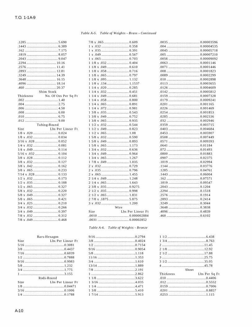
T.O. 1-1A-9
Table A-5. Table of Weights - Brass - Continued
.1285 .................................. 5.690 7/8 x .065 ........................... 0.609 .0035 .................................. 0.00003596
.1443 .................................. 6.389 1 x .032 .............................. 0.358 .004 .................................... 0.00004535
.162 .................................... 7.175 1 x .035 .............................. 0.391 .0045 .................................. 0.00005718
.1819 .................................. 8.057 1 x .049 .............................. 0.567 .005 .................................... 0.00007210
.2043 .................................. 9.047 1 x .065 .............................. 0.703 .0056 .................................. 0.00009092
.2294 ................................ 10.16 1 1/8 x .032........................ 0.404 .0063 .................................. 0.0001146
.2576 ................................ 11.41 1 1/8 x .049........................ 0.610 .0071 .................................. 0.0001446
.2893 ................................ 12.81 1 1/8 x .058........................ 0.716 .008 .................................... 0.0001823
.3249 ................................ 14.39 1 1/8 x .065........................ 0.797 .0089 .................................. 0.0002299
.3648 ................................ 16.15 1 1/8 x .095........................ 1.132 .010 .................................... 0.0002898
.4096 ................................ 18.14 1 1/8 x .134........................ 1.1537 .0113 .................................. 0.0003655
.460 .................................. 20.37 1 1/4 x .020........................ 0.285 .0126 .................................. 0.0004609Shim Stock 1 1/4 x .032........................ 0.451 .0142 .................................. 0.0005812
Thickness No. Of Ozs Per Sq Ft 1 1/4 x .049........................ 0.681 .0159 .................................. 0.0007328.002 .................................... 1.40 1 1/4 x .058........................ 0.800 .0179 .................................. 0.0009241.004 .................................... 2.75 1 1/4 x .065........................ 0.891 .0201 .................................. 0.001165.006 .................................... 4.50 1 1/4 x .072........................ 0.981 .0226 .................................. 0.001469.008 .................................... 6.00 1 3/8 x .035........................ 0.543 .0254 .................................. 0.001853.010 .................................... 6.75 1 3/8 x .049........................ 0.752 .0285 .................................. 0.002336.012 .................................... 9.00 1 3/8 x .065........................ 0.935 .032 .................................... 0.002946
Tubing-Round 1 1/2 x .032........................ 0.544 .0359 .................................. 0.003715Size Lbs Per Linear Ft 1 1/2 x .049........................ 0.823 .0403 .................................. 0.0046841/8 x .020 ........................... 0.024 1 1/2 x .065........................ 1.08 .0453 .................................. 0.0059071/8 x .032 ........................... 0.034 1 5/8 x .032........................ 0.590 .0508 .................................. 0.0074493/16 x .028 ......................... 0.052 1 5/8 x .049........................ 0.893 .0571 .................................. 0.0093931/4 x .032 ........................... 0.081 1 5/8 x .065........................ 1.173 .0641 .................................. 0.011841/4 x .049 ........................... 0.114 1 3/4 x .032........................ 0.636 .072 .................................... 0.014935/16 x .032 ......................... 0.104 1 3/4 x .049........................ 0.964 .0800 .................................. 0.018833/8 x .028 ........................... 0.112 1 3/4 x .065........................ 1.267 .0907 .................................. 0.023753/8 x .032 ........................... 0.127 1 7/8 x .049........................ 1.035 .1019 .................................. 0.029943/8 x .042 ........................... 0.162 2 x .032 .............................. 0.729 .1144 .................................. 0.037763/8 x .065 ........................... 0.233 2 x .035 .............................. 0.796 .1285 .................................. 0.047617/14 x .028 ......................... 0.133 2 x .065 .............................. 1.455 .1443 .................................. 0.060041/2 x .032 ........................... 0.173 2 1/4 x .049........................ 1.248 .162 .................................... 0.075711/2 x .035 ........................... 0.188 2 1/4 x .065........................ 1.643 .1819 .................................. 0.095471/2 x .065 ........................... 0.327 2 3/8 x .035........................ 0.9275 .2043 .................................. 0.12045/8 x .032 ........................... 0.220 2 1/2 x .035........................ 0.998 .2294 .................................. 0.15185/8 x .049 ........................... 0.327 2 1/2 x .065........................ 1.831 .2576 .................................. 0.19145/8 x .065 ........................... 0.421 2 7/8 x .1875...................... 5.875 .2893 .................................. 0.24143/4 x .025 ........................... 0.210 3 x .032 .............................. 1.200 .3249 .................................. 0.30443/4 x .032 ........................... 0.266 Wire .3648 .................................. 0.38383/4 x .049 ........................... 0.397 Size Lbs Per Linear Ft .4096 .................................. 0.48397/8 x .032 ........................... 0.312 .0010 .................................. 0.000002884 .460 .................................... 0.61027/8 x .049 ........................... 0.468 .0031 .................................. 0.00002852
Table A-6. Table of Weights - Bronze
Bars-Hexagon 9/16 ...........................................0.2794 1 1/2 ..........................................6.438Size Lbs Per Linear Ft 3/8 .............................................0.4024 1 3/4 ..........................................8.7635/16 ...........................................0.3081 1/2 .............................................0.7154 2 ..............................................11.453/8 .............................................0.4437 9/16 ...........................................0.9054 2 1/8 ........................................12.927/16 ...........................................0.6039 5/8 .............................................1.118 2 1/2 ........................................17.881/2 .............................................0.7888 11/16 .........................................1.353 3 ..............................................25.759/16 ...........................................0.9983 3/4 .............................................1.610 3 1/2 ........................................35.055/8 .............................................1.232 13/14 .........................................1.889 4 ..............................................45.783/4 .............................................1.775 7/8 .............................................2.191 Sheet1 ................................................3.155 1 ................................................2.862 Thickness Lbs Per Sq Ft
Rods-Round 1 1/8 ..........................................3.622 .010 ...........................................0.4406Size Lbs Per Linear Ft 1 3/16 ........................................4.035 .012 ...........................................0.55521/8 .............................................0.04471 1 1/4 ..........................................4.471 .0159 .........................................0.70063/16 ...........................................0.1006 1 3/8 ..........................................5.410 .0201 .........................................0.88571/4 .............................................0.1788 1 7/14 ........................................5.913 .0253 .........................................1.115
A-10

T.O. 1-1A-9
Table A-6. Table of Weights - Bronze - Continued
.032 ...........................................1.410 .050 ...........................................2.238 .0907 .........................................3.997
.0359 .........................................1.582 .0641 .........................................2.825 .1285 .........................................5.662
.0403 .........................................1.776 .0808 .........................................3.567
Table A-7. Table Of Weights - Copper
Bars-Flat Size Lbs Per Linear Ft 9/16 x .134 ................................0.704Size Lbs Per Linear Ft 1/8 x .020 ..................................0.026 5/8 x .032 ..................................0.2311/16 x 3/4 ..................................0.1809 1/8 x .025 ..................................0.030 5/8 x .035 ..................................0.2511/8 x 1 .......................................0.4823 1/8 x .028 ..................................0.033 5/8 x .042 ..................................0.2981/8 x 2 .......................................0.9646 1/8 x .032 ..................................0.036 5/8 x .049 ..................................0.3431/4 x 1 .......................................0.9646 1/8 x .049 ..................................0.045 5/8 x .065 ..................................0.4431/4 x 2 .......................................1.929 3/16 x .022 ................................0.044 5/8 x .083 ..................................0.5471/4 x 3 .......................................3.894 3/16 x .028 ................................0.055 5/8 x .120 ..................................0.7371/4 x 4 .......................................3.858 3/16 x .032 ................................0.061 11/14 x .120 ..............................0.8123/8 x 1 .......................................1.447 3/16 x .035 ................................0.065 3/4 x .025 ..................................0.2203/8 x 2 .......................................2.894 3/16 x .042 ................................0.075 3/4 x .028 ..................................0.2461/2 x 3/4 ....................................1.425 3/16 x .049 ................................0.083 3/4 x .032 ..................................0.2801/2 x 1 .......................................1.929 7/22 x .065 ................................0.132 3/4 x .035 ..................................0.3045/8 x 1 1/2.................................3.675 1/4 x .028 ..................................0.076 3/4 x .042 ..................................0.362
Rods-Round 1/4 x .032 ..................................0.085 3/4 x .049 ..................................0.418Size Lbs Per Linear Ft 1/4 x .035 ..................................0.092 3/4 x .058 ..................................0.4881/4 .............................................0.1894 1/4 x .042 ..................................0.106 3/4 x .065 ..................................0.5429/16 ...........................................0.2959 1/4 x .049 ..................................0.120 3/4 x .083 ..................................0.6733/8 .............................................0.4261 1/4 x .065 ..................................0.146 3/4 x .120 ..................................0.9207/16 ...........................................0.580 9/22 x .042 ................................0.122 3/4 x .134 ..................................1.001/2 .............................................0.7576 3/16 x .025 ................................0.088 13/16 x .042 ..............................0.3965/8 .............................................1.184 5/16 x .028 ................................0.097 13/16 x .049 ..............................0.4523/4 .............................................1.705 5/16 x .032 ................................0.110 7/8 x .028 ..................................0.2897/8 .............................................2.320 5/16 x .035 ................................0.119 7/8 x .032 ..................................0.3281 ................................................3.030 5/16 x .042 ................................0.139 7/8 x .035 ..................................0.3581 1/8 ..........................................3.835 5/16 x .049 ................................0.158 7/8 x .049 ..................................0.4921 1/4 ..........................................4.735 5/16 x .058 ................................0.180 7/8 x .058 ..................................0.5761 1/2 ..........................................6.818 5/16 x .065 ................................0.196 7/8 x .095 ..................................0.9011 3/4 ..........................................9.281 3/8 x .025 ..................................0.106 7/8 x .109 ..................................1.022 ..............................................12.12 3/8 x .028 ..................................0.118 7/8 x .120 ..................................1.102 1/2 ........................................18.94 3/8 x .032 ..................................0.134 1 x .025 .....................................0.2973 ..............................................27.27 3/8 x .035 ..................................0.145 1 x .028 .....................................0.331
Sheet 3/8 x .042 ..................................0.170 1 x .032 .....................................0.377Thickness Lbs Per Sq Ft 3/8 x .049 ..................................0.194 1 x .035 .....................................0.411.002 ...........................................0.125 3/8 x .065 ..................................0.245 1 x .042 .....................................0.489.003 ...........................................0.1434 3/8 x .083 ..................................0.295 1 x .049 .....................................0.567.005 ...........................................0.2312 3/8 x .095 ..................................0.325 1 x .065 .....................................0.739.006 ...........................................0.2914 7/16 x .032 ................................0.158 1 x .120 .....................................1.29.010 ...........................................0.4625 7/16 x .035 ................................0.171 1 1/16 x .032.............................0.403.0126 .........................................0.5827 7/16 x .042 ................................0.202 1 1/16 x .035.............................0.438.0142 .........................................0.6567 7/16 x .049 ................................0.232 1 1/8 x .032...............................0.425.0159 .........................................0.7353 7/16 x .065 ................................0.295 1 1/8 x .042...............................0.553.0201 .........................................0.9296 1/2 x .028 ..................................0.161 1 1/8 x .049...............................0.641.0226 .........................................1.0452 1/2 x .032 ..................................0.182 1 1/8 x .065...............................0.838.0253 .........................................1.170 1/2 x .035 ..................................0.198 1 1/8 x .148...............................1.759.032 ...........................................1.4799 1/2 x .042 ..................................0.234 1 3/16 x .032.............................0.453.0359 .........................................1.6602 1/2 x .049 ..................................0.269 1 1/4 x .032...............................0.474.0403 .........................................1.8637 1/2 x .058 ..................................0.312 1 1/4 x .035...............................0.517.0453 .........................................2.0950 1/2 x .065 ..................................0.344 1 1/4 x .049...............................0.716.0508 .........................................2.3493 1/2 x .120 ..................................0.554 1 1/4 x .065...............................0.937.0571 .........................................2.6407 1/2 x .134 ..................................0.596 1 1/4 x .072...............................1.03.0641 .........................................2.9644 9/16 x .032 ................................0.207 1 1/4 x .148...............................1.98.0808 .........................................3.7367 9/16 x .035 ................................0.225 1 5/16 x .032.............................0.498.0907 .........................................4.1946 9/16 x .042 ................................0.266 1 5/16 x .042.............................0.648.1285 .........................................5.9427 9/16 x .049 ................................0.306 1 5/16 x .049.............................0.758
Tubing-Round 9/16 x .120 ................................0.645 1 3/8 x .028...............................0.459
A-11

T.O. 1-1A-9
Table A-7. Table Of Weights - Copper - Continued
1 3/8 x .032...............................0.523 1 3/4 x .032...............................0.669 2 1/2 x .065...............................1.931 3/8 x .035...............................0.570 1 3/4 x .042...............................0.873 2 3/4 x .095...............................3.071 3/8 x .042...............................0.681 1 3/4 x .049...............................1.014 3 x .120 .....................................4.201 3/8 x .049...............................0.790 1 3/4 x .065...............................1.332 Wire1 3/8 x .065...............................1.036 1 3/4 x .148...............................2.884 Size No. of Ft Per Lb1 3/8 x .148...............................2.209 1 7/8 x .032...............................0.717 .020 .......................................826.91 7/16 x .035.............................0.597 1 7/8 x .042...............................0.937 .0253 .....................................516.71 1/2 x .032...............................0.571 1 7/8 x .049...............................1.088 .032 .......................................323.01 1/2 x .042...............................0.745 1 7/8 x .065...............................1.431 .0359 .....................................256.61 1/2 x .049...............................0.865 1 7/8 x .148...............................3.109 .0403 .....................................203.71 1/2 x .058...............................1.017 2 x .032 .....................................0.766 .0508 .....................................128.21 1/2 x .065...............................1.135 2 x .035 .....................................0.837 .0625 .......................................84.671 1/2 x .148...............................2.434 2 x .042 .....................................1.00 .064 .........................................80.751 5/8 x .032...............................0.620 2 x .049 .....................................1.163 .072 .........................................63.801 5/8 x .042...............................0.809 2 x .065 .....................................1.530 .0808 .......................................50.661 5/8 x .049...............................0.939 2 x .083 .....................................1.936 .0907 .......................................40.211 5/8 x .058...............................1.106 2 x .095 .....................................2.202 .1019 .......................................31.851 5/8 x .065...............................1.238 2 1/4 x .049...............................1.31 .1285 .......................................20.031 5/8 x .148...............................2.659 2 1/4 x .065...............................1.73 .2576 .........................................4.984
Table A-8. Table of Weights - Iron
Angle 5/16 x 3 x 3...............................6.1 .500 .........................................20.4Size Lbs Per Linear Ft 3/8 x 1 1/2 x 1 1/2 ....................3.35 Sheet-Galvanized1 1/16 x 1 x 1............................0.40 3/8 x 2 1/2 x 2 1/2 ....................5.90 Thickness Lbs Per Sq Ft1/8 x 3/4 x 3/4...........................0.59 5/8 x 6 x 6...............................24.2 .0156 .........................................0.7811/8 x 1 x 1.................................0.80 Sheet-Black .0188 .........................................0.9061/8 x 1 1/2 x 1 1/2 ....................1.23 Thickness Lbs Per Sq Ft .025 ...........................................1.1561/8 x 1 3/4 x 1 3/4 ....................1.44 .0156 .........................................0.625 .032 ...........................................1.4061/8 x 2 x 2.................................1.65 .0188 .........................................0.75 .0375 .........................................1.6563/16 x 1 x 1...............................1.16 .025 ...........................................1.00 .0438 .........................................1.90643/16 x 1 1/4 x 1 1/4 ..................1.48 .032 ...........................................1.25 .050 ...........................................2.1563/16 x 1 1/2 x 1 1/2 ..................1.80 .0375 .........................................1.50 .0625 .........................................2.623/16 x 1 1/2 x 2.........................2.12 .0438 .........................................1.723 .0938 .........................................3.96033/16 x 2 x 2 1/2.........................2.75 .050 ...........................................2.00 .125 ...........................................5.15633/16 x 2 1/2 x 2 1/2 ..................3.07 .0625 .........................................2.55 Sheet-Terne Plate1/4 x 1 1/4 x 1 1/4 ....................1.92 .0781 .........................................3.2 Size Lbs Per Sq Ft1/4 x 1 1/2 x 1 1/2 ....................2.34 .093 ...........................................3.757 .0156 .........................................0.63771/4 x 2 x 2.................................3.19 .125 ...........................................5.1 .0186 .........................................0.76851/4 x 2 1/2 x 2 1/2 ....................4.10 .156 ...........................................6.4 .025 ...........................................1.0221/4 x 3 x 3.................................4.9 .1875 .........................................7.56 .0313 .........................................1.27951/4 x 4 x 4.................................6.6 .250 .........................................10.2 .037 ...........................................1.53295/16 x 2 1/2 x 3.........................5.6 .375 .........................................15.178 .050 ...........................................2.044
Table A-9. Table of Weights - Lead
Sheet 1/16 ...........................................4.25 1/8 .............................................7.812Thickness Lbs Per Sq Ft 3/52 ...........................................6.031 3/16 .........................................11.7201/32 ...........................................2.10
Table A-10. Table of Weights - Magnesium and Magnesium Alloy
Bars-Flat 2 x 3 ..........................................4.535 3/4 .............................................0.412Size Lbs Per Linear Ft 2 3/4 x 4....................................8.320 1 ................................................0.6741/2 x 1 .......................................0.372 3 x 4 ..........................................9.240 1 1/4 ..........................................1.0431/2 x 2 .......................................0.756 Bars-Hexagon 1 1/2 ..........................................1.5103/4 x 2 .......................................1.135 Size Lbs Per Linear Ft Rods-Round3/4 x 3 .......................................1.700 3/8 .............................................0.095 Size Lbs Per Linear Ft1 x 2 ..........................................1.513 7/16 ...........................................0.129 3/16 ...........................................0.0211 x 3 ..........................................2.270 1/2 .............................................0.169 1/4 .............................................0.0371 1/2 x 2....................................2.290 9/16 ...........................................0.213 3/16 ...........................................0.0581 3/4 x 3 1/2..............................4.630 5/8 .............................................0.263 3/8 .............................................0.083
A-12

T.O. 1-1A-9
Table A-10. Table of Weights - Magnesium and Magnesium Alloy - Continued
7/16 ...........................................0.114 1 3/4 ..........................................1.818 .032 ...........................................0.2901/2 .............................................0.148 2 ................................................2.385 .0359 .........................................0.32583/16 ...........................................0.188 2 1/2 ..........................................3.710 .0403 .........................................0.3665/8 .............................................0.232 2 3/4 ..........................................4.480 .0508 .........................................0.46211/16 .........................................0.280 3 ................................................5.340 .0641 .........................................0.5823/4 .............................................0.334 3 1/2 ..........................................7.450 .0808 .........................................0.73313/16 .........................................0.392 4 ................................................9.800 .128 ...........................................1.1677/8 .............................................0.454 Sheets .0907 .........................................1.82315/16 .........................................0.522 Thickness Lbs Per Sq Ft .156 ...........................................1.4181 ................................................0.593 .0126 .........................................0.1158 .1875 .........................................1.7081 1/4 ..........................................0.927 .020 ...........................................0.1814 .250 ...........................................2.2701 3/8 ..........................................1.122 .016 ...........................................0.1451 .375 ...........................................3.4051 1/2 ..........................................1.348 .0253 .........................................0.230 .500 ...........................................4.650
Table A-11. Table of Weights - Nickel Chromium Iron Alloy (Inconel)
Rods-Round .250 .........................................11.12 3/4 x .065 ..................................0.519Size Lbs Per Linear Ft Tubing 7/8 x .035 ..................................0.3431/4 .............................................0.182 Size Lbs Per Linear Ft 7/8 x .049 ..................................0.4723/16 ...........................................0.285 1/4 x .028 ..................................0.071 7/8 x .058 ..................................0.5523/8 .............................................0.409 1/4 x .035 ..................................0.088 7/8 x .065 ..................................0.6131/2 .............................................0.728 1/4 x .049 ..................................0.113 1 x .035 .....................................0.3933/4 .............................................1.638 1/4 x .065 ..................................0.139 1 x .049 .....................................0.5431 ................................................2.912 5/16 x .028 ................................0.091 1 x .058 .....................................0.6361 1/4 ..........................................4.55 5/16 x .035 ................................0.113 1 x .065 .....................................0.7081 1/2 ..........................................6.553 5/16 x .049 ................................0.150 1 1/4 x .049...............................0.6862 ..............................................11.651 5/16 x .065 ................................0.188 1 1/4 x .065...............................0.8972 1/2 ........................................18.203 3/8 x .028 ..................................0.113 1 3/8 x .049...............................0.757
Sheets 3/8 x .035 ..................................0.139 1 3/8 x .065...............................0.988Thickness Lbs Per Sq Ft 3/8 x .049 ..................................0.188 1 1/2 x .035...............................0.597.018 ...........................................0.84 3/8 x .058 ..................................0.217 1 1/2 x .049...............................0.828.025 ...........................................1.11 3/8 x .065 ..................................0.236 1 1/2 x .065...............................1.09.032 ...........................................1.39 1/2 x .035 ..................................0.191 1 3/4 x .049...............................0.969.037 ...........................................1.65 1/2 x .049 ..................................0.257 1 3/4 x .065...............................1.28.043 ...........................................1.91 1/2 x .058 ..................................0.299 2 x .049 .....................................1.11.050 ...........................................2.22 1/2 x .065 ..................................0.329 2 x .065 .....................................1.46.0625 .........................................2.76 5/8 x .049 ..................................0.329 2 1/4 x .049...............................1.26.093 ...........................................4.14 5/8 x .065 ..................................0.424 2 1/4 x .065...............................1.65.125 ...........................................5.56 3/4 x .035 ..................................0.292 2 1/2 x .049...............................1.40.156 ...........................................6.94 3/4 x .049 ..................................0.400 2 1/2 x .065...............................1.84.1875 .........................................8.32 3/4 x .058 ..................................0.468 3 1/4 x .120...............................4.38
Table A-12. Table of Weights - Nickel Copper Alloy
Rods-Round 1 ................................................3.044 Thickness Lbs Per Sq FtSize Lbs Per Linear Ft 1 1/4 ..........................................4.756 .018 ...........................................0.861/4 .............................................0.190 1 1/2 ..........................................6.849 .025 ...........................................1.153/16 ...........................................0.309 2 ..............................................12.178 .032 ...........................................1.443/8 .............................................0.428 2 1/2 ........................................19.027 .037 ...........................................1.721/2 .............................................0.761 Sheets .125 ...........................................5.753/4 .............................................1.172
Table A-13. Table of Weights - Steel
Bars-Flat 1/14 x 3 .....................................0.638 3/16 x 1/2 ..................................0.319Size Lbs Per Linear Ft 1/8 x 1/2 ....................................0.2125 3/16 x 3/4 ..................................0.4781/14 x 1/2 ..................................0.106 1/8 x 3/4 ....................................0.3188 3/16 x 1 .....................................0.6381/14 x 3/4 ..................................0.1594 1/8 x 1 .......................................0.425 3/16 x 1 1/4...............................0.7971/14 x 1 .....................................0.212 1/8 x 1 1/2.................................0.638 3/16 x 1 1/2...............................0.9561/14 x 1 1/2...............................0.319 1/8 x 2 .......................................0.850 3/16 x 2 .....................................1.281/14 x 2 .....................................0.425 1/8 x 2 1/2.................................1.06 3/16 x 2 1/2...............................1.591/14 x 2 1/2...............................0.531 1/8 x 3 .......................................1.27 3/16 x 3 .....................................1.91
A-13

T.O. 1-1A-9
Table A-13. Table of Weights - Steel - Continued
1/4 x 1/2 ....................................0.425 1 1/4 x 3..................................12.75 5/32 ...........................................0.0651/4 x 3/4 ....................................0.636 1 1/4 x 4..................................17.00 3/16 ...........................................0.0941/4 x 1 .......................................0.850 1 1/2 x 2..................................10.20 7/32 ...........................................0.1281/4 x 1 1/4.................................1.06 1 1/2 x 3..................................15.30 1/4 .............................................0.1671/4 x 1 1/2.................................1.28 1 1/2 x 5..................................25.50 9/32 ...........................................0.2111/4 x 1 3/4.................................1.49 2 x 2 1/2..................................17.00 5/16 ...........................................0.2611/4 x 2 .......................................1.70 2 x 3 ........................................20.40 11/22 .........................................0.3161/4 x 2 1/2.................................2.13 2 x 4 ........................................27.20 3/8 .............................................0.3761/4 x 3 .......................................2.55 2 1/2 x 3..................................25.50 7/16 ...........................................0.5113/16 x 1/2 ..................................0.531 3 x 4 ........................................40.80 1/2 .............................................0.6683/16 x 3/4 ..................................0.797 Bars-Hexagon 9/16 ...........................................0.8455/16 x 1 .....................................1.06 Size Lbs Per Linear Ft 5/8 .............................................1.0435/16 x 1 1/4...............................1.33 1/4 .............................................0.195 11/16 .........................................1.2625/16 x 1 1/2...............................1.59 5/16 ...........................................0.29 3/4 .............................................1.5025/16 x 1 3/4...............................1.86 3/8 .............................................0.43 13/16 .........................................1.7635/16 x 2 .....................................2.13 7/16 ...........................................0.56 7/8 .............................................2.0445/16 x 2 1/4...............................2.39 1/2 .............................................0.73 15/16 .........................................2.3475/16 x 2 1/2...............................2.66 9/16 ...........................................0.93 1 ................................................2.6705/16 x 2 3/4...............................2.92 5/8 .............................................1.15 1 1/16 ........................................3.0155/16 x 3 .....................................3.19 11/16 .........................................1.40 1 1/8 ..........................................3.3803/8 x 1/2 ....................................0.638 3/4 .............................................1.66 1 3/16 ........................................3.7663/8 x 1 .......................................1.28 13/16 .........................................1.91 1 1/4 ..........................................4.1723/8 x 1 1/4.................................1.59 7/8 .............................................2.25 1 3/8 ..........................................5.0493/8 x 1 1/2.................................1.91 13/16 .........................................2.58 1 7/16 ........................................5.5183/8 x 2 .......................................2.55 1 ................................................2.94 1 1/2 ..........................................6.0083/8 x 2 1/2.................................3.19 1 1/16 ........................................3.33 1 5/8 ..........................................7.0513/8 x 3 .......................................3.83 1 1/8 ..........................................3.73 1 3/4 ..........................................8.1783/8 x 3 1/2.................................4.46 1 1/4 ..........................................4.60 1 7/8 ..........................................9.3883/8 x 4 .......................................5.10 1 5/16 ........................................5.07 2 ..............................................10.683/8 x 6 .......................................7.65 1 3/8 ..........................................5.57 2 1/4 ........................................13.521/2 x 1 .......................................1.70 1 1/2 ..........................................6.62 2 5/16 ......................................14.281/2 x 1 1/4.................................2.13 1 3/4 ..........................................9.00 2 3/8 ........................................15.061/2 x 1 1/2.................................2.55 2 ..............................................11.78 2 1/2 ........................................16.691/2 x 2 .......................................3.40 Bars-Square 2 3/4 ........................................20.191/2 x 2 1/2.................................4.25 Size Lbs Per Linear Ft 3 ..............................................24.031/2 x 3 .......................................5.10 1/8 .............................................0.053 3 1/4 ........................................28.211/2 x 3 1/2.................................5.95 3/16 ...........................................0.120 3 1/2 ........................................32.711/2 x 4 .......................................6.80 1/4 .............................................0.212 3 3/4 ........................................37.551/2 x 4 1/2.................................7.65 5/16 ...........................................0.332 4 ..............................................42.731/2 x 5 .......................................8.50 3/8 .............................................0.478 4 1/2 ........................................54.071/2 x 6 .....................................10.20 7/16 ...........................................0.651 5 ..............................................66.765/8 x 2 .......................................4.25 1/2 .............................................0.850 5 1/2 ........................................80.785/8 x 2 1/2.................................5.31 9/16 ...........................................1.076 6 ..............................................96.135/8 x 3 .......................................6.38 5/8 .............................................1.328 7 ............................................130.85/8 x 3 1/2.................................7.44 3/4 .............................................1.913 8 ............................................170.95/8 x 4 .......................................8.50 7/8 .............................................2.603 Sheets5/8 x 6 .....................................12.75 1 ................................................3.40 Thickness Lbs Per Sq Ft3/4 x 1 .......................................2.55 1 1/8 ..........................................4.303 .0156 .........................................0.63773/4 x 1 1/2.................................3.85 1 1/4 ..........................................5.313 .020 ...........................................0.89523/4 x 2 .......................................5.10 1 5/16 ........................................5.857 .025 ...........................................1.0223/4 x 2 1/2.................................6.38 1 3/8 ..........................................6.428 .03125 .......................................1.27953/4 x 3 .......................................7.65 1 1/2 ..........................................7.650 .0375 .........................................1.53293/4 x 4 .....................................10.20 1 3/4 ........................................10.41 .050 ...........................................2.0443/4 x 5 .....................................12.75 2 ..............................................13.60 .0625 .........................................2.55493/4 x 6 .....................................15.30 2 1/4 ........................................17.21 .0781 .........................................3.19281 x 2 ..........................................6.80 2 1/2 ........................................21.25 .093 ...........................................3.83441 x 2 1/2....................................8.50 3 ..............................................30.60 .109 ...........................................4.45571 x 3 ........................................10.20 Rods-Rounds .125 ...........................................5.10961 x 4 ........................................13.60 Size Lbs Per Linear Ft .156 ...........................................6.3771 x 5 ........................................17.00 1/16 ...........................................0.010 .1875 .........................................7.68511 x 6 ........................................20.40 3/32 ...........................................0.023 .250 .........................................10.2191 1/4 x 2....................................8.50 1/8 .............................................0.042 Tubing-Round
A-14

T.O. 1-1A-9
Table A-13. Table of Weights - Steel - Continued
Size Lbs Per Linear Ft 13/16 x .065 ..............................0.5184 1 1/2 x .065...............................0.99513/16 x .028 ................................0.0476 7/8 x .028 ..................................0.2530 1 1/2 x .083...............................1.2553/16 x .035 ................................0.0569 7/8 x .035 ..................................0.3137 1 1/2 x .095...............................1.4241/4 x .028 ..................................0.0663 7/8 x .049 ..................................0.4318 1 1/2 x .120...............................1.7671/4 x .035 ..................................0.0803 7/8 x .058 ..................................0.5056 1 1/2 x .1875.............................2.6261/4 x .049 ..................................0.1051 7/8 x .065 ..................................0.5617 1 9/16 x .049.............................0.79121/4 x .058 ..................................0.1188 7/8 x .095 ..................................0.7906 1 9/16 x .065.............................1.0381/4 x .065 ..................................0.1283 7/8 x .120 ..................................0.9666 1 9/16 x .095.............................1.4875/16 x .028 ................................0.0850 15/16 x .035 ..............................0.3370 1 5/8 x .049...............................0.82395/16 x .035 ................................0.1036 15/16 x .049 ..............................0.4645 1 5/8 x .058...............................0.96975/16 x .049 ................................0.1378 15/16 x .065 ..............................0.6051 1 5/8 x .065...............................1.0825/16 x .058 ................................0.1575 15/16 x .083 ..............................0.7567 1 5/8 x .083...............................1.3655/16 x .065 ................................0.1716 1 x .028 .....................................0.2904 1 5/8 x .095...............................1.5515/16 x .095 ................................0.2204 1 x .035 .....................................0.3603 1 5/8 x .120...............................1.9273/8 x .028 ..................................0.1037 1 x .049 .....................................0.4972 1 11/16 x .049...........................0.85663/8 x .035 ..................................0.1270 1 x .058 .....................................0.5829 1 11/16 x .065...........................1.1253/8 x .049 ..................................0.1704 1 x .065 .....................................0.6484 1 11/16 x .095...........................1.6143/8 x .058 ..................................0.1962 1 x .083 .....................................0.8120 1 3/4 x .035...............................0.64043/8 x .065 ..................................0.2150 1 x .095 .....................................0.9173 1 3/4 x .049...............................0.88923/8 x .083 ..................................0.2586 1 x .120 .....................................1.127 1 3/4 x .058...............................1.0473/8 x .095 ..................................0.2838 1 1/16 x .035.............................0.3837 1 3/4 x .065...............................1.1697/16 x .028 ................................0.1223 1 1/16 x .049.............................0.5298 1 3/4 x .083...............................1.4767/16 x .035 ................................0.1503 1 1/16 x .065.............................0.6917 1 3/4 x .095...............................1.6777/16 x .049 ................................0.2030 1 1/8 x .035...............................0.4070 1 3/4 x .120...............................2.0877/16 x .065 ................................0.2583 1 1/8 x .049...............................0.5625 1 3/4 x .125...............................2.1677/16 x .083 ................................0.3139 1 1/8 x .058...............................0.6603 1 3/4 x .1875.............................3.1267/16 x .095 ................................0.3471 1 1/8 x .065...............................0.7351 1 13/16 x .049...........................0.92191/2 x .028 ..................................0.1410 1 1/8 x .083...............................0.9227 1 13/16 x .065...........................1.2121/2 x .035 ..................................0.1736 1 1/8 x .095...............................1.044 1 13/16 x .095...........................1.7411/2 x .042 ..................................0.2052 1 1/8 x .120...............................1.287 1 7/8 x .049...............................0.95461/2 x .049 ..................................0.2358 1 3/16 x .035.............................0.4304 1 7/8 x .058...............................1.1241/2 x .058 ..................................0.2735 1 3/16 x .049.............................0.5952 1 7/8 x .065...............................1.2551/2 x .065 ..................................0.3017 1 3/16 x .065.............................0.7784 1 7/8 x .095...............................1.8041/2 x .083 ..................................0.3693 1 3/16 x .095.............................1.107 1 7/8 x .120...............................2.2471/2 x .095 ..................................0.4105 1 3/16 x .120.............................1.367 1 15/16 x .049...........................0.98739/16 x .035 ................................0.1969 1 1/4 x .028...............................0.3650 1 15/16 x .065...........................1.2999/16 x .049 ................................0.2684 1 1/4 x .035...............................0.4537 1 15/16 x .095...........................1.8679/16 x .065 ................................0.3450 1 1/4 x .049...............................0.6279 2 x .035 .....................................0.73389/16 x .095 ................................0.4738 1 1/4 x .058...............................0.7376 2 x .049 .....................................1.0205/8 x .028 ..................................0.1783 1 1/4 x .065...............................0.8218 2 x .058 .....................................1.2025/8 x .035 ..................................0.2203 1 1/4 x .083...............................1.034 2 x .065 .....................................1.3405/8 x .049 ..................................0.3011 1 1/4 x .095...............................1.171 2 x .083 .....................................1.6985/8 x .058 ..................................0.3509 1 1/4 x .120...............................1.447 2 x .095 .....................................1.9315/8 x .065 ..................................0.3883 1 1/4 x .125...............................1.500 2 x .120 .....................................2.4075/8 x .083 ..................................0.480 1 1/4 x .134...............................1.595 2 x .125 .....................................2.5015/8 x .095 ..................................0.5372 1 5/16 x .035.............................0.4770 2 x .1875 ...................................3.6265/8 x .120 ..................................0.6465 1 5/16 x .049.............................0.6605 2 1/8 x .035...............................0.780411/14 x .035 ..............................0.2437 1 5/16 x .065.............................0.8651 2 1/8 x .049...............................1.08511/14 x .049 ..............................0.3338 1 5/16 x .095.............................1.234 2 1/8 x .058...............................1.27911/14 x .065 ..............................0.4317 1 5/16 x .120.............................1.527 2 1/8 x .065...............................1.42911/14 x .095 ..............................0.6005 1 3/8 x .035...............................0.5004 2 1/8 x .095...............................2.0573/4 x .028 ..................................0.2157 1 3/8 x .049...............................0.6932 2 1/8 x .120...............................2.5673/4 x .035 ..................................0.2670 1 3/8 x .058...............................0.8150 2 1/4 x .035...............................0.82713/4 x .049 ..................................0.3665 1 3/8 x .065...............................0.9085 2 1/4 x .049...............................1.1513/4 x .058 ..................................0.4282 1 3/8 x .083...............................1.144 2 1/4 x .058...............................1.3563/4 x .065 ..................................0.4750 1 3/8 x .120...............................1.607 2 1/4 x .065...............................1.5153/4 x .083 ..................................0.5906 1 7/16 x .049.............................0.7259 2 1/4 x .083...............................1.9193/4 x .095 ..................................0.6639 1 7/16 x .065.............................0.9518 2 1/4 x .095...............................2.1843/4 x .120 ..................................0.8066 1 7/16 x .095.............................1.361 2 1/4 x .120...............................2.72713/14 x .035 ..............................0.2903 1 1/2 x .035...............................0.5470 2 1/4 x .125...............................2.83413/16 x .049 ..............................0.3991 1 1/2 x .040...............................0.7585 2 1/4 x .1875.............................4.12613/16 x .058 ..............................0.4669 1 1/2 x .058...............................0.8923 2 3/8 x .049...............................1.216
A-15
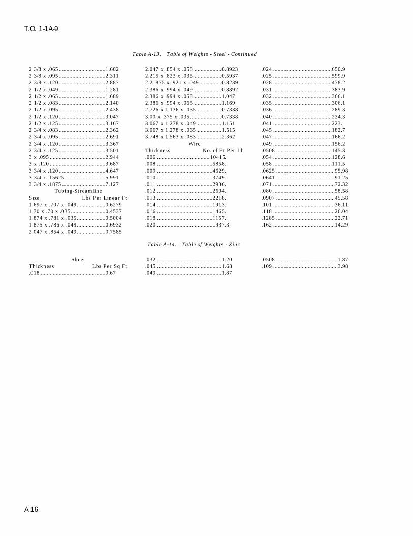
T.O. 1-1A-9
Table A-13. Table of Weights - Steel - Continued
2 3/8 x .065...............................1.602 2.047 x .854 x .058...................0.8923 .024 .......................................650.92 3/8 x .095...............................2.311 2.215 x .823 x .035...................0.5937 .025 .......................................599.92 3/8 x .120...............................2.887 2.21875 x .921 x .049...............0.8239 .028 .......................................478.22 1/2 x .049...............................1.281 2.386 x .994 x .049...................0.8892 .031 .......................................383.92 1/2 x .065...............................1.689 2.386 x .994 x .058...................1.047 .032 .......................................366.12 1/2 x .083...............................2.140 2.386 x .994 x .065...................1.169 .035 .......................................306.12 1/2 x .095...............................2.438 2.726 x 1.136 x .035.................0.7338 .036 .......................................289.32 1/2 x .120...............................3.047 3.00 x .375 x .035.....................0.7338 .040 .......................................234.32 1/2 x .125...............................3.167 3.067 x 1.278 x .049.................1.151 .041 .......................................223.2 3/4 x .083...............................2.362 3.067 x 1.278 x .065.................1.515 .045 .......................................182.72 3/4 x .095...............................2.691 3.748 x 1.563 x .083.................2.362 .047 .......................................166.22 3/4 x .120...............................3.367 Wire .049 .......................................156.22 3/4 x .125...............................3.501 Thickness No. of Ft Per Lb .0508 .....................................145.33 x .095 .....................................2.944 .006 ...................................10415. .054 .......................................128.63 x .120 .....................................3.687 .008 .....................................5858. .058 .......................................111.53 3/4 x .120...............................4.647 .009 .....................................4629. .0625 .......................................95.983 3/4 x .15625...........................5.991 .010 .....................................3749. .0641 .......................................91.253 3/4 x .1875.............................7.127 .011 .....................................2936. .071 .........................................72.32
Tubing-Streamline .012 .....................................2604. .080 .........................................58.58Size Lbs Per Linear Ft .013 .....................................2218. .0907 .......................................45.581.697 x .707 x .049...................0.6279 .014 .....................................1913. .101 .........................................36.111.70 x .70 x .035.......................0.4537 .016 .....................................1465. .118 .........................................26.041.874 x .781 x .035...................0.5004 .018 .....................................1157. .1285 .......................................22.711.875 x .786 x .049...................0.6932 .020 .......................................937.3 .162 .........................................14.292.047 x .854 x .049...................0.7585
Table A-14. Table of Weights - Zinc
Sheet .032 ...........................................1.20 .0508 .........................................1.87Thickness Lbs Per Sq Ft .045 ...........................................1.68 .109 ...........................................3.98.018 ...........................................0.67 .049 ...........................................1.87
A-16

T.O. 1-1A-9
Table A-15. Temperature Conversion Chart
A-17

T.O. 1-1A-9
Table A-16. Standard Bend Radii for 90o Cold Forming-Flat Sheet
A-18

T.O. 1-1A-9
Table A-16. Standard Bend Radii for 90o Cold Forming-Flat Sheet - Continued
Table A-17. Metal Bending and Bend Radii Bend Allowances Sheet Metal Bend Allowances Per Degree of Bend Aluminum Alloys
Stock Thickness
BENDRADIUS 0.022 0.032 0.040 0.051 0.064 0.091 0.128 0.187
Bend Allowance per One Degree
1/32 0.00072 0.00079 0.00086 0.00094 0.00104 0.00125 0.00154 0.002001/16 0.00126 0.00135 0.00140 0.00149 0.00159 0.00180 0.00209 0.002553/32 0.00180 0.00188 0.00195 0.00203 0.00213 0.00234 0.00263 0.003091/8 0.00235 0.00243 0.00249 0.00258 0.00268 0.00289 0.00317 0.00364
5/32 0.00290 0.00297 0.00304 0.00312 0.00322 0.00343 0.00372 0.004183/16 0.00344 0.00352 0.00358 0.00367 0.00377 0.00398 0.00426 0.004737/32 0.00398 0.00406 0.00412 0.00421 0.00431 0.00452 0.00481 0.005271/4 0.00454 0.00461 0.00467 0.00476 0.00486 0.00507 0.00535 0.00582
9/32 0.00507 0.00515 0.00521 0.00530 0.00540 0.00561 0.00590 0.006365/16 0.00562 0.00570 0.00576 0.00584 0.00595 0.00616 0.00644 0.0069111/32 0.00616 0.00624 0.00630 0.00639 0.00649 0.00670 0.00699 0.007453/8 0.00671 0.00679 0.00685 0.00693 0.00704 0.00725 0.00753 0.00800
13/32 0.00725 0.00733 0.00739 0.00748 0.00758 0.00779 0.00808 0.008547/16 0.00780 0.00787 0.00794 0.00802 0.00812 0.00834 0.00862 0.0090815/32 0.00834 0.00842 0.00848 0.00857 0.00867 0.00888 0.00917 0.009631/2 0.00889 0.00896 0.00903 0.00911 0.00921 0.00943 0.00971 0.01017
17/32 0.00943 0.00951 0.00957 0.00966 0.00976 0.00997 0.01025 0.010729/16 0.00998 0.01005 0.01012 0.01020 0.01030 0.01051 0.01080 0.0112619/32 0.01051 0.01058 0.01065 0.01073 0.01083 0.01105 0.01133 0.01179
A-19

T.O. 1-1A-9
Table A-17. Metal Bending and Bend Radii Bend Allowances Sheet Metal Bend Allowances Per Degree of Bend Aluminum Alloys -Continued
Stock Thickness
BENDRADIUS 0.022 0.032 0.040 0.051 0.064 0.091 0.128 0.187
Bend Allowance per One Degree
5/8 0.01107 0.01114 0.01121 0.01129 0.01139 0.01160 0.01189 0.01235
21/32 0.01161 0.01170 0.01175 0.01183 0.01193 0.01214 0.01245 0.0128911/16 0.01216 0.01223 0.01230 0.01238 0.01248 0.01268 0.01298 0.0134423/32 0.01269 0.01276 0.01283 0.01291 0.01301 0.01322 0.01351 0.013973/4 0.01324 0.01332 0.01338 0.01347 0.01357 0.01378 0.01407 0.01453
Example: To determine bend allowanceGiven: Stock = 0.064 aluminum alloy, Bend Radius = 1/8, Bend Angle = 50o
Find bend allowance for 1o in column for 0.064 Aluminum opposite 1/8 in column ‘‘Bend Radius’’.Multiply this bend allowance (0.00268 in this case) by the number of degrees of the desired bend angle:
0.00268 x 50 = 0.1340 = total bend allowance to be added to the length of the straight sides of thepart to determine the total length of the material needed.
A-20

T.O. 1-1A-9
Table A-18. Bend Set Back Chart
A-21
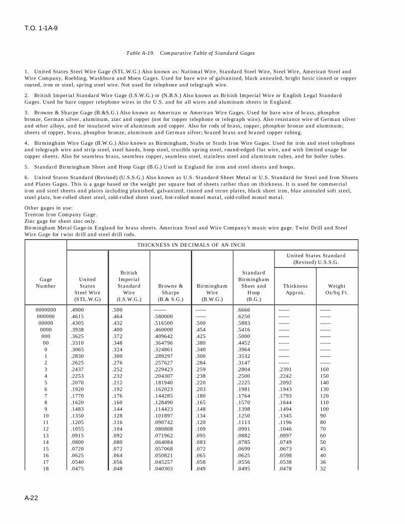
T.O. 1-1A-9
Table A-19. Comparative Table of Standard Gages
1. United States Steel Wire Gage (STL.W.G.) Also known as: National Wire, Standard Steel Wire, Steel Wire, American Steel andWire Company, Roebling, Washburn and Moen Gages. Used for bare wire of galvanized, black annealed, bright basic tinned or coppercoated, iron or steel, spring steel wire. Not used for telephone and telegraph wire.
2. British Imperial Standard Wire Gage (I.S.W.G.) or (N.B.S.) Also known as British Imperial Wire or English Legal StandardGages. Used for bare copper telephone wires in the U.S. and for all wires and aluminum sheets in England.
3. Browne & Sharpe Gage (B.&S.G.) Also known as American or American Wire Gages. Used for bare wire of brass, phosphorbronze, German silver, aluminum, zinc and copper (not for copper telephone or telegraph wire). Also resistance wire of German silverand other alloys, and for insulated wire of aluminum and copper. Also for rods of brass, copper, phosphor bronze and aluminum;sheets of copper, brass, phosphor bronze, aluminum and German silver; brazed brass and brazed copper tubing.
4. Birmingham Wire Gage (B.W.G.) Also known as Birmingham, Stubs or Studs Iron Wire Gages. Used for iron and steel telephoneand telegraph wire and strip steel, steel bands, hoop steel, crucible spring steel, round-edged f lat wire, and with limited usage forcopper sheets. Also for seamless brass, seamless copper, seamless steel, stainless steel and aluminum tubes, and for boiler tubes.
5. Standard Birmingham Sheet and Hoop Gage (B.G.) Used in England for iron and steel sheets and hoops.
6. United States Standard (Revised) (U.S.S.G.) Also known as U.S. Standard Sheet Metal or U.S. Standard for Steel and Iron Sheetsand Plates Gages. This is a gage based on the weight per square foot of sheets rather than on thickness. It is used for commercialiron and steel sheets and plates including planished, galvanized, tinned and terne plates, black sheet iron, blue annealed soft steel,steel plate, hot-rolled sheet steel, cold-rolled sheet steel, hot-rolled monel metal, cold-rolled monel metal.
Other gages in use:Trenton Iron Company Gage.Zinc gage for sheet zinc only.Birmingham Metal Gage-in England for brass sheets. American Steel and Wire Company’s music wire gage. Twist Drill and SteelWire Gage for twist drill and steel drill rods.
THICKNESS IN DECIMALS OF AN INCH
United States Standard(Revised) U.S.S.G.
British StandardGage United Imperial Birmingham
Number States Standard Browne & Birmingham Sheet and Thickness WeightSteel Wire Wire Sharpe Wire Hoop Approx. Oz/Sq Ft.(STL.W.G) (I.S.W.G.) (B.& S.G.) (B.W.G.) (B.G.)
0000000 .4900 .500 ------- ------ .6666 ------ ------000000 .4615 .464 .580000 ------ .6250 ------ ------00000 .4305 .432 .516500 .500 .5883 ------ ------0000 .3938 .400 .460000 .454 .5416 ------ ------000 .3625 .372 .409642 .425 .5000 ------ ------00 .3310 .348 .364796 .380 .4452 ------ ------0 .3065 .324 .324861 .340 .3964 ------ ------1 .2830 .300 .289297 .300 .3532 ------ ------2 .2625 .276 .257627 .284 .3147 ------ ------3 .2437 .252 .229423 .259 .2804 .2391 1604 .2253 .232 .204307 .238 .2500 .2242 1505 .2070 .212 .181940 .220 .2225 .2092 1406 .1920 .192 .162023 .203 .1981 .1943 1307 .1770 .176 .144285 .180 .1764 .1793 1208 .1620 .160 .128490 .165 .1570 .1644 1109 .1483 .144 .114423 .148 .1398 .1494 10010 .1350 .128 .101897 .134 .1250 .1345 9011 .1205 .116 .090742 .120 .1113 .1196 8012 .1055 .104 .080808 .109 .0991 .1046 7013 .0915 .092 .071962 .095 .0882 .0897 6014 .0800 .080 .064084 .083 .0785 .0749 5015 .0720 .072 .057068 .072 .0699 .0673 4516 .0625 .064 .050821 .065 .0625 .0598 4017 .0540 .056 .045257 .058 .0556 .0538 3618 .0475 .048 .040303 .049 .0495 .0478 32
A-22
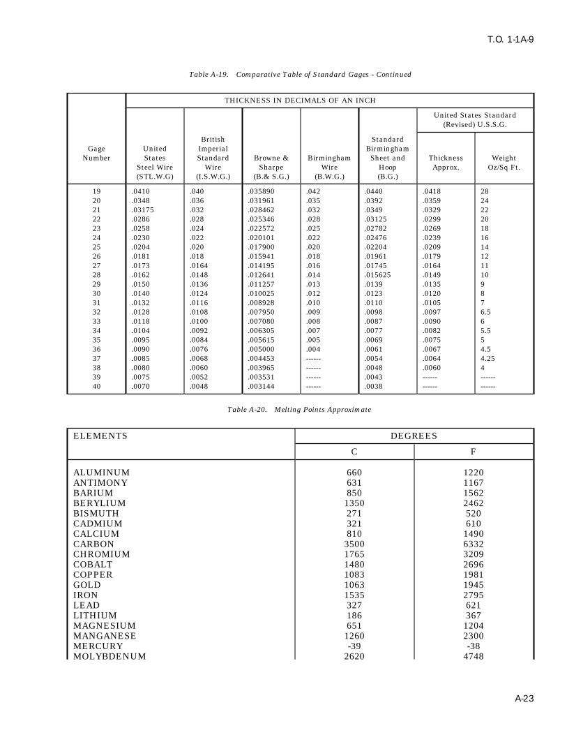
T.O. 1-1A-9
Table A-19. Comparative Table of Standard Gages - Continued
THICKNESS IN DECIMALS OF AN INCH
United States Standard(Revised) U.S.S.G.
British StandardGage United Imperial Birmingham
Number States Standard Browne & Birmingham Sheet and Thickness WeightSteel Wire Wire Sharpe Wire Hoop Approx. Oz/Sq Ft.(STL.W.G) (I.S.W.G.) (B.& S.G.) (B.W.G.) (B.G.)
19 .0410 .040 .035890 .042 .0440 .0418 2820 .0348 .036 .031961 .035 .0392 .0359 2421 .03175 .032 .028462 .032 .0349 .0329 2222 .0286 .028 .025346 .028 .03125 .0299 2023 .0258 .024 .022572 .025 .02782 .0269 1824 .0230 .022 .020101 .022 .02476 .0239 1625 .0204 .020 .017900 .020 .02204 .0209 1426 .0181 .018 .015941 .018 .01961 .0179 1227 .0173 .0164 .014195 .016 .01745 .0164 1128 .0162 .0148 .012641 .014 .015625 .0149 1029 .0150 .0136 .011257 .013 .0139 .0135 930 .0140 .0124 .010025 .012 .0123 .0120 831 .0132 .0116 .008928 .010 .0110 .0105 732 .0128 .0108 .007950 .009 .0098 .0097 6.533 .0118 .0100 .007080 .008 .0087 .0090 634 .0104 .0092 .006305 .007 .0077 .0082 5.535 .0095 .0084 .005615 .005 .0069 .0075 536 .0090 .0076 .005000 .004 .0061 .0067 4.537 .0085 .0068 .004453 ------ .0054 .0064 4.2538 .0080 .0060 .003965 ------ .0048 .0060 439 .0075 .0052 .003531 ------ .0043 ------ ------40 .0070 .0048 .003144 ------ .0038 ------ ------
Table A-20. Melting Points Approximate
ELEMENTS DEGREES
C F
ALUMINUM 660 1220ANTIMONY 631 1167BARIUM 850 1562BERYLIUM 1350 2462BISMUTH 271 520CADMIUM 321 610CALCIUM 810 1490CARBON 3500 6332CHROMIUM 1765 3209COBALT 1480 2696COPPER 1083 1981GOLD 1063 1945IRON 1535 2795LEAD 327 621LITHIUM 186 367MAGNESIUM 651 1204MANGANESE 1260 2300MERCURY -39 -38MOLYBDENUM 2620 4748
A-23

T.O. 1-1A-9
Table A-20. Melting Points Approximate - Continued
ELEMENTS DEGREES
C F
NICKEL 1446 2635PHOSPHOROUS (YELLOW) 44 111PLATINUM 1773 3223SILICON 1420 2588SILVER 961 1761TIN 232 449TUNGSTEN 3400 6152VANADIUM 1710 3110ZINC 420 787
A-24
T.O. 1-1A-9
GLOSSARY
A
ACID BRITTLENESS--Brittleness of steel resulting from use of acid solutions to remove scale, clean andelectroplate. Brittleness is caused by the absorption of hydrogen into the metal from the acid solu-tions (also called hydrogen embrittlement).
AGING--(a) Generally any change in properties with time which occurs at relatively low temperature(room or elevated) after a f inal heat treatment of a cold marking operation. Aging is a process inwhich the trend is toward restoration of real equilibrium and away from an unstable conditioninduced by a prior operation. (b) Specifically the formation of a new phase by cooling a solid solutionto super saturated state and allowing the super saturated solution to partially return to equilibriumby the formation of a less concentrated solid solution and a new phase.
AIR HARDENING--An alloy which does not require quenching from a high temperature to harden. Hard-ening of the material occurs simply by cooling in air from above critical temperature. The term refersonly to the ability of the material to harden in air and does not imply any definite analysis orcomposition.
AIR COOLING/QUENCHING--Cooling from an elevated temperature in air, still or forced.
ALLOY--A mixture with metallic properties composed of two or more elements of which at least one is ametal. However, a metal is not designated an ‘‘alloy’’ based on elements incidental to its manufac-ture. For example; iron, carbon, manganese, silicon, phosphorus, sulphur, oxygen, nitrogen and hydro-gen are incidental to the manufacture of plain carbon steel. It does not become an ‘‘alloy steel’’ untilthe elements are increased beyond regular composition or until other elements (metal) are added insignificant amounts for a specific purpose.
ALLOY ELEMENTS--Chemical elements comprising an alloy, usually limited to the metallic elementsadded to modify the basic metal properties.
AMORPHOUS--Non-crystalline.
ANNEALING--Generally it is a controlled heating procedure which leads to maximum softness, ductilityand formability. The annealing procedure is utilized for the following: (a) Remove stresses. (b) Inducesoftness. (c) After ductility, toughness, electrical, magnetic, or physical properties. (d) Refine crystal-line structure. (e) Remove gases. (f) Produce a definite micro-structure.
ANNEALING FULL--A controlled heating procedure which leads to maximum softness, ductility andformability.
ANNEALING, ISOTHERMAL--Heating of a ferritic steel to a austenitic structure (fully or partial) followedby cooling to and holding at a temperature that causes transformation of the austenite to a relativelysoft ferrite and carbide structure.
ANODIC OXIDE COATING--A thin film of aluminum oxide formed on the surface of aluminum andaluminum alloy parts by electro-chemical means.
AS CAST--Condition of a casting as it leaves the mold with no heat treatment.
AUSTENITE--A solid solution of iron carbide in gamma iron. It forms when the metal solidifies andremains a solution until it cools to about 732oC (1350oF). Theoretically the solution would remain ifthe iron or steel were cooled instantaneously from a bright red heat to atmospheric temperature, butin practice, this degree of rapidity is impracticable, and only a portion of the austenite is preserved byrapid cooling. Addition of certain alloying elements such as nickel and manganese perserves austenitebelow - 17oC (0oF).
Glossary 1

T.O. 1-1A-9
GLOSSARY - Continued
B
BARK--The decarburized skin or layer just beneath the scale found after heating steel in an oxidizingatmosphere.
BASE METAL--The metal to which other elements are added to form an alloy possessing specificproperties.
BESSEMER PROCESS--A process for making steel by blowing air through molten pig iron contained in asuitable vessel. The process is one of rapid oxidation primarily of silicon and carbon.
BILLET--An ingot or bloom that has been reduced through rolling or hammering to an approximate squareranging from 1 1/2 inches square to 6 inches square, or to an approximate rectangular cross-section ofequivalent area. Billets are classified as semi-finished products for re-rolling or forging.
BINARY ALLOY--An alloy containing two elements, apart from minor impurities.
BLACK ANNEALING--A process of box annealing of sheets prior to tinning whereby a black color isimparted to the surface of the product.
BLUE ANNEALING--A process of annealing sheets after rolling. The sheets, if fairly heavy, are allowedto cool slowly after the hot rolling; if of lighter gage, as is usually the case, they are passed singlythrough an open furnace for heating to the proper annealing temperature. The sheets have a bluish-black appearance.
BLUE BRITTLENESS--Brittleness occurring in steel when in the temperature range of 149o to 371oC(300o to 700oF), or when cold after being worked within this temperature range.
BOX ANNEALING--Softening steel by heating it, usually at a sub-critical temperature, in a suitable closedmetal box or pot to protect it from oxidation, employing a slow heating and cooling cycle; also calledclosed annealing or pot annealing.
BRIGHT ANNEALING--A process of annealing, usually with reducing gases, such that surface oxidation isreduced to a minimum, thereby yielding a relatively bright surface.
BRITTLENESS--Brittleness is the property of a material which permits little bending or deformationwithout fracture. Brittleness and hardness are closely associated.
BURNING--The heating of a metal to temperatures sufficiently close to the melting point to cause perma-nent injury. Such injury may be caused by the melting of the more fusible constituents, by thepenetration of gases such as oxygen into the metal with consequent reactions, or perhaps by thesegregation of elements already present in the metal.
BUTT-WELD--The welding of two abutting edges.
C
CARBON FREE--Metals and alloys which are practically free from carbon.
CARBURIZING (CEMENTATION)--Adding carbon to the surface of iron-base alloys by heating the metalbelow its melting point in contact with carbonaceous solids, liquids, or gases.
CASE--The surface layer of an iron-base alloy which has been made substantially harder than the interiorby the process of case hardening.
CASE HARDENING--A heat treatment of a combination of heat treatments in which the surface layer ofan iron-base alloy is made substantially harder than the interior by altering its composition bycarburizing, cyaniding, or nitriding.
Glossary 2

T.O. 1-1A-9
GLOSSARY - Continued
C (Cont)
CHAPMANIZING--A process for hardening steel by bubbling ammonia through a cyaniding salt bath andholding the finished part in the gas stream. This method produces a case almost as hard as nitridingat a time factor of slightly longer than required for cyaniding.
CHARPY IMPACT--An impact test made by measuring in a Charpy machine the energy required tofracture a standard notched specimen in bending. The values so obtained are merely comparativebetween different materials tested by the same method.
COLD DRAWING--The permanent deformation of metal below its recrystallization temperature, by draw-ing the bay through one or more dies.
COLD ROLLING--The permanent deformation of metal below its recrystallization temperature by rolling.This process is frequently applied in finishing rounds, sheets, strip, and tin plate.
COLD TREATING--Cooling to sub-zero temperature for various purposes, but primarily to promote trans-formation of austenite.
COLD WORKING--Plastic deformation of a metal at a temperature low enough to insure strain hardening.
CORE--The interior portion of an iron-base alloy which is substantially softer than the surface layer as theresult of case hardening. Also, that portion of a forging removed by trepanning; the inner part of arolled section of rimmed steel as distinct from the rimmed portion or rim; a body of sand or othermaterial placed in a mold to produce a cavity in a casting.
CONVERSION COATING (CHEMICAL)--A film intentionally produced on a metal by subjection to aselected chemical solution for the purpose of providing improved corrosion resistance or to improvethe adhesion of subsequently applied organic coating.
CYANIDING--Surface hardening by carbon and nitrogen absorption of an iron-base alloy article or portionof it by heating at a suitable temperature in contact with a cyanide salt, followed by quenching.
COOLING--Any decrease in temperature; however, specific term usually applies to reducing metal temper-ature in a gaseous environment rather than quenching in a liquid.
D
DECALESCENCE--When a piece of steel is heated, the temperature rises uniformly until it reaches apoint between 718oC and 732oC (1,325oF and 1,350oF). At this point the rise in temperature suddenlyhalts due to the fact that the metal absorbs the heat necessary for the change of state. After thishalt the temperature will continue its normal rate of increase. It is the halting in the temperaturerange that is termed decalescence. At the point of decalesence, the carbon and iron are forming asolid solution and the steel is passing from its annealed condition into its hardened condition.
DECARBURIZATION--The removal of carbon (usually refers to the surface of solid steel) by the (normallyoxidizing) action of media which reacts with carbon. The decarburized area is sometimes referred toas the bark.
Glossary 3

T.O. 1-1A-9
GLOSSARY - Continued
D (Cont)
DEFECTS IN METALS--Damage occurring to metal during manufacture/fabrication process. Some typicaldefects are as follows: (a) Blister - a defect in metal produced by gas bubbles either on the surface orformed beneath the surface. Very fine blisters are called pinhead or pepper blisters. (b) Blow hole - ahole produced during the solidification of metal by evolved gas which in falling to escape, is held inpockets. (c) Bursts -ruptures made in forging or rolling. (d) Fin (Flash) - a thin fin of metal formed atthe side of a forging or weld where a small portion of the metal is forced out between the edges of theforging or welding case. (e) Flake -Internal f issures (cracks or clefts) in large steel forgings or large(MASS) rolled shapes. In a factured surface or test piece, they appear as sizable areas of silverybrightness and coarser grain size than their surroundings. Sometimes known as ‘‘chrome checks’’ and‘‘hairline cracks.’’ (f) Ghost - (Ferrite ghost) a faint band of ferrite. (g) Lap - a surface defect appearingas a seam caused from folding over hot metal, f ins, or sharp corners and then rolling or forging, butnot welding, them into the surface. (h) Pipe - a cavity formed in metal (especially ingots) duringsolidification of the last portion of liquid metal causes the cavity or pipe. (i) Scab - a rough projectionon a casting caused by the mold breaking or being washed by the molten metal; or occuring where theskin from a blowhole has partly burned away and is not welded. (j) Seam - a crack on the surface ofmetal which has been closed but not welded; usually produced by blowholes which have becomeoxidized. If very fine, a seam may be called a hair crack or hair seam. (k) Segregation a mixture ofcompounds and elements, which, when cooled from the molten state, solidify at different tempera-tures. (l) Ductility the ability of a metal to withstand plastic deformation without rupture. Ductilityis usually determined by tension test using a standard test (2″ gauge length) specimen. The testspecimen is loaded in tension to rupture. The specimen is then assembled and measured for lengthand diameter at the fracture. The increase in length is expressed as per cent elongation and thedecrease in diameter as per cent reduction of area. The above terms measure ductility and since theyare comparative, considerable experience is required for proper evaluation of material for the purposeintended.
DUCTILITY--The property that permits permanent deformation before fracture by stress in tension.
E
ELASTIC LIMIT--The elastic limit of a material is the greatest load per unit area which will not produce ameasurable permanent deformation after complete release of load.
ELONGATION--The amount of permanent extension at any stage in any process which continuouslyelongates a body.
EMBRITTLEMENT--Loss of ductility of a metal, which may result in premature failure. (see acidbrittleness).
ENDURANCE LIMIT--The highest unit stress at which a material can be subjected to a very large numberof repetitions of loading and still show no evidence of failure. Above this limit failure occurs by thegeneration and growth of cracks until fracture results in the remaining section.
ENDURANCE RATIO--The ratio of the endurance limit for cycles of reversed f lexural stress to the tensilestrength.
EQUALIZING--Intermediate heat treatment (special) which assists in developing desired properties, pri-mary use is for equalizing/relieving stresses resulting from cold working.
EUTECTIC ALLOY--An alloy which has a lower melting point than neighboring compositions. More thenone eutectic composition may occur in a given alloy system.
EXFOLIATION--The cracking or f laking off of the outer layer of an object.
EXPOSURE--Heating to or subjecting to an elevating temperature or environment for a certain period oftime.
Glossary 4

T.O. 1-1A-9
GLOSSARY - Continued
E (Cont)
ETCHING--Attack of metals structure by reagents. In metallography, the process of revealing structualdetails by the preferential attack of reagents on a metal surface. (a) Micro - etching is for theexamination of the sample under a microscope and for this purpose the sample must be very carefullypolished (by an experienced person) prior to etching. (b) Macro-etching is for the examination of thesample under a low power magnifying glass or by unaided eye. High polishing for this purpose is notabsolutely essential; however, a good polish is necessary. (c) Deep-etching is a form of macro-etchingin which the sample with regular cut surface may be immersed in hot hydrocloric acid (50% acqueoussolution) and then examined for major defects such as inclusions, segregations, cracks; etc.
F
FATIGUE--The phenomenon of the progressive fracture of a metal by means of a crack which spreadsunder repeated cycles of stress.
FATIGUE LIMIT--Usually used as synonymous with endurance limit.
FERRITE--A solution in which alpha iron is the solvent, and which is characterized by a body centeredcubic crystal structure.
FILLET--A concave junction of two surfaces usually perpendicular.
FLAME HARDENING--A process of hardening a ferrous alloy by heating it above the transformationrange by means of a high-temperature f lame and then cooling as required.
FORGING STRAINS--Elastic strains resulting from forging or from cooling from the temperature.
FORMING--To shape or fashion with hand/tools or by a shape or mold.
FRACTURE TESTING--A test used to determine type of structure, carbon content and the presence ofinternal defects. The test specimen is broken by any method that will produce a clean sharp fracture.The fracture is then examined by eye or with the aid of a low former magnifying glass. A trained/experienced observer will determine grain size; approximate depth of carburized or decarburizedsurface area; the presence of inclusions of dirty steel; and defects such as seams, cracks, pipes burstsand f lakes.
FULLY HARDENED--Applies generally to the maximum hardness obtainable. (In particular, applies tomaterials that are hardened by a strain and/or age hardening process).
FUSIBLE ALLOYS--A group of nonferrous alloys which melt at relatively low temperatures. They usuallyconsist of bismuth, lead, tin, etc., in various proportions, and iron only as an impurity.
G
GALVANIC SERIES--A list of metals and alloys arranged in order of their relative potentials in a givenenvironment. The galvanic series indicates the tendency of the serval metals and alloys to set upgalvanic corrosion. The relative position within a group sometimes changes with external conditions,but it is only rarely that changes occur from group to group.
GRAINS--Individual crystals in metal. When metal is in molten state, the atoms have no uniform group-ing. However, upon solidification they arrange themselves in a geometric pattern.
GRAIN GROWTH--An increase in the grain size of metal.
Glossary 5

T.O. 1-1A-9
GLOSSARY - Continued
H
HARDENABILITY--The ability of an alloy to harden fully throughout the entire section thickness either bycold working or heat treatment. The maximum thickness at which this may be accomplished can beused as a measure of hardenability.
HARDENING--Hardening accomplished by heating the metal to a specified temperature, then rapidlycooling by quenching in oil, water, or brine. This treatment produces a fine grain structure, extremehardness, maximum tensile strength, and minimum ductility.
HARDNESS--Hardness refers to the ability of a material to resist abrasion, penetration, indentation, orcutting action. The wearing qualities of a material are in part dependent upon its hardness. Hard-ness and strength are properties which are closely related for wrought alloys.
HARDNESS TESTING--Test used to determine the ability of a metal to resist penetration. The testresults are usually directly related to tensile and yield strength of the metal involved. An exceptionwould be case hardness. See Section VIII for typical testing methods.
HEAT TINTING--Heating a specimen with a suitable surface in air for the purpose of developing thestructure by oxidizing or otherwise affecting the different constituents.
HEAT TREATMENT--An operation, or combination of operations, involving the heating and cooling of ametal or alloy in the solid state for the purpose of obtaining certain desirable conditions or properties.Heating and cooling for the sole purpose of mechanical working are excluded from the meaning of thisdefinition.
HOMOGENIZING--Annealing or soaking at very high temperatures in order to reduce alloy segregation bydiffusion.
HOT SHORTNESS--Brittleness in metal when hot. In iron when sulphur is in excess of the manganesenecessary to combine with it to form manganese sulphide the excess sulphur combines with the ironto form iron sulphide. This constituent has a lower melting point than the iron and the result can bethat steel may crack during hot working.
HYDROGEN EMBRITTLEMENT--See Acid Brittleness.
I
IMPACT TEST--A test in which one or more blows are suddenly applied to a specimen. The results areusually expressed in terms of energy absorbed or number of blows (of a given intensity) required tobreak the specimen. See Charpy Impact and Izod Impact.
INCLUSION--Particles of impurities, usually oxides, sulphides, silicates, and such which are mechanicallyheld during solidification or which are formed by subsequent reaction of the solid metal.
INDUCTION HARDENING--A process of hardening a ferrous alloy by heating above the transformationrange by means of electrical induction and then cooling as required.
M
MACHINABILITY--The cutting characteristic of metal and resulting surface finish using standard cuttingtools and coolant/lubricants. There are various factors that effect the machinability of a metal suchas hardness, grain size, alloy constituents, structure, inclusions; shape, type, condition of tool andcoolant. The standard machinability ratings are usually based on comparison to SAE 1112/Aisi B1112 Bessemer screw stock which is rated at 100% machinability.
Glossary 6

T.O. 1-1A-9
GLOSSARY - Continued
M (Cont)
MAGNA FLUX TESTING--A method of inspection used to detect/locate defects such as cavities, cracks orseams in steel parts at or very close to the surface. The test is accomplished by magnetizing the partwith equipment specially designed for the purpose and applying magnetic powder, wet or dry, Flawsare then indicated by the powder clinging to them (see Section VIII for additional data).
MALLEABILITY--Malleability is the property of a material which enables it to be hammered, rolled, or tobe pressed into various shapes without fracture. Malleability refers to compression deformation ascontrasted with ductility where the deformation is tensile.
MARTEMPERING--This is a method of hardening steel by quenching from the austenitizing temperatureinto a medium at a temperature in the upper part of or slightly above the martensite range andholding it in the medium until temperature is substantially uniform throughout the alloy is thenallowed to cool in air through the martensite range.
MARTENSITE--It is the decomposition product which results from very rapid cooling of austenite. Thelower the carbon content of the steel, the faster it must be cooled to obtain martensite.
MECHANICAL HARDNESS--See Hardness.
MECHANICAL PROPERTIES--Those properties that reveal the reaction, elastic and inelastic, of a mate-rial to an applied force, or that involve the relationship between stress and strain; for example,tensile strength, yield strength, and fatigue limit.
MECHANICAL TESTING--Testing methods by which mechanical properties are determined.
MECHANICAL WORKING--Subjecting metal to pressure exerted by rolls, presses, or hammers, to changeits form, or to affect the structure and therefore the mechanical and physical properties.
MODULUS OF ELASTICITY--The ratio, within the limit of elasticity, of the stress in the correspondingstrain. The stress in pounds per square inch is divided by the elongation in fractions of an inch foreach inch of the original gage length of the specimen.
N
NITRIDING--Adding nitrogen to iron-base alloys by heating the metal in contact with ammonia gas orother suitable nitrogenous material. Nitriding is conducted at a temperature usually in the range502o-538oC (935o-1000oF) and produces surface hardening of the metal without quenching.
NORMALIZING--Heating iron-base alloys to approximately 55oC (100oF) above the critical temperaturerange, followed by cooling to below that range in still air at ordinary temperatures. This process isused to remove stresses caused by machining, forging, bending, and welding.
O
OVERHEATING--Heating to such high temperatures that the grains have become coarse, thus impairingthe properties of the metal.
P
PATENTING--Heating iron-base alloys above the critical temperature range followed by cooling below thatrange in air, or in molten lead, or a molten mixture of nitrate or nitrites maintained at a temperatureusually between 427o-566oC (800-1050oF),depending on the carbon content of the steel and theproperties required of the finished product. This treatment is applied to wire and to medium or highcarbon steel as a treatment to precede further wire drawing.
Glossary 7
T.O. 1-1A-9
GLOSSARY - Continued
P (Cont)
PHYSICAL PROPERTIES--Those properties exclusive of those described under mechanical properties; forexample, density, electrical conductivity, coefficient of thermal expansion. This term has often beenused to describe mechanical properties, but this usage is not recommended.
PHYSICAL TESTING--Testing methods by which physical properties are determined. This term is alsoinadvisedly used to mean the determination of the mechanical properties.
PICKLING--Removing scale from steel by immersion in a diluted acid bath.
PLASTIC DEFORMATION--The permanent change in size or shape of a material under stress.
POTENTIOMETER--Potentiometer 1s an instrument used to measure thermocouple voltage by balancing aknown battery voltage against it.
PROCESS ANNEALING--Heating iron-base alloys to a temperature below or close to the lower limit of thecritical temperature range, followed by coolings desired. This treatment is commonly applied to sheetand wire and the temperatures generally used are from 549o to 649oC (1020o to 1200oF).
PROOF STRESS--The proof stress of a material is that load per unit area which a material is capable ofwithstanding without resulting in a permanent deformation of more than a specified amount per unitof gage length after complete release of load.
PROPORTIONAL LIMIT--The proportional limit of a material is the load per unit area beyond which theincreases in strain cease to be directly proportional to the increases in atress.
PYROMETER--An instrument for measuring temperature.
Q
QUENCHING--Rapid cooling by immersion in liquids or gases.
QUENCHING MEDIA--Quenching media are liquids or gases in which metals are cooled by immersion.Some of the more common are brine (10 percent sodium chloride solution), water 18oC (65oF), f ish oil,paraffin base petroleum oil, machine oil, air, engine oil, and commercial quenching oil.
R
RECALESCENCE--When steel is slowly cooled from a point above the critical temperature, the coolingproceeds at a uniform rate until the piece reaches a point between 677o and 704oC (1,250o and1,300oF). At this time, the cooling is noticeably arrested and the metal actually rises in temperatureas the change of state again takes place. This change is the opposite of decalescence and is termedrecalescence.
REDUCTION OF AREA--The difference between the original cross-sectional area and that of the smallestarea at the point of rupture. It is usually stated as a percentage of the original area; also called‘‘contraction of area.’’
REFINING TEMPERATURE OR HEAT--A temperature employed in case hardening to refine the case andcore. The first quench is from a high temperature to refine the core and the second quench is from alower temperature to further refine and harden the case.
S
SCALE--A coating of metallic oxide that forms on heated metal.
SENSITIZING--Developing a condition in stainless steels, which is susceptible to intergranular corrosion.The condition is usually formed by heating the steel above 800oF and cooling slowly, e.g., welding.
Glossary 8

T.O. 1-1A-9
GLOSSARY - Continued
S (Cont)
SHEETS COLD ROLLED--The f lat products resulting from cold rolling of sheets previously produced byhot rolling.
SHEETS HOT ROLLED--The f lat-rolled products resulting from reducing sheet bars on a sheet mill, orslabs, blooms, and billets on a continuous strip-sheet mill.
SOAKING--Holding steel at an elevated temperature for the attainment of uniform temperature through-out the piece.
SOLIDIFICATION RANGE--The temperature range through which metal freezes or solidifies.
SPALLING--The cracking and f laking of small particles of metal from the surface.
SPHEROIDAL OR SPHEROIDIZED CEMETITE--The globular condition of iron carbide resulting from aspheroidizing treatment. The initial structure may be either pearlitic or martensitic.
SPHEROIDIZING--Any process of heating and cooling steel that produces a rounded or globular form ofcarbide. The spheroidizing methods generally used are: (a) Prolonged heating at a temperature justbelow the lower critical temperature, usually followed by relatively slow cooling. (b) In the case ofsmall objects of high carbon steels, the spheroidizing result is achieved more rapidly by prolongedheating to temperatures alternately within and slightly below the critical temperature range. (c) Toolsteel is generally spheroidized by heating to a temperature of 749o-804oC (1380o-1480oF) for carbonsteels and higher for many alloy tool steels, holding at heat from 1 to 4 hours, and cooling slowly inthe furnace.
STRAIN--The elongation per unit length.
STRESS--The internal load per unit area.
STRESS-RELIEF--This is annealing process which removes or reduces residual stresses retained afterforming, heat treating, welding or machining. The anneal is accomplished at rather low temperaturesfor the primary purposes of reducing residual stresses, without material affecting other properties.
T
TEMPERING (ALSO TERMED DRAWING)--Reheating hardened steel to some temperature below thelower critical temperature, followed by any desired rate of cooling. Although the terms ‘‘tempering’’and ‘‘drawing’’ are practically synonymous as used in commercial practice, the term ‘‘tempering’’ ispreferred.
TENSILE STRENGTH--The tensile strength is the maximum load per unit area which a material iscapable of withstanding before failure. It is computed from the maximum load carried during atension test and the original cross-sectional area of the specimen.
TENSION--That force tending to increase the dimension of a body in the direction of the force.
THERMOCOUPLE--Thermocouple consists of a pair of wires of dissimilar metals connected at both ends.When the two junctions are subjected to different temperatures an electric potential is set upbetween them. This voltage is almost in direct proportion to the temperature difference, and hence, avoltage measuring instrument inserted in the circuit will measure temperature. The voltage measur-ing instrument is usually calibrated in oC or oF.
TOLERANCES--Slight deviations in dimensions or weight or both, allowable in the various products.
V
VISCOSITY--Viscosity is the resistance offered by a f luid to relative motion of its parts.
Glossary 9

T.O. 1-1A-9
GLOSSARY - Continued
W
WIRE--The product obtained by drawing rods through a series of dies.
WORK HARDNESS--Hardness developed in metal resulting from mechanical working, particularly coldworking.
Y
YIELD POINT--The load per unit of original cross section at which a marked increase in deformationoccurs without increase in load.
YIELD STRENGTH--Stress arbitrarily defined as the stress at which the material has a specified perma-nent set (the value of 0.2% is widely accepted).
YOUNG’S MODULUS--See Modulus of Elasticity.
Glossary 10