navisp-el1-001 - complementary pnt infrastructure in leo
TRANSCRIPT
8 December 2020
NAVISP-EL1-001 - Complementary
PNT Infrastructure in LEO Final Presentation
Teleconference

Introduction
2 8 December 2020 NAVISP-EL1-001 - Complementary PNT Infrastructure in LEO – Final Presentation

Project Overview and Objectives
• The proposed approach was to perform an Enhanced Phase 0 Mission Analysis and Needs Identification Study for a potential
future system to provide signals from Low Earth Orbit that can be used to complement existing GNSS with an enhanced Position,
Navigation and Timing (PNT) service.
• Such a system would:
– Improve the robustness and resilience of existing GNSS.
– Introduce some additional capabilities such as improved in-building performance.
8 December 2020 NAVISP-EL1-001 - Complementary PNT Infrastructure in LEO – Final Presentation3

Task Overview
• The study was split into four sequential tasks:
• Task 1 - High Level Definition
– This task involved the high level definition of eight Design Concepts (DCs) based on the original system concepts and use cases
input to the study. These DCs underwent downselection to a subset of four for further study in Task 2. Task 1 was concluded in
the Preliminary Mission Definition Review (PMDR)
• Task 2 - System Analysis and Critical Trade-offs
– The output of the PMDR was consolidated. A trade-off definition and analysis was performed to downselect from the four DCs
selected in Task 1 to two DCs. The results were presented in at Key Point 2.
– The two downselected DCs were further elaborated. Task 2 was concluded in the System Concept Review (SCR)
• Task 3 - Consolidation of Architecture and Performance Analyses
– This task involved consolidation of the SCR conclusions into an Architectural Design Document (ADD). Task 3 was concluded in
the Mission Definition Review (MDR).
• Task 4 - Final Report
– Task 4 involves the final synthesis of the analyses for conclusion in the Final Report.
8 December 2020 NAVISP-EL1-001 - Complementary PNT Infrastructure in LEO – Final Presentation4

Task 1 - High Level Definition
5 8 December 2020 NAVISP-EL1-001 - Complementary PNT Infrastructure in LEO – Final Presentation

Methodology - Development from KP1
• At KP1 a matrix-style method was proposed for assessing all original four design concepts against the KPIs and FoMs.
• Discussion at the KP1 workshop and further work showed this approach was not optimal.
• The KPIs and original six Use Cases were used to develop a set of Mission Objectives, which in turn implied potential Features for
the LEO system.
• KPIs without a mapping to a Mission Objective were retained.
• The Features were then used to define an expanded set of eight system design concepts, to allow full exploration of the solution
space.
6 8 December 2020 NAVISP-EL1-001 - Complementary PNT Infrastructure in LEO – Final Presentation
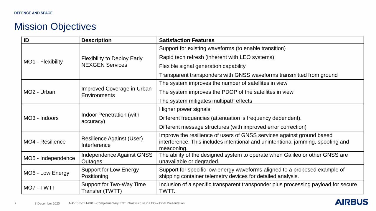
Mission Objectives
7
ID Description Satisfaction Features
MO1 - FlexibilityFlexibility to Deploy Early
NEXGEN Services
Support for existing waveforms (to enable transition)
Rapid tech refresh (inherent with LEO systems)
Flexible signal generation capability
Transparent transponders with GNSS waveforms transmitted from ground
MO2 - UrbanImproved Coverage in Urban
Environments
The system improves the number of satellites in view
The system improves the PDOP of the satellites in view
The system mitigates multipath effects
MO3 - IndoorsIndoor Penetration (with
accuracy)
Higher power signals
Different frequencies (attenuation is frequency dependent).
Different message structures (with improved error correction)
MO4 - ResilienceResilience Against (User)
Interference
Improve the resilience of users of GNSS services against ground based
interference. This includes intentional and unintentional jamming, spoofing and
meaconing.
MO5 - IndependenceIndependence Against GNSS
Outages
The ability of the designed system to operate when Galileo or other GNSS are
unavailable or degraded.
MO6 - Low EnergySupport for Low Energy
Positioning
Support for specific low-energy waveforms aligned to a proposed example of
shipping container telemetry devices for detailed analysis.
MO7 - TWTTSupport for Two-Way Time
Transfer (TWTT)
Inclusion of a specific transparent transponder plus processing payload for secure
TWTT.
8 December 2020 NAVISP-EL1-001 - Complementary PNT Infrastructure in LEO – Final Presentation
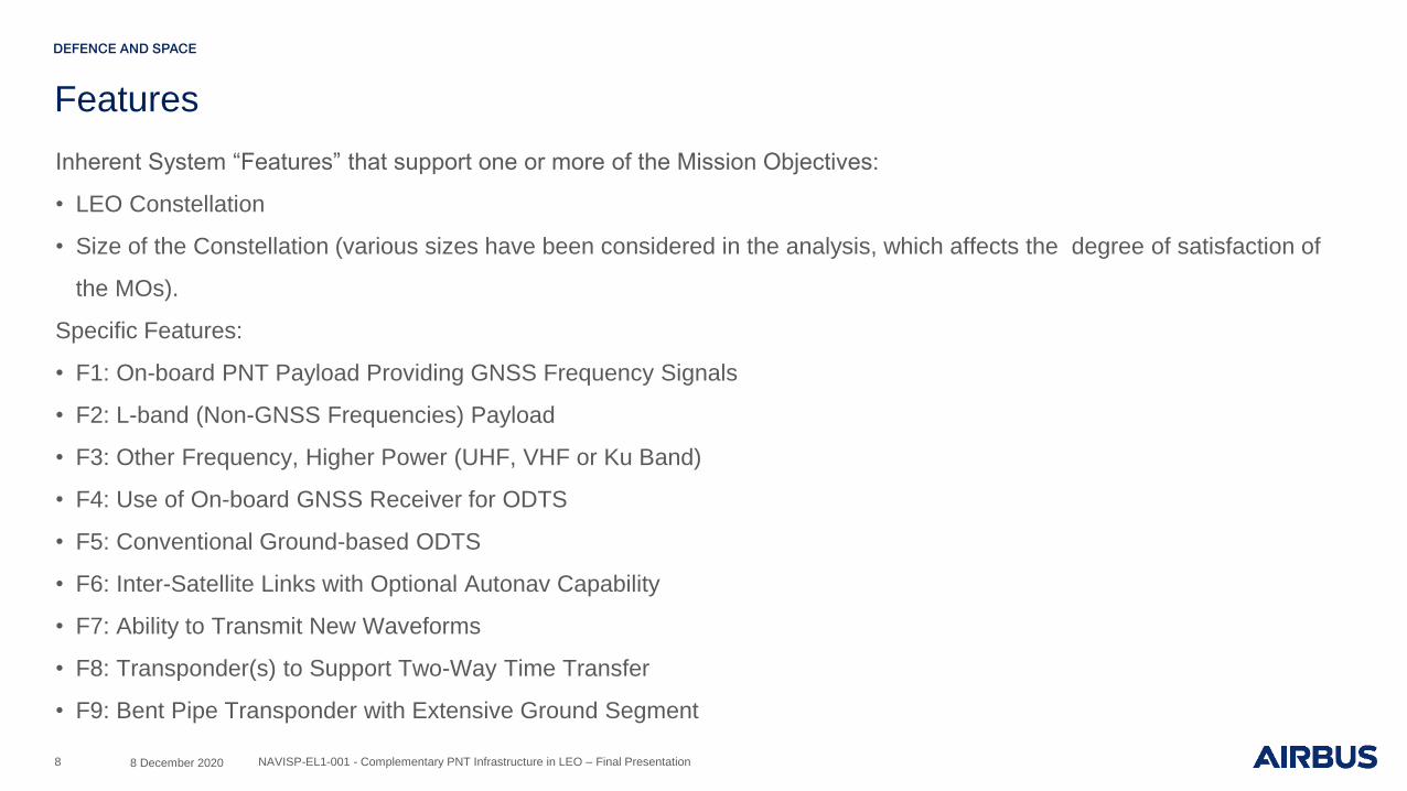
Features
Inherent System “Features” that support one or more of the Mission Objectives:
• LEO Constellation
• Size of the Constellation (various sizes have been considered in the analysis, which affects the degree of satisfaction of
the MOs).
Specific Features:
• F1: On-board PNT Payload Providing GNSS Frequency Signals
• F2: L-band (Non-GNSS Frequencies) Payload
• F3: Other Frequency, Higher Power (UHF, VHF or Ku Band)
• F4: Use of On-board GNSS Receiver for ODTS
• F5: Conventional Ground-based ODTS
• F6: Inter-Satellite Links with Optional Autonav Capability
• F7: Ability to Transmit New Waveforms
• F8: Transponder(s) to Support Two-Way Time Transfer
• F9: Bent Pipe Transponder with Extensive Ground Segment
8 8 December 2020 NAVISP-EL1-001 - Complementary PNT Infrastructure in LEO – Final Presentation

System Design Concepts
• DC#1: Large, Full-featured Independent System
• DC#2: Highly Compliant Complementary System, with Two-Way Communications Transponder
• DC#3: Largely Compliant Dedicated System, without Transponder
• DC#4: Extended L-Band, Dedicated System
• DC#5: GNSS Payload Hosted on Communications Constellation
• DC#6: Dedicated System, Bent Pipe Transponder, ToA PNT Service
• DC#7: Hosted System, Doppler Ranging
• DC#8: Doppler based PNT from Commercial Communications Constellation
9 8 December 2020 NAVISP-EL1-001 - Complementary PNT Infrastructure in LEO – Final Presentation

System Trade Space
10
MO# Description Implied Feature/s 1 2 3 4 5 6 7 8
MO1Flexibility to deploy early NEXGEN
servicesGNSS frequency; Transponder Y Y Y Y Y P P P
MO2Improved coverage in urban
environmentsGNSS frequency, enhanced multipath mitigation Y Y Y Y Y Y Y P
MO3 Indoor penetration (with accuracy) Other frequency, higher power (e.g. L/MSS, Ku, UHF) Y Y Y Y N Y Y Y
MO4 Resilience against (user) interference Other frequency, higher power Y Y Y Y N Y Y Y
MO5 Independence against GNSS outages No use of GNSS Y N N N N P P P
MO6 Support for low energy positioningWaveform/nav message (cannot be deployed by current
MEO)Y Y Y N N Y Y Y
MO7 TWTT Transponder Y Y N N N P P P
8 December 2020 NAVISP-EL1-001 - Complementary PNT Infrastructure in LEO – Final Presentation
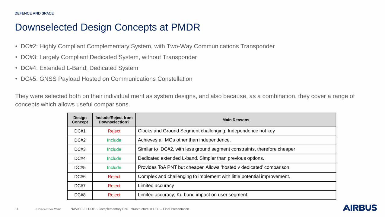
Downselected Design Concepts at PMDR
• DC#2: Highly Compliant Complementary System, with Two-Way Communications Transponder
• DC#3: Largely Compliant Dedicated System, without Transponder
• DC#4: Extended L-Band, Dedicated System
• DC#5: GNSS Payload Hosted on Communications Constellation
They were selected both on their individual merit as system designs, and also because, as a combination, they cover a range of
concepts which allows useful comparisons.
11
Design Concept
Include/Reject from Downselection?
Main Reasons
DC#1 Reject Clocks and Ground Segment challenging; Independence not key
DC#2 Include Achieves all MOs other than independence.
DC#3 Include Similar to DC#2, with less ground segment constraints, therefore cheaper
DC#4 Include Dedicated extended L-band. Simpler than previous options.
DC#5 Include Provides ToA PNT but cheaper. Allows ‘hosted v dedicated’ comparison.
DC#6 Reject Complex and challenging to implement with little potential improvement.
DC#7 Reject Limited accuracy
DC#8 Reject Limited accuracy; Ku band impact on user segment.
8 December 2020 NAVISP-EL1-001 - Complementary PNT Infrastructure in LEO – Final Presentation
Task 2 - System Analysis and Critical Trade-offs
12 8 December 2020 NAVISP-EL1-001 - Complementary PNT Infrastructure in LEO – Final Presentation

Use Cases (1-3)
• UC1: Maximum Signal Penetration FOM
– A mass market user who needs a system optimised for signal penetration through a signal attenuating environment (e.g. an
airport terminal), with metre-level accuracy requirements.
• UC2: Low Energy Positioning FOM
– ‘Install-and-forget’ tracking device for:
– smart water and gas meters
– shipping containers
– pipe monitoring.
– Case a) has the receiver performing very infrequent cold-starts
– Case b) has the receiver performing semi-frequent warm-starts
• UC3: TWTT FOM
– A user who needs more accurate synchronisation with UTC than can be provided by a clock-augmented MEO GNSS receiver,
with security/integrity.
– The accuracy target was modified at PMDR:
– 1ns target was retained (high accuracy – low scalability, scientific users)
– 100ns, 1ms, 1s is also to be considered (authentication capability rather than accuracy is the driver at 1s).
8 December 2020 NAVISP-EL1-001 - Complementary PNT Infrastructure in LEO – Final Presentation13

Use Cases (4-6)
• UC4a: Arctic Augmentation
– The Galileo performance for accuracy is adequate at high latitudes and integrity is outside the scope of the requirement.
Consequently this UC (specific scenario of the original UC4) was dropped at PMDR.
• UC5: Increased Resilience and Robustness FOM
– A First Responder who needs a system optimised for resilience and robustness, in a noisy RF environment.
– The link budget identifying the tolerance of interference (J/S levels) is a critical FOM. Indoor penetration capable of supporting
a full cold start acquisition and transition to tracking cycle (UC1 is tracking only) is required.
– DC5 cannot compete for this UC as it has no high power signal.
• UC6: Connected Autonomous Vehicles FOM
– A Multi-GNSS/LEO receiver supporting near-real-time calibration of the other sensors (camera, radar, lidar) used by a future
Connected Autonomous Road Vehicle. The vehicle’s position will be provided by Precise Point Positioning.
– Case a) is in an urban environment and will be the focus of study
– Case b) is on a motorway with infrequent interference across L-band frequencies and will act as a baseline.
– The feedback from PMDR was to focus on UC6a with UC6b used as benchmark and to use this system to stabilise PPP based
on an assessment of signal power levels and the number of satellites required.
8 December 2020 NAVISP-EL1-001 - Complementary PNT Infrastructure in LEO – Final Presentation14
FOM Criticality Assessment
15
• Link Budget
– Link budget is a critical parameter for all DCs as the missions are either small satellites (due to cost limitations) or hosted
payloads (with limited SWAP). The ability to close links using payloads that can be implemented and to deliver sufficient
S/N to the user to provide system performance are critical.
• Accuracy
– Accuracy is critical for UC1, UC5 and UC6. UC1 and UC5 are in-building; accuracies outside building (or room) limits are
not useful. Vertical accuracy and VDOP also need consideration. UC6b is CAV with a moderate accuracy requirement.
UC3 has timing accuracy requirements which are specific to the UC but not related to the navigation performance.
• Availability
– The availability requirement is very high for UC6. UC1 has low quality (mobile phone) INS and hence these degrade
rapidly compared to UC5. UC2 and UC3 have lower availability requirements
• Continuity
– The continuity requirements for UC5 and UC6 are very high. They are moderate for UC1 and lower for UC2 and UC3.
This will drive the constellation sizing (minimise gaps or reductions in coverage) as well as power requirements where
shadowing and attenuation are present (indoor and CAV UCs).
• Energy per Fix
– This applies to the low energy UC2 only.
8 December 2020 NAVISP-EL1-001 - Complementary PNT Infrastructure in LEO – Final Presentation

FOM Criticality Summary
16
• The criticality of the FOM is presented below as a RAG table with the following criteria:
– Red Not useful for downselection
– Amber Used in simplified form for downselection
– Green Used directly for downselection
• The trade-off considers the design concept satisfaction of the use cases by initial FOM analysis in order to make the
downselection. This utilises the criticality identified above.
• For the KP2 downselection, the link budget activity focused on the TWSTFT capability as it is a key differentiator between
DC2 and DC3.
8 December 2020 NAVISP-EL1-001 - Complementary PNT Infrastructure in LEO – Final Presentation

DC2 Analysis
17
• Only the Ku-band case shows positive link margin for TWSTFT but this does not have the full range of weather losses
expected for an operational system, especially if it is to meet the 98% system availability target.
• The system is downlink SNR limited due to the very low input powers. The performance also worsens with increasing
frequency (covered by improved UE for the Ku case).
– Additional satellite amplification was analysed (this can be implemented due to the very low RF powers involved). An additional SSPA was
put in series with the existing unit, though this also came with additional noise and so the performance was not recovered.
• A further modification was made to the S-band system to see if positive margin could be regained using some quite
significant changes (though not all of these have a technical solution as yet):
– The UE power was increased from 5W to 10W (this would impact UE size, weight and power, and runtime)
– The satellite Rx antenna was changed to an active system of 10dBi based on an available terrestrial unit
– The satellite Tx antenna was changed to a 6dBi active system; no design exists for this at present and this would also introduce additional
noise which was not modelled.
– All these changes still only gave a slightly positive margin of ~+2dB. This is not considered acceptable at this phase of a project and also
does not resolve the lack of frequency availability at S-band due to the ITU limits.
• Analysis has demonstrated that the TWSTFT payload is not practical. Since DC3 replicates this DC in all but the TWSTFT payload,
DC2 is rejected.
8 December 2020 NAVISP-EL1-001 - Complementary PNT Infrastructure in LEO – Final Presentation
DC3 Analysis
18
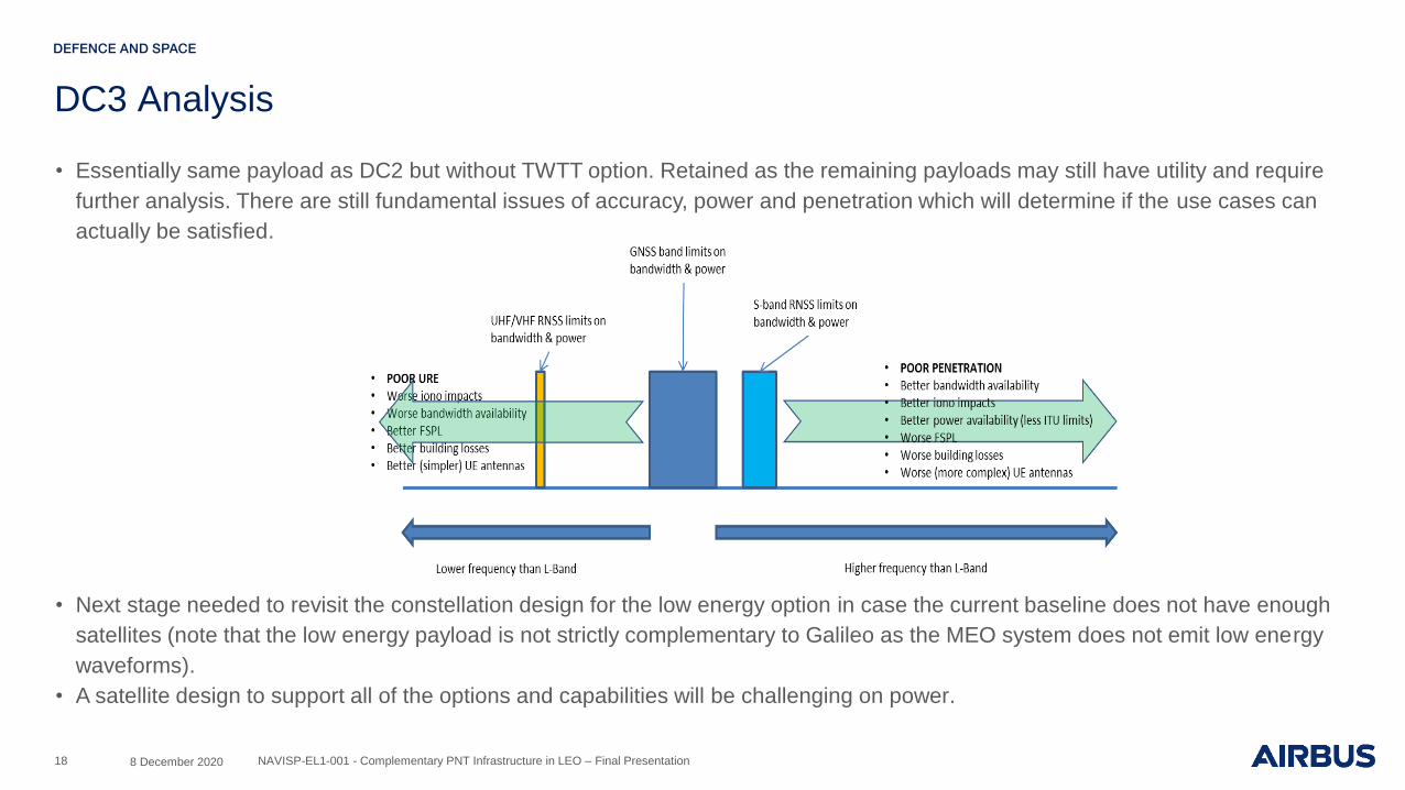
• Essentially same payload as DC2 but without TWTT option. Retained as the remaining payloads may still have utility and require
further analysis. There are still fundamental issues of accuracy, power and penetration which will determine if the use cases can
actually be satisfied.
• Next stage needed to revisit the constellation design for the low energy option in case the current baseline does not have enough
satellites (note that the low energy payload is not strictly complementary to Galileo as the MEO system does not emit low energy
waveforms).
• A satellite design to support all of the options and capabilities will be challenging on power.
8 December 2020 NAVISP-EL1-001 - Complementary PNT Infrastructure in LEO – Final Presentation
DC4 Analysis
19
• This DC adds the “extended frequency” S-band option to the basic L-band PNT payload. This is a relatively simple
architecture and may be acceptable on satellite power.
• As with DC3 the baseline constellation for this is also only 48 SV which is not enough for the S-band as it is unique (not
supported on MEO). Whether the full 224 satellite constellation is required depends on service mix supported via S-band
as it adds occasional “extra” signal which may also carry aiding data to the MEO system rather than offering a total
capability at S-band.
• The next stage needed to assess how to get extra data into the S-band payload efficiently and cheaply (i.e. not requiring
ISL or huge numbers of ground stations).
• This DC is retained.
8 December 2020 NAVISP-EL1-001 - Complementary PNT Infrastructure in LEO – Final Presentation
DC5 Analysis
20
• Delivers few other services to support UCs as this is naturally limited by the amount of resources available for hosted
payloads.
• Initial link budgets indicate quite high powers are required to deliver any kind of service due to the lack of directivity from
the payload antenna driven by the wide beamwidth to provide service down to 5 deg. elevation. Could be relaxed with
many more payloads but this would drive the system cost up and require access to hosting opportunities only on mega-
constellations.
– Means that hosting opportunities are very limited.
– There are also concerns about the availability of launch vehicles to launch and maintain the constellations, launch pads
and payload integration areas.
• The system is constrained by the business case of the hosting constellation.
– System could fail at a business level or the priorities of the system could change, either resulting in a reduction in hosting
capability, a change in orbit which is not compatible with the hosted payload or a change in launch schedule which
impacts replenishment and hence the availability and continuity of the hosted system.
• It is assumed that any complementary system would require continuous operation for 10-15 years. It is not clear that any
hosting-based system can guarantee this.
• It is concluded that a hosted payload is not a viable option for an operational complementary mission. It may still be
attractive for testing some concepts however.
8 December 2020 NAVISP-EL1-001 - Complementary PNT Infrastructure in LEO – Final Presentation

Downselected Design Concepts at KP2
• Based on the assessments, DC3 and DC4 were retained post KP2 for further elaboration.
– DC3: Largely Compliant Dedicated System, without Transponder
– DC4: Extended L-Band, Dedicated System
• They were selected both on their individual merit as system designs, and also because, as a combination, they cover a
range of concepts which allows useful comparisons.
• DC2 replicates DC3 except for the inclusion of the TWSTFT payload which is deemed impractical to implement on a small
satellite.
• DC5 is deemed to be impractical for an operational complementary mission due to the technical, launch and business
constraints of integrating to a hosting system.
21 8 December 2020 NAVISP-EL1-001 - Complementary PNT Infrastructure in LEO – Final Presentation

Overview of DC3
Use Case 2 Figures Of Merit (FOM)
• The primary difference between DC3 and DC4 is the inclusion of
the “low energy” waveforms to support IoT and similar receivers
• The waveforms assessed are those defined in the ITT
• The User Equipment (UE) and its interaction with the waveform is
key in delivering the Energy per Fix FOM
• The achieved performance is covered in the slides 39/40
• The Accuracy and Environment FOM are governed by a mix of
payload and waveform options
• The achieved performance is covered in the System section
22
Parameter Definition
UC 2a) 2b)
Name Low Energy Positioning
Description
‘Install-and-forget’ tracking device for: i) smart water and gas meters, ii) shipping containers and iii) pipe monitoring.
Case a) has the receiver performing very infrequent cold-starts Case b) has the receiver performing semi-frequent warm-starts
Led By NSL
Scenario Period 15 years
Start Condition Every start is a cold start from
hibernation. Wakeup is every 24 hours.
Every start is a warm start. Wakeup is every 15 minutes.
Latitude/Longitude Range
i) ii) iii)
Global or at least all populated land masses
Global or at least all major trade routes and
ports Global
Environment Primarily indoor, urban
environment
Open sky, primarily outdoor, including urban
environment or complete blocking for
entire journey
Open sky, primarily outdoor
Interference? Yes None None
User Utility companies
Shipping companies, businesses that require the shipping of goods,
logistics providers, insurance companies
Oil/Gas/Water companies
User Equipment
Smart meter, GNSS receiver,
communications hub and relevant
communications hardware, platform to
view data
Low cost receiver on container, m2m devices on board ship/at dock, platform to view data
Sensors, GNSS receiver, relevant communications
hardware, platform to view data
Multipath Environment Yes None None
Figure of Merit Targets
Accuracy 10m 30m 30m
Availability/Service Coverage
90-95%
Continuity 90%
Energy per Fix (Target in the order of) 10mJ
8 December 2020 NAVISP-EL1-001 - Complementary PNT Infrastructure in LEO – Final Presentation
DC3 (and DC4) System Summary
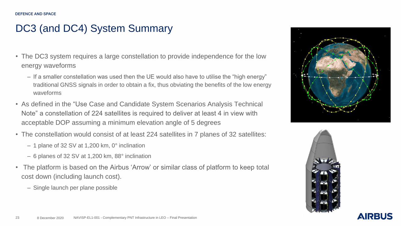
• The DC3 system requires a large constellation to provide independence for the low
energy waveforms
– If a smaller constellation was used then the UE would also have to utilise the “high energy”
traditional GNSS signals in order to obtain a fix, thus obviating the benefits of the low energy
waveforms
• As defined in the “Use Case and Candidate System Scenarios Analysis Technical
Note” a constellation of 224 satellites is required to deliver at least 4 in view with
acceptable DOP assuming a minimum elevation angle of 5 degrees
• The constellation would consist of at least 224 satellites in 7 planes of 32 satellites:
– 1 plane of 32 SV at 1,200 km, 0° inclination
– 6 planes of 32 SV at 1,200 km, 88° inclination
• The platform is based on the Airbus ‘Arrow’ or similar class of platform to keep total
cost down (including launch cost).
– Single launch per plane possible
23 8 December 2020 NAVISP-EL1-001 - Complementary PNT Infrastructure in LEO – Final Presentation

DC3 System Summary
• The DC3 system uses a network of ground stations to uplink navigation data as
normal for a GNSS system
– There is no transparent payload so continuous contact is not required
– ISL are not baselined to keep cost and mass down though Arrow could support these
• The ground system requires a self-monitoring capability
– Some of this could be provided by “trusted UE”
• Orbit determination (OD) is supported by the MEO GNSS system
– Either autonomous on-board or post-processed GNSS location data on-ground; OD
data is required on ground to enable uplink of constellation NAV message data
– Updated NAV message analysis in the System Concept Trade-Off Report
– Limited detailed information on interference in UHF and VHF bands but are
known to be congested and noisy, simple to create jammers
– Iono impacts mean that performance cannot meet the DC3 Accuracy FOM
– Dual band system barely meets minimum FOM requirement
– This is not the complete UERE; additional errors must be included
24
FREQUENCY CORRECTED IONO ERROR (m)
Single freq correction Dual band system
L-Band (1575 MHz) 2.4 0.4
UHF (400MHz) 38 6
VHF (150MHz) 269 45
8 December 2020 NAVISP-EL1-001 - Complementary PNT Infrastructure in LEO – Final Presentation

DC3 Conclusions
• L-band payload may self-interfere with the GNSS Rx required for payload functionality
– Link budget derives Tx EIRP, transmits directly in GNSS bands so no filtering
– Estimate of isolation from platform and from FBR of upgraded GNSS Rx antenna still has power much greater than
dynamic range of receiver
• The UHF/VHF payload cannot meet the Use Case FOM
– Iono impacts prevent accuracy achievement
– UE design barely meets the targeted energy-per-fix
• Frequency availability is a concern for UHF/VHF
• The remaining DC payload power is insufficient for the S-band system
– Provides no meaningful power margin over the extant L-band signal
25 8 December 2020 NAVISP-EL1-001 - Complementary PNT Infrastructure in LEO – Final Presentation

Overview of DC4
Use Case Figures Of Merit (FOM)
• The primary difference between DC3 and DC4 is the removal of
the low energy UHF/VHF waveform freeing up power for the S-
band payload
• The primary focus of this DC is the excess power of the S-band
system to provide penetration (Use Case 1) and the ability to
provide a communications channel to support the MEO
constellation and provide “other” added value data
• Such excess power can also support improved resilience which
supports Use Case 5
26
Parameter Definition
UC 1
Name Maximum Signal Penetration
Description A mass market User who needs a system optimised for signal penetration
through a signal attenuating environment (e.g. an airport terminal), with metre-level accuracy requirements.
Led By Airbus
Scenario Period 45 mins
Start Condition User has valid position fix from MEO GNSS
Latitude/Longitude Range 75°N-75°S latitude, all longitudes
Environment Inside large building. Masking angle v azimuth map can be used.
Interference? Attenuation from building (Penetration models required – inc. concrete, steel,
glass)
User Mass market, Civilian
User Equipment Mass market smartphone, multi-constellation dual frequency GNSS receiver,
typical sensors. App with dedicated processing functions
Multipath Environment Inside large building. User travelling at walking pace 5kmph aka. "Urban
Pedestrian".
Figure of Merit Targets
Accuracy Horizontal 2D 95% Confidence: 7m
Availability/Service Coverage
95%
Continuity Continuity Interval 60mins
Continuity 90%
Parameter Definition
UC 5
Name Increased Resilience and Robustness
Description A First Responder who needs a system optimised for resilience and
robustness, in a noisy RF environment.
Led By Airbus
Scenario Period 45 mins
Start Condition Cold start, indoor, MEO GNSS possibly compromised. LEO Complementary
GNSS almanac current and available.
Latitude/Longitude Range 75°N-75°S latitude, all longitudes
More constrained sub-cases could be considered.
Environment Mixed Indoor and Outdoor. Concrete, glass and steel multi-story buildings.
City model for outdoor signal blocking. Masking angle versus azimuth maps can be developed for use in simulations.
Interference? Intentional Jamming
User "Blue Lights” i.e. Emergency services, specialised civilians with critical tasks.
User Equipment
Rugged, bespoke dual frequency receiver with multi-GNSS including LEO Complementary GNSS, high-grade inertial sensors, magnetic compass and chip-scale atomic clock. Navigation message data for LEO Complementary
GNSS system provided by communications channel.
Multipath Environment High aka. "Urban Pedestrian"
Figure of Merit Targets
Accuracy Horizontal 2D 95%: 3m
Vertical 95%: 3m
Availability/Service Coverage
99%
Continuity Continuity Interval 60s
Continuity 99%
Use Case 1 FOM
Use Case 5 FOM8 December 2020 NAVISP-EL1-001 - Complementary PNT Infrastructure in LEO – Final Presentation

DC4 Conclusions
• L-band payload may self-interfere with the GNSS Rx required for payload functionality
• The remaining DC payload power for the S-band system provides only limited extra margin
– Provides some extra penetration but not to the levels of competing systems such as Satelles
– Deleting the L-band payload allows for better, but not game-changing performance
• Does not fully meet the UC1 FOM
– Penetration is limited compared to known building losses
• Meets some of UC5 FOM
– Accuracy is borderline and would need single frequency ionospheric corrections
– Does provide extra resilience against interference (significantly reduced standoff distance)
– Enhanced UE would provide quicker recovery should interferer succeed
27 8 December 2020 NAVISP-EL1-001 - Complementary PNT Infrastructure in LEO – Final Presentation

System Concept Review Conclusions
• Neither DC3 nor DC4 can meet the UC FOM:
– Fundamental frequency impacts on ionospheric errors limit the accuracy of the UHF/VHF payload
– The DC power available from a small platform is the limiting factor for the S-band payload and the
penetration/interference UC
– The UHF/VHF signals do not fully meet the desired energy-per-fix target.
• There were also concerns relating to self-interference of the L-band transmit payload with the GNSS receiver
required for the Timing and Frequency function.
• It was agreed to pursue a compromise solution, as basis for the work to MDR, using S-band and UHF/VHF
(incorporated in the same SDR). This is essentially DC3 without the L-band payload.
8 December 2020 NAVISP-EL1-001 - Complementary PNT Infrastructure in LEO – Final Presentation28

Task 3 - Consolidation of Architecture and Performance Analyses
29 8 December 2020 NAVISP-EL1-001 - Complementary PNT Infrastructure in LEO – Final Presentation

Overview of DC3.x
• DC3 and DC4 have been merged to form DC3.x (see below). The system summary is the same as for
DC3 and DC4.
• The L-band transmit payload has been deleted due to concerns over self-interference
• Depending on available accommodation and power, the VHF payload is optional
• DC3.1: UHF, VHF and S-band payload embarked
• DC3.2: UHF and S-band payloads only
30 8 December 2020 NAVISP-EL1-001 - Complementary PNT Infrastructure in LEO – Final Presentation

Overview of DC3.x
DC3.x supports the Mission Objectives as follows:• Flexibility to deploy early NEXGEN Services
• On-board PNT payload, with some flexibility
• Short (~5 year) SV operational life, hence regular replenishment of constellation allows roll-out of NEXGEN services in a staged
manner, more quickly than MEO replenishment.
• Improved Coverage in Urban Environment
• Enhanced multipath mitigation due to rapidly changing user-SV geometry
• Indoor Penetration
• Additional frequency bands, allowing higher power signals to be used:
• Non-GNSS frequencies, allowing higher power signals whilst easily implemented in user receivers (includes S-band)
• Additional UHF/VHF signals, as specified for Low Energy Positioning service
• Resilience Against Local Interference
• Additional frequency bands, allowing higher power signals to be used
• Independence Against GNSS Outages
• Nil, requires on-board GNSS receiver for time and frequency source
• Low Energy Positioning
• Dedicated UHF/VHF signals
• Two-Way Time Transfer
• Nil, TWSTFT payload deleted (primary differentiator with DC2)
31 8 December 2020 NAVISP-EL1-001 - Complementary PNT Infrastructure in LEO – Final Presentation

Overview of DC3.x
Figures Of Merit (FOM)
• DC3.x is designed to support the following Use Cases:
• UC1: Maximum Signal Penetration
• UC2: Low Energy Positioning
• UC5: Increased Resilience
• UC6: Connected Autonomous Vehicles
• Aggregate requirements set created
• System reliability has been decomposed and attributed
• Allows for constellation-level sparing
• Assumes a five year nominal constellation life
• The MEO signal is a key contributor to the overall system and its
reliability impacts LEO system compliance for some UC
32 8 December 2020 NAVISP-EL1-001 - Complementary PNT Infrastructure in LEO – Final Presentation
Component Reliability
Mission Segment 0.999
Control Segment 0.999
WAN 0.999
Stations (each) 0.98
Link (10-6) 0.999999
MEO SIS (spec) 0.995
Constellation (5y) 0.98
TOTAL LEO SIS 0.952733
Requirement Title Source (UC) FOM/Parameter Comment
Coverage UC1, UC5, UC6 75N-75S All longitudes
UC2 Global Global or major trade routes
Link Margin UC1 Shall achieve >3dB margin over MEO GNSS Qualitative value for "penetration". Minimum bulding loss in TO report
UC1 Should achieve >20dB margin over MEO GNSS Qualitative value for "penetration". Median loss in TO report
UC5 Should achieve >5dB J/S improvement over MEO L-band Derived J/S against a typical PPD, see TO report
UC6b Should achieve >3dB over MEO L-band Intermittent interference on MEO
User Equipment UC1 UE Type 1 Basic smartphone, civilian mass market application
UC2 UE Type 5 Specific UE for low energy
UC5 UE Type2/3 Multi-frequency Rx with aiding data and INS. CSAC not critical for any UC
UC6 UE Type2/3 Multi-frequency Rx with aiding data and INS. CSAC not critical for any UC
Position accuracy UC1 Shall be <7m 2D only, 95% confidence
UC1 Should be <1.0m horizontal, 1.5m vertical e911 enhancements described in TO report
UC2 Shall be <10m UC2 Smart Meter
UC2 Shall be <30m UC2 for shipping and for oil/gas/water
UC5 Shall be <3m Horizontal & vertical, 95% confidence
UC6 Shall be <0.1m
Availability/service coverage UC1 95%
UC2 90-95%
UC5 99%
UC6 99.9%-100%
Continuity UC1 90% over 60 minutes
UC2 90%-95%, no interval
UC5 99% over 60s
UC6 99.9% over 5s (lane), 100% (active control)
Energy per fix UC2 10mj Driven by signal & UE design

DC3.x Payload Design
Process:
• Define common equipment (GNSS receiver, etc.)
– Airbus payload design uses SDR + OCXO to deliver T&F requirements
– Determine additional losses from payload budgets
• Design UHF and VHF Payloads
– Initially target ITU power-on-ground limits for similar performance to MEO
GNSS
– Assess accommodation impacts
• Use remaining mass/power that the ArrOW platform can support for
the S-band payload
• Determine penetration performance of the S-band payload
33 8 December 2020 NAVISP-EL1-001 - Complementary PNT Infrastructure in LEO – Final Presentation

DC3.x Common Equipment
• Analysis of the system UERE indicates that ODTS is a key performance
parameter, especially the OD component
• Improved on-board GNSS accuracy required
• Baseline OneWeb/ArrOW platform GNSS receiver designed for a
communications mission requiring lower accuracy
• Upgraded GNSS receiver proposed – supports platform operations as
well as the payload saving impact on payload budgets
• Experience from TANDEM-X allows definition of likely performance
• Dual frequency receiver required
• High accuracy output
• Low SWAP (otherwise further reduces power available for payload)
• GNSS Rx, SDR and OCXO provide the payload T&F subsystem
34 8 December 2020 NAVISP-EL1-001 - Complementary PNT Infrastructure in LEO – Final Presentation

DC3.x UHF/VHF Payload
• The payload follows a similar concept to the deleted L-band payload
– A common waveform is used on both frequencies
– If dual frequencies are required (to attempt to meet the accuracy
FOM) then the upconverter used for VHF-UHF saves the DC power of
a second SDR
• Antennas are available but accommodation is a concern on a small
platform such as Arrow
– Typical antenna 17cm for UHF, 55cm for VHF
– Problem even worse with combined payloads
– Large S-band antenna required for extra gain for penetration
– Multi-element antenna required to S-band manage power levels for
some designs
– Dedicated “inverted-F monopole” antennas used for UHF and VHF
– Provide flat accommodation, minimising LV impacts
– Turnstile architecture provides circular polarisation
– Can be accommodated around periphery of payload platform (VHF)
35 8 December 2020 NAVISP-EL1-001 - Complementary PNT Infrastructure in LEO – Final Presentation

DC3.x S-band Payload
• This is based on that originally derived for DC4 (which was a
less constrained case)
– A larger antenna is used alongside the new turnstile UHF/VHF
antennas
• The payload reuses the same equipment but can only utilise
the residual DC power once UHF/VHF payloads have been
embarked
• The residual performance is quite poor and offers limited
penetration improvement over the MEO L-band signal
– +4.3dB over MEO power on ground
– The building losses at S-band will be slightly higher than at L-
band
– Fundamentally limited by the power available from a small/cheap
satellite bus
36 8 December 2020 NAVISP-EL1-001 - Complementary PNT Infrastructure in LEO – Final Presentation
Symbol Item Contribution Cumulative Value
SDR Output - - -20.0 dBW
Coax -0.2 dB -20.2 dBW
SSPA 37.5 dB 17.3 dBW
Coax -0.2 dB 17.1 dBW
Tx Filter -0.3 dB 16.8 dBW
Coax -0.1 dB 16.7 dBW
Tx Antenna 3 dBi 19.7 dBW
EIRP - - 19.7 dBW
Atmospheric Losses -1 dB 18.7 dBW
Free Space Loss -171.4 dB -152.8 dBW
Received Power on Ground
- - -152.8 dBW
Rx Antenna 3 dB -149.8 dBW
Polarisation Loss -3 dB -152.8 dBW
User Losses 0 dB -152.8 dBW
Rx Signal Power - - -152.8 dBW

DC3.x Payload Budget Summary
• The total budget is shown to the right
• A reduced margin of 10% has been taken. This is quite a risk this
early in the design but most of the hardware is heritage so there is a
high level of confidence.
• The GNSS receiver is an upgraded and combined unit with the
platform and so extra power is not required in this case
• As can be seen, the payload is power limited and not mass limited
– Increasing the platform power is not trivial as larger arrays would have to
be accommodated
– Larger batteries would also be needed for eclipse
– The Power Conditioning Units (PCU) would have to be upgraded
• The power needed to support the VHF subsystem on top of the UHF
subsystem is negligible, providing the accommodation is not an
issue. The performance benefits of dual-frequency to meet the UC
FOM outweigh the impacts.
37 8 December 2020 NAVISP-EL1-001 - Complementary PNT Infrastructure in LEO – Final Presentation
Mass (kg)
DC Power (W)
Common Elements
GNSS Receiver - -
OCXO 0.1 1.3
Navigation Signal Generators
SDR S-band 0.3 18.0
SDR VHF-band 0.3 18.0
S-Band RF Elements
S-Band SSPA 1.1 107.4
S-Band Filter 0.2
S-Band Antenna 2.0
VHF-Band RF Elements
VHF-Band SSPA 2.0 1.3
VHF-Band Filter 0.4
VHF-Band Antenna 1.0
UHF-Band RF Elements
Splitter & up-converter 0.5 1.0
UHF-Band SSPA 2.0 7.0
UHF-Band Filter 0.3
UHF-Band Antenna 1.0
Harness and Ancillaries 1.0
Sub-Total 12.2 153.6
Design Margin (10%) 1.2 15.4
Total 13.4 169.4
OneWeb Budgets [RD10] 50 170

DC3.x Satellite Design
• Based on the OneWeb/ArrOW platform
– Meets the Constellation Reliability requirements
– Low cost:
– 224 satellites + spares required
– One plane per launch minimises system launch costs
• Enhanced model considered for VHF embarkation
– Raised payload deck above the solar arrays provides a greater payload area
– May impinge on LV accommodation but low profile antennas proposed
• Payload power is limited by array area, battery sizing and PCU design
• Significant redesign would be required to increase this
8 December 2020 NAVISP-EL1-001 - Complementary PNT Infrastructure in LEO – Final Presentation38
Baseline ArrOW platform, launch
accommodation and payload
volume
Enhanced ArrOW platform and
integrated DC3.1 payload (UHF,
VHF and S-band) antennas
DC3.x User Equipment – Software Complexity
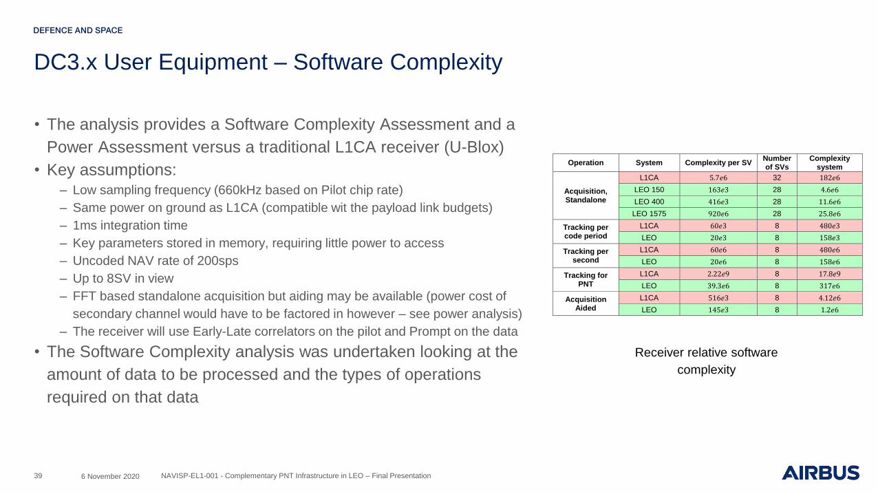
• The analysis provides a Software Complexity Assessment and a
Power Assessment versus a traditional L1CA receiver (U-Blox)
• Key assumptions:– Low sampling frequency (660kHz based on Pilot chip rate)
– Same power on ground as L1CA (compatible wit the payload link budgets)
– 1ms integration time
– Key parameters stored in memory, requiring little power to access
– Uncoded NAV rate of 200sps
– Up to 8SV in view
– FFT based standalone acquisition but aiding may be available (power cost of
secondary channel would have to be factored in however – see power analysis)
– The receiver will use Early-Late correlators on the pilot and Prompt on the data
• The Software Complexity analysis was undertaken looking at the
amount of data to be processed and the types of operations
required on that data
39
Operation System Complexity per SV Number of SVs
Complexity system
Acquisition, Standalone
L1CA 5.7𝑒6 32 182𝑒6
LEO 150 163𝑒3 28 4.6𝑒6
LEO 400 416𝑒3 28 11.6𝑒6
LEO 1575 920𝑒6 28 25.8𝑒6
Tracking per code period
L1CA 60𝑒3 8 480𝑒3
LEO 20𝑒3 8 158𝑒3
Tracking per second
L1CA 60𝑒6 8 480𝑒6
LEO 20𝑒6 8 158𝑒6
Tracking for PNT
L1CA 2.22𝑒9 8 17.8𝑒9
LEO 39.3𝑒6 8 317𝑒6
Acquisition Aided
L1CA 516𝑒3 8 4.12𝑒6
LEO 145𝑒3 8 1.2𝑒6
Receiver relative software
complexity
6 November 2020 NAVISP-EL1-001 - Complementary PNT Infrastructure in LEO – Final Presentation

DC3.x User Equipment
• Two methods were used to assess likely power usage:– Method 1: Scaling total power of the exemplar U-Blox unit (already a highly
optimised ASIC) by the timeline for the LEO receiver operations, taking
advantage of the LEO signal improvements. This gives the energy to get to a
fix.
– Method 2: Take the tracking power quoted by U-Blox, and split that power
between the grabbing and processing operations, and from that extrapolate
the power required per arithmetic operation
• From the analysis it is clear that he cost of aiding is too high for
LEO, or put another way, the benefit of the faster, shorter NAV
messages mean that aiding is unnecessary.– The two different LEO frequencies require very similar computations, as even
the relatively short (2s) tracking takes a lot more operations than the
acquisition.
• Method 2 indicates that the unaided LEO system may just meet
the DC3 energy-per-fix FOM
40
Aided Acquisition LEO L1CA
Downloading of aiding data 31mJ 53mJ
Aided start 42mJ 100mJ
Total 60mJ 153mJ
Unaided Acquisition LEO L1CA
Acquisition of Doppler and code offsets
150MHz 400MHz L1 250mJ
55mJ 62.5mJ 78.5mJ
Tracking of navigation data 20mJ 300mJ
Total 150MHz 400MHz L1 550mJ
Grabber / SW split
L1CA unaided
L1CA aided
LEO 150MHz unaided
LEO 150MHz aided
LEO 400MHz unaided
LEO 400MHz aided
75 – 25 370.9 53.8 16.7 31.3 16.7 31.3
50 – 50 371.9 53.8 13.3 31.3 13.4 31.3
25 - 75 372.8 53.8 10 31.3 10.1 31.3
Method 1: Energy per fix
Method 2: Energy per fix
6 November 2020 NAVISP-EL1-001 - Complementary PNT Infrastructure in LEO – Final Presentation

DC3.x User Equipment - Antennas
• The early analysis had not looked in detail at the practicalities of
building the UE for this DC.
• Whip antennas would provide the best performance for the link
budget but are impractical for most users due to the physical
size.
• Smaller “stubby” antennas have been identified, suitable for the
selected frequency bands
• These are much easier to integrate but suffer from lower
performance and so the link budget would be slightly impacted.
41 8 December 2020 NAVISP-EL1-001 - Complementary PNT Infrastructure in LEO – Final Presentation

DC3.x User Equipment – PPP performance
• The system cannot meet the UC6 accuracy requirement without
some form of PPP/RTK
• These systems suffer from slow start-up (convergence) times and
poor recovery (re-convergence) times after interruption
• Convergence times in excess of LEO visibility period will not work
• Analysis shows that the addition of a LEO complementary system
can improve on both of these parameters
• Proposed system has 224 satellites – performance between the 192L
and 288L cases shown
• Startup (convergence) time of ~2 minutes
• Likely acceptable to users
• Is within the visibility period of the LEO satellites
• A UE with an in-built INS of only moderate performance (similar to
current smartphone INS) would have sufficient ride through and
good enough re-convergence for many CAV signal interruption
scenarios
8 December 2020 NAVISP-EL1-001 - Complementary PNT Infrastructure in LEO – Final Presentation42
Initial PPP convergence time,
stationary receiver showing
accuracy in the UC6 FOM
range but unacceptable
convergence time
PPP re-convergence
times after interruptions
from overpasses
Impact of complementary
LEO constellation size on
PPP convergence time

DC3.x Ground Segment
• The DC3.x Ground Segment uses very similar architecture to that from
MEO
– A set of Uplink Stations to uplink the NAV message
– Ground Monitoring Receivers to confirm system operation
– A control centre to derive the NAV data to be uplinked
• An assessment of the data volumes including a modified set of NAV
messages was undertaken
– S-band can support an additional 2kbps channel
– Complementary signals (S-band and UHF/VHF) can consider optimised NAV
messages as backwards compatibility with L-band is not required
– Transmission of only the F/NAV message
– Optimised ephemeris for “closest 8” SV to minimise data volume and TTFF
– Deletion of per-SV clock parameters (as they use the MEO clocks)
• A total of between 1-3kbps is needed to support the uplink depending on
the S-band channel usage
– This is well within the ArrOW platform link of 28kbps uplink and 50kbps
downlink
43 8 December 2020 NAVISP-EL1-001 - Complementary PNT Infrastructure in LEO – Final Presentation

DC3.x Ground Segment
• Since there is no need to rapidly update the on-board clock data (a driver
for MEO uplink rates) the platform TMTC system can be used for both
TMTC and Mission data
• ~17 sites required for permanent constellation visibility
– Locations for some of these may be difficult due to political constraints
• A small antenna is required (<1.5m) to meet the link budget hence
reducing Ground Station unit costs
– X/Y antenna recommended to minimise tracking issues at LEO
• Multiple heads per site recommended to contact multiple satellites
• Phased arrays becoming an option
– Reduce required ground footprint and allow multiple, simultaneous contacts but
little operational experience so far
44 8 December 2020 NAVISP-EL1-001 - Complementary PNT Infrastructure in LEO – Final Presentation
DC3.x Ground Segment
8 December 2020 NAVISP-EL1-001 - Complementary PNT Infrastructure in LEO – Final Presentation45
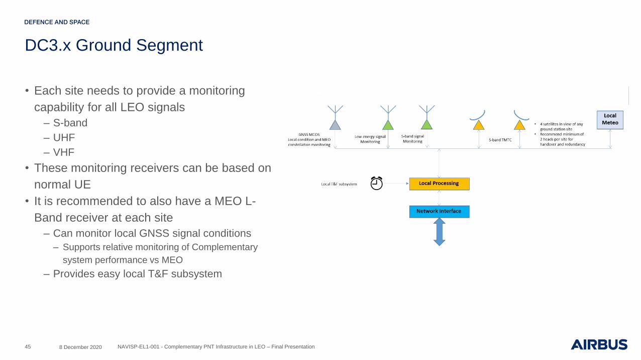
• Each site needs to provide a monitoring
capability for all LEO signals
– S-band
– UHF
– VHF
• These monitoring receivers can be based on
normal UE
• It is recommended to also have a MEO L-
Band receiver at each site
– Can monitor local GNSS signal conditions
– Supports relative monitoring of Complementary
system performance vs MEO
– Provides easy local T&F subsystem
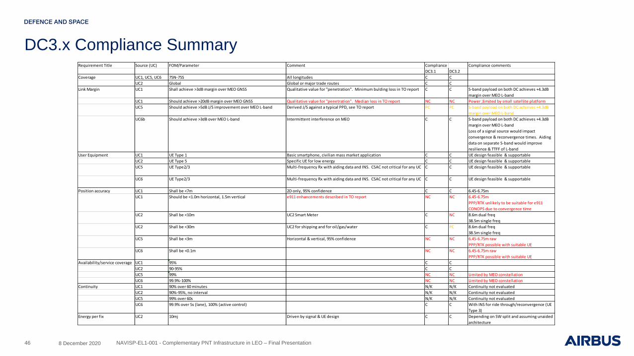
DC3.x Compliance Summary
8 December 2020 NAVISP-EL1-001 - Complementary PNT Infrastructure in LEO – Final Presentation46
Requirement Title Source (UC) FOM/Parameter Comment Compliance Compliance comments
DC3.1 DC3.2
Coverage UC1, UC5, UC6 75N-75S All longitudes C C
UC2 Global Global or major trade routes C C
Link Margin UC1 Shall achieve >3dB margin over MEO GNSS Qualitative value for "penetration". Minimum bulding loss in TO report C C S-band payload on both DC achieves +4.3dB
margin over MEO L-band
UC1 Should achieve >20dB margin over MEO GNSS Qualitative value for "penetration". Median loss in TO report NC NC Power ;limited by small satellite platform
UC5 Should achieve >5dB J/S improvement over MEO L-band Derived J/S against a typical PPD, see TO report PC PC S-band payload on both DC achieves +4.3dB
margin over MEO L-band
UC6b Should achieve >3dB over MEO L-band Intermittent interference on MEO C C S-band payload on both DC achieves +4.3dB
margin over MEO L-band
Loss of a signal source would impact
convergence & reconvergence times. Aiding
data on separate S-band would improve
resilience & TTFF of L-band
User Equipment UC1 UE Type 1 Basic smartphone, civilian mass market application C C UE design feasible & supportable
UC2 UE Type 5 Specific UE for low energy C C UE design feasible & supportable
UC5 UE Type2/3 Multi-frequency Rx with aiding data and INS. CSAC not critical for any UC C C UE design feasible & supportable
UC6 UE Type2/3 Multi-frequency Rx with aiding data and INS. CSAC not critical for any UC C C UE design feasible & supportable
Position accuracy UC1 Shall be <7m 2D only, 95% confidence C C 6.45-6.75m
UC1 Should be <1.0m horizontal, 1.5m vertical e911 enhancements described in TO report NC NC 6.45-6.75m
PPP/RTK unlikely to be suitable for e911
CONOPS due to convergence time
UC2 Shall be <10m UC2 Smart Meter C NC 8.6m dual freq
38.5m single freq
UC2 Shall be <30m UC2 for shipping and for oil/gas/water C PC 8.6m dual freq
38.5m single freq
UC5 Shall be <3m Horizontal & vertical, 95% confidence NC NC 6.45-6.75m raw
PPP/RTK possible with suitable UE
UC6 Shall be <0.1m NC NC 6.45-6.75m raw
PPP/RTK possible with suitable UE
Availability/service coverage UC1 95% C C
UC2 90-95% C C
UC5 99% NC NC Limited by MEO constellation
UC6 99.9%-100% NC NC Limited by MEO constellation
Continuity UC1 90% over 60 minutes N/K N/K Continuity not evaluated
UC2 90%-95%, no interval N/K N/K Continuity not evaluated
UC5 99% over 60s N/K N/K Continuity not evaluated
UC6 99.9% over 5s (lane), 100% (active control) C C With INS for ride through/reconvergence (UE
Type 3)
Energy per fix UC2 10mj Driven by signal & UE design C C Depending on SW split and assuming unaided
architecture

DC3.x Conclusions
• The UHF/VHF payload cannot fully meet the Use Case FOM
– Ionospheric impacts prevent accuracy achievement
– UE design barely meets the targeted energy-per-fix
– Additional UE antenna losses for desired form-factor will further limit performance
• Frequency availability is a concern for UHF/VHF
• The remaining DC payload power is barely sufficient for the S-band system
– Provides no meaningful power margin over the extant MEO L-band signal
– Limited excess power for building penetration or jammer advantage
– Larger satellites possible but significantly impact system cost (per unit SV cost plus launch costs)
• The S-band signal and number of LEO satellites is promising for UC6 CAV
– Enables improved PPP performance
– PPP enables achievement of UC6 positional accuracy FOM
– Increased numbers of satellites reduces convergence and re-convergence time
– Simple UE enhancements with moderate INS allow for ride-through of capability
47 8 December 2020 NAVISP-EL1-001 - Complementary PNT Infrastructure in LEO – Final Presentation

Thank you