nema ts2-2003- traffic controller assemb
TRANSCRIPT
7/30/2019 NEMA TS2-2003- Traffic Controller Assemb
http://slidepdf.com/reader/full/nema-ts2-2003-traffic-controller-assemb 1/246
NEMA Standards Publication TS 2-2003
Traffic Controller Assemblies
with NTCIP Requirements
Published by
National Electrical Manufacturers Association
1300 N. 17th StreetRosslyn, Virginia 22209
© Copyright 2003 by the National Electrical Manufacturers Association. All rights including translation intoother languages, reserved under the Universal Copyright Convention, the Berne Convention or theProtection of Literary and Artistic Works, and the International and Pan American Copyright Conventions.

7/30/2019 NEMA TS2-2003- Traffic Controller Assemb
http://slidepdf.com/reader/full/nema-ts2-2003-traffic-controller-assemb 2/246
7/30/2019 NEMA TS2-2003- Traffic Controller Assemb
http://slidepdf.com/reader/full/nema-ts2-2003-traffic-controller-assemb 3/246
TS 2-2003Page i
© NEMA
CONTENTS Page
Foreword................................................................................................................................................... xviii
Scope..........................................................................................................................................................xix
HISTORY ...................................................................................................................................................xxii
TS 2-1998 UPDATE..................................................................................................................................xxiv
TS 2-2003 UPDATE...................................................................................................................................xxv
SECTION 1 DEFINITIONS ........................................................................................................................1-1
1.1 CONTROL EQUIPMENT................................................................................................................1-11.1.1 AUXILIARY EQUIPMENT......................................................................................................1-11.1.2 BARRIER ...............................................................................................................................1-1
1.1.3 CABINET................................................................................................................................1-11.1.4 CALL ......................................................................................................................................1-1
1.1.4.1 SERVICEABLE CONFLICTING CALL .........................................................................1-11.1.5 CHECK ...................................................................................................................................1-11.1.6 CONNECTOR......................................................................................................................... 1-1
1.1.6.1 NOT USED CONNECTIONS.........................................................................................1-11.1.6.2 RESERVED CONNECTIONS........................................................................................1-21.1.6.3 SPARE CONNECTIONS ...............................................................................................1-2
1.1.7 CONTROLLER ASSEMBLY..................................................................................................1-21.1.7.1 FLASHER CONTROLLER ASSEMBLY .......................................................................1-21.1.7.2 FULL-TRAFFIC-ACTUATED CONTROLLER ASSEMBLY .........................................1-21.1.7.3 ISOLATED CONTROLLER ASSEMBLY......................................................................1-21.1.7.4 MASTER CONTROLLER ASSEMBLY .........................................................................1-2
1.1.7.5 MASTER-SECONDARY CONTROLLER ASSEMBLY.................................................1-21.1.7.6 OCCUPANCY CONTROLLER ASSEMBLY (LANE-OCCUPANCY CONTROLLER ORDEMAND CONTROLLER AND PRESENCE CONTROLLER).................................................1-21.1.7.7 PEDESTRIAN-ACTUATED CONTROLLER ASSEMBLY............................................1-21.1.7.8 PRETIMED CONTROLLER ASSEMBLY......................................................................1-21.1.7.9 SECONDARY CONTROLLER ASSEMBLY (SLAVE)..................................................1-21.1.7.10 SEMI-TRAFFIC-ACTUATED CONTROLLER ASSEMBLY........................................1-31.1.7.11 TRAFFIC-ACTUATED CONTROLLER ASSEMBLY..................................................1-3
1.1.8 CONTROLLER UNIT .............................................................................................................1-31.1.8.1 DIGITAL CONTROLLER UNIT......................................................................................1-31.1.8.2 MULTI-RING CONTROLLER UNIT...............................................................................1-31.1.8.3 SINGLE-RING CONTROLLER UNIT ............................................................................1-3
1.1.9 COORDINATION.................................................................................................................... 1-31.1.10 COORDINATOR...................................................................................................................1-31.1.11 CYCLE.................................................................................................................................. 1-3
1.1.11.1 CYCLE LENGTH .........................................................................................................1-31.1.12 DENSITY..............................................................................................................................1-31.1.13 DETECTOR..........................................................................................................................1-31.1.14 DEVICE ................................................................................................................................1-3
1.1.14.1 ELECTROMECHANICAL DEVICE .............................................................................1-31.1.14.2 ELECTRONIC DEVICE................................................................................................1-31.1.14.3 SOLID-STATE DEVICE...............................................................................................1-4
1.1.15 DIAL .....................................................................................................................................1-4
7/30/2019 NEMA TS2-2003- Traffic Controller Assemb
http://slidepdf.com/reader/full/nema-ts2-2003-traffic-controller-assemb 4/246
TS 2-2003Page ii
© NEMA
1.1.16 DWELL .................................................................................................................................1-41.1.17 EXTENSION, UNIT...............................................................................................................1-41.1.18 ENTRY..................................................................................................................................1-4
1.1.18.1 DUAL ENTRY ..............................................................................................................1-41.1.18.2 SINGLE ENTRY...........................................................................................................1-4
1.1.19 FLASHER.............................................................................................................................1-41.1.20 FORCE OFF......................................................................................................................... 1-41.1.21 GAP REDUCTION................................................................................................................1-41.1.22 HOLD....................................................................................................................................1-41.1.23 INTERCONNECT.................................................................................................................1-41.1.24 INTERVAL............................................................................................................................1-4
1.1.24.1 MINIMUM GREEN INTERVAL ....................................................................................1-41.1.24.2 PEDESTRIAN CLEARANCE INTERVAL ...................................................................1-41.1.24.3 RED CLEARANCE INTERVAL ...................................................................................1-41.1.24.4 SEQUENCE, INTERVAL .............................................................................................1-51.1.24.5 YELLOW CHANGE INTERVAL ..................................................................................1-5
1.1.25 MANUAL ..............................................................................................................................1-51.1.25.1 MANUAL OPERATION ...............................................................................................1-51.1.25.2 MANUAL PUSHBUTTON............................................................................................1-5
1.1.26 MAXIMUM GREEN ..............................................................................................................1-51.1.27 MEMORY.............................................................................................................................. 1-5
1.1.27.1 DETECTOR MEMORY ................................................................................................1-51.1.27.2 NONLOCKING MEMORY............................................................................................1-51.1.27.3 NON-VOLATILE MEMORY.........................................................................................1-51.1.27.4 VOLATILE MEMORY ..................................................................................................1-51.1.27.5 RANDOM ACCESS MEMORY (RAM) ........................................................................1-51.1.27.6 READ ONLY MEMORY (ROM) ...................................................................................1-51.1.27.7 PROGRAMMABLE READ ONLY MEMORY (PROM)................................................1-51.1.27.8 PROGRAMMABLE READ ONLY MEMORY (EPROM)..............................................1-5
1.1.28 MALFUNCTION MANAGEMENT UNIT...............................................................................1-51.1.29 MODULAR DESIGN.............................................................................................................1-51.1.30 OFFSET................................................................................................................................1-6
1.1.31 OMIT, PHASE (SPECIAL SKIP, FORCE SKIP)..................................................................1-61.1.32 OVERLAP ............................................................................................................................1-61.1.33 PASSAGE TIME................................................................................................................... 1-61.1.34 PATTERN............................................................................................................................. 1-61.1.35 PHASE .................................................................................................................................1-6
1.1.35.1 TRAFFIC PHASE.........................................................................................................1-61.1.35.2 CONFLICTING PHASES.............................................................................................1-61.1.35.3 NONCONFLICTING PHASE .......................................................................................1-61.1.35.4 PEDESTRIAN PHASE.................................................................................................1-61.1.35.5 PHASE SEQUENCE....................................................................................................1-61.1.35.6 PARENT PHASE .........................................................................................................1-61.1.35.7 VEHICULAR PHASE...................................................................................................1-6
1.1.36 PORTION .............................................................................................................................1-6
1.1.36.1 EXTENSIBLE PORTION .............................................................................................1-61.1.36.2 INITIAL PORTION .......................................................................................................1-61.1.36.3 INTERVAL PORTION..................................................................................................1-7
1.1.37 PREEMPTION...................................................................................................................... 1-71.1.38 PREEMPTOR, TRAFFIC CONTROLLER ...........................................................................1-71.1.39 PREFERRED SEQUENCE ..................................................................................................1-71.1.40 PROGRESSION...................................................................................................................1-71.1.41 RED INDICATION, MINIMUM (RED REVERT) ...................................................................1-71.1.42 REST ....................................................................................................................................1-71.1.43 RING.....................................................................................................................................1-7
7/30/2019 NEMA TS2-2003- Traffic Controller Assemb
http://slidepdf.com/reader/full/nema-ts2-2003-traffic-controller-assemb 5/246
TS 2-2003Page iii
© NEMA
1.1.44 SPLIT....................................................................................................................................1-71.1.45 SUPPRESSORS ..................................................................................................................1-7
1.1.45.1 SUPPRESSOR, RADIO INTERFERENCE..................................................................1-71.1.45.2 SUPPRESSOR, TRANSIENT......................................................................................1-7
1.1.46 SWITCH................................................................................................................................1-8
1.1.46.1 AUTO/MANUAL SWITCH ...........................................................................................1-81.1.46.2 FLASH CONTROL SWITCH .......................................................................................1-81.1.46.3 POWER LINE SWITCH (DISCONNECT SWITCH).....................................................1-81.1.46.4 RECALL SWITCH........................................................................................................1-81.1.46.5 SIGNAL LOAD SWITCH .............................................................................................1-81.1.46.6 SIGNAL SHUT-DOWN SWITCH.................................................................................1-8
1.1.47 TIME BASE CONTROL .......................................................................................................1-81.1.48 TERMINALS, FIELD ............................................................................................................1-81.1.49 TIMING.................................................................................................................................1-8
1.1.49.1 ANALOG TIMING ........................................................................................................1-81.1.49.2 CONCURRENT TIMING..............................................................................................1-81.1.49.3 DIGITAL TIMING..........................................................................................................1-81.1.49.4 TIMING PLAN ..............................................................................................................1-8
1.1.50 YIELD ...................................................................................................................................1-81.2 DETECTORS..................................................................................................................................1-8
1.2.1 ACTUATION........................................................................................................................... 1-81.2.2 ANTENNA ..............................................................................................................................1-81.2.3 CALL ......................................................................................................................................1-91.2.4 DETECTION...........................................................................................................................1-9
1.2.4.1 ADVISORY DETECTION...............................................................................................1-91.2.4.2 PASSAGE DETECTION................................................................................................1-91.2.4.3 PRESENCE DETECTION.............................................................................................. 1-9
1.2.5 DETECTOR............................................................................................................................ 1-91.2.5.1 BIDIRECTIONAL DETECTOR ......................................................................................1-91.2.5.2 CALLING DETECTOR...................................................................................................1-91.2.5.3 CLASSIFICATION DETECTOR ....................................................................................1-91.2.5.4 DIRECTIONAL DETECTOR..........................................................................................1-9
1.2.5.5 EXTENSION DETECTOR.............................................................................................. 1-91.2.5.6 INFRARED DETECTOR................................................................................................1-91.2.5.7 LIGHT-SENSITIVE DETECTOR....................................................................................1-91.2.5.8 LOOP DETECTOR ........................................................................................................1-91.2.5.9 MAGNETIC DETECTOR ...............................................................................................1-91.2.5.10 MAGNETOMETER DETECTOR................................................................................1-101.2.5.11 NONDIRECTIONAL DETECTOR..............................................................................1-101.2.5.12 PEDESTRIAN DETECTOR .......................................................................................1-101.2.5.13 PNEUMATIC DETECTOR .........................................................................................1-101.2.5.14 PRESSURE-SENSITIVE DETECTOR.......................................................................1-101.2.5.15 RADAR DETECTOR..................................................................................................1-101.2.5.16 SYSTEM DETECTOR................................................................................................1-101.2.5.17 SIDE-FIRE DETECTOR.............................................................................................1-10
1.2.5.18 SOUND-SENSITIVE VEHICLE DETECTOR.............................................................1-101.2.5.19 ULTRASONIC DETECTOR.......................................................................................1-10
1.2.6 DETECTOR MODE..............................................................................................................1-101.2.7 INDUCTIVE LOOP DETECTOR SYSTEM ..........................................................................1-101.2.8 INDUCTIVE LOOP DETECTOR UNIT.................................................................................1-101.2.9 LEAD-IN CABLE..................................................................................................................1-111.2.10 OUTPUT.............................................................................................................................1-11
1.2.10.1 EXTENSION OUTPUT...............................................................................................1-111.2.10.2 DELAYED OUTPUT ..................................................................................................1-11
1.2.11 PROBE...............................................................................................................................1-11
7/30/2019 NEMA TS2-2003- Traffic Controller Assemb
http://slidepdf.com/reader/full/nema-ts2-2003-traffic-controller-assemb 6/246
TS 2-2003Page iv
© NEMA
1.2.12 SENSOR.............................................................................................................................1-111.2.13 VEHICLE DETECTOR SYSTEM .......................................................................................1-111.2.14 ZONE OF DETECTION (SENSING ZONE) .......................................................................1-11
1.3 SIGNAL ........................................................................................................................................1-111.4 CROSS-REFERENCE DEFINITIONS..........................................................................................1-12
SECTION 2 ENVIRONMENTAL REQUIREMENTS..................................................................................2-1
2.1 ENVIRONMENTAL AND OPERATING STANDARDS .................................................................2-12.1.1 DEFINITIONS OF MAJOR UNITS OF THE CONTROLLER ASSEMBLY ...........................2-12.1.2 OPERATING VOLTAGE........................................................................................................2-12.1.3 OPERATING FREQUENCY...................................................................................................2-12.1.4 POWER INTERRUPTION......................................................................................................2-1
2.1.4.1 FIELD TERMINAL OUTPUTS.......................................................................................2-12.1.5 TEMPERATURE AND HUMIDITY.........................................................................................2-2
2.1.5.1 AMBIENT TEMPERATURE...........................................................................................2-22.1.5.2 HUMIDITY ......................................................................................................................2-2
2.1.6 TRANSIENTS, POWER SERVICE........................................................................................2-22.1.6.1 HIGH-REPETITION NOISE TRANSIENTS...................................................................2-22.1.6.2 LOW-REPETITION HIGH-ENERGY TRANSIENTS......................................................2-3
2.1.7 TRANSIENTS, INPUT-OUTPUT TERMINALS......................................................................2-32.1.8 NONDESTRUCT TRANSIENT IMMUNITY ...........................................................................2-32.1.9 VIBRATION............................................................................................................................2-32.1.10 SHOCK.................................................................................................................................2-3
2.2 CONTROLLER UNIT TESTS.........................................................................................................2-32.2.1 TIMING ACCURACY..............................................................................................................2-4
2.2.1.1 DEVIATION....................................................................................................................2-42.2.1.2 SETABILITY AND REPEATABILITY............................................................................2-4
2.2.2 TIMING...................................................................................................................................2-42.2.3 VIBRATION............................................................................................................................2-42.2.4 SHOCK................................................................................................................................... 2-42.2.5 TEST FACILITIES..................................................................................................................2-42.2.6 TEST UNIT .............................................................................................................................2-4
2.2.7 TEST PROCEDURE: TRANSIENTS, TEMPERATURE, VOLTAGE, AND HUMIDITY........2-42.2.7.1 TEST A: PLACEMENT IN ENVIRONMENTAL CHAMBER AND CHECK-OUT OFHOOK-UP...................................................................................................................................2-42.2.7.2 TEST B: TRANSIENT TESTS (POWER SERVICE) .....................................................2-52.2.7.3 TEST C—LOW-TEMPERATURE LOW-VOLTAGE TESTS.........................................2-72.2.7.4 TEST D—LOW-TEMPERATURE HIGH-VOLTAGE TESTS ........................................2-82.2.7.5 TEST E—HIGH-TEMPERATURE HIGH-VOLTAGE TESTS........................................2-82.2.7.6 TEST F—HIGH-TEMPERATURE LOW-VOLTAGE TESTS.........................................2-92.2.7.7 TEST G—TEST TERMINATION.................................................................................... 2-92.2.7.8 TEST H—APPRAISAL OF EQUIPMENT UNDER TEST .............................................2-9
2.2.8 VIBRATION TEST................................................................................................................2-102.2.8.1 PURPOSE OF TEST....................................................................................................2-102.2.8.2 TEST EQUIPMENT REQUIREMENTS........................................................................2-10
2.2.8.3 RESONANT SEARCH.................................................................................................2-102.2.8.4 ENDURANCE TEST ....................................................................................................2-112.2.8.5 DISPOSITION OF EQUIPMENT UNDER TEST..........................................................2-11
2.2.9 SHOCK (IMPACT) TEST .....................................................................................................2-112.2.9.1 PURPOSE OF TEST....................................................................................................2-112.2.9.2 TEST EQUIPMENT REQUIREMENTS........................................................................2-112.2.9.3 TEST PROCEDURE ....................................................................................................2-132.2.9.4 DISPOSITION OF TEST UNIT.....................................................................................2-13
2.2.10 POWER INTERRUPTION TESTS .....................................................................................2-132.2.10.1 500-MILLISECOND POWER INTERRUPTION.........................................................2-13
7/30/2019 NEMA TS2-2003- Traffic Controller Assemb
http://slidepdf.com/reader/full/nema-ts2-2003-traffic-controller-assemb 7/246
TS 2-2003Page v
© NEMA
2.2.10.2 1000-MILLISECOND POWER INTERRUPTION.......................................................2-132.2.11 TIMING ACCURACY TESTS.............................................................................................2-14
2.2.11.1 SETABILITY...............................................................................................................2-142.2.11.2 REPEATABILITY.......................................................................................................2-14
2.3 MALFUNCTION MANAGEMENT UNIT TESTS..........................................................................2-14
2.3.1 TEST FACILITIES................................................................................................................2-142.3.2 STANDARD SETUP.............................................................................................................2-142.3.3 GROUND ISOLATION TEST...............................................................................................2-152.3.4 1500 PF INPUT TEST..........................................................................................................2-152.3.5 CONFLICT LOW VOLTAGE TEST .....................................................................................2-152.3.6 CONFLICT HIGH VOLTAGE TEST.....................................................................................2-152.3.7 RED INPUT TEST................................................................................................................2-152.3.8 MINIMUM YELLOW CHANGE/RED CLEARANCE INTERVAL .........................................2-162.3.9 PORT 1 TIMEOUT................................................................................................................2-162.3.10 DC VOLTAGE MONITORING............................................................................................2-162.3.11 MMU POWER FAILURE....................................................................................................2-172.3.12 PERMISSIVE PROGRAMMING ........................................................................................2-172.3.13 CONTINUOUS RESET ......................................................................................................2-172.3.14 TRANSIENT TESTS ..........................................................................................................2-17
2.4 TERMINAL AND FACILITIES TESTS .........................................................................................2-182.5 LOAD SWITCH TESTS................................................................................................................2-18
2.5.1 TEST PROCEDURE FOR PIV AND DV/DT TESTING........................................................2-182.6 FLASHER TESTS ........................................................................................................................2-19
2.6.1 TEST PROCEDURE FOR PIV AND DV/DT TESTING........................................................2-192.7 FLASH TRANSFER RELAY TESTS ...........................................................................................2-192.8 LOOP DETECTOR UNIT TESTS.................................................................................................2-20
2.8.1 ENVIRONMENTAL REQUIREMENTS................................................................................2-202.8.1.1 VOLTAGE, DC SUPPLY .............................................................................................2-202.8.1.2 TEMPERATURE AND HUMIDITY...............................................................................2-202.8.1.3 TRANSIENTS, DC POWERED UNITS........................................................................2-202.8.1.4 TRANSIENTS, LOOP DETECTOR INPUT TERMINALS ...........................................2-212.8.1.5 VIBRATION..................................................................................................................2-21
2.8.1.6 SHOCK.........................................................................................................................2-222.9 BUS INTERFACE UNIT TESTS...................................................................................................2-23
SECTION 3 CONTROLLER UNITS...........................................................................................................3-1
3.1 DEFINITIONS .................................................................................................................................3-13.1.1 CRC (CYCLIC REDUNDANCY CHECK)...............................................................................3-13.1.2 LOAD SWITCH DRIVER GROUP .........................................................................................3-1
3.2 PHYSICAL STANDARDS ..............................................................................................................3-13.2.1 DIMENSIONS.........................................................................................................................3-13.2.2 DESIGN .................................................................................................................................. 3-13.2.3 MATERIAL AND CONSTRUCTION OF RIGID PRINTED CIRCUIT ASSEMBLIES ............3-1
3.2.3.1 MATERIALS...................................................................................................................3-13.2.3.2 MATING SURFACES ....................................................................................................3-2
3.2.3.3 COMPONENT IDENTIFICATION ..................................................................................3-23.3 INTERFACE STANDARDS............................................................................................................3-2
3.3.1 PORT 1 PHYSICAL AND PROTOCOL .................................................................................3-23.3.1.1 CONNECTOR ................................................................................................................3-23.3.1.2 ELECTRICAL INTERFACE ...........................................................................................3-3
3.3.1.2.1 LOGIC GROUND AND EARTH GROUND ...........................................................3-33.3.1.2.2 DATA AND CLOCK LINKS...................................................................................3-3
3.3.1.3 DATA AND CLOCK COMMUNICATIONS PROTOCOL ..............................................3-43.3.1.4 INFORMATION FIELD FORMATS................................................................................3-7
3.3.1.4.1 PRIMARY STATION (CU) .....................................................................................3-8
7/30/2019 NEMA TS2-2003- Traffic Controller Assemb
http://slidepdf.com/reader/full/nema-ts2-2003-traffic-controller-assemb 8/246
TS 2-2003Page vi
© NEMA
3.3.1.4.1.1 TYPE 0 LOAD SWITCH DRIVERS....................................................................3-83.3.1.4.1.2 TYPE 1 MMU INPUTS / STATUS REQUEST..................................................3-113.3.1.4.1.3 TYPE 3 MMU PROGRAMMING REQUEST ....................................................3-113.3.1.4.1.4 TYPE 9 DATE AND TIME BROADCAST ........................................................3-113.3.1.4.1.5 TYPE 10 TF BIU #1 OUTPUTS / INPUTS REQUEST .....................................3-13
3.3.1.4.1.6 TYPE 11 TF BIU #2 OUTPUTS / INPUTS REQUEST .....................................3-143.3.1.4.1.7 TYPE 12 TF BIU #3 OUTPUTS / INPUTS REQUEST .....................................3-153.3.1.4.1.8 TYPE 13 TF BIU #4 OUTPUTS / INPUTS REQUEST .....................................3-153.3.1.4.1.9 TYPE 18 OUTPUT TRANSFER FRAME .........................................................3-163.3.1.4.1.10 TYPE 20 DR BIU #1 CALL DATA REQUEST ...............................................3-163.3.1.4.1.11 TYPES 21–23 DR BIUS #2-4 CALL DATA REQUEST.................................3-163.3.1.4.1.12 TYPE 24 DR BIU #1 RESET / DIAGNOSTIC REQUEST..............................3-163.3.1.4.1.13 TYPE 25-27 DR BIUS #2-4 RESET / DIAGNOSTIC REQUEST ...................3-173.3.1.4.1.14 TYPE 30 DIAGNOSTIC REQUEST................................................................3-173.3.1.4.1.15 TYPE 40 POLL FOR SERVICE......................................................................3-173.3.1.4.1.16 TYPE 41 RESERVED.....................................................................................3-173.3.1.4.1.17 TYPE 42 SECONDARY DESTINATION MESSAGE .....................................3-173.3.1.4.1.18 TYPE 43 SECONDARY EXCHANGE STATUS.............................................3-183.3.1.4.2 SECONDARY STATIONS...................................................................................3-193.3.1.4.2.1 TYPE 128 MMU (TYPE 0 ACK) .......................................................................3-193.3.1.4.2.2 TYPE 129 MMU INPUTS/STATUS (TYPE 1 ACK)..........................................3-193.3.1.4.2.3 TYPE 131 MMU PROGRAMMING (TYPE 3 ACK) ..........................................3-213.3.1.4.2.4 TYPE 138 TF BIU #1 INPUTS (TYPE 10 ACK) ...............................................3-243.3.1.4.2.5 TYPES 139–141 TF BIU #2-4 INPUTS (TYPE 11-13 ACK) ............................3-253.3.1.4.2.6 TYPE 148 DR BIU #1 CALL DATA (TYPE 20 ACK).......................................3-253.3.1.4.2.7 TYPES 149–151 DR BIU #2-4 CALL DATA (TYPE 21-23 ACK)....................3-313.3.1.4.2.8 TYPE 152 DR BIU #1 DIAGNOSTIC (TYPE 24 ACK) .....................................3-313.3.1.4.2.9 TYPES 153–155 DR BIU #2-4 DIAGNOSTIC (TYPE 25-27 ACK) ..................3-333.3.1.4.2.10 TYPE 158 DIAGNOSTICS (TYPE 30 ACK) ...................................................3-343.3.1.4.2.11 TYPE 168 NO SERVICE REQUIRED (TYPE 40 ACK)..................................3-353.3.1.4.2.12 TYPE 169 SECONDARY SOURCE MESSAGE (TYPE 40 ACK) .................3-353.3.1.4.2.13 TYPE 170 SECONDARY NEGATIVE ACKNOWLEDGE (TYPE 42 NACK).3-36
3.3.1.4.2.14 TYPE 171 SECONDARY ACKNOWLEDGE (TYPE 42/43 ACK)..................3-363.3.1.4.3 SECONDARY TO SECONDARY MESSAGES...................................................3-36
3.3.1.5 FRAME TIMING...........................................................................................................3-373.3.1.5.1 PRIMARY STATION............................................................................................3-373.3.1.5.2 SECONDARY STATIONS...................................................................................3-383.3.1.5.3 HANDSHAKING ..................................................................................................3-383.3.1.5.4 COMMAND FRAME SCHEDULING ...................................................................3-39
3.3.2 PORT 2 INTERFACE...........................................................................................................3-403.3.2.1 UNIT TO PRINTER......................................................................................................3-403.3.2.2 UNIT TO PERSONAL COMPUTER ............................................................................3-41
3.3.3 PORT 3 SYSTEM INTERFACE ...........................................................................................3-413.3.3.1 CONNECTOR ..............................................................................................................3-413.3.3.2 INTERFACE.................................................................................................................3-41
3.3.3.2.1 TRANSMISSION METHOD.................................................................................3-413.3.3.2.2 TRANSMITTER CHARACTERISTICS................................................................3-413.3.3.2.3 RECEIVER CHARACTERISTICS .......................................................................3-41
3.3.4 TYPE 1—INTERFACE STANDARDS .................................................................................3-413.3.5 TYPE 2—INTERFACE STANDARDS .................................................................................3-42
3.3.5.1 ELECTRICAL LIMITS OF INPUT / OUTPUT TERMINATIONS .................................3-423.3.5.1.1 LOGIC LEVELS...................................................................................................3-423.3.5.1.2 TRANSIENT IMMUNITY......................................................................................3-423.3.5.1.3 INPUTS................................................................................................................3-423.3.5.1.4 OUTPUTS ............................................................................................................3-42
7/30/2019 NEMA TS2-2003- Traffic Controller Assemb
http://slidepdf.com/reader/full/nema-ts2-2003-traffic-controller-assemb 9/246
TS 2-2003Page vii
© NEMA
3.3.5.2 PIN CONNECTIONS....................................................................................................3-433.3.5.2.1 CONNECTORS USED.........................................................................................3-433.3.5.2.2 INPUT / OUTPUT CONNECTOR PIN TERMINATIONS.....................................3-43
3.3.6 NTCIP REQUIREMENTS.....................................................................................................3-463.4 PRETIMED CONTROL.................................................................................................................3-49
3.4.1 DEFINITIONS.......................................................................................................................3-493.4.1.1 SIGNAL PLAN .............................................................................................................3-493.4.2 GENERAL ............................................................................................................................3-49
3.4.2.1 TIMING PLANS............................................................................................................3-493.4.2.1.1 CYCLES...............................................................................................................3-503.4.2.1.2 SPLITS.................................................................................................................3-50
3.4.2.2 INTERVALS .................................................................................................................3-503.4.2.3 SIGNAL PLANS...........................................................................................................3-50
3.4.2.3.1 MINIMUM TIME ...................................................................................................3-503.4.2.3.2 LOAD SWITCH DRIVER CONDITION................................................................3-503.4.2.3.3 TIMING PLAN TRANSFER .................................................................................3-503.4.2.3.4 SIGNAL PLAN TRANSFER................................................................................3-503.4.2.3.5 VARIABLE INTERVAL........................................................................................3-503.4.2.3.6 AUTOMATIC FLASH...........................................................................................3-513.4.2.3.7 ACTUATED INTERVAL(S)..................................................................................3-51
3.4.2.4 OFFSET .......................................................................................................................3-513.4.2.5 SYNC MONITOR..........................................................................................................3-513.4.2.6 MANUAL CONTROL...................................................................................................3-513.4.2.7 FREE MODE................................................................................................................3-51
3.4.3 INITIALIZATION...................................................................................................................3-523.4.4 ACTUATED MOVEMENTS..................................................................................................3-52
3.4.4.1 PROVISION FOR STORING A DEMAND...................................................................3-523.4.4.2 PLACEMENT OF VEHICLE RECALL .........................................................................3-523.4.4.3 PLACEMENT OF PEDESTRIAN RECALL .................................................................3-52
3.4.5 EXTERNAL INTERFACE.....................................................................................................3-523.4.5.1 PIN CONNECTIONS....................................................................................................3-523.4.5.2 INPUTS ........................................................................................................................3-54
3.4.5.3 OUTPUTS ....................................................................................................................3-583.4.6 PRIORITY OF INPUT FUNCTIONS.....................................................................................3-603.4.7 INDICATIONS ......................................................................................................................3-60
3.5 ACTUATED CONTROL ...............................................................................................................3-613.5.1 DEFINITIONS.......................................................................................................................3-61
3.5.1.1 RING.............................................................................................................................3-613.5.1.2 BARRIER (COMPATIBIL ITY LINE) ............................................................................3-613.5.1.3 MULTI-RING CONTROLLER UNIT.............................................................................3-613.5.1.4 SINGLE-RING CONTROLLER UNIT ..........................................................................3-623.5.1.5 DUAL ENTRY ..............................................................................................................3-623.5.1.6 SINGLE ENTRY...........................................................................................................3-623.5.1.7 PEDESTRIAN RECYCLE............................................................................................3-623.5.1.8 PREFERRED SEQUENCE..........................................................................................3-62
3.5.2 GENERAL ............................................................................................................................3-623.5.2.1 PIN CONNECTIONS....................................................................................................3-63
3.5.3 PER PHASE.........................................................................................................................3-663.5.3.1 TIME SETTINGS..........................................................................................................3-663.5.3.2 PHASE INTERVALS....................................................................................................3-663.5.3.3 PHASE SELECTION POINTS.....................................................................................3-723.5.3.4 PROVISION FOR STORING A DEMAND...................................................................3-723.5.3.5 PLACEMENT OF MAXIMUM RECALL .......................................................................3-723.5.3.6 PLACEMENT OF MINIMUM RECALL ........................................................................3-723.5.3.7 PLACEMENT OF PEDESTRIAN RECALL .................................................................3-72
7/30/2019 NEMA TS2-2003- Traffic Controller Assemb
http://slidepdf.com/reader/full/nema-ts2-2003-traffic-controller-assemb 10/246
TS 2-2003Page viii
© NEMA
3.5.3.8 PLACEMENT OF CALL AT PHASE TERMINATION.................................................3-723.5.3.9 CONDITIONAL SERVICE............................................................................................3-723.5.3.10 AUTOMATIC PEDESTRIAN CLEARANCE..............................................................3-733.5.3.11 INPUTS ......................................................................................................................3-733.5.3.12 OUTPUTS ..................................................................................................................3-73
3.5.4 PER RING ............................................................................................................................3-743.5.4.1 INPUTS ........................................................................................................................3-743.5.4.2 OUTPUTS ....................................................................................................................3-75
3.5.5 PER UNIT .............................................................................................................................3-763.5.5.1 INITIALIZATION...........................................................................................................3-763.5.5.2 SIMULTANEOUS GAP OUT .......................................................................................3-763.5.5.3 DUAL ENTRY ..............................................................................................................3-773.5.5.4 ALTERNATE SEQUENCES........................................................................................3-773.5.5.5 INPUTS ........................................................................................................................3-783.5.5.6 OUTPUTS ....................................................................................................................3-823.5.5.7 RED REVERT ..............................................................................................................3-83
3.5.6 PRIORITY OF INPUT FUNCTIONS.....................................................................................3-833.5.7 INDICATIONS ......................................................................................................................3-833.5.8 OVERLAPS ..........................................................................................................................3-84
3.6 ACTUATED COORDINATION.....................................................................................................3-843.6.1 DEFINITIONS.......................................................................................................................3-84
3.6.1.1 PERMISSIVE................................................................................................................3-843.6.2 OPERATION ........................................................................................................................3-84
3.6.2.1 TIMING PLANS............................................................................................................3-843.6.2.1.1 CYCLES...............................................................................................................3-853.6.2.1.2 SPLITS.................................................................................................................3-85
3.6.2.2 OFFSET .......................................................................................................................3-853.6.2.3 SYNC MONITOR..........................................................................................................3-853.6.2.4 MANUAL CONTROL...................................................................................................3-853.6.2.5 FREE MODE................................................................................................................3-85
3.6.3 COMMAND PRIORITY ........................................................................................................3-863.6.4 EXTERNAL INTERFACE.....................................................................................................3-86
3.6.5 INDICATIONS ......................................................................................................................3-873.7 PREEMPTION ..............................................................................................................................3-87
3.7.1 DEFINITIONS.......................................................................................................................3-873.7.2 OPERATION ........................................................................................................................3-87
3.7.2.1 INPUT PRIORITY.........................................................................................................3-883.7.2.2 MEMORY .....................................................................................................................3-89
3.7.3 EXTERNAL INTERFACE.....................................................................................................3-893.7.4 INDICATIONS ......................................................................................................................3-89
3.8 TIME BASE ..................................................................................................................................3-893.8.1 DEFINITIONS.......................................................................................................................3-89
3.8.1.1 COORDINATED UNIVERSAL TIME ...........................................................................3-903.8.2 OPERATION ........................................................................................................................3-903.8.3 EXTERNAL INTERFACE.....................................................................................................3-90
3.8.4 INDICATIONS ......................................................................................................................3-903.9 MISCELLANEOUS.......................................................................................................................3-91
3.9.1 FLASH..................................................................................................................................3-913.9.1.1 START-UP FLASH ......................................................................................................3-913.9.1.2 AUTOMATIC FLASH...................................................................................................3-91
3.9.2 DIMMING..............................................................................................................................3-923.9.3 DIAGNOSTICS.....................................................................................................................3-92
3.9.3.1 AUTOMATIC DIAGNOSTICS......................................................................................3-923.9.3.1.1 MEMORY.............................................................................................................3-923.9.3.1.2 PROCESSOR MONITOR....................................................................................3-93
7/30/2019 NEMA TS2-2003- Traffic Controller Assemb
http://slidepdf.com/reader/full/nema-ts2-2003-traffic-controller-assemb 11/246
TS 2-2003Page ix
© NEMA
3.9.3.1.3 PORT 1 ................................................................................................................3-933.9.3.1.4 DETECTOR DIAGNOSTICS ...............................................................................3-953.9.3.1.5 EVENTS REPORT...............................................................................................3-96
3.9.3.2 OPERATOR INITIATED DIAGNOSTICS ....................................................................3-973.9.3.2.1 INPUTS................................................................................................................3-97
3.9.3.2.2 OUTPUTS............................................................................................................3-983.9.3.2.3 INTEGRAL DISPLAY ..........................................................................................3-983.9.3.2.4 INTEGRAL KEYPAD...........................................................................................3-98
3.10 FUTURE .....................................................................................................................................3-983.11 PROGRAMMING........................................................................................................................3-98
3.11.1 ENTRY................................................................................................................................3-983.11.2 DISPLAY ............................................................................................................................3-983.11.3 SECURITY..........................................................................................................................3-983.11.4 BACKUP ............................................................................................................................3-98
3.12 POWER INTERRUPTION ..........................................................................................................3-99
SECTION 4 MALFUNCTION MANAGEMENT UNIT.................................................................................4-1
4.1 OVERVIEW.....................................................................................................................................4-14.1.1 BASIC CAPABILITY..............................................................................................................4-14.1.2 TS 1-1989 COMPATIBILITY..................................................................................................4-1
4.2 PHYSICAL......................................................................................................................................4-24.2.1 ACCESSIBILITY ....................................................................................................................4-24.2.2 MATERIAL AND CONSTRUCTION OF PRINTED CIRCUIT ASSEMBLIES.......................4-24.2.3 ENVIRONMENTAL REQUIREMENTS..................................................................................4-24.2.4 SIZE........................................................................................................................................4-2
4.3 INTERFACE STANDARDS............................................................................................................4-24.3.1 PORT 1 CONNECTOR ..........................................................................................................4-24.3.2 PIN CONNECTIONS..............................................................................................................4-2
4.3.2.1 CONNECTORS..............................................................................................................4-34.3.2.2 PIN ASSIGNMENTS......................................................................................................4-3
4.3.3 INPUTS...................................................................................................................................4-64.3.3.1 AC LINE .........................................................................................................................4-6
4.3.3.2 AC NEUTRAL ................................................................................................................4-64.3.3.3 EARTH GROUND..........................................................................................................4-64.3.3.4 LOGIC GROUND...........................................................................................................4-64.3.3.5 +24V MONITOR DC INPUTS ........................................................................................4-64.3.3.6 CONTROL INPUTS .......................................................................................................4-64.3.3.7 CABINET INTERLOCK .................................................................................................4-64.3.3.8 FIELD TERMINALS .......................................................................................................4-74.3.3.9 RED ENABLE ................................................................................................................4-74.3.3.10 TYPE SELECT INPUT.................................................................................................4-74.3.3.11 LOCAL FLASH STATUS.............................................................................................4-8
4.3.4 OUTPUTS............................................................................................................................... 4-84.3.4.1 OUTPUT RELAY............................................................................................................4-84.3.4.2 START-DELAY CONTROL ...........................................................................................4-8
4.3.5 DISPLAY ................................................................................................................................4-84.3.6 CONTROL AND PROGRAMMING........................................................................................4-9
4.3.6.1 MINIMUM FLASH PROGRAMMING...........................................................................4-104.3.6.2 MINIMUM YELLOW CHANGE CHANNEL DISABLE PROGRAMMING ...................4-104.3.6.3 VOLTAGE MONITOR LATCH PROGRAMMING .......................................................4-10
4.3.7 COMPATIBILITY PROGRAMMING ....................................................................................4-104.3.7.1 CONNECTOR P1 PROGRAMMING CARD PIN CONNECTIONS .............................4-114.3.7.2 CONNECTOR P2 PROGRAMMING CARD PIN CONNECTIONS .............................4-11
4.4 FUNCTIONS ................................................................................................................................. 4-124.4.1 MMU POWER FAILURE......................................................................................................4-12
7/30/2019 NEMA TS2-2003- Traffic Controller Assemb
http://slidepdf.com/reader/full/nema-ts2-2003-traffic-controller-assemb 12/246
TS 2-2003Page x
© NEMA
4.4.2 MINIMUM FLASHING INDICATION....................................................................................4-124.4.3 CONFLICT MONITORING...................................................................................................4-124.4.4 RED MONITORING..............................................................................................................4-134.4.5 MINIMUM YELLOW CHANGE / RED CLEARANCE INTERVAL MONITORING ..............4-13
4.4.5.1 YELLOW PLUS RED INTERVAL................................................................................4-13
4.4.5.2 YELLOW CHANGE INTERVAL ..................................................................................4-134.4.6 PORT 1 TIMEOUT................................................................................................................4-144.4.7 VOLTAGE MONITORING....................................................................................................4-14
4.4.7.1 VOLT DIRECT CURRENT SUPPLY MONITOR.........................................................4-144.4.7.2 VOLT MONITOR INHIBIT INPUT................................................................................4-14
4.4.8 CONTROLLER VOLTAGE/FAULT MONITOR INPUT .......................................................4-154.4.9 RESET..................................................................................................................................4-15
4.5 DIAGNOSTICS.............................................................................................................................4-154.5.1 MEMORY..............................................................................................................................4-154.5.2 MICROPROCESSOR MONITOR.........................................................................................4-16
SECTION 5 TERMINALS AND FACILITIES..............................................................................................5-1
5.1 DEFINITIONS .................................................................................................................................5-15.1.1 CABINET................................................................................................................................5-15.1.2 FLASH BUS ...........................................................................................................................5-15.1.3 EARTH GROUND ..................................................................................................................5-15.1.4 LOGIC GROUND ...................................................................................................................5-15.1.5 PRIMARY FEED..................................................................................................................... 5-15.1.6 SIGNAL BUS..........................................................................................................................5-15.1.7 TERMINAL(S) ........................................................................................................................5-1
5.2 PHYSICAL......................................................................................................................................5-15.2.1 MATERIAL .............................................................................................................................5-15.2.2 TERMINAL IDENTIFICATION ...............................................................................................5-15.2.3 COMPONENT IDENTIFICATION ..........................................................................................5-25.2.4 PRINTED CIRCUITS..............................................................................................................5-25.2.5 WIRE ......................................................................................................................................5-25.2.6 WIRING ..................................................................................................................................5-2
5.2.7 LAYOUT.................................................................................................................................5-35.2.8 LOAD SWITCH AND FLASHER SUPPORT.........................................................................5-3
5.3 INTERFACE ...................................................................................................................................5-35.3.1 TYPE 1 CONTROLLER INTERFACE....................................................................................5-3
5.3.1.1 LOAD SWITCH AND FLASHER POSITIONS ..............................................................5-35.3.1.2 INPUT/OUTPUT TERMINALS.......................................................................................5-45.3.1.3 POWER AND CONTROL TERMINALS ........................................................................5-75.3.1.4 BIU INTERFACE............................................................................................................5-7
5.3.1.4.1 BIU RACK..............................................................................................................5-75.3.1.4.2 BIU INPUT/OUTPUT FUNCTIONS .......................................................................5-9
5.3.2 TYPE 2 CONTROLLER INTERFACE..................................................................................5-145.3.2.1 LOAD SWITCH AND FLASH TRANSFER POSITIONS.............................................5-145.3.2.2 INTERFACE TERMINALS...........................................................................................5-14
5.3.2.3 INPUT/OUTPUT MODE...............................................................................................5-145.3.3 PORT 1 COMMUNICATION CABLES ................................................................................5-145.3.4 DETECTOR RACK...............................................................................................................5-15
5.3.4.1 DIMENSIONS...............................................................................................................5-155.3.4.2 DESIGN........................................................................................................................5-165.3.4.3 DETECTOR RACK BIU ...............................................................................................5-165.3.4.4 DETECTOR LOOP CONNECTIONS...........................................................................5-185.3.4.5 POWER SUPPLY CONNECTIONS.............................................................................5-18
5.3.5 POWER SUPPLY.................................................................................................................5-195.3.5.1 DIMENSIONS...............................................................................................................5-19
7/30/2019 NEMA TS2-2003- Traffic Controller Assemb
http://slidepdf.com/reader/full/nema-ts2-2003-traffic-controller-assemb 13/246
TS 2-2003Page xi
© NEMA
5.3.5.2 ENVIRONMENTAL REQUIREMENTS........................................................................5-195.3.5.3 ELECTRICAL REQUIREMENTS.................................................................................5-195.3.5.4 POWER SUPPLY INPUTS..........................................................................................5-20
5.3.5.4.1 AC LINE ...............................................................................................................5-205.3.5.4.2 AC NEUTRAL ......................................................................................................5-20
5.3.5.4.3 EARTH GROUND................................................................................................5-205.3.5.4.4 PIN CONNECTIONS............................................................................................5-205.3.6 FIELD TERMINALS .............................................................................................................5-20
5.3.6.1 GENERAL ....................................................................................................................5-205.3.6.2 NUMBER AND SIZE OF TERMINALS........................................................................5-215.3.6.3 FIELD TERMINAL NOMENCLATURE........................................................................5-21
5.3.7 TERMINAL TYPES AND PRACTICES................................................................................5-225.4 ELECTRICAL REQUIREMENTS.................................................................................................5-22
5.4.1 AC SERVICE........................................................................................................................5-225.4.2 POWER DISTRIBUTION WITHIN CABINET ......................................................................5-22
5.4.2.1 GROUNDING SYSTEM...............................................................................................5-225.4.2.2 DISCONNECTING MEANS .........................................................................................5-245.4.2.3 SIGNAL BUS ...............................................................................................................5-245.4.2.4 AC SERVICE TRANSIENT SUPPRESSION...............................................................5-245.4.2.5 RADIO INTERFERENCE SUPPRESSION..................................................................5-245.4.2.6 CONVENIENCE RECEPTACLE..................................................................................5-245.4.2.7 LIGHTING FIXTURE....................................................................................................5-24
5.4.2.7.1 FLUORESCENT FIXTURE..................................................................................5-245.4.2.7.2 INCANDESCENT FIXTURE................................................................................5-255.4.2.7.3 LIGHTING FIXTURE SWITCH ............................................................................5-25
5.4.3 COMMUNICATIONS TRANSIENT SUPPRESSION...........................................................5-255.5 CONTROL CIRCUITS..................................................................................................................5-25
5.5.1 AUTO/FLASH SWITCH .......................................................................................................5-255.5.2 FLASH TRANSFER CONTROL ..........................................................................................5-255.5.3 MALFUNCTION MANAGEMENT UNIT...............................................................................5-25
SECTION 6 AUXILIARY DEVICES ...........................................................................................................6-1
6.1 DEFINITIONS .................................................................................................................................6-16.2 THREE-CIRCUIT SOLID STATE LOAD SWITCHES....................................................................6-1
6.2.1 PHYSICAL CHARACTERISTICS..........................................................................................6-16.2.2 GENERAL ELECTRICAL CHARACTERISTICS...................................................................6-26.2.3 INPUT ELECTRICAL CHARACTERISTICS .........................................................................6-36.2.4 OUTPUT ELECTRICAL CHARACTERISTICS .....................................................................6-3
6.3 SOLID STATE FLASHERS............................................................................................................6-46.3.1 TYPE OF FLASHER ..............................................................................................................6-46.3.2 PHYSICAL CHARACTERISTICS..........................................................................................6-46.3.3 GENERAL ELECTRICAL CHARACTERISTICS...................................................................6-5
6.4 FLASH TRANSFER RELAYS........................................................................................................6-66.4.1 ENVIRONMENTAL REQUIREMENTS..................................................................................6-6
6.4.1.1 TEMPERATURE AND HUMIDITY.................................................................................6-6
6.4.1.2 VIBRATION AND SHOCK.............................................................................................6-66.4.1.3 TRANSIENTS.................................................................................................................6-6
6.4.2 MECHANICAL REQUIREMENTS .........................................................................................6-66.4.2.1 ENCLOSURE.................................................................................................................6-66.4.2.2 CONTACTS AND CONNECTOR ..................................................................................6-66.4.2.3 DIMENSIONS.................................................................................................................6-6
6.4.3 ELECTRICAL REQUIREMENTS...........................................................................................6-66.4.3.1 CONTACT RATING .......................................................................................................6-66.4.3.2 CONTACT MATERIAL ..................................................................................................6-66.4.3.3 COIL RATING ................................................................................................................6-7
7/30/2019 NEMA TS2-2003- Traffic Controller Assemb
http://slidepdf.com/reader/full/nema-ts2-2003-traffic-controller-assemb 14/246
TS 2-2003Page xii
© NEMA
6.4.3.4 INSULATION..................................................................................................................6-76.5 INDUCTIVE LOOP DETECTOR UNITS.........................................................................................6-8
6.5.1 LOOP DETECTOR UNIT DEFINITIONS ...............................................................................6-86.5.1.1 CHANNEL ......................................................................................................................6-86.5.1.2 CROSSTALK .................................................................................................................6-8
6.5.1.3 DETECTOR MODE........................................................................................................6-86.5.1.4 LEAD-IN CABLE............................................................................................................6-86.5.1.5 LOOP DETECTOR SYSTEM......................................................................................... 6-86.5.1.6 LOOP DETECTOR UNIT...............................................................................................6-86.5.1.7 RESET CHANNEL.........................................................................................................6-86.5.1.8 RESET UNIT ..................................................................................................................6-86.5.1.9 SENSOR LOOP .............................................................................................................6-86.5.1.10 VEHICLE DETECTOR SYSTEM.................................................................................6-96.5.1.11 ZONE OF DETECTION................................................................................................ 6-9
6.5.2 FUNCTIONAL STANDARDS.................................................................................................6-96.5.2.1 OPERATION..................................................................................................................6-96.5.2.2 CONFIGURATIONS AND DIMENSIONS......................................................................6-9
6.5.2.2.1 CONFIGURATIONS ..............................................................................................6-96.5.2.2.2 DIMENSIONS.......................................................................................................6-10
6.5.2.3 ACCESSIBILITY ..........................................................................................................6-116.5.2.4 MATERIAL AND CONSTRUCTION OF RIGID PRINTED CIRCUIT ASSEMBLIES..6-11
6.5.2.4.1 MATERIALS ........................................................................................................6-116.5.2.4.2 COMPONENT IDENTIFICATION........................................................................6-11
6.5.2.5 POWER INPUTS..........................................................................................................6-116.5.2.5.1 DETECTOR UNIT DC SUPPLY VOLTAGE........................................................6-116.5.2.5.2 LOW SUPPLY VOLTAGE AUTOMATIC RESET ...............................................6-11
6.5.2.6 LOGIC GROUND.........................................................................................................6-116.5.2.7 EARTH GROUND........................................................................................................6-116.5.2.8 DC CONTROL INPUTS...............................................................................................6-11
6.5.2.8.1 LOW OR ACTIVE STATE ...................................................................................6-116.5.2.8.2 HIGH OR INACTIVE STATE ...............................................................................6-116.5.2.8.3 TRANSITION VOLTAGE ZONE OF INPUT CIRCUITRY...................................6-12
6.5.2.8.4 EXTERNAL TRANSITION TIME.........................................................................6-126.5.2.8.5 MAXIMUM CURRENT.........................................................................................6-126.5.2.8.6 SIGNAL RECOGNITION .....................................................................................6-126.5.2.8.7 ACTIVATION OF DELAY/EXTENSION FEATURE............................................6-126.5.2.8.8 ACTIVATION OF DETECTOR UNIT ADDRESS FEATURE..............................6-12
6.5.2.9 DATA RECEIVE (RX) INPUT ......................................................................................6-126.5.2.9.1 MARK STATE (BINARY 1) .................................................................................6-126.5.2.9.2 SPACE STATE (BINARY 0)................................................................................6-126.5.2.9.3 OTHER STATES .................................................................................................6-126.5.2.9.4 TRANSIENT WITHSTAND..................................................................................6-12
6.5.2.10 LOOP INPUTS...........................................................................................................6-136.5.2.11 LOOP/LEAD IN ELECTRICAL PROPERTIES..........................................................6-136.5.2.12 TEST LOOP CONFIGURATIONS .............................................................................6-13
6.5.2.13 TEST VEHICLE DEFINITION ....................................................................................6-136.5.2.14 SENSITIVITY..............................................................................................................6-146.5.2.15 SENSITIVITY CONTROL...........................................................................................6-146.5.2.16 APPROACH SPEED..................................................................................................6-146.5.2.17 MODES OF OPERATION..........................................................................................6-15
6.5.2.17.1 PRESENCE........................................................................................................6-156.5.2.17.2 PULSE ...............................................................................................................6-15
6.5.2.18 RECOVERY FROM SUSTAINED OCCUPANCY .....................................................6-156.5.2.19 RESPONSE TIME......................................................................................................6-15
6.5.2.19.1 VARIATION IN RESPONSE TIME....................................................................6-15
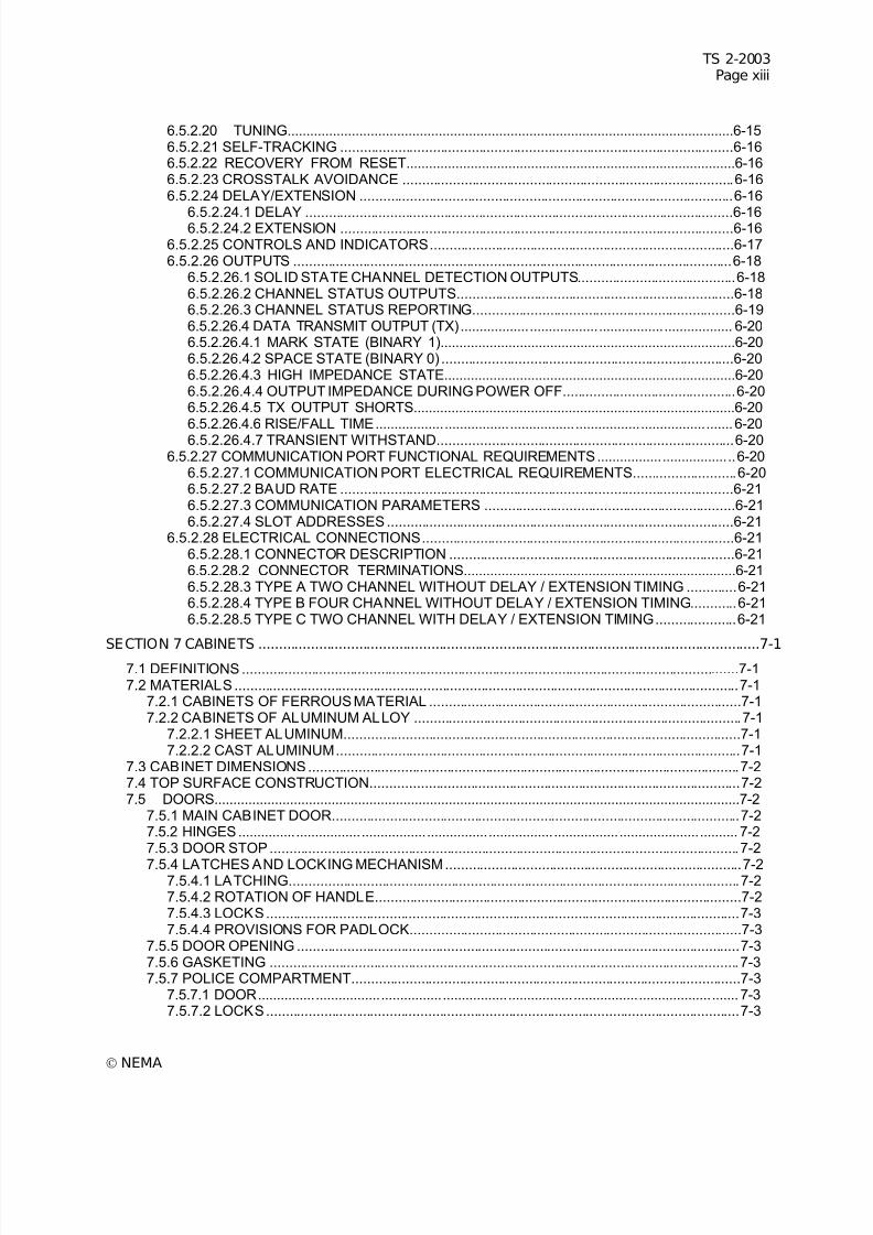
7/30/2019 NEMA TS2-2003- Traffic Controller Assemb
http://slidepdf.com/reader/full/nema-ts2-2003-traffic-controller-assemb 15/246
TS 2-2003Page xiii
© NEMA
6.5.2.20 TUNING......................................................................................................................6-156.5.2.21 SELF-TRACKING ......................................................................................................6-166.5.2.22 RECOVERY FROM RESET.......................................................................................6-166.5.2.23 CROSSTALK AVOIDANCE ......................................................................................6-166.5.2.24 DELAY/EXTENSION .................................................................................................6-16
6.5.2.24.1 DELAY ...............................................................................................................6-166.5.2.24.2 EXTENSION ......................................................................................................6-166.5.2.25 CONTROLS AND INDICATORS...............................................................................6-176.5.2.26 OUTPUTS ..................................................................................................................6-18
6.5.2.26.1 SOLID STATE CHANNEL DETECTION OUTPUTS.........................................6-186.5.2.26.2 CHANNEL STATUS OUTPUTS........................................................................6-186.5.2.26.3 CHANNEL STATUS REPORTING....................................................................6-196.5.2.26.4 DATA TRANSMIT OUTPUT (TX)....................................................................... 6-206.5.2.26.4.1 MARK STATE (BINARY 1)..............................................................................6-206.5.2.26.4.2 SPACE STATE (BINARY 0) ............................................................................6-206.5.2.26.4.3 HIGH IMPEDANCE STATE.............................................................................6-206.5.2.26.4.4 OUTPUT IMPEDANCE DURING POWER OFF.............................................6-206.5.2.26.4.5 TX OUTPUT SHORTS.....................................................................................6-206.5.2.26.4.6 RISE/FALL TIME............................................................................................. 6-206.5.2.26.4.7 TRANSIENT WITHSTAND.............................................................................6-20
6.5.2.27 COMMUNICATION PORT FUNCTIONAL REQUIREMENTS....................................6-206.5.2.27.1 COMMUNICATION PORT ELECTRICAL REQUIREMENTS...........................6-206.5.2.27.2 BAUD RATE ......................................................................................................6-216.5.2.27.3 COMMUNICATION PARAMETERS .................................................................6-216.5.2.27.4 SLOT ADDRESSES..........................................................................................6-21
6.5.2.28 ELECTRICAL CONNECTIONS.................................................................................6-216.5.2.28.1 CONNECTOR DESCRIPTION ..........................................................................6-216.5.2.28.2 CONNECTOR TERMINATIONS........................................................................6-216.5.2.28.3 TYPE A TWO CHANNEL WITHOUT DELAY / EXTENSION TIMING .............6-216.5.2.28.4 TYPE B FOUR CHANNEL WITHOUT DELAY / EXTENSION TIMING............6-216.5.2.28.5 TYPE C TWO CHANNEL WITH DELAY / EXTENSION TIMING.....................6-21
SECTION 7 CABINETS .............................................................................................................................7-17.1 DEFINITIONS .................................................................................................................................7-17.2 MATERIALS ...................................................................................................................................7-1
7.2.1 CABINETS OF FERROUS MATERIAL .................................................................................7-17.2.2 CABINETS OF ALUMINUM ALLOY .....................................................................................7-1
7.2.2.1 SHEET ALUMINUM.......................................................................................................7-17.2.2.2 CAST ALUMINUM.........................................................................................................7-1
7.3 CABINET DIMENSIONS................................................................................................................7-27.4 TOP SURFACE CONSTRUCTION................................................................................................7-27.5 DOORS...........................................................................................................................................7-2
7.5.1 MAIN CABINET DOOR..........................................................................................................7-27.5.2 HINGES.................................................................................................................................. 7-27.5.3 DOOR STOP..........................................................................................................................7-2
7.5.4 LATCHES AND LOCKING MECHANISM.............................................................................7-27.5.4.1 LATCHING.....................................................................................................................7-27.5.4.2 ROTATION OF HANDLE...............................................................................................7-27.5.4.3 LOCKS...........................................................................................................................7-37.5.4.4 PROVISIONS FOR PADLOCK......................................................................................7-3
7.5.5 DOOR OPENING ...................................................................................................................7-37.5.6 GASKETING ..........................................................................................................................7-37.5.7 POLICE COMPARTMENT.....................................................................................................7-3
7.5.7.1 DOOR............................................................................................................................. 7-37.5.7.2 LOCKS...........................................................................................................................7-3
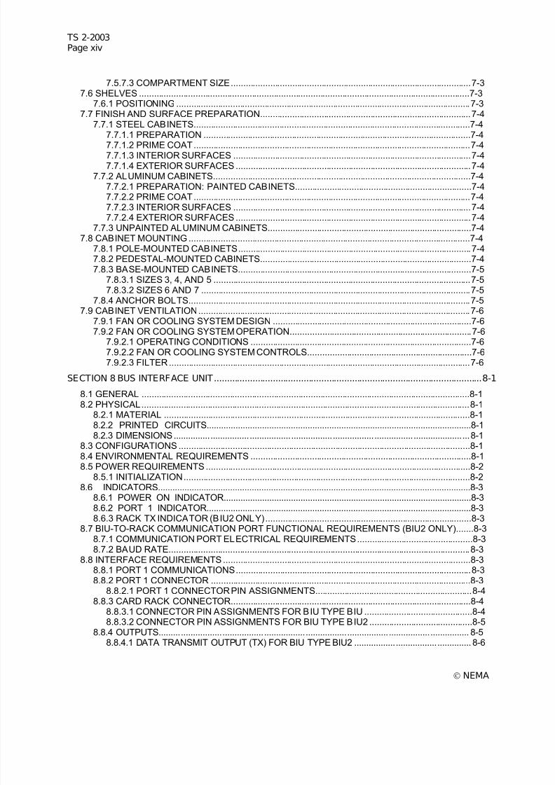
7/30/2019 NEMA TS2-2003- Traffic Controller Assemb
http://slidepdf.com/reader/full/nema-ts2-2003-traffic-controller-assemb 16/246
TS 2-2003Page xiv
© NEMA
7.5.7.3 COMPARTMENT SIZE..................................................................................................7-37.6 SHELVES .......................................................................................................................................7-3
7.6.1 POSITIONING ........................................................................................................................7-37.7 FINISH AND SURFACE PREPARATION......................................................................................7-4
7.7.1 STEEL CABINETS.................................................................................................................7-4
7.7.1.1 PREPARATION .............................................................................................................7-47.7.1.2 PRIME COAT.................................................................................................................7-47.7.1.3 INTERIOR SURFACES .................................................................................................7-47.7.1.4 EXTERIOR SURFACES ................................................................................................7-4
7.7.2 ALUMINUM CABINETS.........................................................................................................7-47.7.2.1 PREPARATION: PAINTED CABINETS........................................................................7-47.7.2.2 PRIME COAT.................................................................................................................7-47.7.2.3 INTERIOR SURFACES .................................................................................................7-47.7.2.4 EXTERIOR SURFACES ................................................................................................7-4
7.7.3 UNPAINTED ALUMINUM CABINETS...................................................................................7-47.8 CABINET MOUNTING ...................................................................................................................7-4
7.8.1 POLE-MOUNTED CABINETS...............................................................................................7-47.8.2 PEDESTAL-MOUNTED CABINETS......................................................................................7-47.8.3 BASE-MOUNTED CABINETS...............................................................................................7-5
7.8.3.1 SIZES 3, 4, AND 5 .........................................................................................................7-57.8.3.2 SIZES 6 AND 7 ..............................................................................................................7-5
7.8.4 ANCHOR BOLTS...................................................................................................................7-57.9 CABINET VENTILATION...............................................................................................................7-6
7.9.1 FAN OR COOLING SYSTEM DESIGN .................................................................................7-67.9.2 FAN OR COOLING SYSTEM OPERATION..........................................................................7-6
7.9.2.1 OPERATING CONDITIONS ..........................................................................................7-67.9.2.2 FAN OR COOLING SYSTEM CONTROLS...................................................................7-67.9.2.3 FILTER...........................................................................................................................7-6
SECTION 8 BUS INTERFACE UNIT.........................................................................................................8-1
8.1 GENERAL ......................................................................................................................................8-18.2 PHYSICAL......................................................................................................................................8-1
8.2.1 MATERIAL .............................................................................................................................8-18.2.2 PRINTED CIRCUITS..............................................................................................................8-18.2.3 DIMENSIONS.........................................................................................................................8-1
8.3 CONFIGURATIONS .......................................................................................................................8-18.4 ENVIRONMENTAL REQUIREMENTS ..........................................................................................8-18.5 POWER REQUIREMENTS ............................................................................................................8-2
8.5.1 INITIALIZATION.....................................................................................................................8-28.6 INDICATORS..................................................................................................................................8-3
8.6.1 POWER ON INDICATOR.......................................................................................................8-38.6.2 PORT 1 INDICATOR..............................................................................................................8-38.6.3 RACK TX INDICATOR (BIU2 ONLY)....................................................................................8-3
8.7 BIU-TO-RACK COMMUNICATION PORT FUNCTIONAL REQUIREMENTS (BIU2 ONLY).......8-38.7.1 COMMUNICATION PORT ELECTRICAL REQUIREMENTS...............................................8-3
8.7.2 BAUD RATE...........................................................................................................................8-38.8 INTERFACE REQUIREMENTS .....................................................................................................8-3
8.8.1 PORT 1 COMMUNICATIONS................................................................................................8-38.8.2 PORT 1 CONNECTOR ..........................................................................................................8-3
8.8.2.1 PORT 1 CONNECTOR PIN ASSIGNMENTS................................................................8-48.8.3 CARD RACK CONNECTOR..................................................................................................8-4
8.8.3.1 CONNECTOR PIN ASSIGNMENTS FOR BIU TYPE BIU ............................................8-48.8.3.2 CONNECTOR PIN ASSIGNMENTS FOR BIU TYPE BIU2 ..........................................8-5
8.8.4 OUTPUTS............................................................................................................................... 8-58.8.4.1 DATA TRANSMIT OUTPUT (TX) FOR BIU TYPE BIU2 ................................................ 8-6
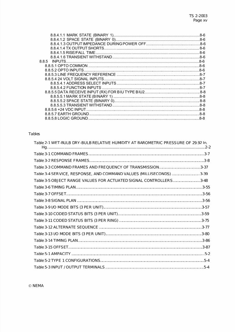
7/30/2019 NEMA TS2-2003- Traffic Controller Assemb
http://slidepdf.com/reader/full/nema-ts2-2003-traffic-controller-assemb 17/246
TS 2-2003Page xv
© NEMA
8.8.4.1.1 MARK STATE (BINARY 1).....................................................................................8-68.8.4.1.2 SPACE STATE (BINARY 0)...................................................................................8-68.8.4.1.3 OUTPUT IMPEDANCE DURING POWER OFF....................................................8-68.8.4.1.4 TX OUTPUT SHORTS............................................................................................ 8-68.8.4.1.5 RISE/FALL TIME.................................................................................................... 8-6
8.8.4.1.6 TRANSIENT WITHSTAND....................................................................................8-68.8.5 INPUTS...................................................................................................................................8-68.8.5.1 OPTO COMMON ...........................................................................................................8-68.8.5.2 OPTO INPUTS...............................................................................................................8-68.8.5.3 LINE FREQUENCY REFERENCE ................................................................................8-78.8.5.4 24 VOLT SIGNAL INPUTS............................................................................................8-7
8.8.5.4.1 ADDRESS SELECT INPUTS................................................................................8-78.8.5.4.2 FUNCTION INPUTS ..............................................................................................8-7
8.8.5.5 DATA RECEIVE INPUT (RX) FOR BIU TYPE BIU2.....................................................8-88.8.5.5.1 MARK STATE (BINARY 1) ...................................................................................8-88.8.5.5.2 SPACE STATE (BINARY 0)..................................................................................8-88.8.5.5.3 TRANSIENT WITHSTAND....................................................................................8-8
8.8.5.6 +24 VDC INPUT.............................................................................................................8-88.8.5.7 EARTH GROUND..........................................................................................................8-88.8.5.8 LOGIC GROUND...........................................................................................................8-8
Tables
Table 2-1 WET-BULB DRY-BULB RELATIVE HUMIDITY AT BAROMETRIC PRESSURE OF 29.92 In.Hg..................................................................................................................................................2-2
Table 3-1 COMMAND FRAMES...........................................................................................................3-7
Table 3-2 RESPONSE FRAMES..........................................................................................................3-8
Table 3-3 COMMAND FRAMES AND FREQUENCY OF TRANSMISSION......................................3-37
Table 3-4 SERVICE, RESPONSE, AND COMMAND VALUES (MILLISECONDS) ..........................3-39 Table 3-5 OBJ ECT RANGE VALUES FOR ACTUATED SIGNAL CONTROLLERS.........................3-48
Table 3-6 TIMING PLAN.....................................................................................................................3-55
Table 3-7 OFFSET..............................................................................................................................3-56
Table 3-8 SIGNAL PLAN ....................................................................................................................3-56
Table 3-9 I/O MODE BITS (3 PER UNIT)...........................................................................................3-57
Table 3-10 CODED STATUS BITS (3 PER UNIT).............................................................................3-59
Table 3-11 CODED STATUS BITS (3 PER RING) ............................................................................3-75
Table 3-12 ALTERNATE SEQUENCE ...............................................................................................3-77
Table 3-13 I/O MODE BITS (3 PER UNIT).........................................................................................3-80
Table 3-14 TIMING PLAN...................................................................................................................3-86
Table 3-15 OFFSET............................................................................................................................3-87
Table 5-1 AMPACITY ...........................................................................................................................5-2
Table 5-2 TYPE 1 CONFIGURATIONS................................................................................................5-4
Table 5-3 INPUT / OUTPUT TERMINALS ...........................................................................................5-4
7/30/2019 NEMA TS2-2003- Traffic Controller Assemb
http://slidepdf.com/reader/full/nema-ts2-2003-traffic-controller-assemb 18/246
TS 2-2003Page xvi
© NEMA
Table 5-4 BIU ADDRESS ASSIGNMENT ............................................................................................5-9
Table 5-5 BIU 1 SIGNAL ASSIGNMENT..............................................................................................5-9
Table 5-6 BIU 2 SIGNAL ASSIGNMENT............................................................................................5-10
Table 5-7 BIU 3 SIGNAL ASSIGNMENT............................................................................................5-12
Table 5-8 BIU 4 SIGNAL ASSIGNMENT............................................................................................5-13
Table 5-9 DETECTOR RACK CONFIGURATIONS...........................................................................5-15
Table 5-10 DETECTOR MODULE COMMUNICATIONS ADDRESS ................................................5-16
Table 5-11 DETECTOR RACK BIU ADDRESS ASSIGNMENT ........................................................5-17
Table 5-12 BIU 9 SIGNAL ASSIGNMENT..........................................................................................5-17
Table 5-13 FIELD TERMINALS..........................................................................................................5-20
Table 5-14 MMU CHANNEL ASSIGNMENTS....................................................................................5-26
Table 6-1 DETECTOR UNIT TYPES....................................................................................................6-9
Table 6-2 CONNECTOR TERMINATIONS ........................................................................................6-22 Table 7-1 OUTLINE DIMENSIONS ......................................................................................................7-2
Table 8-1 BIU TYPES ...........................................................................................................................8-1
Figures
Figure 2-1 TEST PROFILE ...................................................................................................................2-7
Figure 2-2 SHOCK TEST FIXTURE ...................................................................................................2-12
Figure 2-3 PIV AND DV/DT TEST CIRCUIT (SOLID STATE LOAD SWITCH OR FLASHER) .........2-18
Figure 2-4 TEST CONFIGURATIONS................................................................................................2-20Figure 2-5 LOOP INPUT TERMINAL TRANSIENT TESTS ...............................................................2-22
Figure 3-1 PORT 1 CONNECTIONS, TYPE 1 CONTROLLER ASSEMBLY .......................................3-4
Figure 3-2 PORT 1 CONNECTIONS, TYPE 2 CONTROLLER ASSEMBLY .......................................3-4
Figure 3-3 PORT 1 TIMING..................................................................................................................3-5
Figure 3-4 PORT 1 FRAME FORMAT..................................................................................................3-5
Figure 3-5 COMMAND AND RESPONSE FRAME TIMING ..............................................................3-38
Figure 3-6 DUAL RING CONTROLLER UNIT....................................................................................3-61
Figure 3-7 SINGLE RING CONTROLLER UNIT ................................................................................3-62
Figure 3-8 VARIABLE INITIAL TIMING ..............................................................................................3-67
Figure 3-9 GAP REDUCTION ............................................................................................................3-68
Figure 3-10 ACTIVATED PHASE OPERATING IN THE NONACTIVATED MODE...........................3-69
Figure 3-11 ACTIVATED PHASE OPERATING IN THE NONACTIVATED MODE...........................3-71
Figure 3-12 LOAD SWITCH DRIVERS, PEDESTRIAN .....................................................................3-74
Figure 4-1 PROGRAMMING CARD.....................................................................................................4-9
7/30/2019 NEMA TS2-2003- Traffic Controller Assemb
http://slidepdf.com/reader/full/nema-ts2-2003-traffic-controller-assemb 19/246
TS 2-2003Page xvii
© NEMA
Figure 5-1 LOAD SWITCH OR FLASHER SUPPORT .........................................................................5-5
Figure 5-2 FRONT VIEW—LOAD SWITCH SUPPORT DIMENSIONS...............................................5-6
Figure 5-3 FRONT VIEW—FLASHER SUPPORT DIMENSIONS .......................................................5-7
Figure 5-4 CABINET POWER DISTRIBUTION SCHEMATIC ...........................................................5-23
Figure 5-5 TERMINAL & FACILITIES WIRING ..................................................................................5-27
Figure 6-1 CONNECTOR PIN ASSIGNMENT .....................................................................................6-2
Figure 6-2 CONNECTOR PIN ASSIGNMENTS SOLID STATE FLASHER (VIEWED—CONNECTOREND)..............................................................................................................................................6-5
Figure 6-3 FLASH TRANSFER RELAY WIRING DIAGRAM ...............................................................6-7
Figure 6-4 TWO CHANNEL CARD RACK UNIT ................................................................................6-10
Figure 6-5 FOUR CHANNEL CARD RACK UNIT ..............................................................................6-11
Figure 6-6 TEST LOOP CONFIGURATIONS.....................................................................................6-14
Figure 6-7 DELAY OPERATION ........................................................................................................6-17
Figure 6-8 EXTENSION OPERATION ...............................................................................................6-17
Figure 7-1 FOUNDATION FOR SIZES 3, 4, AND 5 BASE-MOUNTED CABINETS............................7-5
Figure 7-2 FOUNDATION FOR SIZE 6 AND 7 BASE-MOUNTED CABINETS ...................................7-6
Figure 8-1 BUS INTERFACE UNIT ......................................................................................................8-2

7/30/2019 NEMA TS2-2003- Traffic Controller Assemb
http://slidepdf.com/reader/full/nema-ts2-2003-traffic-controller-assemb 20/246
TS 2-2003Page xviii
© NEMA
Foreword
This NEMA Standards Publication TS 2-2003, Traffic Controller Assemblies, has been developed as adesign guide for traffic signaling equipment which can be safely installed and provide operational featuresnot covered by the NEMA TS 1-1989, Traffic Control Systems. Within the standard, any reference to aspecific manufacturer is made strictly for the purpose of defining interchangeability where there exists nonationally recognized standard covering all the requirements. The manufacturer references do notconstitute a preference.
The TS 2 Standards Publication has been established to reduce hazards to persons and property whentraffic signaling equipment is properly selected and installed in conformance with the requirements herein.
The user's attention is called to the possibility that compliance with this standard may require use of aninvention covered by patent rights. By publication of this standard, no position is taken with respect to thevalidity of this claim or of any patent rights in connection therewith.
Comments and suggestions for the improvement of this document are encouraged. They should be sentto:
Vice President, Engineering DepartmentNational Electrical Manufacturers Association
1300 N.17th StreetRosslyn, Virginia 22209
tel: (703) 841-3200fax: (703) 841-3300

7/30/2019 NEMA TS2-2003- Traffic Controller Assemb
http://slidepdf.com/reader/full/nema-ts2-2003-traffic-controller-assemb 21/246
TS 2-2003Page xix
© NEMA
Scope
This Standards Publication covers traffic signaling equipment used to facilitate and expedite the safemovement of pedestrians and vehicular traffic.
Two approaches to expansion of traffic features of NEMA TS 1, Traffic Control Systems are provided:
Type 1—
° Entirely new performance oriented standard.
Type 2—
° Use of the MSA, B, and C connectors in common use with NEMA TS 1 equipment.
The Type 1 approach embraces:
° Controller Unit
• Display-alphanumeric Display—32 Characters, 2 Lines Minimum
• Port 1 Connector
• High speed full duplex data channel connecting controller unit, conflict monitor(malfunction management unit), rear panel (terminals and facilities) and detectors.
• All data exchange with rear panel.
• Controller unit and conflict monitor exchange information on a regular basis,performing redundant checks on each other. Controller unit has access to all conflictmonitor internal information, making enhanced event logging, remote intersection
monitoring, and remote diagnostics feasible.
• All detector information, including detector diagnostics.
• ElA-485 serial communications interface with noise immunity characteristics.
• SDLC (synchronous data link) communication protocol with a bit rate of 153, 600bits/second, utilizing sophisticated error checking.
• Vast reduction in number of wires in the cabinet.
• Port 2 Connector
• Interface to personal computer.
• Interface to printer.
• Port 3 Connector
• 1200 baud, FSK serial port for on-street communications.
7/30/2019 NEMA TS2-2003- Traffic Controller Assemb
http://slidepdf.com/reader/full/nema-ts2-2003-traffic-controller-assemb 22/246
TS 2-2003Page xx
© NEMA
• Standard Features
• Actuated control.
• Conditional service.
• Additional detectors.
• Delay/extension/switching detectors.
• Dual entry.
• Alternate phase sequences.
• Start-up flash.
• Automatic flash.
• Dimming.
• Coordination: 16 timing plans; one cycle length per timing plan; one split per timingplan; three offset per timing plan.
• Preemption: six inputs; six sequences.
• Time base: yearly clock; daylight savings; leap year.
• Internal diagnostics: memory diagnostics; processor monitoring; conflict monitoringchecking; detector diagnostics.
° Conflict Monitor (Malfunction Management Unit)
• Single Type —configurable as 12 four-input channels or 16 three-input channels
• Port 1 Connector
• Communications with controller unit, as described above.
• MSA, MSB connectors downward compatible with those on a TS 1 conflict monitor;used primarily for sensing of voltages on field terminals.
• Low voltage monitoring—monitor will be the first unit in a cabinet to sense a lowvoltage condition and will put intersection in flash in an orderly manner. Thissequence will be reversed on power up.
• Detectors
• Rack mounted, 16 detector channels per rack, up to four racks.
• Port 1 connector: pluggable, interchangeable Bus Interface unit to convert Port 1 highspeed serial data to format required by individual detectors.
• Communications with controller unit, as described above.
• Per channel diagnostic data: open loop; shorted loop; excessive inductance change;watchdog failure.
• Detector reset capability.
• Operation from either 12 volt or 24 volt DC power supply.
7/30/2019 NEMA TS2-2003- Traffic Controller Assemb
http://slidepdf.com/reader/full/nema-ts2-2003-traffic-controller-assemb 23/246
TS 2-2003Page xxi
© NEMA
° Rear Panel (Terminals and Facilities)
• Conventional load switches, flasher, flash transfer relays.
• Termination points for needed functions.
• Port 1 connector: communications with controller unit, as described above, andpluggable, interchangeable Bus Interface Unit to convert Port 1 high speed serialdata to format required by rear panel.
The TS 2 Type 2 is the same as the Type 1 with the following exceptions:
° The MSA, MSB, and MSC connectors for the Controller Unit are compatible with equipmentconforming with the NEMA TS 1-1989 Standards Publication.
° MS connector pin-outs are configurable to one of eight modes to satisfy different applications andachieve different functionality. Default mode is pin compatible with TS 1-1989.
7/30/2019 NEMA TS2-2003- Traffic Controller Assemb
http://slidepdf.com/reader/full/nema-ts2-2003-traffic-controller-assemb 24/246
TS 2-2003Page xxii
© NEMA
HISTORY
This Standards Publication is predicated upon an industry perceived need to overcome limitations of theNEMA Standards Publication TS 1, Traffic Control Systems, which in 1976 reflected the first industrydocumentation of technically adequate and safe traffic control equipment.
The NEMA TS 1 as subsequently revised and expanded and re-affirmed in 1989:
1. Defined effective actuated intersection control.
2. As a complete package defined all equipment within the cabinet and test procedures.
3. Provided equipment interchangeability between manufacturers.
4. As a minimum functional standard facilitated design innovations.
Limitations inherent in NEMA TS 1 were seen as follows:
1. Reliance on point-to-point wire connection for all functions with termination points for all wires, manyof which are not utilized.
a. Numerous connections increase failure potential.
b. Not cost effective.
c. Hardware limited expandability.
2. Out-of-date technology.
3. Lack of uniformity in the implementation of the following functions and the resulting loss in equipmentinterchangeability:
a. Coordination.
b. Time base control.
c. Preemption.
d. Uniform Code flash.
e. Communications.
f. Diagnostics.
g. User interface.
The following industry guidelines were established to overcome the limitations in the NEMA TS 1Standards Publication:
1. Equipment requirements based on valid engineering concepts.
2. Interchangeability, performance oriented, without precluding downward compatibility with TS 1
equipment.
3. Emphasis on use of enhanced diagnostic techniques.
4. Minimize potential for malfunctions.
5. Provide for future expandability.
6. Enhanced user interface.
7/30/2019 NEMA TS2-2003- Traffic Controller Assemb
http://slidepdf.com/reader/full/nema-ts2-2003-traffic-controller-assemb 25/246
TS 2-2003Page xxiii
© NEMA
Four basic proposals were considered over a four-year period. These were:
1. Standardize the functions being provided on the MSD connector.
2. Free up seldom used pins on the MSA, MSB, and MSC connectors and reassign them to neededfunctions.
3. Develop an entirely new, performance oriented standard.
4. Proceed with Proposal 1, then move on to Proposal 3 for a long-term solution.
During the investigations, involving debate within the industry and inputs received from traffic engineersand those responsible for the selection, installation and maintenance of traffic control equipment actionswere taken on each proposal.
Industry debate of which approach to follow consumed approximately 2.5 years before approval of Proposal 3—proceed with the development of an entirely new, performance oriented standard. While themajority of the industry tended to favor this proposal, some members in opposition had concerns, many of which were valid, and each was carefully studied and evaluated, including joint consultations withdelegations from the Institute of Transportation Engineers (ITE) and the International Municipal SignalAssociation (IMSA), as well as at NEMA sponsored open forums at Annual Meetings of ITE.
The advantages of a new performance oriented standard were identified as:
1. Communication between major equipment within the cabinet over a data channel with virtuallyunlimited capacity. Potential for future expandability is thereby maximized.
2. Use of a high speed data channel between the controller unit, malfunction management unit,detectors, and rear panel reduces the number of connections and facilitates diagnostic testing,thereby reducing the potential for malfunction.
3. Cost effectiveness of communications protocols.
4. Enhanced user interface.
During the development of the new NEMA Standards Publication TS 2 two approaches evolved:
1. Type 1, which utilizes a high speed data channel between all major equipment to maximize thefunctionality and expandability.
2. Type 2, which retains the MSA, MSB, and MSC connectors for data exchange with the rear panel,providing a degree of downward compatibility.

7/30/2019 NEMA TS2-2003- Traffic Controller Assemb
http://slidepdf.com/reader/full/nema-ts2-2003-traffic-controller-assemb 26/246
7/30/2019 NEMA TS2-2003- Traffic Controller Assemb
http://slidepdf.com/reader/full/nema-ts2-2003-traffic-controller-assemb 27/246
TS 2-2003Page xxv
© NEMA
TS 2-2003 UPDATE
The following is a summary of the changes provided by the 2003 release of this Standards Publication:
SECTION 3:
Page 3-19 : Clause 3.3.1.4.2.2 Type 129 MMU Inputs/Status (Type 1 ACK) - revisedPage 3-93 : Clause 3.9.3.1.3 Port 1 - revised
SECTION 5:
Page 5-14 : Clause 5.3.3 Port 1 Communication Cables - revisedPage 5-22 : Clause 5.4.2.1 Grounding System - revised
SECTION 6:
Page 6-22 : Table 6-2CONNECTOR TERMINATIONS - revised
SECTION 8:
Page 8-2 : Clause 8.5 POWER REQUIREMENTS - revisedPage 8-2 : Clause 8.5.1 Initialization - revisedPage 8-3 : Clause 8.7.1 Communication Port Electrical Requirements - revisedPage 8-5 : Clause 8.8.4 Outputs - revisedPage 8-6 : Clause 8.8.4.1.4 TX Output Shorts - revisedPage 8-6 : Clause 8.8.5.2 Opto Inputs - revisedPage 8-7 : Clause 8.8.5.4 24 Volt Signal Inputs - revisedPage 8-7 : Clause 8.8.5.4.2 Function Inputs - revisedPage 8-8 : Clause 8.8.5.5 Data Receive Input (RX) for BIU Type BIU2 - revised
Paragraphs revised in this update are denoted by a wavy line to the right of the paragraph as shown for
this paragraph.

7/30/2019 NEMA TS2-2003- Traffic Controller Assemb
http://slidepdf.com/reader/full/nema-ts2-2003-traffic-controller-assemb 28/246
7/30/2019 NEMA TS2-2003- Traffic Controller Assemb
http://slidepdf.com/reader/full/nema-ts2-2003-traffic-controller-assemb 29/246
TS 2-2003Page 1-1
© NEMA
SECTION 1DEFINITIONS
These definitions reflect the consensus of the traffic control equipment industry as represented by NEMAand are intended to be in harmony with terminology in current usage, such as is published in the "Manualon Uniform Traffic Control Devices” and various technical reports of the Institute of TransportationEngineers, 525 School Street, S.W., Washington, D.C. 20024.
1.1 CONTROL EQUIPMENT
The abbreviations used in this Standard Publication are defined as follows:
AC – Alternating CurrentBIU – Bus Interface UnitCA – Controller Assembly
CU – Controller UnitDR – Detector RackMMU – Malfunction Management Unit TF – Terminals and Facilities
1.1.1 Auxiliary Equipment
Separate devices used to add supplementary features to a controller assembly.
1.1.2 Barrier
See 3.5.1.2.
1.1.3 Cabinet
An outdoor enclosure for housing the controller unit and associated equipment.
1.1.4 Call
A registration of a demand for right-of-way by traffic (vehicles or pedestrians) to a controller unit.
1.1.4.1 Serviceable Conflic ting Call
A call which:
1. Occurs on a conflicting phase not having the right-of-way at the time the call is placed.
2. Occurs on a conflicting phase which is capable of responding to a call.
3. When occurring on a conflicting phase operating in an occupancy mode, remains present until givenits right-of-way.
1.1.5 Check
An output from a controller unit that indicates the existence of unanswered call(s).1.1.6 Connector
A device enabling outgoing and incoming electrical circuits to be connected and disconnected without thenecessity of installing and removing individual wires leading from the control unit.
1.1.6.1 Not Used Connect ions
The Not Used connector pin terminations are used exclusively to prevent interchangeability with unitsalready in use not in conformance to this publication. These connector pins are not to be internallyconnected.

7/30/2019 NEMA TS2-2003- Traffic Controller Assemb
http://slidepdf.com/reader/full/nema-ts2-2003-traffic-controller-assemb 30/246
7/30/2019 NEMA TS2-2003- Traffic Controller Assemb
http://slidepdf.com/reader/full/nema-ts2-2003-traffic-controller-assemb 31/246
TS 2-2003Page 1-3
© NEMA
1.1.7.10 Semi-Traffic-Actuated Control ler Assembly
A type of traffic-actuated controller assembly in which means are provided for traffic actuation on one ormore but not all approaches to the intersection.
1.1.7.11 Traffic-Actuated Controller Assembly
A controller assembly for supervising the operation of traffic control signals in accordance with the varyingdemands of traffic as registered with the controller by detectors.
1.1.8 Controller Uni t
A controller unit is that portion of a controller assembly that is devoted to the selection and timing of signaldisplays.
1.1.8.1 Digital Cont roller Unit
A controller unit wherein timing is based upon a defined frequency source such as a 60-hertz alternatingcurrent source. (See 1.1.49.3.)
1.1.8.2 Multi-Ring Controller Unit
See 3.5.1.3.
1.1.8.3 Single-Ring Controller Unit
See 3.5.1.4.
1.1.9 Coordination
The control of controller units in a manner to provide a relationship between specific green indications atadjacent intersections in accordance with a time schedule to permit continuous operation of groups of vehicles along the street at a planned speed. (See 1.1.30.)
1.1.10 Coordinator
A device or program/routine which provides coordination.
1.1.11 Cycle
The total time to complete one sequence of signalization around an intersection.
In an actuated controller unit, a complete cycle is dependent on the presence of calls on all phases. In apretimed controller unit, it is a complete sequence of signal indications.
1.1.11.1 Cycle Length
The time period in seconds required for one complete cycle.
1.1.12 Density
A measure of the concentration of vehicles, stated as the number of vehicles per mile per lane.
1.1.13 Detector
See 1.2.5.
1.1.14 Device
1.1.14.1 Electromechanical Device
A device which is characterized by electrical circuits utilizing relays, step switches, motors, etc.
1.1.14.2 Electronic Device
A device which is characterized by electrical circuits utilizing resistors, capacitors, and inductors, whichmay include electromechanical and solid-state devices.

7/30/2019 NEMA TS2-2003- Traffic Controller Assemb
http://slidepdf.com/reader/full/nema-ts2-2003-traffic-controller-assemb 32/246
TS 2-2003Page 1-4
© NEMA
1.1.14.3 Solid-State Device
A device which is characterized by electrical circuits, the active components of which are semi-conductors, to the exclusion of electromechanical devices or tubes.
1.1.15 Dial
The cycle timing reference or coordination input activating same. Dial is also frequently used to describethe cycle.
1.1.16 Dwel l
See 1.1.42.
1.1.17 Extension, Unit
The timing interval during the extensible portion which is resettable by each detector actuation. The greeninterval of the phase may terminate on expiration of the unit extension time.
1.1.18 Entry
1.1.18.1 Dual Entry
See 3.5.1.5.1.1.18.2 Single Entry
See 3.5.1.6.
1.1.19 Flasher
A device used to open and close signal circuits at a repetitive rate.
1.1.20 Force Off
A command to force the termination of the green interval. (See 3.4.5.2 and 3.5.4.1.)
1.1.21 Gap Reduction
A feature whereby the Unit Extension or allowed time spacing between successive vehicle actuations on
the phase displaying the green in the extensible portion of the interval is reduced.1.1.22 Hold
A command that retains the existing Green interval.
1.1.23 Interconnect
A means of remotely controlling some or all of the functions of a traffic signal.
1.1.24 Interval
The part or parts of the signal cycle during which signal indications do not change.
1.1.24.1 Minimum Green Interval
The shortest green time of a phase. If a time setting control is designated as Minimum Green, the greentime shall be not less than that setting.
1.1.24.2 Pedestrian Clearance Interval
The first clearance interval for the pedestrian signal following the pedestrian WALK indication.
1.1.24.3 Red Clearance Interval
A clearance interval which may follow the yellow change interval during which both the terminating phaseand the next phase display Red signal indications.
7/30/2019 NEMA TS2-2003- Traffic Controller Assemb
http://slidepdf.com/reader/full/nema-ts2-2003-traffic-controller-assemb 33/246
TS 2-2003Page 1-5
© NEMA
1.1.24.4 Sequence, Interval
The order of appearance of signal indications during successive intervals of a cycle.
1.1.24.5 Yellow Change Interval
The first interval following the green interval in which the signal indication for that phase is yellow.
1.1.25 Manual
1.1.25.1 Manual Operation
The operation of a controller assembly by means of a hand-operated device(s). A pushbutton is anexample of such a device.
1.1.25.2 Manual Pushbutton
An auxiliary device for hand operation of a controller assembly.
1.1.26 Maximum Green
The maximum green time with a serviceable opposing actuation, which may start during the initial portion.
1.1.27 Memory
1.1.27.1 Detector Memory
The retention of a call for future utilization by the controller assembly.
1.1.27.2 Nonlocking Memory
A mode of actuated-controller-unit operation which does not require detector memory.
1.1.27.3 Non-Volatile Memory
Read/Write memory that is capable of data retention during periods when AC power is not applied for aminimum period of 30 days.
1.1.27.4 Volatile Memory
Read/Write memory that loses data when power is removed.
1.1.27.5 Random Access Memory (RAM)
Semiconductor Read/Write volatile memory. Data is lost if power is turned off.
1.1.27.6 Read Only Memory (ROM)
Read-Only, non-volatile, semiconductor memory manufactured with data content, permanently stored.
1.1.27.7 Programmable Read Only Memory (PROM)
Read-Only, non-volatile, semiconductor memory that allows a program to reside permanently in a piece of hardware.
1.1.27.8 Programmable Read Only Memory (EPROM)
Read-Only, non-volatile, semiconductor memory that is erasable (via ultra-violet light) and
reprogrammable. (See 1.1.27.6 and 1.1.27.7).
1.1.28 Malfunction Management Unit
A device used to detect and respond to improper and conflicting signals and improper operating voltagesin a traffic control system.
1.1.29 Modular Design
A design concept such that functions are sectioned into units which can be readily exchanged with similarunits.
7/30/2019 NEMA TS2-2003- Traffic Controller Assemb
http://slidepdf.com/reader/full/nema-ts2-2003-traffic-controller-assemb 34/246
TS 2-2003Page 1-6
© NEMA
1.1.30 Offset
Offset is the time relationship, expressed in seconds or percent of cycle length, determined by thedifference between a defined point in the coordinated green and a system reference point.
1.1.31 Omit, Phase (Special Skip , Force Skip)
A command that causes omission of a selected phase.
1.1.32 Overlap
A Green indication that allows traffic movement during the green intervals of and clearance intervalsbetween two or more phases.
1.1.33 Passage Time
The time allowed for a vehicle to travel at a selected speed from the detector to the stop line.
1.1.34 Pattern
A unique set of coordination parameters (cycle value, split values, offset value, and sequence).
1.1.35 Phase
1.1.35.1 Traffic Phase
Those green, change, and clearance intervals in a cycle assigned to any independent movement(s) of traffic.
1.1.35.2 Conflic ting Phases
Conflicting phases are two or more traffic phases which will cause interfering traffic movements if operated concurrently.
1.1.35.3 Nonconflicting Phase
Non-conflicting phases are two or more traffic phases which will not cause interfering traffic movements if operated concurrently.
1.1.35.4 Pedestrian Phase
A traffic phase allocated to pedestrian traffic which may provide a right-of-way pedestrian indication eitherconcurrently with one or more vehicular phases, or to the exclusion of all vehicular phases.
1.1.35.5 Phase Sequence
A predetermined order in which the phases of a cycle occur.
1.1.35.6 Parent Phase
A traffic phase with which a subordinate phase is associated.
1.1.35.7 Vehicular Phase
A vehicular phase is a phase which is allocated to vehicular traffic movement as timed by the controllerunit.
1.1.36 Portion
1.1.36.1 Extensible Portion
That portion of the green interval of an actuated phase following the initial portion which may beextended, for example, by traffic actuation.
1.1.36.2 Initial Portion
The first timed portion of the green interval in an actuated controller unit:
1. Fixed Initial Portion: A preset initial portion that does not change.
7/30/2019 NEMA TS2-2003- Traffic Controller Assemb
http://slidepdf.com/reader/full/nema-ts2-2003-traffic-controller-assemb 35/246
TS 2-2003Page 1-7
© NEMA
2. Computed Initial Portion: An initial portion which is traffic adjusted.
3. Maximum Initial Portion: The limit of the computed initial portion.
4. Minimum Initial Portion: See Fixed Initial Portion.
5. Added Initial Portion: An increment of time added to the minimum initial portion in response to vehicleactuations.
1.1.36.3 Interval Portion
A discrete subdivision of an interval during which the signals do not change.
1.1.37 Preemption
The transfer of the normal control of signals to a special signal control mode for the purpose of servicingrailroad crossings, emergency vehicle passage, mass transit vehicle passage, and other special tasks,the control of which require terminating normal traffic control to provide the priority needs of the specialtask.
1.1.38 Preemptor, Traffic Control ler
A device or program/routine which provides preemption.
1.1.39 Preferred Sequence
See 3.5.1.8.
1.1.40 Progression
The act of various controller units providing specific green indications in accordance with a time scheduleto permit continuous operation of groups of vehicles along the street at a planned speed.
1.1.41 Red Indication, Minimum (Red Revert)
Provision within the controller unit to assure a minimumRed signal indication in a phase following theYellow Change interval of that phase.
1.1.42 Rest
The interval portion of a phase when present timing requirements have been completed.
1.1.43 Ring
See 3.5.1.1.
1.1.44 Spli t
The segment of the cycle length allocated to each phase or interval that may occur (expressed in percentor seconds).
In an actuated controller unit, split is the time in the cycle allocated to a phase.
In a pretimed controller unit, split is the time allocated to an interval.
1.1.45 Suppressors
1.1.45.1 Suppressor, Radio Interference
A device inserted in the power line in the controller assembly (cabinet) that reduces the radiointerference.
1.1.45.2 Suppressor, Transient
A device which serves to reduce transient over-voltages.
7/30/2019 NEMA TS2-2003- Traffic Controller Assemb
http://slidepdf.com/reader/full/nema-ts2-2003-traffic-controller-assemb 36/246
TS 2-2003Page 1-8
© NEMA
1.1.46 Switch
1.1.46.1 Auto/Manual Switch
A device which, when operated, discontinues normal signal operation and permits manual operation.
1.1.46.2 Flash Contro l Switch
A device which, when operated, discontinues normal signal operation and causes the flashing of anypredetermined combination of signal indications.
1.1.46.3 Power Line Switch (Disconnect Switch)
A manual switch for disconnecting power to the controller assembly and traffic control signals.
1.1.46.4 Recall Switch
A manual switch which causes the automatic return of the right-of-way to its associated phase.
1.1.46.5 Signal Load Switch
A device used to switch power to the signal lamps.
1.1.46.6 Signal Shut-Down Switch
A manual switch to discontinue the operation of traffic control signals without affecting the power supplyto other components in the controller cabinet.
1.1.47 Time Base Contro l
A means for the automatic selection of modes of operation of traffic signals in a manner prescribed by apredetermined time schedule.
1.1.48 Terminals, Field
Devices for connecting wires entering the controller assembly.
1.1.49 Timing
1.1.49.1 Analog Timing
Pertaining to a method of timing that measures continuous variables, such as voltage or current.
1.1.49.2 Concurrent Timing
A mode of controller unit operation whereby a traffic phase can be selected and timed simultaneously andindependently with another traffic phase.
1.1.49.3 Digital Timing
Pertaining to a method of timing that operates by counting discrete units.
1.1.49.4 Timing Plan
The Split times for all segments (Phase/Interval) of the coordination cycle.
1.1.50 Yield
A command which permits termination of the green interval. (See 1.1.22.)
1.2 DETECTORS
1.2.1 Actuation
The operation of any type of detector.
1.2.2 Antenna
The radiating or receiving elements utilized in transmitting or receiving electromagnetic waves.
7/30/2019 NEMA TS2-2003- Traffic Controller Assemb
http://slidepdf.com/reader/full/nema-ts2-2003-traffic-controller-assemb 37/246
TS 2-2003Page 1-9
© NEMA
1.2.3 Call
See 1.1.4.
1.2.4 Detection
1.2.4.1 Adviso ry Detection
The detection of vehicles on one or more intersection approaches solely for the purpose of modifying thephase sequence and/or length for other approaches to the intersection.
1.2.4.2 Passage Detection
The ability of a vehicle detector to detect the passage of a vehicle moving through the zone of detectionand to ignore the presence of a vehicle stopped within the zone of detection.
1.2.4.3 Presence Detection
The ability of a vehicle detector to sense that a vehicle, whether moving or stopped, has appeared in itszone of detection.
1.2.5 Detector
A device for indicating the presence or passage of vehicles or pedestrians.1.2.5.1 Bidirectional Detector
A detector that is capable of being actuated by vehicles proceeding in either of two directions and of indicating in which of the directions the vehicles were moving.
1.2.5.2 Calling Detector
A detector that is installed in a selected location to detect vehicles which may not otherwise be detectedand whose output may be modified by the controller unit.
1.2.5.3 Classification Detector
A detector that has the capability of differentiating among types of vehicles.
1.2.5.4 Directional Detector
A detector that is capable of being actuated only by vehicles proceeding in one specified direction.
1.2.5.5 Extension Detector
A detector that is arranged to register actuations at the controller unit only during the green interval forthat approach so as to extend the green time of the actuating vehicles.
1.2.5.6 Infrared Detector
A detector that senses radiation in the infrared spectrum.
1.2.5.7 Light-Sensitive Detector
A detector that utilizes a light-sensitive device for sensing the passage of an object interrupting a beam of light directed at the sensor.
1.2.5.8 Loop Detector
A detector that senses a change in inductance of its inductive loop sensor by the passage or presence of a vehicle near the sensor.
1.2.5.9 Magnetic Detector
A detector that senses changes in the earth's magnetic field caused by the movement of a vehicle near itssensor.
7/30/2019 NEMA TS2-2003- Traffic Controller Assemb
http://slidepdf.com/reader/full/nema-ts2-2003-traffic-controller-assemb 38/246
TS 2-2003Page 1-10
© NEMA
1.2.5.10 Magnetometer Detector
A detector that measures the difference in the level of the earth's magnetic forces caused by the passageor presence of a vehicle near its sensor.
1.2.5.11 Nondirect ional Detector
A detector that is capable of being actuated by vehicles proceeding in any direction.
1.2.5.12 Pedestrian Detector
A detector that is responsive to operation by or the presence of a pedestrian.
1.2.5.13 Pneumatic Detector
A pressure-sensitive detector that uses a pneumatic tube as a sensor.
1.2.5.14 Pressure-Sensiti ve Detector
A detector that is capable of sensing the pressure of a vehicle passing over the surface of its sensor.
1.2.5.15 Radar Detector
A detector that is capable of sensing the passage of a vehicle through its field of emitted microwave
energy.
1.2.5.16 System Detector
Any type of vehicle detector used to obtain representative traffic flow information.
1.2.5.17 Side-Fire Detector
A vehicle detector with its sensor located to one side of the roadway.
1.2.5.18 Sound-Sensitive Vehicle Detector
A detector that responds to sound waves generated by the passage of a vehicle near the surface of thesensor.
1.2.5.19 Ultrasonic Detector
A detector that is capable of sensing the passage or presence of a vehicle through its field of emittedultrasonic energy.
1.2.6 Detector Mode
A term used to describe the operation of a detector channel output when a presence detection occurs.
1. Pulse Mode: Detector produces a short output pulse when detection occurs.
2. Controlled Output: The ability of a detector to produce a pulse that has a predetermined durationregardless of the length of time a vehicle is in the zone of detection.
3. Continuous-Presence Mode: Detector output continues if any vehicle (first or last remaining) remainsin the zone of detection.
4. Limited-Presence Mode: Detector output continues for a limited period of time if vehicles remain in
zone of detection.1.2.7 Inductive Loop Detector System
See 6.5.1.5.
1.2.8 Inductive Loop Detector Unit
See 6.5.1.6.
7/30/2019 NEMA TS2-2003- Traffic Controller Assemb
http://slidepdf.com/reader/full/nema-ts2-2003-traffic-controller-assemb 39/246
TS 2-2003Page 1-11
© NEMA
1.2.9 Lead-in Cable
See 6.5.1.4.
1.2.10 Output
1.2.10.1 Extension Output
The ability of a detector to continue its output for a predetermined length of time after the vehicle has leftits zone of detection.
1.2.10.2 Delayed Output
The ability of a detector to delay its output for a predetermined length of time after a vehicle has enteredits zone of detection.
1.2.11 Probe
The sensor form that is commonly used with a magnetometer type detector.
1.2.12 Sensor
The sensing element of a detector.
1.2.13 Vehicle Detector System
See 6.5.1.10.
1.2.14 Zone of Detection (Sensing Zone)
That area of the roadway within which a vehicle will be detected by a vehicle detector system.
1.3 SIGNAL
A device which is electrically operated by a controller assembly and which communicates a prescribedaction (or actions) to traffic.
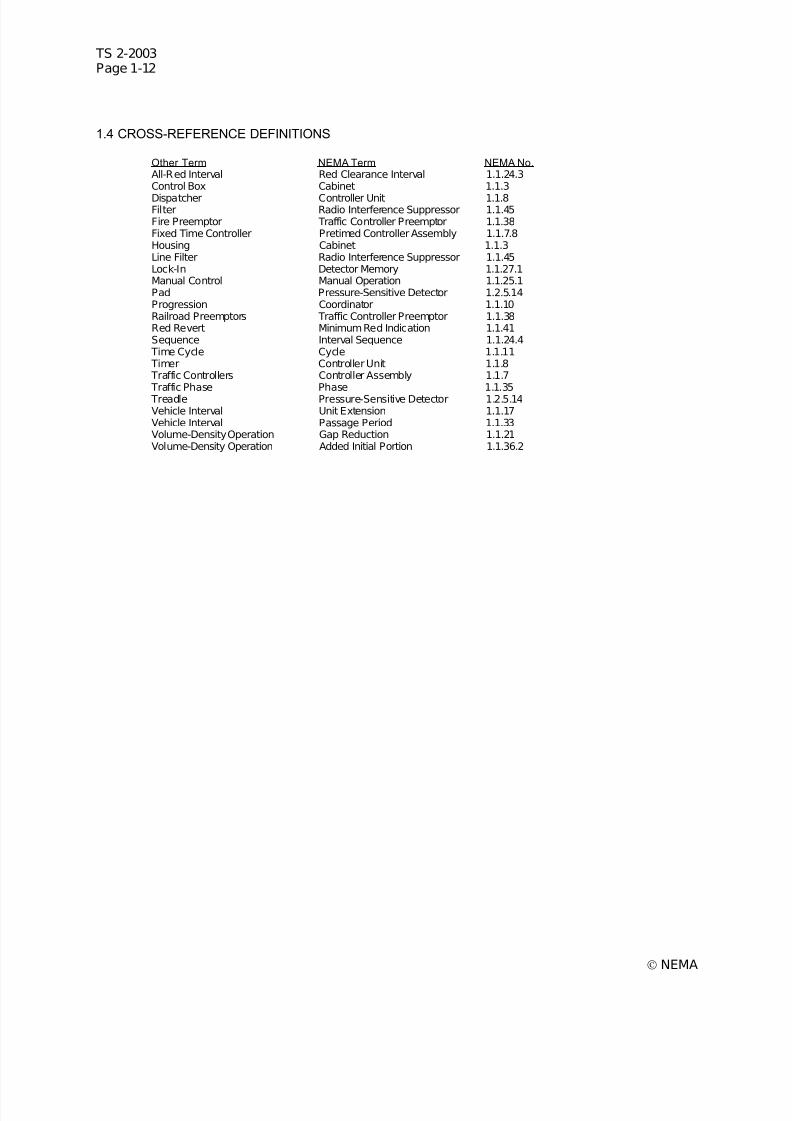
7/30/2019 NEMA TS2-2003- Traffic Controller Assemb
http://slidepdf.com/reader/full/nema-ts2-2003-traffic-controller-assemb 40/246
TS 2-2003Page 1-12
© NEMA
1.4 CROSS-REFERENCE DEFINITIONS
Other Term NEMA Term NEMA No.All-Red Interval Red Clearance Interval 1.1.24.3Control Box Cabinet 1.1.3
Dispatcher Controller Unit 1.1.8Filter Radio Interference Suppressor 1.1.45Fire Preemptor Traffic Controller Preemptor 1.1.38Fixed Time Controller Pretimed Controller Assembly 1.1.7.8Housing Cabinet 1.1.3Line Filter Radio Interference Suppressor 1.1.45Lock-In Detector Memory 1.1.27.1Manual Control Manual Operation 1.1.25.1Pad Pressure-Sensitive Detector 1.2.5.14Progression Coordinator 1.1.10Railroad Preemptors Traffic Controller Preemptor 1.1.38Red Revert Minimum Red Indication 1.1.41Sequence Interval Sequence 1.1.24.4
Time Cycle Cycle 1.1.11 Timer Controller Unit 1.1.8 Traffic Controllers Controller Assembly 1.1.7
Traffic Phase Phase 1.1.35 Treadle Pressure-Sensitive Detector 1.2.5.14Vehicle Interval Unit Extension 1.1.17Vehicle Interval Passage Period 1.1.33Volume-Density Operation Gap Reduction 1.1.21Volume-Density Operation Added Initial Portion 1.1.36.2

7/30/2019 NEMA TS2-2003- Traffic Controller Assemb
http://slidepdf.com/reader/full/nema-ts2-2003-traffic-controller-assemb 41/246
TS 2-2003Page 2-1
© NEMA
SECTION 2ENVIRONMENTAL REQUIREMENTS
Section 2 relates to environmental standards and operating conditions for intersection traffic controlequipment.
This section establishes the limits of the environmental and operation conditions in which the ControllerAssembly will perform.
This section defines the minimum test procedures which may be used to demonstrate conformance of adevice type with the provisions of the standard. These test procedures do not verify equipmentperformance under every possible combination of environmental requirements covered by this standard.
2.1 ENVIRONMENTAL AND OPERATING STANDARDS
The requirements (voltage, temperature, etc.) of this clause shall apply in any combination.
2.1.1 Definitions of Major Units of the Controller Assembly
For the purpose of this clause, "Major units of the Controller Assembly (CA)” shall include the ControllerUnit (CU), Malfunction Management Unit (MMU), Bus Interface Units (BIUs), Cabinet Power Supply, LoadSwitches, Flasher(s), and Detector(s).
2.1.2 Operating Voltage
The nominal voltage shall be 120 volts alternating current.
The voltage range for Major units of the Controller Assembly shall be 89 to 135 volts alternating current.
The Malfunction Management Unit shall provide the detection of proper AC Line voltage and cause aflash state when not proper (see 4.4.1).
An AC line voltage greater than 98 shall be considered proper and less than 89 shall be consideredimproper for the CA. The MMU shall cause a transition between ‘flash’ and ‘normal’ states within therange of 89 and 98 volts alternating current.
2.1.3 Operating Frequency
The operating frequency range shall be 60 hertz +3.0 hertz.
2.1.4 Power Interruption
A power interruption is defined as 0 volts alternating current.
Two or more power interruptions which are separated by power restorations of 1500 or more millisecondsshall be considered as separate interruptions.
Three interruptions of 300 milliseconds or less which are separated by power restorations of 300milliseconds or more shall not cause the CA to revert to its start-up state.
Detection of power interruption to the CA will be provided by the MMU. (Authorized EngineeringInformation.)
2.1.4.1 Field Terminal Outputs
The CA Field Terminal Outputs shall react to a power interruption, upon restoration of power, as follows:
1. Interruption of 450 Milliseconds or Less: Shall continue to operate as though the power interruptionhad not occurred.
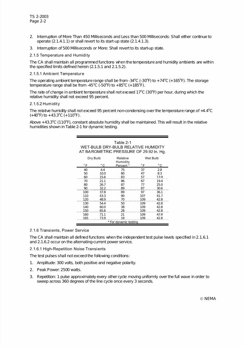
7/30/2019 NEMA TS2-2003- Traffic Controller Assemb
http://slidepdf.com/reader/full/nema-ts2-2003-traffic-controller-assemb 42/246
TS 2-2003Page 2-2
© NEMA
2. Interruption of More Than 450 Milliseconds and Less than 500 Milliseconds: Shall either continue tooperate (2.1.4.1.1) or shall revert to its start-up state (2.1.4.1.3).
3. Interruption of 500 Milliseconds or More: Shall revert to its start-up state.
2.1.5 Temperature and Humidi ty
The CA shall maintain all programmed functions when the temperature and humidity ambients are withinthe specified limits defined herein (2.1.5.1 and 2.1.5.2).
2.1.5.1 Ambient Temperature
The operating ambient temperature range shall be from -34oC (-30oF) to +74oC (+165oF). The storagetemperature range shall be from -45
oC (-50
oF) to +85
oC (+185
oF).
The rate of change in ambient temperature shall not exceed 17oC (30
oF) per hour, during which the
relative humidity shall not exceed 95 percent.
2.1.5.2 Humidit y
The relative humidity shall not exceed 95 percent non-condensing over the temperature range of +4.4oC
(+40oF) to +43.3
oC (+110
oF).
Above +43.3oC (110oF), constant absolute humidity shall be maintained. This will result in the relativehumidities shown in Table 2-1 for dynamic testing.
Table 2-1WET-BULB DRY-BULB RELATIVE HUMIDITY
AT BAROMETRIC PRESSURE OF 29.92 In. Hg.
Dry Bulb RelativeHumidity
Wet Bulb
oF
oC Percent *
oF
oC
40 4.4 75 37 2.850 10.0 80 47 8.360 15.6 83 57 13.9
70 21.1 86 67 19.480 26.7 87 77 25.090 32.2 89 87 30.6100 37.8 89 97 36.1110 43.3 90 107 41.7120 48.9 70 109 42.8130 54.4 50 109 42.8140 60.0 38 109 42.8150 65.6 28 109 42.8160 71.1 21 109 42.8165 73.9 18 109 42.8
* For dynamic testing
2.1.6 Transients, Power Service
The CA shall maintain all defined functions when the independent test pulse levels specified in 2.1.6.1
and 2.1.6.2 occur on the alternating-current power service.2.1.6.1 High-Repetition Noise Transients
The test pulses shall not exceed the following conditions:
1. Amplitude: 300 volts, both positive and negative polarity.
2. Peak Power: 2500 watts.
3. Repetition: 1 pulse approximately every other cycle moving uniformly over the full wave in order tosweep across 360 degrees of the line cycle once every 3 seconds.

7/30/2019 NEMA TS2-2003- Traffic Controller Assemb
http://slidepdf.com/reader/full/nema-ts2-2003-traffic-controller-assemb 43/246
TS 2-2003Page 2-3
© NEMA
4. Pulse Rise Time: 1 microsecond.
5. Pulse Width: 10 microseconds.
2.1.6.2 Low-Repetition High-Energy Transients
The test pulses shall not exceed the following conditions:
1. Amplitude: 600 volts +5 percent, both positive and negative polarity.
2. Energy Source: Capacitor, oil filled, 10 microfarads + 10 percent, internal surge impedance less than1 ohm.
3. Repetition: 1 discharge every 10 seconds.
4. Pulse Position: Random across 360 degrees of the line cycle.
2.1.7 Transients, Input-Output Terminals
The CA shall maintain all defined functions, when the test pulse occurs on the input-output terminals.
1. Amplitude: 300 volts, both positive and negative polarity.
2. Pulse Source: 1000 ohms nominal impedance.
3. Repetition: 1 pulse per second, for a minimum of 5 pulses per selected terminal.
4. Pulse rise time: 1 microsecond.
5. Pulse width: 10 microseconds.
2.1.8 Nondestruct Transient Immunity
The CA shall be capable of withstanding a high energy transient having the following characteristicsrepeatedly applied to the alternating current input terminals (no other power connected to terminals)without failure of the test specimen:
1. Amplitude: 1000 volts + 5 percent, both positive and negative polarity.
2. Energy Source: Capacitor, oil filled, 15 microfarads + 10 percent, internal surge impedance less than
1 ohm.3. Repetition: Applied to the CA once every 2 seconds for a maximum of three applications for each
polarity.
4. After the foregoing, the CA shall perform all defined functions upon the application of nominalalternating current power.
2.1.9 Vibration
The major units of the CA shall maintain all programmed functions and physical integrity when subjectedto a vibration of 5 to 30 Hz up to 0.5g’s applied in each of three mutually perpendicular planes.
2.1.10 Shock
The major units of the CA shall suffer neither permanent mechanical deformation nor any damage thatrenders the unit inoperable, when subjected to a shock of 10g applied in each of three mutuallyperpendicular planes.
2.2 CONTROLLER UNIT TESTS
The CU shall perform its specified functions under the conditions set forth in this Section. This Clausedefines the test procedures required to demonstrate the conformance of a CU type with the provisions of the standards.
In the interest of ensuring safe and reliable operation of the CU covered by these standards, the stresslevels which the tests encompass are nominal Worse-Case conditions the units experience in operation.
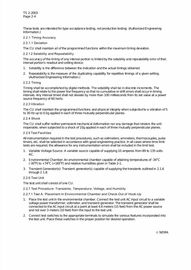
7/30/2019 NEMA TS2-2003- Traffic Controller Assemb
http://slidepdf.com/reader/full/nema-ts2-2003-traffic-controller-assemb 44/246

7/30/2019 NEMA TS2-2003- Traffic Controller Assemb
http://slidepdf.com/reader/full/nema-ts2-2003-traffic-controller-assemb 45/246
TS 2-2003Page 2-5
© NEMA
3. Verify the test hook-up. Adjust the variable-voltage power transformer to 120 volts AC and applypower to the test unit. Verify that the test unit goes through its prescribed start-up sequence andcycles properly in accordance with the operation determined by the positioning of test switches initem 2.
Upon the satisfactory completion and verification of the test hook-up, proceed with Test B.
2.2.7.2 Test B: Transient Tests (Power Service)
1. Program the test unit to dwell. Verify the input voltage is 120 volts AC.
2. Set the transient generator to provide high-repetition noise transients as follows:
a. Amplitude: 300 volts +5 percent, both positive and negative polarity.
b. Peak Power: 2500 watts.
c. Repetition Rate: One pulse every other cycle moving uniformly over the full wave in order tosweep once every 3 seconds across 360 degrees of line cycle.
d. Pulse Rise Time: 1 microsecond.
e. Pulse Width: 10 microseconds.
3. Apply the transient generator output to the AC voltage input for at least 5 minutes. Repeat this test forat least two conditions of dwell for the test unit. The test unit must continue to dwell withoutmalfunction.
4. Program the test unit to cycle. Turn on the transient generator (output in accordance with item 2) for10 minutes, during which time the test unit shall continue to cycle without malfunction.
5. Set a transient generator to provide high-repetition noise transients as follows:
a. Amplitude: 300 volts +5 percent, both positive and negative polarity.
b. Source Impedance: Not less than 1000 ohms nominal impedance.
c. Repetition: One pulse per second for a minimum of five pulses per selected terminal.
d. Pulse Rise Time: 1 microsecond.
e. Pulse Width: 10 microseconds.
Program the test unit to dwell. Verify the input voltage is 120 volts AC.
6. Apply the transient generator (output in accordance with item 5) between logic ground and theconnecting cable termination of selected Connector A, B, or C input/output terminals of the test unit.
A representative sampling of selected input/output terminations shall be tested. The test unit shallcontinue to dwell without malfunction.
7. Program the test unit to cycle. Turn on the transient generator (output in accordance with item 5) andapply its output to the selected Connector A, B, or C input/output terminations. The test unit shallcontinue to cycle without malfunction.
8. Set a transient generator to provide low-repetition high-energy transients as follows:
a. Amplitude: 600 volts +5 percent, both positive and negative polarity.
b. Energy Discharge Source: Capacitor, oil-filled, 10 microfarads.
c. Repetition Rate: One discharge each 10 seconds.
d. Pulse Position: Random across 360 degrees of line cycle.
9. Program the test unit to dwell. Verify the input voltage is 120 volts AC.
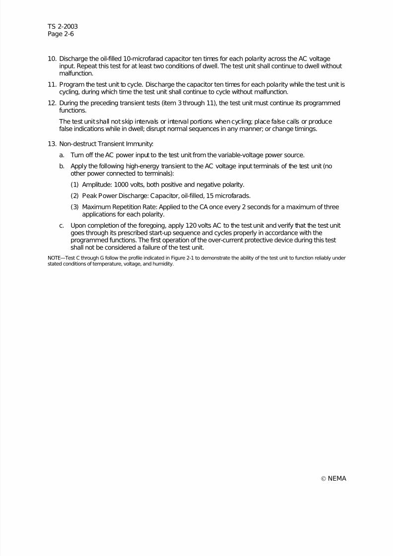
7/30/2019 NEMA TS2-2003- Traffic Controller Assemb
http://slidepdf.com/reader/full/nema-ts2-2003-traffic-controller-assemb 46/246
TS 2-2003Page 2-6
© NEMA
10. Discharge the oil-filled 10-microfarad capacitor ten times for each polarity across the AC voltageinput. Repeat this test for at least two conditions of dwell. The test unit shall continue to dwell withoutmalfunction.
11. Program the test unit to cycle. Discharge the capacitor ten times for each polarity while the test unit iscycling, during which time the test unit shall continue to cycle without malfunction.
12. During the preceding transient tests (item 3 through 11), the test unit must continue its programmedfunctions.
The test unit shall not skip intervals or interval portions when cycling; place false calls or producefalse indications while in dwell; disrupt normal sequences in any manner; or change timings.
13. Non-destruct Transient Immunity:
a. Turn off the AC power input to the test unit from the variable-voltage power source.
b. Apply the following high-energy transient to the AC voltage input terminals of the test unit (noother power connected to terminals):
(1) Amplitude: 1000 volts, both positive and negative polarity.
(2) Peak Power Discharge: Capacitor, oil-filled, 15 microfarads.
(3) Maximum Repetition Rate: Applied to the CA once every 2 seconds for a maximum of threeapplications for each polarity.
c. Upon completion of the foregoing, apply 120 volts AC to the test unit and verify that the test unitgoes through its prescribed start-up sequence and cycles properly in accordance with theprogrammed functions. The first operation of the over-current protective device during this testshall not be considered a failure of the test unit.
NOTE—Test C through G follow the profile indicated in Figure 2-1 to demonstrate the ability of the test unit to function reliably understated conditions of temperature, voltage, and humidity.
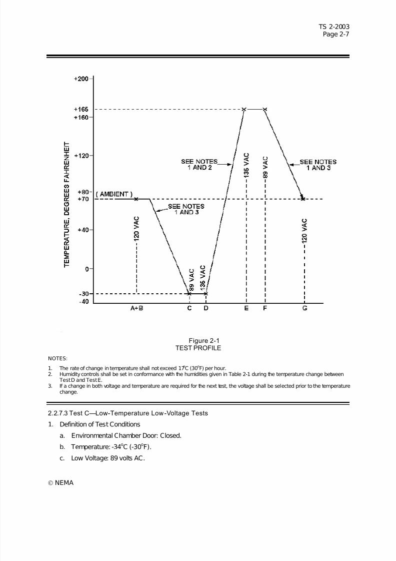
7/30/2019 NEMA TS2-2003- Traffic Controller Assemb
http://slidepdf.com/reader/full/nema-ts2-2003-traffic-controller-assemb 47/246
7/30/2019 NEMA TS2-2003- Traffic Controller Assemb
http://slidepdf.com/reader/full/nema-ts2-2003-traffic-controller-assemb 48/246
TS 2-2003Page 2-8
© NEMA
d. Humidity Control: Off.
2. Test Procedure: While at room temperature, adjust the input voltage to 89 volts AC and verify that thetest unit is still operable.
a. With the test unit cycling, lower the test chamber to -34oC (-30
oF) at a rate not exceeding 17
oC
(30o
F) per hour. Allow the test unit to cycle for a minimum of 5 hours at -34o
C (-30o
F) with thehumidity controls in the off position. Then operate the test switches as necessary to determinethat all functions are operable.
b. Power shall then be removed from the test unit for a minimum period of 5 hours. Upon restorationof power, the test unit shall go through its prescribed start-up sequence and then resume cycling.
c. With the test unit at -34oC (-30oF) and the input voltage at 89 volts AC, the following items shallbe evaluated against the respective standards:
1) 2.2.10 Power Interruption Tests
2) 2.2.11 Timing Accuracy Tests
3) 2.2.11.2 Repeatability
On satisfactory completion of this test, proceed with Test D.2.2.7.4 Test D—Low-Temperature High-Voltage Tests
1. Definition of Test Conditions
a. Environmental Chamber Door: closed.
b. Low Temperature: -34oC (-30
oF)
c. High Voltage: 135 volts AC.
d. Humidity Controls: off.
2. Test Procedure: While at -34oC (-30
oF) and with humidity controls off, adjust the input voltage to 135
volts AC and allow the test unit to cycle for 1 hour. Then operate the test switches as necessary todetermine that all functions are operable.
3. With the test unit at -34oC (-30oF) and the input voltage at 135 volts AC (humidity controls off), thefollowing items shall be evaluated against the respective standards:
a. 2.2.10 Power Interruption Tests
b. 2.2.11 Timing Accuracy Tests
c. 2.2.11.2 Repeatability
On satisfactory completion of this test, proceed to Test E.
2.2.7.5 Test E—High-Temperature High-Voltage Tests
1. Definition of Test Conditions
a. Environmental Chamber Door: Closed.
b. High Temperature: 74oC (+165oF).
c. High Voltage: 135 volts AC.
d. Humidity Controls: In accordance with the humidities given in Table 2-1.
2. Test Procedure—With the test unit cycling, raise the test chamber to +74oC (+165
oF) at a rate not to
exceed 17oC (30
oF) per hour. Verify the input voltage is 135 volts AC.
3. Set the humidity controls to not exceed 95 percent relative humidity over the temperature range of 4.4
oC (40
oF) to 43.3
oC (110
oF). When the temperature reaches 43
oC (109
oF), readjust the humidity
7/30/2019 NEMA TS2-2003- Traffic Controller Assemb
http://slidepdf.com/reader/full/nema-ts2-2003-traffic-controller-assemb 49/246
TS 2-2003Page 2-9
© NEMA
control to maintain constant absolute humidity; 43oC (109
oF) wet bulb which results in the relative
humidities shown in Table 2-1. Verify that the test unit continues to cycle satisfactory during theperiod of temperature increase and at established levels of relative humidity.
a. Allow the test unit to cycle for a minimum of 15 hours at 74oC (165oF) and 18 percent relativehumidity. Then operate the test switches as necessary to determine that all functions are
operable.
b. With the test unit at 74oC (165
oF) and 18 percent relative humidity and the input voltage at 135
volts AC, the following items shall be evaluated against the respective standards:
1) 2.2.10 Power Interruption Tests
2) 2.2.11 Timing Accuracy Tests
3) 2.2.11.2 Repeatability
On satisfactory completion of this test, proceed to Test F.
2.2.7.6 Test F—High-Temperature Low-Voltage Tests
1. Definition of Test Conditions
a. Environmental Chamber Door: Closed.
b. High Temperature: 74oC (165
oF).
c. Low Voltage: 89 volts AC.
d. Humidity Controls: 18 percent relative humidity and 43oC (109
oF) wet bulb.
2. Test Procedure: Adjust the input voltage to 89 volts AC and proceed to operate the test switches todetermine that all functions are operable. With the test unit at 74
oC (165
oF) and 18 percent relative
humidity, 43oC (109oF) wet bulb, and the input voltage at 89 volts AC, the following items shall beevaluated against the respective standards:
2.2.10 Power Interruption Tests
2.2.11 Timing Accuracy Tests
2.2.11.2 Repeatability
On satisfactory completion of this test, proceed to Test G.
2.2.7.7 Test G—Test Termination
1. Program the test unit to cycle.
2. Adjust the input voltage to 120 volts AC.
3. Set the controls on the environmental chamber to return to room temperature, 15oC (60
oF) to 27
oC
(80oF), with the humidity controls in the off position. The rate of temperature change shall not exceed
17oC (30
oF) per hour.
4. Verify the test unit continues to cycle properly.
5. Allow the test unit to stabilize at room temperature for 1 hour. Proceed to operate the test switches todetermine that all functions are operable.
2.2.7.8 Test H—Appraisal Of Equipment Under Test
1. A failure shall be defined as any occurrence which results in other than normal operation of theequipment. (See item 2 for details.) If a failure occurs, the test unit shall be repaired or componentsreplaced, and the test during which failure occurred shall be restarted from its beginning.
2. The test unit is considered to have failed if any of the following occur:
7/30/2019 NEMA TS2-2003- Traffic Controller Assemb
http://slidepdf.com/reader/full/nema-ts2-2003-traffic-controller-assemb 50/246
TS 2-2003Page 2-10
© NEMA
a. If the test unit skips intervals or interval portions, places false calls, presents false indications,exhibits disruption of normal sequence, or produces changes in timing beyond specifiedtolerances, or
b. If the test unit fails to satisfy the requirements of 2.2.7 Tests A to G, inclusive.
3. An analysis of the failure shall be performed and corrective action taken before the test unit isretested in accordance with this standard. The analysis must outline what action was taken topreclude additional failures during the tests.
4. When the number of failures exceeds two, it shall be considered that the test unit fails to meet thesestandards. The test unit may be completely retested after analysis of the failure and necessaryrepairs have been made in accordance with item 3.
5. Upon completion of the tests, the test unit shall be visually inspected. If material changes areobserved which will adversely affect the life of the test unit, the cause and conditions shall becorrected before making further tests.
6. Upon satisfactory completion of all of the tests described in 2.2.7.1 through 2.2.7.7, the test unit shallbe tested in accordance with 2.2.8.
2.2.8 Vibration Test2.2.8.1 Purpose of Test
This test is intended to duplicate vibrations encountered by the test unit when installed at its street-corner location.
The test unit shall be fastened securely to the vibration test table prior to the start of the test.
2.2.8.2 Test Equipment Requi rements
1. Vibration table with adequate table surface area to permit placement of the test unit.
2. Vibration test shall consist of:
a. Vibration in each of three mutually perpendicular planes.
b. Adjustment of frequency of vibration over the range from 5 to 30 Hertz.
c. Adjustment of test table excursion (double amplitude displacement) to maintain a ‘g’ value,measured at the test table, of 0.5g; as determined by the following formula:
g =0.0511df 2
Where:
d =excursion in inches
f =frequency in Hertz
2.2.8.3 Resonant Search
1. With the test unit securely fastened to the test table, set the test table for a double amplitudedisplacement of 0.015 inch.
2. Cycle the test table over a search range from 5 to 30 Hz and back within a period of 12-1/2 minutes.
3. Conduct the resonant frequency search in each of the three mutually perpendicular planes.
4. Note and record the resonant frequency determined from each plane.
a. In the event of more than on resonant frequency in a given plane, record the most severeresonance.
b. If resonant frequencies appear equally severe, record each resonant frequency.

7/30/2019 NEMA TS2-2003- Traffic Controller Assemb
http://slidepdf.com/reader/full/nema-ts2-2003-traffic-controller-assemb 51/246
TS 2-2003Page 2-11
© NEMA
c. If no resonant frequency occurs for a given plane within the prescribed range, 30 Hz shall berecorded.
2.2.8.4 Endurance Test
1. Vibrate the test unit in each plane at its resonant frequency for a period of 1 hour at an amplitude
resulting in 0.5g acceleration.2. When more than one resonant frequency has been recorded in accordance with 2.2.8.3.4, the test
period of 1 hour shall be divided equally between the resonant frequencies.
3. The total time of the endurance test shall be limited to 3 hours, 1 hour in each of three mutuallyperpendicular planes.
2.2.8.5 Disposition of Equipment Under Test
1. The test unit shall be examined to determine that no physical damage has resulted from the vibrationtests.
2. The test unit shall be checked to determine that it is functionally operable in all modes of itsprescribed operation.
3. The test unit may be removed from the test table. Upon satisfactory completion of the vibration test,proceed with the shock (impact) test described in 2.2.9.
2.2.9 Shock (Impact) Test
2.2.9.1 Purpose of Test
The purpose of this test is to determine that the test unit is capable of withstanding the shock (impact) towhich it may reasonably be subjected during handling and transportation in the process of installation,repair, and replacement. It is to be noted that the test unit is not, at this time, in its shipping carton.
The test unit shall be firmly fastened to the specimen table. In each of its three planes the test unit shallbe dropped from a calibrated height to result in a shock force of 10g.
2.2.9.2 Test Equipment Requi rements
1. Shock (impact) test fixture equivalent to that suggested by the simplified sketch shown in Figure 2-2.
2. The test table shall have a surface area sufficient to accommodate the test unit.
3. The test table shall be calibrated and the items tested as indicated. This shock test defines the testshock to be 10g +1g.
a. Calibration of the test equipment for these shock tests shall be measured by threeaccelerometers having fixed shock settings of 9g, 10g, and 11g. They shall be Inertia SwitchIncorporated ST-355, or the equivalent. These devices shall be rigidly attached to the test table.
b. Calibration of the fixture for each item to be tested shall be as follows:
1) Place a dummy load weighing within 10 percent of the test unit on the table.
2) Reset the three accelerometers and drop the test table from a measured height.
3) Observe that the accelerometers indicate the following:
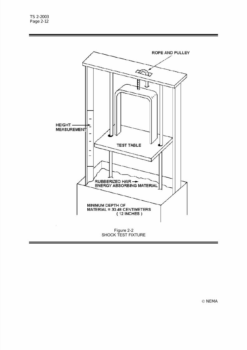
7/30/2019 NEMA TS2-2003- Traffic Controller Assemb
http://slidepdf.com/reader/full/nema-ts2-2003-traffic-controller-assemb 52/246
TS 2-2003Page 2-12
© NEMA
Figure 2-2SHOCK TEST FIXTURE

7/30/2019 NEMA TS2-2003- Traffic Controller Assemb
http://slidepdf.com/reader/full/nema-ts2-2003-traffic-controller-assemb 53/246
TS 2-2003Page 2-13
© NEMA
a) The 9g accelerometer shall be activated.
b) The 10g unit may or may not be actuated.
c) The 11g unit shall not be actuated.c. Repeat calibration test (a) and (b) adjusting the height of the drop until, on ten successive drops,
the following occurs:
1) The 9g unit is actuated ten times.
2) The 10g unit is actuated between four to eight times.
3) The 11g unit is not actuated on any of the ten drops.
2.2.9.3 Test Procedure
1. The calibration height of the drop for the particular item under test as determined in 2.2.9.2 shall beused in this procedure.
2. Secure the test unit to the test table surface so that the test unit rests on one of its three mutually
perpendicular planes.
3. Raise the test table to the calibrated height.
4. Release the test table from the calibrated height, allowing a free fall into the box of energy absorbingmaterial below.
5. Repeat the drop test for each of the remaining two mutually perpendicular planes, using the samecalibrated height for each drop test of the same test unit.
6. The observations of the accelerometer for the three tests of the test item shall be:
a. The 9g unit is actuated for all three tests. (Repeat the calibration if the unit is not actuated.)
b. The 10g unit may or may not be actuated in these tests.
c. The 11g unit is not actuated on any drop. (If the unit is actuated, repeat the calibration only if thetest unit has suffered damage.)
2.2.9.4 Disposit ion o f Test Unit
1. Check the test unit for any physical damage resulting from the drop tests.
2. Check the test unit to determine that it is functionally operable in all modes of its prescribed operation.
3. Satisfactory completion of all environmental tests, including the shock (impact) is required.
2.2.10 Power Interruption Tests
The following power interruption tests shall be conducted at low input voltage (89 volts AC) and high inputvoltage (135 volts AC) at -34oC (-30oF), and +74oC (+165oF).
2.2.10.1 500-Milli second Power Interrupt ion
While the test unit is cycling, remove the input voltage for a period of 500 milliseconds. Upon restorationof the input voltage, check to insure that the test unit continues normal operation as though no powerinterruption has occurred. Repeat this test three times.
2.2.10.2 1000-Millisecond Power Interruption
While the test unit is cycling, remove the input voltage for a period of 1000 milliseconds. Upon restorationof the input voltage, check to insure that the test unit reverts to its start-up sequence. Repeat this testthree times.

7/30/2019 NEMA TS2-2003- Traffic Controller Assemb
http://slidepdf.com/reader/full/nema-ts2-2003-traffic-controller-assemb 54/246
TS 2-2003Page 2-14
© NEMA
2.2.11 Timing Accuracy Tests
A sampling of at least four intervals (or interval portions) shall be timed as specified in the followingprocedure.
2.2.11.1 Setability
The range of timing shall, as a minimum requirement, be as shown in 3.4.2.1 or 3.5.3.1.
The range of timing and setability requirements shall be in accordance with the functional standards givenin this publication.
Determine that the setting of the interval time has been provided in positive discrete increments inaccordance with the functional standards given in this publication for the specific test unit.
2.2.11.2 Repeatability
At all stabilized temperatures specified in 2.2.7.2 through 2.2.7.7, each interval shall be timed with thedigital time indicator for ten consecutive cycles for one given setting for each interval.
Any interval timed shall not deviate by more than +100 milliseconds from its set value.
2.3 MALFUNCTION MANAGEMENT UNIT TESTS The MMU shall perform its specified functions under the conditions set forth in this Section. This Clausedefines the test procedures required to demonstrate the conformance of a MMU with the provisions of thestandards.
In the interest of ensuring safe and reliable operation of the MMU covered by these standards, the stresslevels which the tests encompass are nominal Worst Case conditions the units may experience inoperation. These tests are intended for type acceptance testing and not production testing. (AuthorizedEngineering Information.)
2.3.1 Test Facili ties
1. A variable AC voltage source capable of providing AC test voltages from 0 to 135 volts RMS AC, 5amperes minimum capacity.
2. Test probe or test fixture to provide a means of applying the test voltage specified in item #1 toselected field terminal inputs of the MMU.
3. A true RMS responding voltmeter to provide means of detecting a test voltage of 0 to 150 volts RMSAC. The voltmeter shall display actual RMS voltages without additional computation required. Thetrue RMS meter shall measure a 60 Hz half wave sinusoidal signal with a peak voltage of 50 volts as25 volts RMS.
4. A digital time indicator with sufficient scale to cover the range and resolution of timings to be takenand with a readout capability of at least 0.01 seconds.
5. Milliamp meter.
6. A variable direct current voltage source capable of providing 0.5 amperes from 0 to 30 VDC.
7. Test probe or test fixture provide a means of applying the test voltage in item #6 to selected inputs.See 4.3.3.5 and 4.3.3.6 of the MMU.
8. A transient generator capable of supplying the transients outlined in 2.1.6 through 2.1.8.
9. Test fixture capable of providing Port 1 communications with the MMU as outlined in 3.3.1 (Port 1Physical and Protocol).
2.3.2 Standard Setup
Unless otherwise specified the MMU shall be set up as follows:
1. No fault state at the beginning of each test.
7/30/2019 NEMA TS2-2003- Traffic Controller Assemb
http://slidepdf.com/reader/full/nema-ts2-2003-traffic-controller-assemb 55/246
TS 2-2003Page 2-15
© NEMA
2. All Green, Yellow, and Walk inputs shall be zero volts.
3. All Red inputs shall be connected to AC Line.
4. Red Enable shall be zero volts AC.
5. The two +24 Volt Monitor inputs shall be connected to 24 volts DC.
6. +24 Volt Monitor Inhibit input and CVM input shall be zero volts DC.
7. MMU set up for non-latching voltage monitoring faults.
8. Program card programmed for no compatible channels.
9. MMU set up to operate as a type 12, without Port 1 communications.
Where AC Line is specified it is meant to mean any voltage from 89 volts RMS AC to 135 volts RMS AC.
2.3.3 Ground Isolation Test
Measure resistance between AC Neut ral and Logic Ground to verify that it exceeds 10 megohms.
2.3.4 1500 pF Input Test
With AC Line applied to any Green, Yellow, orWalk input apply 135 volts RMS AC through a 1500 pFcapacitor to each of the other Green, Yellow, and Walk inputs one at a time for 1 second. Verify that noconflicts are recognized. Repeat test with AC Line applied to a different Green, Yellow, or Walk input andverify that the input used for the first part of the test also does not cause a conflict to a 135 volts RMS ACsignal applied through 1500 pF.
2.3.5 Confl ict Low Vol tage Test
1. Apply AC Line to one conflicting input and apply 15 volts RMS AC full wave signal to all other Green,Yellow, and Walk inputs for one second. Verify that no conflict is recognized within that interval.Repeat with AC Line on a different channel.
2. Same as 2.3.5.1 with 15 volts RMS AC (30 V peak 60 Hz) positive half wave signal.
3. Same as 2.3.5.1 with 15 volts RMS AC (30 V peak 60 Hz) negative half wave signal.
2.3.6 Confl ict High Voltage Test
1. Apply AC Line to one conflicting input and apply 25 volts RMS AC full wave signal to each of theother Green, Yellow, orWalk inputs. Verify that a conflict is recognized and the Output relaycontacts transfer to the fault condition within the time parameters specified in 4.4.3. Repeat with ACLine on a different conflicting input to verify that the first input also responds correctly to 25 volts RMSAC input.
2. Same as 2.3.6.1 with 25 volts RMS AC (50 V peak 60 Hz) positive half wave signal.
3. Same as 2.3.6.1 with 25 volts RMS AC (50 V peak 60 Hz) negative half wave signal.
4. With the MMU in a Conflict fault state, verify that the MMU remains in the Conflict fault state after theremoval of the conflicting signals. Remove AC power from the MMU, allow enough time for theinternal power supplies to Bleed down to 0 VDC before restoring AC power to the MMU. Verify that
the AC power interruption does not cause reset of the fault or alter any fault data display indications.2.3.7 Red Input Test
1. Apply 89 volts RMS AC to the Red Enable input. With all other Red inputs at AC Line, apply 50 voltsRMS AC to each Red input and verify that a Red Failure is recognized and the Output relay contactstransfer to the fault condition within the time parameters specified in 4.4.4.
2. With the MMU in the Red Failure state, verify that the MMU remains in the Red Failure state after theremoval of the Red Failure. Remove AC power from the MMU, allow enough time for the internal
7/30/2019 NEMA TS2-2003- Traffic Controller Assemb
http://slidepdf.com/reader/full/nema-ts2-2003-traffic-controller-assemb 56/246
TS 2-2003Page 2-16
© NEMA
power supplies to Bleed down to 0 VDC before restoring AC power to the MMU. Verify that the ACpower interruption does not cause reset of the fault or alter any fault data display indications.
3. Apply 89 volts RMS AC to the Red Enable input. Apply 70 volts RMS AC to all Red inputs for at least2 seconds and verify that no faults are recognized within that interval.
4. With Red Enable input at 70 volts RMS AC and Red inputs at zero volts for at least 2 seconds, verifythat no faults are recognized within that interval.
2.3.8 Minimum Yellow Change/Red Clearance Interval
1. With Red Enable signal connected to AC Line and all channels programmed to disable Minimum Yellow Change monitoring, apply the following sequence to any conflicting channels:
Channel A: Green Red
<-- 2.6 sec. Or less -->
Channel B: Red Green
Verify that the MMU recognizes a 2.6 second or less clearance time (Yellow + Red) as a Minimum Yellow Change / Red Clearance failure. Verify that all other pairs of conflicting channels respondcorrectly to a Minimum Yellow Change / Red Clearance failure.
2. With Red Enable signal connected to AC Line, apply the following sequence to any channel enabledto monitor minimum Yellow Change interval:
Channel N: Green Yellow Red
<-- 2.6 sec. Or less -->
Verify that a 2.6 second or less Yellow Change interval is detected as a Minimum Yellow Change /
Red Clearance failure.
3. With the MMU in the Minimum Yellow Change/Red Clearance fault state, remove AC power from theMMU, allow enough time for the internal power supplies to Bleed down to 0 VDC before restoring ACpower to the MMU. Verify that the AC power interruption does not cause reset of the fault or alter anyfault data display indications.
2.3.9 Port 1 Timeout
With the MMU setup with Port 1 communications and the Type Select input setTrue (Low), verify thatthe Output relay contacts transfer to the fault condition after 300 milliseconds but before 400 millisecondsif a Type 0 frame is not received within this interval. Verify that no timeout occurs if the Port 1 Disable input is a True (Low) state.
2.3.10 DC Voltage Moni toring
For tests 2.3.10.1 to 2.3.10.6 apply 24 VDC to the +24 Volt Inhib it input.
1. Apply 22 VDC to both +24 Volt Monitor inputs. Verify that the MMU is in the no fault condition.
2. Apply 18 VDC to each +24 Volt Monitor input with the other input at 22 volts. Verify that applying the18 VDC to either input is recognized as a +24 Volt Failure and the Output relay contacts transfer tothe fault condition within the time parameter specified in 4.4.7.1. Verify that reapplying 22 VDC to theinput(s) being tested restores the MMU to the no fault condition.
7/30/2019 NEMA TS2-2003- Traffic Controller Assemb
http://slidepdf.com/reader/full/nema-ts2-2003-traffic-controller-assemb 57/246
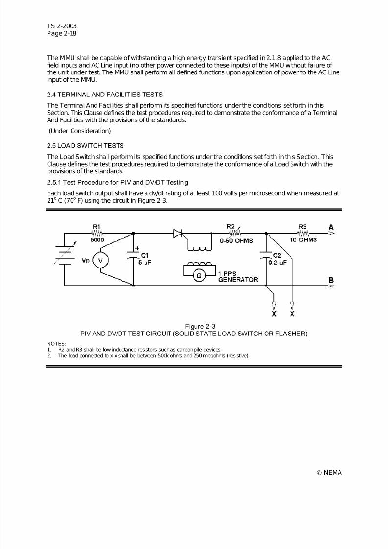
7/30/2019 NEMA TS2-2003- Traffic Controller Assemb
http://slidepdf.com/reader/full/nema-ts2-2003-traffic-controller-assemb 58/246
7/30/2019 NEMA TS2-2003- Traffic Controller Assemb
http://slidepdf.com/reader/full/nema-ts2-2003-traffic-controller-assemb 59/246
TS 2-2003Page 2-19
© NEMA
1. With the power removed from the load, connect pins 1 (AC Line) and 11 (AC Neutral) of the loadswitch to terminal A of the test circuit.
2. Connect terminal B of the test circuit to pin 3 (Circuit A) of the load switch.
3. Set Vp to 500 VDC.
4. Decrease R2 until the load switch output conducts or the value of R2 reaches zero. If the load switchstarts conducting when the test pulse is applied, back R2 off slightly to a higher resistance pointabove which the load switch does not conduct. Conduction of the load switch circuit due to either PIVor DV/DT can be observed by the flickering or dipping of the Vp meter.
5. Measure the time required for the wave form at points x-x to reach 200 VDC DV/DT =200/timemeasured.
6. Repeat the test steps 4 and 5 with terminals A and B of the test circuit reversed.
7. Connect terminal B of the test circuit to pin 5 (Circuit B) of the load switch and connect terminal A of the test circuit to pins 1 and 11 of the load switch.
8. Repeat steps 3 through 6 for circuit B of the load switch.
9. Connect terminal B of the test circuit to pin 7 (Circuit C) of the load switch and connect terminal A of the test circuit to pins 1 and 11 of the load switch.
10. Repeat steps 3 through 6 for circuit C of the load switch.
2.6 FLASHER TESTS
The Flasher shall perform its specified functions under the conditions set forth in this Section. This Clausedefines the test procedures required to demonstrate the conformance of a Flasher with the provisions of the standards.
2.6.1 Test Procedure for PIV and DV/DT Testing
The flasher output shall have a dv/dt rating of at least 100 volts per microsecond when measured at 21o
C(70
oF) using the circuit in Figure 2-3.
1. Connect pins 10 and 11 of the flasher to terminal A of the test circuit.
2. Connect terminal B of the test circuit to pin 7 of the flasher.
3. Set Vp to 500 VDC.
4. Decrease R2 until the flasher generates an output or the minimum resistance is reached. If theflasher fails, back off R2 slightly to higher resistance point at which the flasher just passes.Conduction of a flasher circuit due to either PIV or DV/DT can be observed by the flickering or dippingof the Vp meter.
5. Measure time required for wave at points x-x to reach 200 VDC DV/DT =200/time measured.
6. Repeat the test with the connector pins A and B reversed.
7. Repeat steps 1 through 6 with terminal B of the test fixture connected to pin 8 of the flasher.
2.7 FLASH TRANSFER RELAY TESTS
The Flash Transfer Relay shall perform its specified functions under the conditions set forth in thisSection. This Clause defines the test procedures required to demonstrate the conformance of a Flash Transfer Relay with the provisions of the standards.
(Under Consideration)
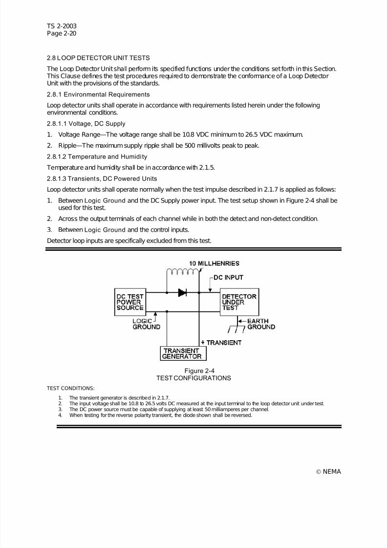
7/30/2019 NEMA TS2-2003- Traffic Controller Assemb
http://slidepdf.com/reader/full/nema-ts2-2003-traffic-controller-assemb 60/246
TS 2-2003Page 2-20
© NEMA
2.8 LOOP DETECTOR UNIT TESTS
The Loop Detector Unit shall perform its specified functions under the conditions set forth in this Section. This Clause defines the test procedures required to demonstrate the conformance of a Loop DetectorUnit with the provisions of the standards.
2.8.1 Environmental RequirementsLoop detector units shall operate in accordance with requirements listed herein under the followingenvironmental conditions.
2.8.1.1 Voltage, DC Supply
1. Voltage Range—The voltage range shall be 10.8 VDC minimum to 26.5 VDC maximum.
2. Ripple—The maximum supply ripple shall be 500 millivolts peak to peak.
2.8.1.2 Temperature and Humidi ty
Temperature and humidity shall be in accordance with 2.1.5.
2.8.1.3 Transients, DC Powered Units
Loop detector units shall operate normally when the test impulse described in 2.1.7 is applied as follows:1. Between Logic Ground and the DC Supply power input. The test setup shown in Figure 2-4 shall be
used for this test.
2. Across the output terminals of each channel while in both the detect and non-detect condition.
3. Between Logic Ground and the control inputs.
Detector loop inputs are specifically excluded from this test.
Figure 2-4TEST CONFIGURATIONS
TEST CONDITIONS:
1. The transient generator is described in 2.1.7.2. The input voltage shall be 10.8 to 26.5 volts DC measured at the input terminal to the loop detector unit under test.3. The DC power source must be capable of supplying at least 50 milliamperes per channel.4. When testing for the reverse polarity transient, the diode shown shall be reversed.
7/30/2019 NEMA TS2-2003- Traffic Controller Assemb
http://slidepdf.com/reader/full/nema-ts2-2003-traffic-controller-assemb 61/246
TS 2-2003Page 2-21
© NEMA
2.8.1.4 Transients, Loop Detector Input Terminals
The loop detector unit shall be capable of withstanding the eight nondestructive transient tests describedin Figure 2-5. Each test shall be repeated 10 times with the loop detector unit operating from its normalpower source. The time between repetitions shall not exceed 10 seconds.
The energy source shall be a capacitor, oil filled, 10 microfarads +5 percent, internal surge impedanceless than 1 ohm connected in accordance with Figure 2-5. The voltage on the capacitor shall be adjustedas described herein. The test push button shall be activated for at least one second for each of the eightytest repetitions.
After the foregoing tests, the loop detector unit shall operate normally.
1. Test Numbers 1 and 5. The Loop detector unit shall withstand the discharge of a 10 microfaradcapacitor charged to + 1000 volts applied directly across the loop detector unit sensor loop input pinswith no sensor loop load present.
2. Test Numbers 2, 3, 4, 6, 7, and 8. The loop detector unit shall withstand the discharge of a 10microfarad capacitor charged to + 2000 volts applied directly across either the loop detector unitsensor loop input pins or from either side of the sensor loop input pins to equipment ground. The loopdetector unit sensor loop input pins shall have a dummy resistive load attached equal to 5.0 ohms +
10 percent.
2.8.1.5 Vibration
The loop detector unit shall maintain both its physical integrity and operating characteristics after beingsubjected to the vibration test in 2.2.8. This test shall be run at nominal voltage and room environmentalconditions.
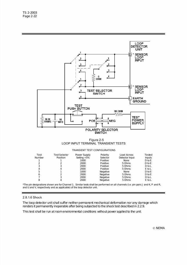
7/30/2019 NEMA TS2-2003- Traffic Controller Assemb
http://slidepdf.com/reader/full/nema-ts2-2003-traffic-controller-assemb 62/246
TS 2-2003Page 2-22
© NEMA
Figure 2-5LOOP INPUT TERMINAL TRANSIENT TESTS
TRANSIENT TEST CONFIGURATIONS
TestNumber
Test SelectorPosition
Power SupplySetting +5%
PolaritySelector
Load AcrossDetector Input
TestedInputs
1 1 1000 Positive None D to E2 2 2000 Positive 5 Ohms D to E3 3 2000 Positive 5 Ohms D to L4 4 2000 Positive 5 Ohms E to L5 1 1000 Negative None D to E6 2 2000 Negative 5 Ohms D to E7 3 2000 Negative 5 Ohms D to L8 4 2000 Negative 5 Ohms E to L
*The pin designations shown are for Channel 1. Similar tests shall be performed on all channels (i.e. pin pairs J and K, P and R,and U and V, respectively and as applicable) of the loop detector unit.
2.8.1.6 Shock
The loop detector unit shall suffer neither permanent mechanical deformation nor any damage whichrenders it permanently inoperable after being subjected to the shock test described in 2.2.9.
This test shall be run at room environmental conditions without power applied to the unit.

7/30/2019 NEMA TS2-2003- Traffic Controller Assemb
http://slidepdf.com/reader/full/nema-ts2-2003-traffic-controller-assemb 63/246
TS 2-2003Page 2-23
© NEMA
2.9 BUS INTERFACE UNIT TESTS
The Bus Interface Unit shall perform its specified functions under the conditions set forth in this Section. This Clause defines the test procedures required to demonstrate the conformance of a Bus Interface Unitwith the provisions of the standards.
(Under Consideration)

7/30/2019 NEMA TS2-2003- Traffic Controller Assemb
http://slidepdf.com/reader/full/nema-ts2-2003-traffic-controller-assemb 64/246
TS 2-2003Page 2-24
© NEMA
7/30/2019 NEMA TS2-2003- Traffic Controller Assemb
http://slidepdf.com/reader/full/nema-ts2-2003-traffic-controller-assemb 65/246

7/30/2019 NEMA TS2-2003- Traffic Controller Assemb
http://slidepdf.com/reader/full/nema-ts2-2003-traffic-controller-assemb 66/246
TS 2-2003Page 3-2
© NEMA
3.2.3.2 Mating Surfaces
All electrical mating surfaces shall be made of noncorrosive material.
3.2.3.3 Component Identification
The Printed Circuit Assembly shall be so designed that each component is identified with a circuitreference symbol. The identification shall be etched or silkscreened on circuit boards.
3.3 INTERFACE STANDARDS
This standard shall define Types 1 and 2 CUs.
Type A1 and P1 CUs shall utilize an Input / Output Interface conforming to the requirements of 3.3.1 forall Input / Output functions with the Terminals and Facilities, Malfunction Management Unit, DetectorRack(s), and Auxiliary Devices.
Type A2 and P2 CUs shall utilize an Input / Output Interface conforming to the requirements of 3.3.1 forInput / Output functions with the Malfunction Management Unit and Detector Rack(s) and 3.3.5 for Input /Output functions with the TF, Detector(s), and Auxiliary Devices.
Type A2 CUs are included for the purpose of upgrading existing TS 1 installations (Authorized
Engineering Information).
If input/output terminations in addition to those covered by these standards are required to allow inclusionof additional functional capabilities, such additional input/output terminations shall be provided on anadditional connector. Such additional connector shall not be interchangeable with other connector(s) onthe face of the CU. The provision of these additional functional capabilities shall not modify the operatingcapabilities of the CU covered by these standards when the additional input/output connector isdisconnected.
The CU shall provide an input/output interface to meet the following requirements.
3.3.1 Port 1 Physical and Protocol
3.3.1.1 Connector
The Port 1 connector shall be a 15 pin metal shell D sub-miniature type connector. The connector shallutilize female contacts with 15 millionths of an inch minimum gold plating in the mating area. Theconnector shall be equipped with latching blocks. The connector shall intermate with a 15 pin D typeconnector, Amp Incorporated part number 205206-1, or equivalent, which is equipped with spring latches,Amp Incorporated part number 745012-1, or equivalent. Pin connections shall be as follows:
Pin Function1 Tx Data +2 Logic Ground3 Tx Clock +4 Logic Ground5 Rx Data +6 Logic Ground7 Rx Clock +8 Logic Ground9 Tx Data -10 Port 1 Disable (0VDC=disable) (*)11 Tx Clock -12 Earth Ground13 Rx Data -14 Reserved15 Rx Clock -
* Pin 10 shall be connected to pin 8 when it is desirable to disable all Port 1 communicationsactivity. This shall be accomplished by mating a connector (as described above) to this Port 1connector, in which pin 8 and pin 10 are connected.
7/30/2019 NEMA TS2-2003- Traffic Controller Assemb
http://slidepdf.com/reader/full/nema-ts2-2003-traffic-controller-assemb 67/246
TS 2-2003Page 3-3
© NEMA
Port 1 shall be utilized to facilitate communications between the CU, the TF, the MMU, and the DRs, asdefined in this standard. Port 1 may also be used for manufacturer's use. In such instances, conformancewith this standard shall be required.
It will be necessary to disable all Port 1 communications activity when a CU meeting the requirements of this standard is installed in a CA that has no accommodations for Port 1, such as a CA meeting the
requirements of NEMA Standard TS 1-1989. (Authorized Engineering Information.)
3.3.1.2 Electrical Interface
3.3.1.2.1 Logic Ground and Earth Ground
1. Logic Ground—Voltage reference point and current return point for CU input and output logiccircuits. This output shall not be connected to AC Neutral orEarth Ground within the CU.
2. Earth Ground—Terminal for connection to the chassis of the CU. Earth Ground shall be electricallyconnected to the shell of the connector(s) where applicable. This input shall not be connected toLogic Ground or AC Neutral within the CU.
3.3.1.2.2 Data and Clock Links
1. Tx Data +, Tx Data -, Tx Clock +, Tx Clock -, Rx Data +, Rx Data -, Rx Clock +, and Rx Clock -
shall consist of four interface links conforming to the requirements of the Electronic IndustriesAssociation EIA-485, Standard for Electrical Characteristics of Generators and Receivers for use inBalanced Digital Multipoint Systems, dated April 1983. Where differences occur between the EIA-485standard and this standard, this standard shall govern. Tx Data + shall be the non-inverting line andTx Data - shall be the inverting line of one link. Tx Clock + shall be the non-inverting line and TxClock - shall be the inverting line of the second link. Rx Data + shall be the non-inverting line and RxData - shall be the inverting line of the third link. Rx Clock + shall be the non-inverting line and RxClock - shall be the inverting line of the fourth link.
2. All voltage potentials on the Tx Data, Tx Clock, Rx Data, and Rx Clock interface links shall bereferenced to logic ground within the CA.
3. The interface links shall be connected within the CA in a full duplex party line configuration, as shownin Figure 3-1 for a Type 1 CU and Figure 3-2 for a Type 2 CU. The TF interface shall consist of up to
eight identical stations, each as shown. The Detector interface shall consist of up to eight identicalstations, each as shown. The Rx Data and Rx Clock links shall be terminated within the CU withresistors of 120 ohms, plus or minus 5%, connected between the +and - sides of the links, as shownin Figure 3-1 and Figure 3-2 (total of two resistors within the CU).
4. Data and Clock Links: Additional Considerations
a. The Tx Data, Tx Clock, Rx Data, and Rx Clock link connections within the CA shall utilize the TF as the common connection point. Refer to 5.3.3, Port 1 Communications Cables for details.
b. The Tx Data and Tx Clock links shall be terminated within the MMU with resistors of 120 ohms,plus or minus 5%, connected between the +and - sides of the links, as shown in Figure 3-1 andFigure 3-2 (total of two resistors within the MMU).
c. The data and clock link connections may be used for purposes not defined in this standard at the
manufacturers discretion. In the event that the data and clock link connections are used in thismanner, such use shall conform to the requirements of 3.3.1.4, Information Field Formats, and3.3.1.5, Frame Timing, of this standard. Further, any auxiliary equipment utilizing the data andclock link connections shall not have terminating resistors connected to these links.
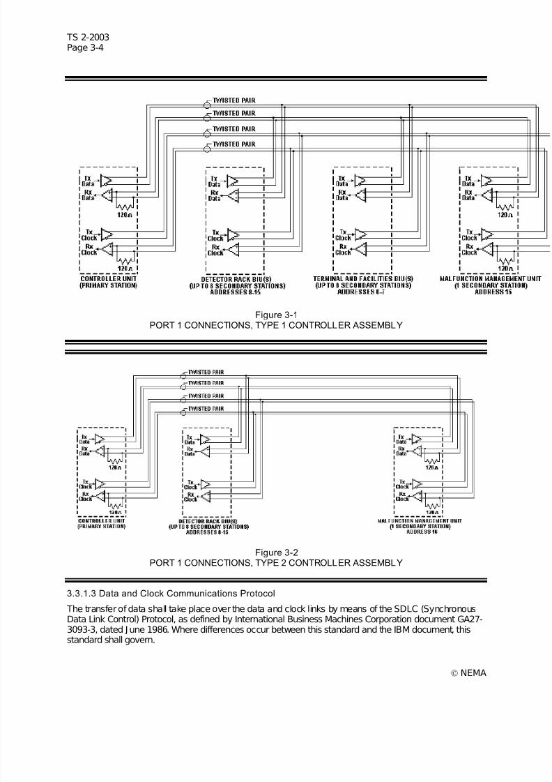
7/30/2019 NEMA TS2-2003- Traffic Controller Assemb
http://slidepdf.com/reader/full/nema-ts2-2003-traffic-controller-assemb 68/246
TS 2-2003Page 3-4
© NEMA
Figure 3-1PORT 1 CONNECTIONS, TYPE 1 CONTROLLER ASSEMBLY
Figure 3-2PORT 1 CONNECTIONS, TYPE 2 CONTROLLER ASSEMBLY
3.3.1.3 Data and Clock Communications Protocol
The transfer of data shall take place over the data and clock links by means of the SDLC (SynchronousData Link Control) Protocol, as defined by International Business Machines Corporation document GA27-3093-3, dated June 1986. Where differences occur between this standard and the IBM document, thisstandard shall govern.
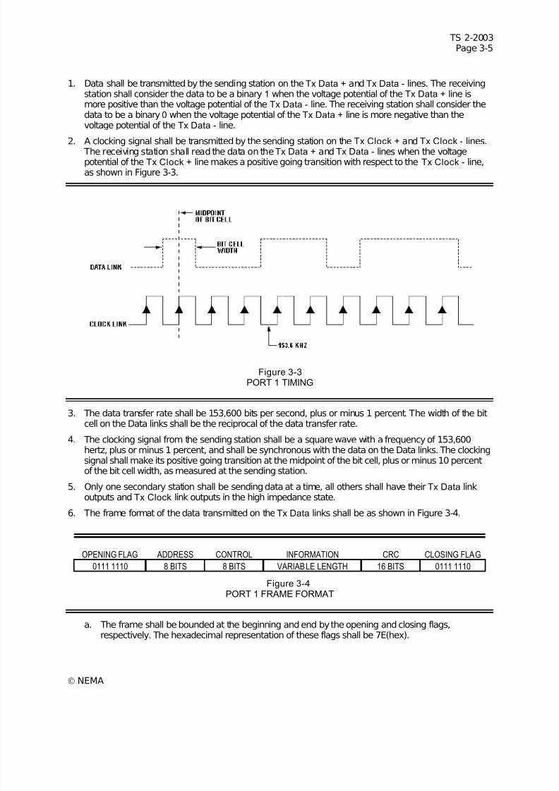
7/30/2019 NEMA TS2-2003- Traffic Controller Assemb
http://slidepdf.com/reader/full/nema-ts2-2003-traffic-controller-assemb 69/246
TS 2-2003Page 3-5
© NEMA
1. Data shall be transmitted by the sending station on the Tx Data + and Tx Data - lines. The receivingstation shall consider the data to be a binary 1 when the voltage potential of the Tx Data + line ismore positive than the voltage potential of the Tx Data - line. The receiving station shall consider thedata to be a binary 0 when the voltage potential of the Tx Data + line is more negative than thevoltage potential of the Tx Data - line.
2. A clocking signal shall be transmitted by the sending station on the Tx Clock + and Tx Clock - lines. The receiving station shall read the data on theTx Data + and Tx Data - lines when the voltagepotential of the Tx Clock + line makes a positive going transition with respect to the Tx Clock - line,as shown in Figure 3-3.
Figure 3-3PORT 1 TIMING
3. The data transfer rate shall be 153,600 bits per second, plus or minus 1 percent. The width of the bitcell on the Data links shall be the reciprocal of the data transfer rate.
4. The clocking signal from the sending station shall be a square wave with a frequency of 153,600hertz, plus or minus 1 percent, and shall be synchronous with the data on the Data links. The clockingsignal shall make its positive going transition at the midpoint of the bit cell, plus or minus 10 percentof the bit cell width, as measured at the sending station.
5. Only one secondary station shall be sending data at a time, all others shall have their Tx Data linkoutputs and Tx Clock link outputs in the high impedance state.
6. The frame format of the data transmitted on the Tx Data links shall be as shown in Figure 3-4.
OPENING FLAG ADDRESS CONTROL INFORMATION CRC CLOSING FLAG0111 1110 8 BITS 8 BITS VARIABLE LENGTH 16 BITS 0111 1110
Figure 3-4PORT 1 FRAME FORMAT
a. The frame shall be bounded at the beginning and end by the opening and closing flags,respectively. The hexadecimal representation of these flags shall be 7E(hex).
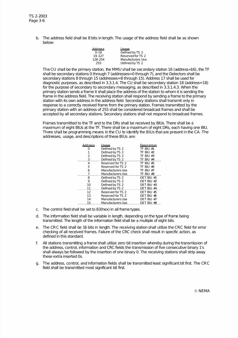
7/30/2019 NEMA TS2-2003- Traffic Controller Assemb
http://slidepdf.com/reader/full/nema-ts2-2003-traffic-controller-assemb 70/246
TS 2-2003Page 3-6
© NEMA
b. The address field shall be 8 bits in length. The usage of the address field shall be as shownbelow:
Address Usage0–18 Defined by TS 2
19–127 Reserved for TS 2
128–254 Manufacturers Use255 Defined by TS 2
The CU shall be the primary station, the MMU shall be secondary station 16 (address=16), the TFshall be secondary stations 0 through 7 (addresses=0 through 7), and the Detectors shall besecondary stations 8 through 15 (addresses=8 through 15). Address 17 shall be used fordiagnostic purposes, as described in 3.3.1.4. The CU shall be secondary station 18 (address=18)for the purpose of secondary to secondary messaging, as described in 3.3.1.4.3. When theprimary station sends a frame it shall place the address of the station to whom it is sending theframe in the address field. The receiving station shall respond by sending a frame to the primarystation with its own address in the address field. Secondary stations shall transmit only inresponse to a correctly received frame from the primary station. Frames transmitted by theprimary station with an address of 255 shall be considered broadcast frames and shall beaccepted by all secondary stations. Secondary stations shall not respond to broadcast frames.
Frames transmitted to the TF and to the DRs shall be received by BIUs. There shall be amaximum of eight BIUs at the TF. There shall be a maximum of eight DRs, each having one BIU. There shall be programming means in the CU to identify the BIUs that are present in the CA. Theaddresses, usage, and descriptions of these BIUs are:
Add ress Usage Descr iption0 Defined by TS 2 TF BIU #11 Defined by TS 2 TF BIU #22 Defined by TS 2 TF BIU #33 Defined by TS 2 TF BIU #44 Reserved for TS 2 TF BIU #55 Reserved for TS 2 TF BIU #66 Manufacturers Use TF BIU #77 Manufacturers Use TF BIU #8
8 Defined by TS 2 DET BIU #19 Defined by TS 2 DET BIU #210 Defined by TS 2 DET BIU #311 Defined by TS 2 DET BIU #412 Reserved for TS 2 DET BIU #513 Reserved for TS 2 DET BIU #614 Manufacturers Use DET BIU #715 Manufacturers Use DET BIU #8
c. The control field shall be set to 83(hex) in all frame types.
d. The information field shall be variable in length, depending on the type of frame beingtransmitted. The length of the information field shall be a multiple of eight bits.
e. The CRC field shall be 16 bits in length. The receiving station shall utilize the CRC field for errorchecking of all received frames. Failure of the CRC check shall result in specific action, as
defined in this standard.f. All stations transmitting a frame shall utilize zero bit insertion whereby during the transmission of
the address, control, information and CRC fields the transmission of five consecutive binary 1'sshall always be followed by the insertion of one binary 0. The receiving stations shall strip awaythese extra inserted 0s.
g. The address, control, and information fields shall be transmitted least significant bit first. The CRCfield shall be transmitted most significant bit first.
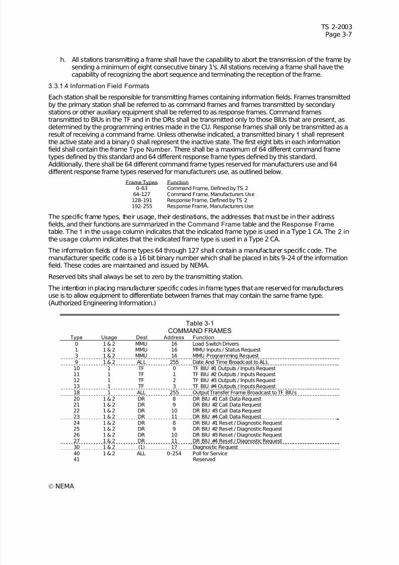
7/30/2019 NEMA TS2-2003- Traffic Controller Assemb
http://slidepdf.com/reader/full/nema-ts2-2003-traffic-controller-assemb 71/246
TS 2-2003Page 3-7
© NEMA
h. All stations transmitting a frame shall have the capability to abort the transmission of the frame bysending a minimum of eight consecutive binary 1's. All stations receiving a frame shall have thecapability of recognizing the abort sequence and terminating the reception of the frame.
3.3.1.4 Information Field Formats
Each station shall be responsible for transmitting frames containing information fields. Frames transmittedby the primary station shall be referred to as command frames and frames transmitted by secondarystations or other auxiliary equipment shall be referred to as response frames. Command framestransmitted to BIUs in the TF and in the DRs shall be transmitted only to those BIUs that are present, asdetermined by the programming entries made in the CU. Response frames shall only be transmitted as aresult of receiving a command frame. Unless otherwise indicated, a transmitted binary 1 shall representthe active state and a binary 0 shall represent the inactive state. The first eight bits in each informationfield shall contain the frame Type Number . There shall be a maximum of 64 different command frametypes defined by this standard and 64 different response frame types defined by this standard.Additionally, there shall be 64 different command frame types reserved for manufacturers use and 64different response frame types reserved for manufacturers use, as outlined below.
Frame Types Function0–63 Command Frame, Defined by TS 2
64–127 Command Frame, Manufacturers Use128–191 Response Frame, Defined by TS 2192–255 Response Frame, Manufacturers Use
The specific frame types, their usage, their destinations, the addresses that must be in their addressfields, and their functions are summarized in the Command Frame table and the Response Frame table. The 1 in the usage column indicates that the indicated frame type is used in a Type 1 CA. The 2 inthe usage column indicates that the indicated frame type is used in a Type 2 CA.
The information fields of frame types 64 through 127 shall contain a manufacturer specific code. Themanufacturer specific code is a 16 bit binary number which shall be placed in bits 9–24 of the informationfield. These codes are maintained and issued by NEMA.
Reserved bits shall always be set to zero by the transmitting station.
The intention in placing manufacturer specific codes in frame types that are reserved for manufacturers
use is to allow equipment to differentiate between frames that may contain the same frame type.(Authorized Engineering Information.)
Table 3-1COMMAND FRAMES
Type Usage Dest Address Function
0 1 & 2 MMU 16 Load Switch Drivers1 1 & 2 MMU 16 MMU Inputs / Status Request3 1 & 2 MMU 16 MMU Programming Request9 1 & 2 ALL 255 Date And Time Broadcast to ALL10 1 TF 0 TF BIU #1 Outputs / Inputs Request11 1 TF 1 TF BIU #2 Outputs / Inputs Request12 1 TF 2 TF BIU #3 Outputs / Inputs Request13 1 TF 3 TF BIU #4 Outputs / Inputs Request18 1 ALL 255 Output Transfer Frame Broadcast to TF BIUs20 1 & 2 DR 8 DR BIU #1 Call Data Request21 1 & 2 DR 9 DR BIU #2 Call Data Request22 1 & 2 DR 10 DR BIU #3 Call Data Request23 1 & 2 DR 11 DR BIU #4 Call Data Request24 1 & 2 DR 8 DR BIU #1 Reset / Diagnostic Request25 1 & 2 DR 9 DR BIU #2 Reset / Diagnostic Request26 1 & 2 DR 10 DR BIU #3 Reset / Diagnostic Request27 1 & 2 DR 11 DR BIU #4 Reset / Diagnostic Request30 1 & 2 (1) 17 Diagnostic Request40 1 & 2 ALL 0–254 Poll for Service41 Reserved
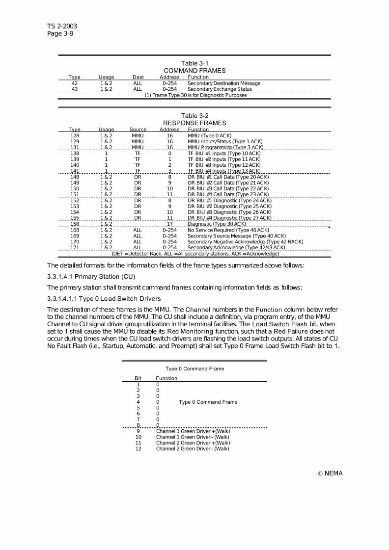
7/30/2019 NEMA TS2-2003- Traffic Controller Assemb
http://slidepdf.com/reader/full/nema-ts2-2003-traffic-controller-assemb 72/246
TS 2-2003Page 3-8
© NEMA
Table 3-1COMMAND FRAMES
Type Usage Dest Address Function
42 1 & 2 ALL 0–254 Secondary Destination Message43 1 & 2 ALL 0–254 Secondary Exchange Status
(1) Frame Type 30 is for Diagnostic Purposes
Table 3-2RESPONSE FRAMES
Type Usage Source Address Function
128 1 & 2 MMU 16 MMU (Type 0 ACK)129 1 & 2 MMU 16 MMU Inputs/Status (Type 1 ACK)131 1 & 2 MMU 16 MMU Programming (Type 3 ACK)138 1 TF 0 TF BIU #1 Inputs (Type 10 ACK)139 1 TF 1 TF BIU #2 Inputs (Type 11 ACK)140 1 TF 2 TF BIU #3 Inputs (Type 12 ACK)141 1 TF 3 TF BIU #4 Inputs (Type 13 ACK)148 1 & 2 DR 8 DR BIU #1 Call Data (Type 20 ACK)149 1 & 2 DR 9 DR BIU #2 Call Data (Type 21 ACK)150 1 & 2 DR 10 DR BIU #3 Call Data (Type 22 ACK)151 1 & 2 DR 11 DR BIU #4 Call Data (Type 23 ACK)152 1 & 2 DR 8 DR BIU #1 Diagnostic (Type 24 ACK)153 1 & 2 DR 9 DR BIU #2 Diagnostic (Type 25 ACK)154 1 & 2 DR 10 DR BIU #3 Diagnostic (Type 26 ACK)155 1 & 2 DR 11 DR BIU #4 Diagnostic (Type 27 ACK)158 1 & 2 17 Diagnostic (Type 30 ACK)168 1 & 2 ALL 0–254 No Service Required (Type 40 ACK)169 1 & 2 ALL 0–254 Secondary Source Message (Type 40 ACK)170 1 & 2 ALL 0–254 Secondary Negative Acknowledge (Type 42 NACK)171 1 & 2 ALL 0–254 Secondary Acknowledge (Type 42/43 ACK)
(DET =Detector Rack, ALL =All secondary stations, ACK =Acknowledge)
The detailed formats for the information fields of the frame types summarized above follows:
3.3.1.4.1 Primary Station (CU)
The primary station shall transmit command frames containing information fields as follows:3.3.1.4.1.1 Type 0 Load Switch Drivers
The destination of these frames is the MMU. The Channel numbers in the Function column below referto the channel numbers of the MMU. The CU shall include a definition, via program entry, of the MMUChannel to CU signal driver group utilization in the terminal facilities. The Load Switch Flash bit, whenset to 1 shall cause the MMU to disable its Red Monitor ing function, such that a Red Failure does notoccur during times when the CU load switch drivers are flashing the load switch outputs. All states of CUNo Fault Flash (i.e., Startup, Automatic, and Preempt) shall set Type 0 Frame Load Switch Flash bit to 1.
Type 0 Command Frame
Bit Function
1 02 03 04 0 Type 0 Command Frame 5 06 07 08 09 Channel 1 Green Driver +(Walk)10 Channel 1 Green Driver - (Walk)11 Channel 2 Green Driver +(Walk)12 Channel 2 Green Driver - (Walk)
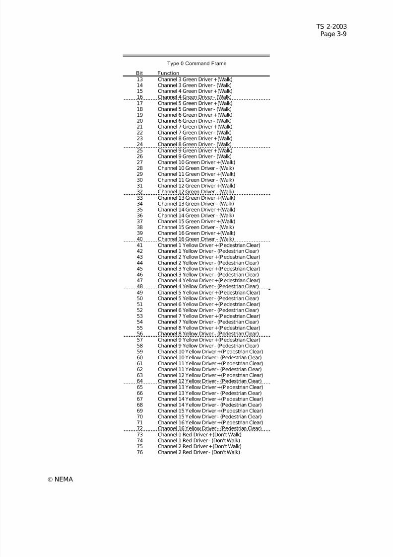
7/30/2019 NEMA TS2-2003- Traffic Controller Assemb
http://slidepdf.com/reader/full/nema-ts2-2003-traffic-controller-assemb 73/246
TS 2-2003Page 3-9
© NEMA
Type 0 Command Frame
Bit Function
13 Channel 3 Green Driver +(Walk)14 Channel 3 Green Driver - (Walk)15 Channel 4 Green Driver +(Walk)
16 Channel 4 Green Driver - (Walk)17 Channel 5 Green Driver +(Walk)18 Channel 5 Green Driver - (Walk)19 Channel 6 Green Driver +(Walk)20 Channel 6 Green Driver - (Walk)21 Channel 7 Green Driver +(Walk)22 Channel 7 Green Driver - (Walk)23 Channel 8 Green Driver +(Walk)24 Channel 8 Green Driver - (Walk)25 Channel 9 Green Driver +(Walk)26 Channel 9 Green Driver - (Walk)27 Channel 10 Green Driver +(Walk)28 Channel 10 Green Driver - (Walk)29 Channel 11 Green Driver +(Walk)30 Channel 11 Green Driver - (Walk)31 Channel 12 Green Driver +(Walk)32 Channel 12 Green Driver - (Walk)33 Channel 13 Green Driver +(Walk)34 Channel 13 Green Driver - (Walk)35 Channel 14 Green Driver +(Walk)36 Channel 14 Green Driver - (Walk)37 Channel 15 Green Driver +(Walk)38 Channel 15 Green Driver - (Walk)39 Channel 16 Green Driver +(Walk)40 Channel 16 Green Driver - (Walk)41 Channel 1 Yellow Driver +(Pedestrian Clear)42 Channel 1 Yellow Driver - (Pedestrian Clear)43 Channel 2 Yellow Driver +(Pedestrian Clear)44 Channel 2 Yellow Driver - (Pedestrian Clear)45 Channel 3 Yellow Driver +(Pedestrian Clear)46 Channel 3 Yellow Driver - (Pedestrian Clear)47 Channel 4 Yellow Driver +(Pedestrian Clear)48 Channel 4 Yellow Driver - (Pedestrian Clear)
49 Channel 5 Yellow Driver +(Pedestrian Clear)50 Channel 5 Yellow Driver - (Pedestrian Clear)51 Channel 6 Yellow Driver +(Pedestrian Clear)52 Channel 6 Yellow Driver - (Pedestrian Clear)53 Channel 7 Yellow Driver +(Pedestrian Clear)54 Channel 7 Yellow Driver - (Pedestrian Clear)55 Channel 8 Yellow Driver +(Pedestrian Clear)56 Channel 8 Yellow Driver - (Pedestrian Clear)57 Channel 9 Yellow Driver +(Pedestrian Clear)58 Channel 9 Yellow Driver - (Pedestrian Clear)59 Channel 10 Yellow Driver +(Pedestrian Clear)60 Channel 10 Yellow Driver - (Pedestrian Clear)61 Channel 11 Yellow Driver +(Pedestrian Clear)62 Channel 11 Yellow Driver - (Pedestrian Clear)63 Channel 12 Yellow Driver +(Pedestrian Clear)64 Channel 12 Yellow Driver - (Pedestrian Clear)65 Channel 13 Yellow Driver +(Pedestrian Clear)66 Channel 13 Yellow Driver - (Pedestrian Clear)67 Channel 14 Yellow Driver +(Pedestrian Clear)68 Channel 14 Yellow Driver - (Pedestrian Clear)69 Channel 15 Yellow Driver +(Pedestrian Clear)70 Channel 15 Yellow Driver - (Pedestrian Clear)71 Channel 16 Yellow Driver +(Pedestrian Clear)72 Channel 16 Yellow Driver - (Pedestrian Clear)73 Channel 1 Red Driver +(Don’t Walk)74 Channel 1 Red Driver - (Don’t Walk)75 Channel 2 Red Driver +(Don’t Walk)76 Channel 2 Red Driver - (Don’t Walk)
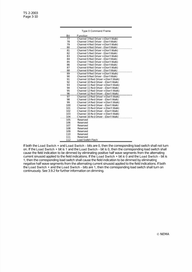
7/30/2019 NEMA TS2-2003- Traffic Controller Assemb
http://slidepdf.com/reader/full/nema-ts2-2003-traffic-controller-assemb 74/246
TS 2-2003Page 3-10
© NEMA
Type 0 Command Frame
Bit Function
77 Channel 3 Red Driver +(Don’t Walk)78 Channel 3 Red Driver - (Don’t Walk)79 Channel 4 Red Driver +(Don’t Walk)
80 Channel 4 Red Driver - (Don’t Walk)81 Channel 5 Red Driver +(Don’t Walk)82 Channel 5 Red Driver - (Don’t Walk)83 Channel 6 Red Driver +(Don’t Walk)84 Channel 6 Red Driver - (Don’t Walk)85 Channel 7 Red Driver +(Don’t Walk)86 Channel 7 Red Driver - (Don’t Walk)87 Channel 8 Red Driver +(Don’t Walk)88 Channel 8 Red Driver - (Don’t Walk)89 Channel 9 Red Driver +(Don’t Walk)90 Channel 9 Red Driver - (Don’t Walk)91 Channel 10 Red Driver +(Don’t Walk)92 Channel 10 Red Driver - (Don’t Walk)93 Channel 11 Red Driver +(Don’t Walk)94 Channel 11 Red Driver - (Don’t Walk)95 Channel 12 Red Driver +(Don’t Walk)96 Channel 12 Red Driver - (Don’t Walk)97 Channel 13 Red Driver +(Don’t Walk)98 Channel 13 Red Driver - (Don’t Walk)99 Channel 14 Red Driver +(Don’t Walk)100 Channel 14 Red Driver - (Don’t Walk)101 Channel 15 Red Driver +(Don’t Walk)102 Channel 15 Red Driver - (Don’t Walk)103 Channel 16 Red Driver +(Don’t Walk)104 Channel 16 Red Driver - (Don’t Walk)105 Reserved106 Reserved107 Reserved108 Reserved109 Reserved110 Reserved111 Reserved112 Load Switch Flash
If both the Load Switch + and Load Switch - bits are 0, then the corresponding load switch shall not turnon. If the Load Switch + bit is 1 and the Load Switch - bit is 0, then the corresponding load switch shallcause the field indication to be dimmed by eliminating positive half wave segments from the alternatingcurrent sinusoid applied to the field indications. If the Load Switch + bit is 0 and the Load Switch - bit is1, then the corresponding load switch shall cause the field indication to be dimmed by eliminatingnegative half wave segments from the alternating current sinusoid applied to the field indications. If boththe Load Switch + and the Load Switch - bits are 1, then the corresponding load switch shall turn oncontinuously. See 3.9.2 for further information on dimming.
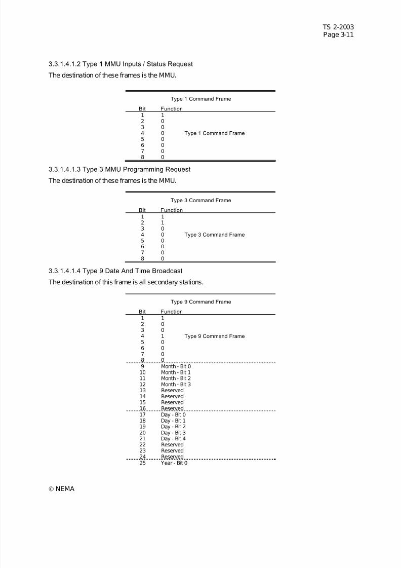
7/30/2019 NEMA TS2-2003- Traffic Controller Assemb
http://slidepdf.com/reader/full/nema-ts2-2003-traffic-controller-assemb 75/246
TS 2-2003Page 3-11
© NEMA
3.3.1.4.1.2 Type 1 MMU Inputs / Status Request
The destination of these frames is the MMU.
Type 1 Command Frame
Bit Function
1 12 03 04 0 Type 1 Command Frame 5 06 07 08 0
3.3.1.4.1.3 Type 3 MMU Programming Request
The destination of these frames is the MMU.
Type 3 Command Frame
Bit Function
1 12 13 04 0 Type 3 Command Frame 5 06 07 08 0
3.3.1.4.1.4 Type 9 Date And Time Broadcast
The destination of this frame is all secondary stations.
Type 9 Command Frame
Bit Function
1 12 03 04 1 Type 9 Command Frame 5 06 07 08 09 Month - Bit 010 Month - Bit 111 Month - Bit 212 Month - Bit 313 Reserved
14 Reserved15 Reserved16 Reserved17 Day - Bit 018 Day - Bit 119 Day - Bit 220 Day - Bit 321 Day - Bit 422 Reserved23 Reserved24 Reserved25 Year - Bit 0
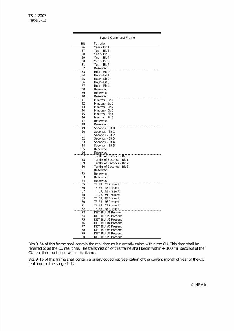
7/30/2019 NEMA TS2-2003- Traffic Controller Assemb
http://slidepdf.com/reader/full/nema-ts2-2003-traffic-controller-assemb 76/246
TS 2-2003Page 3-12
© NEMA
Type 9 Command Frame
Bit Function
26 Year - Bit 127 Year - Bit 228 Year - Bit 3
29 Year - Bit 430 Year - Bit 531 Year - Bit 632 Reserved33 Hour - Bit 034 Hour - Bit 135 Hour - Bit 236 Hour - Bit 337 Hour - Bit 438 Reserved39 Reserved40 Reserved41 Minutes - Bit 042 Minutes - Bit 143 Minutes - Bit 244 Minutes - Bit 345 Minutes - Bit 446 Minutes - Bit 547 Reserved48 Reserved49 Seconds - Bit 050 Seconds - Bit 151 Seconds - Bit 252 Seconds - Bit 353 Seconds - Bit 454 Seconds - Bit 555 Reserved56 Reserved57 Tenths of Seconds - Bit 058 Tenths of Seconds - Bit 159 Tenths of Seconds - Bit 260 Tenths of Seconds - Bit 361 Reserved
62 Reserved63 Reserved64 Reserved65 TF BIU #1 Present66 TF BIU #2 Present67 TF BIU #3 Present68 TF BIU #4 Present69 TF BIU #5 Present70 TF BIU #6 Present71 TF BIU #7 Present72 TF BIU #8 Present73 DET BIU #1 Present74 DET BIU #2 Present75 DET BIU #3 Present76 DET BIU #4 Present77 DET BIU #5 Present78 DET BIU #6 Present79 DET BIU #7 Present80 DET BIU #8 Present
Bits 9–64 of this frame shall contain the real time as it currently exists within the CU. This time shall bereferred to as the CU real time. The transmission of this frame shall begin within + 100 milliseconds of theCU real time contained within the frame.
Bits 9–16 of this frame shall contain a binary coded representation of the current month of year of the CUreal time, in the range 1–12.
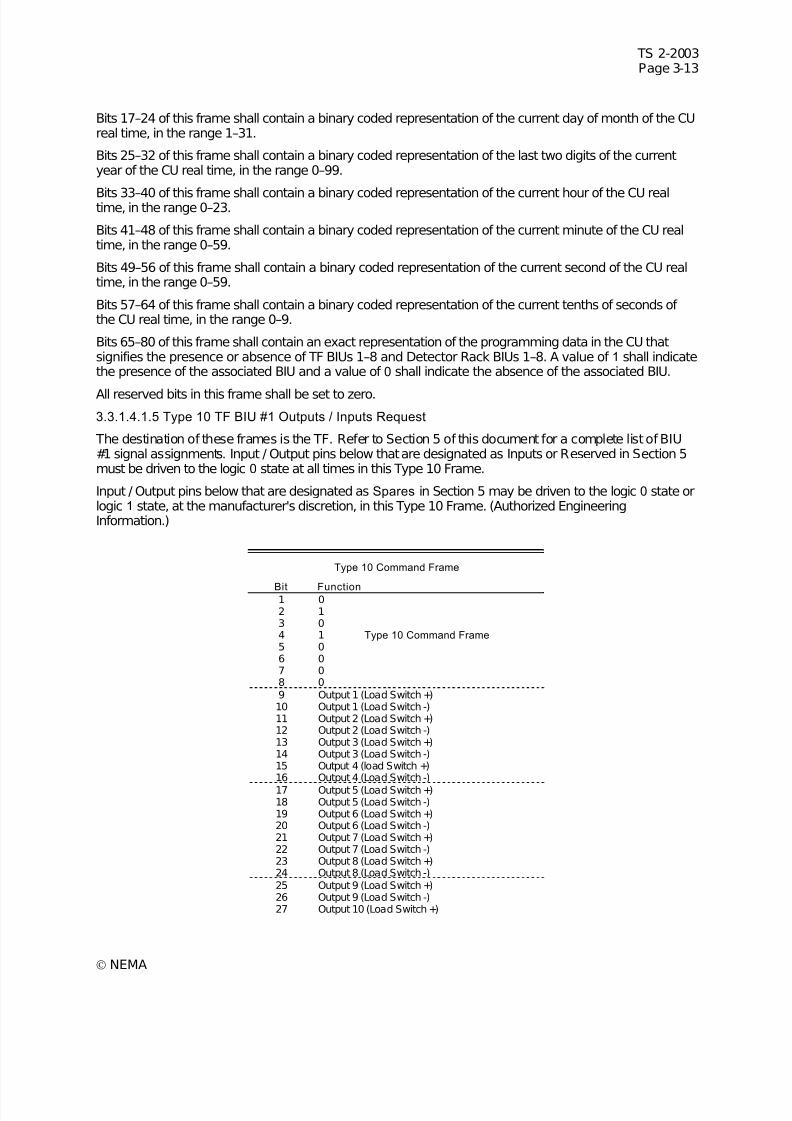
7/30/2019 NEMA TS2-2003- Traffic Controller Assemb
http://slidepdf.com/reader/full/nema-ts2-2003-traffic-controller-assemb 77/246
TS 2-2003Page 3-13
© NEMA
Bits 17–24 of this frame shall contain a binary coded representation of the current day of month of the CUreal time, in the range 1–31.
Bits 25–32 of this frame shall contain a binary coded representation of the last two digits of the currentyear of the CU real time, in the range 0–99.
Bits 33–40 of this frame shall contain a binary coded representation of the current hour of the CU realtime, in the range 0–23.
Bits 41–48 of this frame shall contain a binary coded representation of the current minute of the CU realtime, in the range 0–59.
Bits 49–56 of this frame shall contain a binary coded representation of the current second of the CU realtime, in the range 0–59.
Bits 57–64 of this frame shall contain a binary coded representation of the current tenths of seconds of the CU real time, in the range 0–9.
Bits 65–80 of this frame shall contain an exact representation of the programming data in the CU thatsignifies the presence or absence of TF BIUs 1–8 and Detector Rack BIUs 1–8. A value of 1 shall indicatethe presence of the associated BIU and a value of 0 shall indicate the absence of the associated BIU.
All reserved bits in this frame shall be set to zero.
3.3.1.4.1.5 Type 10 TF BIU #1 Outputs / Inputs Request
The destination of these frames is the TF. Refer to Section 5 of this document for a complete list of BIU#1 signal assignments. Input / Output pins below that are designated as Inputs or Reserved in Section 5must be driven to the logic 0 state at all times in this Type 10 Frame.
Input / Output pins below that are designated as Spares in Section 5 may be driven to the logic 0 state orlogic 1 state, at the manufacturer's discretion, in this Type 10 Frame. (Authorized EngineeringInformation.)
Type 10 Command Frame
Bit Function1 02 13 04 1 Type 10 Command Frame 5 06 07 08 09 Output 1 (Load Switch +)10 Output 1 (Load Switch -)11 Output 2 (Load Switch +)12 Output 2 (Load Switch -)13 Output 3 (Load Switch +)14 Output 3 (Load Switch -)15 Output 4 (load Switch +)16 Output 4 (Load Switch -)17 Output 5 (Load Switch +)18 Output 5 (Load Switch -)19 Output 6 (Load Switch +)20 Output 6 (Load Switch -)21 Output 7 (Load Switch +)22 Output 7 (Load Switch -)23 Output 8 (Load Switch +)24 Output 8 (Load Switch -)25 Output 9 (Load Switch +)26 Output 9 (Load Switch -)27 Output 10 (Load Switch +)
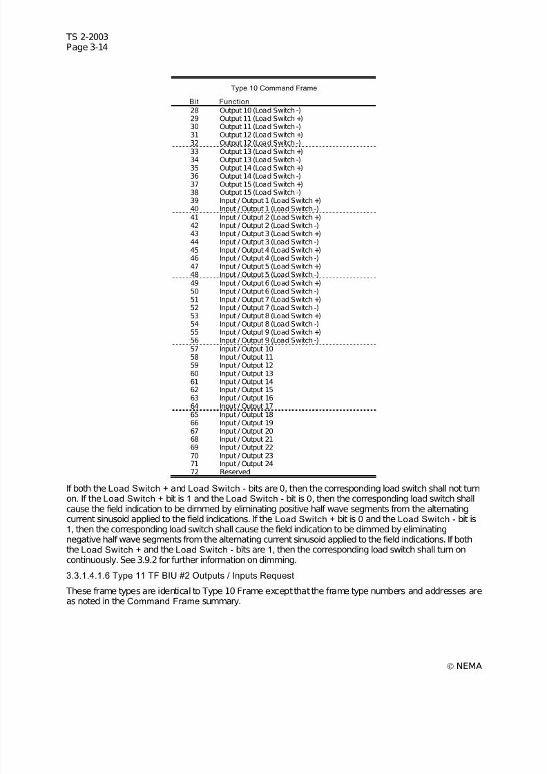
7/30/2019 NEMA TS2-2003- Traffic Controller Assemb
http://slidepdf.com/reader/full/nema-ts2-2003-traffic-controller-assemb 78/246
TS 2-2003Page 3-14
© NEMA
Type 10 Command Frame
Bit Function
28 Output 10 (Load Switch -)29 Output 11 (Load Switch +)30 Output 11 (Load Switch -)
31 Output 12 (Load Switch +)32 Output 12 (Load Switch -)33 Output 13 (Load Switch +)34 Output 13 (Load Switch -)35 Output 14 (Load Switch +)36 Output 14 (Load Switch -)37 Output 15 (Load Switch +)38 Output 15 (Load Switch -)39 Input / Output 1 (Load Switch +)40 Input / Output 1 (Load Switch -)41 Input / Output 2 (Load Switch +)42 Input / Output 2 (Load Switch -)43 Input / Output 3 (Load Switch +)44 Input / Output 3 (Load Switch -)45 Input / Output 4 (Load Switch +)46 Input / Output 4 (Load Switch -)47 Input / Output 5 (Load Switch +)48 Input / Output 5 (Load Switch -)49 Input / Output 6 (Load Switch +)50 Input / Output 6 (Load Switch -)51 Input / Output 7 (Load Switch +)52 Input / Output 7 (Load Switch -)53 Input / Output 8 (Load Switch +)54 Input / Output 8 (Load Switch -)55 Input / Output 9 (Load Switch +)56 Input / Output 9 (Load Switch -)57 Input / Output 1058 Input / Output 1159 Input / Output 1260 Input / Output 1361 Input / Output 1462 Input / Output 1563 Input / Output 16
64 Input / Output 1765 Input / Output 1866 Input / Output 1967 Input / Output 2068 Input / Output 2169 Input / Output 2270 Input / Output 2371 Input / Output 2472 Reserved
If both the Load Switch + and Load Switch - bits are 0, then the corresponding load switch shall not turnon. If the Load Switch + bit is 1 and the Load Switch - bit is 0, then the corresponding load switch shallcause the field indication to be dimmed by eliminating positive half wave segments from the alternatingcurrent sinusoid applied to the field indications. If the Load Switch + bit is 0 and the Load Switch - bit is1, then the corresponding load switch shall cause the field indication to be dimmed by eliminating
negative half wave segments from the alternating current sinusoid applied to the field indications. If boththe Load Switch + and the Load Switch - bits are 1, then the corresponding load switch shall turn oncontinuously. See 3.9.2 for further information on dimming.
3.3.1.4.1.6 Type 11 TF BIU #2 Outputs / Inputs Request
These frame types are identical to Type 10 Frame except that the frame type numbers and addresses areas noted in the Command Frame summary.
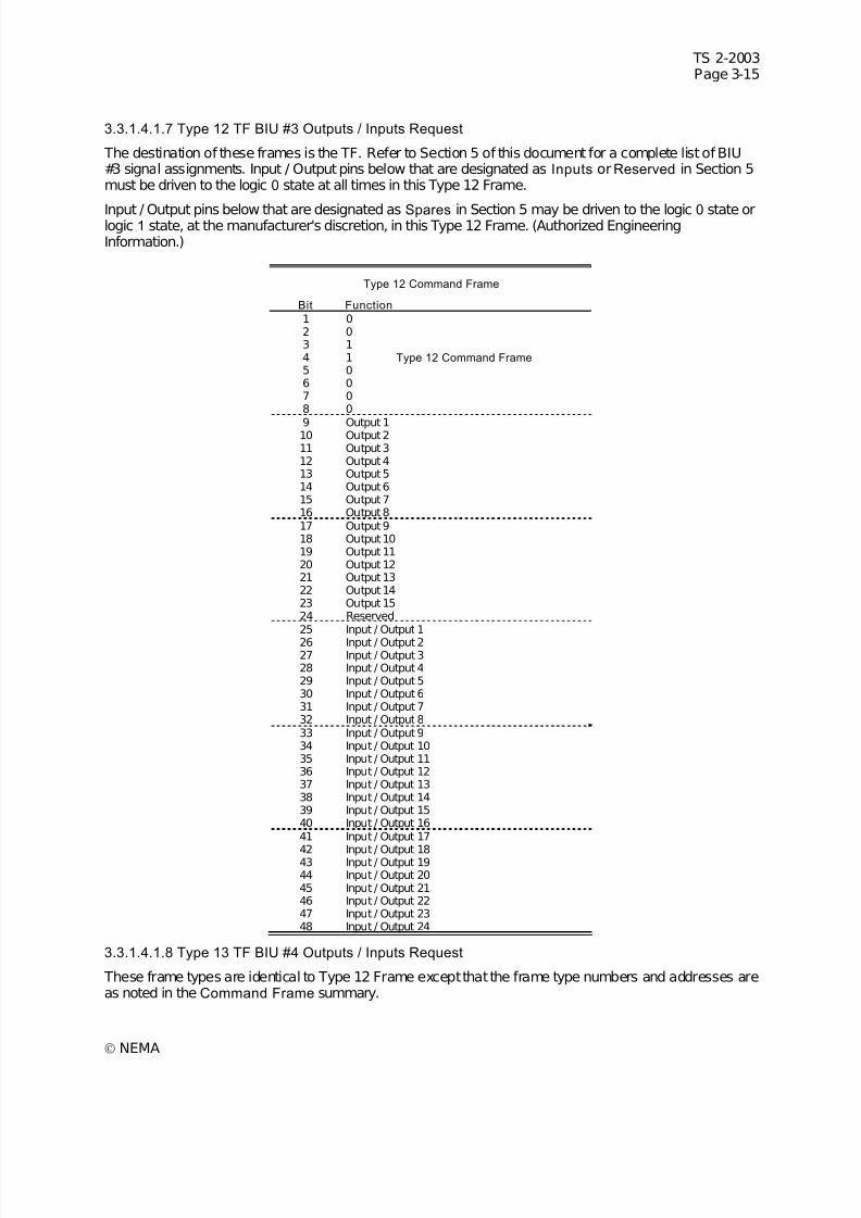
7/30/2019 NEMA TS2-2003- Traffic Controller Assemb
http://slidepdf.com/reader/full/nema-ts2-2003-traffic-controller-assemb 79/246
TS 2-2003Page 3-15
© NEMA
3.3.1.4.1.7 Type 12 TF BIU #3 Outputs / Inputs Request
The destination of these frames is the TF. Refer to Section 5 of this document for a complete list of BIU#3 signal assignments. Input / Output pins below that are designated as Inputs or Reserved in Section 5must be driven to the logic 0 state at all times in this Type 12 Frame.
Input / Output pins below that are designated as Spares in Section 5 may be driven to the logic 0 state orlogic 1 state, at the manufacturer's discretion, in this Type 12 Frame. (Authorized EngineeringInformation.)
Type 12 Command Frame
Bit Function
1 02 03 14 1 Type 12 Command Frame 5 06 07 08 0
9 Output 110 Output 211 Output 312 Output 413 Output 514 Output 615 Output 716 Output 817 Output 918 Output 1019 Output 1120 Output 1221 Output 1322 Output 1423 Output 1524 Reserved25 Input / Output 1
26 Input / Output 227 Input / Output 328 Input / Output 429 Input / Output 530 Input / Output 631 Input / Output 732 Input / Output 833 Input / Output 934 Input / Output 1035 Input / Output 1136 Input / Output 1237 Input / Output 1338 Input / Output 1439 Input / Output 1540 Input / Output 1641 Input / Output 17
42 Input / Output 1843 Input / Output 1944 Input / Output 2045 Input / Output 2146 Input / Output 2247 Input / Output 2348 Input / Output 24
3.3.1.4.1.8 Type 13 TF BIU #4 Outputs / Inputs Request
These frame types are identical to Type 12 Frame except that the frame type numbers and addresses areas noted in the Command Frame summary.
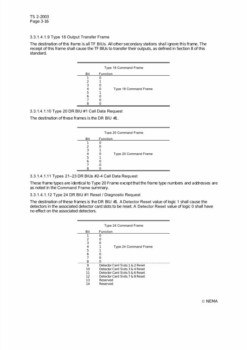
7/30/2019 NEMA TS2-2003- Traffic Controller Assemb
http://slidepdf.com/reader/full/nema-ts2-2003-traffic-controller-assemb 80/246
TS 2-2003Page 3-16
© NEMA
3.3.1.4.1.9 Type 18 Output Transfer Frame
The destination of this frame is all TF BIUs. All other secondary stations shall ignore this frame. Thereceipt of this frame shall cause the TF BIUs to transfer their outputs, as defined in Section 8 of thisstandard.
Type 18 Command Frame
Bit Function
1 02 13 04 0 Type 18 Command Frame 5 16 07 08 0
3.3.1.4.1.10 Type 20 DR BIU #1 Call Data Request
The destination of these frames is the DR BIU #1.
Type 20 Command Frame
Bit Function
1 02 03 14 0 Type 20 Command Frame 5 16 07 08 0
3.3.1.4.1.11 Types 21–23 DR BIUs #2-4 Call Data Request
These frame types are identical to Type 20 Frame except that the frame type numbers and addresses areas noted in the Command Frame summary.
3.3.1.4.1.12 Type 24 DR BIU #1 Reset / Diagnostic Request
The destination of these frames is the DR BIU #1. A Detector Reset value of logic 1 shall cause thedetectors in the associated detector card slots to be reset. A Detector Reset value of logic 0 shall haveno effect on the associated detectors.
Type 24 Command Frame
Bit Function
1 02 03 04 1 Type 24 Command Frame 5 16 07 08 09 Detector Card Slots 1 & 2 Reset10 Detector Card Slots 3 & 4 Reset11 Detector Card Slots 5 & 6 Reset12 Detector Card Slots 7 & 8 Reset13 Reserved14 Reserved
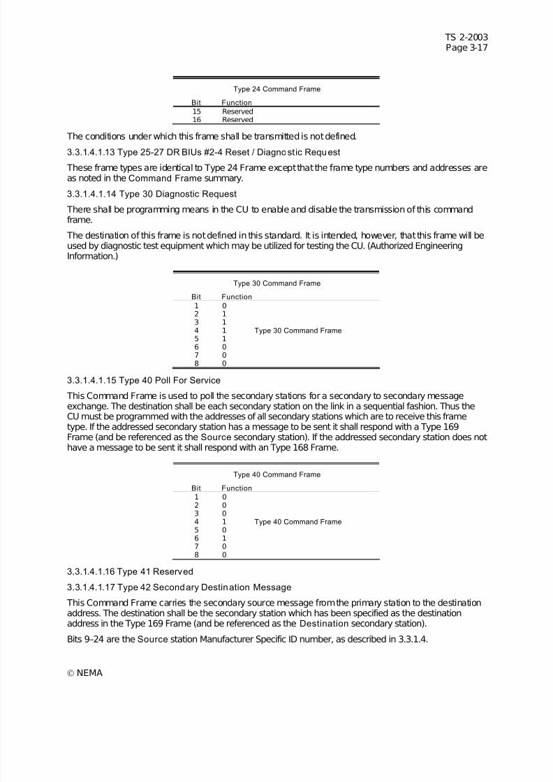
7/30/2019 NEMA TS2-2003- Traffic Controller Assemb
http://slidepdf.com/reader/full/nema-ts2-2003-traffic-controller-assemb 81/246
TS 2-2003Page 3-17
© NEMA
Type 24 Command Frame
Bit Function
15 Reserved16 Reserved
The conditions under which this frame shall be transmitted is not defined.
3.3.1.4.1.13 Type 25-27 DR BIUs #2-4 Reset / Diagnost ic Request
These frame types are identical to Type 24 Frame except that the frame type numbers and addresses areas noted in the Command Frame summary.
3.3.1.4.1.14 Type 30 Diagnostic Request
There shall be programming means in the CU to enable and disable the transmission of this commandframe.
The destination of this frame is not defined in this standard. It is intended, however, that this frame will beused by diagnostic test equipment which may be utilized for testing the CU. (Authorized EngineeringInformation.)
Type 30 Command Frame
Bit Function
1 02 13 14 1 Type 30 Command Frame 5 16 07 08 0
3.3.1.4.1.15 Type 40 Poll For Service
This Command Frame is used to poll the secondary stations for a secondary to secondary message
exchange. The destination shall be each secondary station on the link in a sequential fashion. Thus theCU must be programmed with the addresses of all secondary stations which are to receive this frametype. If the addressed secondary station has a message to be sent it shall respond with a Type 169Frame (and be referenced as the Source secondary station). If the addressed secondary station does nothave a message to be sent it shall respond with an Type 168 Frame.
Type 40 Command Frame
Bit Function
1 02 03 04 1 Type 40 Command Frame 5 06 1
7 08 0
3.3.1.4.1.16 Type 41 Reserved
3.3.1.4.1.17 Type 42 Secondary Destination Message
This Command Frame carries the secondary source message from the primary station to the destinationaddress. The destination shall be the secondary station which has been specified as the destinationaddress in the Type 169 Frame (and be referenced as the Destination secondary station).
Bits 9–24 are the Source station Manufacturer Specific ID number, as described in 3.3.1.4.
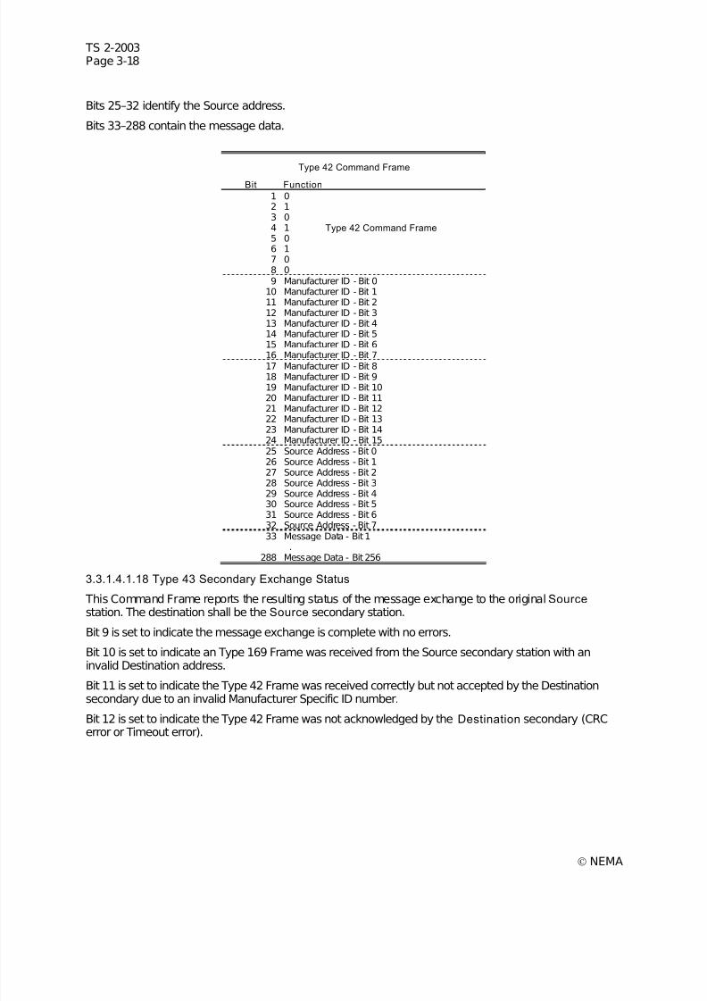
7/30/2019 NEMA TS2-2003- Traffic Controller Assemb
http://slidepdf.com/reader/full/nema-ts2-2003-traffic-controller-assemb 82/246
TS 2-2003Page 3-18
© NEMA
Bits 25–32 identify the Source address.
Bits 33–288 contain the message data.
Type 42 Command Frame
Bit Function
1 02 13 04 1 Type 42 Command Frame 5 06 17 08 09 Manufacturer ID - Bit 0
10 Manufacturer ID - Bit 111 Manufacturer ID - Bit 212 Manufacturer ID - Bit 313 Manufacturer ID - Bit 414 Manufacturer ID - Bit 515 Manufacturer ID - Bit 616 Manufacturer ID - Bit 717 Manufacturer ID - Bit 818 Manufacturer ID - Bit 919 Manufacturer ID - Bit 1020 Manufacturer ID - Bit 1121 Manufacturer ID - Bit 1222 Manufacturer ID - Bit 1323 Manufacturer ID - Bit 1424 Manufacturer ID - Bit 1525 Source Address - Bit 026 Source Address - Bit 127 Source Address - Bit 228 Source Address - Bit 329 Source Address - Bit 430 Source Address - Bit 531 Source Address - Bit 6
32 Source Address - Bit 733 Message Data - Bit 1
.288 Message Data - Bit 256
3.3.1.4.1.18 Type 43 Secondary Exchange Status
This Command Frame reports the resulting status of the message exchange to the original Source station. The destination shall be the Source secondary station.
Bit 9 is set to indicate the message exchange is complete with no errors.
Bit 10 is set to indicate an Type 169 Frame was received from the Source secondary station with aninvalid Destination address.
Bit 11 is set to indicate the Type 42 Frame was received correctly but not accepted by the Destination
secondary due to an invalid Manufacturer Specific ID number.Bit 12 is set to indicate the Type 42 Frame was not acknowledged by the Destination secondary (CRCerror or Timeout error).
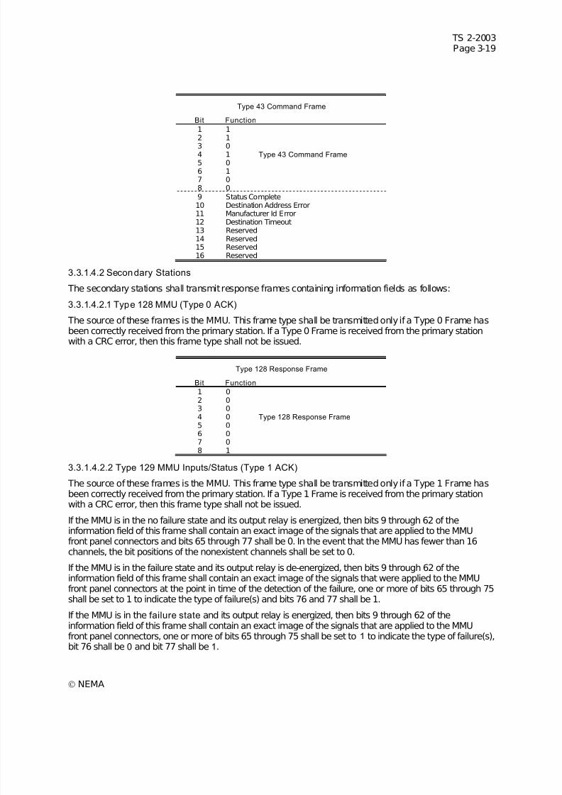
7/30/2019 NEMA TS2-2003- Traffic Controller Assemb
http://slidepdf.com/reader/full/nema-ts2-2003-traffic-controller-assemb 83/246
TS 2-2003Page 3-19
© NEMA
Type 43 Command Frame
Bit Function
1 1
2 13 04 1 Type 43 Command Frame 5 06 17 08 09 Status Complete10 Destination Address Error11 Manufacturer Id Error12 Destination Timeout13 Reserved14 Reserved15 Reserved16 Reserved
3.3.1.4.2 Secondary Stations
The secondary stations shall transmit response frames containing information fields as follows:
3.3.1.4.2.1 Type 128 MMU (Type 0 ACK)
The source of these frames is the MMU. This frame type shall be transmitted only if a Type 0 Frame hasbeen correctly received from the primary station. If a Type 0 Frame is received from the primary stationwith a CRC error, then this frame type shall not be issued.
Type 128 Response Frame
Bit Function
1 02 03 0
4 0 Type 128 Response Frame 5 06 07 08 1
3.3.1.4.2.2 Type 129 MMU Inputs/Status (Type 1 ACK)
The source of these frames is the MMU. This frame type shall be transmitted only if a Type 1 Frame hasbeen correctly received from the primary station. If a Type 1 Frame is received from the primary stationwith a CRC error, then this frame type shall not be issued.
If the MMU is in the no failure state and its output relay is energized, then bits 9 through 62 of theinformation field of this frame shall contain an exact image of the signals that are applied to the MMUfront panel connectors and bits 65 through 77 shall be 0. In the event that the MMU has fewer than 16channels, the bit positions of the nonexistent channels shall be set to 0.
If the MMU is in the failure state and its output relay is de-energized, then bits 9 through 62 of theinformation field of this frame shall contain an exact image of the signals that were applied to the MMUfront panel connectors at the point in time of the detection of the failure, one or more of bits 65 through 75shall be set to 1 to indicate the type of failure(s) and bits 76 and 77 shall be 1.
If the MMU is in the failure state and its output relay is energized, then bits 9 through 62 of theinformation field of this frame shall contain an exact image of the signals that are applied to the MMUfront panel connectors, one or more of bits 65 through 75 shall be set to 1 to indicate the type of failure(s),bit 76 shall be 0 and bit 77 shall be 1.
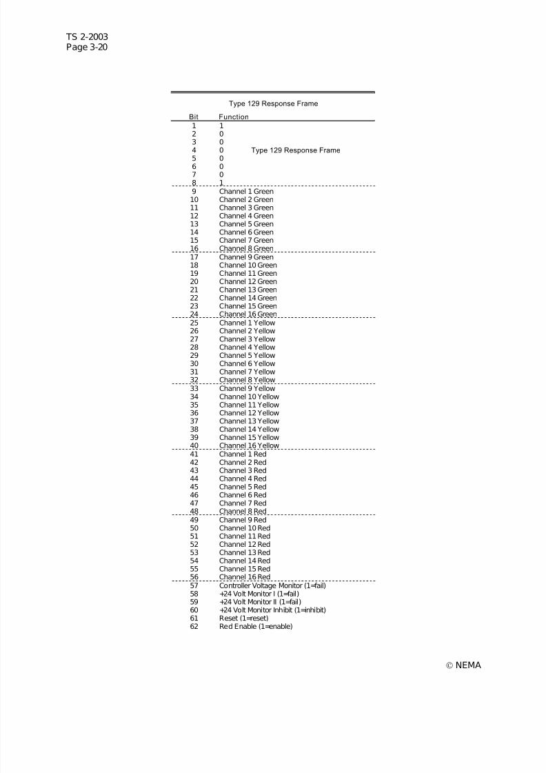
7/30/2019 NEMA TS2-2003- Traffic Controller Assemb
http://slidepdf.com/reader/full/nema-ts2-2003-traffic-controller-assemb 84/246
TS 2-2003Page 3-20
© NEMA
Type 129 Response Frame
Bit Function
1 1
2 03 04 0 Type 129 Response Frame 5 06 07 08 19 Channel 1 Green10 Channel 2 Green11 Channel 3 Green12 Channel 4 Green13 Channel 5 Green14 Channel 6 Green15 Channel 7 Green16 Channel 8 Green17 Channel 9 Green18 Channel 10 Green19 Channel 11 Green20 Channel 12 Green21 Channel 13 Green22 Channel 14 Green23 Channel 15 Green24 Channel 16 Green25 Channel 1 Yellow26 Channel 2 Yellow27 Channel 3 Yellow28 Channel 4 Yellow29 Channel 5 Yellow30 Channel 6 Yellow31 Channel 7 Yellow32 Channel 8 Yellow33 Channel 9 Yellow34 Channel 10 Yellow
35 Channel 11 Yellow36 Channel 12 Yellow37 Channel 13 Yellow38 Channel 14 Yellow39 Channel 15 Yellow40 Channel 16 Yellow41 Channel 1 Red42 Channel 2 Red43 Channel 3 Red44 Channel 4 Red45 Channel 5 Red46 Channel 6 Red47 Channel 7 Red48 Channel 8 Red49 Channel 9 Red50 Channel 10 Red51 Channel 11 Red52 Channel 12 Red53 Channel 13 Red54 Channel 14 Red55 Channel 15 Red56 Channel 16 Red57 Controller Voltage Monitor (1=fail)58 +24 Volt Monitor I (1=fail)59 +24 Volt Monitor II (1=fail)60 +24 Volt Monitor Inhibit (1=inhibit)61 Reset (1=reset)62 Red Enable (1=enable)
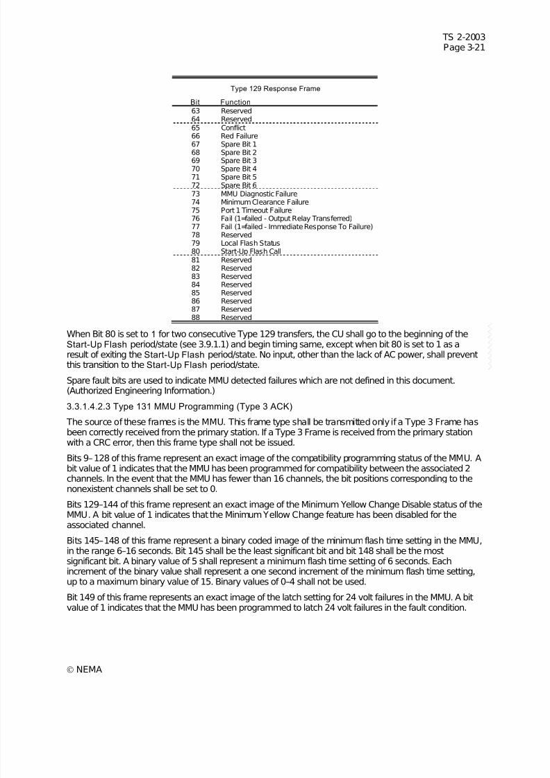
7/30/2019 NEMA TS2-2003- Traffic Controller Assemb
http://slidepdf.com/reader/full/nema-ts2-2003-traffic-controller-assemb 85/246
TS 2-2003Page 3-21
© NEMA
Type 129 Response Frame
Bit Function
63 Reserved64 Reserved65 Conflict
66 Red Failure67 Spare Bit 168 Spare Bit 269 Spare Bit 370 Spare Bit 471 Spare Bit 572 Spare Bit 673 MMU Diagnostic Failure74 Minimum Clearance Failure75 Port 1 Timeout Failure76 Fail (1=failed - Output Relay Transferred)77 Fail (1=failed - Immediate Response To Failure)78 Reserved79 Local Flash Status80 Start-Up Flash Call81 Reserved82 Reserved83 Reserved84 Reserved85 Reserved86 Reserved87 Reserved88 Reserved
When Bit 80 is set to 1 for two consecutive Type 129 transfers, the CU shall go to the beginning of theStart-Up Flash period/state (see 3.9.1.1) and begin timing same, except when bit 80 is set to 1 as aresult of exiting the Start-Up Flash period/state. No input, other than the lack of AC power, shall preventthis transition to the Start-Up Flash period/state.
Spare fault bits are used to indicate MMU detected failures which are not defined in this document.(Authorized Engineering Information.)
3.3.1.4.2.3 Type 131 MMU Programming (Type 3 ACK) The source of these frames is the MMU. This frame type shall be transmitted only if a Type 3 Frame hasbeen correctly received from the primary station. If a Type 3 Frame is received from the primary stationwith a CRC error, then this frame type shall not be issued.
Bits 9–128 of this frame represent an exact image of the compatibility programming status of the MMU. Abit value of 1 indicates that the MMU has been programmed for compatibility between the associated 2channels. In the event that the MMU has fewer than 16 channels, the bit positions corresponding to thenonexistent channels shall be set to 0.
Bits 129–144 of this frame represent an exact image of the Minimum Yellow Change Disable status of theMMU. A bit value of 1 indicates that the Minimum Yellow Change feature has been disabled for theassociated channel.
Bits 145–148 of this frame represent a binary coded image of the minimum flash time setting in the MMU,in the range 6–16 seconds. Bit 145 shall be the least significant bit and bit 148 shall be the mostsignificant bit. A binary value of 5 shall represent a minimum flash time setting of 6 seconds. Eachincrement of the binary value shall represent a one second increment of the minimum flash time setting,up to a maximum binary value of 15. Binary values of 0–4 shall not be used.
Bit 149 of this frame represents an exact image of the latch setting for 24 volt failures in the MMU. A bitvalue of 1 indicates that the MMU has been programmed to latch 24 volt failures in the fault condition.
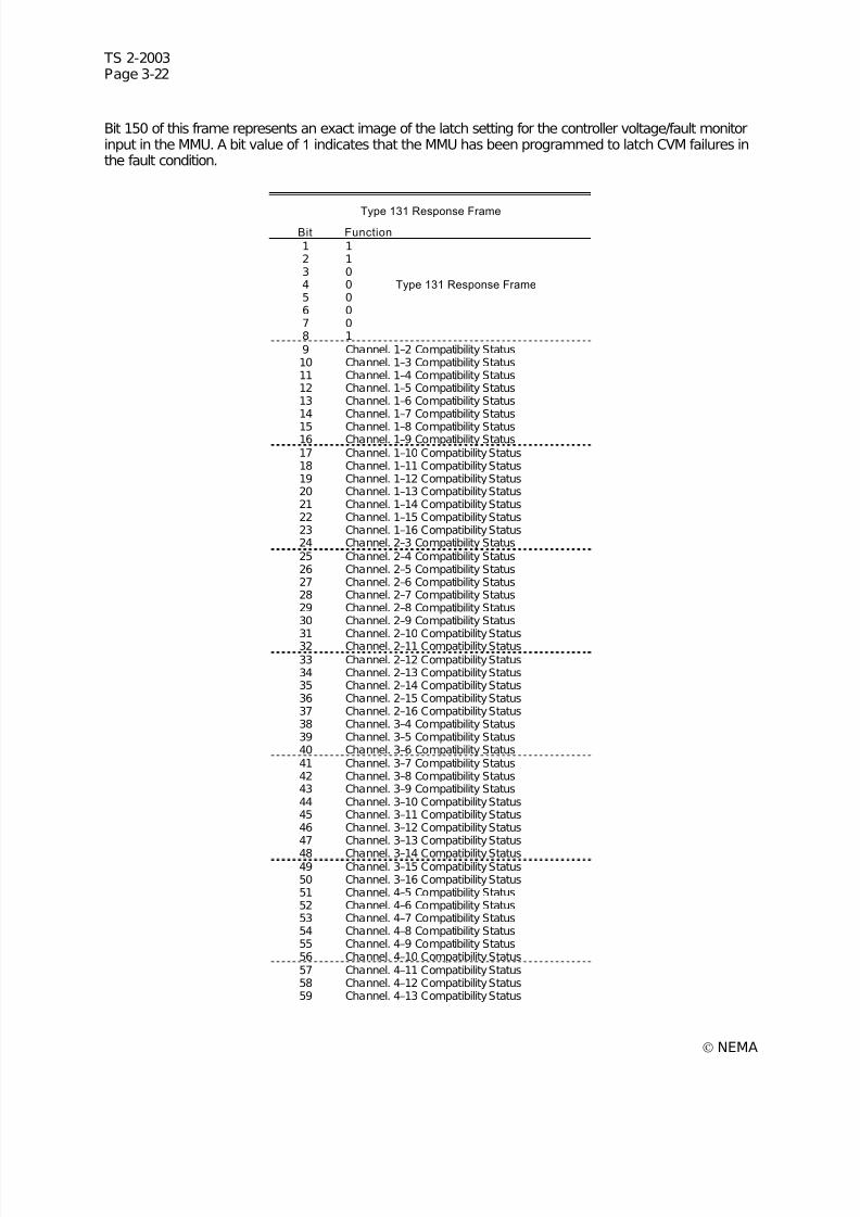
7/30/2019 NEMA TS2-2003- Traffic Controller Assemb
http://slidepdf.com/reader/full/nema-ts2-2003-traffic-controller-assemb 86/246
TS 2-2003Page 3-22
© NEMA
Bit 150 of this frame represents an exact image of the latch setting for the controller voltage/fault monitorinput in the MMU. A bit value of 1 indicates that the MMU has been programmed to latch CVM failures inthe fault condition.
Type 131 Response Frame Bit Function
1 12 13 04 0 Type 131 Response Frame 5 06 07 08 19 Channel. 1–2 Compatibility Status10 Channel. 1–3 Compatibility Status11 Channel. 1–4 Compatibility Status12 Channel. 1–5 Compatibility Status13 Channel. 1–6 Compatibility Status14 Channel. 1–7 Compatibility Status
15 Channel. 1–8 Compatibility Status16 Channel. 1–9 Compatibility Status17 Channel. 1–10 Compatibility Status18 Channel. 1–11 Compatibility Status19 Channel. 1–12 Compatibility Status20 Channel. 1–13 Compatibility Status21 Channel. 1–14 Compatibility Status22 Channel. 1–15 Compatibility Status23 Channel. 1–16 Compatibility Status24 Channel. 2–3 Compatibility Status25 Channel. 2–4 Compatibility Status26 Channel. 2–5 Compatibility Status27 Channel. 2–6 Compatibility Status28 Channel. 2–7 Compatibility Status29 Channel. 2–8 Compatibility Status30 Channel. 2–9 Compatibility Status
31 Channel. 2–10 Compatibility Status32 Channel. 2–11 Compatibility Status33 Channel. 2–12 Compatibility Status34 Channel. 2–13 Compatibility Status35 Channel. 2–14 Compatibility Status36 Channel. 2–15 Compatibility Status37 Channel. 2–16 Compatibility Status38 Channel. 3–4 Compatibility Status39 Channel. 3–5 Compatibility Status40 Channel. 3–6 Compatibility Status41 Channel. 3–7 Compatibility Status42 Channel. 3–8 Compatibility Status43 Channel. 3–9 Compatibility Status44 Channel. 3–10 Compatibility Status45 Channel. 3–11 Compatibility Status46 Channel. 3–12 Compatibility Status47 Channel. 3–13 Compatibility Status
48 Channel. 3–14 Compatibility Status49 Channel. 3–15 Compatibility Status50 Channel. 3–16 Compatibility Status51 Channel. 4–5 Compatibility Status52 Channel. 4–6 Compatibility Status53 Channel. 4–7 Compatibility Status54 Channel. 4–8 Compatibility Status55 Channel. 4–9 Compatibility Status56 Channel. 4–10 Compatibility Status57 Channel. 4–11 Compatibility Status58 Channel. 4–12 Compatibility Status59 Channel. 4–13 Compatibility Status
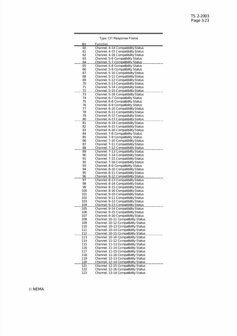
7/30/2019 NEMA TS2-2003- Traffic Controller Assemb
http://slidepdf.com/reader/full/nema-ts2-2003-traffic-controller-assemb 87/246
TS 2-2003Page 3-23
© NEMA
Type 131 Response Frame
Bit Function
60 Channel. 4–14 Compatibility Status61 Channel. 4–15 Compatibility Status62 Channel. 4–16 Compatibility Status
63 Channel. 5–6 Compatibility Status64 Channel. 5–7 Compatibility Status65 Channel. 5–8 Compatibility Status66 Channel. 5–9 Compatibility Status67 Channel. 5–10 Compatibility Status68 Channel. 5–11 Compatibility Status69 Channel. 5–12 Compatibility Status70 Channel. 5–13 Compatibility Status71 Channel. 5–14 Compatibility Status72 Channel. 5–15 Compatibility Status73 Channel. 5–16 Compatibility Status74 Channel. 6–7 Compatibility Status75 Channel. 6–8 Compatibility Status76 Channel. 6–9 Compatibility Status77 Channel. 6–10 Compatibility Status78 Channel. 6–11 Compatibility Status79 Channel. 6–12 Compatibility Status80 Channel. 6–13 Compatibility Status81 Channel. 6–14 Compatibility Status82 Channel. 6–15 Compatibility Status83 Channel. 6–16 Compatibility Status84 Channel. 7–8 Compatibility Status85 Channel. 7–9 Compatibility Status86 Channel. 7–10 Compatibility Status87 Channel. 7–11 Compatibility Status88 Channel. 7–12 Compatibility Status89 Channel. 7–13 Compatibility Status90 Channel. 7–14 Compatibility Status91 Channel. 7–15 Compatibility Status92 Channel. 7–16 Compatibility Status93 Channel. 8–9 Compatibility Status94 Channel. 8–10 Compatibility Status95 Channel. 8–11 Compatibility Status
96 Channel. 8–12 Compatibility Status97 Channel. 8–13 Compatibility Status98 Channel. 8–14 Compatibility Status99 Channel. 8–15 Compatibility Status100 Channel. 8–16 Compatibility Status101 Channel. 9–10 Compatibility Status102 Channel. 9–11 Compatibility Status103 Channel. 9–12 Compatibility Status104 Channel. 9–13 Compatibility Status105 Channel. 9–14 Compatibility Status106 Channel. 9–15 Compatibility Status107 Channel. 9–16 Compatibility Status108 Channel. 10–11 Compatibility Status109 Channel. 10–12 Compatibility Status110 Channel. 10–13 Compatibility Status111 Channel. 10–14 Compatibility Status112 Channel. 10–15 Compatibility Status113 Channel. 10–16 Compatibility Status114 Channel. 11–12 Compatibility Status115 Channel. 11–13 Compatibility Status116 Channel. 11–14 Compatibility Status117 Channel. 11–15 Compatibility Status118 Channel. 11–16 Compatibility Status119 Channel. 12–13 Compatibility Status120 Channel. 12–14 Compatibility Status121 Channel. 12–15 Compatibility Status122 Channel. 12–16 Compatibility Status123 Channel. 13–14 Compatibility Status
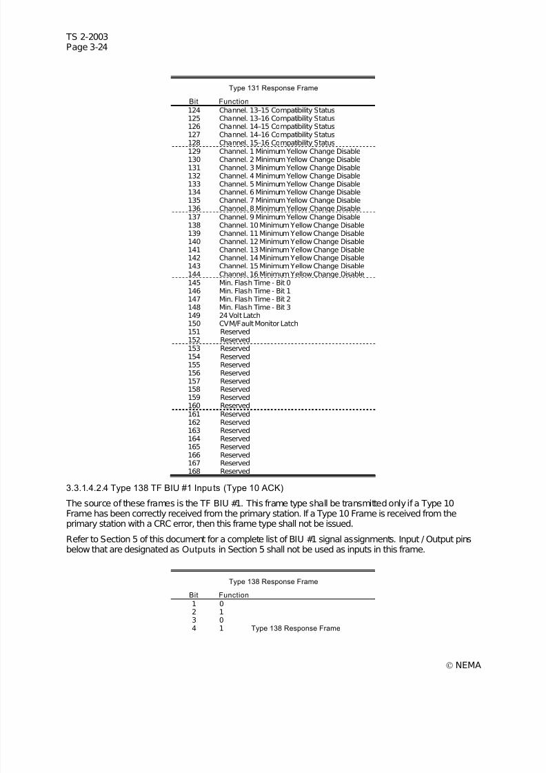
7/30/2019 NEMA TS2-2003- Traffic Controller Assemb
http://slidepdf.com/reader/full/nema-ts2-2003-traffic-controller-assemb 88/246
TS 2-2003Page 3-24
© NEMA
Type 131 Response Frame
Bit Function
124 Channel. 13–15 Compatibility Status125 Channel. 13–16 Compatibility Status126 Channel. 14–15 Compatibility Status
127 Channel. 14–16 Compatibility Status128 Channel. 15–16 Compatibility Status129 Channel. 1 Minimum Yellow Change Disable130 Channel. 2 Minimum Yellow Change Disable131 Channel. 3 Minimum Yellow Change Disable132 Channel. 4 Minimum Yellow Change Disable133 Channel. 5 Minimum Yellow Change Disable134 Channel. 6 Minimum Yellow Change Disable135 Channel. 7 Minimum Yellow Change Disable136 Channel. 8 Minimum Yellow Change Disable137 Channel. 9 Minimum Yellow Change Disable138 Channel. 10 Minimum Yellow Change Disable139 Channel. 11 Minimum Yellow Change Disable140 Channel. 12 Minimum Yellow Change Disable141 Channel. 13 Minimum Yellow Change Disable142 Channel. 14 Minimum Yellow Change Disable143 Channel. 15 Minimum Yellow Change Disable144 Channel. 16 Minimum Yellow Change Disable145 Min. Flash Time - Bit 0146 Min. Flash Time - Bit 1147 Min. Flash Time - Bit 2148 Min. Flash Time - Bit 3149 24 Volt Latch150 CVM/Fault Monitor Latch151 Reserved152 Reserved153 Reserved154 Reserved155 Reserved156 Reserved157 Reserved158 Reserved159 Reserved
160 Reserved161 Reserved162 Reserved163 Reserved164 Reserved165 Reserved166 Reserved167 Reserved168 Reserved
3.3.1.4.2.4 Type 138 TF BIU #1 Inputs (Type 10 ACK)
The source of these frames is the TF BIU #1. This frame type shall be transmitted only if a Type 10Frame has been correctly received from the primary station. If a Type 10 Frame is received from theprimary station with a CRC error, then this frame type shall not be issued.
Refer to Section 5 of this document for a complete list of BIU #1 signal assignments. Input / Output pinsbelow that are designated as Outputs in Section 5 shall not be used as inputs in this frame.
Type 138 Response Frame
Bit Function
1 02 13 04 1 Type 138 Response Frame
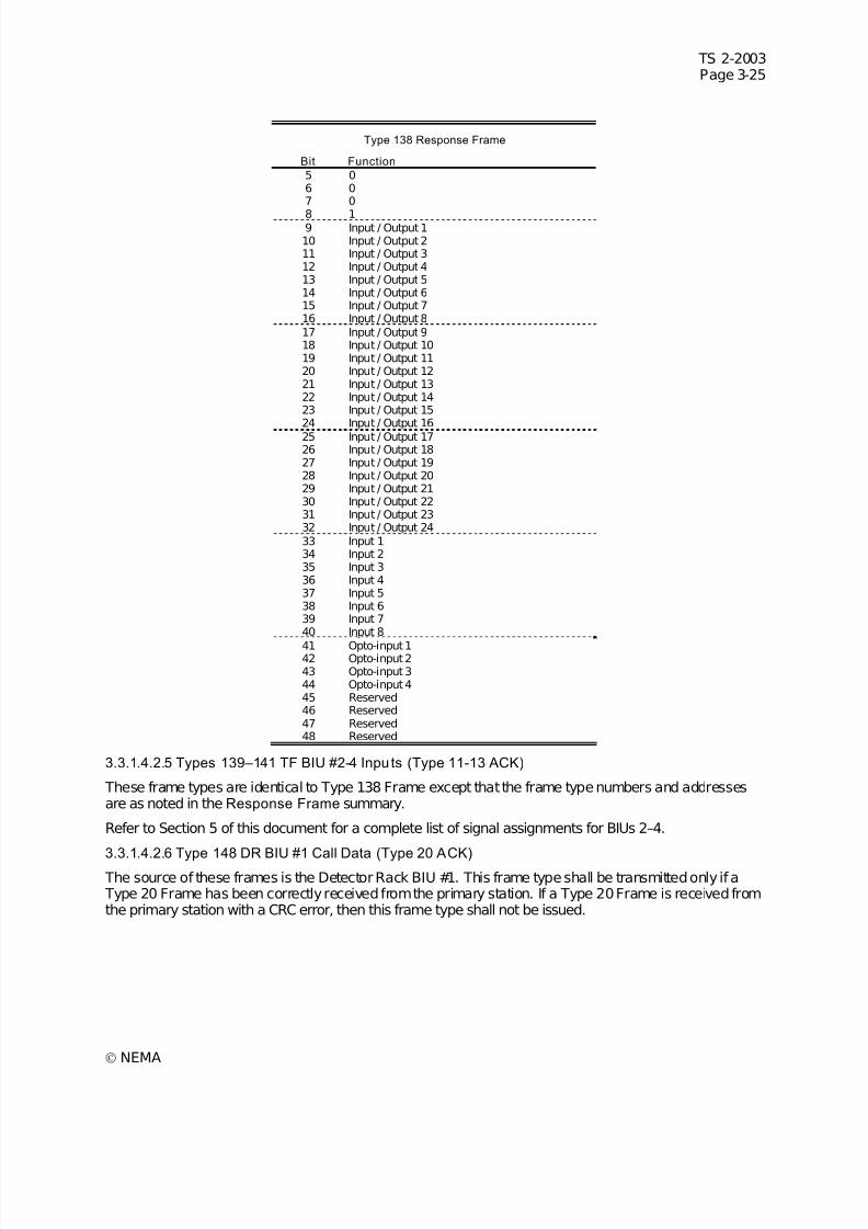
7/30/2019 NEMA TS2-2003- Traffic Controller Assemb
http://slidepdf.com/reader/full/nema-ts2-2003-traffic-controller-assemb 89/246
TS 2-2003Page 3-25
© NEMA
Type 138 Response Frame
Bit Function
5 06 07 0
8 19 Input / Output 110 Input / Output 211 Input / Output 312 Input / Output 413 Input / Output 514 Input / Output 615 Input / Output 716 Input / Output 817 Input / Output 918 Input / Output 1019 Input / Output 1120 Input / Output 1221 Input / Output 1322 Input / Output 1423 Input / Output 1524 Input / Output 1625 Input / Output 1726 Input / Output 1827 Input / Output 1928 Input / Output 2029 Input / Output 2130 Input / Output 2231 Input / Output 2332 Input / Output 2433 Input 134 Input 235 Input 336 Input 437 Input 538 Input 639 Input 740 Input 8
41 Opto-input 142 Opto-input 243 Opto-input 344 Opto-input 445 Reserved46 Reserved47 Reserved48 Reserved
3.3.1.4.2.5 Types 139–141 TF BIU #2-4 Inputs (Type 11-13 ACK)
These frame types are identical to Type 138 Frame except that the frame type numbers and addressesare as noted in the Response Frame summary.
Refer to Section 5 of this document for a complete list of signal assignments for BIUs 2–4.
3.3.1.4.2.6 Type 148 DR BIU #1 Call Data (Type 20 ACK)
The source of these frames is the Detector Rack BIU #1. This frame type shall be transmitted only if a Type 20 Frame has been correctly received from the primary station. If a Type 20 Frame is received fromthe primary station with a CRC error, then this frame type shall not be issued.
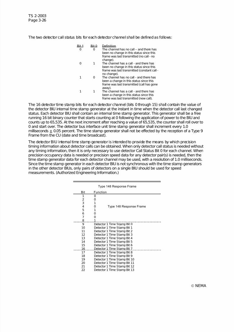
7/30/2019 NEMA TS2-2003- Traffic Controller Assemb
http://slidepdf.com/reader/full/nema-ts2-2003-traffic-controller-assemb 90/246
TS 2-2003Page 3-26
© NEMA
The two detector call status bits for each detector channel shall be defined as follows:
Bit 1 Bit 0 Definition0 0 The channel has no call – and there has
been no change in this status since thisframe was last transmitted (no call - nochange).
0 1 The channel has a call - and there hasbeen no change in this status since thisframe was last transmitted (constant call -no change).
1 0 The channel has no call - and there hasbeen a change in this status since thisframe was last transmitted (call has goneaway).
1 1 The channel has a call - and there hasbeen a change in this status since thisframe was last transmitted (new call).
The 16 detector time stamp bits for each detector channel (bits 0 through 15) shall contain the value of the detector BIU internal time stamp generator at the instant in time when the detector call last changedstatus. Each detector BIU shall contain an internal time stamp generator. This generator shall be a freerunning 16 bit binary counter that starts counting at 0 following the application of power to the BIU andcounts up to 65,535. At the next increment after reaching a value of 65,535, the counter shall roll over to0 and start over. The detector bus interface unit time stamp generator shall increment every 1.0milliseconds + 0.05 percent. The time stamp generator shall not be effected by the reception of a Type 9Frame from the CU (date and time broadcast).
The detector BIU internal time stamp generator is intended to provide the means by which precisiontiming information about detector calls can be obtained. When only detector call status is needed withoutany timing information, then it is only necessary to use detector Call Status Bit 0 for each channel. Whenprecision occupancy data is needed or precision speed data for any detector pair(s) is needed, then thetime stamp generator data for each detector channel may be used, with a resolution of 1.0 milliseconds.Since the time stamp generator in each detector BIU is not synchronous with the time stamp generatorsin the other detector BIUs, only pairs of detectors on a single BIU should be used for speed
measurements. (Authorized Engineering Information.)
Type 148 Response Frame
Bit Function
1 02 03 14 0 Type 148 Response Frame 5 16 07 08 19 Detector 1 Time Stamp Bit 010 Detector 1 Time Stamp Bit 1
11 Detector 1 Time Stamp Bit 212 Detector 1 Time Stamp Bit 313 Detector 1 Time Stamp Bit 414 Detector 1 Time Stamp Bit 515 Detector 1 Time Stamp Bit 616 Detector 1 Time Stamp Bit 717 Detector 1 Time Stamp Bit 818 Detector 1 Time Stamp Bit 919 Detector 1 Time Stamp Bit 1020 Detector 1 Time Stamp Bit 1121 Detector 1 Time Stamp Bit 1222 Detector 1 Time Stamp Bit 13
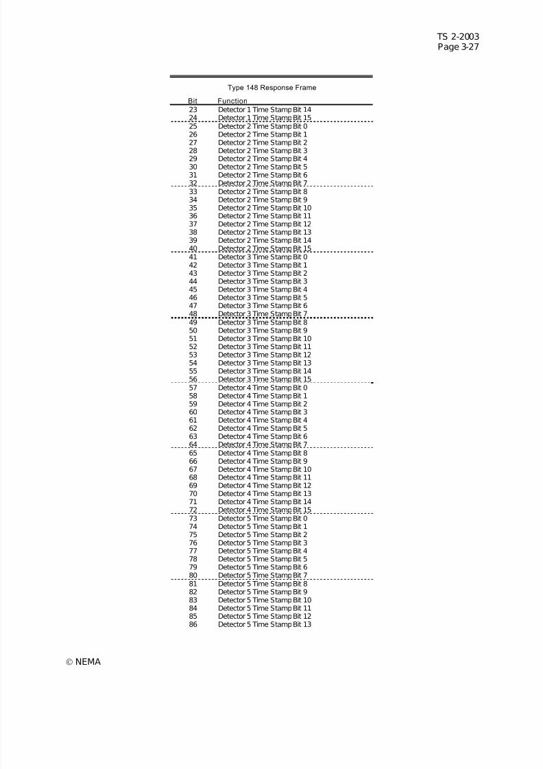
7/30/2019 NEMA TS2-2003- Traffic Controller Assemb
http://slidepdf.com/reader/full/nema-ts2-2003-traffic-controller-assemb 91/246
TS 2-2003Page 3-27
© NEMA
Type 148 Response Frame
Bit Function
23 Detector 1 Time Stamp Bit 1424 Detector 1 Time Stamp Bit 1525 Detector 2 Time Stamp Bit 0
26 Detector 2 Time Stamp Bit 127 Detector 2 Time Stamp Bit 228 Detector 2 Time Stamp Bit 329 Detector 2 Time Stamp Bit 430 Detector 2 Time Stamp Bit 531 Detector 2 Time Stamp Bit 632 Detector 2 Time Stamp Bit 733 Detector 2 Time Stamp Bit 834 Detector 2 Time Stamp Bit 935 Detector 2 Time Stamp Bit 1036 Detector 2 Time Stamp Bit 1137 Detector 2 Time Stamp Bit 1238 Detector 2 Time Stamp Bit 1339 Detector 2 Time Stamp Bit 1440 Detector 2 Time Stamp Bit 1541 Detector 3 Time Stamp Bit 042 Detector 3 Time Stamp Bit 143 Detector 3 Time Stamp Bit 244 Detector 3 Time Stamp Bit 345 Detector 3 Time Stamp Bit 446 Detector 3 Time Stamp Bit 547 Detector 3 Time Stamp Bit 648 Detector 3 Time Stamp Bit 749 Detector 3 Time Stamp Bit 850 Detector 3 Time Stamp Bit 951 Detector 3 Time Stamp Bit 1052 Detector 3 Time Stamp Bit 1153 Detector 3 Time Stamp Bit 1254 Detector 3 Time Stamp Bit 1355 Detector 3 Time Stamp Bit 1456 Detector 3 Time Stamp Bit 1557 Detector 4 Time Stamp Bit 058 Detector 4 Time Stamp Bit 1
59 Detector 4 Time Stamp Bit 260 Detector 4 Time Stamp Bit 361 Detector 4 Time Stamp Bit 462 Detector 4 Time Stamp Bit 563 Detector 4 Time Stamp Bit 664 Detector 4 Time Stamp Bit 765 Detector 4 Time Stamp Bit 866 Detector 4 Time Stamp Bit 967 Detector 4 Time Stamp Bit 1068 Detector 4 Time Stamp Bit 1169 Detector 4 Time Stamp Bit 1270 Detector 4 Time Stamp Bit 1371 Detector 4 Time Stamp Bit 1472 Detector 4 Time Stamp Bit 1573 Detector 5 Time Stamp Bit 074 Detector 5 Time Stamp Bit 175 Detector 5 Time Stamp Bit 276 Detector 5 Time Stamp Bit 377 Detector 5 Time Stamp Bit 478 Detector 5 Time Stamp Bit 579 Detector 5 Time Stamp Bit 680 Detector 5 Time Stamp Bit 781 Detector 5 Time Stamp Bit 882 Detector 5 Time Stamp Bit 983 Detector 5 Time Stamp Bit 1084 Detector 5 Time Stamp Bit 1185 Detector 5 Time Stamp Bit 1286 Detector 5 Time Stamp Bit 13
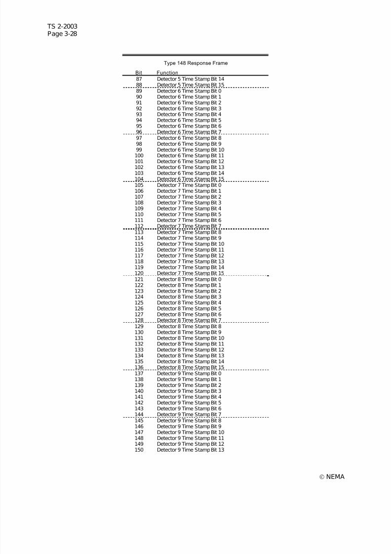
7/30/2019 NEMA TS2-2003- Traffic Controller Assemb
http://slidepdf.com/reader/full/nema-ts2-2003-traffic-controller-assemb 92/246
TS 2-2003Page 3-28
© NEMA
Type 148 Response Frame
Bit Function
87 Detector 5 Time Stamp Bit 1488 Detector 5 Time Stamp Bit 1589 Detector 6 Time Stamp Bit 0
90 Detector 6 Time Stamp Bit 191 Detector 6 Time Stamp Bit 292 Detector 6 Time Stamp Bit 393 Detector 6 Time Stamp Bit 494 Detector 6 Time Stamp Bit 595 Detector 6 Time Stamp Bit 696 Detector 6 Time Stamp Bit 797 Detector 6 Time Stamp Bit 898 Detector 6 Time Stamp Bit 999 Detector 6 Time Stamp Bit 10100 Detector 6 Time Stamp Bit 11101 Detector 6 Time Stamp Bit 12102 Detector 6 Time Stamp Bit 13103 Detector 6 Time Stamp Bit 14104 Detector 6 Time Stamp Bit 15105 Detector 7 Time Stamp Bit 0106 Detector 7 Time Stamp Bit 1107 Detector 7 Time Stamp Bit 2108 Detector 7 Time Stamp Bit 3109 Detector 7 Time Stamp Bit 4110 Detector 7 Time Stamp Bit 5111 Detector 7 Time Stamp Bit 6112 Detector 7 Time Stamp Bit 7113 Detector 7 Time Stamp Bit 8114 Detector 7 Time Stamp Bit 9115 Detector 7 Time Stamp Bit 10116 Detector 7 Time Stamp Bit 11117 Detector 7 Time Stamp Bit 12118 Detector 7 Time Stamp Bit 13119 Detector 7 Time Stamp Bit 14120 Detector 7 Time Stamp Bit 15121 Detector 8 Time Stamp Bit 0122 Detector 8 Time Stamp Bit 1
123 Detector 8 Time Stamp Bit 2124 Detector 8 Time Stamp Bit 3125 Detector 8 Time Stamp Bit 4126 Detector 8 Time Stamp Bit 5127 Detector 8 Time Stamp Bit 6128 Detector 8 Time Stamp Bit 7129 Detector 8 Time Stamp Bit 8130 Detector 8 Time Stamp Bit 9131 Detector 8 Time Stamp Bit 10132 Detector 8 Time Stamp Bit 11133 Detector 8 Time Stamp Bit 12134 Detector 8 Time Stamp Bit 13135 Detector 8 Time Stamp Bit 14136 Detector 8 Time Stamp Bit 15137 Detector 9 Time Stamp Bit 0138 Detector 9 Time Stamp Bit 1139 Detector 9 Time Stamp Bit 2140 Detector 9 Time Stamp Bit 3141 Detector 9 Time Stamp Bit 4142 Detector 9 Time Stamp Bit 5143 Detector 9 Time Stamp Bit 6144 Detector 9 Time Stamp Bit 7145 Detector 9 Time Stamp Bit 8146 Detector 9 Time Stamp Bit 9147 Detector 9 Time Stamp Bit 10148 Detector 9 Time Stamp Bit 11149 Detector 9 Time Stamp Bit 12150 Detector 9 Time Stamp Bit 13

7/30/2019 NEMA TS2-2003- Traffic Controller Assemb
http://slidepdf.com/reader/full/nema-ts2-2003-traffic-controller-assemb 93/246
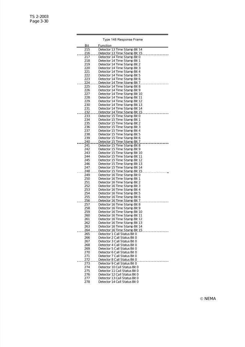
7/30/2019 NEMA TS2-2003- Traffic Controller Assemb
http://slidepdf.com/reader/full/nema-ts2-2003-traffic-controller-assemb 94/246
TS 2-2003Page 3-30
© NEMA
Type 148 Response Frame
Bit Function
215 Detector 13 Time Stamp Bit 14216 Detector 13 Time Stamp Bit 15217 Detector 14 Time Stamp Bit 0
218 Detector 14 Time Stamp Bit 1219 Detector 14 Time Stamp Bit 2220 Detector 14 Time Stamp Bit 3221 Detector 14 Time Stamp Bit 4222 Detector 14 Time Stamp Bit 5223 Detector 14 Time Stamp Bit 6224 Detector 14 Time Stamp Bit 7225 Detector 14 Time Stamp Bit 8226 Detector 14 Time Stamp Bit 9227 Detector 14 Time Stamp Bit 10228 Detector 14 Time Stamp Bit 11229 Detector 14 Time Stamp Bit 12230 Detector 14 Time Stamp Bit 13231 Detector 14 Time Stamp Bit 14232 Detector 14 Time Stamp Bit 15233 Detector 15 Time Stamp Bit 0234 Detector 15 Time Stamp Bit 1235 Detector 15 Time Stamp Bit 2236 Detector 15 Time Stamp Bit 3237 Detector 15 Time Stamp Bit 4238 Detector 15 Time Stamp Bit 5239 Detector 15 Time Stamp Bit 6240 Detector 15 Time Stamp Bit 7241 Detector 15 Time Stamp Bit 8242 Detector 15 Time Stamp Bit 9243 Detector 15 Time Stamp Bit 10244 Detector 15 Time Stamp Bit 11245 Detector 15 Time Stamp Bit 12246 Detector 15 Time Stamp Bit 13247 Detector 15 Time Stamp Bit 14248 Detector 15 Time Stamp Bit 15249 Detector 16 Time Stamp Bit 0250 Detector 16 Time Stamp Bit 1
251 Detector 16 Time Stamp Bit 2252 Detector 16 Time Stamp Bit 3253 Detector 16 Time Stamp Bit 4254 Detector 16 Time Stamp Bit 5255 Detector 16 Time Stamp Bit 6256 Detector 16 Time Stamp Bit 7257 Detector 16 Time Stamp Bit 8258 Detector 16 Time Stamp Bit 9259 Detector 16 Time Stamp Bit 10260 Detector 16 Time Stamp Bit 11261 Detector 16 Time Stamp Bit 12262 Detector 16 Time Stamp Bit 13263 Detector 16 Time Stamp Bit 14264 Detector 16 Time Stamp Bit 15265 Detector 1 Call Status Bit 0266 Detector 2 Call Status Bit 0267 Detector 3 Call Status Bit 0268 Detector 4 Call Status Bit 0269 Detector 5 Call Status Bit 0270 Detector 6 Call Status Bit 0271 Detector 7 Call Status Bit 0272 Detector 8 Call Status Bit 0273 Detector 9 Call Status Bit 0274 Detector 10 Call Status Bit 0275 Detector 11 Call Status Bit 0276 Detector 12 Call Status Bit 0277 Detector 13 Call Status Bit 0278 Detector 14 Call Status Bit 0
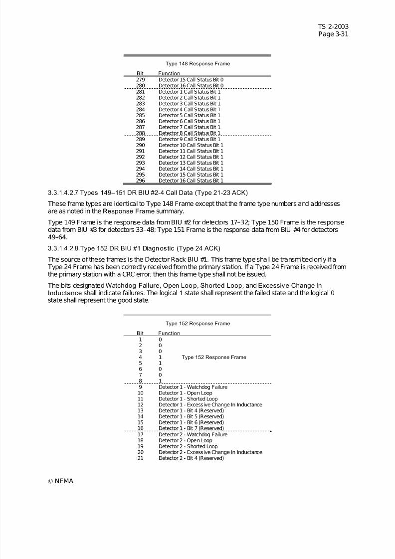
7/30/2019 NEMA TS2-2003- Traffic Controller Assemb
http://slidepdf.com/reader/full/nema-ts2-2003-traffic-controller-assemb 95/246
TS 2-2003Page 3-31
© NEMA
Type 148 Response Frame
Bit Function
279 Detector 15 Call Status Bit 0280 Detector 16 Call Status Bit 0281 Detector 1 Call Status Bit 1
282 Detector 2 Call Status Bit 1283 Detector 3 Call Status Bit 1284 Detector 4 Call Status Bit 1285 Detector 5 Call Status Bit 1286 Detector 6 Call Status Bit 1287 Detector 7 Call Status Bit 1288 Detector 8 Call Status Bit 1289 Detector 9 Call Status Bit 1290 Detector 10 Call Status Bit 1291 Detector 11 Call Status Bit 1292 Detector 12 Call Status Bit 1293 Detector 13 Call Status Bit 1294 Detector 14 Call Status Bit 1295 Detector 15 Call Status Bit 1296 Detector 16 Call Status Bit 1
3.3.1.4.2.7 Types 149–151 DR BIU #2-4 Call Data (Type 21-23 ACK) These frame types are identical to Type 148 Frame except that the frame type numbers and addressesare as noted in the Response Frame summary.
Type 149 Frame is the response data from BIU #2 for detectors 17–32; Type 150 Frame is the responsedata from BIU #3 for detectors 33–48; Type 151 Frame is the response data from BIU #4 for detectors49–64.
3.3.1.4.2.8 Type 152 DR BIU #1 Diagnostic (Type 24 ACK)
The source of these frames is the Detector Rack BIU #1. This frame type shall be transmitted only if a Type 24 Frame has been correctly received from the primary station. If a Type 24 Frame is received fromthe primary station with a CRC error, then this frame type shall not be issued.
The bits designatedWatchdog Failure, Open Loop, Shorted Loop, and Excessive Change In
Inductance shall indicate failures. The logical 1 state shall represent the failed state and the logical 0 state shall represent the good state.
Type 152 Response Frame
Bit Function
1 02 03 04 1 Type 152 Response Frame 5 16 07 08 19 Detector 1 - Watchdog Failure
10 Detector 1 - Open Loop11 Detector 1 - Shorted Loop12 Detector 1 - Excessive Change In Inductance13 Detector 1 - Bit 4 (Reserved)14 Detector 1 - Bit 5 (Reserved)15 Detector 1 - Bit 6 (Reserved)16 Detector 1 - Bit 7 (Reserved)17 Detector 2 - Watchdog Failure18 Detector 2 - Open Loop19 Detector 2 - Shorted Loop20 Detector 2 - Excessive Change In Inductance21 Detector 2 - Bit 4 (Reserved)
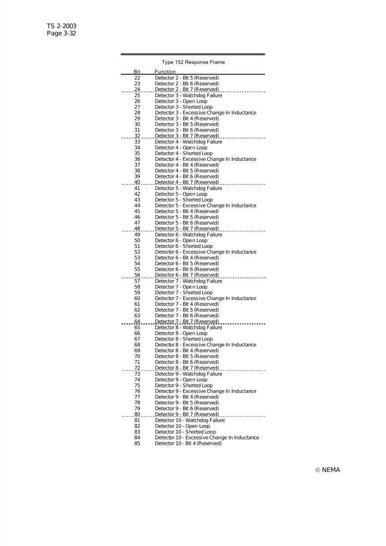
7/30/2019 NEMA TS2-2003- Traffic Controller Assemb
http://slidepdf.com/reader/full/nema-ts2-2003-traffic-controller-assemb 96/246
TS 2-2003Page 3-32
© NEMA
Type 152 Response Frame
Bit Function
22 Detector 2 - Bit 5 (Reserved)23 Detector 2 - Bit 6 (Reserved)24 Detector 2 - Bit 7 (Reserved)
25 Detector 3 - Watchdog Failure26 Detector 3 - Open Loop27 Detector 3 - Shorted Loop28 Detector 3 - Excessive Change In Inductance29 Detector 3 - Bit 4 (Reserved)30 Detector 3 - Bit 5 (Reserved)31 Detector 3 - Bit 6 (Reserved)32 Detector 3 - Bit 7 (Reserved)33 Detector 4 - Watchdog Failure34 Detector 4 - Open Loop35 Detector 4 - Shorted Loop36 Detector 4 - Excessive Change In Inductance37 Detector 4 - Bit 4 (Reserved)38 Detector 4 - Bit 5 (Reserved)39 Detector 4 - Bit 6 (Reserved)40 Detector 4 - Bit 7 (Reserved)41 Detector 5 - Watchdog Failure42 Detector 5 - Open Loop43 Detector 5 - Shorted Loop44 Detector 5 - Excessive Change In Inductance45 Detector 5 - Bit 4 (Reserved)46 Detector 5 - Bit 5 (Reserved)47 Detector 5 - Bit 6 (Reserved)48 Detector 5 - Bit 7 (Reserved)49 Detector 6 - Watchdog Failure50 Detector 6 - Open Loop51 Detector 6 - Shorted Loop52 Detector 6 - Excessive Change In Inductance53 Detector 6 - Bit 4 (Reserved)54 Detector 6 - Bit 5 (Reserved)55 Detector 6 - Bit 6 (Reserved)56 Detector 6 - Bit 7 (Reserved)57 Detector 7 - Watchdog Failure
58 Detector 7 - Open Loop59 Detector 7 - Shorted Loop60 Detector 7 - Excessive Change In Inductance61 Detector 7 - Bit 4 (Reserved)62 Detector 7 - Bit 5 (Reserved)63 Detector 7 - Bit 6 (Reserved)64 Detector 7 - Bit 7 (Reserved)65 Detector 8 - Watchdog Failure66 Detector 8 - Open Loop67 Detector 8 - Shorted Loop68 Detector 8 - Excessive Change In Inductance69 Detector 8 - Bit 4 (Reserved)70 Detector 8 - Bit 5 (Reserved)71 Detector 8 - Bit 6 (Reserved)72 Detector 8 - Bit 7 (Reserved)73 Detector 9 - Watchdog Failure74 Detector 9 - Open Loop75 Detector 9 - Shorted Loop76 Detector 9 - Excessive Change In Inductance77 Detector 9 - Bit 4 (Reserved)78 Detector 9 - Bit 5 (Reserved)79 Detector 9 - Bit 6 (Reserved)80 Detector 9 - Bit 7 (Reserved)81 Detector 10 - Watchdog Failure82 Detector 10 - Open Loop83 Detector 10 - Shorted Loop84 Detector 10 - Excessive Change In Inductance85 Detector 10 - Bit 4 (Reserved)
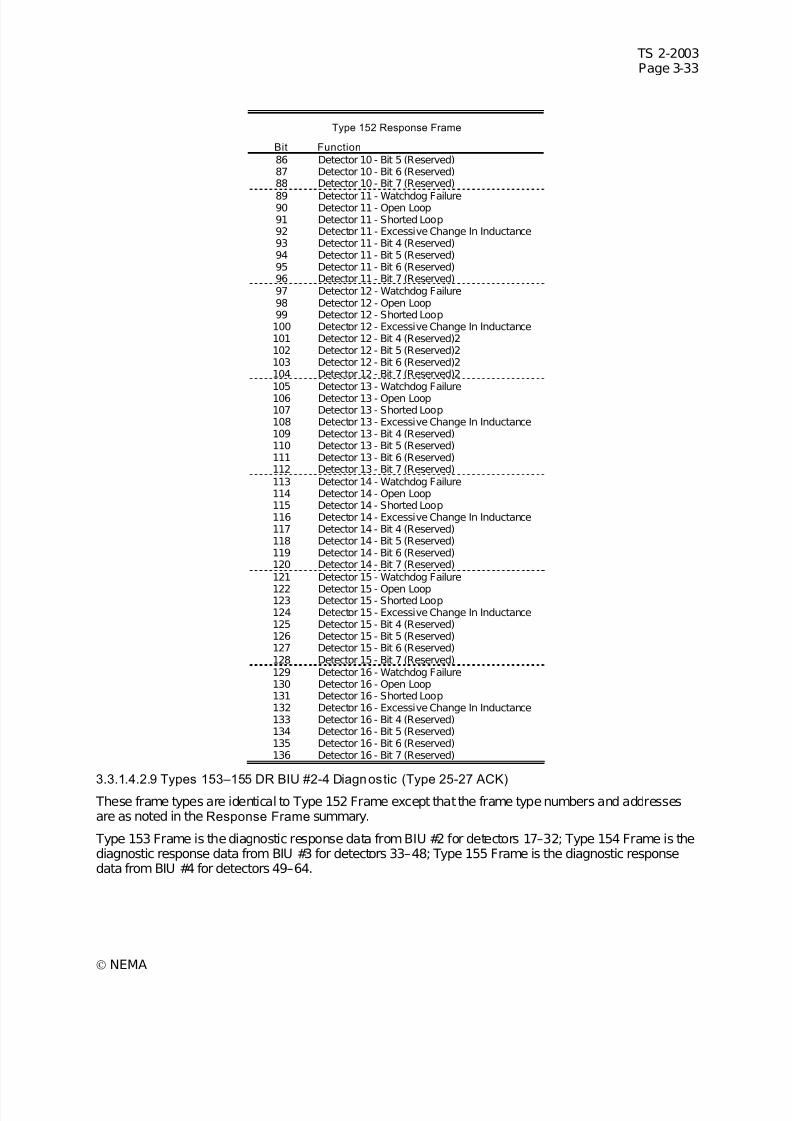
7/30/2019 NEMA TS2-2003- Traffic Controller Assemb
http://slidepdf.com/reader/full/nema-ts2-2003-traffic-controller-assemb 97/246
TS 2-2003Page 3-33
© NEMA
Type 152 Response Frame
Bit Function
86 Detector 10 - Bit 5 (Reserved)87 Detector 10 - Bit 6 (Reserved)88 Detector 10 - Bit 7 (Reserved)
89 Detector 11 - Watchdog Failure90 Detector 11 - Open Loop91 Detector 11 - Shorted Loop92 Detector 11 - Excessive Change In Inductance93 Detector 11 - Bit 4 (Reserved)94 Detector 11 - Bit 5 (Reserved)95 Detector 11 - Bit 6 (Reserved)96 Detector 11 - Bit 7 (Reserved)97 Detector 12 - Watchdog Failure98 Detector 12 - Open Loop99 Detector 12 - Shorted Loop100 Detector 12 - Excessive Change In Inductance101 Detector 12 - Bit 4 (Reserved)2102 Detector 12 - Bit 5 (Reserved)2103 Detector 12 - Bit 6 (Reserved)2104 Detector 12 - Bit 7 (Reserved)2105 Detector 13 - Watchdog Failure106 Detector 13 - Open Loop107 Detector 13 - Shorted Loop108 Detector 13 - Excessive Change In Inductance109 Detector 13 - Bit 4 (Reserved)110 Detector 13 - Bit 5 (Reserved)111 Detector 13 - Bit 6 (Reserved)112 Detector 13 - Bit 7 (Reserved)113 Detector 14 - Watchdog Failure114 Detector 14 - Open Loop115 Detector 14 - Shorted Loop116 Detector 14 - Excessive Change In Inductance117 Detector 14 - Bit 4 (Reserved)118 Detector 14 - Bit 5 (Reserved)119 Detector 14 - Bit 6 (Reserved)120 Detector 14 - Bit 7 (Reserved)121 Detector 15 - Watchdog Failure
122 Detector 15 - Open Loop123 Detector 15 - Shorted Loop124 Detector 15 - Excessive Change In Inductance125 Detector 15 - Bit 4 (Reserved)126 Detector 15 - Bit 5 (Reserved)127 Detector 15 - Bit 6 (Reserved)128 Detector 15 - Bit 7 (Reserved)129 Detector 16 - Watchdog Failure130 Detector 16 - Open Loop131 Detector 16 - Shorted Loop132 Detector 16 - Excessive Change In Inductance133 Detector 16 - Bit 4 (Reserved)134 Detector 16 - Bit 5 (Reserved)135 Detector 16 - Bit 6 (Reserved)136 Detector 16 - Bit 7 (Reserved)
3.3.1.4.2.9 Types 153–155 DR BIU #2-4 Diagnostic (Type 25-27 ACK) These frame types are identical to Type 152 Frame except that the frame type numbers and addressesare as noted in the Response Frame summary.
Type 153 Frame is the diagnostic response data from BIU #2 for detectors 17–32; Type 154 Frame is thediagnostic response data from BIU #3 for detectors 33–48; Type 155 Frame is the diagnostic responsedata from BIU #4 for detectors 49–64.
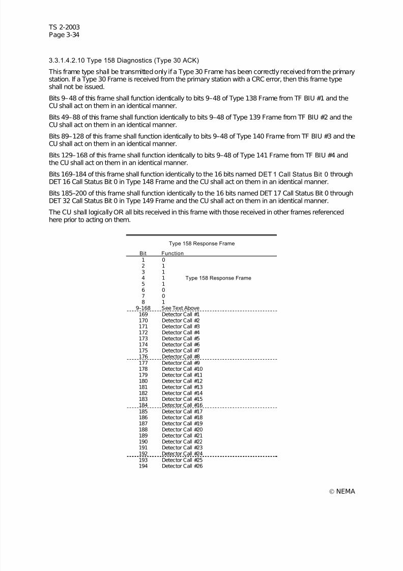
7/30/2019 NEMA TS2-2003- Traffic Controller Assemb
http://slidepdf.com/reader/full/nema-ts2-2003-traffic-controller-assemb 98/246
TS 2-2003Page 3-34
© NEMA
3.3.1.4.2.10 Type 158 Diagnostics (Type 30 ACK)
This frame type shall be transmitted only if a Type 30 Frame has been correctly received from the primarystation. If a Type 30 Frame is received from the primary station with a CRC error, then this frame typeshall not be issued.
Bits 9–48 of this frame shall function identically to bits 9–48 of Type 138 Frame from TF BIU #1 and theCU shall act on them in an identical manner.
Bits 49–88 of this frame shall function identically to bits 9–48 of Type 139 Frame from TF BIU #2 and theCU shall act on them in an identical manner.
Bits 89–128 of this frame shall function identically to bits 9–48 of Type 140 Frame from TF BIU #3 and theCU shall act on them in an identical manner.
Bits 129–168 of this frame shall function identically to bits 9–48 of Type 141 Frame from TF BIU #4 andthe CU shall act on them in an identical manner.
Bits 169–184 of this frame shall function identically to the 16 bits named DET 1 Call Status Bit 0 throughDET 16 Call Status Bit 0 in Type 148 Frame and the CU shall act on them in an identical manner.
Bits 185–200 of this frame shall function identically to the 16 bits named DET 17 Call Status Bit 0 through
DET 32 Call Status Bit 0 in Type 149 Frame and the CU shall act on them in an identical manner.
The CU shall logicallyOR all bits received in this frame with those received in other frames referencedhere prior to acting on them.
Type 158 Response Frame
Bit Function
1 02 13 14 1 Type 158 Response Frame 5 16 07 08 1
9–168 See Text Above169 Detector Call #1170 Detector Call #2171 Detector Call #3172 Detector Call #4173 Detector Call #5174 Detector Call #6175 Detector Call #7176 Detector Call #8177 Detector Call #9178 Detector Call #10179 Detector Call #11180 Detector Call #12181 Detector Call #13182 Detector Call #14
183 Detector Call #15184 Detector Call #16185 Detector Call #17186 Detector Call #18187 Detector Call #19188 Detector Call #20189 Detector Call #21190 Detector Call #22191 Detector Call #23192 Detector Call #24193 Detector Call #25194 Detector Call #26
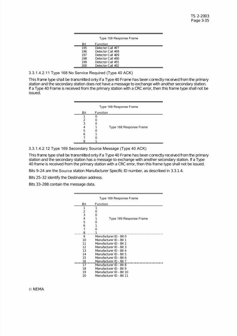
7/30/2019 NEMA TS2-2003- Traffic Controller Assemb
http://slidepdf.com/reader/full/nema-ts2-2003-traffic-controller-assemb 99/246
TS 2-2003Page 3-35
© NEMA
Type 158 Response Frame
Bit Function
195 Detector Call #27196 Detector Call #28197 Detector Call #29
198 Detector Call #30199 Detector Call #31200 Detector Call #32
3.3.1.4.2.11 Type 168 No Service Required (Type 40 ACK)
This frame type shall be transmitted only if a Type 40 Frame has been correctly received from the primarystation and the secondary station does not have a message to exchange with another secondary station.If a Type 40 Frame is received from the primary station with a CRC error, then this frame type shall not beissued.
Type 168 Response Frame
Bit Function
1 02 03 04 1 Type 168 Response Frame 5 06 17 08 1
3.3.1.4.2.12 Type 169 Secondary Source Message (Type 40 ACK)
This frame type shall be transmitted only if a Type 40 Frame has been correctly received from the primarystation and the secondary station has a message to exchange with another secondary station. If a Type40 frame is received from the primary station with a CRC error, then this frame type shall not be issued.
Bits 9–24 are the Source station Manufacturer Specific ID number, as described in 3.3.1.4.
Bits 25–32 identify the Destination address.
Bits 33–288 contain the message data.
Type 169 Response Frame
Bit Function
1 12 03 04 1 Type 169 Response Frame 5 06 17 08 1
9 Manufacturer ID - Bit 010 Manufacturer ID - Bit 111 Manufacturer ID - Bit 212 Manufacturer ID - Bit 313 Manufacturer ID - Bit 414 Manufacturer ID - Bit 515 Manufacturer ID - Bit 616 Manufacturer ID - Bit 717 Manufacturer ID - Bit 818 Manufacturer ID - Bit 919 Manufacturer ID - Bit 1020 Manufacturer ID - Bit 11
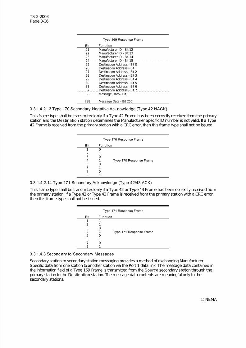
7/30/2019 NEMA TS2-2003- Traffic Controller Assemb
http://slidepdf.com/reader/full/nema-ts2-2003-traffic-controller-assemb 100/246
TS 2-2003Page 3-36
© NEMA
Type 169 Response Frame
Bit Function
21 Manufacturer ID - Bit 1222 Manufacturer ID - Bit 1323 Manufacturer ID - Bit 14
24 Manufacturer ID - Bit 1525 Destination Address - Bit 026 Destination Address - Bit 127 Destination Address - Bit 228 Destination Address - Bit 329 Destination Address - Bit 430 Destination Address - Bit 531 Destination Address - Bit 632 Destination Address - Bit 733 Message Data - Bit 1
|288 Message Data - Bit 256
3.3.1.4.2.13 Type 170 Secondary Negative Acknowledge (Type 42 NACK)
This frame type shall be transmitted only if a Type 42 Frame has been correctly received from the primary
station and the Destination station determines the Manufacturer Specific ID number is not valid. If a Type42 Frame is received from the primary station with a CRC error, then this frame type shall not be issued.
Type 170 Response Frame
Bit Function
1 02 13 04 1 Type 170 Response Frame 5 06 17 08 1
3.3.1.4.2.14 Type 171 Secondary Acknowledge (Type 42/43 ACK)
This frame type shall be transmitted only if a Type 42 or Type 43 Frame has been correctly received fromthe primary station. If a Type 42 or Type 43 Frame is received from the primary station with a CRC error,then this frame type shall not be issued.
Type 171 Response Frame
Bit Function
1 12 13 04 1 Type 171 Response Frame 5 06 1
7 08 1
3.3.1.4.3 Secondary to Secondary Messages
Secondary station to secondary station messaging provides a method of exchanging ManufacturerSpecific data from one station to another station via the Port 1 data link. The message data contained inthe information field of a Type 169 Frame is transmitted from the Source secondary station through theprimary station to the Destination station. The message data contents are meaningful only to thesecondary stations.
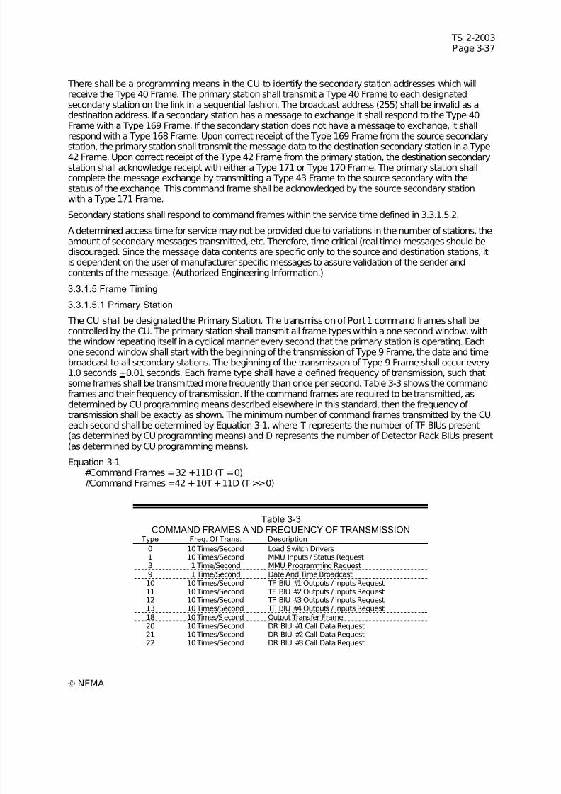
7/30/2019 NEMA TS2-2003- Traffic Controller Assemb
http://slidepdf.com/reader/full/nema-ts2-2003-traffic-controller-assemb 101/246
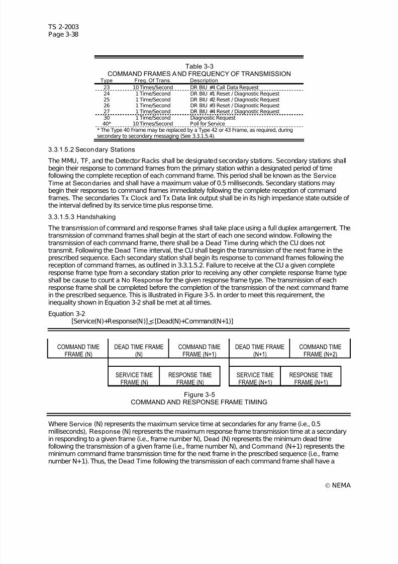
7/30/2019 NEMA TS2-2003- Traffic Controller Assemb
http://slidepdf.com/reader/full/nema-ts2-2003-traffic-controller-assemb 102/246
TS 2-2003Page 3-38
© NEMA
Table 3-3COMMAND FRAMES AND FREQUENCY OF TRANSMISSION
Type Freq. Of Trans. Description
23 10 Times/Second DR BIU #4 Call Data Request24 1 Time/Second DR BIU #1 Reset / Diagnostic Request
25 1 Time/Second DR BIU #2 Reset / Diagnostic Request26 1 Time/Second DR BIU #3 Reset / Diagnostic Request27 1 Time/Second DR BIU #4 Reset / Diagnostic Request30 1 Time/Second Diagnostic Request40* 10 Times/Second Poll for Service
* The Type 40 Frame may be replaced by a Type 42 or 43 Frame, as required, duringsecondary to secondary messaging (See 3.3.1.5.4).
3.3.1.5.2 Secondary Stations
The MMU, TF, and the Detector Racks shall be designated secondary stations. Secondary stations shallbegin their response to command frames from the primary station within a designated period of timefollowing the complete reception of each command frame. This period shall be known as the ServiceTime at Secondaries and shall have a maximum value of 0.5 milliseconds. Secondary stations maybegin their responses to command frames immediately following the complete reception of command
frames. The secondaries Tx Clock and Tx Data link output shall be in its high impedance state outside of the interval defined by its service time plus response time.
3.3.1.5.3 Handshaking
The transmission of command and response frames shall take place using a full duplex arrangement. Thetransmission of command frames shall begin at the start of each one second window. Following thetransmission of each command frame, there shall be a Dead Time during which the CU does nottransmit. Following the Dead Time interval, the CU shall begin the transmission of the next frame in theprescribed sequence. Each secondary station shall begin its response to command frames following thereception of command frames, as outlined in 3.3.1.5.2. Failure to receive at the CU a given completeresponse frame type from a secondary station prior to receiving any other complete response frame typeshall be cause to count a No Response for the given response frame type. The transmission of eachresponse frame shall be completed before the completion of the transmission of the next command frame
in the prescribed sequence. This is illustrated in Figure 3-5. In order to meet this requirement, theinequality shown in Equation 3-2 shall be met at all times.
Equation 3-2[Service(N)+Response(N)] <[Dead(N)+Command(N+1)]
COMMAND TIMEFRAME (N)
DEAD TIME FRAME(N)
COMMAND TIMEFRAME (N+1)
DEAD TIME FRAME(N+1)
COMMAND TIMEFRAME (N+2)
SERVICE TIMEFRAME (N)
RESPONSE TIMEFRAME (N)
SERVICE TIMEFRAME (N+1)
RESPONSE TIMEFRAME (N+1)
Figure 3-5COMMAND AND RESPONSE FRAME TIMING
Where Service (N) represents the maximum service time at secondaries for any frame (i.e., 0.5milliseconds), Response (N) represents the maximum response frame transmission time at a secondaryin responding to a given frame (i.e., frame number N), Dead (N) represents the minimum dead timefollowing the transmission of a given frame (i.e., frame number N), and Command (N+1) represents theminimum command frame transmission time for the next frame in the prescribed sequence (i.e., framenumber N+1). Thus, the Dead Time following the transmission of each command frame shall have a
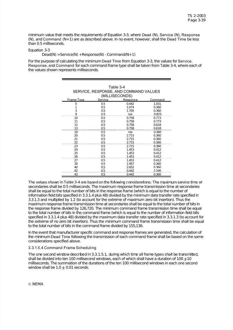
7/30/2019 NEMA TS2-2003- Traffic Controller Assemb
http://slidepdf.com/reader/full/nema-ts2-2003-traffic-controller-assemb 103/246
TS 2-2003Page 3-39
© NEMA
minimum value that meets the requirements of Equation 3-3, where Dead (N), Service (N), Response (N), and Command (N+1) are as described above. In no event, however, shall the Dead Time be lessthan 0.5 milliseconds.
Equation 3-3Dead(N) =Service(N) +Response(N) - Command(N+1)
For the purpose of calculating the minimumDead Time from Equation 3-3, the values for Service,Response, and Command for each command frame type shall be taken from Table 3-4, where each of the values shown represents milliseconds.
Table 3-4SERVICE, RESPONSE, AND COMMAND VALUES
(MILLISECONDS) Frame Type Service Response Command
0 0.5 0.442 1.0311 0.5 1.074 0.3603 0.5 1.705 0.360
9 0.5 n/a 0.82510 0.5 0.758 0.77311 0.5 0.758 0.77312 0.5 0.758 0.61813 0.5 0.758 0.61818 0.5 n/a 0.36020 0.5 2.715 0.36021 0.5 2.715 0.36022 0.5 2.715 0.36023 0.5 2.715 0.36024 0.5 1.453 0.41225 0.5 1.453 0.41226 0.5 1.453 0.41227 0.5 1.453 0.41230 0.5 1.957 0.36040 0.5 2.652 0.36042 0.5 0.442 2.166
43 0.5 0.442 0.360
The values shown in Table 3-4 are based on the following considerations: The maximum service time atsecondaries shall be 0.5 milliseconds. The maximum response frame transmission time at secondariesshall be equal to the total number of bits in the response frame (which is equal to the number of information field bits specified in 3.3.1.4 plus 48) divided by the minimum data transfer rate specified in3.3.1.3 and multiplied by 1.2 (to account for the extreme of maximum zero bit insertion). Thus themaximum response frame transmission time at secondaries shall be equal to the total number of bits inthe response frame divided by 126,720. The minimum command frame transmission time shall be equalto the total number of bits in the command frame (which is equal to the number of information field bitsspecified in 3.3.1.4 plus 48) divided by the maximum data transfer rate specified in 3.3.1.3 (to account forthe extreme of no zero bit insertion). Thus the minimum command frame transmission time shall be equalto the total number of bits in the command frame divided by 155,136.
In the event that manufacturer specific command and response frames are generated, the calculation of the minimumDead Time following the transmission of each command frame shall be based on the sameconsiderations specified above.
3.3.1.5.4 Command Frame Scheduling
The one second window described in 3.3.1.5.1, during which time all frame types shall be transmitted,shall be divided into ten 100 millisecond windows, each of which shall have a duration of 100 +10milliseconds. The summation of the durations of the ten 100 millisecond windows in each one secondwindow shall be 1.0 + 0.01 seconds.
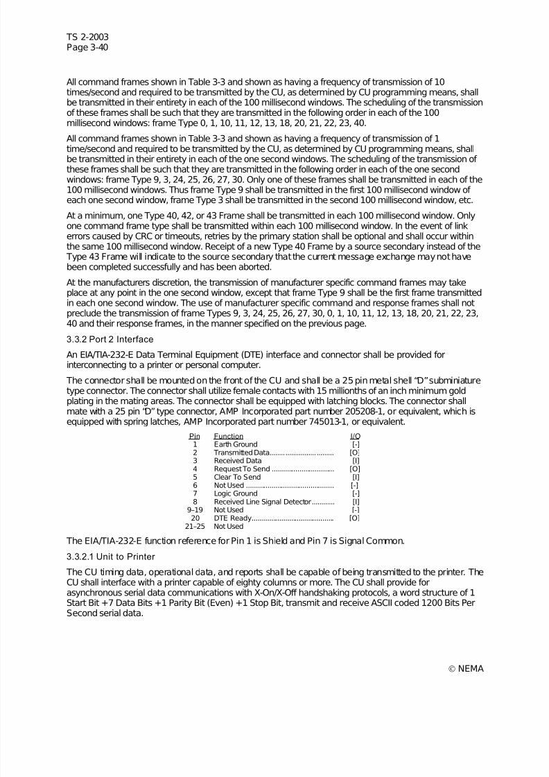
7/30/2019 NEMA TS2-2003- Traffic Controller Assemb
http://slidepdf.com/reader/full/nema-ts2-2003-traffic-controller-assemb 104/246
TS 2-2003Page 3-40
© NEMA
All command frames shown in Table 3-3 and shown as having a frequency of transmission of 10times/second and required to be transmitted by the CU, as determined by CU programming means, shallbe transmitted in their entirety in each of the 100 millisecond windows. The scheduling of the transmissionof these frames shall be such that they are transmitted in the following order in each of the 100millisecond windows: frame Type 0, 1, 10, 11, 12, 13, 18, 20, 21, 22, 23, 40.
All command frames shown in Table 3-3 and shown as having a frequency of transmission of 1time/second and required to be transmitted by the CU, as determined by CU programming means, shallbe transmitted in their entirety in each of the one second windows. The scheduling of the transmission of these frames shall be such that they are transmitted in the following order in each of the one secondwindows: frame Type 9, 3, 24, 25, 26, 27, 30. Only one of these frames shall be transmitted in each of the100 millisecond windows. Thus frame Type 9 shall be transmitted in the first 100 millisecond window of each one second window, frame Type 3 shall be transmitted in the second 100 millisecond window, etc.
At a minimum, one Type 40, 42, or 43 Frame shall be transmitted in each 100 millisecond window. Onlyone command frame type shall be transmitted within each 100 millisecond window. In the event of linkerrors caused by CRC or timeouts, retries by the primary station shall be optional and shall occur withinthe same 100 millisecond window. Receipt of a new Type 40 Frame by a source secondary instead of the Type 43 Frame will indicate to the source secondary that the current message exchange may not havebeen completed successfully and has been aborted.
At the manufacturers discretion, the transmission of manufacturer specific command frames may takeplace at any point in the one second window, except that frame Type 9 shall be the first frame transmittedin each one second window. The use of manufacturer specific command and response frames shall notpreclude the transmission of frame Types 9, 3, 24, 25, 26, 27, 30, 0, 1, 10, 11, 12, 13, 18, 20, 21, 22, 23,40 and their response frames, in the manner specified on the previous page.
3.3.2 Port 2 Interface
An EIA/TIA-232-E Data Terminal Equipment (DTE) interface and connector shall be provided forinterconnecting to a printer or personal computer.
The connector shall be mounted on the front of the CU and shall be a 25 pin metal shell “D” subminiaturetype connector. The connector shall utilize female contacts with 15 millionths of an inch minimum goldplating in the mating areas. The connector shall be equipped with latching blocks. The connector shallmate with a 25 pin “D” type connector, AMP Incorporated part number 205208-1, or equivalent, which isequipped with spring latches, AMP Incorporated part number 745013-1, or equivalent.
Pin Function I/O1 Earth Ground [-]2 Transmitted Data................................. [O]3 Received Data [I]4 Request To Send ................................ [O]5 Clear To Send [I]6 Not Used ............................................. [-]7 Logic Ground [-]8 Received Line Signal Detector............ [I]
9–19 Not Used [-]20 DTE Ready.......................................... [O]
21–25 Not Used
The EIA/TIA-232-E function reference for Pin 1 is Shield and Pin 7 is Signal Common.3.3.2.1 Unit to Printer
The CU timing data, operational data, and reports shall be capable of being transmitted to the printer. TheCU shall interface with a printer capable of eighty columns or more. The CU shall provide forasynchronous serial data communications with X-On/X-Off handshaking protocols, a word structure of 1Start Bit +7 Data Bits +1 Parity Bit (Even) +1 Stop Bit, transmit and receive ASCII coded 1200 Bits PerSecond serial data.
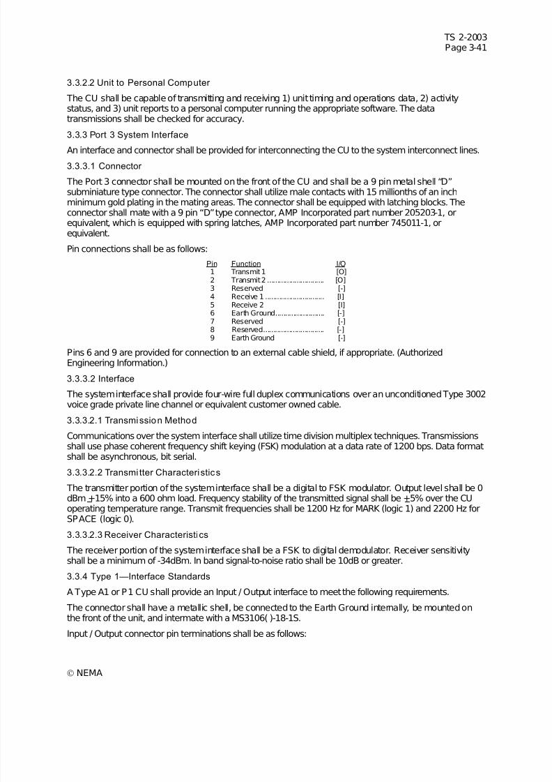
7/30/2019 NEMA TS2-2003- Traffic Controller Assemb
http://slidepdf.com/reader/full/nema-ts2-2003-traffic-controller-assemb 105/246
TS 2-2003Page 3-41
© NEMA
3.3.2.2 Unit to Personal Computer
The CU shall be capable of transmitting and receiving 1) unit timing and operations data, 2) activitystatus, and 3) unit reports to a personal computer running the appropriate software. The datatransmissions shall be checked for accuracy.
3.3.3 Port 3 System InterfaceAn interface and connector shall be provided for interconnecting the CU to the system interconnect lines.
3.3.3.1 Connector
The Port 3 connector shall be mounted on the front of the CU and shall be a 9 pin metal shell “D”subminiature type connector. The connector shall utilize male contacts with 15 millionths of an inchminimum gold plating in the mating areas. The connector shall be equipped with latching blocks. Theconnector shall mate with a 9 pin “D” type connector, AMP Incorporated part number 205203-1, orequivalent, which is equipped with spring latches, AMP Incorporated part number 745011-1, orequivalent.
Pin connections shall be as follows:
Pin Function I/O
1 Transmit 1 [O]2 Transmit 2 ............................. [O]3 Reserved [-]4 Receive 1 .............................. [I]5 Receive 2 [I]6 Earth Ground......................... [-]7 Reserved [-]8 Reserved............................... [-]9 Earth Ground [-]
Pins 6 and 9 are provided for connection to an external cable shield, if appropriate. (AuthorizedEngineering Information.)
3.3.3.2 Interface
The system interface shall provide four-wire full duplex communications over an unconditioned Type 3002voice grade private line channel or equivalent customer owned cable.
3.3.3.2.1 Transmission Method
Communications over the system interface shall utilize time division multiplex techniques. Transmissionsshall use phase coherent frequency shift keying (FSK) modulation at a data rate of 1200 bps. Data formatshall be asynchronous, bit serial.
3.3.3.2.2 Transmi tter Characteristics
The transmitter portion of the system interface shall be a digital to FSK modulator. Output level shall be 0dBm +15% into a 600 ohm load. Frequency stability of the transmitted signal shall be +5% over the CUoperating temperature range. Transmit frequencies shall be 1200 Hz for MARK (logic 1) and 2200 Hz forSPACE (logic 0).
3.3.3.2.3 Receiver Characteristics
The receiver portion of the system interface shall be a FSK to digital demodulator. Receiver sensitivityshall be a minimum of -34dBm. In band signal-to-noise ratio shall be 10dB or greater.
3.3.4 Type 1—Interface Standards
A Type A1 or P1 CU shall provide an Input / Output interface to meet the following requirements.
The connector shall have a metallic shell, be connected to the Earth Ground internally, be mounted onthe front of the unit, and intermate with a MS3106( )-18-1S.
Input / Output connector pin terminations shall be as follows:

7/30/2019 NEMA TS2-2003- Traffic Controller Assemb
http://slidepdf.com/reader/full/nema-ts2-2003-traffic-controller-assemb 106/246
TS 2-2003Page 3-42
© NEMA
Connector “ A” Pin/FunctionPin Function I/OA AC Neutral [I]B Not Used ...............................C AC Line [I]D Not Used ...............................
E Not UsedF Fault Monitor......................... [O]G Logic Ground [O]H Earth Ground......................... [I]I Not Used
J Not Used...............................
3.3.5 Type 2—Interface Standards
A Type A2 or P2 CU shall provide an Input / Output interface to meet the following requirements.
3.3.5.1 Electrical Limits of Input / Output Terminations
3.3.5.1.1 Logic Levels
All logic signals (except as explicitly defined elsewhere in these standards) shall be Low state (nominal 0volts) for the True (operate) state of all input and output terminations. Input / Output terminations, when
not activated, shall be internally biased to the False (High) nonoperate state (+24 volts DC).
3.3.5.1.2 Transient Immuni ty
The operation of the CU shall not be affected during operation by the application to any input or outputterminal of pulses of 10 microseconds duration, 300-volt positive or negative amplitude, and with amaximum repetition rate of 1 pulse per second. For the purposes of this requirement, a pulse sourcehaving an output impedance of not less than 1K ohms, nor greater than 10K ohms shall be used.
3.3.5.1.3 Inputs
Inputs shall have the following characteristics:
1. A voltage between 0 and 8 volts shall be considered the Low state.
2. A voltage greater than 16 volts shall be considered the High state.
3. The transition from the Low state to High state (and vice versa) shall occur between 8 and 16 volts.
4. External transition from the Low state to High state (and vice versa) shall be accomplished within 0.1millisecond.
5. Over the voltage range 0 to 26 volts DC, the maximum current In orOut of any input control terminalshall be less than 10 milliamperes. Input impedance shall not exceed 11K ohms to 24 volts DC, norshall the surge impedance be less than 100 ohms resistive.
6. Any input signal dwelling in a defined logic state for less than 8 milliseconds shall not be recognized.Any input signal dwelling in a defined logic state for more than 17 milliseconds shall be recognized.Successive similar logic state transitions shall not be recognized when occurring less than 8milliseconds apart, and shall be recognized when occurring more than 34 milliseconds apart.
3.3.5.1.4 Outputs
Electrical outputs shall have the following characteristics:
1. Output Circuits
a. The Low (operate) voltage shall be between 0 and 4 volts.
b. Current sinking capability in the Low state (True) shall be at least 200 milliamperes from aninductive load.
c. With an external impedance of 100K ohms or greater, the transition from 4 to 16 volts (and viceversa) shall be accomplished within 0.1 millisecond.
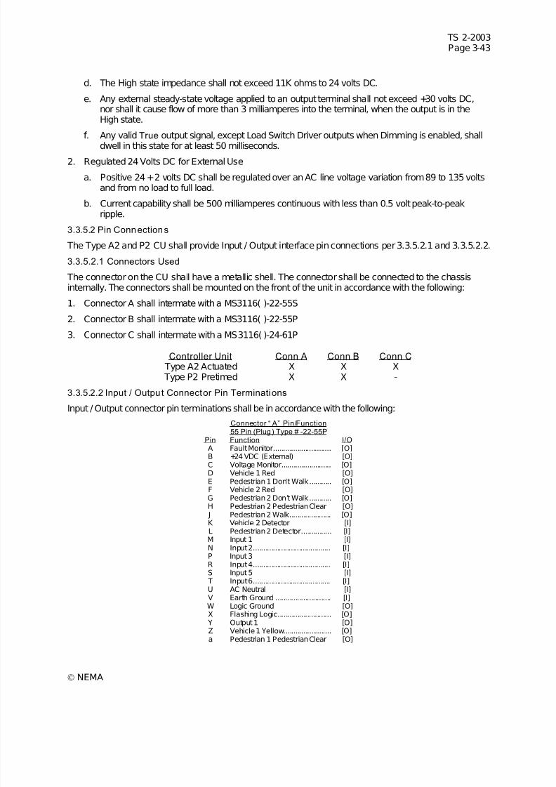
7/30/2019 NEMA TS2-2003- Traffic Controller Assemb
http://slidepdf.com/reader/full/nema-ts2-2003-traffic-controller-assemb 107/246
TS 2-2003Page 3-43
© NEMA
d. The High state impedance shall not exceed 11K ohms to 24 volts DC.
e. Any external steady-state voltage applied to an output terminal shall not exceed +30 volts DC,nor shall it cause flow of more than 3 milliamperes into the terminal, when the output is in theHigh state.
f. Any valid True output signal, except Load Switch Driver outputs when Dimming is enabled, shalldwell in this state for at least 50 milliseconds.
2. Regulated 24 Volts DC for External Use
a. Positive 24 +2 volts DC shall be regulated over an AC line voltage variation from 89 to 135 voltsand from no load to full load.
b. Current capability shall be 500 milliamperes continuous with less than 0.5 volt peak-to-peakripple.
3.3.5.2 Pin Connections
The Type A2 and P2 CU shall provide Input / Output interface pin connections per 3.3.5.2.1 and 3.3.5.2.2.
3.3.5.2.1 Connectors Used
The connector on the CU shall have a metallic shell. The connector shall be connected to the chassisinternally. The connectors shall be mounted on the front of the unit in accordance with the following:
1. Connector A shall intermate with a MS3116( )-22-55S
2. Connector B shall intermate with a MS3116( )-22-55P
3. Connector C shall intermate with a MS3116( )-24-61P
Controller Unit Conn A Conn B Conn C Type A2 Actuated X X X Type P2 Pretimed X X -
3.3.5.2.2 Input / Output Connector Pin Terminations
Input / Output connector pin terminations shall be in accordance with the following:
Connector “ A” Pin/Function55 Pin (Plug) Type # -22-55P
Pin Function I/OA Fault Monitor............................. [O]B +24 VDC (External) [O]C Voltage Monitor......................... [O]D Vehicle 1 Red [O]E Pedestrian 1 Don’t Walk........... [O]F Vehicle 2 Red [O]G Pedestrian 2 Don’t Walk........... [O]H Pedestrian 2 Pedestrian Clear [O] J Pedestrian 2 Walk..................... [O]K Vehicle 2 Detector [I]L Pedestrian 2 Detector............... [I]M Input 1 [I]
N Input 2....................................... [I]P Input 3 [I]R Input 4....................................... [I]S Input 5 [I] T Input 6....................................... [I]U AC Neutral [I]V Earth Ground ............................ [I]W Logic Ground [O]X Flashing Logic........................... [O]
Y Output 1 [O]Z Vehicle 1 Yellow........................ [O]a Pedestrian 1 Pedestrian Clear [O]
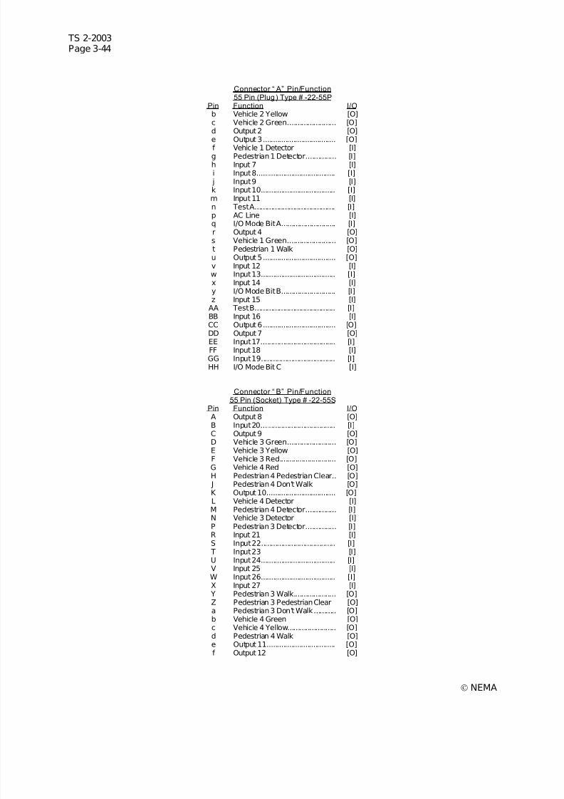
7/30/2019 NEMA TS2-2003- Traffic Controller Assemb
http://slidepdf.com/reader/full/nema-ts2-2003-traffic-controller-assemb 108/246
TS 2-2003Page 3-44
© NEMA
Connector “ A” Pin/Function55 Pin (Plug) Type # -22-55P
Pin Function I/Ob Vehicle 2 Yellow [O]c Vehicle 2 Green........................ [O]d Output 2 [O]
e Output 3.................................... [O]f Vehicle 1 Detector [I]g Pedestrian 1 Detector............... [I]h Input 7 [I]i Input 8....................................... [I]
j Input 9 [I]k Input 10..................................... [I]m Input 11 [I]n Test A........................................ [I]p AC Line [I]q I/O Mode Bit A........................... [I]r Output 4 [O]s Vehicle 1 Green........................ [O]t Pedestrian 1 Walk [O]u Output 5.................................... [O]v Input 12 [I]w Input 13..................................... [I]x Input 14 [I]y I/O Mode Bit B........................... [I]z Input 15 [I]
AA Test B........................................ [I]BB Input 16 [I]CC Output 6.................................... [O]DD Output 7 [O]EE Input 17..................................... [I]FF Input 18 [I]GG Input 19..................................... [I]HH I/O Mode Bit C [I]
Connector “ B” Pin/Function55 Pin (Socket) Type # -22-55S
Pin Function I/O
A Output 8 [O]B Input 20..................................... [I]C Output 9 [O]D Vehicle 3 Green........................ [O]E Vehicle 3 Yellow [O]F Vehicle 3 Red............................ [O]G Vehicle 4 Red [O]H Pedestrian 4 Pedestrian Clear.. [O] J Pedestrian 4 Don’t Walk [O]K Output 10.................................. [O]L Vehicle 4 Detector [I]M Pedestrian 4 Detector............... [I]N Vehicle 3 Detector [I]P Pedestrian 3 Detector............... [I]R Input 21 [I]S Input 22..................................... [I] T Input 23 [I]
U Input 24..................................... [I]V Input 25 [I]W Input 26..................................... [I]X Input 27 [I]
Y Pedestrian 3 Walk..................... [O]Z Pedestrian 3 Pedestrian Clear [O]a Pedestrian 3 Don’t Walk........... [O]b Vehicle 4 Green [O]c Vehicle 4 Yellow........................ [O]d Pedestrian 4 Walk [O]e Output 11.................................. [O]f Output 12 [O]
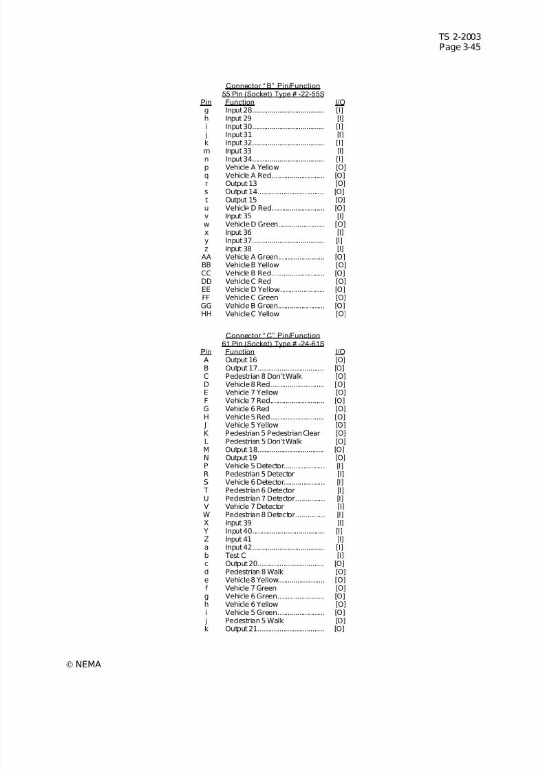
7/30/2019 NEMA TS2-2003- Traffic Controller Assemb
http://slidepdf.com/reader/full/nema-ts2-2003-traffic-controller-assemb 109/246
TS 2-2003Page 3-45
© NEMA
Connector “ B” Pin/Function55 Pin (Socket) Type # -22-55S
Pin Function I/Og Input 28..................................... [I]h Input 29 [I]i Input 30..................................... [I]
j Input 31 [I]k Input 32..................................... [I]m Input 33 [I]n Input 34..................................... [I]p Vehicle A Yellow [O]q Vehicle A Red........................... [O]r Output 13 [O]s Output 14.................................. [O]t Output 15 [O]u Vehicle D Red........................... [O]v Input 35 [I]w Vehicle D Green........................ [O]x Input 36 [I]y Input 37..................................... [I]z Input 38 [I]
AA Vehicle A Green........................ [O]BB Vehicle B Yellow [O]CC Vehicle B Red........................... [O]DD Vehicle C Red [O]EE Vehicle D Yellow....................... [O]FF Vehicle C Green [O]GG Vehicle B Green........................ [O]HH Vehicle C Yellow [O]
Connector “ C” Pin/Function61 Pin (Socket) Type # -24-61S
Pin Function I/OA Output 16 [O]B Output 17.................................. [O]C Pedestrian 8 Don’t Walk [O]D Vehicle 8 Red............................ [O]E Vehicle 7 Yellow [O]F Vehicle 7 Red............................ [O]G Vehicle 6 Red [O]H Vehicle 5 Red............................ [O] J Vehicle 5 Yellow [O]K Pedestrian 5 Pedestrian Clear [O]L Pedestrian 5 Don’t Walk [O]M Output 18.................................. [O]N Output 19 [O]P Vehicle 5 Detector..................... [I]R Pedestrian 5 Detector [I]S Vehicle 6 Detector..................... [I] T Pedestrian 6 Detector [I]U Pedestrian 7 Detector............... [I]V Vehicle 7 Detector [I]W Pedestrian 8 Detector............... [I]X Input 39 [I]
Y Input 40..................................... [I]
Z Input 41 [I]a Input 42..................................... [I]b Test C [I]c Output 20.................................. [O]d Pedestrian 8 Walk [O]e Vehicle 8 Yellow........................ [O]f Vehicle 7 Green [O]g Vehicle 6 Green........................ [O]h Vehicle 6 Yellow [O]i Vehicle 5 Green........................ [O]
j Pedestrian 5 Walk [O]k Output 21.................................. [O]
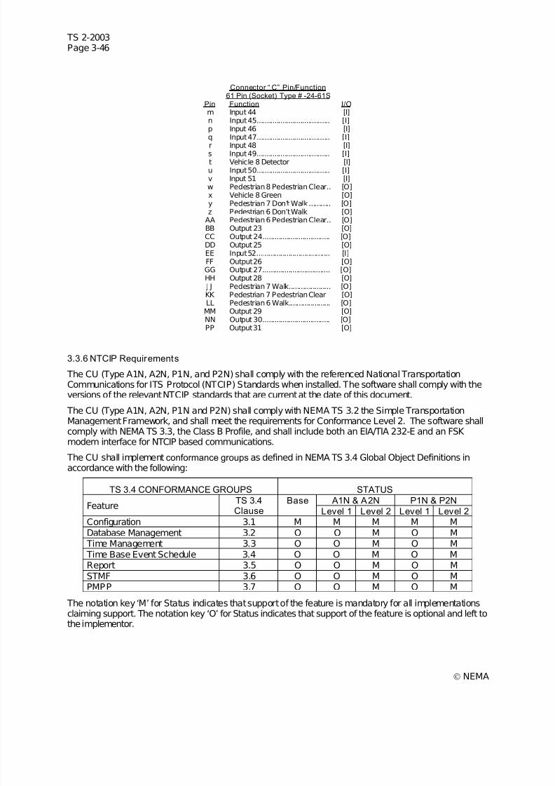
7/30/2019 NEMA TS2-2003- Traffic Controller Assemb
http://slidepdf.com/reader/full/nema-ts2-2003-traffic-controller-assemb 110/246
TS 2-2003Page 3-46
© NEMA
Connector “ C” Pin/Function61 Pin (Socket) Type # -24-61S
Pin Function I/Om Input 44 [I]n Input 45..................................... [I]p Input 46 [I]
q Input 47..................................... [I]r Input 48 [I]s Input 49..................................... [I]t Vehicle 8 Detector [I]u Input 50..................................... [I]v Input 51 [I]w Pedestrian 8 Pedestrian Clear.. [O]x Vehicle 8 Green [O]y Pedestrian 7 Don’t Walk........... [O]z Pedestrian 6 Don’t Walk [O]
AA Pedestrian 6 Pedestrian Clear.. [O]BB Output 23 [O]CC Output 24.................................. [O]DD Output 25 [O]EE Input 52..................................... [I]FF Output 26 [O]GG Output 27.................................. [O]HH Output 28 [O] J J Pedestrian 7 Walk..................... [O]KK Pedestrian 7 Pedestrian Clear [O]LL Pedestrian 6 Walk..................... [O]MM Output 29 [O]NN Output 30.................................. [O]PP Output 31 [O]
3.3.6 NTCIP Requirements
The CU (Type A1N, A2N, P1N, and P2N) shall comply with the referenced National TransportationCommunications for ITS Protocol (NTCIP) Standards when installed. The software shall comply with theversions of the relevant NTCIP standards that are current at the date of this document.
The CU (Type A1N, A2N, P1N and P2N) shall comply with NEMA TS 3.2 the Simple TransportationManagement Framework, and shall meet the requirements for Conformance Level 2. The software shallcomply with NEMA TS 3.3, the Class B Profile, and shall include both an EIA/TIA 232-E and an FSK modem interface for NTCIP based communications.
The CU shall implement conformance groups as defined in NEMA TS 3.4 Global Object Definitions inaccordance with the following:
TS 3.4 CONFORMANCE GROUPS STATUS
A1N & A2N P1N & P2NFeature
TS 3.4Clause
Base
Level 1 Level 2 Level 1 Level 2
Configuration 3.1 M M M M MDatabase Management 3.2 O O M O M Time Management 3.3 O O M O M Time Base Event Schedule 3.4 O O M O MReport 3.5 O O M O MSTMF 3.6 O O M O MPMPP 3.7 O O M O M
The notation key ‘M’ for Status indicates that support of the feature is mandatory for all implementationsclaiming support. The notation key ‘O’ for Status indicates that support of the feature is optional and left tothe implementor.
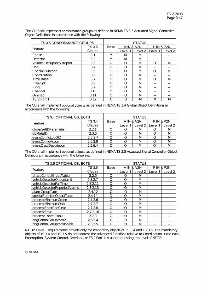
7/30/2019 NEMA TS2-2003- Traffic Controller Assemb
http://slidepdf.com/reader/full/nema-ts2-2003-traffic-controller-assemb 111/246
TS 2-2003Page 3-47
© NEMA
The CU shall implement conformance groups as defined in NEMA TS 3.5 Actuated Signal ControllerObject Definitions in accordance with the following:
TS 3.5 CONFORMANCE GROUPS STATUS
A1N & A2N P1N & P2NFeature
TS 3.5
Clause
Base
Level 1 Level 2 Level 1 Level 2Phase 3.1 M M M -- --Detector 3.2 M M M -- --Volume Occupancy Report 3.3 O O M O MUnit 3.4 O O M -- --Special Function 3.5 O O M O MCoordination 3.6 O O M -- -- Time Base 3.7 O O M O MPreempt 3.8 O O M -- --Ring 3.9 O O M -- --Channel 3.10 O O M -- --Overlap 3.11 O O M -- -- TS 2 Port 1 3.12 O O M 0 M
The CU shall implement optional objects as defined in NEMA TS 3.4 Global Object Definitions inaccordance with the following:
TS 3.4 OPTIONAL OBJECTS STATUS
A1N & A2N P1N & P2NFeature
TS 3.4Clause
Base
Level 1 Level 2 Level 1 Level 2
globalSetIDParameter 2.2.1 O O M O MdbMakeID 2.3.5 O O M O MeventConfigLogOID 2.5.2.7 O O M O MeventConfigAction 2.5.2.8 O O M O MeventClassDescription 2.5.6.4 O O M O M
The CU shall implement optional objects as defined in NEMA TS 3.5 Actuated Signal Controller ObjectDefinitions in accordance with the following:
TS 3.5 OPTIONAL OBJECTS STATUS
A1N & A2N P1N & P2NFeature
TS 3.5Clause
Base
Level 1 Level 2 Level 1 Level 2
phaseControlGroupTable 2.2.5 O O M -- --vehicleDetectorQueueLimit 2.3.2.7 O O M -- --vehicleDetectorFailTime 2.3.2.11 O O M -- --vehicleDetectorReportedAlarms 2.3.2.13 O O M -- --alarmGroupTable 2.4.12 O O M -- --specialFunctionOutputTable 2.4.14 O O M -- --preemptMinimumGreen 2.7.2.6 O O M -- --
preemptMinimumWalk 2.7.2.7 O O M -- --preemptEnterPedClear 2.7.2.8 O O M -- --preemptState 2.7.2.16 O O M -- --preemptControlTable 2.7.3 O O M -- --ringControlGroupMax2 2.8.5.4 O O M -- --ringControlGroupMaxInhibit 2.8.5.5 O O M -- --
NTCIP Level 1 requirements provide only the mandatory objects of TS 3.4 and TS 3.5. The mandatoryobjects of TS 3.4 and TS 3.5 do not address the advanced functions relative to Coordination, Time Base,Preemption, System Control, Overlaps, or TS 2 Port 1. A user requesting this level of NTCIP
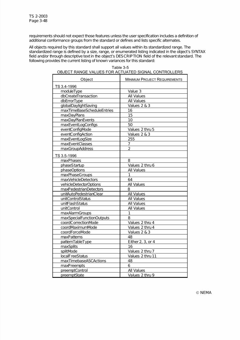
7/30/2019 NEMA TS2-2003- Traffic Controller Assemb
http://slidepdf.com/reader/full/nema-ts2-2003-traffic-controller-assemb 112/246
TS 2-2003Page 3-48
© NEMA
requirements should not expect those features unless the user specification includes a definition of additional conformance groups from the standard or defines and lists specific alternates.
All objects required by this standard shall support all values within its standardized range. Thestandardized range is defined by a size, range, or enumerated listing indicated in the object’s SYNTAXfield and/or through descriptive text in the object’s DESCRIPTION field of the relevant standard. The
following provides the current listing of known variances for this standard:
Table 3-5OBJECT RANGE VALUES FOR ACTUATED SIGNAL CONTROLLERS
Object MINIMUM PROJECT REQUIREMENTS
TS 3.4-1996 moduleType Value 3dbCreateTransaction All ValuesdbErrorType All ValuesglobalDaylightSaving Values 2 & 3maxTimeBaseScheduleEntries 16maxDayPlans 15
maxDayPlanEvents 10maxEventLogConfigs 50eventConfigMode Values 2 thru 5eventConfigAction Values 2 & 3maxEventLogSize 255maxEventClasses 7maxGroupAddress 2
TS 3.5-1996 maxPhases 8phaseStartup Values 2 thru 6phaseOptions All ValuesmaxPhaseGroups 1
maxVehicleDetectors 64vehicleDetectorOptions All ValuesmaxPedestrianDetectors 8unitAutoPedestrianClear All ValuesunitControlStatus All ValuesunitFlashStatus All ValuesunitControl All ValuesmaxAlarmGroups 1maxSpecialFunctionOutputs 8coordCorrectionMode Values 2 thru 4coordMaximumMode Values 2 thru 4coordForceMode Values 2 & 3
maxPatterns 48patternTableType Either 2, 3, or 4maxSplits 16splitMode Values 2 thru 7localFreeStatus Values 2 thru 11maxTimebaseASCActions 48maxPreempts 6preemptControl All ValuespreemptState Values 2 thru 9
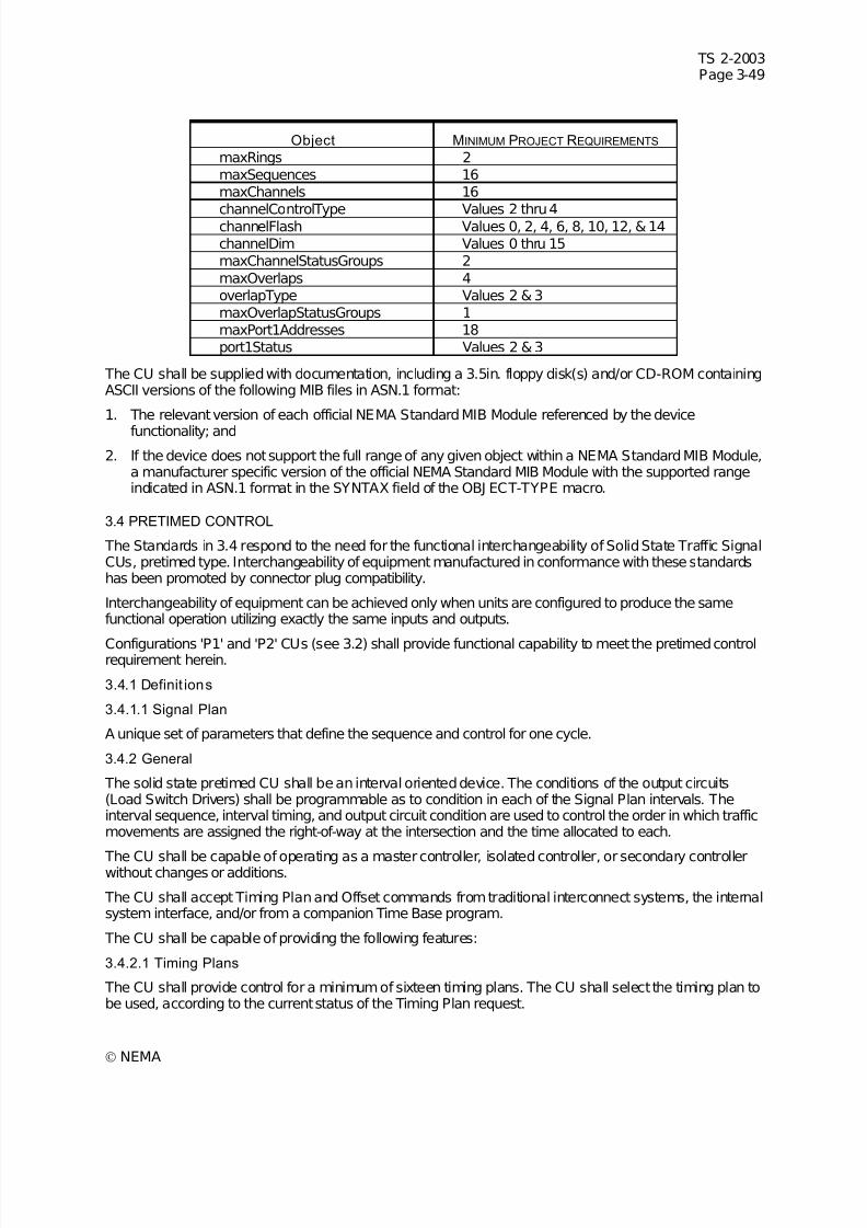
7/30/2019 NEMA TS2-2003- Traffic Controller Assemb
http://slidepdf.com/reader/full/nema-ts2-2003-traffic-controller-assemb 113/246
TS 2-2003Page 3-49
© NEMA
Object MINIMUM PROJECT REQUIREMENTS
maxRings 2maxSequences 16maxChannels 16
channelControlType Values 2 thru 4channelFlash Values 0, 2, 4, 6, 8, 10, 12, & 14channelDim Values 0 thru 15maxChannelStatusGroups 2maxOverlaps 4overlapType Values 2 & 3maxOverlapStatusGroups 1maxPort1Addresses 18port1Status Values 2 & 3
The CU shall be supplied with documentation, including a 3.5in. floppy disk(s) and/or CD-ROM containingASCII versions of the following MIB files in ASN.1 format:
1. The relevant version of each official NEMA Standard MIB Module referenced by the device
functionality; and
2. If the device does not support the full range of any given object within a NEMA Standard MIB Module,a manufacturer specific version of the official NEMA Standard MIB Module with the supported rangeindicated in ASN.1 format in the SYNTAX field of the OBJ ECT-TYPE macro.
3.4 PRETIMED CONTROL
The Standards in 3.4 respond to the need for the functional interchangeability of Solid State Traffic SignalCUs, pretimed type. Interchangeability of equipment manufactured in conformance with these standardshas been promoted by connector plug compatibility.
Interchangeability of equipment can be achieved only when units are configured to produce the samefunctional operation utilizing exactly the same inputs and outputs.
Configurations 'P1' and 'P2' CUs (see 3.2) shall provide functional capability to meet the pretimed controlrequirement herein.
3.4.1 Definit ions
3.4.1.1 Signal Plan
A unique set of parameters that define the sequence and control for one cycle.
3.4.2 General
The solid state pretimed CU shall be an interval oriented device. The conditions of the output circuits(Load Switch Drivers) shall be programmable as to condition in each of the Signal Plan intervals. Theinterval sequence, interval timing, and output circuit condition are used to control the order in which trafficmovements are assigned the right-of-way at the intersection and the time allocated to each.
The CU shall be capable of operating as a master controller, isolated controller, or secondary controllerwithout changes or additions.
The CU shall accept Timing Plan and Offset commands from traditional interconnect systems, the internalsystem interface, and/or from a companion Time Base program.
The CU shall be capable of providing the following features:
3.4.2.1 Timing Plans
The CU shall provide control for a minimum of sixteen timing plans. The CU shall select the timing plan tobe used, according to the current status of the Timing Plan request.

7/30/2019 NEMA TS2-2003- Traffic Controller Assemb
http://slidepdf.com/reader/full/nema-ts2-2003-traffic-controller-assemb 114/246
TS 2-2003Page 3-50
© NEMA
3.4.2.1.1 Cycles
The CU shall be capable of providing a minimum of one cycle length for each timing plan. Each cyclelength shall be adjustable over a range of 30 to 255 seconds in 1 second increments.
3.4.2.1.2 Splits
The CU shall be capable of providing a minimum of one set of splits for each timing plan. Each split shallprovide an adjustable time for each interval in the sequence in accordance with the following:
a. 0 to 25.5 seconds in 0.1 second increments, and
b. 0 to 255 seconds in 1 second increments, or
c. 0 to 99 percent (of cycle length) in 1% increments.
3.4.2.2 Intervals
The CU shall be capable of providing a minimum of 24 intervals per Timing Plan. When less than 24intervals are required, it shall be possible to program only the number used.
3.4.2.3 Signal Plans
The CU shall be capable of implementing four different signal plans. All signal plans shall have the samenumber of intervals.
Signal plans shall be capable of being selected based on program entry, interconnect inputs, time basecontrol events, and a system interface.
The CU shall provide the following capability within each signal plan:
3.4.2.3.1 Minimum Time
Means shall be provided, for user definition, of a Minimum Time for each interval (0 to 25.5 seconds in 0.1second increments).
3.4.2.3.2 Load Switch Driver Condit ion
Means shall be provided, for user definition, of the output condition (Green, Yellow, or Red) of eachVehicle Load Switch Driver Group for each interval. A circuit closure to Logic Ground shall bemaintained at one of these three outputs at all times. The three outputs shall energize the appropriatevehicle signal load switching circuit to result in a Green, Yellow, or Red indication for the duration of suchrequired indication.
Means shall be provided, for user definition, of the output condition (Walk, Pedestrian Clear , or Don’tWalk) of each Pedestrian Load Switch Drivers Group for each interval. A circuit closure to Logic Ground shall be maintained on at least one of these three outputs at all times. The three outputs shall energizethe appropriate pedestrian signal load switching circuit to result in a Walk, Pedestrian Clearance, orDon’t Walk indication. The Don’t Walk output shall flash only during the Pedestrian Clearance interval(s).
3.4.2.3.3 Timing Plan Transfer
Means shall be provided, for user definition, of the interval end at which a Timing Plan transfer may occur.
3.4.2.3.4 Signal Plan Transfer
Means shall be provided, for user definition, of the interval end at which a Signal Plan transfer may occur.
3.4.2.3.5 Variable Interval
Means shall be provided, for user definition, of the intervals which shall be considered variable for offsetcorrection, force off, and manual control enable operation.

7/30/2019 NEMA TS2-2003- Traffic Controller Assemb
http://slidepdf.com/reader/full/nema-ts2-2003-traffic-controller-assemb 115/246
TS 2-2003Page 3-51
© NEMA
3.4.2.3.6 Automatic Flash
Means shall be provided, for user definition, of the interval end as the Automatic Flash Entry point and theinterval beginning as the Automatic Flash Exit point.
3.4.2.3.7 Actuated Interval(s)
Means shall be provided, for user definition, of the interval(s) which are serviced based on the activity of vehicle and/or pedestrian detectors.
3.4.2.4 Offset
The CU shall provide three offset settings for each of the Timing Plans.
Each offset shall provide an adjustable interval time in accordance with either of the following:
1. 0 to 254 seconds in 1.0 second increments, or
2. 0 to 99 percent (of cycle length) in 1% increments.
The values shall determine the time in seconds that the starting point of Interval #1, local time zero, shalllag the Synchronization pulse, system time zero.
The CU shall recognize when the sync reference and local offset in control indicate local zero is notcorrect. When establishing its offset based on the sync pulse, the CU shall reference only the leadingedge, regardless of the width of the sync pulse.
3.4.2.5 Sync Monitor
The CU shall monitor the Offset command requests for validity of the imposed sync reference.
The CU shall revert to Free mode when:
1. No sync pulse is received for 3 consecutive cycles.
2. No offset line is active for 15 seconds.
3. More than one offset line is active for 15 seconds.
During Sync Monitor Free mode, the Offset command requests shall continue to be monitored and should
the command request return to valid operation, the CU shall implement the pattern commanded.
The Sync MonitorFree mode may be replaced by a Time Base Control event. See the On-Line definitionin the Time Base section.
3.4.2.6 Manual Contro l
The CU shall be capable of being set to manually operate in any pattern (Timing Plan plus Offset) andSignal Plan via program entry. A manual selection of pattern and signal plan shall override all otherpattern interface commands.
3.4.2.7 Free Mode
The CU shall be capable of Free mode of operation. During this mode all pattern inputs (Timing Plan andOffset) shall be ignored and offset correction shall not occur.
The coordinator shall be capable of being set to the Free mode defined under Sync Monitor and viaprogram entry.
The coordinator shall recognize input requests that conflict with coordinated operation and automaticallyrevert to Free mode while the inputs are active. The inputs that conflict with internal coordination are:
1. Manual Control Enable
2. Stop Time
3. Automatic Flash

7/30/2019 NEMA TS2-2003- Traffic Controller Assemb
http://slidepdf.com/reader/full/nema-ts2-2003-traffic-controller-assemb 116/246
TS 2-2003Page 3-52
© NEMA
4. Any Preemption
3.4.3 Initialization
Initialization shall occur under either of the following conditions:
1. Restoration of power after a defined power interruption.
2. Activation of External Start input.
A program entry for initialization shall be provided to cause the CU to start at the beginning of the definedsignal plan interval.
As part of the initialization routine, calls shall be placed on all actuated movements and retained untilserviced.
3.4.4 Actuated Movements
The CU shall provide actuated operation to the extent that the signal sequence may be dependent onvehicle and/or pedestrian detector actuations.
3.4.4.1 Provision for Storing a Demand
There shall be a provision for storing a call for vehicle service on four vehicle movements when thespecific movement is not displaying a Green indication. The vehicle memory feature shall be capable of being disabled via program entry.
There shall be a provision for storing a call for pedestrian service on each of the four movements, whenthe movement is not displaying a Walk indication.
3.4.4.2 Placement of Vehicle Recall
Means shall be provided, via program entry, to place a recurring demand for vehicle service on themovement when that movement is not in its Green interval.
3.4.4.3 Placement of Pedestr ian Recall
Means shall be provided, via program entry, to place a recurring demand for pedestrian service on themovement when that movement is not in its Walk interval.
3.4.5 External Interface
The CU shall operate with an external interface as follows:
3.4.5.1 Pin Connections
A Type P2 CU shall provide input-output connector pin terminations in accordance with the following:
Connector “ A” Pin/Function55 Pin (Plug) Type # -22-55P
Pin Function I/OA Fault Monitor [O]B +24 VDC (External)................... [O]C Voltage Monitor [O]D Vehicle 1 Red............................ [O]E Pedestrian 1 Don’t Walk [O]F Vehicle 2 Red............................ [O]G Pedestrian 2 Don’t Walk [O]H Pedestrian 2 Pedestrian Clear.. [O] J Pedestrian 2 Walk [O]K Vehicle 2 Detector..................... [I]L Pedestrian 2 Detector [I]M Mode* Input 2............................ [I]N Stop Time [I]P Reserved................................... [I]R External Start [I]S Interval Advance....................... [I] T Ind. Lamp Control [I]
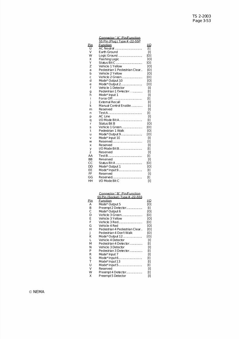
7/30/2019 NEMA TS2-2003- Traffic Controller Assemb
http://slidepdf.com/reader/full/nema-ts2-2003-traffic-controller-assemb 117/246
TS 2-2003Page 3-53
© NEMA
Connector “ A” Pin/Function55 Pin (Plug) Type # -22-55P
Pin Function I/OU AC Neutral ................................ [I]V Earth Ground [I]W Logic Ground ............................ [O]
X Flashing Logic [O] Y Status Bit C ............................... [O]Z Vehicle 1 Yellow [O]a Pedestrian 1 Pedestrian Clear.. [O]b Vehicle 2 Yellow [O]c Vehicle 2 Green........................ [O]d Mode* Output 10 [O]e Mode* Output 2......................... [O]f Vehicle 1 Detector [I]g Pedestrian 1 Detector............... [I]h Mode* Input 1 [I]i Force Off................................... [I]
j External Recall [I]k Manual Control Enable............. [I]m Reserved [I]n Test A........................................ [I]p AC Line [I]q I/O Mode Bit A........................... [I]r Status Bit B [O]s Vehicle 1 Green........................ [O]t Pedestrian 1 Walk [O]u Mode* Output 9......................... [O]v Mode* Input 10 [I]w Reserved................................... [I]x Reserved [I]y I/O Mode Bit B........................... [I]z Reserved [I]
AA Test B........................................ [I]BB Reserved [I]CC Status Bit A ............................... [O]DD Mode* Output 1 [O]EE Mode* Input 9............................ [I]FF Reserved [I]
GG Reserved................................... [I]HH I/O Mode Bit C [I]
Connector “ B” Pin/Function55 Pin (Socket) Type # -22-55S
Pin Function I/OA Mode* Output 5 [O]B Preempt 2 Detector................... [I]C Mode* Output 6 [O]D Vehicle 3 Green........................ [O]E Vehicle 3 Yellow [O]F Vehicle 3 Red............................ [O]G Vehicle 4 Red [O]H Pedestrian 4 Pedestrian Clear.. [O] J Pedestrian 4 Don’t Walk [O]
K Mode* Output 12....................... [O]L Vehicle 4 Detector [I]M Pedestrian 4 Detector............... [I]N Vehicle 3 Detector [I]P Pedestrian 3 Detector............... [I]R Mode* Input 7 [I]S Mode* Input 6............................ [I] T Mode* Input 13 [I]U Mode* Input 5............................ [I]V Reserved [I]W Preempt 4 Detector................... [I]X Preempt 5 Detector [I]
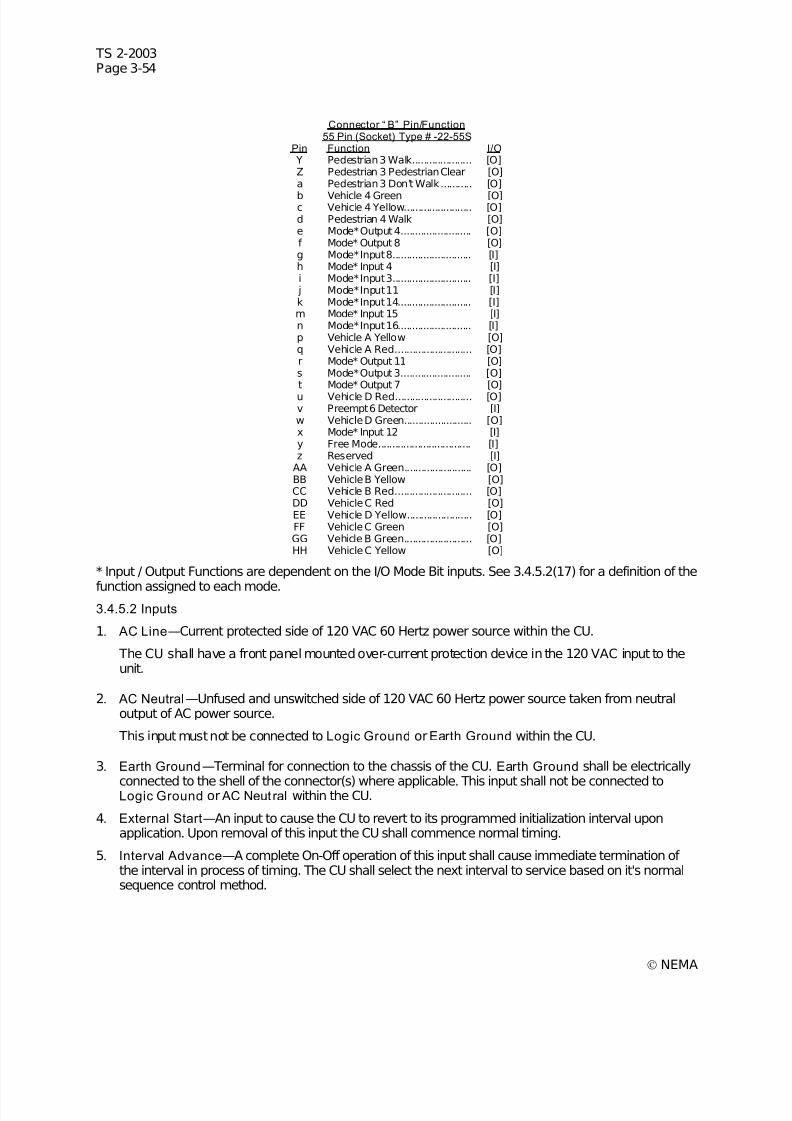
7/30/2019 NEMA TS2-2003- Traffic Controller Assemb
http://slidepdf.com/reader/full/nema-ts2-2003-traffic-controller-assemb 118/246
TS 2-2003Page 3-54
© NEMA
Connector “ B” Pin/Function55 Pin (Socket) Type # -22-55S
Pin Function I/O Y Pedestrian 3 Walk..................... [O]Z Pedestrian 3 Pedestrian Clear [O]a Pedestrian 3 Don’t Walk........... [O]
b Vehicle 4 Green [O]c Vehicle 4 Yellow........................ [O]d Pedestrian 4 Walk [O]e Mode* Output 4......................... [O]f Mode* Output 8 [O]g Mode* Input 8............................ [I]h Mode* Input 4 [I]i Mode* Input 3............................ [I]
j Mode* Input 11 [I]k Mode* Input 14.......................... [I]m Mode* Input 15 [I]n Mode* Input 16.......................... [I]p Vehicle A Yellow [O]q Vehicle A Red........................... [O]r Mode* Output 11 [O]s Mode* Output 3......................... [O]t Mode* Output 7 [O]u Vehicle D Red........................... [O]v Preempt 6 Detector [I]w Vehicle D Green........................ [O]x Mode* Input 12 [I]y Free Mode................................. [I]z Reserved [I]
AA Vehicle A Green........................ [O]BB Vehicle B Yellow [O]CC Vehicle B Red........................... [O]DD Vehicle C Red [O]EE Vehicle D Yellow....................... [O]FF Vehicle C Green [O]GG Vehicle B Green........................ [O]HH Vehicle C Yellow [O]
* Input / Output Functions are dependent on the I/O Mode Bit inputs. See 3.4.5.2(17) for a definition of the
function assigned to each mode.3.4.5.2 Inputs
1. AC Line—Current protected side of 120 VAC 60 Hertz power source within the CU.
The CU shall have a front panel mounted over-current protection device in the 120 VAC input to theunit.
2. AC Neutral—Unfused and unswitched side of 120 VAC 60 Hertz power source taken from neutraloutput of AC power source.
This input must not be connected to Logic Ground orEarth Ground within the CU.
3. Earth Ground—Terminal for connection to the chassis of the CU. Earth Ground shall be electrically
connected to the shell of the connector(s) where applicable. This input shall not be connected toLogic Ground or AC Neutral within the CU.
4. External Start—An input to cause the CU to revert to its programmed initialization interval uponapplication. Upon removal of this input the CU shall commence normal timing.
5. Interval Advance—A complete On-Off operation of this input shall cause immediate termination of the interval in process of timing. The CU shall select the next interval to service based on it's normalsequence control method.
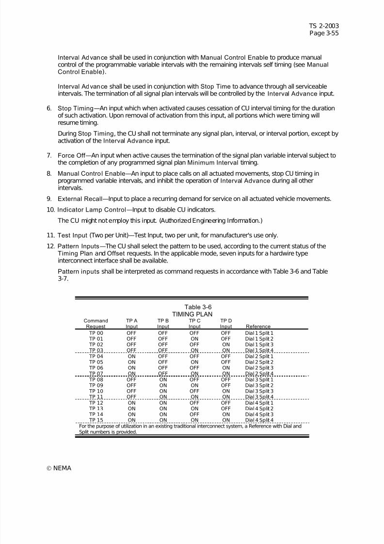
7/30/2019 NEMA TS2-2003- Traffic Controller Assemb
http://slidepdf.com/reader/full/nema-ts2-2003-traffic-controller-assemb 119/246
TS 2-2003Page 3-55
© NEMA
Interval Advance shall be used in conjunction with Manual Control Enable to produce manualcontrol of the programmable variable intervals with the remaining intervals self timing (see ManualControl Enable).
Interval Advance shall be used in conjunction with Stop Time to advance through all serviceable
intervals. The termination of all signal plan intervals will be controlled by the Interval Advance input.
6. Stop Timing—An input which when activated causes cessation of CU interval timing for the durationof such activation. Upon removal of activation from this input, all portions which were timing willresume timing.
During Stop Timing, the CU shall not terminate any signal plan, interval, or interval portion, except byactivation of the Interval Advance input.
7. Force Off —An input when active causes the termination of the signal plan variable interval subject tothe completion of any programmed signal plan Minimum Interval timing.
8. Manual Control Enable—An input to place calls on all actuated movements, stop CU timing inprogrammed variable intervals, and inhibit the operation of Interval Advance during all other
intervals.9. External Recall—Input to place a recurring demand for service on all actuated vehicle movements.
10. Indicator Lamp Control—Input to disable CU indicators.
The CU might not employ this input. (Authorized Engineering Information.)
11. Test Input (Two per Unit)—Test Input, two per unit, for manufacturer's use only.
12. Pattern Inputs—The CU shall select the pattern to be used, according to the current status of theTiming Plan and Offset requests. In the applicable mode, seven inputs for a hardwire typeinterconnect interface shall be available.
Pattern inputs shall be interpreted as command requests in accordance with Table 3-6 and Table3-7.
Table 3-6TIMING PLAN
CommandRequest
TP AInput
TP BInput
TP CInput
TP DInput Reference
TP 00 OFF OFF OFF OFF Dial 1 Split 1 TP 01 OFF OFF ON OFF Dial 1 Split 2 TP 02 OFF OFF OFF ON Dial 1 Split 3 TP 03 OFF OFF ON ON Dial 1 Split 4 TP 04 ON OFF OFF OFF Dial 2 Split 1 TP 05 ON OFF ON OFF Dial 2 Split 2 TP 06 ON OFF OFF ON Dial 2 Split 3 TP 07 ON OFF ON ON Dial 2 Split 4
TP 08 OFF ON OFF OFF Dial 3 Split 1 TP 09 OFF ON ON OFF Dial 3 Split 2 TP 10 OFF ON OFF ON Dial 3 Split 3 TP 11 OFF ON ON ON Dial 3 Split 4 TP 12 ON ON OFF OFF Dial 4 Split 1 TP 13 ON ON ON OFF Dial 4 Split 2 TP 14 ON ON OFF ON Dial 4 Split 3 TP 15 ON ON ON ON Dial 4 Split 4
For the purpose of utilization in an existing traditional interconnect system, a Reference with Dial andSplit numbers is provided.
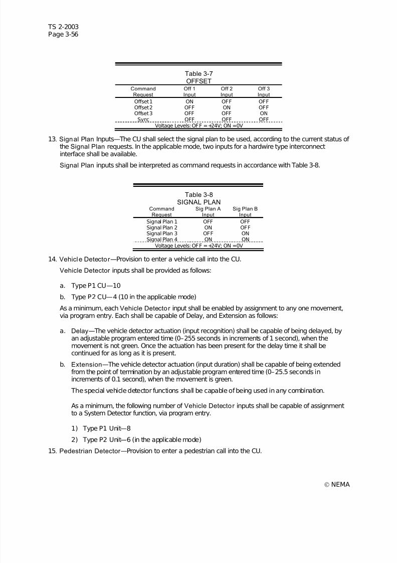
7/30/2019 NEMA TS2-2003- Traffic Controller Assemb
http://slidepdf.com/reader/full/nema-ts2-2003-traffic-controller-assemb 120/246
TS 2-2003Page 3-56
© NEMA
Table 3-7OFFSET
CommandRequest
Off 1Input
Off 2Input
Off 3Input
Offset 1 ON OFF OFFOffset 2 OFF ON OFFOffset 3 OFF OFF ONSync OFF OFF OFF
Voltage Levels: OFF =+24V; ON =0V
13. Signal Plan Inputs—The CU shall select the signal plan to be used, according to the current status of the Signal Plan requests. In the applicable mode, two inputs for a hardwire type interconnectinterface shall be available.
Signal Plan inputs shall be interpreted as command requests in accordance with Table 3-8.
Table 3-8SIGNAL PLAN CommandRequest
Sig Plan AInput
Sig Plan BInput
Signal Plan 1 OFF OFFSignal Plan 2 ON OFFSignal Plan 3 OFF ONSignal Plan 4 ON ON
Voltage Levels: OFF =+24V; ON =0V
14. Vehicle Detector —Provision to enter a vehicle call into the CU.
Vehicle Detector inputs shall be provided as follows:
a. Type P1 CU—10
b. Type P2 CU—4 (10 in the applicable mode)
As a minimum, each Vehicle Detector input shall be enabled by assignment to any one movement,via program entry. Each shall be capable of Delay, and Extension as follows:
a. Delay—The vehicle detector actuation (input recognition) shall be capable of being delayed, byan adjustable program entered time (0–255 seconds in increments of 1 second), when themovement is not green. Once the actuation has been present for the delay time it shall becontinued for as long as it is present.
b. Extension—The vehicle detector actuation (input duration) shall be capable of being extendedfrom the point of termination by an adjustable program entered time (0–25.5 seconds inincrements of 0.1 second), when the movement is green.
The special vehicle detector functions shall be capable of being used in any combination.
As a minimum, the following number of Vehicle Detector inputs shall be capable of assignmentto a System Detector function, via program entry.
1) Type P1 Unit—8
2) Type P2 Unit—6 (in the applicable mode)
15. Pedestrian Detector —Provision to enter a pedestrian call into the CU.
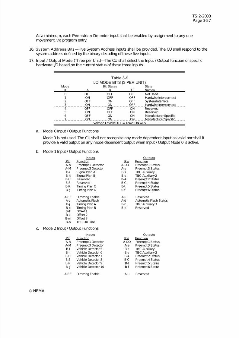
7/30/2019 NEMA TS2-2003- Traffic Controller Assemb
http://slidepdf.com/reader/full/nema-ts2-2003-traffic-controller-assemb 121/246
TS 2-2003Page 3-57
© NEMA
As a minimum, each Pedestrian Detector input shall be enabled by assignment to any onemovement, via program entry.
16. System Address Bits—Five System Address inputs shall be provided. The CU shall respond to thesystem address defined by the binary decoding of these five inputs.
17. Input / Output Mode (Three per Unit)—The CU shall select the Input / Output function of specifichardware I/O based on the current status of these three inputs.
Table 3-9I/O MODE BITS (3 PER UNIT)
Mode Bit States State# A B C Names
0 OFF OFF OFF Not Used1 ON OFF OFF Hardwire Interconnect2 OFF ON OFF System Interface3 ON ON OFF Hardwire Interconnect4 OFF OFF ON Reserved5 ON OFF ON Reserved6 OFF ON ON Manufacturer Specific
7 ON ON ON Manufacturer SpecificVoltage Levels: OFF =+24V; ON =0V
a. Mode 0 Input / Output Functions
Mode 0 is not used. The CU shall not recognize any mode dependent input as valid nor shall itprovide a valid output on any mode dependent output when Input / Output Mode 0 is active.
b. Mode 1 Input / Output Functions
Inputs OutputsPin Function Pin FunctionA-h Preempt 1 Detector A-DD Preempt 1 StatusA-M Preempt 3 Detector A-e Preempt 3 StatusB-i Signal Plan A B-s TBC Auxiliary 1B-h Signal Plan B B-e TBC Auxiliary 2B-U Reserved B-A Preempt 2 StatusB-S Reserved B-C Preempt 4 StatusB-R Timing Plan C B-t Preempt 5 StatusB-g Timing Plan D B-f Preempt 6 Status
A-EE Dimming Enable A-u ReservedA-v Automatic Flash A-d Automatic Flash StatusB-j Timing Plan A B-r TBC Auxiliary 3B-x Timing Plan B B-K ReservedB-T Offset 1B-k Offset 2B-m Offset 3B-n TBC On Line
c. Mode 2 Input / Output Functions
Inputs OutputsPin Function Pin FunctionA-h Preempt 1 Detector A-DD Preempt 1 StatusA-M Preempt 3 Detector A-e Preempt 3 StatusB-I Vehicle Detector 5 B-s TBC Auxiliary 1B-h Vehicle Detector 6 B-e TBC Auxiliary 2B-U Vehicle Detector 7 B-A Preempt 2 StatusB-S Vehicle Detector 8 B-C Preempt 4 StatusB-R Vehicle Detector 9 B-t Preempt 5 StatusB-g Vehicle Detector 10 B-f Preempt 6 Status
A-EE Dimming Enable A-u Reserved
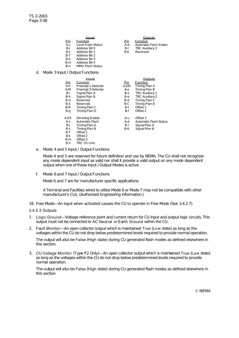
7/30/2019 NEMA TS2-2003- Traffic Controller Assemb
http://slidepdf.com/reader/full/nema-ts2-2003-traffic-controller-assemb 122/246
TS 2-2003Page 3-58
© NEMA
Inputs OutputsPin Function Pin FunctionA-v Local Flash Status A-d Automatic Flash StatusB-j Address Bit 0 B-r TBC Auxiliary 3B-x Address Bit 1 B-K ReservedB-T Address Bit 2
B-k Address Bit 3B-m Address Bit 4B-n MMU Flash Status
d. Mode 3 Input / Output Functions
Inputs OutputsPin Function Pin FunctionA-h Preempt 1 Detector A-DD Timing Plan AA-M Preempt 3 Detector A-e Timing Plan BB-i Signal Plan A B-s TBC Auxiliary 1B-h Signal Plan B B-e TBC Auxiliary 2B-U Reserved B-A Timing Plan CB-S Reserved B-C Timing Plan DB-R Timing Plan C B-t Offset 1B-g Timing Plan D B-f Offset 2
A-EE Dimming Enable A-u Offset 3A-v Automatic Flash A-d Automatic Flash StatusB-j Timing Plan A B-r Signal Plan AB-x Timing Plan B B-K Signal Plan BB-T Offset 1B-k Offset 2B-m Offset 3B-n TBC On Line
e. Mode 4 and 5 Input / Output Functions
Mode 4 and 5 are reserved for future definition and use by NEMA. The CU shall not recognizeany mode dependent input as valid nor shall it provide a valid output on any mode dependentoutput when one of these Input / Output Modes is active.
f. Mode 6 and 7 Input / Output Functions
Mode 6 and 7 are for manufacturer specific applications.
A Terminal and Facilities wired to utilize Mode 6 or Mode 7 may not be compatible with othermanufacturer's CUs. (Authorized Engineering Information.)
18. Free Mode—An input when activated causes the CU to operate in Free Mode (See 3.4.2.7).
3.4.5.3 Outputs
1. Logic Ground—Voltage reference point and current return for CU input and output logic circuits. Thisoutput must not be connected to AC Neut ral orEarth Ground within the CU.
2. Fault Monitor —An open collector output which is maintained True (Low state) as long as thevoltages within the CU do not drop below predetermined levels required to provide normal operation.
The output will also be False (High state) during CU generated flash modes as defined elsewhere inthis section.
3. CU Voltage Monitor (Type P2 Only)—An open collector output which is maintained True (Low state)as long as the voltages within the CU do not drop below predetermined levels required to providenormal operation.
The output will also be False (High state) during CU generated flash modes as defined elsewhere inthis section.
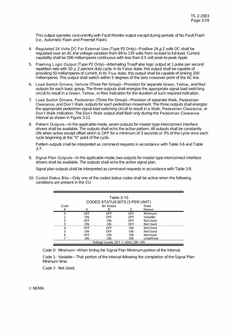
7/30/2019 NEMA TS2-2003- Traffic Controller Assemb
http://slidepdf.com/reader/full/nema-ts2-2003-traffic-controller-assemb 123/246
TS 2-2003Page 3-59
© NEMA
This output operates concurrently with Fault Monitor output except during periods of No Fault Flash(i.e., Automatic Flash and Preempt Flash).
4. Regulated 24 Volts DC For External Use (Type P2 Only)—Positive 24 + 2 volts DC shall beregulated over an AC line voltage variation from 89 to 135 volts from no-load to full-load. Current
capability shall be 500 milliamperes continuous with less than 0.5 volt peak-to-peak ripple.5. Flashing Logic Output (Type P2 Only)—Alternating True/False logic output at 1 pulse per second
repetition rate with 50 + 2 percent duty cycle. In its False state, this output shall be capable of providing 50 milliamperes of current. In its True state, this output shall be capable of sinking 200milliamperes. This output shall switch within 5 degrees of the zero crossover point of the AC line.
6. Load Switch Drivers, Vehicle (Three Per Group)—Provision for separate Green, Yellow, and Red outputs for each basic group. The three outputs shall energize the appropriate signal load switchingcircuit to result in a Green, Yellow, orRed indication for the duration of such required indication.
7. Load Switch Drivers, Pedestrian (Three Per Group)—Provision of separate Walk, PedestrianClearance, and Don’t Walk outputs for each pedestrian movement. The three outputs shall energizethe appropriate pedestrian signal load switching circuit to result in a Walk, Pedestrian Clearance, orDon’t Walk indication. The Don’t Walk output shall flash only during the Pedestrian Clearance
interval as shown in Figure 3-12.
8. Pattern Outputs—In the applicable mode, seven outputs for master type interconnect interfacedrivers shall be available. The outputs shall echo the active pattern. All outputs shall be constantlyON when active except offset which is OFF for a minimum of 3 seconds or 3% of the cycle once eachcycle beginning at the “0” point of the cycle.
Pattern outputs shall be interpreted as command requests in accordance with Table 3-6 and Table3-7.
9. Signal Plan Outputs—In the applicable mode, two outputs for master type interconnect interfacedrivers shall be available. The outputs shall echo the active signal plan.
Signal plan outputs shall be interpreted as command requests in accordance with Table 3-8.
10. Coded Status Bits—Only one of the coded status codes shall be active when the followingconditions are present in the CU:
Table 3-10CODED STATUS BITS (3 PER UNIT)
Code Bit States State# A B C Names
0 OFF OFF OFF Minimum1 ON OFF OFF Variable2 OFF ON OFF Not Used3 ON ON OFF Not Used4 OFF OFF ON Not Used5 ON OFF ON Not Used
6 OFF ON ON Not Used7 ON ON ON Undefined
Voltage Levels: OFF =+24V; ON =0V
Code 0: Minimum—When timing the Signal Plan Minimum portion of the Interval.
Code 1: Variable—That portion of the interval following the completion of the Signal PlanMinimum time.
Code 2: Not Used.

7/30/2019 NEMA TS2-2003- Traffic Controller Assemb
http://slidepdf.com/reader/full/nema-ts2-2003-traffic-controller-assemb 124/246
TS 2-2003Page 3-60
© NEMA
Code 3: Not Used.
Code 4: Not Used.
Code 5: Not Used.
Code 6: Not Used.
Code 7: Undefined.
3.4.6 Priority Of Input Functions
The priority of input functions shall be in the following order:
1. Power-Up
2. External Start
3. Preemption
4. Interval Advance
5. Stop Time
6. Automatic Flash7. Manual Control Enable
8. Force Off
Lower priority inputs shall condition those of higher priority as defined elsewhere in this standard.
Patterns and signal plans are capable of being selected based on program entry, Interconnect Inputs, Time Base Control events, and a System Interface. The pattern and signal plan select priority shall be asfollows:
1. Program Entry
2. System Interface
3. Time Base Control Event
4. Interconnect Inputs
When the Time Base Control On-line input is active, the Time Base Control event priority will be lowerthan Interconnect Inputs. Should the Sync Monitor diagnostic determine the Interconnect Offset to beinvalid, a Time Base Control event may control.
3.4.7 Indications
Indications shall be provided on the display and appropriately identified to facilitate the determination of the operation of the CU. These indications shall consist of the following as a minimum requirement:
The indications shall provide for the simultaneous (i.e., concurrent) presentation, where concurrent statesexists, of the following states/functions:
Current Status
1. Running Pattern, Control Source
2. Running Pattern, Timing Plan plus Offset
3. Correction In Progress
4. System Zero
5. Cycle Counter
6. Interval In Service
7/30/2019 NEMA TS2-2003- Traffic Controller Assemb
http://slidepdf.com/reader/full/nema-ts2-2003-traffic-controller-assemb 125/246
TS 2-2003Page 3-61
© NEMA
7. Interval Counter
8. Presence of vehicle call
9. Presence of pedestrian call
3.5 ACTUATED CONTROL The Standards in 3.5 respond to the need for the functional interchangeability of Solid State Traffic SignalCUs, actuated Type (2 through 8 phase). Interchangeability of equipment manufactured in conformancewith these standards has been promoted by connector plug compatibility.
Interchangeability of equipment can be achieved only when units are configured to produce the samefunctional operation utilizing exactly the same inputs and outputs.
Configurations 'A1' and 'A2' CUs (see 3.2) shall provide functional capability to meet the actuated controlrequirements contained herein.
3.5.1 Definit ions
These definitions define the nomenclature frequently used in this part of the Standard Publication.
3.5.1.1 RingA ring consists of two or more sequentially timed and individually selected conflicting phases so arrangedas to occur in an established order.
3.5.1.2 Barrier (Compatibil ity L ine)
A barrier (compatibility line) is a reference point in the preferred sequence of a multi-ring CU at which allrings are interlocked. Barriers assure there will be no concurrent selection and timing of conflictingphases for traffic movement in different rings. All rings cross the barrier simultaneously to select and timephases on the other side.
3.5.1.3 Multi-Ring Controller Unit
A multi-ring CU contains two or more interlocked rings which are arranged to time in a preferredsequence and to allow concurrent timing of all rings, subject to the restraint in 3.5.1.2. A dual-ring CU is
illustrated in Figure 3-6.
Figure 3-6DUAL RING CONTROLLER UNIT
7/30/2019 NEMA TS2-2003- Traffic Controller Assemb
http://slidepdf.com/reader/full/nema-ts2-2003-traffic-controller-assemb 126/246
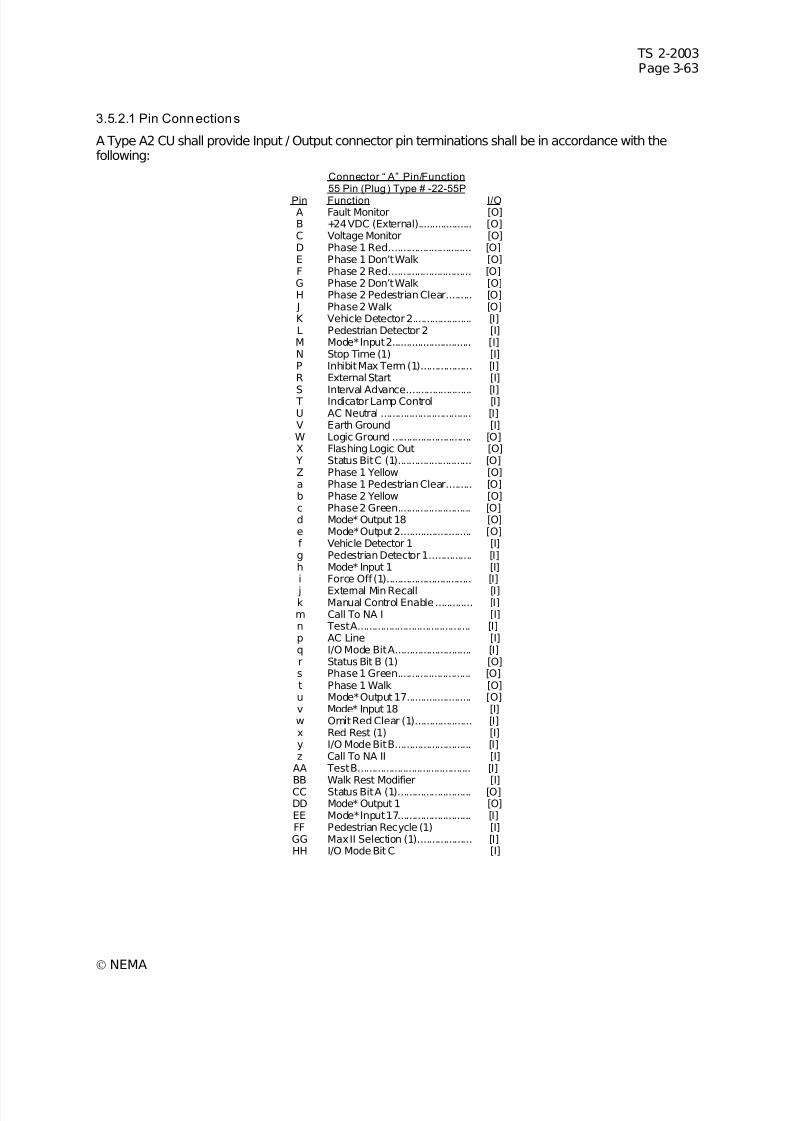
7/30/2019 NEMA TS2-2003- Traffic Controller Assemb
http://slidepdf.com/reader/full/nema-ts2-2003-traffic-controller-assemb 127/246
TS 2-2003Page 3-63
© NEMA
3.5.2.1 Pin Connections
A Type A2 CU shall provide Input / Output connector pin terminations shall be in accordance with thefollowing:
Connector “ A” Pin/Function55 Pin (Plug) Type # -22-55P
Pin Function I/OA Fault Monitor [O]B +24 VDC (External)................... [O]C Voltage Monitor [O]D Phase 1 Red............................. [O]E Phase 1 Don’t Walk [O]F Phase 2 Red............................. [O]G Phase 2 Don’t Walk [O]H Phase 2 Pedestrian Clear......... [O] J Phase 2 Walk [O]K Vehicle Detector 2..................... [I]L Pedestrian Detector 2 [I]M Mode* Input 2............................ [I]N Stop Time (1) [I]P Inhibit Max Term (1).................. [I]R External Start [I]
S Interval Advance....................... [I] T Indicator Lamp Control [I]U AC Neutral ................................ [I]V Earth Ground [I]W Logic Ground ............................ [O]X Flashing Logic Out [O]
Y Status Bit C (1).......................... [O]Z Phase 1 Yellow [O]a Phase 1 Pedestrian Clear......... [O]b Phase 2 Yellow [O]c Phase 2 Green.......................... [O]d Mode* Output 18 [O]e Mode* Output 2......................... [O]f Vehicle Detector 1 [I]g Pedestrian Detector 1............... [I]h Mode* Input 1 [I]i Force Off (1).............................. [I]
j External Min Recall [I]k Manual Control Enable............. [I]m Call To NA I [I]n Test A........................................ [I]p AC Line [I]q I/O Mode Bit A........................... [I]r Status Bit B (1) [O]s Phase 1 Green.......................... [O]t Phase 1 Walk [O]u Mode* Output 17....................... [O]v Mode* Input 18 [I]w Omit Red Clear (1).................... [I]x Red Rest (1) [I]y I/O Mode Bit B........................... [I]z Call To NA II [I]
AA Test B........................................ [I]
BB Walk Rest Modifier [I]CC Status Bit A (1).......................... [O]DD Mode* Output 1 [O]EE Mode* Input 17.......................... [I]FF Pedestrian Recycle (1) [I]GG Max II Selection (1)................... [I]HH I/O Mode Bit C [I]
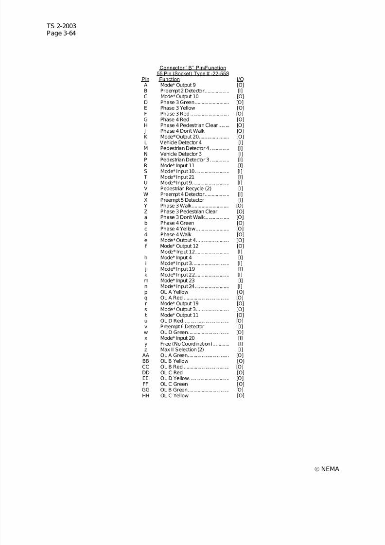
7/30/2019 NEMA TS2-2003- Traffic Controller Assemb
http://slidepdf.com/reader/full/nema-ts2-2003-traffic-controller-assemb 128/246
TS 2-2003Page 3-64
© NEMA
Connector “ B” Pin/Function55 Pin (Socket) Type # -22-55S
Pin Function I/OA Mode* Output 9 [O]B Preempt 2 Detector.................. [I]
C Mode* Output 10 [O]D Phase 3 Green......................... [O]E Phase 3 Yellow [O]F Phase 3 Red............................ [O]G Phase 4 Red [O]H Phase 4 Pedestrian Clear........ [O] J Phase 4 Don’t Walk [O]K Mode* Output 20...................... [O]L Vehicle Detector 4 [I]M Pedestrian Detector 4 .............. [I]N Vehicle Detector 3 [I]P Pedestrian Detector 3 .............. [I]R Mode* Input 11 [I]S Mode* Input 10......................... [I] T Mode* Input 21 [I]U Mode* Input 9........................... [I]
V Pedestrian Recycle (2) [I]W Preempt 4 Detector.................. [I]X Preempt 5 Detector [I]
Y Phase 3 Walk........................... [O]Z Phase 3 Pedestrian Clear [O]a Phase 3 Don’t Walk.................. [O]b Phase 4 Green [O]c Phase 4 Yellow........................ [O]d Phase 4 Walk [O]e Mode* Output 4........................ [O]f Mode* Output 12 [O]
Mode* Input 12......................... [I]h Mode* Input 4 [I]i Mode* Input 3........................... [I]
j Mode* Input 19 [I]k Mode* Input 22......................... [I]m Mode* Input 23 [I]
n Mode* Input 24......................... [I]p OL A Yellow [O]q OL A Red ................................. [O]r Mode* Output 19 [O]s Mode* Output 3........................ [O]t Mode* Output 11 [O]u OL D Red................................. [O]v Preempt 6 Detector [I]w OL D Green.............................. [O]x Mode* Input 20 [I]y Free (No Coordination)............ [I]z Max II Selection (2) [I]
AA OL A Green.............................. [O]BB OL B Yellow [O]CC OL B Red ................................. [O]DD OL C Red [O]EE OL D Yellow............................. [O]FF OL C Green [O]GG OL B Green.............................. [O]HH OL C Yellow [O]
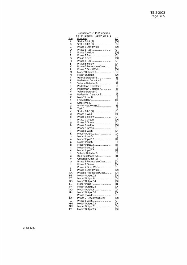
7/30/2019 NEMA TS2-2003- Traffic Controller Assemb
http://slidepdf.com/reader/full/nema-ts2-2003-traffic-controller-assemb 129/246
TS 2-2003Page 3-65
© NEMA
Connector “ C” Pin/Function61 Pin (Socket) Type # -24-61S
Pin Function I/OA Status Bit A (2) [O]B Status Bit B (2).......................... [O]
C Phase 8 Don’t Walk [O]D Phase 8 Red............................. [O]E Phase 7 Yellow [O]F Phase 7 Red............................. [O]G Phase 6 Red [O]H Phase 5 Red............................. [O] J Phase 5 Yellow [O]K Phase 5 Pedestrian Clear......... [O]L Phase 5 Don’t Walk [O]M Mode* Output 13....................... [O]N Mode* Output 5 [O]P Vehicle Detector 5..................... [I]R Pedestrian Detector 5 [I]S Vehicle Detector 6..................... [I] T Pedestrian Detector 6 [I]U Pedestrian Detector 7............... [I]
V Vehicle Detector 7 [I]W Pedestrian Detector 8............... [I]X Mode* Input 8 [I]
Y Force Off (2).............................. [I]Z Stop Time (2) [I]a Inhibit Max Term (2).................. [I]b Test C [I]c Status Bit C (2).......................... [O]d Phase 8 Walk [O]e Phase 8 Yellow......................... [O]f Phase 7 Green [O]g Phase 6 Green.......................... [O]h Phase 6 Yellow [O]i Phase 5 Green.......................... [O]
j Phase 5 Walk [O]k Mode* Output 21....................... [O]m Mode* Input 5 [I]
n Mode* Input 13.......................... [I]p Mode* Input 6 [I]q Mode* Input 14.......................... [I]r Mode* Input 15 [I]s Mode* Input 16.......................... [I]t Vehicle Detector 8 [I]u Red Rest Mode (2).................... [I]v Omit Red Clear (2) [I]w Phase 8 Pedestrian Clear......... [O]x Phase 8 Green [O]y Phase 7 Don’t Walk.................. [O]z Phase 6 Don’t Walk [O]
AA Phase 6 Pedestrian Clear......... [O]BB Mode* Output 22 [O]CC Mode* Output 6......................... [O]DD Mode* Output 14 [O]EE Mode* Input 7............................ [I]FF Mode* Output 24 [O]GG Mode* Output 8......................... [O]HH Mode* Output 16 [O] J J Phase 7 Walk............................ [O]KK Phase 7 Pedestrian Clear [O]LL Phase 6 Walk............................ [O]MM Mode* Output 23 [O]NN Mode* Output 7......................... [O]PP Mode* Output 15 [O]

7/30/2019 NEMA TS2-2003- Traffic Controller Assemb
http://slidepdf.com/reader/full/nema-ts2-2003-traffic-controller-assemb 130/246
TS 2-2003Page 3-66
© NEMA
* Input / Output Functions are dependent on the I/O Mode Bit inputs. See for a definition of the functionassigned to each mode.
3.5.3 Per Phase
The following inputs, outputs, functions, and programming controls shall be provided on a per phase
basis:3.5.3.1 Time Settings
The following functions, with the associated minimum timing ranges and maximum increments, shall beprovided as a minimum when required by the application. For timing accuracy See 2.2.1.
FunctionRange,
SecondsIncrements,
SecondsMin Green 1–255 1Passage Time 0–25.5 0.1Maximum 1 1–255 1Maximum 2 1–255 1
Yellow Change 3–25.5 0.1Red Clearance 0–25.5 0.1Walk 0–255 1
Pedestrian Clearance 0–255 1Added Initial 0–25.5 per Actuation Time to Reduce 1–255 1 Time Before Reduction 1–255 1Minimum Gap 0–25.5 0.1
Zero shall be satisfied by any time between zero and 100 milliseconds.
3.5.3.2 Phase Intervals
1. Green Interval—Actuated Phase
a. Without Volume Density—The Green interval is a variable interval dependent upon vehicleactuations. The Green interval time shall be limited by the Maximum Green time function whichshall commence timing upon registration of a serviceable conflicting call. The Minimum Green time shall not be preempted by a Maximum Green termination.
Three time settings shall be provided for determination of Green timing on an actuated phasewithout volume density.
1) Minimum Green—The first timed portion of the Green interval which may be set inconsideration of the storage of vehicles between the zone of detection for the approachvehicle detector(s) and the stop line.
2) Passage Time (Vehicle Interval, Preset Gap)—The extensible portion of the Green shall bea function of vehicle actuations that occur during the Green interval. The phase shall remainin the extensible portion of the Green interval as long as the passage timer is not timed out.
The timing of this portion of the Green interval shall be reset with each subsequent vehicleactuation and shall not commence to time again until the vehicle actuation is removed fromthe CU. The duration of the Green interval shall be subject to the limit of the Maximum
Green.
3) Maximum Green—This time setting shall determine the maximum length of time this phasemay be held Green in the presence of a serviceable conflicting call. In the absence of aserviceable conflicting call the Maximum Green timer shall be held reset.
b. With Volume Density—In addition to Minimum Green, Passage Time, and Maximum Green timing functions, phases provided with Volume Density operation shall include Variable Init ial timings and Gap Reduction timings. The effect on the Initial timing shall be to increase thetiming in a manner dependent upon the number of vehicle actuations stored on this phase while
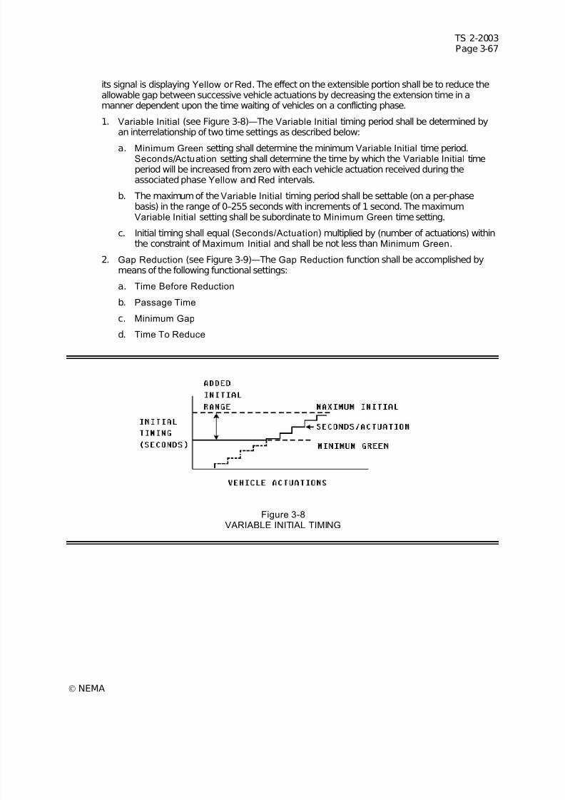
7/30/2019 NEMA TS2-2003- Traffic Controller Assemb
http://slidepdf.com/reader/full/nema-ts2-2003-traffic-controller-assemb 131/246
TS 2-2003Page 3-67
© NEMA
its signal is displaying Yellow or Red. The effect on the extensible portion shall be to reduce theallowable gap between successive vehicle actuations by decreasing the extension time in amanner dependent upon the time waiting of vehicles on a conflicting phase.
1. Variable Initial (see Figure 3-8)—The Variable Initial timing period shall be determined byan interrelationship of two time settings as described below:
a. Minimum Green setting shall determine the minimumVariable Initial time period.Seconds/ Actuation setting shall determine the time by which the Variable Initial timeperiod will be increased from zero with each vehicle actuation received during theassociated phase Yellow and Red intervals.
b. The maximum of the Variable Initial timing period shall be settable (on a per-phasebasis) in the range of 0–255 seconds with increments of 1 second. The maximumVariable Initial setting shall be subordinate to Minimum Green time setting.
c. Initial timing shall equal (Seconds/Actuation) multiplied by (number of actuations) withinthe constraint of Maximum Initial and shall be not less than Minimum Green.
2. Gap Reduction (see Figure 3-9)—The Gap Reduction function shall be accomplished bymeans of the following functional settings:
a. Time Before Reduction
b. Passage Time
c. Minimum Gap
d. Time To Reduce
Figure 3-8VARIABLE INITIAL TIMING
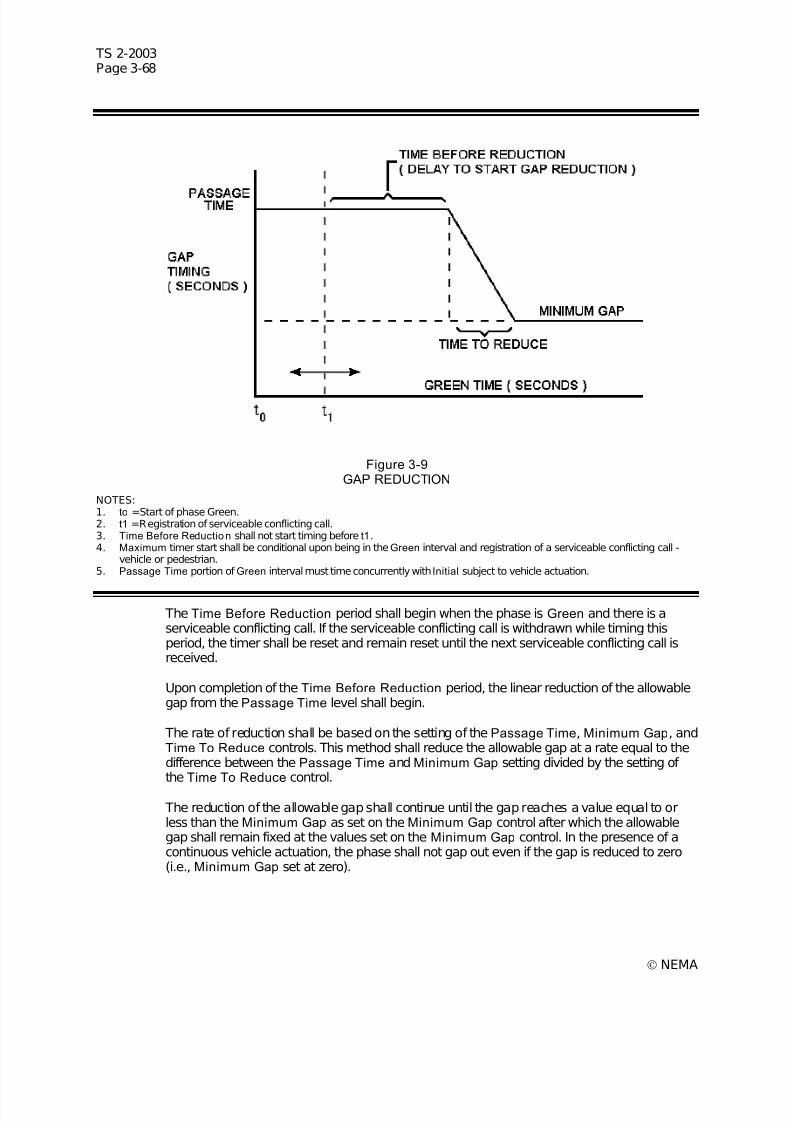
7/30/2019 NEMA TS2-2003- Traffic Controller Assemb
http://slidepdf.com/reader/full/nema-ts2-2003-traffic-controller-assemb 132/246
TS 2-2003Page 3-68
© NEMA
Figure 3-9GAP REDUCTION
NOTES:1. to =Start of phase Green.2. t1 =Registration of serviceable conflicting call.3. Time Before Reduction shall not start timing before t1.4. Maximum timer start shall be conditional upon being in the Green interval and registration of a serviceable conflicting call -
vehicle or pedestrian.5. Passage Time portion of Green interval must time concurrently with Initial subject to vehicle actuation.
The Time Before Reduction period shall begin when the phase is Green and there is aserviceable conflicting call. If the serviceable conflicting call is withdrawn while timing thisperiod, the timer shall be reset and remain reset until the next serviceable conflicting call isreceived.
Upon completion of the Time Before Reduction period, the linear reduction of the allowablegap from the Passage Time level shall begin.
The rate of reduction shall be based on the setting of the Passage Time, Minimum Gap, andTime To Reduce controls. This method shall reduce the allowable gap at a rate equal to thedifference between the Passage Time and Minimum Gap setting divided by the setting of the Time To Reduce control.
The reduction of the allowable gap shall continue until the gap reaches a value equal to orless than the Minimum Gap as set on the Minimum Gap control after which the allowablegap shall remain fixed at the values set on the Minimum Gap control. In the presence of acontinuous vehicle actuation, the phase shall not gap out even if the gap is reduced to zero(i.e., Minimum Gap set at zero).

7/30/2019 NEMA TS2-2003- Traffic Controller Assemb
http://slidepdf.com/reader/full/nema-ts2-2003-traffic-controller-assemb 133/246
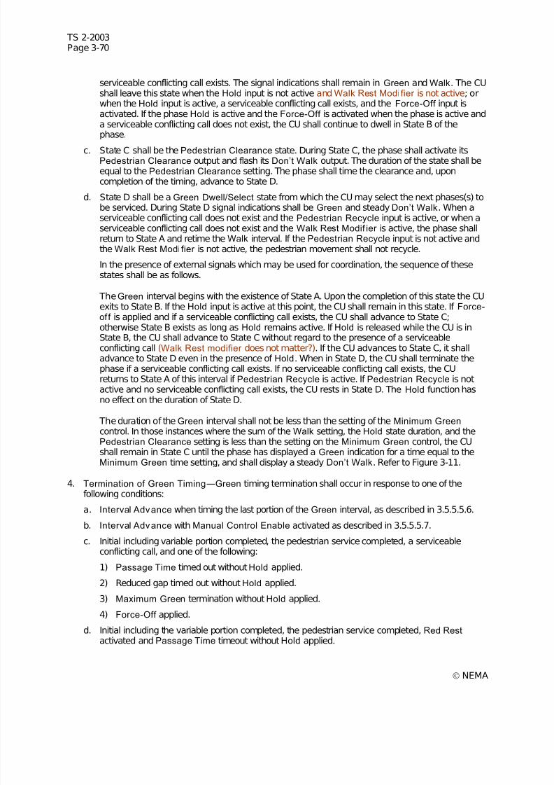
7/30/2019 NEMA TS2-2003- Traffic Controller Assemb
http://slidepdf.com/reader/full/nema-ts2-2003-traffic-controller-assemb 134/246
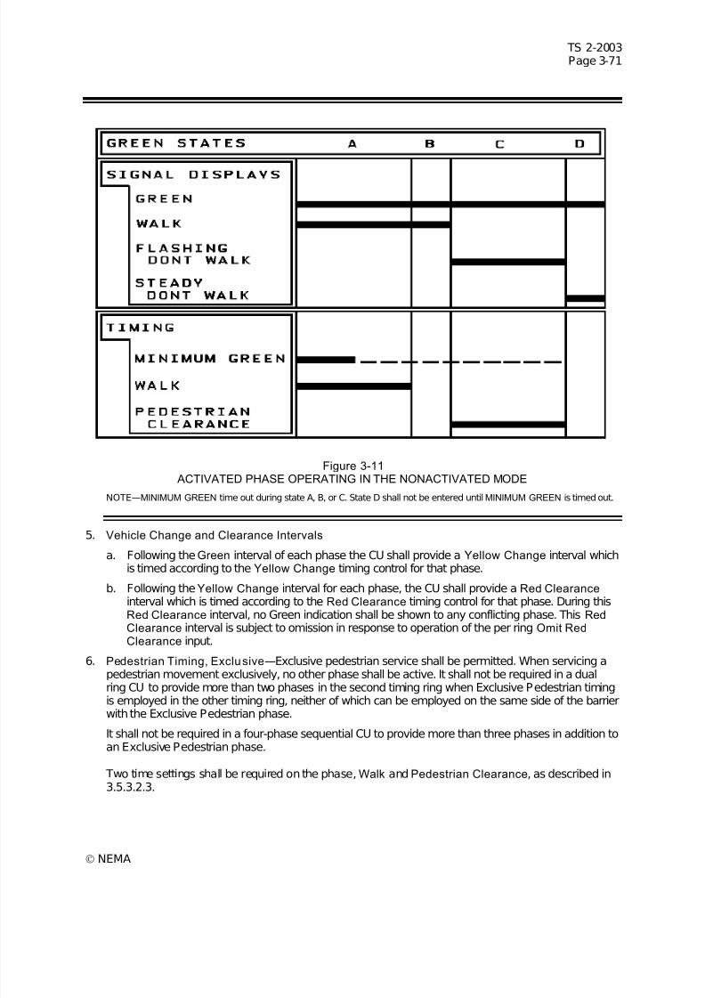
7/30/2019 NEMA TS2-2003- Traffic Controller Assemb
http://slidepdf.com/reader/full/nema-ts2-2003-traffic-controller-assemb 135/246
7/30/2019 NEMA TS2-2003- Traffic Controller Assemb
http://slidepdf.com/reader/full/nema-ts2-2003-traffic-controller-assemb 136/246
TS 2-2003Page 3-72
© NEMA
When a pedestrian call is stored in pedestrian memory, the Exclusive Pedestrian phase shall beserviced with appropriate consideration of its order in the priority of phase sequencing.
The Exclusive Pedestrian phase shall rest with a steady Don’t Walk indication displayed. It shall bepossible to recycle the pedestrian indication in response to succeeding pedestrian calls for service,
subject to absence of serviceable conflicting calls (vehicle or pedestrian) and nonactivation of thePedestrian Omit line.
3.5.3.3 Phase Selection Points
The phase next to be serviced shall be determined at the end of the Green interval of the terminatingphase; except that if the decision cannot be made at the end of the Green interval, it shall not be madeuntil after the end of all vehicle change and clearance intervals.
3.5.3.4 Provision for Storing a Demand
There shall be a provision for storing a call for vehicle service on each vehicle phase when that phase isnot displaying a Green indication. The vehicle memory feature shall be capable of being disabled viaprogram entry. There shall be a provision for storing a call for pedestrian service on phases equipped withpedestrian time setting, when that phase is not displaying a Walk indication.
3.5.3.5 Placement of Maximum Recall
Means shall be provided to place a call on a phase, via program entry, such that the timing of the Green interval for that phase shall be extended to Maximum Green time.
When such a call is placed, the maximum timing shall commence to time as if there were always aserviceable conflicting call, but the phase shall not terminate unless there is an actual serviceableconflicting call.
3.5.3.6 Placement of Minimum Recall
Means shall be provided, via program entry, to place a recurring demand for vehicle service on the phasewhen that phase is not in its Green interval.
3.5.3.7 Placement of Pedestr ian Recall
Means shall be provided to place a recurring pedestrian demand, via program entry, which shall functionin the same manner as an external pedestrian call except that it shall not recycle the pedestrian serviceuntil a conflicting phase is serviced.
3.5.3.8 Placement of Call at Phase Termination
When a phase is terminated with time remaining in the Passage Time, a call shall be left on that phase.Disabling the vehicle call memory shall defeat this feature. If a phase is terminated with no passage timeremaining, no call shall be left on the phase.
3.5.3.9 Condit ional Service
Conditional service shall provide an optional method for phase selection. When timing phasesconcurrently with the next serviceable call on a phase that conflicts with more than one of the phasestiming (about to cross a barrier), if one of the phases is prepared to terminate due to gap out or max time
out, the ring containing the timed out phase shall revert to a preceding vehicle phase if all of the followingconditions apply:
1. A call exists on a preceding actuated vehicle phase. (Non-Actuated Phases shall not be conditionallyreserviced.)
2. The gapped/maxed phase is enabled for conditional service via program entry.
3. There is sufficient time remaining before max time out of the phase(s) not prepared to terminate.
4. The CU is not in coordinated mode.

7/30/2019 NEMA TS2-2003- Traffic Controller Assemb
http://slidepdf.com/reader/full/nema-ts2-2003-traffic-controller-assemb 137/246
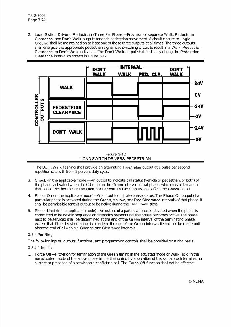
7/30/2019 NEMA TS2-2003- Traffic Controller Assemb
http://slidepdf.com/reader/full/nema-ts2-2003-traffic-controller-assemb 138/246
TS 2-2003Page 3-74
© NEMA
2. Load Switch Drivers, Pedestrian (Three Per Phase)—Provision of separate Walk, PedestrianClearance, and Don’t Walk outputs for each pedestrian movement. A circuit closure to LogicGround shall be maintained on at least one of these three outputs at all times. The three outputsshall energize the appropriate pedestrian signal load switching circuit to result in a Walk, PedestrianClearance, orDon’t Walk indication. The Don’t Walk output shall flash only during the Pedestrian
Clearance interval as shown in Figure 3-12.
Figure 3-12LOAD SWITCH DRIVERS, PEDESTRIAN
The Don’t Walk flashing shall provide an alternating True/False output at 1 pulse per second
repetition rate with 50 + 2 percent duty cycle.
3. Check (In the applicable mode)—An output to indicate call status (vehicle or pedestrian, or both) of the phase, activated when the CU is not in the Green interval of that phase, which has a demand inthat phase. Neither the Phase Omit norPedestrian Omit inputs shall affect the Check output.
4. Phase On (In the applicable mode)—An output to indicate phase status. The Phase On output of aparticular phase is activated during the Green, Yellow, and Red Clearance intervals of that phase. Itshall be permissible for this output to be active during the Red Dwell state.
5. Phase Next (In the applicable mode)—An output of a particular phase activated when the phase iscommitted to be next in sequence and remains present until the phase becomes active. The phasenext to be serviced shall be determined at the end of the Green interval of the terminating phase;except that if the decision cannot be made at the end of the Green interval, it shall not be made until
after the end of all Vehicle Change and Clearance intervals.3.5.4 Per Ring
The following inputs, outputs, functions, and programming controls shall be provided on a ring basis:
3.5.4.1 Inputs
1. Force Off —Provision for termination of the Green timing in the actuated mode or Walk Hold in thenonactuated mode of the active phase in the timing ring by application of this signal, such terminatingsubject to presence of a serviceable conflicting call. The Force Off function shall not be effective
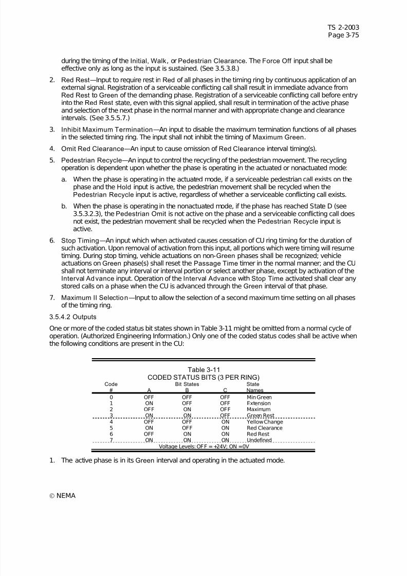
7/30/2019 NEMA TS2-2003- Traffic Controller Assemb
http://slidepdf.com/reader/full/nema-ts2-2003-traffic-controller-assemb 139/246
TS 2-2003Page 3-75
© NEMA
during the timing of the Initial, Walk, or Pedestrian Clearance. The Force Off input shall beeffective only as long as the input is sustained. (See 3.5.3.8.)
2. Red Rest—Input to require rest in Red of all phases in the timing ring by continuous application of anexternal signal. Registration of a serviceable conflicting call shall result in immediate advance fromRed Rest to Green of the demanding phase. Registration of a serviceable conflicting call before entry
into the Red Rest state, even with this signal applied, shall result in termination of the active phaseand selection of the next phase in the normal manner and with appropriate change and clearanceintervals. (See 3.5.5.7.)
3. Inhibit Maximum Termination—An input to disable the maximum termination functions of all phasesin the selected timing ring. The input shall not inhibit the timing of Maximum Green.
4. Omit Red Clearance—An input to cause omission of Red Clearance interval timing(s).
5. Pedestrian Recycle—An input to control the recycling of the pedestrian movement. The recyclingoperation is dependent upon whether the phase is operating in the actuated or nonactuated mode:
a. When the phase is operating in the actuated mode, if a serviceable pedestrian call exists on thephase and the Hold input is active, the pedestrian movement shall be recycled when thePedestrian Recycle input is active, regardless of whether a serviceable conflicting call exists.
b. When the phase is operating in the nonactuated mode, if the phase has reached State D (see3.5.3.2.3), the Pedestrian Omit is not active on the phase and a serviceable conflicting call doesnot exist, the pedestrian movement shall be recycled when the Pedestrian Recycle input isactive.
6. Stop Timing—An input which when activated causes cessation of CU ring timing for the duration of such activation. Upon removal of activation from this input, all portions which were timing will resumetiming. During stop timing, vehicle actuations on non-Green phases shall be recognized; vehicleactuations on Green phase(s) shall reset the Passage Time timer in the normal manner; and the CUshall not terminate any interval or interval portion or select another phase, except by activation of theInterval Advance input. Operation of the Interval Advance with Stop Time activated shall clear anystored calls on a phase when the CU is advanced through the Green interval of that phase.
7. Maximum II Selection—Input to allow the selection of a second maximum time setting on all phasesof the timing ring.
3.5.4.2 Outputs
One or more of the coded status bit states shown in Table 3-11 might be omitted from a normal cycle of operation. (Authorized Engineering Information.) Only one of the coded status codes shall be active whenthe following conditions are present in the CU:
Table 3-11CODED STATUS BITS (3 PER RING)
Code Bit States State# A B C Names
0 OFF OFF OFF Min Green
1 ON OFF OFF Extension2 OFF ON OFF Maximum3 ON ON OFF Green Rest4 OFF OFF ON Yellow Change5 ON OFF ON Red Clearance6 OFF ON ON Red Rest7 ON ON ON Undefined
Voltage Levels: OFF =+24V; ON =0V
1. The active phase is in its Green interval and operating in the actuated mode.

7/30/2019 NEMA TS2-2003- Traffic Controller Assemb
http://slidepdf.com/reader/full/nema-ts2-2003-traffic-controller-assemb 140/246

7/30/2019 NEMA TS2-2003- Traffic Controller Assemb
http://slidepdf.com/reader/full/nema-ts2-2003-traffic-controller-assemb 141/246
TS 2-2003Page 3-77
© NEMA
When timing phases concurrently with the next serviceable call on a phase that conflicts with more thanone of the phases timing (about to cross a barrier), Simultaneous Gap Out, if enabled via program entry,shall insure that all phases which will terminate, must simultaneously reach a point of being committed toterminate before Green timing termination shall begin (i.e., Gap-Out, Max-Out, or Force-Off). When allphases have not yet reached such a point, any gapped out phase shall revert to the extensible portion
and time passage intervals based on vehicle calls.Under the conditions as defined above, Simultaneous Gap Out, if disabled, shall allow a phase to reach apoint of being committed to terminate independently of any other phase and shall not revert to theextensible portion from a gapped out condition.
3.5.5.3 Dual Entry
Dual Entry is a mode of operation (in multi-ring CUs) in which one phase in each ring must be in service,where possible subject to compatibility, at all times.
If a call does not exist in a ring when the CU is committed to cross a barrier, a phase may be selected, viaprogram entry, in that ring to be active.
3.5.5.4 A lternate Sequences
The CU shall provide the capability of fifteen alternates to the standard sequence. The alternates shall bevariations to the sequence based on four groups of two phases (Phase Pair) being serviced in reverseorder.
As a minimum, the sixteen sequences shall provide every combination of lead-lag (phase pair reversal)for an eight phase dual ring CU configuration. For the purpose of this minimum requirement, the AlternateSequences (AS) shall be capable of:
1. AS A—Phase 1 and Phase 2 Reversed
2. AS B—Phase 3 and Phase 4 Reversed
3. AS C—Phase 5 and Phase 6 Reversed
4. AS D—Phase 7 and Phase 8 Reversed
The alternate sequences may be selected by the Alternate Sequence external interface inputs (in theapplicable mode) or the coordinator as a function of the pattern (Timing Plan/Offset) in effect. When theinternal coordinator is running, the external interface inputs for alternate sequences shall be ignored.
Alternate Sequence inputs shall be interpreted as command requests in accordance with Table 3-12.
Table 3-12 ALTERNATE SEQUENCE
CommandRequest
AS AInput
AS BInput
AS CInput
AS DInput
Sequence 00 OFF OFF OFF OFFSequence 01 ON OFF OFF OFFSequence 02 OFF ON OFF OFFSequence 03 ON ON OFF OFF
Sequence 04 OFF OFF ON OFFSequence 05 ON OFF ON OFFSequence 06 OFF ON ON OFFSequence 07 ON ON ON OFFSequence 08 OFF OFF OFF ONSequence 09 ON OFF OFF ONSequence 10 OFF ON OFF ONSequence 11 ON ON OFF ONSequence 12 OFF OFF ON ONSequence 13 ON OFF ON ONSequence 14 OFF ON ON ONSequence 15 ON ON ON ON
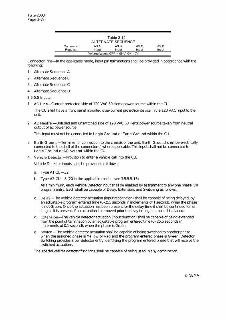
7/30/2019 NEMA TS2-2003- Traffic Controller Assemb
http://slidepdf.com/reader/full/nema-ts2-2003-traffic-controller-assemb 142/246
TS 2-2003Page 3-78
© NEMA
Table 3-12 ALTERNATE SEQUENCE
CommandRequest
AS AInput
AS BInput
AS CInput
AS DInput
Voltage Levels: OFF =+24V; ON =0V
Connector Pins—In the applicable mode, input pin terminations shall be provided in accordance with thefollowing:
1. Alternate Sequence A
2. Alternate Sequence B
3. Alternate Sequence C
4. Alternate Sequence D
3.5.5.5 Inputs
1. AC Line—Current protected side of 120 VAC 60 Hertz power source within the CU.
The CU shall have a front panel mounted over-current protection device in the 120 VAC input to theunit.
2. AC Neut ral—Unfused and unswitched side of 120 VAC 60 Hertz power source taken from neutraloutput of ac power source.
This input must not be connected to Logic Ground orEarth Ground within the CU.
3. Earth Ground—Terminal for connection to the chassis of the unit. Earth Ground shall be electricallyconnected to the shell of the connector(s) where applicable. This input shall not be connected toLogic Ground or AC Neutral within the CU.
4. Vehicle Detector —Provision to enter a vehicle call into the CU.
Vehicle Detector inputs shall be provided as follows:
a. Type A1 CU—32
b. Type A2 CU—8 (20 in the applicable mode—see 3.5.5.5.15)
As a minimum, each Vehicle Detector input shall be enabled by assignment to any one phase, viaprogram entry. Each shall be capable of Delay, Extension, and Switching as follows:
c. Delay—The vehicle detector actuation (input recognition) shall be capable of being delayed, byan adjustable program entered time (0–255 seconds in increments of 1 second), when the phaseis not Green. Once the actuation has been present for the delay time it shall be continued for aslong as it is present. If an actuation is removed prior to delay timing out, no call is placed.
d. Extension—The vehicle detector actuation (input duration) shall be capable of being extendedfrom the point of termination by an adjustable program entered time (0–25.5 seconds inincrements of 0.1 second), when the phase is Green.
e. Switch—The vehicle detector actuation shall be capable of being switched to another phasewhen the assigned phase is Yellow orRed and the program entered phase is Green. DetectorSwitching provides a per detector entry identifying the program entered phase that will receive theswitched actuations.
The special vehicle detector functions shall be capable of being used in any combination.

7/30/2019 NEMA TS2-2003- Traffic Controller Assemb
http://slidepdf.com/reader/full/nema-ts2-2003-traffic-controller-assemb 143/246
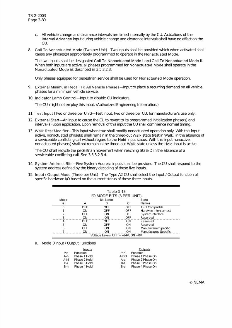
7/30/2019 NEMA TS2-2003- Traffic Controller Assemb
http://slidepdf.com/reader/full/nema-ts2-2003-traffic-controller-assemb 144/246
TS 2-2003Page 3-80
© NEMA
c. All vehicle change and clearance intervals are timed internally by the CU. Actuations of theInterval Advance input during vehicle change and clearance intervals shall have no effect on theCU.
8. Call To Nonactuated Mode (Two per Unit)—Two inputs shall be provided which when activated shallcause any phases(s) appropriately programmed to operate in the Nonactuated Mode.
The two inputs shall be designatedCall To Nonactuated Mode I and Call To Nonactuated Mode II.When both inputs are active, all phases programmed for Nonactuated Mode shall operate in theNonactuated Mode as described in 3.5.3.2.3.
Only phases equipped for pedestrian service shall be used for Nonactuated Mode operation.
9. External Minimum Recall To All Vehicle Phases—Input to place a recurring demand on all vehiclephases for a minimum vehicle service.
10. Indicator Lamp Control—Input to disable CU indicators.
The CU might not employ this input. (Authorized Engineering Information.)
11. Test Input (Two or three per Unit)—Test input, two or three per CU, for manufacturer's use only.12. External Start—An input to cause the CU to revert to its programmed initialization phase(s) and
interval(s) upon application. Upon removal of this input the CU shall commence normal timing.
13. Walk Rest Modif ier —This input when true shall modify nonactuated operation only. With this inputactive, nonactuated phase(s) shall remain in the timed-out Walk state (rest in Walk) in the absence of a serviceable conflicting call without regard to the Hold input status. With this input nonactive,nonactuated phase(s) shall not remain in the timed-out Walk state unless the Hold input is active.
The CU shall recycle the pedestrian movement when reaching State D in the absence of aserviceable conflicting call. See 3.5.3.2.3.d.
14. System Address Bits—Five System Address inputs shall be provided. The CU shall respond to thesystem address defined by the binary decoding of these five inputs.
15. Input / Output Mode (Three per Unit)—The Type A2 CU shall select the Input / Output function of specific hardware I/O based on the current status of these three inputs.
Table 3-13I/O MODE BITS (3 PER UNIT)
Mode Bit States State# A B C Names
0 OFF OFF OFF TS 1 Compatible1 ON OFF OFF Hardwire Interconnect2 OFF ON OFF System Interface3 ON ON OFF Reserved4 OFF OFF ON Reserved5 ON OFF ON Reserved6 OFF ON ON Manufacturer Specific7 ON ON ON Manufactured Specific
Voltage Levels: OFF =+24V; ON =0V
a. Mode 0 Input / Output Functions
Inputs OutputsPin Function Pin FunctionA-h Phase 1 Hold A-DD Phase 1 Phase OnA-M Phase 2 Hold A-e Phase 2 Phase OnB-i Phase 3 Hold B-s Phase 3 Phase OnB-h Phase 4 Hold B-e Phase 4 Phase On
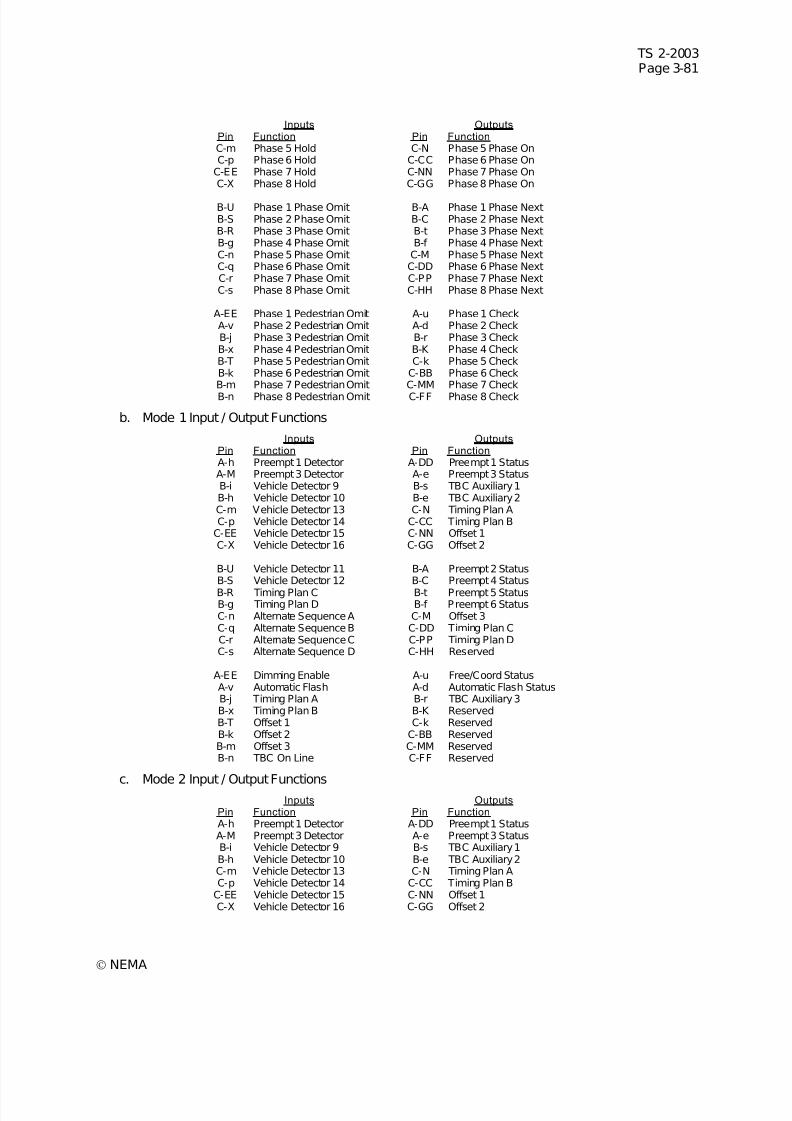
7/30/2019 NEMA TS2-2003- Traffic Controller Assemb
http://slidepdf.com/reader/full/nema-ts2-2003-traffic-controller-assemb 145/246
TS 2-2003Page 3-81
© NEMA
Inputs OutputsPin Function Pin FunctionC-m Phase 5 Hold C-N Phase 5 Phase OnC-p Phase 6 Hold C-CC Phase 6 Phase On
C-EE Phase 7 Hold C-NN Phase 7 Phase OnC-X Phase 8 Hold C-GG Phase 8 Phase On
B-U Phase 1 Phase Omit B-A Phase 1 Phase NextB-S Phase 2 Phase Omit B-C Phase 2 Phase NextB-R Phase 3 Phase Omit B-t Phase 3 Phase NextB-g Phase 4 Phase Omit B-f Phase 4 Phase NextC-n Phase 5 Phase Omit C-M Phase 5 Phase NextC-q Phase 6 Phase Omit C-DD Phase 6 Phase NextC-r Phase 7 Phase Omit C-PP Phase 7 Phase NextC-s Phase 8 Phase Omit C-HH Phase 8 Phase Next
A-EE Phase 1 Pedestrian Omit A-u Phase 1 CheckA-v Phase 2 Pedestrian Omit A-d Phase 2 CheckB-j Phase 3 Pedestrian Omit B-r Phase 3 CheckB-x Phase 4 Pedestrian Omit B-K Phase 4 CheckB-T Phase 5 Pedestrian Omit C-k Phase 5 CheckB-k Phase 6 Pedestrian Omit C-BB Phase 6 CheckB-m Phase 7 Pedestrian Omit C-MM Phase 7 CheckB-n Phase 8 Pedestrian Omit C-FF Phase 8 Check
b. Mode 1 Input / Output Functions
Inputs OutputsPin Function Pin FunctionA-h Preempt 1 Detector A-DD Preempt 1 StatusA-M Preempt 3 Detector A-e Preempt 3 StatusB-i Vehicle Detector 9 B-s TBC Auxiliary 1B-h Vehicle Detector 10 B-e TBC Auxiliary 2C-m Vehicle Detector 13 C-N Timing Plan AC-p Vehicle Detector 14 C-CC Timing Plan B
C-EE Vehicle Detector 15 C-NN Offset 1C-X Vehicle Detector 16 C-GG Offset 2
B-U Vehicle Detector 11 B-A Preempt 2 StatusB-S Vehicle Detector 12 B-C Preempt 4 Status
B-R Timing Plan C B-t Preempt 5 StatusB-g Timing Plan D B-f Preempt 6 StatusC-n Alternate Sequence A C-M Offset 3C-q Alternate Sequence B C-DD Timing Plan CC-r Alternate Sequence C C-PP Timing Plan DC-s Alternate Sequence D C-HH Reserved
A-EE Dimming Enable A-u Free/Coord StatusA-v Automatic Flash A-d Automatic Flash StatusB-j Timing Plan A B-r TBC Auxiliary 3B-x Timing Plan B B-K ReservedB-T Offset 1 C-k ReservedB-k Offset 2 C-BB ReservedB-m Offset 3 C-MM ReservedB-n TBC On Line C-FF Reserved
c. Mode 2 Input / Output FunctionsInputs Outputs
Pin Function Pin FunctionA-h Preempt 1 Detector A-DD Preempt 1 StatusA-M Preempt 3 Detector A-e Preempt 3 StatusB-i Vehicle Detector 9 B-s TBC Auxiliary 1B-h Vehicle Detector 10 B-e TBC Auxiliary 2C-m Vehicle Detector 13 C-N Timing Plan AC-p Vehicle Detector 14 C-CC Timing Plan B
C-EE Vehicle Detector 15 C-NN Offset 1C-X Vehicle Detector 16 C-GG Offset 2
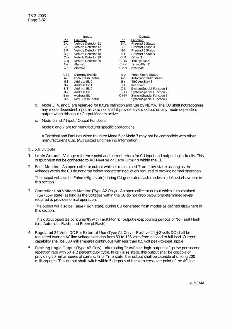
7/30/2019 NEMA TS2-2003- Traffic Controller Assemb
http://slidepdf.com/reader/full/nema-ts2-2003-traffic-controller-assemb 146/246

7/30/2019 NEMA TS2-2003- Traffic Controller Assemb
http://slidepdf.com/reader/full/nema-ts2-2003-traffic-controller-assemb 147/246
TS 2-2003Page 3-83
© NEMA
6. Load Switch Drivers, Vehicle Overlap (Three per Overlap)—Provision of separate Green, Yellow,and Red outputs for each overlap when determined internal to the CU, four overlaps maximum. Acircuit closure to Logic Ground shall be maintained at one of these three outputs at all times. Thethree outputs shall energize the appropriate overlap signal load switching circuit to result in a Green,Yellow, orRed indication for the duration of such required indication.
3.5.5.7 Red Revert
A provision within the CU whereby an adjustable (2–6 seconds)* minimum Red indication will be timedfollowing the Yellow Change interval and prior to the next display of Green on the same phase.
* Not less than 2 seconds and in increments not greater than 1 second.
3.5.6 Priority o f Input Functions
The priority of input functions shall be in the following order:
1. Power-Up
2. External Start
3. Preemption
4. Phase Omit
5. Pedestrian Omit
6. Interval Advance
7. Stop Time
8. Automatic Flash
9. Manual Control Enable
10. Ring Force Off
11. Phase Hold
12. Pedestrian Recycle
Lower priority inputs shall condition those of higher priority as defined elsewhere in this standard.
3.5.7 Indications
Indications shall be provided on the display and appropriately identified to facilitate the determination of the operation of the CU. These indications shall consist of the following as a minimum requirement:
The indications shall provide for the simultaneous (i.e., concurrent) presentation, where concurrent statesexists, of the following states/functions:
Phase Information:
1. Phase or phases in service
2. Phase or phases next to be serviced
3. Presence of vehicle call4. Presence of pedestrian call
The above information shall be displayed simultaneously for all phases.
Status of Active Phase in the Ring:
1. Initial
2. Extension
7/30/2019 NEMA TS2-2003- Traffic Controller Assemb
http://slidepdf.com/reader/full/nema-ts2-2003-traffic-controller-assemb 148/246

7/30/2019 NEMA TS2-2003- Traffic Controller Assemb
http://slidepdf.com/reader/full/nema-ts2-2003-traffic-controller-assemb 149/246
TS 2-2003Page 3-85
© NEMA
3.6.2.1.1 Cycles
The coordinator shall be capable of providing a minimum of 1 cycle length for each timing plan. Eachcycle shall be adjustable over a range of 30 to 255 seconds in 1-second increments.
3.6.2.1.2 Splits
A minimum of 1 set of splits shall be provided for each timing plan. Each split shall provide an adjustabletime for each phase, each adjustable from 0 to 100 percent in 1-percent increments or from 0 to 255seconds in 1-second increments.
3.6.2.2 Offset
Coordination shall include a minimum of three offsets per timing plan, each adjustable from 0 to 100percent in 1 percent increments or from 0 to 254 seconds in 1 second increments.
The values shall determine the latest time that the starting point of the coordinated phase Green, localtime zero, shall lag the Synchronization pulse, system time zero.
The Coordinator shall recognize when the sync reference and local offset in control indicate local zero isnot correct. When establishing its offset based on the sync pulse, the coordinator shall reference only theleading edge, regardless of the width of the sync pulse. The pulse width shall be a minimum of 3 seconds
or 3 percent of the cycle.
It shall be possible to enact Free Mode as a function of the Timing Plan plus Offset in effect. This shall beaccomplished via program entry.
3.6.2.3 Sync Monitor
The coordinator shall monitor the Offset command requests for validity of the imposed sync reference.
The coordinator shall cause the CU to revert to Free mode when:
1. No sync pulse is received for three consecutive cycles.
2. No offset line is active for 15 seconds.
3. More than one offset line is active for 15 seconds.
During Sync Monitor Free mode, the Offset command requests shall continue to be monitored and shouldthe command request return to valid operation, the coordinator shall implement the pattern commanded.
The Sync Monitor Free mode may be replaced by a TBC event. See the On-Line definition in the TimeBase section.
3.6.2.4 Manual Contro l
The coordinator shall be capable of being set to manually operate in any pattern (Timing Plan plus Offset)via program entry. A manual selection of pattern overrides all other pattern interface commands.
3.6.2.5 Free Mode
The coordinator shall be capable of Free mode of operation. During this mode all coordinator control of the CU operation shall be removed.
The coordinator shall be capable of being set to the Free mode defined under Sync Monitor and viaprogram entry.
The coordinator shall recognize input requests that conflict with the internal coordination operation andautomatically revert to Free mode while the inputs are active. The inputs that conflict with internalcoordination are:
1. Manual Control Enable
2. Any Stop Time
3. Automatic Flash
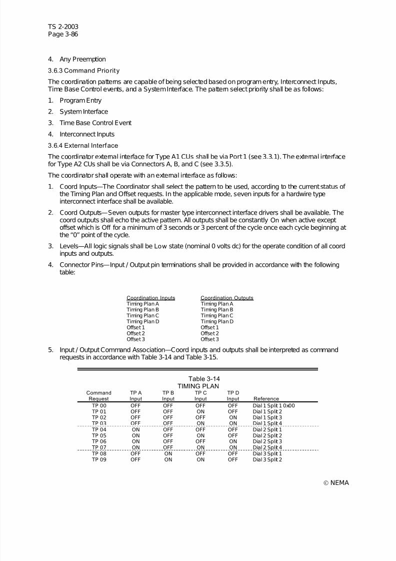
7/30/2019 NEMA TS2-2003- Traffic Controller Assemb
http://slidepdf.com/reader/full/nema-ts2-2003-traffic-controller-assemb 150/246
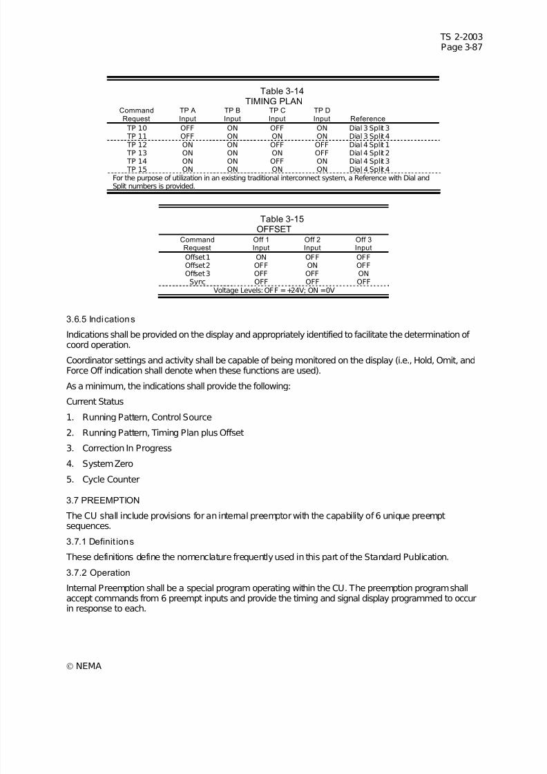
7/30/2019 NEMA TS2-2003- Traffic Controller Assemb
http://slidepdf.com/reader/full/nema-ts2-2003-traffic-controller-assemb 151/246
TS 2-2003Page 3-87
© NEMA
Table 3-14TIMING PLAN
CommandRequest
TP AInput
TP BInput
TP CInput
TP DInput Reference
TP 10 OFF ON OFF ON Dial 3 Split 3
TP 11 OFF ON ON ON Dial 3 Split 4 TP 12 ON ON OFF OFF Dial 4 Split 1 TP 13 ON ON ON OFF Dial 4 Split 2 TP 14 ON ON OFF ON Dial 4 Split 3 TP 15 ON ON ON ON Dial 4 Split 4
For the purpose of utilization in an existing traditional interconnect system, a Reference with Dial andSplit numbers is provided.
Table 3-15OFFSET
CommandRequest
Off 1Input
Off 2Input
Off 3Input
Offset 1 ON OFF OFFOffset 2 OFF ON OFFOffset 3 OFF OFF ONSync OFF OFF OFF
Voltage Levels: OFF =+24V; ON =0V
3.6.5 Indications
Indications shall be provided on the display and appropriately identified to facilitate the determination of coord operation.
Coordinator settings and activity shall be capable of being monitored on the display (i.e., Hold, Omit, andForce Off indication shall denote when these functions are used).
As a minimum, the indications shall provide the following:
Current Status
1. Running Pattern, Control Source
2. Running Pattern, Timing Plan plus Offset
3. Correction In Progress
4. System Zero
5. Cycle Counter
3.7 PREEMPTION
The CU shall include provisions for an internal preemptor with the capability of 6 unique preemptsequences.
3.7.1 Definit ions
These definitions define the nomenclature frequently used in this part of the Standard Publication.
3.7.2 Operation
Internal Preemption shall be a special program operating within the CU. The preemption program shallaccept commands from 6 preempt inputs and provide the timing and signal display programmed to occurin response to each.

7/30/2019 NEMA TS2-2003- Traffic Controller Assemb
http://slidepdf.com/reader/full/nema-ts2-2003-traffic-controller-assemb 152/246
TS 2-2003Page 3-88
© NEMA
Preemption controls shall be internally applied. Internally applied preempt controls shall have priority asdefined in 3.5.6.
The preemption program shall recognize the current signal display at the time of preempt and shallprovide transition timing and signal display to a programmed preempt condition. Once the preempt hasbeen satisfied, the preemption program shall provide an exit transition timing and signal display to a
programmed (one for each of the six preempt inputs) return-to-normal condition.
3.7.2.1 Input Priori ty
The Preemption program shall provide for setting priorities of the preemption inputs with respect one tothe other and to other inputs. The priorities shall be as follows:
1. Preempt 1 shall normally have priority over Preempt 2. If Preempt 1 becomes active while thePreemption program is in the Preempt 2 routine, the CU shall immediately terminate the Preempt 2routine and enter the Preempt 1 routine. When Preempt 2 has been terminated by Preempt 1, controlshall not return to Preempt 2 at the end of Preempt 1 except when Preempt 2 demand is still presentat the end of Preempt 1.
The priority of Preempt 1 over Preempt 2 shall be capable of being canceled via program entry. If thepriority has been canceled and the Preempt 1 becomes active while the preemption program is in the
Preempt 2 routine, the Preempt 2 routine shall complete normally. After Preempt 2 is complete, theCU shall enter the Preempt 1 routine only if the Preempt 1 demand is still present.
When Preempt 2 becomes active while the preemption program is in the Preempt 1 routine, thePreempt 1 routine shall complete normally regardless of the priority of Preempt 1 versus Preempt 2.After Preempt 1 is complete, the CU shall enter the Preempt 2 routine only if the Preempt 2 demandis still present. Whenever both inputs become active at the same time, Preempt 1 shall occur first.
Preempt 2 shall normally have priority over Preempt 3. The priority of Preempt 2 over Preempt 3 shallbe capable of being canceled via program entry.
Preempt 3, 4, 5, and 6 shall normally have equal status (priority canceled). A priority of Preempt 3over Preempt 4, Preempt 4 over Preempt 5, and Preempt 5 over Preempt 6 shall be capable of being
established via program entry.
Operation capability as described above for Preempt 1 and 2 shall be provided for Preempt 2 and 3, 3and 4, 4 and 5, and 5 and 6.
The default priorities above were established assuming Preempt 1 and Preempt 2 as railroad andPreempt 3 to Preempt 6 as emergency vehicle. (Authorized Engineering Information.)
2. All Preempt routines shall normally have priority over Automatic Flash. If any Preempt becomesactive while the CU is in Automatic Flash, Automatic Flash shall terminate normally and the CU shallenter the Preempt routine.
The priority of Preempt over Automatic Flash shall be capable of being canceled via program entry. If the priority of Preempt over Automatic Flash has been canceled and a Preempt input becomes active
while the CU is in Automatic Flash, the CU shall remain in Automatic Flash until the demand (bothAutomatic Flash and Preempt) is terminated.
3. Start-Up Flash shall always have priority over all Preempt routines. If a Preempt input becomes activeor is active during Start-Up Flash, the CU shall maintain the Start-Up Flash condition for the durationof the both Preempt demand and Start-Up Flash time.
4. External Start shall always have priority over all Preempt routines. If External Start becomes activeduring a Preempt routine, the CU shall revert to Start-Up Flash rather than the Initialization condition.

7/30/2019 NEMA TS2-2003- Traffic Controller Assemb
http://slidepdf.com/reader/full/nema-ts2-2003-traffic-controller-assemb 153/246

7/30/2019 NEMA TS2-2003- Traffic Controller Assemb
http://slidepdf.com/reader/full/nema-ts2-2003-traffic-controller-assemb 154/246
TS 2-2003Page 3-90
© NEMA
3.8.1.1 Coordinated Universal Time
The National Institute of Standards and Technology operates standard frequency and time stations atFort Collins, Colorado. The broadcasts of WWV may be heard via telephone by dialing (303) 499-7111,Boulder, Colorado. (Not a toll-free number.)
3.8.2 Operation The internal Time Base Control shall be a special program operating within the CU. A minimum of 48different Time Base Control events shall be capable of being programmed over a one year time frame.
The Time Base calendar shall provide automatic compensation for leap years.
The Time Base Control shall provide for Daylight Savings Time to be programmed to occur automaticallyas defined by law in most states or not to occur.
The Time Base clock shall be maintained to within + 0.005 % at 20oC (68
oF) and to within + 0.02% over
the specified operating temperature range as compared to Coordinated Universal Time (WWV) standardfor a period of thirty days during periods when AC power is not applied.
The Time Base Control program shall output Timing Plan plus Offset commands to the coordinationprogram. It shall be possible to perform functions not necessarily traffic related within the Time Base
Control program by programming and use of three auxiliary outputs.
The Time Base coordination pattern sync (Cycle Zero) shall be user programmable to be referenced toany hour/minute or the event time.
3.8.3 External Interface
The Time Base Control external interface for Type A1 and P1 CUs shall be via Port 1 (see 3.3.1). Theexternal interface for Type A2 and P2 CUs shall be via Connectors A, B, and C (see 3.3.5).
The Time Base Control shall operate with an external interface as follows:
1. Time Base Inputs—One input for Time Base control shall be available. The Time Base On Line input,when active, shall disable the Time Base pattern outputs to the internal coordination program.
2. Time Base Outputs—Three outputs for Time Base Auxiliary shall be available. The outputs shall be
On when their respective auxiliary is part of the current time base event.3. Output Levels—All logic signals shall be Low state (nominal 0 volts DC) for the operate condition.
4. Connector Pins—Input / Output pin terminations shall be provided in accordance with the followingtable:
Time Base Inputs Time Base Outputs TBC On Line TBC Auxiliary #1
TBC Auxiliary #2 TBC Auxiliary #3
3.8.4 Indications
Indications shall be provided on the display and appropriately identified to facilitate the determination of time base operation.
As a minimum, the indications shall provide the following:
Current Status
1. Date, Time, Day-Of-Week
2. Current Event Pattern
3. Current Event Auxiliary Functions

7/30/2019 NEMA TS2-2003- Traffic Controller Assemb
http://slidepdf.com/reader/full/nema-ts2-2003-traffic-controller-assemb 155/246
TS 2-2003Page 3-91
© NEMA
3.9 MISCELLANEOUS
3.9.1 Flash
3.9.1.1 Start-Up Flash
The CU shall have provisions whereby an adjustable time period/state (Start-Up Flash—0 to 255 secondsin increments of 1 second) shall occur prior to the Initialization routine.
During the Start-Up Flash state, the Fault Monitor and Voltage Monitor outputs shall be inactive.
When power is restored following a defined power interruption, the Start-Up Flash state shall becomeoperational. No input, other than the lack of AC power, shall prevent this state from the completion and/orexit to the Initialization routine except as noted in this standard.
If a Preempt Input is active during Start-Up Flash timing, the CU shall maintain the Start-Up Flash statefor the duration of the Preempt demand and/or Start-Up Flash time.
3.9.1.2 Automatic Flash
The activation of this input shall cause the following operation to occur:
1. Actuated CUs
The CU shall assure the completion of the Minimum Green orWalk plus PED Clearance time on thecurrent phase(s). Thereafter, if necessary, it shall proceed to the vehicle clearance intervals followedby the programmed Entry Phase(s). After the Entry Phase(s) Minimum Green or Walk plus PEDClearance, the CU shall proceed to the vehicle clearance intervals. Upon completion of the vehicleRed Clearance interval, the CU shall initiate flashing operation. The CU shall maintain this conditionas long as the Automatic Flash input is active.
When the input becomes inactive, the CU shall move immediately to the beginning of the phase(s)programmed as the Exit Phase(s), with a Green/Walk display, calls on all phase vehicle andpedestrian, and shall cease flashing operation.
2. Pretimed CUs
The CU shall cycle normally to the programmed Entry Interval. Upon completion of the interval, theCU shall initiate flashing operation. The CU shall maintain this condition as long as the AutomaticFlash input is active.
When the input becomes inactive, the CU shall move immediately to the beginning of theprogrammed Exit Interval, with calls on all actuated vehicle and pedestrian movements, and shallcease flashing operation.
3. Method
The method by which flashing operation is accomplished shall be determined via program entry andshall be either:
a. Voltage Monitor Output inactive, or
b. Load Switch Driver Output Flashing
Load Switch Driver Output Flashing shall provide an alternating True/False logic output at 1 pulse persecond repetition rate with 50 + 2 percent duty cycle. The selection, via program entry, of Yellowflashing, Red flashing, or Dark for each vehicle load switch driver group (G/Y/R) shall be provided. Allpedestrian load switch driver groups (W/PC/D) shall be inactive (DARK) in flash.

7/30/2019 NEMA TS2-2003- Traffic Controller Assemb
http://slidepdf.com/reader/full/nema-ts2-2003-traffic-controller-assemb 156/246

7/30/2019 NEMA TS2-2003- Traffic Controller Assemb
http://slidepdf.com/reader/full/nema-ts2-2003-traffic-controller-assemb 157/246
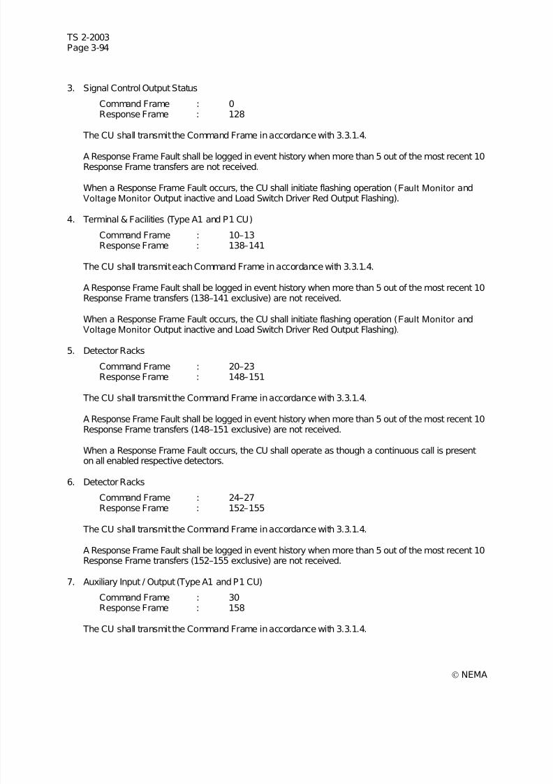
7/30/2019 NEMA TS2-2003- Traffic Controller Assemb
http://slidepdf.com/reader/full/nema-ts2-2003-traffic-controller-assemb 158/246
TS 2-2003Page 3-94
© NEMA
3. Signal Control Output Status
Command Frame : 0Response Frame : 128
The CU shall transmit the Command Frame in accordance with 3.3.1.4.
A Response Frame Fault shall be logged in event history when more than 5 out of the most recent 10Response Frame transfers are not received.
When a Response Frame Fault occurs, the CU shall initiate flashing operation (Fault Monitor andVoltage Monitor Output inactive and Load Switch Driver Red Output Flashing).
4. Terminal & Facilities (Type A1 and P1 CU)
Command Frame : 10–13Response Frame : 138–141
The CU shall transmit each Command Frame in accordance with 3.3.1.4.
A Response Frame Fault shall be logged in event history when more than 5 out of the most recent 10Response Frame transfers (138–141 exclusive) are not received.
When a Response Frame Fault occurs, the CU shall initiate flashing operation (Fault Monitor andVoltage Monitor Output inactive and Load Switch Driver Red Output Flashing).
5. Detector Racks
Command Frame : 20–23Response Frame : 148–151
The CU shall transmit the Command Frame in accordance with 3.3.1.4.
A Response Frame Fault shall be logged in event history when more than 5 out of the most recent 10Response Frame transfers (148–151 exclusive) are not received.
When a Response Frame Fault occurs, the CU shall operate as though a continuous call is presenton all enabled respective detectors.
6. Detector Racks
Command Frame : 24–27Response Frame : 152–155
The CU shall transmit the Command Frame in accordance with 3.3.1.4.
A Response Frame Fault shall be logged in event history when more than 5 out of the most recent 10Response Frame transfers (152–155 exclusive) are not received.
7. Auxiliary Input / Output (Type A1 and P1 CU)
Command Frame : 30Response Frame : 158
The CU shall transmit the Command Frame in accordance with 3.3.1.4.
7/30/2019 NEMA TS2-2003- Traffic Controller Assemb
http://slidepdf.com/reader/full/nema-ts2-2003-traffic-controller-assemb 159/246
TS 2-2003Page 3-95
© NEMA
A Response Frame Fault shall be logged in event history when more than 5 out of the most recent 10Response Frame transfers are not received.
8. Transfer Outputs Frame (Type A1 and P1 CU)
Command Frame : 18
The CU shall transmit the Command Frame in accordance with 3.3.1.4.
A Transfer Outputs Frame Fault shall be logged in event history when the Transfer Outputs Framehas not been transmitted for 500 milleseconds.
When a Transfer Outputs Frame Fault occurs, the CU shall initiate flashing operation (Fault Monitor Output inactive and Load Switch Driver Red Output Flashing).
When the cause of the Frame Fault flash in 1, 2, 3, 4, and 8 above ceases to exist, the CU shall exit tothe beginning of the Start-Up Flash period/state (see 3.9.1.1) except when an address (MMU, T&F BIU 1,etc.) has caused three Frame Fault flash conditions in a calendar day or 24 hour period. The CU shall notexit this Third Time Frame Fault flash state prior to user interaction or AC power being removed and
reapplied.A user interaction shall reset all address Frame Fault counts to zero. AC power interruptions shall notreset any address Frame Fault counts and the next Frame Fault from an address with three or moreFrame Faults in the same calendar day or 24 hour period shall enter the Third Time Frame Fault flashstate.
3.9.3.1.4 Detector Diagnost ics
Each active detector (Vehicle and Pedestrian enabled by assignment) shall be capable of being tested bydiagnostics for conformance to specified parameters. The detector diagnostics shall monitor activity oneach active detector for constant calls, absence of calls, or erratic output.
An active detector is classified as On-Line when the results of the Diagnostic procedures indicate thatdata from the detector is within the allowable range of values.
An active detector is classified as Failed when the results the Diagnostic procedures indicate that datafrom the detector is not within the allowable range of values.
1. No Activity—If an active detector does not exhibit an actuation during a program entered period (00–255 minutes in one minute increments), it is considered a fault by the diagnostics and the detector isclassified as Failed.
2. Maximum Presence—If an active detector exhibits continuous detection for a program enteredperiod (00–255 minutes in one minute increments), it is considered a fault by the diagnostics and thedetector is classified as Failed.
3. Erratic Output—If an active detector exhibits excessive actuations (program entered maximumcounts per minute 00–255 in increments of one), it is considered a fault by the diagnostics and thedetector is classified as Failed.
4. Fault Status—When a Fault status defined in the respective Response Frame 152 to 155 is True foran active detector, it is considered a fault by the diagnostics and the detector is classified as:
a. Failed—Watchdog,
b. Failed—Open Loop,
c. Failed—Shorted Loop,
d. Failed—Excess Change.
Indications shall be provided to facilitate the determination of current diagnostic status of each detector.

7/30/2019 NEMA TS2-2003- Traffic Controller Assemb
http://slidepdf.com/reader/full/nema-ts2-2003-traffic-controller-assemb 160/246

7/30/2019 NEMA TS2-2003- Traffic Controller Assemb
http://slidepdf.com/reader/full/nema-ts2-2003-traffic-controller-assemb 161/246
TS 2-2003Page 3-97
© NEMA
g. Programmed Flash Is Not Active
Two Cycles—When running coordinated, two times the pattern cycle length. When running non-coordinated, two times the longest path between barriers (Maximum Green, Yellow, and Red timessum).
5. MMU Flash—Should the CU MMU Flash input remain active for a period of time exceeding the Start-Up Flash time, the Status is logged as a MMU Flash. If subsequent to a MMU Flash logging the MMUFlash input is removed, the Status shall be logged as On-Line if no other failure is present.
6. Local Flash—Should the CU Local Flash input become active, MMU Flash input is not active, andFlash is not commanded by the Master, the Status shall be logged as a Local Flash. If subsequent toa Local Flash logging the Local Flash input is removed, the Status shall be logged as On-Line if noother failure is present.
7. Preempt—Should any of the CU Preempt inputs become active, the Status shall be logged as aPreempt #. If subsequent to a Preempt logging the Preempt input is removed, the Status shall belogged as On-Line if no other failure is present.
8. Local Free—Should any of the CU inputs and/or programming cause it to not respond to coordination
control, the Status shall be logged as Local Free. If subsequent to a Local Free logging the CUbecomes able to respond to coordination control, the Status shall be logged as Coord Active if noother failure is present.
9. Power On/Off —Should a power interruption occur, the Status shall be logged as Power Off . Whenpower returns the Status shall be logged as Power On.
10. Low Battery—Should any battery voltage fall below the required level, the Status shall be logged asLow Battery.
11. Response Fault—Should a response fault occur (3.9.3.1.3 Port 1), the Status shall be logged asResponse Fault along with the Response Frame number which caused the fault.
12. Alarm 1 and Alarm 2—Should any of the CU Alarm inputs become active, the Status shall be loggedas an Alarm #.
The Events Report shall have the capacity to store a minimum of 100 alarms. The alarms once loggedshall remain until the report capacity is exceeded at which time the oldest alarm shall be deleted and thenew one shall be added.
3.9.3.2 Operator Initiated Diagnosti cs
The CU shall perform diagnostics enabling operator verification of properly operating inputs, outputs,keypad, and display.
The “operator initiated” diagnostics shall be performed only after an operator request through the CUkeypad. The intersection shall automatically and immediately revert to Flash (Fault Monitor and VoltageMonitor Inactive) during this diagnostic. The diagnostics evaluation shall be displayed on the CU frontpanel display and/or indications on a Controller Test Set as an operator interface.
This diagnostic is not intended for use while the CU is in control of intersection operation. (Authorized
Engineering Information.)3.9.3.2.1 Inputs
The CU shall provide test routines to enable operator verification that input functions are proper. This testshall determine whether the input buffers are operating correctly. The user shall activate each input. Theroutine shall identify each input by an indication on the front panel.
The user shall observe the front panel display and determine correct operation.

7/30/2019 NEMA TS2-2003- Traffic Controller Assemb
http://slidepdf.com/reader/full/nema-ts2-2003-traffic-controller-assemb 162/246
7/30/2019 NEMA TS2-2003- Traffic Controller Assemb
http://slidepdf.com/reader/full/nema-ts2-2003-traffic-controller-assemb 163/246

7/30/2019 NEMA TS2-2003- Traffic Controller Assemb
http://slidepdf.com/reader/full/nema-ts2-2003-traffic-controller-assemb 164/246
TS 2-2003Page 3-100
© NEMA

7/30/2019 NEMA TS2-2003- Traffic Controller Assemb
http://slidepdf.com/reader/full/nema-ts2-2003-traffic-controller-assemb 165/246
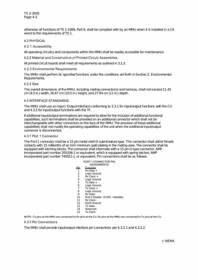
7/30/2019 NEMA TS2-2003- Traffic Controller Assemb
http://slidepdf.com/reader/full/nema-ts2-2003-traffic-controller-assemb 166/246
TS 2-2003Page 4-2
© NEMA
otherwise all functions of TS 1-1989, Part 6, shall be complied with by an MMU when it is installed in a CAwired to the requirements of TS 1.
4.2 PHYSICAL
4.2.1 Accessibility
All operating circuitry and components within the MMU shall be readily accessible for maintenance.
4.2.2 Material and Construction o f Printed Circuit Assemblies
All printed circuit boards shall meet all requirements as outlined in 3.2.3.
4.2.3 Environmental Requirements
The MMU shall perform its specified functions under the conditions set forth in Section 2, EnvironmentalRequirements.
4.2.4 Size
The overall dimensions of the MMU, including mating connector(s) and harness, shall not exceed 11.43cm (4.5 in.) width, 26.67 cm (10.5 in.) height, and 27.94 cm (11 in.) depth.
4.3 INTERFACE STANDARDS
The MMU shall use an Input / Output Interface conforming to 3.3.1 for input/output functions with the CUand 4.3.2 for input/output functions with the TF.
If additional input/output terminations are required to allow for the inclusion of additional functionalcapabilities, such terminations shall be provided on an additional connector which shall not beinterchangeable with other connectors on the face of the MMU. The provision of these additionalcapabilities shall not modify the operating capabilities of the unit when the additional input/outputconnector is disconnected.
4.3.1 Port 1 Connector
The Port 1 connector shall be a 15 pin metal shell D subminiature type. The connector shall utilize femalecontacts with 15 millionths of an inch minimum gold plating in the mating area. The connector shall beequipped with latching blocks. The connector shall intermate with a 15 pin D type connector, AMPIncorporated part number 205206-1 or equivalent, which is equipped with spring latches, AMPIncorporated part number 745012-1, or equivalent. Pin connections shall be as follows:
PORT 1 CONNECTOR PIN ASSIGNMENTS
Pin Function 1 Rx Data +2 Logic Ground3 Rx Clock +4 Logic Ground5 Tx Data +6 Logic Ground7 Tx Clock +8 Logic Ground9 Rx Data-10 Port 1 Disable (0 VDC =disable)11 Rx Clock-12 Earth Ground13 Tx Data-14 Reserved15 Tx Clock-
NOTE—Tx pins at the MMU are connected to Rx pins at the CU. Rx pins at the MMU are connected to Tx pins at the CU.
4.3.2 Pin Connections
The MMU shall provide input/output interface pin connections per 4.3.2.1 and 4.3.2.2.
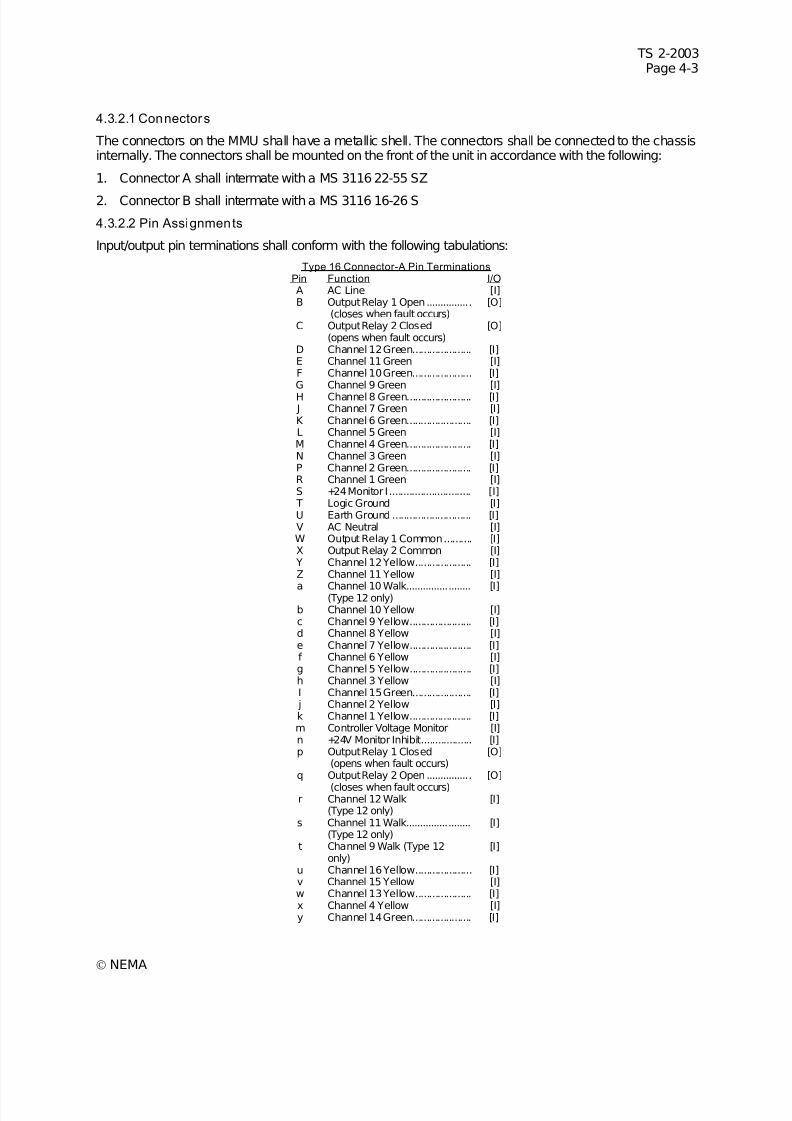
7/30/2019 NEMA TS2-2003- Traffic Controller Assemb
http://slidepdf.com/reader/full/nema-ts2-2003-traffic-controller-assemb 167/246
TS 2-2003Page 4-3
© NEMA
4.3.2.1 Connectors
The connectors on the MMU shall have a metallic shell. The connectors shall be connected to the chassisinternally. The connectors shall be mounted on the front of the unit in accordance with the following:
1. Connector A shall intermate with a MS 3116 22-55 SZ
2. Connector B shall intermate with a MS 3116 16-26 S
4.3.2.2 Pin Assignments
Input/output pin terminations shall conform with the following tabulations:
Type 16 Connector-A Pin TerminationsPin Function I/O A AC Line [I]B Output Relay 1 Open................
(closes when fault occurs)[O]
C Output Relay 2 Closed(opens when fault occurs)
[O]
D Channel 12 Green..................... [I]E Channel 11 Green [I]F Channel 10 Green..................... [I]G Channel 9 Green [I]H Channel 8 Green....................... [I] J Channel 7 Green [I]K Channel 6 Green....................... [I]L Channel 5 Green [I]M Channel 4 Green....................... [I]N Channel 3 Green [I]P Channel 2 Green....................... [I]R Channel 1 Green [I]S +24 Monitor I............................. [I] T Logic Ground [I]U Earth Ground ............................ [I]V AC Neutral [I]W Output Relay 1 Common.......... [I]X Output Relay 2 Common [I]
Y Channel 12 Yellow.................... [I]Z Channel 11 Yellow [I]
a Channel 10 Walk.......................(Type 12 only) [I]
b Channel 10 Yellow [I]c Channel 9 Yellow...................... [I]d Channel 8 Yellow [I]e Channel 7 Yellow...................... [I]f Channel 6 Yellow [I]g Channel 5 Yellow...................... [I]h Channel 3 Yellow [I]I Channel 15 Green..................... [I] j Channel 2 Yellow [I]k Channel 1 Yellow...................... [I]m Controller Voltage Monitor [I]n +24V Monitor Inhibit.................. [I]p Output Relay 1 Closed
(opens when fault occurs)[O]
q Output Relay 2 Open................
(closes when fault occurs)
[O]
r Channel 12 Walk(Type 12 only)
[I]
s Channel 11 Walk.......................(Type 12 only)
[I]
t Channel 9 Walk (Type 12only)
[I]
u Channel 16 Yellow.................... [I]v Channel 15 Yellow [I]w Channel 13 Yellow.................... [I]x Channel 4 Yellow [I]y Channel 14 Green..................... [I]
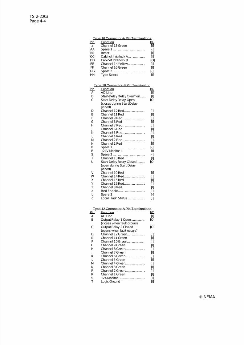
7/30/2019 NEMA TS2-2003- Traffic Controller Assemb
http://slidepdf.com/reader/full/nema-ts2-2003-traffic-controller-assemb 168/246
TS 2-2003Page 4-4
© NEMA
Type 16 Connector-A Pin TerminationsPin Function I/O z Channel 13 Green [I]
AA Spare 1 ..................................... [-]BB Reset [I]CC Cabinet Interlock A.................... [I]
DD Cabinet Interlock B [O]EE Channel 14 Yellow.................... [I]FF Channel 16 Green [I]GG Spare 2 ..................................... [-]HH Type Select [I]
Type 16 Connector-B Pin TerminationPin Function I/O A AC Line [I]B Start-Delay Relay Common...... [I]C Start-Delay Relay Open
(closes during Start Delayperiod)
[O]
D Channel 12 Red........................ [I]E Channel 11 Red [I]F Channel 9 Red.......................... [I]
G Channel 8 Red [I]H Channel 7 Red.......................... [I] J Channel 6 Red [I]K Channel 5 Red.......................... [I]L Channel 4 Red [I]M Channel 2 Red.......................... [I]N Channel 1 Red [I]P Spare 1 ..................................... [-]R +24V Monitor II [I]S Spare 2 ..................................... [-] T Channel 13 Red [I]U Start-Delay Relay Closed .........
(open during Start Delayperiod)
[O]
V Channel 10 Red [I]W Channel 14 Red........................ [I]
X Channel 15 Red [I] Y Channel 16 Red........................ [I]Z Channel 3 Red [I]a Red Enable............................... [I]b Spare 3 [-]c Local Flash Status .................... [I]
Type 12 Connector-A Pin TerminationsPin Function I/O A AC Line [I]B Output Relay 1 Open................
(closes when fault occurs)[O]
C Output Relay 2 Closed(opens when fault occurs)
[O]
D Channel 12 Green..................... [I]E Channel 11 Green [I]
F Channel 10 Green..................... [I]G Channel 9 Green [I]H Channel 8 Green....................... [I] J Channel 7 Green [I]K Channel 6 Green....................... [I]L Channel 5 Green [I]M Channel 4 Green....................... [I]N Channel 3 Green [I]P Channel 2 Green....................... [I]R Channel 1 Green [I]S +24 Monitor I............................. [I] T Logic Ground [I]
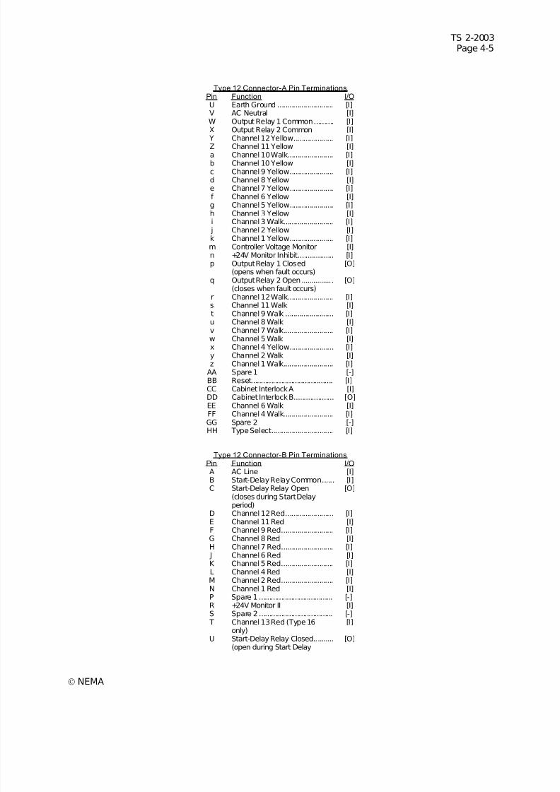
7/30/2019 NEMA TS2-2003- Traffic Controller Assemb
http://slidepdf.com/reader/full/nema-ts2-2003-traffic-controller-assemb 169/246
TS 2-2003Page 4-5
© NEMA
Type 12 Connector-A Pin TerminationsPin Function I/O U Earth Ground ............................ [I]V AC Neutral [I]W Output Relay 1 Common.......... [I]X Output Relay 2 Common [I]
Y Channel 12 Yellow.................... [I]Z Channel 11 Yellow [I]a Channel 10 Walk....................... [I]b Channel 10 Yellow [I]c Channel 9 Yellow...................... [I]d Channel 8 Yellow [I]e Channel 7 Yellow...................... [I]f Channel 6 Yellow [I]g Channel 5 Yellow...................... [I]h Channel 3 Yellow [I]i Channel 3 Walk......................... [I]
j Channel 2 Yellow [I]k Channel 1 Yellow...................... [I]m Controller Voltage Monitor [I]n +24V Monitor Inhibit.................. [I]p Output Relay 1 Closed
(opens when fault occurs)[O]
q Output Relay 2 Open................(closes when fault occurs)
[O]
r Channel 12 Walk....................... [I]s Channel 11 Walk [I]t Channel 9 Walk ........................ [I]u Channel 8 Walk [I]v Channel 7 Walk......................... [I]w Channel 5 Walk [I]x Channel 4 Yellow...................... [I]y Channel 2 Walk [I]z Channel 1 Walk......................... [I]
AA Spare 1 [-]BB Reset......................................... [I]CC Cabinet Interlock A [I]DD Cabinet Interlock B.................... [O]EE Channel 6 Walk [I]
FF Channel 4 Walk......................... [I]GG Spare 2 [-]HH Type Select............................... [I]
Type 12 Connector-B Pin TerminationsPin Function I/O A AC Line [I]B Start-Delay Relay Common...... [I]C Start-Delay Relay Open
(closes during Start Delayperiod)
[O]
D Channel 12 Red........................ [I]E Channel 11 Red [I]F Channel 9 Red.......................... [I]G Channel 8 Red [I]H Channel 7 Red.......................... [I]
J Channel 6 Red [I]K Channel 5 Red.......................... [I]L Channel 4 Red [I]M Channel 2 Red.......................... [I]N Channel 1 Red [I]P Spare 1 ..................................... [-]R +24V Monitor II [I]S Spare 2 ..................................... [-] T Channel 13 Red (Type 16
only)[I]
U Start-Delay Relay Closed..........(open during Start Delay
[O]

7/30/2019 NEMA TS2-2003- Traffic Controller Assemb
http://slidepdf.com/reader/full/nema-ts2-2003-traffic-controller-assemb 170/246
TS 2-2003Page 4-6
© NEMA
Type 12 Connector-B Pin TerminationsPin Function I/O
period)V Channel 10 Red........................ [I]W Channel 14 Red (Type 16
only)[I]
X Channel 15 Red (Type 16only)
[I]
Y Channel 16 Red (Type 16only)
[I]
Z Channel 3 Red.......................... [I]a Red Enable [I]b Spare 3 ..................................... [-]c Local Flash Status [I]
Connector-B pins: S, T, W, X, Y are called out as spare pins in TS 1-1989. (Authorized EngineeringInformation.)
Open contacts of the Output relay are the contacts which are open when the MMU is in the no conflictstate and all voltages are sufficient for proper operation of the CA. (Authorized Engineering Information.)
4.3.3 Inputs
4.3.3.1 AC Line
The over-current protected side of 120 volt AC 60 hertz source. This input shall be employed to generatethe voltages required to operate the monitoring logic.
The MMU shall have a front panel mounted over-current protection device in the 120 volt AC input to theunit.
4.3.3.2 AC Neutral
The unfused and unswitched return side of 120 volt AC 60 hertz power source taken from the neutraloutput of AC power source. This input shall be the reference signal for all field terminal voltage sensinginputs. This input shall not be connected to Logic Ground orEarth Ground within the unit.
4.3.3.3 Earth Ground
The MMU shall have an input terminal providing an independent connection to the chassis of the unit. This input shall not be connected to the Logic Ground or AC Neutral within the unit.
4.3.3.4 Logic Ground
A voltage reference point and current return for the Reset input, Controller Voltage Monitor input, +24VMonitor I input, +24V Monitor II input, Type Select input, +24V Monitor Inhibit input, and Port 1Disable input logic circuits. This termination shall not be connected to either the AC Neutral orEarthGround within the unit.
4.3.3.5 +24V Moni tor Dc Inputs
Two +24 volt DC inputs are monitored to assure proper +24 volt DC levels.
4.3.3.6 Control Inputs
The Reset input, Controller Voltage Monitor input, +24V Monitor Inhibit input, Type Select input ,Local Flash Status input, and Port 1 Disable input are logic level inputs and shall conform to therequirements of 3.3.5.1.1. The MMU shall respond to these inputs as indicated in 4.4.9, 4.4.8, 4.4.7,4.3.3.10, and 4.4.6.
4.3.3.7 Cabinet Interlock
The MMU shall have two terminals internally connected (#22AWG minimum jumper) to indicate thepresence of the unit to the external circuitry. These terminals shall be identified as Cabinet Interlock A and Cabinet Interlock B.

7/30/2019 NEMA TS2-2003- Traffic Controller Assemb
http://slidepdf.com/reader/full/nema-ts2-2003-traffic-controller-assemb 171/246
TS 2-2003Page 4-7
© NEMA
4.3.3.8 Field Terminals
Type 16—Three inputs shall be provided for each channel to permit the monitoring of voltages at theGreen/Walk, Yellow, and Red/Don’t Walk signal field terminals. The unit shall be designed so that itshall not be necessary to terminate unused Green, Yellow, orWalk signal sensing inputs when theimpedance to AC Line of each of these inputs is less than the equivalent of 1500 picofarads (pF) between
the input and AC Line as measured at the input of the unit.
Type 12—Four inputs shall be provided for each channel to permit the monitoring of voltages at theGreen, Yellow, Red, and Walk signal field terminals. The unit shall be designed so that it shall not benecessary to terminate unused Green, Yellow, orWalk signal sensing inputs when the impedance to ACLine of each of these inputs is less than the equivalent of 1500 picofarads (pF) between the input and ACLine as measured at the input of the unit.
A Green, Yellow, orWalk signal input shall be sensed when it exceeds 25 volts RMS AC and a signalinput shall not be sensed when it is less than 15 volts RMS AC. Signals between 15 and 25 volts RMSAC may or may not be sensed. Both positive and negative half wave rectified signals shall be sensed. The RMS measurement shall be made over a minimum period of at least two cycles.
A Red/Don’t Walk signal input shall require the presence of 60 + 10 volts RMS AC at the field terminal to
satisfy the requirements of a Red/Don’t Walk signal indication. Both positive and negative half waverectified signals shall be sensed. The RMS measurement shall be made over a minimum period of atleast two cycles.
A half wave rectified 60 Hz sinusoid of 50 volts peak or more on a Green, Yellow, orWalk input isequivalent to 25 volts RMS AC or more. A half wave rectified 60 Hz sinusoid of 30 volts peak or less on aGreen, Yellow, orWalk input is equivalent to 15 volts RMS AC or less. A half wave rectified 60 Hzsinusoid of 140 volts peak or more on a Red/Don’t Walk input is equivalent to 70 volts RMS AC or more.A half wave rectified 60 Hz sinusoid of 100 volts peak or less on a Red/Don’t Walk input is equivalent to50 volts RMS AC or less. (Authorized Engineering Information.)
When the circuit connected to the sensing input of the unit exhibits high impedance characteristics suchas caused by dimmers or burned out lamps, it may be necessary to place a low impedance deviceexternal to the unit between the unit input and AC Neut ral . See 6.2.4. (Authorized EngineeringInformation.)
All unused Red/Don’ t Walk signal inputs shall be terminated to AC Line. (Authorized EngineeringInformation.)
4.3.3.9 Red Enable
The presence of the proper voltage at this terminal enables the MMU to detect the absence of voltage onall field signal inputs of a channel. The absence of the proper voltage inhibits the detection of the absenceof voltage on all field signal inputs of a channel. This input shall be considered enabled when the inputvoltage exceeds 89 volts RMS AC at the Red Enable input. This function shall not be considered enabledwhen the input voltage is less than 70 volts RMS AC at the Red Enable input. Signals between 70 and 89volts RMS AC may or may not enable the detection of the absence of voltage on all field signal inputs of achannel.
The presence of the proper voltage at this terminal also enables Minimum Yellow Change/Red Clearance
Interval Monitoring (4.4.5). The absence of the proper voltage at this terminal shall inhibit Minimum Yellow/Red Clearance Interval Monitoring.
4.3.3.10 Type Select Input
The MMU shall operate as a Type 16 with sixteen channels when the Type Select input is at logic True (Low) state, otherwise it shall operate as a Type 12 with twelve channels.
Type 16—Each of the sixteen channels consists of three 120 volt AC inputs: Green/Walk; Yellow; andRed/Don’ t Walk.
7/30/2019 NEMA TS2-2003- Traffic Controller Assemb
http://slidepdf.com/reader/full/nema-ts2-2003-traffic-controller-assemb 172/246
TS 2-2003Page 4-8
© NEMA
Type 12—Each of the twelve channels consists of four 120 volt AC inputs: Green; Yellow; Walk; andRed.
All Port 1 communications activity shall be disabled when the MMU is selected to operate as a Type 12.
4.3.3.11 Local Flash Status
The MMU shall transfer the Output Relay contacts to the Conflict state and set the Local Flash Status bitin the Type 129 Frame to 1 when this input is TRUE. At all other times Local Flash Status bit of the Type129 Frame shall be set to 0.
4.3.4 Outputs
4.3.4.1 Output Relay
The Output relay of the MMU shall have two sets of isolated Form C contacts. These relay contacts shallbe capable of switching all loads in the range from 2 milliamperes at 18 volts direct current to 3 amperesat 135 volts RMS AC.
The open circuit of the Output relay shall be the circuits which are open when the unit is in the No Fault state and all voltages are sufficient for proper operation of the CA. The relay coil shall be energized in theNo Fault state.
Prior to the MMU transferring the Output Relay contacts from the Fault state to the No Fault state, aTransition state with a duration of 500 milliseconds shall occur. During the Transition state the OutputRelay contacts shall be the same as the Fault state and the MMU shall set Start-Up Flash Call bit in the Type 129 Frame to 1. At all other times Start-Up Flash Call bit of the Type 129 Frame shall be set to 0.
4.3.4.2 Start-Delay Control
The MMU shall include a means of detecting an MMU Power Failure (4.4.1). Upon restoration of AC Linefollowing an MMU Power Failure, the Start-Delay relay shall maintain continuity between its common andopen contacts for a period of 2.0 + 0.5 seconds. Following this 2.0 second period of time, the Start-Delay relay shall cause continuity to occur between its common and closed contacts.
The Start-Delay relay shall have a Form C relay output contact. These relay contacts shall be capable of switching all loads in the range from 2 milliamperes at 18 volts direct current to 3 amperes at 135 volts
RMS AC. The operation of the Start-Delay relay normally results in initiating a start-up sequence within the CU byinterrupting the AC Line input to the CU.
4.3.5 Display
The minimum indication shall be as follows:
1. Triggering of the Conflict monitoring portion of the unit.
2. Triggering of the Voltage monitoring portion of the unit.
3. Triggering of the Red monitoring portion of the unit.
4. Triggering of the Minimum Yellow Change/Red Clearance monitoring portion of the unit.
5. Timeout failure on Port 1.6. Triggering of the microprocessor or memory monitoring portion of the unit.
7. One per channel which indicates the presence of an active Green, Yellow, orWalk field input on thatchannel during non-fault conditions. The channel indicator display shall latch when the Conflictmonitor portion of the unit triggers. The channel indicator display shall show the channels whichcaused the Red monitoring or Minimum Yellow Change / Red Clearance monitoring portion of the unitto trigger.
8. Local Flash Status input is TRUE.
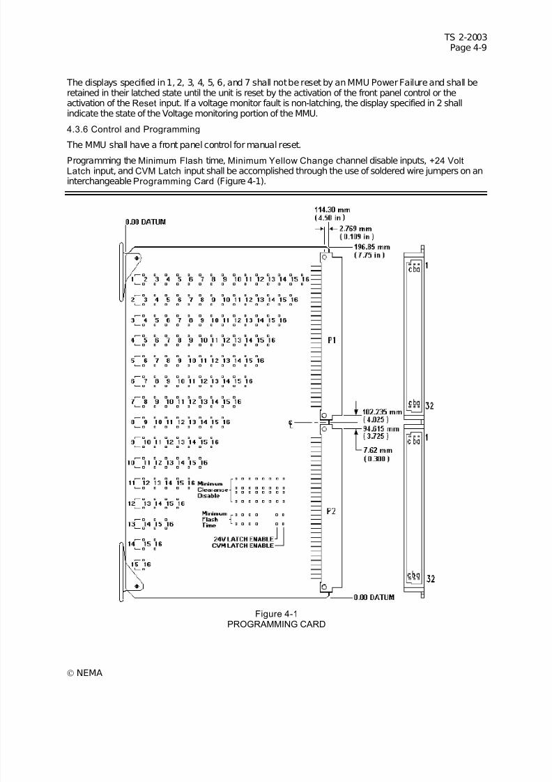
7/30/2019 NEMA TS2-2003- Traffic Controller Assemb
http://slidepdf.com/reader/full/nema-ts2-2003-traffic-controller-assemb 173/246
TS 2-2003Page 4-9
© NEMA
The displays specified in 1, 2, 3, 4, 5, 6, and 7 shall not be reset by an MMU Power Failure and shall beretained in their latched state until the unit is reset by the activation of the front panel control or theactivation of the Reset input. If a voltage monitor fault is non-latching, the display specified in 2 shallindicate the state of the Voltage monitoring portion of the MMU.
4.3.6 Control and Programming
The MMU shall have a front panel control for manual reset.
Programming the Minimum Flash time, Minimum Yellow Change channel disable inputs, +24 VoltLatch input, and CVM Latch input shall be accomplished through the use of soldered wire jumpers on aninterchangeableProgramming Card (Figure 4-1).
Figure 4-1PROGRAMMING CARD

7/30/2019 NEMA TS2-2003- Traffic Controller Assemb
http://slidepdf.com/reader/full/nema-ts2-2003-traffic-controller-assemb 174/246
TS 2-2003Page 4-10
© NEMA
NOTES:1. All dimensions are in metric.2. Tolerances: x.xx =+0.254 mm; x.xxx =+0.127 mm3. Printed Circuit Board thickness: 1.60 mm4. The 94.615 mm & 102.235 mm dimensions are to the center of connector mounting holes.
4.3.6.1 Minimum Flash Programming
The Programming Card shall have four pairs of 1.09 mm (0.043 in.) diameter holes for programming jumpers. One hole of each pair shall be connected to the common pin #32 on rows A and B and C oneach connector. The four jumper hole pairs shall be logically labeled for easy identification of the jumperholes in binary weighted fashion. A soldered wire jumper in a jumper hole pair shall add that designatedinput value to the binary weighted sum plus one.
4.3.6.2 Minimum Yellow Change Channel Disable Programming
The Programming Card shall have 16 pairs of 1.09 mm (0.043 in.) diameter holes for programming jumpers. One hole of each pair shall be connected to the common pin #32 on rows A and B and C oneach connector. The 16 jumper hole pairs shall be logically labeled for easy identification of the channelnumbers. A soldered wire jumper in a jumper hole pair shall disable Minimum Yellow Change monitoringfor that channel.
4.3.6.3 Voltage Monitor Latch Programming
The Programming Card shall have two pairs of 1.09 mm (0.043 in.) diameter holes for programming jumpers. One hole of each pair shall be connected to the common pin #32 on rows A and B and C oneach connector. The two jumper hole pairs shall be logically labeled for easy identification of the +24 VoltLatch input and CVM Latch input. A soldered wire jumper in a jumper hole pair shall cause these faultconditions to be latched.
4.3.7 Compatibility Programming
The MMU is fully programmable and shall require programming action to provide compatibility betweenchannels.
Programming is accomplished through the use of soldered wire jumpers on an interchangeableProgramming Card (Figure 4-1). The interchangeable Programming Card may be used with an MMUoperating in either Type 16 or Type 12 mode.
The Programming Card shall plug into the MMU through a slot in the front panel. The MMU shall providecard guides to ease the insertion of the Programming Card. The Programming Card shall be providedwith card ejectors, Stanford Applied Engineering part number 6100 or equivalent, to ease the removal of the Programming Card.
The edge of the Programming Card shall be flush with the surface of the front panel when it is properlyseated in the program card slot of the MMU.
The Programming Card shall meet the requirements for all printed circuit boards described in TheProgramming Card shall be provided with two male connectors with the following requirements:
1. Each connector having 96 positions in a 3-row contact arrangement with 32 contacts per row on a2.54 mm (0.1 in.) contact grid.
2. Each connector shall conform to DIN 41612, series C.
3. Each connector shall be positioned with pin 1 located at the top.
The Programming Card shall have 120 pairs of 1.09 mm (0.043 in.) diameter holes for programming jumpers. One hole of each pair shall be connected to the common pin #32 on rows A, B, and C on eachconnector. The 120 jumper hole pairs shall be logically labeled for easy identification of the jumper holes
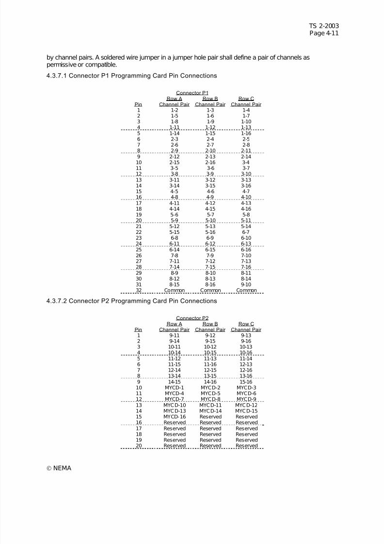
7/30/2019 NEMA TS2-2003- Traffic Controller Assemb
http://slidepdf.com/reader/full/nema-ts2-2003-traffic-controller-assemb 175/246
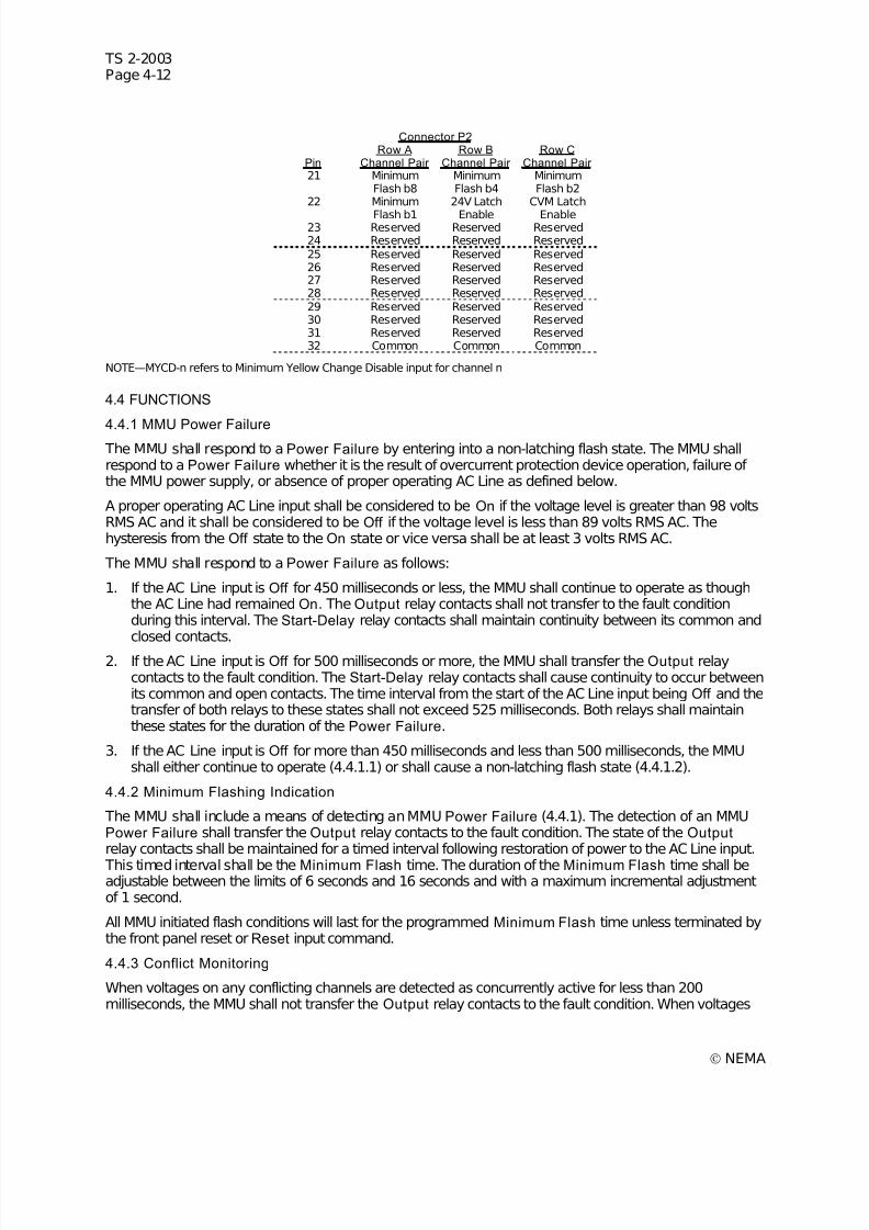
7/30/2019 NEMA TS2-2003- Traffic Controller Assemb
http://slidepdf.com/reader/full/nema-ts2-2003-traffic-controller-assemb 176/246
TS 2-2003Page 4-12
© NEMA
Connector P2
Pin Row A
Channel Pair Row B
Channel Pair Row C
Channel Pair 21 Minimum
Flash b8MinimumFlash b4
MinimumFlash b2
22 Minimum
Flash b1
24V Latch
Enable
CVM Latch
Enable23 Reserved Reserved Reserved24 Reserved Reserved Reserved25 Reserved Reserved Reserved26 Reserved Reserved Reserved27 Reserved Reserved Reserved28 Reserved Reserved Reserved29 Reserved Reserved Reserved30 Reserved Reserved Reserved31 Reserved Reserved Reserved32 Common Common Common
NOTE—MYCD-n refers to Minimum Yellow Change Disable input for channel n
4.4 FUNCTIONS
4.4.1 MMU Power Failure The MMU shall respond to a Power Failure by entering into a non-latching flash state. The MMU shallrespond to a Power Failure whether it is the result of overcurrent protection device operation, failure of the MMU power supply, or absence of proper operating AC Line as defined below.
A proper operating AC Line input shall be considered to be On if the voltage level is greater than 98 voltsRMS AC and it shall be considered to be Off if the voltage level is less than 89 volts RMS AC. Thehysteresis from the Off state to the On state or vice versa shall be at least 3 volts RMS AC.
The MMU shall respond to a Power Failure as follows:
1. If the AC Line input is Off for 450 milliseconds or less, the MMU shall continue to operate as thoughthe AC Line had remained On. The Output relay contacts shall not transfer to the fault conditionduring this interval. The Start-Delay relay contacts shall maintain continuity between its common andclosed contacts.
2. If the AC Line input is Off for 500 milliseconds or more, the MMU shall transfer the Output relaycontacts to the fault condition. The Start-Delay relay contacts shall cause continuity to occur betweenits common and open contacts. The time interval from the start of the AC Line input being Off and thetransfer of both relays to these states shall not exceed 525 milliseconds. Both relays shall maintainthese states for the duration of the Power Failure.
3. If the AC Line input is Off for more than 450 milliseconds and less than 500 milliseconds, the MMUshall either continue to operate (4.4.1.1) or shall cause a non-latching flash state (4.4.1.2).
4.4.2 Minimum Flashing Indication
The MMU shall include a means of detecting an MMU Power Failure (4.4.1). The detection of an MMUPower Failure shall transfer the Output relay contacts to the fault condition. The state of the Output relay contacts shall be maintained for a timed interval following restoration of power to the AC Line input.
This timed interval shall be the Minimum Flash time. The duration of the Minimum Flash time shall beadjustable between the limits of 6 seconds and 16 seconds and with a maximum incremental adjustmentof 1 second.
All MMU initiated flash conditions will last for the programmed Minimum Flash time unless terminated bythe front panel reset or Reset input command.
4.4.3 Conflict Monitoring
When voltages on any conflicting channels are detected as concurrently active for less than 200milliseconds, the MMU shall not transfer the Output relay contacts to the fault condition. When voltages
7/30/2019 NEMA TS2-2003- Traffic Controller Assemb
http://slidepdf.com/reader/full/nema-ts2-2003-traffic-controller-assemb 177/246
TS 2-2003Page 4-13
© NEMA
on any conflicting channels are detected as concurrently active for 450 milliseconds or more, the MMUshall transfer the Output relay contacts to the fault condition. When voltages on any conflicting channelsare detected as concurrently active for more than 200 milliseconds but less than 450 milliseconds, theMMU may or may not transfer the Output relay contacts to the fault condition. The time interval betweenthe beginning of the concurrently conflicting channels and the transfer of the Output relay contacts to the
fault condition shall not exceed 450 milliseconds. A status bit shall be set in the Type 129 Frame (3.3.1.4)and transmitted to the CU through Port 1.
When the MMU transfers the Output relay contacts to the fault condition it shall cause continuity betweenthe open (see 4.3.2.2) and common contacts of the Output relay. These contacts shall remain in this faultcondition until the unit is reset by the activation of a front panel control or the activation of the Reset input.
An MMU Power Failure shall not reset the MMU when it has been triggered by a conflict prior to theMMU Power Failure.
4.4.4 Red Monitoring
The MMU shall be capable of monitoring for the absence of voltage on all of the inputs of a channel.When an absence of all signal voltage to a channel is detected for less than 700 milliseconds, the MMUshall not transfer the Output relay contacts to the fault condition. When an absence of all signal voltage
to a channel is detected for 1000 milliseconds or more, the MMU shall transfer the Output relay contactsto the fault condition. When an absence of all signal voltage to a channel is detected for more than 700milliseconds but less than 1000 milliseconds, the MMU may or may not transfer the Output relay contactsto the fault condition. The time interval between the beginning of the absence of signal voltage on achannel and the transfer of the Output relay contacts to the fault condition shall not exceed 1000milliseconds. A status bit shall be set in the Type 129 Frame (3.3.1.4) and transmitted to the CU throughPort 1.
Red Monitoring shall be disabled when the Red Enable input is not active or if the Load Switch Flash bitis set to 1 in the Type 0 Frame from the CU.
When the MMU transfers the Output relay contacts to the fault condition it shall cause continuity betweenthe open (see 4.3.2.2) and common contacts of the Output relay. These contacts shall remain in this faultcondition until the unit is reset by the activation of a front panel control or the activation of the Reset input.
An MMU Power Failure shall not reset the MMU when it has been triggered by detection of absence of signal voltage on a channel prior to the MMU Power Failure.
4.4.5 Minimum Yellow Change / Red Clearance Interval Monitor ing
4.4.5.1 Yellow Plus Red Interval
The MMU shall verify that the Yellow Change plus Red Clearance interval between the end of an activeGreen signal and the beginning of the next conflicting Green signal is at least 2.7 + 0.1 seconds. Whenthe minimum Yellow Change plus Red Clearance interval is not satisfied, the MMU shall transfer theOutput relay contacts to the fault condition. A status bit shall be set in the Type 129 Frame (3.3.1.4) andtransmitted to the CU through Port 1.
4.4.5.2 Yellow Change Interval
The MMU shall verify that the Yellow Change interval is at least 2.7 + 0.1 seconds. When the minimum
Yellow Change interval is not satisfied, the MMU shall transfer the Output relay contacts to the faultcondition. A programming means shall be provided on the programming card to disable Minimum YellowChange interval monitoring on a per channel basis.
Minimum Yellow Change/Red Clearance Interval (4.4.5.1 and 4.4.5.2) monitoring shall be disabled whenthe Red Enable input is not active.
When the MMU transfers the Output relay contacts to the fault condition it shall cause continuity betweenthe open (see 4.3.2.2) and common contacts of the Output relay. These contacts shall remain in this faultcondition until the unit is reset by the activation of a front panel control or the activation of the Reset input.

7/30/2019 NEMA TS2-2003- Traffic Controller Assemb
http://slidepdf.com/reader/full/nema-ts2-2003-traffic-controller-assemb 178/246
TS 2-2003Page 4-14
© NEMA
An MMU Power Failure shall not reset the MMU when it has been triggered by detection of fault prior tothe MMU Power Failure.
4.4.6 Port 1 Timeout
The MMU shall transfer the Output Relay contacts to the Fault state when a Type 0 Frame (see 3.3.1.4)
has not been received from the CU for 300 milliseconds.When receipt of a Type 0 Frame again occurs, the MMU shall transfer the Output Relay contacts to theNo Fault state except when three Port 1 timeouts have occurred in a calendar day. The MMU shall notexit this Third Timeout state prior to user interaction (front panel control or activation of the Reset input) orAC power being removed and reapplied.
A status bit shall be set to 1 in the Type 129 Frame (3.3.1.4) when the Output Relay Fault state wascaused by a Port 1 Timeout.
A user interaction shall reset Port 1 Timeout counts to zero. AC power interruptions shall not reset thiscount and the next Port 1 Timeout in the same calendar day or 24 hour period shall enter the Third Timeout state.
A Port 1 Timeout failure during the programmedMinimum Flash time or during an MMU Power Failure
shall not cause a latched fault condition. The Port 1 Timeout function shall be disabled if the Port 1Disable input is at a True (Low) state or the MMU is selected to operate as a Type 12 (see 4.3.3.10).
4.4.7 Voltage Monitoring
The MMU shall include the capability of monitoring two +24 volt direct current sources applied to its +24Volt Monitor inputs. Absence of the proper voltage level at either of the inputs shall cause the unit totransfer the Output relay contacts to the fault condition. Restoration of all proper voltage levels shall resetthe Voltage Monitoring portion of the MMU. A +24 volt DC failure during the programmed MinimumFlash time or during an MMU Power Failure shall not cause a fault condition.
A programming means shall be provided on the programming card to cause +24 volt failures to latch inthe fault condition until the unit is reset by the activation of the front panel control or the activation of theReset input. A latched +24 volt DC failure shall not be reset by an MMU Power Failure.
4.4.7.1 Volt Direct Current Supply Monitor
A voltage greater than +22 volts DC applied to both of the +24 Volt Monitor inputs shall be recognized bythe MMU as adequate for proper operation of the CA. A voltage less than +18 volts DC applied to eitherof the +24 Volt Monitor inputs shall be recognized by the MMU as inadequate for proper operation of theCA. Voltages between +22 volts DC and +18 volts DC may or may not be considered inadequate forproper operation of the CA.
When a +24 Volt Monitor input is detected as inadequate for less than 125 milliseconds, the MMU shallnot transfer the Output relay contacts to the fault condition. When a +24 Volt Monitor input is detectedas inadequate for more than 175 milliseconds, the MMU shall transfer the Output relay contacts to thefault condition. When a +24 Volt Monitor input is detected as inadequate for more than 125 millisecondsbut less than 175 milliseconds, the MMU may or may not transfer the Output relay contacts to the faultcondition. The time interval between the beginning of the inadequate voltage level and the transfer of theOutput relay contacts to the fault condition shall not exceed 450 milliseconds. A status bit shall be set in
the Type 129 Frame (3.3.1.4) and transmitted to the CU through Port 1.
If only one +24 volt direct current supply is monitored, the two +24 Volt Monitor inputs should be jumpered and connected to that +24 volt direct current supply. Over the voltage range of 0 to +30 voltsdirect current the maximum current In orOut of the +24 Volt Monitor input terminals shall be less than10 milliamperes. The input impedance of these terminals shall not exceed 11K ohms to Logic Ground. The surge impedance shall not be less than 100 ohms.
4.4.7.2 Volt Monitor Inhibit Input
Application of a TRUE (Low) state to this input shall inhibit the operation of the +24 Volt Monitor.
7/30/2019 NEMA TS2-2003- Traffic Controller Assemb
http://slidepdf.com/reader/full/nema-ts2-2003-traffic-controller-assemb 179/246
TS 2-2003Page 4-15
© NEMA
4.4.8 Controller Voltage/Fault Monitor Input
The MMU shall include an input from the CU (Controller Unit Voltage Monitor (CVM) or Fault Monitor output). When a True (Low) state is absent for less than 125 milliseconds, the MMU shall not transfer theOutput relay contacts to the fault condition. When a True (Low) state is absent for more than 175milliseconds, the MMU shall transfer the Output relay contacts to the fault condition. When a True (Low)
state is absent for more than 125 milliseconds but less than 175 milliseconds, the MMU may or may nottransfer the Output relay contacts to the fault condition. The time interval between the beginning of theabsence of a True (Low) state and the transfer of the Output relay contacts to the fault condition shallnot exceed 450 milliseconds. A status bit shall be set in the Type 129 Frame (3.3.1.4) and transmitted tothe CU through Port 1. A CVM failure during the programmed Minimum Flash time or during an MMUPower Failure shall not cause a fault condition.
A programming means shall be provided on the programming card to cause CVM failures to latch in thefault condition until the unit is reset by the activation of the front panel control or the activation of theReset input. A latched CVM failure shall not be reset by an MMU Power Failure.
4.4.9 Reset
Activation of the front panel control for manual reset or the Reset input shall cause the two Form C
Output relay contacts to transfer to the no-fault condition. The MMU shall remain in the no-fault conditiononly if there are no existing faults and all input voltages are at proper operating levels.
Each activation of the front panel control for manual reset or the Reset input shall cause a one time resetinput to the MMU. A continuously activated front panel manual reset or Reset input shall not prevent theMMU from monitoring any fault conditions and/or transferring the Output relay contacts to the faultcondition. The front panel manual reset or Reset input must be removed and reapplied to activate a newreset input to the MMU.
The only intended purpose for the Reset input is to facilitate bench testing of the MMU. (AuthorizedEngineering Information.)
4.5 DIAGNOSTICS
The MMU shall be provided with a resident series of self-check diagnostic capabilities.
4.5.1 Memory
The MMU shall contain provisions to verify all memory elements on power up. When a fault is detected,the Output relay contacts shall remain in the fault condition. Failure of any of these diagnostics mayresult in a status bit being set in the Type 129 Frame (3.3.1.4) and transmitted to the CU through Port 1.
As a minimum, the following memory diagnostics shall be performed:
1. RAM Diagnostic—This test shall verify that all RAM elements are operating correctly. Patterns shallbe written to RAM. Each Write shall be followed by a Read to verify that it contains the pattern.
2. ROM Diagnostic—This test shall verify that the Operating System ROM(s) contain the properprogram. The routine shall perform a check on each ROM and make a comparison with apreprogrammed value.
3. Non-Volatile Memory Diagnostic—This test shall verify whether the Non-Volatile Memory containsvalid data and that the data has not changed since the last write. The routine shall perform a checkon each Non-Volatile Memory Element and make a comparison with a preprogrammed value.
The MMU shall continue to verify ROM and Non-Volatile Memory during normal operation at a minimumrate of 1024 bytes per second. When a fault is detected, the unit shall transfer the Output relay contactsto the fault condition.

7/30/2019 NEMA TS2-2003- Traffic Controller Assemb
http://slidepdf.com/reader/full/nema-ts2-2003-traffic-controller-assemb 180/246
TS 2-2003Page 4-16
© NEMA
4.5.2 Microprocessor Monitor
The MMU shall monitor the operation of its microprocessor. As a minimum, the monitoring circuit shallreceive signals or logic state transitions at least once every 50 milliseconds from the microprocessor.When the signal or logic state transition is not received for 200 milliseconds, maximum, the monitor circuitshall transfer the Output relay to the fault condition.
7/30/2019 NEMA TS2-2003- Traffic Controller Assemb
http://slidepdf.com/reader/full/nema-ts2-2003-traffic-controller-assemb 181/246
TS 2-2003Page 5-1
© NEMA
SECTION 5TERMINALS AND FACILITIES
These standards define the minimum requirements for Terminals and Facilities (TF) within the cabinet.Specific construction and performance standards are established for the purpose of achieving greaterutility and safety.
These standards define the performance and construction requirements of cabinet terminals and facilitiesthat are considered to be of the attached or nonplug-in type. The emphasis is placed upon electricalrequirements, cabling, supporting terminal facilities, and labeling.
Any tests or procedures referenced in this section of the standards publication are intended to facilitatetype testing of equipment designs and are not intended to be performed on all production units.
5.1 DEFINITIONS
5.1.1 Cabinet
An outdoor enclosure designed for base, pedestal, or pole mounting providing protection, support,ventilation, and security for the enclosed facilities and equipment.
5.1.2 Flash Bus
An AC Line feed supplying flashing power to the flash-transfer device(s) from an output of a flasher.
5.1.3 Earth Ground
An electrical connection between a circuit or piece of equipment and the earth.
5.1.4 Logic Ground
Voltage reference point and current return for DC logic circuits.
5.1.5 Primary Feed
The primary feed is the 120 VAC single phase input to the cabinet from the local power distributionsystem. The primary feed includes the neutral conductor.
5.1.6 Signal Bus
The signal bus is the AC Line feed supplying power to the signal load switches from the output of thesignal bus relay.
5.1.7 Terminal(s)
A terminal is an electrically conductive member serving as a junction to electrically connect two or moreconductors and to also provide a means to individually connect or disconnect conductors. No more thanthree conductors are permitted to be connected to a terminal.
5.2 PHYSICAL
5.2.1 Material
All ferrous metal parts shall be protected against corrosion. All materials shall be moisture and fungusresistant.
5.2.2 Terminal Identi fication
Each electrical terminal within the facilities shall be uniquely identified and shall be referenced by thecabinet wiring diagram.
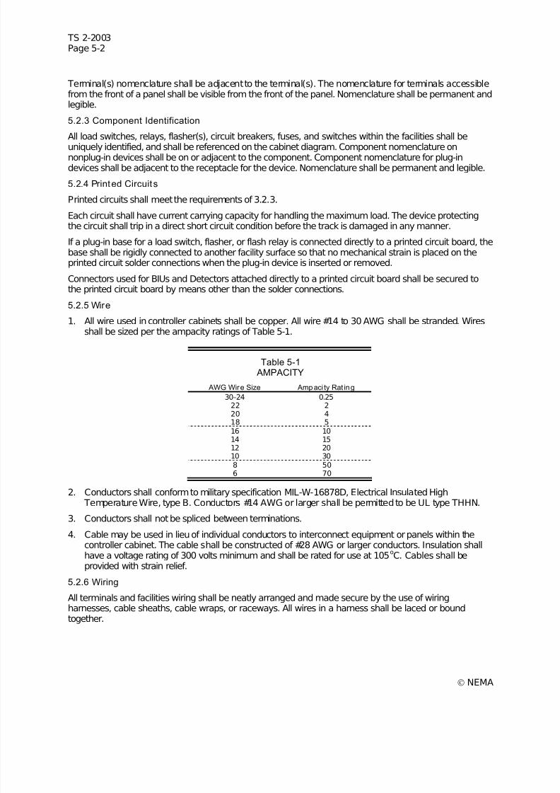
7/30/2019 NEMA TS2-2003- Traffic Controller Assemb
http://slidepdf.com/reader/full/nema-ts2-2003-traffic-controller-assemb 182/246
TS 2-2003Page 5-2
© NEMA
Terminal(s) nomenclature shall be adjacent to the terminal(s). The nomenclature for terminals accessiblefrom the front of a panel shall be visible from the front of the panel. Nomenclature shall be permanent andlegible.
5.2.3 Component Identification
All load switches, relays, flasher(s), circuit breakers, fuses, and switches within the facilities shall beuniquely identified, and shall be referenced on the cabinet diagram. Component nomenclature onnonplug-in devices shall be on or adjacent to the component. Component nomenclature for plug-indevices shall be adjacent to the receptacle for the device. Nomenclature shall be permanent and legible.
5.2.4 Printed Circuit s
Printed circuits shall meet the requirements of 3.2.3.
Each circuit shall have current carrying capacity for handling the maximum load. The device protectingthe circuit shall trip in a direct short circuit condition before the track is damaged in any manner.
If a plug-in base for a load switch, flasher, or flash relay is connected directly to a printed circuit board, thebase shall be rigidly connected to another facility surface so that no mechanical strain is placed on theprinted circuit solder connections when the plug-in device is inserted or removed.
Connectors used for BIUs and Detectors attached directly to a printed circuit board shall be secured tothe printed circuit board by means other than the solder connections.
5.2.5 Wire
1. All wire used in controller cabinets shall be copper. All wire #14 to 30 AWG shall be stranded. Wiresshall be sized per the ampacity ratings of Table 5-1.
Table 5-1 AMPACITY
AWG Wire Size Ampacity Rat ing
30–24 0.2522 2
20 418 516 1014 1512 2010 308 506 70
2. Conductors shall conform to military specification MIL-W-16878D, Electrical Insulated High Temperature Wire, type B. Conductors #14 AWG or larger shall be permitted to be UL type THHN.
3. Conductors shall not be spliced between terminations.
4. Cable may be used in lieu of individual conductors to interconnect equipment or panels within thecontroller cabinet. The cable shall be constructed of #28 AWG or larger conductors. Insulation shall
have a voltage rating of 300 volts minimum and shall be rated for use at 105o
C. Cables shall beprovided with strain relief.
5.2.6 Wiring
All terminals and facilities wiring shall be neatly arranged and made secure by the use of wiringharnesses, cable sheaths, cable wraps, or raceways. All wires in a harness shall be laced or boundtogether.
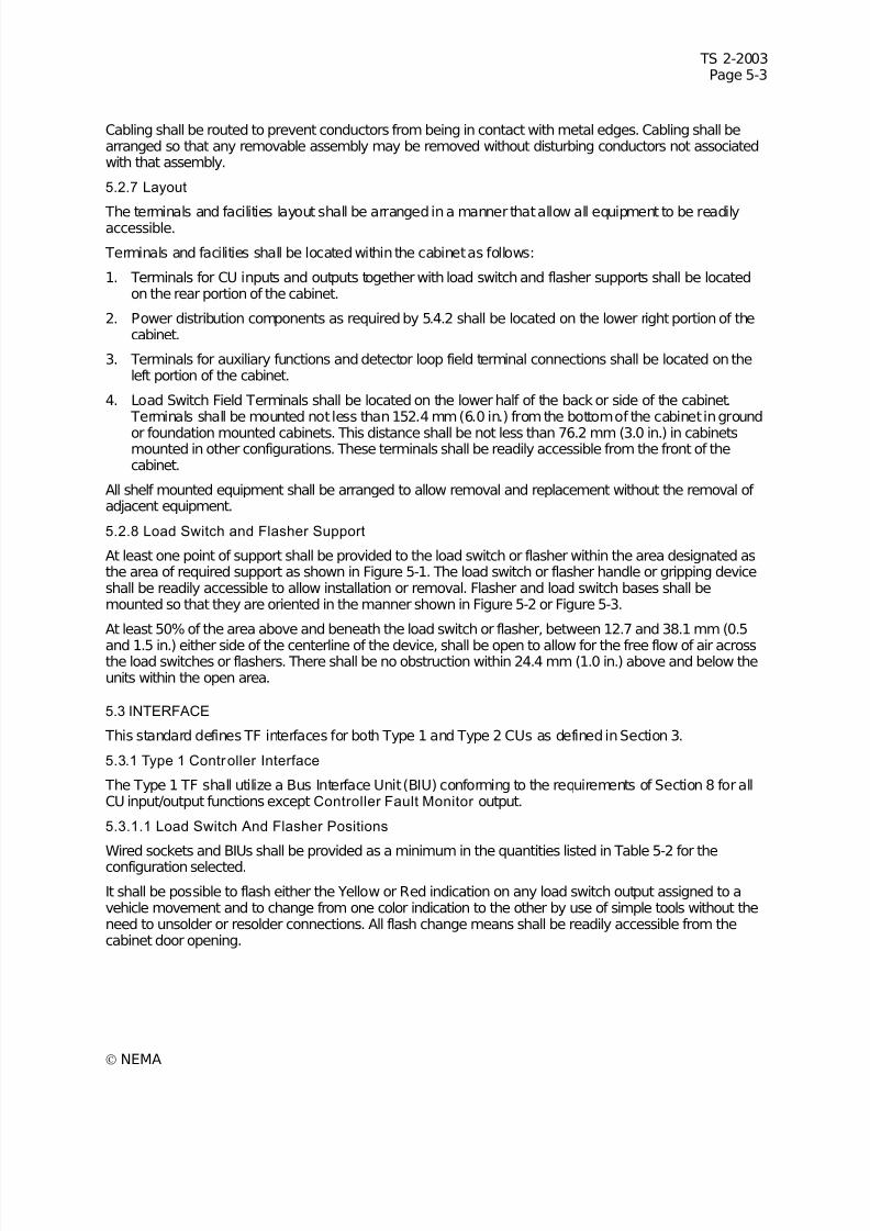
7/30/2019 NEMA TS2-2003- Traffic Controller Assemb
http://slidepdf.com/reader/full/nema-ts2-2003-traffic-controller-assemb 183/246
TS 2-2003Page 5-3
© NEMA
Cabling shall be routed to prevent conductors from being in contact with metal edges. Cabling shall bearranged so that any removable assembly may be removed without disturbing conductors not associatedwith that assembly.
5.2.7 Layout
The terminals and facilities layout shall be arranged in a manner that allow all equipment to be readilyaccessible.
Terminals and facilities shall be located within the cabinet as follows:
1. Terminals for CU inputs and outputs together with load switch and flasher supports shall be locatedon the rear portion of the cabinet.
2. Power distribution components as required by 5.4.2 shall be located on the lower right portion of thecabinet.
3. Terminals for auxiliary functions and detector loop field terminal connections shall be located on theleft portion of the cabinet.
4. Load Switch Field Terminals shall be located on the lower half of the back or side of the cabinet. Terminals shall be mounted not less than 152.4 mm (6.0 in.) from the bottom of the cabinet in ground
or foundation mounted cabinets. This distance shall be not less than 76.2 mm (3.0 in.) in cabinetsmounted in other configurations. These terminals shall be readily accessible from the front of thecabinet.
All shelf mounted equipment shall be arranged to allow removal and replacement without the removal of adjacent equipment.
5.2.8 Load Switch and Flasher Support
At least one point of support shall be provided to the load switch or flasher within the area designated asthe area of required support as shown in Figure 5-1. The load switch or flasher handle or gripping deviceshall be readily accessible to allow installation or removal. Flasher and load switch bases shall bemounted so that they are oriented in the manner shown in Figure 5-2 or Figure 5-3.
At least 50% of the area above and beneath the load switch or flasher, between 12.7 and 38.1 mm (0.5
and 1.5 in.) either side of the centerline of the device, shall be open to allow for the free flow of air acrossthe load switches or flashers. There shall be no obstruction within 24.4 mm (1.0 in.) above and below theunits within the open area.
5.3 INTERFACE
This standard defines TF interfaces for both Type 1 and Type 2 CUs as defined in Section 3.
5.3.1 Type 1 Controller Interface
The Type 1 TF shall utilize a Bus Interface Unit (BIU) conforming to the requirements of Section 8 for allCU input/output functions except Controller Fault Monitor output.
5.3.1.1 Load Switch And Flasher Positions
Wired sockets and BIUs shall be provided as a minimum in the quantities listed in Table 5-2 for the
configuration selected.
It shall be possible to flash either the Yellow or Red indication on any load switch output assigned to avehicle movement and to change from one color indication to the other by use of simple tools without theneed to unsolder or resolder connections. All flash change means shall be readily accessible from thecabinet door opening.
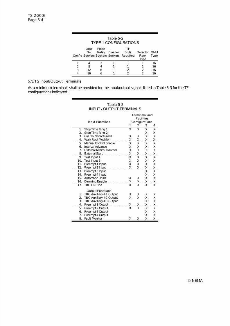
7/30/2019 NEMA TS2-2003- Traffic Controller Assemb
http://slidepdf.com/reader/full/nema-ts2-2003-traffic-controller-assemb 184/246
TS 2-2003Page 5-4
© NEMA
Table 5-2TYPE 1 CONFIGURATIONS
Config
LoadSw.
Sockets
FlashRelay
Sockets
Flasher
Sockets
TFBIUs
Required
Detector
RackType
MMU
Type
1 4 2 1 1 1 162 8 4 1 1 1 163 12 6 1 2 2 164 16 6 1 2 2 16
5.3.1.2 Input/Output Terminals
As a minimum terminals shall be provided for the input/output signals listed in Table 5-3 for the TFconfigurations indicated.
Table 5-3INPUT / OUTPUT TERMINALS
Input Functions
Terminals andFacilities
Configurations 1 2 3 4
1. Stop Time Ring 1 X X X X2. Stop Time Ring 2 X X3. Call To Nonactuated I X X X X4. Walk Rest Modifier X X X X5. Manual Control Enable X X X X6. Interval Advance X X X X7. External Minimum Recall X X X X8. External Start X X X X9. Test Input A X X X X
10. Test Input B X X X X11. Preempt 1 Input X X X X12. Preempt 2 Input X X X X
13. Preempt 3 Input X X14. Preempt 4 Input X X15. Automatic Flash X X X X16. Dimming Enable X X X X17. TBC ON Line X X X X
Output Functions 1. TBC Auxiliary #1 Output X X X X2. TBC Auxiliary #2 Output X X X X3. TBC Auxiliary #3 Output X X4. Preempt 1 Output X X X X5. Preempt 2 Output X X X X6. Preempt 3 Output X X7. Preempt 4 Output X X8. Fault Monitor X X X X
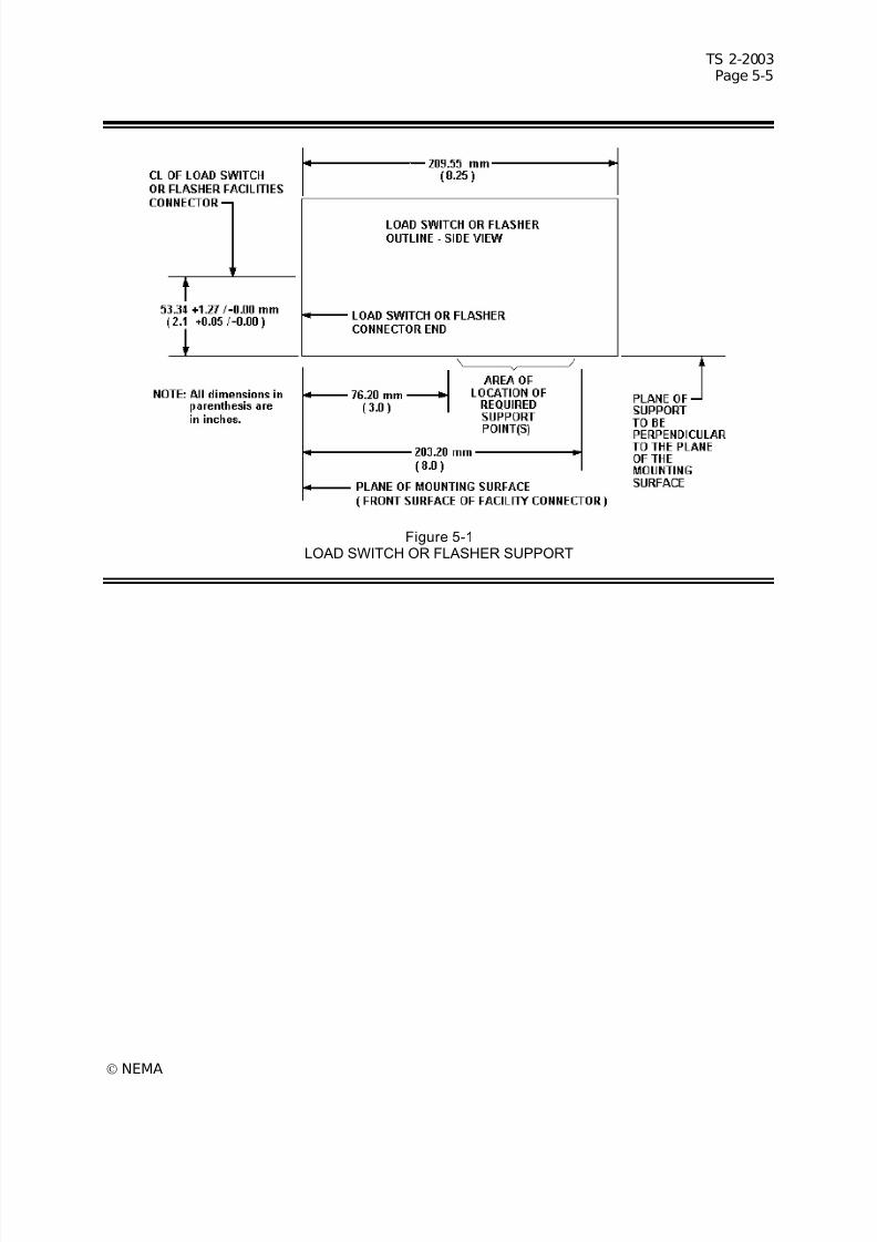
7/30/2019 NEMA TS2-2003- Traffic Controller Assemb
http://slidepdf.com/reader/full/nema-ts2-2003-traffic-controller-assemb 185/246
TS 2-2003Page 5-5
© NEMA
Figure 5-1LOAD SWITCH OR FLASHER SUPPORT
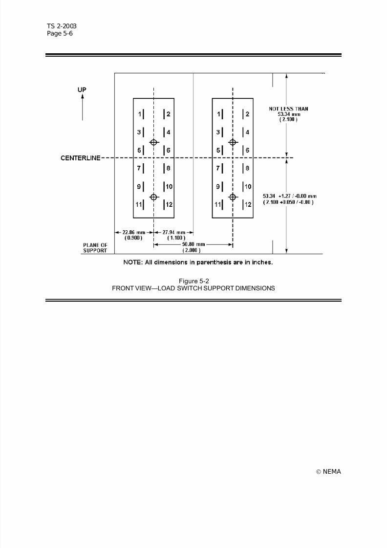
7/30/2019 NEMA TS2-2003- Traffic Controller Assemb
http://slidepdf.com/reader/full/nema-ts2-2003-traffic-controller-assemb 186/246
TS 2-2003Page 5-6
© NEMA
Figure 5-2
FRONT VIEW—LOAD SWITCH SUPPORT DIMENSIONS
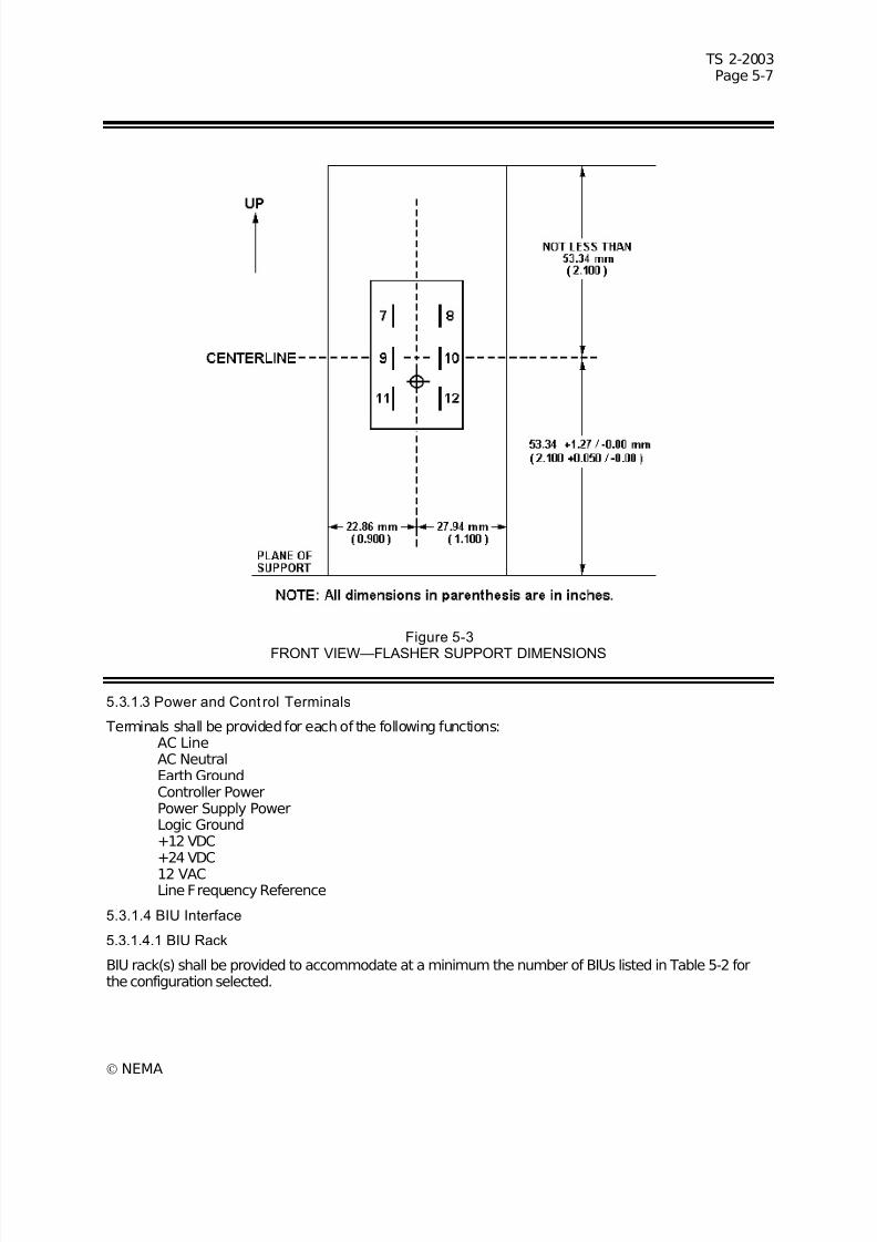
7/30/2019 NEMA TS2-2003- Traffic Controller Assemb
http://slidepdf.com/reader/full/nema-ts2-2003-traffic-controller-assemb 187/246

7/30/2019 NEMA TS2-2003- Traffic Controller Assemb
http://slidepdf.com/reader/full/nema-ts2-2003-traffic-controller-assemb 188/246
TS 2-2003Page 5-8
© NEMA
The BIU rack design shall accommodate BIU units as defined in Section 8. A dual row 64 pin female DIN41612 Type B connector shall be provided for each BIU rack position. Card guides shall be provided forboth edges of the BIU (reference Figure 8-1). Each BIU rack position shall be labeled with the BIUnumber corresponding to the associated BIU functions. The BIU address pins for each BIU rack positionconnector shall be connected to correspond to the BIU number as shown in Table 5-4.
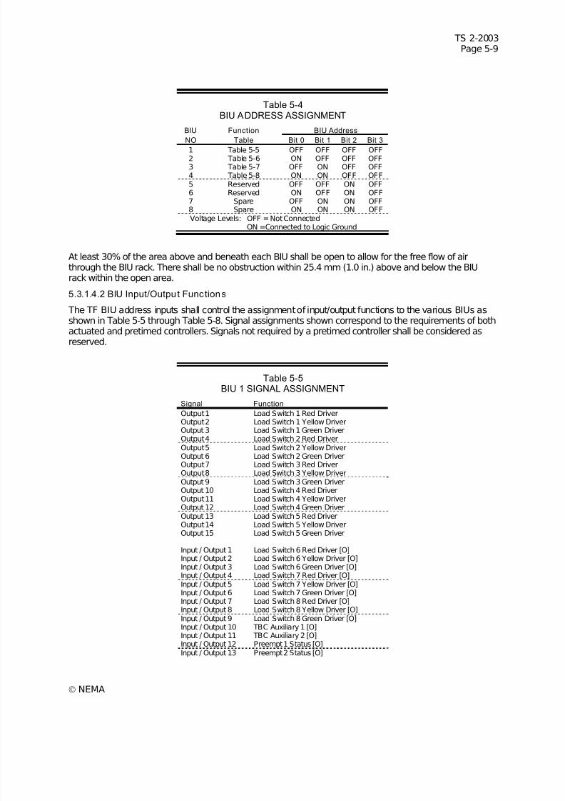
7/30/2019 NEMA TS2-2003- Traffic Controller Assemb
http://slidepdf.com/reader/full/nema-ts2-2003-traffic-controller-assemb 189/246
TS 2-2003Page 5-9
© NEMA
Table 5-4BIU ADDRESS ASSIGNMENT
BIU Function BIU Address
NO Table Bit 0 Bit 1 Bit 2 Bit 31 Table 5-5 OFF OFF OFF OFF 2 Table 5-6 ON OFF OFF OFF3 Table 5-7 OFF ON OFF OFF4 Table 5-8 ON ON OFF OFF5 Reserved OFF OFF ON OFF6 Reserved ON OFF ON OFF7 Spare OFF ON ON OFF8 Spare ON ON ON OFFVoltage Levels: OFF =Not Connected
ON =Connected to Logic Ground
At least 30% of the area above and beneath each BIU shall be open to allow for the free flow of airthrough the BIU rack. There shall be no obstruction within 25.4 mm (1.0 in.) above and below the BIU
rack within the open area.5.3.1.4.2 BIU Input/Output Functions
The TF BIU address inputs shall control the assignment of input/output functions to the various BIUs asshown in Table 5-5 through Table 5-8. Signal assignments shown correspond to the requirements of bothactuated and pretimed controllers. Signals not required by a pretimed controller shall be considered asreserved.
Table 5-5BIU 1 SIGNAL ASSIGNMENT
Signal Function
Output 1 Load Switch 1 Red Driver
Output 2 Load Switch 1 Yellow DriverOutput 3 Load Switch 1 Green DriverOutput 4 Load Switch 2 Red DriverOutput 5 Load Switch 2 Yellow DriverOutput 6 Load Switch 2 Green DriverOutput 7 Load Switch 3 Red DriverOutput 8 Load Switch 3 Yellow DriverOutput 9 Load Switch 3 Green DriverOutput 10 Load Switch 4 Red DriverOutput 11 Load Switch 4 Yellow DriverOutput 12 Load Switch 4 Green DriverOutput 13 Load Switch 5 Red DriverOutput 14 Load Switch 5 Yellow DriverOutput 15 Load Switch 5 Green Driver
Input / Output 1 Load Switch 6 Red Driver [O]
Input / Output 2 Load Switch 6 Yellow Driver [O]Input / Output 3 Load Switch 6 Green Driver [O]Input / Output 4 Load Switch 7 Red Driver [O]Input / Output 5 Load Switch 7 Yellow Driver [O]Input / Output 6 Load Switch 7 Green Driver [O]Input / Output 7 Load Switch 8 Red Driver [O]Input / Output 8 Load Switch 8 Yellow Driver [O]Input / Output 9 Load Switch 8 Green Driver [O]Input / Output 10 TBC Auxiliary 1 [O]Input / Output 11 TBC Auxiliary 2 [O]Input / Output 12 Preempt 1 Status [O]Input / Output 13 Preempt 2 Status [O]
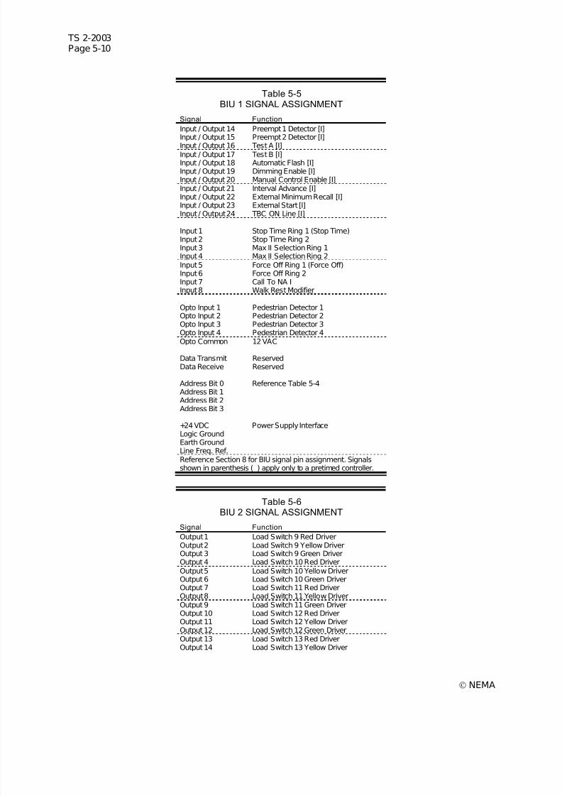
7/30/2019 NEMA TS2-2003- Traffic Controller Assemb
http://slidepdf.com/reader/full/nema-ts2-2003-traffic-controller-assemb 190/246
TS 2-2003Page 5-10
© NEMA
Table 5-5BIU 1 SIGNAL ASSIGNMENT
Signal Function
Input / Output 14 Preempt 1 Detector [I]
Input / Output 15 Preempt 2 Detector [I]Input / Output 16 Test A [I]Input / Output 17 Test B [I]Input / Output 18 Automatic Flash [I]Input / Output 19 Dimming Enable [I]Input / Output 20 Manual Control Enable [I]Input / Output 21 Interval Advance [I]Input / Output 22 External Minimum Recall [I]Input / Output 23 External Start [I]Input / Output 24 TBC ON Line [I]
Input 1 Stop Time Ring 1 (Stop Time)Input 2 Stop Time Ring 2Input 3 Max II Selection Ring 1Input 4 Max II Selection Ring 2Input 5 Force Off Ring 1 (Force Off)Input 6 Force Off Ring 2Input 7 Call To NA IInput 8 Walk Rest Modifier
Opto Input 1 Pedestrian Detector 1Opto Input 2 Pedestrian Detector 2Opto Input 3 Pedestrian Detector 3Opto Input 4 Pedestrian Detector 4Opto Common 12 VAC
Data Transmit ReservedData Receive Reserved
Address Bit 0 Reference Table 5-4Address Bit 1Address Bit 2Address Bit 3
+24 VDC Power Supply InterfaceLogic GroundEarth GroundLine Freq. Ref.Reference Section 8 for BIU signal pin assignment. Signalsshown in parenthesis ( ) apply only to a pretimed controller.
Table 5-6BIU 2 SIGNAL ASSIGNMENT
Signal Function
Output 1 Load Switch 9 Red DriverOutput 2 Load Switch 9 Yellow DriverOutput 3 Load Switch 9 Green DriverOutput 4 Load Switch 10 Red DriverOutput 5 Load Switch 10 Yellow DriverOutput 6 Load Switch 10 Green DriverOutput 7 Load Switch 11 Red DriverOutput 8 Load Switch 11 Yellow DriverOutput 9 Load Switch 11 Green DriverOutput 10 Load Switch 12 Red DriverOutput 11 Load Switch 12 Yellow DriverOutput 12 Load Switch 12 Green DriverOutput 13 Load Switch 13 Red DriverOutput 14 Load Switch 13 Yellow Driver
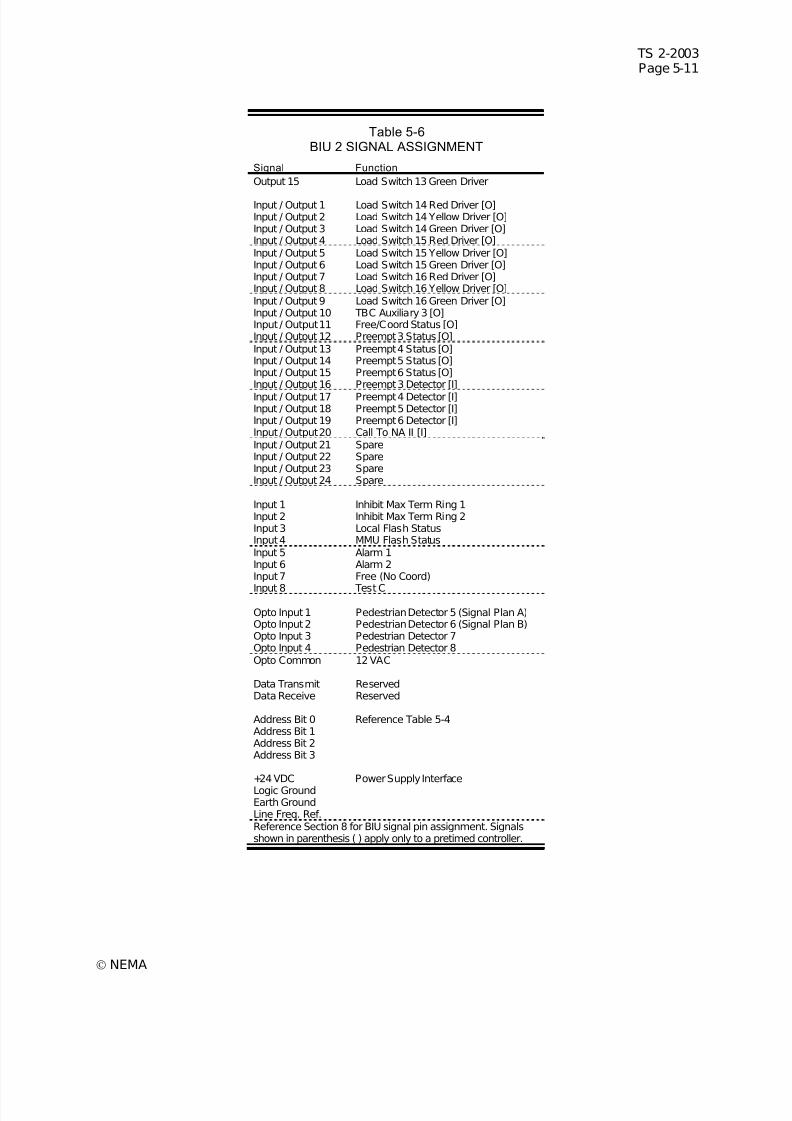
7/30/2019 NEMA TS2-2003- Traffic Controller Assemb
http://slidepdf.com/reader/full/nema-ts2-2003-traffic-controller-assemb 191/246
TS 2-2003Page 5-11
© NEMA
Table 5-6BIU 2 SIGNAL ASSIGNMENT
Signal Function
Output 15 Load Switch 13 Green Driver
Input / Output 1 Load Switch 14 Red Driver [O]Input / Output 2 Load Switch 14 Yellow Driver [O]Input / Output 3 Load Switch 14 Green Driver [O]Input / Output 4 Load Switch 15 Red Driver [O]Input / Output 5 Load Switch 15 Yellow Driver [O]Input / Output 6 Load Switch 15 Green Driver [O]Input / Output 7 Load Switch 16 Red Driver [O]Input / Output 8 Load Switch 16 Yellow Driver [O]Input / Output 9 Load Switch 16 Green Driver [O]Input / Output 10 TBC Auxiliary 3 [O]Input / Output 11 Free/Coord Status [O]Input / Output 12 Preempt 3 Status [O]Input / Output 13 Preempt 4 Status [O]Input / Output 14 Preempt 5 Status [O]Input / Output 15 Preempt 6 Status [O]Input / Output 16 Preempt 3 Detector [I]Input / Output 17 Preempt 4 Detector [I]Input / Output 18 Preempt 5 Detector [I]Input / Output 19 Preempt 6 Detector [I]Input / Output 20 Call To NA II [I]Input / Output 21 SpareInput / Output 22 SpareInput / Output 23 SpareInput / Output 24 Spare
Input 1 Inhibit Max Term Ring 1Input 2 Inhibit Max Term Ring 2Input 3 Local Flash StatusInput 4 MMU Flash StatusInput 5 Alarm 1Input 6 Alarm 2Input 7 Free (No Coord)
Input 8 Test C
Opto Input 1 Pedestrian Detector 5 (Signal Plan A)Opto Input 2 Pedestrian Detector 6 (Signal Plan B)Opto Input 3 Pedestrian Detector 7Opto Input 4 Pedestrian Detector 8Opto Common 12 VAC
Data Transmit ReservedData Receive Reserved
Address Bit 0 Reference Table 5-4Address Bit 1Address Bit 2Address Bit 3
+24 VDC Power Supply InterfaceLogic GroundEarth GroundLine Freq. Ref.Reference Section 8 for BIU signal pin assignment. Signalsshown in parenthesis ( ) apply only to a pretimed controller.
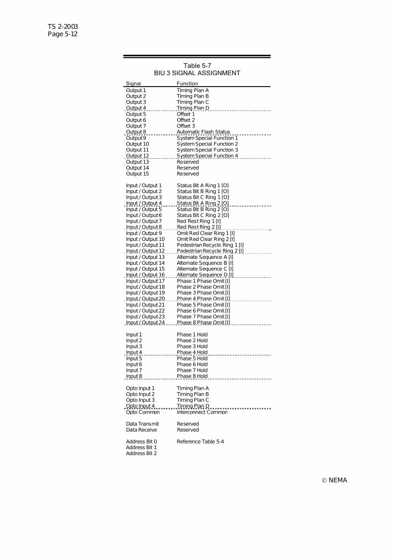
7/30/2019 NEMA TS2-2003- Traffic Controller Assemb
http://slidepdf.com/reader/full/nema-ts2-2003-traffic-controller-assemb 192/246
TS 2-2003Page 5-12
© NEMA
Table 5-7BIU 3 SIGNAL ASSIGNMENT
Signal Function
Output 1 Timing Plan A
Output 2 Timing Plan BOutput 3 Timing Plan COutput 4 Timing Plan DOutput 5 Offset 1Output 6 Offset 2Output 7 Offset 3Output 8 Automatic Flash StatusOutput 9 System Special Function 1Output 10 System Special Function 2Output 11 System Special Function 3Output 12 System Special Function 4Output 13 ReservedOutput 14 ReservedOutput 15 Reserved
Input / Output 1 Status Bit A Ring 1 [O]Input / Output 2 Status Bit B Ring 1 [O]Input / Output 3 Status Bit C Ring 1 [O]Input / Output 4 Status Bit A Ring 2 [O]Input / Output 5 Status Bit B Ring 2 [O]Input / Output 6 Status Bit C Ring 2 [O]Input / Output 7 Red Rest Ring 1 [I]Input / Output 8 Red Rest Ring 2 [I]Input / Output 9 Omit Red Clear Ring 1 [I]Input / Output 10 Omit Red Clear Ring 2 [I]Input / Output 11 Pedestrian Recycle Ring 1 [I]Input / Output 12 Pedestrian Recycle Ring 2 [I]Input / Output 13 Alternate Sequence A [I]Input / Output 14 Alternate Sequence B [I]Input / Output 15 Alternate Sequence C [I]Input / Output 16 Alternate Sequence D [I]Input / Output 17 Phase 1 Phase Omit [I]Input / Output 18 Phase 2 Phase Omit [I]
Input / Output 19 Phase 3 Phase Omit [I]Input / Output 20 Phase 4 Phase Omit [I]Input / Output 21 Phase 5 Phase Omit [I]Input / Output 22 Phase 6 Phase Omit [I]Input / Output 23 Phase 7 Phase Omit [I]Input / Output 24 Phase 8 Phase Omit [I]
Input 1 Phase 1 HoldInput 2 Phase 2 HoldInput 3 Phase 3 HoldInput 4 Phase 4 HoldInput 5 Phase 5 HoldInput 6 Phase 6 HoldInput 7 Phase 7 HoldInput 8 Phase 8 Hold
Opto Input 1 Timing Plan AOpto Input 2 Timing Plan BOpto Input 3 Timing Plan COpto Input 4 Timing Plan DOpto Common Interconnect Common
Data Transmit ReservedData Receive Reserved
Address Bit 0 Reference Table 5-4Address Bit 1Address Bit 2
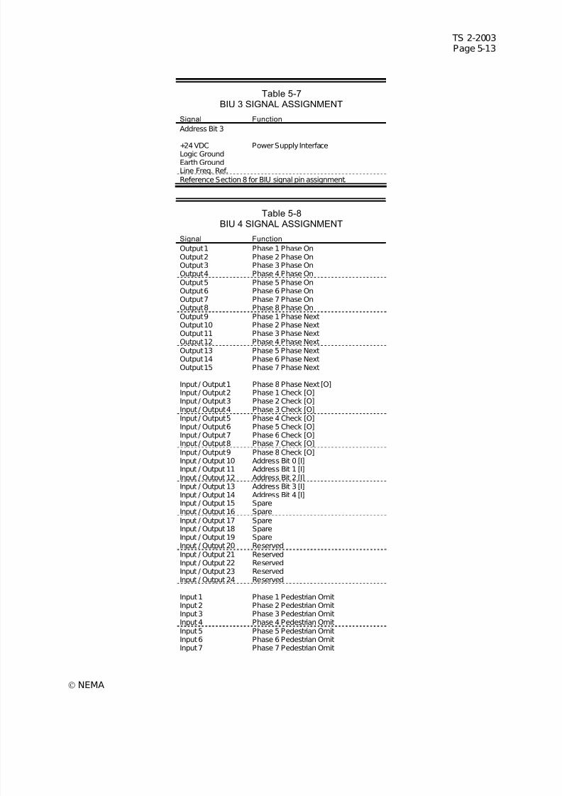
7/30/2019 NEMA TS2-2003- Traffic Controller Assemb
http://slidepdf.com/reader/full/nema-ts2-2003-traffic-controller-assemb 193/246
TS 2-2003Page 5-13
© NEMA
Table 5-7BIU 3 SIGNAL ASSIGNMENT
Signal Function
Address Bit 3
+24 VDC Power Supply InterfaceLogic GroundEarth GroundLine Freq. Ref.Reference Section 8 for BIU signal pin assignment.
Table 5-8BIU 4 SIGNAL ASSIGNMENT
Signal Function
Output 1 Phase 1 Phase OnOutput 2 Phase 2 Phase OnOutput 3 Phase 3 Phase OnOutput 4 Phase 4 Phase OnOutput 5 Phase 5 Phase OnOutput 6 Phase 6 Phase OnOutput 7 Phase 7 Phase OnOutput 8 Phase 8 Phase OnOutput 9 Phase 1 Phase NextOutput 10 Phase 2 Phase NextOutput 11 Phase 3 Phase NextOutput 12 Phase 4 Phase NextOutput 13 Phase 5 Phase NextOutput 14 Phase 6 Phase NextOutput 15 Phase 7 Phase Next
Input / Output 1 Phase 8 Phase Next [O]Input / Output 2 Phase 1 Check [O]Input / Output 3 Phase 2 Check [O]Input / Output 4 Phase 3 Check [O]
Input / Output 5 Phase 4 Check [O]Input / Output 6 Phase 5 Check [O]Input / Output 7 Phase 6 Check [O]Input / Output 8 Phase 7 Check [O]Input / Output 9 Phase 8 Check [O]Input / Output 10 Address Bit 0 [I]Input / Output 11 Address Bit 1 [I]Input / Output 12 Address Bit 2 [I]Input / Output 13 Address Bit 3 [I]Input / Output 14 Address Bit 4 [I]Input / Output 15 SpareInput / Output 16 SpareInput / Output 17 SpareInput / Output 18 SpareInput / Output 19 SpareInput / Output 20 Reserved
Input / Output 21 ReservedInput / Output 22 ReservedInput / Output 23 ReservedInput / Output 24 Reserved
Input 1 Phase 1 Pedestrian OmitInput 2 Phase 2 Pedestrian OmitInput 3 Phase 3 Pedestrian OmitInput 4 Phase 4 Pedestrian OmitInput 5 Phase 5 Pedestrian OmitInput 6 Phase 6 Pedestrian OmitInput 7 Phase 7 Pedestrian Omit
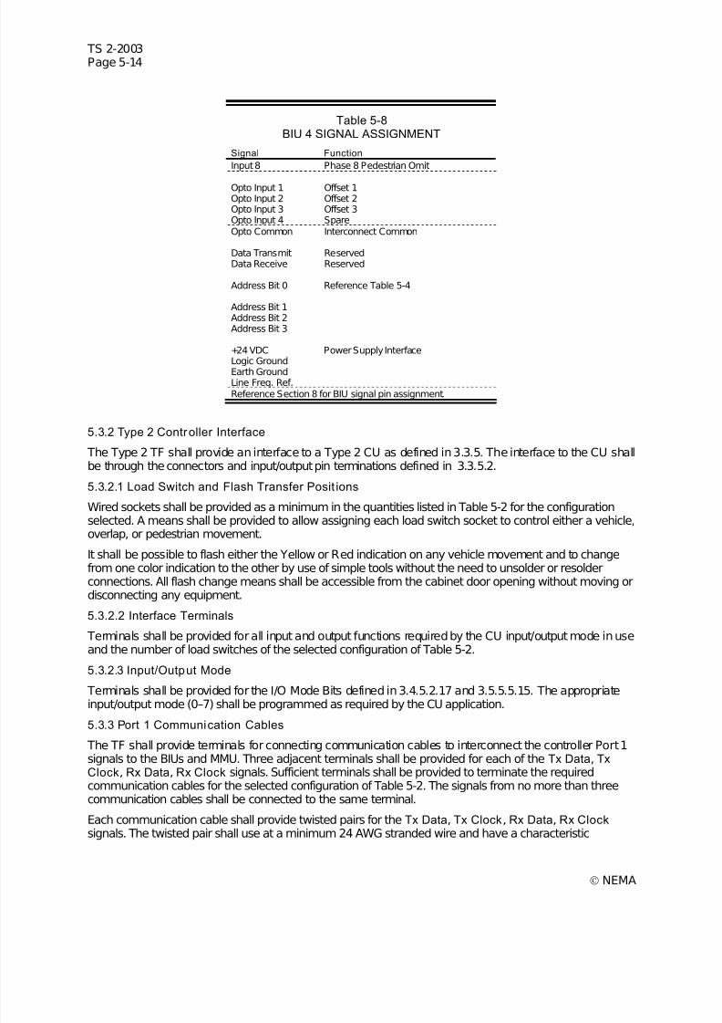
7/30/2019 NEMA TS2-2003- Traffic Controller Assemb
http://slidepdf.com/reader/full/nema-ts2-2003-traffic-controller-assemb 194/246
TS 2-2003Page 5-14
© NEMA
Table 5-8BIU 4 SIGNAL ASSIGNMENT
Signal Function
Input 8 Phase 8 Pedestrian Omit
Opto Input 1 Offset 1Opto Input 2 Offset 2Opto Input 3 Offset 3Opto Input 4 SpareOpto Common Interconnect Common
Data Transmit ReservedData Receive Reserved
Address Bit 0 Reference Table 5-4
Address Bit 1Address Bit 2Address Bit 3
+24 VDC Power Supply Interface
Logic GroundEarth GroundLine Freq. Ref.Reference Section 8 for BIU signal pin assignment.
5.3.2 Type 2 Controller Interface
The Type 2 TF shall provide an interface to a Type 2 CU as defined in 3.3.5. The interface to the CU shallbe through the connectors and input/output pin terminations defined in 3.3.5.2.
5.3.2.1 Load Switch and Flash Transfer Posit ions
Wired sockets shall be provided as a minimum in the quantities listed in Table 5-2 for the configurationselected. A means shall be provided to allow assigning each load switch socket to control either a vehicle,
overlap, or pedestrian movement.It shall be possible to flash either the Yellow or Red indication on any vehicle movement and to changefrom one color indication to the other by use of simple tools without the need to unsolder or resolderconnections. All flash change means shall be accessible from the cabinet door opening without moving ordisconnecting any equipment.
5.3.2.2 Interface Terminals
Terminals shall be provided for all input and output functions required by the CU input/output mode in useand the number of load switches of the selected configuration of Table 5-2.
5.3.2.3 Input/Output Mode
Terminals shall be provided for the I/O Mode Bits defined in 3.4.5.2.17 and 3.5.5.5.15. The appropriateinput/output mode (0–7) shall be programmed as required by the CU application.
5.3.3 Port 1 Communication Cables
The TF shall provide terminals for connecting communication cables to interconnect the controller Port 1signals to the BIUs and MMU. Three adjacent terminals shall be provided for each of the Tx Data, TxClock, Rx Data, Rx Clock signals. Sufficient terminals shall be provided to terminate the requiredcommunication cables for the selected configuration of Table 5-2. The signals from no more than threecommunication cables shall be connected to the same terminal.
Each communication cable shall provide twisted pairs for the Tx Data, Tx Clock, Rx Data, Rx Clock signals. The twisted pair shall use at a minimum 24 AWG stranded wire and have a characteristic
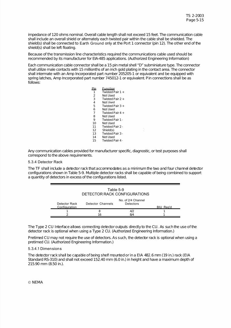
7/30/2019 NEMA TS2-2003- Traffic Controller Assemb
http://slidepdf.com/reader/full/nema-ts2-2003-traffic-controller-assemb 195/246
TS 2-2003Page 5-15
© NEMA
impedance of 120 ohms nominal. Overall cable length shall not exceed 15 feet. The communication cableshall include an overall shield or alternately each twisted pair within the cable shall be shielded. Theshield(s) shall be connected to Earth Ground only at the Port 1 connector (pin 12). The other end of theshield(s) shall be left floating.
Because of the transmission line characteristics required the communications cable used should be
recommended by its manufacturer for EIA-485 applications. (Authorized Engineering Information)
Each communication cable connector shall be a 15 pin metal shell “D” subminiature type. The connectorshall utilize male contacts with 15 millionths of an inch gold plating in the contact area. The connectorshall intermate with an Amp Incorporated part number 205205-1 or equivalent and be equipped withspring latches, Amp Incorporated part number 745012-1 or equivalent. Pin connections shall be asfollows:
Pin Function 1 Twisted Pair 1 +2 Not Used3 Twisted Pair 2 +4 Not Used5 Twisted Pair 3 +6 Not Used7 Twisted Pair 4 +8 Not Used9 Twisted Pair 1 -10 Not Used11 Twisted Pair 2 -12 Shield(s)13 Twisted Pair 3 -14 Not Used15 Twisted Pair 4 -
Any communication cables provided for manufacturer specific, diagnostic, or test purposes shallcorrespond to the above requirements.
5.3.4 Detector Rack
The TF shall include a detector rack that accommodates as a minimum the two and four channel detector
configurations shown in Table 5-9. Multiple detector racks shall be capable of being combined to supporta quantity of detectors in excess of the configurations listed.
Table 5-9DETECTOR RACK CONFIGURATIONS
Detector RackConfiguration
Detector Channels No. of 2/4 Channel
Detectors BIU Req'd
1 8 4/2 12 16 8/4 1
The Type 2 CU Interface allows connecting detector outputs directly to the CU. As such the use of the
detector rack is optional when using a Type 2 CU. (Authorized Engineering Information.)
Pretimed CU may not require the use of detectors. As such, the detector rack is optional when using apretimed CU. (Authorized Engineering Information.)
5.3.4.1 Dimensions
The detector rack shall be capable of being shelf mounted or in a EIA 482.6 mm (19 in.) rack (EIAStandard RS-310) and shall not exceed 152.40 mm (6.0 in.) in height and have a maximum depth of 215.90 mm (8.50 in.).
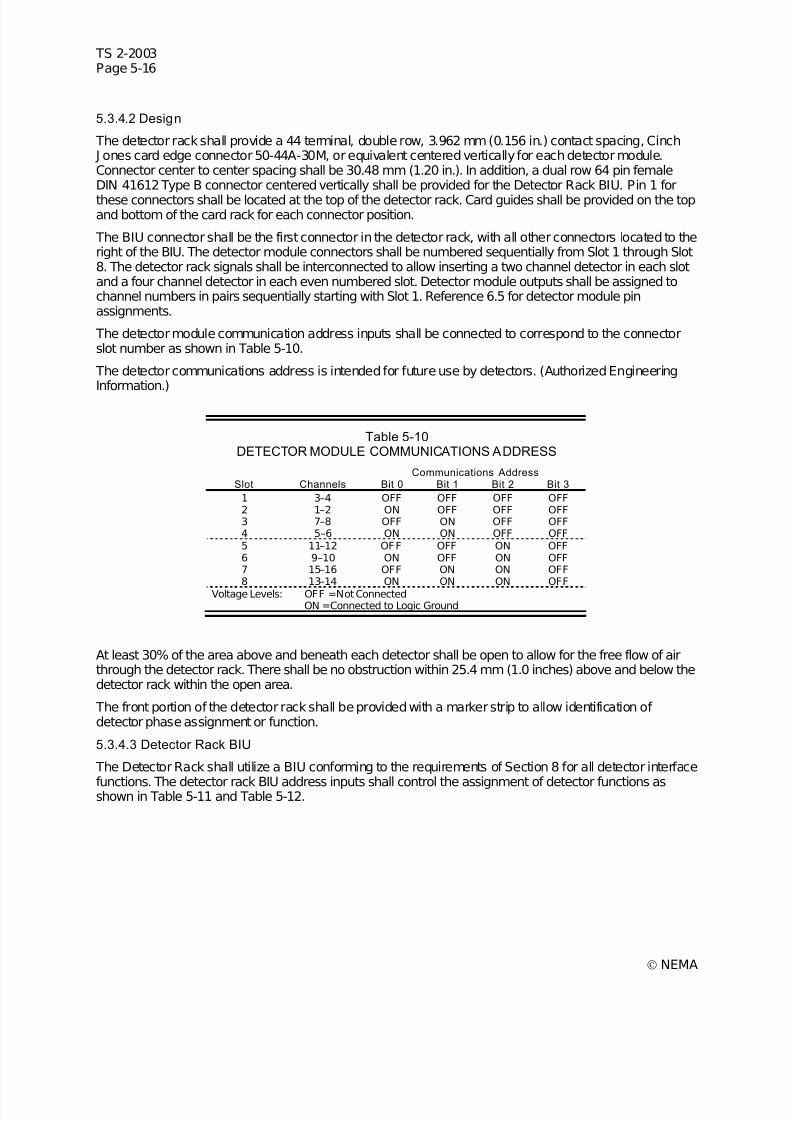
7/30/2019 NEMA TS2-2003- Traffic Controller Assemb
http://slidepdf.com/reader/full/nema-ts2-2003-traffic-controller-assemb 196/246
TS 2-2003Page 5-16
© NEMA
5.3.4.2 Design
The detector rack shall provide a 44 terminal, double row, 3.962 mm (0.156 in.) contact spacing, Cinch J ones card edge connector 50-44A-30M, or equivalent centered vertically for each detector module.Connector center to center spacing shall be 30.48 mm (1.20 in.). In addition, a dual row 64 pin femaleDIN 41612 Type B connector centered vertically shall be provided for the Detector Rack BIU. Pin 1 for
these connectors shall be located at the top of the detector rack. Card guides shall be provided on the topand bottom of the card rack for each connector position.
The BIU connector shall be the first connector in the detector rack, with all other connectors located to theright of the BIU. The detector module connectors shall be numbered sequentially from Slot 1 through Slot8. The detector rack signals shall be interconnected to allow inserting a two channel detector in each slotand a four channel detector in each even numbered slot. Detector module outputs shall be assigned tochannel numbers in pairs sequentially starting with Slot 1. Reference 6.5 for detector module pinassignments.
The detector module communication address inputs shall be connected to correspond to the connectorslot number as shown in Table 5-10.
The detector communications address is intended for future use by detectors. (Authorized Engineering
Information.)
Table 5-10DETECTOR MODULE COMMUNICATIONS ADDRESS
Communications AddressSlot Channels Bit 0 Bit 1 Bit 2 Bit 3
1 3–4 OFF OFF OFF OFF2 1–2 ON OFF OFF OFF3 7–8 OFF ON OFF OFF4 5–6 ON ON OFF OFF5 11–12 OFF OFF ON OFF6 9–10 ON OFF ON OFF7 15–16 OFF ON ON OFF8 13–14 ON ON ON OFF
Voltage Levels: OFF =Not ConnectedON =Connected to Logic Ground
At least 30% of the area above and beneath each detector shall be open to allow for the free flow of airthrough the detector rack. There shall be no obstruction within 25.4 mm (1.0 inches) above and below thedetector rack within the open area.
The front portion of the detector rack shall be provided with a marker strip to allow identification of detector phase assignment or function.
5.3.4.3 Detector Rack BIU
The Detector Rack shall utilize a BIU conforming to the requirements of Section 8 for all detector interface
functions. The detector rack BIU address inputs shall control the assignment of detector functions asshown in Table 5-11 and Table 5-12.
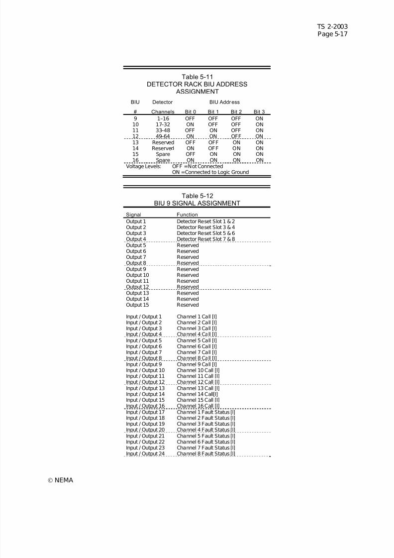
7/30/2019 NEMA TS2-2003- Traffic Controller Assemb
http://slidepdf.com/reader/full/nema-ts2-2003-traffic-controller-assemb 197/246
TS 2-2003Page 5-17
© NEMA
Table 5-11DETECTOR RACK BIU ADDRESS
ASSIGNMENT
BIU Detector BIU Address
# Channels Bit 0 Bit 1 Bit 2 Bit 3
9 1–16 OFF OFF OFF ON10 17–32 ON OFF OFF ON11 33–48 OFF ON OFF ON12 49–64 ON ON OFF ON13 Reserved OFF OFF ON ON14 Reserved ON OFF ON ON15 Spare OFF ON ON ON16 Spare ON ON ON ON
Voltage Levels: OFF =Not ConnectedON =Connected to Logic Ground
Table 5-12BIU 9 SIGNAL ASSIGNMENT
Signal Function
Output 1 Detector Reset Slot 1 & 2Output 2 Detector Reset Slot 3 & 4Output 3 Detector Reset Slot 5 & 6Output 4 Detector Reset Slot 7 & 8Output 5 ReservedOutput 6 ReservedOutput 7 ReservedOutput 8 ReservedOutput 9 ReservedOutput 10 ReservedOutput 11 ReservedOutput 12 Reserved
Output 13 ReservedOutput 14 ReservedOutput 15 Reserved
Input / Output 1 Channel 1 Call [I]Input / Output 2 Channel 2 Call [I]Input / Output 3 Channel 3 Call [I]Input / Output 4 Channel 4 Call [I]Input / Output 5 Channel 5 Call [I]Input / Output 6 Channel 6 Call [I]Input / Output 7 Channel 7 Call [I]Input / Output 8 Channel 8 Call [I]Input / Output 9 Channel 9 Call [I]Input / Output 10 Channel 10 Call [I]Input / Output 11 Channel 11 Call [I]Input / Output 12 Channel 12 Call [I]
Input / Output 13 Channel 13 Call [I]Input / Output 14 Channel 14 Call[I]Input / Output 15 Channel 15 Call [I]Input / Output 16 Channel 16 Call [I]Input / Output 17 Channel 1 Fault Status [I]Input / Output 18 Channel 2 Fault Status [I]Input / Output 19 Channel 3 Fault Status [I]Input / Output 20 Channel 4 Fault Status [I]Input / Output 21 Channel 5 Fault Status [I]Input / Output 22 Channel 6 Fault Status [I]Input / Output 23 Channel 7 Fault Status [I]Input / Output 24 Channel 8 Fault Status [I]
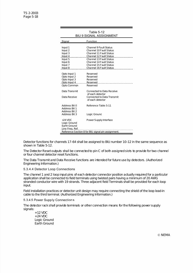
7/30/2019 NEMA TS2-2003- Traffic Controller Assemb
http://slidepdf.com/reader/full/nema-ts2-2003-traffic-controller-assemb 198/246
TS 2-2003Page 5-18
© NEMA
Table 5-12BIU 9 SIGNAL ASSIGNMENT
Signal Function
Input 1 Channel 9 Fault StatusInput 2 Channel 10 Fault StatusInput 3 Channel 11 Fault StatusInput 4 Channel 12 Fault StatusInput 5 Channel 13 Fault StatusInput 6 Channel 14 Fault StatusInput 7 Channel 15 Fault StatusInput 8 Channel 16 Fault Status
Opto Input 1 ReservedOpto Input 2 ReservedOpto Input 3 ReservedOpto Input 4 ReservedOpto Common Reserved
Data Transmit Connected to Data Receiveof each detector
Data Receive Connected to Data Transmitof each detector
Address Bit 0 Reference Table 5-11Address Bit 1Address Bit 2Address Bit 3 Logic Ground
+24 VDC Power Supply InterfaceLogic GroundEarth GroundLine Freq. Ref.Reference Section 8 for BIU signal pin assignment.
Detector functions for channels 17–64 shall be assigned to BIU number 10–12 in the same sequence asshown in Table 5-12.
The Detector Reset outputs shall be connected to pin C of both assigned slots to provide for two channelor four channel detector reset functions.
The Data Transmit and Data Receive functions are intended for future use by detectors. (AuthorizedEngineering Information.)
5.3.4.4 Detector Loop Connections
The channel 1 and 2 loop input pins of each detector connector position actually required for a particularapplication shall be connected to field terminals using twisted pairs having a minimum of 20 AWGstranded conductor wire with 19 strands. Three adjacent field Terminals shall be provided for each loopinput.
Field installation practices or detector unit design may require connecting the shield of the loop lead-incable to the third terminal. (Authorized Engineering Information.)
5.3.4.5 Power Supply Connect ions
The detector rack shall provide terminals or other connection means for the following power supplysignals:
+12 VDC+24 VDCLogic GroundEarth Ground
7/30/2019 NEMA TS2-2003- Traffic Controller Assemb
http://slidepdf.com/reader/full/nema-ts2-2003-traffic-controller-assemb 199/246
TS 2-2003Page 5-19
© NEMA
Line Frequency Reference
The +12 VDC is intended to provide power only to detectors. (Authorized Engineering Information.)
5.3.5 Power Supply
The TF shall include a power supply to provide regulated DC power, unregulated AC power, and a linefrequency reference for the Detector rack, BIUs, load switches, and other auxiliary equipment.
The Type 2 Controller interface provides 500 milliamps of +24 VDC power. As such the use of the cabinetpower supply is optional when using a Type 2 controller. (Authorized Engineering Information.)
5.3.5.1 Dimensions
The power supply shall be capable of being shelf mounted or in an EIA 486.2 mm (19 inches) rack (EIAStandard RS-310). The power supply shall not exceed 152.40 mm (6 inch) in height and have amaximum depth of 215.90 mm (8.50 inches) including connectors, harnesses and protrusions.
5.3.5.2 Environmental Requirements
The power supply shall perform its specified functions under the environmental conditions set forth inSection 2.
5.3.5.3 Electrical Requirements
1. The power supply shall provide positive 12 +1 volts and 24 +2 volts DC power regulated over an ACLine voltage variation from 89 volts to 135 volts from 1/8 load to full load and unregulated 12 voltsAC. The unregulated voltage shall nominally measure 12 volts with an AC Line voltage of 120 voltsand shall be no less than 7.5 volts with an AC Line voltage of 89 volts.
2. Minimum average continuous current capability shall be as shown below with DC voltages havingless than 0.5 volts peak-to-peak ripple:
+12 VDC 2.0 Amps+24 VDC 2.0 Amps12 VAC 0.250 Amps
Voltage regulation does not have to be maintained if current exceeds values shown.
The +12 VDC is intended to provide power only to detectors. (Authorized Engineering Information.)
3. Under full load conditions the power supply shall provide 50 milliseconds of hold up time for +12 VDCand +24 VDC upon loss of AC Line voltage. During the hold up period the +12 VDC shall not dropbelow +10.8 VDC and the +24 VDC shall not drop below +18 VDC.
4. The +12 VDC and +24 VDC outputs shall withstand a 10 millisecond 10 ampere load surge.
5. The front panel of the power supply shall include over current protection devices for the AC Line andall output voltages.
6. A line frequency output shall provide a reference to the AC Line frequency. This output shall alternateat the line frequency (nominally 60 pulses per second) and shall be True in phase with the positivehalf cycle and shall switch within 5 degrees of the zero crossing point of the AC Line.
The line frequency output shall have the following characteristics:
a. Shall be capable of providing 50 milliamperes of current in the False state.
b. Current sinking capability in the True state shall be a minimum of 50 milliamperes.
c. The output shall have a rise and fall time of no greater than 50 microseconds when switching aload capacitance of 10,000 picofarads.
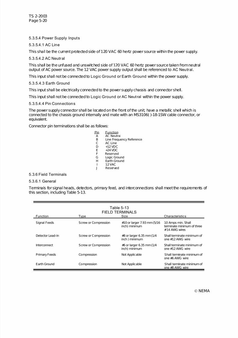
7/30/2019 NEMA TS2-2003- Traffic Controller Assemb
http://slidepdf.com/reader/full/nema-ts2-2003-traffic-controller-assemb 200/246
TS 2-2003Page 5-20
© NEMA
5.3.5.4 Power Supply Inputs
5.3.5.4.1 AC Line
This shall be the current protected side of 120 VAC 60 hertz power source within the power supply.
5.3.5.4.2 AC Neutral This shall be the unfused and unswitched side of 120 VAC 60 hertz power source taken from neutraloutput of AC power source. The 12 VAC power supply output shall be referenced to AC Neutral.
This input shall not be connected to Logic Ground or Earth Ground within the power supply.
5.3.5.4.3 Earth Ground
This input shall be electrically connected to the power supply chassis and connector shell.
This input shall not be connected to Logic Ground or AC Neutral within the power supply.
5.3.5.4.4 Pin Connections
The power supply connector shall be located on the front of the unit, have a metallic shell which isconnected to the chassis ground internally and mate with an MS3106( )-18-1SW cable connector, or
equivalent.
Connector pin terminations shall be as follows:
Pin Function A AC NeutralB Line Frequency ReferenceC AC LineD +12 VDCE +24 VDCF ReservedG Logic GroundH Earth GroundI 12 VAC
J Reserved
5.3.6 Field Terminals
5.3.6.1 General
Terminals for signal heads, detectors, primary feed, and interconnections shall meet the requirements of this section, including Table 5-13.
Table 5-13FIELD TERMINALS
Function Type Size Characteristic s
Signal Feeds Screw or Compression #10 or larger 7.93 mm (5/16inch) minimum
10 Amps min. Shallterminate minimum of three#14 AWG wires
Detector Lead-In Screw or Compression #8 or larger 6.35 mm (1/4inch ) minimum Shall terminate minimum of one #12 AWG wire
Interconnect Screw or Compression #6 or larger 6.35 mm (1/4inch) minimum
Shall terminate minimum of one #12 AWG wire
Primary Feeds Compression Not Applicable Shall terminate minimum of one #6 AWG wire
Earth Ground Compression Not Applicable Shall terminate minimum of one #8 AWG wire
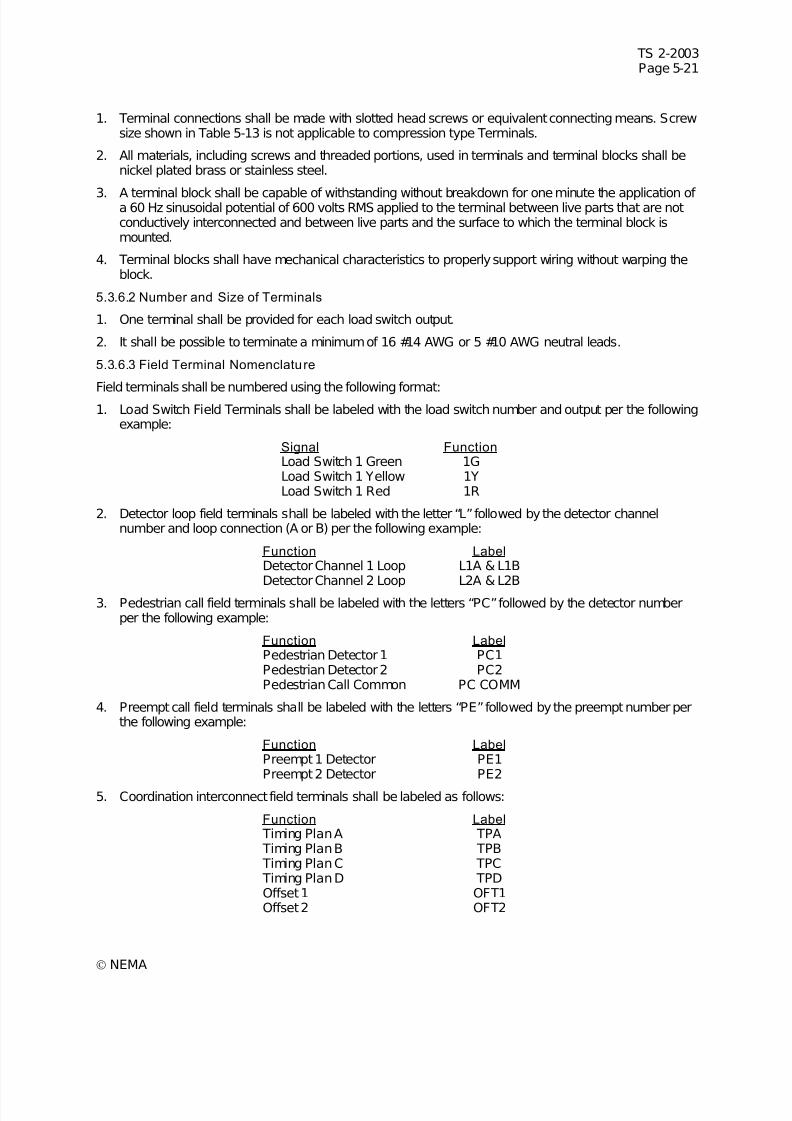
7/30/2019 NEMA TS2-2003- Traffic Controller Assemb
http://slidepdf.com/reader/full/nema-ts2-2003-traffic-controller-assemb 201/246
TS 2-2003Page 5-21
© NEMA
1. Terminal connections shall be made with slotted head screws or equivalent connecting means. Screwsize shown in Table 5-13 is not applicable to compression type Terminals.
2. All materials, including screws and threaded portions, used in terminals and terminal blocks shall benickel plated brass or stainless steel.
3. A terminal block shall be capable of withstanding without breakdown for one minute the application of a 60 Hz sinusoidal potential of 600 volts RMS applied to the terminal between live parts that are notconductively interconnected and between live parts and the surface to which the terminal block ismounted.
4. Terminal blocks shall have mechanical characteristics to properly support wiring without warping theblock.
5.3.6.2 Number and Size of Terminals
1. One terminal shall be provided for each load switch output.
2. It shall be possible to terminate a minimum of 16 #14 AWG or 5 #10 AWG neutral leads.
5.3.6.3 Field Terminal Nomenclature
Field terminals shall be numbered using the following format:1. Load Switch Field Terminals shall be labeled with the load switch number and output per the following
example:
Signal Function Load Switch 1 Green 1GLoad Switch 1 Yellow 1YLoad Switch 1 Red 1R
2. Detector loop field terminals shall be labeled with the letter “L” followed by the detector channelnumber and loop connection (A or B) per the following example:
Function Label Detector Channel 1 Loop L1A & L1BDetector Channel 2 Loop L2A & L2B
3. Pedestrian call field terminals shall be labeled with the letters “PC” followed by the detector numberper the following example:
Function Label Pedestrian Detector 1 PC1Pedestrian Detector 2 PC2Pedestrian Call Common PC COMM
4. Preempt call field terminals shall be labeled with the letters “PE” followed by the preempt number perthe following example:
Function Label Preempt 1 Detector PE1Preempt 2 Detector PE2
5. Coordination interconnect field terminals shall be labeled as follows:
Function Label Timing Plan A TPA Timing Plan B TPB Timing Plan C TPC Timing Plan D TPDOffset 1 OFT1Offset 2 OFT2
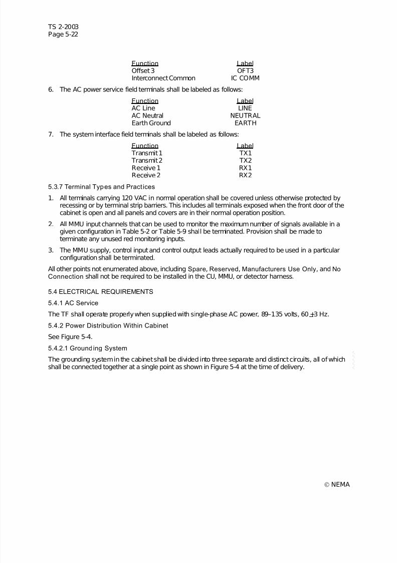
7/30/2019 NEMA TS2-2003- Traffic Controller Assemb
http://slidepdf.com/reader/full/nema-ts2-2003-traffic-controller-assemb 202/246
TS 2-2003Page 5-22
© NEMA
Function LabelOffset 3 OFT3Interconnect Common IC COMM
6. The AC power service field terminals shall be labeled as follows:
Function Label AC Line LINEAC Neutral NEUTRALEarth Ground EARTH
7. The system interface field terminals shall be labeled as follows:
Function Label Transmit 1 TX1 Transmit 2 TX2Receive 1 RX1Receive 2 RX2
5.3.7 Terminal Types and Pract ices
1. All terminals carrying 120 VAC in normal operation shall be covered unless otherwise protected byrecessing or by terminal strip barriers. This includes all terminals exposed when the front door of thecabinet is open and all panels and covers are in their normal operation position.
2. All MMU input channels that can be used to monitor the maximum number of signals available in agiven configuration in Table 5-2 or Table 5-9 shall be terminated. Provision shall be made toterminate any unused red monitoring inputs.
3. The MMU supply, control input and control output leads actually required to be used in a particularconfiguration shall be terminated.
All other points not enumerated above, including Spare, Reserved, Manufacturers Use Only, and NoConnection shall not be required to be installed in the CU, MMU, or detector harness.
5.4 ELECTRICAL REQUIREMENTS
5.4.1 AC Service
The TF shall operate properly when supplied with single-phase AC power, 89–135 volts, 60 +3 Hz.
5.4.2 Power Distribution Within Cabinet
See Figure 5-4.
5.4.2.1 Grounding System
The grounding system in the cabinet shall be divided into three separate and distinct circuits, all of whichshall be connected together at a single point as shown in Figure 5-4 at the time of delivery.
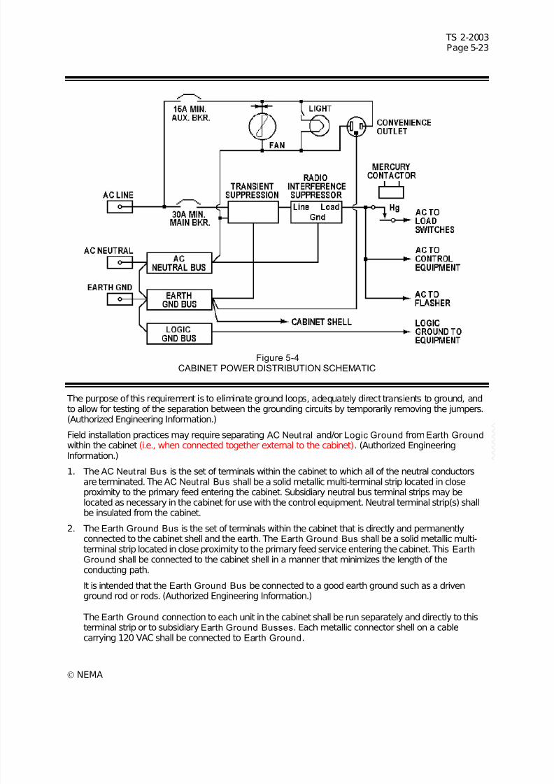
7/30/2019 NEMA TS2-2003- Traffic Controller Assemb
http://slidepdf.com/reader/full/nema-ts2-2003-traffic-controller-assemb 203/246
TS 2-2003Page 5-23
© NEMA
Figure 5-4CABINET POWER DISTRIBUTION SCHEMATIC
The purpose of this requirement is to eliminate ground loops, adequately direct transients to ground, and
to allow for testing of the separation between the grounding circuits by temporarily removing the jumpers.(Authorized Engineering Information.)
Field installation practices may require separating AC Neut ral and/or Logic Ground fromEarth Ground within the cabinet (i.e., when connected together external to the cabinet). (Authorized EngineeringInformation.)
1. The AC Neut ral Bus is the set of terminals within the cabinet to which all of the neutral conductorsare terminated. The AC Neut ral Bus shall be a solid metallic multi-terminal strip located in closeproximity to the primary feed entering the cabinet. Subsidiary neutral bus terminal strips may belocated as necessary in the cabinet for use with the control equipment. Neutral terminal strip(s) shallbe insulated from the cabinet.
2. The Earth Ground Bus is the set of terminals within the cabinet that is directly and permanentlyconnected to the cabinet shell and the earth. The Earth Ground Bus shall be a solid metallic multi-
terminal strip located in close proximity to the primary feed service entering the cabinet. This EarthGround shall be connected to the cabinet shell in a manner that minimizes the length of theconducting path.
It is intended that the Earth Ground Bus be connected to a good earth ground such as a drivenground rod or rods. (Authorized Engineering Information.)
The Earth Ground connection to each unit in the cabinet shall be run separately and directly to thisterminal strip or to subsidiary Earth Ground Busses. Each metallic connector shell on a cablecarrying 120 VAC shall be connected to Earth Ground.
7/30/2019 NEMA TS2-2003- Traffic Controller Assemb
http://slidepdf.com/reader/full/nema-ts2-2003-traffic-controller-assemb 204/246
TS 2-2003Page 5-24
© NEMA
3. The Logic Ground Bus is that set of Terminals within the cabinet to which all Logic Ground conductors are terminated.
All dc circuits shall use the Logic Ground as the return circuit.
5.4.2.2 Disconnecting Means
Type Poles Min. Amps Interrupting
Capacity Main 1 30 5,000 amperes
Auxiliary 1 15 5,000 amperes
The rating of the main disconnect means with overcurrent protection shall be not less than 125% of themaximum anticipated continuous load. All disconnecting means when used shall be the Trip-Indicating-Trip-Free type.
5.4.2.3 Signal Bus
The signal bus shall be connected to the incoming AC Line through a signal bus mercury contactor and aovercurrent protection device. The signal bus mercury contactor shall be energized to provide power tothe signal bus. The current rating of the signal bus mercury contactor shall be at least the current rating of
the main overcurrent protection device.
5.4.2.4 AC Service Transient Suppress ion
The transient suppression device for the primary feed of the cabinet shall be connected on the load sideof the cabinet overcurrent protection device as shown in Figure 5-4. The transient suppression deviceshall withstand a 20,000 ampere surge current with a 8x20 microsecond (time to crest x time to secondhalfcrest) waveform twenty times at 3-minute intervals between surges without damage or degradation tothe suppressor. Output voltage must not exceed 500 volts at any time during the test.
Because the severity of naturally occurring transients is highly variable AC service transient suppressionrequirements may vary with the application. For further information on transient protection of traffic controlequipment refer to NCHRP report 317. (Authorized Engineering Information.)
5.4.2.5 Radio Interference Suppression
Each cabinet shall be equipped with a radio interference suppressor installed at the input power point. Itshall provide a minimum attenuation of 50 decibels over a frequency range of from 200 kilohertz to 75megahertz, when used with normal installations.
The radio interference suppressor shall have a current rating equal to as a minimum the rating of themain disconnect means specified in 5.4.2.2 and be designed for operation on 120 volts, 60 hertz, singlephase circuits.
The ground connection of the radio interference suppressor shall be connected only to AC Neut ral andshall not be connected to Earth Ground directly.
5.4.2.6 Convenience Receptacle
A convenience receptacle shall be provided as part of the TF. The convenience receptacle shall be aduplex, three-prong, NEMA Type 5-15R grounding type outlet and shall have independent ground fault
circuit protection.
5.4.2.7 Lighting Fixture
An incandescent or fluorescent light shall be provided as part of the TF.
5.4.2.7.1 Fluorescent Fixture
The fluorescent lighting fixture shall be mounted on the inside top of the cabinet near the front edge. Thefixture shall be rated to accommodate a F15T8 lamp operated from a normal power factor UL or ETLlisted ballast (lamp not required to be provided).

7/30/2019 NEMA TS2-2003- Traffic Controller Assemb
http://slidepdf.com/reader/full/nema-ts2-2003-traffic-controller-assemb 205/246
TS 2-2003Page 5-25
© NEMA
5.4.2.7.2 Incandescent Fixture
The incandescent lamp receptacle shall be mounted on the inside top of the cabinet near the front edge. The receptacle shall be rated to accommodate a 100 watt medium base lamp (lamp not required to beprovided).
5.4.2.7.3 Lighting Fixture Switch The On-Off switch for the lighting fixture shall be either of the following:
1. A toggle switch mounted on an inside control panel, or
2. A door actuated switch that turns the light On when the door is open and Off when the door is closed.
5.4.3 Communications Transient Suppression
A transient suppressor shall be provided for the system interface communications lines when used. Thissuppressor shall withstand a 100 ampere 10x700 microsecond waveform 20 times at 30 second intervalsbetween surges without damage or degradation to the suppressor. The transient surge shall be appliedboth line to line and line to ground. Output voltage shall not exceed 8 volts line to line or 250 volts line toground at any time during the test.
Because the severity of naturally occurring transients is highly variable communications transientsuppression requirements may vary with the application. For further information on transient protection of traffic control equipment refer to NCHRP report 317. (Authorized Engineering Information.)
5.5 CONTROL CIRCUITS
5.5.1 Auto/Flash Switch
An Auto/Flash switch shall be accessible to an operator when the cabinet door is open. The switch shallbe rated by its manufacturer for the voltages and currents that may be expected to be present in the partof the control circuit where it is used.
The switch positions shall be labeled Auto and Flash. In the Auto position, this switch does not affect thenormal operation of the facilities. In the Flash position, the signal bus relay and flash transfer relays shallbe de-energized, connecting the output(s) of the flasher to the appropriate field leads and interrupting the
signal bus supply to the load switches.5.5.2 Flash Transfer Contro l
1. The coil of the flash transfer relay(s) shall be deenergized for flashing operation.
2. The flash transfer relay(s) shall be located in close proximity to the load switches, flasher, and signalfield terminals.
3. Flash transfer relay sockets shall mate with a Cinch-J ones P2408 or equivalent. They shall be wiredand space provided to accept a relay as described in 6.4, Flash Transfer Relays.
5.5.3 Malfunc tion Management Unit
1. Type Selection
The type select input to the MMU shall be connected to logic ground to select Type 16 (16 channel)operation.
2. Interlock
The facilities shall be so constructed that the intersection will revert to flashing operation if the MMU isdisconnected (see Figure 5-5).

7/30/2019 NEMA TS2-2003- Traffic Controller Assemb
http://slidepdf.com/reader/full/nema-ts2-2003-traffic-controller-assemb 206/246
TS 2-2003Page 5-26
© NEMA
3. Red Enable
The Red Enable input to the MMU shall be connected to the AC Line side of the signal bus relay coil(see Figure 5-5).
4. 24-Volt Monitoring
The MMU 24V Monitor I input shall be connected to the +24 volt feed to the load switches. The 24VMonitor II shall be used to monitor any other +24 volt supply(s) required for safe operation of theintersection.
If only one +24 volt power source is used in the cabinet, 24V Monitor I and II shall be connectedtogether.
5. Controller Voltage Monitor
When using a Type 1 CU the MMU Controller Voltage Monitor input shall be connected to the CUFault Monitor output.
If a Type 2 CU is used, connection to the MMU Controller Voltage Monitor input will depend on the
controller input/output mode. If mode 0 is used the MMU Controller Voltage Monitor input shall beconnected to the CU Controller Voltage Monitor output. For all other modes (1–7) the CU Faul tMonitor output shall be used.
6. Restart
Actuation of the Start-Delay shall remove power from the CU and power supply.
7. Stop Time
Stop Time shall be applied to all rings of the CU whenever the MMU is in the Fault condition (seeFigure 5-5).
8. Flash on Fault
The MMU shall place the intersection into flashing operation when in the Fault condition (see Figure5-5).
9. Load Switch Monitoring
Each of the MMU channels required for the application shall be wired to monitor the green, yellow,and red outputs of the associated load switch position in the TF as shown in Table 5-14.
Table 5-14MMU CHANNEL ASSIGNMENTS
MMU Channel Load Switch
Channel 1 Load Switch 1Channel 2 Load Switch 2Channel 3 Load Switch 3Channel 4 Load Switch 4Channel 5 Load Switch 5Channel 6 Load Switch 6Channel 7 Load Switch 7Channel 8 Load Switch 8Channel 9 Load Switch 9Channel 10 Load Switch 10Channel 11 Load Switch 11Channel 12 Load Switch 12
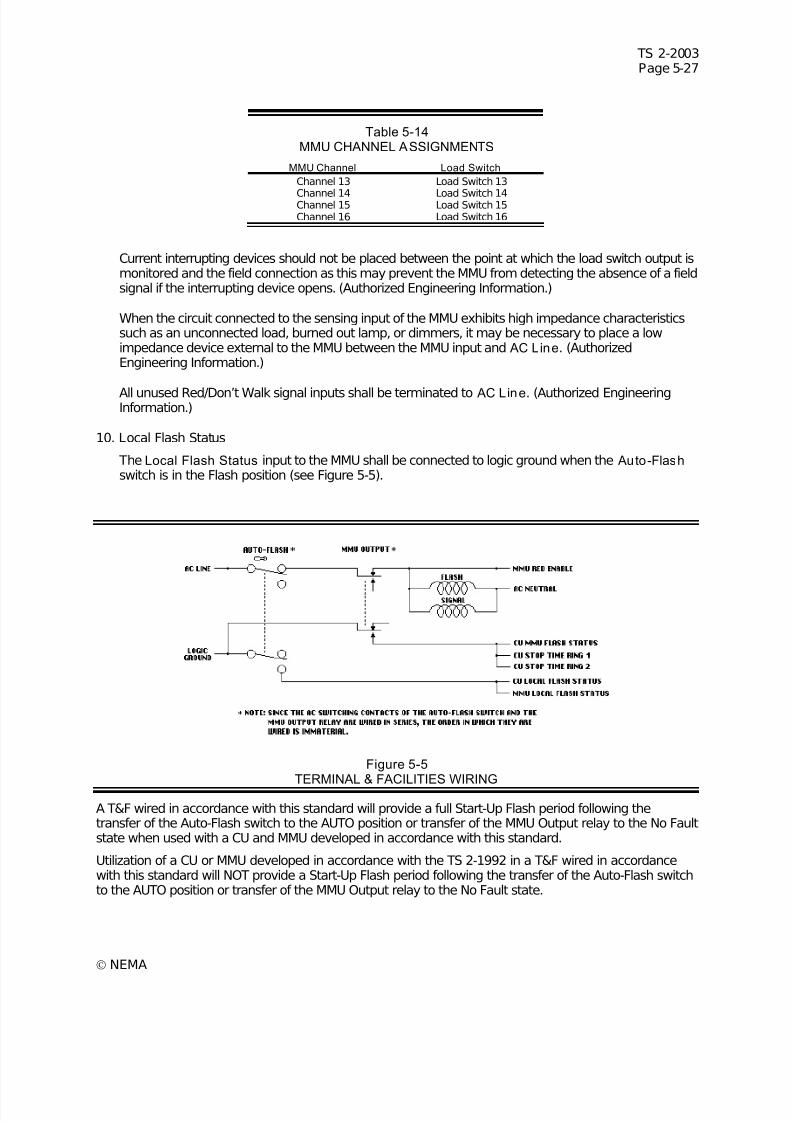
7/30/2019 NEMA TS2-2003- Traffic Controller Assemb
http://slidepdf.com/reader/full/nema-ts2-2003-traffic-controller-assemb 207/246
TS 2-2003Page 5-27
© NEMA
Table 5-14MMU CHANNEL ASSIGNMENTS
MMU Channel Load Switch
Channel 13 Load Switch 13
Channel 14 Load Switch 14Channel 15 Load Switch 15Channel 16 Load Switch 16
Current interrupting devices should not be placed between the point at which the load switch output ismonitored and the field connection as this may prevent the MMU from detecting the absence of a fieldsignal if the interrupting device opens. (Authorized Engineering Information.)
When the circuit connected to the sensing input of the MMU exhibits high impedance characteristicssuch as an unconnected load, burned out lamp, or dimmers, it may be necessary to place a lowimpedance device external to the MMU between the MMU input and AC Line. (AuthorizedEngineering Information.)
All unused Red/Don’t Walk signal inputs shall be terminated to AC Line. (Authorized EngineeringInformation.)
10. Local Flash Status
The Local Flash Status input to the MMU shall be connected to logic ground when the Auto-Flash switch is in the Flash position (see Figure 5-5).
Figure 5-5
TERMINAL & FACILITIES WIRING
A T&F wired in accordance with this standard will provide a full Start-Up Flash period following thetransfer of the Auto-Flash switch to the AUTO position or transfer of the MMU Output relay to the No Faultstate when used with a CU and MMU developed in accordance with this standard.
Utilization of a CU or MMU developed in accordance with the TS 2-1992 in a T&F wired in accordancewith this standard will NOT provide a Start-Up Flash period following the transfer of the Auto-Flash switchto the AUTO position or transfer of the MMU Output relay to the No Fault state.

7/30/2019 NEMA TS2-2003- Traffic Controller Assemb
http://slidepdf.com/reader/full/nema-ts2-2003-traffic-controller-assemb 208/246
TS 2-2003Page 5-28
© NEMA

7/30/2019 NEMA TS2-2003- Traffic Controller Assemb
http://slidepdf.com/reader/full/nema-ts2-2003-traffic-controller-assemb 209/246

7/30/2019 NEMA TS2-2003- Traffic Controller Assemb
http://slidepdf.com/reader/full/nema-ts2-2003-traffic-controller-assemb 210/246
7/30/2019 NEMA TS2-2003- Traffic Controller Assemb
http://slidepdf.com/reader/full/nema-ts2-2003-traffic-controller-assemb 211/246
TS 2-2003Page 6-1
© NEMA
SECTION 6 AUXILIARY DEVICES
This section defines the minimum requirements for auxiliary devices within the cabinet consisting of solidstate load switches, solid state flashers, flash transfer relays, and inductive loop detector units.
6.1 DEFINITIONS
(Reserved)
6.2 THREE-CIRCUIT SOLID STATE LOAD SWITCHES
This section defines the solid state load switches which are connected between the AC Line power andthe traffic signals. For the purpose of these standards, the term Solid State shall be construed to meanthat the main current to the signal load is not switched by electromechanical relay contacts.
6.2.1 Physical Characteristics
1. The overall dimensions of the switch shall not exceed 222.25 mm (8.75 in.) from the surface of theconnector, to the front of the unit including the handle or gripping device. The switch shall be no morethan 44.45 mm (1.75 in.) in width and no more than 106.68 mm (4.20 in.) in height.
2. The switch shall intermate with a Beau-Vernitron type socket S-5412 or Cinch-J ones socket S-2412SB, or equivalent.
3. The switch shall be so constructed that its lower surface will be no more than 53.34 mm (2.100 in.)below the centerline of the connector.
4. The switch shall be so constructed that no part of it will extend more than 22.86 mm (0.900 in.) to theleft and 27.94 mm (1.100 in.) to the right of the centerline of the connector as viewed from the front.See Figure 5-2.
5. Serviceable internal components of the load switch shall be readily accessible.
6. An enclosure suitably protected against corrosion shall be provided to enclose all electrical parts of the load switches.
7. The front panel of the load switch shall be provided with one indicator per input circuit to indicate thestate of each input circuit of the load switch. The indicators shall be mounted as follows whenoriented as normally mounted:
Circuit A at the top.Circuit B in the middle.Circuit C at the bottom.
8. Material and Construction of Rigid Printed Circuit Assemblies
a. Materials
All printed circuit boards shall be made from NEMA (FR-4) glass-epoxy, flame retardant material,or equivalent. (See NEMA Standards Publication LI-1-1989, Industrial Laminated ThermosettingProducts.) Circuit boards exceeding 50.8 mm (2 in.) in any dimension shall be at least 1.58 mm(1/16 in.) nominal thickness. Circuit boards not exceeding 50.8 mm (2 in.) in any dimension shallbe at least 0.79 mm (1/32 in.) nominal thickness.
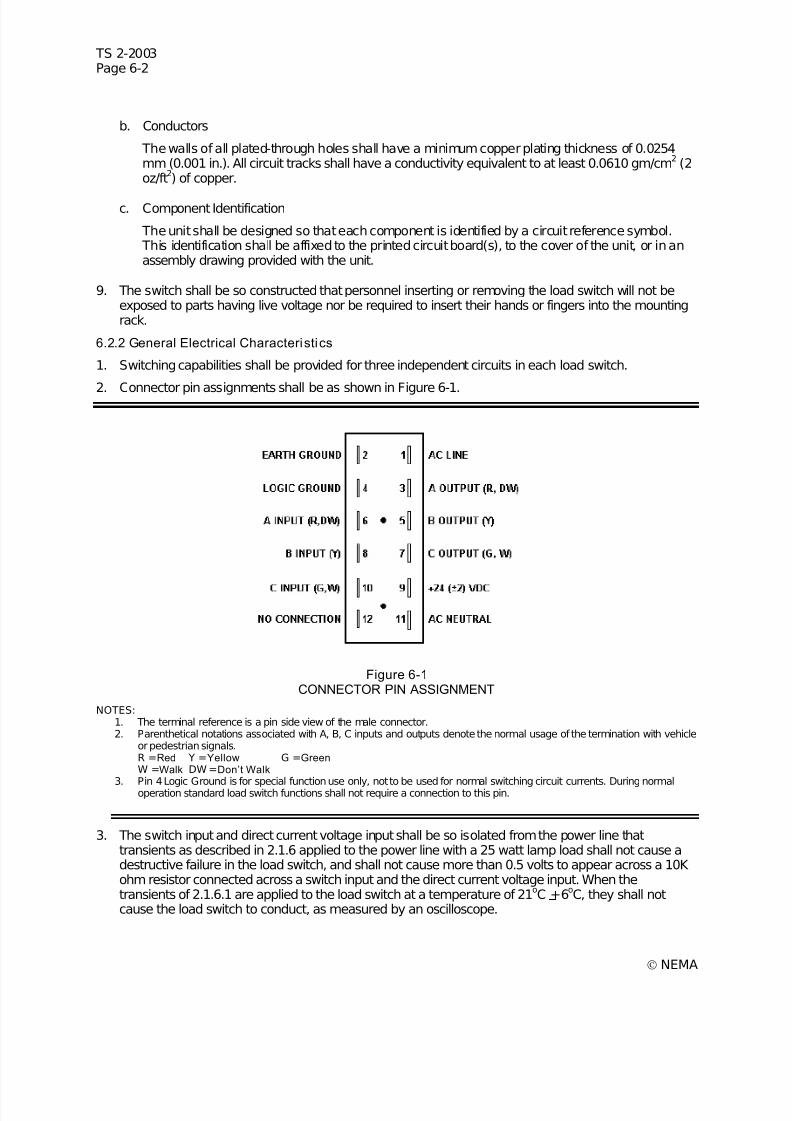
7/30/2019 NEMA TS2-2003- Traffic Controller Assemb
http://slidepdf.com/reader/full/nema-ts2-2003-traffic-controller-assemb 212/246
TS 2-2003Page 6-2
© NEMA
b. Conductors
The walls of all plated-through holes shall have a minimum copper plating thickness of 0.0254mm (0.001 in.). All circuit tracks shall have a conductivity equivalent to at least 0.0610 gm/cm
2(2
oz/ft2) of copper.
c. Component Identification
The unit shall be designed so that each component is identified by a circuit reference symbol. This identification shall be affixed to the printed circuit board(s), to the cover of the unit, or in anassembly drawing provided with the unit.
9. The switch shall be so constructed that personnel inserting or removing the load switch will not beexposed to parts having live voltage nor be required to insert their hands or fingers into the mountingrack.
6.2.2 General Electrical Characteristics
1. Switching capabilities shall be provided for three independent circuits in each load switch.
2. Connector pin assignments shall be as shown in Figure 6-1.
Figure 6-1CONNECTOR PIN ASSIGNMENT
NOTES:1. The terminal reference is a pin side view of the male connector.2. Parenthetical notations associated with A, B, C inputs and outputs denote the normal usage of the termination with vehicle
or pedestrian signals.R =Red Y =Yellow G =Green W =Walk DW =Don’t Walk
3. Pin 4 Logic Ground is for special function use only, not to be used for normal switching circuit currents. During normaloperation standard load switch functions shall not require a connection to this pin.
3. The switch input and direct current voltage input shall be so isolated from the power line thattransients as described in 2.1.6 applied to the power line with a 25 watt lamp load shall not cause adestructive failure in the load switch, and shall not cause more than 0.5 volts to appear across a 10K ohm resistor connected across a switch input and the direct current voltage input. When thetransients of 2.1.6.1 are applied to the load switch at a temperature of 21
oC +6
oC, they shall not
cause the load switch to conduct, as measured by an oscilloscope.
7/30/2019 NEMA TS2-2003- Traffic Controller Assemb
http://slidepdf.com/reader/full/nema-ts2-2003-traffic-controller-assemb 213/246
TS 2-2003Page 6-3
© NEMA
4. The switch shall turnOn within 10 degrees of the zero voltage point of the AC Line sinusoid on thefirst turn-on cycle. All subsequent cycles shall turn On within 5 degrees of the zero voltage point of the AC line sinusoid. The switch shall turn On within one half cycle following the application of theinput signal. The switch shall turn Off within 5 degrees of the zero current point of the AC linesinusoid and within one half cycle following the removal of the input signal.
5. Each load switch shall have electrical isolation between all inputs (pins 6, 8, 9, and 10) and all outputs(pins 1, 3, 5, and 7) of at least 2000 volts DC and at least 100 megohms resistive.
6. Logic Ground shall not be connected to either Earth Ground or AC Neut ral within the unit.
7. Earth Ground shall not be connected to either Logic Ground or AC Neut ral within the unit.
8. All metal portions of the enclosure including the handle of the load switches shall be connected toEarth Ground within the unit.
9. The load switch shall perform all of its defined functions when supplied from a 24 + 2 volt DC source.
6.2.3 Input Electrical Characteristics
1. All inputs shall be negative true logic which is referenced to the common of the +24 volt DC supplyand which is characterized by the following:
a. The transition zone of the input circuitry from the conducting state to the non-conducting state(and vice versa) shall occur between 6 and 16 volts.
b. A voltage between 0 and 6 volts shall cause the output device to conduct.
c. A voltage greater than 16 volts shall cause the output device not to conduct.
2. In absence of an input signal, the voltage at the input shall rise to the level of the +24 VDC supplywhen the input is connected to this supply through an external 10 K ohm pull-up resistor.
3. The load switch shall not draw more than 20 milliamperes from a +26 VDC supply unless more thanone circuit is energized in which case it shall not draw more than 20 milliamperes times the number of circuits energized.
4. Each input circuit of the load switch shall have reverse polarity protection.
6.2.4 Output Electrical Characteristics
1. The output current from the load switch through a 1200 watt load when the load switch is in the OFFstate shall not exceed 10 milliamperes peak at 135 volts RMS AC.
2. Each load switch output shall have a peak stand-off voltage of 500 volts or greater.
3. Each load switch output shall have a dv/dt rating of at least 100 volts per microsecond whenmeasured at 21
oC using the circuit in Figure 2-3.
4. Each switching circuit shall have a minimum rating of 10 amperes RMS for either a tungsten lampload or power factor corrected gas tubing transformer loads (power factor greater than 0.8) over avoltage range of 89 to 135 volts RMS AC at 60 hertz. Additionally, each load switch shall be capableof switching currents as low as 100 milliamperes. The load switch shall be rated for 10 amperescontinuous load divided between the circuits in any proportion, and additionally each circuit shall be
capable of continuously conducting 10 amperes. These ratings shall be for operation in still air whenthe load switch is oriented as normally mounted.
5. Each load switch circuit shall be designed to switch a 1200 watt tungsten lamp load operating from a120 volts RMS AC source for a minimum of 10 million operations.
6. Each load switch circuit shall be capable of withstanding a one second surge current of 40 amperesRMS (56.6 peak) at 60 hertz.
7. Each load switch circuit shall be capable of withstanding a one cycle surge current of 175 amperesRMS (247.5 peak) at 60 hertz while operating from a 120 volts RMS AC source.
7/30/2019 NEMA TS2-2003- Traffic Controller Assemb
http://slidepdf.com/reader/full/nema-ts2-2003-traffic-controller-assemb 214/246
TS 2-2003Page 6-4
© NEMA
6.3 SOLID STATE FLASHERS
This section defines solid state flashers which are used to periodically interrupt a source of AC line powerfor the purpose of providing flashing traffic signals. For the purpose of these standards, the termSolidState shall be construed to mean that the main current to the signal load is not switched by electro-mechanical operated contacts.
6.3.1 Type of Flasher
Dual circuit, 15 amperes RMS per circuit.
6.3.2 Physical Characteristics
1. The overall dimensions of the flasher shall not exceed 222.25 mm (8.75 in.) from the front panelsurface holding the mating connector, including the any handle or gripping device. The flasher shallbe no more than 48.26 mm (1.9 in.) in width and no more than 106.68 mm (4.2 in.) high.
2. The flasher shall intermate with a Beau-Vernitron socket type S-5406 or Cinch-J ones socket S-406-SB, or equivalent.
3. The flasher shall be so constructed that its lower surface will be no more than 53.34 mm (2.100 in.)below the center line of the connector configuration.
4. The flasher shall be so constructed that no part of it will extend more than 22.86 mm (0.900 in.) to theleft and 27.94 mm (1.100 in.) to the right of the centerline of the connector pin configuration as viewedfrom the front. See Figure 5-3.
5. Serviceable internal components of the flasher shall be readily accessible.
6. The flasher shall be so constructed that personnel inserting or removing the module will not beexposed to any part having live voltage nor be required to insert either their hands or fingers into theload rack.
7. An enclosure suitably protected against corrosion shall be provided to enclose all electrical parts of the flasher.
8. Material and Construction of Rigid Printed Circuit Assemblies
a. MaterialsAll printed circuit boards shall be made from NEMA (FR-4) glass-epoxy, or equivalent (see NEMAStandards Publication LI 1-1989, Industrial Laminated Thermosetting Products). Circuits boardsexceeding 50.8 mm (2 in.) in any dimension shall be at least 1.59 mm (0.063 in.) nominalthickness. Circuit boards not exceeding 50.8 mm (2 in.) in any dimension shall be at least 0.79mm (0.031 in.) nominal thickness.
b. Conductors
The walls of all plated through holes shall have a minimum copper plating thickness of 0.0254mm (0.001 in.). All circuit tracks shall have a conductivity equivalent to at least 0.0610 gm/cm
2(2
oz/ft2) of copper. All electrical mating surfaces shall be made of non-corrosive material.
c. Component Identification The unit shall be designed so that each component is identified by circuit reference symbol. Thisidentification may be affixed to the printed circuit board(s), the cover of the unit, or in an assemblydrawing provided with the unit.
9. All metal portions of the enclosure including the handle of the load switches shall be connected toEarth Ground within the unit.
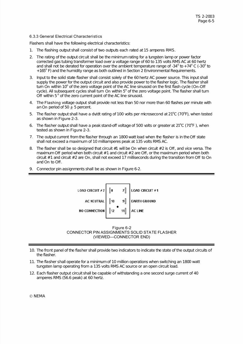
7/30/2019 NEMA TS2-2003- Traffic Controller Assemb
http://slidepdf.com/reader/full/nema-ts2-2003-traffic-controller-assemb 215/246
TS 2-2003Page 6-5
© NEMA
6.3.3 General Electrical Characteristics
Flashers shall have the following electrical characteristics:
1. The flashing output shall consist of two outputs each rated at 15 amperes RMS.
2. The rating of the output circuit shall be the minimum rating for a tungsten lamp or power factorcorrected gas tubing transformer load over a voltage range of 60 to 135 volts RMS AC at 60 hertzand shall not be derated for operation over the ambient temperature range of -34
oto +74
oC (-30
oto
+165o
F) and the humidity range as both outlined in Section 2 Environmental Requirements.
3. Input to the solid state flasher shall consist solely of the 60 hertz AC power source. This input shallsupply the power for the output circuit and also provide power to the flasher logic. The flasher shallturn On within 10o of the zero voltage point of the AC line sinusoid on the first flash cycle (On-Off cycle). All subsequent cycles shall turn On within 5o of the zero voltage point. The flasher shall turnOff within 5
oof the zero current point of the AC line sinusoid.
4. The Flashing voltage output shall provide not less than 50 nor more than 60 flashes per minute withanOn period of 50 + 5 percent.
5. The flasher output shall have a dv/dt rating of 100 volts per microsecond at 21oC (70oF), when tested
as shown in Figure 2-3.6. The flasher output shall have a peak stand-off voltage of 500 volts or greater at 21
oC (70
oF ), when
tested as shown in Figure 2-3.
7. The output current from the flasher through an 1800 watt load when the flasher is in the Off stateshall not exceed a maximum of 10 milliamperes peak at 135 volts RMS AC.
8. The flasher shall be so designed that circuit #1 will be On when circuit #2 is Off , and vice versa. ThemaximumOff period when both circuit #1 and circuit #2 are Off , or the maximum period when bothcircuit #1 and circuit #2 are On, shall not exceed 17 milliseconds during the transition fromOff to On and On to Off .
9. Connector pin assignments shall be as shown in Figure 6-2.
Figure 6-2CONNECTOR PIN ASSIGNMENTS SOLID STATE FLASHER
(VIEWED—CONNECTOR END)
10. The front panel of the flasher shall provide two indicators to indicate the state of the output circuits of the flasher.
11. The flasher shall operate for a minimum of 10 million operations when switching an 1800 watttungsten lamp operating from a 135 volts RMS AC source or an open circuit load.
12. Each flasher output circuit shall be capable of withstanding a one second surge current of 40amperes RMS (56.6 peak) at 60 hertz.
7/30/2019 NEMA TS2-2003- Traffic Controller Assemb
http://slidepdf.com/reader/full/nema-ts2-2003-traffic-controller-assemb 216/246
TS 2-2003Page 6-6
© NEMA
13. Each flasher output circuit shall be capable of withstanding a one cycle surge current of 175 amperesRMS (247.5 peak) at 60 hertz.
6.4 FLASH TRANSFER RELAYS
These standards define the minimum requirements for an interchangeable electromechanical flashtransfer relay. This relay is intended to be used for transferring traffic signal circuits from the outputs of the load switches to the output(s) of a flasher.
6.4.1 Environmental Requirements
6.4.1.1 Temperature and Humidi ty
The relay shall maintain all of its defined functions over the temperature and humidity range of 2.1.5.Neither the protective case nor any other part shall deform when the relay is operated under full load atmaximum temperature with 135 VAC continuously applied to the coil.
6.4.1.2 Vibration and Shock
The relay shall operate and maintain its physical integrity when subjected to the vibration and shockrequirements of 2.1.9 and 2.1.10.
The relay contacts may momentarily change state when subjected to the vibration and shock definedabove. (Authorized Engineering Information.)
6.4.1.3 Transients
The relay shall be capable of withstanding the high energy transient requirements of 2.1.8.
6.4.2 Mechanical Requirements
6.4.2.1 Enclosure
All electrical parts of the relay shall be enclosed in a transparent plastic case. This case shall protect therelay from dust, moisture, and other contamination. It shall be constructed so that the contacts and coilassembly may be viewed through the sides of the case. It shall be sufficiently rugged to permit the relayto be inserted and removed from its mating socket using the case as a handle.
6.4.2.2 Contacts And Connector
The relay shall be provided with two single-pole, double-throw (form C) contacts and mount on an eightpin spade plug base wired as shown in Figure 6-3. The spade plug base shall mate with a Cinch-J ones2408SB socket or equivalent.
6.4.2.3 Dimensions
The relay shall not exceed the physical dimensions shown in Figure 6-3.
6.4.3 Electrical Requirements
6.4.3.1 Contact Rating
The contact points and contact arms shall be capable of operating for 30,000 cycles with 10 amperes of tungsten load per contact at 120 VAC.
6.4.3.2 Contact Material
Contact points shall be of fine silver, silver-alloy, or superior alternative material.
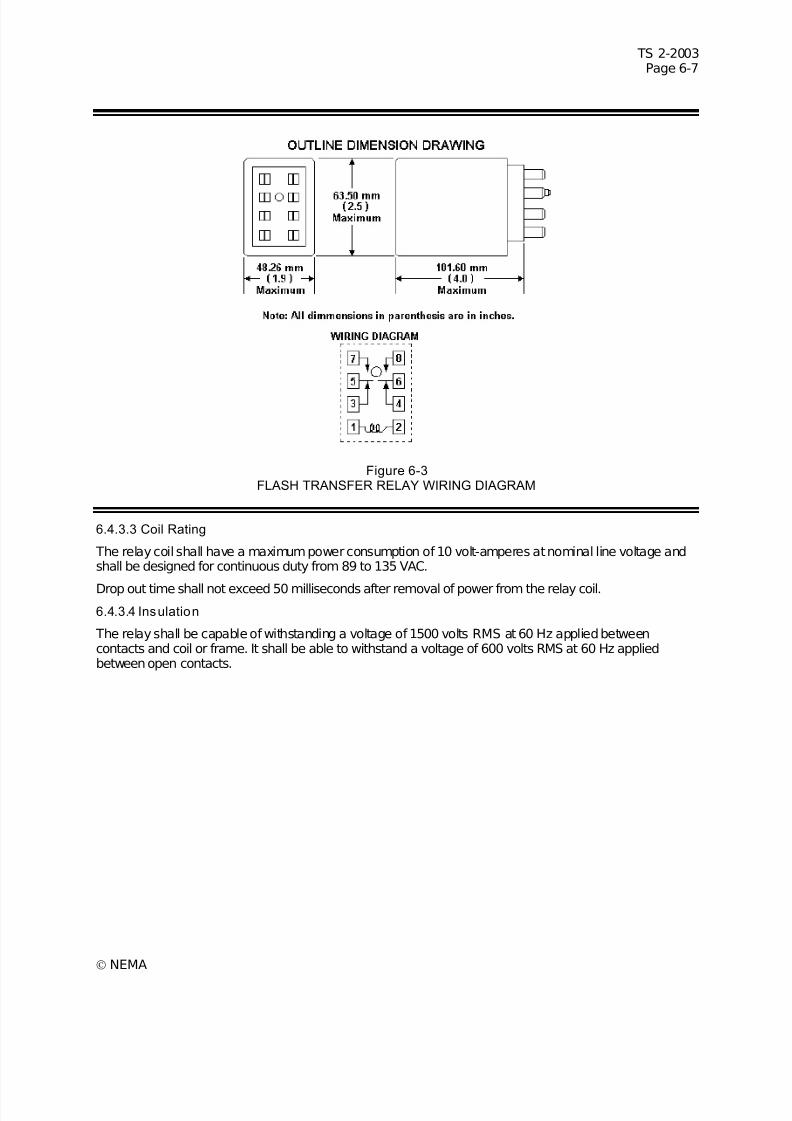
7/30/2019 NEMA TS2-2003- Traffic Controller Assemb
http://slidepdf.com/reader/full/nema-ts2-2003-traffic-controller-assemb 217/246
TS 2-2003Page 6-7
© NEMA
Figure 6-3FLASH TRANSFER RELAY WIRING DIAGRAM
6.4.3.3 Coil Rating
The relay coil shall have a maximum power consumption of 10 volt-amperes at nominal line voltage andshall be designed for continuous duty from 89 to 135 VAC.
Drop out time shall not exceed 50 milliseconds after removal of power from the relay coil.
6.4.3.4 Insulation
The relay shall be capable of withstanding a voltage of 1500 volts RMS at 60 Hz applied betweencontacts and coil or frame. It shall be able to withstand a voltage of 600 volts RMS at 60 Hz appliedbetween open contacts.
7/30/2019 NEMA TS2-2003- Traffic Controller Assemb
http://slidepdf.com/reader/full/nema-ts2-2003-traffic-controller-assemb 218/246
TS 2-2003Page 6-8
© NEMA
6.5 INDUCTIVE LOOP DETECTOR UNITS
Clause 6.5 responds to the need for a series of Inductive Loop Detector Units which provide inputs fortraffic-actuated or traffic-responsive control, surveillance, or data collection systems. The Inductive LoopDetector Unit responds to the presence of vehicles on the roadway by relying upon the effect of theconductive mass of the vehicle on the alternating magnetic field of a loop. When a vehicle passes overthe loop of wire embedded in the surface of the roadway, it reacts with the alternating magnetic fieldwhich is associated with that loop. On standard loops this reaction is a reduction in loop inductance.
These standards cover the performance and design requirements of interchangeable Inductive LoopDetector Units. A Detector Unit used with a sensor loop embedded in the surface of a roadway detectsvehicles moving or standing in the detection zone of the sensor loop. The output of the Detector Unit maybe used directly to provide an input to a vehicle-actuated traffic CU or provide inputs to traffic-responsivecontrol and surveillance systems. Detector Units generate outputs indicative of vehicles passing throughthe sensor loop zone of detection. This output may be used for counting (volume) or for detectingpresence time representative of the time that vehicles are in the sensor loop zone of detection(occupancy), or both. When two loops are placed in a lane, one downstream from the other, the timebetween the sequential responses of detectors attached to these loops may be used to measure speed.
6.5.1 Loop Detector Unit Definitions
6.5.1.1 Channel
Electronic circuitry which functions as a Loop Detector System.
6.5.1.2 Crosstalk
The adverse interaction of any channel of a Detector Unit with any other channel.
6.5.1.3 Detector Mode
A term used to describe the duration and conditions of the occurrence of a detector output.
6.5.1.4 Lead-In Cable
The electrical cable which serves to connect the sensor loop(s) to the input of the Detector Unit.
6.5.1.5 Loop Detector System
A vehicle detector system that senses a decrease in inductance of its sensor loop(s) during the passageor presence of a vehicle in the zone of detection of the sensor loop(s).
6.5.1.6 Loop Detector Unit
An electronic device which is capable of energizing the sensor loop(s), of monitoring the sensor loop(s)inductance, and of responding to a predetermined decrease in inductance with output(s) which indicatesthe passage or presence of vehicles in the zone(s) of detection.
6.5.1.7 Reset Channel
A command for the Detector Unit to calculate a new reference frequency (the frequency that the looposcillates at when no vehicle is influencing the loop) for the channel being reset and to appropriately
adjust other channel related parameters.6.5.1.8 Reset Uni t
A command for the Detector Unit to set all parameters to the states they would be set at if power hadbeen applied at the moment the RESET command is received or released.
6.5.1.9 Sensor Loop
An electrical conductor arranged to encompass a portion of roadway to provide a zone of detection anddesigned such that the passage or presence of a vehicle in the zone causes a decrease in the inductanceof the loop that can be sensed for detection purposes.
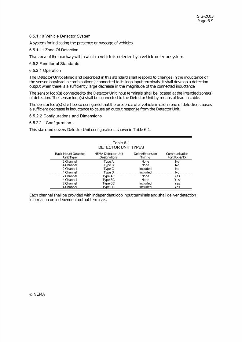
7/30/2019 NEMA TS2-2003- Traffic Controller Assemb
http://slidepdf.com/reader/full/nema-ts2-2003-traffic-controller-assemb 219/246
TS 2-2003Page 6-9
© NEMA
6.5.1.10 Vehicle Detector System
A system for indicating the presence or passage of vehicles.
6.5.1.11 Zone Of Detection
That area of the roadway within which a vehicle is detected by a vehicle detector system.
6.5.2 Functional Standards
6.5.2.1 Operation
The Detector Unit defined and described in this standard shall respond to changes in the inductance of the sensor loop/lead-in combination(s) connected to its loop input terminals. It shall develop a detectionoutput when there is a sufficiently large decrease in the magnitude of the connected inductance.
The sensor loop(s) connected to the Detector Unit input terminals shall be located at the intended zone(s)of detection. The sensor loop(s) shall be connected to the Detector Unit by means of lead-in cable.
The sensor loop(s) shall be so configured that the presence of a vehicle in each zone of detection causesa sufficient decrease in inductance to cause an output response from the Detector Unit.
6.5.2.2 Configurations and Dimensions
6.5.2.2.1 Configurations
This standard covers Detector Unit configurations shown in Table 6-1.
Table 6-1DETECTOR UNIT TYPES
Rack Mount DetectorUnit Type
NEMA Detector UnitDesignations
Delay/Extension Timing
CommunicationPort RX & TX
2 Channel Type A None No4 Channel Type B None No2 Channel Type C Included No4 Channel Type D Included No2 Channel Type AC None Yes
4 Channel Type BC None Yes2 Channel Type CC Included Yes4 Channel Type DC Included Yes
Each channel shall be provided with independent loop input terminals and shall deliver detectioninformation on independent output terminals.
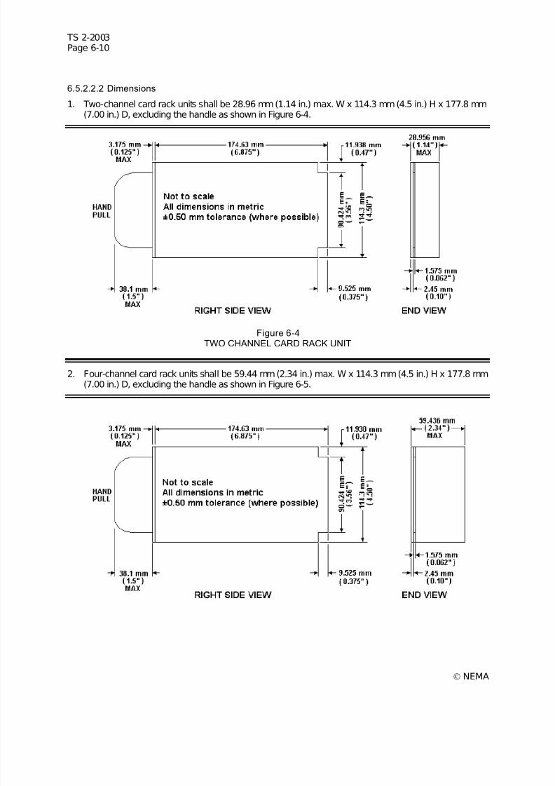
7/30/2019 NEMA TS2-2003- Traffic Controller Assemb
http://slidepdf.com/reader/full/nema-ts2-2003-traffic-controller-assemb 220/246
TS 2-2003Page 6-10
© NEMA
6.5.2.2.2 Dimensions
1. Two-channel card rack units shall be 28.96 mm (1.14 in.) max. W x 114.3 mm (4.5 in.) H x 177.8 mm(7.00 in.) D, excluding the handle as shown in Figure 6-4.
Figure 6-4TWO CHANNEL CARD RACK UNIT
2. Four-channel card rack units shall be 59.44 mm (2.34 in.) max. W x 114.3 mm (4.5 in.) H x 177.8 mm(7.00 in.) D, excluding the handle as shown in Figure 6-5.

7/30/2019 NEMA TS2-2003- Traffic Controller Assemb
http://slidepdf.com/reader/full/nema-ts2-2003-traffic-controller-assemb 221/246
TS 2-2003Page 6-11
© NEMA
Figure 6-5FOUR CHANNEL CARD RACK UNIT
6.5.2.3 Accessibility
The Detector Unit shall be easily disassembled to gain access for maintenance. When thusdisassembled, the Detector Unit shall be operational for trouble shooting.
6.5.2.4 Material and Construction of Rigid Printed Circuit Assemblies
6.5.2.4.1 Materials
All printed circuit boards shall be per 3.2.3.1.
6.5.2.4.2 Component Identif ication
All components shall be identified per 3.2.3.3.
6.5.2.5 Power Inputs
6.5.2.5.1 Detector Unit DC Supply Voltage
1. Voltage Range–The voltage range shall be 10.8 VDC minimum to 26.5 VDC maximum.
2. Ripple–The maximum supply ripple shall be 500 millivolts peak to peak.
This input supplies power. The current consumption shall not exceed 50 milliamperes per channel. Thereturn for this input is Logic Ground as described in 6.5.2.6. This input shall not be connected within theunit to any loop input. The input shall draw a surge current not to exceed 5 amps at the time of powerapplication to the input. The Detector Unit shall not be damaged by insertion to or removal from apowered Detector Rack.
6.5.2.5.2 Low Supply Voltage Automatic Reset
A Reset Unit condition shall be activated anytime the input DC supply voltage falls below that which isrequired for operation, as defined in this standard.
A Reset Unit condition shall not be activated when the DC Supply Input falls below 10 volts for less than0.25 milliseconds.
6.5.2.6 Logic Ground
This input is the return for the Detector Unit DC Supply input. This point shall not be connected within theunit to AC Neut ral , Earth Ground, or to any loop input terminal.
6.5.2.7 Earth Ground
The loop Detector Unit shall have a terminal for connection to the chassis of the unit. This input shall notbe connected to Logic Ground, AC Neut ral , or to any other point within the unit, except that it shall bepermissible to use this input as a return for transient protection devices.
If the unit has a metallic case or front panel, the case and/or front panel shall be connected to EarthGround.
6.5.2.8 DC Control Inputs
Control inputs shall have the following characteristics as measured from Logic Ground.
6.5.2.8.1 Low or Active State
A voltage between 0 and 8 volts shall be considered the Low or active state.
6.5.2.8.2 High or Inactive State
A voltage greater than 16 volts shall be considered the High or inactive state.
7/30/2019 NEMA TS2-2003- Traffic Controller Assemb
http://slidepdf.com/reader/full/nema-ts2-2003-traffic-controller-assemb 222/246
TS 2-2003Page 6-12
© NEMA
6.5.2.8.3 Transition Voltage Zone Of Input Circui try
Transition zone of input circuitry fromLow state to High state and vice versa shall occur between 8 and16 volts.
6.5.2.8.4 External Transition Time
External transition fromLow state to High state and vice versa shall be accomplished within 0.1milliseconds.
6.5.2.8.5 Maximum Current
Over the voltage range 0 to 26 volts DC, the maximum current In orOut of any input control terminal shallbe less than 10 milliamperes. The input circuitry shall be returned to the Detector Unit DC supply in sucha manner that the removal of all connections to the input shall allow the voltage at the input terminal torise to the High or inactive state. Rising to Detector Unit DC supply voltage is permitted.
6.5.2.8.6 Signal Recogn ition
Any input signal (including External Reset, Pin C) shall respond as defined in 3.3.5.1.3.
All channels shall remain in a RESET UNIT or RESET CHANNEL condition, see 6.5.1.7 and 6.5.1.8,
while Pin C is held in an Active State (Low) voltage.6.5.2.8.7 Activation of Delay/Extension Feature
The application of a Low state voltage to a Delay/Extension input shall function to inhibit the delay timingfunction and/or enable the extend timing function.
This input is provided for downward compatibility. (Authorized Engineering Information.)
6.5.2.8.8 Acti vation of Detector Unit Address Feature
The application of a Low state voltage to a Detector Unit Address input shall activate the input, e.g. it isa logic 1. Four address input pins shall provide for a maximum of 15 hard wired addresses. AddressFF(hex) shall be a broadcast address.
6.5.2.9 Data Receive (RX) Input
The Data Receive input, RX, must have an input impedance 45 Kohm to 105 Kohm and an inputcapacitance less than 250 picofarads. This input impedance shall terminate to DC common. The inputopen circuit voltage shall be less than 0.9 VDC. The input shall be functional when voltages over the rangeof ±25 VDC are applied to it. The Transition Region is any voltage between a Mark and a Space.
6.5.2.9.1 Mark State (Binary 1)
During Mark, the RX input shall recognize as a Mark voltages less than 0.9 VDC.
6.5.2.9.2 Space State (Binary 0)
During Space, the RX input shall recognize as a Space voltages greater than 3.0 VDC.
6.5.2.9.3 Other States
The RX input shall not be damaged when connected to any voltage up to 26 VDC and:
1. Shall rise to >8.5 VDC when connected to +12 VDC through 30 Kohm.
2. Shall rise to >16 VDC when connected to +22 VDC through 11 Kohm.
6.5.2.9.4 Transient Withstand
The RX input shall not be damaged by application of the transients described in 2.1.7.1 through 2.1.7.5.
7/30/2019 NEMA TS2-2003- Traffic Controller Assemb
http://slidepdf.com/reader/full/nema-ts2-2003-traffic-controller-assemb 223/246
TS 2-2003Page 6-13
© NEMA
6.5.2.10 Loop Inputs
Two loop input terminals shall be provided for each sensor channel. These inputs shall be isolated(resistance >106 and breakdown voltage >1000 VRMS) fromLogic Ground, AC Neut ral , and the controlinput and output circuits.
6.5.2.11 Loop/Lead in Electrical PropertiesEach channel of the Detector Unit shall function in accordance with the specific requirements of thisstandard and in addition shall operate without significant degradation with any sensor loop/lead-incombination which exhibits the following electrical properties as measured at the Detector Unit terminalsof the lead-in:
1. Inductance at 50 KHz – 50 to 1000 microhenries.
2. Q at 50 KHz–greater than 5.
3. Resistance to earth ground–greater than 1 megohm.
4. Field installation practices or Detector Unit design may require grounding the shield of the loop lead-in cable. Such grounding should be in accordance with the Detector Unit manufacturer'srecommendation.
6.5.2.12 Test Loop Configurations
Sensor loop and lead-in combinations used to verify the performance requirements of this standard shallconsist of the following combinations of 1.828 m x 1.828 m (6 ft. x 6 ft) three-turn loops and shielded lead-in cable as illustrated in Figure 6-6.
1. Single-loop 1.828 m x 1.828 m (6 ft. by 6 ft.), three turns, with 30.48 m (100 ft.) of lead-in (80–105microhenries).
2. Single-loop 1.828 m x 1.828 m (6 ft. by 6 ft.), three turns, with 304.8 m (1,000 ft.) of lead-in (260–320microhenries).
3. Four loops 1.828 m x 1.828 m (6 ft. by 6 ft.), three turns, in a row in the direction of travel andseparated by 2.743 m (9 feet), series/parallel connected with 76.0 m (250 ft.) of lead-in (100–140microhenries).
6.5.2.13 Test Vehicle Definiti on
Detector Units shall detect all vehicles which ordinarily traverse the public streets and highways andwhich are comprised of sufficient conductive material suitably located to permit recognition and responseby the Detector System.
Vehicles are classified by this standard in accordance with the reduction in inductance resulting whenthey are centered in the single 1.828 m x 1.828 m (6 ft. x 6 ft.), three-turn-test loop with 30.48 (100 feet)of lead-in.
These minimum reductions are as follows:
1. Class 1: 0.13 percent (dL/L) or 0.12 microhenries (dL) inductance change with a single 1.83 m x 1.83m (6 ft x 6 ft), three turn loop, with 30.48 m (100 ft) lead-in (small motorcycle).
2. Class 2: 0.32 percent (dL/L) or 0.3 microhenries (dL) inductance change with a single 1.83 m x 1.83m (6 ft x 6 ft), three turn loop, with 30.48 m (100 ft) lead-in (large motorcycle).
3. Class 3: 3.2 percent (dL/L) or 3.0 microhenries (dL) inductance change with a single 1.83 m x 1.83 m(6 ft x 6 ft), three turn loop, with 30.48 m (100 ft) lead-in (automobile).
The maximum reduction caused by a class three vehicle shall be 5.4 percent (dL/L) or 5 microhenries(dL) inductance change with a single 1.83 m x 1.83 m (6 ft x 6 ft), three-turn loop with 30.48 m (100 ft)lead-in.
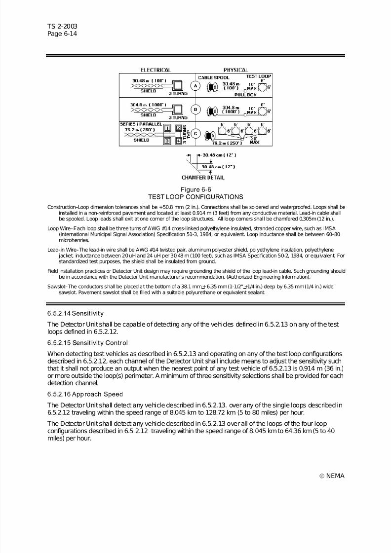
7/30/2019 NEMA TS2-2003- Traffic Controller Assemb
http://slidepdf.com/reader/full/nema-ts2-2003-traffic-controller-assemb 224/246
TS 2-2003Page 6-14
© NEMA
Figure 6-6TEST LOOP CONFIGURATIONS
Construction–Loop dimension tolerances shall be +50.8 mm (2 in.). Connections shall be soldered and waterproofed. Loops shall beinstalled in a non-reinforced pavement and located at least 0.914 m (3 feet) from any conductive material. Lead-in cable shallbe spooled. Loop leads shall exit at one corner of the loop structures. All loop corners shall be chamfered 0.305m (12 in.).
Loop Wire–Each loop shall be three turns of AWG #14 cross-linked polyethylene insulated, stranded copper wire, such as IMSA(International Municipal Signal Association) Specification 51-3, 1984, or equivalent. Loop inductance shall be between 60–80microhenries.
Lead-in Wire–The lead-in wire shall be AWG #14 twisted pair, aluminum polyester shield, polyethylene insulation, polyethylene jacket, inductance between 20 uH and 24 uH per 30.48 m (100 feet), such as IMSA Specification 50-2, 1984, or equivalent. Forstandardized test purposes, the shield shall be insulated from ground.
Field installation practices or Detector Unit design may require grounding the shield of the loop lead-in cable. Such grounding shouldbe in accordance with the Detector Unit manufacturer’s recommendation. (Authorized Engineering Information).
Sawslot–The conductors shall be placed at the bottom of a 38.1 mm +6.35 mm (1-1/2" +1/4 in.) deep by 6.35 mm (1/4 in.) widesawslot. Pavement sawslot shall be filled with a suitable polyurethane or equivalent sealant.
6.5.2.14 Sensit ivit y
The Detector Unit shall be capable of detecting any of the vehicles defined in 6.5.2.13 on any of the testloops defined in 6.5.2.12.
6.5.2.15 Sensit ivity Control
When detecting test vehicles as described in 6.5.2.13 and operating on any of the test loop configurationsdescribed in 6.5.2.12, each channel of the Detector Unit shall include means to adjust the sensitivity suchthat it shall not produce an output when the nearest point of any test vehicle of 6.5.2.13 is 0.914 m (36 in.)or more outside the loop(s) perimeter. A minimum of three sensitivity selections shall be provided for eachdetection channel.
6.5.2.16 Approach Speed
The Detector Unit shall detect any vehicle described in 6.5.2.13. over any of the single loops described in6.5.2.12 traveling within the speed range of 8.045 km to 128.72 km (5 to 80 miles) per hour.
The Detector Unit shall detect any vehicle described in 6.5.2.13 over all of the loops of the four loopconfigurations described in 6.5.2.12 traveling within the speed range of 8.045 km to 64.36 km (5 to 40miles) per hour.

7/30/2019 NEMA TS2-2003- Traffic Controller Assemb
http://slidepdf.com/reader/full/nema-ts2-2003-traffic-controller-assemb 225/246
TS 2-2003Page 6-15
© NEMA
All channels of a multichannel Detector Unit shall be operating at the same sensitivity and connected toequivalent inductances for the purpose of these tests.
6.5.2.17 Modes of Operation
Each Detector Unit channel shall be capable of functioning in the following two front panel selectable
modes:6.5.2.17.1 Presence
When a Class 2 vehicle defined in 6.5.2.13, or larger vehicle occupies the center of any test loopsdescribed in 6.5.2.12, the Detector Unit shall be capable of maintaining a detection output for a minimumof 3 minutes.
6.5.2.17.2 Pulse
A detection output between 100 and 150 milliseconds shall be initiated when a vehicle enters the sensorloop zone of detection.
If this vehicle remains in the zone of detection, the Detector Unit shall become responsive within amaximum of 3 seconds to additional test vehicles entering the zone of detection. The Detector Unit shallproduce one and only one output pulse for a test vehicle traveling at 16.09 km (10 miles) per hour across
the zone of detection of the single sensor loops defined in 6.5.2.12.
6.5.2.18 Recovery f rom Sustained Occupancy
When operating in the presence mode, and following an occupancy of any duration, the Detector Unitshall recover to normal operation with at least 90 percent of its selected sensitivity within five secondsafter the zone of detection is vacated.
6.5.2.19 Response Time
When operating in the presence mode, the Detector Unit shall be capable of being set to produce anoutput in response to a step decrease in inductance equivalent to the minimum decrease from a classone vehicle as defined in 6.5.2.13 within not more than 100 milliseconds when tested on either of thesingle loop test configurations described in 6.5.2.12. In response to step return to the original inductance,the Detector Unit shall terminate its output within no more than 100 milliseconds.
6.5.2.19.1 Variation in Response Time
The difference between the minimum measured response time and the maximum measured responsetime for input changes in either direction, over any number of tests, to an input change equivalent to aClass 1 vehicle shall not exceed 10 milliseconds per channel multiplied by the number of active channels. The Detector Unit must be set to the proper sensitivity to detect a Class 1 vehicle.
The difference between the minimum measured response time and the maximum measured responsetime for input changes in either direction, over any number of tests, to an input change equivalent to aClass 3 vehicle shall not exceed 5 milliseconds per channel multiplied by the number of active channels. The Detector Unit must be set to the proper sensitivity to detect a Class 3 vehicle.
All channels of a multichannel Detector Unit which are ON shall be operating at the same sensitivity andconnected to equivalent inductances for the purpose of these tests.
For certain specific surveillance applications involving vehicle speeds in excess of 72.405 km (45 miles)per hour, a more precise response time will be required. (Authorized Engineering Information.)
6.5.2.20 Tuning
Each Detector Unit channel shall include means for accommodating the range of sensor loop/lead-ininductance.
The unit shall tune automatically upon the application of power. It shall operate with at least its minimumsensitivity within 2 seconds after application of power, and at 90 percent of its selected sensitivity within 5seconds after application of power.
7/30/2019 NEMA TS2-2003- Traffic Controller Assemb
http://slidepdf.com/reader/full/nema-ts2-2003-traffic-controller-assemb 226/246
TS 2-2003Page 6-16
© NEMA
6.5.2.21 Self-Tracking
The Detector Unit shall automatically accommodate those after-tuning changes in the loop/lead-inelectrical characteristics as might reasonably be expected to occur in undamaged loops, properlyinstalled in sound pavement and exhibiting the electrical properties outlined in 6.5.2.11, without producinga false output or change in sensitivity.
6.5.2.22 Recovery From Reset
After any reset, Reset Unit or Reset Channel, the Detector Unit shall operate with at least its minimumsensitivity within 2 seconds after the removal of the reset condition, and at 90 percent of its selectedsensitivity within 5 seconds after the removal of the reset condition.
6.5.2.23 Cross talk Avoidance
Each Detector Unit channel shall include means to prevent that channel from adversely interacting withany other channel. The means to prevent such interaction shall be either inherent, automatic, or manualswitch.
6.5.2.24 Delay/Extension
Each channel of a unit with delay/extension shall have at least three modes of operation–delay,
extension, and normal (neither delay nor extension). Channels 1 and 2 of four-channel Detector Unitsshall be the channels to include the delay/extension feature. Delay and extension timing shall be setableon a per channel basis with the timing programmed independently.
6.5.2.24.1 Delay
When selected, the output is delayed for the time set. If the vehicle departs before the time set, an outputdoes not occur and the timer is reset. If a vehicle is present and the delay timer is active, when the delayinhibit is applied, the output shall become active. See Figure 6-7. This delay timing is controlled by theDelay/Extension input defined in 6.5.2.8.7.
The delay time shall be adjustable over the range from 0 to 30 seconds. The setability shall be within onesecond in the 0 to 15 second range and within two seconds in the 16 to 30 second range. The accuracyshall be + 1/2 second or + 5 percent of the setting, whichever is greater. When the Delay/Extension inputis active, the delay shall be zero (0 to 0.1 second).
6.5.2.24.2 Extension
When selected, the output is extended after the vehicle departs the zone of detection for the time set. If anew vehicle arrives before the extension timer times out, the timer is reset, the output is maintained, andthe timer resumes timing when the vehicle departs. See Figure 6-8. This extension timing is controlled bythe Delay/Extension input defined in 6.5.2.8.7.
The extension time shall be adjustable in the range from 0 to 7-1/2 seconds. The setability shall be within1/2 second. The accuracy shall be + 1/2 second. When the Delay/Extension input is inactive, theextension shall be zero (0 to 0.1 second).
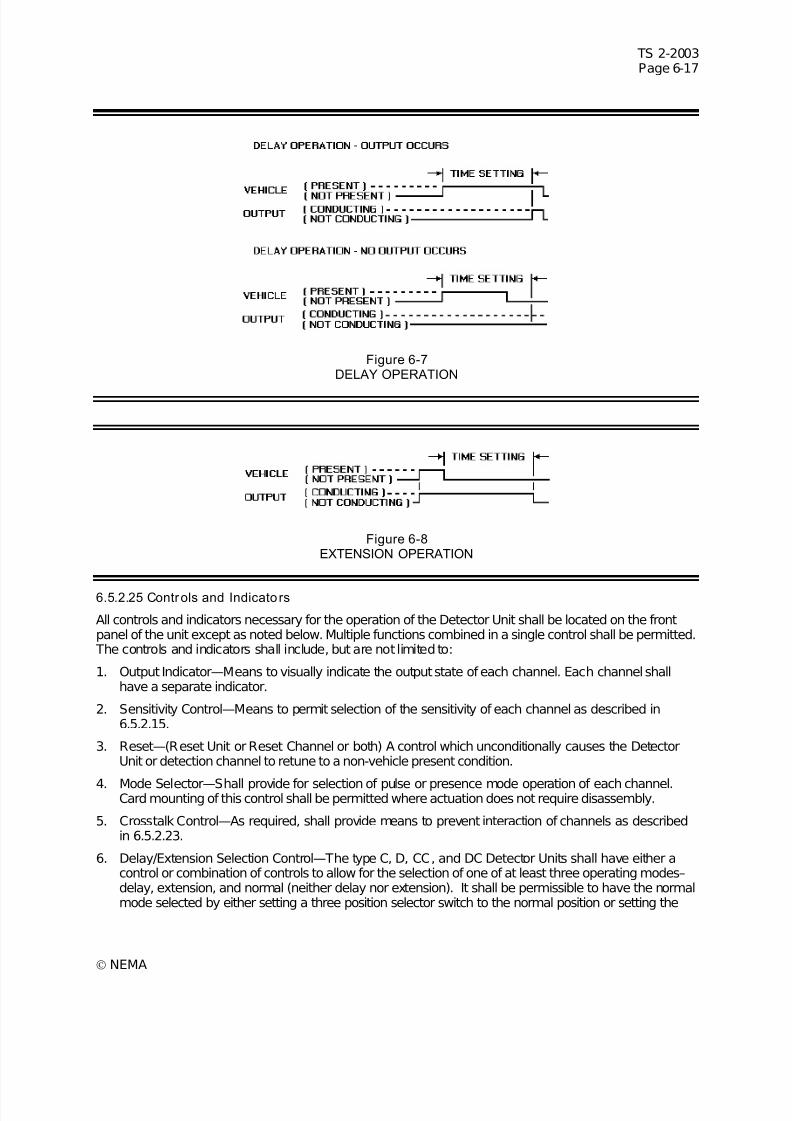
7/30/2019 NEMA TS2-2003- Traffic Controller Assemb
http://slidepdf.com/reader/full/nema-ts2-2003-traffic-controller-assemb 227/246
TS 2-2003Page 6-17
© NEMA
Figure 6-7DELAY OPERATION
Figure 6-8EXTENSION OPERATION
6.5.2.25 Controls and Indicators
All controls and indicators necessary for the operation of the Detector Unit shall be located on the frontpanel of the unit except as noted below. Multiple functions combined in a single control shall be permitted. The controls and indicators shall include, but are not limited to:
1. Output Indicator—Means to visually indicate the output state of each channel. Each channel shallhave a separate indicator.
2. Sensitivity Control—Means to permit selection of the sensitivity of each channel as described in6.5.2.15.
3. Reset—(Reset Unit or Reset Channel or both) A control which unconditionally causes the DetectorUnit or detection channel to retune to a non-vehicle present condition.
4. Mode Selector—Shall provide for selection of pulse or presence mode operation of each channel.Card mounting of this control shall be permitted where actuation does not require disassembly.
5. Crosstalk Control—As required, shall provide means to prevent interaction of channels as describedin 6.5.2.23.
6. Delay/Extension Selection Control—The type C, D, CC, and DC Detector Units shall have either acontrol or combination of controls to allow for the selection of one of at least three operating modes–delay, extension, and normal (neither delay nor extension). It shall be permissible to have the normalmode selected by either setting a three position selector switch to the normal position or setting the

7/30/2019 NEMA TS2-2003- Traffic Controller Assemb
http://slidepdf.com/reader/full/nema-ts2-2003-traffic-controller-assemb 228/246
TS 2-2003Page 6-18
© NEMA
delay/extension timing control to zero. Card mounting of the control(s) shall be permitted whereactuation does not require disassembly.
7. Delay/Extension Timing Control—The type C, D, CC, and DC Detector Units shall provide a means topermit setting of the time duration of the delay/extension period for each channel as described in6.5.2.24. Card mounting of this control shall be permitted where actuation does not require
disassembly.
8. Enable/disable—Means to turn ON (enable) or OFF (disable) a channel or number of channels on aDetector Unit.
6.5.2.26 Outputs
6.5.2.26.1 Solid State Channel Detection Outputs
The output interface of each channel shall be an independent, isolated, solid-state output. Each outputdevice shall have the following characteristics:
1. Output Solid-State Device—The output shall be conducting when a vehicle is detected or when theloop circuit is in a failed state (i.e. open loop or shorted loop). The channel Disabled (OFF) conditionshall have the output in the non-conducting state. During a Reset (Reset Unit or Reset Channel)
condition the output shall be in the conducting state.2. DC Supply Voltage Failure Condition—The output shall be conducting when it is terminated to a
NEMA defined input, indicating a detection output condition.
3. Output Circuit Isolation—The isolation between each output device terminal pair and all otherterminals shall exceed:
a. Resistance >106
ohms
b. Breakdown >1000 V rms
4. Output Rating—The output shall conduct a minimum of 20 milliamperes with a maximum 3.5 volt dropacross the output terminals in the conducting state. The output shall conduct a maximum of 500microamperes with any voltage between 0 and 26 VDC applied across the output terminals in thenon-conductive state.
5. Transition Time—When switching to or from a steady state current in the range of 2.4 to 20milliamperes, the transition time from 8 to 16 volts and vice versa shall be 0.1 milliseconds or less. The circuit(s) to which the output is connected is defined in3.3.5.1.3.
6. Maximum Voltage—When in the non-conducting state, the output shall tolerate a voltage as high as30 VDC without damage.
6.5.2.26.2 Channel Status outputs
Each Detector Unit channel shall provide a channel status output. The channel status output shall be asolid state device with the following characteristics:
1. Output Solid State Device—The output shall be conducting when the channel is operating properly. The channel Disabled (OFF) condition shall have the output in the non-conductive state. During aReset (Reset Unit or Reset Channel) condition the output shall be in the non-conducting state.
2. DC Supply Voltage Failure Condition—Output device is nonconductive, indicating a fault condition.
3. Status Outputs shall be referenced to logic ground.
4. Output Rating—The output shall conduct a minimum of 20 milliamperes with a maximum 3.5 volt dropacross the output terminals in the conducting state. The output shall conduct a maximum of 100microamperes with any voltage between 0 and 26 VDC applied across the output terminals in thenon-conductive state.
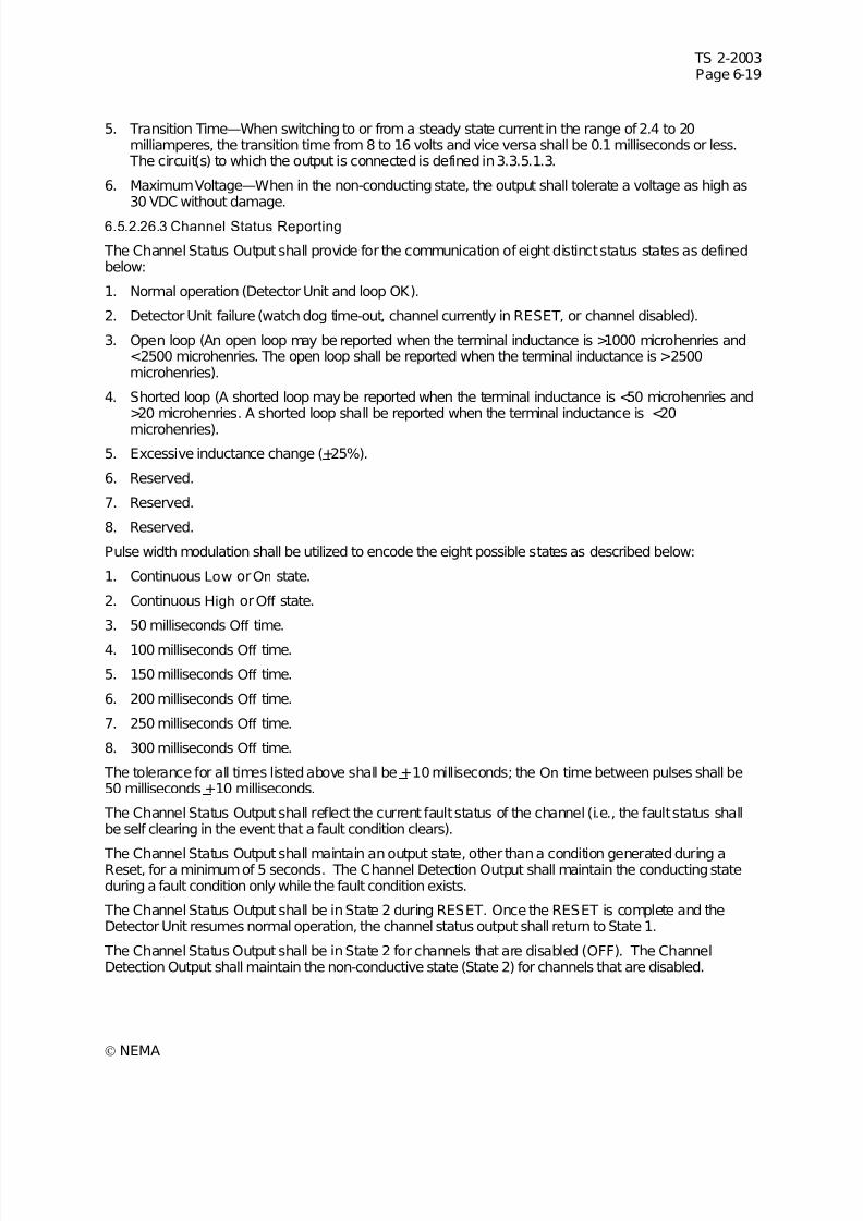
7/30/2019 NEMA TS2-2003- Traffic Controller Assemb
http://slidepdf.com/reader/full/nema-ts2-2003-traffic-controller-assemb 229/246
7/30/2019 NEMA TS2-2003- Traffic Controller Assemb
http://slidepdf.com/reader/full/nema-ts2-2003-traffic-controller-assemb 230/246
TS 2-2003Page 6-20
© NEMA
The last channel failure status shall be stored in memory for future reference. Enunciation of the lastfailure status shall be accomplished through the use of the front panel indicators. If power is removed orthe Reset is activated, the last channel status information shall be cleared.
The particular method employed to enunciate past failure status is not specified and will be manufacturerspecific. (Authorized Engineering Information.)
6.5.2.26.4 Data Transmit Output (TX)
This output shall have 3 states: Mark, Space, and High Impedance. The output shall be in the HighImpedance state except when transmitting to the BIU. The transmitter output shall go from the HighImpedance state to the Mark state until the first Start Bit is sent. The Transition Region shall be definedas any voltage between a Mark and a Space.
6.5.2.26.4.1 Mark State (Binary 1)
During Mark, the TX output shall be less than 0.5 VDC when sinking 4 milliamps current.
6.5.2.26.4.2 Space State (Binary 0)
During Space, the TX output shall be greater than 3.5 VDC when sourcing 4 milliamps current.
6.5.2.26.4.3 High Impedance State The TX output shall have an impedance greater that 1 Megohm in the High Impedance state. Whenconnected to the following loads, the TX output in the High Impedance state:
1. Shall be >8.5 VDC when connected to +12 VDC through 30 Kohm.
2. Shall be >16 VDC when connected to +22 VDC through 11 Kohm.
6.5.2.26.4.4 Output Impedance During Power Off
When power is OFF, the output impedance shall be greater that 300 ohms when measured with anapplied voltage not greater than 2 volts in magnitude to circuit common.
6.5.2.26.4.5 TX Output Shorts
The TX output shall not be damaged under these situations:
1. The TX output shall be capable of withstanding a continuous short to DC common.
2. The TX output shall be capable of withstanding a continuous short to +26 VDC through 600 ohms.
6.5.2.26.4.6 Rise/Fall Time
The transition time from the Space to the Mark voltage or from the Mark to the Space voltage shall be lessthan 2.5 microseconds or 4% of a bit time, whichever is less. This shall apply with 3750 picofarads attachedto the TX output. There shall be no reversal of the direction of voltage change while the signal is in the Transition Region. The Transition Region shall not be reentered until the next change of signal condition.
6.5.2.26.4.7 Transient Withstand
The TX output shall not be damaged by application of the transients described in2.1.7.1 through 2.1.7.5.
6.5.2.27 Communication Port Funct ional Requirements
The protocol for this port is under definition.
Inductive Loop Detector Unit types AC, BC, CC, and DC have this communication port.
6.5.2.27.1 Communication Port Electrical Requi rements
This port, RX and TX and DC Common, is an unbalanced, +5 volt nominal, standard NRZ (Mark/Space)format, asynchronous serial communication port. For compatibility with systems currently in use, when TXis shorted to the Ch 2(+) Output and when RX is shorted to the Ch 4(+) Output, TX and RX must not
7/30/2019 NEMA TS2-2003- Traffic Controller Assemb
http://slidepdf.com/reader/full/nema-ts2-2003-traffic-controller-assemb 231/246
TS 2-2003Page 6-21
© NEMA
interfere with Ch 2(+) or Ch 4(+) operation See 6.5.2.9 for RX specification details and 6.5.2.26.4 for TXspecification details.
6.5.2.27.2 Baud Rate
The port shall be capable of operation at a baud rate of 9600 bps ±1%. The width of 1 bit shall be the
reciprocal of the baud rate.6.5.2.27.3 Communication Parameters
The standard NRZ (Mark/Space) format shall be used. Further specifications are under definition.
6.5.2.27.4 Slot Addresses
The address of a Detector Unit slot is "hard-wired" at each Detector Rack connector. A logic 1 shall becreated by wiring an address pin to DC Common. Open or +24VDC shall be a logic 0. Slot 1 shall beAddress 0 and Slot 15 shall be Address 14.
6.5.2.28 Electri cal Connections
6.5.2.28.1 Connector Description
Two and four channel card rack units shall mate with a 44 terminal, double row, 3.2 mm (0.156 in.)
contact spacing, Cinch J ones card edge connection 50-44A-30M, or equivalent.
6.5.2.28.2 Connector Terminations
Input / Output connector pin terminations shall be as shown in Table 6-2.
6.5.2.28.3 Type A Two Channel Without Delay / Extension Timing
The following pins shall be inactive: P, R, S, T, U, V, Y, Z, 1, 2, 13, 14, 16, 17, 18, and 22.
6.5.2.28.4 Type B Four Channel Without Delay / Extension Timing
The following pins shall be inactive: 1 and 2.
6.5.2.28.5 Type C Two Channel With Delay / Extension Timing
The following pins shall be inactive: P, R, S, T, U, V, Y, Z, 13, 14, 16, 17, 18, and 22.
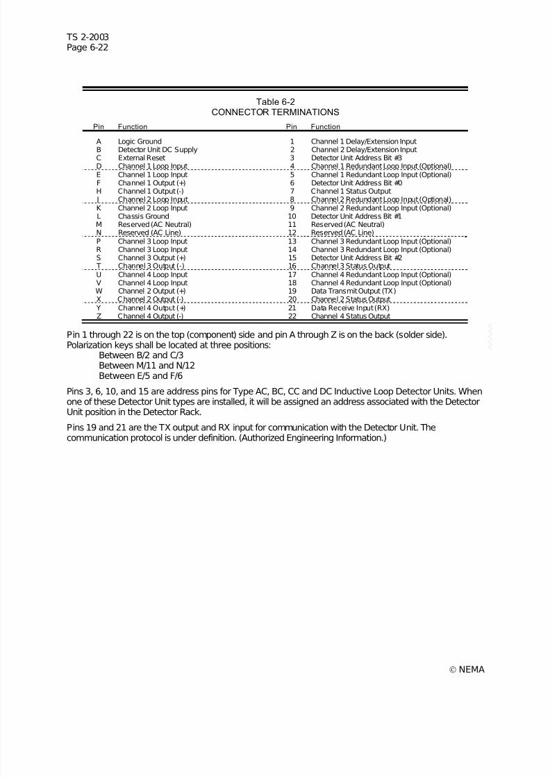
7/30/2019 NEMA TS2-2003- Traffic Controller Assemb
http://slidepdf.com/reader/full/nema-ts2-2003-traffic-controller-assemb 232/246
TS 2-2003Page 6-22
© NEMA
Table 6-2CONNECTOR TERMINATIONS
Pin Function Pin Function
A Logic Ground 1 Channel 1 Delay/Extension InputB Detector Unit DC Supply 2 Channel 2 Delay/Extension InputC External Reset 3 Detector Unit Address Bit #3D Channel 1 Loop Input 4 Channel 1 Redundant Loop Input (Optional)E Channel 1 Loop Input 5 Channel 1 Redundant Loop Input (Optional)F Channel 1 Output (+) 6 Detector Unit Address Bit #0H Channel 1 Output (-) 7 Channel 1 Status Output J Channel 2 Loop Input 8 Channel 2 Redundant Loop Input (Optional)K Channel 2 Loop Input 9 Channel 2 Redundant Loop Input (Optional)L Chassis Ground 10 Detector Unit Address Bit #1M Reserved (AC Neutral) 11 Reserved (AC Neutral)N Reserved (AC Line) 12 Reserved (AC Line)P Channel 3 Loop Input 13 Channel 3 Redundant Loop Input (Optional)R Channel 3 Loop Input 14 Channel 3 Redundant Loop Input (Optional)S Channel 3 Output (+) 15 Detector Unit Address Bit #2 T Channel 3 Output (-) 16 Channel 3 Status Output
U Channel 4 Loop Input 17 Channel 4 Redundant Loop Input (Optional)V Channel 4 Loop Input 18 Channel 4 Redundant Loop Input (Optional)W Channel 2 Output (+) 19 Data Transmit Output (TX)X Channel 2 Output (-) 20 Channel 2 Status Output Y Channel 4 Output (+) 21 Data Receive Input (RX)Z Channel 4 Output (-) 22 Channel 4 Status Output
Pin 1 through 22 is on the top (component) side and pin A through Z is on the back (solder side).Polarization keys shall be located at three positions:
Between B/2 and C/3Between M/11 and N/12Between E/5 and F/6
Pins 3, 6, 10, and 15 are address pins for Type AC, BC, CC and DC Inductive Loop Detector Units. Whenone of these Detector Unit types are installed, it will be assigned an address associated with the DetectorUnit position in the Detector Rack.
Pins 19 and 21 are the TX output and RX input for communication with the Detector Unit. Thecommunication protocol is under definition. (Authorized Engineering Information.)
7/30/2019 NEMA TS2-2003- Traffic Controller Assemb
http://slidepdf.com/reader/full/nema-ts2-2003-traffic-controller-assemb 233/246
TS 2-2003Page 7-1
© NEMA
SECTION 7CABINETS
This section defines the physical and functional requirements of cabinets which fully conform to thisstandard publication.
7.1 DEFINITIONS
These definitions define the nomenclature frequently used in this part of the Standard Publication.
The abbreviations used in this section are defined as follows:
ASTM—American Society for Testing and Materials
7.2 MATERIALS
Cabinets shall be of either a ferrous material or of an aluminum alloy.7.2.1 Cabinets of Ferrous Material
Cabinets shall be fabricated of carbon sheet steel having a minimum thickness of 1.85 millimeters (0.073in.), minimum. The material shall meet the requirements in ASTM Specification No. A-245-48T(paragraph4) or have a heat treated zinc coating of 0.015 mm (0.0006 in.) minimum thickness on bothsides. All exterior seams shall meet the requirements for Type 4 enclosures according to NEMAStandards Publication 250-1991.
7.2.2 Cabinets of Aluminum Alloy
Cabinets shall be fabricated of either sheet aluminum or cast aluminum.
7.2.2.1 Sheet Aluminum
Cabinets shall be fabricated from 3.175 mm (0.125 in.) minimum thickness aluminum alloy sheet meetingthe requirements in ASTM Specification No. 5052-H32 or equivalent. All exterior seams shall meet therequirements for Type 4 enclosures according to NEMA Standards Publication 250-1991.
7.2.2.2 Cast Aluminum
Cabinets shall be fabricated from aluminum alloy meeting the requirements in ASTM Specification No.356-75 or equivalent. Flat cast surfaces exceeding 30.48 cm (12 in.) in both directions shall have athickness of 6.35 mm (0.25 in.), minimum. Flat cast surfaces not exceeding 30.48 cm (12 in.) in bothdirections shall have a thickness of 4.75 mm (0.187 in.).
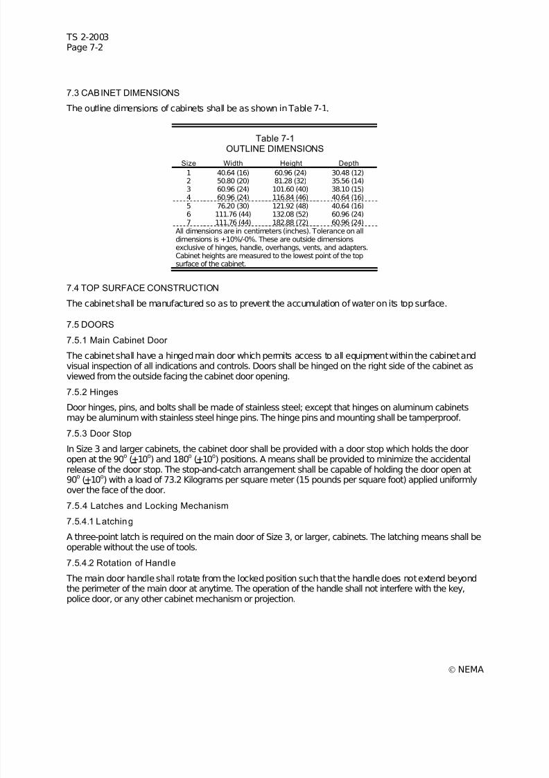
7/30/2019 NEMA TS2-2003- Traffic Controller Assemb
http://slidepdf.com/reader/full/nema-ts2-2003-traffic-controller-assemb 234/246
TS 2-2003Page 7-2
© NEMA
7.3 CABINET DIMENSIONS
The outline dimensions of cabinets shall be as shown in Table 7-1.
Table 7-1OUTLINE DIMENSIONS
Size Width Height Depth
1 40.64 (16) 60.96 (24) 30.48 (12)2 50.80 (20) 81.28 (32) 35.56 (14)3 60.96 (24) 101.60 (40) 38.10 (15)4 60.96 (24) 116.84 (46) 40.64 (16)5 76.20 (30) 121.92 (48) 40.64 (16)6 111.76 (44) 132.08 (52) 60.96 (24)7 111.76 (44) 182.88 (72) 60.96 (24)
All dimensions are in centimeters (inches). Tolerance on alldimensions is +10%/-0%. These are outside dimensionsexclusive of hinges, handle, overhangs, vents, and adapters.Cabinet heights are measured to the lowest point of the topsurface of the cabinet.
7.4 TOP SURFACE CONSTRUCTION
The cabinet shall be manufactured so as to prevent the accumulation of water on its top surface.
7.5 DOORS
7.5.1 Main Cabinet Door
The cabinet shall have a hinged main door which permits access to all equipment within the cabinet andvisual inspection of all indications and controls. Doors shall be hinged on the right side of the cabinet asviewed from the outside facing the cabinet door opening.
7.5.2 Hinges
Door hinges, pins, and bolts shall be made of stainless steel; except that hinges on aluminum cabinetsmay be aluminum with stainless steel hinge pins. The hinge pins and mounting shall be tamperproof.
7.5.3 Door Stop
In Size 3 and larger cabinets, the cabinet door shall be provided with a door stop which holds the dooropen at the 90
o(+10
o) and 180
o(+10
o) positions. A means shall be provided to minimize the accidental
release of the door stop. The stop-and-catch arrangement shall be capable of holding the door open at90o (+10o) with a load of 73.2 Kilograms per square meter (15 pounds per square foot) applied uniformlyover the face of the door.
7.5.4 Latches and Locking Mechanism
7.5.4.1 Latching
A three-point latch is required on the main door of Size 3, or larger, cabinets. The latching means shall be
operable without the use of tools.
7.5.4.2 Rotation of Handle
The main door handle shall rotate from the locked position such that the handle does not extend beyondthe perimeter of the main door at anytime. The operation of the handle shall not interfere with the key,police door, or any other cabinet mechanism or projection.

7/30/2019 NEMA TS2-2003- Traffic Controller Assemb
http://slidepdf.com/reader/full/nema-ts2-2003-traffic-controller-assemb 235/246
TS 2-2003Page 7-3
© NEMA
7.5.4.3 LOCKS
All cabinets shall be provided with a main door lock, Corbin No. 15481RS, or equivalent, constructed of brass or stainless steel which shall operate with a traffic industry conventional No. 2 key, Corbin No.1R6380, or equivalent. Two keys shall be furnished with each cabinet. When in the locked position, thelock shall prevent the movement of latching mechanism.
7.5.4.4 Provisions for Padlock
Cabinets with three-point latches shall be provided with a means of externally padlocking the latchingmechanism. A lock with a 9.525 mm (0.375 in.) diameter shackle shall be accommodated.
7.5.5 Door Opening
The main door opening of all cabinets shall be at least 80 percent of the area of the side which the doorcloses, exclusive of the area for plenums.
7.5.6 Gasketing
Gasketing shall be provided on all door openings and shall be dust-tight. Gaskets shall be attached with apermanent adhesive bond. The mating surface of the gasketing shall be covered with a silicone lubricantto prevent sticking to the mating surface.
7.5.7 Police Compartment
7.5.7.1 Door
A hinged police compartment door shall be provided on the outside face of the main cabinet door. Thedoor shall permit access to a switch panel, but shall not allow access to exposed electrical terminals orother equipment within the cabinet.
7.5.7.2 Locks
The police compartment door shall be provided with a lock which can be operated by a police key, Corbin Type Blank No. 04266 or equivalent. Two keys shall be furnished with each cabinet.
7.5.7.3 Compartment Size
The volume of the police panel compartment with the door closed shall be 1147 cubic centimeters (70cubic inches), minimum. Minimum internal dimensions shall be 12.70 cm (5 in.) high, 25.40 cm (10 in.)wide and 7.62 cm (3 in.) deep.
7.6 SHELVES
The cabinet shall be provided with a sufficient number and sizes of substantial metal shelves or bracketsto support the controller unit and auxiliary equipment. The equipment and shelves shall be arranged sothat it is possible to remove any piece of auxiliary equipment from the cabinet without removing any otherpiece of auxiliary equipment.
7.6.1 Positioning
Size 3, 4, and 5 cabinets shall have provision for positioning shelves to within 30.48 cm (12 in.) of thebottom of the cabinet and to within 20.32 cm (8 in.) of the top of the cabinet in increments of not more
than 5.08 cm (2 in.).Size 6 and 7 cabinets shall have provisions for positioning shelves within 60.96 cm (24 in.) of the bottomof the cabinet and to within 20.32 cm (8 in.) of the top of the cabinet in increments of not more than 5.08cm (2 in.).

7/30/2019 NEMA TS2-2003- Traffic Controller Assemb
http://slidepdf.com/reader/full/nema-ts2-2003-traffic-controller-assemb 236/246
TS 2-2003Page 7-4
© NEMA
7.7 FINISH AND SURFACE PREPARATION
7.7.1 Steel Cabinets
7.7.1.1 Preparation
The surface of the cabinet shall be suitably prepared prior to painting. If the surface is damaged, theaffected area shall be repaired prior to painting.
7.7.1.2 Prime Coat
If a primer coat is used, at least one application of a suitable primer paint shall be applied to the interiorand exterior surfaces of the cabinet. If the primed surface is scratched or damaged, the affected areashall be reprimed prior to the application of the finish coat.
7.7.1.3 Interior Surfaces
At least one application of a suitable exterior grade of paint shall be applied to the interior surfaces of thecabinet.
7.7.1.4 Exterior Surfaces
At least one application of a suitable exterior grade paint shall be applied to the exterior surfaces of the
cabinet.
7.7.2 Aluminum Cabinets
7.7.2.1 Preparation: Painted Cabinets
The surfaces of the cabinet shall be suitably prepared prior to painting. If the surface is damaged, theaffected area shall be repaired prior to painting.
7.7.2.2 Prime Coat
If a primer paint is used, at least one application of a suitable primer paint shall be applied to the surfacesto be painted. If the primed surface is scratched or damaged, the affected area shall be reprimed prior tothe application of the finish coat.
7.7.2.3 Interior Surfaces
If interior surfaces are painted, at least one application of a suitable exterior grade paint shall be appliedto the interior surfaces of the cabinet.
7.7.2.4 Exterior Surfaces
At least one application of a suitable exterior grade paint shall be applied to the exterior surfaces of thecabinet.
7.7.3 Unpainted Aluminum Cabinets
Unpainted aluminum cabinets shall be fabricated from mill finish material and shall be cleaned withappropriate methods that will remove oil film, weld black, mill ink marks and render the surface clean,smooth, and non-sticky to the touch.
7.8 CABINET MOUNTING
7.8.1 Pole-Mounted Cabinets
Cabinets intended for side of pole mounting shall be provided with the hardware necessary to permitmounting to a 30.48 cm (12 in.) outside diameter pole.
7.8.2 Pedestal-Mounted Cabinets
Cabinets intended for pedestal mounting shall be provided with the hardware necessary to permit posttop mounting on a 11.43 cm (4.5 in.) outside diameter pedestal pole.
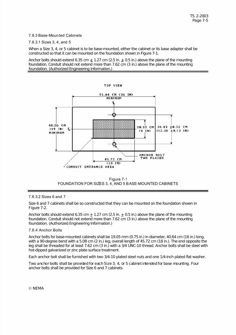
7/30/2019 NEMA TS2-2003- Traffic Controller Assemb
http://slidepdf.com/reader/full/nema-ts2-2003-traffic-controller-assemb 237/246
TS 2-2003Page 7-5
© NEMA
7.8.3 Base-Mounted Cabinets
7.8.3.1 Sizes 3, 4, and 5
When a Size 3, 4, or 5 cabinet is to be base-mounted, either the cabinet or its base adapter shall beconstructed so that it can be mounted on the foundation shown in Figure 7-1.
Anchor bolts should extend 6.35 cm + 1.27 cm (2.5 in. + 0.5 in.) above the plane of the mountingfoundation. Conduit should not extend more than 7.62 cm (3 in.) above the plane of the mountingfoundation. (Authorized Engineering Information.)
Figure 7-1FOUNDATION FOR SIZES 3, 4, AND 5 BASE-MOUNTED CABINETS
7.8.3.2 Sizes 6 and 7
Size 6 and 7 cabinets shall be so constructed that they can be mounted on the foundation shown inFigure 7-2.
Anchor bolts should extend 6.35 cm + 1.27 cm (2.5 in. + 0.5 in.) above the plane of the mountingfoundation. Conduit should not extend more than 7.62 cm (3 in.) above the plane of the mountingfoundation. (Authorized Engineering Information.)
7.8.4 Anchor Bolts
Anchor bolts for base-mounted cabinets shall be 19.05 mm (0.75 in.) in diameter, 40.64 cm (16 in.) long,with a 90-degree bend with a 5.08 cm (2 in.) leg; overall length of 45.72 cm (18 in.). The end opposite theleg shall be threaded for at least 7.62 cm (3 in.) with a 3/4 UNC-10 thread. Anchor bolts shall be steel withhot-dipped galvanized or zinc plate surface treatment.
Each anchor bolt shall be furnished with two 3/4-10 plated steel nuts and one 1/4-inch plated flat washer.
Two anchor bolts shall be provided for each Size 3, 4, or 5 cabinet intended for base mounting. Fouranchor bolts shall be provided for Size 6 and 7 cabinets.
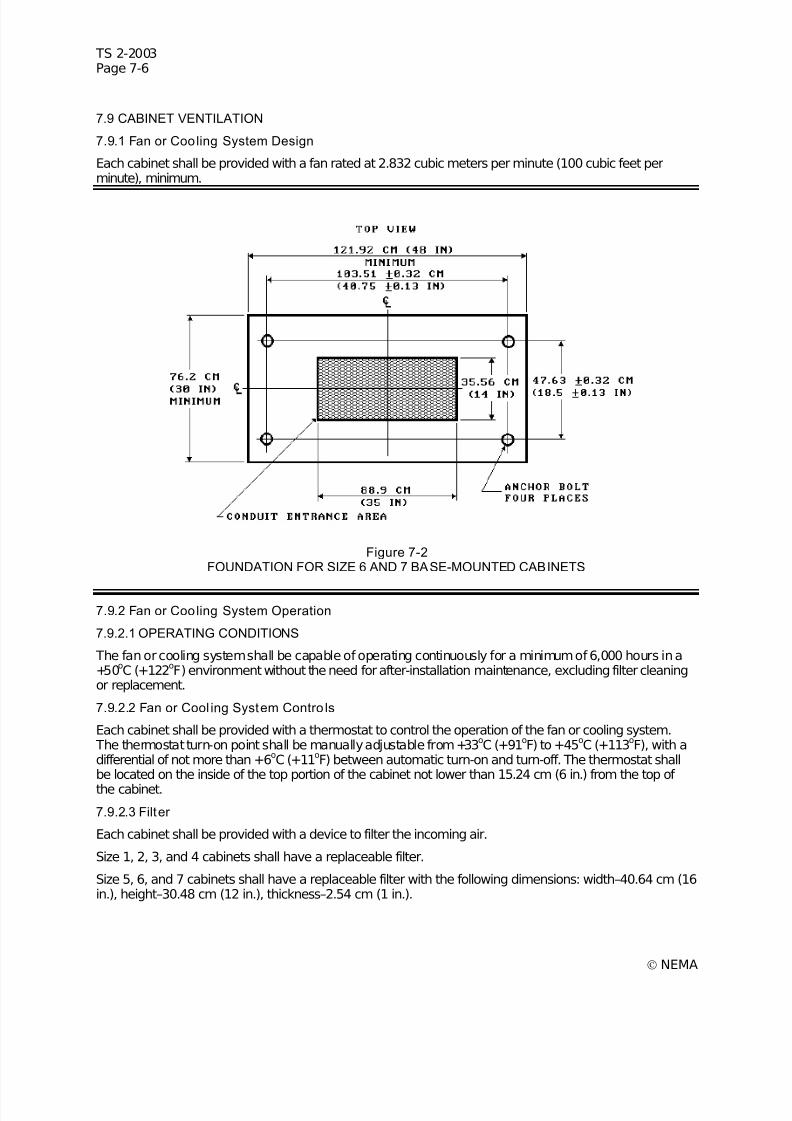
7/30/2019 NEMA TS2-2003- Traffic Controller Assemb
http://slidepdf.com/reader/full/nema-ts2-2003-traffic-controller-assemb 238/246
TS 2-2003Page 7-6
© NEMA
7.9 CABINET VENTILATION
7.9.1 Fan or Cooling System Design
Each cabinet shall be provided with a fan rated at 2.832 cubic meters per minute (100 cubic feet perminute), minimum.
Figure 7-2FOUNDATION FOR SIZE 6 AND 7 BASE-MOUNTED CABINETS
7.9.2 Fan or Cooling System Operation
7.9.2.1 OPERATING CONDITIONS
The fan or cooling system shall be capable of operating continuously for a minimum of 6,000 hours in a+50
oC (+122
oF) environment without the need for after-installation maintenance, excluding filter cleaning
or replacement.
7.9.2.2 Fan or Cool ing System Contro ls
Each cabinet shall be provided with a thermostat to control the operation of the fan or cooling system. The thermostat turn-on point shall be manually adjustable from +33
oC (+91
oF) to +45
oC (+113
oF), with a
differential of not more than +6oC (+11
oF) between automatic turn-on and turn-off. The thermostat shall
be located on the inside of the top portion of the cabinet not lower than 15.24 cm (6 in.) from the top of
the cabinet.
7.9.2.3 Filter
Each cabinet shall be provided with a device to filter the incoming air.
Size 1, 2, 3, and 4 cabinets shall have a replaceable filter.
Size 5, 6, and 7 cabinets shall have a replaceable filter with the following dimensions: width–40.64 cm (16in.), height–30.48 cm (12 in.), thickness–2.54 cm (1 in.).
7/30/2019 NEMA TS2-2003- Traffic Controller Assemb
http://slidepdf.com/reader/full/nema-ts2-2003-traffic-controller-assemb 239/246
TS 2-2003Page 8-1
© NEMA
SECTION 8BUS INTERFACE UNIT
8.1 GENERAL
The BIU performs the interface between Port 1 at the CU and the TF, Loop Detector Rack(s), and otherdevices. Its functions include controlling load switch outputs, Detector Resets, communicating withInductive Loop Detectors and other devices (BIU2), and the conditioning and conversion of TF and LoopDetector call inputs for the CU.
8.2 PHYSICAL
8.2.1 Material
All ferrous metal parts shall be protected against corrosion. All materials shall be moisture and fungus
resistant.8.2.2 Printed Circuit s
Printed circuits shall meet the requirements of 3.2.3.
8.2.3 Dimensions
The BIU shall be 59.436 mm (2.34 in.) W x 114.3 mm (4.50 in.) H x 165.1 mm (6.50 in.) D as illustrated inFigure 8-1.
The BIU assembly shall slide freely into two card guides, each having a nominal slot width of 1.905 mm(.075 in.) and a maximum slot depth of 3.175 mm (.125 in.). The edges of the BIU assembly shall be clearof protrusions on both sides for an area of 3.175 mm (.125 in.) in height for the entire length of theassembly. The nominal thickness of the edges of the BIU assembly shall be 1.575 mm (.062 in.) + 0.203mm (.008 in.).
8.3 CONFIGURATIONS
This standard covers Bus Interface Unit configurations as shown in Table 8-1. The BIU type shall beshown on the front panel of the BIU.
Table 8-1BIU TYPES
NEMA BIU Designation Rack Communication Port RX & TX
BIU NoBIU2 Yes
The two BIU types are not keyed differently. It is up to the user to ensure the correct BIU type requiredfor the user’s application is inserted into the rack. (Authorized Engineering Information.)
8.4 ENVIRONMENTAL REQUIREMENTS
The BIU shall perform its specified functions under the conditions set forth in Section 2, EnvironmentalRequirements.
7/30/2019 NEMA TS2-2003- Traffic Controller Assemb
http://slidepdf.com/reader/full/nema-ts2-2003-traffic-controller-assemb 240/246
TS 2-2003Page 8-2
© NEMA
8.5 POWER REQUIREMENTS
The BIU shall require a nominal supply voltage of 24 VDC +2 VDC. A voltage of 16 VDC or less shall beconsidered loss of power and a voltage of 18 VDC or more shall be considered adequate for operation.On initial application of power, current draw shall be limited to a maximum of 1.25 amperes peak. Uponreaching steady state, the BIU shall require no more than 200 mA throughout the voltage range of 16 to
30 VDC.
For testing, a short of +24VDC IN to LOGIC GROUND is considered one form of a loss of power.
The BIU shall not be damaged by insertion to or removal from a powered BIU Rack or Detector Rack.
8.5.1 Initialization
1. Upon application of DC power, the BIU shall be fully functional within 1000 milliseconds. Theinitialized state of the BIU shall set all outputs to the 24 volt level.
2. During the loss of DC power to the BIU for 700 milliseconds or less, the BIU shall maintain the controlstate of its outputs. If DC power is restored to the BIU within 700 milliseconds following the loss of DCpower, the BIU shall maintain the state of its outputs until they are updated by valid Port 1 activity.
Figure 8-1BUS INTERFACE UNIT
3. Following the loss of DC power to the BIU for more than 700 milliseconds and less than 1.5 seconds,the BIU shall operate in accordance with 8.5.1.2 or 8.5.1.4.
4. Following the loss of DC power to the BIU for 1.5 seconds or greater, the BIU shall turn off all of itsoutputs and reinitialize all internal operations upon restoration of DC power.
5. Within 8 milliseconds of loss of power, the BIU shall cease Port 1 Communications. If DC power isrestored to the BIU within 700 milliseconds following the loss of DC power, the BIU shall resume Port1 Communications within 200 milliseconds of restoration of power.

7/30/2019 NEMA TS2-2003- Traffic Controller Assemb
http://slidepdf.com/reader/full/nema-ts2-2003-traffic-controller-assemb 241/246
TS 2-2003Page 8-3
© NEMA
8.6 INDICATORS
The BIU shall have two status indicators to represent adequate supply voltage, internal operations, andvalid communications.
8.6.1 Power On Ind icator
This indicator shall illuminate when the applied DC voltage is considered adequate as described in 8.5and the BIU internal logic is operating properly. This indicator shall be OFF if either of these conditionsare false.
8.6.2 Port 1 Indicator
This indicator shall illuminate for a duration not less than 20 milliseconds and not more than 50milliseconds each time the BIU transmits on its Port 1 output.
8.6.3 Rack TX Indicator (BIU2 Only)
This indicator shall illuminate for a duration not less than 20 milliseconds and not more than 50milliseconds each time the BIU transmits on its rack TX output.
8.7 BIU-TO-RACK COMMUNICATION PORT FUNCTIONAL REQUIREMENTS (BIU2 ONLY)
The protocol for this communication port is under definition.
8.7.1 Communication Port Electrical Requirements
This port (RX and TX and Logic Ground) is an unbalanced, +5 volt nominal, NRZ (Non-Return To Zero)format, asynchronous serial communication port. See BIU Data Receive Input (RX) 8.8.5.5 for RXspecification details and Data Transmit Output (TX) in 8.8.4.1 for TX specification details.
8.7.2 Baud Rate
The port shall be capable of operation at a baud rate of 9600 bps ±1%. The width of 1 bit shall be thereciprocal of the baud rate.
8.8 INTERFACE REQUIREMENTS
8.8.1 Port 1 Communications
Defined in 3.3.1.
8.8.2 Port 1 Connector
The Port 1 connector shall be a 15 pin metal shell “D” sub miniature type. The connector shall utilizefemale contacts with 15 millionths of an inch minimum gold plating in the mating area. The connectorshall be equipped with latching blocks. The connector shall intermate with a 15 pin D type connector,Amp Incorporated part number 205206-1, or equivalent, which is equipped with spring latches, AmpIncorporated part number 745012-1, or equivalent.
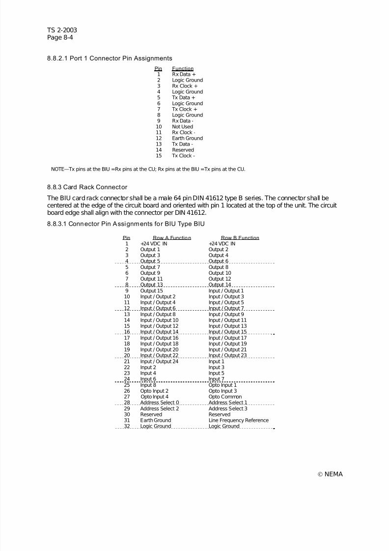
7/30/2019 NEMA TS2-2003- Traffic Controller Assemb
http://slidepdf.com/reader/full/nema-ts2-2003-traffic-controller-assemb 242/246
TS 2-2003Page 8-4
© NEMA
8.8.2.1 Port 1 Connector Pin Assignments
Pin Function 1 Rx Data +2 Logic Ground3 Rx Clock +4 Logic Ground
5 Tx Data +6 Logic Ground7 Tx Clock +8 Logic Ground9 Rx Data -10 Not Used11 Rx Clock -12 Earth Ground13 Tx Data -14 Reserved15 Tx Clock -
NOTE—Tx pins at the BIU =Rx pins at the CU; Rx pins at the BIU =Tx pins at the CU.
8.8.3 Card Rack Connector
The BIU card rack connector shall be a male 64 pin DIN 41612 type B series. The connector shall becentered at the edge of the circuit board and oriented with pin 1 located at the top of the unit. The circuitboard edge shall align with the connector per DIN 41612.
8.8.3.1 Connector Pin Assignments for BIU Type BIU
Pin Row A Function Row B Function 1 +24 VDC IN +24 VDC IN2 Output 1 Output 23 Output 3 Output 44 Output 5 Output 65 Output 7 Output 86 Output 9 Output 107 Output 11 Output 128 Output 13 Output 14
9 Output 15 Input / Output 110 Input / Output 2 Input / Output 311 Input / Output 4 Input / Output 512 Input / Output 6 Input / Output 713 Input / Output 8 Input / Output 914 Input / Output 10 Input / Output 1115 Input / Output 12 Input / Output 1316 Input / Output 14 Input / Output 1517 Input / Output 16 Input / Output 1718 Input / Output 18 Input / Output 1919 Input / Output 20 Input / Output 2120 Input / Output 22 Input / Output 2321 Input / Output 24 Input 122 Input 2 Input 323 Input 4 Input 524 Input 6 Input 7
25 Input 8 Opto Input 126 Opto Input 2 Opto Input 327 Opto Input 4 Opto Common28 Address Select 0 Address Select 129 Address Select 2 Address Select 330 Reserved Reserved31 Earth Ground Line Frequency Reference32 Logic Ground Logic Ground
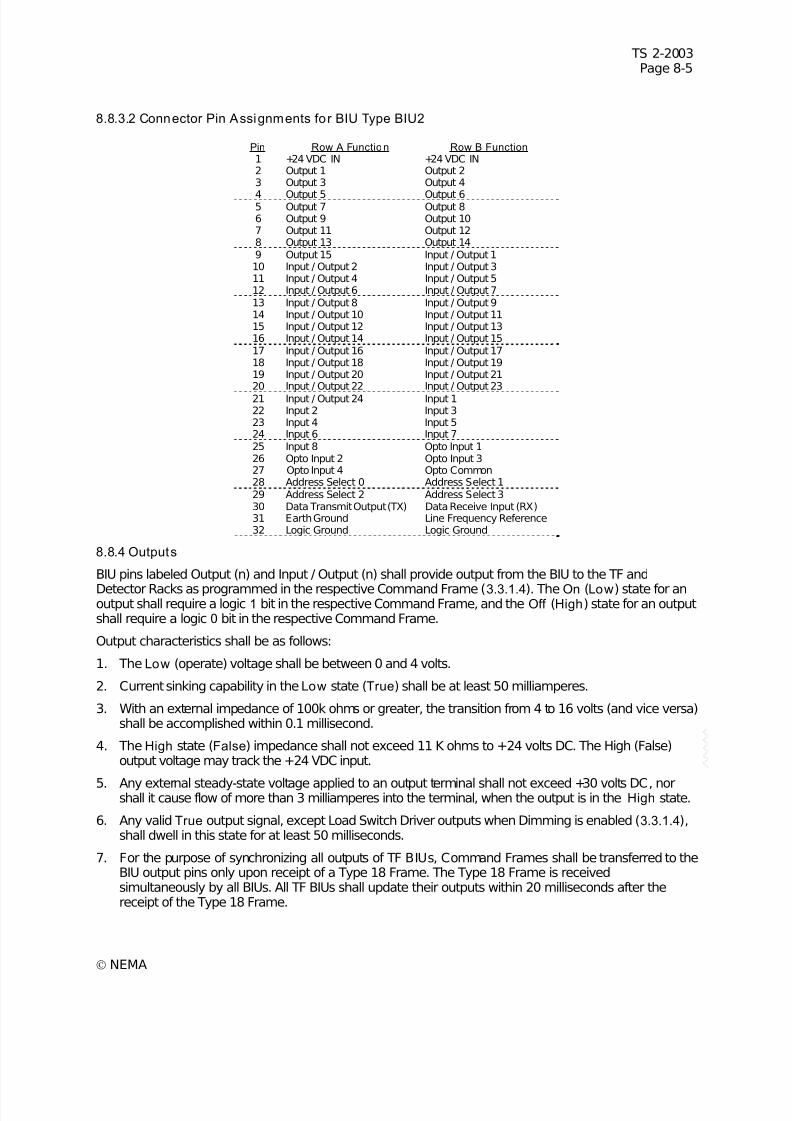
7/30/2019 NEMA TS2-2003- Traffic Controller Assemb
http://slidepdf.com/reader/full/nema-ts2-2003-traffic-controller-assemb 243/246
TS 2-2003Page 8-5
© NEMA
8.8.3.2 Connector Pin Assignments for BIU Type BIU2
Pin Row A Function Row B Function 1 +24 VDC IN +24 VDC IN2 Output 1 Output 23 Output 3 Output 4
4 Output 5 Output 65 Output 7 Output 86 Output 9 Output 107 Output 11 Output 128 Output 13 Output 149 Output 15 Input / Output 110 Input / Output 2 Input / Output 311 Input / Output 4 Input / Output 512 Input / Output 6 Input / Output 713 Input / Output 8 Input / Output 914 Input / Output 10 Input / Output 1115 Input / Output 12 Input / Output 1316 Input / Output 14 Input / Output 1517 Input / Output 16 Input / Output 1718 Input / Output 18 Input / Output 1919 Input / Output 20 Input / Output 2120 Input / Output 22 Input / Output 2321 Input / Output 24 Input 122 Input 2 Input 323 Input 4 Input 524 Input 6 Input 725 Input 8 Opto Input 126 Opto Input 2 Opto Input 327 Opto Input 4 Opto Common28 Address Select 0 Address Select 129 Address Select 2 Address Select 330 Data Transmit Output (TX) Data Receive Input (RX)31 Earth Ground Line Frequency Reference32 Logic Ground Logic Ground
8.8.4 Outputs
BIU pins labeled Output (n) and Input / Output (n) shall provide output from the BIU to the TF and
Detector Racks as programmed in the respective Command Frame (3.3.1.4). The On (Low) state for anoutput shall require a logic 1 bit in the respective Command Frame, and the Off (High) state for an outputshall require a logic 0 bit in the respective Command Frame.
Output characteristics shall be as follows:
1. The Low (operate) voltage shall be between 0 and 4 volts.
2. Current sinking capability in the Low state (True) shall be at least 50 milliamperes.
3. With an external impedance of 100k ohms or greater, the transition from 4 to 16 volts (and vice versa)shall be accomplished within 0.1 millisecond.
4. The High state (False) impedance shall not exceed 11 K ohms to +24 volts DC. The High (False)output voltage may track the +24 VDC input.
5. Any external steady-state voltage applied to an output terminal shall not exceed +30 volts DC, norshall it cause flow of more than 3 milliamperes into the terminal, when the output is in the High state.
6. Any valid True output signal, except Load Switch Driver outputs when Dimming is enabled (3.3.1.4),shall dwell in this state for at least 50 milliseconds.
7. For the purpose of synchronizing all outputs of TF BIUs, Command Frames shall be transferred to theBIU output pins only upon receipt of a Type 18 Frame. The Type 18 Frame is receivedsimultaneously by all BIUs. All TF BIUs shall update their outputs within 20 milliseconds after thereceipt of the Type 18 Frame.
7/30/2019 NEMA TS2-2003- Traffic Controller Assemb
http://slidepdf.com/reader/full/nema-ts2-2003-traffic-controller-assemb 244/246
TS 2-2003Page 8-6
© NEMA
8.8.4.1 Data Transmit Output (TX) for BIU Type BIU2
This output shall have 2 states: Mark and Space. The state shall be a Mark when no data transmissionsare taking place. The Transition Region shall be defined as any voltage between a Mark and a Space.
8.8.4.1.1 Mark State (Binary 1)
During Mark, the TX output shall be less than 0.5 VDC when sinking 4 milliamps DC current.
8.8.4.1.2 Space State (Binary 0)
During Space, the TX output shall be greater than 3.5 VDC when sourcing 4 milliamps DC current.
8.8.4.1.3 Output Impedance During Power Off
When power is OFF, the output impedance shall be greater than 300 ohms when measured with anapplied voltage not greater than 2 volts in magnitude to circuit common.
8.8.4.1.4 TX Output Shorts
The TX output shall not be damaged when shorted to Logic Ground or +5 VDC:
1. The TX output shall be capable of withstanding a continuous short to Logic Ground.
2. The TX output shall be capable of withstanding a continuous short to +5 VDC.
8.8.4.1.5 Rise/Fall Time
The transition time from the Space to the Mark voltage or from the Mark to the Space voltage shall be lessthan 2.5 microseconds or 4% of the bit time, whichever is less. This shall apply with 3750 picofaradsattached to the TX output. There shall be no reversal of the direction of voltage change while the signal is inthe Transition Region. The Transition Region shall not be reentered until the next change of signalcondition.
8.8.4.1.6 Transient Withstand
The TX output shall not be damaged by application of the transients described in 2.1.7.1 through 2.1.7.5.
8.8.5 Inputs
Type 138–141 Frames from a BIU shall report logic 0 bits for False (24V) inputs, and shall report logic 1 bits for True (ground) inputs. Opto Inputs 1 through 4 shall report logic 0 bits when inactive, and shallreport logic 1 bits when active.
BIU Response Frame frequency is discussed in 3.3.1.5. The states of the inputs reported by the BIU shallbe the states of those inputs at the time the Positive Acknowledge Frame is prepared for sending.
Input signal recognition times allow more than 1 valid BIU input state between BIU input ResponseFrame. (Authorized Engineering Information.)
8.8.5.1 Opto Common
The Opto Common input is the common reference pin for four Optically Isolated Inputs.
8.8.5.2 Opto Inputs
The Opto inputs are intended to provide optical isolation for Pedestrian Detector and RemoteInterconnect Inputs. The Opto inputs are intended to connect through external 27 K ohm, 1 Watt resistorsfor 120 VAC operation, and are intended for direct connection to 12 VAC from the cabinet power supplyfor Pedestrian Detector applications. These inputs may alternatively be used for low-true DC applicationswhen the Opto Common pin is connected to the 24 volt supply. (Authorized Engineering Information.)
1. The Opto inputs shall provide electrical isolation of 10 megohms minimum resistance and 1000 VACRMS minimum breakdown to all connector pins except the Opto Common pin.
2. These inputs shall exhibit a nominal impedance to the Opto Common pin of 5000 ohms + 10% to theopto common input.
7/30/2019 NEMA TS2-2003- Traffic Controller Assemb
http://slidepdf.com/reader/full/nema-ts2-2003-traffic-controller-assemb 245/246
TS 2-2003Page 8-7
© NEMA
3. The Opto inputs shall not recognize 3 volts RMS (AC sinusoid or DC) or less relative to the commoninput.
4. The Opto inputs shall recognize 8 volts RMS (AC sinusoid or DC) or more relative to the commoninput.
5. Any steady state voltage applied between an Opto input and the Opto Common shall not exceed 35VAC RMS.
6. Opto inputs shall not be acknowledged when active for 25 milliseconds or less, and shall beacknowledged when active for 50 milliseconds or more.
7. The Opto inputs to the BIU shall conform to 3.3.5.1.2 for voltage transient immunity.
8.8.5.3 Line Frequency Reference
The Line Frequency Reference input pin receives a square wave signal from the cabinet power supplyfor the purpose of synchronizing BIU outputs with the AC line.
Electrical characteristics for this input shall be as follows:
1. A voltage between 0 and 8 volts shall be considered the Low state, and shall occur when the AC line
is in the positive half cycle.2. A voltage between 16 and 26 volts shall be considered the High state, and shall occur when the AC
line is in the negative half cycle.
3. The Line Frequency Reference input shall exhibit a nominal impedance of 10 K ohms + 10% to the+24 VDC input, and shall not have more than 1000 picofarads of load capacitance.
4. The rise and fall time of the signal connected to this input shall not exceed 50 microseconds.
T&F BIUs shall exclude dimming operation when no transition occurs in the Line Frequency Reference input between Frame 18 transfers.
8.8.5.4 24 Volt Signal Inputs
The 24 Volt Signal Inputs to the BIU shall conform to 3.3.5.1.2 and 3.3.5.1.3 except as noted herein.
8.8.5.4.1 Address Select Inputs
The Address Select input bits define the logical position of each BIU. The pins are left open or floatingfor a logical False, and are connected to Logic Ground for a logical True. There shall be 16 uniqueaddress positions selected with a binary code, using bit 0 as least significant and bit 3 as most significant.Address bit connections are illustrated in Section 5, TF.
8.8.5.4.2 Function Inputs
When the Address Select 3 input to the BIU is inactive, the BIU pins labeled Input (n) and Input/Output(n) shall provide input to the BIU from the TF as required in 5.3.1.2.
When the Address Select 3 input to the BIU is active (activating Detector Mode), the Function Inputtiming shall accommodate Loop Detector Calls and channel status as follows:
1. A Detector Call signal dwelling in a defined logic state for less than 0.25 milliseconds shall not berecognized.
2. A Detector Call signal dwelling in a defined logic state for 2 millisecond or more shall be recognized.
3. Each Call input shall activate a time stamp feature within the BIU to enable accurate pulse widthmeasurement. Details on this time stamp may be found in 3.3.1.4.2.6.
4. Detector Channel Status shall be derived from pulse width modulation encoding. These shall conformto the eight status states as outlined in 6.5.2.26.3.
7/30/2019 NEMA TS2-2003- Traffic Controller Assemb
http://slidepdf.com/reader/full/nema-ts2-2003-traffic-controller-assemb 246/246
TS 2-2003Page 8-8
5. The BIU shall have sufficient buffering to accumulate multiple states of Detector Channel Statusbetween the once-per-second polls. Channel Status pulse width sequences already in process at thetime of Type 152–155 Frames shall not be missed or truncated due to asynchronous polling, but shallbe sent in the next poll.
8.8.5.5 Data Receive Input (RX) for BIU Type BIU2
The data receive input, RX, shall have an input impedance 3 Kohm to 7 Kohm and an input capacitanceless than 250 picofarads. This input impedance shall terminate to Logic Ground. The input’s open circuitvoltage shall be less than 09 VDC This inputshall be functional when voltages over therange of±25 VDC