specification for traffic signal cabinet assemblies : nema ts2
TRANSCRIPT
REVISED 12/4/2019
Specification for Traffic Signal Cabinet Assemblies: NEMA TS2 City of Mesa Transportation Department Traffic Engineering ITS Group Cabinets shall include the components listed below to form a completely functional 8-phase traffic signal control cabinet (see specifications for individual component requirements):
QTY-1 Type 16 Malfunction Management Unit (MMU) with Integral Ethernet Port QTY-1 Power Supply QTY-2 Type A detectors (2-channel) QTY-3 Bus Interface Units (BIUs) QTY-8 Load Switches QTY-4 Flash Transfer Relays QTY-1 Solid State Flasher QTY-4 3/4” x 11” galvanized anchor bolts with 5” L bend, each anchor bolt shall include 8 nuts and 4 flat washers
REVISED 12/4/2019
Revisions (are bold in the document): 6/8/11:
1. Added 4 anchor bolts to be provided 2. Added removable cabinet lifting ears. 3. Reduced number of 2 channel detectors to be supplied from 4 to 2 4. GTT Opticom 757 green sense harnesses replaced with GTT 768 interface panel. 5. Replaced references to GTT Opticom 752 with 762 & 764. 6. Revised ADOT TS Standards to 2010 Edition
6/14/11:
1. Added NEMA TS2 Type 2 “A” power cable to allow use of Nema TS2 type 2 Controllers 7/3/12:
1. Reduced the number of load switches to be provided from 12 to 8. 2. Cabinet Construction: Added that police panel will be hinged on the right side. (pg. 4) 3. Power Panel Design and Construction: Changed circuit breaker for controller, MMU, signals, cabinet power supply and
auxiliary panels 20A to 15A (pg. 5) 4. Inside Control Panel Switches: Added to the end of the operation description for the AUTO/FLASH switch: modified flash
reporting (pg. 5) 5. Police Panel Switches: Added to the end of the operation description for the POLICE FLASH switch; modified flash
reporting (pg. 6) 6. Cables: Added that cables will be neatly secured (pg. 6) 7. Backboards and Wire Terminations: Added load resistors to the yellow load switch outputs of channels 9,10,11, &12 (pg.
6) 8. Added RESISTOR PANEL for protected/permitted left turns (pg. 7) 9. Revised Polara Push Button Latching Control Unit. (pg. 8)
12/10/12:
1. Deleted the requirement to include the Polara LBPCU with the cabinet. 2. Cabinet Construction. #9, added the requirement to supply wing nuts on the lifting ear bolts. 3. Cabinet Light Assembly. Changed from 24” fluorescent to 18”-24” LED. (pg. 4) 4. Revised Ped Pushbutton latching push button control unit requirements. To be incorporated into the detector rack.
(pg. 7) 1/10/13:
1. Added Hybrid Buss relay in lieu of Mercury Whetted Relay (Power Distribution Panel, pg.5) 5/6/13:
1. Changed MMU model to EDI MMU2-16LEip, pg. 8 (incorporates flashing yellow arrow logic)
10/15/13: 1. Struther’s Dunn 21XBXPL33-120VAC Flash Transfer relay now required. (Flash Transfer Relays, pg. 8)
12/16/14:
1. Changed requirement from supplying two Type A 2-Channel detectors to supplying four Type A 2-Channel detectors. 2. Added LED lighting under the document drawer. (Pull Out Drawer Assembly, pg. 4) 3. Specified the model of the LED Cabinet light. (Cabinet & Drawer Light Assembly, pg. 4) 4. Gooseneck Light to preferably have an LED Flood lamp installed. (Cabinet & Drawer Light Assembly, pg.4)
1/12/15:
1. Shelf mounted Polara equipment is required. (Refer to DETECTION page 8) This was added on 12/16/14 but this change log page was not updated.
3/05/2018: 1. Cabinet and Drawer Light Assembly-removed CERTIFIED LED Model Cert LED T8-1.5-6-CL-3.5k-MBPR-120VAC and
added Lumecon D1114 LED panel or exact approved equal. 12/4/2019:
1. Delete the requirement to include the Polara LBPCU with the cabinet. 2. Delete the requirement to include GTT Opticom 768 with the cabinet.
REVISED 12/4/2019 PAGE 1
Cabinet Assembly Specifications – Table of Contents
SPECIFICATIONS AND STANDARDS INCORPORATED IN THIS DOCUMENT ........................................................................................................ 2
COMPATIBILITY CLAUSE ...................................................................................................................................................................................... 2
DOCUMENTATION ............................................................................................................................................................................................... 2
WARRANTY STATEMENT & ORIGIN OF MANUFACTURE .................................................................................................................................... 3
CABINET OPERATIONAL STANDARDS ................................................................................................................................................................. 4
CABINET CONSTRUCTION........................................................................................................................................................................................... 4 SHELF HEIGHT.............................................................................................................................................................................................................. 4 VENTILATING FAN ASSEMBLY .................................................................................................................................................................................... 4 AIR FILTER ASSEMBLY ................................................................................................................................................................................................. 4 CABINET & DRAWER LIGHT ASSEMBLIES ................................................................................................................................................................... 4 AUXILIARY GOOSENECK LIGHT ASSMEBLY ................................................................................................................................................................ 4 PULL OUT DRAWER ASSEMBLY .................................................................................................................................................................................. 5 POWER DISTRIBUTION PANEL DESIGN AND CONSTRUCTION: ................................................................................................................................ 5 CONVENIENCE OUTLETS ............................................................................................................................................................................................. 5 INSIDE CONTROL PANEL SWITCHES ........................................................................................................................................................................... 6 POLICE PANEL SWITCHES ........................................................................................................................................................................................... 6 CABLES ......................................................................................................................................................................................................................... 6 WIRE TERMINATION ................................................................................................................................................................................................... 6 BACKBOARDS AND WIRE TERMINATIONS ................................................................................................................................................................. 7 INPUT/OUTPUT TERMINALS ...................................................................................................................................................................................... 7 CONTROLLER UNIT POWER UP .................................................................................................................................................................................. 7 FLASHING OPERATION ............................................................................................................................................................................................... 7 DETECTOR RACK .......................................................................................................................................................................................................... 8 PREEMPTION............................................................................................................................................................................................................... 8 FIELD TERMINAL LOCATIONS ..................................................................................................................................................................................... 8 RESISTOR PANEL ......................................................................................................................................................................................................... 8 BUS INTERFACE UNIT .................................................................................................................................................................................................. 8 CABINET POWER SUPPLY ............................................................................................................................................................................................ 8 FLASH TRANSFER RELAYS ........................................................................................................................................................................................... 9 LOAD SWITCHES .......................................................................................................................................................................................................... 9 SOLID STATE FLASHERS ............................................................................................................................................................................................... 9
MALFUNCTION MANAGEMENT UNIT ................................................................................................................................................................. 9
ACCEPTABLE MALFUNCTION MANAGEMENT UNIT (MMU) TYPES ......................................................................................................................... 9
DETECTION ........................................................................................................................................................................................................... 9
LOOP DETECTOR UNIT ................................................................................................................................................................................................ 9
DRAWING/DIAGRAMS ...................................................................................................................................................................................... 10
CABINET LAYOUT DETAILS ............................................................................................................................................................................................... 10
REVISED 12/4/2019 PAGE 2
Specifications and Standards Incorporated in This Document
1. MESA STANDARD DETAILS AND SPECIFICATIONS AMENDMENT TO MAG UNIFORM STANDARD DETAILS AND SPECIFICATIONS FOR PUBLIC WORKS CONSTRUCTION
2. ARIZONA DEPARTMENT OF TRANSPORTATION SIGNALS AND LIGHTING STANDARD DRAWINGS
3. NATIONAL ELECTRICAL MANUFACTURERS ASSOCIATION, TRAFFIC CONTROL SYSTEMS, NEMA STANDARDS PUBLICATION: TS2-2003
4. INTERNATIONAL MUNICIPAL SIGNAL ASSOCIATION, INC., WIRE AND CABLE SPECIFICATIONS
5. MANUAL ON UNIFORM TRAFFIC CONTROL DEVICES FOR STREETS AND HIGHWAYS USDOT/FHWA
6. AMERICAN ASSOCIATION OF STATE AND HIGHWAY TRANSPORTATION OFFICIALS (AASHTO) STANDARD SPECIFICATIONS FOR STRUCTURAL SUPPORTS FOR HIGHWAY SIGNS, LUMINAIRES AND TRAFFIC SIGNALS
Compatibility Clause
This specification covers deviations and extensions above and beyond the standards incorporated. The Terminal Facility, MMU, Cabinet Power Supply, BIU’s and loop detectors must be fully compatible with the specifications as listed above. In the case of incompatibility or inconsistency between this specification and those incorporated, this specification shall be followed.
Documentation
The City reserves the right to reject traffic signal control equipment and auxiliary equipment items in which the manufacturer of such items does not have at least one million dollars of product liability insurance.
All cabinets shall include complete technical information, shop drawings, schematic diagrams, photographs, circuit diagrams, graphs, instruction manuals, and any other necessary documents to fully describe the proposed equipment.
At the time of delivery, the supplier shall furnish two (2) copies of the programming and operation manuals and 2 copies of the repair documentation for the equipment.
At the time of delivery, the supplier shall provide copies of cabinet manufacturer’s testing procedures/results check list (hard copy and electronic).
At the time of delivery, the supplier shall provide copies of MMU manufacturer’s testing procedures/results check list (hard copy and electronic).
A permanent label with unique serial number and date of manufacture shall be attached to each of the following components:
Bus Interface Unit (BIU) Cabinet Power Supply Loop Detector Unit Malfunction Management Unit (MMU) Cabinet Shell (on the inside of cabinet door) A list of serial numbers and manufacturing dates shall be provided with each cabinet.
REVISED 12/4/2019 PAGE 3
Warranty Statement & Origin of Manufacture
WARRANTY COVERAGE The supplier of equipment shall warranty their product to be free from defect in design and operation and that it meets all the requirements of this specification and those incorporated in this document. ORIGIN OF MANUFACTURE: The following cabinet plug-ins: MMU, BIU, Power supply, Load Switches, Flasher, are to be manufactured in the US. LENGTH OF WARRANTY The term of warranty shall be a minimum of one (1) year from date of shipment for all equipment. Vendor shall state length of warranty in writing. PARTS AVAILABILITY The supplier of equipment shall be able to provide replacement parts for a minimum of five (5) years after the warranty expires. REPLACEMENT COVERAGE All units shall be covered as follows: if a malfunction occurs during the warranty period, the supplier shall, within two (2) weeks after notification, furnish a like unit, module, or auxiliary equipment for use while the warranted unit is being repaired. RELIABILITY CLAUSE While under warranty, the isolation and repair of any unit malfunction shall be the responsibility of the supplier. Any unit experiencing a total of three failures that has twice been returned to the supplier for repair shall be replaced with a new unit of the same type at no charge to the City. The replacement unit's warranty shall be that of a new unit. NOTE: Malfunctions do not include damage caused by lightning, power surges, negligence, acts of God, or use of equipment in a manner not originally intended by its manufacturer. SHIPPING & HANDLING During the warranty period shipping shall be handled as follows: The City of Mesa will pay for shipping the defective component to the vendor and the vendor will pay for return shipping the repaired unit to the City.
REVISED 12/4/2019 PAGE 4
Cabinet Operational Standards
CABINET CONSTRUCTION
Eight phase cabinets NEMA Size 7 shall be supplied. Cabinets shall meet the following criteria:
1. Material shall be 5052-H32 0.125-inch thick aluminum. 2. The aluminum shall have a mill finish per NEMA TS-2 7.7.3. 3. Door hinge shall be of the continuous type with a stainless-steel hinge pin. Rivets shall NOT be used to
attach the hinge. 4. All external fasteners shall be stainless steel. 5. The door handle shall be stainless steel or cast aluminum. 6. Seams around fan or fan mounting plate as well as unwelded cabinet seams shall be sealed with clear
RTV silicone, in order to prevent dust intrusion. 7. There shall be no holes in top of cabinet. 8. The doorstop rod shall be steel. The brackets attaching the stop rod to the door and cabinet shall be
aluminum and welded in place. 9. Removable/reversible cabinet lifting “ears” shall be provided. The bolts shall be captured with WING nuts so tools would not be necessary to reverse the lifting ears. 10. The police panel door shall be hinged on the right and open to the right. SHELF HEIGHT
The cabinet shall have 3 shelves installed. A bottom shelf height of 39 inches, middle shelf height of 51 inches and the top shelf shall be mounted at 64 inches from the bottom of the cabinet. The backboard shall be mounted under the bottom shelf, not behind it. All measurements shall be from the bottom of the cabinet. VENTILATING FAN ASSEMBLY
Two ventilating fans, (COMAIR-ROTRON Model MX2B3 or equivalent), shall be provided and controlled by the thermostat. Each fan motor shall be equipped with sealed ball bearings. Fans shall be mounted inside the cabinet on the left and right above the door opening behind the front top edge of the cabinet (SEE CABINET LAYOUT DETAIL). AIR FILTER ASSEMBLY
Air filter shall be one piece and shall be held firmly in place against the cabinet door in order to prevent dust from bypassing the perimeter of the filter. Wing nuts or thumbscrews are preferred. Air filter shall be a 16-inch x 12-inch x 1-inch disposable pleated filter (SEE CABINET LAYOUT DETAIL). CABINET & DRAWER LIGHT ASSEMBLIES
A Lumecon D1114 LED panel or exact approved equal shall be used. An on/off switch that is turned on when the cabinet door is opened and off when it is closed shall activate the cabinet light & under drawer light. This switch shall be wired to place an input to Alarm 1 (BIU #2 Pin 23b) when the cabinet door is opened. An LED light assembly, including its own power supply, shall be installed on the bottom of the drawer and shall be capable of travel with the drawer to sufficiently illuminate the cabinet back panel. The light assembly shall be commercially and readily available. AUXILIARY GOOSENECK LIGHT ASSMEBLY
An auxiliary gooseneck light shall be installed on the inside of the cabinet door per Cabinet Layout Detail. The light assembly shall be at a minimum, 20 inches in length. LED flood lamp to be provided in the fixture.
REVISED 12/4/2019 PAGE 5
PULL OUT DRAWER ASSEMBLY
A pull-out drawer shall be installed and centered on the bottom shelf. The drawer shall be made of aluminum and come out on full extension drawer slides. There shall be a compartment for document storage. The lid shall be hinged at the rear, to gain access to the storage area. The drawer will be used to store documents as well as support a notebook computer. The drawer slides shall be of the full extension ball bearing type. Dimensions of the drawer shall be large enough to support a notebook computer and a drawer of sufficient size to hold at least 2 copies of the cabinet drawings and other related cabinet documentation (minimum size to be 13” wide X 10.5” deep X 1.75” tall). The surface of the lid shall have a rubber non-slip surface. POWER DISTRIBUTION PANEL DESIGN AND CONSTRUCTION:
The power panel shall be wired to provide the necessary filtered power to the load switches, flasher(s), and power bus assembly. It shall be manufactured from 0.090-inch, 5052-H32 aluminum with a removable plastic front cover. The panel shall be of such design to allow a technician to access the main and auxiliary breakers without removing the front cover. The power panel shall contain the following components:
One (1) 15-amp main breaker shall be provided to supply power to the controller, MMU, signals, cabinet power supply and auxiliary panels. Breakers shall be at minimum, a thermal magnetic type, U.L. listed for HACR ser-vice, with a minimum of 10,000-amp interrupting capacity.
Two (2) 15-amp auxiliary breakers. The first breaker shall supply power to the fan, light, GFI utility receptacle and two (2) auxiliary standard receptacles. The second breaker shall be installed to supply power for video detection equipment. A terminal block shall be supplied on the right side of the cabinet and be fed from this circuit breaker along with neutral and ground terminals for the video detection system.
The above circuit breakers line side shall be jumpered together and will be fed from an external main circuit breaker.
The signal buss relay shall be a hybrid relay and shall not be of the mercury whetted type. Struthers-Dunn #418AXXL-120 or exact approved equal.
A HESCO/RLS HE1700RS or exact approved equal multi-stage surge arrestor shall be installed on the 120 VAC incoming line. The alarm output from the suppressor shall be connected so that it places an input to Alarm 2 (BIU #2 Pin 24a) when the unit fails.
A minimum of an 8-position neutral bus bar capable of connecting three (3) #12 awg wires per position shall be provided.
A minimum of 6-position ground bus bar capable of connecting three (3) #12 awg wires per position shall be provided.
CONVENIENCE OUTLETS
One GFI protected outlet shall be provided in the cabinet for maintenance use. It shall be securely mounted and easily accessible. Two NON-GFI protect outlets shall be installed one on each side of the cabinet just above the top shelf. These two outlets are used for communication equipment. See (CABINET LAYOUT DETAIL) at the end of this document for placement.
REVISED 12/4/2019 PAGE 6
INSIDE CONTROL PANEL SWITCHES
The inside door panel shall contain three (3) switches: AUTO/FLASH, STOP TIME, and CONTROLLER. Printed circuit boards shall not be used for the door panel switches. Door panel switches shall be hard wired. The AUTO/FLASH switch shall have two (2) positions: AUTO and FLASH. This switch shall permit the intersection to flash and allow the CU to cycle. When in the FLASH position this switch shall provide an input to Alarm 3 (BIU #2, Pin 19b) and shall not remove power from the CU, MMU, or bus interface units (BIUs). When this switch is placed in the AUTO position it shall not initiate the CU start up sequence. MMU local flash will not show to be active to the controller. The STOP TIME switch shall have two (2) positions: ON and OFF. This switch shall stop time the CU when in the on position. The CONTROLLER switch shall have two (2) positions: ON and OFF. This switch shall remove power from the CU and MMU when in the OFF position. POLICE PANEL SWITCHES
The police panel shall contain one (1) switch: AUTO/FLASH. The switch shall have two (2) positions: AUTO and FLASH. The switch shall operate according to TS2 section 5.5.3.10 Figure 5-5. When in the FLASH position, this switch shall provide an input to BIU#2 Pin 22b. MMU local flash will not show to be active to the controller. Power shall not be dropped to the CU, MMU, BIUs, and detector rack when the police panel switch is in the FLASH position. When the switch is placed in the AUTO position the CU shall enter Start-Up Flash (see TS2 3.9.1.1). CABLES
All cables shall be of sufficient length to access any shelf position. All cables shall be encased in a protective sleeve along their entire free length. Cables shall be neatly secured. The cabinet shall be equipped with two (2) extra Port 1 (SDLC) cables, properly terminated for use. A NEMA TS2 Type 2 controller “A” power cable shall be installed. It shall be wired in addition to the traditional TS2 type 1 controller power cable. WIRE TERMINATION
All connector-wiring harnesses shall terminate all wires on terminal blocks, whether the wires are utilized or not. This shall pertain to all devices being installed at the factory or in the field.
REVISED 12/4/2019 PAGE 7
BACKBOARDS AND WIRE TERMINATIONS
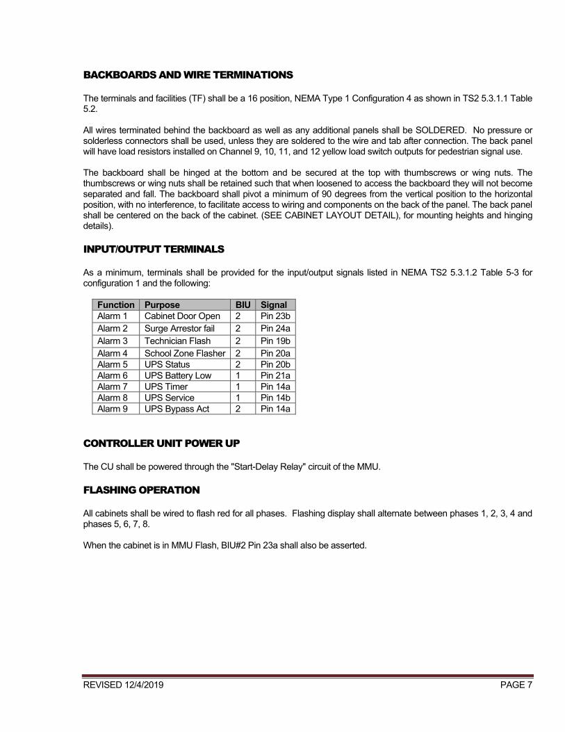
The terminals and facilities (TF) shall be a 16 position, NEMA Type 1 Configuration 4 as shown in TS2 5.3.1.1 Table 5.2. All wires terminated behind the backboard as well as any additional panels shall be SOLDERED. No pressure or solderless connectors shall be used, unless they are soldered to the wire and tab after connection. The back panel will have load resistors installed on Channel 9, 10, 11, and 12 yellow load switch outputs for pedestrian signal use. The backboard shall be hinged at the bottom and be secured at the top with thumbscrews or wing nuts. The thumbscrews or wing nuts shall be retained such that when loosened to access the backboard they will not become separated and fall. The backboard shall pivot a minimum of 90 degrees from the vertical position to the horizontal position, with no interference, to facilitate access to wiring and components on the back of the panel. The back panel shall be centered on the back of the cabinet. (SEE CABINET LAYOUT DETAIL), for mounting heights and hinging details). INPUT/OUTPUT TERMINALS
As a minimum, terminals shall be provided for the input/output signals listed in NEMA TS2 5.3.1.2 Table 5-3 for configuration 1 and the following:
Function Purpose BIU Signal Alarm 1 Cabinet Door Open 2 Pin 23b Alarm 2 Surge Arrestor fail 2 Pin 24a Alarm 3 Technician Flash 2 Pin 19b Alarm 4 School Zone Flasher 2 Pin 20a Alarm 5 UPS Status 2 Pin 20b Alarm 6 UPS Battery Low 1 Pin 21a Alarm 7 UPS Timer 1 Pin 14a Alarm 8 UPS Service 1 Pin 14b Alarm 9 UPS Bypass Act 2 Pin 14a
CONTROLLER UNIT POWER UP
The CU shall be powered through the "Start-Delay Relay" circuit of the MMU. FLASHING OPERATION
All cabinets shall be wired to flash red for all phases. Flashing display shall alternate between phases 1, 2, 3, 4 and phases 5, 6, 7, 8. When the cabinet is in MMU Flash, BIU#2 Pin 23a shall also be asserted.
REVISED 12/4/2019 PAGE 8
DETECTOR RACK
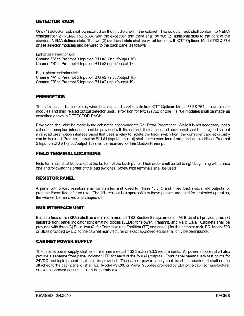
One (1) detector rack shall be installed on the middle shelf in the cabinet. The detector rack shall conform to NEMA configuration 2 (NEMA TS2 5.3.4) with the exception that there shall be two (2) additional slots to the right of the standard NEMA defined slots. The two (2) additional slots shall be wired for use with GTT Opticom Model 762 & 764 phase selector modules and be wired to the back panel as follows: Left phase selector slot: Channel "A" to Preempt 3 Input on BIU #2, (input/output 16) Channel "B" to Preempt 4 Input on BIU #2 (input/output 17) Right phase selector slot: Channel "A" to Preempt 5 Input on BIU #2, (input/output 18) Channel "B" to Preempt 6 Input on BIU #2 (input/output 19) PREEMPTION
The cabinet shall be completely wired to accept and service calls from GTT Opticom Model 762 & 764 phase selector modules and their related optical detector units. Provision for two (2) 762 or one (1) 764 modules shall be made as described above in DETECTOR RACK.
Provisions shall also be made in the cabinet to accommodate Rail Road Preemption. While it is not necessary that a railroad preemption interface board be provided with the cabinet, the cabinet and back panel shall be designed so that a railroad preemption interface panel that uses a relay to isolate the track switch from the controller cabinet circuitry can be installed. Preempt 1 Input on BIU #1 (input/output 14) shall be reserved for rail preemption. In addition, Preempt 2 Input on BIU #1 (input/output 15) shall be reserved for Fire Station Preempt. FIELD TERMINAL LOCATIONS
Field terminals shall be located at the bottom of the back panel. Their order shall be left to right beginning with phase one and following the order of the load switches. Screw type terminals shall be used. RESISTOR PANEL
A panel with 5 load resistors shall be installed and wired to Phase 1, 3, 5 and 7 red load switch field outputs for protected/permitted left turn use. (The fifth resistor is a spare) When these phases are used for protected operation, the wire will be removed and capped off. BUS INTERFACE UNIT
Bus interface units (BIUs) shall as a minimum meet all TS2 Section 8 requirements. All BIUs shall provide three (3) separate front panel indicator light emitting diodes (LEDs) for Power, Transmit, and Valid Data. Cabinets shall be provided with three (3) BIUs: two (2) for Terminals and Facilities (TF) and one (1) for the detector rack. EDI Model 700 or BIU’s provided by EDI to the cabinet manufacturer or exact approved equal shall only be permissible. CABINET POWER SUPPLY
The cabinet power supply shall as a minimum meet all TS2 Section 5.3.5 requirements. All power supplies shall also provide a separate front panel indicator LED for each of the four (4) outputs. Front panel banana jack test points for 24VDC and logic ground shall also be provided. The cabinet power supply shall be shelf mounted. It shall not be attached to the back panel or shelf. EDI Model PS-200 or Power Supplies provided by EDI to the cabinet manufacturer or exact approved equal shall only be permissible.
REVISED 12/4/2019 PAGE 9
FLASH TRANSFER RELAYS
All flash transfer relays shall as a minimum meet NEMA TS2 Section 6 requirements. Only Struther’s Dunn 21XBXPL33-120VAC shall be acceptable. LOAD SWITCHES
EDI Model 510 or Load Switches provided by EDI to the cabinet manufacturer or exact approved equal shall only be permissible. SOLID STATE FLASHERS
EDI Model 810 or Flashers provided by EDI to the cabinet manufacturer or exact approved equal shall only be permissible.
Malfunction Management Unit
ACCEPTABLE MALFUNCTION MANAGEMENT UNIT (MMU) TYPES
All MMUs shall be NEMA TS2 Type 16. EDI MMU2-16LEip with Integral Ethernet port. MMUs provided by EDI to the cabinet manufacturer or exact approved equal shall only be permissible.
Detection
LOOP DETECTOR UNIT
All detector units shall be NEMA Type A per NEMA TS2 6.5.2.2.1. EDI Oracle 2E or exact approved equal.
REVISED 12/4/2019 PAGE 10
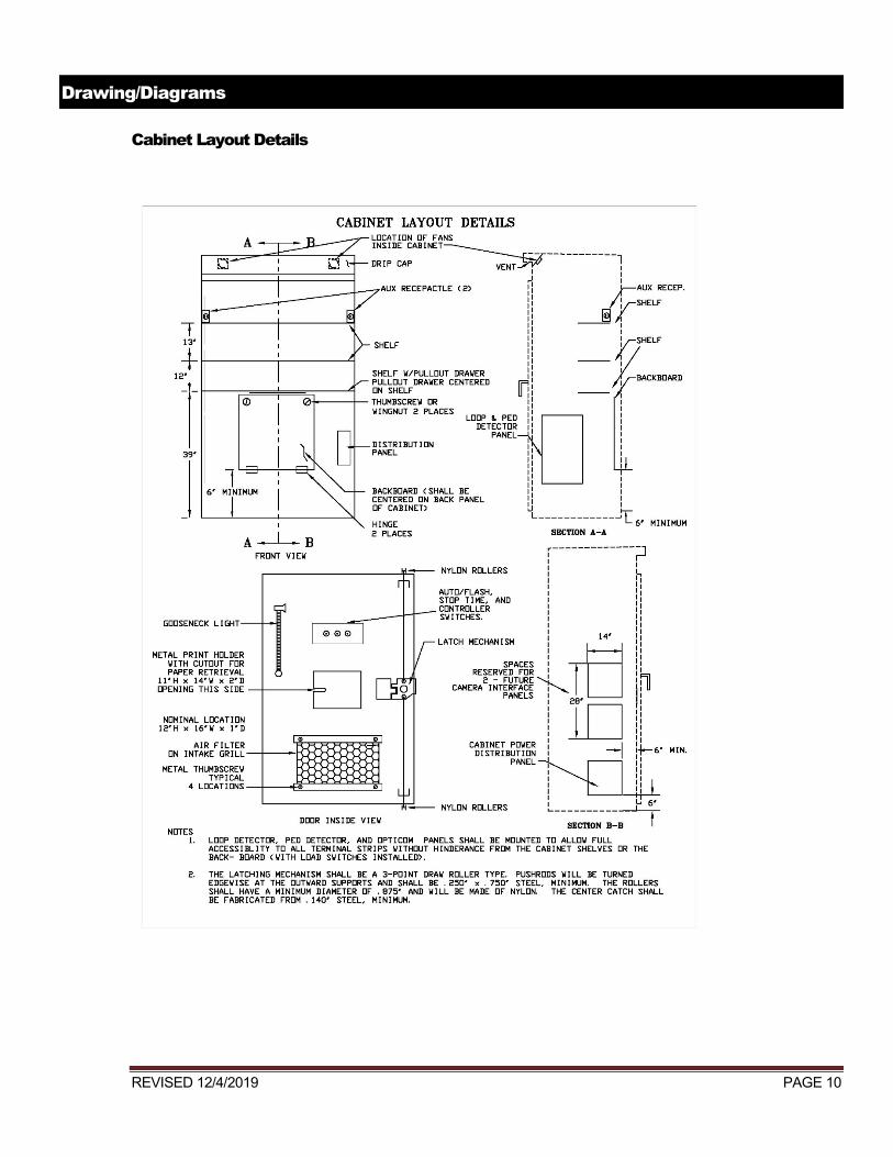
Drawing/Diagrams
Cabinet Layout Details