network applications or principles of network applications · the socket and know with complete...
TRANSCRIPT
2 – Application Layer
1
Maulik Trivedi, CE Department | 2140709 – Computer Networks (CN)
Network Applications OR Principles of Network Applications
A Network application is an application running on one host and provides communication to another application running on a different host.
At the core of network application development is writing programs that run on different end systems and communicate with each other over the network.
In the Web application, there are two distinct programs that communicate with each other: the browser program running in the user's host; and the Web server program running in the Web server host.
Examples of network applications are e-mail web text messaging remote login P2P file sharing multi-user network games streaming stored video (YouTube) voice over IP (e.g., Skype) real-time video conferencing social networking
Network Application Architectures Network Application Architectures
There are two possible structure of applications 1. Client-Server architecture 2. P2P (Peer to Peer) architecture
Client-Server architecture
In a client-server architecture, there is an always-on host, called the server, which provides services requested from many other hosts, called clients.
A classic example is the Web application for which an always-on Web server services requests from browsers running on client hosts. When a Web server receives a request for an object from a client host, it responds by sending the requested object to the client host.
Note that with the client-server architecture, clients do not directly communicate with each other; for example, in the Web application, two browsers do not directly communicate with each other.
Another characteristic of the client-server architecture is that the server has a fixed, well-known address, called an IP address. Because the server is always on, a client can always contact the server by sending a packet to the server’s IP address.
Some of the better-known applications with client-server architecture include the Web, FTP, Telnet, and e-mail.
P2P architecture
In P2P architecture, there is no dedicated server.
Pairs of hosts, called peers communicate directly with each other.

2 – Application Layer
2
Maulik Trivedi, CE Department | 2140709 – Computer Networks (CN)
Because the peers communicate without passing through a dedicated server, the architecture is called peer-to-peer.
Many of today’s most popular and traffic-intensive applications are based on P2P architectures.
Client-Server architecture P2P (Peer to Peer) architecture
Processes Communicating Process
A process is an instance of a program running on a computer or we can say that process is a program under execution.
When processes are running on the same end system, they can communicate with each other with interprocess communication, using rules that are governed by the end system’s operating system.
Processes on two different end systems communicate with each other by exchanging messages across the computer network.
A sending process creates and sends messages into the network; a receiving process receives these messages and possibly responds by sending messages back.
In the context of a communication session between a pair of processes, the process that initiates the communication is called the client. The process that waits to be contacted to begin the session is the server.
The client is a process (program) that sends a message to a server process (program), requesting that the server perform a task (service).
A server is a process (program) that fulfills the client request by performing the task requested by the client. Server programs generally receive requests from client programs, execute it and dispatch responses to client requests.
2 – Application Layer
3
Maulik Trivedi, CE Department | 2140709 – Computer Networks (CN)
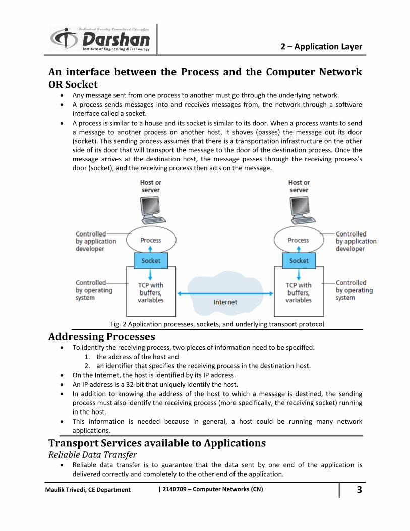
An interface between the Process and the Computer Network OR Socket
Any message sent from one process to another must go through the underlying network.
A process sends messages into and receives messages from, the network through a software interface called a socket.
A process is similar to a house and its socket is similar to its door. When a process wants to send a message to another process on another host, it shoves (passes) the message out its door (socket). This sending process assumes that there is a transportation infrastructure on the other side of its door that will transport the message to the door of the destination process. Once the message arrives at the destination host, the message passes through the receiving process’s door (socket), and the receiving process then acts on the message.
Fig. 2 Application processes, sockets, and underlying transport protocol
Addressing Processes To identify the receiving process, two pieces of information need to be specified:
1. the address of the host and 2. an identifier that specifies the receiving process in the destination host.
On the Internet, the host is identified by its IP address.
An IP address is a 32-bit that uniquely identify the host.
In addition to knowing the address of the host to which a message is destined, the sending process must also identify the receiving process (more specifically, the receiving socket) running in the host.
This information is needed because in general, a host could be running many network applications.
Transport Services available to Applications Reliable Data Transfer
Reliable data transfer is to guarantee that the data sent by one end of the application is delivered correctly and completely to the other end of the application.
2 – Application Layer
4
Maulik Trivedi, CE Department | 2140709 – Computer Networks (CN)
If a protocol provides such a guaranteed data delivery service, it is said to provide reliable data transfer.
One important service that a transport-layer protocol can potentially provide to an application is process-to-process reliable data transfer.
When a transport protocol provides this service, the sending process can just pass its data into the socket and know with complete confidence that the data will arrive without errors at the receiving process.
Throughput Throughput is the rate at which the sending process can deliver bits to the receiving process.
The transport protocol ensures that the available throughput is always at least r bits/sec.
Timing A transport-layer protocol can also provide timing guarantees.
An example guarantee might be that every bit that the sender pumps into the socket arrives at the receiver’s socket no more than 100 msec later. Such a service would be appealing to interactive real-time applications, such as Internet telephony, virtual environments, teleconferencing, and multiplayer games, all of which require tight timing constraints on data delivery in order to be effective.
Security Finally, a transport protocol can provide an application with one or more security services.
For example, in the sending host, a transport protocol can encrypt all data transmitted by the sending process, and in the receiving host, the transport-layer protocol can decrypt the data before delivering the data to the receiving process.
Difference between TCP (Service) and UDP (Service) Description TCP UDP Full Name Transmission Control Protocol User Datagram Protocol
Connection TCP is a connection-oriented protocol.
UDP is a connectionless protocol.
Function A point to point connection is established between client and server before sending a message.
A point to point connection is not established before sending messages.
Usage TCP is suited for applications that require high reliability, and transmission time is relatively less critical.
UDP is suitable for applications that need a fast, efficient transmission, such as games.
Reliability There is an absolute guarantee that the data transferred remains intact and arrives in the same order in which it was sent.
There is no guarantee that the messages or packets sent would reach at all.
Use by other protocols HTTP, HTTPs, FTP, SMTP, Telnet DNS, DHCP, SNMP, RIP, VOIP
The ordering of data packets
TCP rearranges data packets in the order specified.
UDP has no inherent order as all packets are independent of each other.
2 – Application Layer
5
Maulik Trivedi, CE Department | 2140709 – Computer Networks (CN)
Description TCP UDP Speed of transfer The speed for TCP is slower than
UDP. UDP is faster because there is no error-checking for packets.
Header Size TCP header size is 20 bytes UDP Header size is 8 bytes.
Data Flow Control TCP does Flow Control. UDP does not have an option for flow control.
Error Checking TCP does error checking UDP does error checking, but no recovery options.
Acknowledgment Acknowledgment segments No Acknowledgment
Handshake SYN, SYN-ACK, ACK No handshake
The Web and HTTP Web
A Web page consists of objects.
An object is simply a file - such as an HTML file, a JPEG image, a Java applet, or a video clip, that is addressable by a single URL.
Most Web pages consist of a base HTML file and several referenced objects.
For example, if a Web page contains HTML text and five JPEG images, then the Web page has six objects: the base HTML file plus the five images.
The base HTML file references the other objects in the page with the objects’ URLs.
Each URL has two components: the hostname of the server that houses the object and the object’s path name.
For example, the URL “http://www.someSchool.edu/someDepartment/picture.gif” has “www.someSchool.edu” is hostname and “/someDepartment/picture.gif” is a pathname.
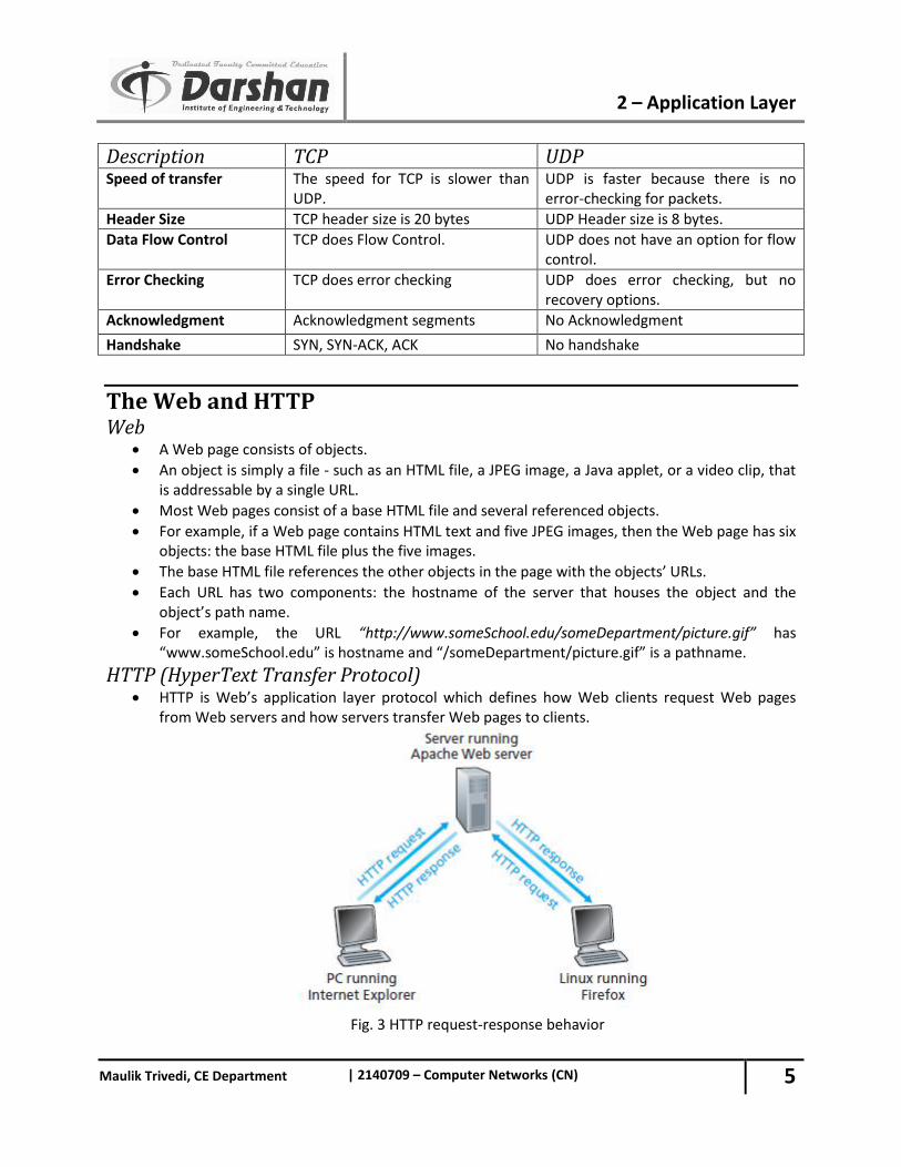
HTTP (HyperText Transfer Protocol) HTTP is Web’s application layer protocol which defines how Web clients request Web pages
from Web servers and how servers transfer Web pages to clients.
Fig. 3 HTTP request-response behavior
2 – Application Layer
6
Maulik Trivedi, CE Department | 2140709 – Computer Networks (CN)
When a user requests a Web page (for example, clicks on a hyperlink), the browser sends HTTP request messages for the objects in the page to the server.
The server receives the requests and responds with HTTP response messages that contain the objects.
HTTP uses TCP as its underlying transport protocol.
The HTTP client first initiates a TCP connection with the server.
Once the connection is established, the browser and the server processes access TCP through their socket interfaces.
HTTP follows client/server model client: a browser that requests, receives, (using HTTP protocol) and "displays" Web objects server: Web server sends (using HTTP protocol) objects in response to requests
HTTP connection types 1. Non-persistent HTTP 2. Persistent HTTP
Non-persistent HTTP
A non-persistent connection is the one that is closed after the server sends the requested object to the client. In other words, the connection is used exactly for one request and one response.
For downloading multiple objects it required multiple connections.
Non-persistent connections are the default mode for HTTP/1.0.
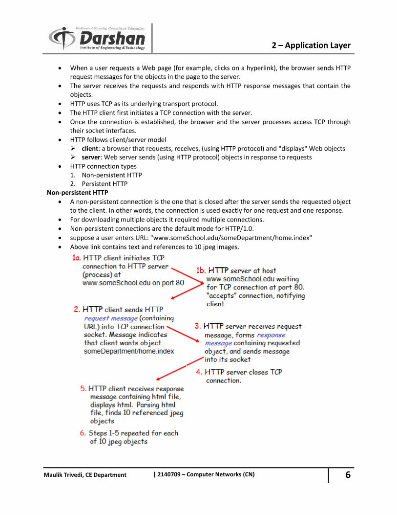
suppose a user enters URL: "www.someSchool.edu/someDepartment/home.index"
Above link contains text and references to 10 jpeg images.

2 – Application Layer
7
Maulik Trivedi, CE Department | 2140709 – Computer Networks (CN)
1. The HTTP client process initiates a TCP connection to the server www.someSchool.edu on port number 80, which is the default port number for HTTP. Associated with the TCP connection, there will be a socket at the client and a socket at the server.
2. The HTTP client sends an HTTP request message to the server via its socket. The request message includes the path name /someDepartment/home.index.
3. The HTTP server process receives the request message via its socket, retrieves the object /someDepartment/home.index from its storage (RAM or disk), encapsulates the object in an HTTP response message, and sends the response message to the client via its socket.
4. The HTTP server process tells TCP to close the TCP connection. (But TCP doesn’t actually terminate the connection until it knows for sure that the client has received the response message intact.).
5. The HTTP client receives the response message. The TCP connection terminates. The message indicates that the encapsulated object is an HTML file. The client extracts the file from the response message, examines the HTML file, and finds references to the 10 JPEG objects.
6. The first four steps are then repeated for each of the referenced JPEG objects.
RTT (Round Trip Time) - which is the time it takes for a small packet to travel from client to server and then back to the client.
Fig. 4 Calculation for the time needed to request and receive an HTML file
2 – Application Layer
8
Maulik Trivedi, CE Department | 2140709 – Computer Networks (CN)
HTTP response time: 1. one RTT to initiate TCP connection 2. one RTT for HTTP request and first few bytes of the HTTP response to return 3. file transmission time
Non-persistent HTTP response time = 2RTT+ file transmission time
It is overhead for each TCP connection. Persistent HTTP
With persistent connections, the server leaves the TCP connection open after sending responses and hence the subsequent requests and responses between the same client and server can be sent.
The server closes the connection only when it is not used for a certain configurable amount of time.
It requires as little as one RTT for all the referenced objects
With persistent connections, the performance is improved by 20%.
Persistent connections are the default mode for HTTP/1.1.
HTTP message format There are two types of HTTP messages:
1. Request 2. Response
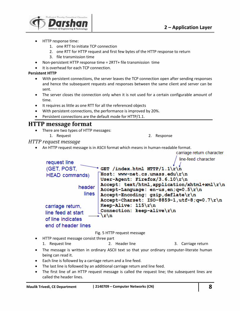
HTTP request message An HTTP request message is in ASCII format which means in human-readable format.
Fig. 5 HTTP request message
HTTP request message consist three part 1. Request line 2. Header line 3. Carriage return
The message is written in ordinary ASCII text so that your ordinary computer-literate human being can read it.
Each line is followed by a carriage return and a line feed.
The last line is followed by an additional carriage return and line feed.
The first line of an HTTP request message is called the request line; the subsequent lines are called the header lines.

2 – Application Layer
9
Firoz A. Sherasiya, CE Department | 2140709 – Computer Networks (CN)
The request line has three fields: the method field, the URL field, and the HTTP version field.
The method field can take on several different values, including getting, POST, HEAD, PUT, and DELETE.
In this example, the browser is requesting the object /somedir/page.html. The version is self-explanatory; in this example, the browser implements version HTTP/1.1.
The header line Host: www.someschool.edu specifies the host on which the object resides.
HTTP response message
Fig. 6 HTTP request message
HTTP response message consist three part 1. Status line 2. Header line 3. Data (Entity body)
The status line has three fields: the protocol version field, a status code, and a corresponding status message.
In this example, the status line indicates that the server is using HTTP/1.1 and that everything is OK.
The Date: header line indicates the time and date when the HTTP response was created and sent by the server.
The Server: header line indicates that the message was generated by an Apache Web server.
The Last-Modified: header line indicates the time and date when the object was created or last modified.
The Content-Length: header line indicates the number of bytes in the object being sent.
The Content-Type: header line indicates that the object in the entity body is HTML text.
User-Server Interaction OR Cookies A small text file created by a Web site that is stored in the user's computer either temporarily
for that session only or permanently on the hard disk (persistent cookie). Cookies provide a way for the Web site to recognize you and keep track of your preferences.

2 – Application Layer
10
Firoz A. Sherasiya, CE Department | 2140709 – Computer Networks (CN)
Cookie technology has four components 1. a cookie header line in the HTTP response message 2. a cookie header line in the HTTP request message 3. a cookie file kept on the user’s end system and managed by the user’s browser 4. a back-end database at the Web site
Fig. 7 keeping user state with cookies
Suppose Susan, access Amazon.com for the first time.
Let us suppose that in the past she has already visited the eBay site.
When the request comes into the Amazon Web server, the server creates a unique identification number and creates an entry in its back-end database by the identification number.
The Amazon Web server then responds to Susan’s browser, including in the HTTP response a set-cookie: header, which contains the identification number.
For example, the header line might be Set-cookie: 1678.
When Susan's browser receives the HTTP response message, it sees the Set-cookie: header.
The browser then appends a line to the special cookie file that it manages.

2 – Application Layer
11
Firoz A. Sherasiya, CE Department | 2140709 – Computer Networks (CN)
This line includes the hostname of the server and the identification number in the Set-cookie: header.
The cookie file already has an entry for eBay, since Susan has visited that site in the past.
As Susan continues to browse the Amazon site, each time she requests a Web page, her browser consults her cookie file, extracts her identification number for this site, and puts a cookie header line that includes the identification number in the HTTP request.
Specifically, each of her HTTP requests to the Amazon server includes the header line: Cookie: 1678.
In this manner, the Amazon server is able to track Susan’s activity at the Amazon site. Use of cookies
authorization shopping carts
recommendations user session state (Web e-mail)
_____________________________________________________________________________________
Web Caching OR Proxy Server A Web cache OR a proxy server is a network entity that satisfies HTTP requests on the behalf of
an origin Web server.
The Web cache has its own disk storage and keeps copies of recently requested objects in this storage.
Fig. 8 Clients requesting objects through a Web cache
A Web cache OR a proxy server is a network entity that satisfies HTTP requests on the behalf of an origin Web server.
The Web cache has its own disk storage and keeps copies of recently requested objects in this storage.
A user’s browser can be configured so that all of the user’s HTTP requests are first directed to the Web cache.
As an example, suppose a browser is requesting the object http://www.someschool.edu/campus.gif.
Here is what happens 1. The browser establishes a TCP connection to the Web cache and sends an HTTP request
for the object to the Web cache.
2 – Application Layer
12
Firoz A. Sherasiya, CE Department | 2140709 – Computer Networks (CN)
2. The Web cache checks to see if it has a copy of the object stored locally. If it does, the Web cache returns the object within an HTTP response message to the client browser.
3. If the Web cache does not have the object, the Web cache opens a TCP connection to the origin server, that is, to www.someschool.edu. The Web cache then sends an HTTP request for the object into the cache-to-server TCP connection. After receiving this request, the origin server sends the object within an HTTP response to the Web cache.
4. When the Web cache receives the object, it stores a copy in its local storage and sends a copy, within an HTTP response message, to the client browser.
Note that a cache is both a server and a client at the same time.
When it receives requests from and sends responses to a browser, it is a server.
When it sends requests to and receives responses from an origin server, it is a client. Why Web caching is needed (Required)? OR Advantages of Caching
To reduce response time for a client request To reduce traffic on an institution’s access link To enable "poor" content providers to effectively deliver content
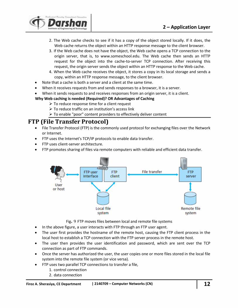
FTP (File Transfer Protocol) File Transfer Protocol (FTP) is the commonly used protocol for exchanging files over the Network
or Internet. FTP uses the Internet's TCP/IP protocols to enable data transfer. FTP uses client-server architecture. FTP promotes sharing of files via remote computers with reliable and efficient data transfer.
Fig. 9 FTP moves files between local and remote file systems
In the above figure, a user interacts with FTP through an FTP user agent.
The user first provides the hostname of the remote host, causing the FTP client process in the local host to establish a TCP connection with the FTP server process in the remote host.
The user then provides the user identification and password, which are sent over the TCP connection as part of FTP commands.
Once the server has authorized the user, the user copies one or more files stored in the local file system into the remote file system (or vice versa).
FTP uses two parallel TCP connections to transfer a file, 1. control connection 2. data connection
2 – Application Layer
13
Firoz A. Sherasiya, CE Department | 2140709 – Computer Networks (CN)
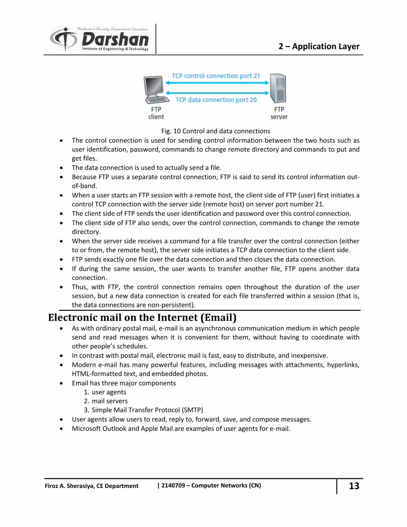
Fig. 10 Control and data connections
The control connection is used for sending control information between the two hosts such as user identification, password, commands to change remote directory and commands to put and get files.
The data connection is used to actually send a file.
Because FTP uses a separate control connection, FTP is said to send its control information out-of-band.
When a user starts an FTP session with a remote host, the client side of FTP (user) first initiates a control TCP connection with the server side (remote host) on server port number 21.
The client side of FTP sends the user identification and password over this control connection.
The client side of FTP also sends, over the control connection, commands to change the remote directory.
When the server side receives a command for a file transfer over the control connection (either to or from, the remote host), the server side initiates a TCP data connection to the client side.
FTP sends exactly one file over the data connection and then closes the data connection.
If during the same session, the user wants to transfer another file, FTP opens another data connection.
Thus, with FTP, the control connection remains open throughout the duration of the user session, but a new data connection is created for each file transferred within a session (that is, the data connections are non-persistent).
Electronic mail on the Internet (Email) As with ordinary postal mail, e-mail is an asynchronous communication medium in which people
send and read messages when it is convenient for them, without having to coordinate with other people’s schedules.
In contrast with postal mail, electronic mail is fast, easy to distribute, and inexpensive.
Modern e-mail has many powerful features, including messages with attachments, hyperlinks, HTML-formatted text, and embedded photos.
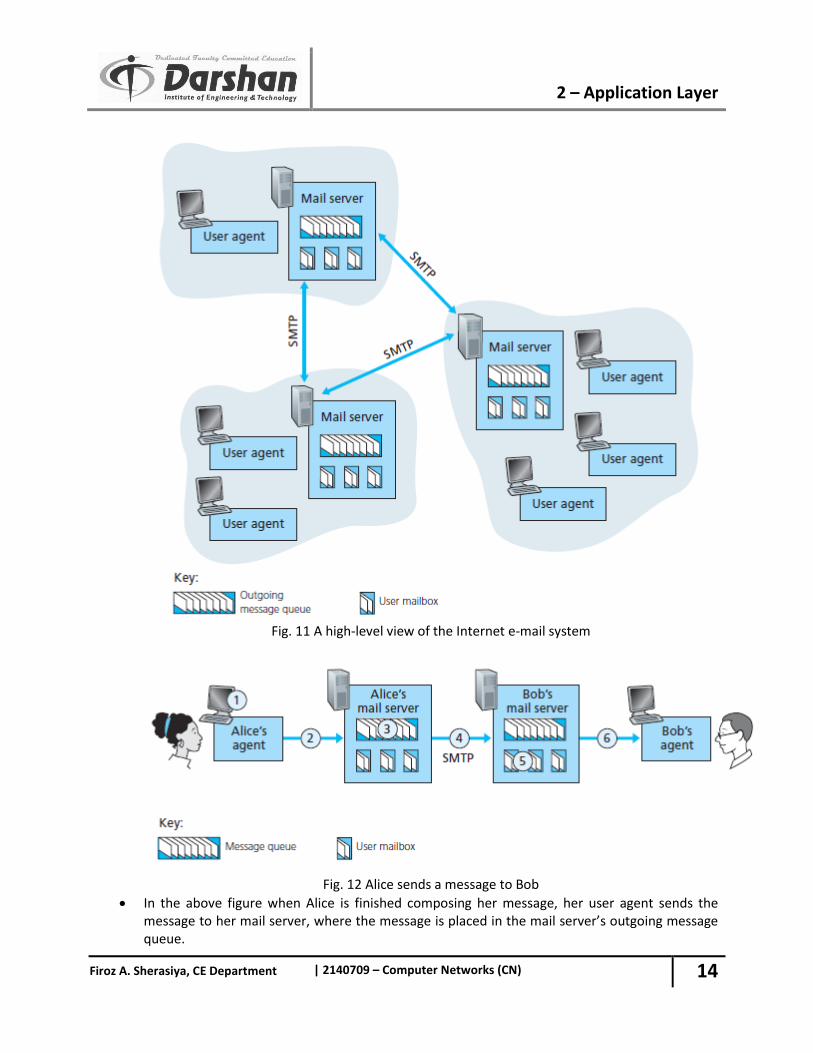
Email has three major components 1. user agents 2. mail servers 3. Simple Mail Transfer Protocol (SMTP)
User agents allow users to read, reply to, forward, save, and compose messages.
Microsoft Outlook and Apple Mail are examples of user agents for e-mail.
2 – Application Layer
14
Firoz A. Sherasiya, CE Department | 2140709 – Computer Networks (CN)
Fig. 11 A high-level view of the Internet e-mail system
Fig. 12 Alice sends a message to Bob
In the above figure when Alice is finished composing her message, her user agent sends the message to her mail server, where the message is placed in the mail server’s outgoing message queue.

2 – Application Layer
15
Firoz A. Sherasiya, CE Department | 2140709 – Computer Networks (CN)
When Bob wants to read a message, his user agent retrieves the message from his mailbox in his mail server.
Mail servers form the core of the e-mail infrastructure.
Each recipient, such as Bob, has a mailbox located in one of the mail servers.
Bob’s mailbox manages and maintains the messages that have been sent to him.
A typical message starts its journey in the sender’s user agent, travels to the sender’s mail server and travels to the recipient’s mail server, where it is deposited in the recipient’s mailbox.
When Bob wants to access the messages in his mailbox, the mail server containing his mailbox authenticates Bob (with usernames and passwords).
Alice’s mail server must also deal with failures in Bob’s mail server.
If Alice’s server cannot deliver mail to Bob’s server, Alice’s server holds the message in a message queue and attempts to transfer the message later.
Reattempts are often done every 30 minutes or so; if there is no success after several days, the server removes the message and notifies the sender (Alice) with an e-mail message.
SMTP is the principal application-layer protocol for Internet electronic mail. It uses the reliable data transfer service of TCP to transfer mail from the sender’s mail server to the recipient’s mail server.
SMTP has two sides: a client side, which executes on the sender’s mail server, and a server side, which executes on the recipient’s mail server.
Both the client and server sides of SMTP run on every mail server.
When a mail server sends mail to other mail servers, it acts as an SMTP client. When a mail server receives mail from other mail servers, it acts as an SMTP server.
SMTP (Simple Mail Transfer Protocol) SMTP transfers messages from senders’ mail servers to the recipients’ mail servers.
It restricts the body (not just the headers) of all mail messages to simple 7-bit ASCII.
To illustrate the basic operation of SMTP, let’s take a common scenario. Suppose Alice wants to send Bob a simple ASCII message.
Fig. 13 Alice sends a message to Bob
1. Alice invokes her user agent for e-mail, provides Bob’s e-mail address (for example, [email protected]), composes a message and instructs the user agent to send the message.
2 – Application Layer
16
Firoz A. Sherasiya, CE Department | 2140709 – Computer Networks (CN)
2. Alice’s user agent sends the message to her mail server, where it is placed in a message queue.
3. The client side of SMTP, running on Alice’s mail server, sees the message in the message queue. It opens a TCP connection to an SMTP server, running on Bob’s mail server.
4. After some initial SMTP handshaking, the SMTP client sends Alice’s message into the TCP connection.
5. At Bob’s mail server, the server side of SMTP receives the message. Bob’s mail server then places the message in Bob’s mailbox.
6. Bob invokes his user agent to read the message at his convenience.
SMTP does not normally use intermediate mail servers for sending mail, even when the two mail servers are located at opposite ends of the world.
If Bob’s mail server is down, the message remains in Alice’s mail server and waits for a new attempt and the message does not get placed in some intermediate mail server.
How SMTP transfers a message from a sending mail server to a receiving mail server
First, the client SMTP (running on the sending mail server host) has TCP establish a connection to port 25 at the server SMTP (running on the receiving mail server host).
If the server is down, the client tries again later.
Once this connection is established, the server and client perform some application-layer handshaking, just as humans often introduce themselves before transferring information from one to another.
During this SMTP handshaking phase, the SMTP client indicates the e-mail address of the sender (the person who generated the message) and the e-mail address of the recipient.
Once the SMTP client and server have introduced themselves to each other, the client sends the message.
SMTP can count on the reliable data transfer service of TCP to get the message to the server without errors.
The client then repeats this process over the same TCP connection if it has other messages to send to the server; otherwise, it instructs TCP to close the connection.
Comparison of SMTP with HTTP HTTP is mainly a pull protocol-someone loads information on a web server and users use HTTP
to pull the information from the server. On the other hand, SMTP is primarily a push protocol-the sending mail server pushes the file to receive mail server.
SMTP requires each message, including the body of each message, to be in seven-bit ASCII format. If the message contains binary data, then the message has to be encoded into seven-bit ASCII format. HTTP does not have this restriction.
HTTP encapsulate each object of a message in its own response message while SMTP places all of the message's objects into one message.
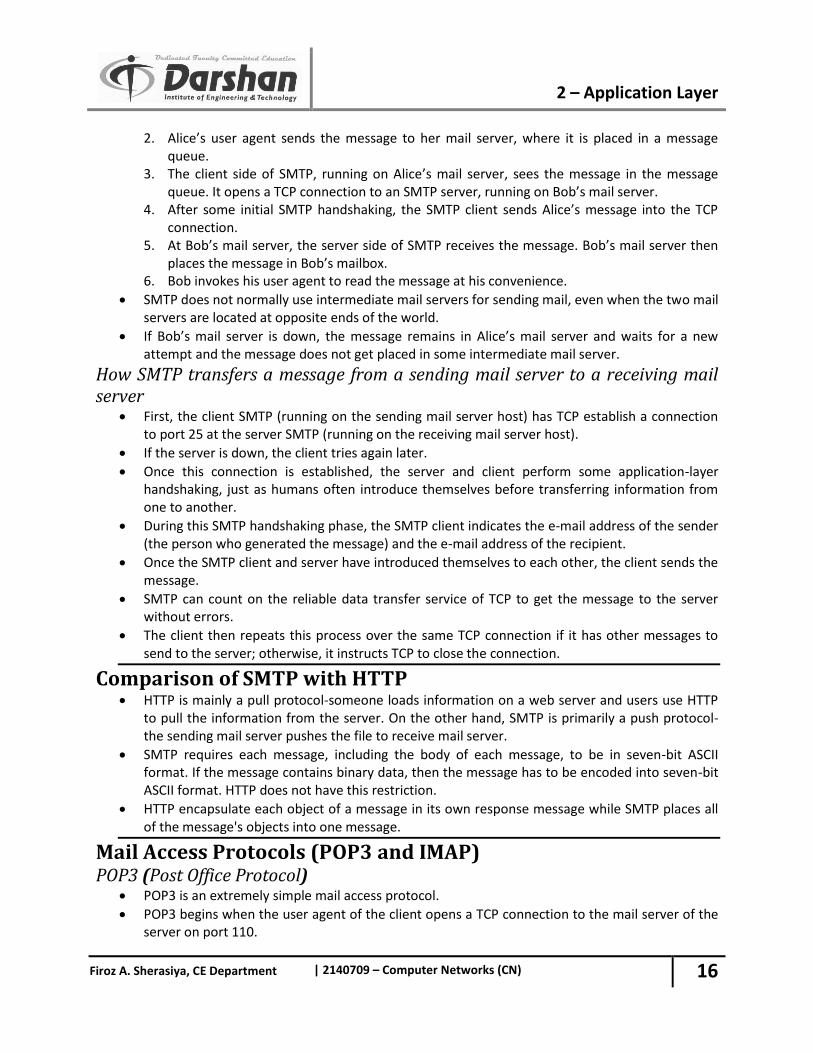
Mail Access Protocols (POP3 and IMAP) POP3 (Post Office Protocol)
POP3 is an extremely simple mail access protocol.
POP3 begins when the user agent of the client opens a TCP connection to the mail server of the server on port 110.

2 – Application Layer
17
Firoz A. Sherasiya, CE Department | 2140709 – Computer Networks (CN)
With the TCP connection established, POP3 progresses through three phases: authorization, transaction, and update.
During the first phase, authorization, the user agent sends a username and a password to authenticate the user.
During the second phase, transaction, the user agent retrieves messages; also during this phase, the user agent can mark messages for deletion, remove deletion marks and obtain mail statistics.
The third phase, update, occurs after the client has issued the quit command, ending the POP3 session; at this time, the mail server deletes the messages that were marked for deletion.
POP3 is designed to delete mail on the server as soon as the user has downloaded it.
However, some implementations allow users or an administrator to specify that mail is saved for some period of time. POP can be thought of as a "store-and-forward" service.
IMAP (Internet Message Access Protocol) With POP3 access, once a receiver has downloaded his messages to the local machine, he can
create mail folders and move the downloaded messages into the folders.
A receiver can then delete messages, move messages across folders, and search for messages (by sender name or subject).
But this paradigm—namely, folders and messages in the local machine—poses a problem for the roaming user, who would prefer to maintain a folder hierarchy on a remote server that can be accessed from any computer.
This is not possible with POP3—the POP3 protocol does not provide any means for a user to create remote folders and assign messages to folders.
An IMAP server will associate each message with a folder; when a message first arrives at the server, it is associated with the recipient’s INBOX folder.
The recipient can then move the message into a new, user-created folder, read the message, delete the message, and so on.
The IMAP protocol provides commands to allow users to create folders and move messages from one folder to another.
IMAP also provides commands that allow users to search remote folders for messages matching specific criteria.
Another important feature of IMAP is that it has commands that permit a user agent to obtain components of messages. For example, a user agent can obtain just the message header of a message or just one part of a multipart MIME message.
This feature is useful when there is a low-bandwidth connection (for example, a slow-speed modem link) between the user agent and its mail server.
With a low bandwidth connection, the user may not want to download all of the messages in its mailbox, particularly avoiding long messages that might contain, for example, an audio or video clip.
DNS (Domain Name System) DNS (Domain Name System) is an internet service that translates domain names into IP
addresses.
Because domain names are alphabetic, they're easier to remember for a human being but The Internet is really based on IP addresses.
2 – Application Layer
18
Firoz A. Sherasiya, CE Department | 2140709 – Computer Networks (CN)
Every time you use a domain name, therefore, a DNS service must translate the domain name into the corresponding IP address. For example, the domain name www.google.com might translate to 198.105.232.4.
The DNS system is, in fact, its own network. If one DNS server doesn't know how to translate a particular domain name, it asks another one, and so on, until the correct IP address is returned.
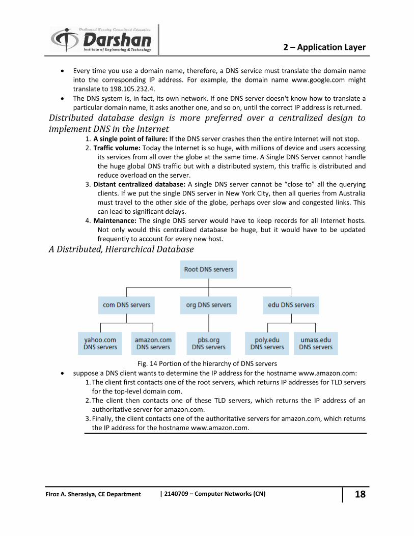
Distributed database design is more preferred over a centralized design to implement DNS in the Internet
1. A single point of failure: If the DNS server crashes then the entire Internet will not stop. 2. Traffic volume: Today the Internet is so huge, with millions of device and users accessing
its services from all over the globe at the same time. A Single DNS Server cannot handle the huge global DNS traffic but with a distributed system, this traffic is distributed and reduce overload on the server.
3. Distant centralized database: A single DNS server cannot be “close to” all the querying clients. If we put the single DNS server in New York City, then all queries from Australia must travel to the other side of the globe, perhaps over slow and congested links. This can lead to significant delays.
4. Maintenance: The single DNS server would have to keep records for all Internet hosts. Not only would this centralized database be huge, but it would have to be updated frequently to account for every new host.
A Distributed, Hierarchical Database
Fig. 14 Portion of the hierarchy of DNS servers
suppose a DNS client wants to determine the IP address for the hostname www.amazon.com: 1. The client first contacts one of the root servers, which returns IP addresses for TLD servers
for the top-level domain com. 2. The client then contacts one of these TLD servers, which returns the IP address of an
authoritative server for amazon.com. 3. Finally, the client contacts one of the authoritative servers for amazon.com, which returns
the IP address for the hostname www.amazon.com.
2 – Application Layer
19
Firoz A. Sherasiya, CE Department | 2140709 – Computer Networks (CN)
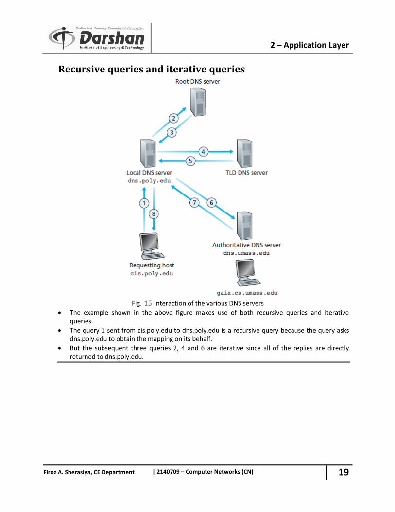
Recursive queries and iterative queries
Fig. 15 Interaction of the various DNS servers
The example shown in the above figure makes use of both recursive queries and iterative queries.
The query 1 sent from cis.poly.edu to dns.poly.edu is a recursive query because the query asks dns.poly.edu to obtain the mapping on its behalf.
But the subsequent three queries 2, 4 and 6 are iterative since all of the replies are directly returned to dns.poly.edu.