network on chip test methodology - koreatest.or.kr · noc basics noc related ... “dependable...
TRANSCRIPT

1
Network On Chip Test Methodology
Hong-Sik Kim2009.6.24.

2
Topics
IntroductionNoC basicsNoC related research topicsStudy on reliability and testability of NoCConclusions

3
Design Paradigm Shift

4
Advances in IC Design Methodologies

5
Interconnect Delay
•Interconnect Delay Dominates Gate Delay
▪ Global interconnect delay is being continuously increasing▪Multiple clock cycles to cross chip die is required▪ Performance limitation

6
W.J. Dally presentation: Computer architecture is all about interconnect (it is now and it will be more so in 2010) HPCA Panel February 4, 2002
Operation Delay
0.13um 50nm
32b ALU Operation 650 ps 250 ps
32b Register Read 325 ps 125 ps
Read 32 b from 8KB RAM 780 ps 300 ps
Transfer 32b across chip (10 mm) 1400 ps 2300 ps
Transfer 32b across chip (200 mm) 2800 ps 4600 ps
Interconnect Delay
•Ratio between global communication delay and operational delay
▪ 2 : 1 in 2002▪ 9 : 1 in 2010
7
Noise in DSM
• Source of Noise
▪ Crosstalk▪ Power supply noise▪ Substrate noise▪ Soft errors▪ EMI▪ Thermal noise
• DSM technology
▪ very subtle to noise effect▪ low operating voltage, high clock frequency▪ increased coupling cap

8
Noise in DSM
• Crosstalk fault
▪ Noise on a wire is included by the switching activities on neighboring wires▪ Due to the capacitive coupling between the adjacent wires▪ Results in propagation delay or glitch
w s
tCcouple Ccouple
Ccouple ∝ t/s
▪ Ccouple depends on technology parameters and transition directions▪With technology scaling, wire spacing is shrinking faster than wire height
GND
Cground

9
Noise in DSM
• Crosstalk Delay Faults
Ccouple
▪When the transition of adjacent signals in opposite directions, the delay is longest.Ctotal = 2Ccouple + 2Ccouple + Cground
Ccouple

10
Noise in DSM
• Crosstalk Analysis
▪ Different transmission patterns have different Ctotal, and then have different delay
Ctotal Patterns
0
− − −
− −↑ − −↓ ↑ − − ↓− −
↑ −↑ ↑−↓ ↓−↑ ↓−↓
Cground ↑↑↑ ↓↓↓
Ccouple+Cground −↑↑ −↓↓ ↑↑− ↓↓−
2Ccouple+Cground−↑− −↓−
↑↑↓ ↑↓↓ ↓↑↑ ↓↓↑
3Ccouple+Cground −↓↑ −↓↑ ↑↓− ↓↑−
4Ccouple+Cground ↑↓↑ ↓↑↓
P. Sotiriadis et al, “Reducing bus delay in submicron technology using coding”, ASP-DAC, 2001

11
How to address reliability problems in DSM Tech.
• High Noise Probability in DSM Technology
▪ SoC will operate in the presence of noise due to crosstalk, EMI, soft error etc▪ Data may be delayed or corrupted▪Malfunction is modeled as single/multiple upsets
▪ Present design reduces noise by physical design▪ Future design will tolerate noise by pushing solutions to higher abstraction levels

12
Communication Centric Application
• Many Core Processor
▪ For massive multi-media application▪ Need for low power consumption and reliable data communication
• Mile Stone
▪ 2001 : p960 Regatta by IBM▪ 2005 : ARM11 MPCore, MPSoC▪ 2007 : Tile64 Multi-Core Processor by Tilera▪ 2009 : Larabee scheduled by INTEL
• Features in terms of interconnect
▪ Very communication centric core▪ Need for scalability of global communication
13
Communication Centric Application
core core
Bridge corecore core
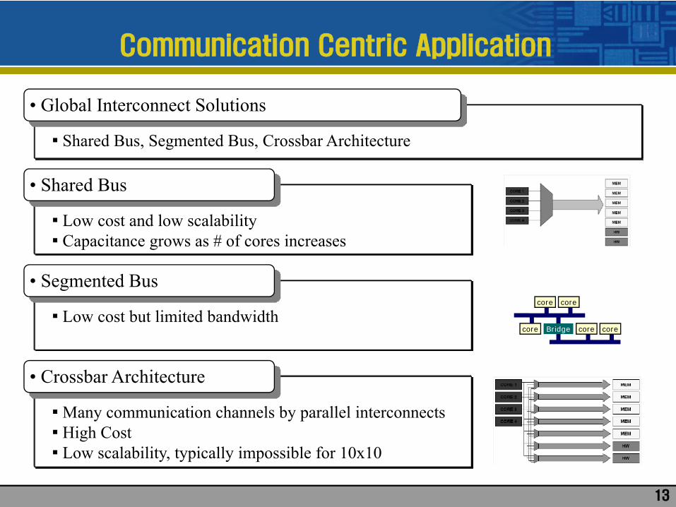
• Global Interconnect Solutions
▪ Shared Bus, Segmented Bus, Crossbar Architecture
• Shared Bus
▪ Low cost and low scalability▪ Capacitance grows as # of cores increases
• Segmented Bus
▪ Low cost but limited bandwidth
• Crossbar Architecture
▪Many communication channels by parallel interconnects▪ High Cost▪ Low scalability, typically impossible for 10x10

14
New Solution : Network on Chip Design
• Technology Aspect
▪ Need for reliable high performance global data transfer▪ Need for reliable global communication against DSM noise
• Product Aspect
▪Many-Core processor application requires communication centric design▪ Previous solutions cannot provide enough scalability and bandwidth
• Network on Chip Design Methodology
▪An evolution of on-chip bus interconnect technology▪ Interconnection model implemented on a chip in the form of a micro-network
- High performance, scalability and reliability- Affordable cost- High complexity

15
Network on Chip Basics
• High Flexibility in Topology and Routing Policy
▪ Various topology▪ Resource constrained router preferable
• NoC Components
▪ IP Core▪ Network Adaptor
- Connects between IP core and router▪ Routing Node
- Switch and routing table▪ Link
- Wires connecting nodes
16
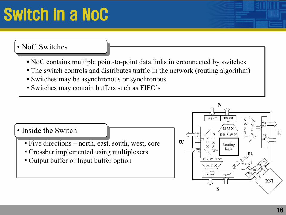
Switch in a NoC
• NoC Switches
▪ NoC contains multiple point-to-point data links interconnected by switches▪ The switch controls and distributes traffic in the network (routing algorithm)▪ Switches may be asynchronous or synchronous▪ Switches may contain buffers such as FIFO’s
▪ Five directions – north, east, south, west, core▪ Crossbar implemented using multiplexers▪ Output buffer or Input buffer option
• Inside the Switch

17
On-Chip Bus VS Network on Chip
18
R
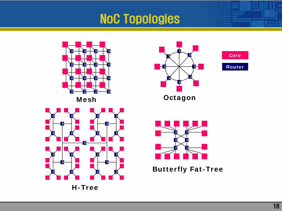
Mesh
R R R
R R R R
R R R R
R R R R
Butterfly Fat-Tree
R
RR
R
RR
Octagon
R RR
R
RR
R
R
Core
Router
R R
R R
R
R
R
R
R
R
R
R R
R R
R
R
R
R
R
R
H-Tree
NoC Topologies

19
NoC Structures
• Regular topology NoC
▪ From multi-computer networks▪ Designed for general and homogeneous systems▪ NoC flatform design

20
• Application specific NoC
▪ Customized NoC for each application results in significant performance improvement▪ Irregular-topology and hierarchy▪ For both homogeneous and heterogeneous systems
NoC Structures

21
• NOSTRUM
▪ 2D mesh topology▪ 128 bit wide link▪ Non-minimal adaptive hot potato routing▪ No buffering▪ Best effort, guaranteed latency virtual channels
NoC Examples

22
• Æthereal (Phillips)
▪ Unkown, probably low dimensional tree or mesh▪ Deterministic source based routing▪ Provides both guaranteed traffic and best effort service▪ Input buffering▪ 6 port router (32 bit word size)
NoC Examples

23
NoC Examples
• SPIN
▪ Fat tree topology▪Wormhole switching▪Adaptive routing▪ Input buffering▪ bidirectional 32 bit links

24
NoC Examples
• Octagon(UCSD)
▪ Basic 8 node architecture▪ 2 hop diameter▪ source based routing▪

25
• XPIPES (Stanford Univ.)
▪ Heterogeneous NoC▪ Source based routing▪Wormhole switching▪ Long, pipeleined links▪ Output buffering▪ Virtual channel▪Acknowledgement based flow control with retransmission
NoC Examples

26
• Cell Processor
▪ High performance heterogeneous media chip▪ EIB (element interconnect bus) based on chip network
NoC Commercial Products
• Larabee (Intel)
▪Many-core GPU▪ Ring bus network based inter-processor communication

27
• Tile64 (Tilera)
▪ Based on MIT Raw Processor▪ 64 identical GP core included▪ 3 way VLIW pipeline▪ on-chip iMesh network▪ 5 2D mesh networks▪ Each link consists of 2 unidirectional 32 bit link▪ wormhole routing▪ 31 Tbps network throughput
NoC Commercial Products

28
NoC Design Flow

29
NoC Research Issues
• DFT methodology• Test scheduling
• Fault tolerant design

30
Fault Tolerant Design
• Hardware Failure Taxonomy
Failure
Permanent Temporary
defects, wearout, design failure,out of parameters
Transient Intermittentsoft error, EMI, substrate noise
gradual degradation,weak part
To test and tolerate
To tolerate

31
Fault Tolerant Design
• FT for transient faults
▪ Software layer is responsible and recoverable▪ Link-to-link or end-to-end re-transmission▪ Error detection and correction (for example CRC)▪ ED/EC and retransmission
• FT for permanent faults
▪ System should avoid using the faulty module▪ On-line or production test be prerequisite

32
Fault Tolerant Design
• NOC FT
▪Yield improvement▪ Reliable data communication against noise
•CFC based FT
▪ Crosstalk free coding algorithm▪ Reducing total cap comparable with shielded case by encoding data
•FT Routing
▪ Flooding▪ ECC and Re-transmission

33
Crosstalk Free Coding
• CFC Algorithm
▪ Forbidden pattern free coding (010, 101)▪ Forbidden transition free coding▪ Reduce the total cap into 2Ccouple + Cground
C. Duan et al, “Forbidden transition free crosstalk avoidance CODEC design”, DAC, 2008
encoder
Original datam bits
decoder
w bits
m bits
Physical channel

34
FT Routing Algorithm
• Flooding based FT
▪ Probabilistic flooding▪ Directed flooding▪ Redundant Random Walk
M. Pirretti et al, “Fault tolerant algorithms for network onchip interconnect”, IEEE annual symposium on VLSIemerging trends in VLSI systems design, 2004
D
p
datadata
data
data
D
p
datadata
D
pe pw ps pn
data
35
FT Routing Algorithm
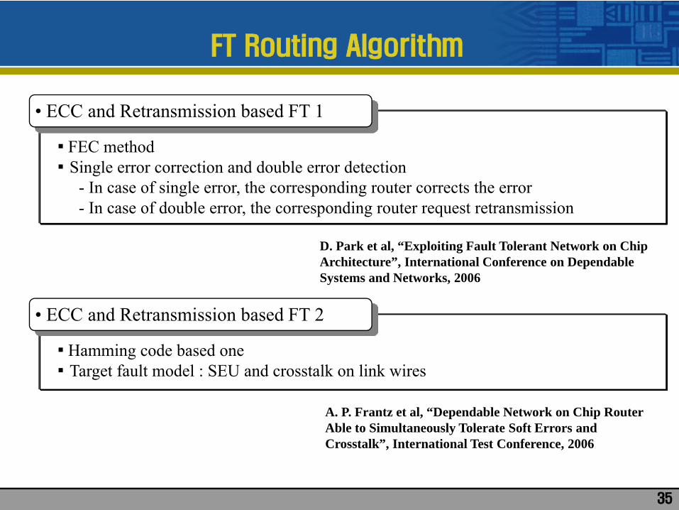
• ECC and Retransmission based FT 1
▪ FEC method▪ Single error correction and double error detection
- In case of single error, the corresponding router corrects the error- In case of double error, the corresponding router request retransmission
D. Park et al, “Exploiting Fault Tolerant Network on Chip Architecture”, International Conference on Dependable Systems and Networks, 2006
• ECC and Retransmission based FT 2
▪ Hamming code based one▪ Target fault model : SEU and crosstalk on link wires
A. P. Frantz et al, “Dependable Network on Chip Router Able to Simultaneously Tolerate Soft Errors and Crosstalk”, International Test Conference, 2006

36
FT Routing Algorithm
• Retransmission Policy
▪ Retransmission policy- E2E : error check is performed at the end point
: power consumption reduced: in case of destination header error, additional network traffic occurs
- S2S: error check is done at every hop: power consumption increased: in case of high error rate, network latency guaranteed
End to End Switch to Switch

37
NoC Testing
• How to test NoC
▪ IP core test- tested as SoC cores- NoC network resource can be reused as TAM
▪ Router and link test- Wrapper based structural test- On-line functional test by error checker- BIST (built-in self test)- Functional test

38
NoC Testing
• NoC Test Model
▪ Network as TAM▪ Test wrapper to isolate cores during test mode▪ Packet based test delivery
core core core core
NoC
ATE
Wrapper
Head
Test head
flit0
flit1
flit2
Tail
CUT
0000
000101100111
Flit0 = 000010Flit1 = 101101Flit2 = 1000xx
W bitsW bitsTest channel = 2W

39
NoC Testing
• Test Channels and Cost
core core core core
NoC
ATEW bitsW bits
Test channel = 2W
core core core core
NoC
ATE2W bits2W bits
Test channel = 4W

40
P93791 - Test time and ATE cost
0
50000
100000
150000
200000
250000
300000
350000
400000
450000
3/3 4/4 5/5 6/6
Test ports configuration: #INPUTS / #OUTPUT PORTS
Test
tim
e
0
50
100
150
200
250
300
350
400
450
Num
ber
of A
TE
chan
nels
NoC Testing
• Test Channels and Cost
# of test channelstest time

41
NoC Testing
J. Dalmasso et al, “Fitting ATE Channels with Scan Chains: a Comparison between a Test Data Compression Technique and Serial Loading of Scan Chains”, DELTA, 2006
▪ Limited test channel reduce the test parallelism ▪ Test compression can increase the number of cores under parallel testing▪ So results in test application time reduction or test cost reduction
• Test Compression Application for Test Cost Reduction
core
sourceTest input
decoder
M
W
core
sourceTest output
encoderM
W
W

42
NoC Testing
• Test Compression Application for Test Cost Reduction
packet header
test header
01101
tail
01101
01110
Original Test PacketW=5 bits header
test header
01
tail
10
11
header
test header
01
Compressed Test PacketM=2 bits
packet header
test header
01101
tail
01101
01110
Decoded Test PacketW=5 bits
ATE CUT

43
NoC Testing
▪ Experimental Results▪ 33% test time reduction for d695 benchmark circuits
• Test Compression Application for Test Cost Reduction
For d695, 32 bit test channel assumed
System Configuration Test Time
1 32-bit test input 36588 cycles
3 inputs of 12, 10, and 10 bits 24395 cycles
J. Dalmasso et al, “Fitting ATE Channels with Scan Chains: a Comparison between a Test Data Compression Technique and Serial Loading of Scan Chains”, DELTA, 2006

44
NoC Testing
▪ Test scheduling with dedicated path▪ Each core associated with a routing path▪ Test pipeline maintained
• NoC Test Scheduling Algorithm
E. Cota et al, “Improving NoC based Testing”, NoC workshop, 2007
Define test packet
Define path for each core
Select a packet
Find available
path
Schedule packet
Sort packet accordingto test time
Select schedule forminimum total test time

45
NoC Testing
▪An simple example
• NoC Test Scheduling Algorithm
Out
Out
2
3
5 10
6 4
1
79 8
In
In
Out
10
12
6 5 4 8 10 7 3 2 1 9Test pattern set
▪ d695, test channel = 32 bits▪ 3 inputs with 10, 10, 12 bits
• Test Info.
10

46
NoC Testing
▪An simple example
• NoC Test Scheduling Algorithm
Out
Out
2
3
5 10
6 4
1
79 8
In
In
Out
10
12
6 5 4 8 10 7 3 2 1 9Test pattern set
98696
108566
108566
10

47
NoC Testing
▪An simple example
• NoC Test Scheduling Algorithm
Out
Out
2
3
5 10
6 4
1
79 8
In
In
Out
10
12
6 5 4 8 10 7 3 2 1 9Test pattern set
98696
10

48
NoC Testing
▪An simple example
• NoC Test Scheduling Algorithm
Out
Out
2
3
5 10
6 4
1
79 8
In
In
Out
10
12
6 5 4 8 10 7 3 2 1 9Test pattern set
98696
10
154595
68265
68505

49
NoC Testing
▪An simple example
• NoC Test Scheduling Algorithm
Out
Out
2
3
5 10
6 4
1
79 8
In
In
Out
10
12
6 5 4 8 10 7 3 2 1 9Test pattern set
98696
1068265

50
NoC Testing
▪An simple example
• NoC Test Scheduling Algorithm
Out
Out
2
3
5 10
6 4
1
79 8
In
In
Out
10
12
6 5 4 8 10 7 3 2 1 9Test pattern set
98696
1068265
126554
58294
151154

51
NoC Testing
▪An simple example
• NoC Test Scheduling Algorithm
Out
Out
2
3
5 10
6 4
1
79 8
In
In
Out
10
12
Test pattern set
98696
1068265
58294
6 5 4 8 10 7 3 2 1 9

52
NoC Testing
▪An simple example
• NoC Test Scheduling Algorithm
Out
Out
2
3
5 10
6 4
1
79 8
In
In
Out
10
12
Test pattern set
98696
1068265
58294
104348
114318
140138
6 5 4 8 10 7 3 2 1 9

53
NoC Testing
▪An simple example
• NoC Test Scheduling Algorithm
Out
Out
2
3
5 10
6 4
1
79 8
In
In
Out
10
12
Test pattern set
98696
1068265
58294
104348
6 5 4 8 10 7 3 2 1 9
1006910

54
NoC Testing
▪An simple example
• NoC Test Scheduling Algorithm
Out
Out
2
3
5 10
6 4
1
79 8
In
In
Out
10
12
Test pattern set
98696
1068265
58294
104348
6 5 4 8 10 7 3 2 1 9
1006910
133287

55
NoC Testing
▪An simple example
• NoC Test Scheduling Algorithm
Out
Out
2
3
5 10
6 4
1
79 8
In
In
Out
10
12
Test pattern set
98696
1068265
58294
104348
6 5 4 8 10 7 3 2 1 9
1006910
133287
125763

56
NoC Testing
▪An simple example
• NoC Test Scheduling Algorithm
Out
Out
2
3
5 10
6 4
1
79 8
In
In
Out
10
12
Test pattern set
98696
1068265
58294
104348
6 5 4 8 10 7 3 2 1 9
1006910
133287
125763
110222

57
NoC Testing
▪An simple example
• NoC Test Scheduling Algorithm
Out
Out
2
3
5 10
6 4
1
79 8
In
In
Out
10
12
Test pattern set
98696
1068265
58294
104348
6 5 4 8 10 7 3 2 1 9
1006910
133287
125763
110222
110471

58
NoC Testing
▪An simple example
• NoC Test Scheduling Algorithm
Out
Out
2
3
5 10
6 4
1
79 8
In
In
Out
10
12
Test pattern set
98696
1068265
58294
104348
6 5 4 8 10 7 3 2 1 9
1006910
133287
125763
110222
110471
9

59
NoC Testing
▪An simple example
• NoC Test Scheduling Algorithm
Out
Out
2
3
5 10
6 4
1
79 8
In
In
Out
10
12
Test pattern set
98696
1068265
58294
104348
6 5 4 8 10 7 3 2 1 9
1006910
133287
125763
110222
110471
9

60
Conclusions
▪ DSM technology with high noise environment▪ Tolerating noise needed in addition to removing it▪ Communication centric products such as many core processor requires new communication methodology
• NoC Design Methodology Requirement
▪ Crosstalk free coding▪ ED/EC, retransmission▪Multi-casting
• NoC FT Methodology
▪ Structural NoC test model▪ Test compression and test scheduling for NoC test cost reduction
• NoC Test Methodology

61
Thank you !!!