nfpa 287 - مشاوره و خدمات آتش نشانی,تاسیسات و ایمنی...
TRANSCRIPT
Copyright NFPA
NFPA 287 Standard Test Methods for
Measurement of Flammability of Materials in Cleanrooms
Using a Fire Propagation Apparatus (FPA)
2007 Edition
Copyright © 2006 National Fire Protection Association. All Rights Reserved.
This edition of NFPA 287, Standard Test Methods for Measurement of Flammability of Materials in Cleanrooms Using a Fire Propagation Apparatus (FPA), was prepared by the Technical Committee on Fire Tests. It was issued by the Standards Council on July 28, 2006, with an effective date of August 17, 2006, and supersedes all previous editions.
This edition of NFPA 287 was approved as an American National Standard on August 17, 2006.
Origin and Development of NFPA 287
This standard is based on an apparatus developed by Factory Mutual Research Corporation (now FM Global Research) in the mid1970s. Since then, several organizations have constructed the apparatus from the original FM Global design. It is currently in active use at Underwriters Laboratories in the United States; Gilbert International Ltd, Manchester, UK; INERIS, Verneuil en Halatte, France; and RhonePoulenc Research Center, Decines, France. The apparatusassociated test methods are distinct from other fire standards because of the focus on characterizing hazards associated with largescale, selfsustained, upward, or flowaided fire propagation on materials and products, not just the response of materials to an imposed, external heat flux.
This standard was developed to address concerns of the Technical Committee for Cleanrooms.
The 2007 edition is a complete revision for compliance with the Manual of Style for NFPA Technical Committee Documents. It also contains a new option for an alternative exhaust system (4.9.2 and Annex C) based on testing conducted by FM Global Research.
Technical Committee on Fire Tests
William E. Fitch, Chair

Copyright NFPA
Phyrefish Enterprises, Incorporated, FL [SE]
Barry L. Badders, Jr., Southwest Research Institute, TX [RT]
Jesse J. Beitel, Hughes Associates, Incorporated, MD [SE]
April L. Berkol, Starwood Hotels & Resorts Worldwide, Incorporated, NY [U] Rep. American Hotel & Lodging Association
Robert G. Bill, Jr., FM Global, MA [I]
John A. Blair, The DuPont Company, DE [M] Rep. Society of the Plastics Industry, Incorporated
Gordon H. Damant, InterCity Testing & Consulting Corporation of California, CA [SE]
Thomas W. Fritz, Armstrong World Industries, Incorporated, PA [M]
Pravinray D. Gandhi, Underwriters Laboratories Incorporated, IL [RT]
Gordon E. Hartzell, Hartzell Consulting, Incorporated, TX [SE]
Marcelo M. Hirschler, GBH International, CA [SE]
Alfred J. Hogan, Reedy Creek Improvement District, FL [E] Rep. International Fire Marshals Association
William E. Koffel, Koffel Associates, Incorporated, MD [SE]
James R. Lawson, U.S. National Institute of Standards and Technology, MD [RT]
Rodney A. McPhee, Canadian Wood Council, Canada [M]
Frederick W. Mowrer, University of Maryland, MD [SE]
David T. Sheppard, U.S. Department of Justice, MD [RT]
Kuma Sumathipala, American Forest & Paper Association, DC [M]
T. Hugh Talley, Hugh Talley Company, TN [M] Rep. Upholstered Furniture Action Council
Rick Thornberry, The Code Consortium, Incorporated, CA [SE]
William A. Webb, Schirmer Engineering Corporation, IL [I]
Robert A. Wessel, Gypsum Association, DC [M]

Copyright NFPA
Robert J. Wills, American Iron and Steel Institute, AL [M]
Alternates
Robert M. Berhinig, Underwriters Laboratories Incorporated, IL [RT] (Alt. to P. D. Gandhi)
Delbert F. Boring, Jr., American Iron and Steel Institute, OH [M] (Alt. to R. J. Wills)
Richard J. Davis, FM Global, MA [I] (Alt. to R. G. Bill, Jr.)
Sam W. Francis, American Forest & Paper Association, PA [M] (Alt. to K. Sumathipala)
Richard G. Gann, U.S. National Institute of Standards and Technology, MD [RT] (Alt. to J. R. Lawson)
Paul A. Hough, Armstrong World Industries, Incorporated, PA [M] (Alt. to T. W. Fritz)
Marc L. Janssens, Southwest Research Institute, TX [RT] (Alt. to B. L. Badders, Jr.)
James K. Lathrop, Koffel Associates, Incorporated, CT [SE] (Alt. to W. E. Koffel)
James A. Milke, University of Maryland, MD [SE] (Alt. to F. W. Mowrer)
Arthur J. Parker, Hughes Associates, Incorporated, MD [SE] (Alt. to J. J. Beitel)
Ineke Van Zeeland, Canadian Wood Council, Canada [M] (Alt. to R. A. McPhee)
Joe Ziolkowski, American Furniture Manufacturers Association, NC [M] (Alt. to T. H. Talley)
Nonvoting
Robert H. Barker, American Fiber Manufacturers Association, VA [M] Rep. American Fiber Manufacturers Association

Copyright NFPA
Rohit Khanna, U.S. Consumer Product Safety Commission, MD [C]
Milosh T. Puchovsky, NFPA Staff Liaison
This list represents the membership at the time the Committee was balloted on the final text of this edition. Since that time, changes in the membership may have occurred. A key to classifications is found at the back of the document.
NOTE: Membership on a committee shall not in and of itself constitute an endorsement of the Association or any document developed by the committee on which the member serves.
Committee Scope: This Committee shall have primary responsibility for documents on fire testing procedures, for reviewing existing fire test standards and recommending appropriate action to NFPA, for recommending the application of and advising on the interpretation of acceptable test standards for fire problems of concern to NFPA technical committees and members, and for acting in a liaison capacity between NFPA and the committees of other organizations writing fire test standards. This Committee does not cover fire tests that are used to evaluate extinguishing agents, devices, or systems.
NFPA 287 Standard Test Methods for
Measurement of Flammability of Materials in Cleanrooms Using a Fire Propagation Apparatus (FPA) 2007 Edition
IMPORTANT NOTE: This NFPA document is made available for use subject to important notices and legal disclaimers. These notices and disclaimers appear in all publications containing this document and may be found under the heading “Important Notices and Disclaimers Concerning NFPA Documents.” They can also be obtained on request from NFPA or viewed at www.nfpa.org/disclaimers.
NOTICE: An asterisk (*) following the number or letter designating a paragraph indicates that explanatory material on the paragraph can be found in Annex A.
A reference in brackets [ ] following a section or paragraph indicates material that has been extracted from another NFPA document. As an aid to the user, the complete title and edition of the source documents for extracts in mandatory sections of the document are given in Chapter 2 and those for extracts in informational sections are given in Annex D. Editorial changes to extracted material consist of revising references to an appropriate division in this document or the inclusion of the document number with the division number when the reference is to the original document. Requests for interpretations or revisions of extracted text shall be sent to the technical committee responsible for the source document.
Information on referenced publications can be found in Chapter 2 and Annex D.
Chapter 1 Administration
1.1 Scope.

Copyright NFPA
1.1.1 This standard shall determine and quantify the flammability characteristics of materials containing polymers that are used in cleanroom applications.
1.1.1.1 The propensity of these materials to support fire propagation, as well as other flammability characteristics, are quantified by means of a fire propagation apparatus.
1.1.1.2 Measurements obtained include time to ignition (t ign ), chemical , and
convective heat release rates, mass loss rates , and smoke extinction coefficient (D).
1.1.2 This standard includes the following separate test methods:
(1) The ignition test, which shall be used for the determination of t ign
(2) The combustion test, which shall be used for the determination of , , , and D
(3) The fire propagation test, which shall be used for the determination of from burning of a vertical specimen
1.2 Purpose.
1.2.1* The test methods described herein evaluate the suitability of materials and products containing polymers for use in cleanrooms.
1.2.1.1 These test methods also provide the transient response of such materials and products to prescribed heat fluxes in specified inert or oxidizing environments, for use in mathematical modeling.
1.2.1.2 The fire propagation apparatus is also designed to obtain laboratory measurements of generation rates of fire products (CO 2 , CO, and, if desired, gaseous hydrocarbons).
1.2.2 Distinguishing features of the fire propagation apparatus include the following:
(1) Tungsten–quartz external (isolated) heaters to provide a radiant flux of up to 65 kW/m 2 to the test specimen, this flux remaining constant whether the surface regresses or expands
(2) Provision for combustion or upward fire propagation in prescribed flows of normal or either oxygenenriched or oxygenvitiated air
(3) The capability of measuring heat release rates and exhaust product flows generated during selfsustained, upward fire propagation on a vertical test specimen 0.305 m high
(4) The capability for characterization of the smoke yield from a specimen
1.2.3* The test methods are part of a quantitative methodology for assessing the propensity of materials and products used in cleanrooms to support upward fire propagation and to generate effluent, such as smoke.
1.2.3.1 This methodology consists of the correlation of flammability indices resulting from the test methods with corresponding characteristics measured during realscale fire
Copyright NFPA
propagation experiments.
1.2.3.2 Indices resulting from the test methods include critical heat flux (CHF), thermal response parameter (TRP), fire propagation index (FPI), effective heat of combustion (EHC), and smoke yield (y s ).
1.2.3.3 The TRP and CHF indices are obtained from the ignition test, the EHC and y s indices are obtained from the combustion test, and the FPI is derived from a fire propagation test in air containing 40 percent oxygen.
1.2.4 This standard is composed of three separate test methods that shall be used in conjunction with a fire propagation apparatus as follows:
(1) The ignition and combustion test methods shall involve the use of horizontal specimens, in normal air, subjected to a controlled external radiant heat flux that shall be set from 0 up to 65 kW/m 2 .
(2) The ignition test method shall be conducted under ambient conditions, whereas the combustion and fire propagation test methods shall be conducted with a prescribed airflow within a quartz pipe.
(3) The fire propagation test method shall involve the use of vertical specimens, in air having a 40 percent (by volume) oxygen concentration, subjected to ignition near the base of the specimen from an external radiant heat flux of 50 kW/m 2 and a pilot flame.
1.2.4.1* The ignition test method shall be used to determine the TRP and CHF of horizontal specimens.
1.2.4.1.1 The TRP shall be determined from changes in the time required for sustained ignition by a pilot flame as a function of the magnitude of a constant, externally applied radiant heat flux.
1.2.4.1.2 The CHF shall be determined from the magnitude of externally applied radiant heat flux below which there is no sustained ignition.
1.2.4.1.3 Measurements also shall be made of the time to initial fuel vaporization.
1.2.4.1.4 The surface of the specimens shall be coated with a thin layer of black paint.
1.2.4.2 The combustion test method shall be used to determine the EHC and y s , as well as the chemical and convective heat release rates when the horizontal test specimen is exposed to an external radiant heat flux of 50 kW/m 2 in the apparatus.
1.2.4.3* The fire propagation test method shall be used to determine the FPI of vertical specimens. A 40 percent oxygen concentration in the inflow shall be used to simulate the radiant heat flux from realscale flames.
1.2.5 The fire propagation test of vertical specimens shall not be used for materials that melt and form a liquid pool while burning.
1.2.6 This standard does not purport to address all safety problems associated with its use. It shall be the responsibility of the user of this standard to establish appropriate safety and

Copyright NFPA
health practices.
1.3 Symbols.
The following symbols are used in this document. A d = crosssectional area of test section duct (m 2 ) CHF = critical heat flux (kW/m 2 ) c p = specific heat of air at constant pressure (kJ/kg K) D = extinction coefficient obtained from test section duct laser smoke measuring system
(m 1 ) EHC = effective heat of combustion (kJ/kg) FPI = fire propagation index (m 5/3 /kW 2/3 sec 1/2 )
= mass flow rate of CO in test section duct (kg/sec)
= mass flow rate of CO 2 in test section duct (kg/sec)
I/I a = ratio of light intensity measured by laser smoke measuring system to the average value before ignition (–)
K = flow coefficient of averaging pitot tube [duct gas velocity/(2 p m / ) 1/2 ] (–) L = light beam path length for laser smoke measuring system in test section duct (m) M loss = ultimate change in specimen mass resulting from a combustion test (kg)
= mass loss rate of specimen resulting from combustion (kg/sec) = mass flow rate of gases in the test section duct (kg/sec)
P atm = atmospheric pressure (Pa) p m = pressure differential across averaging pitot tube in test section duct (Pa)
= chemical heat release rate (kW)
= convective heat release rate (kW)
T a = average gas temperature in test section duct before ignition (K) T d = gas temperature in test section duct (K)
TRP = thermal response parameter (kW sec 1/2 /m 2 ) t = time (sec) t = time between data scans (sec)
= total volumetric flow rate in test section duct (m 3 /sec) W = horizontal width of a flat specimen or the circumference of a cable specimen (m) X CO 2 = measured carbon dioxide analyzer reading or mole fraction of carbon dioxide (–)
X CO = measured carbon monoxide analyzer reading or mole fraction of CO (–) y s = mass of smoke particulates generated per unit mass of fuel vaporized (–) Superscripts
= per unit time (sec –1 ) 0 = average value before ignition of the specimen Subscripts d = test section duct
1.4 Units.

Copyright NFPA
The values stated in SI units shall be regarded as the standard.
Chapter 2 Referenced Publications
2.1 General.
The documents or portions thereof listed in this chapter are referenced within this standard and shall be considered part of the requirements of this document.
2.2 NFPA Publications. (Reserved)
2.3 Other Publications.
2.3.1 ASTM Publications.
ASTM International, 100 Barr Harbor Drive, P.O. Box C700, West Conshohocken, PA 194282959.
ASTM E 1354, Standard Test Method for Heat and Visible Smoke Release Rates for Materials and Products Using an Oxygen Consumption Calorimeter, 2004.
2.3.2 Other Publications.
MerriamWebster's Collegiate Dictionary, 11th edition, MerriamWebster, Inc., Springfield, MA, 2003.
Newman, J. S. and J. Steciak. 1987. “Characterization of Particulates from Diffusion Flames.” Combustion and Flame, 67: 55.
2.4 References for Extracts in Mandatory Sections.
NFPA 318, Standard for the Protection of Semiconductor Fabrication Facilities, 2006 edition.
Chapter 3 Definitions
3.1 General.
The definitions contained in this chapter shall apply to the terms used in this standard. Where terms are not defined in this chapter or within another chapter, they shall be defined using their ordinarily accepted meanings within the context in which they are used. MerriamWebster's Collegiate Dictionary, 11th edition, shall be the source for the ordinarily accepted meaning.
3.2 NFPA Official Definitions.
3.2.1 Shall. Indicates a mandatory requirement.
3.2.2 Standard. A document, the main text of which contains only mandatory provisions

Copyright NFPA
using the word “shall” to indicate requirements and which is in a form generally suitable for mandatory reference by another standard or code or for adoption into law. Nonmandatory provisions shall be located in an appendix or annex, footnote, or fineprint note and are not to be considered a part of the requirements of a standard.
3.3 General Definitions.
3.3.1 Cleanroom. A room in which the concentration of airborne particles is controlled to specified limits, including areas below the raised floor and above the ceiling grid if these areas are part of the air path and within the rated construction. [318, 2006]
3.3.2 Critical Heat Flux (CHF). The minimum heat flux at or below which there is no ignition.
3.3.3 Effective Heat of Combustion (EHC). The energy generated by chemical reactions per unit mass of fuel vaporized.
3.3.4 Fire Propagation Index (FPI). The propensity of a material to support fire propagation beyond the ignition zone in terms of the chemical heat release rate during upward fire propagation and TRP.
3.3.5 Smoke Yield (y s ). The mass of smoke particulates generated per unit mass of fuel vaporized.
3.3.6 Thermal Response Parameter (TRP). A material characteristic that gives resistance to ignition upon exposure to a prescribed heat flux.
Chapter 4 Test Apparatus
4.1 General.
4.1.1 Dimensions.
4.1.1.1 When dimensions are stated in the text or in figures, they shall be considered mandatory and shall be followed within a tolerance of 0.5 percent.
4.1.1.2 In addition to this tolerance, cylindrical components meant to fit together shall have a total clearance between the two components of 0.1 percent of the clearance diameter, 0.025 mm.
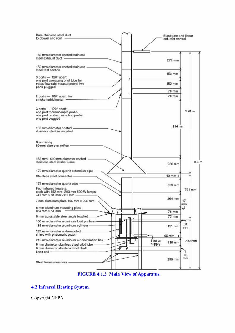
4.1.2 The apparatus shall consist of the following components, shown in Figure 4.1.2: an infrared heating system, a load cell system, an ignition pilot flame and timer, a product gas analysis system, a combustion air distribution system, a watercooled shield, an exhaust system, test section instruments, calibration instruments, and a digital data acquisition system.
Copyright NFPA
FIGURE 4.1.2 Main View of Apparatus.
4.2 Infrared Heating System.
Copyright NFPA
4.2.1* Each of four 241 mm long infrared heaters shall contain six tungstenfilament tubular quartz lamps in a compact reflector body that, for a 120volt input, shall produce 190 kW/m 2 of radiant flux in front of the quartz window that covers the lamps.
4.2.1.1 The emitter of each lamp shall be a 127 mm long tungsten filament in an argon atmosphere enclosed in a 9.5 mm outerdiameter clear quartz tube.
4.2.1.2 The emitter shall operate at a minimum of 2475 K for a 120volt input, to produce a spectral energy peak at 1.15 microns.
4.2.2 Power Controller.
4.2.2.1 The power controller shall maintain the output voltage required by the heater array despite variations in the line voltage and load impedance, through the use of phase angle power control to match the hot/cold resistance characteristics of the tungstenquartz lamps.
4.2.2.2 The controller also shall incorporate average voltage feedback to linearize the relationship between the voltage set by the operator and the output voltage to the lamps.
4.3 Load Cell System.
4.3.1 The load cell system, shown in Figure 4.3.1(a) and Figure 4.3.1(b), shall consist of a load cell, which shall have an accuracy of 0.1 g and a measuring range of 0 g to 1000 g; a 6.35 mm diameter stainless steel shaft at least 330 mm long resting on the load cell support point; a 100 mm diameter, 1.5 mm thick aluminum load platform connected to the upper end of the stainless steel shaft by a collar; and two lowfriction, ballbushing bearings that guide the shaft as it passes through the top and bottom, respectively, of the air distribution chamber.

Copyright NFPA
FIGURE 4.3.1(a) Exploded View of Specimen Mounting.
Copyright NFPA
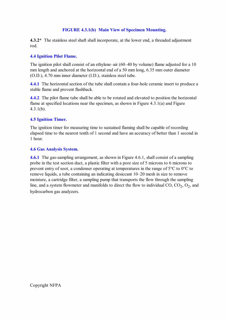
FIGURE 4.3.1(b) Main View of Specimen Mounting.
4.3.2* The stainless steel shaft shall incorporate, at the lower end, a threaded adjustment rod.
4.4 Ignition Pilot Flame.
The ignition pilot shall consist of an ethylene–air (60–40 by volume) flame adjusted for a 10 mm length and anchored at the horizontal end of a 50 mm long, 6.35 mm outer diameter (O.D.), 4.70 mm inner diameter (I.D.), stainless steel tube.
4.4.1 The horizontal section of the tube shall contain a fourhole ceramic insert to produce a stable flame and prevent flashback.
4.4.2 The pilot flame tube shall be able to be rotated and elevated to position the horizontal flame at specified locations near the specimen, as shown in Figure 4.3.1(a) and Figure 4.3.1(b).
4.5 Ignition Timer.
The ignition timer for measuring time to sustained flaming shall be capable of recording elapsed time to the nearest tenth of 1 second and have an accuracy of better than 1 second in 1 hour.
4.6 Gas Analysis System.
4.6.1 The gassampling arrangement, as shown in Figure 4.6.1, shall consist of a sampling probe in the test section duct, a plastic filter with a pore size of 5 microns to 6 microns to prevent entry of soot, a condenser operating at temperatures in the range of 5°C to 0°C to remove liquids, a tube containing an indicating desiccant 10–20 mesh in size to remove moisture, a cartridge filter, a sampling pump that transports the flow through the sampling line, and a system flowmeter and manifolds to direct the flow to individual CO, CO 2 , O 2 , and hydrocarbon gas analyzers.

Copyright NFPA
FIGURE 4.6.1 Flow Diagram of GasSampling System.
4.6.1.1 The sampling probe, made of 6.35 mm (0.25 in.) O.D. stainless steel tubing inserted through a test section port, shall be positioned so that the open end of the tube is at the center of the test section.
4.6.1.2 The sampling probe shall be connected to a tee fitting that allows either sample or calibration gas to flow to the analyzer and the excess to waste.
4.6.2 The carbon dioxide analyzer shall permit measurements from 0 ppm to 15,000 ppm, and the carbon monoxide analyzer shall permit measurements from 0 ppm to 500 ppm concentration levels.
4.6.2.1 Drift shall be not more than ± 1 percent of full scale over a 24hour period.
4.6.2.2 Precision shall be 1 percent of full scale, and the 10 percent to 90 percent of fullscale response time shall be 1 second or less.

Copyright NFPA
4.6.3 The inletair oxygen analyzer shall have a 10 percent to 90 percent of fullscale response time of 1 second or less, an accuracy of 1 percent of full scale, a drift of not more than ± 50 ppm O 2 over onehalf hour, and a range of 0 percent to 50 percent.
4.6.4 An additional oxygen analyzer shall be permitted to measure the depletion of oxygen in the combustion products.
4.6.4.1 This analyzer shall have the same specifications as the inletair analyzer but shall have a concentration range of 19 percent to 21 percent.
4.6.4.2 A hydrocarbon gas analyzer shall be permitted to determine the total gaseous hydrocarbon concentration in the combustion products.
4.6.4.3 This analyzer shall employ the flame ionization method of detection, have a 10 percent to 90 percent of fullscale response time of 1 second or less, and have multiple ranges to permit measurements from a full scale of 10 ppm methane equivalent to 10,000 ppm.
4.7 Combustion Air Distribution System.
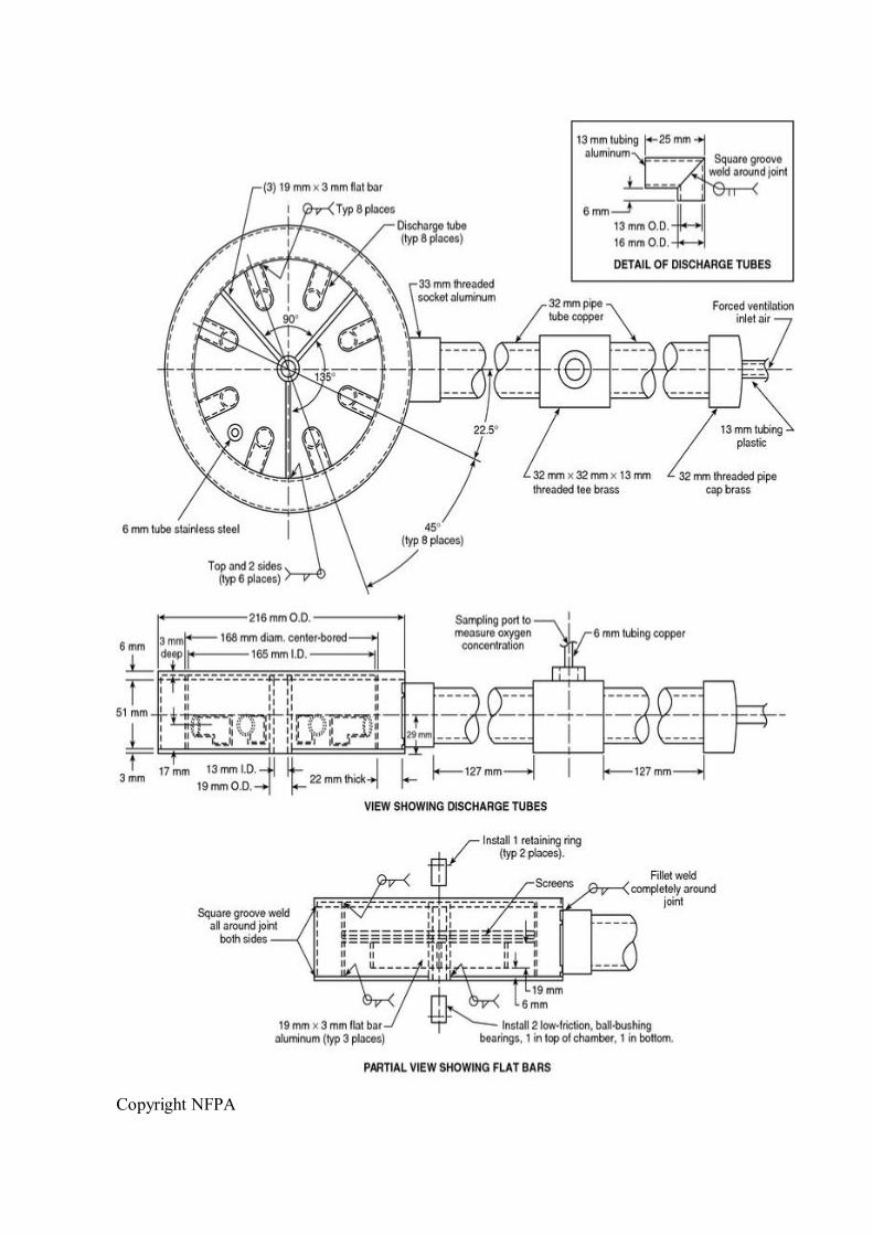
4.7.1* The aluminum air distribution chamber, shown in Figure 4.7.1, shall contain eight discharge tubes arranged in a circle of 165 mm I.D.
Copyright NFPA

Copyright NFPA
FIGURE 4.7.1 Air Distribution Chamber.
4.7.1.1 Each tube shall be aluminum and built to distribute inlet gases to three sets of screens, consisting of stainless steel woven wire cloth of 10, 20, and 30 mesh from bottom to top, respectively, for producing a uniform airflow.
4.7.2 The air supply pipes, shown in Figure 4.7.2, shall consist of an aluminum cylinder extending from the air distribution chamber up to the load platform.
Copyright NFPA
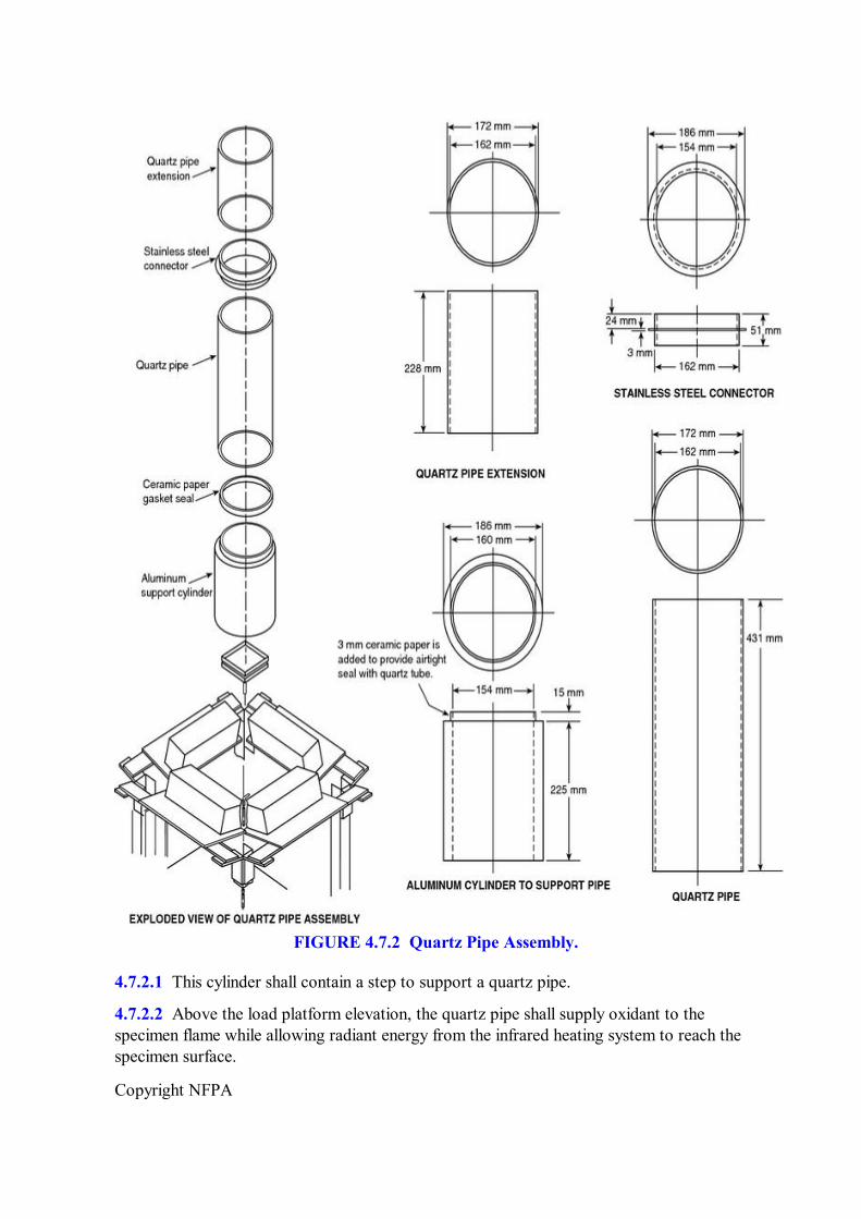
FIGURE 4.7.2 Quartz Pipe Assembly.
4.7.2.1 This cylinder shall contain a step to support a quartz pipe.
4.7.2.2 Above the load platform elevation, the quartz pipe shall supply oxidant to the specimen flame while allowing radiant energy from the infrared heating system to reach the specimen surface.

Copyright NFPA
4.7.2.3 The aluminum support cylinder shall be rigidly attached to the distribution chamber, with the quartz pipe removable.
4.8 WaterCooled Shield.
The watercooled shield, shown in Figure 4.8, shall prevent the specimen from being exposed to the infrared heaters during the 1minute heater stabilization period.
FIGURE 4.8 WaterCooled Shield.
4.8.1 The shield shall consist of two aluminum cylinders welded together with an inlet and outlet for water circulation.
4.8.2 An electrically actuated pneumatic piston shall raise the shield to cover the specimen during test preparation and shall lower the shield within 1 second to expose the specimen at the start of a test.
4.9 Exhaust System.
An exhaust system shall be provided in accordance with 4.9.1 or 4.9.2.
4.9.1 Option 1.
4.9.1.1 The exhaust system shall consist of the following main components: an intake funnel,

Copyright NFPA
as shown in Figure 4.9.1.1(a) and Figure 4.9.1.1(b); a mixing duct, as shown in Figure 4.9.1.1(c) and Figure 4.9.1.1(d); a test section, as shown in Figure 4.9.1.1(e); an exhaust duct, as shown in Figure 4.1.2; and a hightemperature blower to draw gases through the intake funnel, mixing duct, test section, and exhaust duct at flow rates from 0.1 m 3 /sec to 0.3 m 3 /sec.
FIGURE 4.9.1.1(a) Intake Funnel.

Copyright NFPA
FIGURE 4.9.1.1(b) Funnel Flange.

Copyright NFPA
FIGURE 4.9.1.1(c) Mixing Duct.

Copyright NFPA
FIGURE 4.9.1.1(d) Duct Flanges.
Copyright NFPA
Copyright NFPA
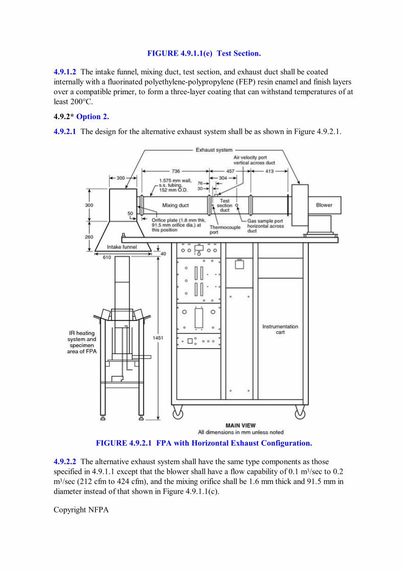
FIGURE 4.9.1.1(e) Test Section.
4.9.1.2 The intake funnel, mixing duct, test section, and exhaust duct shall be coated internally with a fluorinated polyethylenepolypropylene (FEP) resin enamel and finish layers over a compatible primer, to form a threelayer coating that can withstand temperatures of at least 200°C.
4.9.2* Option 2.
4.9.2.1 The design for the alternative exhaust system shall be as shown in Figure 4.9.2.1.
FIGURE 4.9.2.1 FPA with Horizontal Exhaust Configuration.
4.9.2.2 The alternative exhaust system shall have the same type components as those specified in 4.9.1.1 except that the blower shall have a flow capability of 0.1 m 3 /sec to 0.2 m 3 /sec (212 cfm to 424 cfm), and the mixing orifice shall be 1.6 mm thick and 91.5 mm in diameter instead of that shown in Figure 4.9.1.1(c).

Copyright NFPA
4.9.2.3 The alternative exhaust system shall be operated at a flow rate of 0.15 ± 0.015 m 3 /sec (318 ± 32 cfm).
4.10 Test Section Instruments.
4.10.1 Thermocouple Probe.
4.10.1.1 The thermocouple probe shall be inserted through a test section port and positioned so that the exposed, type K measurement bead is at the center of the test section, at the axial position of the gassampling port.
4.10.1.2 The thermocouple probe shall be fabricated of wire no larger than 0.254 mm in diameter for measurement of gas temperature, with a time response in the specified exhaust flow of no more than 1 second and an accuracy of 1°C.
4.10.2* Averaging Pitot Probe and Pressure Transducer. The averaging pitot probe shall be inserted through a test section port 220 mm to 230 mm downstream of the thermocouple port and shall measure the mass flow rate of the gas stream by using at least four sets of flowsensing openings.
4.10.2.1 One set of openings shall face upstream, and the second set shall face downstream and be designed for compatibility with the test section diameter.
4.10.2.2 The differential pressure generated by the probe shall be measured with an electronic pressure transducer (electronic manometer).
4.10.3* SmokeMeasuring Unit.
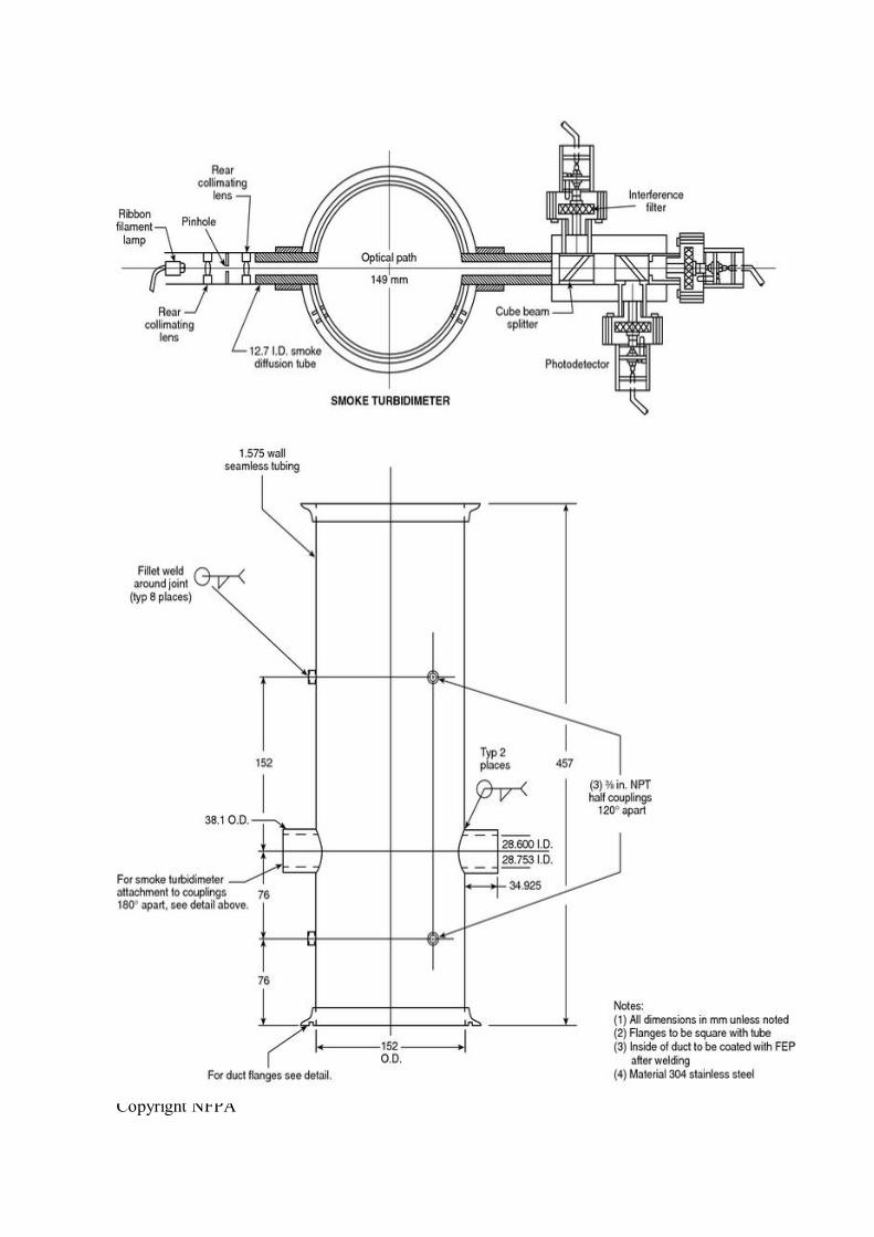
4.10.3.1 A laser smokemeasuring system, as shown in Figure 4.10.3.1, shall be used to measure the smoke extinction coefficient; Figure 4.10.3.1 identifies the laser smokemeasuring system and illustrates a crosssection of the test section duct with an optical path length of 0.152 m.

Copyright NFPA
FIGURE 4.10.3.1 Laser SmokeMeasuring Unit.
4.10.3.2 The smokemeasuring system shall be installed in the test section duct 230 mm downstream of the gassampling port.
4.10.3.3 The smokemeasuring system shall contain the following:
(1) A 0.5 mW nominal power helium–neon laser that emits light energy at the red wavelength of 0.6328 m
(2) Two photodiodes as main and compensating detectors
(3) Associated electronics including amplifier and power supply
4.10.3.4 The laser smokemeasuring system shall be fitted to a rigid cradle that serves as an optical bench.
4.10.3.5 The laser system shall be aligned so that the light falls on the photodetector system, which has two signal outputs typically in the range of 0 volts to 2 volts.
4.11 Heat Flux Gauge.
The infrared heating system shall be calibrated by using a Gardontype total heat flux gauge having a nominal range of 0 kW/m 2 to 100 kW/m 2 and a flat, 6 mm to 8 mm diameter sensing surface coated with a durable, flatblack finish.
4.11.1 The body of the gauge shall be cooled by water above the dew point of the gauge environment.
4.11.2 The gauge shall be rugged and maintain an accuracy of ±3 percent and a repeatability within 0.5 percent between calibrations.
Copyright NFPA
4.11.3 Whenever the infrared heaters are calibrated, the calibration of the heat flux gauge shall be checked through the use of a blackbody ovencalibration facility that compares the gauge response to that of an optical pyrometer with a NISTtraceable calibration, or through the use of a facility that compares the gauge output to that of a reference standard.
4.12 Digital Data Collection.
The digital data collection system shall be capable of recording the output from the CO, CO 2 , hydrocarbon gas, O 2 combustion, and O 2 inlet air analyzers, the load cell, the test section instruments, and the electronic pressure transducer at 1second intervals.
4.12.1 The data for gas concentrations shall be timeshifted to account for delays within the gassampling lines and respective instrument response times.
4.12.2 The data collection system shall have an accuracy corresponding to at least ± 1°C for temperature measurement and ± 0.01 percent of fullscale instrument output for all other channels.
4.12.3 The system shall be capable of recording data for at least 1 hour at 1second intervals.
Chapter 5 Calibration of Equipment
5.1 Radiant Flux Heater.
5.1.1 Infrared heaters shall be calibrated at the start of the test day.
5.1.1.1 The quartz windows, lamps, and back reflective surfaces of the heaters shall be cleaned of any impurity buildup or scratches.
5.1.1.2 The sensing surface of the heat flux gauge shall be positioned to be horizontal, at a location equivalent to the center of the top surface of a horizontal specimen.
5.1.1.3 Calibrations shall be performed, both with and without the quartz pipe in position, by recording infrared heater voltage settings and corresponding heat flux gauge outputs that cover the entire range of flux levels for planned tests.
5.1.2 At least annually, the position of the infrared heaters shall be checked by setting the heater voltage at 90 percent of the maximum value, positioning the heat flux gauge sensing surface to be horizontal, and measuring the heat flux at each of five locations, corresponding to each corner and the center of a square, horizontal specimen, at an elevation equivalent to that of the specimen top surface.
5.1.2.1 The position of each infrared heater shall be adjusted symmetrically, and the heat flux measurements repeated until there is at most a 5 percent mean deviation of the five readings from the average value.
5.1.2.2 Then, the heat flux gauge shall be positioned, with the sensing surface horizontal, to locations equivalent to the vertical axis at the center of a square, horizontal specimen, and the heat flux measured at elevations of 10 mm and 20 mm above and below that equivalent
Copyright NFPA
to the specimen top surface.
5.1.2.3 The heat flux at these four elevations shall be checked to ensure that it is within 5 percent of the value at the elevation of the specimen top surface.
5.2 Gas Analysis Equipment.
5.2.1 The gas analysis equipment shall be calibrated before the first combustion or fire propagation test of the day.
5.2.2 Carbon dioxide and carbon monoxide analyzers shall be calibrated for measurement of the combustion gases by establishing a downscale/zero calibration point and an upscale/span calibration point.
5.2.2.1 The upscale calibration shall be performed with a “span gas” at the upper end of the range that will be used during actual sample analysis and with a “zero gas” for the downscale calibration point at the lower end of the analyzer range.
5.2.2.2 Nitrogen shall be used as the “zero gas” reference source by turning on a cylinder of Grade 5 nitrogen.
5.2.3 The oxygen analyzer for the measurement of inlet oxygen concentration and the optional oxygen analyzer for the measurement of combustion gases shall be calibrated by establishing a downscale/zero calibration point and an upscale/span calibration point.
5.2.3.1 The upscale calibration shall be performed with a “span gas” at the upper end of the range that will be used during actual sample analysis and with a “zero gas” for the downscale calibration point at the lower end of the analyzer range.
5.2.3.2 Grade 5 nitrogen shall be used as the “zero gas” reference source.
5.2.3.3 The optional combustion gas oxygen analyzer shall be checked to ensure that the span (upper range) setting does not change by more than 0.1 percent after the first zero gas (downscale) setting is performed.
5.2.3.4 If the setting does change by more than this amount, then the calibration procedure shall be repeated.
5.2.4 Optional Hydrocarbon Gas Analyzer.
5.2.4.1 The optional hydrocarbon gas analyzer shall be calibrated at the downscale point by using Grade 5 nitrogen as the “zero gas.”
5.2.4.2 Methane at a concentration that matches the operating range of the analyzer shall be used as the “span gas” for the upscale calibration.
5.3 Load Cell.
The load cell shall be calibrated each time it is used.
5.3.1 The output voltage shall be set to zero by adjusting the tare, with the appropriate empty specimen holder in position.
5.3.2 A NISTtraceable weight corresponding to the weight of the specimen to be tested

Copyright NFPA
shall then be placed on the empty holder, and the output voltage shall be measured.
5.3.3 Linearity shall be checked by repeating this procedure with three other NISTtraceable weights so as to cover the entire specimen weight range.
5.4 Heat Release Calibration.
5.4.1 Measurement Process.
5.4.1.1 The heat release rate measurement process shall be calibrated at least monthly to ensure the proper functioning of the fire propagation apparatus.
5.4.1.2* The measured effective heat of combustion of acetone shall be checked to ensure that it is within 5 percent of the reference value of 27,900 kJ/kg and that the measured total delay (or lag) time of the gas analyzers is less than 15 seconds.
5.4.2 The infrared heaters or the pilot shall not be used.
5.4.3 All other required calibration procedures described in Section 5.4 shall be performed.
5.4.4 Inlet airflow shall be checked to ensure that it is set at 200 ± 20 L/min.
5.4.5 The data acquisition program shall be started.
5.4.6 Acetone in the amount of 100 mL shall be placed in a 97 mm diameter heatresistant glass specimen dish on the load cell.
5.4.7 The acetone shall be ignited using a match 30 seconds after the start of data acquisition.
5.4.8 Data acquisition shall be ended 2 minutes after the end of visible flaming.
5.4.9 The effective heat of combustion shall be determined in accordance with the calculation procedure in Section 8.4.
5.4.10 The delay time for the gas analyzers shall be determined by computing the difference between the time when the test section duct gas temperature reaches 50 percent of its steadystate value and the time when the reading of each analyzer reaches 50 percent of its steadystate value.
Chapter 6 Test Specimens
6.1 Specimen Holders.
Four types of specimen holders shall be permitted: horizontal square; horizontal circular, as shown in Figure 6.1(a); vertical, as shown in Figure 6.1(b); and vertical cable, as shown in Figure 6.1(c).
Copyright NFPA
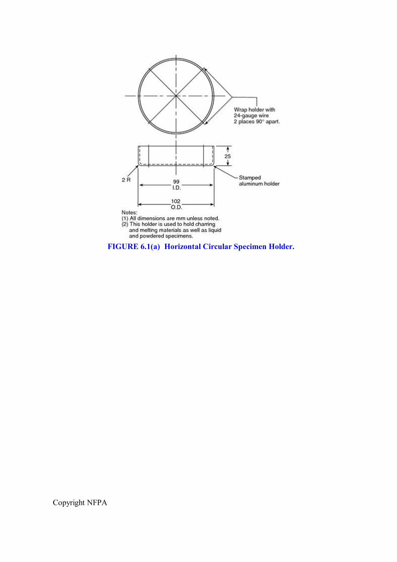
FIGURE 6.1(a) Horizontal Circular Specimen Holder.

Copyright NFPA

Copyright NFPA
FIGURE 6.1(b) Vertical Specimen Holder.
FIGURE 6.1(c) Cable Specimen Holder.
6.1.1 The horizontal square holder shall consist of two layers of “2 mil” (0.05 mm thickness) aluminum foil molded to the sides and bottom of a square specimen.
6.1.2 The horizontal circular holder shall be a 99 mm diameter aluminum dish.

Copyright NFPA
6.1.3 The vertical specimen holder shall be a 485 mm high × 133 mm wide ladder rack.
6.1.4 The vertical cable holder shall be 825 mm high, for supporting a cable specimen 810 mm long and up to 51 mm in diameter.
6.2 Conditioning.
Specimens shall be conditioned, before surface preparation or testing, to moisture equilibrium at a temperature of 23 ± 3°C and a relative humidity of 50 ± 5 percent for 24 hours.
6.3 Specimen Size and Preparation.
6.3.1* Ignition and Combustion Tests of Horizontal Specimens. Specimens for the horizontal square holder shall be cut from planar materials or products to be 101.6 mm × 101.6 mm in area.
6.3.1.1 Square specimens shall have a thickness of no less than 3 mm and no more than 25.4 mm.
6.3.1.2 For materials and products having a thickness greater than 25.4 mm, the unexposed surface shall be cut to reduce the thickness to 25.4 mm.
6.3.1.3 When the ignition test is paired with a fire propagation test, the specimen thickness shall be identical in both tests.
6.3.1.4 Square specimens shall be used with the horizontal square holder.
6.3.1.5 Granular specimens shall be used with the horizontal circular holder by filling the aluminum dish.
6.3.1.6 Cable specimens shall be used with the horizontal circular holder by cutting them to cover the center and at least 20 mm on each side of the center of the aluminum dish.
6.3.1.7 The exposed top surface of square, granular, and cable specimens shall be sprayed with a single coat of flat black paint that is designed to withstand temperatures up to 540 ± 10°C.
6.3.1.8 The paint coating shall be cured by conditioning the specimen at a temperature of 23 ± 3°C and a relative humidity of 50 ± 5 percent for 48 hours.
6.3.1.9 Before testing, the holder containing the specimen shall be placed on a 13 mm thick calcium silicate board having a density of 700 kg/m 3 to 750 kg/m 3 , a thermal conductivity of 0.11 W/mK to 0.13 W/mK, and the same dimensions as the holder, as shown in Figure 6.1(a).
6.3.2 Fire Propagation Test of Vertical Specimens. Vertical specimens shall be cut from planar materials or products to be 101.6 mm in width and 305 mm in height.
6.3.2.1 Vertical specimens shall have a thickness of no less than 3 mm and no more than 13 mm.
6.3.2.2 For materials and products having a thickness greater than 13 mm, the unexposed

Copyright NFPA
surface shall be cut to reduce the thickness to 13 mm.
6.3.2.3 When the fire propagation test is paired with an ignition test, the specimen thickness shall be identical in both tests.
6.3.2.4 Ceramic paper having a density 190 kg/m 3 to 200 kg/m 3 and a thickness of 3.2 mm shall be placed to cover the sides and back surface of the vertical specimen.
6.3.2.5 Two layers of “2 mil” (0.05 mm) thickness aluminum foil shall then be molded to the ceramic paper on the sides and back surface of the vertical specimen, thereby leaving the front surface of the specimen exposed for testing.
6.3.2.6 Following this preparation, the bottom of the vertical specimen shall be placed on the metal baseplate of the vertical holder shown in Figure 6.1(b), with the covered (back) surface of the specimen against the ladder rack.
6.3.2.7 To secure the specimen to the vertical specimen holder, 24 gauge nickel–chromium wire shall be wrapped three turns around the vertical specimen, the ladder rack, and the threaded rods, at distances of 100 mm and 200 mm from the bottom of the specimen.
6.3.2.8 Cable specimens shall be mounted as shown in Figure 6.1(c).
6.4 Mounting Methods.
The exact mounting and retaining methods used shall be specified in the test report if different from the techniques in Section 6.3.
Chapter 7 Test Procedure
7.1 Procedure 1: Ignition Test.
The ignition test shall be performed to determine the TRP, and the CHF of a material, through measurement of the ignition time over a range of external heat fluxes.
7.1.1 Nitrogen for extinguishing flames shall be ready to flow at 100 ± 10 L/min, and cylinders of compressed ethylene and air shall be available to give the specified pilot flame when needed.
7.1.2 The 13 mm thick calcium silicate board supporting the appropriate horizontal specimen holder shall be centered on the aluminum load platform with no quartz pipe in place, to ensure natural airflow.
7.1.3 The exhaust blower shall be turned on.
7.1.4 The pilot flame shall be ignited and adjusted for a 10 mm flame length.
7.1.5 The lighted pilot flame shall be moved to a position 10 mm above the specimen surface and 10 mm radially in from the perimeter of the specimen.
7.1.6 The air and water supplies shall be turned on to cool the infrared heaters.
7.1.7 The watercooled shield surrounding the specimen holder shall be raised to prevent

Copyright NFPA
specimen exposure to external heat flux.
7.1.8 The infrared heater voltage shall be set to produce a 30 kW/m 2 exposure on the specimen surface, and the infrared heater shall be allowed to stabilize for 1 minute.
7.1.9 The watercooled shield shall be lowered to expose the sample to the external heat flux, and the ignition timer shall be started.
7.1.10 The time at the first appearance of vapors from the specimen shall be recorded, and the time to ignition shall be recorded as the time from exposure to the external heat flux until a sustained flame is established for at least a 4second duration.
7.1.11 Nitrogen shall be introduced to extinguish flames.
7.1.12* The specimen shall be removed to a ventilated environment.
7.1.13 The procedures of 7.1.1 through 7.1.12 shall be repeated for infrared heater settings of 35 kW/m 2 , 40 kW/m 2 , 45 kW/m 2 , 50 kW/m 2 , 55 kW/m 2 , and 60 kW/m 2 .
7.1.14 If the specimen ignites at 30 kW/m 2 within 15 minutes, the same procedure shall be repeated at 25 kW/m 2 , 20 kW/m 2 , 15 kW/m 2 , and 10 kW/m 2 , in that order, until there is no ignition for 15 minutes.
7.2 Procedure 2: Combustion Test.
The combustion test shall be conducted to determine the EHC and the y s , and to measure the chemical and convective heat release rates and .
7.2.1 GasSampling System.
7.2.1.1 The gassampling system shall be removing all water vapor and other condensable combustion products.
7.2.1.2 If the sampling system flowmeter indicates a flow of less than 10 L/min, then the sampling system filter elements shall be replaced.
7.2.2 Fresh indicating desiccant and a soot filter shall be installed in the gassampling line.
7.2.3 The flame in the hydrocarbon gas analyzer shall be ignited, and the flameout indicator on the front panel shall be checked to ensure that there is flame ignition.
7.2.4 Nitrogen for extinguishing flames shall be ready to flow at 100 ± 10 L/min, and cylinders of compressed ethylene and air shall be available to produce the specified pilot flame when needed.
7.2.5 Power.
7.2.5.1 The gassampling pump to oxygen, carbon monoxide, carbon dioxide, and hydrocarbon gas analyzers shall be turned on, and correct flow rates shall be set for each instrument.
7.2.5.2 Gas analyzers shall be powered on at all times to maintain constant internal temperatures.

Copyright NFPA
7.2.6 The required calibration procedures shall be performed, as specified in Chapter 5.
7.2.7 The exhaust and air supply blowers servicing the apparatus shall be turned on.
7.2.8 The 13 mm thick calcium silicate board supporting the appropriate horizontal specimen holder shall be centered on the aluminum load platform.
7.2.9 The pilot flame shall be ignited and adjusted for a 10 mm flame length.
7.2.10 The lighted pilot flame shall be moved to a position 10 mm above the specimen surface and 10 mm radially in from the perimeter of the specimen.
7.2.11 The air and water supplies shall be turned on to cool the infrared heaters.
7.2.12 The quartz pipe shall be installed on the mounting step in the aluminum oxidant supply pipe.
7.2.13 The watercooled shield surrounding the specimen holder shall be raised to prevent exposing the specimen to the external heat flux.
7.2.14 The inlet airflow shall be set at 200 ± 20 L/min and the exhaust flow rate set at 0.25 ± 0.025 m 3 /sec.
7.2.15 The infrared heater voltage shall be set to expose the specimen surface to 50 kW/m 2 and shall be allowed to stabilize for 1 minute.
7.2.16 The data acquisition system shall be started.
7.2.17 Thirty to thirtyfive seconds after the start of data acquisition, the watercooled shield shall be lowered to expose the specimen to the infrared heaters.
7.2.18 The following shall be recorded:
(1) Time at the first appearance of vapors from the specimen
(2) Time at ignition
(3) Flame height
(4) Flame color and smokiness
(5) Any unusual flame behavior
(6) Time at flame extinction
7.2.19 If flames reach 35 ± 10 mm above the rim of the collection funnel for more than 30 seconds, they shall be extinguished by introducing nitrogen.
7.2.20 Data acquisition shall be continued for a period of 2 minutes after specimen flaming has ceased.
7.2.21 The specimen shall be removed from the specimen holder and weighed, and the residue mass shall be recorded when the specimen has cooled.
7.2.22 The procedures of 7.2.1 through 7.2.21 shall be repeated to give at least three determinations of the heat release rate, mass loss rate, and smoke yield.
Copyright NFPA
7.3 Procedure 3: Fire Propagation Test.
The fire propagation test shall be performed to determine the FPI of a material, through measurement of the chemical heat release rate of a vertical specimen during and after upward fire propagation.
7.3.1 The procedures of 7.2.1 through 7.2.7 for measurement of heat release rate, with the exception of the load cell calibration, shall be repeated.
7.3.2 The stainless steel load cell shaft and the ballbushing bearings in the air distribution chamber shall be removed and replaced with the appropriate vertical specimen holder, and the specimen shall be installed, so that the bottom edge of the vertical specimen that is to be exposed to external heat flux is at an elevation equivalent to that of the top surface of a horizontal specimen.
7.3.3 The pilot flame shall be ignited and adjusted for a 10 mm flame length.
7.3.4 The exhaust and air supply blowers servicing the apparatus shall be turned on, and a cylinder of Grade 2.6 oxygen shall be connected to the inlet air supply line.
7.3.5 The air and water supplies shall be turned on to cool the infrared heaters.
7.3.6 The quartz pipe shall be installed on the mounting step in the aluminum oxidant supply pipe.
7.3.7 The watercooled shield surrounding the specimen holder shall be raised to prevent exposing the specimen to the external heat flux.
7.3.8 The pilot flame shall be moved to a position 75 mm above the bottom of the specimen and 10 mm away from the specimen surface.
7.3.9 The inlet air/oxygen flow shall be set at 200 ± 20 L/min, the inlet oxygen concentration at 40 percent, and the exhaust flow rate at 0.25 ± 0.025 m 3 /sec.
7.3.10 The infrared heater voltage shall be set to produce 50 kW/m 2 and allowed to stabilize for 1 minute.
7.3.11 The data acquisition program shall be started.
7.3.12 Thirty to thirtyfive seconds after the start of data acquisition, the watercooled shield shall be lowered to expose the lower portion of the vertical specimen to the infrared heaters, and the ignition timer shall be started.
7.3.13 The base area of the specimen shall be preheated for 1 minute.
7.3.13.1 If ignition and fire propagation have not already occurred, the pilot flame shall be moved into contact with the specimen surface 75 mm above the bottom of the specimen to initiate fire propagation.
7.3.13.2 The pilot flame shall then be moved away from the specimen.
7.3.14 The chemical heat release rate shall be measured as a function of time during and after fire propagation, using the combustion test procedures.

Copyright NFPA
7.3.15 The following shall be recorded: the time at the first appearance of vapors from the specimen, the time at ignition, the flame height at 1minute intervals, the flame color and smokiness, any unusual flame behavior, and the time at flame extinction.
7.3.16 The test shall be terminated 2 minutes after the end of visible flaming or if flames reach 35 ± 10 mm above the rim of the collection funnel for more than 30 seconds or if the specimen undergoes noticeable structural deformation.
7.3.17 The procedures of 7.3.1 through 7.3.16 shall be repeated to give at least three heat release rate determinations.
7.4 Safety Precautions.
All normal laboratory safety precautions shall be followed.
7.4.1* During the test, the operator shall use hearing protection and at least shade 5 welding goggles or glasses.
7.4.1.1 The operator shall use protective gloves to insert and remove test specimens.
7.4.1.2 The specimen residue shall be transferred to a fume hood.
7.4.1.3 Neither the infrared heaters nor the associated fixtures shall be touched while they are hot except with protective gloves.
7.4.2 Exhaust System.
7.4.2.1 The exhaust shall be checked for proper operation before testing and shall be discharged away from intakes for the building ventilation system.
7.4.2.2 Provision shall be made for collecting and venting any combustion products that fail, for whatever reason, to be collected by the normal exhaust system of the apparatus.
Chapter 8 Calculations
8.1 Critical Heat Flux (CHF).
The CHF shall be the intercept with the ordinate of a straightline regression fit to data on external heat flux (from the infrared heaters) versus the inverse of time to ignition.
8.1.1 Data shall be from the four lowest values for heat flux (e.g., 30 kW/m 2 , 25 kW/m 2 , 20 kW/m 2 , and 15 kW/m 2 ) in the ignition test.
8.1.2 The standard deviation (or standard error) of the intercept due to data scatter shall be within 10 percent of the regression fit intercept.
8.1.3 Additional data shall be obtained if the standard deviation exceeds this limit.
8.2 Thermal Response Parameter (TRP).
The TRP shall be the slope of a straightline regression fit to data on external heat flux (from the infrared heaters) versus the inverse of the square root of the time to ignition.

Copyright NFPA
8.2.1 Data shall be from the four highest values for external heat flux (e.g., 45 kW/m 2 , 50 kW/m 2 , 55 kW/m 2 , and 60 kW/m 2 ) in the ignition test.
8.2.2 The standard deviation (or standard error) of the slope due to data scatter shall be within 10 percent of the regression fit slope.
8.2.3 Additional data shall be obtained if the standard deviation exceeds this limit.
8.3 Fire Propagation Index (FPI).
8.3.1 The FPI shall be determined from the fire propagation and ignition tests by using the following equation:
where shall be obtained from the fire propagation test and TRP from the ignition test.
8.3.2 The chemical heat release rate shall be determined from the following equation:
8.3.3 The mass flow rates of CO 2 and CO shall be determined from the following equations:
where 353 (kg K/m 3 ) is the product of air density and temperature at normal atmospheric pressure.
8.4 Effective Heat of Combustion (EHC).
The EHC shall be determined from the following equation:
where the summation shall be taken over all combustion test data scans and shall be obtained from 8.3.2 and 8.3.3.
8.5 Smoke Calculations.
8.5.1 The optical density in the test section duct shall be determined from the following equation:

Copyright NFPA
where:
D = optical density (m 1 ) at laser wavelength of 0.6328 m I 0 /I = fraction of light transmitted through smoke L = optical path length (m)
8.5.2 The volume fraction of smoke f v shall be obtained from the following expression (Newman and Steciak, 1987):
where:
= wavelength of the light source ( m) c = coefficient of smoke extinction taken as 7
8.5.3 The mass generation rate (kg/m 2 sec) of smoke shall be given by the following:
where:
= volumetric flow rate in the test section duct (m 3 /sec) A = burning sample surface area (m 2 ) s = value of smoke density taken as 1.1 × 10 3 kg/m 3 with a laser wavelength of
0.6328 mSubstituting these values provides a mass generating rate of smoke, as follows:
8.5.4 The total smoke generated, W s (kg), shall be obtained by the summation of the generation rate from ignition to flameout times as follows:
8.5.4.1 The total mass loss, W m (kg), shall be calculated by the summation of the mass loss rate, from ignition to flameout times, as follows:
Copyright NFPA
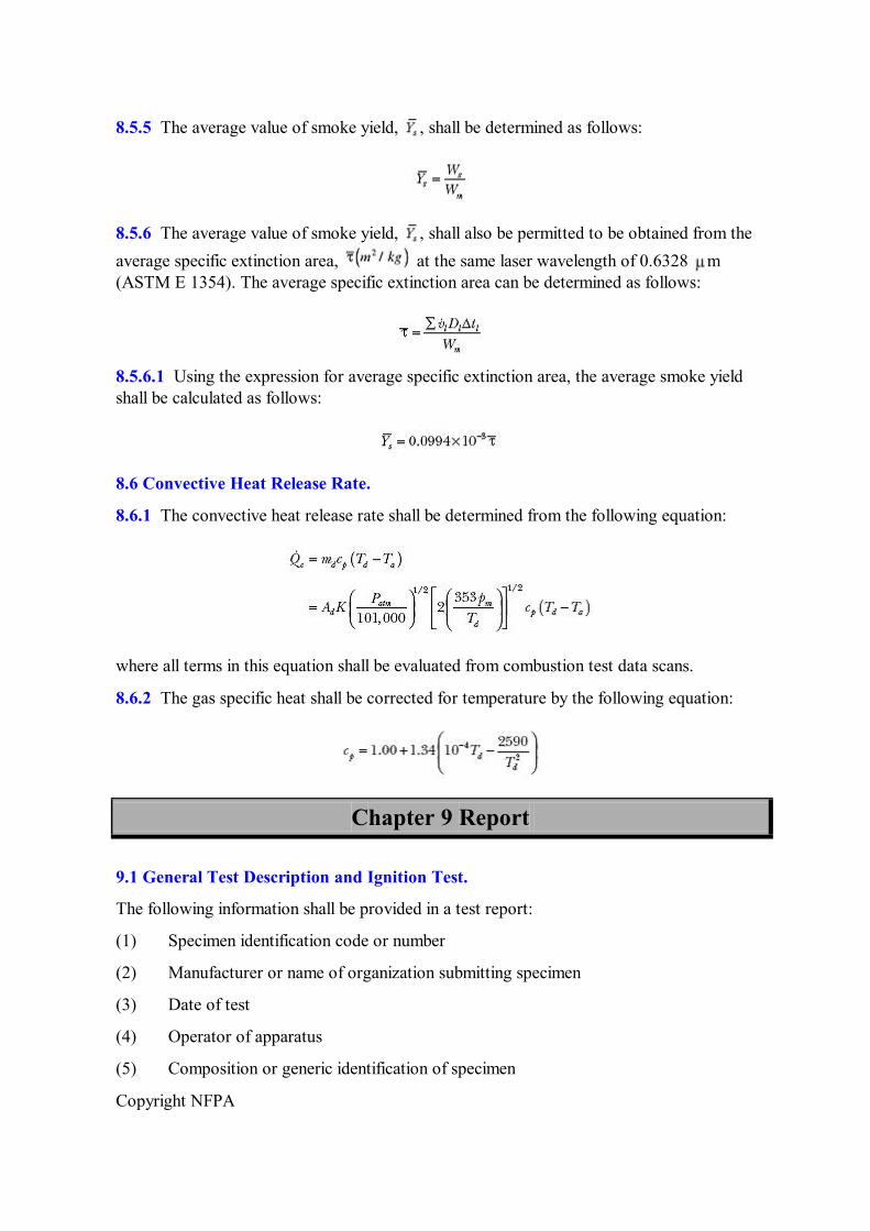
8.5.5 The average value of smoke yield, , shall be determined as follows:
8.5.6 The average value of smoke yield, , shall also be permitted to be obtained from the average specific extinction area, at the same laser wavelength of 0.6328 m (ASTM E 1354). The average specific extinction area can be determined as follows:
8.5.6.1 Using the expression for average specific extinction area, the average smoke yield shall be calculated as follows:
8.6 Convective Heat Release Rate.
8.6.1 The convective heat release rate shall be determined from the following equation:
where all terms in this equation shall be evaluated from combustion test data scans.
8.6.2 The gas specific heat shall be corrected for temperature by the following equation:
Chapter 9 Report
9.1 General Test Description and Ignition Test.
The following information shall be provided in a test report:
(1) Specimen identification code or number
(2) Manufacturer or name of organization submitting specimen
(3) Date of test
(4) Operator of apparatus
(5) Composition or generic identification of specimen

Copyright NFPA
(6) Specimen thickness and dimensions of specimen surface exposed to infrared heaters (mm)
(7) Specimen mass (kg)
(8) Specimen orientation, specimen holder, and description of special mounting procedures
(9) Room temperature (°C) and relative humidity (percent)
(10) Radiant flux from infrared heating system applied to test specimen (kW/m 2 )
(11) Time when vapors are first observed coming from the test specimen (sec)
(12) Time at which there is sustained flaming (sec)
(13) Thermal response parameter (kW sec 1/2 /m 2 )
(14) Critical heat flux (kW/m 2 )
(15) Additional observations (including times of transitory flaming, flashing, or melting)
9.2 Combustion Test.
In addition to the information in Section 9.1(1) through 9.1(15), the report shall include the following information:
(1) Chemical and convective heat release rates per unit exposed area of specimen (kW/m 2 )
(2) Generation rates of carbon monoxide and carbon dioxide (kg/sec)
(3) Effective heat of combustion (kJ/kg)
(4) Smoke yield values corresponding to wavelength of 632.8 nm
(5) Specimen mass remaining after test (kg)
(6) Specimen mass loss rate (kg/sec)
(7) Number of replicate specimens tested under the same conditions
9.3 Fire Propagation Test.
In addition to the information in Sections 9.1 and 9.2, the report shall include the following information:
(1) Chemical heat release rate (kW)
(2) Chemical heat release rate per exposed width or circumference of specimen (kW/m)
(3) Flame height (m)
(4) Thermal response parameter for the specimen, if previously obtained from the ignition test method (kW sec 1/2 /m 2 )
(5) Fire propagation index, calculated using the value in Section 9.3(2) (m 5/3 /kW 2/3 sec 1/2 )

Copyright NFPA
(6) Number of replicate specimens tested under the same conditions
Annex A Explanatory Material
Annex A is not a part of the requirements of this NFPA document but is included for informational purposes only. This annex contains explanatory material, numbered to correspond with the applicable text paragraphs.
A.1.2.1 The test methods described within this document are part of an existing procedure detailed in Approval Standard for Clean Room Materials, Class Number 4910, from FM Global Research.
This standard is different from other fire test standards because it measures the chemical heat release rate during and after the actual process of selfsustained, upward fire propagation on a smallscale, vertical test specimen. Such measurement is made possible by the use of inlet air having a 40 percent oxygen concentration (Tewarson et al. 1981) to differentiate among the flame heat transfer characteristics of burning materials, in the absence of any imposed, highintensity radiant flux. On the other hand, existing standard test methods — for example, ASTM E 906, Standard Test Method for Heat and Visible Smoke Release Rates for Materials and Products, and NFPA 271, Standard Method of Test for Heat and Visible Smoke Release Rates for Materials and Products Using an Oxygen Consumption Calorimeter (equivalent to ASTM E 1354, Standard Test Method for Heat and Visible Smoke Release Rates for Materials and Products Using an Oxygen Consumption Calorimeter) — measure the rate of heat release from burning materials entirely exposed to an external radiant flux.
A.1.2.3 Examples of the use of this methodology for specific polymer materials are described in Annex B. Cleanroom materials and products containing a wide range of polymer composition and internal structure have undergone the ignition, combustion, and/or fire propagation test methods and are also described in Annex B.
A.1.2.4.1 Specimens are coated with black paint for the ignition and combustion test to ensure complete absorption of the radiant heat flux from the infrared heating system (note that the coating does not itself undergo sustained flaming).
A.1.2.4.3 The FPI is based on the theory that fire propagation is related both to the heat flux from the flame of a burning material and to the resistance of a material to ignite (expressed by the TRP) (Tewarson and Khan 1988, Tewarson 2002, and FMGR Class Number 4910, Approval Standard for Clean Room Materials). The flame heat flux is inferred from the chemical heat release rate per unit width of a vertical specimen during upward fire propagation in air having a 40 percent oxygen concentration. The chemical heat release rate is derived from the release rates of carbon dioxide and carbon monoxide (Tewarson 2002).
The 40 percent oxygen concentration is needed to simulate the radiant heat flux from realscale flames, as demonstrated in the discussion on “Flame Heat Flux” and Table 3.4.8 in The SFPE Handbook of Fire Protection Engineering.
A.4.2.1 The following is being provided for informational purposes only and has not been

Copyright NFPA
independently verified, certified, or endorsed by NFPA or any of its technical committees.
A suitable infrared heating system, consisting of four Model 520805 highdensity infrared heaters, Model 500T3/CL/HT lamps, and Model 664 SCR power controller, is available from Research, Inc., 7128 Shady Oak Rd., Minneapolis, MN 55344.
The reflector body of each infrared heater is water cooled, and the lamp chamber, between the front quartz window and reflector, is air cooled, to prolong the life of the heaters. All wavelengths greater than 2 microns emitted by the tungsten filaments in the heater lamps are absorbed by the quartz bulb envelope and heater front window, both of which are air cooled.
A.4.3.2 The incorporation of the threaded adjustment rod at the lower end of the stainless steel shaft is to compensate for horizontal test specimens of different thicknesses.
A.4.7.1 The air distribution chamber is designed so that inlet air flows downward through the eight discharge tubes, disperses on the bottom plate, then rises through the mesh screens toward the aluminum support cylinder.
A.4.9.2 See Annex C for background information on Exhaust System Option 2.
A.4.10.2 The measured differential pressure is proportional to the square of the flow rate. Experience has shown that the averaging pitot probe in this application is reliable (not susceptible to plugging), while minimizing pressure losses in the exhaust system.
A.4.10.3 The power of the laser smokemeasuring unit should be turned on at least one hour before calibration is conducted. Two neutral density glass filters of optical density of 0.3 and 0.8 values accurately calibrated at the laser wavelength of 0.6328 m are required. The smoke system is initially calibrated to read accurately for two different values neutral density filters, and also at 100 percent transmission. Once this calibration is done, only the zero value of extinction coefficient (100 percent transmission) is normally required to be verified prior to each test. See Chapter 8 for smoke calculations.
A.5.4.1.2 The reference value of 27,900 kJ/kg is from “Generation of Heat and Chemical Compounds in Fires,” Section 3, Chapter 4, of The SFPE Handbook of Fire Protection Engineering.
A.6.3.1 The following is being provided for informational purposes only and has not been independently verified, certified, or endorsed by NFPA or any of its technical committees.
A suitable flat, black spray paint is Thurmalox ® Solar Collector Coating, No. 250 Selective Black, available from the Dampney Company, 85 Paris St., Everett, MA 02149.
The paint coating is applied to specimens to ensure surface absorption of the imposed radiant heat flux.
A.7.1.12 Heatresistant gloves should be used when handling hot samples.
A.7.4.1 The test procedures involve high temperatures and combustion reactions. Therefore, hazards can occur such as burns, ignition of extraneous objects or clothing, and inhalation of combustion products.

Copyright NFPA
Annex B Background Material
This annex is not a part of the requirements of this NFPA document but is included for informational purposes only.
B.1 Fire Propagation Apparatus.
The fire propagation apparatus was first developed and used by Factory Mutual Research Corporation (now FM Global Research) in the mid1970s. The apparatus collects the flow of combustion gases from a test specimen and then conditions the flow to uniform velocity, temperature, and species concentration within the test section duct, where the measurements are made. This uniformity is achieved by passing the flow through an orifice at the entry to a mixing duct located six duct diameters upstream of the test section (Ackeret 1967).
B.2 Comparing Fire Propagation Propensity Results with FullScale Fire Behavior.
B.2.1 Fire propagation propensity, characterized by the FPI, has been compared (Tewarson et al. 1998) with fire propagation behavior during fullscale tests involving vertical parallel arrays containing electrical cables insulated with polymeric material (Tewarson et al. 1998 and FMGR Class Number 3972, Cable Fire Propagation Specification Test Standard) or solid panels of polymeric material (Wu 1999 and FMGR Class Number 4910, Approval Standard for Clean Room Materials). The fullscale tests involved fires initiated by a 60 kW propane sandburner located between the 2.44 m high parallel arrays below their base (Ackeret 1967). In addition, fire propagation propensity, characterized by the FPI, has been compared with the fire propagation behavior of conveyor belts in a U.S. Bureau of Mines largescale fire test gallery (Tewarson et al. 1998). A flammable liquid pool fire initiated these conveyor belt fires (Lazzara and Perzak 1989).
B.2.2 Table B.2.2, extracted from Table 1 in “Flammability of Clean Room Materials” (Tewarson et al. 1998), illustrates how the fire propagation index is related to fullscale fire propagation behavior.
Table B.2.2 Comparison of FPI Value with FullScale Fire Propagation Behavior
Material Composition
and Arrangement*
FPI from Fire Propagation Test Method
(m 5/3 /kW 2/3 sec 1/2 )
Fire Propagation Beyond the Ignition Zone at Full Scale †
Gray PVC panel 4 None PVDF panel 5 None White PVC panel 6 None Rigid, Type I PVC panel 8 Limited Modified FRPP panel 9 Yes ETFE panel 9 Limited FRPP panel >10 Yes PMMA panel >10 Yes XLPE/neoprene cable 9 Limited

Copyright NFPA
Table B.2.2 Comparison of FPI Value with FullScale Fire Propagation Behavior
Material Composition
and Arrangement*
FPI from Fire Propagation Test Method
(m 5/3 /kW 2/3 sec 1/2 )
Fire Propagation Beyond the Ignition Zone at Full Scale †
PVC/PVDF cable 7 Limited XLPO cable 9 Limited XLPE/EVA cable 7 Limited PE/PVC cable 20 Yes CR or PVC conveyor belts <6 None CR or SBR conveyor belts 7–8 Limited PVC or SBR conveyor belts >8 Yes
*Polymer abbreviations: (1) PVC — polyvinylchloride (2) PVDF — polyvinylidene fluoride (3) FRPP — fire retarded polypropylene (4) ETFE — ethylenetetrafluoroethylene (5) PMMA — polymethylmethacrylate (6) XLPE — crosslinked polyethylene (7) XLPO — crosslinked polyolefin (8) EVA — ethylvinyl acetate (9) PE — polyethylene (10) CR — chloroprene rubber (11) SBR — styrenebutadiene rubber † Propagation behavior: (1) Yes — fire propagates beyond the ignition zone to the boundary of the exposed material surface (2) Limited — fire propagates beyond the ignition zone, but propagation stops well before the boundary of the exposed material surface (3) None — fire does not propagate beyond the ignition zone, defined as the area of flame coverage by the initiating fire source Source: Tewarson et al. 1998.
Table B.2.2 shows that an FPI equal to or less than a value of 6 m 5/3 /kW 2/3 sec 1/2 correlates very well with fullscale fire behavior in which propagation is limited to the ignition zone.
B.3 Examples of Materials Previously Tested in the FPA.
A wide range of polymeric materials and products has been tested in the fire propagation apparatus, in addition to the polymers noted in Table B.2.2. Tables 34.2, 34.3, and 34.11 in The SFPE Handbook of Fire Protection Engineering illustrate the different polymer groups that have undergone the ignition, combustion, or fire propagation tests.
B.4 Optional Measurement of the Corrosion Potential of Fire Effluent.
B.4.1 Definitions.
B.4.1.1 Average Corrosion Index (ACI). Indicator of corrosion damage caused by the fire effluent from a burning material.

Copyright NFPA
B.4.1.2 C loss . Measured metal loss from the corrosion probe due to a 500minute combined exposure and monitoring time during and after a combustion test, respectively.
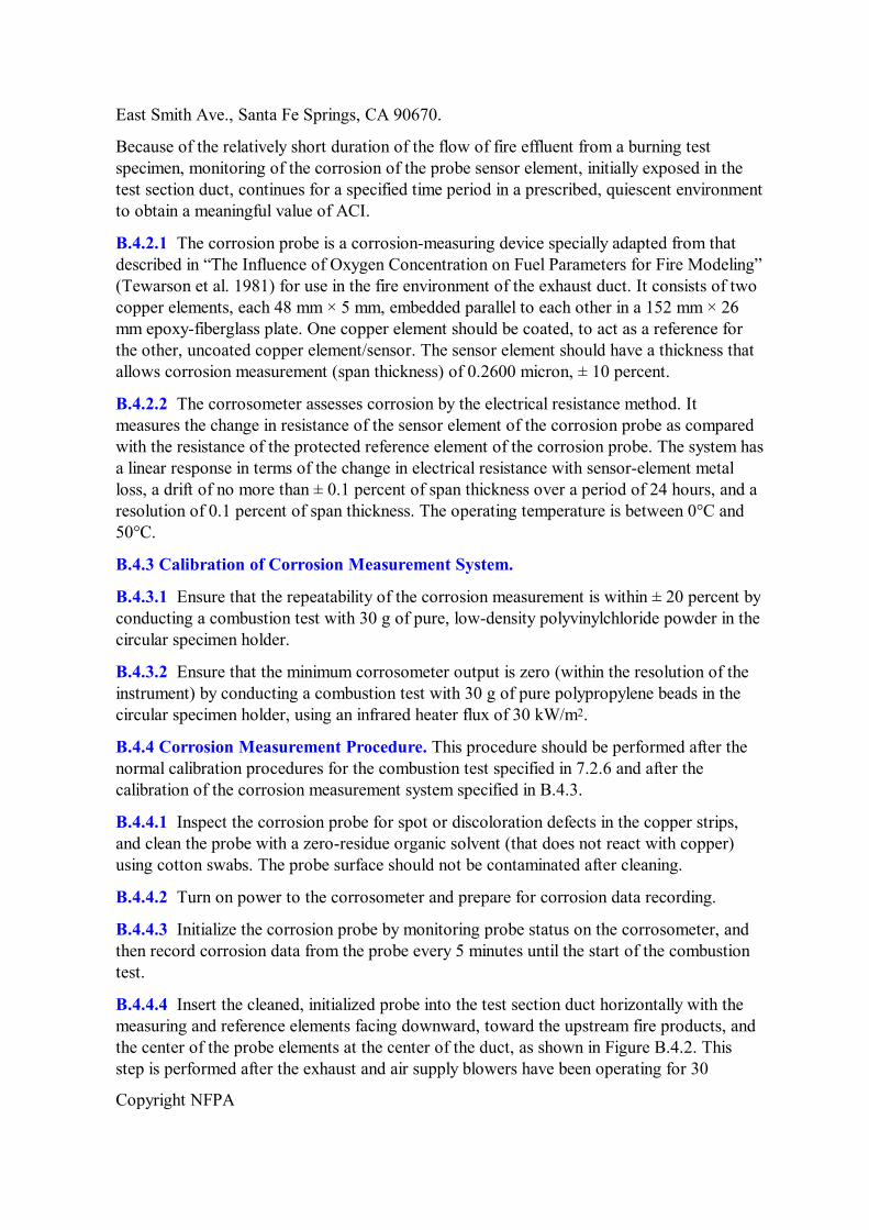
B.4.2 Corrosion Measurement System. The optional corrosion measurement system in the fire propagation apparatus is used to measure metal loss (C loss ) due to corrosion from combustion products, as shown in Figure B.4.2.
FIGURE B.4.2 Corrosion Probe in Exhaust Duct, 300 mm from End of Test Section.
The following is being provided for informational purposes only and has not been independently verified, certified, or endorsed by NFPA or any of its technical committees.
A suitable corrosion measurement system is the Model P/N 657501X1 corrosion probe with the Model RCS8 Corrosometer, available from Rohrback Cosasco Systems, Inc., 11841
Copyright NFPA
East Smith Ave., Santa Fe Springs, CA 90670.
Because of the relatively short duration of the flow of fire effluent from a burning test specimen, monitoring of the corrosion of the probe sensor element, initially exposed in the test section duct, continues for a specified time period in a prescribed, quiescent environment to obtain a meaningful value of ACI.
B.4.2.1 The corrosion probe is a corrosionmeasuring device specially adapted from that described in “The Influence of Oxygen Concentration on Fuel Parameters for Fire Modeling” (Tewarson et al. 1981) for use in the fire environment of the exhaust duct. It consists of two copper elements, each 48 mm × 5 mm, embedded parallel to each other in a 152 mm × 26 mm epoxyfiberglass plate. One copper element should be coated, to act as a reference for the other, uncoated copper element/sensor. The sensor element should have a thickness that allows corrosion measurement (span thickness) of 0.2600 micron, ± 10 percent.
B.4.2.2 The corrosometer assesses corrosion by the electrical resistance method. It measures the change in resistance of the sensor element of the corrosion probe as compared with the resistance of the protected reference element of the corrosion probe. The system has a linear response in terms of the change in electrical resistance with sensorelement metal loss, a drift of no more than ± 0.1 percent of span thickness over a period of 24 hours, and a resolution of 0.1 percent of span thickness. The operating temperature is between 0°C and 50°C.
B.4.3 Calibration of Corrosion Measurement System.
B.4.3.1 Ensure that the repeatability of the corrosion measurement is within ± 20 percent by conducting a combustion test with 30 g of pure, lowdensity polyvinylchloride powder in the circular specimen holder.
B.4.3.2 Ensure that the minimum corrosometer output is zero (within the resolution of the instrument) by conducting a combustion test with 30 g of pure polypropylene beads in the circular specimen holder, using an infrared heater flux of 30 kW/m 2 .
B.4.4 Corrosion Measurement Procedure. This procedure should be performed after the normal calibration procedures for the combustion test specified in 7.2.6 and after the calibration of the corrosion measurement system specified in B.4.3.
B.4.4.1 Inspect the corrosion probe for spot or discoloration defects in the copper strips, and clean the probe with a zeroresidue organic solvent (that does not react with copper) using cotton swabs. The probe surface should not be contaminated after cleaning.
B.4.4.2 Turn on power to the corrosometer and prepare for corrosion data recording.
B.4.4.3 Initialize the corrosion probe by monitoring probe status on the corrosometer, and then record corrosion data from the probe every 5 minutes until the start of the combustion test.
B.4.4.4 Insert the cleaned, initialized probe into the test section duct horizontally with the measuring and reference elements facing downward, toward the upstream fire products, and the center of the probe elements at the center of the duct, as shown in Figure B.4.2. This step is performed after the exhaust and air supply blowers have been operating for 30
Copyright NFPA
minutes (see 7.2.7).
B.4.4.5 Monitor corrosion data every minute during the combustion test.
B.4.4.6 Remove the corrosion probe from the test section duct 30 minutes after the end of the combustion test, and place the probe inside an environmentally controlled chamber maintained at an ambient temperature of 23 ± 3°C and a relative humidity of 60 ± 5 percent. Monitor corrosion data from the probe in the chamber every 5 minutes for at least 16 hours.
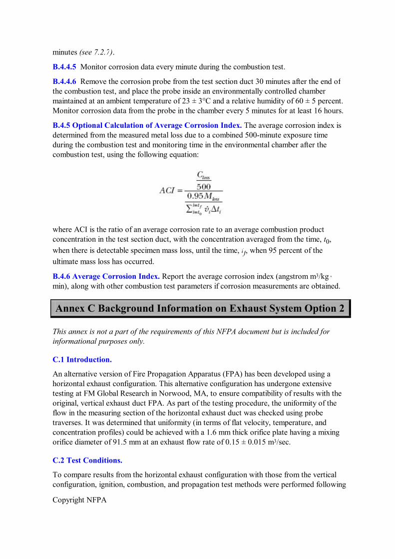
B.4.5 Optional Calculation of Average Corrosion Index. The average corrosion index is determined from the measured metal loss due to a combined 500minute exposure time during the combustion test and monitoring time in the environmental chamber after the combustion test, using the following equation:
where ACI is the ratio of an average corrosion rate to an average combustion product concentration in the test section duct, with the concentration averaged from the time, t 0 , when there is detectable specimen mass loss, until the time, t f , when 95 percent of the ultimate mass loss has occurred.
B.4.6 Average Corrosion Index. Report the average corrosion index (angstrom m 3 /kg min), along with other combustion test parameters if corrosion measurements are obtained.
Annex C Background Information on Exhaust System Option 2
This annex is not a part of the requirements of this NFPA document but is included for informational purposes only.
C.1 Introduction.
An alternative version of Fire Propagation Apparatus (FPA) has been developed using a horizontal exhaust configuration. This alternative configuration has undergone extensive testing at FM Global Research in Norwood, MA, to ensure compatibility of results with the original, vertical exhaust duct FPA. As part of the testing procedure, the uniformity of the flow in the measuring section of the horizontal exhaust duct was checked using probe traverses. It was determined that uniformity (in terms of flat velocity, temperature, and concentration profiles) could be achieved with a 1.6 mm thick orifice plate having a mixing orifice diameter of 91.5 mm at an exhaust flow rate of 0.15 ± 0.015 m 3 /sec.
C.2 Test Conditions.
To compare results from the horizontal exhaust configuration with those from the vertical configuration, ignition, combustion, and propagation test methods were performed following

Copyright NFPA
Sections 7.1, 7.2, and 7.3, respectively, with acetone liquid, 9.5 mm thick clear PMMA, 9.5 mm thick rigid PVC, 12.7 mm thick rigid CPVC, or combination thereof. Acetone was tested without any external heat flux, respectively, in normal air. The CPVC specimens were tested in a gaseous mixture having a 40 percent oxygen concentration, by volume, generated by adding oxygen to ambient air.
C.3 Test Results for Effective Heat of Combustion.
Table C.3 summarizes test results calculated following Section 8.4.
Table C.3 Effective Heat of Combustion
Specimen Composition
Effective Heat of Combustion — Vertical Exhaust Configuration
(kJ/g)
Effective Heat of Combustion — Horizontal Exhaust Configuration
(kJ/g) Acetone 27.1 26.1 PMMA 23.2 24.4 Rigid PVC 6.86 6.4
C.4 Test Results for Time Ignition.
Table C.4(a) and Table C.4(b) present the measured time to ignition as a function of incident heat flux for PMMA and rigid PVC specimens respectively.
Table C.4(a) Ignition Test Results for PMMA
Incident Heat Flux (kW/m 2 )
Ignition Time — Vertical Exhaust Configuration
(sec)
Ignition Time — Horizontal Exhaust Configuration
(sec) 30 347.4 38.7 40 22.4 24 50 14.4 15.4 60 10.1 10.9
Table C.4(b) Ignition Test Results for Rigid PVC
Incident Heat Flux (kW/m 2 )
Ignition Time — Vertical Exhaust Configuration
(sec)
Ignition Time — Horizontal Exhaust Configuration
(sec) 30 117 114 40 72.1 75.8 50 47.3 49.2 60 34.6 34.9
Note: Samples were restrained with 24gauge nickel–chromium wire.

Copyright NFPA
C.5 Test Results for Heat Release Rate in the Combustion Test Method.
The chemical heat release rates for horizontal PMMA and rigid PVC are shown in Figure C.5 as a function of time. The chemical heat release rate profiles are very similar for the two exhaust duct orientations.
FIGURE C.5 Heat Release Rate Time History for PMMA and Rigid PVC.
C.6 Test Results for Heat Release Rate in the Propagation Test Method.
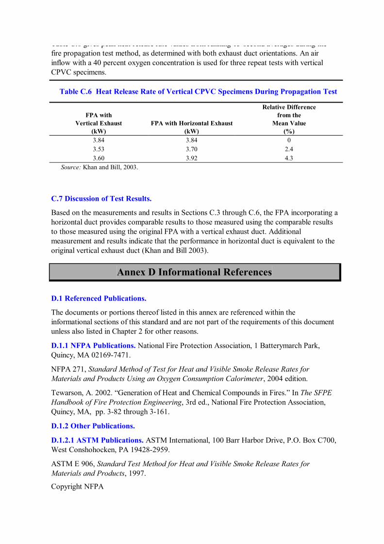
Table C.6 gives peak heat release rate values from running 15second averages during the fire propagation test method, as determined with both exhaust duct orientations. An air inflow with a 40 percent oxygen concentration is used for three repeat tests with vertical CPVC specimens.
Table C.6 Heat Release Rate of Vertical CPVC Specimens During Propagation Test
Copyright NFPA
Table C.6 gives peak heat release rate values from running 15second averages during the fire propagation test method, as determined with both exhaust duct orientations. An air inflow with a 40 percent oxygen concentration is used for three repeat tests with vertical CPVC specimens.
Table C.6 Heat Release Rate of Vertical CPVC Specimens During Propagation Test
FPA with Vertical Exhaust
(kW) FPA with Horizontal Exhaust
(kW)
Relative Difference from the
Mean Value (%)
3.84 3.84 0 3.53 3.70 2.4 3.60 3.92 4.3
Source: Khan and Bill, 2003.
C.7 Discussion of Test Results.
Based on the measurements and results in Sections C.3 through C.6, the FPA incorporating a horizontal duct provides comparable results to those measured using the comparable results to those measured using the original FPA with a vertical exhaust duct. Additional measurement and results indicate that the performance in horizontal duct is equivalent to the original vertical exhaust duct (Khan and Bill 2003).
Annex D Informational References
D.1 Referenced Publications.
The documents or portions thereof listed in this annex are referenced within the informational sections of this standard and are not part of the requirements of this document unless also listed in Chapter 2 for other reasons.
D.1.1 NFPA Publications. National Fire Protection Association, 1 Batterymarch Park, Quincy, MA 021697471.
NFPA 271, Standard Method of Test for Heat and Visible Smoke Release Rates for Materials and Products Using an Oxygen Consumption Calorimeter, 2004 edition.
Tewarson, A. 2002. “Generation of Heat and Chemical Compounds in Fires.” In The SFPE Handbook of Fire Protection Engineering, 3rd ed., National Fire Protection Association, Quincy, MA, pp. 382 through 3161.
D.1.2 Other Publications.
D.1.2.1 ASTM Publications. ASTM International, 100 Barr Harbor Drive, P.O. Box C700, West Conshohocken, PA 194282959.
ASTM E 906, Standard Test Method for Heat and Visible Smoke Release Rates for Materials and Products, 1997.

Copyright NFPA
ASTM E 1354, Standard Test Method for Heat and Visible Smoke Release Rates for Materials and Products Using an Oxygen Consumption Calorimeter, 2004.
D.1.2.2 FMGR Publications. FM Global Research, FM Global, 1301 Atwood Avenue, P.O. Box 7500, Johnston, RI 02919.
Class Number 3972, Cable Fire Propagation Specification Test Standard, March 1994.
Class Number 4910, Approval Standard for Clean Room Materials, September 1997.
Tewarson, A., R. G. Bill, Jr., A. Braga, V. DeGiorgio, and G. Smith. 1998. “Flammability of Clean Room Materials.” InWhite Paper, FMRC J.I. 0B0J8.RC.
D.1.2.3 Other Publications.
Ackeret, J. 1967. “Aspects of Internal Flow.” In Fluid Mechanics of Internal Flow (G. Sovran, ed.), Elsevier, New York, p. 1.
Khan, M. M. and R. G. Bill Jr. 2003. “Comparison of Flammability Measurements in Vertical and Horizontal Exhaust Duct in the ASTM E 2058 Fire Propagation Apparatus.” Fire Mater. 27: 253–266.
Lazzara, C. P. and F. J., Perzak. 1989. “Conveyor Belt Flammability Test: Comparison of LargeScale Gallery and LaboratoryScale Tunnel Results.” In Proceedings of 23rd International Conference of Safety in Mines, Mines Research Institute, Washington, DC, Sept. 11–15, pp. 138–150.
Tewarson, A. and M. M. Khan. 1988. “Flame Propagation for Polymers in Cylindrical Configuration and Vertical Orientation.” In TwentySecond Symposium (International) on Combustion. The Combustion Institute, Pittsburgh, PA, pp. 1231–1240.
Tewarson, A., J. L. Lee, and R. F. Pion. 1981. “The Influence of Oxygen Concentration on Fuel Parameters for Fire Modeling.” In Eighteenth Symposium (International) on Combustion. The Combustion Institute, Pittsburgh, PA, pp. 563–570.
Wu, P. K. 1999. “Parallel Panel Fire Tests for Flammability Assessment.” In Proceedings of the 8th International Fire Science and Engineering Conference (Interflam '99). Interscience Communications, London, pp. 605–614.
D.2 Informational References. (Reserved)
D.3 References for Extracts in Informational Sections. (Reserved)