nhrc automatic transfer switch replacement
TRANSCRIPT
NHRC AUTOMATIC TRANSFER
SWITCH REPLACEMENT AT NATIONAL HYDROLOGY RESEARCH
CENTRE
SPECIFICATIONS REAL PROPERTY MANAGEMENT DIVISION, TECHNICAL SERVICES 11 INNOVATION BLVD. SASKATOON, SK S7N 3H5 PROJECT: NHRC-005-JI301 PO: K4A22-14-0854 DATE: FEBRUARY 28, 2015 ISSUED FOR TENDER
Project No: NHRC-005-Ji301 00 00 02 Saskatoon, SK – National Hydrology Research Centre TABLE OF CONTENTS AUTOMATIC TRANSFER SWITCH REPLACEMENT Page 1
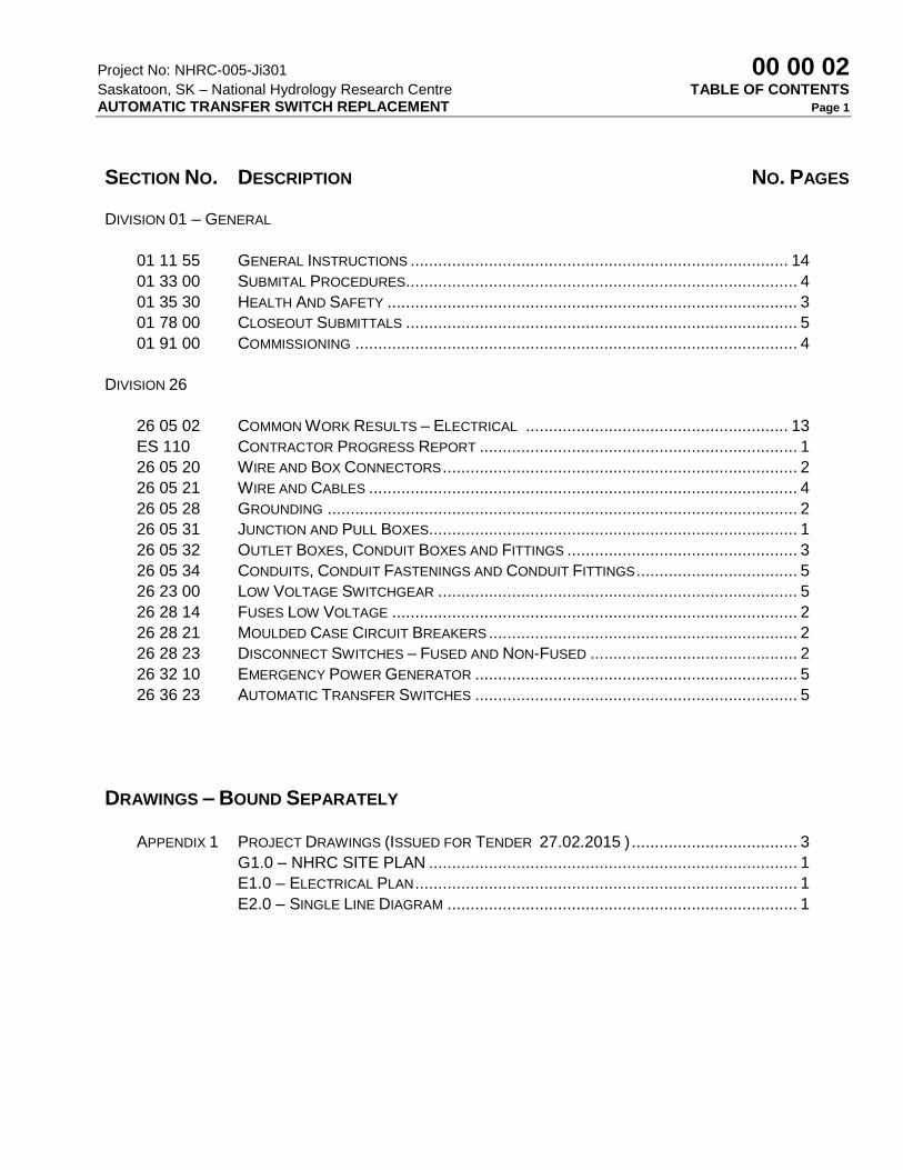
SECTION NO. DESCRIPTION NO. PAGES
DIVISION 01 – GENERAL
01 11 55 GENERAL INSTRUCTIONS .................................................................................. 14
01 33 00 SUBMITAL PROCEDURES..................................................................................... 4
01 35 30 HEALTH AND SAFETY ......................................................................................... 3
01 78 00 CLOSEOUT SUBMITTALS ..................................................................................... 5
01 91 00 COMMISSIONING ................................................................................................ 4
DIVISION 26
26 05 02 COMMON WORK RESULTS – ELECTRICAL ......................................................... 13
ES 110 CONTRACTOR PROGRESS REPORT ..................................................................... 1
26 05 20 WIRE AND BOX CONNECTORS ............................................................................. 2
26 05 21 WIRE AND CABLES ............................................................................................. 4
26 05 28 GROUNDING ...................................................................................................... 2
26 05 31 JUNCTION AND PULL BOXES................................................................................ 1
26 05 32 OUTLET BOXES, CONDUIT BOXES AND FITTINGS .................................................. 3
26 05 34 CONDUITS, CONDUIT FASTENINGS AND CONDUIT FITTINGS ................................... 5
26 23 00 LOW VOLTAGE SWITCHGEAR .............................................................................. 5
26 28 14 FUSES LOW VOLTAGE ........................................................................................ 2
26 28 21 MOULDED CASE CIRCUIT BREAKERS ................................................................... 2
26 28 23 DISCONNECT SWITCHES – FUSED AND NON-FUSED ............................................. 2
26 32 10 EMERGENCY POWER GENERATOR ...................................................................... 5
26 36 23 AUTOMATIC TRANSFER SWITCHES ...................................................................... 5
DRAWINGS – BOUND SEPARATELY
APPENDIX 1 PROJECT DRAWINGS (ISSUED FOR TENDER 27.02.2015 ) .................................... 3
G1.0 – NHRC SITE PLAN ................................................................................ 1
E1.0 – ELECTRICAL PLAN ................................................................................... 1
E2.0 – SINGLE LINE DIAGRAM ............................................................................ 1

Project No: NHRC-005-Ji301 01 11 55 Saskatoon, SK – National Hydrology Research Centre GENERAL INSTRUCTIONS AUTOMATIC TRANSFER SWITCH REPLACEMENT Page 1
1. SUMMARY OF WORK 1. The Contractor shall provide all labour and materials required to complete the replacement
of the Emergency Transfer Switch associated with MCC 1A and generator control panel at the National Hydrology Research Centre, 11 Innovation Blvd. Saskatoon, SK as described in the attached plans and specifications.
2. The work on this contract includes coordination and cooperation with other contractors and
building personnel working on the site. 3. Work to be performed under this Contract includes, but is not limited to, the following items
covered further in the Contract Documents, items below summarize major equipment, refer to full Contract Documents for complete listing.
.1 Remove the existing equipment which includes: 1. 1x Generator Control Panel 2. 1x Emergency Transfer switch
.2 Supply, install and connect new equipment 1. 1x Emergency Closed Transition Transfer Switch c/w Manual Bypass 2. 1x Engine Mounted control Panel 3. 1x Emergency CDP 4. 1x Switch/fuse in existing transfer switch enclosure
.3 Review the single line diagram provided. Contractor shall review the electrical distrubtion on site and update the single line diagram to provide all breaker sizes and trip settings for the main distriburion, CDPs and MCC on site. Breaker sizes for branch panels are not required.
4. The scope of the electrical work is as follows:
.1 Run new feeders as required for the project. This will prepare the installation for
the new layout. These feeders include:
1. Feeders from new switch/fuse in mcc-1 to new transfer switch location
2. Feeders from new transfer switch to mcc-1a
3. Feeders from the emergency generator to the new e-cdp
4. Feeders from the e-cdp to the new transfer switch location.
2. Set into place the new closed transition transfer switch as shown on the plans.
3. Terminate the following feeds onto the new transfer switch
1. Utility power from mcc 1.
2. Emergency power from e-cdp
3. Load feeder to mcc1a, emergency and load feeders into the new transfer
switch.
4. Set into place the feeders for a temporary generator to mcc1a.
5. Request a shutdown of the emergency power to mcc1a and complete the change

Project No: NHRC-005-Ji301 01 11 55 Saskatoon, SK – National Hydrology Research Centre GENERAL INSTRUCTIONS AUTOMATIC TRANSFER SWITCH REPLACEMENT Page 2
over at a time acceptable to the owner.
6. Remove existing generator control panel from wall. Install new control panel on
generator and install new e-cdp in location shown on plans.
7. Terminate the following feeders
1. Feeder from the generator to e-cdp
2. Feeder from e-cdp to the new transfer switch.
3. Feeder from e-cdp to existing transfer switch for mcc2
4. Feeder from e-cdp to existing chiller transfer switch. Reroute existing
feeder as required to terminate on new e-cdp.
5. Feeder associated with the existing load bank.
8. Request a shutdown of mcc-1
1. Remove the existing transfer switch from mcc1.
2. Install new switch/fuse into existing transfer switch location. Make
modifications to mcc-1 as required to suite new switch fuse layout.
3. Terminate all feeders associated with the new switch/fuse
9. Test/commission the emergency generator to ensure that the new generator
control panel functions properly, via loading from a rented 400kw load bank.
10. Test/commission the new emergency transfer switch to ensure that it functions
properly. Testing shall include the following and shall be conducted in the
presence of the consultant:
1. Testing the transfer switch while the generator is' on' to ensure that the
transfer switch carries the load seamlessly under test conditions between
utility power and emergency and back to utility power again.
2. Testing the transfer switch while the generator is off by opening up the
switch/fuse located in mcc-1 to ensure that the generator starts and the
transfer switch switches the load to emergency power. The switch in mcc-1
shall then be switch back 'on' to ensure that the generator switches back to
utility power seamlessly.
3. The transfer switch shall be tested in manual bypass mode.
11. Confirm that a shutdown of MCC-1A is required.
12. Remove the conductors from the temporary generator to mcc-1a and tie in the
permanent feeders from e-cdp
13. Test the transfer switch function again under the load conditions of mcc-1a
Project No: NHRC-005-Ji301 01 11 55 Saskatoon, SK – National Hydrology Research Centre GENERAL INSTRUCTIONS AUTOMATIC TRANSFER SWITCH REPLACEMENT Page 3
2. TIME OF COMPLETION 1. Commence work in accordance with notification of acceptance of your tender submission
and complete the work including rectification of deficiencies within twelve (12) weeks of commencement.
3. HOURS OF WORK 1. Work shall be carried out Monday to Friday from 08:00hrs to 16:15hrs. 2. Shutdown, bypassing or isolating any parts effecting the electrical shall be undertaken
after hours, Monday through Friday from 17:30hrs to 06:00hrs and/or on weekends from 06:00hrs to 18:00hrs.
3. Lock-Out / Tag-Out (LOTO) work shall be completed off-hours Monday through Friday
from 17:30hrs to 07:00hrs and and/or on weekends from 06:00hrs to 18:00hrs. All Internal & External LOTO permits will be required to commence work.
4. Live Work procedures will not be permitted on this site. 5. The Contractor shall not permit his personnel to work alone on this project when the
following activities are undertaken: 1. Work assessment determined that the potential health & safety risk is high; 2. Work requiring entry into or work within a Confined Space; 3. Work requiring Lock-Out / Tag-Out (LOTO); 4. Work requiring use of fall arrest equipment; 5. Work on scaffolding; 6. Work requiring supplied air respirators or similar equipment; 7. Hot Work and/or Hot Tap activities; 8. Work involving cranes or hoisting; 9. Work or work situations identified by the Engineer.
6. Work affecting laboratory operations shall be carried out after normal hours as defined in
3.1 above. Any shut down of service effecting laboratory operations requires a minimum of 48 hours notice.
4. SCHEDULING 1. On award of contract submit a bar chart construction schedule for the work, indicating
anticipated progress stages within time of completion. Minimum stages include, mobilization, shop drawing, product data MSDS sheets and samples submittal, order and delivery of major components and equipment, major approvals stages, interim and final inspection times, commissioning timeframes, final deficiency corrections, training, demobilization and manuals submission. When schedule has been reviewed and approved by the Engineer take necessary measures to complete work within scheduled times. Do not change schedule without written approvals from the Engineer.
5. CONTRACT DOCUMENTS

Project No: NHRC-005-Ji301 01 11 55 Saskatoon, SK – National Hydrology Research Centre GENERAL INSTRUCTIONS AUTOMATIC TRANSFER SWITCH REPLACEMENT Page 4
1. Drawings and specifications are complementary, items shown or mentioned in one and
not in the other are deemed to be included in the contract work. 2. Any questions that arise in relation to the design shall be brought to the attention of the
Engineer. Failure to comply with this procedure may necessitate amendments and other layout modifications as required to complete the Work, costs of which shall be solely the responsibility of the Contractor.
3. Study all documents, which describe, or are related to any operation before
commencement of that operation. Report discrepancies discovered between existing conditions and documentation. Obtain ruling on required interpretation before commencing work.
4. Any changes to the scope of work are to be confirmed in writing by the Engineer and
Contract value changes approved, prior to start of said work.
5. The cost of any additional work to the Owner shall be the actual cost of the work plus ten
percent (10%) overhead and ten percent (10%) profit on the actual cost of the work. 6. CONTRACTOR’S USE OF SITE 1. Do not unreasonably encumber site, with material or equipment. 2. Execute the work with the least possible interference or disturbance to the normal use of
the exiting premises. Make arrangements with the Engineer to facilitate the work as stated.
3. Maintain existing services to the building and provide for personnel and vehicle access. 4. Maintain a proper solid or chain link security fence c/w suitable locks around work and
storage areas at all times. 5. Where security is reduced by the work, provide temporary means to maintain security. 6. Contractor to supply their own site trailer (if required) phone, fax, and storage box. No
storage will be provided within the building. Accommodation will be made for limited on-site storage at the discretion of the Engineer in area designated by the Engineer.
7. Maintain 1 copy of each of the following at the job site:
.1 Contract drawings
.2 Contract specifications
.3 Addenda to contract documents
.4 Copy of approved work schedule
.5 Reviewed/approved shop drawings
.6 Change orders
.7 Other modifications to contract
.8 Field test reports
.9 Reviewed/approved samples
.10 Manufacturers’ installation and application instructions

Project No: NHRC-005-Ji301 01 11 55 Saskatoon, SK – National Hydrology Research Centre GENERAL INSTRUCTIONS AUTOMATIC TRANSFER SWITCH REPLACEMENT Page 5
.11 One set of record drawings and specifications for “as-built” purposes .12 National Building Code of Canada 2010 .13 Current construction standards of workmanship listed in technical Sections .14 Project Safety Plan – Including emergency contact names and directions to the
nearest hospital. 7. CONTRACTOR PROJECT SUPERINTENDENT 1. The Contractor shall, upon award of contract, designate a Project Superintendent. The
Contractor shall provide the name, cellular phone number to the Engineer at the preconstruction meeting. The Project Superintendent shall have full responsibility for the project and shall be authorized to accept and act upon any notice or direction provided by the Engineer. Project Superintendent shall be available on site at all times that work is being performed under this contract.
2. Supervise and direct all persons engaged in the work, including all tradesmen and
suppliers. Become familiar with the requirements of each trade. Coordinate delivery and work operations. Examine the work of all trades during work operations to ensure compliance with the contract requirements. Expedite all work to maintain the contract schedule.
3. Cooperate with all other contractors working on site in parallel or related projects. 4. Attend coordination and project meetings at the direction of the Engineer. 8. CONTRACTOR and SUB CONTRACTORS 1. The Contractor agrees to employ those sub-contractors proposed by him in writing as
listed in the Contractor’s tender submission. 2. Do not change or substitute approved contractor for sub-contractors without prior
authorization from the design authority. 3. Contractor and sub-contractor personnel shall be qualified as per definitions under the
Trades Qualification and Apprenticeship Acts and as required by regulatory agencies in Saskatchewan.
4. Electrical work shall be carried out by qualified and licensed electrical contractors as per
Saskatchewan regulations. 9. WORKMANSHIP 1. Workmanship shall be the best quality, executed by workers experienced and skilled in the
respective duties for which they are employed. Immediately notify the Engineer, if required, if work is such as to make it impractical to produce required results.
Project No: NHRC-005-Ji301 01 11 55 Saskatoon, SK – National Hydrology Research Centre GENERAL INSTRUCTIONS AUTOMATIC TRANSFER SWITCH REPLACEMENT Page 6
2. Do not employ any person unfit or unskilled in their required duties. The Engineer reserves
the right to require the dismissal from the site, workers deemed incompetent, careless, insubordinate or otherwise objectionable.
3. The Work as covered by the tender documents is intended to comply exactly with the
latest rules and regulations of the inspection authorities, and these rules are to be considered an integral part of the tender documents. In case of conflict, any ruling by the Inspection Authority shall be final. All changes and alterations to the Contractor’s work required by an authorized inspector or any authority having jurisdiction shall be carried out at the expense of the Contractor.
4. Decisions as to the quality or fitness of workmanship in cases of dispute rest solely with
the Engineer, whose decision is final. 10. RECORD DRAWINGS 1. As work progresses, maintain accurate records to show deviations from the contract
drawings. Just prior to completion of work, supply to the Engineer one set of white prints with all deviations neatly inked in. Contractor to show actual layouts for underground services including elevations, all mechanical piping and ductwork and all electrical wiring diagrams, locations and sizes of electrical conduits, pull boxes and wiring, circuits etc.
11. SHOP DRAWINGS 1. Provide four (4) copies of the shop drawings as listed in the specifications and/or drawings
to the Engineer prior to ordering materials. Shop drawings to illustrate details of portion of work specific to the project requirements. Information to clearly indicate the items to be reviewed. Generic drawings and faxed copies are not acceptable.
2. Allow five (5) working days for Engineer’s review of each shop drawing submission. 12. CODES AND STANDARDS 1. The following codes and Standards are in place for work under this contract. The latest
edition applicable at the time to be utilized. 1. The National Building Code of Canada (NBC) 2010 2. Saskatchewan Fire Code 3. Canadian Electric Code 4. Canada Labour Code Part II and Federal Occupational Health and Safety Policies 5. Construction Standards and/or any other Code or bylaw of local application. 2. Comply with applicable local bylaws, rules and regulations enforced at the location
concerned. 3. Meet or exceed requirements of Contract documents, specified standards, codes and
referenced documents. 4. In any case of conflict or discrepancy, the most stringent requirements shall apply

Project No: NHRC-005-Ji301 01 11 55 Saskatoon, SK – National Hydrology Research Centre GENERAL INSTRUCTIONS AUTOMATIC TRANSFER SWITCH REPLACEMENT Page 7
13. FEES AND CERTIFICATES 1. Submit a completed Notice of Project Form to WCB as required by the notification
requirements under the Regulations for Construction Projects made pursuant to the WCB. Provide copy to the Departmental Representative.
2. Obtain and pay for – Building Permit required, Certificates, Licenses and other permits
required by regulatory municipal, provincial or federal authorities to complete the work. 3. Provide inspection authorities with plans and information required for issue of acceptance
certificates. 4. Furnish inspection certificates in evidence that the work installed conforms with the
requirements of the authority having jurisdiction. 5. Submit to the Electrical Inspection Authority the necessary number of working drawings
and specifications for examination and approval prior to commencement of work and pay all associated fees.
.1 Obtain and pay for all electrical inspection fees. .2 On completion of the work provide copies of the Electrical Inspection Authority
inspection approval certificates.
14. CONSTRUCTION SAFETY MEASURES 1. Observe and enforce construction safety measures required by the Canada Labour Code
Part II, Occupational Health and Safety, Workers’ Compensation Board, Saskatchewan WCB and municipal statutes and authorities and site specific Health and Safety Policies and Directives
2. In the event of conflict between any provisions of above authorities, the most stringent will
apply. 3. Provide and maintain guardrails, fences, barricades, lights, signs and other devices
required for protection of workmen and public in accordance with the requirements of the Canada Labour Code Part II, Occupational Health and Safety, WCB and Safety Act and Regulations for Construction Projects and Local by-laws. All signs shall be bilingual or CSA universal pictograms.
4. Ensure the safety of building personnel at all times when performing work. 5. Refer to Specifications Section 01 35 30 for additional requirements 15. FIRE SAFETY REQUIREMENTS 1. Comply with the National Building Code of Canada for fire safety in construction and the
National Fire Code of Canada for fire prevention, fire fighting and life safety in building in use.
Project No: NHRC-005-Ji301 01 11 55 Saskatoon, SK – National Hydrology Research Centre GENERAL INSTRUCTIONS AUTOMATIC TRANSFER SWITCH REPLACEMENT Page 8
2. Comply with Human Resources Development Canada (HRDC), Fire Commissioner of
Canada (FCC) Standards; .1 No. 301: Standard for Construction Operations .2 No. 302: Standard for Welding and Cutting .3 No. 374: Fire Protection Standard for General Storage (Indoor and Outdoor) .4 Available from Fire protection Engineering Services, Labour program, HRDC or
following internet site: http://www.labour.gc.ca/eng/home.shtml .5 Retains all fire safety documents on site.
3. Refer to Section 01 35 30 of this document for further information on Health and Safety 16. WORKPLACE SAFETY AND INSURANCE BOARD 1. Prior to commencing the work, throughout the total performance of the work when requesting
payments and prior to receiving final payment, the Contractor shall provide evidence of good standing with Workplace Safety and WCB.
17. UTILITIES 1. Water supply is available on site and will be provided for construction usage at no cost.
Facility Supervisor reserves the right to limit volume of water utilized. 2. Existing electrical services to a maximum of 15 kVA required for the work may be used by
the Contractor without charge. Ensure capacity is adequate prior to connecting and imposing additional loads. Connect and disconnect at own expense and responsibility.
18. PROTECTION 1. Protect finished work against damage until take-over. 2. Protect the work and all surrounding equipment, landscape, structures, floors, ceilings, walls,
etc., from damage. 2. Make good, at no cost to the Owner, any damage caused. 3. Protect any services, which are uncovered during work. 4. Protect all areas adjacent to the construction areas from dust and debris produced during
construction. Use hoarding, solid walls, drop cloths, sealed dust screens and tarps and clean up and vacuum up all debris daily.
19. PRODUCT HANDLING AND STORAGE 1. Deliver materials in original and unopened containers or wrappings with Manufacturers’ seals
and labels intact and legible. 2. Deliver materials in sufficient quantity to allow continuity of the work. Do not encumber site

Project No: NHRC-005-Ji301 01 11 55 Saskatoon, SK – National Hydrology Research Centre GENERAL INSTRUCTIONS AUTOMATIC TRANSFER SWITCH REPLACEMENT Page 9
with unnecessary materials.
3. All unused materials at the end of any working day shall be properly protected from damage. 4. All materials, equipment, etc. to be handled and stored as not to interfere with the operation
of the building. 5. All material and equipment to be new unless specified otherwise. 6. Contractors who use controlled products must ensure that their workers are properly trained
in the safe use and handling of such products in compliance with the Workplace Hazardous Materials Information System (WHMIS).
7. Comply with all requirements with respect to Controlled products labeling and Material Safety
Data Sheets (MSDSs) according to the requirements of WHMIS and the Hazardous Products Act.
20. PRODUCT AVAILABILITY 1. Upon award of contract immediately review product delivery requirements and advise the
design authority of any foreseeable delays. 2. In the event of failure to notify the Engineer at commencement of the work, the
Departmental Representative reserves the right to require the supply of substitute products of equivalent quality at no increase in contract price to ensure adherence to project schedule.
21. MATERIALS STANDARDS 1. Materials shall be new and work shall conform to the minimum applicable standards of the
Canadian General Standards Board, the Canadian Standards Association, the National Building Code of Canada and all applicable Provincial and Municipal codes. In the case of conflict or discrepancy the most stringent requirements shall apply.
2. Products (materials, equipment and articles) incorporated in work shall be new, not damaged
or defective and of best quality compatible with specifications for purpose intended. If requested by the design authorities, furnish evidence as type, source, and quality of product.
3. Defective products will be rejected, regardless of previous inspections. Inspection does not
relieve responsibility but is a precaution against oversight or error. Remove and replace defective products at own expense and be responsible for delays and expenses caused by rejection.
4. Should any dispute arise as to the quality of fitness of products, the decision shall rest with
the Engineer based upon requirements of Contract Documents. The Engineer’s decision shall be final.
5. Ensure that materials, equipment, services and labour are brought to site in sufficient
quantity and in accordance with requirements of the work schedule.
Project No: NHRC-005-Ji301 01 11 55 Saskatoon, SK – National Hydrology Research Centre GENERAL INSTRUCTIONS AUTOMATIC TRANSFER SWITCH REPLACEMENT Page 10
6. Use materials/products containing highest percentage of recycled and recovered materials
practicable – consistent with maintaining cost effective satisfactory levels of completion. Adhere to waste reduction requirements for reuse or recycling of waste materials, thus diverting materials from landfill
22. MATERIALS OTHER THAN SPECIFIED 1. Secure in writing, permission from the engineer to use any materials other than those
specified. 2. The listed suppliers/manufacturers are acceptable for their ability to meet the general design
intent, quality and performance characteristics of the specified product. The listed equipment/materials does not endorse the acceptability of all products available from the listed manufacturers/suppliers.
3. It remains the responsibility of the contractor to ensure the products supplied are equal to the
specified products in every aspect, operate as intended, and meet the performance specifications and physical dimensions of the specified product.
4. The contractor shall be fully responsible for any additional materials, to accommodate the
use of equipment from the acceptable manufacturer and suppliers list. 23. HAZARDOUS MATERIALS 1. Comply with the requirements of the Workplace Hazardous Materials Information System
(WHMIS) regarding use, handling, storage, and disposal of hazardous materials: and regarding labeling and the provision of Material Safety Data Sheets (MSDS) acceptable to Human Resources Development Canada, Labour Program.
24. REMOVED MATERIALS 1. Unless otherwise specified, materials for removal become the Contractor’s property and shall
be taken from the site. 25. PROJECT CLEANLINESS 1. Remove waste materials and debris from the site at the end of each day. Leave the work
area unencumbered upon completion of each work shift. Store materials and equipment. 2. Ensure site is clean, orderly and neat at all times during the work shift. Provide additional
cleaning as requested by the design authority, facility supervisor. 3. At the end of the project, remove dirt, dust and other disfigurations from all surfaces affected
by the project including, but not limited to ceilings, walls, floors, fixtures and lights. Clean by dusting, damp wiping, washing, waxing and polishing to the satisfaction of the design authority, facility supervisor.
Project No: NHRC-005-Ji301 01 11 55 Saskatoon, SK – National Hydrology Research Centre GENERAL INSTRUCTIONS AUTOMATIC TRANSFER SWITCH REPLACEMENT Page 11
4. Upon completion, remove scaffolding, temporary protections and surplus materials. Make
good any defects noted at this stage.
5. Clean areas affected under contract, to a condition at least equal to that previously existing
and to satisfaction of the design authority, facility supervisor. 6. Use only cleaning materials recommended by manufacturer of surface to be cleaned. 26. WASTE MANAGEMENT 1. Comply with the Environmental Protection Act and the Saskatchewan Waste Management
Act for waste management programs on construction and demolition projects. 27. EXISTING SERVICES 1. Where work involves breaking into or connecting to existing services, Carry out work at
times directed by the Engineer. Connection to existing services shall be after hours and/or on weekends.
2. Before commencing Work, establish location and extent of service lines in area of Work and
notify the Engineer of findings. 3. Submit schedule to and obtain approval from the Engineer for any shutdown or closure of
active service or Facility. Adhere to approved schedule and provide notice to affected parties. Do not alter schedule without prior written consent of the Engineer.
4. Give the Engineer 48 hours notice related to each necessary interruption of any mechanical
or electrical service throughout the course of the work. Obtain written authorization from the Engineer prior to any interruption. Keep duration of those interruptions to a minimum.
5. Where unknown services are encountered, immediately advise Engineer and confirm
findings in writing. 28. CUTTING, PATCHING AND MAKING GOOD 1. Cut existing surfaces as required to accommodate new work. Openings shall be neatly cut
and dimensioned to fit electrical conduits, mechanical pipes and/or ductwork passing through the surfaces. Obtain the Engineer’s approval before cutting into structure. Cutting torches shall not be permitted.
2. Patch and make good cut on both sides of surfaces, damaged or disturbed to match or
better existing conditions to the satisfaction of the Engineer. Note: The Contractor shall patch and make good existing openings when Contractor utilizes the existing openings for his work.
3. Fill voids left around all electrical conduits, mechanical pipes and/or ductwork with
appropriate fire-proofing material to maintain fire stop integrity. Finish patching with finishing compounds to the satisfaction of the Engineer.

Project No: NHRC-005-Ji301 01 11 55 Saskatoon, SK – National Hydrology Research Centre GENERAL INSTRUCTIONS AUTOMATIC TRANSFER SWITCH REPLACEMENT Page 12
29. DEMOLITION 1. Except if expressly stated otherwise, materials indicated for removal, become the
Contractor's property and shall be promptly taken from the site. 30. EQUIPMENT 1. Provide and maintain equipment such as temporary stairs, ladders, ramps, scaffolds, swing
stages, runways, chutes and the like, as required for execution of work 2. Provide and maintain conveying equipment such as cranes, hoists, derricks and the like, as
required for execution of work. 3. Assume complete responsibility for construction strength, placing, anchoring and operation
of derricks, cranes, hoists and other mechanical contrivances used for work; and ensure that loads carried thereon can be safely supported and be free from accidents to all persons.
4. Comply with all governing safety regulations in force at the time of construction. 5. Remove immediately such equipment when not required for work. 6. Provide and maintain, on site, suitable fire extinguishers in sufficient quantities, as required
by the Safety Code. 31. LOADING 1. Take precautions to prevent the overloading of any part of the structure during the progress
of the work. Make good, at no expense to Owner, any damage resulting from such overloading.
32. HOISTING 1. All crane operations are restricted to the following:
.1 All craning of materials and equipment must be done outside normal building operating hours, ensure interior areas below are kept unoccupied.
33. POWDER ACTUATED GUNS 1. Do not employ powder-actuated guns using explosives, unless expressly permitted by the
Engineer. If permitted, comply with requirements of CAN3-Z166.2-M85 (Use and Handling of Powder Actuated Tools).
34. TAXES 1. Pay all taxes properly levied by law (including Federal, Provincial and Municipal) 2. The Provincial Sales Tax (PST) is NOT to be considered an applicable tax for the purposes
of this bid. The bidder shall therefore include separately any amount in his bid price for the

Project No: NHRC-005-Ji301 01 11 55 Saskatoon, SK – National Hydrology Research Centre GENERAL INSTRUCTIONS AUTOMATIC TRANSFER SWITCH REPLACEMENT Page 13
said PST. In the event the PST does apply, the successful Contractor will indicate on each application for payment as a separate amount the appropriate PST the Owner is legally obliged to pay. The Contractor's PST registration number must be shown on all invoices. This amount will be paid to the Contractor in addition to the amount certified for payment under the contract and will therefore not affect the contract price.
35. SIGNS – ADVERTISING 1. No advertising and/or posting of company signs shall be permitted. 2. Provide common-use signs as related to traffic control, information, instruction, health and
safety, use of equipment, public safety devices, in both official languages or by the use of commonly understood graphic symbols to the Engineer’s approval.
36. SECURITY CLEARANCES 1. All personnel employed on this project shall be subject to a security check. Obtain the
requisite clearance as instructed for each individual required to enter the premises. 37. BUILDING SMOKING ENVIRONMENT 1. Smoking is prohibited in the building and on the roofs. Smoking is prohibited within a 6
metre radius of doors, windows and air intakes. Obey smoking restrictions on building property as directed by the Engineer.
38. GUARANTEE 1. Provide written one (1) year guarantee for all materials and labour provided as part of this
Contract. Effective start date shall be date of final completion. 2. The contractor, at own expense, shall correct any defects in the work due to faulty products
and/or workmanship appearing within the extended guarantee/warranty periods set out in the individual sections from date of final completion.
39. TRAINING AND DEMONSTRATION
1. Upon completion of the mechanical, electrical and controls installations provide qualified
personnel to train and demonstrate the installations to the site’s operations and maintenance personnel.
2. Contractor to review sources of power for newly installed equipment and demonstrate thestart/stop and control functions of the installed equipment. Training and demonstration to be for a duration of four (4) hours. Training date and time to be coordinated with and approved by the Engineer.
40 EQUIVALENT EQUIPMENT

Project No: NHRC-005-Ji301 01 11 55 Saskatoon, SK – National Hydrology Research Centre GENERAL INSTRUCTIONS AUTOMATIC TRANSFER SWITCH REPLACEMENT Page 14
41 42.
1. Where equivalent equipment has been submitted without specifics, it is the contractor’s
responsibility to provide detailed specifications highlighting differences to the specified unit prior to requesting for acceptance as equal. Requests without inclusion of sufficient details will automatically be rejected. Provide differences and clear quantifiable characteristics why, how and where the unit meets performance and other requirements. Requests for substitution must be made to the Engineer.
2. Equipment specified serves to set minimum standard. Substituted equipment shall meet performance requirements and physical limitations, including fitting within space constraints.
3. Access to equipment for servicing will by the substitution not be compromised, nor will access to other equipment/services within the mechanical room.
UNIT PRICING
1. Within the contract the contractor shall be responsible for all costs including fuel and loadbanks associated with testing of the emergency generator. In addition, the contractor shall be responsible for all costs associated with a temporary generator within the base contract for a period of 3 weeks including rental, fuel, connection costs, etc. The contractor shall provide a unit cost for each additional week for the emergency generator if required.
OPERATIONS AND MAINTENANCE MANUALS
1. Provide two (2) sets of operations and maintenance data detailed in 01 78 00. Data to
include detailed technical information, documents and records describing operation and maintenance of individual components.
END OF SECTION

Project No: NHRC-005-Ji301 01 33 00 Saskatoon, SK – National Hydrology Research Centre SUBMITTAL PROCEDURES AUTOMATIC TRANSFER SWITCH REPLACEMENT Page 1
PART 1 - GENERAL
1.1 Section Includes
.1 Shop drawings and product data.
.2 Samples.
.3 Certificates and transcripts.
1.3 Related Sections
.1 Section 01 33 00 - Submittal Procedures.
.2 Section 01 78 00 - Closeout Submittals.
.3 Section 26 05 02 – Common Work Results - Electrical.
1.4 References
.1 Canadian Construction Documents Committee (CCDC)
.2 CCDC 2-[94], Stipulated Price Contract.
1.5 Administrative
.1 Submit to Engineer submittals listed for review. Submit with reasonable promptness and in orderly sequence so as to not cause delay in Work. Failure to submit in ample time is not considered sufficient reason for an extension of Contract Time and no claim for extension by reason of such default will be allowed.
.2 Work affected by submittal shall not proceed until review is
complete. .3 Present shop drawings, product data, samples and mock-ups in
SI Metric units. .4 Where items or information is not produced in SI Metric units
converted values are acceptable. .5 Review submittals prior to submission to Engineer. This review
represents that necessary requirements have been determined and verified, or will be, and that each submittal has been checked and co-ordinated with requirements of Work and Contract Documents. Submittals not stamped, signed, dated and identified as to specific project will be returned without being examined and shall be considered rejected.
.6 Notify Engineer, in writing at time of submission, identifying
deviations from requirements of Contract Documents stating reasons for deviations.
.7 Verify field measurements and affected adjacent Work are
coordinated. .8 Contractor's responsibility for errors and omissions in submission
is not relieved by Engineer's review of submittals. .9 Contractor's responsibility for deviations in submission from
requirements of Contract Documents is not relieved by Engineer review.

Project No: NHRC-005-Ji301 01 33 00 Saskatoon, SK – National Hydrology Research Centre SUBMITTAL PROCEDURES AUTOMATIC TRANSFER SWITCH REPLACEMENT Page 2
.10 Keep one reviewed copy of each submission on site.
1.6 Shop Drawings and Product Data
.1 The term "shop drawings" means drawings, diagrams, illustrations, schedules, performance charts, brochures and other data which are to be provided by Contractor to illustrate details of a portion of Work.
.2 Indicate materials, methods of construction and attachment or
anchorage, erection diagrams, connections, explanatory notes and other information necessary for completion of Work. Where articles or equipment attach or connect to other articles or equipment, indicate that such items have been coordinated, regardless of Section under which adjacent items will be supplied and installed. Indicate cross references to design drawings and specifications.
.3 Allow 5 business days for Engineer's review of each submission. .4 Adjustments made on shop drawings by Engineer are not
intended to change Contract Price. If adjustments affect value of Work, state such in writing to Engineer prior to proceeding with Work.
.5 Make changes in shop drawings as Engineer may require,
consistent with Contract Documents. When resubmitting, notify Engineer in writing of any revisions other than those requested.
.6 Accompany submissions with transmittal letter, containing:
.1 Date.
.2 Project title and number.
.3 Contractor's name and address.
.4 Identification and quantity of each shop drawing, product data and sample.
.5 Other pertinent data. .7 Submissions shall include:
.1 Date and revision dates.
.2 Project title and number.
.3 Name and address of: .1 Subcontractor. .2 Supplier. .3 Manufacturer. .4 Contractor's stamp, signed by Contractor's authorized
representative certifying approval of submissions, verification of field measurements and compliance with Contract Documents.
.5 Details of appropriate portions of Work as applicable: .1 Fabrication. .2 Layout, showing dimensions, including
identified field dimensions, and clearances.

Project No: NHRC-005-Ji301 01 33 00 Saskatoon, SK – National Hydrology Research Centre SUBMITTAL PROCEDURES AUTOMATIC TRANSFER SWITCH REPLACEMENT Page 3
.3 Setting or erection details.
.4 Capacities.
.5 Performance characteristics.
.6 Standards.
.7 Operating weight.
.8 Wiring diagrams.
.9 Single line and schematic diagrams.
.10 Relationship to adjacent work. .8 After Engineer's review, distribute copies. .9 Submit (4) prints and an electronic copy of shop drawings for
each requirement requested in specification Sections and as consultant may reasonably request.
.11 Submit (4) copies and an electronic copy of product data sheets
or brochures for requirements requested in specification Sections and as requested by Engineer were shop drawings will not be prepared due to standardized manufacture of product.
.12 Delete information not applicable to project. .13 Supplement standard information to provide details applicable to
project. .14 If upon review by Engineer, no errors or omissions are
discovered or if only minor corrections are made, copies will be returned and fabrication and installation of Work may proceed. If shop drawings are rejected, noted copy will be returned and resubmission of corrected shop drawings, through same procedure indicated above, must be performed before fabrication and installation of Work may proceed.
1.7 Samples
.1 Submit for review samples in duplicate as requested in respective specification Sections. Label samples with origin and intended use.
.2 Deliver samples prepaid to Engineer's business address. .3 Notify Engineer in writing, at time of submission of deviations in
samples from requirements of Contract Documents. .4 Where colour, pattern or texture is criterion, submit full range of
samples. .5 Adjustments made on samples by Engineer are not intended to
change Contract Price. If adjustments affect value of Work, state such in writing to Engineer prior to proceeding with Work.
.6 Make changes in samples which Engineer may require,
consistent with Contract Documents.
Project No: NHRC-005-Ji301 01 33 00 Saskatoon, SK – National Hydrology Research Centre SUBMITTAL PROCEDURES AUTOMATIC TRANSFER SWITCH REPLACEMENT Page 4
.7 Reviewed and accepted samples will become standard of
workmanship and material against which installed Work will be verified.
1.8 Mock-ups
.1 Not Used.
1.9 Progress Photographs
.1 Submit progress photographs in accordance with Section 01 33 00 - Submittal Procedures.
1.10 Certificates and Transcripts
.1 Immediately after award of Contract, submit Workers' Compensation Board status (Saskatchewan WCB).
END OF SECTION

Project No: NHRC-005-Ji301 01 35 30Saskatoon, SK – National Hydrology Research Centre HEALTH AND SAFETYAUTOMATIC TRANSFER SWITCH REPLACEMENT Page 1
1. SUBMITTALS
1.1 Make Submittals in accordance with Section 01 11 55 "General Instructions".
1.2 Submit a site-specific Health and Safety Plan, within 7 days after Notice to Proceed and priorto commencement of Work. The Health and Safety Plan must include:1.2.0 Site-specific safety hazard assessment.1.2.1 Safety and health risk or hazard analysis for site risks and operation.
1.3 Submit Construction Safety Checklists after completion.
1.4 Submit copies of reports or directions issued by Federal and Provincial health and safetyinspectors.
1.5 Submit copies of incident and accident reports.
1.6 Submit to Engineer with Material Safety Data Sheets (MSDS).
1.7 Personal training requirements including as follows:1.7.1 Names of personnel and alternates responsible for site safety and health, hazards
present on site, and use of personal protective equipment.
1.8 The Engineer will review the Contractor's site-specific Health and Safety Plan and providecomments to the Contractor within 7 days after receipt of the plan. Revise the plan asappropriate and resubmit plan to the Engineer within 3 days after receipt of comments fromthe Engineer.
1.9 Medical Surveillance: Within 7 days after date of the Notice to Proceed and prior tomobilization to the site, submit certification of medical surveillance for site personnel, andsubmit additional certifications as personnel are sent to the site.
1.10 On-site Contingency and Emergency Response Plan: Address the standard operatingprocedures to be implemented during emergency situations.
2. FILING OF NOTICE
2.1 File Notice with Provincial authorities prior to commencement of Work.
3. SAFETY ASSESSMENT
3.1 Perform a site-specific safety hazard assessment related to the project.
4. MEETINGS
1.1. Pre-construction meetings: The Contractor shall attend a Pre-Construction Meeting.
5. REGULATORY REQUIREMENTS

Project No: NHRC-005-Ji301 01 35 30Saskatoon, SK – National Hydrology Research Centre HEALTH AND SAFETYAUTOMATIC TRANSFER SWITCH REPLACEMENT Page 2
5.1 The Contractor shall comply with the specified standards and regulations to ensure safeoperations. The latest editions are applicable.5.5.1. Canada Labour Code Part II5.5.2. Canada Occupational Safety and Health Regulations5.5.3. National Building Code Part 8 – Safety Measures at Construction & Demolition Sites5.5.4. National Fire Code Part 4 – Flammable and Combustible Liquids5.5.5. National Fire Code Part 5 – Hazardous Process and Operations5.5.6. Saskatchewan Health and Safety Act and Regulations including;
5.5.6.1. Construction Projects5.5.6.2. Occupational Health and Safety Act5.5.6.3. Workplace Hazardous Materials Information System (WHMIS)5.5.6.4. Trades Qualification and Apprenticeship Act5.5.6.5. Electrical Safety Code
6. CONTRACTOR RESPONSIBILITY
6.1 The Contractor shall be responsible for the Health and Safety of persons on site, safety ofproperty on site and for the protection of persons adjacent to the site and environment to theextent that they may be affected by the conduct of Work.
6.2 The Contractor shall comply with and enforce compliance by their employees with the safetyrequirements of the Contract Documents, applicable federal, provincial, local statutes,regulations, ordinances, and site-specific Health and Safety Plan.(i.e. Occupational Health and Safety Acts and Regulations for Construction Projects, CanadaLabour Code Part II)
7. CONTRACTOR ACCIDENT AND INCIDENT REPORT
7.1 The Contactor shall advise the Engineer of any accident, injury, near-miss incident, fire,explosion or chemical spill occurring at the Work site and any visit to the site by agovernmental enforcement official.
8. UNFORSEEN HAZARDS
8.1 Should any unforeseen or peculiar safety-related factor, hazard, or condition becomeevident during performance of Work, the Contractor shall immediately stop work and advisethe Engineer verbally and in writing.
9. WORK STOPPAGE
9.1 The Engineer and/or designated Health and Safety personnel may stop work for health andsafety considerations.
10. CORRECTION OF NON-COMPLIANCE
10.1 The Contractor shall immediately address health and safety non-compliance issuesidentified by the Engineer and/or other designated Health and Safety personnel.The Engineer may stop Work if non-compliance of health and safety regulations is notcorrected by the Contractor.
Project No: NHRC-005-Ji301 01 35 30Saskatoon, SK – National Hydrology Research Centre HEALTH AND SAFETYAUTOMATIC TRANSFER SWITCH REPLACEMENT Page 3
11. DISCIPLINARY ACTIONS
11.1 The Contractor’s disregard and/or lack of compliance to health and safety measures,procedures and policies shall lead to disciplinary action by the Engineer.
12. SITE HEALTH AND SAFETY POLICIES AND DIRECTIVES
12.1 The Contractor shall comply and follow all prescribed site Health and Safety Policies andDirectives including but not limited to the following;
12.1.1 Worker Profile Sheet: The Contractor shall submit to the Engineer a completedWorker Profile Sheet c/w all attachments including copies of licenses, certificates andpermits for supporting qualifications to perform required work for a given project for eachindividual worker requiring access to the site. The completed Worker Profile Sheets arerequired for each individual worker prior to working on site.
12.1.2 Hot Work Permit: The Contractor shall submit a completed Hot Work Permit to theEngineer for review and approval. The Engineer’s approval is required prior to initiating hotwork.
12.1.3 Hot Tap Permit: The Contractor shall submit a completed Hot Tap Permit to theEngineer for review and approval. Approval by the Engineer is required prior to initiating hottap work.
12.1.4 Lock Out and Tag Out (LOTO) – Isolation Procedures: The Contractor shallsubmit a completed LOTO Isolation Form (Zero Energy) to the Engineer for review andapproval for all work requiring LOTO. The Engineer’s approval of isolation form is requiredprior to initiating LOTO work.
12.1.5 Live Work Procedure: The Contractor shall submit a completed Live WorkProcedure Form to the Engineer for review and approval for all work requiring Live Workprocedures. The Engineer’s approval of the Live Work Form is required prior to initiatingLive Work.
12.1.6 Emergency and Fire Evacuation Route: The Contractor shall obtain training onprocedures of evacuating the site under emergency and/or fire situations. Contractortraining and sign-off is required prior to initiating site work.
12.1.7 Trades Qualifications and Apprenticeship Act: The Contractor shall sign-offconfirming that the Trades Qualifications and Apprenticeship Act shall be observed andfollowed. Contractor sign-off is required prior to initiating site work.
END OF SECTION

Project No: NHRC-005-Ji301 01 78 00Saskatoon, SK – National Hydrology Research Centre CLOSEOUT SUBMITTALSAUTOMATIC TRANSFER SWITCH REPLACEMENT Page 1
PART 1 - GENERAL
1.1 SectionIncludes
.1 As-built, samples, and specifications.
.2 Equipment and systems.
.3 Product data, materials and finishes, and related information.
.4 Operation and maintenance data.
.5 Spare parts, special tools and maintenance materials.
.6 Warranties and bonds.
.7 Final site survey.
1.2 Precedence .1 Not Used
1.3 RelatedSections
.1 Section 01 11 55 - General Instructions.
.2 Section 01 91 00 - Commissioning
1.4 Submission .1 Prepare instructions and data using personnel experienced inmaintenance and operation of described products.
.2 Copy will be returned after final inspection, with Engineer'scomments.
.3 Revise content of documents as required prior to finalsubmittal.
.4 Two weeks prior to Substantial Performance of the Work,submit to the Engineer, two final copies of operating andmaintenance manuals in English.
.5 Ensure spare parts, maintenance materials and special toolsprovided are new, undamaged or defective, and of samequality and manufacture as products provided in Work.
.6 If requested, furnish evidence as to type, source and quality ofproducts provided.
.7 Defective products will be rejected, regardless of previousinspections. Replace products at own expense.
.8 Pay costs of transportation.
1.5 Format .1 Organize data in the form of an instructional manual..2 Binders: vinyl, hard covered, 3 'D' ring, loose leaf with spine
and face pockets..3 When multiple binders are used, correlate data into related
consistent groupings. Identify contents of each binder on spine..4 Cover: Identify each binder with type or printed title 'Project
Record Documents'; list title of project and identify subjectmatter of contents.
.5 Arrange content by systems, under Section numbers andsequence of Table of Contents.
.6 Provide tabbed fly leaf for each separate product and system,with typed description of product and major component parts ofequipment.
.7 Text: Manufacturer's printed data, or typewritten data. Data intables are to be entered in MS-Excel format. Include PDF’s
Project No: NHRC-005-Ji301 01 78 00Saskatoon, SK – National Hydrology Research Centre CLOSEOUT SUBMITTALSAUTOMATIC TRANSFER SWITCH REPLACEMENT Page 2
and spreadsheet on CD/DVD..8 Drawings: provide with reinforced punched binder tab. Bind in
with text; fold larger drawings to size of text pages..9 Provide 1:1 scaled CAD files in DWG-format and in PDF-format
on CD/DVD.
1.6 Contents - EachVolume
.1 Table of Contents: provide title of project;.1 date of submission; names,.2 addresses, and telephone numbers of Consultant and
Contractor with name of responsible parties;.3 schedule of products and systems, indexed to content of
volume..2 For each product or system:
.1 list names, addresses and telephone numbers ofsubcontractors and suppliers, including local source ofsupplies and replacement parts.
.3 Product Data: mark each sheet to clearly identify specificproducts and component parts, and data applicable toinstallation; delete inapplicable information.
.4 Drawings: supplement product data to illustrate relations ofcomponent parts of equipment and systems, to show controland flow diagrams.
.5 Typewritten Text: as required to supplement product data.Provide logical sequence of instructions for each procedure,incorporating manufacturer's instructions.
1.7 As-builts andSamples
.1 In addition to requirements in General Instructions, maintain atthe site for Engineer one record copy of:.1 Contract Drawings..2 Specifications..3 Addenda..4 Change Orders and other modifications to the Contract..5 Reviewed shop drawings, product data, and samples..6 Field test records..7 Inspection certificates..8 Manufacturer's certificates.
.2 Store record documents and samples in field office apart fromdocuments used for construction. Provide files, racks, andsecure storage.
.3 Label record documents and file in accordance with Sectionnumber listings in List of Contents of this Project Manual. Labeleach document "PROJECT RECORD" in neat, large, printedletters.
.4 Maintain record documents in clean, dry and legible condition.Do not use record documents for construction purposes.
.5 Keep record documents and samples available for inspectionby Engineer.
1.8 RecordingActual Site
.1 Record information on set of black line opaque drawings, andin copy of Project Manual, provided by Engineer.
Project No: NHRC-005-Ji301 01 78 00Saskatoon, SK – National Hydrology Research Centre CLOSEOUT SUBMITTALSAUTOMATIC TRANSFER SWITCH REPLACEMENT Page 3
Conditions .2 Provide felt tip marking pens, maintaining separate colours foreach major system, for recording information.
.3 Record information concurrently with construction progress. Donot conceal Work until required information is recorded.
.4 Contract Drawings and shop drawings: legibly mark each itemto record actual construction, including:.1 Measured depths of elements of foundation in relation to
finish first floor datum..2 Measured horizontal and vertical locations of
underground utilities and appurtenances, referenced topermanent surface improvements.
.3 Measured locations of internal utilities andappurtenances, referenced to visible and accessiblefeatures of construction.
.4 Field changes of dimension and detail.
.5 Changes made by change orders.
.6 Details not on original Contract Drawings.
.7 References to related shop drawings and modifications..5 Specifications: legibly mark each item to record actual
construction, including:.1 Manufacturer, trade name, and catalogue number of
each product actually installed, particularly optionalitems and substitute items.
.2 Changes made by Addenda and change orders..6 Other Documents: maintain manufacturer's certifications,
inspection certifications, field test records, required byindividual specifications sections.
1.9 Final Equipment Layout .1 Submit final as-built equipment layout, certifying that elevationsand locations of completed Work are in conformance, or non-conformance with Contract Documents.
1.10 Equipment andSystems
.1 Each Item of Equipment and Each System: include descriptionof unit or system, and component parts. Give function, normaloperation characteristics, and limiting conditions. Includeperformance curves, with engineering data and tests, andcomplete nomenclature and commercial number of replaceableparts.
.2 Panel board circuit directories: provide electrical servicecharacteristics, controls, and communications.
.3 Include installed colour coded wiring diagrams.
.4 Operating Procedures: include start-up, break-in, and routinenormal operating instructions and sequences. Includeregulation, control, stopping, shut-down, and emergencyinstructions. Include summer, winter, and any special operatinginstructions.
.5 Maintenance Requirements: include routine procedures andguide for trouble-shooting; disassembly, repair, and reassemblyinstructions; and alignment, adjusting, balancing, and checkinginstructions.
Project No: NHRC-005-Ji301 01 78 00Saskatoon, SK – National Hydrology Research Centre CLOSEOUT SUBMITTALSAUTOMATIC TRANSFER SWITCH REPLACEMENT Page 4
.6 Provide servicing and lubrication schedule, and list of lubricantsrequired.
.7 Include manufacturer's printed operation and maintenanceinstructions.
.8 Include sequence of operation by controls manufacturer.
.9 Provide original manufacturer's parts list, illustrations, assemblydrawings, and diagrams required for maintenance.
.10 Provide installed control diagrams by controls manufacturer.
.11 Provide Contractor's coordination drawings, with installedcolour coded piping diagrams.
.12 Additional requirements: As specified in individual specificationsections.
1.11 Materials andFinishes
.1 Building Products, Applied Materials, and Finishes: includeproduct data, with catalogue number, size, composition, andcolour and texture designations. Provide information for re-ordering custom manufactured products.
.2 Instructions for cleaning agents and methods, precautionsagainst detrimental agents and methods, and recommendedschedule for cleaning and maintenance.
.3 Moisture-protection and Weather-exposed Products: includemanufacturer's recommendations for cleaning agents andmethods, precautions against detrimental agents and methods,and recommended schedule for cleaning and maintenance.
.4 Additional Requirements: as specified in individualspecifications sections.
1.12 Spare Parts .1 Provide spare parts, in quantities specified in individualspecification sections.
.2 Provide items of same manufacture and quality as items inWork.
.3 Deliver to site; place and store.
.4 Receive and catalogue all items. Submit inventory listing toEngineer. Include approved listings in Maintenance Manual.
.5 Obtain receipt for delivered products and submit prior to finalpayment.
1.13 MaintenanceMaterials
.1 Provide maintenance and extra materials, in quantitiesspecified in individual specification sections.
.2 Provide items of same manufacture and quality as items inWork.
.3 Deliver to site; place and store.
.4 Receive and catalogue all items. Submit inventory listing toEngineer. Include approved listings in Maintenance Manual.
.5 Obtain receipt for delivered products and submit prior to finalpayment.
1.14 Special Tools .1 Provide special tools, in quantities specified in individualspecification section.
.2 Provide items with tags identifying their associated function and
Project No: NHRC-005-Ji301 01 78 00Saskatoon, SK – National Hydrology Research Centre CLOSEOUT SUBMITTALSAUTOMATIC TRANSFER SWITCH REPLACEMENT Page 5
equipment..3 Deliver to site; place and store..4 Receive and catalogue all items. Submit inventory listing to
Engineer. Include approved listings in Maintenance Manual.
1.15 Storage,Handling andProtection
.1 Store spare parts, maintenance materials, and special tools inmanner to prevent damage or deterioration.
.2 Store in original and undamaged condition with manufacturer'sseal and labels intact.
.3 Store components subject to damage from weather inweatherproof enclosures.
.4 Store paints and freezable materials in a heated and ventilatedroom.
.5 Remove and replace damaged products at own expense and tosatisfaction of Engineer.
1.16 Warranties andBonds
.1 Separate each warranty or bond with index tab sheets keyed toTable of Contents listing.
.2 List subcontractor, supplier, and manufacturer, with name,address, and telephone number of responsible principal.
.3 Obtain warranties and bonds, executed in duplicate bysubcontractors, suppliers, and manufacturers, within ten daysafter completion of the applicable item of work.
.4 Except for items put into use with Owner's permission, leavedate of beginning of time of warranty until the Date ofSubstantial Performance is determined.
.5 Verify that documents are in proper form, contain fullinformation, and are notarized.
.6 Co-execute submittals when required.
.7 Retain warranties and bonds until time specified for submittal.
END OF SECTION

Project No: NHRC-005-Ji301 01 91 00
Saskatoon, SK – National Hydrology Research Centre COMMISSIONING AUTOMATIC TRANSFER SWITCH REPLACEMENT Page 1
PART 1 - GENERAL
1.1 INCLUDED WORK
1. Develop appropriate verification forms and submit to Engineer for approval prior to use. 2. Commissioning Forms to be completed for equipment, system and integrated system. 3. Report Forms and Schematics 4. Training of O&M Personnel
1.2 RELATED SECTIONS
.1 Section 01 33 00 - Submittal Procedures
.2 Section 01 35 30 - Health and Safety Requirements
.3 Section 01 78 00 - Closeout Submittals .4 Section 26 05 28 – Grounding .5 Section 26 32 10 – Emergency Power Generator .6 Section 26 36 23 – Automatic Transfer Switches .7 Section 26 23 00 – Low Voltage Switchgear
1.2 INSTALLATION/START-UP CHECK LIST
.1 Include the following data:
.1 Product manufacturer's installation instructions and recommended checks.
.2 Special procedures as specified in relevant technical sections.
.3 Items considered good installation and engineering industry practices deemed appropriate for proper and efficient operation.
.2 Equipment manufacturer's installation/start-up check lists are acceptable for use. As deemed necessary Engineer supplemental additional data lists will be required for specific project conditions.
.3 Use check lists for equipment installation. Document check list verifying checks have been made, indicate deficiencies and corrective action taken.
.4 Installer to sign check lists upon completion, certifying stated checks and inspections have been performed. Return completed check lists to Engineer. Check lists will be required during Commissioning and will be included in Maintenance Manual at completion of project.
.5 Use of check lists will not be considered part of commissioning process but will be stringently used for equipment pre-start and start-up procedures.
.6 Co-ordinate decommissioning of the generator control panel and transfer switch with commissioning of new emergency system ensuring minimal interruption of emergency power to building.. Only after acceptable generator operation has been verified can connection be made to the building emergency distribution.
1.4 PERFORMANCE VERIFICATION
.1 PV forms to be used for checks, running dynamic tests and adjustments carried out on
equipment and systems to ensure correct operation, efficiently and function independently and interactively with other systems as intended with project requirements.
.2 PV report forms include those developed by Contractor records measured data and readings taken during functional testing and Performance Verification procedures.
.3 Prior to PV of integrated system, complete PV forms of related systems and obtain
Project No: NHRC-005-Ji301 01 91 00
Saskatoon, SK – National Hydrology Research Centre COMMISSIONING AUTOMATIC TRANSFER SWITCH REPLACEMENT Page 2
Engineer's approval.
1.5 COMMISSIONING FORMS
.1 Use Commissioning Forms to verify installation and record performance when starting equipment and systems.
.2 Strategy for Use: .1 Develop Commissioning forms with Specification data included. .2 Contractor will provide required shop drawings information and verify correct installation and operation of items indicated on these forms. .3 Confirm operation as per design criteria and intent. .4 Identify variances between design and operation and reasons for variances. .5 Verify operation in specified normal and emergency modes and under specified load conditions. .6 Record analytical and substantiating data. .7 Verify reported results. .8 Form to bear signatures of recording technician and reviewed and signed off by Engineer. .9 Submit immediately after tests are performed. .10 Reported results in true measured SI unit values. Contact the Engineer for clarification of acceptable units. .11 Provide Engineer with originals of completed forms. .12 Maintain copy on site during start-up, testing and commissioning period. .13 Forms to be both hard copy and electronic format with typed written results in Maintenance Manual.
1.6 SUBMITTALS
.1 Commissioning of system will be carried out by firm responsible for TAB and preparation of Maintenance Manual.
.2 Prior to start of Work, submit name of organization proposed to perform services. Designate who has managerial responsibilities for coordination of entire testing, adjusting and balancing.
.3 Submit documentation to confirm organization compliance with quality assurance provision.
.4 Submit 3 preliminary specimen copies of each of report forms proposed for use.
.5 Fifteen days prior to Substantial Performance, submit 3 copies of final reports on applicable forms.
.6 Submit reports of testing, adjusting, and balancing postponed due to seasonal, climatic, occupancy, or other reasons beyond Contractor's control, promptly after execution of those services.
1.7 PROCEDURES - GENERAL
.1 Comply with procedural standards of certifying association under whose standard services will be performed.
.2 Report to Engineer any deficiencies or defects noted during performance of services. Include steps taken to bring performance of services with required services.
1.8 FINAL REPORTS

Project No: NHRC-005-Ji301 01 91 00
Saskatoon, SK – National Hydrology Research Centre COMMISSIONING AUTOMATIC TRANSFER SWITCH REPLACEMENT Page 3
.1 Organization having managerial responsibility shall make reports.
.2 Ensure each form bears signature of recorder, and that of supervisor of reporting organization.
.3 Identify each instrument used, and latest date of calibration of each.
1.9 CONTRACTOR RESPONSIBILITIES
.1 Prepare each system for testing and balancing.
.2 Cooperate with testing organization and provide access to equipment and systems.
.3 Provide personnel and operate systems at designated times, and under conditions required for proper testing, adjusting, and balancing.
.4 Notify testing organization 7 days prior to time project will be ready for testing, adjusting, and balancing.
1.10 PREPARATION
.1 Provide instruments required for testing, adjusting, and balancing operations.
.2 Make instruments available to Engineer to facilitate spot checks during testing.
.3 Retain possession of instruments and remove at completion of services.
.4 Verify systems installation is complete and in continuous operation.
.5 Verify equipment such as computers, laboratory and electronic equipment are in full operation.
1.11 EXECUTION
.1 Test equipment, balance distribution systems, and adjust devices for de-ionized and reverse-osmosis water systems.
.2 Balance DI-water flows both at full building demand and at zero building demand. Systems to be operated at full capacity under various modes to determine if they function correctly and consistently at peak efficiency.
1.12 SCHEDULE OF SYSTEMS REQUIRING TESTING, ADJUSTING AND BALANCING SERVICES
.1 Co-ordinate with Building Manager for convenient opportunity causing least interruption
to normal operation of labs. 1.13 TRAINING
.1 Objective is to ensure safe, reliable, cost-effective, energy-efficient operation of systems, effective on-going inspection, measurements of system performance, proper preventative maintenance, diagnosis and trouble-shooting. Clarify how to operate equipment and systems under emergency conditions until appropriate assistance arrives.
.2 Provide instructions on start-up, operation, shut-down of equipment, components and systems. Include control features, implication on adjustment of set points, etc.
.3 Instructors to be responsible for content and quality of training materials. Training materials to include: .1 "As-Built" Contract Documents. .2 Operating Manual.
Project No: NHRC-005-Ji301 01 91 00
Saskatoon, SK – National Hydrology Research Centre COMMISSIONING AUTOMATIC TRANSFER SWITCH REPLACEMENT Page 4
.3 Maintenance Manual.
.4 Management Manual.
.5 TAB and PV Reports. .4 Project Manager will review training manuals. .5 Training materials to be in a format that permits future training procedures to same
degree of detail. .6 Supplement training materials:
.1 Presentation material include MS Power Point and printed copies.
.2 Multimedia presentations.
.3 Manufacturer's training videos.
.4 Equipment models.
END OF SECTION

Project No: NHRC-005-Ji301 26 05 02 Saskatoon, SK – National Hydrology Research Centre COMMON WORK RESULTS
AUTOMATIC TRANSFER SWITCH REPLACEMENT Page 1
Part 1 General
1.1 SECTION INCLUDES
.1 Provide complete and fully operational electrical systems with facilities and services to meet requirements described herein, as shown on the drawings, and in complete accord with applicable codes and ordinances.
.2 Only those items that are specifically indicated as not in contract (N.I.C.) will be omitted.
.3 Contract documents of this Division are diagrammatic and approximately to scale, unless detailed otherwise. They establish scope, material and installation quality, and are not detailed installation instructions.
.4 Follow manufacturers' recommended installation details and procedures for equipment supplemented by details given herein and on plans subject to approval of the Consultant.
.5 Examine all drawings to ensure that work under this Division can be properly installed without interference.
.6 Where discrepancies, ambiguities, obvious omissions or errors have been made in drawings and specifications, it shall be the responsibility of the contractor to clarify same prior to tender closing. No allowance will be made after contract award for any expense incurred by him for having to adjust his work to properly conform.
.7 Provide labour and materials required to install, test and place into operation a complete electrical system. When necessary, in the opinion of the Consultant, provide additional material and labour to modify or correct job conflictions and unsatisfactory work.
1.2 CODES AND STANDARDS
.1 Do complete installation in accordance with the 2012 Canadian Electrical Code and Saskatchewan supplements, Saskatchewan Human Rights Accessibility Standard, local by-laws and utility requirements. Work involving fire protection shall be in accordance with the Underwriter’s Laboratory of Canada, National Building Code, and National Fire Protection Code.
.2 The electrical installation shall comply with all SaskPower and SaskTel requirements and regulations.
.3 In the event of any inspection authority requesting deviation from the design, notify the Consultant and obtain approval before proceeding with any change.
.4 In no instance, shall the standard established by the drawings and specification be reduced by any code or ordinance.

Project No: NHRC-005-Ji301 26 05 02 Saskatoon, SK – National Hydrology Research Centre COMMON WORK RESULTS
AUTOMATIC TRANSFER SWITCH REPLACEMENT Page 2
.5 All references to codes and standards shall be to the latest edition and any errata or addenda.
1.3 CARE, OPERATION AND START-UP
.1 Instruct operating personnel in the operation, care and maintenance of systems, system equipment and components.
.2 Connect to equipment furnished in other Divisions and by Owner including start-up and test.
.3 Arrange and pay for services of manufacturer's factory service engineer to supervise start-up of installation, check, adjust, balance and calibrate components and instruct operating personnel.
.4 Provide these services for such period, and for as many visits as necessary to put equipment in operation, and ensure that operating personnel are conversant with all aspects of its care and operation.
.5 Provide labour and materials required to install, test and place into operation a complete electrical system. When necessary, in the opinion of the Consultant, provide additional materials and labour to modify or correct job conflictions and unsatisfactory work.
1.4 VOLTAGE RATINGS
.1 Operating voltages: to CAN3-C235-83.
.2 Motors, electric heating, control and distribution devices and equipment to operate satisfactorily at 60 Hz within normal operating limits established by above standard. Equipment to operate in extreme operating conditions established in above standard without damage to equipment.
1.5 PERMITS, FEES AND INSPECTION
.1 Submit to Electrical Inspection Department and Supply Authority necessary number of drawings and specifications for examination and approval prior to commencement of work.
.2 Pay associated fees.
.3 Notify Consultant of changes required by Electrical Inspection Department prior to making changes.
.4 Furnish Certificates of Acceptance from Electrical Inspection Department and authorities having jurisdiction on completion of work to Consultant.
1.6 MATERIALS AND EQUIPMENT
.1 All goods and materials shall be new and carry CSA approval seal. Equipment and material to be CSA certified. Where there is no alternative to supplying equipment which is not CSA certified, obtain special approval from the Consultant and the Electrical Inspection Department.
Project No: NHRC-005-Ji301 26 05 02 Saskatoon, SK – National Hydrology Research Centre COMMON WORK RESULTS
AUTOMATIC TRANSFER SWITCH REPLACEMENT Page 3
.2 No deviation from specified materials shall be allowed, except where alternative materials have been specifically accepted in writing.
.3 Where materials are not directly specified by catalogue number and manufacturer's name, a high industry specification grade product shall be provided. The Consultant shall be the sole judge of whether this standard is being met.
.4 Each major component of equipment shall have manufacturer's name, address, catalogue and serial number in a conspicuous place.
.5 Upon request, provide a complete list of all materials and their manufacture. The contractor will be required to use the materials indicated. Changes in manufactures at a future date will not be acceptable.
.6 Factory assemble panels and component assemblies.
.7 All floor mounted equipment shall be mounted on 100 mm concrete housekeeping pads unless otherwise specified.
.8 Upon request, provide a complete list of all materials and their manufacture. The contractor will be required to use the materials indicated. Changes in manufactures at a future date will not be acceptable.
.9 Co-operate fully with the Owner to ensure proper arrangement of and provision for all electrical equipment.
.10 Where outlets or equipment may affect architectural treatment desired, contact Consultant for instructions or detailed drawings.
.11 Supply and install all motor connections, including starters and overload protection and disconnecting devices at motors where required.
.12 Supply and install complete wiring requirements for full voltage in-line devices on single phase equipment such as thermostats, multi-speed switches for unit heaters, force flows, cabinet heaters, etc.
.13 Check existing conditions to ensure that suitable provisions have been provided for all motors. It is possible that some motors may vary in size, numbers and characteristics, depending on the equipment manufacturer's specific requirements. Any variations in this regard will not constitute cause for further consideration.
.14 Assume full responsibility for layout of this work, and for any damage caused the Owner or other Divisions by improper location or carrying out of this work.
.15 Before commencing work, examine the existing equipment, and report at once any defects or interference affecting the work under this Division, or the guarantee of same.
.16 Allow for all hoisting and setting of material and equipment.
1.7 FIELD QUALITY CONTROL
.1 All work under this Division shall be executed in a workmanlike and substantial manner, neat in its mechanical appearance and arrangement.

Project No: NHRC-005-Ji301 26 05 02 Saskatoon, SK – National Hydrology Research Centre COMMON WORK RESULTS
AUTOMATIC TRANSFER SWITCH REPLACEMENT Page 4
.2 All electrical work shall be conducted under the on site direction of a journeyman electrician.
.3 A competent representative shall constantly supervise the work of this Division from beginning to completion and final acceptance. So far as possible, the same supervisor and workmen shall be employed throughout the project's duration.
.4 Material and workmanship not meeting the standard intended and required by this specification shall, upon instruction from the Consultant, be properly replaced without further charge or consideration.
.5 Inspection and testing:
.1 During construction and up to final acceptance, make accessible any equipment or wiring for inspection purposes.
.2 All electrically operating equipment shall be left as a complete installation in perfect operating condition, and receive final test in the presence of the Consultant.
.3 Ensure that all circuitry is properly tested and meets the CSA Ground Resistance Requirements. A 600 volt megger or hi-pot procedures shall be used for all such tests.
.4 On the request of the Consultant, a staff supervisor shall be made available to assist in this inspection work.
.5 At the completion of the installation, voltage tests shall be conducted in the presence of the Consultant.
.6 Acceptance tests and commissioning shall be conducted for systems and/or equipment where indicated in the specifications. Acceptance tests shall include, but not be limited to, the following Sections:
.1 260521 - Wires and Cables (0-1000 V)
.2 260528 - Grounding – Secondary
.3 263210 – Emergency Power Generator
.4 262823 – Transfer Switches
.6 Acceptance tests shall meet requirements as required by manufacturer, as outlined in ANSI – NETA 2007 and additional requirements described on drawings and specified herein. All tests shall be documented as per ANSI – NETA 2007 standards and shall include testing results, testing date, testing technician and representative present.
.7 Certification of all acceptance tests and commissioning shall be submitted to the Consultant for approval. Tests not conducted to the satisfaction of the Consultant shall be repeated, and no further costs will be considered. Written documentation bearing name and signature of Contractor, Consultant and Owner’s personnel present during acceptance tests shall be included in certification reports.
.8 Furnish manufacturer’s certificate or letter confirming that entire installation as it pertains to each system has been installed to manufacturer’s instructions.
.9 Provide instruments, meters, equipment and personnel required to conduce test during and at conclusion of project.

Project No: NHRC-005-Ji301 26 05 02 Saskatoon, SK – National Hydrology Research Centre COMMON WORK RESULTS
AUTOMATIC TRANSFER SWITCH REPLACEMENT Page 5
1.8 ELECTRICAL DRAWINGS
.1 They indicate the general location and route of conduit and cable to be installed. Conduit shall be installed in coordination with other services to conserve head room and space through which they pass.
.2 Install equipment generally in locations and routes shown, close to building structure with minimum interference with other services or free space. Remove and replace improperly installed equipment to the satisfaction of the Consultant at no extra cost.
.3 Ceiling and floor outlet symbols are scaled to centre line of symbol; symbol does not indicate the size or shape. Mounting height shall be measured to the lowest point on ceiling mounted equipments, and above finished surface for wall mounted equipment.
.4 Wall outlets are scaled to the perpendicular centre line of the symbol. Mounting heights for all wall mounted outlets shall be measured to the horizontal centre line.
.5 Where outlets are mounted in masonry walls, outlets should be mounted to the nearest coursing line.
1.9 OWNER SUPPLIED EQUIPMENT
Connect all electrically operated equipment supplied by the Owner, as designated on the drawings.
1.10 SHOP DRAWINGS
.1 Submit shop drawings for all supplied equipment. Shop drawings shall show detailed dimensional and technical information, and shall properly describe each piece of equipment. Where applicable, shop drawings shall include complete schematics and wiring diagrams. These shop drawings shall be sufficiently detailed to permit the Owner’s technicians to trouble-shoot and repair the equipment. Equipment shall not be ordered and/or fabricated until shop drawings have been reviewed by the Consultant.
.2 Review of shop drawings shall be for general design, arrangement and appearance only. This Division shall check and correct, if necessary, all manufacturer's drawings before submitting, and shall so indicate on each copy, along with a dated approval stamp. All shop drawings must bear an approval stamp and be signed by the Contractor. This review does not relieve this Division from the responsibility for the final installation being correct in all detail, and fully acceptable to the Consultant.
.3 Refer to General Conditions of the Contract.
.4 Provide four (4) printed copies and one PDF copy for each Section. Each shop drawing shall be complete with a cover page with the following information:
.1 Specification Section and name
.2 Project name, Owner’s name and address
.3 Number of pages in submittal
Project No: NHRC-005-Ji301 26 05 02 Saskatoon, SK – National Hydrology Research Centre COMMON WORK RESULTS
AUTOMATIC TRANSFER SWITCH REPLACEMENT Page 6
.4 Contractor and Supplier’s name and contact information
.5 Approval stamps with room for Consultant’s stamp
.5 Shop drawings for complementary systems and/or equipment shall be submitted at the same time. Partial submittals of related equipment will be rejected or held until all other related shop drawing information has been submitted (i.e. submit all shop drawings for power equipment at the same time). Submittals of shop drawings that are incomplete will be rejected.
.6 Commissioning forms shall be provided with all shop drawings and the original copy shall be maintained up to date on site. Consultant shall provide commissioning forms prior to shop drawing submittals.
1.11 PROGRESS CLAIMS
Electrical progress claims shall be made on Contractor Progress Report #ES110 provided by the Consultant. A copy of this Progress Report is attached for reference. The Electrical contract price shall be broken down into fifteen (15) parts to facilitate assessment of work done and material supplied. This progress claim shall be submitted simultaneously to the Construction Manager and the Consultant, the latter case in duplicate. Refer to General Conditions for additional requirements. Submit one copy of ES110 immediately after tender award. Progress claims not completed on the ES110 form will not be reviewed.
.1 The breakdown shall indicate labour and material to the nearest dollar. Overhead, profit and job expense shall be apportioned to all parts. The breakdown shall be as follows:
.1 Main services
.2 Distribution/Panels
.3 Conduit and boxes
.4 Wire and cable
.5 Motor control
.6 Wiring devices
.7 Lighting fixtures and lamps
.8 Communications systems
.9 Security Systems
.10 Fire Alarm System
.11 Specials
.12 Commissioning
.13 Miscellaneous - 8% maximum
.14 Extras and credits. (Extras in excess of $100,000 shall be broken down into the above points on a separate ES110 sheet)
1.12 OPERATING INSTRUCTIONS AND SERVICE MANUALS
.1 Upon completion of the installation, provide three (3) complete and comprehensive identical sets of operating and maintenance manuals.
Project No: NHRC-005-Ji301 26 05 02 Saskatoon, SK – National Hydrology Research Centre COMMON WORK RESULTS
AUTOMATIC TRANSFER SWITCH REPLACEMENT Page 7
.2 The Consultant shall review the operating and maintenance manuals and approve same prior to the manuals being sent to the Owner.
.3 The operating and maintenance manuals shall include but not be limited to the following information:
.1 Certification reports.
.2 Documentation indicating Owner’s receipt of operating instructions.
.3 Complete list of all materials turned over to the Owner c/w receipts for same.
.4 Shop drawings properly indexed and contained in suitably sized envelopes.
.5 Commissioning forms.
.6 Schematic drawings for all systems indexed and contained in suitably sized envelopes.
.7 Catalogue brochures for light fixtures, panelboards, switches, receptacles, fuses, etc.
.8 Phase rotation confirmation by the contractor.
.9 Certificate of Owner’s electrical equipment training.
.10 Acceptance Testing and Commissioning reports.
.11 Complete electrical load data from operating tests: Voltages on all phases, line to line and line to neutral and ampacity on each phase, with the building in normal operating condition. Measurements to be taken on the main incoming feeder.
.12 Recommended maintenance procedures for various systems.
.13 Contractors warranty
The above information shall be bound in black, hard-backed, three-ring, letterhead size binders. Incomplete or poorly reproduced manuals will be rejected.
.4 Maintain, on a daily basis, a complete set of marked-up prints as as-built drawings that show in complete detail the final arrangement and location of all electrical components and the interconnecting wiring. All riser conduits, panel feeds, conduit runs over 200 amp and main communications shall be marked on plans. These are to be maintained in a neat and substantial manner, so as to properly and fully illustrate the way in which the installation has been completed.
.5 Present finalized as-built mark up drawings to Engineer\Consultant at time of Substantial Performance inspection. Incomplete or inaccurate as-builts will not be accepted and will be returned for completion.
.6 The Owner’s personnel shall be instructed in the operation and maintenance of miscellaneous equipment for a total of two (2) hours.
.7 The above instructions shall be given by personnel experienced in the operation of the particular system or equipment. Each item or type of equipment, and all controls, shall be operated in the presence of the Owner’s personnel to ensure their understanding of equipment function and individual working parts. The Owner reserves the right to set the period or periods during which the instruction shall be given. The contractor shall submit a program of instruction for approval by the Owner.

Project No: NHRC-005-Ji301 26 05 02 Saskatoon, SK – National Hydrology Research Centre COMMON WORK RESULTS
AUTOMATIC TRANSFER SWITCH REPLACEMENT Page 8
.8 Operating and maintenance manuals shall include written documentation bearing name and signature of Owner’s personnel who received the above instructions.
.9 Operating and maintenance manuals, as well as all Owner instructions, shall be complete before substantial completion (as outlined by the Builders' Lien Act) will be considered. Also, preliminary maintenance manuals must be submitted prior to 70% completion. No further progress payments will be permitted until these preliminary maintenance manuals have been submitted and approved.
1.13 STORAGE AND PROTECTION
.1 Maintain and protect all work provided under this Division. Store all materials within a protected enclosure to prevent exposure to weather or construction dirt.
.2 Protect all finished and unfinished work of this and other divisions from damage during the course of construction. Cover floors and other surfaces, if necessary. Any damaged work or finishes shall be repaired or replaced without further charge to the Owner.
1.14 WARRANTY
.1 All materials and workmanship shall be guaranteed for a period of one year from date of substantial completion. The only exceptions are incandescent lighting, which shall be guaranteed for a period of four (4) months only.
.2 Properly repair and replace all defective work and other work which becomes defective during the term of warranty.
.3 Service on equipment or systems critical to the Owner’s operation shall be provided on an emergency basis which may necessitate overtime and service outside of normal working hours. The contractor shall ensure that all suppliers comply with this requirement.
1.15 ELECTRIC MOTORS, EQUIPMENT AND CONTROLS
.1 Supplier and installer responsibility is indicated in Motor, Control and Equipment Schedule on electrical drawings and related mechanical responsibility is indicated on Mechanical Equipment Schedule on mechanical drawings.
.2 Control wiring and conduit is provided by the Electrical Contractor except for conduit, wiring and connections below 50 V which are related to control systems specified in Division 15 and shown on mechanical drawings.
1.16 FINISHES
.1 Shop finish metal enclosure surfaces by application of rust resistant primer inside and outside, and at least two coats of finish enamel.
.1 Paint indoor switchboards and distribution enclosures light grey ASA 61.
.2 Clean and touch up surfaces of shop-painted equipment scratched or marred during shipment or installation, to match original paint. Where necessary the entire surface shall be redone.

Project No: NHRC-005-Ji301 26 05 02 Saskatoon, SK – National Hydrology Research Centre COMMON WORK RESULTS
AUTOMATIC TRANSFER SWITCH REPLACEMENT Page 9
.3 Clean and prime exposed non-galvanized hangers, racks and fastenings to prevent rusting.
1.17 ABBREVIATIONS
.1 Abbreviations used in this specification are common to and in general use within the related trades.
1.18 IDENTIFICATION
.1 Nameplates shall be provided on each new piece of electrical equipment, including, power panels, distribution panels, lighting panels, transformers, disconnect switches, contactors, telephone panels, miscellaneous systems and panels.
.2 Nameplates for each new electrical panel shall indicate panel designation, mains voltage and panel and circuit number from which this panel is fed.
.3 Nameplates for transformers shall indicate transformer primary and secondary voltage and transformer name and designations.
.4 Nameplates for new disconnects and contactors shall indicate equipment being controlled, and voltage.
.5 Nameplates for new terminal cabinets shall indicate system and voltage and load of area served.
.6 Nameplates for Normal Power Equipment shall be made from black-white-black Lamecoid with bevelled edges and white engraved letters. Nameplates for Emergency Power Equipment shall be made from red–white–red lamecoid with bevelled edges and white engraved letters. Nameplates shall be fastened with self tapping metal screws to equipment in a conspicuous location. Flush mounted panels shall have nameplate located on front of panel behind hinged door. Nameplates for Emergency Power Equipment shall be red-white-red lamecoid and Uninterruptible Power Equipment shall be grey-white-grey.
.7 Typical identification standards shall be used for new equipment throughout the project as follows:
.1 Lighting, receptacle and power panels shall each be identified with an engraved Lamecoid plate secured to top interior trim as:
Panel 202 10mm high lettering 120/208 volts 6mm high lettering Fed from Panel 601 6mm high lettering
.2 Other cabinets and plywood back boards for low voltage systems, such as signals and communications, shall be identified as panelboards with a directory showing circuit numbers and room locations, plus a blank for "Remarks", as well as a Lamecoid plate designation panel name.
EXAMPLE: if cabinet is for telephone .....TP - 2nd floor
Project No: NHRC-005-Ji301 26 05 02 Saskatoon, SK – National Hydrology Research Centre COMMON WORK RESULTS
AUTOMATIC TRANSFER SWITCH REPLACEMENT Page 10
.3 Equipment not listed above, such as incoming service cables, communicating cables, switchgear, transformers, disconnects, motors, instruments, fire alarm and control panels, shall be identified in a similar manner, showing name and number of the equipment, voltage and load information.
.4 Identification to be English
.5 Wording on nameplates and labels to be approved by Engineer Consultant prior to manufacture.
1.19 WIRING IDENTIFICATION
.1 Identify wiring with permanent indelible identifying markings, either numbered or coloured plastic tapes, on both ends of phase conductors of feeders and branch circuit wiring.
.2 Maintain phase sequence and colour coding throughout.
.3 Colour code: to CSA C22.1.
.4 Use colour coded wires in communication cables, matched throughout system.
.5 Connections in equipment shall be made Phase ‘A’, ‘B’, ‘C’ from left to right when viewing wiring from front or accessible direction.
.6 Labels:
.1 Embossed plastic labels with 6 mm high letters unless specified otherwise.
.7 Colour coding shall be carried through from incoming utility supply down to and including panels, and shall be as follows:
.1 Incoming utility service lines shall be identified by Red - Phase 'A'; Black - Phase 'B'; Blue - Phase 'C'; with colour coded PVC tape.
.2 Switchgear buswork in each switchboard and unit substation cubicle shall be banded with 3M tape identified in accordance with service lines colour coding. In addition, where neutral bus is introduced, it shall be banded white. Ground bus shall be banded green.
.3 Feeder and sub-feeder bus or conductors shall be banded as above.
.4 Lighting and power panels shall conform to the Canadian Electrical Code, and shall have main bus banded with tape as follows:
Red - Phase 'A' Black - Phase 'B' Blue - Phase 'C' White - Neutral Green - Ground

Project No: NHRC-005-Ji301 26 05 02 Saskatoon, SK – National Hydrology Research Centre COMMON WORK RESULTS
AUTOMATIC TRANSFER SWITCH REPLACEMENT Page 11
1.20 CONDUIT AND CABLE IDENTIFICATION
.1 Colour code conduits, boxes and metallic sheathed cables.
.2 Feeder pull boxes and junction boxes shall be identified with waterproof ink, showing feeder or system concerned. Conduit entering junction boxes for communications systems shall be identified with the room number that each conduit serves.
.3 A small dab of paint shall be applied to inside of each outlet box, pull box and panel as it is installed, using colour code as follows:
Red - Fire Alarm System Blue - Intercom, Public Address, etc. Yellow - Alarm Systems Green - Telephone/Computer Systems
The outside of the box shall also be identified in this way so as to readily determine the system within the conduit system. The cover of each junction box for branch circuits shall describe the voltage being used by means of a waterproof ink.
.4 No colour code is required for regular lighting and power circuits, but voltage class shall be displayed on all pull boxes and panels, and 347 volt ballast covers.
.5 Junction boxes in furred ceilings shall be colour identified on both inside and outside.
1.21 WIRING TERMINATIONS
.1 Lugs, terminals, screws used for termination of wiring to be suitable for either copper or aluminum conductors.
1.22 MANUFACTURERS AND CSA LABELS
.1 Visible and legible, after equipment is installed.
1.23 WARNING SIGNS
.1 As specified and to meet requirements of Electrical Inspection Department and Owner.
.2 Decal signs, minimum size 175 x 250 mm.
1.24 CONDUIT AND CABLE INSTALLATION
.1 Install conduit and sleeves prior to pouring of concrete. Sleeves through concrete: plastic, sized for free passage of conduit, and protruding 50 mm.
.2 If plastic sleeves are used in fire rated walls or floors, remove before conduit installation.
.3 Install cables, conduits and fittings to be embedded or plastered over, neatly and close to building structure so furring can be kept to minimum.

Project No: NHRC-005-Ji301 26 05 02 Saskatoon, SK – National Hydrology Research Centre COMMON WORK RESULTS
AUTOMATIC TRANSFER SWITCH REPLACEMENT Page 12
.4 All conduit and tray sealing and all firestopping shall be the responsibility of the Electrical Contractor and shall be as per Specification Sections 07 92 00 Joint Sealants and 07 84 00 Firestopping.
1.25 TEMPORARY AND TRIAL USAGE
.1 Temporary and trial usage by the Owner, or the Contractor, of any of the electrical apparatus or equipment, or any work or materials supplied under this Division before final completion and written acceptance, is not to be construed as evidence of acceptance of same by the Owner.
.2 Temporary and trial usage may be made as soon as this Division deems the work sufficiently advanced for making a complete and thorough test of same, and that no claim may be made for the injury to or the breaking of any part of such work which may be so used, whether caused by weakness of inaccuracy of structural parts, or by defective material or workmanship of any kind.
1.26 EXCAVATION/BACKFILL AND SITE WORK
.1 Any excavation and backfilling work that is necessary to accommodate the work under this Division shall be the responsibility of this Division.
1.27 MATERIAL TO BE TURNED OVER TO THE OWNER
.1 Materials as indicated in various sections of this specification shall be turned over to the Owner. These materials shall include, but not be limited to the following:
.1 Obtain a signed receipt for each item turned over to the Owner. Include receipts in the operating and maintenance manuals.
.2 One set of three fuses for each fuse type and size
.3 One set of contacts and one holding coil for each size and type of motor starter.
1.28 SITE EXAMINATION
.1 The contractor shall visit the existing construction site during the tendering period to familiarize himself with the construction conditions and electrical work provided to date. The contractor shall thoroughly satisfy himself that the work contained in these drawings and specifications can be carried out and that all costs have been included in the tender submitted.
1.29 MATERIAL SAFETY DATA AND HAZARDOUS MATERIALS
.1 The Contractor shall provide material safety data sheets on all materials prior to shipping materials to site. These data sheets shall be submitted in triplicate to the Owner.
.2 The Contractor shall coordinate and provide necessary information for the Owner’s "Work Place Hazardous Material Information System".
Project No: NHRC-005-Ji301 26 05 02 Saskatoon, SK – National Hydrology Research Centre COMMON WORK RESULTS
AUTOMATIC TRANSFER SWITCH REPLACEMENT Page 13
1.30 ARC FAULT STUDY
.1 On newly installed equipment, an Arc Fault study shall be completed. All devices and buses shall be provided with lamecoid labels denoting the relevant information relating to the arc fault hazard present. Refer to specifications on specific requirements for lamacoid labels.
1.31 SCHEDULING OF WORK AND DEMOLITION
.1 The contractor shall make a thorough study of the main distribution and communications systems to ensure the method required to maintain all existing building services during the construction period. All changeovers shall be done during a period of the day found satisfactory to the Owner.
.2 The contractor shall submit the method and procedure of all changeovers for
approval by the Consultant and the Owner a minimum of fifteen (15) working days in advance.
.3 The existing fire alarm system shall be maintained in a fully operational state while
modifications and additions to the system are installed. Three outages of two hours duration shall be permitted for the purpose of cutting over new portions of the system.
.4 The above fire alarm outages shall be carried out at dates and times approved by
the Owner.
.5 After the modifications to the fire alarm system are complete, any unused portions of the existing system shall be removed.
.6 All salvaged materials shall remain the property of the Owner, unless otherwise
noted, and shall be stockpiled as per the Owner's instructions.
.7 Refer to the overall project schedule for further scheduling requirements.
1.32 SMOKING
.1 The Contractor is cautioned that the building (including grounds) is a TOTAL
NON-SMOKING facility, and shall make necessary allowances for observance by construction personnel.
.2 Any violation of or disregard to this situation by construction personnel, will result in the person(s) being forbidden to remain on the premises.
END OF SECTION

Project No: NHRC-005-Ji301 26 05 20 Saskatoon, SK – National Hydrology Research Centre WIRE AND BOX CONNECTORS
AUTOMATIC TRANSFER SWITCH REPLACEMENT Page 1
Part 1 General
1.1 SECTION INCLUDES
.1 Materials and installation for wire and box connectors.
1.2 REFERENCES
.1 2012 Canadian Electrical Code
.2 Canadian Standards Association (CSA International)
.1 CAN/CSA-C22.2No.18, Outlet Boxes, Conduit Boxes, Fittings and Associated Hardware.
.2 CSA C22.2No.65, Wire Connectors.
.3 Electrical and Electronic Manufacturers' Association of Canada (EEMAC)
.1 EEMAC 1Y-2, 1961 Bushing Stud Connectors and Aluminum Adapters (1200 Ampere Maximum Rating).
.4 National Electrical Manufacturers Association (NEMA)
1.3 WASTE MANAGEMENT AND DISPOSAL
.1 Collect and separate waste for reuse, recycling, and other waste diversion strategies in accordance with Waste Management Plan.
Part 2 Products
2.1 MATERIALS
.1 Pressure type wire connectors: with current carrying parts of copper sized to fit copper conductors as required.
.2 Fixture type splicing connectors: with current carrying parts of copper sized to fit copper conductors #10 AWG or less.
.3 Bushing stud connectors: to EEMAC 1Y-2 to consist of:
.1 Connector body and stud clamp for round copper conductors.
.2 Clamp for round copper conductors.
.3 Stud clamp bolts.
.4 Sized for conductors as indicated
.4 Clamps or connectors for armoured cable, aluminum sheathed cable, mineral insulated cable, flexible conduit, non-metallic sheathed cable as required.

Project No: NHRC-005-Ji301 26 05 20 Saskatoon, SK – National Hydrology Research Centre WIRE AND BOX CONNECTORS
AUTOMATIC TRANSFER SWITCH REPLACEMENT Page 2
Part 3 Execution
3.1 INSTALLATION
.1 Remove insulation carefully from ends of conductors and:
.1 Apply coat of zinc joint compound on aluminum conductors prior to installation of connectors.
.2 Install mechanical pressure type connectors and tighten screws with appropriate compression tool recommended by manufacturer. Installation shall meet secureness tests in accordance with CSA C22.2No.65.
.3 Install fixture type connectors and tighten. Replace insulating cap.
.4 Install bushing stud connectors in accordance with NEMA.
.5 Site Tests and Inspections - Indoor Air Quality Control Requirements: Perform work in accordance with IAQ requirements specified in Section 01 81 19.
END OF SECTION

Project No: NHRC-005-Ji301 26 05 21 Saskatoon, SK – National Hydrology Research Centre WIRES AND CABLES
AUTOMATIC TRANSFER SWITCH REPLACEMENT Page 1
Part 1 General
1.1 RELATED SECTIONS
.1 Section 26 05 20 - Wire and Box Connectors - 0 - 1000 V.
1.2 REFERENCES
.1 2012 Canadian Electrical Code
.2 CSA C22.2 No .0.3-96, Test Methods for Electrical Wires and Cables.
.3 CAN/CSA-C22.2 No. 131-M89(R1994), Type TECK 90 Cable.
1.3 PRODUCT DATA
.1 Submit product data in accordance with Section 01 33 00 - Submittal Procedures.
1.4 WASTE MANAGEMENT AND DISPOSAL
.1 Collect and separate waste for reuse, recycling, and other waste diversion strategies in accordance with Waste Management Plan.
Part 2 Products
2.1 BUILDING WIRES
.1 All conductors shall be copper, minimum No. 12 gauge, unless specifically noted otherwise.
.2 All conductors # 12 AWG and up shall be rated for minimum 600V RW-90 XLPE. All conductor for motor feeds from variable frequency drives, shall be rated for minimum 1000V RW-90 XLPE.
.1 Copper conductors: size as indicated, with 600 V insulation of chemically cross-linked thermosetting polyethylene material rated RW90, RWU90, or R90.
.3 Grounding conductors: bare copper, or where installed within conduit raceways, grounding conductor shall be insulated.
.4 Aluminum conductors are not permitted for any wiring unless specifically shown on drawings.
.5 Conductor utilized in conduit run under slab on grade or in conduit underground shall be Type ‘RWU-90’.
.6 Wire shall be as manufactured by Nexans, Alcan, Pirelli, BICC General Wire or Superior Essex.
Project No: NHRC-005-Ji301 26 05 21 Saskatoon, SK – National Hydrology Research Centre WIRES AND CABLES
AUTOMATIC TRANSFER SWITCH REPLACEMENT Page 2
2.2 TECK CABLE
.1 Cable: to CAN/CSA-C22.2 No. 131.
.2 Conductors:
.1 Grounding conductor: copper.
.2 Circuit conductors: copper, size as indicated.
.3 Insulation:
.1 Chemically cross-linked thermosetting polyethylene rated type RW90, 600V to 1000V as noted above.
.4 Fastenings:
.1 One hole steel straps to secure surface cables 50 mm and smaller. Two hole steel straps for cables larger than 50 mm.
.2 Channel type supports for two or more cables.
.3 Threaded rods: 6 mm dia. to support suspended channels.
.5 Connectors:
.1 Watertight approved for TECK cable.
2.3 ARMOURED CABLES
.1 Conductors: insulated, copper, size as indicated.
.2 Type: AC90.
.3 Armour: interlocking type fabricated from aluminum strip.
.4 Type: ACWU90 - flame retardant jacket over armour meeting requirements of Vertical Tray Fire Test of CSA C22.2 No. 0.3 with maximum flame travel of 1.2 m.
Part 3 Execution
3.1 INSTALLATION OF BUILDING WIRES
.1 Termination for #8 AWG and larger shall be by means of approved solderless connector lug. For parallel conductors, a common lug with separate termination for each conductor shall be employed.
.2 Conductor splices shall be made in accordance with specifications. Provide sufficient length for joint remake, and no less than 200 mm spare length. On through wiring, leave 300 mm loop.
.3 Wiring in cabinets, pull boxes, panels and junction boxes shall be neatly trained and held with nylon cable ties.
.4 Conductors shall be tag identified where passing through junction boxes.

Project No: NHRC-005-Ji301 26 05 21 Saskatoon, SK – National Hydrology Research Centre WIRES AND CABLES
AUTOMATIC TRANSFER SWITCH REPLACEMENT Page 3
.5 Conductor length for parallel feeders to be identical.
.6 All feeders and branch circuits must contain a green bonding conductor, sized to code requirements.
.7 All wiring shall be installed in raceway. Wiring shall not be permitted to be installed in the free air unless otherwise noted.
.8 Neutral conductors shall be the same ampacity as phase conductors.
3.2 INSTALLATION OF TECK CABLE 0 -1000 V
.1 Install cables.
.1 Group cables wherever possible on channels.
.2 Terminate cables in accordance with Section 26 05 20 - Wire and Box Connectors - 0-1000V.
.3 All cables shall be terminated and spliced with suitable compression type connectors, as recommended by the cable manufacturer. The connectors shall satisfy the bonding and grounding requirements at the supply end.
.4 All cables shall be single conductor and copper, unless otherwise specified.
.5 All cable shall be rated for 1000 volts, insulated with cross-linked polyethylene and rated for operation at 90 degrees C. Cable shall have a FT4 rated outer jacket.
.6 All cable shall meet the CSA requirements for cold bend and impact testing at minus 40 degrees C.
.7 All cable shall be protected by a corrugated aluminum sheath or by interlocked aluminum armour. PVC jackets shall be required on all metallic sheathed cables.
.8 The jackets shall meet the FT4 flame spread requirements and be identified on the P.V.C. jacket.
.9 All cables shall be installed in accordance with the manufacturers recommendations, in suitable cable tray as specified within the specifications.
.10 The cables shall be terminated at the supply end on a non-ferrous metallic plate and at the load end on a non-metallic rigid fibre board plate. The cable sheaths shall be bonded at the supply end only.
.11 All cable installed in cable tray shall be installed at one diameter spacing.
.12 When single conductor cables are direct earth buried they shall be spaced 150 mm apart.
.13 Tech cabling shall be used only where noted on plans.

Project No: NHRC-005-Ji301 26 05 21 Saskatoon, SK – National Hydrology Research Centre WIRES AND CABLES
AUTOMATIC TRANSFER SWITCH REPLACEMENT Page 4
.14 Cables shall be manufactured by Nexans, Alcan, Superior Essex, General Wire or Pirelli.
3.3 INSTALLATION OF CONTROL CABLES
.1 Install control cables in conduit.
.2 Ground control cable shield.
3.4 INSTALLATION OF NON-METALLIC SHEATHED CABLE
.1 Install cables.
.2 Install straps and box connectors to cables as required.
3.5 IDENTIFICATION
.1 Colour code metallic sheathed cables.
.2 Maintain phase sequence and colour coding throughout.
.3 Colour code to latest edition of CSA C22.1.
.4 Use colour coded wires in communication cables, matched throughout system.
END OF SECTION
Project No: NHRC-005-Ji301 26 05 28 Saskatoon, SK – National Hydrology Research Centre GROUNDING AUTOMATIC TRANSFER SWITCH REPLACEMENT Page 1
PART 1 General 1.1 REQUIREMENTS
.1 Electrical equipment and wiring shall be grounded in accordance with the Canadian Electrical Code, Part 1, C22.1-2012, and local inspection authority's rules and regulations.
.2 The ground bus or pad in each transfer switch, motor control centre, generator
control panel, etc., shall be connected to the grounding network by two AWG #3/0 bare copper conductors.
.3 All metallic raceways and conduits for communications, cable and conductors
shall be grounded.
.4 Bus duct runs, lay-in trays and feeder conduits shall be connected to the building ground bus.
PART 2 Products 2.1 MATERIALS
.1 All ground conductors shall be bare or insulated, stranded, medium hard drawn copper wire. All insulated ground wires shall be green.
.2 Exposed copper shall be cleaned to a bright surface, and shall be finished with
two coats of clean, insulating varnish.
.3 A minimum of 15 connections to copper water pipes (minimum 40 mm diameter) shall be made in the crawl space, utilizing a Burndy Type GAR pipe clamp. Provide jumper across water meter.
.4 All connections to the ground bus or risers shall be thermowelded, or shall utilize
the Burndy Hy-Ground compression connections. Clamp type connections shall only be allowed to individual pieces of equipment.
.5 Where bonds are covered with soil, the conductors are to be coated with anti-
corrosion compound "Kopr-Shield" (Thomas & Betts Co.) before compression connector is applied. All bonding shall be done with 'C' tap and lug compression connectors.
PART 3 Execution 3.1 INSTALLATION
.1 All grounding conductors outside the electrical rooms and closets shall be insulated and installed in conduits, unless otherwise noted.
.2 Connections to copper water pipes, neutral points and equipment shall be made
with thermowelds or brass, bronze or copper bolts and connectors.
.3 Equipment grounds and transformer system grounds shall be connected to the building grounding network. All non-current carrying metallic parts of equipment shall be connected to the ground network.

Project No: NHRC-005-Ji301 26 05 28 Saskatoon, SK – National Hydrology Research Centre GROUNDING AUTOMATIC TRANSFER SWITCH REPLACEMENT Page 2
.4 All grounding connectors, conductor and terminations shall be checked and approved by the Consultant prior to concealment by fill or architectural finishes.
END OF SECTION

Project No: NHRC-005-Ji301 26 05 31 Saskatoon, SK – National Hydrology Research Centre JUNCTION AND PULL BOXES
AUTOMATIC TRANSFER SWITCH REPLACEMENT Page 1
Part 1 General
1.1 REFERENCE
.1 2012 Canadian Electrical Code
1.2 WASTE MANAGEMENT AND DISPOSAL
.1 Collect and separate waste for reuse, recycling, and other waste diversion strategies in accordance with Waste Management Plan.
Part 2 Products
2.1 JUNCTION AND PULL BOXES
.1 Welded steel construction with screw-on flat covers for surface mounting.
.2 Covers with 25 mm minimum extension all around, for flush-mounted pull and junction boxes
2.2 CABINETS
.1 Sheet steel, hinged door and return flange overlapping sides, handle, lock and catch, for surface mounti
Part 3 Execution
3.1 JUNCTION, PULL BOXES AND CABINETS INSTALLATION
.1 Install pull boxes in inconspicuous but accessible locations.
.2 Mount cabinets with top not higher than 2 m above finished floor.
.3 Only main junction and pull boxes are indicated. Provide others as required by code. Install pull boxes so as not to exceed 30m of conduit run between pull boxes.
.4 Provide lugs in pull box installed for load bank switch so that load bank conductors need only terminate on the lugs without going into the CDP.
3.2 IDENTIFICATION
.1 Provide equipment identification in accordance with Section 26 05 02 - Common Work Results - Electrical.
.2 Install size 2 identification labels indicating system name, voltage and phase.
END OF SECTION

Project No: NHRC-005-Ji301 26 05 32 Saskatoon, SK – National Hydrology Research Centre OUTLET, CONDUIT BOXES AND FITTINGS
AUTOMATIC TRANSFER SWITCH REPLACEMENT Page 1
Part 1 General
1.1 REFERENCES
.1 2012 Canadian Electrical Code
1.2 WASTE MANAGEMENT AND DISPOSAL
.1 Collect and separate waste for reuse, recycling, and other waste diversion strategies in accordance with Waste Management Plan.
Part 2 Products
2.1 OUTLET AND CONDUIT BOXES GENERAL
.1 Size boxes in accordance with CSA C22.1.
.2 102 mm square or larger outlet boxes as required for special devices.
.3 Gang boxes where wiring devices are grouped.
.4 Provide deep junction boxes for all communication outlets to allow proper bend radius of cables.
.5 Provide blank cover plates for boxes without wiring devices.
.6 Provide combination boxes with barriers where outlets for more than one system are grouped.
.7 Use conduits where 90° turn required on wall mounted conduit. They shall be of the type where cover screws do not enter the wire chamber and covers are left accessible.
.8 Where boxes are surface mounted in unfinished areas, such as furnace or boiler rooms, stamped galvanized steel 100 mm square box to accept #8300 series raised covers shall be used.
.9 Indoors, stamped zinc cadmium plated steel boxes shall be provided and set for each fixture, switch, wall receptacle or other types of outlets, adapted to suit its respective location and designed to accept its particular components.
.10 Standard octagon boxes shall be 100 mm diameter, 53 mm deep minimum. Increase depth where area fill requires. Equip each box used for fixture hanging with a fixture stud.
.11 Set boxes plumb and level within 6 mm of finished surface. Mats not permitted.
.12 Where required, provide voltage separation barriers.

Project No: NHRC-005-Ji301 26 05 32 Saskatoon, SK – National Hydrology Research Centre OUTLET, CONDUIT BOXES AND FITTINGS
AUTOMATIC TRANSFER SWITCH REPLACEMENT Page 2
2.2 SHEET STEEL OUTLET BOXES
.1 Electro-galvanized steel multi-gang flush device boxes for flush installation, minimum size 76 x 50 x 38 mm or as indicated. 102 mm square outlet boxes when more than one conduit enters one side with extension and plaster rings as required.
.2 Standard octagon boxes shall be 100 mm diameter, 53 mm deep minimum. Increase depth where area fill requires. Equip each box used for fixture hanging with a fixture stud.
.3 102 mm square outlet boxes with extension and plaster rings for flush mounting devices in finished walls.
.4 102 mm square or octagonal outlet boxes for lighting fixture outlets.
.5 102 mm square outlet boxes with extension and plaster rings for flush mounting devices in finished plaster walls.
2.3 FITTINGS - GENERAL
.1 Bushing and connectors with nylon insulated throats.
.2 Knock-out fillers to prevent entry of debris.
.3 Conduit outlet bodies for conduit up to 32 mm and pull boxes for larger conduits.
.4 Double locknuts and insulated bushings on sheet metal boxes.
Part 3 Execution
3.1 INSTALLATION
.1 Support boxes independently of connecting conduits.
.2 Fill boxes with paper, sponges or foam or similar approved material to prevent entry of debris during construction. Remove upon completion of work.
.3 Provide correct size of openings in boxes for conduit, mineral insulated and armoured cable connections. Reducing washers are not allowed.
.4 Outlet boxes shall be supported independently of conduit capable of supporting weight of fixture or other device. Conduit entering the back of a box shall not enter the centre knockout.
.5 Flexible conduit to fixture shall be minimum 12 mm diameter, and shall not emanate from outlet box cover. Maximum length of flexible conduit from outlet box to fixture shall be 3000 mm. Outlet box for fixture shall not be located above ducts, pipes, etc. Outlet box shall be within 750 mm (vertically) of the fixture.

Project No: NHRC-005-Ji301 26 05 32 Saskatoon, SK – National Hydrology Research Centre OUTLET, CONDUIT BOXES AND FITTINGS
AUTOMATIC TRANSFER SWITCH REPLACEMENT Page 3
END OF SECTION

Project No: NHRC-005-Ji301 26 05 34 Saskatoon, SK – National Hydrology Research CentreCONDUIT, CONDUIT FASTENINGS & CONDUIT FITTINGS AUTOMATIC TRANSFER SWITCH REPLACEMENT Page 1
Part 1 General
1.1 REFERENCES
.1 Canadian Standards Association (CSA)
.1 CAN/CSA C22.2 No. 18 98, Outlet Boxes, Conduit Boxes, and Fittings and Associated Hardware.
.2 CSA C22.2 No. 45 M1981(R1992), Rigid Metal Conduit.
.3 CSA C22.2 No. 56 1977(R1999), Flexible Metal Conduit and Liquid Tight Flexible Metal Conduit.
.4 CSA C22.2 No. 83 M1985(R1999), Electrical Metallic Tubing.
.5 CSA C22.2 No. 211.2 M1984(R1999), Rigid PVC (Unplasticized) Conduit.
.6 CAN/CSA C22.2 No. 227.3 M91(R1999), Flexible Nonmetallic Tubing.
1.2 WASTE MANAGEMENT AND DISPOSAL
.1 Remove from site and dispose of all packaging materials at appropriate recycling facilities.
.2 Collect and separate for disposal paper plastic polystyrene corrugated cardboard packaging material in appropriate on site bins for recycling in accordance with Waste Management Plan.
.3 Divert unused metal materials from landfill to metal recycling facility as approved by Consultant.
.4 Fold up metal banding, flatten and place in designated area for recycling.
1.3 REQUIREMENT
.1 All cable and conductors for power, communications and signal systems shall be installed in conduit as herein specified unless otherwise noted.
.2 Runs of conduit and cables, where shown, are indicated only by general location and routing. Conduits and cables shall be installed to provide maximum head room, and to interfere as little as possible with free use of spaces through which they pass.
.3 Holes shall not be cut in structural members without permi¬ssion being first obtained from the Consultant.
.4 Junction boxes or cable anchor boxes shall be installed wherever necessary for proper pulling or anchoring of cables. They shall be installed to be accessible after building is completed, and shall be set to come within finished lines of the building. EMT may be used in furred ceilings, brick or concrete block walls, stud partitions,
Project No: NHRC-005-Ji301 26 05 34 Saskatoon, SK – National Hydrology Research CentreCONDUIT, CONDUIT FASTENINGS & CONDUIT FITTINGS AUTOMATIC TRANSFER SWITCH REPLACEMENT Page 2
or exposed where no danger of mechanical damage exists for 120/208 volt or low voltage wiring.
Part 2 Products
2.1 CONDUITS
.1 Electrical metallic tubing (EMT): to CSA C22.2 No. 83, with couplings.
.2 Rigid pvc conduit: to CSA C22.2 No. 211.2.
.3 Flexible metal conduit: to CSA C22.2 No. 56, liquid tight flexible metal.
2.2 CONDUIT FASTENINGS
.1 One hole steel straps to secure surface conduits 50 mm and smaller. Two hole steel straps for conduits larger than 50 mm.
.2 Beam clamps shall be used to attach conduit or cables to exposed steel work. Beam clamps shall be:
Fast Clamp, as supplied by Cantab Industries Caddy Fasteners as manufactured by Erico Products
.3 Channel type supports for two or more conduits at 1.5 m oc.
.4 Threaded rods, 6 mm dia., to support suspended channels.
2.3 CONDUIT FITTINGS
.1 Set screws and watertight fittings for EMT.
.2 Condulets shall be of a type wherein cover screws do not enter the wire chamber.
.3 Steel, double bevel sealing ring for liquid-tight flexible metal conduit. T & B 5200 series or equivalent.
.4 All others as manufactured for use with conduit specified. Coating: same as conduit.
.5 Factory "ells" where 90o bends are required for 1 (27) trade size and larger conduits.
.6 Conduit fittings shall be manufactured by:
Crouse Hinds Kondu Thomas & Betts Killark
.7 Running threads not accepted. Use Erickson couplings.

Project No: NHRC-005-Ji301 26 05 34 Saskatoon, SK – National Hydrology Research CentreCONDUIT, CONDUIT FASTENINGS & CONDUIT FITTINGS AUTOMATIC TRANSFER SWITCH REPLACEMENT Page 3
.8 Flexible conduit entering boxes or enclosures shall be terminated with nylon insulated liquid tight zinc alloy or steel connectors.
.9 All couplings and connectors for EMT conduit shall be malleable iron or steel.
.10 EMT entering boxes or enclosures shall be terminated with nylon insulated steel or zinc alloy concrete tight connectors.
.11 All conduits shall be terminated with a suitable bushing.
.12 Conduit seals shall be as manufactured by:
Thomas & Betts or approved equal
.13 Condulets with suitable covers shall be used where condulets are exposed. Each conduit fitting shall be of a type suit¬able to its particular use, and of a type which will allow installation of future conduits without blocking covers of existing condulets.
.14 Flexible conduit and EMT connectors shall be of the insulated throat type.
.15 Flexible conduit connections to all mechanical equipment shall be of 'Sealtite' manufacture.
2.4 FISH CORD
.1 Empty conduits shall be cleaned of all construction material and be provided with a pullwire or polytwine.
Part 3 Execution
3.1 INSTALLATION
.1 Conduit shall be installed as close to building structure as possible so that where concealed, necessary furring can be kept to a minimum. Conduits installed in suspended ceilings shall be arranged to provide minimum interference with removal of tiles.
.2 Conduits and cables in finished areas shall be run con¬cealed, above finished ceilings, under floors, in walls and partitions. Conduit and cables in unfinished areas, such as fan rooms and penthouses, shall be run exposed, and shall be installed at right angles or parallel to building lines, ac¬curate in line and level. Conduit shall not be bent over sharp objects. Improperly formed bends and running threads will not be accepted. Bends and fittings shall not be used together. Proper supports of manufactured channels shall be provided where exposed conduits and cable runs are grouped.
.3 Install conduits parallel with building lines.
.4 Group conduits wherever possible on channels.

Project No: NHRC-005-Ji301 26 05 34 Saskatoon, SK – National Hydrology Research CentreCONDUIT, CONDUIT FASTENINGS & CONDUIT FITTINGS AUTOMATIC TRANSFER SWITCH REPLACEMENT Page 4
.5 Conduit and cables shall be installed to avoid proximity to water and heating pipes. They shall not run within 150 mm of such pipes, except where crossings are unavoidable, in
.6 which case they shall be kept at least 25 mm from covering of pipe crossed. Use electrical metallic tubing (EMT) except where specified otherwise.
.7 Conduit shall be of sufficient size to permit easy removal of conductors at any time. Conduit sizes, where shown on drawings, are minimum and shall not be reduced.
.8 Cap ends of all conduits to prevent entrance of foreign matter during construction. Manufactured caps shall be employed.
.9 Use liquid tight flexible metal conduit for connection to motors, instruments and sensors.
.10 No conduit shall be less than 20 mm I.P.S. unless noted otherwise, or where not more than two #12 conductors are run to a dead end. Conduits for communication cables shall not be less than 27mm I.P.S. unless noted otherwise.
.11 Bend conduit cold. Replace conduit if kinked or flattened more than 1/10th of its original diameter.
.12 Mechanically bend steel conduit over ¾ (21) trade size.
.13 Field threads on rigid conduit must be of sufficient length to draw conduits up tight.
.14 Expansion joints shall be provided in conduit runs where they cross building expansion joints.
.15 Not more than four (4) 90 degree bends or equivalent offsets will be permitted between pull boxes. When maximum number of bends are used, the total run between pull boxes shall not exceed 18000 mm.
.16 PVC conduit and non-metallic conduit shall not pass through a fire partition or floor separation. Where it is necessary for PVC conduits or non-metallic tubing to pass through a fire barrier, a transition to EMT or rigid steel conduit shall be provided for 2000 mm on either side of the fire barrier. Also, PVC conduit and non-metallic tubing shall not be used in return air plenums.
.17 Conduits and cables shall be supported, at regular intervals, with corrosion resisting clamps. Lead anchors or expansion bolts shall be used to attach clamps to masonry walls.
.18 Where conduits become blocked, remove and replace blocked section. Do not use liquids to clean out conduits.
.19 Dry conduits out before installing wire.
Project No: NHRC-005-Ji301 26 05 34 Saskatoon, SK – National Hydrology Research CentreCONDUIT, CONDUIT FASTENINGS & CONDUIT FITTINGS AUTOMATIC TRANSFER SWITCH REPLACEMENT Page 5
.20 Where elbows 45 degree and larger are required to pass through a wall provide a pull box instead.
.21 Elbows shall not be used for data or telephone conduits provide a pull box instead.
.22 O.Z. Type WSK wall entrance seals shall be installed where conduits pass through exterior walls below grade.
.23 Pull boxes utilized for turning corners shall be square and sized at six (6) times the diameter of the largest conduit.
.24 Pull boxes for straight runs shall be sized at eight (8) times the diameter of the largest conduit in length.
.25 Expansion joints shall be installed with ground jumper.
3.2 SURFACE CONDUITS
.1 Run parallel or perpendicular to building lines.
.2 Locate conduits behind infrared or gas fired heaters with 1.5 m clearance.
.3 Run conduits in flanged portion of structural steel.
.4 Group conduits wherever possible on suspended surface channels.
.5 Do not pass conduits through structural members except as indicated.
3.3 CONCEALED CONDUIT
.1 Run parallel or perpendicular to building lines.
.2 Do not install horizontal runs in walls.
.3 Install conduits and fittings to be embedded or plastered over neatly and close to building structure so furring can be kept to minimum.
END OF SECTION

Project No: NHRC-005-Ji301 26 23 00 Saskatoon, SK – National Hydrology Research Centre LOW VOLTAGE SWITCHGEAR
AUTOMATIC TRANSFER SWITCH REPLACEMENT Page 1
Part 1 General
1.1 SECTION INCLUDES
.1 Materials and installation for low voltage distribution boards.
1.2 RELATED SECTIONS
.1 Section 01 33 00 - Submittal Procedures.
.2 Section 01 78 10 - Closeout Submittals.
.3 Section 26 05 02 - Common Work Results – Electrical
.4 Section 26 05 28 - Grounding
.5 Section 26 28 21 - Moulded Case Circuit Breakers
.6 Section 26 28 23 - Disconnect Switches – Fused and Non-Fused
1.3 REFERENCES
.1 2012 Canadian Electrical Code
.2 Canadian Standards Association (CSA International)
.1 CAN/CSA-C22.2 No.31-M89 (R2000), Switchboard Assemblies.
1.4 SHOP DRAWINGS PRODUCT DATA
.1 Submit shop drawings and product data in accordance with Section 01 33 00 - Submittal Procedures.
.2 Submit shop drawings for review prior to fabrication of equipment. The following drawings of the switchboard shall be provided prior to commencing manufacture:
.1 Channel base plan
.2 Single line diagrams showing necessary details of electrical components and connections.
.3 Elevation plan and section views with dimensions and all component details.
.4 Weight of complete structure, size and weight of each shipping section, and manufacturer's data sheets of all major components.
.5 Complete wiring schematics.

Project No: NHRC-005-Ji301 26 23 00 Saskatoon, SK – National Hydrology Research Centre LOW VOLTAGE SWITCHGEAR
AUTOMATIC TRANSFER SWITCH REPLACEMENT Page 2
1.5 QUALITY ASSURANCE
.1 Submit 3 copies of certified factory test results.
1.6 CLOSEOUT SUBMITTALS
.1 Provide maintenance data for secondary switchboard for incorporation into manual in accordance with Section 01 78 10 - Closeout Submittals.
.2 3 copies maintenance data for complete switchboard assembly including components.
1.7 STORAGE AND PROTECTION
.1 Store switchboard on site in protected, dry location. Cover with plastic to keep off dust.
1.8 WASTE MANAGEMENT AND DISPOSAL
.1 Collect and separate waste for reuse, recycling, and other waste diversion strategies in accordance with Waste Management Plan.
Part 2 Products
2.1 MATERIALS
.1 Size, arrangement and extent of equipment shall be as shown on the drawings.
.2 Construction shall consist of a 3 mm sheet steel enclosure dead front, self-supporting unit.
.3 Phasing shall conform to CSA and CEMA standards. Colour code all three phases on main bus and on the load terminals of all feeders.
.4 A separate copper ground bus shall be provided.
.5 Arrangement and space allocation as shown on drawings shall be maintained, unless an alternate method, suggested by the contractor under this Division and the successful manufacturer, is approved in writing by the Consultant.
.6 Equipment shall be designed; factory assembled and tested in accordance with latest applicable CEMA and CSA standards.
.7 Equipment shall be complete with required Arc Flash warning labels as required by CEC.
.8 All enclosures including covers and lids shall be made with minimum 3mm. (#12 gauge) steel.
.9 Bus shall be mounted on insulated support and braced to adequately withstand stresses of 22,000 amps at symmetrical at 600 volts.

Project No: NHRC-005-Ji301 26 23 00 Saskatoon, SK – National Hydrology Research Centre LOW VOLTAGE SWITCHGEAR
AUTOMATIC TRANSFER SWITCH REPLACEMENT Page 3
2.2 RATING
.1 Three phase four wire, voltage and ampacity as shown on drawings. Minimum short circuit capacity of 22,000 amps at symmetrical at 600 volts.
2.3 ENCLOSURE
.1 Distribution sections to contain:
.1 Breakers or fused and non-fused disconnects as shown on drawings.
.2 Main bus work shall be tin plated aluminum or copper rated as shown on the drawings.
.3 Interiors shall be factory assembles complete with fusible disconnects or breakers as illustrated on plans. The interior shall be designed such that any individual breaker or disconnect can be replaced without disturbing the adjacent units or removing any main bus connections.
.4 Copper ground bus 6 mm x 50 mm, bolted to the structure and extending the full length of the distribution boards. Cable clamps shall be provided at convenient locations for making the station ground connection.
.2 Blanked off spaces for future units.
.3 All distribution board enclosures shall be 2300 mm high. All unused panel spaces shall be made available for future.
.4 Boards shall be suitable for specialty environments as noted on plans.
.5 Shall be fully lockable
.6 The boards shall be completely assembled, wired, adjusted and tested at the factory. After assembly, the complete board will be tested for operation under simulated service conditions to ensure the accuracy of the wiring and the functioning of the equipment.
.7 All boards shall be manufactured by Cutler Hammer, General Electric, Schneider Electric or approved equal.
2.4 BUSBARS
.1 Three phase and full capacity neutral insulated busbars, continuous current rating as noted on drawing, self-cooled, extending full width of cubicle(s), suitably supported on insulators.
.2 Main connections between bus and major switching components to have continuous current rating to match major switching components.
.3 Busbars and main connections: Tin Plated Aluminum or Copper
.4 Tin plated joints, secured with non-corrosive bolts and Belleville washers.

Project No: NHRC-005-Ji301 26 23 00 Saskatoon, SK – National Hydrology Research Centre LOW VOLTAGE SWITCHGEAR
AUTOMATIC TRANSFER SWITCH REPLACEMENT Page 4
.5 Identify phases of busbars by suitable marking.
.6 Bus section shall house interconnecting bus, instrument transformers, connections to incoming feeders and control wiring.
.7 Where space has been provided for future switches or breakers on the drawings, bus and stationary elements shall be provided to facilitate future additions.
2.5 GROUNDING
.1 As per Specification Section 26 05 28 - Grounding
.2 Lugs at each end for size #3/0 AWG grounding cable.
.3 Copper ground bus 6 mm x 50 mm shall be provided at bottom, bolted to the structure and extending the full length of the board.
.4 Cable clamps shall be provided at convenient locations for making the station ground connection.
2.6 MOULDED CASE CIRCUIT BREAKERS
.1 As per Specification Section 26 28 21 - Moulded Case Circuit Breakers
2.7 FINISHES
.1 The entire enclosure shall be cleaned and phosphated, then painted with one coat of alkyd type primer, and one coat of low gloss light grey (ASA 61) baked on polyester powder coat.
2.8 EQUIPMENT IDENTIFICATION
.1 Provide equipment identification in accordance with Section 26 05 02 - Common Work Results - Electrical.
.2 Lamecoid nameplates, approximately 75 mm x 25 mm, shall be provided on front doors of each breaker / switch-fuse for identification, showing the name and rating. Also, a 150 mm x 50 mm nameplate shall be provided on top portion of board for identification.
Part 3 Execution
3.1 INSTALLATION
.1 Locate as indicated
.2 All conduits entering the top of boards shall be complete with water tight connections. Seal all conduit connectors with silicon based caulking to provide a degree of water tightness in the event of a leak.
.3 Check factory made connections for mechanical security and electrical continuity.

Project No: NHRC-005-Ji301 26 23 00 Saskatoon, SK – National Hydrology Research Centre LOW VOLTAGE SWITCHGEAR
AUTOMATIC TRANSFER SWITCH REPLACEMENT Page 5
.4 The ground bus shall be connected to the ground network. Refer to specifications and the drawings for full grounding requirements.
.5 Provide one litre of touch-up paint in aerosol cans. Touch up paint finish where required.
.6 After completion of the installation, but before boards are put permanently into service, an acceptance test shall be conducted in the presence of, and to the satisfaction of, the Consultant. Prior to the acceptance tests, the switchboard manufacturer shall site inspect all equipment to ensure that the equipment is in accordance with the contract documents, and the manufacturer's installation recommendations. Certification of the above shall be issued in writing to the Consultant by the manufacturer, prior to the acceptance tests.
.7 All boards shall carry the required arc flash warning labels.
.8 Set on 100 mm high concrete housekeeping pad as noted on plans.
END OF SECTION
Project No: NHRC-005-Ji301 26 28 14 Saskatoon, SK – National Hydrology Research Centre FUSES LOW VOLTAGE
AUTOMATIC TRANSFER SWITCH REPLACEMENT Page 1
Part 1 General
1.1 RELATED SECTIONS
.1 Section 26 05 01 - Common Work Results – Electrical
.2 Section 26 23 00 – Low Voltage Switchboard .3 Section 26 24 02 – Service Entrance Boards.
1.2 REFERENCES
.1 2012 Canadian Electrical Code
.2 Canadian Standards Association (CSA)
.1 CSA C22.2No.248.12-94, Low Voltage Fuses Part 12: Class R (Bi-National Standard with, UL 248-12 (1st Edition).
1.3 SHOP DRAWINGS AND PRODUCT DATA
.1 Submit shop drawings and product data described herein and in accordance with Section 01 33 00 - Submittal Procedures and 26 05 02 – Common Work Results, Electrical
.2 Submit fuse performance data characteristics for each fuse type and size above 50 A. Performance data to include: average melting time-current characteristics.
1.4 WASTE MANAGEMENT AND DISPOSAL
.1 Collect and separate waste for reuse, recycling, and other waste diversion strategies in accordance with Waste Management Plan.
1.5 MAINTENANCE MATERIALS
.1 Provide maintenance materials in accordance with Section 01 78 10 - Closeout Submittals.
.2 Three (3) spare fuses of each type and size installed.
Part 2 Products
2.1 FUSES GENERAL
.1 Fuses: product of one manufacturer for entire project.
.2 Fuse interrupting rating shall be 200,000 amperes RMS symmetrical, unless otherwise noted.

Project No: NHRC-005-Ji301 26 28 14 Saskatoon, SK – National Hydrology Research Centre FUSES LOW VOLTAGE
AUTOMATIC TRANSFER SWITCH REPLACEMENT Page 2
.3 Time delay fuses shall carry 500% of rated current for a minimum of 10 seconds and shall be labeled "Time Delay" by the manufacturer.
2.2 FUSE TYPES
.1 HRC fuses rated 600 amperes and smaller shall be CSA certified HRC1-J time delay and shall be in accordance with CSA Specification C22-2 No. 106-M92. HRC-1 fuse dimensions and current limiting performance shall be in accordance with the UL Standard 198C
Part 3 Execution
3.1 INSTALLATION
.1 Install fuses in mounting devices immediately before energizing circuit.
.2 Ensure correct fuses fitted to physically match mounting devices and electrical circuit.
.3 Application of all fuses shall comply with the Canadian Electrical Code - Part 1 and local inspection authority regulations.
.4 All fuses shall be manufactured by Littlefuse, Buss, Ferraz Shawmut, or Edison.
END OF SECTION

Project No: NHRC-005-Ji301 26 28 21 Saskatoon, SK – National Hydrology Research Centre MOULDED CASE CIRCUIT BREAKERS
AUTOMATIC TRANSFER SWITCH REPLACEMENT Page 1
Part 1 General
1.1 SECTION INCLUDES
.1 Materials for moulded-case circuit breakers, and ground-fault circuit-interrupters.
.2 Read with Sections 26 23 00 and 26 24 02
1.2 RELATED SECTIONS
.1 Section 01 33 00 - Submittal Procedures.
.2 Section 26 23 00 - Low Voltage Switchboard.
1.3 REFERENCES
.1 2012 Canadian Electrical Code
.2 Canadian Standards Association (CSA International).
.1 CSA-C22.2 No. 5-02, Moulded-Case Circuit Breakers, Moulded-Case Switches and Circuit-Breaker Enclosures (Tri-national standard with UL 489, tenth edition, and the second edition of NMX-J-266-ANCE).
1.4 SHOP DRAWINGS AND PRODUCT DATA
.1 Submit shop drawings and product data described herein and in accordance with Section 01 33 00 - Submittal Procedures and 26 05 01 – Common Work Results, Electrical
.2 Include time-current characteristic curves for breakers with ampacity of 50A and over and with interrupting capacity of 22,000 A symmetrical (rms) and over at system voltage.
1.5 WASTE MANAGEMENT AND DISPOSAL
.1 Collect and separate waste for reuse, recycling, and other waste diversion strategies in accordance with Waste Management Plan.
Part 2 Products
2.1 BREAKERS GENERAL
.1 Bolt-on moulded case circuit breaker: quick-make, quick-break type, for manual and automatic operation with temperature compensation for 40 deg C ambient.
.2 Common-trip breakers: with single handle for multi-pole applications.
.3 Magnetic instantaneous trip elements in circuit breakers to operate only when value of current reaches setting. Trip settings on breakers with adjustable trips.

Project No: NHRC-005-Ji301 26 28 21 Saskatoon, SK – National Hydrology Research Centre MOULDED CASE CIRCUIT BREAKERS
AUTOMATIC TRANSFER SWITCH REPLACEMENT Page 2
.4 Circuit breakers with interchangeable trips as indicated.
.5 A minimum of 22,000 asymmetrical RMS interrupting capacity rating in CDP’s.
.6 Magnetic instantaneous trip elements in circuit breakers to operate only when value of current reaches setting.
.1 Trip settings on breakers to have adjustable trips.
2.2 THERMAL MAGNETIC BREAKERS
.1 Moulded case circuit breaker to operate automatically by means of thermal and magnetic tripping devices to provide inverse time current tripping and instantaneous tripping for short circuit protection.
2.3 SOLID STATE TRIP BREAKERS
.1 Moulded case circuit breaker to operate by means of solid-state trip unit with associated current monitors and self-powered shunt trip to provide inverse time current trip under overload condition, and long time, short time, instantaneous, tripping for ground fault short circuit protection.
.2 The main generator breakers and all breakers over 400 amps shall have solid state trip units. All other breakers shown shall be thermal magnetic breakers.
Part 3 Execution
3.1 INSTALLATION
.1 Install circuit breakers as indicated.
END OF SECTION
Project No: NHRC-005-Ji301 26 28 23 Saskatoon, SK – National Hydrology Research Centre DISCONNECT SWITCHES
AUTOMATIC TRANSFER SWITCH REPLACEMENT Page 1
Part 1 General
1.1 SECTION INCLUDES
.1 Materials and installation for fused and non-fused disconnect switches.
1.2 RELATED SECTIONS
.1 Section 01 33 00 - Submittal Procedures.
.2 Section 26 05 02 - Common Work Results - Electrical.
.3 Section 26 23 00 - Low Voltage Switchboard.
.4 Section 26 28 14 - Fuses - Low Voltage.
1.3 REFERENCES
.1 2012 Canadian Electrical Code
.2 Canadian Standards Association (CSA International).
.1 CAN/CSA C22.2 No.4-M89 (R2000), Enclosed Switches.
.2 CSA C22.2 No.39-M89 (R2003), Fuseholder Assemblies.
1.4 SHOP DRAWINGS AND PRODUCT DATA
.1 Submit shop drawings and product data described herein and in accordance with Section 01 33 00 - Submittal Procedures and 26 05 02 – Common Work Results, Electrical
1.5 WASTE MANAGEMENT AND DISPOSAL
.1 Collect and separate waste for reuse, recycling, and other waste diversion strategies in accordance with Waste Management Plan.
Part 2 Products
2.1 DISCONNECT SWITCHES
.1 Fusible and non-fusible disconnect switch in CSA Enclosure, size as indicated.
.2 Mechanically interlocked door to prevent opening when handle in ON position.
.3 Fuses: size as indicated, in accordance with Section 26 28 14 - Fuses - Low Voltage. Switch fuse units shall be available in 30 through 1200 amp standard industry sizes. They shall be readily removable and interchangeable without modification to bus work or mounting rails

Project No: NHRC-005-Ji301 26 28 23 Saskatoon, SK – National Hydrology Research Centre DISCONNECT SWITCHES
AUTOMATIC TRANSFER SWITCH REPLACEMENT Page 2
.4 Fuseholders: suitable without adaptors, for type and size of fuse indicated unless noted otherwise.
.5 Quick-make, quick-break action.
.6 Fusible switches shall be quick-make, quick-break, visible blades, integral handle mechanism, deionizing arc quenchers, front operation, high pressure fuse clips and recessed live parts.
.7 Operating handles to have provision for padlocking in either 'on' or 'off' position.
.8 Handle to be marked to clearly indicate switch contact positions.
.9 All switches shall be manufactured by Cutler Hammer, General Electric or Schneider Electric.
2.2 EQUIPMENT IDENTIFICATION
.1 Provide equipment identification in accordance with Section 26 05 02 - Common Work Results - Electrical.
.2 The handle mechanism shall be metallic.
.3 Lamecoid nameplates, approximately 75 mm x 25 mm, shall be provided on front doors of each switch for identification, showing the name and rating.
Part 3 Execution
3.1 INSTALLATION
.1 Install disconnect switches complete with fuses if applicable.
END OF SECTION

Project No: NHRC-005-Ji301 26 32 10 Saskatoon, SK – National Hydrology Research Centre EMERGENCY POWER GENERATOR AUTOMATIC TRANSFER SWITCH REPLACEMENT Page 1
PART 1 General
1.1 SYSTEM DESCRIPTION
.1 This specification defines the requirement for the emergency standby generating control system, consisting of one (1) standby generator control panel and associated equipment.
.2 All materials, equipment and parts comprising the unit specified herein shall be
new and unused, of current manufacture and of highest grade.
.3 Equipment furnished under this section shall be guaranteed against defective parts or workmanship for one year after acceptance.
.4 The manufacturer shall be capable of maintaining and servicing this equipment
without causing the Owner either to carry expensive parts, or to be subject to the inconvenience of long periods of interrupted service because of lack of available parts.
.5 Three (3) sets of complete operating, maintenance and parts manuals, drawings,
and a sequence of operation covering all equipment for the standby generator control panel, transfer switches, etc., shall be provided. Complete operating instructions shall be installed in a suitable frame, and mounted on a wall adjacent to the generator control panel.
.6 The standby generator control panel and associated equipment (as shown on the
drawings) shall be supplied by one manufacturer. Physical space is limited and must be closely coordinated.
.7 In the event of a utility power failure, the standby generator shall be on line and
loaded within ten (10) seconds of the signal of a power failure.
.8 Before fabrication and/or assembly of the generator control panel, shop drawings and complete wiring diagrams shall be submitted to the Consultant for review. As part of the shop drawings, provide complete logic diagram.
1.2 SUBMITTALS
.1 Submit shop drawings in accordance with Section 01 33 00 - Submittal Procedures.
.2 Before fabrication and/or assembly of the generator set, shop drawings and complete wiring diagrams shall be submitted to the Consultant for review. As part of the shop drawings, provide complete ladder logic diagram showing in detail the control scheme for the system.
1.3 CLOSEOUT SUBMITTALS
.1 Provide maintenance data for diesel generating units for incorporation into manual specified in Section 01 78 00 - Closeout Submittals.
.2 Three (3) sets of complete operating, maintenance and parts manuals, drawings, and a sequence of operation covering all equipment for the standby diesel generator, transfer switches, etc., shall be provided. Complete operating

Project No: NHRC-005-Ji301 26 32 10 Saskatoon, SK – National Hydrology Research Centre EMERGENCY POWER GENERATOR AUTOMATIC TRANSFER SWITCH REPLACEMENT Page 2
instructions shall be installed in a suitable frame, and mounted on a wall adjacent to the generator control panel.
1.4 QUALITY ASSURANCE
.1 Do work in accordance with CAN3-Z299.3.
1.5 MAINTENANCE - EXTRA MATERIALS
.1 For panels provide following:
.1 One spare control relay and socket per rating and contact arrangement.
.2 One set of contacts (3) for transfer contactor.
PART 2 Products
2.1 MATERIALS
.1 The existing Mitsubishi generator. The existing generator operates at 347/600V, 3 phase 4 wire, 60 cycle. It is sized at 506KVA, 405KW with a temperature rise of 105°.
.2 The speed of the engine shall not exceed 1800 r.p.m. at rated output.
.3 All cabling 120 volt and above shall be rated Teck 90 cable. All communications
/ alarm cabling shall be armoured control cable. .4 Cool-down time delay shall be provided to keep engine running for up to five
minutes after load has been removed. .5 The generator shall be protected by a moulded case circuit breaker. The
moulded case circuit breakers shall have solid state adjustable trip units with the following adjustments. The adjustments shall be long delay pick-up between 60% and 110% of the trip rating. Short time delay between 0.11 and 0.45 seconds at 6 times. Short delay pick-up, instantaneous pick-up between 2 and 10 times trip rating, ground fault pick-up between 20% and 70% of trip rating and ground fault time between 0.08 and 0.32 seconds. Adjustments shall be of the continuous type and each shall be independent of all others. All components of the solid state trip unit shall be totally enclosed for protection against dust and moisture. The relay shall be equipped with indicator lights or flags that shall pop up to indicate the type of trip. As part of the shop drawing, submit circuit breaker time current characteristics and generator heat damage curves to demonstrate that circuit breaker is providing suitable protection. Breaker shall be sized @400A.
2.2 SHUTDOWN AND ALARMS
.1 In the generator room and outside of the generator room, provide an emergency shutdown pushbutton complete with multiple contacts and interface to the generator controller and a safety guard. All cabling shall be within EMT conduit. The pushbuttons shall take precedence over the master switch on all control

Project No: NHRC-005-Ji301 26 32 10 Saskatoon, SK – National Hydrology Research Centre EMERGENCY POWER GENERATOR AUTOMATIC TRANSFER SWITCH REPLACEMENT Page 3
panels. The pushbuttons shall shutdown all engines by interrupting the power to the engine controls and by dumping the engine air box and/or by shutting off the fuel supply or other approved method. The engine air box and its configuration if utilized for shutdown shall be designed to facilitate an emergency shutdown without damage to either the engines or the air box.
.2 Provide the following engine automatic shutdown devices, complete with red indicating light on the generator control panel:
.1 High coolant temperature
.2 Low oil pressure
.3 Engine over speed
.4 Over crank
.5 Low coolant level The low oil pressure protection system shall be locked out until the engine speed reaches 90% of rated speed and for a period of twenty (20) seconds after engine start.
.3 Provide the following advisory alarms complete with yellow indicating lights on the generator control panel: .1 Low battery voltage .2 Abnormal selector switch position .3 Under frequency .4 Low fuel .5 Ready to Start .6 Unit running .7 Battery charger fault .8 Fuel Tanks Leak (common alarm) .9 Auxiliary fault (field selectable) .10 Provide a separate controls enclosure complete with assignable form ‘C’
contacts allocated to the above points to be remotely monitored by the BMS. The contacts shall be wired to terminal strips in the enclosure.
2.3 CONTROL PANEL
.1 Provide a digital control panel. The control panel shall be as detailed on the drawings and shall include, but not be limited to, the following: .1 Digital voltmeter 0-600 volt scale .2 Voltmeter phase selector switch. .3 Elapsed time meter .4 Digital frequency meter .5 Digital ammeter, scale 0-800 amp .6 Ammeter selector switch. .7 Digital kilowatt meter .8 Power factor meter .9 Engine and electrical automatic shutdown indicator lights. .10 Advisory alarm indicator lights. .11 Four illuminated momentary contact pushbuttons for AUTO, OFF,
MANUAL START, and MANUAL ENGINE START AND TRANSFER. .12 Engine speed control (manual and automatic). .13 Voltage level control (manual and automatic). .14 Engine cooldown illuminated momentary contact pushbutton. .15 Common audible alarm device complete with momentary contact
pushbutton for silencing alarm.
Project No: NHRC-005-Ji301 26 32 10 Saskatoon, SK – National Hydrology Research Centre EMERGENCY POWER GENERATOR AUTOMATIC TRANSFER SWITCH REPLACEMENT Page 4
.2 All system controls shall be microprocessor based. Relays and relay based logic will not be permitted. The controller shall be powered from the stand-by generator batteries in an appropriate fashion so as to ensure reliable operation under normal and emergency conditions.
.3 The electronic governor and control scheme shall be capable of operating with isochronous cross current compensation.
.4 The generator control panel shall be located on the generator. Confirm layout before manufacturing mounting hardware.
.5 The generator control panel shall be manufactured by Thompson Technologies model UCS200 with MEC20 controller, or approved equal.
.6 All contacts shall be wired to terminal strips to facilitate extension. All interfacing relays shall be plug-in type.
PART 3 Execution 3.1 INSTALLATION .1 Check the site and determine the size and weight of the sections into which the
equipment shall be divided for shipment to ensure that they can easily be moved into or out of the electrical rooms, as shown on the drawings. Special arrangements will be required to move the new equipment into the existing building. Protect existing building finishes and repair all damage resulting from installation of new equipment.
.2 The ground bus shall be connected to the ground network. Refer to Section
260528 and the drawings for further grounding requirements. .3 Provide one litre of touch-up paint for each major component color in aerosol
cans. Touch up paint finish where required. .4 This Division shall supply all fuel for completion of the acceptance tests after
which, leave the day tank full. .5 Prior to the final acceptance tests, a qualified representative of the manufacturer
of the generator control panels shall field verify and correct as necessary, all control circuitry, terminations of field wiring and operation of control systems. The representative shall also provide on site technical assistance to the contractor as required during the course of the installation, and shall also be present during the final acceptance tests. This representative shall visit the site a minimum of three (3) times.
.6 The final acceptance test shall include, but not necessarily confined to, the
following recorded verifications:
.1 Engine, generator and control panel nameplate data and operating characteristics.
.2 Automatic engine and electrical shutdown protection devices, and all
advisory non shutdown alarms.
.3 Control panel operation.

Project No: NHRC-005-Ji301 26 32 10 Saskatoon, SK – National Hydrology Research Centre EMERGENCY POWER GENERATOR AUTOMATIC TRANSFER SWITCH REPLACEMENT Page 5
.4 Automatic and manual starting, at no load, half load and full load.
Voltage, current, frequency, oil pressure, engine water temperature and room temperature shall be recorded.
.5 Provide a load bank to demonstrate the unit's capability to carry 100% load
continuously for two (2) hours while operating within specified ratings and temperature limits.
.6 With normal emergency building load, demonstrate automatic start of
transfer switch operation. Also demonstrate manual starting.
.7 Demonstrate emergency shutdown at 30% load.
.7 On site testing load banks, temporary wiring, instrumentation and all personnel required to satisfactorily complete these tests shall be the responsibility of this Division. A qualified representative of the equipment manufacturer must also be in attendance to certify all test data.
.8 Three written reports shall be prepared by the contractor and standby generator
supplier, showing all engine gauge readings, all generator meter readings and room ambient temperature during the acceptance test.
.9 The contractor shall have the installation totally complete and tested for correct
operation before the acceptance tests start.
.10 The Owner's operating and maintenance personnel shall be instructed in the operation of the system for a minimum period of four (4) hours. Written documentation bearing name and signature of Owner's personnel who received the above instructions shall be included in operating instructions and service manuals.
.11 As this involves the replacement of the generator control panel and not the entire
generator, the contractor shall familiarize himself with the existing generator to ensure that all necessary connections are provided to maintain the operation of the emergency system.
.12 The contractor shall review the existing metering/controls of the generator set.
The contractor shall reconnect all existing CT’s/PT’s and connect all remote control wiring.
END OF SECTION

Project No: NHRC-005-Ji301 26 36 23 Saskatoon, SK – National Hydrology Research Centre AUTOMATIC TRANSFER SWITCHES
AUTOMATIC TRANSFER SWITCH REPLACEMENT Page 1
PART 1 General
1.1 SYSTEM INCLUDES
.1 Materials and installation for automatic load transfer equipment which can monitor voltage on all phases of normal power supply, initiate cranking of standby generator units, transfer loads and shut down standby units.
1.2 RELATED SECTIONS
.1 Section 26 05 01 - Common Work Results - Electrical.
1.3 REFERENCES
.1 Canadian Standards Association (CSA International)
.1 CAN3-C13-M83(R1998), Instrument Transformers.
.2 and Circuit-Breaker Enclosures (Tri-national standard with UL 489, tenth edition, and the second edition of NMX-J-266-ANCE).
.3 CSA C22.2No.178-1978(R2001), Automatic Transfer Switches.
.2 American National Standards Institute (ANSI)/National Electrical Manufacturers Association (NEMA)
.1 ANSI/NEMA ICS 2-2000, Industrial Control and Systems: Controllers, Contactors, and Overload Relays, Rated Not More Than 2000 Volts AC or 750 Volts DC.
1.4 SYSTEM DESCRIPTION
.1 Automatic load transfer equipment to: .1 Monitor voltage on phases of normal power supply. .2 Initiate cranking of standby generator unit on normal power failure or
abnormal voltage on any one phase below preset adjustable limits for adjustable period of time.
.3 Transfer load from normal supply to standby unit when standby unit reaches rated frequency and voltage pre-set adjustable limits.
.4 Transfer load from standby unit to normal power supply when normal power restored, confirmed by sensing of voltage on phases above adjustable pre-set limit for adjustable time period.
.5 Shut down standby unit after running unloaded to cool down using adjustable time delay relay.
.2 Should normal power fail, the automatic transfer switch shall sense the voltage failure, send a signal to the standby generator unit to start and transfer the load to the emergency system as soon as voltage appears on the emergency feeds. When normal power is restored, the sequence shall be automatically reversed.
.3 The manufacturer shall be capable of maintaining and servicing this equipment without causing the Owner either to carry expensive parts, or to be subject to the inconvenience of long periods of interrupted service because of lack of available parts.

Project No: NHRC-005-Ji301 26 36 23 Saskatoon, SK – National Hydrology Research Centre AUTOMATIC TRANSFER SWITCHES
AUTOMATIC TRANSFER SWITCH REPLACEMENT Page 2
1.5 SHOP DRAWINGS
.1 Three (3) sets of complete operating, maintenance and parts manuals, drawings, and a sequence of operation covering all equipment shall be provided.
.2 Before fabrication and/or assembly, submit shop drawings and complete wiring diagrams for review.
.3 Submit shop drawings in accordance with specifications.
.4 Include: .1 Make, model and type. .2 Single line diagram showing controls and relays. .3 Description of equipment operation including:
.1 Automatic starting and transfer to standby unit and back to normal power.
.2 Test control.
.3 Manual control.
.4 Automatic shutdown.
1.6 CLOSEOUT SUBMITTALS
.1 Provide operation and maintenance data for automatic load transfer equipment for incorporation into manual.
.2 Detailed instructions to permit effective operation, maintenance and repair.
.3 Technical data: .1 Schematic diagram of components, controls and relays. .2 Illustrated parts lists with parts catalogue numbers. .3 Certified copy of factory test results.
PART 2 Products
2.1 MATERIALS
.1 Instrument transformers: to CAN3-C13.
.2 Contactors: to ANSI/NEMA ICS2.
2.2 CONTACTOR TYPE TRANSFER EQUIPMENT
.1 Contact Type Transfer Equipment: to CSA C22.2No.178.
.2 The automatic transfer switch shall be suitable for resistive or inductive loads, and rated for (1) - 400A, 600 volts, 60 Hz, for use on a 3 phase, 4 wire system.
.3 The transfer switch shall be enclosed in a EEMAC 1 enclosure and shall be free. The enclosure & switch shall be factory assembled. Provision of the enclosure separate from the transfer switch will not be permitted.
.4 Transfer switch shall be electrically operated, mechanically held, and shall obtain control and transfer power from the source to which it is being transferred. It shall operate so that a neutral position will not be possible, except for requirements noted otherwise.
Project No: NHRC-005-Ji301 26 36 23 Saskatoon, SK – National Hydrology Research Centre AUTOMATIC TRANSFER SWITCHES
AUTOMATIC TRANSFER SWITCH REPLACEMENT Page 3
.5 Full protection shall be provided by means of 3 solid state voltage sensing relays, and these relays shall have adjustable pick-up and drop-out settings.
.6 The transfer switches shall be an Asco 7000 series closed transition switch with a microprocessor based controller with full draw-out two-way bypass-isolation switch. The two-way bypass-isolation switch shall provide manual bypass of the load to either source and shall permit isolation of the automatic transfer switch from all source and load power conductors. The switch shall incorporate “Failure to synchronize” indication and “Extended parallel time protection”. The switch shall allow bypass-isolation without load interruption.
.7 A non-chattering relay shall be provided to prevent transfer to the emergency source until both the frequency and voltage have reached a preset value. An auxiliary contact shall be provided to initiate generator start-up on failure of normal power supply.
.8 The following timing adjustments to be supplied:
.1 Time delay for re-transfer from emergency to normal after restoration of normal power 0-10 minutes.
.2 Time delay normal to emergency 0-60 seconds.
.3 Time delay on engine starting to over-ride momentary voltage fluctuations 0-60 seconds.
.9 Maintained contact Test selector switch to simulate failure of normal power.
.10 The transfer switch unit shall be installed with a draw out mechanism and mechanical interlocks to allow complete removal of the transfer switch after the load has been by-passed. Disconnection of incoming service and load cables shall not be necessary.
.11 The transfer switch control panel shall be mounted separately on the door and connected to the transfer switch by means of a wire harness and disconnect plug. The control panel shall also be capable of being removed for bench maintenance, without disturbing the power being supplied to the load.
.12 The by-pass switch shall have the same basic design as the transfer switch and shall have identical electrical ratings. It shall be operated manually by means of a by-pass handle, with quick-make/quick-break action. The handle shall have three positions: automatic, by-pass to normal and by-pass to emergency. In the automatic position, the by-pass to normal and by-pass to emergency contacts shall remain open and not exposed to the destructive effects of full currents of wear during normal operation.
.13 When the isolation switch is in the 'isolate' position, the by-pass switch shall serve as a manual transfer switch, allowing the load to be switched from one source to the other. The isolation switch shall provide a redundant back-up to the transfer switch. Regenerative voltage from the load shall be prevented from feeding back into the transfer switch during the source to source manual transfer.
.14 The isolation switch shall be integrated with the transfer switch and shall be a draw out type. Power connections and disconnections shall be accomplished with draw out type contacts similar to those used in draw out circuit breakers. Correct alignment in positive connection and disconnect shall be accomplished through the operation of the isolation handle. All power connection shall be made with silver

Project No: NHRC-005-Ji301 26 36 23 Saskatoon, SK – National Hydrology Research Centre AUTOMATIC TRANSFER SWITCHES
AUTOMATIC TRANSFER SWITCH REPLACEMENT Page 4
plated copper. Means shall be provided to padlock the isolation handle in the open position.
.15 The functions of by-pass and isolation shall be performed manually by means of two handles.
.16 The by-pass handle shall permit load by-pass to either source without any interruption of the power to the load. There shall be three positions: automatic, by-pass to normal, and by-pass to emergency.
.17 The isolation handle shall be interlocked with the by-pass function and shall be capable of being operated only when the by-pass handle is in the by-pass position. The isolation handle shall have three positions as follows:
.1 Closed - the automatic transfer switch shall be connected to both power sources and the load in the normal operating mode.
.2 Test - in this position the automatic transfer switch shall be withdrawn from the load circuits. However, both sources shall still be connected to allow electrical functional testing without disturbing the load which has been by-passed directly to a source.
.3 Open - all power to the transfer switch shall be disconnected and it shall be completely isolated for maintenance. The transfer switch may be removed through the draw out mechanism.
.18 Both handles shall be accessible from the exterior of the switchgear. Handle positions and operating instructions shall be clearly indicated. Provide indicator showing:
.1 Utility source available
.2 Emergency source available
.3 By-pass to emergency
.4 By-pass to Utility
.5 Transfer switch closed on Utility
.6 Transfer switch closed on emergency
.19 Transfer switches shall be manufactured and assembled by Asco.
.20 The manufacturer shall be brought in to provide commissioning of the transfer switch prior to it being energized and ensure that it is safe to be commissioned with source voltages present. They shall also be used to commission the switch and provide commissioning reports.
2.3 ACCESSORIES
.1 Pilot lights to indicate power availability normal and standby, switch position, green for normal, red for standby, mounted in panel.
.2 Provide the following relays and modules for each transfer switch. .1 Relay to signal start-up of diesel generator. .2 Relay to signal elevators of an emergency power operation. .3 Time delay relay to signal engine when cool-down period has occurred. .4 Position sensing contacts for Emergency power Position, Normal Power
position, Bypass - Emergency power Position, Bypass - Normal Power position.
.5 Remote Test Input.
.6 Adjustable Pre-transfer contacts

Project No: NHRC-005-Ji301 26 36 23 Saskatoon, SK – National Hydrology Research Centre AUTOMATIC TRANSFER SWITCHES
AUTOMATIC TRANSFER SWITCH REPLACEMENT Page 5
.7 ATS Position pilot lights
.8 Source Availability contacts
.9 3 phase under/over voltage – Emergency and Utility
.10 Phase Rotation Monitor
.11 3 Phase kilowatt Paladin #256TWNU (4-20 mA) watt transducers on load side of all transfer switches
2.4 EQUIPMENT IDENTIFICATION
.1 Provide equipment identification in accordance with Section 26 05 01 - Common Work Results – Electrical.
.2 Control panel: .1 For selector switch and manual switch: size 4 nameplates. .2 For meters, indicating lights, minor controls: size 2 nameplates.
2.5 SOURCE QUALITY CONTROL
.1 Complete equipment, including transfer mechanism, controls, relays and accessories factory assembled and tested in presence of Consultant.
.2 Tests:
.1 Operate equipment both mechanically and electrically to ensure proper performance.
.2 Check selector switch, in modes of operation Test, Auto, Manual, Engine Start and record results.
.3 Check voltage sensing and time delay relay settings.
.4 Check: 1 Automatic starting and transfer of load on failure of normal power. 2 Retransfer of load when normal power supply resumed. 3 Automatic shutdown.
PART 3 Execution
3.1 INSTALLATION
.1 Locate, install and connect transfer equipment.
.2 Check time settings and adjust as required.
.3 Install and connect remote alarms.
.4 The ground bus shall be connected to the ground network. Refer to specifications and the drawings for full grounding requirements.
.5 After completion of the installation, but before unit is put permanently into service, an acceptance test shall be conducted in the presence of, and to the satisfaction of, the Consultant.
.6 The Owner's operating and maintenance personnel shall be instructed in the operation and maintenance of the switches for a minimum period of two (2) hours for each of two (2) trips to site.
END OF SECTION