niosh manual of analytical methods alamos national labs/general... · ~entered niosh manual of...
TRANSCRIPT

~ ENTERED
NIOSH MANUAL OF ANALYTICAL METHODS
4th EDITION
Peter M Eller PhD CIH ECiitor
Mary Ellen Cassinelli Associate Editor
US DEPARTMENT OF HEALTH AND HUMAN SERVICES Public Health Service
Centers for Disease Control and Prevention National Institute for Occupational Safety and Health
Division of Physical Sciences and Engineering Cincinnati Ohio
August 1994
34096
1111111 11111 11111 111111111111111111
131
lt 0 j
Mention of trade names or products in this publication does not constitute endorsement by the National Institute for Occupational Safety and Health Trade names are shown as proper names but the trademark or registration symbols have been omitted for editorial reasons
A trademark application is pending for the designation -NMAM- for this manual
This edition of NMAM was prepared as a project of the NIOSH Division of Physical Sciences and Engineering (OPSE) Laurence J Ooemeny PhD Acting Director with the technical cooperation of the NIOSH Divisions of Biomedical and Behavioral Science (DBBS Respiratory Disease Studies (DRDS) Surveillance Hazard Evaluations and Field Studies (DSHEFS) Standards Development and Technology Transfer (DSDTT) and Training and Manpower Development (DTMD) and the US Department of Labor Occupational Safety and Health Analytical Laboratory
Previous editions of NMAM are available from the National Technical Information Service (NTIS) 5285 Port Royal Road Springfield VA 22161 (telephone 703487-4650) with the iollowing stock numbers
Second Edition Volume 1 (April 1977) - Stock II PB 274-845 Volume 2 (April 1977) - Stock II PB 276-624 Volume 3 (April 1977) - Stock II PB 276-838 Volume 4 (August 1978) - Stock II PB 83-105439 Volume 5 (August 1979) - Stock II PB 83-105445 Volume 6 (August 1980) - Stock II PB 82-157728 Volume 7 (August 1981) - Stock II PB 83-105452
Third Edition Volumes 1 amp 2 (February 1984) - Stock II PB 85-17901 8 First Supplement (May 1985) - Stock II PB 86-116266 Second Supplement (August 987) - Stock PB 88-204722 Third Supplement (May 1989) - Stock II PB 90-162470 Fourth Supplement (August 990) - Stock PB 91-152660
DHHS (NIOSH) Publication No 94-113
132
7400ASBESTOS and OTHER FIBERS by PCM
Various MW Various CAS Various RTECS Various
METHOD 7400 2 EYALUAOON FULL 1 Rev 3 on 15 May 1989 2 15 Augam 1194
OSHA 01 Mbes108 fiber (gt 5 pm Iong)cc PROPERTIES dd fibrous crystalline anisotropic 1 focf3JJ mln excufllon cenlnogen
MSttA 2 abestoI flberscc NIOSH 01 fcc (liben gt 5 pm 1CIng)400 L carcinogen ACGIH D2 crocIdoIlte D5 emost8 2 dvysotIle mid OCher
asbestos tlberscc cenlnogen
SYNONYMS (CAS] KUnoIlte (77S3ampa-4] or1erroacllnollte (15669-07~ emost8 (12172-73-5J amhophyfllte (77536-67~I chry80tlle (1200148-51 tetpentlne (1~] crocIdoIlte (12001-28-4] hmOIlt8 [77536-68-6] amphibole asbestos 11332shy21 IWhdory ceramic ftbers (142841-ooe] fibrous glass
BAMPUNG MEASUREMENT
SAMPlER
FLOW RATE
SHIPMENT
SAMPlE STABILITY
BLANKS
RLTER (046shy to 12 cellulase eater membnlne 25-mm conductive cowt on cusetle)
05 110 18 Llmln
400 L 01 tiberIcc (step 4 umpllng) AdJust to give 100 to 1300 fibermm1
routine (pack Ie reduce Ihock)
IWble
2 10 10 field blanks per let
TECHNIQUE
ANALYTE
SAMPLE PREPARATION
COUNTlNG RUlES
EQUIPMENT
CAUBRAnON
RANGE
ESTIMATED LOD
PRECISION (SJ
LIGHT MICROSCOPY PHASE CONTRAST
fibers (manual ocunt)
acetone - coIlapsetriacetin - immersion method (2
detcrfbed In previous version of this method as A rule 13
1 positive ph~ microscope 2 WaJtonBeckett graticule (101)m
field of view) Type G-22 3 phase-shift tnt IIlde (HSENPL)
HSENPl test lIide
100 to 1300 fibersmm2 filter area
7 tlbersmm1 tllter area
010 to 012 [1] EVALUATION OF METHOD
ACCURACY
RANGE STUDIED
BIAS
eo 110 100 fibers counted
EVALUATION OF METHOD
OVERALL PRECISION (td 011510 013 [1]
ACCURACY EVALUATION OF METHOD
APPLICABILITY The quMIIta1Ive WOf1dng range II 0Q4 110 05 f1bercc for a 1DOO-L air sample The LOO depends on umpll IOIume and quantity of interfering dust and II lt001 1Ibercc tor atmospheres tree of Interferences The method gives an Index of airborne tlbera It II primarily UIed for estimating asbesma concentration though PCM does not differentiate between ubestoa mid other fibers UIe thll method In conJunction wi1h electron microscopy (eg Method 74(2) for assistance In identification of fibers Fibers lt CL D25111f1 diameter will not be detected by this method [4] This method may be used for other materials such as ftbrouI glasa by using alternate counting IUles (see Appendix C)
INTERFERENCES bull the method Is UIed to detect bull ~ type of fiber any other altbame fiber may Interfere IInce all JtICIes meeting the coun1Ing criteria counted aJnIlke pattIdea may appear fibrous Hgh levels of non-fibrous dust piltlclea may CIb8cur8 tlbers In the field of yenlew ItId Increase 1M detection limit
oniER METHODS this nlVlllon placet Method 7400 Rlvlllon 3 (dated 51589)
NIOSH Manual of Analytical Methods (NMAM) Fourth Edition 81594 133
ASBESTOS _ OTHER FIBEFIS Dy PCM MElHOD 74Q) 2 dat8cI 15 August 1894 - Page 2 of 15
REAGENTS EQUIPMENT
1 Acerone gent grade 1 Sampler field monitor 25-mm lhree-pIece 2 Triacetin (gtyceroI1rIacetata) reagent grade cassettewith ca 5O-mm electtfcallyconductive
mctension covvI and cellLIose ester titer 045shyto 12pm pore size and backup pad NOTE 1 Analyze represenlatiVe filters for
fiber background before use to bull See SPECIAL PRECAUTJONS checkfor clarity and backgrexni
Discard the titer lot I mean Is ~5 fibers per 100 gratfcLfe fields These are defined as laboratory blanks Uanufacrurer-prcMded quality assurance checks on titer bfanks are normally adequate as long as field blanks are analyzed as described belCNI
NOTE 2 The electrically conductive extension cowl reduces electrosratic effects Ground the covvI when possible during sampling
NOTE 3 Use O81Jm pore sfze titers for personal sampling The 04S-snn filters are recommended for sampling when performlng TEM analysis on the same samp8$ tftMever IheIr higher pressure drop preclLdes their use with personal sampling pumps
NOTE 4 Other cassettes have been proposed that exhibft mprcNed unifonnIy of fiber deposit on the omr ~ e~ ~~ sampler (Envlrometrlcs avuteston SC) These may be used I shcMn to give measured concenbatfons equivalent to sampler Indicated above for the application
2 Personal sampling pump battery or lineshypoYIered vacuum of sufficient capacity to meet ION-rate requirements (see step 4 for fk7N rate) with flexible connecting tubing
3 WlrelTdtHtranded22gauge 1middot hose damp to attach wire to cassette
4 Tape shrink- or adhesive- 5 Slides ~ frosted-end pnHIeaned 25 x
7S-tmL 6 Cover slips 22 x 22-mm No 1-12 unless
otherwise specKled by microscope manufacturer
7 Lacquer or naB polish 8 KnIfe 10 surgical steer curved blade 9 Tweezers
NIOSH Manual 01 MaIytIcar Me1hods (NMAM) Fourth Edition 81594 134
ASBESTOS Md OTHER FIBERS by PCM METHOD 7400 luue 2 dated 15 August 1994 - Page 3 of 15
EQUIPMENT
10 Acetone lash vaportzatlon system for clearing filters on glass slides (sea ref [5] for specifications or see manufacturers Instructions for equivalent devices)
11 M1cropIpets or syringes 5Il and 100- to 5OO-pL
12 Microscope positive phase (dark) contrast with green or blue filter adjustable field Iris 8 to 10X eyepiece and 40 to 45X phase obJactfva (t0lal magnification ca 4OOX) numerical aperture = 065 to 075
13 Gratlcule Walt0rH3eckett type with l00-pm diameterclrCIJarfield (area == 000785 rnnf) at the specimen plane (Type G-22) AvaUable from Optometries USA PO Box 699 Ayer MA 01432 (phone (508)-772-1700] and McCrone AccessorIes and Components 850 Pasqulneltl Drive Westmont IL 60559 [phone (312) 887-7100] NOTE The gratlcule Is custom-made for each
microscope (see APPENDIX A for the custom-ordering procedure)
14 HSENPL phase COntrast test slide Mark II AvaBabie from Optometries USA (address above)
15 Telescope ocular phase-rfng centering 16 Stage micrometer (001-mm divisions)
SPECIAL PRECAUTIONS Acetone Is extremely flammable Take precautJons not to ignite It Heating of acetone In volumes greater than 1 mL must be done In a ventJlated laboratory fume hood using a ftameless sparkfrea heat source
SAMPUNG
1 catlbrate each personal sampling pump with a representative sampler In line 2 To reduce contamJnatIon and to hold the cassetta tightly together seal the crease between the
cassette base and the cowl with a shrink baOO or light colored adhesive tape For personal sampling fasten the (uncapped) open-face cassette to the workers lapel The open face should be oriented downward NOll The cowl shotf be electricaJIy grounded during area sampling especially under
conditions of IatY relative humidity Use a hose clamp to secure one end of the wire (Equipment Item 3) to the monitors CCMI Connect the other end to an earth ground (Ie cold water pipe)
3 Submit at least two field blanks (or 1M of the total samples whichever Is greater) for each set of samples Handle field blanks In a manner representative of actual handling of assccfated samples In the set Open field blank cassettes at the same tfme as other cassettes just prior to sampling Store top covers an1 cassettes In a dean area (eg a dosed bag or box) with the tap covers from the sampling cassetta dur1ng the sampling pertod
4 Sample at 05 LIm or greater 161 Adjust sampling flow rate Q (lmln) an1 time t (min) to produce a fiber density Eo of 100 to 1300 fibersmnf (385 middot10 to 5 middot1US fibers per 25-mm filter with effactJve coIIactfon area Ac- 385 rnm~ for optimum accuracy These variables are related
NIOSH ManuaII Of AnaytICIII MItthods (NMAM) Four1tI EditIon 81594 115
ASBESTOS and OTHER FIBERS by PCM METHOD 7400 IIIue 2 dIded 15 August 1894 bull ~ 4 or 15
to the action level (one-haif the curent standard) L (fibersce) fA the fibrous aerosol being sampled by
t= A-E mIn Q - L -loa
NOTE 1 The JUPOS8 fA adJusting sampling times Is to obtain optimum fiber loading on the filter The coI1ection efflciency does not appear to be a functfon d tow nita In the range d 05 to 161fm1n for asbestos fibers [7) Relatively farge diameter fibers (gt3 pm) may exhibit significant aspIratfon loss and inlet deposition A sampling rate fA 1 to Llmln for 8 h Is appropriate In atmospheres conIalning ca 01 fiberIcc In the absence d significant amounts fA non-asbestos dust Dusty atmospheres raquIra smaller sample volumes (S400 L) to obtain cotIIfabIe samples In such cases take short consecuUve samples and average the I8Sldts over the total cdlection time For documenting episodic exposures use high teM rates (7 to 16 lImln) over shorter sampling times In raatIveIy clean atmospheres where targeted fiber concenIratIon are much less than 01 fiberIcc use larger sample volumes (3000 to 10000 L) to achieve quantifiable loadings Take care however not to overtoad 1he 1Iter with backgromd dust If ~ 50 fA the mer surface Is covered with particles the titer may be too over1oaded to count and wi bias the measured fiber concentration
NOTE 2 OSHA regulations specify a minimum sampling volume d 48 L for an excursion measurement and a maximum sampling rata fA 25 Llmln [3]
5 AI the end fA sampling replace top cover and end plugs 6 ShIp samples with conductive cowt attached In a rigid contaIner with packing material to prevent
jostling or damage NOTE Do not use untreated polystyrene foam In shipping contaJner because eledtostatic
forces may cause fiber loss from sample ftfter
SAMPLE PREPARATION
NOTE 1 The object Is to produce samples with a smooch (~raJny) ~ In a medium wtth refractive lndeK S 146 this method cdIapses the liter for easfer focusing and produces permanent (1 -10 years) mounts which are usefU for quality conrrcI and lnter1abonItory comparison The aluminum 1lot block or amplmlar lash vaportzatJon techniques may be used outside 1he laboratory [2] Other mounting techniques maetfng the abaIIe criteria may also be used (eg the laboratory fume hood procedure for generating acetone vapor as described In Method 7laquo)0 shyrevision d 51585 or the non-pennanent field mounting techn1que used In PampCAM 239 [3789]) Unless the affettive titration area Is known determine the area and record the lufOl1Tlllon referenced against the sample 10 number [191011]
NOTE 2 Excessive water In the acetone may IIeM the dearing d the titer causing material to be washed off the surface d the 1Iter Also filters that have been axposed to high humidities prior to dearing may have a grainy background
7 Ensure that the glass aUdes and cover slips are free d dust and fibers 8 Adjust the rheostat to heat 1he 110t block to ca 70 degc [2
NOTE If the -alOt block Is not used In a fume hood It must rest on a ceramlc plate and be Isolated from any surface susceptible to heat damage
9 Mount a wedge cut from 1he sample filter on a dean glass alide a CUt wedges fA ca 25 fA the titer area with a curved-blade surgical steel knife using a
rOckIng motion to prevent tearing Place wedge dust side up on slide NOTE StatIc lIecbIcfty will usually keep the wedge on the allde
NIOSH Manual or AnaIytIcaJ MeIhods (NMAM) Faurth Edition 815fH 136
ASBESTOS nd OTHER FIBERS by PCM METHOD 7400 2 elated 16 August 1994 - Pag_ 5 of 15
b Insert slide with wedge Into the receiving slot at base of 1lot blocl( Immediately place tJp cI a mtcropipal containing ca 250 pL acetone (use the minimum volume needed to consistently dear the fBter sections) Into the Inlet port of the PTFE cap on top of the -hot block and Inject the acetone Into the vaporizatJon chamber with a slaw steady pressure on the plunger button whle holding ptpet ftnnIy In place After waiting 3 to 5 sec for the titer to dear 18lIIOI8 pipet and slide from their ports CAUTION Although the volume of acetone used Is small use safety precautions Work In
a weII-wntiated area (eg laboratory fume hood) Take cara not to ignite the acetone ContInuous use of this device In an unventDated space may produce expfosJve acetone vapor concentrations
c Using the 5-1L mlcropfpet immediately place 30 to 35 pi triacetin on the wedge Gently laver a clean caver slip onto the wedge at a slight angle to reduce bubble formation Avoid excess pressure and movement of the coyer glass NOTE Htoo many bubbles form or the amount of trlacetJn Is Insufficient the cover slip may
become detached within a few hours Hexcessive triacetin remains at the edge of the titer under the COYer slip fiber migration may occur
d Mark the dine of the filer segment with a glass markingpen to aid In microscopfc evaluation
e Glue the edges of the caver slip to the slide using lacquer or naB polish [12] Counting may proceed immediately after clearing and mounting are completed NOTE H clearing Is $IaN warm the slide on a hotplate (surface temperature 50 OC) for up
to 15 min to hasten clearing Heat carefully to prevent gas bubble formation
CAUBAAll0N AND QUAUTY CONTROL
10 Microscope adjustments FdlOlN the manufacturers Instructions At least once daly use the telescope oWar (or Bertrand lens for some microscopes) supplled by the manufacturer to ensure that the phase rings (anmdar diaphragm and phase-shlfting elements) are concentric WIIh each microscope keep a logbook In which to record the dates of microscope cleanings and major servicing amp Each time a sample Is examined do the foDowIng
(1) Adjust the light source for even Ilumlnation across the field of view at the condenser Iris Use KoHer IlumfnatJon If avaIable WIth some microscopes the Ilumination may have to be set up with bright field optics rather than phase conbBct optics
(2) Focus on the partIcUate material to be examined (3) Make SUI8 that the field iris Is In focus centered on the sample and open my enough
to fuOy lIuminate the field of view b Check the phase-shIft detection limit of the microscope periodically for each
analystmicroscope combination (1) Center the HSENPL phase-contrast test slide under the phase objective (2) Bring the blocks of grooved Dnes Into focus in the gratlcule area
NOTE The sIkIe contains seven blocks of grooves (ca 20 grooves per block) In descending order of vIsIbIity For asbestos counting the microscope optics must completely resolve the grooved lines In block 3 although they may appear somewhat faint and the groaJed lines in blocks 6 and 7 must be Invisible when centered In the graticUe area Blocks 4 and 5 must be at least partially visible but may vary slightly In visibOIty between microscopes A microscope whrch faDs to meet these requirements has resoIutJon either too low or too high for fiber counting
(3) If Image quality deteriorates clean the microscope optics If the problem persists consUl the mlcroscope manufacturer
11 DoclInent the Iaboratorys precision for each couer for replicate fiber counts a MaIntain as part of the laboratory quality assurance program a set of I8ference slides to be
used on a daDy basis [13] These slides should conslst of filer preparations Indudlng a range of loadings and background dust levels from a variety of sources including both field
NIOSH Manuaf of Analytical Methods (NMAM) Fourth EdlUon 81594 137
ASBESTOS and OTHER FlBERS by PCM METH(X) 7400 lssaJe 2 dated 15 August 1994 bull Page 6 of 1S
and reference samples (egbull PAT MR commercial samples) The Quality Asslnnce Offtcer shcUd maintaln custody of the reference ampfides and ahcxKf supply each counter With a mlninum of one reference sflde per workday Change the labels on the reference slides periodJcaIly 80 Ihat the counter does not become famliar with the samples
b From blind repeat counts on reference slides estimate the laboratory Intramiddot and Intercotner precision Obtain separate values of relative standard deviation (SJ for each sample matrix analyzed In each of the foIIOINing ranges 5 to 20 fibers In 100 gratIcuIe fields gt20 to 50 fibers In 100 graticde fiefds and gt50 to 100 fibers In 100 gratlade fields Maintain conlJOI charts for each of these data ties NOTE Certain sample matrices (eg asbestos cement) have been shatm to give poor
precision [91 12 Prepare and count field blanks along with the field samples Report counts on each field blank
NOTE 1 The kJentily of blank filters should be lDcnown to the counter untB an counts have been completed
NOTE 2 I a fiefd blank yields greater than 7 fibers per 100 gratktle fields report possible contamInatton of the samples
13 Perform blInd recounts by the same counter on 10 of filters counted (slides relabeled by a person other than the counter) Use the following test to detennlne whether a pair of counts by the same counter on the same titer should be reJected because of possible bias DIscard the sample I the absolute value of the difference between the square roots of the two counts (in fibermrri) exceeds 277 (X)S~ where X - average of the square roots of the two fiber counts
(In fibermrri) and S = i where Sf Is the intracounter relative standard devtation for the
appropriate count range On fibers) detennined in step 11 For more complete discussions see reference [13] NOlE 1 Since fiber counting Is the measurement of randomly placad fibers which may be
described by a Poisson dlstrfbutJon a square root transformatJon of the fiber count data will reslIt In approximately normally distributed data [13] -
HOlE 2 I a pair of counts Is rejected by this test recount the remaining samples In the set and test the new counts against the first counts Discard all rejected paired counts It Is not necessary to use this statistic on blank counts
14 The analyst Is a critical part of this analytical procedure Oire must be taken to provide a nonshystressftI and comfortabfe environment lor fiber counting An ergonomicaDy designed chair shcUd be used with the mJcroscope eyepiece situated at a comfortable height for viewing Extemallighting should be set at a level similar to the Ilumination level In the microscope to reduce eye fatigue In addition counters should fake 10-10-20 minute breaks from the microscope every one or two hours to limit fatigue [14] During these breaks both eye and upper backneck exercfses should be performed to relieve straJn
15 Alllabofatorfes engaged In asbestos counting shotJd particlpate In a proficiency testing program such as the AlHA-NIOSH Proficiency Analytical Testing (PAT) Program for asbestos and routfnefy exchange field samples with OIher laboratories to compare performance 01 counters
MEASUREMENT
16 Center the slide on the Slage of the calibrated microscope under the objective lens Focus the microscope on the plane 01 the titer
17 Adjust the mIcroscope (Step 10) NOTE Calibration with the HSEfNPL test slide determines the minimum detectable fiber
diameter (ea 025 JmI) [4] 18 Counting rUes (same as PampCAM 239 rules [11011] see examples In APPENDIX B)
a CocI1t any fiber longer than 5 pm which lies entirely within the gratiade area (1) Count orIy fibers longer than 5 pm Measure length 01 curved fibers along the curve (2) Count orIy fibers with a length-to-wldth ratfo equal to or greater than 31
b For fibers which cross the boundary of the graticUe field
NIOSH Manual of Analytical Methods (NMAM) FouI1h EdrtiOn 81594 138
ASBESTOS and OTHER FIBERS by PCM METHOD 7400 laue 2 dated 15 August 1994 bull Page 7 of 15
(1) Count as 12 fiber any fiber with orIy one end lying within the gratIcUe area provided that the ftber meets the criteria of rUe a above
(2) 00 not count any fiber which crosses the gratfrue boundary more than once (3) Reject and do not count all other fibers
c Count bundles of fibers as one fiber unless Individual fibers can be identified by observing both ends of a fiber
d Count enough gratfcUe fields to yield 100 fibers Count a minimum of 20 fields Stop at 100 gratIcuIe fields regardless of COfri
19 Start countlng from the tip of the filter wedge and progress along a radial line to the outer edge Shift up or down on the filter and contfnue In the raverse dlredlon Select gratlcule fields randomly by looking fNIaY from the eyeplece briefly while advancing the mechanical stage Ensure that as a minimum each analysis covers one radial line from the fDter center to the outer edge d the fDter When an agglomerate or bub~e covers ca 16 or more of the gratiCtlfe field reject the gratlctje field and select another 00 not report rejected graticufe fields In the totaf number counted NOTE 1 When coundng a gratlcule field continuously scan a range of focal planes by
IilOYfng the fine focus knob to detect very fine fibers which have become embedded In the titer The smaIt-diameter fibers will be very faint but are an lmportant contrtbutIon to the total count A mInimum counting time of 15 seconds per field Is approprtate for accurate countfng
NOTE 2 ThIs method does not aJtow for differentiation of fibers based on morphology Although some experienced counters are capabie of seledfvely countfng only fibers which appear to be asbestiform there is presenUy no accepted method for ensuring uniformity of judgment between laboratories h Is therefore Incumbent upon all JaboratOl1es using this method to report tQI fiber counts If serious contaminatfon from non-asbestos fibers occurs In samples other techniques such as transmission efectron microscopy must be used to Identify the asbestos fiber fractJon present In the sample (see NIOSH Method 7402) In some cases (Ie for fibers with diameters gt1 pm) polarized light microscopy (as In NIOSH Method 7403) may be used to Identify and eflmlnate interfering non-crystalline fibers [15]
NOTE 3 Do not count at edges where fDter was cut Move In at least 1 mm from the edge NOTE 4 Under certain conditions electrostatic charge may affect the sampling of fibers
These aledrostatfc effects are most likely to occur When the relative humidity Is low (below 20) and when sampling is perfonned near the source of aerosol The resuft Is that deposltlon of ftbers on the filter is reduced especially near the edge of the tuter If such a pattern Is noted during fiber counting choose fields as dose to the center of the ftlter as possible [5]
NOTE 5 Counts are to be recorded on a data sheet that provides as a minimum spaces on which to record the counts for each field filter identification number anaJysrs name data total fibers counted total fields counted average count fiber density and commentary Average COU1t Is calcutated by dtvldlng the totaJ fiber count by the number d flefds observed Fiber density (ftbersmnf) is defined as the average count (tibenIfteId) divided by the field (gratICtlfe) area (mnflfield)
CALCULAllONS AND REPOR11NG OF RESULTS
20 calcUata and report fiber density on the liter E (fibersmnf) by dividing the average fiber CCU1t per gratlcUe field FIfIt minus the mean field ~ank count per graticula field 81 by the gratIcuIe field area At (approx 000785 rnnf)
(pound -~) E n At nb bull flbersmm 2
139
ASBESTOS and OTHER RBERS by PCM METHOD 7-400 laue 2 dat8d 15 August 1994 bull PIIge 8 of 15
NOTE fiber counts above 1300 fibers~ and fiber counts from samples with gt50 d titer area covered with particUate should be reported as -uncountable- or probably biasedshyOther fiber counts outside the 101)1300 fiberrnrrf range should be reported as having
-greater than optimal variabDity and as being -probably biased
21 CaJwate and report the concentration C (fibersce) d fibers In the air volume sampled V (1) using the effective collection area d the filter Ac (approx 385 ~ for a 25-mm fIIter)
C = (E)( Ie) V 10
NOTE PerkxticaJly check and adjust the value d Ac If necessary 22 Report lntraJaboratory and Interlaboratory relative sIandard deviations (from Step 11) with each
set d resUts NOTE Precision depends on the total number d fibers counted [116) Relative standard
deviation Is documented In references [115-17) for fiber counts up to 100 fibers In 100 graticule fields ComparabUIty d Intertaboratory IsectIjts Is discussed below As a first approxImatJon use 213 above and 49 belOIN the count as the upper and lower confidence limits for fiber counts greater than 20 (FIg 1)
EVAWATlON OF METHOD
A ThIs method Is a revision d PampCAM 239 [101 A summary d the revisions Is as foIlltMS 1 Sampllng
The change from a 37-mm to a 2S-mm mer Improves sensitMly for slmJar air volumes The change In flow rates allows for 2-4113 fuII-shift samples to be taken providing that the filter Is not overloaded with norHibrous partIcWltes The collection efficiency d the sampler Is not a function cI low rate In the range 05 to 16 Lmln (10)
2 Sample Preparation Technique The acetone vapor-biacetln preparation technique Is a faster more permanent mounting technique than the dimethyl phthaIatedi~ oxalate method d PampCAM 239 [2410] The aluminum ~ block technique minimizes the amount d acetone needed to prepare each sample
3 Measurement L The WaJton-Beckett gratfctJe srandardlzes the area observed [1418191 b The HSENPL test slide standardizes microscope optics for sensftMly to fiber al8f11eter
[414] c Because d pasllnaCCllacies associated with low fiber counts the mlnlmum recommended
loading has been Increased to 100 fibersrnrn2 titer area (8 total d 785 fibers counted In 100 fields each with ftefd area = 00785 ~) Lower levels generaJJy result in an overestimate d the fiber count when compared to remts In the recommended anaJytIcaI range [20] The recommended loadings should yield intracounter S In the range d 010 to 017 [212223
B Interlaboratory comparabDity An International collaborative study Involved 16 laboratories using prepared slides from the asbestos cement mUIIng m1nlng textile and fridion material Industries [9] The relative standanJ deviatlons (SJ wried with sample type and laboratory The ranges were
NIOSH Manual of Analytical Methods (NMAM) Fourth EdItion 81594 140
ASBESTOS and OTHER FlBERS ~ PCM METHOD 7400 laue 2 dated 15 August 1994 bull Page 9 of 15
11traIaboratcn sect Intedaboratorv S OVerall Sf
AJA (NIOSH A Rules) 012 to 040 027 to 085 046 Modified CRS (NIOSH B Rules) 011 to 029 020 to 035 025
bull Under AJA rules only fibers having a diameter less than 3 pm are counted and fibers attached to particles larger than 3 pm are not counted NIOSH A Rules are otherwise similar to the AlA rules
See Appendix C
A NIOSH SlUdy conducted using field samples of asbestos gave intraIaboratory Sf In the range 017 to 025 and an Intertaboratory Sr d 045 (21] ThIs agrees well with other recent studies (91416]
At thfs time 1here Is no Independent means for assessing the overall accuracy of this method One measure of rellabBlty Is to estimate how well the count for a single sample agrees with the mean count from a large number of laboratories The following dlscussfon Indicates how this estlmatlon can be carried out based on measurements of 1he Interlaboratory variability as well as showing how the results d this method relate to the theoretically attainable counting precision and to measured Intra- and lntellaboratory S (NOTE The following discussion does not IOOooe bias estimates and should not be 1aken to indicated that lightly loaded samples are as accurate as property loaded ones)
Theoretically the process of counting randomly (Poisson) distributed fibers on a filter surface will give an s that depends on the number N of fibers counted
Sr = 1( N )112 (1)
Thus S Is 01 for 100 fibers and 032 for 10 ftbers counted The actual Sf found In a number of studies Is greater than these theoretical numbers (17192021]
An addltionaJ component of varlabDIty comes primarly from subjective Intertaboratory differences In a study d ten counters In a continuing sampfe exchange program Ogden [15] found this subjective component of lntraIaboratory Sf to be approximately 02 and estimated the overalt Sf by the tann
IN + (O2-N)lrJ2
N
Ogden found that the 9OlaquotE confktence Interval d the individual lntraIaboratory counts In relation to the means were +2 Sf and - 15 S In this program one sampfe out of ten was a quality control sampfe For Iaboratortes not engaged In an Intensive quality assurance program the subjective component of variability can be higher
In a study of field sampfe results In 46 laboratories the Asbestos Information AssocIation also found that the variability had both a constant component and one that depended on the fiber count [14] These results gave a subjective Interlaboratory component of Sf (on the same basis as Ogdens) for field samples of ca 045 A slmDar value was obtained for 12 laboratories analyzing a set of 24 field sampfes [21] ThIs value falls sllghdy above the range d Sf (025 to 042 for 1984-85) found for eo reference laboratories In the NIOSH PAT program fOr Iaboratory-generated samples [17]
A number of factors Influence Sf for a given laboratory SUCh as that laboratorys actual counting perfonnance and the type of samples being analyzed In the absence of other information such as from an lnteItaboratory quality assurance program using field samples the value for the subjective component d varlabtJlty Is choSen as 045 It Is hoped ht 1he laboratories wli carry out the recommended Intertaboratory quality assurance programs to Improve their performance and thus reduce the Sr
NfOSH Manual of MaIyIIcaI Methods (NMAM) Fourth EdItion 81594 141
shy middot---middot--middotmiddotmiddot-middotmiddotmiddot-middot-~IEM~middotmiddotmiddot alElOW1MISLEVISL
1GO shy _ -bullbullbullbullbullbull bull aT
ASBESTOS and 01HER FIBERS by PCM MEnfOD 7400 luue 2 dated 15 August 1994 - Page 10 of 15
lbe above relative standard deviations apply when the popuIatlon mean has been detennlned Itls more useful however for laboratories to estimate the 90 confldence Interval on the mean count from a single sample fiber count (Figure 1) These curves assume simlar shapes rA the count distribution for lntertaboratory and iltraJaboratory results (161
For example If a sample yields a count of 24 fibers Figure 1 Indicates that the mean Interlaboratory count wUJ fall withfn the range of 227 above and 52 belav that value 90 of the time We can apply these percentages diredly to the air concentrations as welt If for Instance this sample (24 fibers counted) represented a 5OO-L volume then the measured concentration Is 002 fibersmL (assuming 100 fields counted 25-mm fIter 000785 I1II1f counting field area) If this same 68f11PIe were counted by a group of laborator1es there Is a 90 probabJIty that the mean woWI faD between 001 and 008 fibermL These limits shedd be reported in any comparison of resutts between laboratories
Note that the s of 045 used to derive figure 1 Is used as an estimate for a tandom group of laboratories If several laboratories belonging to a quality assurance group can show that Ihelr Interlaboratory S Is smaller then It Is more correct to use that smaller Sr However the estimated S of 045 Is to be used In the absence of such Infonnation Note also that It has been found that S can be higher for certain types of samples such as asbestos cement [9]
Quite often the estimated airborne concentratlon from an asbestos analysis Is used to compare to a mgutatory starxlard For instance If one 1s IryIng to show compliance with an 05 fiber mL standard using a single sample on which 100 fibers have been counted then Figure 1 Irdlcates that the 05 fibermL standard must be 213 higher than the measured air concentration this indicates that If one measures a fiber concentration of 016 fibermL (100 fibers counted) then the mean fiber count by a group of laboratories (of which the compliance laboratory might be one) has a 95 chance of being less than 05 flbersmL le 016 + 213 x 016 = 05
It can be seen from Figullt1 that the Poisson component of the variabDily Is not very Important unless the number of fibers coUnted Is smaI Therefore a further approximation Is to simply use +213 and -49 as the upper and laver confidence values of the mean for a 100-fiber count
10 CONFIDENCE INTERVAL ON MEAN COUNT 100 (SUBJECTIVE COMPONENT (045) +
POISSON COMPONENT)
o~~--~~~~~--~~~~~~~ i~0 20 to 0 R 19 Ip R 0 pO
-OG --_ft~IiIEAN~8MCNEUMiL bull
Ia Oft ERa COUMTID A 1rMQLI UIIPLI
Figure 1 Interlaboratory Precislon of Fiber Counts
NIOSH Manual of Analytical Methods (NMAM) Fourth Edition 811594 142
ASBESTOS Md OTHER FIBERS by PQk METHOD 7400 2 da18cI 15 ~ 1894 bull Page 11 of 15
The curves In FIgures 1 are defined by 1he following equations
UCL bull 2 X + US + 1(221 + 2 XI - (1 - US 8) Xl]lIII
2( 1 - U$ 8)
LCL bull 2 X + bullbull 1(4 + Z X - 4 (1 - 4 8 ) X ]111 (4) 2(1-4gt
where Sr - aubJectiva Interlaboratory relative standard devtatlon which Is dose 10 1he total Interlaboratory Sr when approximately 100 fibers are counted
X toraI fibers counted en sample La - Ic7tYer 95 confidence limit UCL upper 95 confi1ence IImJl
Note that 1he range between these two 11mb represents 90 of the total range
REFERENCES
[1] Laldel N A S G Bayer R D Zumwalde and K A Busch USPHSNIOSH Membrane filer Method for Evaluating Airborne Asbestos fibers US Department fA Health education and Welfare Publ (NIOSH) 79-127 (1979)
[2] Baron P A and G C PIckford -An Asbestos Sample Flter Oeartng Procedure- ~-lmt ttml169-111 199 (1986)
[3] 0ccupatI0reI Safety and Health Administration US Department fA Labor OccupatIonal Exposure 10 Asbestos Tramolite AnthophytIIte and Actinolite Asbestos final Rules 29 CFR Part 19101001 Amended JlII8 20 1986
14] Rooker S J N P Vaugtu1 and J M LeGuen On the VIsibIlity of Abers by Phase Conlrast Microscopymiddot ampDIr Jill JIm ~ I A 505-615 (1982)
[5] Baron P and G Daya Electrostatic Effects In Asbestos Samplingmiddot Parts I and If AmIIt tim ~L R 51-e9 (1990)
[6] Johnston A M bullbull A D Jones and J H VIncent The Influence of External Aercxiynamlc Factcrs on the Measurement of the AIrborne ConcentratIon of Asbestos Rbers by the Membrane Flter Methodmiddot ampJD ~ Hm- amp5 309-316 (1982)
[7] Beckett STbull The EIfects of Sampling Practice en the Measured ConcentratIon of Airborne Asbestos ampIn ~ ttm 2l 259-272 (1980)
[8] JankovIc J Tbull W Jones and J Oere FIeld Techniques for Qearlng Cellulose Ester filers Used In Asbestos Sampling ampIi Jml tbgbull l 145-147 (1986)
[9] Crawford N P H L Thorpe and W Alexander -A Compartson of the Effects of DiIfenml CountIng RUes and Aspect RatIos on the lsYeI and Reproduclbllty fA Asbestos fiber Countsmiddot Part I Effects on Level (Report No TM8223) Part II Effects en Repradllclbllty (Report No TM8224) Instftute of OccupatIonal Medicine edinburgh Scotland (December 1982)
[10] NIOSH MamaI of AnaIydcaI Methods 2nd ed Vol 1 PampCAM 239 US Department of Health education and Welfare PubI (NIOSH) 77middot157-A (1977)
[11] Revised Reconvnended Asbestos Standard US Department fA Health education and Welfare Publ (NIOSH) 77-169 (1876) as amended In NIOSH statement at OSHA Public Hearing JlII8 211984
[12] Asbestos Itemado AsaocIatIon IJA Health and Safety Recommended Technical Method 1 (RTMI) -AIrborne Asbestos fiber ConcentndJons at WorIqJiaces by light MIcroscopY (Membrane FIter Method) London (1979)
[13] Abell Mbullbull S StUrran and P Baron The Quality of FIber Count Data ampIt1t Jim j 27J 285 (1989)
NIOSH Manual err ItriIIyIIcaI Method (NMAM) Fourth EdItIon 81594 143
ASBESTOS and OTHER F1BERS by PCM METHOD 7laquo1) ~ 2 cIat8d 15 August 1994 bull ~ 120115
(141 -A Study of the EmplrIcaJ PrecIsion of AIrborne Asbestos Concenbatlon Measurements the Workplace by the Membrane Flter Methodmiddot Asbestos IIIfonretion AssodaIon Air Monitortng COmmIltee Repon Arflngton VA (June 1983)
(15] McCrone W L McCrone and J DeIly -Polarized Ught Microscopy Ann Arbor Scfence (1978) (16) Ogden T L -rha Reproduclbllty of fiber Counts Health and Safety executive Research Paper
18 (1982) [17J SchIecI1I P C and S A Sdulman -Performance of Asbestos fiber Coundng labonltodes
Ihe MOSH Prof1cfency AnalytIcal Testing (PAT) Program ampn1rJ1 Hmmiddot ~ J poundZ 259-266 (1986)
(18] ChatfIeld E J MeaanmenI of Asbestos Fiber CcncentratIons Workplace Atmospheres Royal CommIssIon on Matters of Health and Safety ArisIng from the Use of Asbestos In Ontario Study No 9 180 Dundas Street West 22nd Roar Toronto Ontario CANADA M5G 128
[19] Walton W H The Nature Huards and Assessment of OccupatIonal Exposure to AIrborne Asbestos Dust ARevIew-ampm~ Jtm 2sect 115-247 (1982)
[20] Cherrte J AD Jones and AM Johnston The Influence of fiber DensIty on the Assessment of FIber Conceiltratlon UsIng the membrane fIter Method- ampn bll Hm ~ J mm 465-74 (1966)
121] Baron P A and S Shuman Evaluation of the Maglscan Image Ana1yzBr for Asbestos fiber CcxnJng ampno Indmiddot JIm ~ tl (In press)
[22] Taytor D Gbull P A Baron S A ShUman and J W Carter -wdentificatlon and Coundng r1 Asbestos fibers- Am 1Dd1Im-~ J sect(2l 84-88 (1984)
[23] -Potential Health Hazards of VIdeo Display Terminals- NIOSH Research Report June 1981 (241 ~ Methods for Measuring AIrborne Man-Made Minerai fibers (MMMF) wHojEURO
TectdcaI COmmIltee for Monitoring an Evaluating AIrborne MMMF World Health Organization Copenhagen (1985)
[25] Q1rerIa for a Recommended SlandanLOccupatIonaI Exposure to Fibrous Glass US Depanment r1 Health Educatloo and Wetfare Pubi (NIOSH) 77-152 (1977)
METHOD WRmEN BY
PaIJ A Baron PhD NIOSHDPSE
APPENDIX A CAUBRAllON OF THE WALTON-BECKETT GRAllCULE
Before ordering the Walton-Beckett graIIcUe the foI1OV1ing caObration must be done to obIaJn a ~ng area (0) 100 pm In diameter at 1he Image plane The diameter d (mrn) r11he drWar counting area and the disc diameter must be specified when ordering the gratlcUa
1 Insert any avaIabIe gratIcIJa Into the eyepiece and focus 10 that 1he gratlcUe lines are sharp and dear
2 Set the appropriate lnterpupiJtary dlstance and bull applicable reset the binocular head adjustment so thalthe magnification remains constant
3 Instal the 40 to 45X phase objective 4 Place a stage micrometer on the microscope object age and focus the microscope on the
graduated lines 5 Measure the magnlfled grid length r1tt1e gratlcUe L (urn) using the llage micrometer 8 Remove the gratlcUe from the microscope and measure b adUal grid length La (mrn) This can
best be accomplished by using a atage fitted wtth verniers 7 CalaJate the cIrde diameter de (mm) for the WaIton-Beckett gralfcde
NOSH Manual oIl1rWyl1ca1 Methods (NMAM) Fourth Edition a15M 144
ASI3ESIl)S and OTHER FIBERS by PCM METHOD 7ltWO IIsue 2 dated 15 August 1994 bull Page 13 of 15
(5)
ExamPle If I - 112 pm - 45 mm and 0 100 pm then de 402 rnm
8 Check the field diameter 0 (acceptable range 100 pm t 2 pm) with a stage mIcrometer upon raceIpl oI1he gratlcUa from d1e manufacturer Determine neld area (acceptable range 000754shyrnm to GOO817 mrn)
APPENDIX B COMPARISON OF COUNTING RULES
figure 2 shwIs a Walton-8eckett graticUe as seen through the microscope The rules wUl be discussed as they apply to the labeled objects In the figure
5fD ~ ~ 0
t~ I
0- $
~
figure 2 WaJton-Beckett gratJcute with fibers
NIOSH Manual 01 Analytical Uelhods (NMAM) Fourth EdIiOn 8115194 145
ASBESTOS lind OIliER RBCRS ~ PCM METHOD 7400 Iasue 2 dated 15 August 1994 bull Page 14 of 15
RBERCOUNT
Count
1 1 fiber
2 2 fiber
3 1 fiber
1 fiber
5 Donat count
6 1 fiber
7 1211ber
8 Donat count
9 Donat courd
DISCUSSION
Optlcally observatJle asbestos fibers are actually bundles d fine fibrIs H the fibris seem to be from the same bundle 1he object Is counted as a single fiber NOIe however that all objects meeting length and aspec ratio criteria are counted whether or nat they appear to be asbestos
H fibers meeting the length and aspect ratio criteria Oength gt5 pm and Iength-to-w1dth ratio gt3 to 1) overtap but do not seem to be part of the sarna bundle they are CCXI1ted as 88parata fibers
Although the object has a reIatJveIy large diameter (gt3 pm) It Is counted as fiber tI1der the rUes There Is no upper Umlt on the fiber diameter In Ihe counting rUes NOIe that fiber width Is measured at the widest compact section d the object
Although long fine ftbrIs may extend from the body d a fiber these fibrls are considered part d the fiber bull they seem to have origInally been part d the bundle
Hthe object Is S5 pm long It Is nat counted
A fiber partially obscured by a partide Is counted as one fiber If the fiber enIs emanating from a partide do not seem to be from 1he same fiber and each end meets the length and aspect ratio criteria they are counted as separate fibers
A fiber which crosses Into the gratJcufe area one tJme Is counted as 12 fiber
Ignore fibers that aOSS the gratJCldate boundary more than once courd
Ignore fibers that rl9 outside the graticule boundary
NIOSH Manual of Analytical Methods (NMAM) Four1h EditIon 81594 146
ASSESrOS and OTHER FIBERS by PCM METHOO 7400 lUue 2 datd 1~ Augu8l 1994 bull Page 15 of 1~
APPENDIX C ALTERNATE COUNTING RULES FOR NON-ASBESTOS FIBERS
Other counting rules may be mora appropriate lor measurement of specific norrasbestos fiber types such as fibrous gfass These Include the -8 rules given befav (from NrOSH Method 7400 RevIsIon 2 dated 815ff1) the Wortd Health Organlzatfon reference method for man-made minerai fiber (241 and the NIOSH fibrous glass crlterta document method [25J The upper diameter limit In these methods prevents measurements of non-thorack fibers It Is Important to note that the aspect ratio limits Included In these methods vary NIOSH recommends the use of the 31 aspect ratio In counting fibers
It Is emphasized that hybrtdlzation of different sets of counting rules Is not pennltted Report spec1ficaJ1y which set d counting rules are used with the anatytJcaf results
8 COUNllNG RULES
1 Count or4y tIldsect d fibers Each ftber must be longer than 5 pm and less than 3 pm diameter 2 Count ody ends of fibers with a length-to-width ratio equal to or greater than 51 3 Count each fiber end which falls within the gratlcule area as one end provided that the fiber meets
rules 1 and 2 above Add split ends to the count as appropriate I the spilt fiber segment also meets the criteria of rules 1 and 2 above
4 Count visibly free ends which meet rules 1 and 2 above when the ftber appears to be attached to another partfcle regardless of the size of the other particle Count the end of a fiber obscured by another particle bull the particle covering the fiber end Is less than 3 pm In diameter
5 Count free ends of ftbers emanating from large clumps and bundles up to a maximum of 10 ends (5 ftbers) provided that each segment meets rules 1 and 2 above
6 Count enough gratlaie fields to yield 200 ends Count a minimum of 20 gratlcule fields Stop at 100 gratlcUe fields regardJess of count
7 Divide toraI end count by 2 to yield ftber count
APPENDIX D EQUIVALENT UMITS OF DETECTION AND QUANTlTAnON
fiber density on fllte ftber concentration In air fIJc ftbers 4OO-L afr 1CJOOl air
Ref 100 fields ftbersmnf sample sample
200 255 025 010 100 127 0125 OOS
LOQ80 102 010OD4 50 64 00625 0025 25 32 003 00125 2D 25 0025 0010 10 127 00125 0005 8 102 0010 0004
LOD55 7 00D675 00027
Assumes 385 ~ effecdve titer collection area and field area = 000785 1IIIlf lor rvfatIveIy -deanshyOlllle p8Jt1cUate aside from fibers) filters
147
ASBESTOS by TEM 7402
FORMULA Various MW Various CAS Various RTECS Various
METHOD 7COZ EVALUATION PARlW Issue 1 May 1189 Z 15 Auguat 11M
OSHA 01 8Ibe1toa gt5 pm Iong)jcc PAOPER11ES lOUd tlbraua cryatafllne 1 fjoDfIIJ mfn bOInion ClUClnagttn anIstrtIpc
115M 2 abeatoIlbetaee NIOSH 01 flee (IibINa gt 5 pm 1ong)- L cardnogen ACGIH G2 crocIdoIite 05 amoatej 2 chry80tIle
WId othtK ubestos flbersco carcinogen
SYNONYMS (CASI) dnollta (1753amptI6-4]orfemlacUnollte (15669074 noslI8(12172-7M) 1II1fq)h~ (7753687-amp) chtysotiJe[12D01~llItJI1Ine[lf178644-81crockIoIIte[12D012amp-4]umoIiIe(77l53ampe8-6lamphIboIeabeslos[1332-21-4J
SAllPUNG IlEASUREMENT
SAMPLER FLTER toA5- 1113 121m ceUuIoIe eater 1Mmbrane
TECHNIQUE MICROSCOPY TRANSMISSION BECTRON (rEM)
25-mm diameter conductive CIUI8e1Ie) ANALYTE
FLOW RATE 05 to 16 Llmln SAMPLE
VOIMIN 4QO L 01 flberce PREPARATION l1IOCIfIed Jaffe wick -MAl(iI (step 4 IIImpling)
AdJust for 100 to 1300 tIbersmml EQUIPMENT tnlnSmlalonehlCtron rnIaoscopeenergy dIsperVe X-ray m (EDX) 8NIIyar
SHIPMENT routI (pack to Alduce Ihock) CALlBRAT1ON qualitatiYe eMlttron diftrIction calibration
SAMPLE 01 TEM magnHlcatlon and ED)( eyst8m STABlUIY atabre
RANGE 100 1113 1300 flbersmml filter [1] BLANKS 21113 10 field blanks per let
_________________--- ESllMATED LCD 1 confirmed ubestosflber above ~ 01 expecl8d mean blank value
PRECISION A 028 when 65 of fibers ere Mbestoa RANGE StUDIED 80 10 100 fibens counted OJO when adjusted fiber count Is eppIIed
1113 PCM count [2]BIAS not determined
OVERAU PRECISION tAn) lee EVAUJATION OF METHOD
ACCURACY not datennlned
APPUCASIUTY 1be quantitative working range Ia D04 to D5 fiberce for bull 101J0L sample The lODdepend_ on sample WIIume and quantity of Interfering du8l and Is lt001 fiberce fOr atmosphere he oIlnterhlrences ThIs methOd Is UIed to determine ubeltaa IIbena In the optically vlalbl range WId Ia InWnded to complement the I1IIUIta obtalned by phase contrut mioIOaCOpy (McIthod 7400)
INTERFERENCES OIher amphibole panicle that asptCt ndlo8 Greater 1han 31 1IId compoaltloM 10 ubntDa mine may fntef1ent In Ute 115M 1InaIyIIs Some norHImphlbOle mIntInIIs may gNe IIecrton dIffracIIon pdtma limifarto amphibolea HIgh cancen1ratIonsof badcgrounct duttlnterhll1l wiIh fiber 1cIentifIceIion Some non-ubeatos amphibole minerals may gMt electron diffraction pattemslimltat to atbeetoa amphfbaIes
NIOSH Manual 01 AnaIytfcIJ Method (NMAM) Four1h Edition 81594 149
ASBESTOS by TEM METHOD 7402 Issue 2 dated 15 August 1994 - Page 2 d7
REAGENTS
1 Acetone (See SPEClAL PRECAUTIONS)
EQUIPMENT
1 Sampler field monitor25-mm three-plece cassette with ca 5O-mm elecbicaDyconductive extension cowl cellulose ester membrane filter 045- to 12-ft11 pore size and backup pad NOTE 1 NtaJyze representatJve filters for fiber background befora use Discard the filter lot if
mean count Is gt5 fibers100 fields These are defined as laboratory blanks NOTE 2 Use an eledrically-laquoJnductJve extension COINI to reduce eledJOSIatIc effects on fiber
sampling and during sample shipment Ground the COINt when possible during sampling
NOTE 3 08-pm pore size filters are recommended lor personal sampling 045-pm filters are recommended for sampling when performing TEM analysis on the samples because the particles deposit doser to the titer surface However the higher pressure drop 1fvough these filters nonnafly preclude their use with personal sampling pumps
2 Personal sampling pump 05 to 1611m1n with lexftlIe connecting tubing 3 MIcrosCOpe 1ransmIssIon electron operated at ca 100 kY with electton dlffradion and
energy-dispersfve X-ray capabDities and having a ftuorescent screen with inscribed or overtaid calibrated scale (Step 15) NOTE The scale is most efficient if bull consists of a series of lines Inscribed on the screen or partial
clrcIes every 2 an distant from the center 4 Diffraction grating replica with known number of Iinesmm 5 Slides glass pre-deaned 25- x 75-mm 8 KnIfe surgIcal steel curved-blade 7 TweezeI$ a Grids 2QOmesh TEM copper (optional carbon-coated) 9 Petti dishes 15-mm depth The top and boIlom d the petri DISh must fit snugty together To assure
a light fit grind the top and bottom pieces together with an abrasive such as carborundtrn to produce a grourxtgIass contact surface
10 Foam dean poIynthane spongy 12f1U11 thick 11 FIters Whatman No 1 qualitative paper or equivalent or lens peper 12 Vacuum evaporator 13 Cork borer (about ampmm) 14 Pen waterproof marking 15 Reinforcement page gummed 16 Asbestos standard tUk materfaJs for reference eg SAM 1866 avaDabie from the NatIonal Institute
d Standards and Technology 17 Camprbon rods sharpened to 1 mm x 8 nun 18 Microscope Ughr phase contrast (PCM) with Walton-8eckett gratlcUe (see method 74(0) 19 Grounding wire 22gauge 1I1Uti-strand 20 Tape shrlnk- or adhesive-
SPECIAL PRECAUTIONS Acetone Is extremely ftammable (lash point 0 of) Take precautions not to Ignite I Heating of acetone must be done a fume hood using a 1ameIess spartcfree heat source Asbestos Is a confirmed human cardnogen Hancle only In a weD-wndated fume hood
ISO
ASBESTOS by TEM METHOD 7402 Issue 2 dated 15 August 1994 - Page 3 of 7
SAMPUNG
1 Calibrate each personal sampling pump with a representative sampler In line 2 For personal sampling fasten sampler to workers lapel near workers mouth Remove the top
cover from cowl extension ropen-face1 and orient sampler face down Wrap joint between extender and monitor body whh tape to help hold the cassette together and provide a marking surface to identify the cassette Where possible especially at low RH attach sampler to electrical ground to reduce electrostatic effects during sampling
3 Submit at least two field blanks (or 10 of the total samples whichever Is greater) for each set of samples Remove top covers from the field blank cassettes and store top covers and cassettes in a dean area (eg dosed bag or box) during sampling Replace top covers when sampling Is completed
4 Sample at 05 to 16 Lmln [3] Adjust sampling rate a (Lmin) and time t (min) to produce fiber density E of 100 to 1300 fibersmrrf [385 bull 10 to 5 105 fibers per 25-mm filter with effective collection area ltA =385 mro2] for optimum accuracy Do not exceed ca 05 mg total dust loading on the flter These variables are related to the action level (one-half the current standard) L (fiberscc) of the fibrous aerosol being sampled by
t = Acmiddot E0 min a L middot1
NOTE The purpose of adjusting sampling times Is to obtain optimum fiber loading on the filter A sampling rate of 1 to 4 Lmln for 8 h (700 to 2800 L) is appropriate In atmospheres containing ca 01 fibercc In the absence of significant amounts of non-asbestos dust Dusty atmospheres require smaller sample volumes (~400 L) to obtafn countable samples In such cases take short consecutive samples and average the results over the total collection time For documentIng episodic exposures use high rates ( 7 to 16 Llmin) over shorter sampling times In relatively dean atmospheres Where targeted fiber concentrations are much less than 01 fiberco use larger sample volumes (3000 to 10000 L) to achieve quantifiable loadings Take care however not to over1oad the filter whh background dust 3]
5 IU the end of sampling replace top cover and small end caps 6 Ship samples upright with conductiVe cowl attached in a rigid container wtth packing malerial to
prevent jostling or damage NOTE Do not use untreated polystyrene foam In the shipping container because electrostatic
forces may cause fiber ross from sample filter
SAMPLE PREPARATlON
7 Remove circular sections from any of three quadrants of each sample and blank fllter using a cork borer (4] The use of three grid preparations reduces the effect of local variations In dust deposit on the filter
8 Affix the circular filter sections to a dean grass slide with a gummed page reinforcement Label the slide with a waterproof marking pen NOTE Up to eight filter sections IDlY be attached to the same slide
9 Place the slide in a petri dish which contains several paper fUters soaked with 2 to 3 mL acetone Cover the dish Walt 2 to min for the sample fUter(s) to fuse and dear NOTE The hot block dearing technique [5] of Method 7400 or the DMF dearing technique [6]
may be used instead d steps 8 and 9 10 Transfer the slide to a rotating stage inside the bell jar of a vacuum evaporator Evaporate a 1shy
by 5mm section of a graphite rod onto the deared fDter(s) Remove the slide to a dean dry covered petri dish [41
11 Prepare a second petri dish as a Jaffe wfck washer wtth the wfckJng substrate prepared from filter or lens paper placed on top of a 12-mm thick disk of dean spongy polyurethane foam [7]
NIOSH Manual of ~ Methods (NMAM) Fourth Edition 81594 151
ASBESTOS by TEM METHOD 7402 Issue 2 dated 15 August 1994 - Page 4 of 7
Cut a V-notch on the edge of the foam and filter paper Use the V-flOtch as a reservoir for adding solvent NOTE The wicklng substrate should be thin enough to fit into the petri dish without touching
the lid 12 Place the TEM grid on the filter or lens paper Label the grids by marklng with a pencI on the
filter paper or by putting registration marks on the petri dish halves and marking with a waterproof marker on the dish lid In a fume hood fBI the dish with acetone untO the wlcIdng substrate Is saturated NOTE The level of acetone sholJd be just high enough to saturate the filter paper without
creating puddles 13 Remove about a quarter section of the carbon-coated filter from the glass slide usfng a surgical
knife and tweezers CAlrefuIly place the excised Bter carbon side down on the approprtately-labeled grklln the acetone-saturated petri dish When all filter sections have been transferred slowly add more solVent to the wedge-shaped trough to raise the acetone JeveI as high as possible without disturbing the sample preparations Cover the petri dish 8evate one side of the petri dish by placing a slide under It (allOYIing drops of condensed acetone to form near the edge rather than In the center where they would drip onto the grid preparation)
CAUBRAll0N AND QUAUTY CONTROL
14 Determine the 1EM magnification on 1he fluorescent screen a Define a field of view on the luorascent screen either by marklngs or physical boundaries
NOTE The field of view must be measurable or previously inscribed with a scale or concentric circles (all scales should be metric) [7]
b Insert a diffraction grating replica Into the Specimen holder and place Into the microscope Orient the replica so that the grating lines faD perpendIcutar to the scale on the TEM fluorescent screen Ensure that goniometer stage tilt Is zero
c Adjust microscope magnJficatlon to 10oooX Measure the distance (mm) between the same relative positions (eg between left edges) of two wldely-separated Unes on the grating replica Count the number of spaces between the lines NOTE On most microscopes the magnification Is substantially constant only within the
centra) 8- to 1O-cm diameter region of the luorescent screen d calculate the true magnification (M) on the ftuorescent screen
m = X middotG Y
where X = total distance (mm) between the two grating lines G = calibration constant of the grating replica Oinesmm) Y = number of grating replica spaces counted
e After calibration note the apparent sizes of 025 and 50 pm on the luorescent screen (These dimensions are the boundary limits for counting asbestos fibers by phase contrast microscopy)
15 Measure 20 grid openings at random on a 2O()mesh copper grid by placing a grid on a glass slide and examining It under the PCM Use the WaJton-Beckett graticule to measure the grid opening dimensions Calculate an average graticute field dimension from the data and use this number to calculate the graticLde field area for an average grid opening NOTE A grid opening Is considered as one graticule field
16 Obtain reference selected area electron diffraction (SAED) or microdiffractlon patterns from standard asbestos materials prepared for TEM analysis NOTE This Is a visual reference technique No quantitative SAED analysis Is required (7]
Microdiffraction may produce dearer patterns on very small fibers or fibers partially obscured by other material
a Set the specimen holder at zero tilt
NIOSH Manual of Analytical Methods (NMAM) Fourth EdItion 81594 152
ASBESTOS by TEM METHOD 7402 Issue 2 dated 15 August 1994 - Page 5 of 7
b Center a fiber focus and center the smallest field-llmiting aperture on the fiber Obtain a diffraction pattern Photograph each distinctive pattern and keep the photo for comparison to unknowns NOTE Not all fibers will present diffraction patterns The objective lens current may need
adjustment to give optimum pattem visibDity There are many more amphlbofes which give diffraction patterns slmRar to the analytes named on p 7402-1 Some but not all of these can be eliminated by chemical separations Also some non-amphiboles (eg pyroxenes some talc fibers) may Interfere
11 Acquire energy-dispersNe X-ray (EOX) spectra on approximately 5 fibers having diameters between 025 and 05 pm of each asbestos variety obtained from standard reference materials [7] NOTE The sample may require tItIng to obtain adequate signal Use same tilt angle for all
spectra amp Prepare rEM grids of all asbestos varieties b Use acquisition times (at least 100 sec) sufticlent to show a sDicon peak at least 15 of the
monitor screen height at a vertical scale of Ci500 counts per channel c Estimate the elemental peak heights visually as follows
(1) Normalize all peaks to sDicon (assigned an arbitrary value of 10) (2) VIsually Interpret all other peaks present and assign values relative to the sDieon peak (3) Detennlne an elemental profile for the fiber using the elements Na Mg SI Ca and Fe
Example 0-4-10-3-lt1 [7] NOTE In fibers other than asbestos determination of AI K Ti S p and F may also be
required for fiber characterizatlon (4) Detennlne a typical range of profiles for each asbestos variety and record the profiles for
comparison to unknowns
MEASUREMENT
1e Perform a diffraction pattem inspection on all sample fibers counted under the TEM using the procedures given In step 17 Assign the diffraction pattem to one of the following structures a chrysotile b amphibofe c ambiguous d none NOTE There are some crystalline substances which exhibit diffraction patterns smUar to those
of asbestos fibers Many of these (brucite halloysite etc) can be eliminated from consideration by chemistry There are however several mInerals (eg pyroxenes massive amphibofes and talc fibers) which are chemically slmDar to asbestos and can be considered Intelferences The presence of these substances may warrant the use of more powerful diffraction pattern analysis before positive identification can be made If Interferences are suspected morphology can play an Important role in making posItfve kJentiflC8tlon
19 Obtain EDX spectra In either the TEM or STEM modes from fibers on field samples using the procedure of step 18 Using the diffraction pattern and EDX SpeclrUl11 classify the fiber amp For a cIvysotiIe structure obtain EDX spectra on the first five fibers and one out of ten
thereafter Label the range proHles from 0-5-10-0-0 to 0-10-10-0-0 as wchrysotlleshyb For an amphibole structure obtain EDX spectra on the first 10 fibers and one out of ten
thereafter Label profiles ca ()2-1~18S -possible amositew profiles ca 1-1-10-Q6 as possibfe crocidolltew profiles ca 0-4-1D-3-lt1 as wposslble tremolitemiddot and profiles ca 0-3-10-0-1 as posslbfe anthophyllite NOTE The range of profiles for the amphiboles will vary up to I 1 unit for each of the
elements present according to the relative detector efficiency of the spectrometer c For an ambiguous structure obtain EDX spectra on all fibers label profiles simlar to the
chrysotDe profile as possIbfe chrysotDe- Label prcfiIes slmlar to the various amphiboles as wpossible amphibofesmiddot label an others as -unknown- or middotnon-asbestosmiddot
NIOSH Manual of AnalytIcal Methods (NMAM) FourIh Edition 81594 153
ASBESTOS by TEM METHOD 7402 Issue 2 dated 15 August 1994 - Page 6 of 7
20 Counting and Sizing a Insert the sample grid into the specimen grid holder and scan the grid at zero tit at low
magnification (ca 300 to 5OOX) Ensure that the carbon film is intact and unbroken over ca 75 of the grid openings
b In order to determine how the grids should be sampled estimate the number of fibers per grid opening during a Iow-magnlfication scan (500 to 1000X) This will a1101N the analyst to cover most of the area of the grids during the fiber count and analysis Use the following rules when picking grid openings to count (78] (1) Ughl loading laquo5 fibers per grid opening) count total of 40 grid openings (2) Moderate loading (5 10 25 fibers per grid opening) count minimum of 40 grid openings
or 100 fibers bull (3) Heavy loading (gt25 fibers per opening) count a minimum of 100 fibers and at least 6
grid openings Note that these grid openings should be selected approximately equally among the three grid preparations and as randomly as possible from each grid
c Count only grid openings that have the carbon film intact At 500 to 1000x magnification begin counting at one enI of the grid and systematically traverse the grid by ifMs reversing direction at row ends Select the number of fields per traverse based on the loading indicated in the initial scan Count at least 2 field blanks per ampample set to document possible contamination of the samples Count flbers using the following rutes (1) Count all particles with diameter greater than 025 pm that meet the definitlon d a fiber
(aspect ratio ~31 longer than 5 pm) Use the guideline of counting all fibers that would have been counted under phase contrast light microscopy (Method 74(0) Use higher magnification (10000X) to determine fiber dimensions and countabDity under the acceptance criteria Analyze a minimum of 10 of the fibers and at least 3 asbestos fibers by EDX and SAEO to confirm the presence of asbestos Fibers of slmIar morphology under high magnification can be identified as asbestos without SAED Partletes which are of questionable morphology should be analyzed by SAED and EDX to aid In identification
(2) Count fibers which are partially obscured by the grid as half fibers NOTE If a fiber is partially obscured by the grid bar at the edge of the field of vieW
count it as a half fiber only if more than 25 pm of fiber is Visible (3) Size each fiber as It is counted and record the diameter and length
(a) Move the flber to the center of the screen Read the length of the fiber d1rectly from the scale on the screen NOTE 1 Data can be recorded directly off the screen in pm and later converted
to pm by computer NOTE 2 For fibers which extend beyond the field of vieW the fiber must be
moved and superimposed upon the scale until Its entire length has been measured
(b) When a fiber has been sized return to the lONer magnification and continue the traverse of the grid area to the next fiber
d Record the following fiber counts (1) f fb number of asbestos fibers in the grkf openings analyzed on the sample titer and
corresponding field blank respectively (2) Fbullbull Fb = number of fibers regardless of identHicatlon in the grid openings analyzed on
the sample filter and corresponding field blank respectively
NIOSH Manual of Analytical Methods (NMAM) Fourth Edition 81594 154
ASBESTOS by TEM METHOD 7402 Issue 2 dated 15 August 1994 bull Page 7 of 7
CALCULATIONS
21 calculate and report the fraction of optically visible asbestos fibers on the filter (f - fJ~bullbull FJ Apply this fraction to fiber counts obtained by PCM on the same filter or on other filters for which the TEM sample is representatiVe The finaJ result is an asbestos fiber count The type of asbestos present should also be reported
22 As an integral part of the report give the model and manufacturer of the TEM as well as the model and manufacturer of the EDX system
EVAlUATION OF METHOD
The TEM method using the direct count of asbestos fibers has been shown to have a precision of 0275 (s) in an evaluation of mixed amosite and wollastonite fibers The estimate of the asbestos fraction however had a precision of 011 (s) When this fraction was applied to the PCM count the overaJl Jf9Cision of the combined analysis was 020 [2]
REFERENCES
[1] Walton W H -rhe Nature Hazards and Assessment of Occupational Exposure to Airbome Asbestos Dust A Revlew- Ann~ Jplusmnlg 25 115-247 (1982)
(2) Taylor D G P A Baron S A Shulman and J W Carter -Identification and Counting of Asbestos Abers - Am Ind 1m ~ J1 sect(2) 84-88 (1984)
[3] Johnston A M A D Jones and J H Vincent The Influence of Extemaf Aerodynamic Faders on the Measurement of the Airborne Concentration of Asbestos Fibers by the Membrane Filter Method- Ann~ Jbg 25 309-316 (1982)
[41 ZUmwaJde R D and J M Dement Review and Evaluation of Analytical Methods for Environmental Studies of Fibrous Particulate Exposures NIOSH Technical Infonnation Bulletin 77-204 (1977)
[5] Baron P A and G C Pickford -An Asbestos Sample Filter Clearing Procedure ampml lt tim 1169-171199 (1986)
16 LeGuen J M and S GaMn Clearing and MountIng Techniques for the Evaluation of Asbestos Abers by the Membrane Filter Method- Ann~Im ~ 273-280 (1981)
[7] Yamate Gbull S A Agarwal and R D Gibbons -Methodology for the Measurement of Airborne Asbestos by Electron Microscopymiddot EPA Contract No 68-02-3266 On press)
[81 Steel E B and J A Small -Accuracy of Transmission Electron Microcopy for the Analysis of Asbestos in Ambient Environments ampJiI ctmn sectL 209-213 (1985)
METHOD REVISED BY
Paul A Baron PhD NIOSHDPSE
NIOSH Manual of Analytical Methods (NMAM) Founh Eddion 81504 IS5
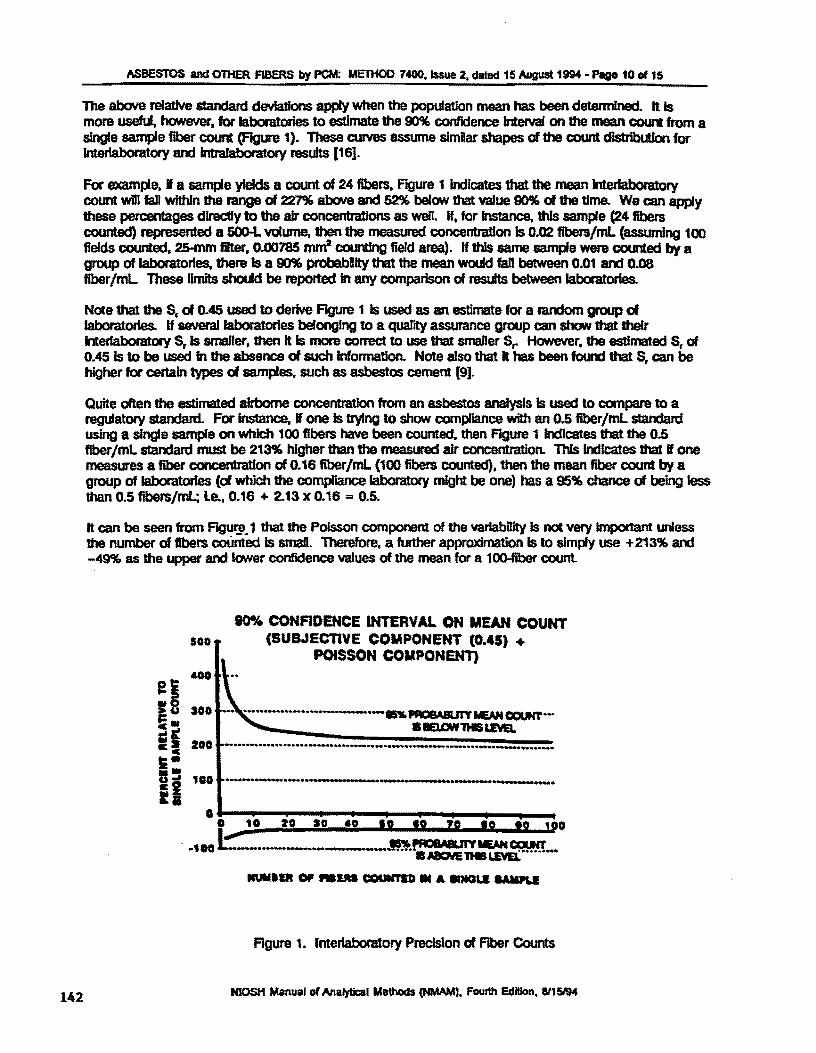
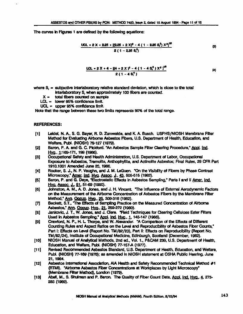
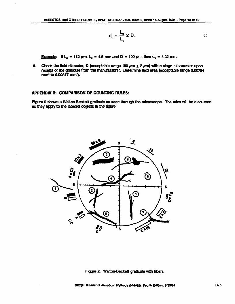