nissan nv 2012-2014, nv (without nav) 2015-up, table of ... · 99-7614 ® 2 nv 2012-2014, nv...
TRANSCRIPT

METRA - The World’s best kits ® metraonline.com
REV.
12/
9/20
16
INST
99-7
614
Installation instructions for part 99-7614
®
CAUTION! All accessories, switches, climate controls panels, and especially air bag indicator lights must be connected before cycling the ignition. Also, do not remove the factory radio with the key in the on position, or while the vehicle is running.
© COPYRIGHT 2016 METRA ELECTRONICS CORPORATION
• ISO DIN radio provision with pocket• ISO DDIN radio provision
• A) Radio housing • B) Radio brackets (C) • C) ISO DDIN trimplate • D) (4) #8 x 3/8” Phillips screws
KIT FEATURES
KIT COMPONENTS
WIRING & ANTENNA CONNECTIONS (sold separately)Wiring Harness: • 70-7552
Antenna Adapter: • 40-NI12
• Panel removal tool • Phillips screwdriverTOOLS REQUIRED
Nissan NV 2012-2014, NV (without NAV) 2015-up,Nissan Quest (without NAV or rear seat entertainment) 2011-2012
99-7614Dash Disassembly
Nissan
– NV 2012-2014 .................................................2-4
– NV 2015-up (without NAV) ...............................2-4
– Quest (without NAV or rear seat entertainment) 2011-2012......................................................5-6
Kit Assembly
– ISO DIN radio provision with pocket .................... 7
– ISO DDIN radio provision ..................................... 7
Table of Contents
BA C D

99-7614
®
2
NV 2012-2014, NV (without NAV) 2015-up
1. Unclip and remove the A/C vent to the right side of the factory radio. (Figure A)
2. Remove the (2) Phillips screws exposed behind vent on radio trim panel. (Figure B)
3. Unclip and remove the left A/C vent next to the instrument display. (Figure C)
4. Unclip the top edge of the knee bolster panel below the steering column and let hang. (Figure D)
Continued on the next page
(Figure A)
(Figure D)(Figure B)
(Figure C)
Dash Disassembly

99-7614
®
5. Unclip the circle trim around the key cylinder.
6. Unclip and remove the gauge cluster trim panel. (Figure E)
7. Remove (2) Phillips screws exposed behind the panel on the left side of the radio trim panel. (Figure F)
8. Unclip and remove the trim panel surrounding the factory radio. (Figure G)
9. Remove (4) Phillips screws securing the radio. (Figure H)
3
(Figure F)
(Figure G)
(Figure H)
(Figure E)
Dash Disassembly (Cont)

99-7614
®
4
Dash Disassembly
(Figure B)
(Figure C)
(Figure D)
(Figure A)
Quest (without NAV or rear seat entertainment) 2011-2012
1. Unclip and remove the panels from the bottom left and right side of the center console. (Figure A)
2. Remove (2) clips per side exposed behind lower panels. (Figure B)
3. Unclip and pull center console toward rear of vehicle.
Note: You do not have to fully remove console. (Figure C)
4. Unclip and remove the trim panel to the left of the shifter housing the start/stop button. (Figure D)
5. Unclip and remove the panel on the end of the passenger side of the dash. (Figure E)
Continued on the next page
(Figure E)

99-7614
®
5
6. Remove (1) Phillips screw from the trim panel above the glove box then unclip and remove the panel. (Figure F)
7. Remove (1) Phillips screw from the cup holder panel then unclip and remove the panel. (Figure G)
Continued on the next page
(Figure F)
(Figure G)
Dash Disassembly (Cont)

99-7614
®
6
8. Remove (2) Phillips screws from the a/c control panel and unclip and let hang. (Figure G)
9. Remove (2) Phillips screws from the bottom of the radio trim panel including the vents then unclip and remove the panel. (Figure G)
10. Remove (4) Phillips screws securing the radio. (Figure H)
(Figure G)
(Figure H)
Dash Disassembly (Cont)

99-7614
®
7
Kit Assembly
ISO DIN radio provision with pocket
1. Remove the metal “DIN” sleeve and trim ring from the aftermarket radio.
2. Secure the radio brackets to the radio housing using the (4) 3/8” Phillips screws provided. (Figure A)
3. Slide the radio into the bracket/housing assembly and secure using the screws supplied with the radio. (Figure B)
4. Locate the factory wiring harness and antenna connector in the dash. Metra recommends using the proper mating adapters from Metra and/or AXXESS.
5. Reassemble the dash in reverse order of disassembly.
ISO DDIN radio provision
1. Remove the brackets from the factory radio.
2. Secure the brackets to the aftermarket radio using the screws supplied with the aftermarket radio. (Figure A)
Note: 99-7614 radio brackets can be used in place of the factory brackets.
3. Locate the factory wiring harness and antenna connector in the dash. Metra recommends using the proper mating adapters from Metra and/or AXXESS.
4. Place the ISO DDIN trim plate on the front of the radio. (Figure B)
5. Reassemble the dash in reverse order of disassembly.
(Figure A) (Figure A)
(Figure B) (Figure B)

METRA - The World’s best kits ® metraonline.com © COPYRIGHT 2016 METRA ELECTRONICS CORPORATION
REV.
12/
9/20
16
INST
99-7
614
KNOWLEDGE IS POWEREnhance your installation and fabrication skills by enrolling in the most recognized and respected mobile electronics school in our industry.Log onto www.installerinstitute.com or call 800-354-6782 for more information and take steps toward a better tomorrow.
Metra recommends MECP certified technicians
Installation instructions for part 99-7614
®
IMPORTANTIf you are having difficulties with the installation of this product, please call our Tech Support line at 1-800-253-TECH. Before doing so, look over the instructions a second time, and make sure the installation was performed exactly as the instructions are stated. Please have the vehicle apart and ready to perform troubleshooting steps before calling.

METRA - The World’s best kits ® metraonline.com
REV.
12/
9/20
16
INST
99-7
614
Instrucciones de instalación para la pieza 99-7614
®
¡PRECAUCIÓN! Todos los accesorios, interruptores, paneles de con-troles de clima y especialmente las luces del indicador de las bolsas de aire deben estar conectados antes ciclar la ignición. Además, no quite el radio de fábrica con la llave en la posición o de encendido ni con el vehículo funcionando.
© COPYRIGHT 2016 METRA ELECTRONICS CORPORATION
• Provisión de radio ISO DIN con bolsillo• Provisión de radio ISO DDIN
• A) Carcasa del radio • B) Soportes de radio (C) • C) ISO DDIN placa de moldura • D) (4) #8 x 3/8” tornillos Phillips
CARACTERÍSTICAS DEL KIT
COMPONENTES DEL KIT
CABLEADO Y CONEXIONES DE ANTENA (se venden por separado)Arnés de cableado: • 70-7552
Adaptador de antena: • 40-NI12
• Herramienta para quitar paneles • Destornillador PhillipsHERRAMIENTAS REQUERIDAS
Nissan NV 2012-2014, NV (sin NAV) 2015-up,Nissan Quest (sin NAV o entretenimiento para el asiento trasero) 2011-2012
99-7614
Indice
BA C D
Desmontaje del tablero
Nissan
– NV 2012-2014 .................................................2-4
– NV 2015-up (sin NAV) ......................................2-4
– Quest (sin NAV o entretenimiento para el asiento trasero) 2011-2012 .........................................5-6
Ensamble del kit
– Provisión de radio ISO DIN con bolsillo ................ 7
– Provisión de radio ISO DDIN ................................ 7
99-7614
®
2
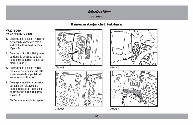
NV 2012-2014, NV (sin NAV) 2015 y mas
1. Desenganche y quite la rejilla del aire acondicionado que está a la derecha del radio de fábrica. (Figura A)
2. Quite los (2) tornillos Phillips que quedan a la vista detrás de la rejilla en el panel de moldura del radio. (Figura B)
3. Desenganche y quite le rejilla del aire acondicionado que está a la izquierda de la pantalla de instrumentos. (Figura C)
4. Desenganche el borde de arriba del panel del refuerzo para rodillas de abajo de la columna de dirección y déjelo colgando. (Figura D)
Continua en la siguiente pagina
(Figura A)
(Figura D)(Figura B)
(Figura C)
Desmontaje del tablero

99-7614
®
5. Desenganche la moldura circular alrededor del cilindro de la llave.
6. Desenganche y quite el panel de la moldura del conjunto de indicadores. (Figura E)
7. Quite los (2) tornillos Phillips que quedan a la vista atrás del panel del lado izquierdo del panel de la moldura del radio. (Figura F)
8. Desenganche y retire el panel de moldura que rodea el radio de fábrica. (Figura G)
9. Retire los (4) tornillos Phillips que sostienen el radio. (Figura H)
3
(Figura F)
(Figura G)
(Figura H)
(Figura E)
Desmontaje del tablero (Cont)

99-7614
®
4
(Figura B)
(Figura C)
(Figura D)
(Figura A)
Quest (sin NAV o entretenimiento para el asiento trasero) 2011-2012
1. Desenganche y quite los paneles de la parte izquierda y derecha de abajo de la consola central. (Figura A)
2. Quite los (2) ganchos de cada lado que quedan a la vista detrás de los paneles de abajo. (Figura B)
3. Desenganche y jale la consola central hacia la parte de atrás del vehículo.
Nota: No es necesario quitar completamente la consola. (Figura C)
4. Desenganche y quite el panel de la moldura del lado izquierdo de la palanca de velocidades donde se encuentra el botón de inicio/paro. (Figura D)
5. Desenganche y quite el panel que está al final del lado del pasajero en el tablero. (Figura E)
Continua en la siguiente pagina
(Figura E)
Desmontaje del tablero

99-7614
®
5
6. Quite (1) tornillo Phillips del panel de la moldura que está arriba de la guantera, luego desenganche y quite el panel. (Figura F)
7. Quite (1) tornillo Phillips del panel de la moldura del portavasos, luego desenganche y quite el panel. (Figura G)
Continua en la siguiente pagina
(Figura F)(Figura G)
Desmontaje del tablero (Cont)

99-7614
®
6
8. Quite los (2) tornillos Phillips del panel de control del aire acondicionado y desenganche y déjelo colgando. (Figura G)
9. Quite los (2) tornillos Phillips de la parte de abajo del panel de la moldura del radio, incluyendo las rejillas, luego desenganche y quite el panel. (Figura G)
10. Quite los (4) tornillos Phillips que sostienen el radio. (Figura H)
(Figura G)
(Figura H)
Desmontaje del tablero (Cont)
99-7614
®
7
Ensamble del kit
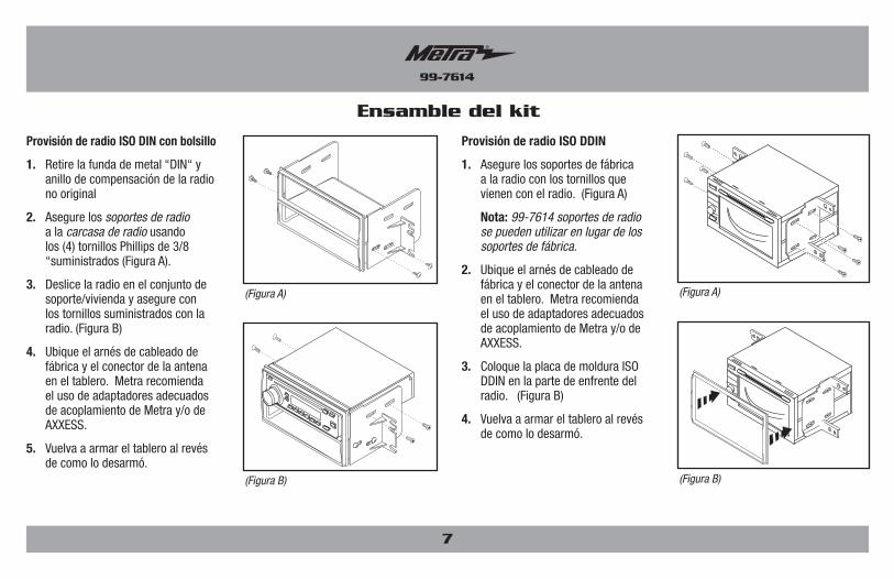
Provisión de radio ISO DIN con bolsillo
1. Retire la funda de metal “DIN“ y anillo de compensación de la radio no original
2. Asegure los soportes de radio a la carcasa de radio usando los (4) tornillos Phillips de 3/8 “suministrados (Figura A).
3. Deslice la radio en el conjunto de soporte/vivienda y asegure con los tornillos suministrados con la radio. (Figura B)
4. Ubique el arnés de cableado de fábrica y el conector de la antena en el tablero. Metra recomienda el uso de adaptadores adecuados de acoplamiento de Metra y/o de AXXESS.
5. Vuelva a armar el tablero al revés de como lo desarmó.
Provisión de radio ISO DDIN
1. Asegure los soportes de fábrica a la radio con los tornillos que vienen con el radio. (Figura A)
Nota: 99-7614 soportes de radio se pueden utilizar en lugar de los soportes de fábrica.
2. Ubique el arnés de cableado de fábrica y el conector de la antena en el tablero. Metra recomienda el uso de adaptadores adecuados de acoplamiento de Metra y/o de AXXESS.
3. Coloque la placa de moldura ISO DDIN en la parte de enfrente del radio. (Figura B)
4. Vuelva a armar el tablero al revés de como lo desarmó.
(Figura A) (Figura A)
(Figura B) (Figura B)
METRA - The World’s best kits ® metraonline.com © COPYRIGHT 2016 METRA ELECTRONICS CORPORATION
REV.
12/
9/20
16
INST
99-7
614
KNOWLEDGE IS POWEREnhance your installation and fabrication skills by enrolling in the most recognized and respected mobile electronics school in our industry.Log onto www.installerinstitute.com or call 800-354-6782 for more information and take steps toward a better tomorrow.
Metra recomienda técnicos con certificación del Programa de Certificación en Electrónica Móvil (Mobile Electronics Certification Program, MECP).
EL CONOCIMIENTO ES PODERMejore sus habilidades de instalación y fabricación inscribiéndose en la escuela de dispositivos electrónicos móviles más reconocida y respetada de nuestra industria. Regístrese en www.installerinstitute.com o llame al 800-354-6782 para obtener más información y avance hacia un futuro mejor.
Instrucciones de instalación para la pieza 99-7614
®
IMPORTANTESi tiene dificultades con la instalación de este producto, llame a nuestra línea de soporte técnico al 1-800-253-TECH. Antes de hacerlo, revise las instrucciones por segunda vez y asegúrese de que la instalación se haya realizado exactamente como se indica en las instrucciones. Por favor tenga el vehículo desarmado y listo para ejecutar los pasos de resolución de problemas antes de llamar.