non-destructive testing of metallic materials using
TRANSCRIPT
Mechanics & Industry 15, 313–321 (2014)c© AFM, EDP Sciences 2014DOI: 10.1051/meca/2014036www.mechanics-industry.org
Mechanics&Industry
Non-destructive testing of metallic materials using passiveand active infrared thermography
P. Bouteille1,a, G. Legros1, H. Walaszek1 and J.L. Bodnar2
1 CETIM, 52, avenue Felix Louat, 60300 Senlis, France2 GRESPI, UFR Sciences Exactes et Naturelles, BP 1039, 51687 Reims Cedex 2, France
Received 7 January 2014, Accepted 15 May 2014
Abstract – In this work, we approach the possibilities of infrared thermography for non-destructive testingof metallic materials. We show that the passive alternative of the method makes it possible to improvedetection of surface defects existing in deep-drawn parts and visible to the naked eye. We then show thatactive infrared thermography, in particular coupled with induction excitation, can replace in certain casesthe magnetic particle inspection, allowing the detection of very fine defects in forged parts. Finally, thestudy of a stepped block confirms the possibilities of active infrared thermography to detect defects notopen to the surface and underlying defects.
Key words: Non destructive testing / infrared thermography / defect detection / metallic samples /industrial samples
1 Introduction
The ever stricter requirements issued by customers of-ten result in the need to carry out a quality inspection on100% of the parts produced, thus requiring industrialiststo implement increasingly sophisticated non-destructivetesting strategies. In order to help industrialists to take upthis challenge, CETIM is performing a continuous techno-logical watch on non-destructive testing techniques underdevelopment and contributes to transfer the most promis-ing techniques to the companies of the mechanical indus-try. Infrared thermography is one of those techniques andtoday it has become the reference method in many appli-cations such as safety, inspection of electrical installationsor inspection of the thermal insulation of buildings. In-frared thermography has some advantages: it is an overallmethod and it has a significant potential for automation.It has already been used successfully for a few years nowfor nondestructive testing of materials with rather slowthermal kinetics (composites, building construction ma-terials, works of art, plastics, etc.). With the technical de-velopments in faster testing equipment and data process-ing tools, it is now possible to contemplate the applicationof this technique to non-destructive testing of materialswith faster thermal kinetics, such as metallic materials.
a Corresponding author: [email protected]
This is the purpose of this study. Non-destructive testingof materials can be either passive or active. In the firstcase, the method consists in analysing the radiation re-sponse given spontaneously by the analysed sample. Thisvariant is more often used to detect surface defects suchas rather large cracks open to the surface. In the secondcase (more suitable for the detection of smaller defectsor defects not open to the surface), the method consistsin applying an external excitation to the tested item andanalysing the photothermal response given by the sam-ple. This method is generally used to detect delaminationin composite materials or separation of plated coatingsin works of art. In the study presented here, we will de-tail the possibilities of both infrared thermography vari-ants for non-destructive testing of metallic materials com-monly used in the mechanical industry. Our presentationis broken down into three parts. First, we will present theprinciple of non-destructive testing of materials using in-frared thermography. Then we will detail the possibilitiesof passive infrared thermography to detect surface defectsin deep-drawn parts. Finally, we will review the possibil-ities of active infrared thermography for the detection ofsmall defects in forged parts, in comparison with mag-netic particle testing, and for the detection of defects ina stepped block.
Article published by EDP Sciences
314 P. Bouteille et al.: Mechanics & Industry 15, 313–321 (2014)
2 Non-destructive testing by infraredthermography
Infrared thermography is a non-destructive testingmethod widely used in the industrial world, for instancefor thermal diagnosis of buildings, for safety or for theinspection of electrical cabinets [1]. The passive variantof infrared thermography consists in acquiring, using athermal camera, the radiation flux naturally emitted bythe examined body [2]. The image obtained, called “ther-mogram”, can therefore reveal an abnormal variation ofthe radiation flux and evidence a defect. This variationmay depend on two physical phenomena: an optical phe-nomenon and a thermal phenomenon. In the first case,the presence of a defect can generate a change in the ra-diation properties of the surface of the analysed sample,thereby allowing the detection of the defect. This hap-pens with cracks open to the surface, for instance. Inthat particular case, the radiation behaviour of the crackcan be compared to that of a micro black body. It gener-ates an apparent emissivity value which can become muchhigher than that of the surface of the analysed sample;this can then generate a radiation flux peak just abovethe defect, thereby allowing its detection [3]. In the sec-ond case (thermal phenomenon), the presence of a defectcan generate some asymmetry in the spatial distributionof temperature, which also leads to detection. This spatialdisturbance of the radiation flux is widely used in med-ical applications of infrared thermography. If the partsto be tested do not spontaneously give information as totheir preservation state, it becomes necessary to disturbthe tested sample and analyse its thermal response soas to collect this information. This is therefore active in-frared thermography [3]. Several disturbance modes canthen be used: the analysed material can be excited op-tically (flash lamps, halogen lamps, laser, etc.), electro-magnetically (eddy currents), mechanically (ultrasounds)or by a hot air flow [4–11]. The selected method, the po-sition of the source and the heating time are dependenton the material to be tested, its thickness and the nature,position and orientation of the expected defect. Further-more, various excitation methods can be implemented: letus mention flash lamp excitation, step heating excitationor harmonic excitation. In order to study fragile materi-als, such as biological materials or works of art, randomexcitations can also be used [12]. Finally, for the selec-tion of the experimental conditions, it is also importantto define the position of the camera and of the excita-tion source with respect to the tested part: camera andsource on the same side of the part (reflection) or on bothsides of the part (transmission) and angle to be providedbetween these different items to prevent spurious reflec-tions [13–20]. All these different possibilities lead to manyways of implementing the active infrared thermographymethod and each way will answer a particular problem.In this work, we have implemented three variants of ac-tive infrared thermography: active infrared thermographywith flash lamp optical excitation, infrared thermographyassociated with laser excitation, and infrared thermogra-phy associated with eddy current excitation (induction).
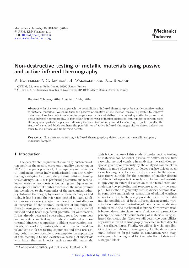
Fig. 1. Thermogram obtained during the study of a soundcar suspension part.
3 Applications of passive infraredthermography for the inspectionof deep-drawn parts
Deep-drawn parts can have various types of defects,among which we may mention cracks or incipient cracks.These defects result from excessive elongation of the ma-terial, and they are likely to adversely affect the mechan-ical characteristics of the part and, therefore, they canembrittle it during its use. During production, chips mayalso migrate in the tool and end up between the tool andthe material to be formed; the surface of the part thenhas a mark. Customers usually do not accept these “cos-metic” defects. As a result, industrialists in this sectorare looking for an on-line inspection method which wouldbe able to detect such defects. Since infrared thermogra-phy has a significant potential for automation, we foundit interesting to take a look at its possibilities for theinspection of deep-drawn parts. For this study, we exam-ined three types of conventional industrial defects: cracksin car suspension parts, incipient cracks and fissures in carcrankcases and, finally, appearance defects in car mount-ing plates caused by chips which migrated. Now let usexamine the results obtained in this scope.
3.1 Detection of cracks in car suspension parts
The first study developed in passive infrared thermog-raphy concerns the detection of cracks in car suspensionparts. These parts are 3 mm thick approximately, andcracks can appear during the parts forming process. Weanalysed sound and defective parts. The results obtainedare presented in Figure 1 for the sound part and in Fig-ure 2 for the defective part. They clearly show that acrack gives a higher radiation signal at the exact locationof the defect, thereby allowing detection.
3.2 Detection of incipient cracks and fissures in carengine crankcases
The second study developed in passive infrared ther-mography concerns the detection of incipient cracks andfissures in car engine crankcases. For that purpose, westudied three coated steel crankcases. The first one is a

P. Bouteille et al.: Mechanics & Industry 15, 313–321 (2014) 315
Fig. 2. Thermogram obtained during the study of a defectivecar suspension part.
Fig. 3. Thermogram obtained during the examination of asound crankcase.
Fig. 4. Thermogram obtained during the examination of acrankcase with an incipient crack.
sound crankcase, the second one has an incipient crackand the last one has a through crack. As the previousresult showed the feasibility of the method, we wantedin this new study to approach the experimental condi-tions encountered at the outlet of a deep-drawing press.For that purpose, we covered the crankcases with a filmof grease to simulate the drawing lubricant. The resultsobtained are presented in Figures 3 to 5. Figure 3 cor-responds to the thermogram obtained during the exam-ination of the sound crankcase. Figure 4 corresponds tothe thermogram obtained during the examination of theincipient crack; it shows a peculiar radiation signatureat the location of the crack. This shows the possibilitiesof passive infrared thermography to detect this type ofdefects in conditions close to those found in a factory.Figure 5 corresponds to the thermogram obtained duringthe examination of the cracked crankcase. Here again, ahigher radiation signal is visible at the location of thedefect, thereby allowing its detection. Finally, the com-parison between Figures 4 and 5, shows that the radia-tion signature of the defect is higher for a deeper defect.
Fig. 5. Thermogram obtained during the examination of acrankcase with a through crack.
Fig. 6. Thermogram obtained during the examination of acar mounting plate exhibiting an appearance defect caused bya migrating chip (chip side).
Fig. 7. Thermogram obtained during the examination of acar mounting plate exhibiting an appearance defect caused bya migrating chip (face opposite to the chip).
This observation is interesting since it can pave the wayfor dimensional characterisation of this type of defects.
3.3 Detection of appearance defects in car mountingplates caused by migrating chips
The third study developed in passive infrared ther-mography concerns the detection of migrating waste incar mounting plates made of steel. This is an appear-ance defect of industrial parts, caused by chips which mi-grated in the tooling. As in the previous cases, Figures 6and 7 show the possibility of detection of this defect, asit changes the surface radiation properties of the part.
The interest of this third study, after laboratory ex-periments, was the possibility to test the passive methodat the end of a production line. This study on an indus-trial site was developed in normal production conditions.
316 P. Bouteille et al.: Mechanics & Industry 15, 313–321 (2014)
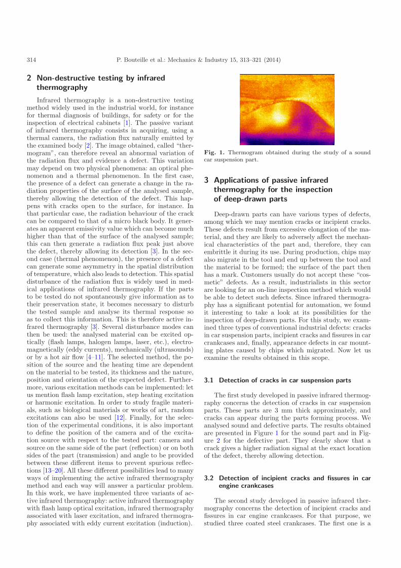
Fig. 8. Experimental device selected for the study.
Fig. 9. Sound part.
Fig. 10. Part exhibiting an appearance defect caused by amigrating chip.
The parts were analysed as they travelled in the produc-tion line; therefore, they were warm and covered in lubri-cant. The infrared camera was installed at press outlet.It continuously shot the parts to be inspected (Fig. 8).
During this measurement campaign, approximatelyone hundred parts were inspected, among whichapproximately ten defective parts. As in the previous case,these defective parts were characterised by an appearancedefect (Figs. 9 and 10).
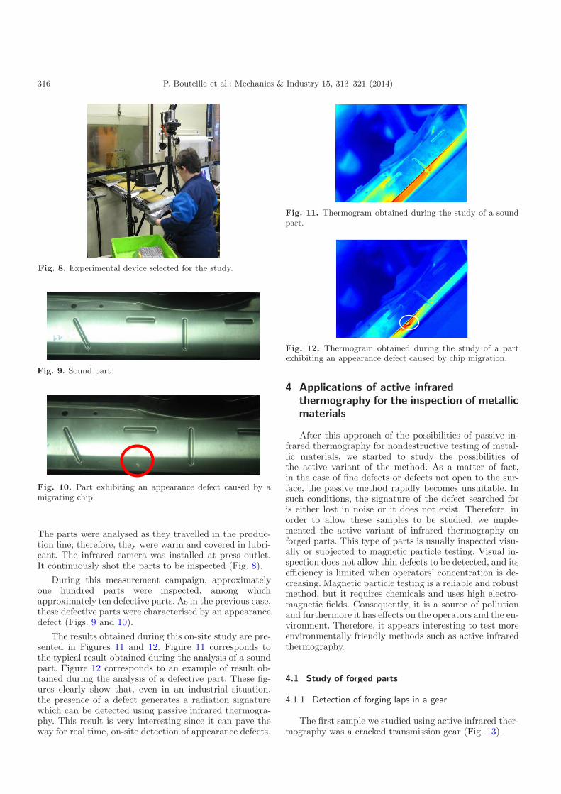
The results obtained during this on-site study are pre-sented in Figures 11 and 12. Figure 11 corresponds tothe typical result obtained during the analysis of a soundpart. Figure 12 corresponds to an example of result ob-tained during the analysis of a defective part. These fig-ures clearly show that, even in an industrial situation,the presence of a defect generates a radiation signaturewhich can be detected using passive infrared thermogra-phy. This result is very interesting since it can pave theway for real time, on-site detection of appearance defects.
Fig. 11. Thermogram obtained during the study of a soundpart.
Fig. 12. Thermogram obtained during the study of a partexhibiting an appearance defect caused by chip migration.
4 Applications of active infraredthermography for the inspection of metallicmaterials
After this approach of the possibilities of passive in-frared thermography for nondestructive testing of metal-lic materials, we started to study the possibilities ofthe active variant of the method. As a matter of fact,in the case of fine defects or defects not open to the sur-face, the passive method rapidly becomes unsuitable. Insuch conditions, the signature of the defect searched foris either lost in noise or it does not exist. Therefore, inorder to allow these samples to be studied, we imple-mented the active variant of infrared thermography onforged parts. This type of parts is usually inspected visu-ally or subjected to magnetic particle testing. Visual in-spection does not allow thin defects to be detected, and itsefficiency is limited when operators’ concentration is de-creasing. Magnetic particle testing is a reliable and robustmethod, but it requires chemicals and uses high electro-magnetic fields. Consequently, it is a source of pollutionand furthermore it has effects on the operators and the en-vironment. Therefore, it appears interesting to test moreenvironmentally friendly methods such as active infraredthermography.
4.1 Study of forged parts
4.1.1 Detection of forging laps in a gear
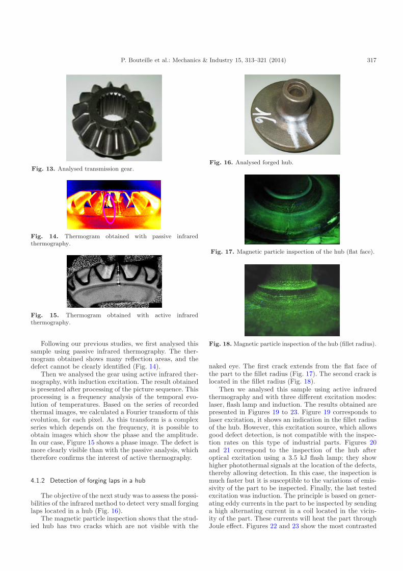
The first sample we studied using active infrared ther-mography was a cracked transmission gear (Fig. 13).
P. Bouteille et al.: Mechanics & Industry 15, 313–321 (2014) 317
Fig. 13. Analysed transmission gear.
Fig. 14. Thermogram obtained with passive infraredthermography.
Fig. 15. Thermogram obtained with active infraredthermography.
Following our previous studies, we first analysed thissample using passive infrared thermography. The ther-mogram obtained shows many reflection areas, and thedefect cannot be clearly identified (Fig. 14).
Then we analysed the gear using active infrared ther-mography, with induction excitation. The result obtainedis presented after processing of the picture sequence. Thisprocessing is a frequency analysis of the temporal evo-lution of temperatures. Based on the series of recordedthermal images, we calculated a Fourier transform of thisevolution, for each pixel. As this transform is a complexseries which depends on the frequency, it is possible toobtain images which show the phase and the amplitude.In our case, Figure 15 shows a phase image. The defect ismore clearly visible than with the passive analysis, whichtherefore confirms the interest of active thermography.
4.1.2 Detection of forging laps in a hub
The objective of the next study was to assess the possi-bilities of the infrared method to detect very small forginglaps located in a hub (Fig. 16).
The magnetic particle inspection shows that the stud-ied hub has two cracks which are not visible with the
Fig. 16. Analysed forged hub.
Fig. 17. Magnetic particle inspection of the hub (flat face).
Fig. 18. Magnetic particle inspection of the hub (fillet radius).
naked eye. The first crack extends from the flat face ofthe part to the fillet radius (Fig. 17). The second crack islocated in the fillet radius (Fig. 18).
Then we analysed this sample using active infraredthermography and with three different excitation modes:laser, flash lamp and induction. The results obtained arepresented in Figures 19 to 23. Figure 19 corresponds tolaser excitation, it shows an indication in the fillet radiusof the hub. However, this excitation source, which allowsgood defect detection, is not compatible with the inspec-tion rates on this type of industrial parts. Figures 20and 21 correspond to the inspection of the hub afteroptical excitation using a 3.5 kJ flash lamp; they showhigher photothermal signals at the location of the defects,thereby allowing detection. In this case, the inspection ismuch faster but it is susceptible to the variations of emis-sivity of the part to be inspected. Finally, the last testedexcitation was induction. The principle is based on gener-ating eddy currents in the part to be inspected by sendinga high alternating current in a coil located in the vicin-ity of the part. These currents will heat the part throughJoule effect. Figures 22 and 23 show the most contrasted

318 P. Bouteille et al.: Mechanics & Industry 15, 313–321 (2014)
Fig. 19. Thermogram obtained during the examination of thehub (laser excitation).
Fig. 20. Thermogram obtained during the examination of theflat face of the forged hub (flash lamp excitation).
Fig. 21. Thermogram obtained during the examination of thefillet radius of the forged hub (flash lamp excitation).
signatures of the methods implemented in this study. Fur-thermore, the implementation of induction excitation iscompatible with the industrial constraints encountered ina forging plant. This study demonstrates that inductionthermography is very interesting to detect micro-cracks.
4.1.3 Detection of cracks in a forged ball joint
Further to this very positive study, we continued ourinvestigations on a forged ball joint (Fig. 24).
The conventional magnetic particle inspection re-vealed the presence of a crack over the entire length ofthe ball joint (Fig. 25).
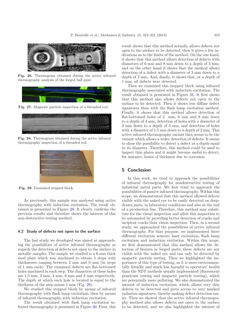
The result obtained with induction excitation ther-mography is presented on Figure 26. It shows a whiteline which corresponds to the photothermal signatureof the crack, further to a 140-ms acquisition which in-cluded 70 ms of induction excitation and 70 ms of cooling.
Fig. 22. Thermogram obtained during the examination of theflat face of the forged hub (induction excitation).
Fig. 23. Thermogram obtained during the examination of thefillet radius of the forged hub (induction excitation).
Fig. 24. Analysed forged ball joint.
Fig. 25. Magnetic particle inspection of the forged ball joint.
The quality of the detection and the short time necessaryfor the test confirm the interest of induction thermogra-phy to inspect forged parts.
4.1.4 Detection of cracks in a threaded rod
Finally, the last industrial sample for which we presentresults is a threaded rod. The magnetic particle inspectionrevealed a longitudinal crack in the part (Fig. 27).
P. Bouteille et al.: Mechanics & Industry 15, 313–321 (2014) 319
Fig. 26. Thermogram obtained during the active infraredthermography analysis of the forged ball joint.
Fig. 27. Magnetic particle inspection of a threaded rod.
Fig. 28. Thermogram obtained during the active infraredthermography inspection of a threaded rod.
Fig. 29. Examined stepped block.
As previously, this sample was analysed using activethermography with induction excitation. The result ob-tained is presented in Figure 28. It clearly confirms theprevious results and therefore shows the interest of thisnon-destructive testing method.
4.2 Study of defects not open to the surface
The last study we developed was aimed at approach-ing the possibilities of active infrared thermography asregards the detection of defects not open to the surface inmetallic samples. The sample we studied is a 6-mm thicksteel plate which was machined to obtain 5 steps withthicknesses ranging between 2 mm and 6 mm (in stepsof 1 mm each). The examined defects are flat-bottomedholes machined in each step. The diameters of these holesare 1.5 mm, 3 mm, 4 mm, 6 mm and 8 mm respectively.The depth at which each hole is located is equal to thethickness of the step minus 1 mm (Fig. 29).
We studied this stepped block by means of infraredthermography with flash lamp excitation, then by meansof infrared thermography with induction excitation.
The result obtained with flash lamp excitation in-frared thermography is presented in Figure 30. First, this
result shows that this method actually allows defects notopen to the surface to be detected, then it gives a few in-dications as to the limits of the method. On the one hand,it shows that this method allows detection of defects withdiameters of 6 mm and 8 mm down to a depth of 5 mm,and on the other hand it shows that the method allowsdetection of a defect with a diameter of 3 mm down to adepth of 2 mm. And, finally, it shows that, at a depth of1 mm, all defects were detected.
Then we examined this stepped block using infraredthermography associated with induction excitation. Theresult obtained is presented in Figure 31. It first showsthat this method also allows defects not open to thesurface to be detected. Then it shows less diffuse defectsignatures than with the flash lamp excitation method.Finally, it shows that this method allows detection offlat-bottomed holes of 4 mm, 6 mm and 8 mm downto a depth of 4 mm, detection of holes with a diameter of3 mm down to a depth of 3 mm, and detection of holeswith a diameter of 1.5 mm down to a depth of 2 mm. Thisactive infrared thermography variant then seems to be thevariant which allows a wider detection of defects. It seemsto show the possibility to detect a defect at a depth equalto its diameter. Therefore, this method could be used toinspect thin plates and it might become useful to detect,for instance, losses of thickness due to corrosion.
5 Conclusion
In this work, we tried to approach the possibilitiesof infrared thermography for nondestructive testing ofindustrial metal parts. We first tried to approach thepossibilities of passive infrared thermography. Within thisscope, we demonstrated that this method allowed defectsvisible with the naked eye to be easily detected on deep-drawn parts, in laboratory conditions and also at the endof a production line. Therefore, this method may substi-tute for the visual inspection and allow this inspection tobe automated by providing better detection of cracks andincipient cracks than vision inspection. Then, in a secondstudy, we approached the possibilities of active infraredthermography. For that purpose, we implemented threedifferent excitation sources: laser excitation, flash lampexcitation and induction excitation. Within this scope,we first demonstrated that this method allows the de-tection of fissures in forged parts; these defects are notvisible with the naked eye and can only be detected bymagnetic particle testing. Then we highlighted the im-portance of this type of testing, as it is more environmen-tally friendly and much less harmful to operators’ healththan the NDT methods usually implemented (fluorescentpenetrant testing and magnetic particle testing), whichare potentially more polluting. We also demonstrated theinterest of induction excitation, which allows very thindefects to be detected and gives access to very markedradiation signatures, thereby making defect detection eas-ier. Then we showed that the active infrared thermogra-phy method also allows defects not open to the surfaceto be detected, and we also highlighted the interest of

320 P. Bouteille et al.: Mechanics & Industry 15, 313–321 (2014)
Fig. 30. Analysis of a stepped block using infrared thermography with flash lamp excitation.
Fig. 31. Analysis of a stepped block using infrared thermography with induction excitation.

P. Bouteille et al.: Mechanics & Industry 15, 313–321 (2014) 321
induction excitation, which has better performance thanflash lamp excitation. Finally we empirically determinedthat the photothermal method made it possible to detecta defect not open to the surface (corrosion type) if itsdepth was lower than its diameter. These results are veryencouraging and need to be completed, for instance bybetter determining the limits of active thermography andassessing the possibility of automation of such a testingprocess. Studies on these subjects are in progress.
References
[1] D. Pajani, Mesure par thermographie infrarouge, Chap. 8– Les applications de la thermographie, p. 331, 1989,ISBN: 2-9504171-0-8
[2] D. Pajani, Mesure par thermographie infrarouge, Chap. 1– Introduction, 1989, p. 11, ISBN: 2-9504171-0-8
[3] X. Maldague, Theory and practice of infrared technologyfor non-destructive testing, Ed. Willey, 2001, ISBN: 0-471-18190-0
[4] J.L. Bodnar, M. Edee, Wear characterization by pho-tothermal radiometry, Wear 196 (1996) 54–59
[5] J.L. Bodnar, M. Edee, C. Menu, R. Besnard, A. Le Blanc,M. Pigeon, J.Y. Sellier, Cracks detection by a movingphotothermal probe, J. Phys. IV 4 (1994) C7-592
[6] H.G. Walther, D. Fournier, J.C. Krapez, M. Luukkala, B.Schmitz, C. Sibilia, H. Stamm, J. Thoen, PhotothermalSteel Hardness Measurements – Results and Perspectives,Anal. Sci. 17 (2001) s158–s160
[7] Th. Zweschper, A. Dillenz, G. Riegert, D. Scherling, G.Busse, Ultrasound excited thermography using frequencymodulated elastic waves, Insight 45 (2003) 178–182
[8] J. Vrana, M. Goldammer, J. Baumann, M. Rothenfusser,W. Arnold, Mechanisms and Models for Crack Detectionwith Induction Thermography, Rev. Prog. QNDE 27(2008) 475–482
[9] H. Mooshofer, M. Goldammer, W. Heine, M.Rothenfusser, J. Bass, E. Lombardo, J. Vrana,Induktionsthermographie zur automatischen Prufungvon Generatorkomponenten, DGZfP-Jahrestagung 2009,Munster, Allemagne, 2009
[10] J. Bamberg, G. Erbeck, G. Zenzinger, EddyTherm:Ein Verfahren zur bildgebenden Rißprufung metallischerBauteile, ZfP-Zeitung 68 (1999) 60−62
[11] G. Riegert, Th. Zweschper, A. Dillenz, G. Busse,Wirbelstromangeregte Lockin-Thermografie – Prinzipund Anwendungen, DACH – Jahrestagung 2004Salzburg, http://www.ndt.net/article/dgzfp04/
papers/v90/v90.htm
[12] J.L. Bodnar, K. Mouhoubi, G. Szatanik-Perrier, J.M.Vallet, V. Detalle, Photothermal thermography appliedto the non-destructive testing of different types of worksof art, IJOT, DOI:10.1007/s10765-012-1301-2
[13] J.L. Bodnar, Controle optique des materiaux par ra-diometrie photothermique aleatoire infrarouge, Revue del’electricite et de l’electronique 2 (2007) 68–74
[14] X. Maldague, Introduction to NDT by active infraredthermography, Mater. Evaluation 6 (2002) 1060−1073
[15] S. Maillard, J. Cadith, Walaszek H., Bodnar J.L., Lathermographie infrarouge active et ses nouvelles appli-cations aux materiaux metalliques, COFREND congressproceedings, Dunkerque, France, 2011
[16] S. Maillard, J. Cadith, G. Legros, P. Bouteille,H. Walaszek, J.L. Bodnar, Controle de materiauxmetalliques par thermographie active, Thermogramcongress proceedings, Chalons en Champagne France,2011
[17] S. Maillard, J. Cadith, D. Eschimese, H. Walaszek, H.Mooshofer, J.C. Candore, J.L. Bodnar, Towards the useof passive and active infrared thermography to inspectmetallic components in the mechanical industry, QIRTcongress proceedings, Laval, Quebec, 2010
[18] S. Maillard, J. Cadith, H. Walaszek, J.L. Bodnar,Controle non destructif de materiaux metalliques parthermographie infrarouge active, Mesures et TechniquesOptiques pour l’Industrie, Lille France, 2011
[19] P. Bouteille, G. Legros, S. Maillard, J. Cadith, J.L.Bodnar, Induction active thermography as an alternativeto magnetic particle inspection, QIRT congress proceed-ing, Naples, Italie, 2012
[20] S. Maillard, J. Cadith, P. Bouteille, G. Legros, J.L.Bodnar, V. Detalle, Non-destructive testing of forgedmetallic materials by active infrared thermography,IJOT, DOI:10.1007/s10765-012-1275-0