non sono ammesse modifiche dell’organismo notifica · components certificates have been carried...
TRANSCRIPT
Documento riservato. Ogni modifica deve essere sottoposta all’organismo notificato. Confidential document. Any change must be submitted to the notified authority. Data / Date:
Scritto/Written by AF Verificato/Verified NM
30/07/2002
Concorezzo (MI) Italia
Istruzioni ATEX / ATEX Instructions
IS-001/5 Avviamento, comando e protezione motori serie MU e EJB IS-001/5 Starting, control and motor protection unit device s series EJB and MU
Approvato/Approved FF foglio 1 di 11 sheet 1 of 11
ATEX Instructions: Starting, control and motor protection unit devices series EJB and MU ATEX II 2G, II 2(1)G, I M2 EEx d IIB T5, EEx d[ia] IIB T5, EEx d I 150°C, EEx d[ia] I 150°C Test Certificate CESI 03 ATEX 012
Istruzioni ATEX: Dispositivi d’avviamento, comando e protezione motori serie EJB e MU ATEX II 2G, II 2(1)G, I M2 EEx d IIB T5, EEx d[ia] IIB T5, EEx d I 150°C, EEx d[ia] I 150°C Certif. di Conformità CESI 03 ATEX 012
DOCUMENTO ALLEGATO AL CERTIFICATO . . . . . . . . . . . .
Non sono ammesse modifiche senza l’approvazione
dell’Organismo Notificato

Documento riservato. Ogni modifica deve essere sottoposta all’organismo notificato. Confidential document. Any change must be submitted to the notified authority. Data / Date:
Scritto/Written by AF Verificato/Verified NM
30/07/2002
Concorezzo (MI) Italia
Istruzioni ATEX / ATEX Instructions
IS-001/5 Avviamento, comando e protezione motori serie MU e EJB IS-001/5 Starting, control and motor protection unit device s series EJB and MU
Approvato/Approved FF foglio 2 di 11 sheet 2 of 11
Instructions for ATEX usage General usage The safety measures and the apparatuses used on starting, control and motor protection unit devices series EJB and MU installation, use and maintenance place must follow the specific instructions described in this manual and the applicable equipment rules (equipment basic rule CEI 64-8 and/or those of the installation location). It must also follow the additional rules EN 60079-14 and EN 60079-17 for hazardous locations with explosion danger due to the presence of gas for what concerns installation and tests and IEC 60079-19 for what concerns the maintenance and repair (unless otherwise indicated).
Istruzioni per l’uso ATEX Generalità Le misure di sicurezza e le apparecchiature utilizzate sul posto d’installazione, esercizio e manutenzione delle unità d’avviamento, comando e protezione motori serie EJB e MU devono seguire le istruzioni specifiche contenute in questo manuale e le norme impiantistiche applicabili (norma base impiantistica CEI 64-8 e/o quella del luogo d’installazione) e quelle aggiuntive nei luoghi con pericolo d’esplosione per la presenza di gas EN 60079-14 ed EN 60079-17, per quanto riguarda le installazioni e le verifiche, e la IEC 60079-19 per quanto riguarda la manutenzione e riparazione (salvo diversamente specificato).
Usage These rules are applied to the starting, control and motor protection unit device series EJB and MU with the following described features. The containers series EJB and MU have been studied and manufactured following the regulations of the European rules EN 50014, EN 50018 and in conformity to the ATEX Directive 94/9/CE. These instructions have been conceived for technical users who have already a background of technical experience on the use and start-up of electrical machinery and equipment in places with explosion danger, and have been already trained and informed accordingly.
Applicabilità Queste regole si applicano alle unità d’avviamento, comando e protezione motori serie EJB e MU con le caratteristiche descritte nel seguito. Le custodie serie EJB e MU, sono state progettate e realizzate secondo le prescrizioni delle norme europee EN 50014, EN 50018, e in conformità alla Direttiva ATEX 94/9/CE. Queste istruzioni sono state concepite per installatori ed utilizzatori aventi già esperienza tecnica di base sull’utilizzo e la messa in servizio d’impianti e macchinario elettrico in luogo con pericolo d’esplosione ed essendone stati idoneamente formati ed informati.
Instructions Manual These instructions are supplied complete with drawing of dimensions and engineering, technical datas necessary to perfom a correct installation and connection. Refer to the same for detailed instructions.
Documentazione d’uso Queste istruzioni sono corredate da disegno d’ingombro ed ingegneria, compresi i dati tecnici necessari per effettuare l’installazione correttamente ed il collegamento. Riferirsi pertanto ad essi per le istruzioni relative.

Documento riservato. Ogni modifica deve essere sottoposta all’organismo notificato. Confidential document. Any change must be submitted to the notified authority. Data / Date:
Scritto/Written by AF Verificato/Verified NM
30/07/2002
Concorezzo (MI) Italia
Istruzioni ATEX / ATEX Instructions
IS-001/5 Avviamento, comando e protezione motori serie MU e EJB IS-001/5 Starting, control and motor protection unit device s series EJB and MU
Approvato/Approved FF foglio 3 di 11 sheet 3 of 11
Usage Limitation The containers series EJB and MU are manufactured in accordance to EEx d IIC T5 protection (the MU are also EEx d I 150°C) Both containers can accept intrinsic safety barriers to interface with equipments in Zone 0. The protection mode will be mixed EEx d(ia) IIB and EEx d(ia) I. The protection level covering every single box is indicated on the certification and rating. Furthermore, they have a protection degree IP65, in accordance with the features showed in the specific certificate. The limit temperature of usage is T5 that is to say ≤100°C. Rating and ATEX marking All the containers series MU and EJB are provided of indelible and enduring plates, fixed to the body of the containers. The plates show the following datas:
- Container usage; - Name and address of the manufacturer; - Series indication and container size; EJB
or MU followed by the size and the suffix /I for the group I;
- Serial number/year of manufacturing; - Voltage, currents and powers.
The plate shows also the following ATEX marking:
- EEx d IIB T5, EEx d I 150°C EEx d(ia)IIB T5, EEx d(ia)I 150°C;
- Category II 2 G, II 2(1) G, I M2; - Authority reference for the check-up; - Number of the certificate;
Indicating the containers series EJB and MU with the above mentioned informations, AD Viganò certifies under its responsability that the containers are manufactured at a “state of art” for what concerns safety, and are in accordance to applicable CE Directives and that verifications and individual tests, as required, and indicated on the components certificates have been carried out with positive result.
Limiti d’utilizzo Le custodie serie EJB e MU sono realizzate secondo il modo di protezione EEx d IIB T5, le MU anche EEx d I 150°C. Entrambe le custodie possono ospitare barriere a sicurezza intrinseca per interfacciarsi con apparecchiature in zona 0, il modo di protezione sarà di tipo misto EEx d(ia) IIB e EEx d(ia) I. Il modo di protezione relativo ad ogni singola scatola è riportato sulla targa dati e di certificazione. Inoltre sono dotate di un grado di protezione IP65, rispettando le caratteristiche indicate nel relativo certificato. La temperatura limite d’utilizzo è di T5 vale a dire ≤100°C. Targa dati e marcatura ATEX Tutte le custodie della serie MU e EJB sono dotate di targhe indelebili e durevoli, fissate al corpo della cassetta. La targa riporta i seguenti dati:
- Destinazione d’uso della custodia; - Nome ed indirizzo del fabbricante; - Indicazione della serie e della
grandezza della custodia, EJB o MU seguita dal numero della grandezza e dal suffisso /I per il gruppo I;
- Matricola/anno di costruzione; - Tensioni, correnti e potenze;
La targa riporta la seguente marcatura ATEX:
- EEx d IIB T5, EEx d I 150°C EEx d(ia)IIB T5, EEx d(ia)I 150°C;
- Categoria II 2 G, II 2(1) G, I M2; - Numero dell’organismo incaricato
della sorveglianza; - Il numero di certificato;
Contrassegnando custodie serie EJB e MU con gli elementi sopraccitati, AD Viganò attesta sotto la propria responsabilità, che le custodie sono state costruite a regola d’arte quanto concerne la sicurezza, che sono conformi alle Direttive CE applicabili e che le verifiche e prove individuali prescritte ed indicate sul certificato del componente n° CESI 02 ATEX 012U sono state eseguite con esito positivo.
Documento riservato. Ogni modifica deve essere sottoposta all’organismo notificato. Confidential document. Any change must be submitted to the notified authority. Data / Date:
Scritto/Written by AF Verificato/Verified NM
30/07/2002
Concorezzo (MI) Italia
Istruzioni ATEX / ATEX Instructions
IS-001/5 Avviamento, comando e protezione motori serie MU e EJB IS-001/5 Starting, control and motor protection unit device s series EJB and MU
Approvato/Approved FF foglio 4 di 11 sheet 4 of 11
Installation places The containers series EJB are to be considered group II of electrical equipments, therefore directed to be used in surface plants (not underground and/or mine). The containers series MU are to be considered group I and group II electrical construction which are intended to be used both on surface and underground and/or mine plants (only if manufactured in cast iron, aluminum boxes are not acceptable for group I), both are intended for places classified as Zone 1 or Zone 2 in accordance to EN 60079-10 and IEC 61241-10.21. Installers and users are always responsible for the accordance on the characteristics of the places where installed the equipments and to the limits as above.
Luoghi d’installazione Le custodie serie EJB sono da considerarsi costruzioni elettriche del gruppo II, quindi destinate ad essere utilizzate in impianti di superficie (non in sotterraneo e/o miniera). Le custodie serie MU sono costruzioni elettriche del gruppo II e del gruppo I quindi destinate ad essere utilizzate sia in impianti di superficie sia sotterraneo e/o miniera (solo se realizzate in ghisa, non sono ammesse custodie in alluminio per gruppo I), entrambe sono destinate in luoghi classificati come Zona 1 o Zona 2 secondo le norme EN 60079-10 ed IEC 61241-10.21. L’installatore e l’utilizzatore sono sempre responsabili della rispondenza delle caratteristiche dei luoghi d’installazione ai limiti ed alle caratteristiche di cui sopra.
Manufacturing characteristics and rules. The containers series EJB and MU are made of a body and a cover in different sizes, used in accordance to the number of electrical equipments and/or terminals to be inserted and to the inputs of connection cables. They are normally manufactured in different variables both in dimensions and placement of the internal equipments. Here below are some configurations:
Caratteristiche e disposizioni costruttive. Le custodie serie EJB e MU sono costituite da un corpo ed un coperchio previsti in diverse dimensioni, utilizzati secondo le apparecchiature elettriche e morsetti da inserire e delle entrate di cavo per i collegamenti. Sono realizzate normalmente in diverse varianti sia dimensionali che per la disposizione delle apparecchiature interne. Di seguito sono riportate alcune configurazioni:

Documento riservato. Ogni modifica deve essere sottoposta all’organismo notificato. Confidential document. Any change must be submitted to the notified authority. Data / Date:
Scritto/Written by AF Verificato/Verified NM
30/07/2002
Concorezzo (MI) Italia
Istruzioni ATEX / ATEX Instructions
IS-001/5 Avviamento, comando e protezione motori serie MU e EJB IS-001/5 Starting, control and motor protection unit device s series EJB and MU
Approvato/Approved FF foglio 5 di 11 sheet 5 of 11
Potenza dissipabile all'interno delle custodie Power dissipation inside the enclosures
Custodia Enclosure
Potenza W Power W
Custodia Enclosure
Potenza W Power W
EJB1 30 MU * 30 EJB2 50 MU 0 30 EJB3 100 MU 1 * 30 EJB3A 100 MU 2 50 EJB4 200 MU 3 * 50 EJB4A 200 MU 4CB 50 EJB5 250 MU 4 * 50 EJB5A 300 MU 5CB 50 EJB5B 300 MU 5* 100 EJB6 300 MU 6CB 100 EJB6A 350 MU 6 * 200 EJB7 350 MU 7CB 250 EJB7A 350 MU 7 * 300 EJB8 400 MU 8CB 300 EJB8A 400 MU 8 * 300 MU 9 * 350 MU 9L 400
MU 9Q 500 * custodie gruppo I
* group I enclosures

Documento riservato. Ogni modifica deve essere sottoposta all’organismo notificato. Confidential document. Any change must be submitted to the notified authority. Data / Date:
Scritto/Written by AF Verificato/Verified NM
30/07/2002
Concorezzo (MI) Italia
Istruzioni ATEX / ATEX Instructions
IS-001/5 Avviamento, comando e protezione motori serie MU e EJB IS-001/5 Starting, control and motor protection unit device s series EJB and MU
Approvato/Approved FF foglio 6 di 11 sheet 6 of 11
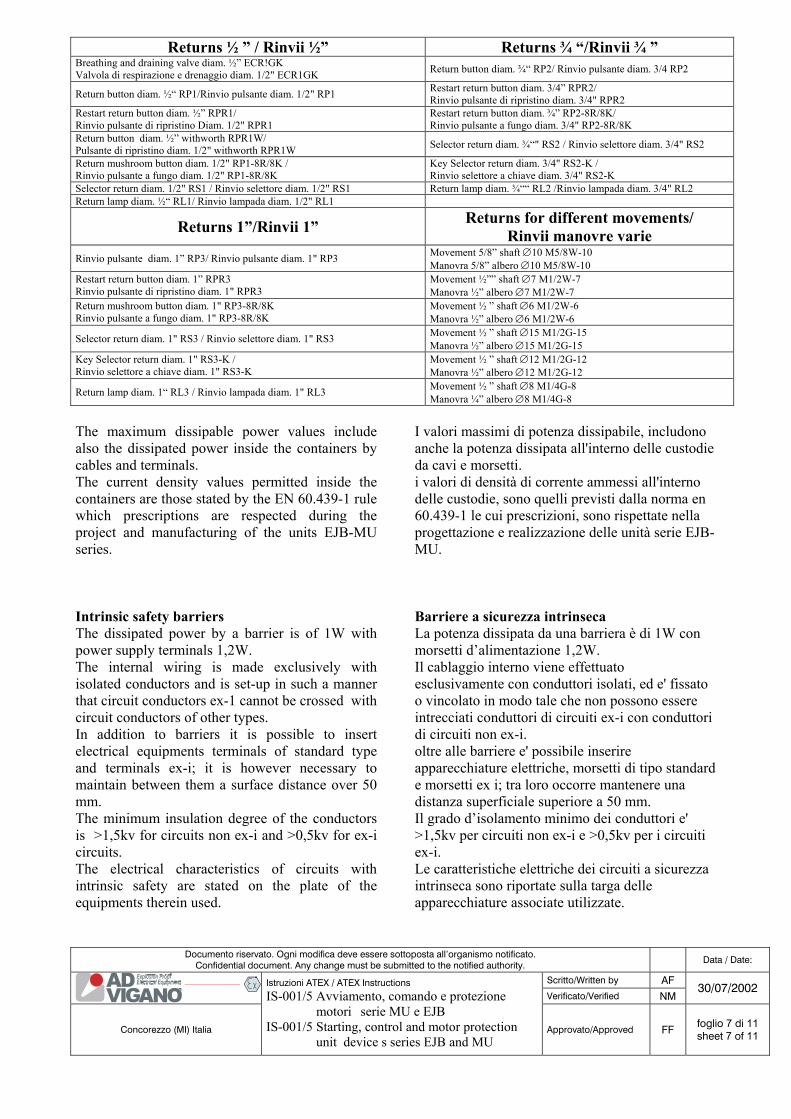
Controls: For the switches and isolators control, only the following certified returns with their own containers can be used:
Comandi: Per il comando degli interruttori e sezionatori, si possono utilizzare esclusivamente i seguenti rinvii certificati con le custodie:
Documento riservato. Ogni modifica deve essere sottoposta all’organismo notificato. Confidential document. Any change must be submitted to the notified authority. Data / Date:
Scritto/Written by AF Verificato/Verified NM
30/07/2002
Concorezzo (MI) Italia
Istruzioni ATEX / ATEX Instructions
IS-001/5 Avviamento, comando e protezione motori serie MU e EJB IS-001/5 Starting, control and motor protection unit device s series EJB and MU
Approvato/Approved FF foglio 7 di 11 sheet 7 of 11
Returns ½ ” / Rinvii ½” Returns ¾ “/Rinvii ¾ ” Breathing and draining valve diam. ½” ECR!GK Valvola di respirazione e drenaggio diam. 1/2" ECR1GK Return button diam. ¾“ RP2/ Rinvio pulsante diam. 3/4 RP2
Return button diam. ½“ RP1/Rinvio pulsante diam. 1/2" RP1 Restart return button diam. 3/4” RPR2/ Rinvio pulsante di ripristino diam. 3/4" RPR2
Restart return button diam. ½” RPR1/ Rinvio pulsante di ripristino Diam. 1/2" RPR1
Restart return button diam. ¾” RP2-8R/8K/ Rinvio pulsante a fungo diam. 3/4" RP2-8R/8K
Return button diam. ½” withworth RPR1W/ Pulsante di ripristino diam. 1/2" withworth RPR1W Selector return diam. ¾“" RS2 / Rinvio selettore diam. 3/4" RS2
Return mushroom button diam. 1/2" RP1-8R/8K / Rinvio pulsante a fungo diam. 1/2" RP1-8R/8K
Key Selector return diam. 3/4" RS2-K / Rinvio selettore a chiave diam. 3/4" RS2-K
Selector return diam. 1/2" RS1 / Rinvio selettore diam. 1/2" RS1 Return lamp diam. ¾““ RL2 /Rinvio lampada diam. 3/4" RL2 Return lamp diam. ½“ RL1/ Rinvio lampada diam. 1/2" RL1
Returns 1”/Rinvii 1” Returns for different movements/ Rinvii manovre varie
Rinvio pulsante diam. 1” RP3/ Rinvio pulsante diam. 1" RP3 Movement 5/8” shaft ∅10 M5/8W-10 Manovra 5/8” albero ∅10 M5/8W-10
Restart return button diam. 1” RPR3 Rinvio pulsante di ripristino diam. 1" RPR3
Movement ½”” shaft ∅7 M1/2W-7 Manovra ½” albero ∅7 M1/2W-7
Return mushroom button diam. 1" RP3-8R/8K Rinvio pulsante a fungo diam. 1" RP3-8R/8K
Movement ½ ” shaft ∅6 M1/2W-6 Manovra ½” albero ∅6 M1/2W-6
Selector return diam. 1" RS3 / Rinvio selettore diam. 1" RS3 Movement ½ ” shaft ∅15 M1/2G-15 Manovra ½” albero ∅15 M1/2G-15
Key Selector return diam. 1" RS3-K / Rinvio selettore a chiave diam. 1" RS3-K
Movement ½ ” shaft ∅12 M1/2G-12 Manovra ½” albero ∅12 M1/2G-12
Return lamp diam. 1“ RL3 / Rinvio lampada diam. 1" RL3 Movement ½ ” shaft ∅8 M1/4G-8 Manovra ¼” albero ∅8 M1/4G-8
The maximum dissipable power values include also the dissipated power inside the containers by cables and terminals. The current density values permitted inside the containers are those stated by the EN 60.439-1 rule which prescriptions are respected during the project and manufacturing of the units EJB-MU series.
I valori massimi di potenza dissipabile, includono anche la potenza dissipata all'interno delle custodie da cavi e morsetti. i valori di densità di corrente ammessi all'interno delle custodie, sono quelli previsti dalla norma en 60.439-1 le cui prescrizioni, sono rispettate nella progettazione e realizzazione delle unità serie EJB-MU.
Intrinsic safety barriers The dissipated power by a barrier is of 1W with power supply terminals 1,2W. The internal wiring is made exclusively with isolated conductors and is set-up in such a manner that circuit conductors ex-1 cannot be crossed with circuit conductors of other types. In addition to barriers it is possible to insert electrical equipments terminals of standard type and terminals ex-i; it is however necessary to maintain between them a surface distance over 50 mm. The minimum insulation degree of the conductors is >1,5kv for circuits non ex-i and >0,5kv for ex-i circuits. The electrical characteristics of circuits with intrinsic safety are stated on the plate of the equipments therein used.
Barriere a sicurezza intrinseca La potenza dissipata da una barriera è di 1W con morsetti d’alimentazione 1,2W. Il cablaggio interno viene effettuato esclusivamente con conduttori isolati, ed e' fissato o vincolato in modo tale che non possono essere intrecciati conduttori di circuiti ex-i con conduttori di circuiti non ex-i. oltre alle barriere e' possibile inserire apparecchiature elettriche, morsetti di tipo standard e morsetti ex i; tra loro occorre mantenere una distanza superficiale superiore a 50 mm. Il grado d’isolamento minimo dei conduttori e' >1,5kv per circuiti non ex-i e >0,5kv per i circuiti ex-i. Le caratteristiche elettriche dei circuiti a sicurezza intrinseca sono riportate sulla targa delle apparecchiature associate utilizzate.

Documento riservato. Ogni modifica deve essere sottoposta all’organismo notificato. Confidential document. Any change must be submitted to the notified authority. Data / Date:
Scritto/Written by AF Verificato/Verified NM
30/07/2002
Concorezzo (MI) Italia
Istruzioni ATEX / ATEX Instructions
IS-001/5 Avviamento, comando e protezione motori serie MU e EJB IS-001/5 Starting, control and motor protection unit device s series EJB and MU
Approvato/Approved FF foglio 8 di 11 sheet 8 of 11
Certificate n°/ N° Certificato Manufacturer and Model/ Produttore e Modello Protection/Protezione
DMT 01 ATEX E 042 X GM International series E10..; D10.. galvanic insulator Isolatore galvanico della GM International serie E10.. ; D10.. [EEx ia] IIC-IIA-IIB, II (1)G, I M2
BAS 00 ATEX 7216 Pepperl + Fuchs series KFD2-SD-EX1.48 barriers certificate Certificato barriere Pepperl + Fuchs serie KFD2-SD-EX1.48 [EEx ia] IIC, II (1)GD
PTB 00 ATEX 2080 Pepperl + Fuchs series KFD2-SR2-EX1.W barriers certificate Certificato barriere Pepperl + Fuchs serie KFD2-SR2-EX1.W [EEx ia] IIC, II (1)GD
BAS 99 ATEX 7060 Pepperl + Fuchs series KFD2-STC4-EX1 barriers certificate Certificato barriere Pepperl + Fuchs serie KFD2-STC4-EX1 [EEx ia] IIC II (1)G
BAS 99 ATEX 7025 Pepperl + Fuchs series KFD2-STC4-EX2 barriers certificate Certificato barriere Pepperl + Fuchs serie KFD2-STC4-EX2 [EEx ia] IIC, II (1) GD
CESI 02 ATEX 136 Pepperl + Fuchs Elcon series µZ600 zener barriers Barriere zener Pepperl + Fuchs Elcon serie µZ600 [Eex ia] IIC
CESI 02 ATEX 093 Pepperl + Fuchs Elcon series IS890 galvanic insulator Isolatore galvanico Pepperl + Fuchs Elcon serie IS890 [EEx ia] IIC, II (1)GD
CESI 02 ATEX 089 Pepperl + Fuchs Elcon series HiD2000 galvanic insulator Isolatore galvanico Pepperl + Fuchs Elcon serie HiD2000 [EEx ia] IIC
PTB 00 ATEX 2082 Pepperl + Fuchs Elcon series KF…-SR2… galvanic insulator Isolatore galvanico della Pepperl + Fuchs serie KF…-SR2… [EEx ia] IIC, II (1)GD
PTB 00 ATEX 035 Pepperl + Fuchs Elcon series KFD2 galvanic insulator Isolatore galvanico della Pepperl + Fuchs serie KFD2… [EEx ia] IIC, II (1)GD
BAS 99 ATEX 7285 BAS 99 ATEX 7287
Measurement Technology Ltd. Series MTL7000 zener barriers Barriere zener della Measurement Technology Ltd. Serie MTL7000
[EEx ia] IIC, II (1)G [EEx ia] IIB, II (1)G
BAS 01 ATEX 7144 BAS 01 ATEX 7145 BAS 01 ATEX 7146 BAS 01 ATEX 7147 BAS 01 ATEX 7152 BAS 98 ATEX 2227 BAS 99 ATEX 7069 BAS 99 ATEX 7085 BAS 98 ATEX 136
Measurement Technology Ltd. Series MTL5000 galvanic insulator Isolatore galvanico della measurement Technology Ltd. Serie MTL5000
[EEx ia] IIC, II (1)GD [EEx ia] IIC, II (1)GD [EEx ia] IIC, II (1)GD [EEx ia] IIC, II (1)GD [EEx ia] IIC, II (1)GD [EEx ia] IIC, II (1)G [EEx ia] IIC, II (1)G [EEx ia] IIC, II (1)G [EEx ia] IIC, II (1)G
BAS 01 ATEX 7202 BAS 01 ATEX 7203
Measurement Technology Ltd. Series MTL700 ML700P zener barriers Barriere zener della measurement Technology Ltd. Serie MTL700 ML700P
[EEx ia] IIC, II (1)GD [EEx ia] IIB, II (1)GD
BAS 01 ATEX 7162 BAS 01 ATEX 7163 BAS 01 ATEX 7164
Measurement Technology Ltd. Series MTL4000 galvanic insulator Isolatore galvanico della measurement Technology Ltd. Serie MTL4000
[EEx ia] IIC, II (1)GD [EEx ia] IIB, II (1)GD [EEx ia] IIB, II (1)GD
BAS 01 ATEX 7217 BAS 01 ATEX 7218
Measurement Technology Ltd. Series MTL7700 zener barriers Barriere zener della measurement Technology Ltd. Serie MTL7700
[EEx ia] IIC, II (1)G [EEx ia] IIB, II (1)G
IP Protection degree The minimum protection degree from accessing of solid bodies and external liquids is IP 65 as per EN 60529 rule, and verified by the testing laboratory as indicated in the certificate n° CESI 02 ATEX 012U
Grado di protezione IP Il grado minimo di protezione dall’accesso di corpi solidi e liquidi esterni è IP 65 secondo la norma EN 60529, e verificato dal laboratorio di prova, come indicato nel certificato n° CESI 02 ATEX 012U.
Electrical Features Max Nominal current from 0 to 660 V ac-dc Nominal current from 7,5 to 630 A Nominal frequency 50 – 60 Hz Composable terminal sections from 2,5 to 70 mm2
Caratteristiche elettriche Tensione nominale massima da 0 a 660V ac-dc Corrente nominale da 7,5 a 630 A Frequenza nominale 50 – 60 Hz Sezioni morsetti componibili da 2,5 a 70 mm2
Buttons Pulsanti
48 VAC-50/60 Hz-10A, 110 VAC-50/60 Hz-8A 220 VAC-50/60 Hz-5A, 380 VAC-50/60 Hz-3A, 48 VDC-5A, 110 VDC-2,5A, 220 VDC-1A
Selectors Selettori
115 VAC-50/60 Hz-10A, 250 VAC-50/60 Hz-6A, 30 VDC-20A
Signalling Segnalatori
24V-5W, 110V-7,5W, 220V-12,5W
ManipulatorsManipolatori
380 VAC / 440 VDC-10A, 110-7,5W, 220V-12,5W
Documento riservato. Ogni modifica deve essere sottoposta all’organismo notificato. Confidential document. Any change must be submitted to the notified authority. Data / Date:
Scritto/Written by AF Verificato/Verified NM
30/07/2002
Concorezzo (MI) Italia
Istruzioni ATEX / ATEX Instructions
IS-001/5 Avviamento, comando e protezione motori serie MU e EJB IS-001/5 Starting, control and motor protection unit device s series EJB and MU
Approvato/Approved FF foglio 9 di 11 sheet 9 of 11
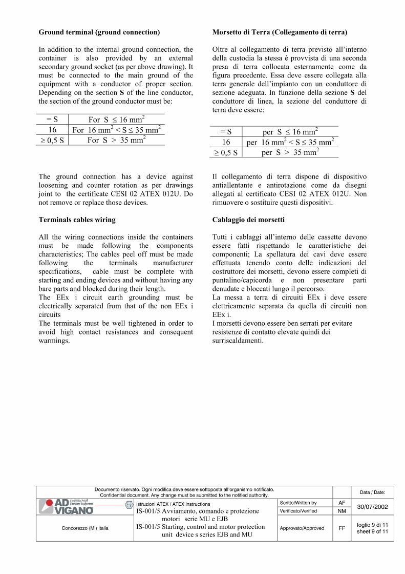
Ground terminal (ground connection) In addition to the internal ground connection, the container is also provided by an external secondary ground socket (as per above drawing). It must be connected to the main ground of the equipment with a conductor of proper section. Depending on the section S of the line conductor, the section of the ground conductor must be:
= S For S ≤ 16 mm2 16 For 16 mm2 < S ≤ 35 mm2
≥ 0,5 S For S > 35 mm2
Morsetto di Terra (Collegamento di terra) Oltre al collegamento di terra previsto all’interno della custodia la stessa è provvista di una seconda presa di terra collocata esternamente come da figura precedente. Essa deve essere collegata alla terra generale dell’impianto con un conduttore di sezione adeguata. In funzione della sezione S del conduttore di linea, la sezione del conduttore di terra deve essere:
= S per S ≤ 16 mm2 16 per 16 mm2 < S ≤ 35 mm2
≥ 0,5 S per S > 35 mm2
The ground connection has a device against loosening and counter rotation as per drawings joint to the certificate CESI 02 ATEX 012U. Do not remove or replace those devices.
Il collegamento di terra dispone di dispositivo antiallentante e antirotazione come da disegni allegati al certificato CESI 02 ATEX 012U. Non rimuovere o sostituire questi dispositivi.
Terminals cables wiring All the wiring connections inside the containers must be made following the components characteristics; The cables peel off must be made following the terminals manufacturer specifications, cable must be complete with starting and ending devices and without having any bare parts and blocked during their length. The EEx i circuit earth grounding must be electrically separated from that of the non EEx i circuits The terminals must be well tightened in order to avoid high contact resistances and consequent warmings.
Cablaggio dei morsetti Tutti i cablaggi all’interno delle cassette devono essere fatti rispettando le caratteristiche dei componenti; La spellatura dei cavi deve essere effettuata tenendo conto delle indicazioni del costruttore dei morsetti, devono essere completi di puntalino/capicorda e non presentare parti denudate e bloccati lungo il percorso. La messa a terra di circuiti EEx i deve essere elettricamente separata da quella di circuiti non EEx i. I morsetti devono essere ben serrati per evitare resistenze di contatto elevate quindi dei surriscaldamenti.
Documento riservato. Ogni modifica deve essere sottoposta all’organismo notificato. Confidential document. Any change must be submitted to the notified authority. Data / Date:
Scritto/Written by AF Verificato/Verified NM
30/07/2002
Concorezzo (MI) Italia
Istruzioni ATEX / ATEX Instructions
IS-001/5 Avviamento, comando e protezione motori serie MU e EJB IS-001/5 Starting, control and motor protection unit device s series EJB and MU
Approvato/Approved FF foglio 10 di 11 sheet 10 of 11
Verifications and maintenance The verification and maintenance of the electrical equipments in places with explosion dangers must be performed following the instructions of EN 60079-17 rule.: - The cover must be securely locked to the
bottom. - The surface of the explosion-proof joint
between body and cover must not be modified, and no gasket must be inserted otherwise it will reduce the useful length of flame lamination. During the cover opening be carefull to not damage or scratch the flat coupling surface. This surface must be well cleaned, in order to avoid corrosion and to guarantee the minimum mechanical protection degree IP 45. To avoid water entry and in order to guarantee the IP 65 protection, we declared, it is necessary to use a thin coat of silicon grease; as indicated on the plates fixed to the cover. The grease must be replaced at each cover opening.
- Check the terminals locking to verify they are not loosening
- Replacement of rubber washers and the parts where cables are entering must be made with identical components of those supplied by the manufacturer in order to guarantee the protection maintenance.
.Verifiche e manutenzione Le verifiche e la manutenzione degli impianti elettrici nei luoghi con pericolo d’esplosione devono essere eseguite secondo i criteri della norma EN 60079-17. - Il coperchio deve essere serrato a fondo. - Le superfici del giunto a prova d’esplosione tra
corpo e coperchio, corpo non deve essere lavorato né deve essere introdotta una guarnizione di tenuta, altrimenti si riduce la lunghezza utile di laminazione della fiamma; nelle operazioni d’apertura del coperchio prestare attenzione a non danneggiare o rigare la superficie piana d’accoppiamento. Tale superficie deve essere mantenuta pulita, per evitare la corrosione e per garantire il mantenimento del grado di protezione meccanico minimo IP 45. Per evitare l’ingresso d’acqua e garantire la protezione IP 65 da noi dichiarata và utilizzato un sottile strato di grasso al silicone, come indicato sulla targhetta applicata al coperchio. Tale grasso deve essere ripristinato ad ogni apertura del coperchio.
- Controllare il serraggio dei morsetti, per verificare il loro antiallentamento.
- La sostituzione dei gommini e parti delle entrate di cavo devono essere effettuati con componenti identici a quelli forniti dal costruttore per garantire il mantenimento della protezione.
Repairs All repairs of explosion-proof devices must be made according the specified criteria of IEC 79-19 rule. No repairs whatsoever by non AD Viganò staff is allowed unless specific written authorization is granted by AD Viganò for staff duly trained. .
Riparazioni Le riparazioni delle apparecchiature antideflagranti devono essere effettuate secondo i criteri specificati dalla norma IEC 79-19. Non sono ammesse riparazioni da personale non appartenete alla AD Viganò a meno che non siano ritenuti idonei ed autorizzati stessa con una dichiarazione per iscritto ed adeguatamente formati.

Documento riservato. Ogni modifica deve essere sottoposta all’organismo notificato. Confidential document. Any change must be submitted to the notified authority. Data / Date:
Scritto/Written by AF Verificato/Verified NM
30/07/2002
Concorezzo (MI) Italia
Istruzioni ATEX / ATEX Instructions
IS-001/5 Avviamento, comando e protezione motori serie MU e EJB IS-001/5 Starting, control and motor protection unit device s series EJB and MU
Approvato/Approved FF foglio 11 di 11 sheet 11 of 11
Cable entries The connections must be performed using cable entries or tube conductors in accordance to the EN 60079-14 rule. The cable entry must be made in order not to alter the specific properties of the protection mean, as indicated in the EN 50018 rule (par. 13.1 e 13.2) for the EEx-d containers (explosion-proof protection mode). The cable entries must be made using locking fittings, mixed nipples or cable glands EEx-d certified in accordance to the EN 50014 and EN 50018 rules. Non used hubs must be closed with metallic caps certified and suitable for the protection type of the container. If the entrance of the cables is made by using cable glands , this must be correctly choosen depending on the type of equipment, the volume of the container and the cable type. The cable glands must be duly tightened so that the sealing rings reach the necessary pressure:
a) To avoid the transmission of mechanical stress to the terminals.
b) To guarantee the mechanical protection (IP degree) of the terminal blocks box.
For the maximum number and type of hubs please refer to the attachments of the certificate The cables entries of the EEx i circuits must be separate to others and identified by blue colored connections or by means of a plate with the indication “CIRCUITI EEx i”.
Entrate di cavo I collegamenti devono essere realizzati mediante entrate di cavo o condutture in tubo conformi alla norma EN 60079-14. L’entrata cavi deve essere realizzata in modo da non alterare le proprietà specifiche del modo di protezione, come indicato nella norma EN 50018 (par. 13.1 e 13.2) per le custodie EEx-d (modo di protezione a prova d’esplosione). Le entrate di cavo devono essere realizzate con raccordi di bloccaggio, nippli miscelati o pressacavi EEx-d certificati secondo le norme EN 50014 ed EN 50018. Gli imbocchi non utilizzati devono essere chiusi da tappi metallici certificati e idonei al tipo di protezione della cassetta. Se l’ingresso cavi viene fatto a mezzo di pressacavo, questo deve essere scelto correttamente in rapporto al tipo d’impianto, al volume della custodia e al tipo di cavo. Il pressacavo va stretto a fondo affinché gli anelli di tenuta realizzino la pressione necessaria:
a) ad impedire la trasmissione di sollecitazioni meccaniche ai morsetti. b) a garantire la protezione meccanica (grado
IP) della scatola morsettiera. Per il numero massimo e la tipologia d’imbocchi far riferimento al certificato del componente n° 02 ATEX 102U. Le entrate cavo di circuiti EEx i deve essere separata dalle altre e identificate mediante raccordi di colore blu o per mezzo di una targhetta con la dicitura “CIRCUITI EEx i”.

A.D. VIGANO’ s.r.l. Via T. Tasso 50 20049 Concorezzo (MI) Tel. 0039 - 039 - 61153.1 R.A. Cap. Sociale £ 199.000.000 I.V. Fax 0039 – 039 – 6040695 P.I. C.F. 02046450967 E-mail:[email protected] R.E.A. NR. 1339422 http://www.ad-vigano.com R.I.N. MI 149 - 44418
CE
RT I F I E
D
MA
N
AGEMENT SYSTEM
etN
Azienda Certificata UNI EN ISO 9001
Noi dichiariamo che le apparecchiature destinate ad esser messe sul mercato al fine di essere utilizzate in atmosfere esplosive, descritte di seguito: We declare that the fittings designed to be placed on the market for use in the explosive atmospheres described below:
Contenitore con dispositivi di avviamento, comando e protezione motori serie: Container with start stop and protection device series:
Per Gas / For Gas: CE 0722 II 2G, II 2(1)G, I M2 EEx d IIB T5, EEx d[ia] IIB T5,
EEx d I 150°C, EEx d[ia] I 150°C
Soddisfano / Satisfy: alle disposizioni della direttiva 94/9 CE / the provisions of directive 94/9 EC
Alle norme / Standards: EN 50014: 1997 A1..A2, EN 50018: 2000 EN 50020: 2002, EN 50294:1999
Le varianti alla serie e l'intera gamma sono oggetto di Certificazione CE di Conformità N° 03 ATEX 012 e alla notifica di Sistema di Qualità N° 03 ATEX 019 Q. The variations to the series and the whole range are object of Conformity EC Certification N° 03 ATEX 012 and the quality system evaluation notification N° 03 ATEX 019 Q. Al capitolo primo, articolo 2 della direttiva 94/9 CE, per la conformità alle specifiche seguenti: The chapter first, clause 2 in directive 94/9 EC, in accordance with the following specifications:
EN 60947-3: 1999 A1, EN 60529: 1991 A1, EN 60439-1: 1999 Devono essere impiegate esclusivamente all'uso a cui sono destinate e/o ad una installazione conforme alle norme in vigore e/o alle raccomandazioni del costruttore. Subject to use for the purpose for wich they were designed and/or installed in accordance with standards in force and/or with the manufacturer's advice. Il prodotto è stato concepito, fabbricato e controllato: seguendo le direttive di un sistema d'Assicurazione Qualità certificato secondo la normativa: The said product has been designed, manufactured and controlled within the guidelines of a quality insurance system which is certified to be conform with: UNI EN ISO 9001 rilasciato da / released from CSQ-IQNET Certificato n°/ Certificate n° 9166.AD01 Data di rilascio / Date of issue 12/06/1998 Concorezzo 30/07/2002 Firma / Signature
DICHIARAZIONE DI CONFORMITA' DECLARATION OF CONFORMITY N° CE-001/5 rev 0
MU - EJB