nonlinear displacement analysis of advanced … 3168 3 nasa technical memorandum 83737 nonlinear...
TRANSCRIPT

N84- 3168 3
NASA Technical Memorandum 83737
Nonlinear Displacement Analysis of Advanced
Propeller Structures Using NASTRAN
Charles Lawrence and Robert E. Kielb
Lewis Research Center
Cleveland, Ohio
August 1984
https://ntrs.nasa.gov/search.jsp?R=19840023613 2018-07-08T21:15:32+00:00Z

NONLINEAR DISPLACEMEN_ ANALYSIS OF
ADVANCED PROPELLER STRUCTURES USING NASTRAN
Charles Lawrence and Robert E. Kielb
National Aeronautics and Space AdministrationLewis Research Center
Cleveland, Ohlo 44135
OJ
C_J
I
L_J
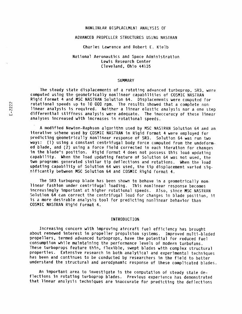
SUMMARY
The steady state displacements of a rotating advanced turboprop, SR3, were
computed using the geometrically nonlinear capabilities of COSMIC NASTRAN
Rigid Format 4 and MSC NASTRAN Solution 64. Displacements were computed for
rotational speeds up to lO 000 rpm. The results showed that a complete non-
linear analysis is required. Neither a linear elastic analysis nor a one step
differential stiffness analysis were adequate. The inaccuracy of these linearanalyses increased with increases in rotational speeds.
A modified Newton-Raphson algorithm used by MSC NASTRAN Solution 64 and an
Iteratlve scheme used by COSMIC NASTRAN in Rigid Format 4 were employed forpredicting geometrlcally nonlinear response of SR3. Solution 64 was run two
ways: (l) using a constant centrifugal body force computed from the undeform-
ed blade, and (2) using a force Field corrected in each iteration for changes
in the blade's position. Rigid Format 4 does not possess this load updating
capability. When the load updating feature of Solution 64 was not used, thetwo programs generated similar tip deflections and rotations. When the load
updating capability of Solution 64 was used, the tlp displacement varied slg-nlflcantly between MSC Solution 64 and COSMIC Rigid Format 4.
The SR3 turboprop blade has been shown to behave in a geometrically non-
linear fashion under centrifugal loading. This nonlinear response becomesincreasingly important at higher rotational speeds. Also, since MSC NASTRAN
Solution 64 can correct the centrifugal load for changes in blade position, It
is a more desirable analysis tool for predicting nonlinear behavior thanCOSMIC NASTRAN Rigid Format 4.
INTRODUCTION
Increasing concern with improving aircraft fuel efficiency has broughtabout renewed interest in propeller propulsion systems. Improved multl-bladed
propellers, termed advanced turboprops, have the potential for reduced fuel
consumption while maintaining the performance levels of modern turbofans.
These turboprops feature thin, flexible, swept blades with complex structural
properties. Extensive research in both analytical and experimental techniqueshas been and continues to be conducted by researchers In the field to better
understand the structural and aerodynamic response of these complicated blades.
An important area to investigate is the computation of steady state de-
flections in rotating turboprop blades. Previous experience has demonstrated
that linear analysis techniques are inaccurate for predicting the deflections
of these rotating blades. Because the blades are relatively flexible theyrespond to loading wlth relatively large deflections. Thls complicates thecalculation of the blade's stiffness since the stiffness and deflections aremutually dependent. The computation of this behavior requires a geometricallynonlinear analysis.
The analysis Is further complicated by the fact that the centrifugal loadsare also displacement dependent. Since centrifugal force Is proportional tothe radius from the rotational axls the magnitude and distribution of cen-trlfugal loads wlll change as the blade displaces. The research presented Inthis paper investigates thls effect.
The purpose of the research presented In thts paper ts to investigate theuse of NASTRAN, a well-known finite element program, for predicting steadystate deflections of advanced turboprops subject:to centrifugal loading. Thlscomputer program was selected due to Its' nonlinear analysis capability andavailability. Furthermore, It ts universally accepted and has been used suc-cessfully to analyze geometrically nonlinear structural problems In the past.Two versions of NASTRAN were employed, the first was MSC (Macneal-Schwendler Corporation) NASTRAN Solution 64; the second was COSMIC (ComputerSoftware Management and Information Center) NASTRAN Rigid Format 4. Both ofthese programs can be used for geometrically nonlinear analyses. It ts con-ventent to use COSMIC NASTRAN Rigid Format 4 because the stiffness matrixgenerated In thts program is tn a format compatible for input Into the sub-sequent aerodynamic flutter analysis. The turboprop blade was analyzed usingMSC NASTRAN Solution 64 In order that the results from rigid format 4 could becompared to an independent nonllnear analysis.
A representative advanced turboprop, named SR3, was used as the model forinvestigating the use of NASTRAN for computing deflections of advanced turbo-props. SR3 has most of the structurally related characteristics found Intypical advanced turboprop blades (fig. I).
BACKGROUND
At NASA Lewis Research Center COSMIC NASTRAN runs on a UNIVAC II00 com-
puter system which utilizes a 32 blt processor and uses double precision. MSC
NASTRAN Is run on a Cray l-S. Thls program uses single precision and a 64 blt
processor.
As previously mentioned, it Is desirable to use COSMIC NASTRAN for the
nonlinear analysis because the results from thls program can easily be used In
the aerodynamic flutter analysis. Since both the nonllnear analysis (Rigid
Format 4) and the aerodynamic flutter analysis (Rigid Format 9) are run on the
UNIVAC using COSMIC NASTRAN, It Is relatively simple to transfer results from
one program to the other. More specifically, It Is necessary that the stif-
fness matrix generated from the nonlinear analysis in Rigid Format 4 be trans-
ferred to Rigid Format 9 for use In the flutter analysis. If the flutter
analysis does not use a stiffness matrix that includes nonlinear effects, cor-
rect frequencies will not be computed and the results of the flutter analysiswlll be in error. The stiffness matrlx from MSC Solution 64 cannot be used

for the flutter analysis because there is presently no practical method for
transferring matrices between MSC and COSMIC NASTRAN. An effort is currentlybeing made to eliminate this problem.
From among all the MSC and COSMIC NASTRAN solution sequences available for
geometrically nonlinear response Solution 64 is thought to be the most
complete. In order to verify the accuracy of Rigid Format 4, the results fromthis program are compared to the results from MSC NASTRAN Solution 64.
MSC NASTRAN Solution 64 for Geometrically Nonlinear Analysis
MSC NASTRAN Solution 64 provides a straightforward means for performing
geometrically nonlinear analysis utilizing a modified Newton-Raphson algorithm(refs. l and 2). The algorithm used in this solution sequence is described in
the MSC NASTRAN application manual and will be repeated here for the reader's
convenience. To best understand the Newton-Raphson algorithm used by MSCNASTRAN, a simplified incremental scheme will first be described and then it
will be shown how this scheme may be expanded into the Newton-Raphsonalgorithm.
The objective of a nonlinear analysis is to simulate the correct displace-
ment versus load relationship. One means of accompllshlng this is to use anincremental algorithm in which the nonlinear response is divided into a series
of linear steps, each step representing an increase in load (fig. 2).Displacements are accumulated after each step and a new tangent stiffness is
calculated based on the structure's deformed position. By using this approachthe nonlinear response can be approximated by a series of linear segments.
The load increment determines how close the approximation will match the
actual response curve. The larger the load increment, the further the computed
response will be from the actual response. When large load steps are used,
the purely incremental algorithm will deviate considerably from the correct
structural behavior. As shown in figure 2, while the actual displacement for
applied load R is at Da, the computed displacement is only at D3.
This deviation results in equilibrium conditions not being satisfied at the
end of the load step. While the difference AR between externally applied
loads and internal element forces should equal zero, they are actually equalto a nonzero value.
The error produced by the incremental approach can be eliminated in the
limit by requiring that equilibrium conditions be satisfied at the end of each
load step. This approach is analogous to the conventional Newton-Raphson
algorithm. The MSC NASTRAN form of the Newton-Raphson approach requires that
equilibrium be satisfied (AR = O) by balancing the externally applied loads
and the internal forces at the end of each load step. This constraint pro-
hibits the computed response from deviating from the actual response. Thisalgorithm has the added advantage that, for typical structures where the Ioad-
displacement curve is relatively smooth, the entire load can be applied in thefirst step without effectlng the accuracy of the final results.
The MSC NASTRAN form of the Newton-Raphson algorithm is based on an Iter-
atlve solution of the equation of equilibrium. In matrix notation, thisequation takes the form:
3

[K i] {aOi+ I} : {AR i} (I)
Where the load imbalance {AR i} = {R a} - Z[kl] {dl}. [Ki] and [kl]are the global and element stlffnesses respectively, {R a} is the appliedload, {d i} are the element displacements, and {aDi+ I} is the incrementin the global displacement at the end of the iteration. The global stiffnessmatrix [Ki] includes both the elastic and differential stiffness matrices.
The Newton-Raphson algorithm is shown graphically in figure 3. For the
initial iteration, the structure begins in its undeformed position with the
internal forces set to zero (z[kl] {di} = {0}. This reduces the right side
of equation (1) to the applied load vector {Ra}.
By using the load {Ra} and the tangent stiffness [Ko] at the origin, the
displacement {AD l} is computed. After applying {ADl} to the undeformedblade, the position of the displaced blade is established. Using this deformed
shape, the internal forces (z[kl] {dl}) are generated along with a new
tangent stiffness. The next iteration is initiated by computing a new set
of displacements using the imbalance ({Ra} - _[kl] {dl}) as the applied
load and the new tangent stiffness as the stiffness. This procedure is re-
peated until the load imbalance is reduced to within the desired tolerance.
Reducing the tolerance produces more accurate results but requires additionaliterations.
It is not mandatory for the load vector {Ra} to be equal to the
total external load in every iteration. Instead, {Ra} can be only a
fraction of the total external load in early iterations and then can be in-
cremented to the full load in the final iterations. In the example shown in
figure 3, {Ra} is taken as the full externally applied load in every
iteration. If the structure is highly nonlinear and the total external loadis applied in the initial iterations the structure may move to an unstable
condition. The advantage of using load increments is that the path to
instability can be monitored.
In the modified Newton-Raphson approach the elastic stiffness matrix is
not updated in each iteration. Instead, the original stiffness matrix derived
from the undeformed geometry is used for every iteration. Using this original
stiffness does not affect the final results because the final displacement is
independent of the path used! (The element stlffnesses which are used to
compute the load imbalance on the right side of eq. (1) are updated in each
iteration.) By referring to figure 3, one can visualize the affect of using
the same stiffness in every iteration. If [Ko] is used as the stiffness in
every iteration, the incremental displacements wlll be different from the
displacements shown in figure 3 (altering the path), but the final converged
displacement will still be equal to Da.
The advantage of using an unaltered stiffness matrix is that the cost of
forming and decomposing a new elastic stiffness matrix for each cycle is
eliminated. The disadvantage is that the solution will require more iter-
ations to converge. Although the elastic stiffness need not be updated with
MSC NASTRAN, the user does have the option of computing a new differential
stiffness matrix in any iteration. It is useful to be able to update the dif-
ferential stlffnesses matrix since it is a function of element stresses and
can change considerably with load increments.
4

MSC NASTRAN Solution 64 uses "subcases" to control the execution of the
nonlinear analysis. Specifically, the number of subcases specified in the
NASTRAN input data deck determines the number of iterations that will be per-formed. The user must specify at least two subcases. In the first subcase a
linear elastic analysis is used to compute an initial deflected shape. This
displaced shape is then used in the second subcase to compute the differential
stiffness matrix along with a new set of displacements. Subsequent subcases
are used for iterating on the equilibrium equation (eq. l).
Solution 64 has two important features that increase the flexibility of
the nonlinear analysis. First, Solution 64 has the_abillty to recompute the
external loads before each iteration. This is particularly advantageous for
centrifugal !oads since they are dependent on the radius of the blade's mass
from the rotational axis and will, therefore, change in each iteration as the
blade deflects. The second asset of Solution 64 is its ability to apply a
fraction of the full external load in earlier subcases. This advantage has
previously been discussed. Neither of these cap@billties are available inCOSMIC NASTRAN Rigid Format 4.
COSMIC NASTRAN Rigid Format 4 for Differential Stiffness
Rigid Format 4 of COSMIC NASTRAN is designed to solve geometrically non-linear problems (ref. 3). Thls rlgld format uses an Iteratlve solution
sequence based on an extension of the one step differential algorithm. Thegoverning equation for this rigid format is:
{Ra} (2)
Where [K] is the global elastic stiffness, [Kd (Di) ] is the differential
stiffness computed for the displaced blade at {Di}, {Ra} is the
applied load, and {Di+ l} is the displacement computed at the end of the
iteration. In this equation the differential stiffness matrix [Kd] is up-dated in each iteration whereas the elastic stiffness [K] remains constant.
Equation (2) is not guaranteed to converge to the correct displacement because
this equation, unlike equation (]), contains no check to insure a small loadimbalance between internal element forces andexternal body forces. Thus, for
highly nonlinear structures, equation (2) may not converge.
Rigid Format 4 requires two subcases. The first subcase is used for per-forming linear elastic analyses without incorporating differential stiffness.
The resulting element stresses from the first subcase are used in the second
subcase to compute the differential stiffness matrix. Equation (2) is then
repeated until the weighted difference between the differential stiffness in
subsequent iterations is within the desired tolerance or until the maximum
desired number of iterations has been completed. Both the tolerance and
number of iterations can be controlled by the user. The linear elastic and
initial differential analyses performed by Rigid Format 4 are comparable tothe first two subcases of MSC NASTRAN Solution 64.
The major limitation of using Rigid Format 4 for computing deflections of
rotating structures is the inability to compensate for the change in the
centrifugal body force as the blade displaces. This limitation can introduceconsiderable error.

RESULTS
A comparison of results between MSC NASTRAN Solution 64 and COSMIC NASTRAN
Rigid Format 4 was made using the advanced turboprop model SR-3. This turbo-
prop blade is a small scale titanium model measuring 12-1/4 in. from the
rotational axls to the blade tip. The blade thickness decreases from over one
in. at the root to 0.016 in. at the tip. As shown in figure l, the blade is
both highly swept and twisted. This geometry is intended to optimize aero-
dynamic performance and minimize noise while maintaining structural integri-
ty. The finite element model consists of 346 triangular plate elements and
206 grid points. The "CTRIA2" and "CTRIA3" elements were used for the COSMIC
and MSC runs, respectively. The plate element formulations include both
membrane and bending action. The base of the root of the blade is modeled as
fully constrained.
MSC NASTRAN Solution 64 was used to compute steady state displacements of
SR-3 at 3500, 7000, 8600, and lO 000 rpm. Two sets of displacement data were
generated. The first set was generated using a constant centrifugal body
force computed from the original, undeformed blade. The second set used a
body force updated in each iteration based on the position of the deformed
blade. Seven subcases (5 iterations) were used for Solution 64. Convergence
was evaluated by comparing the difference in displacements between the sixth
and seventh subcases which were on the order of only one tenth of one percent.
The five iterations produced a ratio of unbalanced forces at unconstrainednodes to forces at the constrained root of lO-4. This small ratio indicates
that the load imbalance at the unconstrained nodes is relatively small and
that equation (1) has adequately converged.
Steady state displacements were computed using COSMIC NASTRAN Rigid Format4 at the same rotational speeds as MSC Solution 64. Only two iterations are
required to produce converged displacements at 3500 rpm. Additional iter-
ations changed the final displacements by only I/2 percent. The number of
iterations was increased to three by decreasing the default tolerance from
lO-5 to lO -6 (PARAM, EPSIO, l.E-6). At lO 000 rpm seven iterations were
required for the same order of accuracy.
Similar finite element formulations are used for both COSMIC NASTRAN and
MSC NASTRAN. As expected, the two programs computed similar, though not
identical, displacements in the linear elastic subcase. The small discrepancy
in the displacements is probably the result of either the minor difference in
element formulations or the difference in criteria used by the two programsfor testing small values of stiffness in the global stiffness matrix. Since
the formulation for triangular plate elements does not include In-plane
rotational stiffness, the assembled global stiffness matrix may contain very
small or zero entries. These small values are usually removed by constraining
appropriate rotational degrees of freedom. The default minimum value used by
COSMIC NASTRAN is larger than the value used by MSC NASTRAN. Thus more con-
straints are present in the COSMIC runs. These additional constraints add
stiffness to the blade and typically lower the Rigid Format 4 elastic dis-
placements. However, the displacements in the subsequent nonlinear analysis
do not appear to be affected by the additional constraints.
Tip deflection (defined as total deflection of mldchord at blade tip) as afunction of rotational speed is shown in flgure 4. The general trend is for

deflections to increase up to around 7000 rpm and then level off. All threeanalyses follow thls trend. COSMIC Rigid Format 4 and MSC Solution 64produced similar results when centrifugal loads were not updated wlth changesIn blade position. The difference In tip deflections between these twosolutions wlth no load update decreased from 14 percent at 3500 rpm to only 5percent at I0 000 rpm. There is a constant 0.01 Inch difference In displace-ment between the two solutions above 3500 rpm. When the load updatingcapability of Solution 64 was utilized, the deflections were conslderably dlf-ferent. The deflection curve generated using the load updating algorithmshows larger deflections than the other two curves (32 percent larger atI0 000 rpm). Thls was expected because the centrifugal force actually In-creases as the blade straightens out and the radius of the blade's mass fromthe rotational axls increases. It is evident that at high rotational speeds aload updating algorithm must be used to account for the large changes In bladeposltlon.
Figure 5 shows blade tlp rotation as a function of rotational speed, llp
rotation Is defined as blade tip chord twist about the pitch axis In a plane
normal to the pitch axis. The pitch axis Is shown In figure I. The general
trend in thls figure Is for the blade to untwist as rotational speed increas-
es. As wlth tlp deflections, Solution 64 with load updating produced the
largest rotations. The differences between the load updating and constant
load solutions were not as notable for tip rotations as they were for tlp mid
chprd deflections. The variation In tip rotations between Rigid Format 4 and
Solution 64 wlth load updating was 19 percent at lO 000 rpm.
Figure 6 shows a comparison between the three levels of analysls used In
MSC NASTRAN Solution 64. As expected, the linear elastic analysis (subcase ])
over predicted the tlp deflection. Thls Is due to the stlffenlng effect from
the centrifugal force field which was not included in the linear analysis.
The relationship between deflection and rotational speed Is parabolic since
centrifugal force Is proportional to the square of rotational speed. Thedeflection computed in the linear analysis is in contradiction to the trend
predicted by the nonlinear analysis shown in the same figure. The nonlinear
analysis shows the tlp deflection leveling off. The displacements from sub-
case l are considerably greater than those computed in subcase 2, which
includes centrifugal stiffening effects. While the tlp displacement was over
0.80 in. at lO 000 for the linear solution, it was only 0.21 In. for the llne-
ar elastic plus differential analysis. The difference in deflections between
the linear and nonlinear solutions Is shown by comparing subcases l and 2 to
subcase 7. The difference in tlp deflection at lO OOO rpm, between subcase 7
and subcase l and 2 Is 75 and 33 percent, respectively. Thls large variationbetween the nonlinear and linear subcases is a good indicator of the blade's
strong nonlinear behavior.
CONCLUDING REMARKS
Because of Its ability to update the displacement dependent centrifugalforce during the solution process, MSC NASTRAN Solution 64 was shown to be
superior to COSMIC NASTRAN Rigid Format 4 for the geometrically nonlinear
analysis of advanced propeller blades. However, it cannot be concluded that

MSCNASTRANSolution 64 accurately predicts the steady displacement of advancedturboprop blades until additional analytical and experimental studies are com-
pleted.
REFERENCES
I. Joseph, Jerrard A., ed.: MSC/NASTRAN Application Manual. MacNeal-
Schwendler, 1981.
2. Cook, R. D.: Concepts and Applications of Finite Element Analysis.
Wiley a Sons, 1974, pp. 259-2?0.
3. NASTRAN Theoretical Manual. NASA SP-221(06), 1977.
J.

/-Tip mldchord node/
/
\
Pitchax '*- Constrainednodes
i=-
Rotationalaxis
(a) SR3turbopropfinite elementmodel.
Figure1.
(b) SR3turbopropfinite elementmodel
Figure L - Concluded.
T---R
AR1
_/ : _Purely incremental
XII i cur"II I I _
D1 D2 D3 Da
P Displacement '
FigureZ - Incrementalalgorithm for nonlinear analysis.

_New_-Raphs(_ ,-Adual response
\1-- a -
&R- Ra-R! _ [ ][[_:oF_._#__mII/__D a LAR<TOL--R l
D1 D2 D3 O4
Displacement
Figure 3. - Newton-Raphsonsolutionfor nonlinear analysis.
.20
,J .10
.-r¢J
-- t_ MSC-no loadupdateo COSMIC
l i5000 !0000
Bladerolationalspeed,rpm
Figure 4. - SR3tip displacementversusrotational speed.
m !
.80
I_ MSC--noloadupdate ,_
_ 0 COSMIC "" _ .60
_ .40
E
eL .20
5OOO 10 _
Bladerotationalspeed,rpm
FigUre5. - SR3tip rotationversus rotational speed. 0
/o/_ _lnear elastic
/ ;Nonlinear (subcase7)
5000 10 OOO
Bladerotationalspeed,r_
Fic_re 6. - Comparisonof linear elastic, differenl_l, and nonlinearanalysesusedby MSC solution64.

1. Report No.
NASA TM-83737
2. Government Accession No.
4. Title and Subtitle
Nonlinear Displacement Analysis of AdvancedPropeller Structures Using NASTRAN
7. Author(s)
Charles Lawrence and Robert E. Kielb
9. Performing Organization Name and Address
National Aeronautics and Space AdministrationLewis Research CenterCleveland, Ohio 44135
12. Sponsoring Agency Name and Address
National Aeronautics and Space AdministrationWashington, D.C. 20546
3. Reclpient's Catalog No.
5. Report Date
August 1984
6. Performing Organization Code
535-03-12
8. Performing Organization Report No.
E-2222
10. Work Unit No.
11. Contract or Grant No.
13. Type of Report and Period Covered
Technical Memorandum
14. Sponsoring Agency Code
15. Supplementary Notes
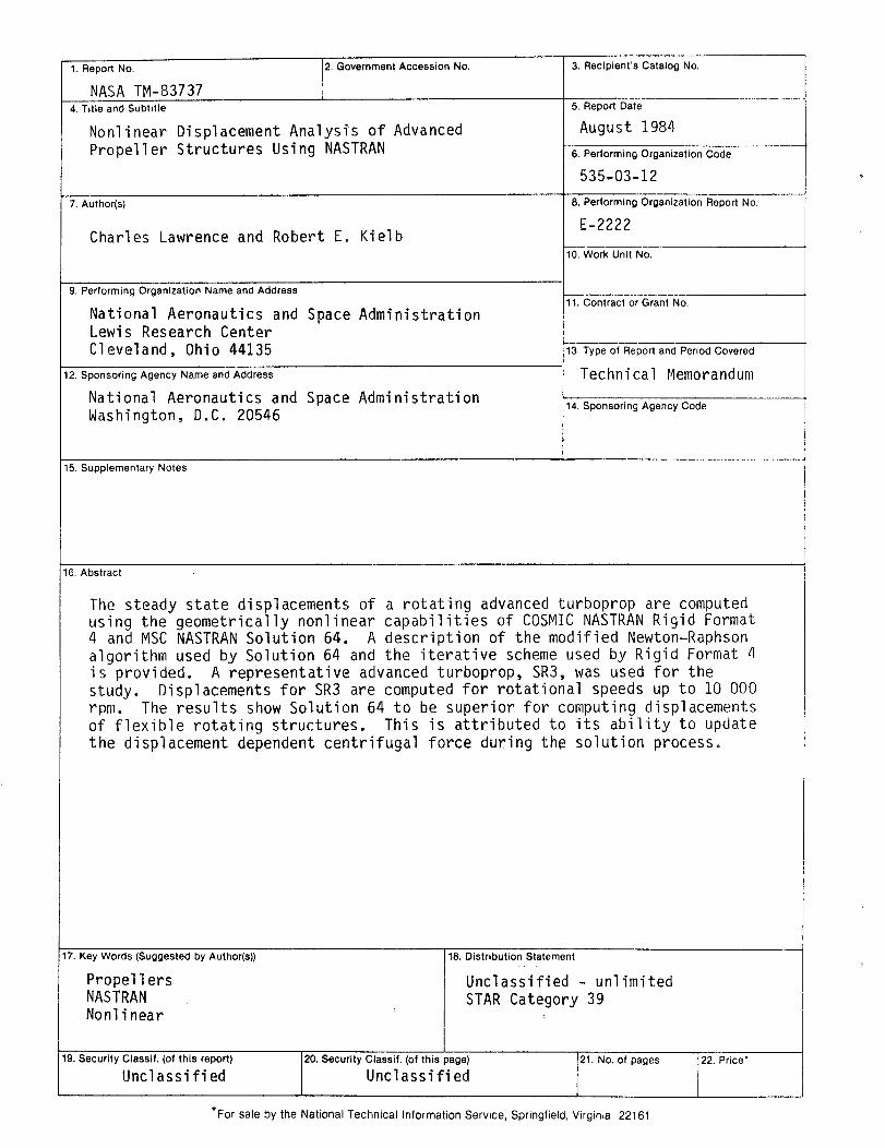
16. Abstract
The steady state displacements of a rotating advanced turboprop are computedusing the geometrically nonlinear capabilities of COSMIC NASTRAN Rigid Format4 and MSC NASTRAN Solution 64. A description of the modified Newton-Raphsonalgorithm used by Solution 64 and the iterative scheme used by Rigid Format 4is provided. A representative advanced turboprop, SR3, was used for thestudy. Displacements for SR3 are computed for rotational speeds up to 10 000rpm. The results show Solution 64 to be superior for computing displacementsof flexible rotating structures. This is attributed to its ability to updatethe displacement dependent centrifugal force during the solution process.
17. Key Words (Suggested by Author(s))
PropellersNASTRANNonlinear
18. Distribution Statement
Unclassified - unlimitedSTAR Category 39
19. Security Classif. (of this report) 20. Security Classif. (of this page) 21. No. of pages
Unclassified Unclassified
*For sale by the National Technical Information Service, Springfield, Virginia 22161
22. Price"