nonlinear optics continued- - kth
TRANSCRIPT

1
Nonlinear optics continued-waveguides and parametric devices
Fredrik Laurell
Department of Applied PhysicsKTH – Royal Institute of Technology, Stockholm, Sweden
2
Outline
• Optical waveguides – integrated optics
• Nonlinear integrated optics
• Introduction to parametric devices
• Optical parametric oscillators• Singly resonant OPOs vs. doubly resonant OPOs• Practical examples
• Summary
3
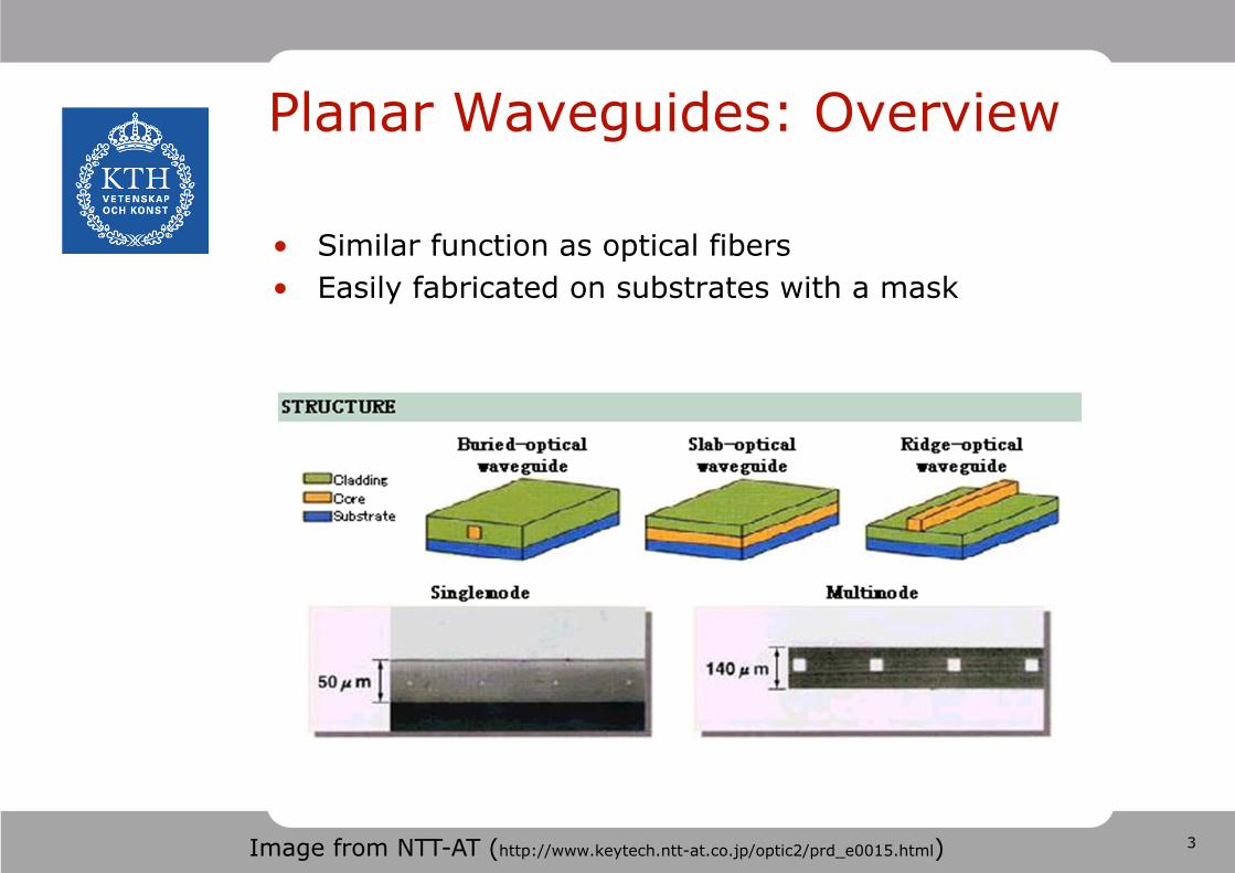
Planar Waveguides: Overview
• Similar function as optical fibers• Easily fabricated on substrates with a mask
Image from NTT-AT (http://www.keytech.ntt-at.co.jp/optic2/prd_e0015.html)
4
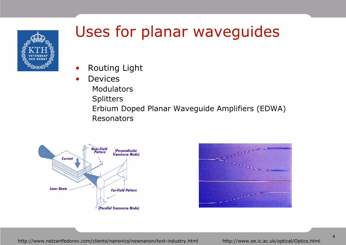
Uses for planar waveguides
• Routing Light• Devices
ModulatorsSplittersErbium Doped Planar Waveguide Amplifiers (EDWA) Resonators
http://www.ee.ic.ac.uk/optical/Optics.htmlhttp://www.netzartfedorov.com/clients/nanonics/newnanon/text-industry.html
5
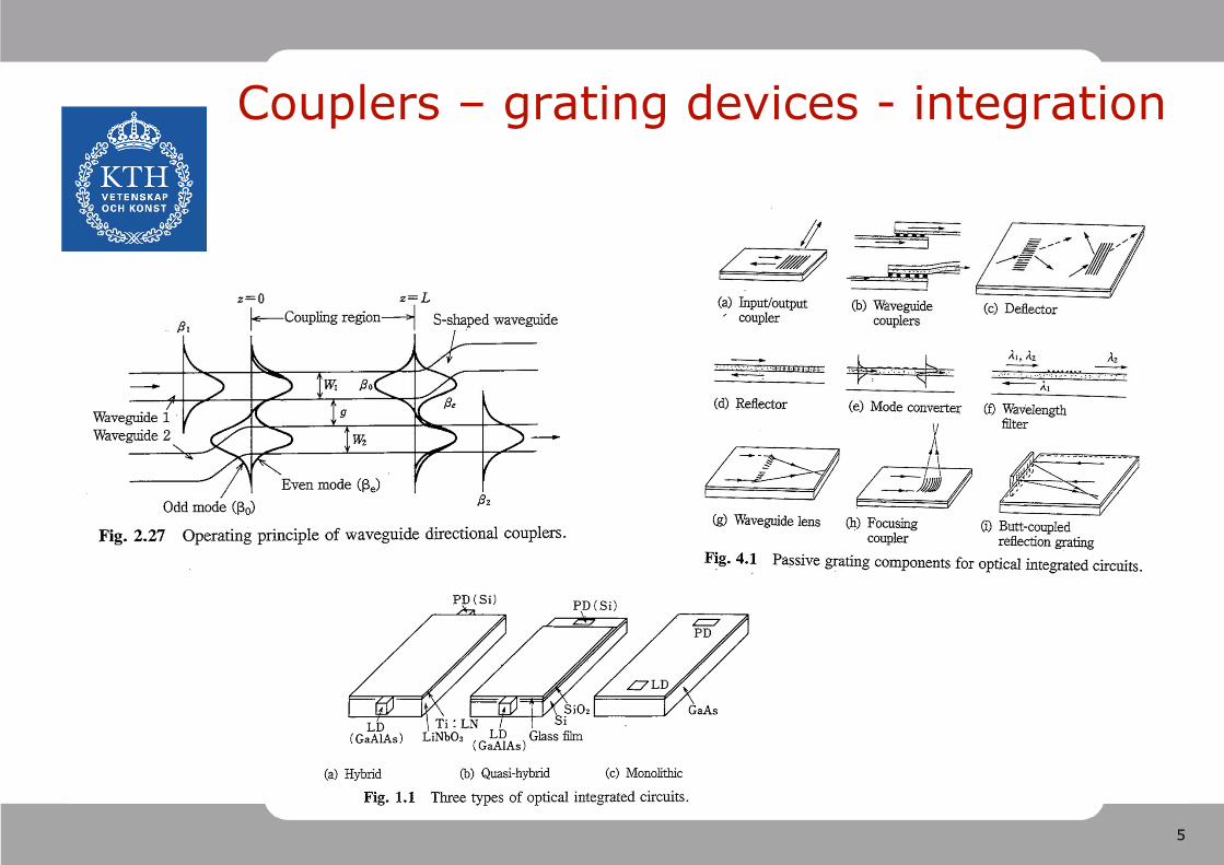
Couplers – grating devices - integration

6
Maxwells Equations in Slab Waveguide
• Maxwell’s Equations
• Simplifications
7
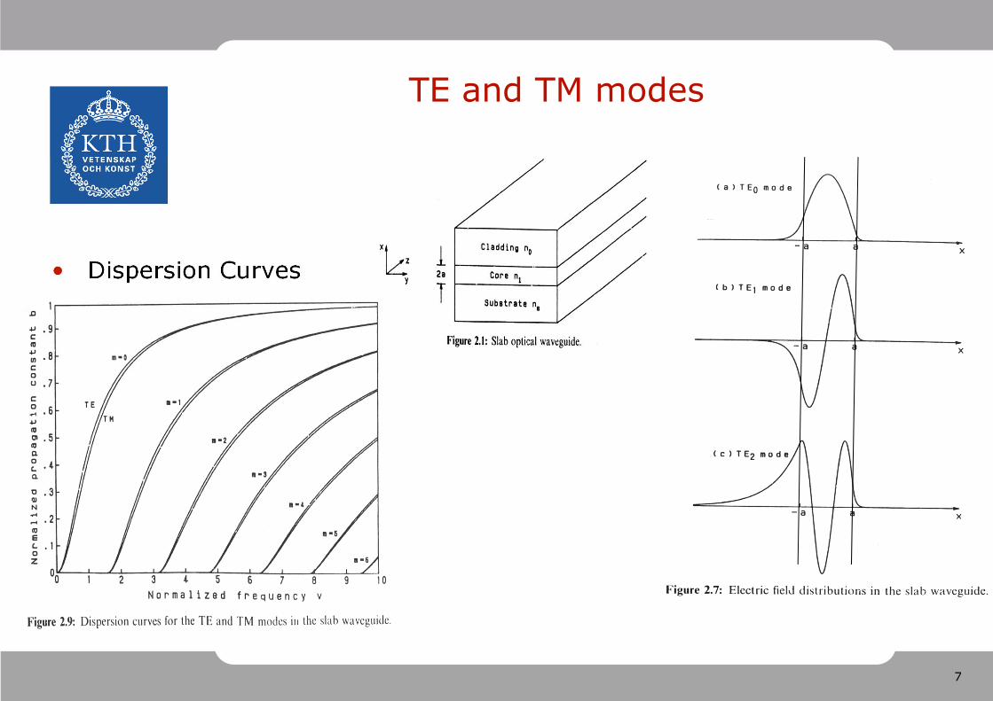
TE and TM modes
• Dispersion Curves
8
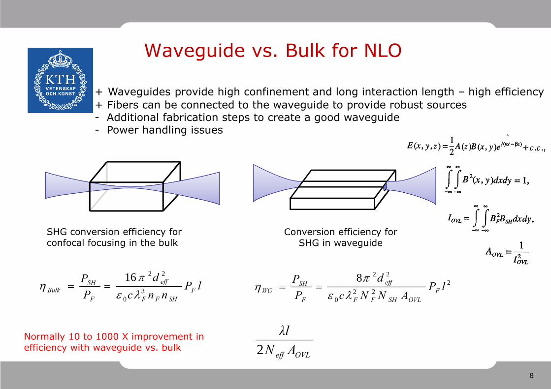
Waveguide vs. Bulk for NLO
+ Waveguides provide high confinement and long interaction length – high efficiency + Fibers can be connected to the waveguide to provide robust sources- Additional fabrication steps to create a good waveguide- Power handling issues
SHG conversion efficiency for confocal focusing in the bulk
Conversion efficiency for SHG in waveguide
Normally 10 to 1000 X improvement in efficiency with waveguide vs. bulk
lPnncd
PP
FSHFF
eff
F
SHBulk 3
0
2216
222
0
228lP
ANNcd
PP
FOVLSHFF
eff
F
SHWG
OVLeff ANλl
2
9
Why optical parametric devices?
• Very wide continuous tuning from a single device, via tuning of the phase-match condition
• High efficiency
• No heat input to the nonlinear medium
• No analogue of spatial-hole-burning as in a laser, hence simplified single-frequency operation
• Very high gain capability
• Very large bandwidth capability
10
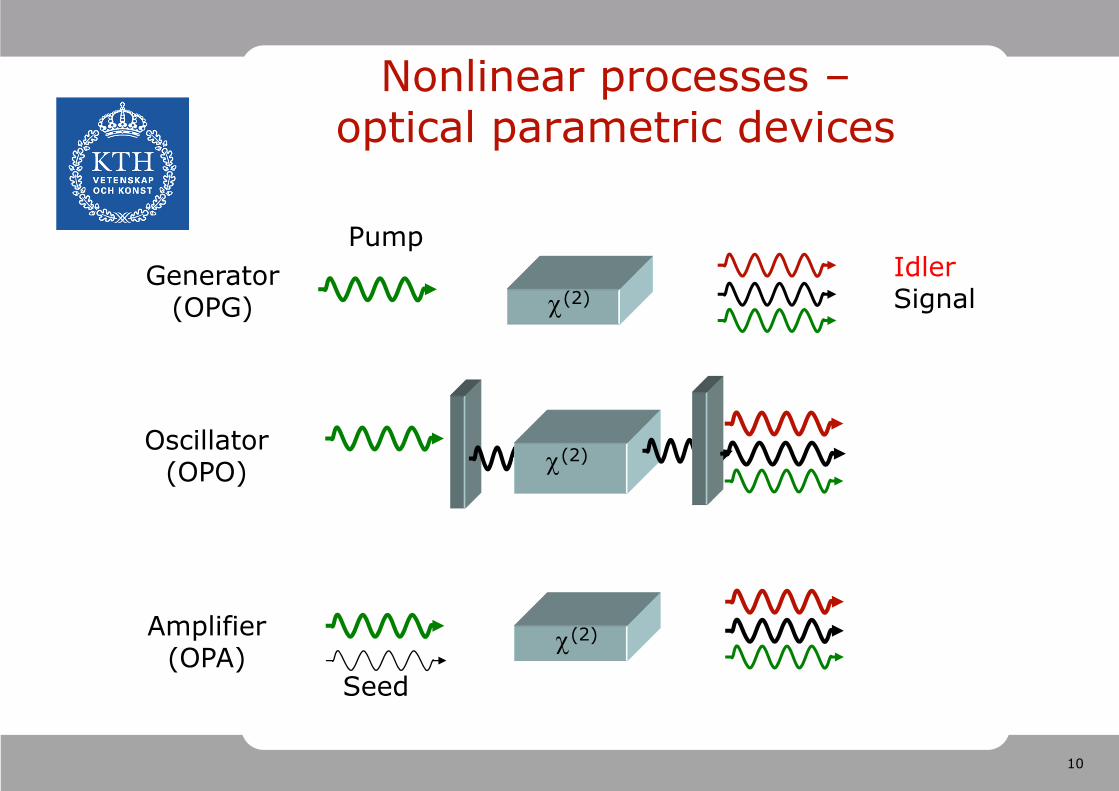
Oscillator(OPO) (2)
Nonlinear processes –optical parametric devices
PumpIdlerSignal(2)
Generator(OPG)
Seed
Amplifier(OPA)
(2)
11
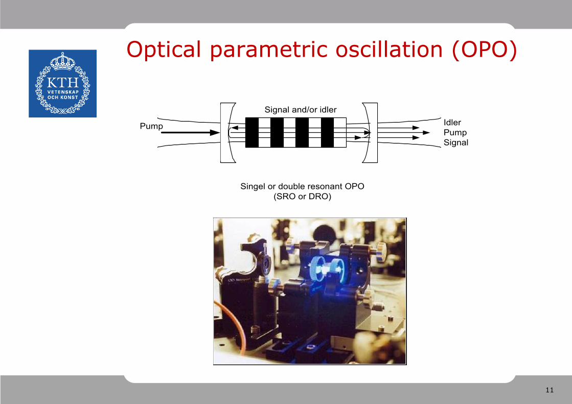
Optical parametric oscillation (OPO)
IdlerPumpSignal
Singel or double resonant OPO(SRO or DRO)
Pump
Signal and/or idler
12
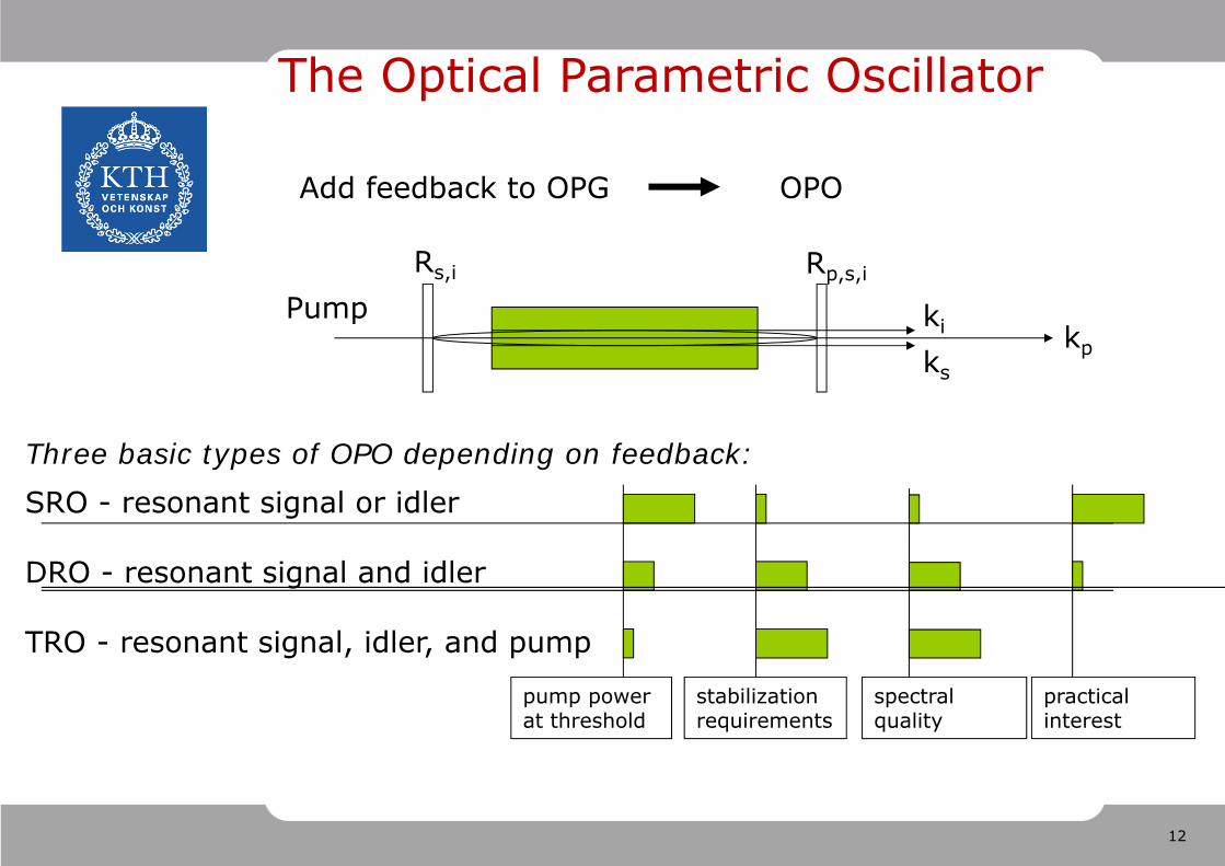
The Optical Parametric Oscillator
Pumpkpks
ki
Rp,s,iRs,i
Add feedback to OPG OPO
Three basic types of OPO depending on feedback:SRO - resonant signal or idler
DRO - resonant signal and idler
TRO - resonant signal, idler, and pump
pump power at threshold
stabilization requirements
practical interest
spectral quality

13
Manley-Rowe relationsIntegrals of the coupled equations
n3|E3(z)|2/ω3 + n2|E2(z)|2/ω2 = const
n3|E3(z)|2/ω3 + n1|E1(z)|2/ω1 = const
n2|E2(z)|2/ω2 – n1|E1(z)|2/ω1 = const
Number of pump photons annihilated in the NL medium equals the number of signal photons created, which also equals the number of idler photons created
Imply
n3|E3(z)|2 + n2|E2(z)|2 + n1|E1(z)|2 = consti.e. conservation of power flow in propagation direction
14
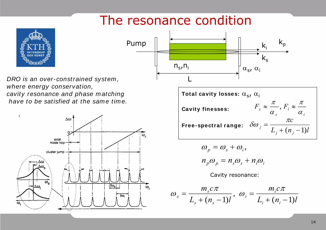
The resonance condition
DRO is an over-constrained system, where energy conservation, cavity resonance and phase matchinghave to be satisfied at the same time.
kpPump
ks
ki
s, ins,ni
L
Total cavity losses: s, i
Cavity finesses:
Free-spectral range:
ii
ss FF
,
iisspp
isp
nnn
,
Cavity resonance:
lnLcm
lnLcm
ii
ii
ss
ss )1(
,)1(
lnLc
jjj )1(
15
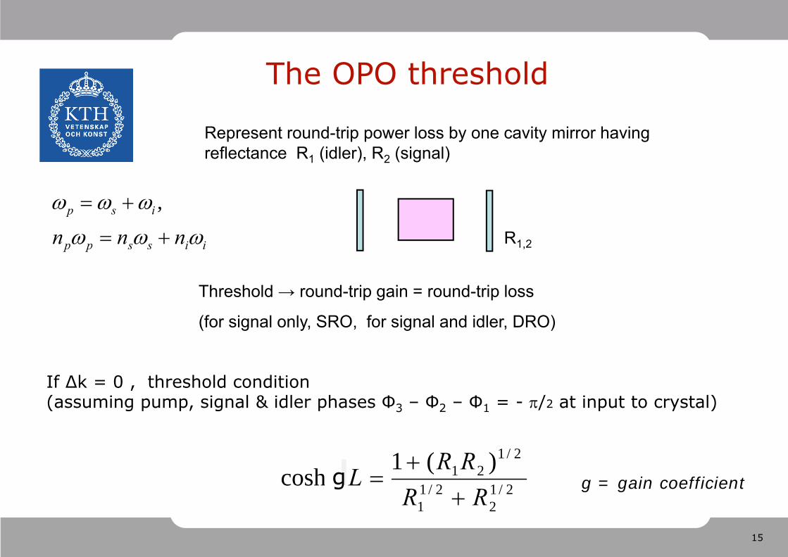
The OPO threshold
If ∆k = 0 , threshold condition (assuming pump, signal & idler phases Φ3 – Φ2 – Φ1 = - /2 at input to crystal)
2/12
2/11
2/121 )(1coshRRRRL
Represent round-trip power loss by one cavity mirror having reflectance R1 (idler), R2 (signal)
Threshold → round-trip gain = round-trip loss
(for signal only, SRO, for signal and idler, DRO)
R1,2iisspp
isp
nnn
,
g g = gain coefficient
16
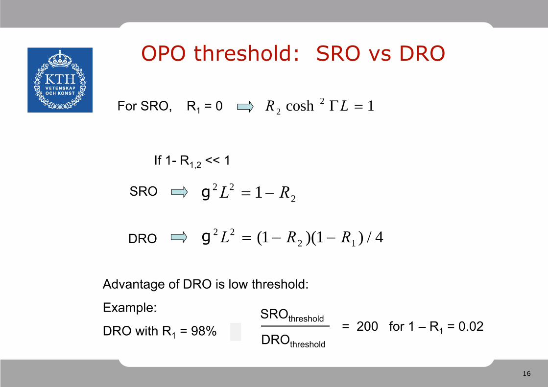
OPO threshold: SRO vs DRO
1cosh 22 LR
222 1 RL
4/)1)(1( 1222 RRL
For SRO, R1 = 0
SRO
DRO
Advantage of DRO is low threshold:
Example:
DRO with R1 = 98%
If 1- R1,2 << 1
SROthreshold
DROthreshold
= 200 for 1 – R1 = 0.02
g
g
17
Stability: comparison of SRO and DRO
SRO: No idler input. Gain does not depend on pump/signal relative phase.Signal frequency free to choose a cavity resonance;Idler free to take up appropriate frequency and phase. Signal frequency stability depends on cavity stability and pump frequency stability.
DRO: Cavity resonance for both signal & idler generally not achieved; OverconstrainedSignal/idler pair seeks compromise between cavity resonance and phase-mismatch;large frequency fluctuations
18
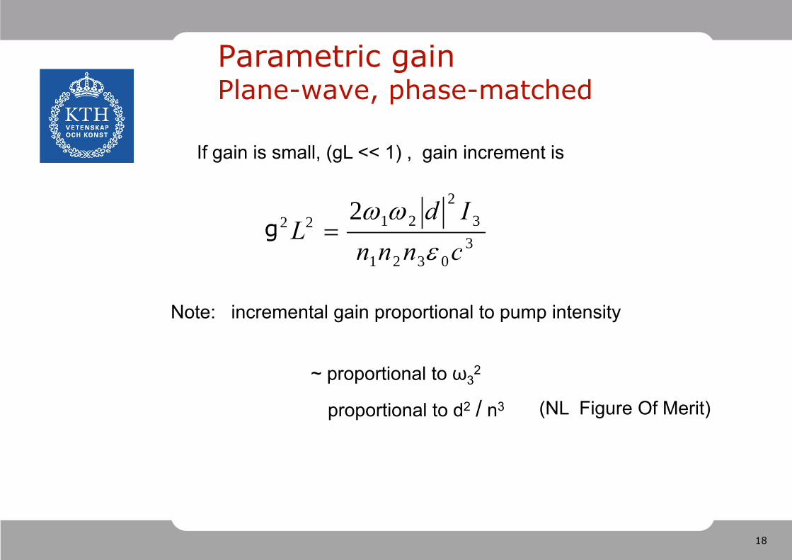
Parametric gainPlane-wave, phase-matched
If gain is small, (gL << 1) , gain increment is
Note: incremental gain proportional to pump intensity
~ proportional to ω32
30321
32
2122 2cnnnId
L
proportional to d2 / n3 (NL Figure Of Merit)
g
19
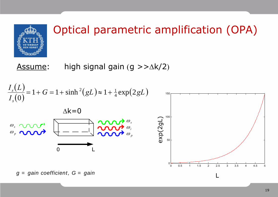
Optical parametric amplification (OPA)
Assume: high signal gain g >>k/2
k=0
gLgLG
ILI
s
s 2exp1sinh110 4
12
0 0.5 1 1.5 2 2.5 3 3.5 4 4.5 50
50
100
150
L
exp(
2gL)
p
i
s
p
0 L
s
g = gain coefficient, G = gain
20
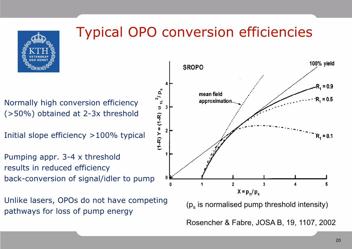
Typical OPO conversion efficiencies
Normally high conversion efficiency (>50%) obtained at 2-3x threshold
Initial slope efficiency >100% typical
Pumping appr. 3-4 x thresholdresults in reduced efficiency back-conversion of signal/idler to pump
Unlike lasers, OPOs do not have competingpathways for loss of pump energy
(ps is normalised pump threshold intensity)
Rosencher & Fabre, JOSA B, 19, 1107, 2002

21
Quasi-phase matching for OPOs
+ Noncritical interaction+ Longer interaction length+ Engineerable spectral output+ Accessing the highest (2) over the
entire transparency region− Additional processing step (= cost)− deff =2/d33
6 9 12 15 18 21 24 27 30 33 36 39 420,51,01,52,02,53,03,54,04,55,05,5
pump
= 1064 nm
pump
= 800 nm
pump
= 532 nm
Sig
nal/
idle
r [
m]
Grating period [m]
22
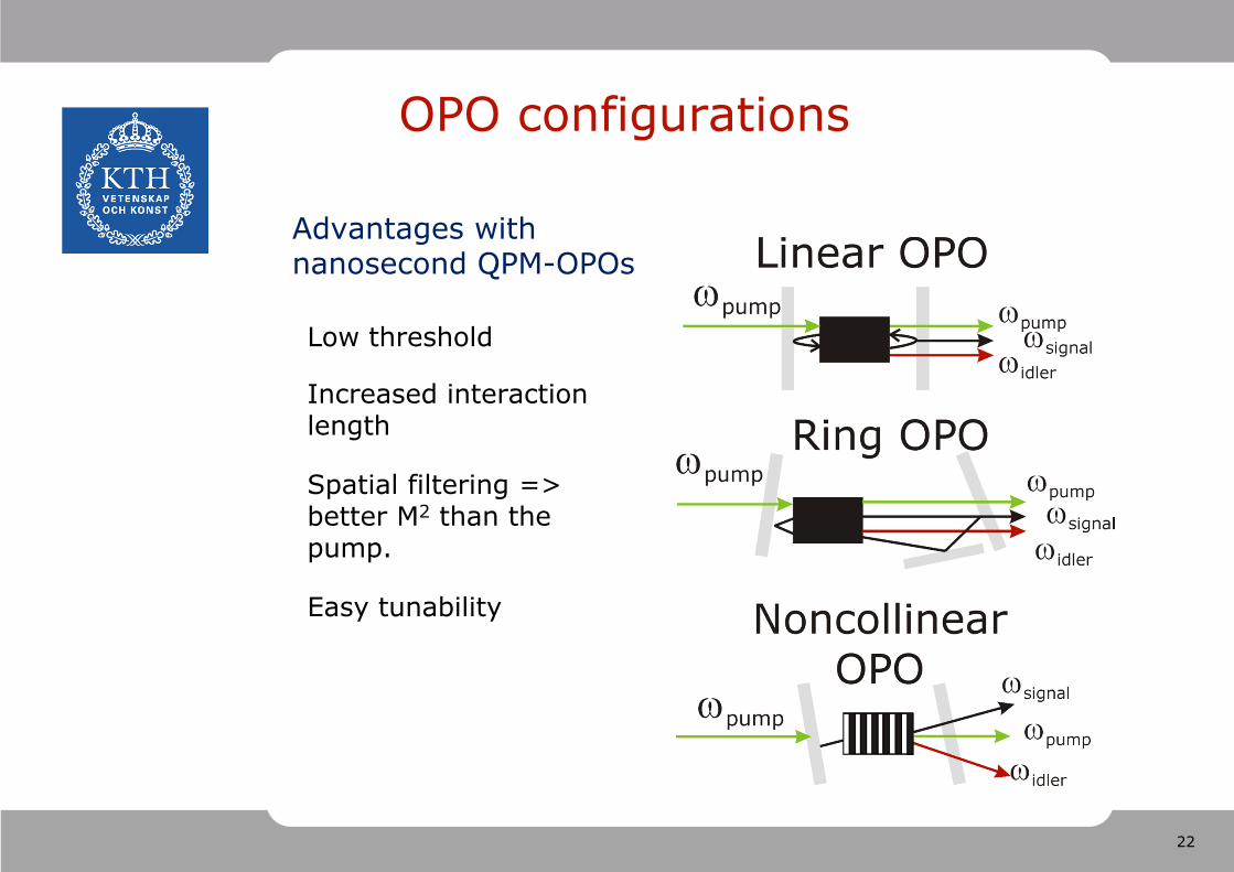
OPO configurations
Advantages with nanosecond QPM-OPOs
Low threshold
Increased interaction length
Spatial filtering => better M2 than the pump.
Easy tunability
23
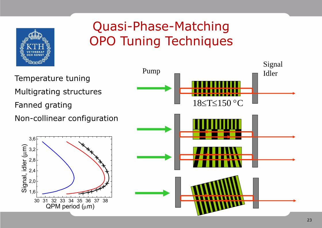
Quasi-Phase-MatchingOPO Tuning Techniques
Temperature tuning
Multigrating structures
Fanned grating
Non-collinear configuration
18T150 C
PumpSignal Idler
30 31 32 33 34 35 36 37 38
1,6
2,0
2,4
2,8
3,2
3,6
S
igna
l, id
ler (m
)
QPM period (m)
24
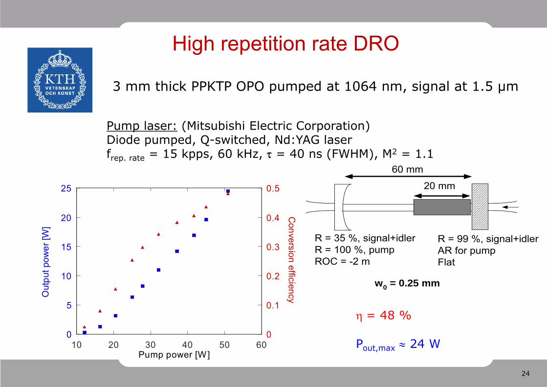
Pump laser: (Mitsubishi Electric Corporation)Diode pumped, Q-switched, Nd:YAG laserfrep. rate = 15 kpps, 60 kHz, = 40 ns (FWHM), M2 = 1.1
60 mm
20 mm
w0 = 0.25 mm
R = 35 %, signal+idlerR = 100 %, pumpROC = -2 m
R = 99 %, signal+idlerAR for pumpFlat
0
5
10
15
20
25
0
0.1
0.2
0.3
0.4
0.5
10 20 30 40 50 60
Out
put p
ower
[W]
Conversion efficiency
Pump power [W]
High repetition rate DRO
= 48 %
Pout,max 24 W
3 mm thick PPKTP OPO pumped at 1064 nm, signal at 1.5 µm
25
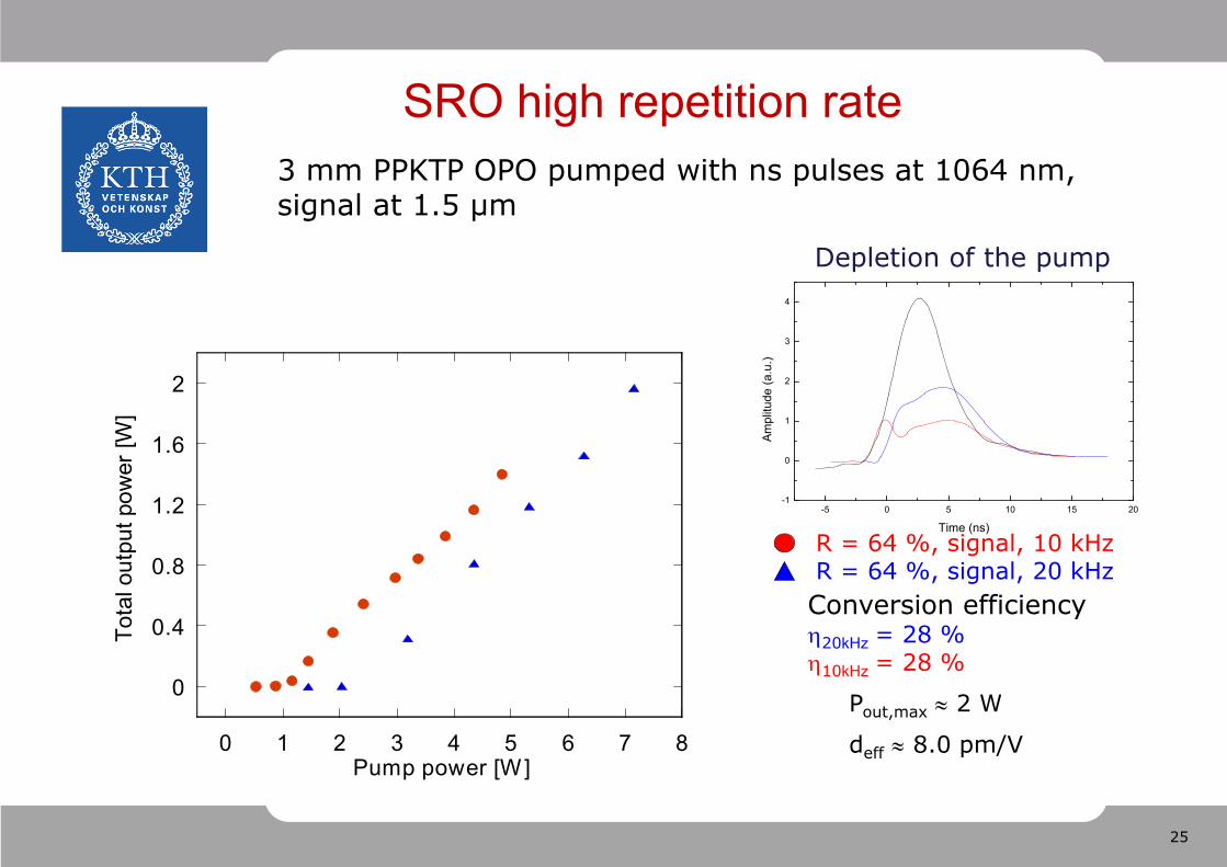
R = 64 %, signal, 10 kHzR = 64 %, signal, 20 kHzConversion efficiency20kHz = 28 %10kHz = 28 %
0
0.4
0.8
1.2
1.6
2
0 1 2 3 4 5 6 7 8
Tota
l out
put p
ower
[W]
Pump power [W]
Pout,max 2 W
deff 8.0 pm/V
SRO high repetition rate 3 mm PPKTP OPO pumped with ns pulses at 1064 nm,signal at 1.5 µm
-5 0 5 10 15 20-1
0
1
2
3
4
Ampl
itude
(a.u
.)
Time (ns)
Depletion of the pump
26
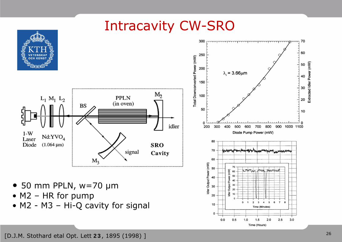
Intracavity CW-SRO
• 50 mm PPLN, w=70 µm• M2 – HR for pump• M2 - M3 – Hi-Q cavity for signal
[D.J.M. Stothard etal Opt. Lett 23, 1895 (1998) ]
27
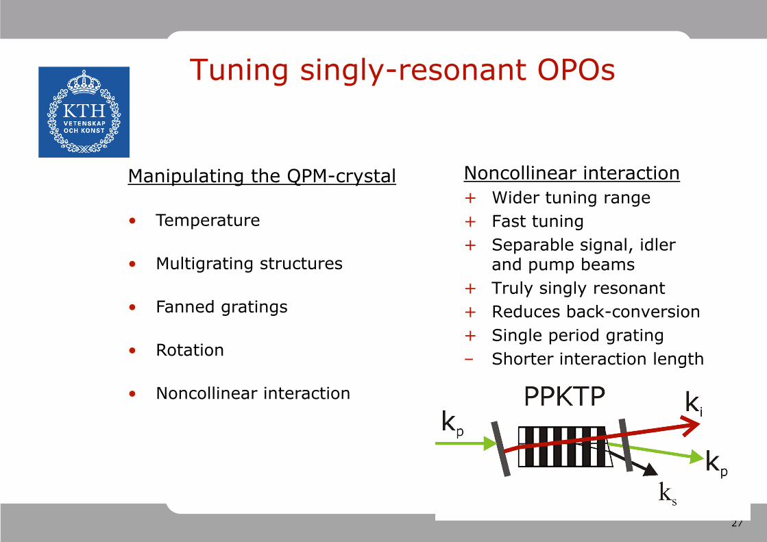
Tuning singly-resonant OPOs
Noncollinear interaction+ Wider tuning range+ Fast tuning+ Separable signal, idler
and pump beams+ Truly singly resonant+ Reduces back-conversion+ Single period grating– Shorter interaction length
Manipulating the QPM-crystal
• Temperature
• Multigrating structures
• Fanned gratings
• Rotation
• Noncollinear interaction

28
0 5 10 15 20 251500
2000
2500
3000
3500
Sign
al a
nd id
ler w
avel
engt
hs
s,i (
nm)
Rotation angle (°)
The pump laserNd:YAG, 6 ns, 10 Hz, M2 = 1.1
The PPKTP sample 2.1 mm diameter, = 35.0 mpoled area 10 by 10 mm2, thickness 0.5 mm,
= 17.3%, at = 26°. Etot = 74 JEpump = 430 J
Widely tunable OPO with circular PPKTP
29
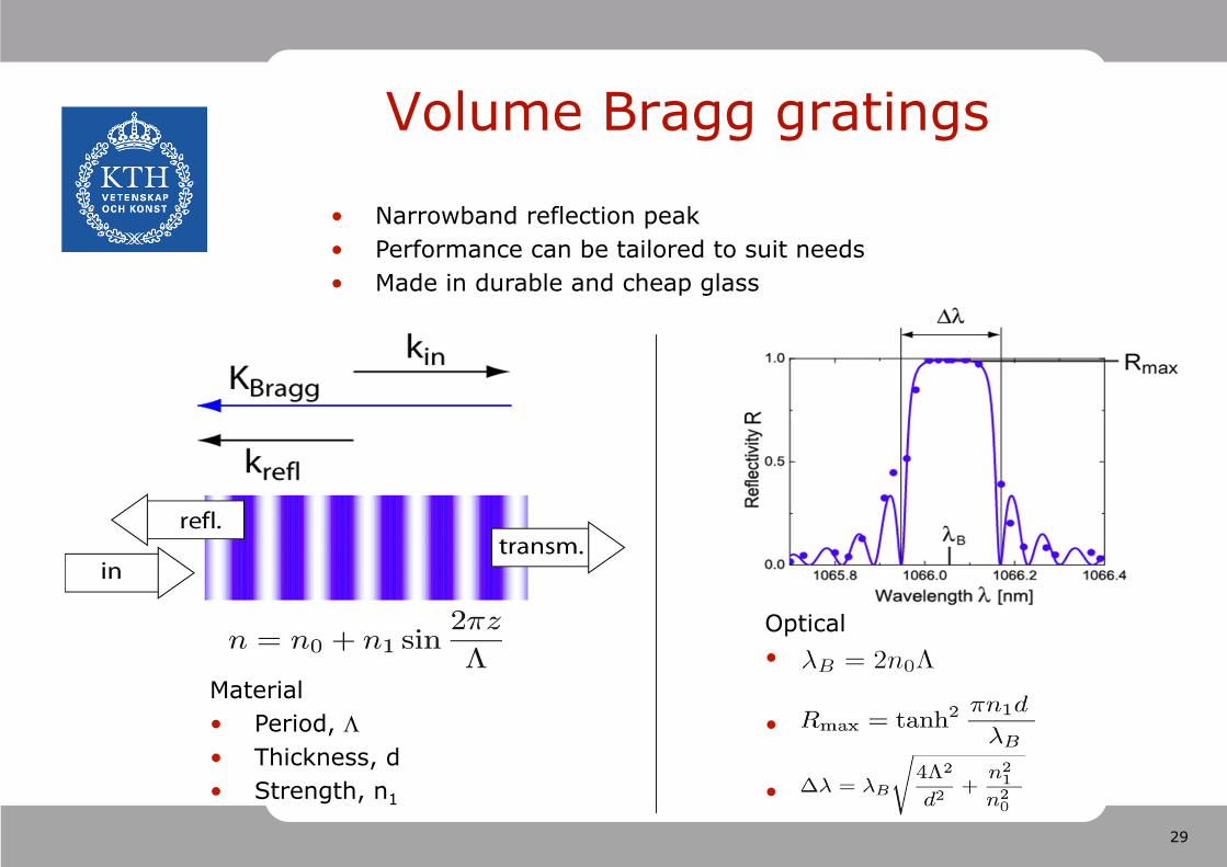
Volume Bragg gratings
Optical•
•
•
Material• Period, • Thickness, d• Strength, n1
• Narrowband reflection peak• Performance can be tailored to suit needs• Made in durable and cheap glass
30
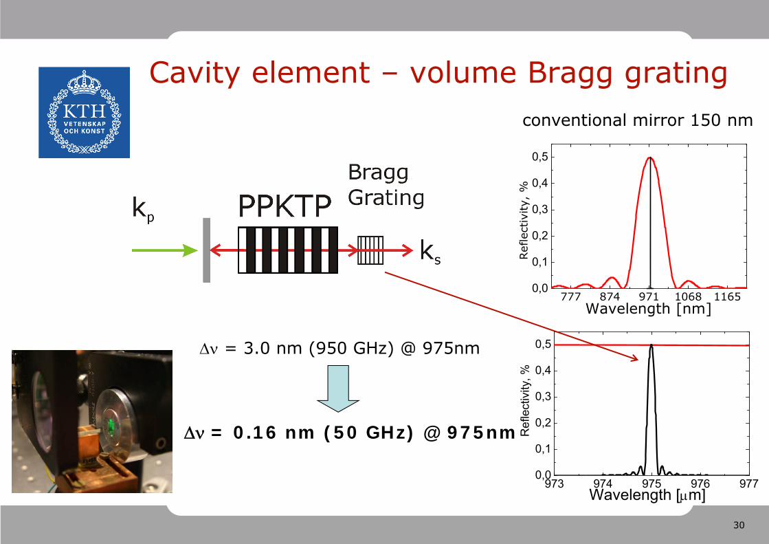
Cavity element – volume Bragg grating
777 874 971 1068 11650,0
0,1
0,2
0,3
0,4
0,5
Wavelength [nm]
Ref
lect
ivity
, %
973 974 975 976 9770,0
0,1
0,2
0,3
0,4
0,5
Wavelength [m]
Ref
lect
ivity
, %
= 0.16 nm (50 GHz) @ 975nm
= 3.0 nm (950 GHz) @ 975nm
conventional mirror 150 nm
31
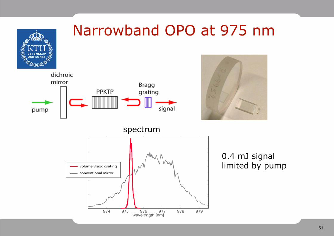
Narrowband OPO at 975 nm
spectrum
0.4 mJ signal limited by pump
32
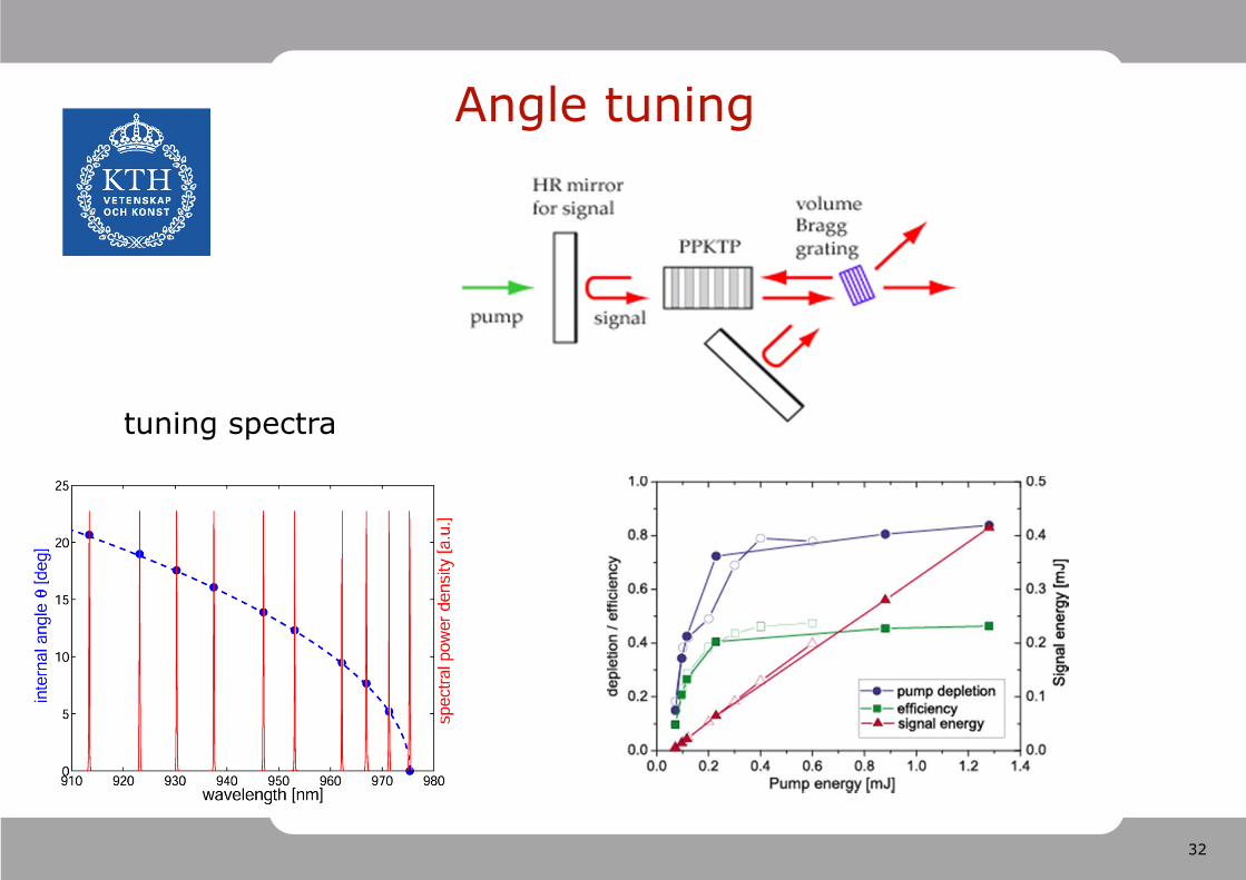
Angle tuning
tuning spectra
33
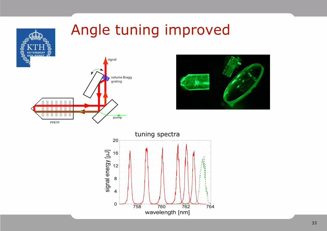
Angle tuning improved
tuning spectra
34
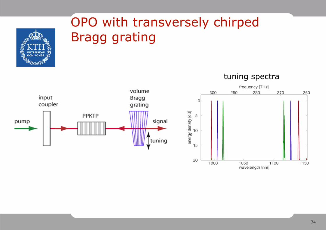
OPO with transversely chirped Bragg grating
tuning spectra
35
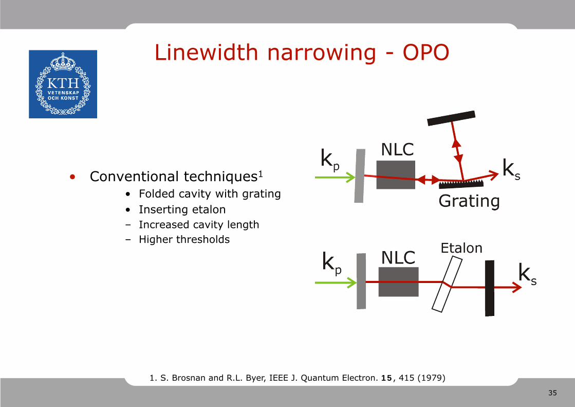
Linewidth narrowing - OPO
• Conventional techniques1
• Folded cavity with grating • Inserting etalon – Increased cavity length– Higher thresholds
1. S. Brosnan and R.L. Byer, IEEE J. Quantum Electron. 15, 415 (1979)
36
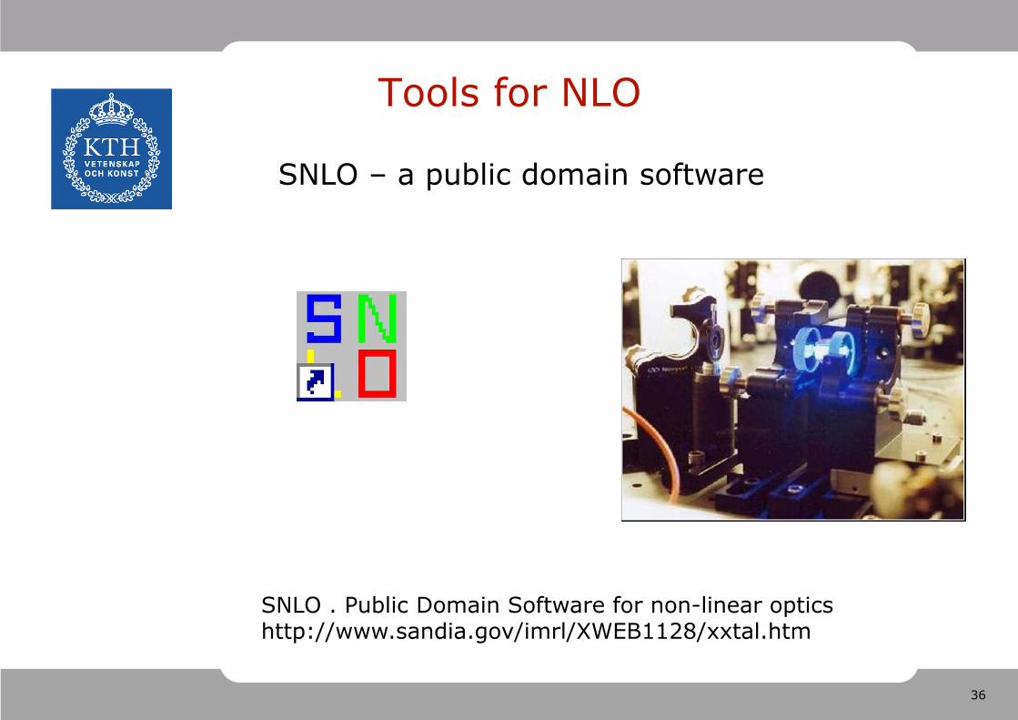
Tools for NLO
SNLO . Public Domain Software for non-linear opticshttp://www.sandia.gov/imrl/XWEB1128/xxtal.htm
SNLO – a public domain software
37
OPO with focussed Gaussian beam.
• Seminal paper:
‘Parametric interaction of focussed Gaussian light beams’Boyd and Kleinman, J. Appl. Phys. 39, 3597, (1968)
• Extension to non-degenerate OPO. Relates treatments for plane-wave, collimated Gaussian and focussed Gaussian:‘Focussing dependence of the efficiency of a singly resonant OPO’
Guha, Appl. Phys. B, 66, 663, (1998)
38
Summary: Attractions of OPOs
• Very wide continuous tuning from a single device, via tuning the phase-match condition
• High efficiency
• No heat input to the nonlinear medium
• No analogue of spatial-hole-burning as in a laser, hence simplified single-frequency operation
• Very high gain capability
• Very large bandwidth capability