npss thermodynamic property package user guide · npss™ thermodynamic property package ... 3...
TRANSCRIPT
Numerical Propulsion System Simulation Consortium
NPSS™ Thermodynamic Property Package
User Guide
Software Release: NPSSTM_2.4.1 Doc. #: NPSSTM–Thermo
Doc Revision: 2 Revision Date: June 21, 2012
© Copyright 2008, 2009, 2010, 2011, 2012.
The Ohio Aerospace Institute, on behalf of the NPSSTM Consortium. All rights reserved.
Controlled Distribution
Further distribution requires written approval of the Ohio Aerospace Institute, Cleveland, OH. Neither title nor
ownership of the software is hereby transferred.
NPSSTM software Version 2.4 and related documentation is export controlled with an Export Control Classification
Number(ECCN)of 9D991, controlled for Anti-Terrorism reasons, under U.S. Export Administration Regulations 15
CFR 730-774. It may not be transferred to a country checked under anti-terrorism on the Commerce Country Chart
structure or to foreign nationals of those countries in the U.S. or abroad without first obtaining a license from the
Bureau of Industry and Security, United States Department of Commerce. Violations are punishable by fine,
imprisonment, or both.
Disclaimer: This software is provided “as is” without any warranty of any kind, either expressed, implied, or statutory.
In no event shall NPSSTM Consortium member organizations, the Ohio Aerospace Institute., or OAI’s contractors or
subcontractors, be held liable for any damages, including, but not limited to, direct, indirect, special, or consequential
damage.
Doc. #: NPSSTM Thermo Guide
REL: 2.4.1
Date: 06/21/12
1
Table of Contents PREFACE ............................................................................................................. 3
1 ALLFUEL ...................................................................................................... 4
1.1 ALLFUELFLOWSTATION ............................................................................. 4
1.2 ALLFUELFUELSTATION .............................................................................. 9
2 CEA (CHEMICAL EQUILIBRIUM WITH APPLICATIONS)......................... 12
2.1 CEAFLOWSTATION ................................................................................. 12
2.2 CEAFUELSTATION .................................................................................. 18
3 FLUID PROPERTY TABLES ...................................................................... 21
3.1 FPTFLOWSTATION ................................................................................. 21
4 GASTBL ...................................................................................................... 25
4.1 GASTAB ............................................................................................... 25
4.2 GASEQL ............................................................................................... 26
4.3 GASEQL2 ............................................................................................. 26
4.4 GASTBLFLOWSTATION ............................................................................ 27
4.5 GASTBLFUELSTATION ............................................................................. 31
5 JANAF ......................................................................................................... 35
5.1 JANAFFLOWSTATION ............................................................................... 35
5.2 JANAFFUELSTATION ................................................................................ 40
Doc. #: NPSSTM Thermo Guide
REL: 2.4.1
Date: 06/21/12
2
List of Tables Table 1-1: allFuelFlowStation Supported Parameters ........................................... 7
Table 1-2: allFuelFlowStation Supported Functions.............................................. 9
Table 1-3: allFuelFuelStation Supported Parameters ......................................... 10
Table 1-4: allFuelFuelStation Supported Functions ............................................ 11
Table 2-1: CEAFlowStation Supported Parameters ............................................ 15
Table 2-2: CEAFlowStation Supported Functions ............................................... 17
Table 2-3: CEAFuelStation Supported Parameters ............................................ 20
Table 2-4: CEAFuelStation Supported Functions ............................................... 20
Table 3-1: FPT Supported Parameters ............................................................... 23
Table 3-2: FPT Supported Functions .................................................................. 24
Table 4-1: GASTAB Correlation Range .............................................................. 26
Table 4-2: GASEQL Correlation Range .............................................................. 26
Table 4-3: GASEQL2 Correlation Range ............................................................ 27
Table 4-4: GasTblFlowStation Supported Parameters ........................................ 29
Table 4-5: GasTblFlowStation Supported Functions........................................... 30
Table 4-6: GasTbl FuelStation Subset Options for switchGasTblOpt ................. 31
Table 4-7: Argument List for init Function ........................................................... 32
Table 4-8: GasTblFuelStation Supported Parameters ........................................ 33
Table 4-9: GasTblFuelStation Supported Functions ........................................... 34
Table 5-1: JanafFlowStation Supported Parameters .......................................... 37
Table 5-2: JanafFlowStation Supported Functions ............................................. 39
Table 5-3: JanafFuelStation Supported Parameters ........................................... 40
Table 5-4: JanafFuelStation Supported Functions .............................................. 40

Doc. #: NPSSTM Thermo Guide
REL: 2.4.1
Date: 06/21/12
3
Preface This document is a user guide for the thermal dynamic property packages and is intended to be used in
conjunction with the NPSS User Guide Reference Sheets.
Calculations involving fluid properties require a thermodynamics package that models the fluid. NPSS
offers the user the ability to choose the thermodynamics package to be used.
Doc. #: NPSSTM Thermo Guide
REL: 2.4.1
Date: 06/21/12
4
1 allFuel The allFuel thermo package defines the thermodynamic state of a gaseous mixture composed of air, water
vapor, and a variety of fuels.
1.1 allFuelFlowStation
The thermo package must be set before any FlowStation objects can be created. If the thermo package is
already set to “allFuel”, then it does not need to be set again before creating an allFuel FlowStation.
// Specify allFuel thermo package
setThermoPackage("allFuel");
// Create FlowStation(s)
FlowStation fs;
FlowStation fs2;
The allFuel thermo consists of seven switch-selectable models with a common interface. Allowed values
for fuel type in allFuel are "JP", "OLJP", "H2", "GAS", "CH4", "WBH2" and "UNIV".
// Set the flow station fuel type
fs.switchFuelType = “JP”;
Note: only "JP" and "CH4" are recommended for use.
"JP" is designed to produce properties for the combustion products of fuel, water and air, where the fuel H-
C atom ratio is 2:1. This model applies a 1962 atmosphere (with 0.03% CO2). This is a GE current
standard.
allFuel is a simple (fast) "burned properties only" thermo package. It does not keep track of the Cp, SG,
rho, etc. properties of unburned fuels. Therefore, it does not need to distinguish between JP4, JP7, JP8,
AvGas, Kerosene, etc.. The 2:1 H-C ratio value is close for all of these JP fuels.
"OLJP" stands for OLD JP and has an H-C ratio of 2:1 but with a 1945 Keenan and Keyes air composition
with no CO2 (used to match models from the 1950's to the 1990's).
"H2" stands for pure hydrogen gas with the 1962 atmosphere air composition.
"GAS" is a methane model with the 1945 Keenan and Keyes air composition. This is no longer the GE
standard.
"CH4" is the current methane model with the 1962 atmosphere air composition and is a GE standard.
"WBH2" is a pure hydrogen fuel with pure oxygen rather than air as the working fluid.
"UNIV" is a more complex option to address arbitrary fuel composition of H-C-O-N-A atoms with the
1962 atmosphere air composition. It can not be used without additional information and guidance.
Although there is a default Lower Heating Value (LHV), this parameter can vary dramatically (even for
fuels with the same H-C atom ratio) and thus should be input by the user. LHV has become problematic
and has been removed from FlowStations; it is currently only found in FuelStations.
Note: the zero enthalpy datum is at zero degrees Rankine/Kelvin (Keenan and Keyes base).

Doc. #: NPSSTM Thermo Guide
REL: 2.4.1
Date: 06/21/12
5
It is to be noted that there is a single instance of the allFuel library, and hence common allFuel information
is shared across all the FlowStation objects. The above switchFuelType is an example of a common input.
The following examples demonstrate some of the functionality of the allFuel FlowStation. A complete list
of attributes and functions supported by allFuel FlowStation appear at the end of this section.
Dissociation flag can be set to be "ON" or "OFF."
// Set dissociation flag
fs.Dissociated = “ON”;
Constituents of the FlowStation have to be set prior to calculating the total conditions.
// Set fuel-to-air ratio
fs.FAR = 0.04;
// Set water-to-air ratio (specific humidity)
fs.WAR = 0.01;
Flow rate for a FlowStation can be set as follows.
// Set total flow rate, lbm/s
fs.W = 50.;
The total conditions at a station are set by any of the following functions.
// Define total properties of the FlowStation using
// one of the functions below
// setTotalTP(Tt, Pt); // based on input temperature and pressure
// setTotalSP(s, Pt); // based on input entropy and pressure
// setTotal_hS(ht, s); // based on input entropy and entropy
// setTotal_hP(ht, Pt); // based on input enthalpy and pressure
// set total state of fluid based on temperature and pressure
fs.setTotalTP(1000,50);
// set total state of fluid based on enthalpy and pressure
fs.setTotal_hP(135,30);
// Copy FlowStation flow, composition and total properties
fs2.copyFlow("fs");
// Combine two FlowStations: flow, composition, ht and Tt are
// calculated, while Pt is carried over from the 1st FlowStation
fs.add("fs2");
Once the flow rate and total conditions have been set, the static condition can be calculated by setting any
one of the following: area (A), static enthalpy (hs), static pressure (Ps), static temperature (Ts), Velocity
(V), or Mach number (MN).
// Set Mach number. This will set the flow static conditions.
fs.MN = 0.5;
// Set duct area. This will set the flow static conditions.
fs.A = 200.;
Note that the last static property input sets the static conditions. The example above sets the Mach number
and then sets cross-sectional area. Because area is set last, the static conditions will be based on area, and
the resulting Mach number will be calculated.
Doc. #: NPSSTM Thermo Guide
REL: 2.4.1
Date: 06/21/12
6
Users will typically start the fluid flow using the FlowStart element. Therefore, they will use the FlowStart
element to set the temperature, pressure, flow rate, and water-to-air ratio. See the FlowStart element
description for additional information.
// Instantiate a FlowStart element
Element FlowStart AirStart {
// Set temperature, pressure, flow rate, and WAR
Tt = 520;
Pt = 14.7;
W = 50.;
WAR = 0.01;
}
The burn function is required in order to combine the fuel and air streams and burn the resulting mixture.
An allFuel FuelStation is required as an input argument.
// Create FuelStation
FuelStation fus;
// Set fuel station flow
fus.Wfuel = 5.;
// Burn FuelStation fuel in the FlowStation
// (use default fuel station settings)
// (use ideal efficiency for the purpose of the example)
fs.burn("fus",1);
Doc. #: NPSSTM Thermo Guide
REL: 2.4.1
Date: 06/21/12
7
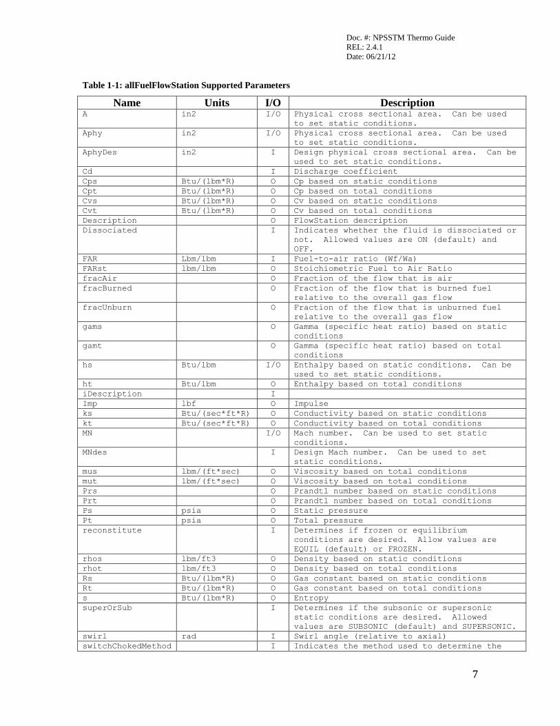
Table 1-1: allFuelFlowStation Supported Parameters
Name Units I/O Description A in2 I/O Physical cross sectional area. Can be used
to set static conditions.
Aphy in2 I/O Physical cross sectional area. Can be used
to set static conditions.
AphyDes in2 I Design physical cross sectional area. Can be
used to set static conditions.
Cd I Discharge coefficient
Cps Btu/(lbm*R) O Cp based on static conditions
Cpt Btu/(lbm*R) O Cp based on total conditions
Cvs Btu/(lbm*R) O Cv based on static conditions
Cvt Btu/(lbm*R) O Cv based on total conditions
Description O FlowStation description
Dissociated I Indicates whether the fluid is dissociated or
not. Allowed values are ON (default) and
OFF.
FAR Lbm/lbm I Fuel-to-air ratio (Wf/Wa)
FARst lbm/lbm O Stoichiometric Fuel to Air Ratio
fracAir O Fraction of the flow that is air
fracBurned O Fraction of the flow that is burned fuel
relative to the overall gas flow
fracUnburn O Fraction of the flow that is unburned fuel
relative to the overall gas flow
gams O Gamma (specific heat ratio) based on static
conditions
gamt O Gamma (specific heat ratio) based on total
conditions
hs Btu/lbm I/O Enthalpy based on static conditions. Can be
used to set static conditions.
ht Btu/lbm O Enthalpy based on total conditions
iDescription I
Imp lbf O Impulse
ks Btu/(sec*ft*R) O Conductivity based on static conditions
kt Btu/(sec*ft*R) O Conductivity based on total conditions
MN I/O Mach number. Can be used to set static
conditions.
MNdes I Design Mach number. Can be used to set
static conditions.
mus lbm/(ft*sec) O Viscosity based on total conditions
mut lbm/(ft*sec) O Viscosity based on total conditions
Prs O Prandtl number based on static conditions
Prt O Prandtl number based on total conditions
Ps psia O Static pressure
Pt psia O Total pressure
reconstitute I Determines if frozen or equilibrium
conditions are desired. Allow values are
EQUIL (default) or FROZEN.
rhos lbm/ft3 O Density based on static conditions
rhot lbm/ft3 O Density based on total conditions
Rs Btu/(lbm*R) O Gas constant based on static conditions
Rt Btu/(lbm*R) O Gas constant based on total conditions
s Btu/(lbm*R) O Entropy
superOrSub I Determines if the subsonic or supersonic
static conditions are desired. Allowed
values are SUBSONIC (default) and SUPERSONIC.
swirl rad I Swirl angle (relative to axial)
switchChokedMethod I Indicates the method used to determine the
Doc. #: NPSSTM Thermo Guide
REL: 2.4.1
Date: 06/21/12
8
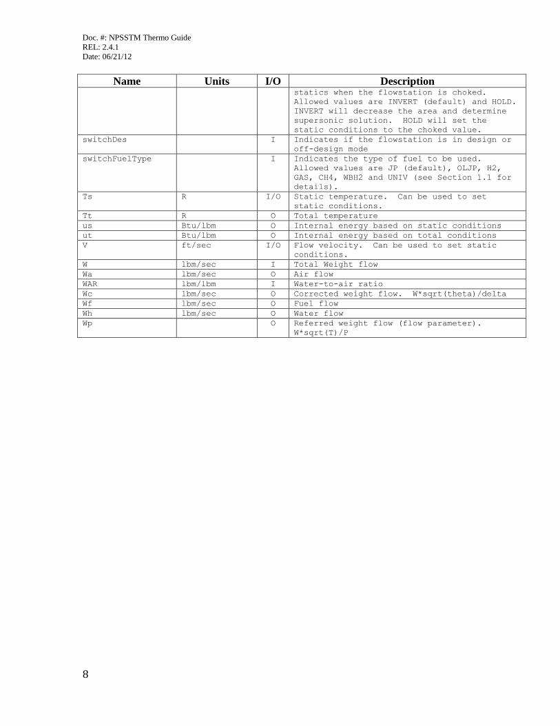
Name Units I/O Description statics when the flowstation is choked.
Allowed values are INVERT (default) and HOLD.
INVERT will decrease the area and determine
supersonic solution. HOLD will set the
static conditions to the choked value.
switchDes I Indicates if the flowstation is in design or
off-design mode
switchFuelType I Indicates the type of fuel to be used.
Allowed values are JP (default), OLJP, H2,
GAS, CH4, WBH2 and UNIV (see Section 1.1 for
details).
Ts R I/O Static temperature. Can be used to set
static conditions.
Tt R O Total temperature
us Btu/lbm O Internal energy based on static conditions
ut Btu/lbm O Internal energy based on total conditions
V ft/sec I/O Flow velocity. Can be used to set static
conditions.
W lbm/sec I Total Weight flow
Wa lbm/sec O Air flow
WAR lbm/lbm I Water-to-air ratio
Wc lbm/sec O Corrected weight flow. W*sqrt(theta)/delta
Wf lbm/sec O Fuel flow
Wh lbm/sec O Water flow
Wp O Referred weight flow (flow parameter).
W*sqrt(T)/P
Doc. #: NPSSTM Thermo Guide
REL: 2.4.1
Date: 06/21/12
9
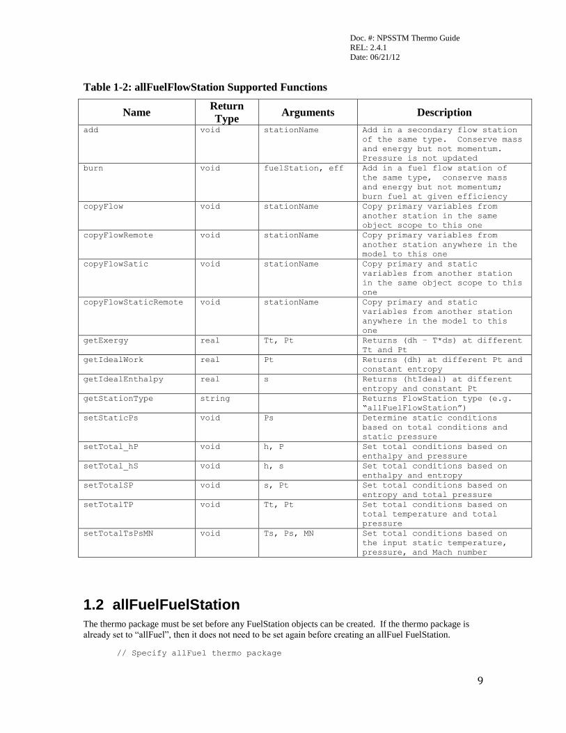
Table 1-2: allFuelFlowStation Supported Functions
Name Return
Type Arguments Description
add void stationName Add in a secondary flow station
of the same type. Conserve mass
and energy but not momentum.
Pressure is not updated
burn void fuelStation, eff Add in a fuel flow station of
the same type, conserve mass
and energy but not momentum;
burn fuel at given efficiency
copyFlow void stationName Copy primary variables from
another station in the same
object scope to this one
copyFlowRemote void stationName Copy primary variables from
another station anywhere in the
model to this one
copyFlowSatic void stationName Copy primary and static
variables from another station
in the same object scope to this
one
copyFlowStaticRemote void stationName Copy primary and static
variables from another station
anywhere in the model to this
one
getExergy real Tt, Pt Returns (dh – T*ds) at different
Tt and Pt
getIdealWork real Pt Returns (dh) at different Pt and
constant entropy
getIdealEnthalpy real s Returns (htIdeal) at different
entropy and constant Pt
getStationType string Returns FlowStation type (e.g.
“allFuelFlowStation”)
setStaticPs void Ps Determine static conditions
based on total conditions and
static pressure
setTotal_hP void h, P Set total conditions based on
enthalpy and pressure
setTotal_hS void h, s Set total conditions based on
enthalpy and entropy
setTotalSP void s, Pt Set total conditions based on
entropy and total pressure
setTotalTP void Tt, Pt Set total conditions based on
total temperature and total
pressure
setTotalTsPsMN void Ts, Ps, MN Set total conditions based on
the input static temperature,
pressure, and Mach number
1.2 allFuelFuelStation
The thermo package must be set before any FuelStation objects can be created. If the thermo package is
already set to “allFuel”, then it does not need to be set again before creating an allFuel FuelStation.
// Specify allFuel thermo package
Doc. #: NPSSTM Thermo Guide
REL: 2.4.1
Date: 06/21/12
10
setThermoPackage("allFuel");
// Create fuel station
FuelStation fus;
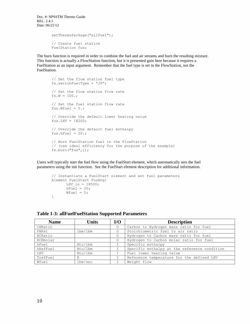
The burn function is required in order to combine the fuel and air streams and burn the resulting mixture.
This function is actually a FlowStation function, but it is presented gain here because it requires a
FuelStation as an input argument. Remember that the fuel type is set in the FlowStation, not the
FuelStation.
// Set the flow station fuel type
fs.switchFuelType = “JP”;
// Set the flow station flow rate
fs.W = 100.;
// Set the fuel station flow rate
fus.Wfuel = 5.;
// Override the default lower heating value
fus.LHV = 18200;
// Override the default fuel enthalpy
fus.hFuel = 20.;
// Burn FuelStation fuel in the FlowStation
// (use ideal efficiency for the purpose of the example)
fs.burn("fus",1);
Users will typically start the fuel flow using the FuelStart element, which automatically sets the fuel
parameters using the init function. See the FuelStart element description for additional information.
// Instantiate a FuelStart element and set fuel parameters
Element FuelStart FusEng{
LHV_in = 18500;
hFuel = 20;
Wfuel = 5;
}
Table 1-3: allFuelFuelStation Supported Parameters
Name Units I/O Description CHRatio O Carbon to Hydrogen mass ratio for fuel
FARst lbm/lbm O Stoichiometric fuel to air ratio
HCRatio O Hydrogen to Carbon mass ratio for fuel
HCRmolar O Hydrogen to Carbon molar ratio for fuel
hFuel Btu/lbm I Specific enthalpy
hRefFuel Btu/lbm I Specific enthalpy at the reference condition
LHV Btu/lbm I Fuel lower heating value
TrefFuel R I Reference temperature for the defined LHV
Wfuel lbm/sec I Weight flow

Doc. #: NPSSTM Thermo Guide
REL: 2.4.1
Date: 06/21/12
11
Table 1-4: allFuelFuelStation Supported Functions
Name Return Type Arguments Description
copyFlow void stationName
Copy fuel properties (hRefFuel,
hFuel, Pfuel, TrefFuel, Tfuel,
and Wfuel) from another station
to this one
Init void dummyFuelType,
LHVin, Tstor, Pstor,
hstor, Tref, href,
Carbon, Hydrogen,
Nitrogen2, Oxygen
Initializes the FuelStation
Doc. #: NPSSTM Thermo Guide
REL: 2.4.1
Date: 06/21/12
12
2 CEA (Chemical Equilibrium with Applications) CEA is a program which calculates chemical equilibrium composition from any set of reactants and
determines thermodynamic and transport properties for that composition.
CEA allows users to specify mixtures made up of any species. The possible reactants and products are
defined in the file thermo.inp. The reactants are defined in terms of the atomic ratios of their components.
When performing thermodynamic calculations (and solving for equilibrium), CEA will add all the reactants
together to determine the atomic ratio of the mix. It will then determine the mixture composition and
thermodynamic properties based on minimizing the product’s Gibbs free energy.
CEA will also calculate the transport properties of a mixture. The transport properties can be based on
frozen or equilibrium mixture compositions. For frozen properties, the assumption is made that the mixture
composition does not change as the derivatives are calculated (derivatives are used to obtain the values for
Cp, conductivity and Prandtl number). For equilibrium results, the assumption is made that the products do
change as the derivatives are calculated.
CEA allows users to specify a Mach number at which the static composition will be determined, different
from the actual static conditions. This allows users to simulate frozen flow through a nozzle expansion
process. Setting the composition Mach number at 0 is equivalent to fixing the mixture composition at the
stagnation conditions, upstream of the throat. Setting the Mach number to 1.0 is equivalent to freezing the
flow composition at the throat.
CEA allows users to remove reactants from a flow. This is equivalent to a product precipitating out of the
flow. An example of this would be water forming in a flow and precipitating out.
Normally CEA calculates the full equilibrium solution of given reactants. However, it may be desirable to
simulate incomplete reactions for such things as combustion inefficiencies. This is allowed by specifying
inert versions of the reactants. These inert reactants are thermodynamically the same as the true reactants.
The difference is they are not allowed to react with the rest of the flow. For example, the standard
thermo.inp file released with CEA contains an inert version of JP7. This JP7 does not combust with
oxygen; however, it can break down into inert versions of C2H4 and C8H10 that can not react with
anything else, unless additional inert species are added to the thermo.inp file.
For more technical information on CEA (including history and links to various technical reports concerning
CEA and its predecessors), see the website:
http://www.grc.nasa.gov/WWW/CEAWeb/ceaHome.htm
2.1 CEAFlowStation
To use CEA, the files thermo.inp and trans.inp must be in the include path. These are the default files that
define the thermodynamic and transport properties for the possible reactants and products. A complete list
of reactants can be found in the file thermo.inp, which is typically located in the NPSS “InterpIncludes”
directory.
The amount of time it takes CEA to converge is proportional the size of the thermo.inp file. NPSS is
released with two thermo input files, thermo.small and thermo.inp. The file thermo.small contains the
compounds associated with the combustion of a hydrocarbon fuel and air. The file thermo.inp contains a
large set of different compounds. If users wish to optimize CEA runs for speed, they should specify the
thermo.small file or create a new thermo file that is representative of the compounds that are pertinent to
the problem at hand.
Doc. #: NPSSTM Thermo Guide
REL: 2.4.1
Date: 06/21/12
13
The CEA package itself is invoked using the setThermoPackage command.
// Specify CEA thermo package and allowable reactants
setThermoPackage("CEA", "thermo.inp", "trans.inp", "Air", "H2O", "JP_7",
"O2", "N2" );
// Create FlowStation
FlowStation fs;
The first argument sets the thermo package to "CEA", the second argument specifies the thermo property
file to use, the third argument specifies the transport property file to use, and the fourth argument is the first
reactant. Up to ten reactants can be specified. When running aircraft engine problems, the first reactant
should be air, and the second reactant should be water ("H2O"). This is because the elements that start the
flow will make this assumption when defining the air and humidity. When defining the fuel, the fuelType
variable in the FuelStart element must be set equal to one of the reactants listed above. The fuel enthalpy is
determined based on the heat of formation of the reactants. With these two changes – the
setThermoPackage and the fuel being defined correctly in the FuelStart – a standard NPSS model that was
running with a different thermo package should run with CEA.
Constituents of the flowstation have to be set prior to calculating the total conditions. Water-to-air ratio
can be set as follows.
// Set water-to-air ratio (specific humidity)
fs.WAR = 0.01;
Flow rate for a FlowStation can be set as follows.
// Set total flow rate, lbm/s
fs.W = 50.;
The total conditions at a station are set by any of the following setTotalxx functions.
// Define total properties of the FlowStation using
// one of the functions below
// setTotalTP(Tt, Pt); // based on input temperature and pressure
// setTotalSP(s, Pt); // based on input entropy and pressure
// setTotal_hS(ht, s); // based on input entropy and entropy
// setTotal_hP(ht, Pt); // based on input enthalpy and pressure
// set total state of fluid based on temperature and pressure
fs.setTotalTP(1000,50);
Once the flow rate and total conditions have been set, the static condition can be calculated by setting any
of the following: area (A), static enthalpy (hs), static pressure (Ps), static temperature (Ts), Velocity (V), or
Mach number (MN).
// Set Mach number. This will set the flow static conditions.
fs.MN = 0.5;
// Set duct area. This will set the flow static conditions.
fs.A = 200.;
Note that the last static property input sets the static conditions. The example above sets the Mach number
and then sets cross-sectional area. Because area is set last, the static conditions will be based on area, and
the resulting Mach number will be calculated.
To see the CEA output conditions set the switchPrint option to TRUE for that FlowStation. When this is
done, NPSS will produce CEA output files for the FlowStation. These files are <flowstationname>.ceaout
Doc. #: NPSSTM Thermo Guide
REL: 2.4.1
Date: 06/21/12
14
and <flowstationname>.ceaoutStatic. The first file is the thermodynamic properties at the total conditions.
The second file is the thermodynamic properties at the static conditions (if they are calculated). IT IS
IMPORTANT THAT THESE FILES BE CHECKED PERIODICALLY TO ENSURE THE
THERMODYNAMIC CALCULATIONS ARE BEING PERFORMED CORRECTLY!
// Save flow station output conditions to the files fs.ceaout
// and fs.ceaoutStatic (if statics are calculated)
fs.setOption(“switchPrint”, “TRUE”);
// set the total state of the fluid using total temp and pressure
fs.setTotalTP(600., 30.);
// set the static state of the fluid using known static pressure
fs.Ps = 24.;
For CEA to calculate transport properties (specific heat, viscosity, thermal conductivity, etc.), the
FlowStation option variable switchTransport must be set to either EQUIL or FROZEN (default is NONE).
It is recommended that switchTransport be set only for FlowStations that require the retrieval of transport
properties and not for all FlowStations in the model.
// Enable the flow station to calculate transport properties
// at equilibrium
fs.setOption(“switchTransport”, “EQUIL”);
// set the fluid state using temperature and pressure
fs.setTotalTP(550., 15.);
// save the thermal conductivity as ktIn
real ktIn = fs.kt;
Simulating frozen composition flow is a two-step process. First, the user sets the reconstitute option to
FROZEN. Then, the user specifies the desired Mach number. The following example will freeze the flow
at the total conditions:
// Set the flow conditions to FROZEN
fs.setOption(“reconstitute”, “FROZEN”);
// Set the frozen Mach number
fs.MNfroz = 0.;
The function addNonEq(string comp, real W) adds flow rate W amount of compound type comp to the
flow. When this is done, equilibrium is not recalculated. The thermodynamics are based on the previous
mix plus the new compound. Note: comp must be defined as a reactant in the setThermoPackage
command. Also, since equilibrium is not redone, comp must be available as a product.
// Add 3 lbm/s of H2O to the flow
// Do not recalculate equilibrium
fs.addNonEq("H2O", 3.);
The function addEq(string comp, real W) adds flow rate W amount of compound type comp to the flow.
When this is done, equilibrium is recalculated. As such, the final amount of compound comp may be
different than the initial amount plus W as more/less may form as the solution rebalances. Constant
temperature is assumed. Note: comp must be defined as a reactant in the setThermoPackage command.
// Add 5 lbm/s of H2O to the flow
// Recalculate equilibrium
fs.addEq("H2O", 5.);
Doc. #: NPSSTM Thermo Guide
REL: 2.4.1
Date: 06/21/12
15
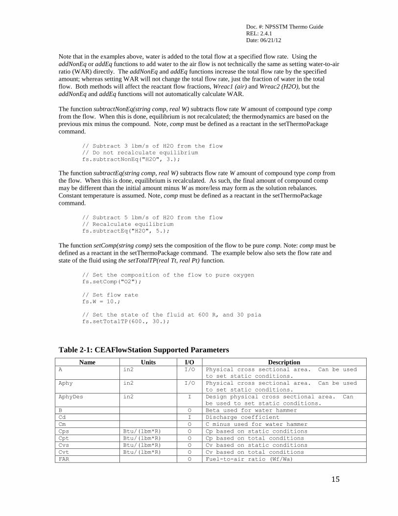
Note that in the examples above, water is added to the total flow at a specified flow rate. Using the
addNonEq or addEq functions to add water to the air flow is not technically the same as setting water-to-air
ratio (WAR) directly. The addNonEq and addEq functions increase the total flow rate by the specified
amount; whereas setting WAR will not change the total flow rate, just the fraction of water in the total
flow. Both methods will affect the reactant flow fractions, Wreac1 (air) and Wreac2 (H2O), but the
addNonEq and addEq functions will not automatically calculate WAR.
The function subtractNonEq(string comp, real W) subtracts flow rate W amount of compound type comp
from the flow. When this is done, equilibrium is not recalculated; the thermodynamics are based on the
previous mix minus the compound. Note, comp must be defined as a reactant in the setThermoPackage
command.
// Subtract 3 lbm/s of H2O from the flow
// Do not recalculate equilibrium
fs.subtractNonEq("H2O", 3.);
The function subtractEq(string comp, real W) subtracts flow rate W amount of compound type comp from
the flow. When this is done, equilibrium is recalculated. As such, the final amount of compound comp
may be different than the initial amount minus W as more/less may form as the solution rebalances.
Constant temperature is assumed. Note, comp must be defined as a reactant in the setThermoPackage
command.
// Subtract 5 lbm/s of H2O from the flow
// Recalculate equilibrium
fs.subtractEq("H2O", 5.);
The function setComp(string comp) sets the composition of the flow to be pure comp. Note: comp must be
defined as a reactant in the setThermoPackage command. The example below also sets the flow rate and
state of the fluid using the setTotalTP(real Tt, real Pt) function.
// Set the composition of the flow to pure oxygen
fs.setComp("O2");
// Set flow rate
fs.W = 10.;
// Set the state of the fluid at 600 R, and 30 psia
fs.setTotalTP(600., 30.);
Table 2-1: CEAFlowStation Supported Parameters
Name Units I/O Description A in2 I/O Physical cross sectional area. Can be used
to set static conditions.
Aphy in2 I/O Physical cross sectional area. Can be used
to set static conditions.
AphyDes in2 I Design physical cross sectional area. Can
be used to set static conditions.
B O Beta used for water hammer
Cd I Discharge coefficient
Cm O C minus used for water hammer
Cps Btu/(lbm*R) O Cp based on static conditions
Cpt Btu/(lbm*R) O Cp based on total conditions
Cvs Btu/(lbm*R) O Cv based on static conditions
Cvt Btu/(lbm*R) O Cv based on total conditions
FAR O Fuel-to-air ratio (Wf/Wa)
Doc. #: NPSSTM Thermo Guide
REL: 2.4.1
Date: 06/21/12
16
Name Units I/O Description gams O Gamma (specific heat ratio) based on static
conditions
gamt O Gamma (specific heat ratio) based on total
conditions
hs Btu/lbm O Enthalpy based on static conditions. Can be
used to set static conditions.
ht Btu/lbm O Enthalpy based on total conditions.
iDescription I
inertBurnReac1 I Percentage of reactant 1 to be moved to
reactant 10 (inerted) during a burn
inertBurnReac2 I Percentage of reactant 2 to be moved to
reactant 10 (inerted) during a burn
inertBurnReac3 I Percentage of reactant 3 to be moved to
reactant 10 (inerted) during a burn
inertBurnReac4 I Percentage of reactant 4 to be moved to
reactant 10 (inerted) during a burn
inertBurnReac5 I Percentage of reactant 5 to be moved to
reactant 10 (inerted) during a burn
inertBurnReac6 I Percentage of reactant 6 to be moved to
reactant 10 (inerted) during a burn
inertBurnReac7 I Percentage of reactant 7 to be moved to
reactant 10 (inerted) during a burn
inertBurnReac8 I Percentage of reactant 8 to be moved to
reactant 10 (inerted) during a burn
inertBurnReac9 I Percentage of reactant 9 to be moved to
reactant 10 (inerted) during a burn
inertBurnReac10 I Percentage of reactant 10 to be moved to
reactant 10 (inerted) during a burn
ks Btu/(sec*ft*R) O Conductivity based on static conditions
kt Btu/(sec*ft*R) O Conductivity based on total conditions
MN I/O Mach number. Can be used to set static
conditions.
MNdes I Design Mach number. Can be used to set
static conditions.
MNfroz I Mach number used to freeze the flow
mus lbm/(ft*sec) O Viscosity based on total conditions
mut lbm/(ft*sec) O Viscosity based on total conditions
MW O Molecular weight
Ps psia I/O Static pressure. Can be used to set static
conditions.
Pt psia O Total pressure
reac1 O Name of reac1 (Air)
reac2 O Name of reac2 (H2O)
reac3 O Name of reac3 (empty)
reac4 O Name of reac4 (empty)
reac5 O Name of reac5 (empty)
reac6 O Name of reac6 (empty)
reac7 O Name of reac7 (empty)
reac8 O Name of reac8 (empty)
reac9 O Name of reac9 (empty)
reac10 O Name of reac10 (empty)
reconstitute I Determines if frozen or equilibrium
conditions are desired. Allow values are
EQUIL (default) or FROZEN.
rhos lbm/ft3 O Density based on static conditions
rhot lbm/ft3 O Density based on total conditions
Rs Btu/(lbm*R) O Gas constant based on static conditions
Rt Btu/(lbm*R) O Gas constant based on total conditions
s Btu/(lbm*R) O Entropy

Doc. #: NPSSTM Thermo Guide
REL: 2.4.1
Date: 06/21/12
17
Name Units I/O Description swirl rad I Swirl angle (relative to axial)
switchDes I Indicates if the flowstation is in design or
off-design mode
switchPrint I When set to TRUE, NPSS will produce standard
CEA output files: .ceaout for the total
conditions, .ceaoutStatic for the static
conditions. Allowed values are FALSE
(default) and TRUE.
switchTransport I Determines if the transport properties are
calculated (i.e. Cp, k, mu). Allowed values
are NONE (default), EQUIL, and FROZEN
Ts R O Static temperature. Can be used to set
static conditions.
Tt R O Total temperature
us Btu/lbm O Internal energy based on static conditions
ut Btu/lbm O Internal energy based on total conditions
V ft/sec I/O Flow velocity. Can be used to set static
conditions.
W lbm/sec I Total Weight flow
Wa lbm/sec O Air flow
WAR lbm/lbm I Water-to-air ratio
Wc lbm/sec O Corrected weight flow. W*sqrt(theta)/delta
Wf lbm/sec O Fuel flow
Wh lbm/sec O Water flow
Wp O Referred weight flow (flow parameter).
W*sqrt(T)/P
Wreac1 O Fraction of the flow that is Wreac1 (Air)
Wreac2 O Fraction of the flow that is Wreac2 (H2O)
Wreac3 O Fraction of the flow that is Wreac3
Wreac4 O Fraction of the flow that is Wreac4
Wreac5 O Fraction of the flow that is Wreac5
Wreac6 O Fraction of the flow that is Wreac6
Wreac7 O Fraction of the flow that is Wreac7
Wreac8 O Fraction of the flow that is Wreac8
Wreac9 O Fraction of the flow that is Wreac9
Wreac10 O Fraction of the flow that is Wreac10
Table 2-2: CEAFlowStation Supported Functions
Name Return Type Arguments Description add void stationName Add in a secondary flow station
of the same type. Conserve mass
and energy but not momentum.
Pressure is not updated
addNonEq void comp, W Adds W amount of compound type
comp to the flow. Equilibrium is
not recalculated. See Usage
Notes above for further
description.
addEq void comp, W Adds W amount of compound type
comp to the flow. Equilibrium is
recalculated. See Usage Notes
above for further description.
burn void fuelStation,
eff
Add in a fuel flow station of the
same type, conserve mass and
energy but not momentum; burn
fuel, but efficiency is NOT USED.
Doc. #: NPSSTM Thermo Guide
REL: 2.4.1
Date: 06/21/12
18
Name Return Type Arguments Description copyFlow void stationName Copy primary variables from
another station in the same
object scope to this one
copyFlowRemote void stationName Copy primary variables from
another station anywhere in the
model to this one
copyFlowSatic void stationName Copy primary and static variables
from another station in the same
object scope to this one
copyFlowStaticRemote void stationName Copy primary and static variables
from another station anywhere in
the model to this one
setComp void comp Sets the composition of the flow
to be pure comp. See Usage Notes
above for further description.
setStaticPs void Ps Determine static conditions based
on total conditions and static
pressure
setTotal_hP void h, P Set total conditions based on
enthalpy and pressure
setTotal_hS void h, s Set total conditions based on
enthalpy and entropy
setTotal_hsPsV void hs, Ps, V Set total conditions based on the
input static enthalpy, pressure,
and velocity
setTotalSP void s, Pt Set total conditions based on
entropy and total pressure
setTotalTP void Tt, Pt Set total conditions based on
total temperature and total
pressure
setTotalTsPsMN void Ts, Ps, MN Set total conditions based on the
input static temperature,
pressure, and Mach number
subtractNonEq void comp, W Subtracts W amount of compound
type comp from the flow.
Equilibrium is not recalculated.
See Usage Notes above for further
description.
subtractEq void comp, W Subtracts W amount of compound
type comp from the flow.
Equilibrium is recalculated. See
Usage Notes above for further
description.
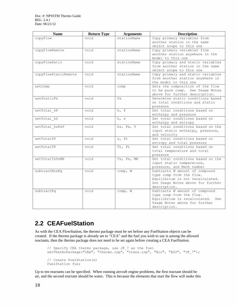
2.2 CEAFuelStation
As with the CEA FlowStation, the thermo package must be set before any FuelStation objects can be
created. If the thermo package is already set to “CEA” and the fuel you wish to use is among the allowed
reactants, then the thermo package does not need to be set again before creating a CEA FuelStation.
// Specify CEA thermo package, use JP_7 as the fuel
setThermoPackage("CEA", "thermo.inp", "trans.inp", "Air", "H2O", "JP_7");
// Create FuelStation(s)
FuelStation fus;
Up to ten reactants can be specified. When running aircraft engine problems, the first reactant should be
air, and the second reactant should be water. This is because the elements that start the flow will make this
Doc. #: NPSSTM Thermo Guide
REL: 2.4.1
Date: 06/21/12
19
assumption when defining the air and humidity. The fluid used for the fuel is typically specified as the
third reactant, after air and water.
For the CEA FuelStation the only pertinent inputs are the fuel type and heat of formation. These values are
used to initialize the fuel by means of the FuelStation function init(string fuelType, real LHV, real Tfuel,
real Pfuel, real hFuel, real TrefFuel, real hRefFuel, real Carbon, real Hydrogen, real Nitrogen2, real
Oxygen). No other inputs will have any thermodynamic effect. (Pfuel and Tfuel are used for display only,
and the other values are for other NPSS thermo packages.) The fuelType is the fuel to be burned, and it
must correspond to a reactant as defined in the CEA setThermoPackage command. The parameter hFuel is
the heat of formation of the fuel at the desired fuel temperature. When switching between CEA and the
other packages, expect to make very large changes in the hFuel value.
// Set fuel type and heat of formation using the init function
fus.init(“JP_7”, 0., 0., 0., -200., 0., 0., 0., 0., 0., 0.);
// heat of formation can also be set directly in the fuel station
fus.hFuel = -200.;
// Define fuel flow of the FuelStation
fus.Wfuel = 5.;
// Burn FuelStation fuel in the FlowStation
// In CEA, efficiency argument is ignored
fs.burn("fus",1);
Users typically do not have to call the FuelStation init function directly because the FuelStation conditions
are set in the FuelStart element as fuelType and hFuel. The FuelStart element will automatically initialize
the FuelStation using fuelType and hFuel. See the FuelStart element description for additional information.
// Instantiate a FuelStart element and set fuel parameters
Element FuelStart FusEng{
fuelType = “JP_7”;
hFuel = -200.;
Wfuel = 5;
}
If users wish to inert any of the fuel to simulate incomplete combustion, then the variable
inertBurnReac<number> is set equal to the fraction of the fuel the users wish to render inert in the
FlowStation where combustion occurs. The value of <number> must correspond to the reactant number of
the fuel that is to be rendered inert. In most cases, this will be three, since the first two reactants default to
air and water. When using this option, the tenth reactant in the setThermoPackage command must
correspond to the inert version of the fuel. NPSS will then use the tenth slot to manage the inert reactant.
// Specify CEA thermo package, use JP_7 as the fuel
// Set the tenth reactant as the inert fuel
setThermoPackage("CEA", "thermo.inp", "trans.inp", "Air", "H2O", "JP_7",
"", "", "", "", "", "", "Inert_JP_7" );
// Create FlowStation(s)
FlowStation fs;
// Set the fraction of fuel to be inert
fs.inertBurnReac3 = 0.02; // corresponds to 3rd reactant, JP_7
For the standard Burner element, the FlowStation where combustion occurs is Fl_Ocomb. Users would
directly set the inertBurn<number> parameter for Fl_Ocomb in the Burner element. When using CEA,
this method is used instead of setting the burner efficiency value. For example, if burner efficiency is 98%,
users would set the FlowStation inertBurnReac<number> value to 0.02.
// Set the burner combustion flow station inert fuel fraction
BrnPri.Fl_Ocomb.inertBurnReac3 = 0.02; // corresponds to 3rd
Doc. #: NPSSTM Thermo Guide
REL: 2.4.1
Date: 06/21/12
20
// reactant, JP_7
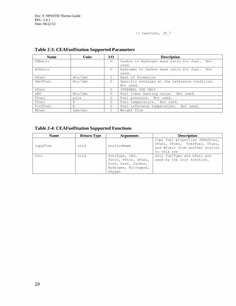
Table 2-3: CEAFuelStation Supported Parameters
Name Units I/O Description CHRatio O Carbon to Hydrogen mass ratio for fuel. Not
used.
HCRatio O Hydrogen to Carbon mass ratio for fuel. Not
used.
hFuel Btu/lbm I Heat of formation
hRefFuel Btu/lbm O Specific enthalpy at the reference condition.
Not used.
kFuel O INTERNAL USE ONLY
LHV Btu/lbm O Fuel lower heating value. Not used.
Pfuel psia O Fuel pressure. Not used.
Tfuel R O Fuel temperature. Not used.
TrefFuel R O Fuel reference temperature. Not used.
Wfuel lbm/sec I Weight flow
Table 2-4: CEAFuelStation Supported Functions
Name Return Type Arguments Description
copyFlow void stationName
Copy fuel properties (hRefFuel,
hFuel, Pfuel, TrefFuel, Tfuel,
and Wfuel) from another station
to this one
Init void fuelType, LHV,
Tstor, PStor, hFuel,
Tref, href, Carbon,
Hydrogen, Nitrogen2,
Oxygen
Only fuelType and hFuel are
used by the init function.
Doc. #: NPSSTM Thermo Guide
REL: 2.4.1
Date: 06/21/12
21
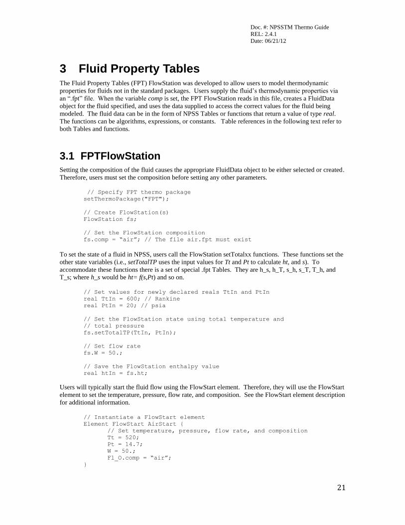
3 Fluid Property Tables The Fluid Property Tables (FPT) FlowStation was developed to allow users to model thermodynamic
properties for fluids not in the standard packages. Users supply the fluid’s thermodynamic properties via
an “.fpt” file. When the variable comp is set, the FPT FlowStation reads in this file, creates a FluidData
object for the fluid specified, and uses the data supplied to access the correct values for the fluid being
modeled. The fluid data can be in the form of NPSS Tables or functions that return a value of type real.
The functions can be algorithms, expressions, or constants. Table references in the following text refer to
both Tables and functions.
3.1 FPTFlowStation
Setting the composition of the fluid causes the appropriate FluidData object to be either selected or created.
Therefore, users must set the composition before setting any other parameters.
// Specify FPT thermo package
setThermoPackage("FPT");
// Create FlowStation(s)
FlowStation fs;
// Set the FlowStation composition
fs.comp = “air”; // The file air.fpt must exist
To set the state of a fluid in NPSS, users call the FlowStation setTotalxx functions. These functions set the
other state variables (i.e., setTotalTP uses the input values for Tt and Pt to calculate ht, and s). To
accommodate these functions there is a set of special .fpt Tables. They are h_s, h_T, s_h, s_T, T_h, and
T_s; where h_s would be ht= f(s,Pt) and so on.
// Set values for newly declared reals TtIn and PtIn
real TtIn = 600; // Rankine
real PtIn = 20; // psia
// Set the FlowStation state using total temperature and
// total pressure
fs.setTotalTP(TtIn, PtIn);
// Set flow rate
fs.W = 50.;
// Save the FlowStation enthalpy value
real htIn = fs.ht;
Users will typically start the fluid flow using the FlowStart element. Therefore, they will use the FlowStart
element to set the temperature, pressure, flow rate, and composition. See the FlowStart element description
for additional information.
// Instantiate a FlowStart element
Element FlowStart AirStart {
// Set temperature, pressure, flow rate, and composition
Tt = 520;
Pt = 14.7;
W = 50.;
Fl_O.comp = “air”;
}
Doc. #: NPSSTM Thermo Guide
REL: 2.4.1
Date: 06/21/12
22
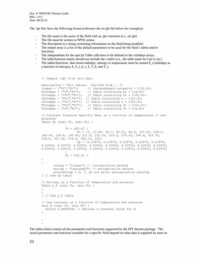
The .fpt files have the following format (reference the air.fpt file below for examples):
- The file name is the name of the fluid with an .fpt extension (i.e., air.fpt)
- The file must be written in NPSS syntax.
- The description is a string containing information on the fluid being modeled.
- The indeps array is a list of the default parameters to be used for the fluid’s tables and/or
functions.
- The independents for the special Table calls have to be defined in the xxIndeps arrays.
- The table/function names should not include the t suffix (i.e., the table name for Cpt is Cp.)
- The tables/functions that return enthalpy, entropy or temperature must be named h_s (enthalpy as
a function of entropy), h_T, s_h, s_T, T_h, and T_s.
// Sample .fpt file (air.fpt)
description = "Air tables. Derived from …. ";
indeps = {"Tt","Pt"}; // thermodynamic property = f(Tt,Pt)
hsIndeps = {"s","Pt"}; // Table containing ht = f(s,Pt)
hTindeps = {"Tt","Pt"}; // Table containing ht = f(Tt,Pt)
shIndeps = {"ht","Pt"}; // Table containing s = f(ht,Pt)
sTindeps = {"Tt","Pt"}; // Table containing s = f(Tt,Pt)
ThIndeps = {"ht","Pt"}; // Table containing Tt = f(ht,Pt)
TsIndeps = {"s","Pt"}; // Table containing Tt = f(s,Pt)
// Constant Pressure Specific Heat as a function of temperature // and
pressure
Table Cp (real Tt, real Pt) {
Tt = 455.67 {
Pt = {3, 23.85, 44.7, 65.55, 86.4, 107.25, 128.1,
148.95, 169.8, 190.65, 211.5, 232.35, 253.2, 274.05, 294.9, 315.75,
336.6, 357.45, 378.3, 399.15, 420}
Cp = {0.23976, 0.23976, 0.23976, 0.23976, 0.23976,
0.23976, 0.23976, 0.23976, 0.23976, 0.23976, 0.23976, 0.23976, 0.23976,
0.23976, 0.23976, 0.23976, 0.23976, 0.23976, 0.23976, 0.23976, 0.23976}
}
Tt = 535.87 {
…
…
interp = "linear"; // interpolation method
extrap = "lagrange2"; // extrapolation method
printExtrap = 0; // do not print extrapolation warning
} // end Cp table
// Entropy as a function of temperature and pressure
Table s_T (real Tt, real Pt) {
…
…
} // end s_T table
// Gas constant as a function of temperature and pressure
real R (real Tt, real Pt) {
return 0.0685604; // Returns a constant value for R
}
…
…
The tables listed contain all the parameters and functions supported by the FPT thermo package. The
actual parameters and functions available for a specific fluid depend on what data is supplied by users in
Doc. #: NPSSTM Thermo Guide
REL: 2.4.1
Date: 06/21/12
23
the .fpt file. Due to a problem in the internal setStatic function, the current version of FPT does not support
statics.
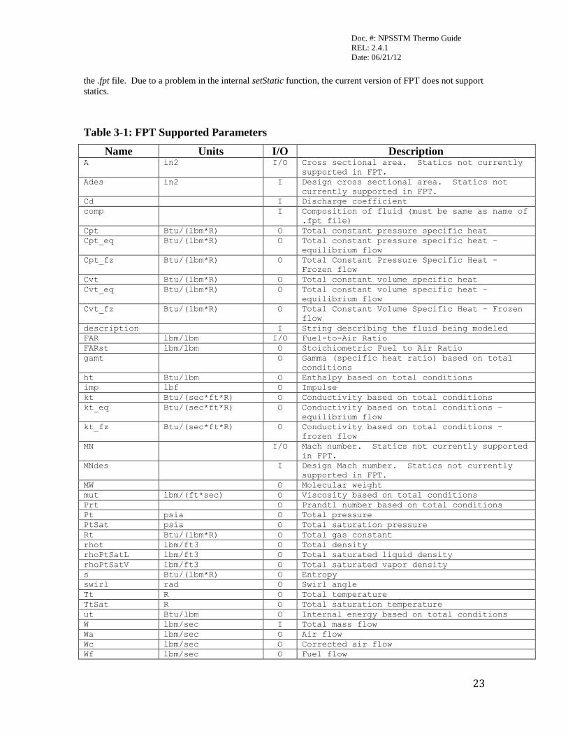
Table 3-1: FPT Supported Parameters
Name Units I/O Description A in2 I/O Cross sectional area. Statics not currently
supported in FPT.
Ades in2 I Design cross sectional area. Statics not
currently supported in FPT.
Cd I Discharge coefficient
comp I Composition of fluid (must be same as name of
.fpt file)
Cpt Btu/(lbm*R) O Total constant pressure specific heat
Cpt_eq Btu/(lbm*R) O Total constant pressure specific heat –
equilibrium flow
Cpt_fz Btu/(lbm*R) O Total Constant Pressure Specific Heat –
Frozen flow
Cvt Btu/(lbm*R) O Total constant volume specific heat
Cvt_eq Btu/(lbm*R) O Total constant volume specific heat –
equilibrium flow
Cvt_fz Btu/(lbm*R) O Total Constant Volume Specific Heat – Frozen
flow
description I String describing the fluid being modeled
FAR lbm/lbm I/O Fuel-to-Air Ratio
FARst lbm/lbm O Stoichiometric Fuel to Air Ratio
gamt O Gamma (specific heat ratio) based on total
conditions
ht Btu/lbm O Enthalpy based on total conditions
imp lbf O Impulse
kt Btu/(sec*ft*R) O Conductivity based on total conditions
kt_eq Btu/(sec*ft*R) O Conductivity based on total conditions –
equilibrium flow
kt_fz Btu/(sec*ft*R) O Conductivity based on total conditions –
frozen flow
MN I/O Mach number. Statics not currently supported
in FPT.
MNdes I Design Mach number. Statics not currently
supported in FPT.
MW O Molecular weight
mut lbm/(ft*sec) O Viscosity based on total conditions
Prt O Prandtl number based on total conditions
Pt psia O Total pressure
PtSat psia O Total saturation pressure
Rt Btu/(lbm*R) O Total gas constant
rhot lbm/ft3 O Total density
rhoPtSatL lbm/ft3 O Total saturated liquid density
rhoPtSatV lbm/ft3 O Total saturated vapor density
s Btu/(lbm*R) O Entropy
swirl rad O Swirl angle
Tt R O Total temperature
TtSat R O Total saturation temperature
ut Btu/lbm O Internal energy based on total conditions
W lbm/sec I Total mass flow
Wa lbm/sec O Air flow
Wc lbm/sec O Corrected air flow
Wf lbm/sec O Fuel flow

Doc. #: NPSSTM Thermo Guide
REL: 2.4.1
Date: 06/21/12
24
Name Units I/O Description Wh lbm/sec O Water flow
WAR lbm/lbm I Water-to-air ratio
x O Quality (vapor mass / total mass)
Zt O Total compressibility
Table 3-2: FPT Supported Functions
Name Return
Type Arguments Description
add void stationName Adds the flow from stationName to the
FlowStation
addComposition void stationName Adds the composition of stationName to
the FlowStation
copyFlow void stationName Copies s, Tt, Pt, ht, W, FAR, WAR
values from StationName to the
FlowStation
copyFlowRemote void stationName
(incl. Path)
Performs a copyFlow from a remote
FlowStation to the FlowStation
getExergy real Tt, Pt Returns Exergy
getStationType string Returns the FlowStation type
setTotal_hP void ht, Pt Sets s and Tt based on ht and Pt
setTotalSP void s, Pt Sets ht and Tt based on s and Pt
setTotalTP void Tt, Pt Sets ht and s based on Tt and Pt
totalCompAll string Returns the composition based on total
conditions
Doc. #: NPSSTM Thermo Guide
REL: 2.4.1
Date: 06/21/12
25
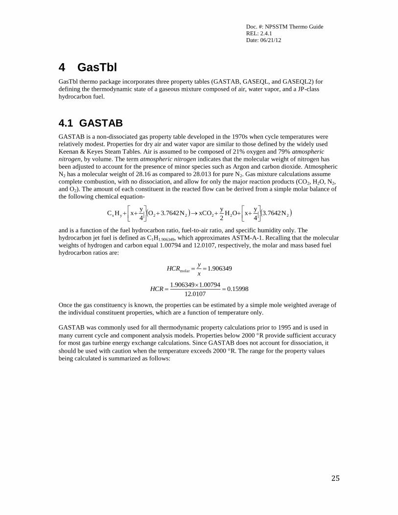
4 GasTbl GasTbl thermo package incorporates three property tables (GASTAB, GASEQL, and GASEQL2) for
defining the thermodynamic state of a gaseous mixture composed of air, water vapor, and a JP-class
hydrocarbon fuel.
4.1 GASTAB
GASTAB is a non-dissociated gas property table developed in the 1970s when cycle temperatures were
relatively modest. Properties for dry air and water vapor are similar to those defined by the widely used
Keenan & Keyes Steam Tables. Air is assumed to be composed of 21% oxygen and 79% atmospheric
nitrogen, by volume. The term atmospheric nitrogen indicates that the molecular weight of nitrogen has
been adjusted to account for the presence of minor species such as Argon and carbon dioxide. Atmospheric
N2 has a molecular weight of 28.16 as compared to 28.013 for pure N2. Gas mixture calculations assume
complete combustion, with no dissociation, and allow for only the major reaction products (CO2, H2O, N2,
and O2). The amount of each constituent in the reacted flow can be derived from a simple molar balance of
the following chemical equation-
22222yx N3.76424
yxOH
2
yxCON3.7642O
4
yxHC
and is a function of the fuel hydrocarbon ratio, fuel-to-air ratio, and specific humidity only. The
hydrocarbon jet fuel is defined as C1H1.906349, which approximates ASTM-A-1. Recalling that the molecular
weights of hydrogen and carbon equal 1.00794 and 12.0107, respectively, the molar and mass based fuel
hydrocarbon ratios are:
906349.1molar x
yHCR
15998.00107.12
00794.1906349.1
HCR
Once the gas constituency is known, the properties can be estimated by a simple mole weighted average of
the individual constituent properties, which are a function of temperature only.
GASTAB was commonly used for all thermodynamic property calculations prior to 1995 and is used in
many current cycle and component analysis models. Properties below 2000 R provide sufficient accuracy
for most gas turbine energy exchange calculations. Since GASTAB does not account for dissociation, it
should be used with caution when the temperature exceeds 2000 R. The range for the property values
being calculated is summarized as follows:
Doc. #: NPSSTM Thermo Guide
REL: 2.4.1
Date: 06/21/12
26
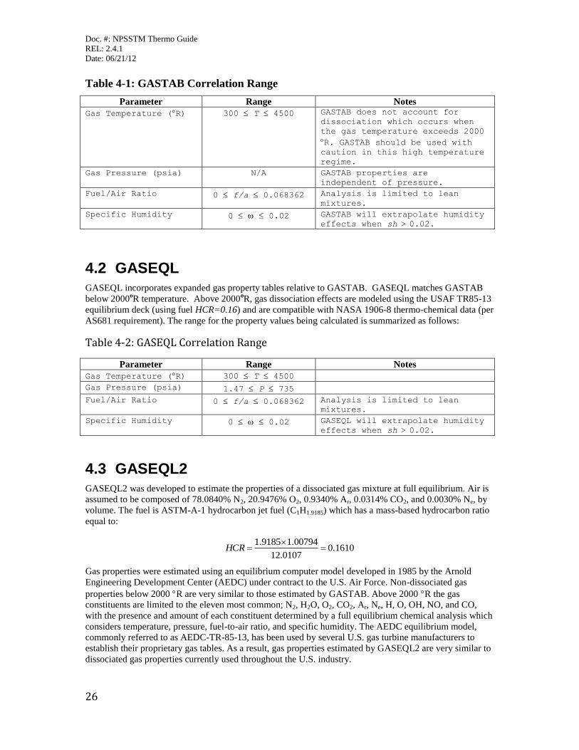
Table 4-1: GASTAB Correlation Range
Parameter Range Notes
Gas Temperature (R) 300 T 4500 GASTAB does not account for
dissociation which occurs when
the gas temperature exceeds 2000
R. GASTAB should be used with caution in this high temperature
regime.
Gas Pressure (psia) N/A GASTAB properties are
independent of pressure.
Fuel/Air Ratio 0 f/a 0.068362 Analysis is limited to lean
mixtures.
Specific Humidity 0 0.02 GASTAB will extrapolate humidity
effects when sh > 0.02.
4.2 GASEQL
GASEQL incorporates expanded gas property tables relative to GASTAB. GASEQL matches GASTAB
below 2000oR temperature. Above 2000
oR, gas dissociation effects are modeled using the USAF TR85-13
equilibrium deck (using fuel HCR=0.16) and are compatible with NASA 1906-8 thermo-chemical data (per
AS681 requirement). The range for the property values being calculated is summarized as follows:
Table 4-2: GASEQL Correlation Range
Parameter Range Notes
Gas Temperature (R) 300 T 4500
Gas Pressure (psia) 1.47 P 735
Fuel/Air Ratio 0 f/a 0.068362 Analysis is limited to lean
mixtures.
Specific Humidity 0 0.02 GASEQL will extrapolate humidity
effects when sh > 0.02.
4.3 GASEQL2
GASEQL2 was developed to estimate the properties of a dissociated gas mixture at full equilibrium. Air is
assumed to be composed of 78.0840% N2, 20.9476% O2, 0.9340% Ar, 0.0314% CO2, and 0.0030% Ne, by
volume. The fuel is ASTM-A-1 hydrocarbon jet fuel (C1H1.9185) which has a mass-based hydrocarbon ratio
equal to:
1610.00107.12
00794.19185.1
HCR
Gas properties were estimated using an equilibrium computer model developed in 1985 by the Arnold
Engineering Development Center (AEDC) under contract to the U.S. Air Force. Non-dissociated gas
properties below 2000 R are very similar to those estimated by GASTAB. Above 2000 R the gas
constituents are limited to the eleven most common; N2, H2O, O2, CO2, Ar, Ne, H, O, OH, NO, and CO,
with the presence and amount of each constituent determined by a full equilibrium chemical analysis which
considers temperature, pressure, fuel-to-air ratio, and specific humidity. The AEDC equilibrium model,
commonly referred to as AEDC-TR-85-13, has been used by several U.S. gas turbine manufacturers to
establish their proprietary gas tables. As a result, gas properties estimated by GASEQL2 are very similar to
dissociated gas properties currently used throughout the U.S. industry.
Doc. #: NPSSTM Thermo Guide
REL: 2.4.1
Date: 06/21/12
27
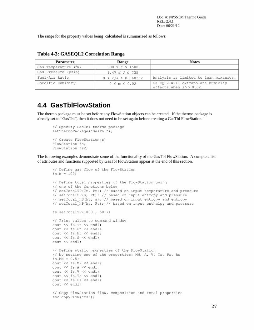
The range for the property values being calculated is summarized as follows:
Table 4-3: GASEQL2 Correlation Range
Parameter Range Notes
Gas Temperature (R) 300 T 4500
Gas Pressure (psia) 1.47 P 735
Fuel/Air Ratio 0 f/a 0.068362 Analysis is limited to lean mixtures.
Specific Humidity 0 0.02 GASEQL2 will extrapolate humidity
effects when sh > 0.02.
4.4 GasTblFlowStation
The thermo package must be set before any FlowStation objects can be created. If the thermo package is
already set to “GasTbl”, then it does not need to be set again before creating a GasTbl FlowStation.
// Specify GasTbl thermo package
setThermoPackage("GasTbl");
// Create FlowStation(s)
FlowStation fs;
FlowStation fs2;
The following examples demonstrate some of the functionality of the GasTbl FlowStation. A complete list
of attributes and functions supported by GasTbl FlowStation appear at the end of this section.
// Define gas flow of the FlowStation
fs.W = 100;
// Define total properties of the FlowStation using
// one of the functions below
// setTotalTP(Tt, Pt); // based on input temperature and pressure
// setTotalSP(s, Pt); // based on input entropy and pressure
// setTotal_hS(ht, s); // based on input entropy and entropy
// setTotal_hP(ht, Pt); // based on input enthalpy and pressure
fs.setTotalTP(1000., 50.);
// Print values to command window
cout << fs.Tt << endl;
cout << fs.Pt << endl;
cout << fs.ht << endl;
cout << fs.S << endl;
cout << endl;
// Define static properties of the FlowStation
// by setting one of the properties: MN, A, V, Ts, Ps, hs
fs.MN = 0.5;
cout << fs.MN << endl;
cout << fs.A << endl;
cout << fs.V << endl;
cout << fs.Ts << endl;
cout << fs.Ps << endl;
cout << endl;
// Copy FlowStation flow, composition and total properties
fs2.copyFlow("fs");

Doc. #: NPSSTM Thermo Guide
REL: 2.4.1
Date: 06/21/12
28
cout << fs2.W << endl;
cout << fs2.Tt << endl;
cout << fs2.Pt << endl;
cout << endl;
// Combine two FlowStations: flow, composition, ht and Tt are
// calculated, while Pt is carried over from the 1st FlowStation
fs.add("fs2");
cout << fs.W << endl;
cout << fs.Tt << endl;
cout << fs.Pt << endl;
cout << endl;
// Create FuelStation
FuelStation fus;
// Define fuel flow of the FuelStation
fus.Wfuel = 5;
// Burn FuelStation fuel in the FlowStation
// (use default fuel station settings)
// (use ideal efficiency for the purpose of the example)
fs.burn("fus",1);
cout << fs.W << endl;
cout << fs.FAR << endl;
cout << fs.ht << endl;
cout << fs.Tt << endl;
cout << endl;
Note that currently setting WAR of GasTbl FlowStation resets FAR to 0. While in the future this behavior
may be changed, for the time being, it is important to note that the original FAR value must be stored
before setting WAR and then must be reset after WAR has been assigned.
// Define water-air ratio of the FlowStation
// (assume no flow and enthalpy change for the purpose of the
// example)
real FARsave = fs.FAR;
fs.WAR = 0.0002;
fs.FAR = FARsave;
cout << fs.FARsave << endl;
cout << fs.FAR << endl;
cout << fs.WAR << endl;
Users will typically start the fluid flow using the FlowStart element. Therefore, they will use the FlowStart
element to set the temperature, pressure, flow rate, and water-to-air ratio. See the FlowStart element
description for additional information.
// Instantiate a FlowStart element
Element FlowStart AirStart {
// Set temperature, pressure, flow rate, and WAR
Tt = 520;
Pt = 14.7;
W = 50.;
WAR = 0.01;
}

Doc. #: NPSSTM Thermo Guide
REL: 2.4.1
Date: 06/21/12
29
Table 4-4: GasTblFlowStation Supported Parameters
Name Units I/O Description A in2 I/O Physical cross sectional area. Can be used to
set static conditions.
Ades * in2 I Design physical cross sectional area. Can be
used to set static conditions.
Ae * in2 O Effective area [A * Cd * cos( swirl )]
Cd I Discharge coefficient
Cps Btu/(lbm*R) O Cp based on static conditions
Cpt Btu/(lbm*R) O Cp based on total conditions
Cvs Btu/(lbm*R) O Cv based on static conditions
Cvt Btu/(lbm*R) O Cv based on total conditions
FAR lbm/lbm I Fuel-to-air ratio (Wf/Wa)
FARst lbm/lbm O Stoichiometric Fuel to Air Ratio
fracAir * O Fraction of the flow that is air
fracBurned * O Fraction of the flow that is burned fuel relative
to the overall gas flow
fracUnburn * O Fraction of the flow that is unburned fuel
relative to the overall gas flow
gams O Gamma (specific heat ratio) based on static
conditions
gamt O Gamma (specific heat ratio) based on total
conditions
hs Btu/lbm I/O Enthalpy based on static conditions. Can be used
to set static conditions.
ht Btu/lbm O Enthalpy based on total conditions
iDescription I
ks Btu/(sec*ft*R) O Conductivity based on static conditions
kt Btu/(sec*ft*R) O Conductivity based on total conditions
MN I/O Mach number. Can be used to set static
conditions.
MNdes I Design Mach number. Can be used to set static
conditions.
mus lbm/(ft*sec) O Viscosity based on total conditions
mut lbm/(ft*sec) O Viscosity based on total conditions
Prs O Prandtl number based on static conditions
Prt O Prandtl number based on total conditions
Ps psia O Static pressure
Pt psia O Total pressure
rhos lbm/ft3 O Density based on static conditions
rhot lbm/ft3 O Density based on total conditions
Rs Btu/(lbm*R) O Gas constant based on static conditions
Rt Btu/(lbm*R) O Gas constant based on total conditions
s Btu/(lbm*R) O Entropy
swirl rad I Swirl angle (relative to axial)
switchDes I Indicates if the flowstation is in design or off-
design mode
Ts R I/O Static temperature. Can be used to set static
conditions.
Tt R O Total temperature
us Btu/lbm O Internal energy based on static conditions
ut Btu/lbm O Internal energy based on total conditions
V ft/sec I/O Flow velocity. Can be used to set static
conditions.
W lbm/sec I Total Weight flow
Wa lbm/sec O Air flow
WAR lbm/lbm I Water-to-air ratio
Wc lbm/sec O Corrected weight flow. W*sqrt(theta)/delta
Doc. #: NPSSTM Thermo Guide
REL: 2.4.1
Date: 06/21/12
30
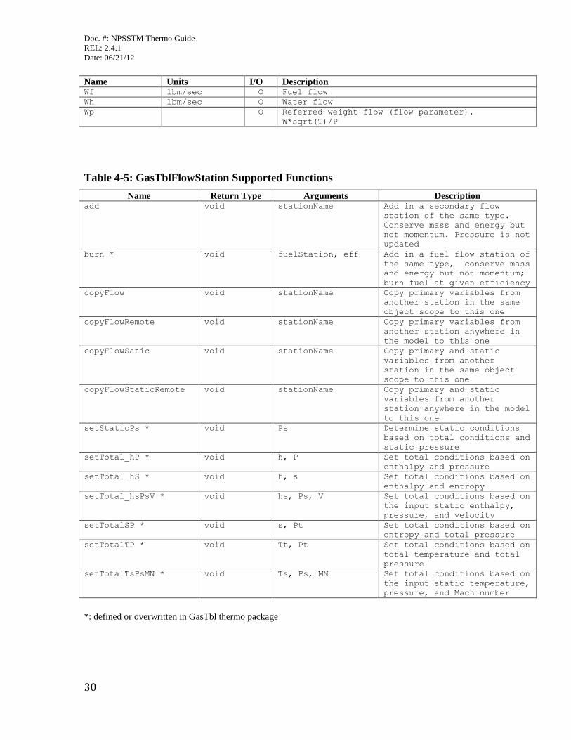
Name Units I/O Description Wf lbm/sec O Fuel flow
Wh lbm/sec O Water flow
Wp O Referred weight flow (flow parameter).
W*sqrt(T)/P
Table 4-5: GasTblFlowStation Supported Functions
Name Return Type Arguments Description add void stationName Add in a secondary flow
station of the same type.
Conserve mass and energy but
not momentum. Pressure is not
updated
burn * void fuelStation, eff Add in a fuel flow station of
the same type, conserve mass
and energy but not momentum;
burn fuel at given efficiency
copyFlow void stationName Copy primary variables from
another station in the same
object scope to this one
copyFlowRemote void stationName Copy primary variables from
another station anywhere in
the model to this one
copyFlowSatic void stationName Copy primary and static
variables from another
station in the same object
scope to this one
copyFlowStaticRemote void stationName Copy primary and static
variables from another
station anywhere in the model
to this one
setStaticPs * void Ps Determine static conditions
based on total conditions and
static pressure
setTotal_hP * void h, P Set total conditions based on
enthalpy and pressure
setTotal_hS * void h, s Set total conditions based on
enthalpy and entropy
setTotal_hsPsV * void hs, Ps, V Set total conditions based on
the input static enthalpy,
pressure, and velocity
setTotalSP * void s, Pt Set total conditions based on
entropy and total pressure
setTotalTP * void Tt, Pt Set total conditions based on
total temperature and total
pressure
setTotalTsPsMN * void Ts, Ps, MN Set total conditions based on
the input static temperature,
pressure, and Mach number
*: defined or overwritten in GasTbl thermo package
Doc. #: NPSSTM Thermo Guide
REL: 2.4.1
Date: 06/21/12
31
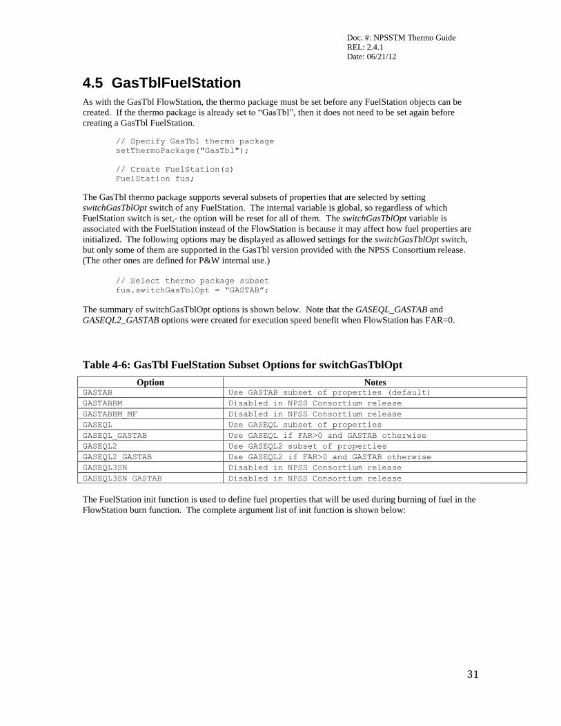
4.5 GasTblFuelStation As with the GasTbl FlowStation, the thermo package must be set before any FuelStation objects can be
created. If the thermo package is already set to “GasTbl”, then it does not need to be set again before
creating a GasTbl FuelStation.
// Specify GasTbl thermo package
setThermoPackage("GasTbl");
// Create FuelStation(s)
FuelStation fus;
The GasTbl thermo package supports several subsets of properties that are selected by setting
switchGasTblOpt switch of any FuelStation. The internal variable is global, so regardless of which
FuelStation switch is set,- the option will be reset for all of them. The switchGasTblOpt variable is
associated with the FuelStation instead of the FlowStation is because it may affect how fuel properties are
initialized. The following options may be displayed as allowed settings for the switchGasTblOpt switch,
but only some of them are supported in the GasTbl version provided with the NPSS Consortium release.
(The other ones are defined for P&W internal use.)
// Select thermo package subset
fus.switchGasTblOpt = “GASTAB”;
The summary of switchGasTblOpt options is shown below. Note that the GASEQL_GASTAB and
GASEQL2_GASTAB options were created for execution speed benefit when FlowStation has FAR=0.
Table 4-6: GasTbl FuelStation Subset Options for switchGasTblOpt
Option Notes GASTAB Use GASTAB subset of properties (default)
GASTABBM Disabled in NPSS Consortium release
GASTABBM_MF Disabled in NPSS Consortium release
GASEQL Use GASEQL subset of properties
GASEQL_GASTAB Use GASEQL if FAR>0 and GASTAB otherwise
GASEQL2 Use GASEQL2 subset of properties
GASEQL2_GASTAB Use GASEQL2 if FAR>0 and GASTAB otherwise
GASEQL3SN Disabled in NPSS Consortium release
GASEQL3SN_GASTAB Disabled in NPSS Consortium release
The FuelStation init function is used to define fuel properties that will be used during burning of fuel in the
FlowStation burn function. The complete argument list of init function is shown below:
Doc. #: NPSSTM Thermo Guide
REL: 2.4.1
Date: 06/21/12
32
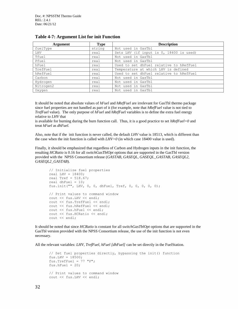
Table 4-7: Argument List for init Function
Argument Type Description fuelType string Not used in GasTbl
LHV real Sets LHV (if input is 0, 18400 is used)
Tfuel real Not used in GasTbl
Pfuel real Not used in GasTbl
hFuel real Used to set dhFuel relative to hRefFuel
TrefFuel real Temperature at which LHV is defined
hRefFuel real Used to set dhFuel relative to hRefFuel
Carbon real Not used in GasTbl
Hydrogen real Not used in GasTbl
Nitrogen2 real Not used in GasTbl
Oxygen real Not used in GasTbl
It should be noted that absolute values of hFuel and hRefFuel are irrelevant for GasTbl thermo package
since fuel properties are not handled as part of it (for example, note that hRefFuel value is not tied to
TrefFuel value). The only purpose of hFuel and hRefFuel variables is to define the extra fuel energy
relative to LHV that
is available for burning during the burn function call. Thus, it is a good practice to set hRefFuel=0 and
treat hFuel as dhFuel.
Also, note that if the init function is never called, the default LHV value is 18513, which is different than
the case when the init function is called with LHV=0 (in which case 18400 value is used).
Finally, it should be emphasized that regardless of Carbon and Hydrogen inputs in the init function, the
resulting HCRatio is 0.16 for all switchGasTblOpt options that are supported in the GasTbl version
provided with the NPSS Consortium release (GASTAB, GASEQL, GASEQL_GASTAB, GASEQL2,
GASEQL2_GASTAB).
// Initialize fuel properties
real LHV = 18400;
real Tref = 518.67;
real dhFuel = 10;
fus.init("", LHV, 0, 0, dhFuel, Tref, 0, 0, 0, 0, 0);
// Print values to command window
cout << fus.LHV << endl;
cout << fus.TrefFuel << endl;
cout << fus.hRefFuel << endl;
cout << fus.hFuel << endl;
cout << fus.HCRatio << endl;
cout << endl;
It should be noted that since HCRatio is constant for all switchGasTblOpt options that are supported in the
GasTbl version provided with the NPSS Consortium release, the use of the init function is not even
necessary.
All the relevant variables: LHV, TrefFuel, hFuel [dhFuel] can be set directly in the FuelStation.
// Set fuel properties directly, bypassing the init() function
fus.LHV = 18500;
fus.TrefFuel = 77 "F";
fus.hFuel = 20;
// Print values to command window
cout << fus.LHV << endl;
Doc. #: NPSSTM Thermo Guide
REL: 2.4.1
Date: 06/21/12
33
cout << fus.TrefFuel << endl;
cout << fus.hRefFuel << endl;
cout << fus.hFuel << endl;
cout << fus.HCRatio << endl;
cout << endl;
Users typically do not have to call the FuelStation init function directly because the FuelStation conditions
are set in the FuelStart element. See the FuelStart element description for further information.
// Instantiate a FuelStart element and set fuel parameters
Element FuelStart FusEng{
LHV_in = 18500;
Tref = 537;
hFuel = 20;
Wfuel = 5;
}
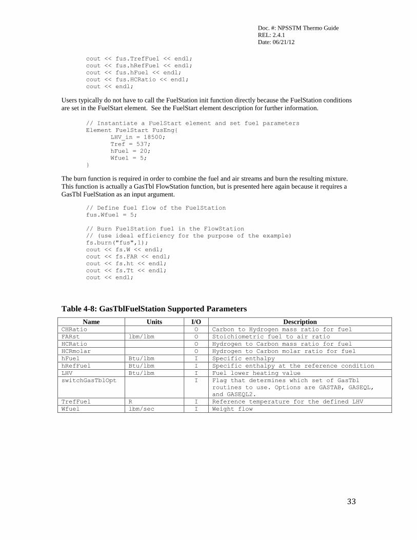
The burn function is required in order to combine the fuel and air streams and burn the resulting mixture.
This function is actually a GasTbl FlowStation function, but is presented here again because it requires a
GasTbl FuelStation as an input argument.
// Define fuel flow of the FuelStation
fus.Wfuel = 5;
// Burn FuelStation fuel in the FlowStation
// (use ideal efficiency for the purpose of the example)
fs.burn("fus",1);
cout << fs.W << endl;
cout << fs.FAR << endl;
cout << fs.ht << endl;
cout << fs.Tt << endl;
cout << endl;
Table 4-8: GasTblFuelStation Supported Parameters
Name Units I/O Description CHRatio O Carbon to Hydrogen mass ratio for fuel
FARst lbm/lbm O Stoichiometric fuel to air ratio
HCRatio O Hydrogen to Carbon mass ratio for fuel
HCRmolar O Hydrogen to Carbon molar ratio for fuel
hFuel Btu/lbm I Specific enthalpy
hRefFuel Btu/lbm I Specific enthalpy at the reference condition
LHV Btu/lbm I Fuel lower heating value
switchGasTblOpt I Flag that determines which set of GasTbl
routines to use. Options are GASTAB, GASEQL,
and GASEQL2.
TrefFuel R I Reference temperature for the defined LHV
Wfuel lbm/sec I Weight flow
Doc. #: NPSSTM Thermo Guide
REL: 2.4.1
Date: 06/21/12
34
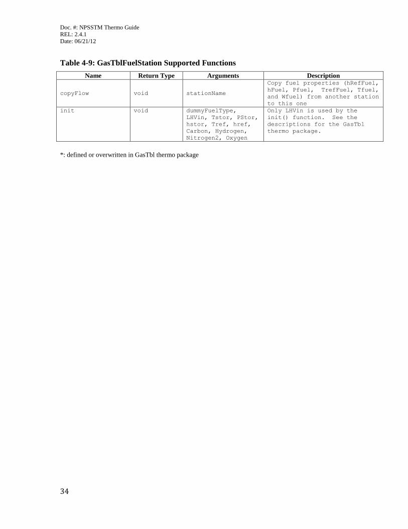
Table 4-9: GasTblFuelStation Supported Functions
Name Return Type Arguments Description
copyFlow void stationName
Copy fuel properties (hRefFuel,
hFuel, Pfuel, TrefFuel, Tfuel,
and Wfuel) from another station
to this one
init void dummyFuelType,
LHVin, Tstor, PStor,
hstor, Tref, href,
Carbon, Hydrogen,
Nitrogen2, Oxygen
Only LHVin is used by the
init() function. See the
descriptions for the GasTbl
thermo package.
*: defined or overwritten in GasTbl thermo package
Doc. #: NPSSTM Thermo Guide
REL: 2.4.1
Date: 06/21/12
35
5 Janaf Janaf is a program which calculates chemical equilibrium product concentrations made up of the following
seventeen reactants: H2O, CO2, O2, N2, AR, CH4O, NH3, H2, O,H,CO,OH,NO,N,CH4,C2H4,C10H8.
The Janaf thermodynamic package determines the equilibrium solution of mixtures typical for air
combusted with a hydrocarbon fuel. It is similar to CEA in that it solves for composition based on
minimization of Gibb’s free energy. But unlike CEA it does not have an unlimited number of products.
The product list has been cut down to those typically seen in hydrocarbon combustion. Cutting the product
list down enables the problem formulation to be simplified; reducing run time. Janaf models run much
quicker than CEA models!
Janaf allows the user to freeze the composition of the flow. When this is done, the static composition at a
given location is not recalculated. Instead, the upstream conditions are used.
Janaf does solve for fuel rich mixtures. The species C2H4 and C10H8 are used to represent unburned fuel.
5.1 JanafFlowStation
The thermo package must be set before any FlowStation objects can be created. If the thermo package is
already set to “Janaf”, then it does not need to be set again before creating a Janaf FlowStation.
// Specify Janaf thermo package
setThermoPackage("Janaf" );
// Create FlowStation
FlowStation fs;
With these two changes, the setThermoPackage and the fuel being defined correctly in the FuelStart, a
standard NPSS model that was running with a different thermo package should run with Janaf.
The FlowStation function setJanafComposition allows the user to set the fraction for each of the seventeen
possible reactants.
setJanafComposition( real q_h2o,
real q_co2,
real q_o2,
real q_n2,
real q_ar,
real q_ch4o,
real q_nh3,
real q_h2,
real q_o,
real q_h,
real q_co,
real q_oh,
real q_no,
real q_n,
real q_ch4,
real q_c2h4,
real q_c10h8 );
If the user wishes to set the flow composition to something other than the default, he/she would enter the
fractions of each constituent so that the total adds up to 1.0. The example below shows how to use the
Doc. #: NPSSTM Thermo Guide
REL: 2.4.1
Date: 06/21/12
36
setJanafComposition function. The default values have been used for this example. However, if the user
wishes to use the default settings, then this function does not need to be used.
// Set the flow station composition.
// The default values have been used for this example.
fs.setJanafComposition( 0.0, // H2O
0.000484, // CO2
0.231416, // O2
0.7555184, // N2
0.012916, // AR
0.0, // CH4O
0.0, // NH3
0.0, // H2
0.0, // O
0.0, // H
0.0, // CO
0.0, // OH
0.0, // NO
0.0, // N
0.0, // CH4
0.0, // CH4O
0.0); // C10H8
Attributes of the FlowStation have to be set prior to calculating the total conditions. Water-to-air (WAR)
ratio can be set as follows. Note that setting WAR will update the FlowStation composition accordingly.
// Set water-to-air ratio (specific humidity)
fs.WAR = 0.01;
Flow rate for a FlowStation can be set as follows.
// Set total flow rate, lbm/s
fs.W = 50.;
The total conditions at a station are set by any of the following setTotalxx functions.
// Define total properties of the FlowStation using
// one of the functions below
// setTotalTP(Tt, Pt); // based on input temperature and pressure
// setTotalSP(s, Pt); // based on input entropy and pressure
// setTotal_hS(ht, s); // based on input entropy and entropy
// setTotal_hP(ht, Pt); // based on input enthalpy and pressure
// set total state of fluid based on temperature and pressure
fs.setTotalTP(1000,50);
Once the flow rate and total conditions have been set, the static condition can be calculated by setting either
of the following: area (A), static enthalpy (hs), static pressure (Ps), static temperature (Ts), Velocity (V), or
Mach number (MN).
// Set Mach number. This will set the flow static conditions.
fs.MN = 0.5;
// Set duct area. This will set the flow static conditions.
fs.A = 200.;
Note that the last static property input sets the static conditions. The example above sets the Mach number
and then sets cross-sectional area. Because area is set last, the static conditions will be based on area and
the resulting Mach number will be calculated.
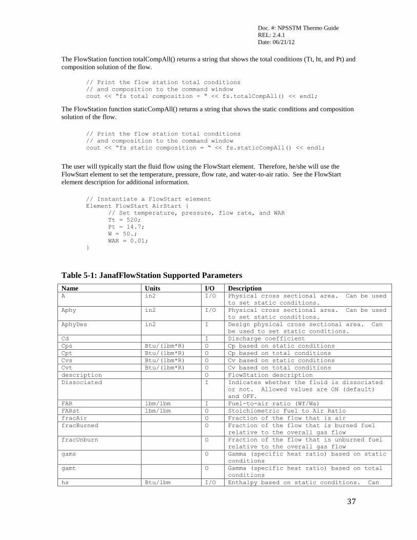
Doc. #: NPSSTM Thermo Guide
REL: 2.4.1
Date: 06/21/12
37
The FlowStation function totalCompAll() returns a string that shows the total conditions (Tt, ht, and Pt) and
composition solution of the flow.
// Print the flow station total conditions
// and composition to the command window
cout << “fs total composition = “ << fs.totalCompAll() << endl;
The FlowStation function staticCompAll() returns a string that shows the static conditions and composition
solution of the flow.
// Print the flow station total conditions
// and composition to the command window
cout << “fs static composition = “ << fs.staticCompAll() << endl;
The user will typically start the fluid flow using the FlowStart element. Therefore, he/she will use the
FlowStart element to set the temperature, pressure, flow rate, and water-to-air ratio. See the FlowStart
element description for additional information.
// Instantiate a FlowStart element
Element FlowStart AirStart {
// Set temperature, pressure, flow rate, and WAR
Tt = 520;
Pt = 14.7;
W = 50.;
WAR = 0.01;
}
Table 5-1: JanafFlowStation Supported Parameters
Name Units I/O Description A in2 I/O Physical cross sectional area. Can be used
to set static conditions.
Aphy in2 I/O Physical cross sectional area. Can be used
to set static conditions.
AphyDes in2 I Design physical cross sectional area. Can
be used to set static conditions.
Cd I Discharge coefficient
Cps Btu/(lbm*R) O Cp based on static conditions
Cpt Btu/(lbm*R) O Cp based on total conditions
Cvs Btu/(lbm*R) O Cv based on static conditions
Cvt Btu/(lbm*R) O Cv based on total conditions
description O FlowStation description
Dissociated I Indicates whether the fluid is dissociated
or not. Allowed values are ON (default)
and OFF.
FAR lbm/lbm I Fuel-to-air ratio (Wf/Wa)
FARst lbm/lbm O Stoichiometric Fuel to Air Ratio
fracAir O Fraction of the flow that is air
fracBurned O Fraction of the flow that is burned fuel
relative to the overall gas flow
fracUnburn O Fraction of the flow that is unburned fuel
relative to the overall gas flow
gams O Gamma (specific heat ratio) based on static
conditions
gamt O Gamma (specific heat ratio) based on total
conditions
hs Btu/lbm I/O Enthalpy based on static conditions. Can

Doc. #: NPSSTM Thermo Guide
REL: 2.4.1
Date: 06/21/12
38
Name Units I/O Description be used to set static conditions.
ht Btu/lbm O Enthalpy based on total conditions
iDescription I
imp lbf O Impulse
ks Btu/(sec*ft*R) O Conductivity based on static conditions
kt Btu/(sec*ft*R) O Conductivity based on total conditions
MN I/O Mach number. Can be used to set static
conditions.
MNdes I Design Mach number. Can be used to set
static conditions.
mus lbm/(ft*sec) O Viscosity based on static conditions
mut lbm/(ft*sec) O Viscosity based on total conditions
MW O Molecular weight
Pratio I Ratio of total pressure used to determine
static comp when staticComp is set to TOTAL
Prs O Prandtl number based on static conditions
Prt O Prandtl number based on total conditions
Ps psia O Static pressure
Pt psia O Total pressure
reconstitute I Determines if frozen or equilibrium
conditions are desired. Allow values are
EQUIL (default) or FROZEN.
rhos lbm/ft3 O Density based on static conditions
rhot lbm/ft3 O Density based on total conditions
Rs Btu/(lbm*R) O Gas constant based on static conditions
Rt Btu/(lbm*R) O Gas constant based on total conditions
s Btu/(lbm*R) O Entropy
staticComp I Allowed values are TOTAL (default), STATIC,
and SEPARATE
superOrSub I Determines if the subsonic or supersonic
static conditions are desired. Allowed
values are SUBSONIC (default) and
SUPERSONIC.
swirl rad I Swirl angle (relative to axial)
switchChokedMethod I Indicates the method used to determine the
statics when the flowstation is choked.
Allowed values are INVERT (default) and
HOLD. INVERT will decrease the area and
determine supersonic solution. HOLD will
set the static conditions to the choked
value.
switchDes I Indicates if the flowstation is in design
or off-design mode
switchFuelRich I Allowed values are OFF (default) and ON
Tratio I Ratio of total temperature used to
determine static comp when staticComp is
set to TOTAL
Ts R I/O Static temperature. Can be used to set
static conditions.
Tt R O Total temperature
us Btu/lbm O Internal energy based on static conditions
ut Btu/lbm O Internal energy based on total conditions
V ft/sec I/O Flow velocity. Can be used to set static
conditions.
W lbm/sec I Total Weight flow
Wa lbm/sec O Air flow
WAR lbm/lbm I Water-to-air ratio
Wc lbm/sec O Corrected weight flow. W*sqrt(theta)/delta
Wf lbm/sec O Fuel flow

Doc. #: NPSSTM Thermo Guide
REL: 2.4.1
Date: 06/21/12
39
Name Units I/O Description Wh lbm/sec O Water flow
Wp O Referred weight flow (flow parameter).
W*sqrt(T)/P
Table 5-2: JanafFlowStation Supported Functions
Name Return Type Arguments Description add void stationName Add in a secondary flow
station of the same type.
Conserve mass and energy but
not momentum. Pressure is not
updated
burn void fuelStation, eff Add in a fuel flow station of
the same type, conserve mass
and energy but not momentum;
burn fuel at given efficiency
copyFlow void stationName Copy primary variables from
another station in the same
object scope to this one
copyFlowRemote void stationName Copy primary variables from
another station anywhere in
the model to this one
copyFlowSatic void stationName Copy primary and static
variables from another
station in the same object
scope to this one
copyFlowStaticRemote void stationName Copy primary and static
variables from another
station anywhere in the model
to this one
getStationType string Returns FlowStation type
(e.g. “JanafFlowStation”)
setStaticPs void Ps Determine static conditions
based on total conditions and
static pressure
setTotal_hP void h, P Set total conditions based on
enthalpy and pressure
setTotal_hS void h, s Set total conditions based on
enthalpy and entropy
setTotalSP void s, Pt Set total conditions based on
entropy and total pressure
setTotalTP void Tt, Pt Set total conditions based on
total temperature and total
pressure
setTotalTsPsMN void Ts, Ps, MN Set total conditions based on
the input static temperature,
pressure, and Mach number
staticCompAll string Returns the static flow
conditions and composition
totalCompAll string Returns the total flow
conditions and composition
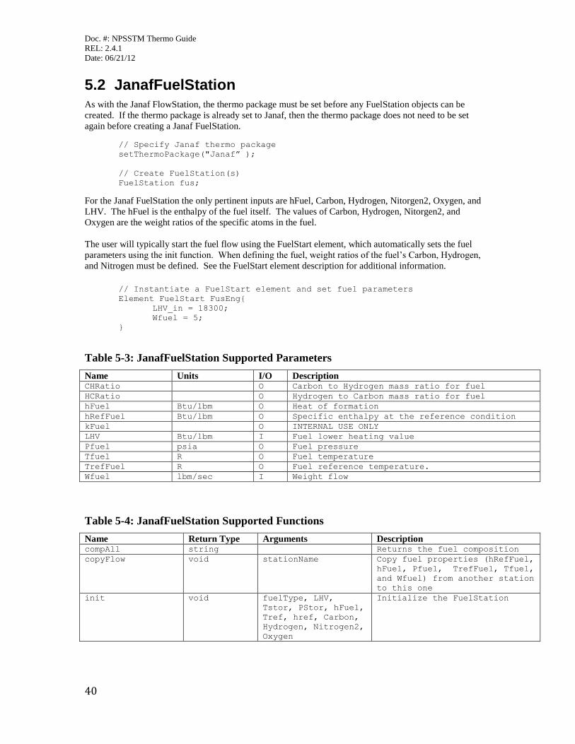
Doc. #: NPSSTM Thermo Guide
REL: 2.4.1
Date: 06/21/12
40
5.2 JanafFuelStation
As with the Janaf FlowStation, the thermo package must be set before any FuelStation objects can be
created. If the thermo package is already set to Janaf, then the thermo package does not need to be set
again before creating a Janaf FuelStation.
// Specify Janaf thermo package
setThermoPackage("Janaf” );
// Create FuelStation(s)
FuelStation fus;
For the Janaf FuelStation the only pertinent inputs are hFuel, Carbon, Hydrogen, Nitorgen2, Oxygen, and
LHV. The hFuel is the enthalpy of the fuel itself. The values of Carbon, Hydrogen, Nitorgen2, and
Oxygen are the weight ratios of the specific atoms in the fuel.
The user will typically start the fuel flow using the FuelStart element, which automatically sets the fuel
parameters using the init function. When defining the fuel, weight ratios of the fuel’s Carbon, Hydrogen,
and Nitrogen must be defined. See the FuelStart element description for additional information.
// Instantiate a FuelStart element and set fuel parameters
Element FuelStart FusEng{
LHV_in = 18300;
Wfuel = 5;
}
Table 5-3: JanafFuelStation Supported Parameters
Name Units I/O Description CHRatio O Carbon to Hydrogen mass ratio for fuel
HCRatio O Hydrogen to Carbon mass ratio for fuel
hFuel Btu/lbm O Heat of formation
hRefFuel Btu/lbm O Specific enthalpy at the reference condition
kFuel O INTERNAL USE ONLY
LHV Btu/lbm I Fuel lower heating value
Pfuel psia O Fuel pressure
Tfuel R O Fuel temperature
TrefFuel R O Fuel reference temperature.
Wfuel lbm/sec I Weight flow
Table 5-4: JanafFuelStation Supported Functions
Name Return Type Arguments Description compAll string Returns the fuel composition
copyFlow void stationName Copy fuel properties (hRefFuel,
hFuel, Pfuel, TrefFuel, Tfuel,
and Wfuel) from another station
to this one
init void fuelType, LHV,
Tstor, PStor, hFuel,
Tref, href, Carbon,
Hydrogen, Nitrogen2,
Oxygen
Initialize the FuelStation

Doc. #: NPSSTM Thermo Guide
REL: 2.4.1
Date: 06/21/12
41
Appendix: Revision Page
Rev Date Description of Change
– 07/2010 Initial release of this document. (NPSS Thermodynamic Property Package User Guide)
C1 09/2011 CRs incorporated for release of NPSS 2.4: CR311 (two new arguments -- trans.inp and thermo.inp files -- added to setThermoPackage() function when specifying CEA thermodynamic property package, 2.1, 2.2), CR326 (added further description
of the allFuelFlowStation fuel types, 1.1), CR293 (corrected several attribute names from uppercase to lowercase – Gams to gams,
Hs to hs, Mus to mus, Us to us, S to s, Kt to kt, Rhos to rhos, Swirl to swirl, Table 1-1 and Table 4-1)

Doc. #: NPSSTM Thermo Guide
REL: 2.4.1
Date: 06/21/12
42
NPSSTM Software © Copyright 2003. The U.S. Government, as Represented by the Administrator of the National
Aeronautics and Space Administration (NASA);
NPSSTM Software © Copyright 2008, 2009, 2010, 2011. The Ohio Aerospace Institute, on behalf of the
NPSSTM
Consortium. All rights reserved. Includes content licensed from the U.S. Government, National Aeronautics and
Space Administration under United States Copyright Registration Numbers V3503D364 and V3482D344.