numerical evaluation of contemporary excavator bucket
TRANSCRIPT
567
Jurnal Kejuruteraan 33(3) 2021: 579-591 https://doi.org/10.17576/jkukm-2021-33(3)-18
Numerical Evaluation of Contemporary Excavator Bucket Designs using Finite Element Analysis
Khurram Hameed Mughal* a, Salman Abubakar Bugvi a, Muhammad Asif Mahmood Qureshi b, Muhammad Aamir Khan a, Khazar Hayat a
a Department of Mechanical Engineering, Faculty of Engineering & Technology, The University of Lahore, Lahore, Pakistan. b Mechanical Engineering Department, Faculty of Engineering & Technology, University of Engineering and Technology, Lahore, Pakistan.
*Corresponding author:[email protected]
Received 8 July 2020, Received in revised form 06 October 2020 Accepted 10 November 2020, Available online 30 August 2021
ABSTRACT
Bucket is key and primary component of heavy construction machinery such as excavators. It has to bear high impact loads during digging process, resulting in large stress and deformations. This research work has been focused on reducing stress and deformations produced in excavator bucket due to digging. For this purpose, different design patents of excavator buckets (including ornamental designs) were considered. Various models of excavator buckets were developed by varying geometrical parameters such as number of blade teeth/tips and bucket curvature. Finite element analysis of these models was carried out by using ANSYS in order to determine stress and strains. Maximum values of Von Mises stress, principal stress, factor of safety and total deformation were evaluated numerically for all three-dimensional geometric models. Excavator bucket with least values of stress and deformations, but largest factor of safety, was identified through numerical computations. Mechanical performance of ornamental buckets having quarter circular curvature with 6 blade teeth was observed to be better as compared to designs having single blade strip or 5 blade teeth. Mass reduction up to 2.5%, while the stress reduction and factor of safety enhancement up to 9.6% was achieved by incorporating 6 blade teeth in ornamental design of excavator bucket.
Keywords: Blade teeth; deformation; Excavator Bucket; Finite Element Analysis; Ornamental Design; stress
INTRODUCTION
The industry of mining, forestry, and construction involves the function of digging and excavation. Over the past few decades, substantial investment and effort has been made in developing the mechanical solutions for undertaking these tasks (Patel & Prajapati 2011; Hadi et al. 2018). Modern machinery in the form of hydraulic excavators is greatly assisting these industries. The excavator is a versatile machine capable of working powerfully in open, rough and challenging environment, as well as operating in confined spaces smoothly. It provides a flexible solution for digging earthen material (Chen et al. 2018). The labor, time, effort, impact, and quality are all affected positively by the use of excavators. The productivity level has
multiplied through the use of these machines. The basic work principle steps of excavator are digging, elevation, swinging, and dumping the earthen material. The main frame rotates over rubber tires or crawlers through 360 degrees along a vertical axis. Other components of the excavator are the boom, arm, and bucket (Uzer 2008). The motion of each component is controlled through hydraulic actuators. Three-dimensional motion, stability, and the orientation of the excavator bucket can be controlled precisely through proper combination of actuators, mechanical links and joints.
The bucket digs into the ground with toothed edges. Bucket is the component that face direct loading and stress, thus failure occur usually in this component. The material composition, capacity, volume, and vibration absorption

580
capability are all important for bucket design to increase operating life and avoid sudden failure (Fernandez et al. 2001; Ladányi & Sümegi 2010; Fang et al. 2016). Bucket bears dynamic loading which is carried to the other components of excavator. Design of boom, arm, bucket, and other parts is therefore an important consideration. Excavator load carrying capacity may be increased by using special shaped buckets and suitable material (Fernandez et al. 2001; Ladányi & Sümegi 2010; Hadi et al. 2018). There is potential to explore new materials for bucket construction as well as optimizing the design of bucket to reduce weight, increase volume, and ability to withstand high stress occurring due to impact and repeated loadings. Aluminum has been suggested as an alternate to alloy steel bucket material. The stress and loading capacity of excavator arm has been evaluated for aluminum to increase the productivity per hour (Qi & Zhang 2014). Critical analysis of research by Solazzi has been undertaken, further clarifying concept of arm and bucket design optimization (Bosnjak 2011).
The rugged and rough operations of the excavator are correlated with the early failure of machine components. The operating style of machine as well as variation in suspended and impact load may affect the operating life of the machine. Other factors are the fragmentation and digging force required for the soil. The breakout force of the soil is critical as it impacts the bucket and the teeth assembly (Fang et al. 2016; Chen et al. 2018). Different soil material can be excavated through this machine. Soil may be soft, fragmented or muddy. The characteristics of soil material impact the bucket life. The excavator bucket has to be designed with adequate structural stability and strength such that it may be able to bear huge impact loading without causing early failure. Fatigue cracking is known to occur on leading face of bucket and upper face of boom. Severe damage can occur and the life of the components can only be a few months. The cracks developed due to impact loading may be minor in nature
but may propagate with the passage of time and cause early failure due to large stress concentration. Humidity, corrosion, heavy loads creating high stress, all contribute towards development of cracks in excavator components resulting in early failure (Boresi e& Schimdt 2003; Uzer 2008; Chen et al. 2018).
Performance analysis of excavator bucket has been done in past research, based on various loading conditions for safe design (Fernandez et al. 2001; Fang et al. 2016; Chen et al. 2018; Hadi et al. 2018). Research efforts have been made keeping in view the need to optimize excavator design and reduce stresses and failure rate of components. This will result in high loading capacity, reduced maintenance cost and better performance. The bucket should be able to withstand high impact loads with better capacity and long operating life at reasonable cost. Reduction in weight, material deformation and stress usually improves mechanical performance and operating life of excavator bucket. The addition of teeth, better volumetric capacity and enhanced factor of safety of bucket parts under full operating conditions are some of the desired options which can improve performance of excavators (Uzer 2008; Solazzi 2010; Patel & Prajapati 2011; Hadi et al. 2018).
A lot of work has been done on the analysis of excavator bucket using Finite Element Methods in order to test its performance and find suitable parameters of excavator boom, bucket and teeth (Bromfield & Evans 1988; Uzer 2008; Ladányi & Sümegi 2010; Patel & Prajapati 2011; Hadi et al. 2018; Suryo et al. 2018). Computer Aided Engineering (CAE) has been used extensively for this purpose. It improves calculation efficiency, reliability and performance (Lee & Han 2009; Hou et al. 2014). Stress, deformations, crack initiation and propagation, and the loads causing the failure of excavator components have been investigated using finite element analysis (Brinas et al. 2018). In order to cope with the rough working conditions, maximum working
FIGURE 1. Excavator bucket design patents a) Patent P1 with curvature C1 (Mc. Callelan et al. 2007), b) Patent P2 with curvature C2 (Boyapally et al. 2006), c) Patent P3 with curvature C3 (Albrecht 1984)

581
reliability has to be ensured for such mechanisms and machines (Bosnjak 2011). Various researches suggested new designs and modifications to reduce stress, deformations and cost, and increase working reliability of the excavator and its components. The trapezoidal design of the bucket has also been evaluated for stress concentrations identified in the teeth of the bucket model (Hadi et al. 2018). The variations in the design of the bucket teeth based on width, specific angles and materials have been analyzed through finite element analysis (Fernandez et al. 2001; Shaikh & Mulla 2015; Brinas et al. 2018; Hadi et al. 2018). A new tooth holder has also been proposed for excavator bucket in order to reduce stresses and increase operating life (Popescu et al 2018).
Simulation techniques have been followed by various researchers (Zhu et al. 2009; Patel & Prajapati 2011; Qi & Zhang 2014; Suryo et al. 2018) in typical applications such as mining and construction industry. Other methods have also been identified in order to optimize the design of excavator components and determination of stress developed as a result of applied loading. The structural characteristics of WK-20 bucket were analyzed through
FIGURE 2. CAD models of excavator buckets with 5 blades a) Bucket model 3 with 5 blade teeth on patent P1, b) Bucket model 4 with 5 blade teeth on patent P2, c) Bucket model 5 with 5 blade teeth on patent P3
FIGURE 3. CAD models of excavator buckets with 6 blades, a) Bucket model 6 with 6 blade teeth on patent P1, b) Bucket model 7 with 6 blade teeth on patent P2, c) Bucket model 8 with 6 blade teeth on patent P3
discrete element method (DEM). It is a theoretical and reliable method for the designing of bucket structure. Length to width ratio, bucket lip and front wall angle are key parameters to influence filling and load capacity of bucket (Hou et al. 2014).
Ornamental designs of excavator bucket and the effect of number of blade teeth on stress, deformations and natural frequency of bucket vibration have not been discussed yet in available literature. The main objective of this research effort is to evaluate various designs of excavator buckets and the stresses and deformations produced during the digging process. For this purpose, various bucket designs were considered; ornamental design being one of them, with different profiles (Figure 1). Geometric parameters such as bucket profile, curvature and number of blade teeth were varied and numerical computations were carried out for design evaluation. The FEM analysis technique in complement with CAD modeling and usage of ANSYS software has been implemented in order to evaluate the mechanical behavior of excavator bucket. Various excavator bucket designs were evaluated through finite element analysis by applying compressive force in the
582
horizontal direction created during the digging process. The finding of this research work would be useful in improving the mechanical behavior and operating life of excavator buckets, and thus heavy construction machinery.
METHODOLOGY
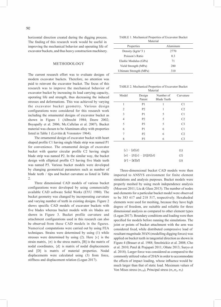
The current research effort was to evaluate designs of modern excavator buckets. Therefore, no attention was paid to reinvent the excavator bucket. The focus of this research was to improve the mechanical behavior of excavator bucket by increasing its load carrying capacity, operating life and strength, thus decreasing the induced stresses and deformations. This was achieved by varying the excavator bucket geometry. Various design configurations were considered for this research work including the ornamental designs of excavator bucket as shown in Figure 1 (Albrecht 1984; Deere 2002; Boyapally et al. 2006; Mc.Callelan et al. 2007). Bucket material was chosen to be Aluminum alloy with properties listed in Table 1 (Levitin & Voronstov 1964).
The ornamental design of excavator bucket with heart shaped profile C1 having single blade strip was named P1 for convenience. The ornamental design of excavator bucket with quarter circular profile C2 having single blade strip was named P2. In the similar way, the bucket design with elliptical profile C3 having five blade teeth was named P3. Various bucket models were developed by changing geometrical parameters such as number of blade teeth / tips and bucket curvature as listed in Table 2.
Three dimensional CAD models of various bucket configurations were developed by using commercially available CAD software Solid Works (EYU 1980). The bucket geometry was changed by incorporating curvature and varying number of teeth in existing designs. Figure 2 shows specific CAD models of excavator buckets with five blades whereas bucket models with six blades are shown in Figure 3. Bucket profile curvature and attachment configurations used in this research can also be observed from these CAD models in the figures. Numerical computations were carried out by using FEA techniques. Strains were determined by using (1) while stresses were determined by using (2). Here {ϵ} is the strain matrix, {σ} is the stress matrix, [B] is the matrix of nodal coordinates, {d} is matrix of nodal displacements and [D] is matrix of material properties. Nodal displacements were calculated using (3) from force, stiffness and displacement relation (Logan 2017).
TABLE 1. Mechanical Properties of Excavator Bucket Material
Properties AluminumDensity (kg⁄m^3 ) 2770Poisson’s Ratio 0.3
Elastic Modulus (GPa) 71Yield Strength (MPa) 280
Ultimate Strength (MPa) 310
TABLE 2. Mechanical Properties of Excavator Bucket Material
Model Design Patent
Number of Blade Teeth
Curvature
1 P1 1 C12 P2 1 C23 P1 5 C14 P2 5 C25 P3 5 C36 P1 6 C17 P2 6 C28 P3 6 C3
Three-dimensional bucket CAD models were then imported to ANSYS environment for finite element simulations and analysis purposes. Bucket models were properly meshed by using mesh independence analysis (Moaveni 2011; Liu & Glass 2013). The number of nodes and elements for a particular bucket model were observed to be 383 617 and 218 517, respectively. Hexahedral elements were used for meshing, because they have high degree of freedom, are suitable and reliable for three dimensional analysis as compared to other element types (Logan 2017). Boundary conditions and loading were then specified for models before running the simulations. The joint or points of bucket attachment with the arm was considered fixed, while distributed compressive load of resultant magnitude 30 kN (modelling digging forces) was applied on bucket teeth in tangential direction as shown in Figure 4 (Brauer et al. 1988; Smolnickiz et al. 2008; Cho et al. 2010; Patel & Prajapati 2011; Oñate 2013; Suryo et al. 2018). Larger force was considered as compared to the commonly utilized value of 20 kN in order to accommodate the effects of impact loading, whose influence would be much larger than that of static load. Maximum values of Von Mises stress (σVM), Principal stress (σ1,σ2, σ3)

583
and total deformation were evaluated numerically for all three dimensional geometric models of excavator bucket (Brauer et al. 1988; Li et al. 2006; Hein et al. 2008; Sfarni et al. 2009; Zhu et al. 2009; Cho et al. 2010; Logan 2011; Patel & Prajapati 2011). The simulation results were validated by using equations related to mechanics of materials. Equation (4) was used to calculate principal stresses for a particular state of stress (Boresi & Schimdt 2003).
FIGURE 4. Representation of Boundary Condition and Applied Loading on Excavator Bucket.
The solution of this equation gave values of three principal stresses. The three invariants I1, I2 and I3 involved in the equation were determined by using (5), (6) and (7).
After rigorous numerical computations, the performance of excavator bucket models was evaluated in terms of strength and operating life through critical data analysis. Modal analysis for each bucket geometry was also performed in order to identify the variation in bucket stiffness caused due to changes in bucket curvature and blade teeth. The modal analysis was carried out in order to determine the natural frequencies for various modes of bucket vibrations. The operating frequency of excavator components must be different than bucket natural frequencies in order to avoid resonance that results in
excessive stresses and deformations (Choi et al. 1997; Khoo et al. 2004; Logan 2011; Kelly 2012; Mughal et al. 2021). The Von Mises or equivalent stress was calculated from (8) after calculating principal stresses.
The factor of safety for excavator bucket designs was computed by using (9).
The model frequencies ω of excavator bucket vibrations can be computed numerically by using (10) after determining mass matrix [M].
RESULTS AND DISCUSSION
The current research was based on the comparative analysis of various profiles of excavator bucket. Finite element analysis was conducted on different bucket geometries for design assessment. The performance evaluation of bucket geometries was carried out on the basis of increased loading capacity and factor of safety but least stress, strains, and deformations. For specified loading conditions and material properties, Von Mises stress, principal stress and deformation were chosen to be the most important result parameters. Those bucket profiles were preferred which encountered least stress and deformations while having relatively high factor of safety, indicating enhanced loading capacity.
FIGURE 5. Von Mises Stress Contour plot for Bucket Model 6.

584
The simulation results indicate that the maximum Von Mises stress are 52 MPa and 33.4 MPa for excavator bucket models 1 and 2 respectively with single blade strip and occur near the joint / bucket attachment, while the stress is observed to be lower at other locations. For excavator bucket models with five blade teeth, such as model 3, 4 and 5, maximum Von Mises stress are computed to be 44.8 MPa, 29.8 MPa and 75 MPa, respectively. The Von Mises stress contour plot of specific excavator bucket model 6 (ornamental design P1 with six blade teeth) is illustrated in Figure 5. For this model, the maximum Von Mises or equivalent stress is 50.4 MPa and occurs near the joint / bucket attachment, while the stress is observed to be lower at other locations. For bucket model 7 (ornamental design P2 with six blade teeth / tips), equivalent stress is 26.9 MPa whereas for model 8, its maximum value is 75 MPa and occurs near the joint as expected. The yield strength σY of the bucket made of aluminum alloy is 280 MPa, therefore the excavator bucket is observed to be safe under these loading conditions. Maximum distortion energy / Von Mises criterion (σVM ≤ σY) was utilized in order to predict failure due to applied loading on excavator bucket.
FIGURE 6. Deformation contour plots for bucket models: (a) 1, (b) 2
The numerical computations of principal stresses indicate that the maximum normal stresses occur near the bucket joint with magnitude of 47.5 MPa and 15.7 MPa for excavator buckets 1 and 2, respectively. For excavator bucket models 3, 4 and 5, maximum tensile stresses are computed to be 41.4 MPa, 17.6 MPa and 73.6 MPa respectively. For bucket models 6, 7 and 8, maximum tensile stresses are 46.8 MPa, 18.1 MPa and 66.4 MPa
respectively. The stresses also have high magnitude at the locations of blade attachment with excavator bucket and near the point of application of load. However, all these stresses were observed to be lesser than the yield strength of the bucket material.
FIGURE 7. Comparison of deformation in excavator bucket models.
Another important aspect of bucket selection is the maximum deflection produced near the blade tips. The finite element simulations were utilized in order to compute the deformation produced in bucket measured with respect to Cartesian coordinates. The magnitude of deflection in the direction of applied load is greater as compared to other directions. However, total deformation was calculated numerically and results were represented in the form of contour plots as shown in Figure 6 for bucket models 1 and 2. It is observed from the numerical results that maximum deformation is produced at blade tips in all cases with magnitudes equal to 0.804 mm, 0.268 mm, 0.3829 mm and 0.3831 mm in models 1, 2, 4 and 7 respectively.
Some important structural results, such as Von Mises stress, maximum tensile stress, maximum compressive stress, maximum deformation and maximum shear stress, obtained through numerical computations, for better bucket geometries were recorded and analyzed carefully. The comparison of maximum deformation produced in blade tips of excavator buckets is shown in Figure 7, whereas the comparison of maximum stresses (Von Mises stress, tensile stress, compressive stress and shear stress) generated in various excavator buckets models is presented in Figure 8.
It is observed from the comparison of deformations in excavator bucket models that the maximum deformation is produced in model 8 with magnitude 3.42 mm, whereas least deformation is developed in model 2 with magnitude

585
0.268 mm. This indicates that model 2 (ornamental bucket design with quarter circular profile) has more stiffness as compared to other bucket geometries. The deformations found in ornamental bucket designs P1 and P2 are observed to be within acceptable limits.
FIGURE 9. Comparison of factor of safety in bucket models
The comparison of stresses in excavator bucket models indicate that the largest Von Mises, tensile and shear stresses are produced in models 5 and 8, while the maximum compressive stress is developed in model 1. Least tensile stress is produced in model 2, whereas least Von Mises, compressive and shear stresses are produced in model 7. This is due to the fact that model 7 with ornamental bucket design P2 having six blade teeth has greater surface area and moment of inertia within similar working space as compared to other bucket models according to theory of stress (Boresi & Schmidt 2003).
The factor of safety of each bucket model was calculated based on maximum Von Mises stress and yield strength of bucket material. The comparison of factor of safety for bucket models considered in this research is presented in Figure 9. Least factors of safety are observed in models 5 and 8 whereas largest factor of safety is
FIGURE 8. Comparison of maximum stresses in excavator bucket models.
observed in excavator bucket model 7. This indicates that model 7 will have more strength and working life as compared to other bucket models.
FIGURE 10. Variation of stresses with number of blade teeth for bucket design patent P1
After evaluating the mechanical performance of excavator bucket models, the influence of varying number of blade teeth on bucket designs were considered. For ornamental design of excavator bucket P1 with single blade strip, the stresses are reduced by incorporating five and six blade teeth respectively as illustrated in Figure 10. For ornamental design of excavator bucket P2, the stresses are

586
generally greater for single blade strip as compared to bucket designs with five and six blade teeth as shown in Figure 11. Generally, the stresses were observed to decrease with the increase of number of blade teeth as compared to single blade strip in excavator bucket designs. Increasing the number of blade teeth, the incision capability of the bucket would increase, making the digging process easier and reducing the stress induced. Further increase in number of blade teeth would reduce the strength, which is not recommended. Moreover, the pattern of variation of stresses in bucket design patents P1 and P2 was observed to be different, because of different bucket curvatures resulting in different moments of inertia.
Factor of safety for both design patents P1 and P2 is observed to increase by incorporating five and six blade teeth respectively, instead of single blade strip as illustrated in Figure 12. For design P2, factor of safety further enhances, but for design P1 it starts to decrease due to increase in Von Mises stress. Deformations in design patents P1 and P2 are observed to increase by incorporating five blade teeth. It was observed in bucket designs considered in this research that increasing number of blade teeth from five to six had no effect on total deformation, as shown in Figure 13. For excavator bucket design patent P3, significant variation in stresses were observed. However, the stresses were observed to be greater as compared to other bucket design patents.
Generally, stresses and deformations were observed to be lesser in excavator bucket design patent P2 as compared to that for design P1 and P3. On the other hand, the factor of safety for design patent P2 was found to be
FIGURE 11. Variation of stresses with number of blade teeth for bucket design patent P2
much better as compared to other bucket designs P1 and P3. All models considered in this research were observed to have factor of safety greater than three. It is important to note that the actual stress and deformation produced in excavator buckets in real scenario would be lesser as compared to the simulated values. It is due to the fact that the joint which is used to attach bucket with the arm was considered fixed, however it is actually revolute joint, which provides less constraining in stresses and deformations resulting from digging forces.
FIGURE 12. Variation of factor of safety with number of blade teeth for bucket design patents P1 and P2
It is observed from the numerical computations that, for a particular loading, least deformation and tensile stress are produced in bucket model 2 having a single blade strip. Least Von Mises stress, compressive stress and shear stress, and largest factor of safety are observed to be produced in model 7 with ornamental bucket design having six blade teeth. Ornamental design of excavator bucket P2 is found better as compared to other bucket designs, because it produces least stress and deformations at particular loading conditions. The quarter circular profile of this bucket design provides more material handling and load carrying capacity as compared to other designs. Mass reduction of 1.6% and factor of safety enhancement (stress reduction) of 16% were realized by incorporating five blade teeth in ornamental bucket design patent P1. Stress reduction and factor of safety enhancement of 9.6% with 2.5% mass reduction were achieved by incorporating six blade teeth in ornamental bucket design patent P2.
After conducting structural analysis of excavator bucket, modal analysis was performed in order to simulate the mode shapes and natural frequencies of bucket vibration. Modal analysis is performed in order to numerically compute the natural frequencies of vibrations

587
associated with different modes. The natural frequencies for first 5 modes of vibration for various bucket configurations are represented in Figure 14. These modes include twisting, bending, axial modes or their combination. For excavator buckets considered in this research, the first mode represents bending vibration about x axis. The second mode represents vertical vibration of the blade strip, while the third mode represents vertical vibrations of the bucket teeth. The fourth and nineth modes represent compound vibrations of bucket teeth along y axis and bucket side walls along z axis with different patterns. The fifth and sixth modes represent teeth bending about x axis with slightly different patterns while modes seven and eight represent the vibration of the blade teeth and lower portion of excavator bucket about z axis with different patterns.
The first modal frequency of bucket model 1 is found to be 39.63 Hz with amplitude of vibration equal to 0.087 m, while the second modal frequency is computed to be 69.6 Hz with vibration amplitude of 0.1 m.
First natural frequency of bucket model 1 is found to be the least as compared to multi blade buckets for both design patents P1 and P2. This is due to the fact that the mass of bucket with single blade is larger as compared to buckets having five and six blades, therefore natural frequency is least. It is observed that natural frequency of vibration changes by varying number of teeth.
The variation of natural frequency with number of blade teeth for bucket design patent P1 is illustrated in Figure 14, while the influence of changing number of blade teeth on modal frequencies for bucket design patent P2 is
FIGURE 13. Variation of maximum deformation with number of blade teeth for bucket design patents P1 & P2.
FIGURE 14. Comparison of modal frequencies in excavator bucket models.

588
illustrated in Figure 15. It was observed that the natural frequency for various modes of bucket vibration increased by increasing the number of blade teeth. However, this change in natural frequency was observed to be not much significant due to little variation in bucket mass and stiffness. The values of natural frequencies should be far
distinct from the forcing frequency (that may arise due to engine, digging process, and earthquake) in order to avoid resonance that may cause very large vibration amplitudes and stresses (Kelly 2012; Rao 2016; Mughal et al. 2021). The consolidated results showing the performance of all bucket designs used in this research are presented in Table 3.
FIGURE 15. Variation of modal frequency with number of blade teeth for bucket design patent P1
FIGURE 16. Variation of modal frequency with number of blade teeth for bucket design patent P2

589
TABLE 3. Consolidated Comparison of Excavator Bucket Design Patents
CONCLUSION
The current research was focused on the evaluation of different existing designs of excavator buckets and reduction of stress and deformations by varying the geometry. For this purpose, various designs including ornamental design of excavator bucket with single blade strip were considered, and variations were made in number of blade teeth and bucket curvature. Numerical computations were performed on all bucket models by using finite element techniques. All models were observed to perform better having factor of safety more than three for the specific loading condition.
1. The deformation and tensile stresses were observed tobe least in model 2 with ornamental bucket design P2having single blade strip. Von Mises stress, compressivestress and shear stress were found to be least in model 7with same bucket design having six blade teeth.
2. For ornamental design of bucket with heart shapedprofile, the stress and stiffness decreased gradually whenfive blade teeth (model 3) were incorporated instead ofsingle blade strip (model 1). This also caused increase inbucket factor of safety (up to 16%), strength and operating life with a mass reduction of 1.6%.
3. Incorporating six blade teeth in bucket design P1 (model 6) resulted in increase in stress and reduction in bucketstrength. Therefore, it would be better to incorporate fiveblade teeth instead of six and single blade strip in excavatorbucket with heart shaped curvature.
4. The variation of number of blade teeth on bucket design with elliptical profile was observed to have no significanteffect on bucket strength, stiffness and working life.
5. The modal frequencies were increased by incorporating more blade teeth in bucket designs, however that changewas observed to be less significant.
6. Ornamental design of excavator bucket P2 with quartercircular profile C2 was found better as compared to otherbucket designs, because of least stress and deformationsdue to specific loading. Its quarter circular curvature wouldprovide more material handling, load carrying capacity,operating life and strength as compared to other bucketdesigns
7. Excavator bucket model 7 with ornamental design P2,quarter circular curvature C2 and six blade teeth wasobserved to be better in terms of strength and operatinglife among all other bucket designs considered in thisresearch.
8. Incorporating six teeth in ornamental design of excavatorbucket with quarter circular profile would result in increasein strength, factor of safety and operating life (up to 9.6%) while reducing the stresses, with mass reduction of 2.5%,but would cause reduction in bucket stiffness (althoughlesser) as well.
In this research effort, fatigue loading was not considered along with dynamic behavior of the excavator bucket. Therefore, it is recommended that excavator bucket performance should be evaluated under repeated loading conditions as well.
DECLARATION OF COMPETING INTEREST
None.

590
REFERENCES
Albrecht, A. J. (1984). Bucket Design. U. S. P. D. Office. United States, J.I. Case Company, Racine, Wis. E02F 3/28: 7 Claims, 3 Drawing Sheets.
Boresi, A.P., Schimdt, R.J. (2003). Advanced Mechanics of Materials. New Jersey, USA, John Wiley and Sons,.
Bosnjak, S. M. (October 2011.). “ Comments on “Design of Aluminium Boom and Arm of Excavator.” Journal of Terramechanics: 459-462, .
Boyapally et al., (2006). Bucket. U. S. D. P. Office. United States, Caterpillar Inc, Peoria, US. US D524,826 S: 1 Claim, 8 Drawing Sheets.
Brauer, J.R., Zimmerlee, G.A., Bush, T.A., Sandel, R.J., and Schultz, R.D., (1988). “3D finite elementanalysis of automotive alternators under any load.”IEEE Transactions on Magnetics 24(1): 500-503.
Brinas, I.K.,Rebedea, N.I., and Oltean, I.L., (2018). “Bucket wheel excavator cutting tooth stress and deformation analysis during operation using Finite Elements Method (FEM).” Mining–Informatics, Automation and Electrical Engineering 56.
Bromfield, M.A., and Evans, W.T., (1988). “Computer modelling of microexcavator.” Computer-aided design 20(9): 549-554.
Chen, J., Zou, Z., and Pang, X., (2018). “Digging performance characterization for hydraulic excavator considering uncertainty during digging operation.” Proceedings of the Institution of Mechanical Engineers, Part C: Journal of Mechanical Engineering Science 232(5): 857-871.
Cho, S.S., Shin, C.S., Lee, C.S.,Chang, H., and Lee, K.W., (2010). “Assessment of an engine cylinderhead-block joint using finite element analysis.”International Journal of Automotive Technology11(1): 75-80.
Choi, K. K., Shim, I., and Wang, S., (1997). “Design sensitivity analysis of structure-induced noise and vibration.”
Deere, J., (2002). Bucket Tooth Catalogue, USA.Eyu, M. (1980). “CAD of Construction Machines.”
Mashinostroenie, Moscow.Fang, Z.Q., Hu, G.M., Gui, W.J., and Liu, Y., (2016).
Analysis of contact forces of particles with excavator bucket in digging process by using discrete element method. Mechanics and Mechanical Engineering: Proceedings of the 2015 International Conference (MME2015), World Scientific.
Fernandez, J.E.,Vijande, R. Tucho, R., Rodrı́guez, J., and Martı́n, A., (2001). “Materials selection to excavator teeth in mining industry.” Wear 250(1-12): 11-18.
Hadi, S., Andika, R.M., and Chamid, K., (2018). Design and analysis of trapezoidal bucket excavator for backhoe. SHS Web of Conferences, EDP Sciences.
Hein, C., Hong, S., Suh, J., Hoffmann, H., and Kim, N., (2008). “Finite element analysis of rotary blanking:
Effects of punch geometries on cutting area and stress distribution.” International Journal of Automotive Technology 9(2): 211-216..
Hou, Y. J., Li, A.F., Gao, S.H., and Wang, G.Q., (2014). Structural Analysis and Optimization of Mechanical Excavator WK-20 Bucket Based on Discrete Element Method. Applied Mechanics and Materials, Trans Tech Publ.
Kelly, S. G. (2012). Mechanical vibrations: theory and applications, Cengage learning Stamford, USA.
Khoo, L.M., Mantena, P.R., and Jadhav, P., (2004). “Structural damage assessment using vibration modal analysis.” Structural Health Monitoring 3(2): 177-194.
Ladányi, G. and Sümegi, I., (2010). “Bucket and Cutting Tooth Developments for the Bucket Wheel Excavators of Mátra Power Station LLC.” Annals of the University of Petroşani, Mechanical Engineering 12: 151-162.
Lee, D.C. and Han, C.S., (2009). “CAE (computer aided engineering) driven durability model verification for the automotive structure development.” Finite Elements in Analysis and Design 45(5): 324-332.
Levitin, B.S., Voronstov, G., (1964). “Usage of Aluminium Alloy in the metal structures of Cranes.” Mashinostroenie, Moscow.
Li, Y., Xu, X., and Qiu, Q., (2006). FEM-based structure optimization with grid-enabled analysis environment. 2006 6th World Congress on Intelligent Control and Automation, IEEE.
Liu, Y. and Glass, G., (2013). “Choose the best element size to yield accurate FEA results while reduce FE model’s complexity.” Br. J. Eng. Technol 1: 13-28.
Logan, D. L. (2017). A First Course in the Finite Element Method. Boston, USA, Cengage Learning.
Manisha P. Tupkar et al. (March 2015). “Design and Analysis of an Excavator Bucket.” International Journal of Scientific Research Engineering & Technology vol. 4(no. 3, ): 227-229,.
Mc. Callelan., et al., (2007). Excavator Bucket. U. S. D. Patent. United States, Caterpillar Inc. US D551,684 S: 1 Claim, 7 Drawing sheets.
Moaveni, S. (2011). Finite element analysis theory and application with ANSYS, 3/e, Pearson Education India.
Mughal, K. H., Qureshi, M. A. M., Qaiser, A. A., and Khalid, F.A., (2021). Numerical Evaluation of State of the Art Horn Designs for Ultrasonic Vibration Assisted Machining of Nomex Honeycomb Composite. Research Square. Preprint. DOI: 10.21203/rs.3.rs-207300/v1.
Mughal, K. H., Qureshi, M. A. M., and Raza, S. F. (2021). “Novel ultrasonic horn design for machining advanced brittle composites: A step forward towards green and sustainable manufacturing.” Environmental Technology & Innovation: 101652.

591
Oñate, E. (2013). Structural analysis with the finite element method. Linear statics: volume 2: beams, plates and shells, Springer Science & Business Media.
Patel, B. P. and Prajapati, J.M., (2011). “A review on FEA and optimization of backhoe attachment in hydraulic excavator.” International Journal of Engineering and Technology 3(5): 505.
Popescu, F.D., Radu, S.M., Andras, A., (2018). “Study of Functional Performance Improvement for Cutting Teeth Mounted on Bucket Wheel Excavator.” Mining-Informatics, Automation and Electrical Engineering(No. 3).
Qi, X.M., Zhang, J.D., (2014). “ANSYS Workbench for Static Analysis of Excavator Arm.” Advanced Materials Research: 926-930.
Sfarni, S., Bellenger, E., Fortin. J., and Malley, M., (2009). “Finite element analysis of automotive cushion discs.” Thin-Walled Structures 47(4): 474-483.
Shaikh, B. P., and Mulla, A.M., (2015). “Analysis of bucket teeth of backhoe excavator loader and its weight optimization.” International Journal of Engineering Research & Technology 4(5): 289-295.
Smolnicki, T., Derlukiewicz, D., and Stańco, M., (2008). “Evaluation of load distribution in the superstructure rotation joint of single-bucket caterpillar excavators.” Automation in Construction 17(3): 218-223.
Solazzi, L. (2010). “Design of an Aluminium Boom and Arm for an Excavator.” Journal of Terramechanics: 201-207.
Suryo, S. H., Bayuseno, A.P., Jamari, J., and Ramadhan, G., (2018). “Simulation of Excavator Bucket Pressuring Through Finite Element Method.” Civil Engineering Journal 4(3).
Uzer, C. C., (2008). Shape optimization of an excavator boom by using genetic algorithm.
Zhu, C.H., Guo, X.Y., and Wang, S.I., (2009). “Finite Element Analysis of Working Equipment of Excavator Based on Pro/E and ANSYS [J].” Coal Mine Machinery 4.