nuuasa - scalemates
TRANSCRIPT

ITEM 35134
BRITISH MAIN BATTLE TANKNuuasaThe first production Challengers were
:-r .•£•=•: :: r-e British Army early in 1983."F>ie> *ere buitt by the Royal Ordnance Fac-
. .^r-rCi - ,',est Yorkshire, England, and—•= >a e-cer is the latest in a long line of•a~-:-.s cante tanks produced in Leeds which
C'ude the Chieftain, Centurion and
•r '• e~a - ,vas designed by the Fighting• •?•• : es =esearch and Development Estab--~-~=r~. a:-' Known as the Military Vehicles
arc; Efxjineering Establishment) late in the; =.-; e^'e'ed service in 1967. More than
••:>'. ~- ;-a~s .-,ere built for the British Army:•:- =• -=-r:; ----.. the Vickers factory located-•—: E = .-. :• E-gia^d. Having cornpleted pro-
.. ... ;... . .,._ -a:i0rjes were kept
rijs. ••T zrx^ "^y~ overseas governments,
Iran alone ordering over 2,000 differentvariants, and Kuwait ordering 143. Since its in-troduction in 1967 the Chieftain has been keptup to date and continually modified to remainan effective weapons system.Project FV4030 (Chieftains for Iran) called for1,300 M.B.T.'s which were improved Chieftains.The Iranians had already been delivered 187FV4030/1 when the New Revolutionary Go-vernment cancelled all orders in February1979. FV4030/2, called the "Shir Iran 1", waswell advanced and over 100 of these M.B.T.'swere to be delivered to Iran in 1980. The muchimproved specifications included new enginesand gear boxes and much greater perform-
ance. When the order was cancelledthe tanks were modified and soldto the Jordanian government and
renamed 'The Khalid". Jordan received 278Khalids with deliveries beginning in 1980.The original Iranian order was to be in threephases and during 1977 seven prototypes ofthe FV4Q30/3 were produced. This variant,'The Shir Iran fl", used Chobham armour andhad a completefy re-designed hull and turret,and since much of the research and develop-ment plus tooling had been paid for by thelate Shah of Iran it seemed prudent to use thisas a basis for further development of a newM.BT. for the British Army during the 1980's.Originally, the successor to the Chieftain forthe British Army was to be developed jointlywith the government of West Germany, andwas known as the F.M.BT. (Future Main Bat-tle Tank).Because of the high expense involved and thediffering tank philosophies between the twocountries the plan was abandoned and replac-ed by the national M.B.T80 program, which inturn, because of expense, was terminated in1981. In July 1980 the British Minister forDefence stated in the House of Commons "Itis now clear that the M.B.T.80 cannot be avail-able until the early 1990's, and in order to meetthe threat a much earlier enhancement of
1/35 MILITARY MINIATURE SERES
irk
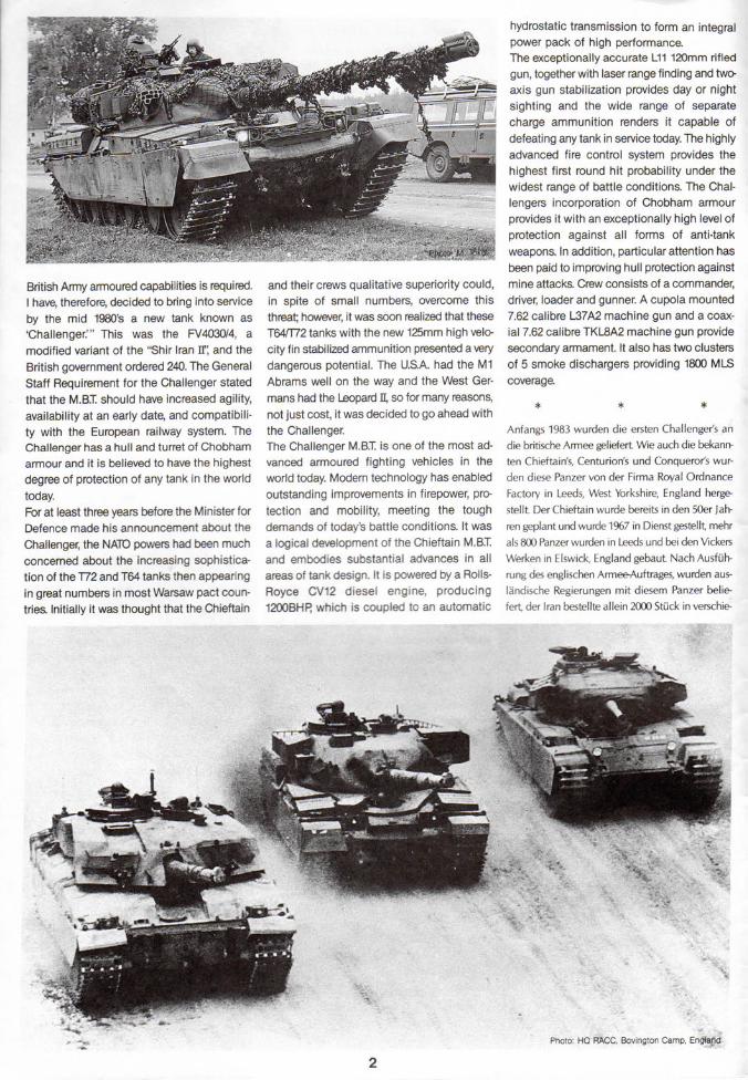
British Army armoured capabilities is required.I have, therefore, decided to bring into serviceby the mid 1980's a new tank known as'Challenger.'" This was the FV4030/4, amodified variant of the "Shir Iran IT, and theBritish government ordered 240. The GeneralStaff Requirement for the Challenger statedthat the M.B.T. should have increased agility,availability at an early date, and compatibili-ty with the European railway system. TheChallenger has a hull and turret of Chobhamarmour and it is believed to have the highestdegree of protection of any tank in the worldtoday.For at least three years before the Minister forDefence made his announcement about theChallenger, the NATO powers had been muchconcerned about the increasing sophistica-tion of the T72 and T64 tanks then appearingin great numbers in most Warsaw pact coun-tries. Initially it was thought that the Chieftain
and their crews qualitative superiority could,in spite of small numbers, overcome thisthreat; however, it was soon realized that theseT64/T72 tanks with the new 125mm high velo-city fin stabilized ammunition presented a verydangerous potential. The U.S.A. had the M1Abrams well on the way and the West Ger-mans had the Leopard fl, so for many reasons,not just cost, it was decided to go ahead withthe Challenger.The Challenger M.B.T. is one of the most ad-vanced armoured fighting vehicles in theworld today. Modern technology has enabledoutstanding improvements in firepower, pro-tection and mobility, meeting the toughdemands of today's battle conditions. It wasa logical development of the Chieftain M.B.T.and embodies substantial advances in allareas of tank design. It is powered by a Rolls-Royce CV12 diesel engine, producing1200BHR which is coupled to an automatic
hydrostatic transmission to form an integralpower pack of high performance.The exceptionally accurate L11 120mm rifledgun, together with laser range finding and two-axis gun stabilization provides day or nightsighting and the wide range of separatecharge ammunition renders it capable ofdefeating any tank in service today. The highlyadvanced fire control system provides thehighest first round hit probability under thewidest range of battle conditions. The Chal-lengers incorporation of Chobham armourprovides it with an exceptionally high level ofprotection against all forms of anti-tankweapons. In addition, particular attention hasbeen paid to improving hull protection againstmine attacks. Crew consists of a commander,driver, loader and gunner. A cupola mounted7.62 calibre L37A2 machine gun and a coax-ial 7.62 calibre TKL8A2 machine gun providesecondary armament. It also has two clustersof 5 smoke dischargers providing 1800 MLScoverage.
Anfangs 1983 wurden die ersten Challenger's an
die britische Armee geliefert Wie auch die bekann-
ten Chieftain's, Centurion's und Conqueror's wur-
den diese Panzer von der Firma Royal Ordnance
Factory in Leeds, West Yorkshire, England herge-
stellt Der Chieftain wurde bereits in den 50er Jah-
ren geplant und wurde 1967 in Dienst gestellt, mehr
als 800 Panzer wurden in Leeds und bei den Vickers
Werken in Elswick, England gebaut Nach Ausfiih-
rung des englischen Armee-Auftrages, wurden aus-
landische Regierungen mit diesem Panzer belie-
fert, der Iran bestellte allein 2000 Stuck in verschie-
Photo: HQ RACC, Bovington Camp, England

•
•US,
_4g RAfcC, Bovington CarflpvEnglarfd
-." -..-.-
rtiruar 1- •
imd 100 S
- - -
- . - -
- : - - . •
neue Motor. neue Getriebe L«
Leistung. Als der Viftrag annu
den die Panzer wiederum verbe
ranien verkauft Ab Anfang 198
iert wurde. wur-
ert und nach Jo-
erhiett Jocdanien
278 "The Khalid". Der ursprungliche iranische Auf-
trag war in drei Phasen und 1977 wurden sieben
Prototypen FV4030/3 gebaut Der Shir Iran n hat-
--- - ' - ----' - - ' - - - - - - : : -- .-
: andoen euopaechen Landem. her-
TIIL*IIII an den Kcsten und anderen Punkten
aJgimm gab der bndscne Verteidigungsmintster
•n July 1981 bekaratt. dass das Protekt 40304 ein
verfaesserter Shir ban E als Challenger mit 240 Ein-
hertEn. in die Produktion genommen wird Der
Challenger hat eine Wanne und einen Turm aus
Chobham-Panzerung und durfte einer der Panzer
sein, die am meisten Schutz der Besatzung geben.
Die Nato hatte in den letzten Jahren starke Be-
furchtung wegen der Uberlegenheit der T72 und
- : - L - - - : r: -.:-.--: =- J =.- :
T64 der Vkarschauer Pakt Staaten. die USA hat-
en den Abrams Ml. die Wesldeutschen den Leo-
pad 1 und so wude der Challenger als dringend
fur England benotigt
AngetneDen wad der Challenger mit etnem Rolls-
Itovce CV12 Diesel. 1200 PS automatisches Ce-
triebe Eine L11 Kanone mit 120 mm. Laser Ziel-
suchgerat und 2 Axial Kanooe fur Tag und Nacht-
einsatt Das ausserge\v6hnlich gute Feuerleitsysem
verspricht hochste Treffsicherheit in alien Kampfla-
gen. Die Besatzung besteht aus dem Kommandan-
ten, dem Fahrer, dem Schtitzen und dem Lade-
schutzen. Auf dem Turm ist ein 7,62 cal L37A2 M.G.
montiert und coaxial 7,62 cal TKL8A2 M.G. ist zu-
satzlich eingebaut, ausserdem sind noch zwei Wer-
fer fur je 5 Rauchraketen - zum eigenem Schutz
- vorhanden.
ITEM35134 1 35 MM-f-A-u>x>

Read before assemblyErst lesen — dann
* Study the instructions and photo-graphs before commencing assembly.*You will need a sharp knife, a screw-driver, a file and a pair of pliers.*Use cement sparingly. Use onlyenough to make a good bond.* Apply cement to both parts to be join-ed.* Make sure to ventilate room, when youuse cement and paints.A This mark denotes paint color, with^^ color names and numbers for TamiyaAcrylic Paints and Tamiya Paint Markers.Page 12 has detailed painting instructions;however, some parts should be paintedprior to model's completion, and these arecalled out during assembly.*Vor Beginn die Bauanleitung studierenund den Nummern nach die Elemente zu-sammenbauen.*Bauteile nicht vom Spritzl ing ab-brechen, vorsichtig abschneiden oder ab-zwicken*Teile vor Kleben zusammenhalten, aufgenauen Sitz achten. Nicht zuvielKlebstoff verwenden. Kleine Teile haltman mit Pinzette fest.*Abziehbilder vorsichtig von der Unter-lage im Wasser abschieben, auf richtigenSitz achten und gut trocknen lassen*Der Bastelraum sollte bei Verwendung vonFarben und Klebstoff gut geliiftet sein^fc Dieses Zeichen zeigt die Farbe und^^ Farbnummer der Tamiya Acrvl-
Farben und Paint Marker
UNUSED PARTSNICHT BENOTIGTE TEILE
One of each is not used, A1.A3, A6, A7, A9, A10, A26.Eines davon wird nicht benotigt
o WHEELSRADER
<«Road Wheels. *Make 12 sets.<^Laufrad^> *12 Satz machen
< Drive Sprocket s» * Make 2 sets.<gKettenantriebsrad£> *2 Satz machen
A41
A 40
AI8
Poly Cap (small) <Poly Cap (klein)
(Idler Wheels * Make 2 sets.^Spannrad> *2 Satz machen
A 33
Flat Black (XF-1)
A39
A38
Fbly Cap (small)Poly Cap (klein)
-^Support Rollers *Make 4 sets.•3Kettentragrolle> *4 Satz machen
A35
A34
Flat Black (XF-1)
A37
ASSEMBLY OF LOWER HULL 1WANNE 1
2mm x 15 Round Head Screw*Fix firmly.2mm*Fest a
A 23 *Cement firmly.*Fest zusammenkleben.
: 15 Rundfc
I NUT & SCREW SHOWN FULL SIZE' SCHRAUBE UND MUTTER IN
ORIGINALGROSSE
3D x 2
2mm x 15 Round Head Screw2mm x 15 Rundkopfschraube
x 2
2mm Nut2mm Mutter
CUTTING OFF PARTSDo not break parts away from sprue,but remove them carefully with a cuttingtool.
A24
2mm x 15 Round Head Screw —* Fix firmly.2mm x 15 Rundkopfschraube*Fest anziehen
ASSEMBLY OF LOWER HULL 2WANNE 2
Idler Wheel A 46* Press on.Spannrad*Aufpressen.
A 23 *Cement firmly.*Fest zusammenkleben.
Drive Sprocket* Press on.Kettenantriebsrad*Aufpressen.

> SG SUSPENSION ARMS^FHASGUNG
Road Wheel madein stepO-
^^^^^ // Laufrad (Siehe Step
TAMIYA
;• :ement wheels, justpan on.Oe Laufrader nicht ankleben,nr aufpressen.
GUN TRAVEL LOCK STAYROHRLAGERBOCK
f\G OF REAR PANEL\J MARKIERUNG DER HECKPLATTE
Refer below for marking of panel. Do thisbefore assembly.Vor Zusammenbau - unteres Bild studieren.
Flat Black (XF-1)
—Decal®or Decal®Decal ®Decal ®
B56
Flat Black (XF-1)
oB52
ATTACHING ROAD WHEELSEINBAU DER LAUFRADER
*Cement road wheelsand arms to hull start-ing at the back.*DieRadervom hinte-ren Wannenende hereinbauen
Lower HullWanne
Make sure that every wheelcontacts the ground.Jedes Rad muss auf dem Bodenauflieeen.
B53
B96
ASSEMBLY OF GUN TRAVEL LOCK STAYZUSAMMENBAU DES ROHRLAGERBOCKES
-B79
B95Tabs on B95 & Iface inward.
^Finishing Gun Travel Lock Stay>•^Endmontage des Rohrlagerbockes^
B89*Do not cement.*Nicht kleben
B81
Gun Travel Lock StayRohrlagerbock
ASSEMBLY OF REAR PANEL 1ZUSAMMENBAU DER HECKPLATTE
A15 BIOS A4
B97 A25ifGunMetal(X-10)
Flat Black (XF-1)
ITEM 35134

I TOW HOOKSCHLEPPHAKEN
B85 A 6 * Attach last.*Zuletzt anklebe
B82
B86
B83
JERRY CANKANISTER* Make 2 sets.*2 Satz machen
A27r Body Color
Fahrzeugfarbe
Body ColorFahrzeug-farbeA 32
Take a break, and let some fresh air inthe room!Etwas Pause und frische Luft in denRaum lassen, schadet nichts.
© TRANSPARENT PARTTRANSPARENTES TEIL
Cut out transparent part as shown.Wie gezeigt ausschneiden.
_*Cut out carefully./ *Sorgfa'ltig ausschneiden
HM- CHALLENGER
ASSEMBLY OF REAR PANEL 2HECKPLATTE
B91 B 100 Tow HookSchlepphaken
Be careful not to lose smallparts.Kleine Teile nicht verschlampen.
BI01
B84 A 42
B85/86 rest on A45's.*B85 + B86 liegt auf A45
•^Painting of A42§><Bemalung der Schlussleuchten^Body ColorFahrzeugfarbe A I 0
A 42
AH
ATTACHING REAR PANELANBAU DER HECKPLATTE
*Fix with cellophane tape untilcement has set.*Nachdem Kleben halt man Teilmit Tesafilm zum Trockenzusammen
Jerry Can* Do not cement.
Kanister* Nicht kleben
Rear Panel* Cement firmly:Heckplatte*Fest ankleben
ATTACHING INSIDE PARTS OF UPPER HULLINNENTEILE DER OBEREN WANNE
Transparent Part B*Cement.Transpare*Kleben
B68. Teii
B49

~OL CASE•••iRkZEUGKASTEN
B99
-- '.- NG OF A19KVALUNC VON A19
- i-ai
• White (X-2)
ATTACHING RIGHT SIDE PARTSTEILE DER RECHTEN SEITE
TAMIYA
•- I ATTACHING LEFT SIDE PARTS OF UPPER HULL- ' WANNENOBERTEIL LINKE SEITE
B43 A1 A19Tool Case B35
iWerkzeugkasten
A 1 9 fFlat Black (XF-1) A 2Apply to both sides.
ATTACHING RIGHT SIDE PARTS OFUPPER HULLWANNENOBERTEIL RECHTE SEITE
A 47 Gun Metal (X-10)
Fix tools in their pro-per places.Das Werkzeug an dierichtige Stelle.
ATTACHING HEAD LIGHTSSCHEINWERFER
a-e your time adding the front
Flat Black (XF-1)*r it
A26 B37 A29 A14 A13Flat Black
(XF-1)
A 16
B36*Body Color FahrzeugfarbeHandle Stie!Khaki (XF-49)
B59
ATTACHING FRONT PARTSEINBAU DER FRONTTEILE
fiBody ColorHandle StielKhaki (XF49) •^Painting & marking of A16
<«Bemalung A
A 47 G"n Metal (X-10)
Flat Green (XF.5):2White (X-2):1
Body ColorFahrzeugfarbe
B58
B54
A12 A 2 1
ITEM 35134

MAIN GUNKASOSESROHR ASSEMBLY OF LOWER TURRET
ZUSAMMENBAU TURMUNTERTE1L
B63
Semi Gloss Black (X-18) Khaki p<F-49) Semi Gloss Body Color Semi Gloss Black (X-18)
NUT & SCREW SHOWN FULL SIZE
SCHRAUBE UNO MUTTER INORICINALCROSSE
Black (X-18) ! Fahrzeugfarbe
*Add B25 & B26 first then B88,
3mm x 20 Round Head Screw 3mm Nut3mm x 20 Rundkopfschraube 3mm Mutter
© ATTACHING PERISCOPEEINBAU DES SEHROHRES
Attach B98 and Transparent Part A by turn-ing over upper turret.Einbau B98 und Transparent Teil A bei umge-drehten Turmteile.
Cement Transparent Part A.Transparentes Teil A kieben
»Clear Blue (X-23)
B98
B26
B88
The main gun is secured byscrew & nut. Tighten firmly.Das Kanonnenrohr wird mitSchraube und Mutter gesichert
utter fest anziehen.
Semi Gloss Black (X-18)
3mm x 20 Round Heaa3mm x 20 Rundk Main Gun
Kanonenroh
3mm Nut3mm Mutte.
C2 B57
B25
ATTACHING UPPER TURRETZUSAMMENBAU DES OBEREN TURMTEILES
*Make sure the edges matchproperly.*Auf genaue Passform derKanten achten
Bl2
C3*Fix with cello-phane tape until ce-ment has set.*Nach dem Kiebenhalt man Teil mitTesafilm zum Trockenzusammen.
B80Body ColorFahrzeugfarbe B I 3
Inside of upper turretInnenseite des Turmes
SMOKE DISCHARGERNEBELWERFER
*Make 2 sets.*2 Satz machen.
A 36
A 30
Body ColorFahrzeugfarbe
Flat Black (XF-1)
PAINTING & MARKING OF B73BEMALUNG UND MARKIERUNG VON 873
Decal ® Decal ©Gold Leaf (X-12) Abziehbild Abziehbild
r*• Body ColorIH Fahrzeugfarbe
Flat Green (XF-5):2 + White (X-2):1
TAMIYA COLOR CATALOGUEThe latest in cars, boats, tanks and ships.Motorized, radio controlled and museumquality models are all shown in full color inTamiya's latest catalogue. At your nearesthobby supply house.
B32
* Cut away. Lower Hull Transparent Part A B 98*Abschneiden Tumi - Unterteil Transparentes Teil A *Refer to left fiaure
&, *Siehe Bild links.Clear Blue (X-23)
ATTACHING TURRET SIDE PANELSTURM - SEITENTEILE
Note: A28s mount parallel B 72to each other.
B51 A8
SmokeDischargerNebelwerfe B73
*Refer to left figurefor painting &marking.* Bemalung sieheBild links.
Smoke DischargerNebelwerfer
8
B78

1 -RIMMING OF MESHF ZLSCHNEIDEN DER DRAHTGITTER
~iesh as shown below. Note mesh
••.g.tter wie unten gezeigt, zuschneiden.
. ','esh A*. (Full size)(3-ahtgitter A> ^fffr^ (Voile Crosse)
<Mesh B»>< Drahtgitter B»>
<sMesh C>><« Drahtgitter O
Refer to the figure above and trimmesh with a pair of scissors.Siehe Bilder oben. Drahtgitter mitSchere zuschneiden.
CAMOUFLAGE NET BIN7ARNNETZ-KORB
© LOADER'S HATCHL4DESCHUTZEN-KLAPPE
,Vier making the loader's hatch operable,sc'-t 366 as shown below.
- - _ . - • : - . - - : j - -Klaope zum otfnen sein- : • - • - :!er '-':te durchschneiden.
*Cut here*Hier durchschneiden
B66
Flat Green (XF5):2White (X-2):1
TAMIYATURRET PARTSTURMTEILE
Flat Black (XF-1)
- A 43
« Turret Part A•^Turmteil
—B30
•*Turret Part Cs><gTurmteil C>
B27
tTurret Part D*.^Turmteil Ds>
B28
B22
B21 B24
ASSEMBLY OF CAMOUFLAGE NET BINZUSAMMENBAU DES TARNNETZ-KORBES
BIO Body ColorFahrzeugfarbe
Mesh C -Drahtgitter C
^Attaching Mesh>•^Einbau der Drahtgitter^.*Cement trimmed mesh referring tofigure below.*Zugeschnittene Drahtgitter wie unten ge-zeiet ankleben.
*Apply cement to theframe.*Klebstoff auf denRahmen auftragen.
B2
ATTACHING UPPER LEFT SIDE PARTS OF TURRETEINBAU DER LINKEN TURMTEILE
A 22
B61
Body ColorFahrzeugfarbe
Mesh B Mesh ADrahtgitter B Drahtgitter A
*Can be made operable.*Kann auch zum offnen gebaut werden
B66A 4^ Flat Black (XF-1)
r
Turret Part CTurmteil C
Camouflage Net BinTarnnetz-Korb
ITEM 35134

PERISCOPESEHROHR
Transparent Part D*Cement.Transparentes Teil D*Kleben.
Body ColorFahrzeugfarbe
B17
SELECT PERISCOPE COVER IN CLOSEDOR OPEN POSITIONSEHROHR-DECKEL OFFEN ODER CE-SCHLOSSEN, AUSWAHLEN.
ATTACHING RIGHT SIDE PARTS OF TURRETEINBAU DER RECHTEN TURMTEILE
B77 B20
B75
Royal Blue (X-3)
B29The periscope cover can beselected open or closed.Der Sehrohr-Deckel kann offen odergeschlossen eingebaut werden.
ASSEMBLY OF CUPOLATURMKOPPEL - TEILE
I * Do not cement.*Nicht kleben
B55 B65 B19 PeriscopeSehror
TRACK CONSTRUCTIONKETTENMONTACE
1. Melt pin head carefully with aheated screwdriver etc.1 Zapfenkopf mit heissen Schrauben-zieher verschmelzen
-BIS B67* Select either openor closed.*Gesdoffen a
B76 Body Color
chlossen od
^^Fahrzeugfarbe
Q ^ White (X-:
GunB74
2. Immediately press pinheads with your finger.2. Sofort Zapfenpressen.
If track is broken, strengthen with staplesor thread.Bei Kettenbruch mit Heftklammern oder Drahtflicker,
Staple hereHier mit Draht heften
J\l
ATTACHING UPPER HULLEINBAU DES WANSEN-OBERTEILE S
* Select eftner openQ 4 Of closed B46
*Note direction of tracks.*Auf Richtung der Kette achten
10

TAMIYACOMMANDERKOMMANDANT f Model is now complete. Finish it
by painting and adding markings.Mode! I ist jetzt fertig. Be-malen und Abziehbilde
\anbringen.
ATTACHING TURRETEINSETZEN DES TURMES
—^T Flat Black(XF1)
h Khaki (XF-49):2 4Olive Drab (XF-62M
NUMBER PLATE
Slit about 3mm as shown below andbend.NUMMERN PLATTECa 3mm einschneiden und umbiegen.
-Transparent Part CTramparentes Teil C
THE MATCHING OF VEHICLE SERIALNUMBER & DIVISION ASSIGNEDFMHRZEUC SERIEN NUMMER UNDDIVISIONS-ZEICHEN
<iGun Travel Lock»>"«Rohrlagerbock8>
Used to protect the main gunwhen not in use.Mit dem Rohrlagerbock wird dasRohr gehalten, wenn nicht imEinsatz.
<tNumber Plate»><tNummern Platted
Indicates division code.Divisions-Zeichen
Sprache1 - - • ' •
Tamt\Letzte Seuherter .und Sdirffen. Imdeutscher SpracheNtotorisiertE.Qualrtates-^log erhertJidi inbaugeschait
8LILD \V Of TA.MHA1 35 SCALE
•I- . : . :
• 35 CHIEFTAIN Mk.5 BRITISH TANK
Desert Yellow (XF-59)
rTAMIYA. INC.3-7ONDAWARAtSHIZUOKA-CfTY,JAPAN
ITEM 35134

PAINTING AND MARKING OF CHALLENGER
THE BRITISH ARMY OF THE RHINE IN W. GERMANYBody Colon Dark Olive Gree
PAINTING THE CHALLENGERWhen delivered from the factory theChallenger is in basic overall matt olivegreen. When required for maximum con-cealment, the tank maybe camouflagedwith black covering about 1/3 of the tankand the remaining 2/3 in green. As there isno set pattern for camouflage different pat-terns will be seen. During winter a splotchyoverall white wash is sometimes adoptedto blend with the snow. Figure and detailpainting is called out during constructionand should be done at that time.
BEMALUNG DES CHALLENGERAb Fabrik wird der Challenger in einer matten,olivegriinen Farbe geliefert Zur Tarnung kannder Challenger mit ca 1/3 in schwarz und 2/3in gru'n bemalt werden, Fs gibt keine Schablo-ne fur das Tarnen, es wird je nach Gelande undlahreszeit entsprechend ausgefuhrt Figuren undDetail-Bemalung sind in der Bauanleitung an-gegeben und sollten ie nach Step sofort ge-macht werden.
COLORS REQUIRED:FOIGENDE FARBEN WERDEN BENOTIGT:White X-2Royal Blue X-3Orange X-6Red X-7Gun Metal X-10Gold Leaf X-12Semi Gloss Black X-18Clear Blue X-23Clear Yellow X-24Flat Black XF-1Flat Green XF-5Flat Brown XF-10Flat Flesh XF-15Khaki XF49Desert Yellow XF-59Olive Drab XF-62
Gun Metal (X-10)
Decal ©
I-::; '
APPLYINGDECALS
DECAL APPLICATION(1) Remove all dust, dirt and adhesive
smears with a wet cloth before apply-ing any decals.
(2) The decal to be applied should beremoved beforehand from the decalsheet. Cut off translucent film alongcolored parts.
(3) Dip the decal in tepid water for about10 seconds and then remove it onto aclean cloth. Be careful of over immer-sion to avoid loss of decal's adhe-sive.
(4) Hold the backing sheet edge andslide the decal onto the model.
(5) Wet the decal with a little water onyour finger so that it can be movedmore easily into position.
(6) Press the decal down gently with aclean soft cloth to remove air bub-bles and until all excess water hasbeen fully absorbed. When a decalhas to be applied to a surface whichis uneven or curved, press the decaldown with a hot towel so that thedecal will fit the contours perfectly.Cut off the excess transparent por-tion around each decal. The decalmust then not be touched until dry.
• Select one.
UK. MAINLAND DIVISION* Refer to box art.Decals usedDecal®Decal ®Decal @
*Some vehicles do not showthese markings.
Decal © * Does not have to be used.Flat Black (XF-1)
12PRINTED IN PHILIPPINES