nv iro m ournal of iil enironental arinze and okafor ... · pdf fileand checked with slide of...
TRANSCRIPT

Volume 7 • Issue 1 • 1000267J Civil Environ Eng, an open access journalISSN: 2165-784X
Arinze and Okafor, J Civil Environ Eng 2017, 7:1DOI: 10.4172/2165-784X.1000267
Research Article OMICS International
Jour
nal o
f Civi
l & Environmental Engineering
ISSN: 2165-784X
Journal of Civil & Environmental Engineering
Finite Element Method of Stability Analysis and Stabilization of Gully Erosion Slopes - A Study of the Otampa Gully Erosion Site, Otampa Community, Isikwuato L.G.A., Abia StateArinze EE* and Okafor CCDepartment of Civil Engineering, Michael Okpara University of Agriculture, Umudike, Nigeria
Abstract
The stability of the gully erosion slopes in this work is analyzed using PLAXIS2D (a finite element based program) and checked with Slide of Rocscience Inc utilizing the Ordinary Method of Slices, Bishop’s Method and GLE/Morgensten-Price Method. The finite element program uses the phi-c reduction method. The phi-c method is based on the reduction of the shear strength (c) and the tangent of friction angle (tan∅) of the soil. Results from laboratory tests of the soil samples have geotechnical properties which by all indications denote the problematic nature of the slope as the soil samples had very low plasticity and the cohesion intercept are considerably low. The soil is classified as Clayey Sand. The various slope sections have been analyzed and apparently, slope sections A, B, and C are unsafe as they possess low factors of safety in the range of 0.6 – 0.8. Generally, a study of the erosion site shows that the area is poorly drained as the entire area has only one drainage channel leading to the main erosion gully. Recommendations have been proffered which includes retaining structure, cement grouting and more drains to improve the drainage around the eroding area which leads to the gully.
*Corresponding author: Arinze EE, Lecturer, Department of Civil Engineering, Michael Okpara University of Agriculture, Umudike, Abia State, Nigeria, Tel: +234 902 742 7974; E-mail: [email protected]
Received December 22, 2017; Accepted February 18, 2017; Published February 22, 2017
Citation: Arinze EE, Okafor CC (2017) Finite Element Method of Stability Analysis and Stabilization of Gully Erosion Slopes - A Study of the Otampa Gully Erosion Site, Otampa Community, Isikwuato L.G.A., Abia State. J Civil Environ Eng 7: 267. doi: 10.4172/2165-784X.1000267
Copyright: © 2017 Arinze EE, et al. This is an open-access article distributed under the terms of the Creative Commons Attribution License, which permits unrestricted use, distribution, and reproduction in any medium, provided the original author and source are credited.
Keywords: Soil slopes; Slope stability; Finite element method; Limit equilibrium method; Gully erosion slopes; Factor of safety; Shear stress; Shear strength; Phi-c reduction
Abbreviations: 𝐹𝑠: Factor of Safety; S: Shear Strength; 𝜏𝑚: Mobilised Shear Stress; 𝐹𝑐: Factor of Safety with Respect to Cohesion; c: Cohesion Intercept; cm: Mobilized Cohesion Intercept; 𝜎̅ : Maximum Normal Stress; ɸ: Angle of Internal Friction; Fɸ: Factor of Safety with Respect to Friction; ɸm: Mobilized Angle of Shear Resistance; 𝑙𝑖: Arc Length for ith Slice; b: Slice Width; 𝛼𝑖: Angle of inclination of the ith slice; 𝑢𝑖: Pore Water Pressure; Fm: Factor of Safety to Satisfy Moment Equilibrium; FEM: Finite Element Method; LEM: Limit Equilibrium Methods; Es: Young’s Soil Modulus; Gs: Specific Gravity; ɣ-unsaturated: The soil Unit Weight above the Phreatic Level; ɣ-saturated: The soil Unit Weight below the Phreatic Level; Kx: Horizontal Permeability; v: Poisson’s Ratio; Ψ: Dilatancy angle
IntroductionSlope instability is one of the major problems in geotechnical
engineering where loss of life and property can and do occur. The erosion site can be seen to have a very deep gully of up to 9m vertical height at the main gully grove, the entrance of the gully is seen to be a massively eroding soil mass failing due to washing away of soil particles
by fast running water and can be clearly seen via the GPS images shown below as Figure 1 it tends to cut across the Okigwe-Isikwuato (Mbalano) road facility.
Since the 1930s, the limit equilibrium (LE) approach has been used to analyse slopes [1].
The basis of analysis is that the soil mass must be safe against slope failure on any conceivable surface across the slope [2]. The following assumptions are generally made (Figure 2):
1. The stress system is assumed to be two dimensional. The stresses in the third direction perpendicular to the section of the soil mass are taken to be zero.
Figure 1: Descriptive aerial images showing the nature and extent of the eroded plains (Source: Google maps ©2016).
Figure 2: Image showing the erosive effects on the Okigwe-Isikwuato road and the sloped gully walls.

Volume 7 • Issue 1 • 1000267J Civil Environ Eng, an open access journalISSN: 2165-784X
Citation: Arinze EE, Okafor CC (2017) Finite Element Method of Stability Analysis and Stabilization of Gully Erosion Slopes - A Study of the Otampa Gully Erosion Site, Otampa Community, Isikwuato L.G.A., Abia State. J Civil Environ Eng 7: 267. doi: 10.4172/2165-784X.1000267
Page 2 of 8
According to different assumptions, this method grew into two branches, namely upper bound and lower bound approaches. Initially, the work is mainly done to obtain the solutions for slope stability problem with simple configuration and soil profile through direct algebraic method or analytical methods. The later effort has been shifted to applying the slice techniques in limit equilibrium analysis to the upper bound limit analysis [4,5].
Currently, most slope stability analyses involve LE analysis due to its simplicity and accuracy. These methods consists applying appropriate equilibrium equations (equilibrium of the forces and/or moments). According to the assumptions made on the efforts between the slices and the equilibrium equations considered, many alternatives were proposed, such as the Bishop and Fellenius methods. Duncan [6] reported that the difference between various methods was less than 6% [1]. Most limit equilibrium methods divide the soil slope into a number of slices and the stability of each slice is analyzed based on the equilibrium and compatibility equations.
The finite element method (FEM), which was first introduced to geotechnical engineering by Clough and Woodward [7] is a relatively new and more powerful method for slope stability calculation than the conventional simple LEM, the FEM cannot only resolve problems, such as newly constructed embankments, recent excavations or an existing natural slope like the conventional method, but can also account for K0 (the ratio of lateral to vertical normal effective stresses), which is ignored in conventional limit equilibrium procedures [8].
As shown in Figure 3, the FEM essentially divides the slope surface into discrete units called elements. Each node and predefined boundaries of the continuum, as shown in Fig. 3, connects the neighbouring elements. The displacement method formulation of the FEM is typically used for geotechnical applications and presents results in the form of displacement, stresses and strains at node points [9]. In the FEM, the soil on the failure surface is modelled as numerous discrete elements, and the failure mechanism of these discrete elements is considered as a progressive phenomenon because not all elements fail simultaneously. The failure range can therefore extend from the point where yield first occurs to the final failure state where all elements have totally failed [10].
Materials and MethodsMaterials
Slope sections were selected along the gully slopes and soil samples were collected from each slope section so as to determine the geotechnical properties needed for the analysis. These geotechnical properties were determined in the laboratory through series of appropriate laboratory experiments. Sample collection was carried out for undisturbed sampling by the use of the auger. The soil samples were tested in the laboratory for the assessment of their strength properties, soil type, size distribution, permeability, etc. The samples were tested in dry as well as saturated condition when pores were fully charged. The soil material mainly consists of Clayey Sand. The geotechnical properties of material are listed in (Table 1).
Methods
Limit equilibrium methods: The Slide software programmed by RocScience Inc. was used for the Limit Equilibrium analysis utilising the Ordinary Method of slices, Morgensten-Price and the Simplified Bishop’s Method.
Ordinary method of slices: This method neglects all interstice forces and fails to satisfy force equilibrium for the slide mass as well as
2. It is assumed that the Coulomb equation for shear stress is applicable and the strength parameters c and ɸ are known.
3. The conditions of plastic failure are assumed to be satisfied along the critical surface.
4. The seepage conditions and water level are known and corresponding pore water pressure can be determined.
There are basically three definitions of factor of safety:
(a) Factor of safety with respect to shear strength:
sm
sFτ
= (1)
Where Fs=factor of safety with respect to shear strength, s = shear strength, tm=mobilized shear strength (applied shear strength)
The above equation can still be written as
tantanm m
cFsc
σ φσ φ
+=
+ (2)
Where cm=mobilized cohesion, , ɸm=mobilized angle of shear resistance,, =effective pressure
(b) Factor of safety with respect to cohesion:
cm
cFc
= (3)
Fc=factor of safety with respect to cohesion, c=cohesion intercept, cm=mobilized cohesion intercept
Factor of safety with respect to friction:
tantanφ
σ φσ φ
=m
F (4)
Fɸ=factor of safety with respect to friction ɸm=mobilized angle of shear resistance, ɸ=angle of shear resistance
For small angles,
φφφ
=m
F (5)
The basic idea is that for a slope to be stable, the factor of safety must be greater than unity, in other words, the respective shear strength must be greater than the respective shear stress. The table below shows the preferable values of factors of safety for which stability is related to. Based on the bound theorems of classical plasticity theory [3], the limit analysis method adopts an idealized stress-strain relation for a rigid, perfectly plastic soil model with an associated flow rule.
Figure 3: Definitions of terms used for finite element method (FEM) (Source: Abramson et al., 2002).

Volume 7 • Issue 1 • 1000267J Civil Environ Eng, an open access journalISSN: 2165-784X
Citation: Arinze EE, Okafor CC (2017) Finite Element Method of Stability Analysis and Stabilization of Gully Erosion Slopes - A Study of the Otampa Gully Erosion Site, Otampa Community, Isikwuato L.G.A., Abia State. J Civil Environ Eng 7: 267. doi: 10.4172/2165-784X.1000267
Page 3 of 8
Where li can be geometrically measured or be computed from and li= bsecai b=horizontal width of each slice.
The simplified Bishop’s method: The simplified Bishop method assumes that the vertical interstice shear force does not exist and the resultant interstice force is therefore horizontal [11]. It satisfies the equilibrium of moment but not the equilibrium of forces. For the simplified Bishop’s method, the factor of safety is guessed and its accuracy is compared with the calculated factors of safety, this process is repeated until convergence and the difference between the two factors of safety is minimal. The factor of safety determined by the Bishop’s method is an underestimate and therefore it errs on the safe [2]. The factor of safety is given by the relation.
1
( ) tan 1sin
φa a=
+ −=
∑m i i i i i
s ni
c b W u bFW m
(7)
tan tan1 cosφ aa a
= +
ii
s
imF
(8)
Plaxis finite element program: PLAXIS2D is finite element software for soil and rock that has been used by geotechnical engineers and researchers for more than two decades. The software was first developed by The Technical University of Delft in 1987 to nalyse soft soils of the low lands of Holland [12]. The software then was extended to cover all aspects and applications of geotechnical engineering simulation using a user-friendly interface with the power of finite element. The first version of PLAXIS2D was commercially available in 1998. The automated mesh generation tool in the program makes the creation of soil models easy and practical since 6-node as well as 15-node triangular elements are available. The program uses the phi-c method to calculate factors of safety of slopes [13].
The phi-c method in slope stability analysis: The phi-c method is based on the reduction of the shear strength (c) and the tangent of the friction angle (tan∅) of the soil. The parameters are reduced in steps until the soil mass fails. PLAXIS2D uses a factor to relate the reduction in the parameters during the calculation at any stage with the input parameters according to the following equation:
tantan
input input
reduced reduced
CRF
Cφφ
= = (9)
where RF = the reduction factor at any stage during calculations, tan∅input and cinput are the input parameters of the soil, tan∅reduced and creduced are the reduced parameters calculated by the program.
for individual slices. This method assumes a circular slip. This method ignores the inter-slices forces and assumes the factor of safety for all the slices to be the same. The factor of safety by this method is given by the relation:
1
( cos ) tansina φa=
+ −=
∑m i i i i i i
s ni
c l W u lFW
(6)
Parameters Symbol Unit Slope A Slope B Slope C Slope DSoil types and behaviour - - - - - -
The phreatic level - - Below Slope Below Slope Below Slope Below SlopeSoil unit weight above phreatic level ɣunsat kN/m3 13.67 13.19 13.65 13.10Soil unit weight below phreatic level ɣsat kN/m3 23.42 23.22 23.41 23.40
Horizontal permeability Kx m/day 1.21 1.75 1.21 1.18Vertical permeability Ky m/day 1.21 1.75 1.21 1.18
Young’s Modulus Eref kN/m2 1000.00 1000.00 1000.00 1000.00Poisson’s ratio v - 0.30 0.30 0.30 0.30
Cohesion cref kN/m2 2.00 1.00 1.00 0.00Frictional angle ɸ o 29.00 28.00 30.00 29.00Dilatancy angle Ψ o 0.00 0.00 0.00 0.00Specific Gravity Gs - 2.71 2.64 2.67 2.69
Table 1: Materials’ geotechnical properties at each selected slope section.
Figure 4: Safety analysis output from slide (ordinary/Fellenius method: fs = 0.755).
Figure 5: Safety analysis output from slide (bishop simplified method: fs = 0.806).
Figure 6: Safety analysis output from slide (morgensten-price method: fs = 0.798).
Volume 7 • Issue 1 • 1000267J Civil Environ Eng, an open access journalISSN: 2165-784X
Citation: Arinze EE, Okafor CC (2017) Finite Element Method of Stability Analysis and Stabilization of Gully Erosion Slopes - A Study of the Otampa Gully Erosion Site, Otampa Community, Isikwuato L.G.A., Abia State. J Civil Environ Eng 7: 267. doi: 10.4172/2165-784X.1000267
Page 4 of 8
At the failure stage of the slope, the factor of safety is given by:
at failureAvailable StrengthSF RFStrength at Failure
= = (10)
It can be seen that the factor of safety in this case is independent of the stress level in this method and therefore, the modulus of elasticity and the Poisson’s ratio will have negligible effect on the obtained factors of safety [13].
Non-convergence within a specified number of iterations in finite element program can be taken as a suitable indicator for slope failure, which means that no stress distribution can be achieved to satisfy both the Mohr-Coulomb criterion and global equilibrium. Slope failure and numerical non-convergence take place at the same time and are joined by an increase in the displacements. Usually, value of the maximum nodal displacement just after slope failure has a sharp rise as compared to the one before failure [14].
Results and DiscussionResults from laboratory geotechnical tests of the soil samples by
all indications denote the problematic nature of the slope as the soil samples had very low or no plasticity and the cohesion intercept were low. The soil is classified as Clayey Sand.
Section-A
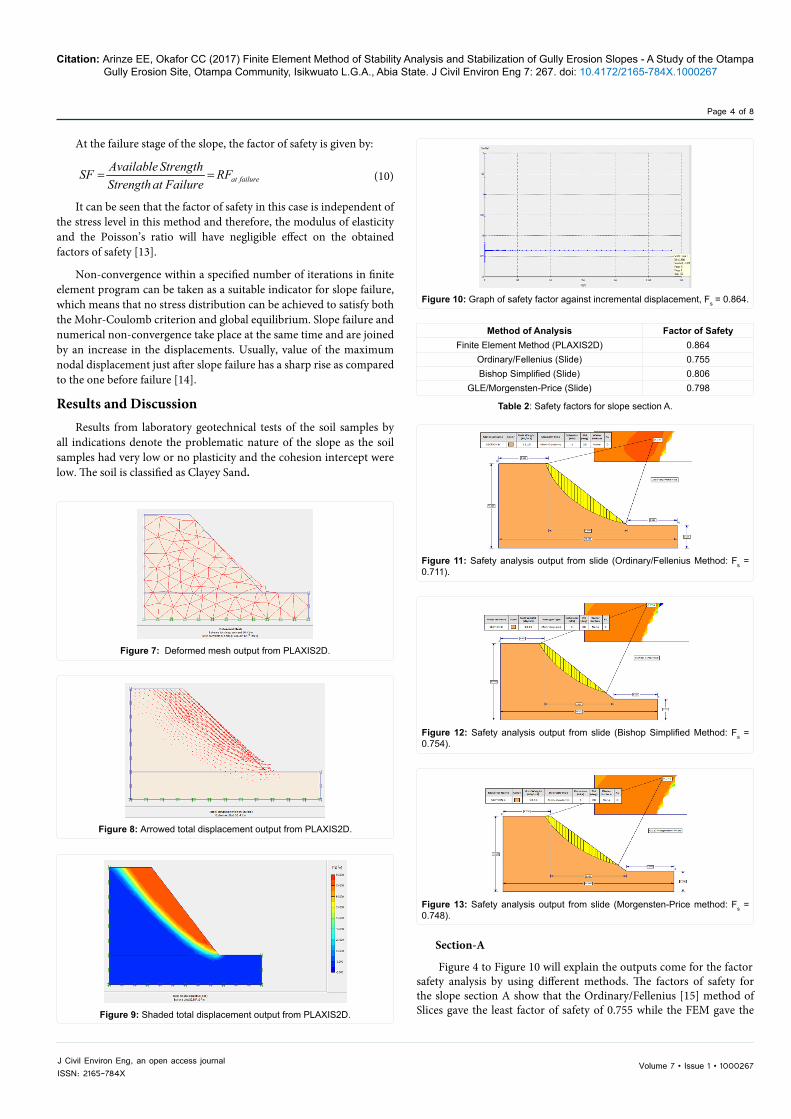
Figure 4 to Figure 10 will explain the outputs come for the factor safety analysis by using different methods. The factors of safety for the slope section A show that the Ordinary/Fellenius [15] method of Slices gave the least factor of safety of 0.755 while the FEM gave the
Figure 7: Deformed mesh output from PLAXIS2D.
Figure 8: Arrowed total displacement output from PLAXIS2D.
Figure 9: Shaded total displacement output from PLAXIS2D.
Figure 10: Graph of safety factor against incremental displacement, Fs = 0.864.
Method of Analysis Factor of SafetyFinite Element Method (PLAXIS2D) 0.864
Ordinary/Fellenius (Slide) 0.755Bishop Simplified (Slide) 0.806
GLE/Morgensten-Price (Slide) 0.798
Table 2: Safety factors for slope section A.
Figure 11: Safety analysis output from slide (Ordinary/Fellenius Method: Fs = 0.711).
Figure 12: Safety analysis output from slide (Bishop Simplified Method: Fs = 0.754).
Figure 13: Safety analysis output from slide (Morgensten-Price method: Fs = 0.748).
Volume 7 • Issue 1 • 1000267J Civil Environ Eng, an open access journalISSN: 2165-784X
Citation: Arinze EE, Okafor CC (2017) Finite Element Method of Stability Analysis and Stabilization of Gully Erosion Slopes - A Study of the Otampa Gully Erosion Site, Otampa Community, Isikwuato L.G.A., Abia State. J Civil Environ Eng 7: 267. doi: 10.4172/2165-784X.1000267
Page 5 of 8
highest factor of safety 0.864. However, the factors of safety obtained by the FEM are in line with that of the conventional methods as the discrepancies are negligible (Table 2).
Section-B
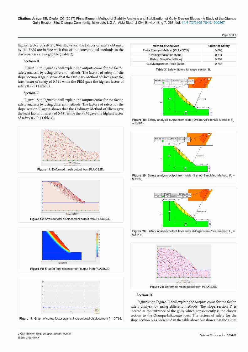
Figure 11 to Figure 17 will explain the outputs come for the factor safety analysis by using different methods. The factors of safety for the slope section B again shows that the Ordinary Method of Slices gave the least factor of safety of 0.711 while the FEM gave the highest factor of safety 0.795 (Table 3).
Section-C
Figure 18 to Figure 24 will explain the outputs come for the factor safety analysis by using different methods. The factors of safety for the slope section C again shows that the Ordinary Method of Slices gave the least factor of safety of 0.681 while the FEM gave the highest factor of safety 0.782 (Table 4).
Section-D
Figure 25 to Figure 32 will explain the outputs come for the factor safety analysis by using different methods. The slope section D is located at the entrance of the gully which consequently is the closest section to the Otampa-Isikwuato road. The factors of safety for the slope section D as presented in the table above but shows that the Finite
Figure 14: Deformed mesh output from PLAXIS2D.
Figure 15: Arrowed total displacement output from PLAXIS2D.
Figure 16: Shaded total displacement output from PLAXIS2D.
Figure 17: Graph of safety factor against increamental displacement fs = 0.795.
Method of Analysis Factor of SafetyFinite Element Method (PLAXIS2D) 0.795
Ordinary/Fellenius (Slide) 0.711Bishop Simplified (Slide) 0.754
GLE/Morgensten-Price (Slide) 0.748
Table 3: Safety factors for slope section B.
Figure 18: Safety analysis output from slide (Ordinary/Fellenius Method: Fs = 0.681).
Figure 19: Safety analysis output from slide (Bishop Simplified Method: Fs = 0.719).
Figure 20: Safety analysis output from slide (Morgensten-Price method: Fs = 0.714).
Figure 21: Deformed mesh output from PLAXIS2D.

Volume 7 • Issue 1 • 1000267J Civil Environ Eng, an open access journalISSN: 2165-784X
Citation: Arinze EE, Okafor CC (2017) Finite Element Method of Stability Analysis and Stabilization of Gully Erosion Slopes - A Study of the Otampa Gully Erosion Site, Otampa Community, Isikwuato L.G.A., Abia State. J Civil Environ Eng 7: 267. doi: 10.4172/2165-784X.1000267
Page 6 of 8
Element Method gave the least factor of safety of 1.354 (Table 5) while the Morgensten-Price Method [16] gave the highest factor of safety of 1.688. However, the factors of safety obtained by the FEM is in line with that of the conventional methods.
This particular slope section seems to be safe beyond reasonable doubt but suffers soil erosion due to the poor nature of the soil as it is non-plastic and has no cohesion whatsoever, these poor characteristics
Figure 22: Arrowed total displacement output from PLAXIS2D.
Figure 23: Shaded total displacement output from PLAXIS2D.
Figure 24: Graph of safety factor against incremental displacement Fs = 0.782.
Method of Analysis Factor of SafetyFinite Element Method (PLAXIS2D) 0.782
Ordinary/Fellenius (Slide) 0.681Bishop Simplified (Slide) 0.719
GLE/Morgensten-Price (Slide) 0.714
Table 4: Safety factors for slope section C.
Figure 25: Safety analysis output from slide (Ordinary/Fellenius Method:Fs = 1.676).
Figure 26: Safety analysis output from slide (Bishop Simplified Method: Fs = 1.690).
Figure 27: Safety analysis output from slide (Morgensten-Price method: Fs = 1.688).
Figure 28: Deformed mesh output from PLAXIS2D.
Figure 29: Arrowed total displacement output from PLAXIS2D.
Figure 30: Shaded total displacement output from PLAXIS2D.

Volume 7 • Issue 1 • 1000267J Civil Environ Eng, an open access journalISSN: 2165-784X
Citation: Arinze EE, Okafor CC (2017) Finite Element Method of Stability Analysis and Stabilization of Gully Erosion Slopes - A Study of the Otampa Gully Erosion Site, Otampa Community, Isikwuato L.G.A., Abia State. J Civil Environ Eng 7: 267. doi: 10.4172/2165-784X.1000267
Page 7 of 8
make this zone highly erodible due to surface runoff as the soil particles are easily transported by the running water.
A summary of the calculated factor of safety from the various methods of analysis for all the respective slope sections is presented in (Table 6). The plot below indicates that the FEM is reasonably in line with the LEM but has significant changes for cohesionless soils thus is more cohesion-sensitive than the LEM.
Stability analysis of the recommended stabilization methods
Section-C
A retaining wall of 4m height above ground level, penetration depth 1meter below ground surface and a base of 3m or at least 2m, coupled with optional grading of the slope to attain more stability. This grading and flattening of the slope is optional in the sense that it can
be done alongside the construction of the retaining wall to attain and investigate immediate stability of the slopes or can be left to be attained over time based on natural processes as any soil mass slide will not be harmful as the retaining wall is in place to provide lateral stability (Figure 33 and Figure 34).
Section-D
This will be analysed based on stability against soil mass sliding with the initial soil geotechnical parameters. The model created with PLAXIS2D is shown in Figure 35 and the yellow line represents the cement grout body while the blue line represents the earth retaining structure. The factor of safety have been improved from 1.354 to 1.375 as indicated from the chart of factor of safety against incremental displacement shown in Figure 36.
Figure 31: Graph of safety factor against incremental displacement fs = 1.354.
Figure 32: Plot of safety factors of various methods against slope sections.
Method of Analysis Factor of SafetyFinite Element Method (PLAXIS2D) 1.354
Ordinary/Fellenius (Slide) 1.676Bishop Simplified (Slide) 1.690
GLE/Morgensten-price (Slide) 1.688
Table 5: Safety factors for slope section D.
Method of AnalysisFactor of Safety of Various Slope Sections
A B C DFEM (PLAXIS2D) 0.864 0.795 0.782 1.354
O.F.M (Slide) 0.755 0.711 0.681 1.676B.M. (Slide) 0.806 0.754 0.719 1.690
GLE/M-P (Slide) 0.798 0.748 0.714 1.688Stability Critical Critical Most Critical Stable
Table 6: Tabular presentation of the safety factors according to the method of analysis.
Figure 33: Modelling of the retaining wall in plaxis2d for the first case.
Figure 34: Safety factor chart for the first case shows a safety factor of 1.394.
Figure 35: Modelling of the cement grout body in plaxis2d for the slope section D.
Figure 36: Safety factor chart for slope section d shows a safety factor of 1.375.

Volume 7 • Issue 1 • 1000267J Civil Environ Eng, an open access journalISSN: 2165-784X
Citation: Arinze EE, Okafor CC (2017) Finite Element Method of Stability Analysis and Stabilization of Gully Erosion Slopes - A Study of the Otampa Gully Erosion Site, Otampa Community, Isikwuato L.G.A., Abia State. J Civil Environ Eng 7: 267. doi: 10.4172/2165-784X.1000267
Page 8 of 8
Conclusion and RecommendationsInstability of gully erosion slopes is a major concern in the Otampa
community where failures cause serious destruction of the surrounding landed property and significant destruction of the Okigwe-Mbalano road. These gully erosion slope often fail rapidly during the rainy season due to increase in surcharge loads, soil strength reduction, denudation and weathering of the total soil mass.
The erosion site has been studied and the respective gully slopes coined out have been analysed with the respective soil geotechnical parameters. Geotechnical laboratory experiments show that the soil is problematic.
The various soil samples obtained from the site have considerably low plastic limits and the cohesion intercept of the various soil samples are very low and for some points, the soil samples are purely cohesion-less.
The various slope sections have been analysed and apparently, slope sections A, B, and C are unsafe as they possess very low factors of safety in the range of 0.6 – 0.8 hence it is expected that the gully erosion slopes will continue to fail if not checked. Slope section D seems to be safe in terms of factor of safety but suffers massive soil loss to the erosive action of surface runoff as the soil there is purely cohesion-less and non-plastic.
Since the main gully erosion slopes are highly unsafe owing to the fact that the respective factors of safety are very low considering the safety limit to be 1.25 which is satisfactory for routine cuts and fill, it is recommended that engineering measures be taken to curb further failure of the gully slope soil mass.
Unsafe slope failing due to sliding can be improved and made safe. Various methods are practicable for the improvement of slopes most of which involves the reduction of the sliding soil mass or the strengthening of the soil in the failure zone.
Excavations cut and fill operations and installation of sheet piles and retaining walls are generally expensive, however the goal of slope stability is a trade-off between economy and safety to provide a resulted slope which is safe, not too flat and not too steep.
The analysis and result of the chosen slope sections in this work shows that slope section C is the most unsafe slope and has been selected for stability improvement and design. Also, the slope section D has been selected to combat the massive soil loss due to action of running water.
(a) Stability of Slope Section C
This slope is stabilised against failure due to slope instability. The soil geotechnical parameters indicate very poor soil strength parameters. The cohesion intercept is as low as 1 kN/m2 and the topography seems to be the steepest, hence installation of retaining walls along the sides of the main gully is recommended. The effect of which has been analysed and have been seen to have improved up to a factor of safety of 1.394.
(b) Stability of Slope Section D
Slope section D is already stable in terms of factor of safety as already mentioned but suffers massive and progressive soil loss due to action of running water/runoff hence should be stabilised in that respect.
In most cases, conventional soil stabilisation methods which increase the soil strength are used but due to the non-plastic and cohesion-less nature of the soil at the entrance of the gully which
happens to be closest to the road, the soil will tend to be prone to high infiltration and if this happens, the soil having no cohesion whatsoever will easily be transported and eroded.
Hence, consolidation is required to increase the soil strength, after which cement grouting of the soil surface accompanied with stone pitching is recommended. This will effectively increase the safety against sliding, prevent infiltration and percolation, and prevent washing away and further weathering of the soil surface.
Generally, a study of the erosion site shows that the area is poorly drained as the entire area has only one drainage channel leading to the main erosion gully. Hence, it is recommended that more drains should be constructed to improve the drainage around the eroding area which leads to the gully. This will help in controlling the movement of running water and reduce erosion. The drains should be constructed in such a way to reduce the velocity of the running water approaching the gully so as to prevent scouring of the retaining walls/channels in the gully.
References
1. Matthews C, Farook Z, Helm P (2014) Slope stability analysis–limit equilibrium or the finite element method. Ground Engineering:22-8.
2. Arora KR (2011) Soil mechanics and foundation engineering (Geotechnical Engineering), Standard Publishers Distributors.
3. Drucker DC, Prager W (1952) Soil mechanics and plastic analysis or limit design. Quarterly of applied mathematics. 10(2):157-65.
4. Radoslaw ML (1995) Slope stability analysis: A Kinematical approach, Geotechniques. 45: 283-93.
5. Donald IB, Chen ZY (1997) Slope stability analysis by the upper bound approach: Fundamentals and methods. Canadian Geotechnical Journal 34: 853-862.
6. Duncan JM (1996) State of the Art: Limit equilibrium and finite element analysis of slopes. Journal of Geotechnical Engineering. 122 (7): 577- 596.
7. Clough RW, Woodward RJ (1967) Analysis of embankment stress and deformations. Journal of Soil Mechanics and Foundation Division, ASCE, 93(4): 529–549.
8. Chowdhury RN (1981) Discussion of stability analysis of embankment and slope. Journal of the Geotechnical Engineering Division, ASCE, 107(5): 691–693.
9. Abramson LW, Lee TS, Sharma S, Boyce GM (2002) Slope stability and stabilization methods, (2ndedn), New York, USA, John Wiley & Sons.
10. Wong FS (1984) Uncertainties in FE modelling of slope stability. Computers & Structures, 19(5/6): 777–779
11. Bishop AW (1955) The use of the slip circle in the stability analysis of slopes. Geotechnique 5(1): 7-17
12. Brinkgreve RBJ, Vermeer PA (2001) PLAXIS 3D Tunnel, Balkema Publishers.
13. Albataineh N (2006) Slope stability analysis using 2D and 3D methods. The University of Akron.
14. Verma D, Kainthola A, Gupte SS, Singh TN (2013) A finite element approach of stability analysis of internal dump slope in Wardha valley coal field, India, Maharashtra. American Journal of Mining and Metallurgy. 1(1): 1-6.
15. Fellenius W (1936) Calculation of the stability of earth dams. Transactions, (2ndedn) Geotechnique, London. 5(1): 7-17.
16. Morgenstern NR, Price VE (1965) The analysis of the stability of general slip surface. Geotechnique. 15(4): 289-290.
Citation: Arinze EE, Okafor CC (2017) Finite Element Method of Stability Analysis and Stabilization of Gully Erosion Slopes - A Study of the Otampa Gully Erosion Site, Otampa Community, Isikwuato L.G.A., Abia State. J Civil Environ Eng 7: 267. doi: 10.4172/2165-784X.1000267