object-oriented and classical software engineering ...jsumey/cet490/ppts/se8_ch12_v5.pdf · design...
TRANSCRIPT
CET/CSC490 Software Engineering Analysis
10/3/2017
CET/CSC490: Software Engineering 1
Slide 12.1
Copyright © 2011 by The McGraw-Hill Companies, Inc. All rights reserved.
Object-Oriented and Classical Software
Engineering
Eighth Edition, WCB/McGraw-Hill, 2011
Stephen R. Schach
Slide 12.2
Copyright © 2011 by The McGraw-Hill Companies, Inc. All rights reserved.
CHAPTER 12
CLASSICAL ANALYSIS
Slide 12.3
Copyright © 2011 by The McGraw-Hill Companies, Inc. All rights reserved.
Overview
The specification document
Informal specifications
Structured systems analysis
Structured systems analysis: The MSG Foundation case study
Other semiformal techniques
Entity-relationship modeling
Finite state machines
Petri nets
Z
Slide 12.4
Copyright © 2011 by The McGraw-Hill Companies, Inc. All rights reserved.
Overview (contd)
Other formal techniques
Comparison of classical analysis techniques
Testing during classical analysis
CASE tools for classical analysis
Metrics for classical analysis
Software project management plan: The MSG Foundation case study
Challenges of classical analysis
Slide 12.5
Copyright © 2011 by The McGraw-Hill Companies, Inc. All rights reserved.
The Specification Document Must Be
Informal enough for the client– The client is generally not a computer specialist
Formal enough for the developers– It is the sole source of information for drawing up the
design
These two requirements are mutually contradictory
Slide 12.6
Copyright © 2011 by The McGraw-Hill Companies, Inc. All rights reserved.
12.1 The Specification Document
The specification document is a contract between the client and the developers
Typical constraints– Deadline
– Parallel running
– Portability
– Reliability
– Rapid response time
For real-time software– Hard real-time constraints must be satisfied

CET/CSC490 Software Engineering Analysis
10/3/2017
CET/CSC490: Software Engineering 2
Slide 12.7
Copyright © 2011 by The McGraw-Hill Companies, Inc. All rights reserved.
Specification Document (contd)
Acceptance criteria– It is vital to spell out a series of tests
If the product passes the tests, it is deemed have satisfied its specifications
Some acceptance criteria are restatements of constraints
Slide 12.8
Copyright © 2011 by The McGraw-Hill Companies, Inc. All rights reserved.
Solution Strategy
A general approach to building the product
Find strategies without worrying about constraints – Then modify the strategies in the light of the constraints,
if necessary
Keep a written record of all discarded strategies, and why they were discarded– To protect the analysis team
– To prevent unwise new “solutions” during postdelivery maintenance
Slide 12.9
Copyright © 2011 by The McGraw-Hill Companies, Inc. All rights reserved.
12.2 Informal Specifications
Informal specifications are written in a natural language– Examples: English, Mandarin, Kiswahili, Hindi
Example“If the sales for the current month are below the target sales, then a report is to be printed, unless the difference between target sales and actual sales is less than half of the difference between target sales and actual sales in the previous month, or if the difference between target sales and actual sales for the current month is under 5%”
Slide 12.10
Copyright © 2011 by The McGraw-Hill Companies, Inc. All rights reserved.
The Meaning of This Specification
The sales target for January was $100,000, but actual sales were only $64,000 (36% below target)– Print the report
The sales target for February was $120,000, the actual sales were only $100,000 (16.7% below target)– The percentage difference for February (16.7%) is less
than half of the previous month’s percentage difference (36%), so do not print the report
Slide 12.11
Copyright © 2011 by The McGraw-Hill Companies, Inc. All rights reserved.
The Meaning of This Specification (contd)
The sales target for March was $100,000, the actual sales were $98,000 (2% below target)– The percentage difference is under 5%, so do not print
the report
Slide 12.12
Copyright © 2011 by The McGraw-Hill Companies, Inc. All rights reserved.
But the Specifications Do Not Say This
“[D]ifference between target sales and actual sales”– There is no mention of percentage difference in the
specifications
The difference in January was $36,000, the difference in February was $20,000– Not less than half of $36,000, so the report is printed
“[D]ifference … [of] 5%” – Again, no mention of percentage
CET/CSC490 Software Engineering Analysis
10/3/2017
CET/CSC490: Software Engineering 3
Slide 12.13
Copyright © 2011 by The McGraw-Hill Companies, Inc. All rights reserved.
But the Specifications Do Not Say This (contd)
Ambiguity—should the last clause read “percentage difference … [of] 5%” or “difference … [of] $5,000” or something else entirely?
The style is poor – The specifications should state when the report should
be printed …
– … Rather than when it should not be printed
Slide 12.14
Copyright © 2011 by The McGraw-Hill Companies, Inc. All rights reserved.
Informal Specifications (contd)
Claim– This cannot arise with professional specifications writers
Refutation– Text processing case study
Slide 12.15
Copyright © 2011 by The McGraw-Hill Companies, Inc. All rights reserved.
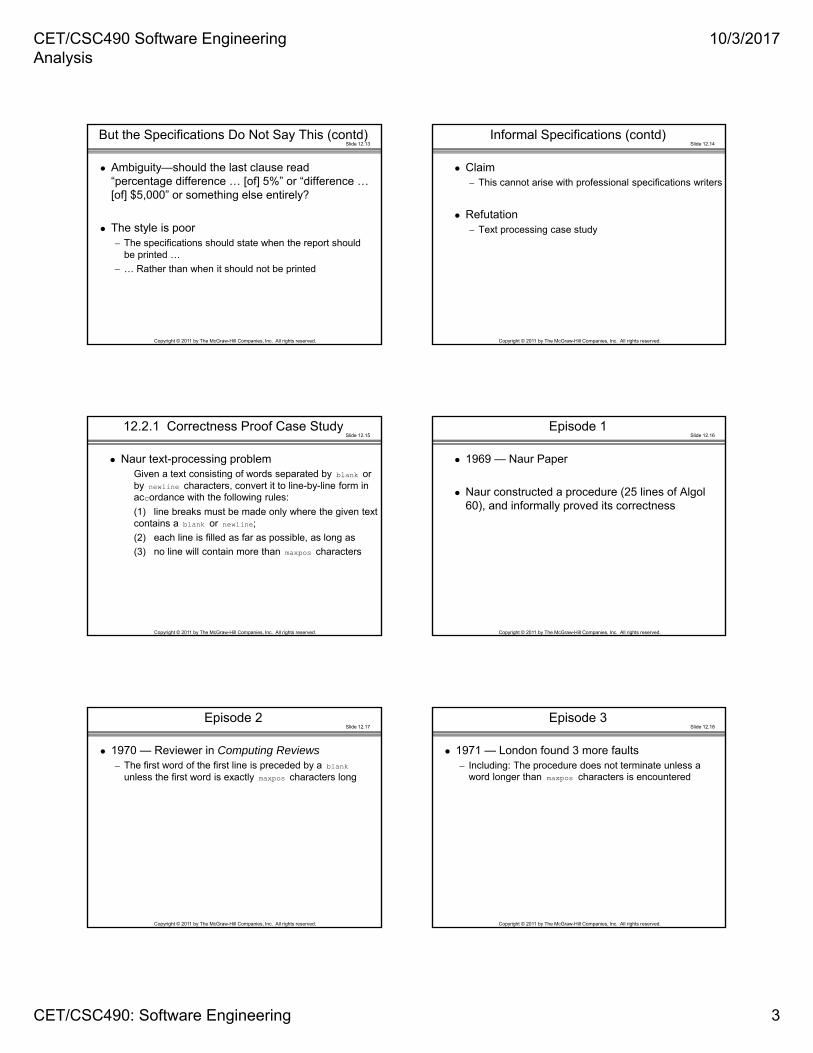
12.2.1 Correctness Proof Case Study
Naur text-processing problemGiven a text consisting of words separated by blank or by newline characters, convert it to line-by-line form in accordance with the following rules:
(1) line breaks must be made only where the given text contains a blank or newline;
(2) each line is filled as far as possible, as long as
(3) no line will contain more than maxpos characters
Slide 12.16
Copyright © 2011 by The McGraw-Hill Companies, Inc. All rights reserved.
Episode 1
1969 — Naur Paper
Naur constructed a procedure (25 lines of Algol 60), and informally proved its correctness
Slide 12.17
Copyright © 2011 by The McGraw-Hill Companies, Inc. All rights reserved.
Episode 2
1970 — Reviewer in Computing Reviews– The first word of the first line is preceded by a blank
unless the first word is exactly maxpos characters long
Slide 12.18
Copyright © 2011 by The McGraw-Hill Companies, Inc. All rights reserved.
Episode 3
1971 — London found 3 more faults– Including: The procedure does not terminate unless a
word longer than maxpos characters is encountered

CET/CSC490 Software Engineering Analysis
10/3/2017
CET/CSC490: Software Engineering 4
Slide 12.19
Copyright © 2011 by The McGraw-Hill Companies, Inc. All rights reserved.
Episode 4
1975 — Goodenough and Gerhart found 3 further faults– Including: The last word will not be output unless it is
followed by a blank or newline
Goodenough and Gerhart then produced a new set of specifications, about four times longer than Naur’s
Slide 12.20
Copyright © 2011 by The McGraw-Hill Companies, Inc. All rights reserved.
Episode 5
1985 — Meyer detected 12 faults in Goodenough and Gerhart’s specifications
Slide 12.21
Copyright © 2011 by The McGraw-Hill Companies, Inc. All rights reserved.
Episode 5
Goodenough and Gerhart’s specifications – Were constructed with the greatest of care
– Were constructed to correct Naur’s specifications
– Went through two versions, carefully refereed
– Were written by experts in specifications,
– With as much time as they needed,
– For a product about 30 lines long
So, what chance do we have of writing fault-free specifications for a real product?
Slide 12.22
Copyright © 2011 by The McGraw-Hill Companies, Inc. All rights reserved.
Episode 6
1989 — Schach found a fault in Meyer’s specifications– Item (2) of Naur’s original requirement (“each line is
filled as far as possible”) is not satisfied
Slide 12.23
Copyright © 2011 by The McGraw-Hill Companies, Inc. All rights reserved.
Informal Specifications (contd)
Conclusion– Natural language is not a good way to specify a product
Slide 12.24
Copyright © 2011 by The McGraw-Hill Companies, Inc. All rights reserved.
12.3 Structured Systems Analysis
Three popular graphical specification methods of 1970s– DeMarco
– Gane and Sarsen
– Yourdon
All are equivalent
All are equally good

CET/CSC490 Software Engineering Analysis
10/3/2017
CET/CSC490: Software Engineering 5
Slide 12.25
Copyright © 2011 by The McGraw-Hill Companies, Inc. All rights reserved.
12.3 Structured Systems Analysis (contd)
Many U.S. corporations use them for commercial products
Gane and Sarsen’s method is taught here because it is so widely used
Slide 12.26
Copyright © 2011 by The McGraw-Hill Companies, Inc. All rights reserved.
12.3.1 Sally’s Software Shop Mini Case Study
Sally’s Software Shop buys software from various suppliers and sells it to the public. Popular software packages are kept in stock, but the rest must be ordered as required. Institutions and corporations are given credit facilities, as are some members of the public. Sally’s Software Shop is doing well, with a monthly turnover of 300 packages at an average retail cost of $250 each. Despite her business success, Sally has been advised to computerize. Should she?
Slide 12.27
Copyright © 2011 by The McGraw-Hill Companies, Inc. All rights reserved.
Sally’s Software Shop Mini Case Study (contd)
A better question– What business functions should she computerize
» Accounts payable
» Accounts receivable
» Inventory
Still better– How? Batch, or online? In-house or outsourcing?
Slide 12.28
Copyright © 2011 by The McGraw-Hill Companies, Inc. All rights reserved.
Sally’s Software Shop Mini Case Study (contd)
The fundamental issue – What is Sally’s objective in computerizing her business?
Because she sells software?– She needs an in-house system with sound and light
effects
Because she uses her business to launder “hot” money?– She needs a product that keeps five different sets of
books, and has no audit trail
Slide 12.29
Copyright © 2011 by The McGraw-Hill Companies, Inc. All rights reserved.
Sally’s Software Shop Mini Case Study (contd)
We assume: Sally wishes to computerize “in order to make more money” – We need to perform cost–benefit analysis for each
section of her business
Slide 12.30
Copyright © 2011 by The McGraw-Hill Companies, Inc. All rights reserved.
Sally’s Software Shop Mini Case Study (contd)
The danger of many standard approaches – First produce the solution, then find out what the
problem is!
Gane and Sarsen’s method– Nine-step method
– Stepwise refinement is used in many steps

CET/CSC490 Software Engineering Analysis
10/3/2017
CET/CSC490: Software Engineering 6
Slide 12.31
Copyright © 2011 by The McGraw-Hill Companies, Inc. All rights reserved.
Sally’s Software Shop Mini Case Study (contd)
The data flow diagram (DFD) shows the logical data flow – “What happens, not
how it happens”
Symbols:
Figure 12.1
Slide 12.32
Copyright © 2011 by The McGraw-Hill Companies, Inc. All rights reserved.
Step 1. Draw the DFD
First refinement– Infinite number of possible interpretations
Figure 12.2
Slide 12.33
Copyright © 2011 by The McGraw-Hill Companies, Inc. All rights reserved.
Step 1 (contd)
Second refinement– PENDING ORDERS is scanned daily
Figure 12.3
Slide 12.34
Copyright © 2011 by The McGraw-Hill Companies, Inc. All rights reserved.
Step 1 (contd)
Portion of third refinement
Figure 12.4
Slide 12.35
Copyright © 2011 by The McGraw-Hill Companies, Inc. All rights reserved.
Step 1 (contd)
The final DFD is larger– But it is easily understood by the client
When dealing with larger DFDs– Set up a hierarchy of DFDs– A box becomes a DFD at a lower level
Slide 12.36
Copyright © 2011 by The McGraw-Hill Companies, Inc. All rights reserved.
Step 2. Decide What Parts to Computerize and How
It depends on how much client is prepared to spend
Large volumes, tight controls– Batch
Small volumes, in-house microcomputer– Online
Cost/benefit analysis
CET/CSC490 Software Engineering Analysis
10/3/2017
CET/CSC490: Software Engineering 7
Slide 12.37
Copyright © 2011 by The McGraw-Hill Companies, Inc. All rights reserved.
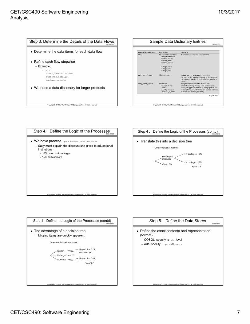
Step 3. Determine the Details of the Data Flows
Determine the data items for each data flow
Refine each flow stepwise– Example;
order:
order_identification
customer_details
package_details
We need a data dictionary for larger products
Slide 12.38
Copyright © 2011 by The McGraw-Hill Companies, Inc. All rights reserved.
Sample Data Dictionary Entries
Figure 12.5
Slide 12.39
Copyright © 2011 by The McGraw-Hill Companies, Inc. All rights reserved.
Step 4. Define the Logic of the Processes
We have process give educational discount
– Sally must explain the discount she gives to educational institutions
» 10% on up to 4 packages
» 15% on 5 or more
Slide 12.40
Copyright © 2011 by The McGraw-Hill Companies, Inc. All rights reserved.
Step 4 . Define the Logic of the Processes (contd)
Translate this into a decision tree
Figure 12.6
Slide 12.41
Copyright © 2011 by The McGraw-Hill Companies, Inc. All rights reserved.
Step 4. Define the Logic of the Processes (contd)
The advantage of a decision tree– Missing items are quickly apparent
Figure 12.7
Slide 12.42
Copyright © 2011 by The McGraw-Hill Companies, Inc. All rights reserved.
Step 5. Define the Data Stores
Define the exact contents and representation (format) – COBOL: specify to pic level
– Ada: specify digits or delta
CET/CSC490 Software Engineering Analysis
10/3/2017
CET/CSC490: Software Engineering 8
Slide 12.43
Copyright © 2011 by The McGraw-Hill Companies, Inc. All rights reserved.
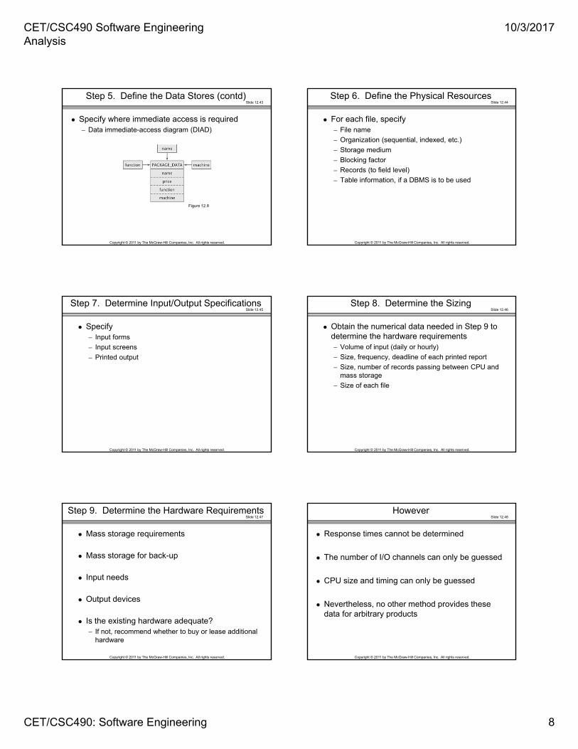
Step 5. Define the Data Stores (contd)
Specify where immediate access is required– Data immediate-access diagram (DIAD)
Figure 12.8
Slide 12.44
Copyright © 2011 by The McGraw-Hill Companies, Inc. All rights reserved.
Step 6. Define the Physical Resources
For each file, specify– File name
– Organization (sequential, indexed, etc.)
– Storage medium
– Blocking factor
– Records (to field level)
– Table information, if a DBMS is to be used
Slide 12.45
Copyright © 2011 by The McGraw-Hill Companies, Inc. All rights reserved.
Step 7. Determine Input/Output Specifications
Specify – Input forms
– Input screens
– Printed output
Slide 12.46
Copyright © 2011 by The McGraw-Hill Companies, Inc. All rights reserved.
Step 8. Determine the Sizing
Obtain the numerical data needed in Step 9 to determine the hardware requirements– Volume of input (daily or hourly)
– Size, frequency, deadline of each printed report
– Size, number of records passing between CPU and mass storage
– Size of each file
Slide 12.47
Copyright © 2011 by The McGraw-Hill Companies, Inc. All rights reserved.
Step 9. Determine the Hardware Requirements
Mass storage requirements
Mass storage for back-up
Input needs
Output devices
Is the existing hardware adequate?– If not, recommend whether to buy or lease additional
hardware
Slide 12.48
Copyright © 2011 by The McGraw-Hill Companies, Inc. All rights reserved.
However
Response times cannot be determined
The number of I/O channels can only be guessed
CPU size and timing can only be guessed
Nevertheless, no other method provides these data for arbitrary products
CET/CSC490 Software Engineering Analysis
10/3/2017
CET/CSC490: Software Engineering 9
Slide 12.49
Copyright © 2011 by The McGraw-Hill Companies, Inc. All rights reserved.
Overall
The method of Gane and Sarsen/De Marco/ Yourdon has resulted in major improvements in the software industry
Slide 12.50
Copyright © 2011 by The McGraw-Hill Companies, Inc. All rights reserved.
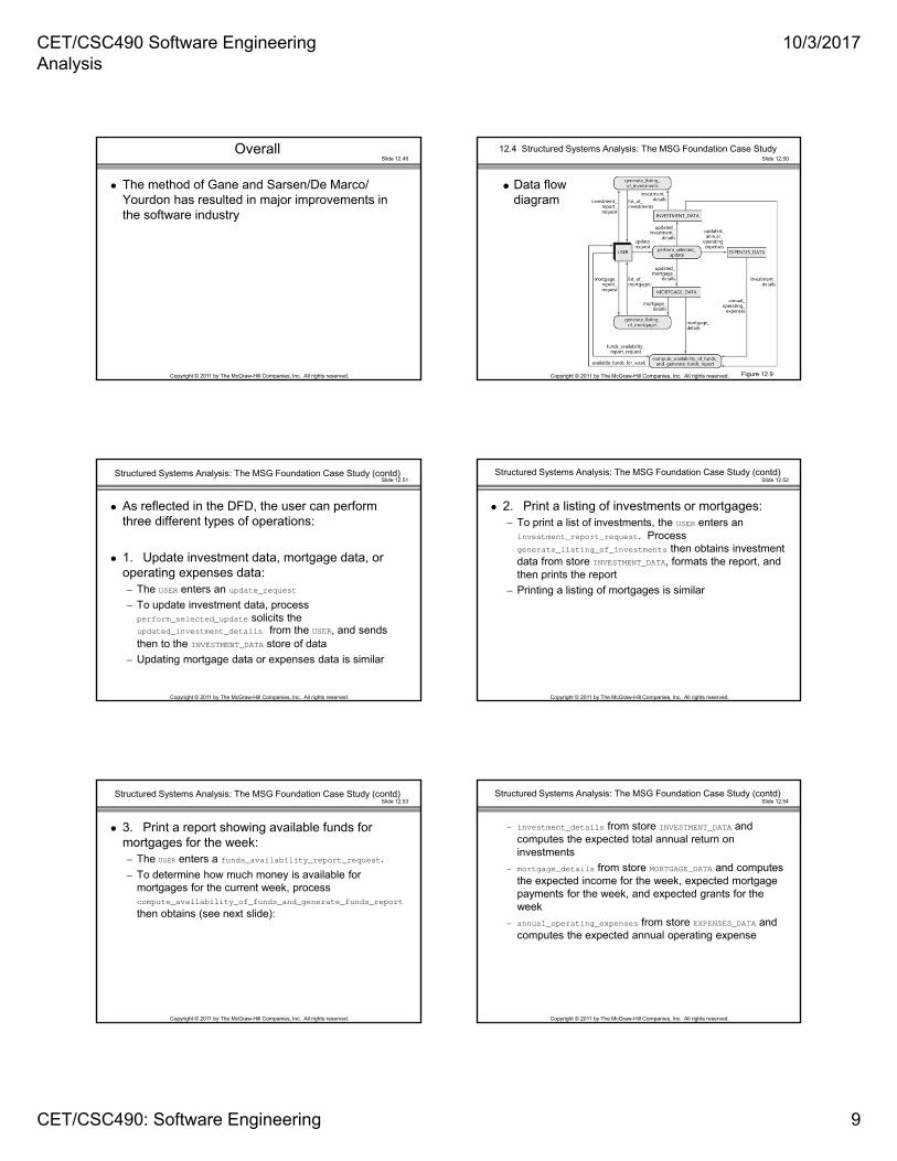
12.4 Structured Systems Analysis: The MSG Foundation Case Study
Figure 12.9
Data flow diagram
Slide 12.51
Copyright © 2011 by The McGraw-Hill Companies, Inc. All rights reserved.
Structured Systems Analysis: The MSG Foundation Case Study (contd)
As reflected in the DFD, the user can perform three different types of operations:
1. Update investment data, mortgage data, or operating expenses data:– The USER enters an update_request
– To update investment data, process perform_selected_update solicits the updated_investment_details from the USER, and sends then to the INVESTMENT_DATA store of data
– Updating mortgage data or expenses data is similar
Slide 12.52
Copyright © 2011 by The McGraw-Hill Companies, Inc. All rights reserved.
Structured Systems Analysis: The MSG Foundation Case Study (contd)
2. Print a listing of investments or mortgages:– To print a list of investments, the USER enters an
investment_report_request. Process generate_listing_of_investments then obtains investment data from store INVESTMENT_DATA, formats the report, and then prints the report
– Printing a listing of mortgages is similar
Slide 12.53
Copyright © 2011 by The McGraw-Hill Companies, Inc. All rights reserved.
Structured Systems Analysis: The MSG Foundation Case Study (contd)
3. Print a report showing available funds for mortgages for the week:– The USER enters a funds_availability_report_request.
– To determine how much money is available for mortgages for the current week, process compute_availability_of_funds_and_generate_funds_report
then obtains (see next slide):
Slide 12.54
Copyright © 2011 by The McGraw-Hill Companies, Inc. All rights reserved.
Structured Systems Analysis: The MSG Foundation Case Study (contd)
– investment_details from store INVESTMENT_DATA and computes the expected total annual return on investments
– mortgage_details from store MORTGAGE_DATA and computes the expected income for the week, expected mortgage payments for the week, and expected grants for the week
– annual_operating_expenses from store EXPENSES_DATA and computes the expected annual operating expense

CET/CSC490 Software Engineering Analysis
10/3/2017
CET/CSC490: Software Engineering 10
Slide 12.55
Copyright © 2011 by The McGraw-Hill Companies, Inc. All rights reserved.
Structured Systems Analysis: The MSG Foundation Case Study (contd)
Process compute_availability_of_funds_and_ generate_funds_report then uses these results to compute available_funds_for_week, and format and print the report
Slide 12.56
Copyright © 2011 by The McGraw-Hill Companies, Inc. All rights reserved.
12.5 Other Semiformal Techniques
Semiformal (graphical) techniques for classical analysis include– PSL/PSA
– SADT
– SREM
Slide 12.57
Copyright © 2011 by The McGraw-Hill Companies, Inc. All rights reserved.
12.6 Entity-Relationship Modeling
Semi-formal technique– Widely used for specifying databases
– Example:
Figure 12.10
Slide 12.58
Copyright © 2011 by The McGraw-Hill Companies, Inc. All rights reserved.
Entity-Relationship Diagrams (contd)
Many-to-many relationship
Figure 12.11
Slide 12.59
Copyright © 2011 by The McGraw-Hill Companies, Inc. All rights reserved.
Entity-Relationship Diagrams (contd)
More complex entity-relationship diagrams
Figure 12.12
Slide 12.60
Copyright © 2011 by The McGraw-Hill Companies, Inc. All rights reserved.
12.7 Finite State Machines
Case studyA safe has a combination lock that can be in one of three positions, labeled 1, 2, and 3. The dial can be turned left or right (L or R). Thus there are six possible dial movements, namely 1L, 1R, 2L, 2R, 3L, and 3R. The combination to the safe is 1L, 3R, 2L; any other dial movement will cause the alarm to go off
Figure 12.13

CET/CSC490 Software Engineering Analysis
10/3/2017
CET/CSC490: Software Engineering 11
Slide 12.61
Copyright © 2011 by The McGraw-Hill Companies, Inc. All rights reserved.
Finite State Machines (contd)
The set of states J is {Safe Locked, A, B, Safe Unlocked, Sound Alarm}
The set of inputs K is {1L, 1R, 2L, 2R, 3L, 3R}
The transition function T is on the next slide
The initial state J is Safe Locked
The set of final states J is {Safe Unlocked, Sound Alarm}
Slide 12.62
Copyright © 2011 by The McGraw-Hill Companies, Inc. All rights reserved.
Figure 12.14
Finite State Machines (contd)
Transition table
Slide 12.63
Copyright © 2011 by The McGraw-Hill Companies, Inc. All rights reserved.
Extended Finite State Machines
FSM transition rules have the formcurrent state [menu] and event [option selected] new state
Extend the standard FSM by adding global predicates
Transition rules then take the formcurrent state and event and predicate new state
Slide 12.64
Copyright © 2011 by The McGraw-Hill Companies, Inc. All rights reserved.
12.7.1 Finite State Machines: The Elevator Problem Case Study
A product is to be installed to control n elevators in a building with m floors. The problem concerns the logic required to move elevators between floors according to the following constraints:1. Each elevator has a set of m buttons, one for each floor. These illuminate when pressed and cause the elevator to visit the corresponding floor. The illumination is canceled when the corresponding floor is visited by the elevator2. Each floor, except the first and the top floor, has two buttons, one to request an up-elevator, one to request a down-elevator. These buttons illuminate when pressed. The illumination is canceled when an elevator visits the floor, then moves in the desired direction 3. If an elevator has no requests, it remains at its current floor with its doors closed
Slide 12.65
Copyright © 2011 by The McGraw-Hill Companies, Inc. All rights reserved.
Finite State Machines: The Elevator Problem Case Study (contd)
There are two sets of buttons
Elevator buttons– In each elevator, one for each floor
Floor buttons– Two on each floor, one for up-elevator, one for down-
elevator
Slide 12.66
Copyright © 2011 by The McGraw-Hill Companies, Inc. All rights reserved.
Elevator Buttons
EB (e, f): – Elevator Button in elevator e pressed to request floor f

CET/CSC490 Software Engineering Analysis
10/3/2017
CET/CSC490: Software Engineering 12
Slide 12.67
Copyright © 2011 by The McGraw-Hill Companies, Inc. All rights reserved.
Elevator Buttons (contd)
Two statesEBON (e, f): Elevator Button (e, f) ON
EBOFF (e, f): Elevator Button (e, f) OFF
– If an elevator button is on and the elevator arrives at floor f, then the elevator button is turned off
– If the elevator button is off and the elevator button is pressed, then the elevator button comes on
Figure 12.15
Slide 12.68
Copyright © 2011 by The McGraw-Hill Companies, Inc. All rights reserved.
Elevator Buttons (contd)
Two eventsEBP (e, f): Elevator Button (e, f) Pressed
EHAF (e, f):Elevator e Has Arrived at Floor f
Global predicateV (e, f): Elevator e is Visiting (stopped at) floor f
Transition RulesEBOFF (e, f) and EBP (e, f) and not V (e, f) EBON (e, f)
EBON (e, f) and EHAF (e, f) EBOFF (e, f)
Slide 12.69
Copyright © 2011 by The McGraw-Hill Companies, Inc. All rights reserved.
Floor Buttons
FB (d, f):– Floor Button on floor f that requests elevator traveling in
direction d
Slide 12.70
Copyright © 2011 by The McGraw-Hill Companies, Inc. All rights reserved.
Floor Buttons (contd)
StatesFBON (d, f): Floor Button (d, f) ONFBOFF (d, f): Floor Button (d, f) OFF
– If the floor button is on and an elevator arrives at floor f, traveling in the correct direction d, then the floor button is turned off
– If the floor button is off and the floor button is pressed, then the floor button comes on
Figure 12.16
Slide 12.71
Copyright © 2011 by The McGraw-Hill Companies, Inc. All rights reserved.
Floor Buttons (contd)
EventsFBP (d, f): Floor Button (d, f) PressedEHAF (1..n, f): Elevator 1 or … or n Has Arrived at Floor f
PredicateS (d, e, f): Elevator e is visiting floor f
Direction of motion is up (d = U), down (d = D), or no requests are pending (d = N)
Transition rulesFBOFF (d, f) and FBP (d, f) and not S (d, 1..n, f) FBON (d, f)FBON (d, f) and EHAF (1..n, f) and S (d, 1..n, f) FBOFF (d, f),
d = U or D
Slide 12.72
Copyright © 2011 by The McGraw-Hill Companies, Inc. All rights reserved.
Finite State Machines: The Elevator Problem Case Study (contd)
The state of the elevator consists of component substates, including:– Elevator slowing
– Elevator stopping
– Door opening
– Door open with timer running
– Door closing after a timeout

CET/CSC490 Software Engineering Analysis
10/3/2017
CET/CSC490: Software Engineering 13
Slide 12.73
Copyright © 2011 by The McGraw-Hill Companies, Inc. All rights reserved.
Elevator Problem: FSM (contd)
We assume that the elevator controller moves the elevator through the substates
Three elevator statesM (d, e, f): Moving in direction d (floor f is next)
S (d, e, f): Stopped (d-bound) at floor f
W (e, f): Waiting at floor f (door closed)
For simplicity, the three stopped states S (U, e, f), S (N, e, f), and S (D, e, f) are grouped into one larger state
Slide 12.74
Copyright © 2011 by The McGraw-Hill Companies, Inc. All rights reserved.
State Transition Diagram for Elevator
Figure 12.17
Slide 12.75
Copyright © 2011 by The McGraw-Hill Companies, Inc. All rights reserved.
Elevator Problem: FSM (contd)
EventsDC (e, f): Door Closed for elevator e, floor f
ST (e, f): Sensor Triggered as elevator e nears floor f
RL: Request Logged (button pressed)
Transition RulesIf the elevator e is in state S (d, e, f) (stopped, d-bound, at floor f), and the doors close, then elevator e will move up, down, or go into the wait state
DC (e, f) and S (U, e, f) M (U, e, f+1)
DC (e, f) and S (D, e, f) M (D, e, f-1)
DC (e, f) and S (N, e, f) W (e, f)
Slide 12.76
Copyright © 2011 by The McGraw-Hill Companies, Inc. All rights reserved.
Finite State Machines (contd)
The power of an FSM to specify complex systems
There is no need for complex preconditions and postconditions
Specifications take the simple form current state and event and predicate next state
Slide 12.77
Copyright © 2011 by The McGraw-Hill Companies, Inc. All rights reserved.
Finite State Machines (contd)
Using an FSM, a specification is– Easy to write down
– Easy to validate
– Easy to convert into a design
– Easy to convert into code automatically
– More precise than graphical methods
– Almost as easy to understand
– Easy to maintain
However– Timing considerations are not handled
Slide 12.78
Copyright © 2011 by The McGraw-Hill Companies, Inc. All rights reserved.
Finite State Machines (contd)
Statecharts are a real-time extension of FSMs– CASE tool: Rhapsody

CET/CSC490 Software Engineering Analysis
10/3/2017
CET/CSC490: Software Engineering 14
Slide 12.79
Copyright © 2011 by The McGraw-Hill Companies, Inc. All rights reserved.
12.8 Petri Nets
A major difficulty with specifying real-time systems is timing– Synchronization problems
– Race conditions
– Deadlock
Often a consequence of poor specifications
Slide 12.80
Copyright © 2011 by The McGraw-Hill Companies, Inc. All rights reserved.
Petri Nets (contd)
Petri nets– A powerful technique for specifying systems that have
potential problems with interrelations
A Petri net consists of four parts: – A set of places P
– A set of transitions T
– An input function I
– An output function O
Slide 12.81
Copyright © 2011 by The McGraw-Hill Companies, Inc. All rights reserved.
Petri Nets (contd)
Set of places P is {p1, p2, p3, p4}
Set of transitions T
is {t1, t2}
Input functions:I(t1) = {p2, p4}
I(t2) = {p2}
Output functions:O(t1) = {p1}
O(t2) = {p3, p3}
Figure 12.18
Slide 12.82
Copyright © 2011 by The McGraw-Hill Companies, Inc. All rights reserved.
Petri Nets (contd)
More formally, a Petri net is a 4-tuple C = (P, T, I, O)
– P = {p1, p2, …, pn} is a finite set of places, n ≥ 0
– T = {t1, t2, …, tm} is a finite set of transitions, m ≥ 0, with P and T disjoint
– I : T P∞ is the input function, a mapping from transitions to bags of places
– O : T P∞ is the output function, a mapping from transitions to bags of places
– (A bag is a generalization of a set that allows for multiple instances of elements, as in the example on the previous slide)
– A marking of a Petri net is an assignment of tokens to that Petri net
Slide 12.83
Copyright © 2011 by The McGraw-Hill Companies, Inc. All rights reserved.
Petri Nets (contd)
Four tokens: one in p1, two in p2, none in p3, and one in p4
– Represented by the vector (1, 2, 0, 1)
Figure 12.19
Slide 12.84
Copyright © 2011 by The McGraw-Hill Companies, Inc. All rights reserved.
Petri Nets (contd)
A transition is enabled if each of its input places has as many tokens in it as there are arcs from the place to that transition

CET/CSC490 Software Engineering Analysis
10/3/2017
CET/CSC490: Software Engineering 15
Slide 12.85
Copyright © 2011 by The McGraw-Hill Companies, Inc. All rights reserved.
Petri Nets (contd)
Transition t1 is enabled (ready to fire)– If t1 fires, one token is removed from p2 and one from p4,
and one new token is placed in p1
Transition t2 is also enabled
Important: – The number of tokens is not conserved
Slide 12.86
Copyright © 2011 by The McGraw-Hill Companies, Inc. All rights reserved.
Petri Nets (contd)
Petri nets are indeterminate– Suppose t1 fires
The resulting marking is (2, 1, 0 ,0)
Figure 12.20
Slide 12.87
Copyright © 2011 by The McGraw-Hill Companies, Inc. All rights reserved.
Petri Nets (contd)
Now only t2 is enabled – It fires
The marking is now (2, 0, 2, 0)
Figure 12.21
Slide 12.88
Copyright © 2011 by The McGraw-Hill Companies, Inc. All rights reserved.
Petri Nets (contd)
More formally, a marking M of a Petri net C = (P, T, I, O)
is a function from the set of places P to the non-negative integers
M : P {0, 1, 2, …}
A marked Petri net is then a 5-tuple (P, T, I, O, M )
Slide 12.89
Copyright © 2011 by The McGraw-Hill Companies, Inc. All rights reserved.
Petri Nets (contd)
Inhibitor arcs– An inhibitor arc is marked by a small circle, not an
arrowhead
Transition t1 is enabled
Figure 12.22
Slide 12.90
Copyright © 2011 by The McGraw-Hill Companies, Inc. All rights reserved.
Petri Nets (contd)
In general, a transition is enabled if there is at least one token on each (normal) input arc, and no tokens on any inhibitor input arcs

CET/CSC490 Software Engineering Analysis
10/3/2017
CET/CSC490: Software Engineering 16
Slide 12.91
Copyright © 2011 by The McGraw-Hill Companies, Inc. All rights reserved.
12.8.1 Petri Nets: The Elevator Problem Case Study
A product is to be installed to control n elevators in a building with m floors
Each floor is represented by a place Ff, 1 f m
An elevator is represented by a token
A token in Ff denotes that an elevator is at floor Ff
Slide 12.92
Copyright © 2011 by The McGraw-Hill Companies, Inc. All rights reserved.
Petri Nets: The Elevator Problem Case Study (contd)
First constraint:1. Each elevator has a set of m buttons, one for each floor. These illuminate when pressed and cause the elevator to visit the corresponding floor. The illumination is canceled when the corresponding floor is visited by an elevator
The elevator button for floor f is represented by place EBf, 1 f m
A token in EBf denotes that the elevator button for floor f is illuminated
Slide 12.93
Copyright © 2011 by The McGraw-Hill Companies, Inc. All rights reserved.
Petri Nets: The Elevator Problem Case Study (contd)
A button must be illuminated the first time the button is pressed and subsequent button presses must be ignored
Slide 12.94
Copyright © 2011 by The McGraw-Hill Companies, Inc. All rights reserved.
Petri Nets: The Elevator Problem Case Study (contd)
If button EBf is not illuminated, no token is in place and transition EBf pressed is enabled – The transition fires, a new token is placed in EBf
Now, no matter how many times the button is pressed, transition EBf pressed cannot be enabled
Figure 12.23
Slide 12.95
Copyright © 2011 by The McGraw-Hill Companies, Inc. All rights reserved.
Petri Nets: The Elevator Problem Case Study (contd)
When the elevator reaches floor g
– A token is in place Fg
– Transition Elevator in action is enabled, and then fires
The tokens in EBf and Fg are removed– This turns off the light in button EBf
A new token appears in Ff
– This brings the elevator from floor g to floor f
Slide 12.96
Copyright © 2011 by The McGraw-Hill Companies, Inc. All rights reserved.
Petri Nets: The Elevator Problem Case Study (contd)
Motion from floor g to floor f cannot take place instantaneously– We need timed Petri nets
CET/CSC490 Software Engineering Analysis
10/3/2017
CET/CSC490: Software Engineering 17
Slide 12.97
Copyright © 2011 by The McGraw-Hill Companies, Inc. All rights reserved.
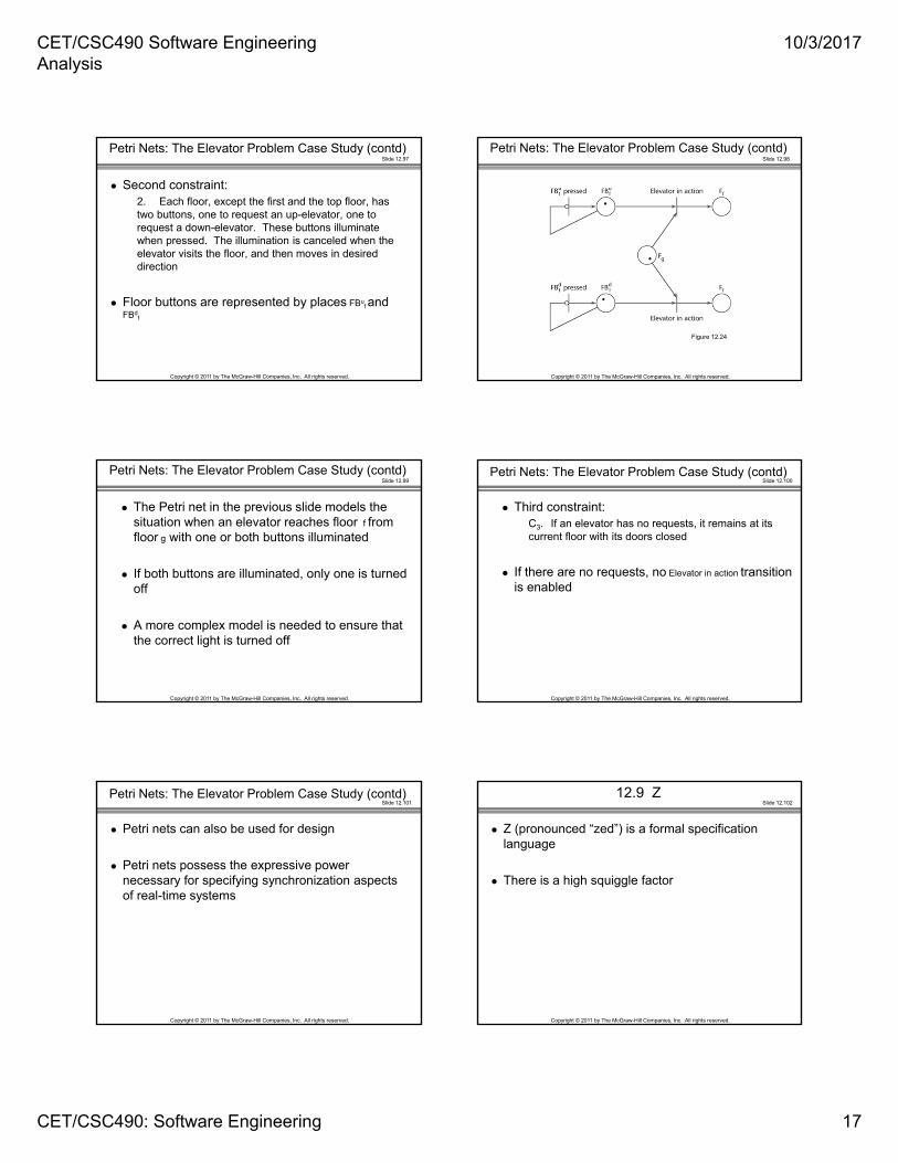
Petri Nets: The Elevator Problem Case Study (contd)
Second constraint:2. Each floor, except the first and the top floor, has two buttons, one to request an up-elevator, one to request a down-elevator. These buttons illuminate when pressed. The illumination is canceled when the elevator visits the floor, and then moves in desired direction
Floor buttons are represented by places FBuf and
FBdf
Slide 12.98
Copyright © 2011 by The McGraw-Hill Companies, Inc. All rights reserved.
Petri Nets: The Elevator Problem Case Study (contd)
Figure 12.24
Slide 12.99
Copyright © 2011 by The McGraw-Hill Companies, Inc. All rights reserved.
Petri Nets: The Elevator Problem Case Study (contd)
The Petri net in the previous slide models the situation when an elevator reaches floor f from floor g with one or both buttons illuminated
If both buttons are illuminated, only one is turned off
A more complex model is needed to ensure that the correct light is turned off
Slide 12.100
Copyright © 2011 by The McGraw-Hill Companies, Inc. All rights reserved.
Petri Nets: The Elevator Problem Case Study (contd)
Third constraint:C3. If an elevator has no requests, it remains at its current floor with its doors closed
If there are no requests, no Elevator in action transition is enabled
Slide 12.101
Copyright © 2011 by The McGraw-Hill Companies, Inc. All rights reserved.
Petri Nets: The Elevator Problem Case Study (contd)
Petri nets can also be used for design
Petri nets possess the expressive power necessary for specifying synchronization aspects of real-time systems
Slide 12.102
Copyright © 2011 by The McGraw-Hill Companies, Inc. All rights reserved.
12.9 Z
Z (pronounced “zed”) is a formal specification language
There is a high squiggle factor
CET/CSC490 Software Engineering Analysis
10/3/2017
CET/CSC490: Software Engineering 18
Slide 12.103
Copyright © 2011 by The McGraw-Hill Companies, Inc. All rights reserved.
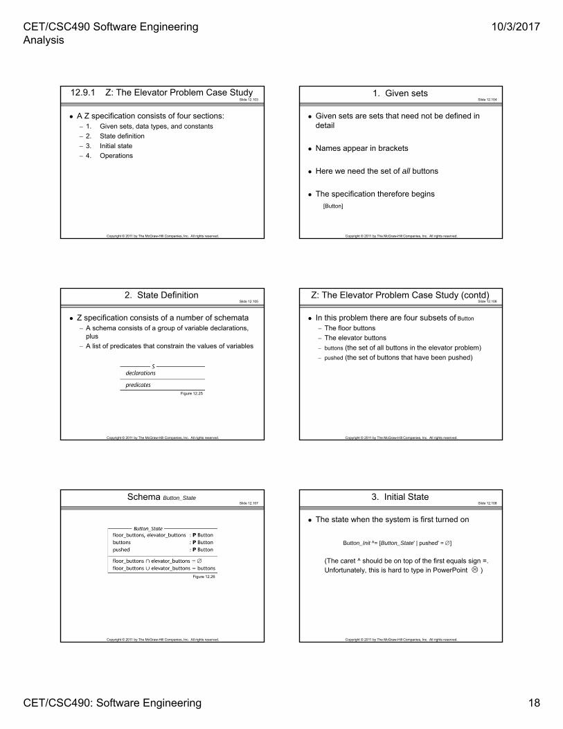
12.9.1 Z: The Elevator Problem Case Study
A Z specification consists of four sections:– 1. Given sets, data types, and constants
– 2. State definition
– 3. Initial state
– 4. Operations
Slide 12.104
Copyright © 2011 by The McGraw-Hill Companies, Inc. All rights reserved.
1. Given sets
Given sets are sets that need not be defined in detail
Names appear in brackets
Here we need the set of all buttons
The specification therefore begins
[Button]
Slide 12.105
Copyright © 2011 by The McGraw-Hill Companies, Inc. All rights reserved.
2. State Definition
Z specification consists of a number of schemata– A schema consists of a group of variable declarations,
plus
– A list of predicates that constrain the values of variables
Figure 12.25
Slide 12.106
Copyright © 2011 by The McGraw-Hill Companies, Inc. All rights reserved.
Z: The Elevator Problem Case Study (contd)
In this problem there are four subsets of Button
– The floor buttons
– The elevator buttons
– buttons (the set of all buttons in the elevator problem)
– pushed (the set of buttons that have been pushed)
Slide 12.107
Copyright © 2011 by The McGraw-Hill Companies, Inc. All rights reserved.
Schema Button_State
Figure 12.26
Slide 12.108
Copyright © 2011 by The McGraw-Hill Companies, Inc. All rights reserved.
3. Initial State
The state when the system is first turned on
Button_Init ^= [Button_State' | pushed' = ]
(The caret ^ should be on top of the first equals sign =. Unfortunately, this is hard to type in PowerPoint )
CET/CSC490 Software Engineering Analysis
10/3/2017
CET/CSC490: Software Engineering 19
Slide 12.109
Copyright © 2011 by The McGraw-Hill Companies, Inc. All rights reserved.
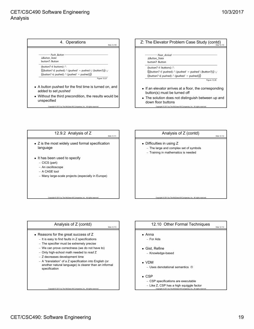
4. Operations
A button pushed for the first time is turned on, and added to set pushed
Without the third precondition, the results would be unspecified
Figure 12.27
Slide 12.110
Copyright © 2011 by The McGraw-Hill Companies, Inc. All rights reserved.
Z: The Elevator Problem Case Study (contd)
If an elevator arrives at a floor, the corresponding button(s) must be turned off
The solution does not distinguish between up and down floor buttons
Figure 12.28
Slide 12.111
Copyright © 2011 by The McGraw-Hill Companies, Inc. All rights reserved.
12.9.2 Analysis of Z
Z is the most widely used formal specification language
It has been used to specify– CICS (part)
– An oscilloscope
– A CASE tool
– Many large-scale projects (especially in Europe)
Slide 12.112
Copyright © 2011 by The McGraw-Hill Companies, Inc. All rights reserved.
Analysis of Z (contd)
Difficulties in using Z– The large and complex set of symbols
– Training in mathematics is needed
Slide 12.113
Copyright © 2011 by The McGraw-Hill Companies, Inc. All rights reserved.
Analysis of Z (contd)
Reasons for the great success of Z– It is easy to find faults in Z specifications
– The specifier must be extremely precise
– We can prove correctness (we do not have to)
– Only high-school math needed to read Z
– Z decreases development time
– A “translation” of a Z specification into English (or another natural language) is clearer than an informal specification
Slide 12.114
Copyright © 2011 by The McGraw-Hill Companies, Inc. All rights reserved.
12.10 Other Formal Techniques
Anna – For Ada
Gist, Refine– Knowledge-based
VDM – Uses denotational semantics
CSP – CSP specifications are executable
– Like Z, CSP has a high squiggle factor

CET/CSC490 Software Engineering Analysis
10/3/2017
CET/CSC490: Software Engineering 20
Slide 12.115
Copyright © 2011 by The McGraw-Hill Companies, Inc. All rights reserved.
12.11 Comparison of Classical Analysis Techniques
Formal methods are– Powerful, but
– Difficult to learn and use
Informal methods have– Little power, but are
– Easy to learn and use
There is therefore a trade-off– Ease of use versus power
Slide 12.116
Copyright © 2011 by The McGraw-Hill Companies, Inc. All rights reserved.
Comparison of Classical Analysis Techniques (contd)
Figure 12.29
Slide 12.117
Copyright © 2011 by The McGraw-Hill Companies, Inc. All rights reserved.
Newer Methods
Many are untested in practice
There are risks involved– Training costs
– Adjustment from the classroom to an actual project
– CASE tools may not work properly
However, possible gains may be huge
Slide 12.118
Copyright © 2011 by The McGraw-Hill Companies, Inc. All rights reserved.
Which Analysis Technique Should Be Used?
It depends on the– Project
– Development team
– Management team
– Myriad other factors
It is unwise to ignore the latest developments
Slide 12.119
Copyright © 2011 by The McGraw-Hill Companies, Inc. All rights reserved.
12.12 Testing during Classical Analysis
Specification inspection– Aided by fault checklist
Results of Doolan (1992)– 2 million lines of FORTRAN
– 1 hour of inspecting saved 30 hours of execution-based testing
Slide 12.120
Copyright © 2011 by The McGraw-Hill Companies, Inc. All rights reserved.
12.13 CASE Tools for Classical Analysis
A graphical tool is exceedingly useful
So is a data dictionary– Integrate them
An analysis technique without CASE tools to support it will fail– The SREM experience
CET/CSC490 Software Engineering Analysis
10/3/2017
CET/CSC490: Software Engineering 21
Slide 12.121
Copyright © 2011 by The McGraw-Hill Companies, Inc. All rights reserved.
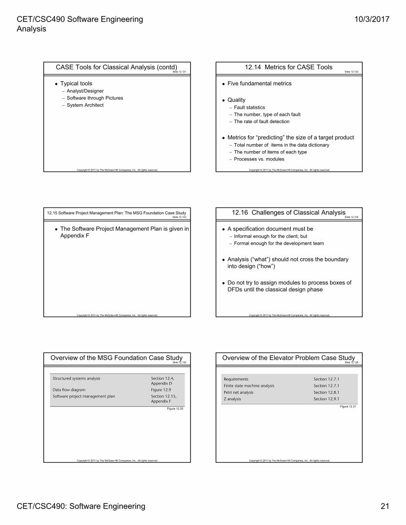
CASE Tools for Classical Analysis (contd)
Typical tools– Analyst/Designer
– Software through Pictures
– System Architect
Slide 12.122
Copyright © 2011 by The McGraw-Hill Companies, Inc. All rights reserved.
12.14 Metrics for CASE Tools
Five fundamental metrics
Quality– Fault statistics
– The number, type of each fault
– The rate of fault detection
Metrics for “predicting” the size of a target product– Total number of items in the data dictionary
– The number of items of each type
– Processes vs. modules
Slide 12.123
Copyright © 2011 by The McGraw-Hill Companies, Inc. All rights reserved.
12.15 Software Project Management Plan: The MSG Foundation Case Study
The Software Project Management Plan is given in Appendix F
Slide 12.124
Copyright © 2011 by The McGraw-Hill Companies, Inc. All rights reserved.
12.16 Challenges of Classical Analysis
A specification document must be– Informal enough for the client; but
– Formal enough for the development team
Analysis (“what”) should not cross the boundary into design (“how”)
Do not try to assign modules to process boxes of DFDs until the classical design phase
Slide 12.125
Copyright © 2011 by The McGraw-Hill Companies, Inc. All rights reserved.
Overview of the MSG Foundation Case Study
Figure 12.30
Slide 12.126
Copyright © 2011 by The McGraw-Hill Companies, Inc. All rights reserved.
Overview of the Elevator Problem Case Study
Figure 12.31