objectives - caribbean dialysisprinciplesofdialysis.weebly.com/uploads/5/6/1/3/5613613/2008cc... ·...
TRANSCRIPT

ObjectivesAfter completing this module, the learner will be able to:
1. Discuss the purpose of water treatment for dialysis.
2. List the components of a dialysis center’s water treatment system.
3. Discuss the advantages and disadvantages of water softeners, carbon tanks, reverse osmosis, deionization, and ultraviolet irradiation in the treatment of water for dialysis.
4. Describe the method for microbiological testing of the water treatment system.
5. Describe a typical water treatment monitoring schedule.
Water Treatment
226
IntroductionDialysate is a fluid used to help remove wastesfrom patients’ blood. Water is used to makedialysate, mix concentrate, and to flush out andreprocess dialyzers. If dialysis water hascontaminants (harmful substances), they mayenter the blood through the dialyzer and causedisease, injury, or even death to a patient.
Healthy people can handle some contaminantsin their drinking water; healthy kidneys removemost of them. People with failed kidneys do not have that protection. To be safe, water to be used for dialysis must pass through a watertreatment system—a series of devices, each of which takes out certain contaminants.
This module covers why and how water istreated before it is used for dialysis. It describesthe components of a water treatment system,how the system is monitored, and the commoncontaminants found in water.
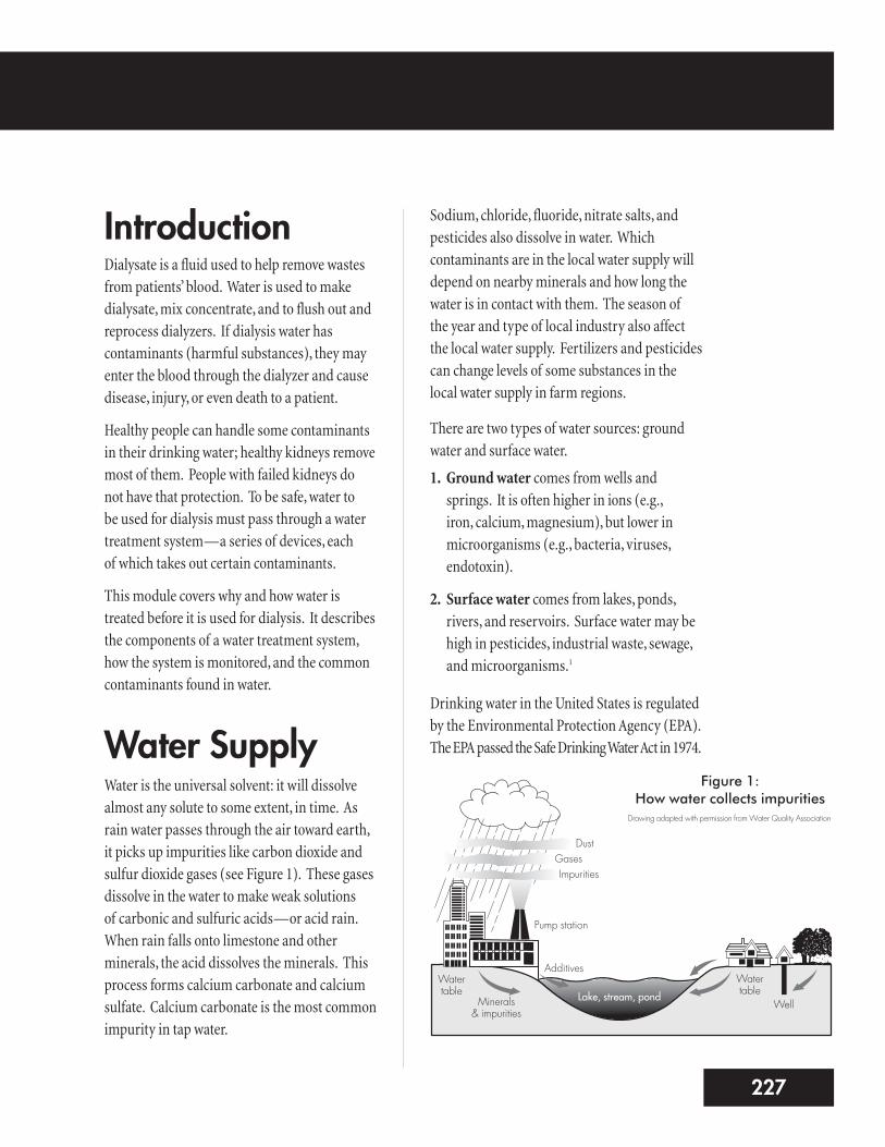
Water SupplyWater is the universal solvent: it will dissolvealmost any solute to some extent, in time. Asrain water passes through the air toward earth,it picks up impurities like carbon dioxide andsulfur dioxide gases (see Figure 1). These gasesdissolve in the water to make weak solutions of carbonic and sulfuric acids—or acid rain.When rain falls onto limestone and otherminerals, the acid dissolves the minerals. Thisprocess forms calcium carbonate and calciumsulfate. Calcium carbonate is the most commonimpurity in tap water.
Sodium, chloride, fluoride, nitrate salts, andpesticides also dissolve in water. Whichcontaminants are in the local water supply willdepend on nearby minerals and how long thewater is in contact with them. The season of the year and type of local industry also affectthe local water supply. Fertilizers and pesticidescan change levels of some substances in thelocal water supply in farm regions.
There are two types of water sources: groundwater and surface water.
1. Ground water comes from wells andsprings. It is often higher in ions (e.g., iron, calcium, magnesium), but lower inmicroorganisms (e.g., bacteria, viruses,endotoxin).
2. Surface water comes from lakes, ponds,rivers, and reservoirs. Surface water may behigh in pesticides, industrial waste, sewage,and microorganisms.1
Drinking water in the United States is regulatedby the Environmental Protection Agency (EPA).The EPA passed the Safe Drinking Water Act in 1974.
3227
Figure 1:How water collects impurities
Drawing adapted with permission from Water Quality Association
DustGasesImpurities
Pump station
Watertable
Minerals & impurities
AdditivesWatertable
WellLake, stream, pond
To be safe for the general public, drinking wateris treated to help prevent disease. Chloramine, a mix of chlorine and ammonia, is often used tokill bacteria. Fluoride is used in many places to prevent tooth decay. Alum, an aluminumcompound, may be used as a flocculent, whichremoves solid particles from the water. Somecities also raise water pH (acid/base indicator)to control the levels of metals that can leach(dissolve) out of pipes into the drinking water.1
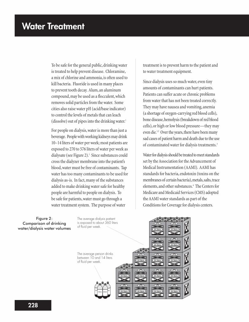
For people on dialysis, water is more than just abeverage. People with working kidneys may drink10–14 liters of water per week; most patients areexposed to 270 to 576 liters of water per week asdialysate (see Figure 2).1 Since substances couldcross the dialyzer membrane into the patient’sblood, water must be free of contaminants. Tapwater has too many contaminants to be used fordialysis as-is. In fact, many of the substancesadded to make drinking water safe for healthypeople are harmful to people on dialysis. To be safe for patients, water must go through awater treatment system. The purpose of water
treatment is to prevent harm to the patient andto water treatment equipment.
Since dialysis uses so much water, even tinyamounts of contaminants can hurt patients.Patients can suffer acute or chronic problemsfrom water that has not been treated correctly.They may have nausea and vomiting, anemia (a shortage of oxygen-carrying red blood cells),bone disease, hemolysis (breakdown of red bloodcells), or high or low blood pressure—they mayeven die.1,3 Over the years, there have been manysad cases of patient harm and death due to the useof contaminated water for dialysis treatments.3
Water for dialysis should be treated to meet standardsset by the Association for the Advancement ofMedical Instrumentation (AAMI). AAMI hasstandards for bacteria, endotoxin (toxins on themembranes of certain bacteria), metals, salts, traceelements, and other substances.4 The Centers forMedicare and Medicaid Services (CMS) adoptedthe AAMI water standards as part of theConditions for Coverage for dialysis centers.
Water Treatment
228
2 liters 2 liters 2 liters2 liters 2 liters 2 liters
2 liters 2 liters 2 liters2 liters 2 liters 2 liters24 liters
2 liters 2 liters 2 liters2 liters 2 liters 2 liters
2 liters 2 liters 2 liters2 liters 2 liters 2 liters24 liters
2 liters 2 liters 2 liters2 liters 2 liters 2 liters
2 liters 2 liters 2 liters2 liters 2 liters 2 liters24 liters
2 liters 2 liters 2 liters2 liters 2 liters 2 liters
2 liters 2 liters 2 liters2 liters 2 liters 2 liters24 liters
2 liters 2 liters 2 liters2 liters 2 liters 2 liters
2 liters 2 liters 2 liters2 liters 2 liters 2 liters24 liters
2 liters 2 liters 2 liters2 liters 2 liters 2 liters
2 liters 2 liters 2 liters2 liters 2 liters 2 liters24 liters
2 liters 2 liters 2 liters2 liters 2 liters 2 liters
2 liters 2 liters 2 liters2 liters 2 liters 2 liters24 liters
2 liters 2 liters 2 liters2 liters 2 liters 2 liters
2 liters 2 liters 2 liters2 liters 2 liters 2 liters24 liters
2 liters 2 liters 2 liters2 liters 2 liters 2 liters
2 liters 2 liters 2 liters2 liters 2 liters 2 liters24 liters
2 liters 2 liters 2 liters2 liters 2 liters 2 liters
2 liters 2 liters 2 liters2 liters 2 liters 2 liters24 liters
2 liters 2 liters 2 liters2 liters 2 liters 2 liters
2 liters 2 liters 2 liters2 liters 2 liters 2 liters24 liters
2 liters 2 liters 2 liters2 liters 2 liters 2 liters
2 liters 2 liters 2 liters2 liters 2 liters 2 liters24 liters
2 liters 2 liters 2 liters2 liters 2 liters 2 liters
2 liters 2 liters 2 liters2 liters 2 liters 2 liters24 liters
2 liters 2 liters 2 liters2 liters 2 liters 2 liters
2 liters 2 liters 2 liters2 liters 2 liters 2 liters24 liters
2 liters 2 liters 2 liters2 liters 2 liters 2 liters
2 liters 2 liters 2 liters2 liters 2 liters 2 liters24 liters
2 liters 2 liters 2 liters2 liters 2 liters
Figure 2:Comparison of drinking
water/dialysis water volumes
The average dialysis patient is exposed to about 360 liters of fluid per week.
The average person drinksbetween 10 and 14 litersof fluid per week.
AAMI standards cover all water and water-relatedequipment used for reprocessing dialyzers,mixing concentrates, and making dialysate.
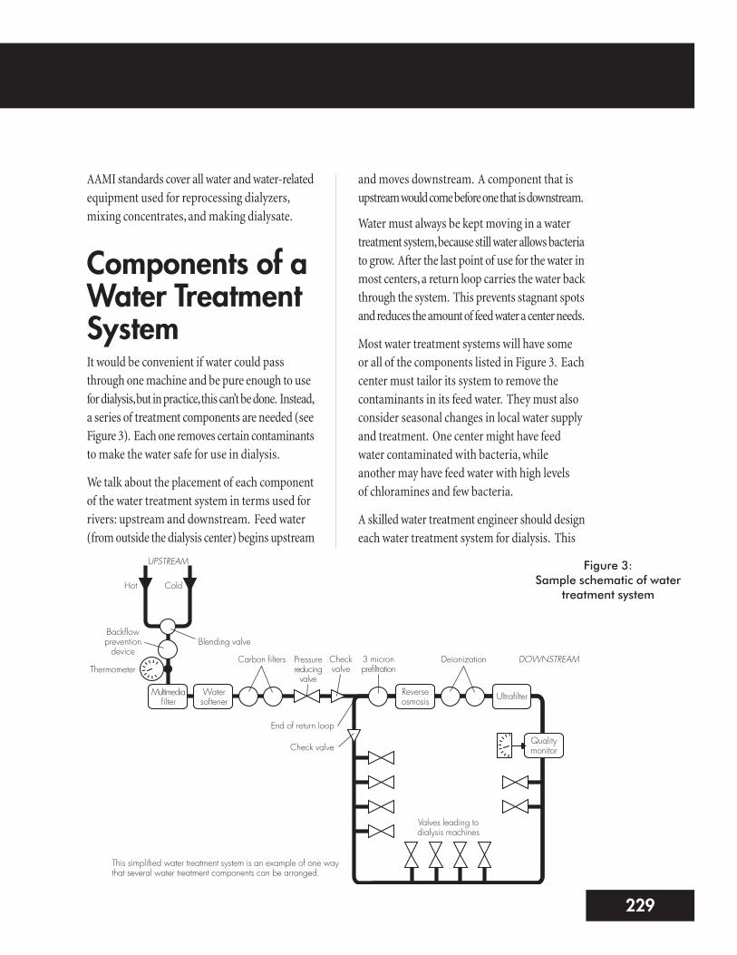
Components of aWater TreatmentSystemIt would be convenient if water could passthrough one machine and be pure enough to usefor dialysis, but in practice, this can’t be done. Instead,a series of treatment components are needed (seeFigure 3). Each one removes certain contaminantsto make the water safe for use in dialysis.
We talk about the placement of each componentof the water treatment system in terms used forrivers: upstream and downstream. Feed water(from outside the dialysis center) begins upstream
and moves downstream. A component that isupstream would come before one that is downstream.
Water must always be kept moving in a watertreatment system, because still water allows bacteriato grow. After the last point of use for the water inmost centers, a return loop carries the water backthrough the system. This prevents stagnant spotsand reduces the amount of feed water a center needs.
Most water treatment systems will have some or all of the components listed in Figure 3. Eachcenter must tailor its system to remove thecontaminants in its feed water. They must alsoconsider seasonal changes in local water supplyand treatment. One center might have feedwater contaminated with bacteria, whileanother may have feed water with high levels of chloramines and few bacteria.
A skilled water treatment engineer should designeach water treatment system for dialysis. This
5229
Figure 3:Sample schematic of water
treatment system
UPSTREAM
Hot
Thermometer
Backflowpreventiondevice
Blending valve
Cold
Carbon filters Pressurereducingvalve
Checkvalve
3 micronprefiltration
Deionization
Multimediafilter
Watersoftener
Reverseosmosis Ultrafilter
Qualitymonitor
DOWNSTREAM
Valves leading todialysis machines
End of return loop
Check valve
This simplified water treatment system is an example of one waythat several water treatment components can be arranged.
engineer must know the impact each componenthas on the other parts, on the product water, andon the patient. The number and order of devicescan be set up to suit the needs of any center.1
FEED WATERCOMPONENTS
Backflow Prevention DeviceA reduced-pressure, backflow prevention device isneeded for all water treatment systems; it stopswater from a center’s water treatment system fromflowing back into the feed water. This, in turn,keeps any contaminants taken out by the watertreatment system from getting into the feed water.1
Temperature Blending ValveThe temperature blending valve mixes hot andcold water to a standard 77°F. The temperaturemust stay at this level to prevent harm to patientsand damage to the reverse osmosis membranes(more on this later in the module). A decreasein temperature from 77°F will decrease the
efficiency of a reverse osmosis membrane.There is a 1.5% decrease for every 1°F drop intemperature. A temperature gauge is placeddownstream from the temperature blendingvalve as a monitor.1
Booster PumpThe water treatment system needs constantwater flow and pressure. If flow or pressuredrop from a center’s water source, a boosterpump may be used to increase them. Thebooster pump is placed downstream from thebackflow prevention device and temperatureblending valve. Pressure gauges are placedbefore and after the booster pump.1
PRETREATMENTCOMPONENTS
Chemical Injection SystemsThe ideal pH of the feed water should be5.0–8.5. If the pH is higher than 8.5, a chemicalinjection system may be used to inject a smallamount of hydrochloric or sulfuric acid into the feed water. This will lower the water’s pHlevel. Such systems may also be used to reducechloramines in feed water by injecting sodiummetabisulfite.1
Chemical injection systems have a reservoir tohold the chemicals, a metering pump, and amixing chamber in the feed water line. Thesystems must have a way to control the amountof chemicals added to the water.
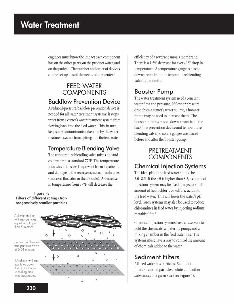
Sediment Filters All feed water has particles. Sediment filters strain out particles, solutes, and othersubstances of a given size (see Figure 4).
Water Treatment
230
Figure 4:Filters of different ratings trapprogressively smaller particles
A 5 micron filter will trap particlesequal to or largerthan 5 microns.
Submicron filters willtrap particles downto 0.01 micron.
Ultrafilters will trapparticles down to 0.01 microns,including mostmicroorganisms.

The multimedia filter is the most commonsediment filter (see Figure 5).1
Multimedia filters have layers of different-sizedrocks. Water can pass through the filter, butmost particles above a certain size are trapped.Each layer is finer than the one before, to trapsmaller and smaller particles. As particles arestrained out, the filter may clog. When thesystem is not in use, water should be sent fromthe bottom of the filter to the top to clean andremix the media. This is called backwashingand flushes particles out of the filter.1
Water SoftenerHard water has many minerals. A water softener(see Figure 6) can “soften” hard water by takingout some of the calcium and magnesium that formscale (solid particles that settle out of the water).Water softeners work by ion exchange—ions ofcalcium and magnesium are removed and tradedfor sodium ions, which form sodium chloride.
Ion exchange takes place in a “bed” of tinyround beads made of polystyrene resin. Theresin beads are coated with sodium chlorideions. The resin attracts positively charged ionsof calcium and magnesium from the hard water.It gives up sodium ions of equal charge. Whenthe resin is saturated with calcium and magnesium,it is exhausted, and must be regenerated(cleaned and saturated again with sodium).
Water softeners are regenerated by flushing theresin bed with water and then with brine (veryconcentrated saline). The resin beads exchangetheir calcium, magnesium, and other positivelycharged ions, and are again coated with sodiumions. The unwanted positive ions are thenrinsed to the drain.1
7231
Figure 5:Cartridge filter housing
Filter media
Feed waterTrapped sediment
particlesA sediment filter, such asthis one, acts as a sieve totrap particles of a certainmicron size. Feed waterenters the filter, passesthrough the filter media(where particles aretrapped), and exits thefilter.
Figure 6:Water softener
Drawing adapted from Keshaviah, Investigation of the Risks and Hazards Associated with Hemodialysis Devices
Inside a water softener, “hard water” mineral ions (calcium and magnesium, whichform scale) are traded for sodium ions in a process called ion exchange. A bed ofresin media beads attracts and holds calcium and magnesium ions, and releasessodium ions into the water. The water that results is called “soft.”
Underbedmedia
Resin bed
Salt pellets
Brine tank
Control assembly Drain line
OutletInlet
Most centers have permanent water softeners,with their own brine tanks. The brine tankholds salt pellets and water. The salt and watercreate the solution to regenerate the softener, socenters can regenerate their water softeners on-site. It is vital to prevent your water softenerfrom regenerating during dialysis. If this wereto happen, high levels of sodium could causethe reverse osmosis system to alarm because itcould not handle that much sodium. Othercenters have portable water softeners. These areregenerated off site by a vendor. Regenerationshould be done every day or every other day.1
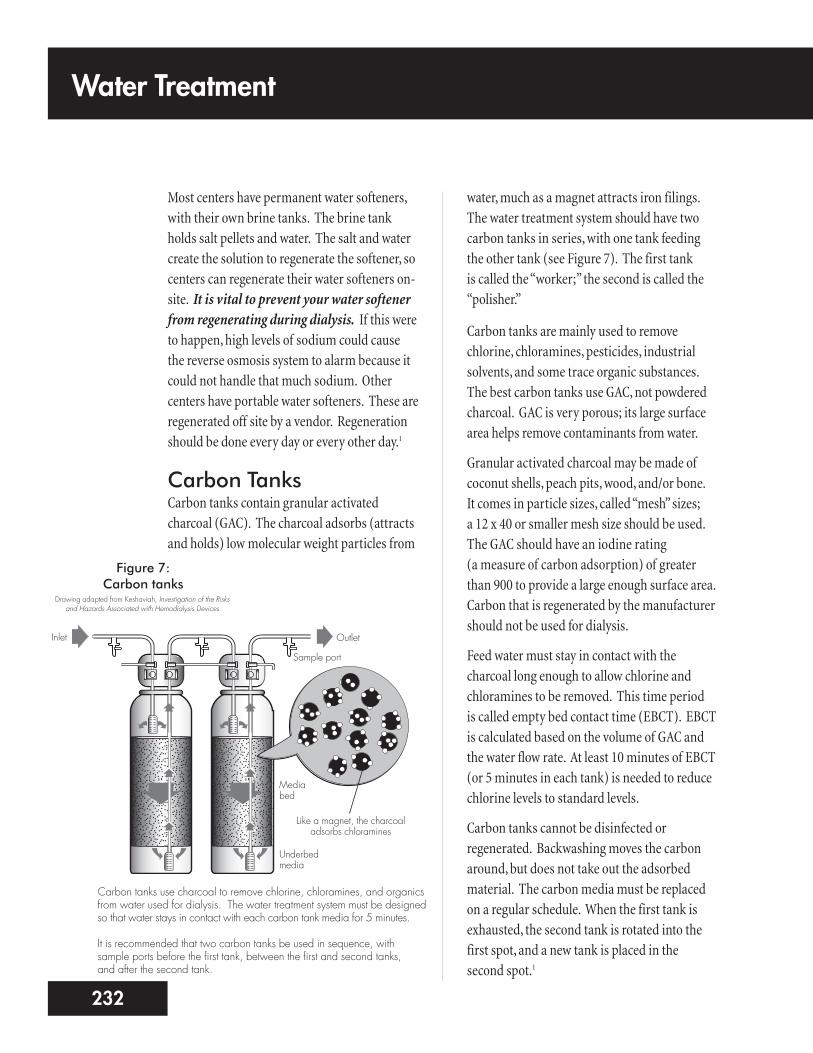
Carbon TanksCarbon tanks contain granular activatedcharcoal (GAC). The charcoal adsorbs (attractsand holds) low molecular weight particles from
water, much as a magnet attracts iron filings.The water treatment system should have twocarbon tanks in series, with one tank feedingthe other tank (see Figure 7). The first tank is called the “worker;” the second is called the“polisher.”
Carbon tanks are mainly used to removechlorine, chloramines, pesticides, industrialsolvents, and some trace organic substances.The best carbon tanks use GAC, not powderedcharcoal. GAC is very porous; its large surfacearea helps remove contaminants from water.
Granular activated charcoal may be made ofcoconut shells, peach pits, wood, and/or bone. It comes in particle sizes, called “mesh” sizes; a 12 x 40 or smaller mesh size should be used.The GAC should have an iodine rating (a measure of carbon adsorption) of greaterthan 900 to provide a large enough surface area.Carbon that is regenerated by the manufacturershould not be used for dialysis.
Feed water must stay in contact with thecharcoal long enough to allow chlorine andchloramines to be removed. This time period is called empty bed contact time (EBCT). EBCTis calculated based on the volume of GAC andthe water flow rate. At least 10 minutes of EBCT(or 5 minutes in each tank) is needed to reducechlorine levels to standard levels.
Carbon tanks cannot be disinfected orregenerated. Backwashing moves the carbonaround, but does not take out the adsorbedmaterial. The carbon media must be replacedon a regular schedule. When the first tank isexhausted, the second tank is rotated into thefirst spot, and a new tank is placed in the second spot.1
Water Treatment
232
Figure 7:Carbon tanks
Drawing adapted from Keshaviah, Investigation of the Risks and Hazards Associated with Hemodialysis Devices
Like a magnet, the charcoaladsorbs chloramines
Underbedmedia
Mediabed
Sample port
OutletInlet
Carbon tanks use charcoal to remove chlorine, chloramines, and organicsfrom water used for dialysis. The water treatment system must be designedso that water stays in contact with each carbon tank media for 5 minutes.
It is recommended that two carbon tanks be used in sequence, withsample ports before the first tank, between the first and second tanks, and after the second tank.

REVERSE OSMOSISPROCESS AND SYSTEM
Reverse osmosis (RO) is a way to remove solutes from a solution using a membrane andpressure. The RO system contains a waterpressure pump and a semipermeablemembrane. The RO system is the most fragileand costly part of the water treatment system.One of the tasks of the pretreatmentcomponents of the water treatment system is to protect the RO system from damage.
RO ProcessRO uses hydraulic pressure to remove solutes fromwater (see Figure 8). Osmosis is movement ofwater across a semipermeable membrane froman area of lesser solute concentration to an areaof greater solute concentration (see Module 3:Principles of Dialysis, to learn more aboutosmosis). The process goes on until the solute
levels on both sides of the membrane are equal.RO forces feed water through a membrane—leaving salts and other contaminants behind.The contaminants and some of the water (wastestream or reject stream) are sent to the drain or back to the feed side of the RO system. Thepurified water is used for dialysis.
RO SystemCartridge prefilterA filter is placed just before the RO to removecarbon fines, resin beads, and other debris.Gauges should be placed before and after theprefilter. Prefilters are low-cost and should bechanged on a regular basis.1
RO pump and motor assemblyThe RO pump is the loudest part of the watertreatment system. The pump is used to raisepressure across the RO membrane.
9233
Figure 8:Reverse osmosis
PressureOsmosis Reverse Osmosis
Feedwater
Pure productwater
Pure water
Concentrated salt solution
When a concentrated salt solution and pure water areseparated by a semipermeable membrane, pure water willmove across the membrane to dilute the salt water, in aprocess called osmosis. Osmosis will go on until theosmotic pressure is equalized by hydrostatic (hydraulic)pressure exerted by the rising level of concentrated solution.
If enough pressure is exerted on theconcentrated solution to overcome osmosis,reverse osmosis occurs. Pure water is forcedout of the concentrated solution.
Water Treatment
234
RO membranesThe membrane is the key part of the RO system.It filters out or rejects metals, salts, andchemicals, as well as bacteria, endotoxins, andviruses. RO can reject 95%–99% of chargedionic particles (e.g., aluminum). Organicmaterials (e.g., bacteria) are rejected if theirmolecular weight is greater than 200.
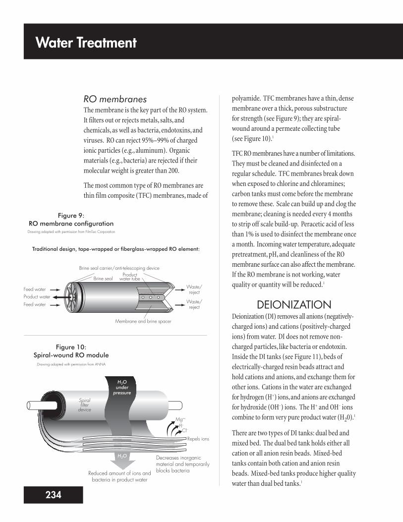
The most common type of RO membranes arethin film composite (TFC) membranes, made of
polyamide. TFC membranes have a thin, densemembrane over a thick, porous substructure for strength (see Figure 9); they are spiral-wound around a permeate collecting tube (see Figure 10).1
TFC RO membranes have a number of limitations.They must be cleaned and disinfected on aregular schedule. TFC membranes break downwhen exposed to chlorine and chloramines;carbon tanks must come before the membraneto remove these. Scale can build up and clog themembrane; cleaning is needed every 4 monthsto strip off scale build-up. Peracetic acid of lessthan 1% is used to disinfect the membrane oncea month. Incoming water temperature, adequatepretreatment, pH, and cleanliness of the ROmembrane surface can also affect the membrane.If the RO membrane is not working, waterquality or quantity will be reduced.1
DEIONIZATION Deionization (DI) removes all anions (negatively-charged ions) and cations (positively-chargedions) from water. DI does not remove non-charged particles, like bacteria or endotoxin.Inside the DI tanks (see Figure 11), beds ofelectrically-charged resin beads attract andhold cations and anions, and exchange them forother ions. Cations in the water are exchangedfor hydrogen (H+) ions, and anions are exchangedfor hydroxide (OH–) ions. The H+ and OH– ionscombine to form very pure product water (H20).
1
There are two types of DI tanks: dual bed andmixed bed. The dual bed tank holds either allcation or all anion resin beads. Mixed-bedtanks contain both cation and anion resinbeads. Mixed-bed tanks produce higher qualitywater than dual bed tanks.1
Figure 9:RO membrane configurationDrawing adapted with permission from FilmTec Corporation
Figure 10:Spiral-wound RO module
Membrane and brine spacer
Productwater tubeBrine seal
Brine seal carrier/anti-telescoping device
Waste/reject
Waste/reject
Feed water
Feed waterProduct water
Traditional design, tape-wrapped or fiberglass-wrapped RO element:
Spiral filter
device
H2O under
pressure
H2O
Repels ions
Mg++
Cl–Fl–
Drawing adapted with permission from ANNA
Decreases inorganicmaterial and temporarilyblocks bacteriaReduced amount of ions and
bacteria in product water

While DI is quite good at taking out unwantedions, there are some risks to using it:
1. First, if all the hydrogen and hydroxyl ions in aDI tank are exhausted (used up), the resin beadswill release the ions that they had removed.So, the treated water may be very acidic (lowpH) or alkaline (high pH), or may have highlevels of harmful chemicals.1 DI has causedmost of the water treatment related deaths inpatients.5 DI tanks should be sized for greaterthan the amount of water to be treated. Theymust be monitored all the time so they canbe exchanged before exhaustion occurs.1
2. Second, DI does not remove bacteria, and theresin bed can support the growth of bacteria.An ultrafilter, or other way to removebacteria and endotoxin, is needed after(downstream) the DI tank.1
3. Third, portable DI tanks are used in a centerbut regenerated off-site. It is vital to be surethat resins used for dialysis are not mixedwith industrial resins when the tanks areregenerated. Only medical or food-graderesins should be used for dialysis DI tanks.Industrial-grade resins may contain harmfulheavy metals and industrial solvents.1
4. Finally, a carbon filter should be placedupstream of the DI tanks to remove chlorine.Use of DI systems to treat water containingchlorine/chloramines generatesnitrosamines, which can cause cancer inpatients treated with the water.1
DI is usually an emergency backup to the ROsystem, and is rarely used as the primary watertreatment.1,4 Because of the risks, DI tanks used in dialysis must use a temperature-compensated resistivity meter with an alarm
that can be heard and seen in the patient carearea. The alarm goes off when the waterresistivity drops below 1 megohm/cm.
ULTRAVIOLET (UV)IRRADIATOR
The UV irradiator uses UV light, a form ofinvisible radiation, to destroy microorganisms.It works by changing the DNA (geneticmaterial) of the bacteria so they die or can’tmultiply.1 UV lights used to prevent bacterialgrowth have a light wavelength of 254nanometers. If the UV light is failing, bacteria
11235
Figure 11:Deionization tanks
Drawing adapted from Keshaviah, Investigation of the Risks and Hazards Associated with Hemodialysis Devices
OutletInlet
1 2 3
Cation bed Anion bed Mixed bed Mixed bed
A deionization (DI) tank, like a water softener, uses resin media beads for ionexchange.
The cation bed removes positively-charged ions and releases hydrogen (H+) ionsinto the water. The anion bed removes negatively-charged ions and releaseshydroxl (OH–) ions. (H+ and OH– ions combine to form H2O, pure water.) Themixed bed is used to remove any remaining ions so that water used for dialysis isfree of ions that could affect the conductivity of dialysate.
(1) “Light” resistivity indicator is lit at greater than 50,000 ohm/cm. (2) “Light” type resistivity indicator is lit at greater than 1 megohm/cm. (3) Temperaturecompensated resistivity monitor produces audible and visible alarm at less than 1 megohm/cm, and is a requirement per AAMI standards.

can become resistant to UV radiation, and may be able to multiply to harmful levels unlessother means are used to control them. UV light equipment uses a mercury vapor lampthat emits light at a certain wavelength, housedinside a quartz sleeve. Feed water flows over the quartz material and is exposed to the UVlight.
For the UV technique to work, the mercuryvapor lamps must be replaced according to themanufacturer’s instructions.4 The quartz sleevemust also be cleaned to stay clear so the water is exposed to the light. The flow of water mustalso be within the manufacturer’s standards.
Older systems require monitoring the numberof hours used and replacement parameters. In newer systems, the irradiator will have acalibrated UV intensity meter that delivers a minimum dose of radiant energy at 16milliwatt-sec/cm2, and sets off a visual alarmwhen a new bulb is needed.
The UV irradiator may also be placed with thepretreatment components, after the carbon
tanks. This will lower the bacteria levels goinginto the RO system.1
SUBMICRON AND ULTRAFILTERS
Submicron filters are membrane filters that reducethe level of bacteria in product water. Ultrafilters(see Figure 12) are membrane filters that removebacteria and endotoxin. The filters can becomecontaminated with bacteria, which can enterthe product water. Filters should be cleaned and disinfected or replaced when the pressuredifference between the inlet and outlet filtergauges is 10 pounds per square inch.2
DistributionSystemThere are two types of RO distribution systems:direct feed and indirect feed.
n The direct feed system delivers productwater directly from the RO system to theproduct water loop for distribution. Unusedproduct water is sent back to the RO system.
n The indirect feed system uses a storage tankto hold product water and send it to theproduct water loop for use. Unused productwater is returned to the storage tank.1
WATER STORAGEThe water storage tank should have a tight-fittinglid and a cone- or bowl-shaped bottom to ensurecomplete emptying of the tank and easy disinfectingand rinsing. Product water does not contain chlorineor chloramines to prevent the growth of bacteria.The tank needs a recirculation pump, and shouldbe cleaned and disinfected on a regular basis.1
Water Treatment
236
Figure 12:Ultrafilter
Membrane housingSolutes are trapped by tinypores in the filter membrane
An ultrafilter is a cartridge housing a semipermeable membrane filter. The membrane removessubmicron (very small) solutes, as well as endotoxins and other organic material.

WATER DISTRIBUTIONPIPING SYSTEMS
A continuous loop is the recommended designfor a water distribution piping system. Productwater goes to a storage tank or the RO system tosave water. The loop should not have dead endsor multiple branches, as these raise the risk ofcontamination. To reduce bacterial growth, thewater flow velocity through the distribution systemshould be kept at a minimum of 3 feet per secondfor an indirect feed and 1.5 feet per second for adirect feed system. The most common materialused in piping systems is polyvinyl chloride (PVC).1
Disinfection ofWater TreatmentSystemsWater treatment systems need to stay as freefrom contaminants as possible. Biofilm—slimemade by microorganisms—is a major problemfor water treatment systems. Once biofilmstarts to form, it is almost impossible to remove.The entire water treatment system may need to be replaced if biofilm forms.1
The most common type of water treatmentsystem disinfection is chemical (e.g., bleach).Ozone and heat can also be used.
Monitoring a WaterTreatment SystemWater treatment systems used in dialysis are a key part of the overall care received by people
on dialysis. They can also be one of the greatesthazards to patients if they are not workingproperly.
Water treatment monitoring is an area ofconcern and a chance for quality improvementacross the nation. The only way to know if yourcenter’s system is working properly is to set upand follow an effective monitoring program.Each component must be checked to be sure itis working properly (see Figure 13 on page 238).If conditions change (such as feed water beingtreated differently by your town), you may needto test more often or change the water treatmentsystem.
All dialysis centers should keep in close contactwith the local water treatment plant. Each centershould send a letter to the plant at least once a year. The letter will remind the plant that adialysis center is present, and that the center willneed updates on the status of water treatment.If water treatment in the area changes, toomuch of a substance is present, water mains are flushed, or other events related to the watersupply occur, the plant needs to alert the center.
Monitoring of the SystemComponents
TEMPERATURE BLENDING VALVE
To protect the RO membrane and maintain an adequate flow of product water, feed watershould be kept at 77°F–82°F (25°C–28°C). If the temperature varies, the amount of
13237

product water will vary as well because if the feedwater is too hot, it can destroy an RO membrane.
The temperature blending valve should bechecked each day by measuring the
temperature after the valve. The temperatureshould be within the set range, and should not change much from day to day.2
Water Treatment
238
Mon Tues Wed Thu Fri SatDate
Gauge ReadingsPress. Gauge #1 (psi) (Pre-Mixbed)
- Mixed BedPress. Gauge #2 (psi) (Pre-Softener)
- SoftenerPress. Gauge #3 (psi) (Pre-Carb1)
- Carbon Tank #1Press. Gauge #4 (psi) (Pre-Carb2)
- Carbon Tank #2Softener Timer CheckTemperature (°F)Press. Gauge #5 (psi) (Pre-Filter)Press. Gauge #6 (psi) (Post-Filter)
- RO PrefilterFeed Water TDSProduct Water TDSPercent RejectionFeed FlowPermeate FlowFeed PressurePermeate PressureWater TestsPost-Softener Hardness #1Post-Softener Hardness #2
Logged By (initials):
Chloramines Tests (<0.1 mg/L)
Before 1st patient shift Before 2nd patient shift Before 3rd patient shift
Audit (initials):
P∆
P∆
P∆
P∆
P∆
Figure 13:Example of a water treatment system logTable adapted with permission from AAMI WATER TREATMENT SYSTEM LOG

BACKFLOW PREVENTION DEVICE
To keep water from flowing backward into theincoming water supply, most cities require thata backflow prevention device must be installedat the start of the water treatment system. Themain problem with these devices is that theymay reduce water flow and pressure. They mustbe tested once a year for proper functioning bysomeone who is licensed to test them.
When the device is installed, if both prepressure andpostpressure can be checked, there should not be adrop of greater than 10 pounds per square inch (psi)from the normal operating pressure.2 If you can onlymeasure postpressure, make sure there is enoughpressure and flow. Watch for pressure change overtime to see if the device is plugging up. The correctpressure level will vary with each system—youwill have to establish a baseline and thenmonitor for changes. On average, a large RO willneed about 30 psi at 10–12 gallons per minute.
DEPTH FILTRATIONFilters are prone to clogging as they trap particles,which reduces the flow of water. All filtersshould be checked each day by measuringpressure before and after the filter at normaloperating flow rates. If the difference in thesetwo pressures, or “delta pressure,” is greater than10 psi more than it was when the filter was new,the filter will need to be replaced or backflushed.If a filter comes with a backflush timer, checkthe timer setting for correct time; be sure it willonly backflush when the center is closed.
WATER SOFTENERSWater softeners should be monitored bymeasuring water hardness post-softener at the start
and end of each day. Hardness should not exceed1 grain per gallon (gpg), which equals 17.24 partsper million (ppm). There should be enough saltin the brine tank for regeneration. If the salt levelis too high, a “salt bridge” may occur, where salthardens at the top and looks full—even thoughthere is no salt underneath. The regenerationtimer should be checked for correct time, andbe set to regenerate when the center is closed.5
CARBON TANKSOne of the most vital patient safety tasks eachday is checking the carbon tanks for chlorineand chloramines. Each tank must have enoughcarbon to adsorb the chlorine and chloraminesin the amount of time the water is flowingthrough it. Water must touch the carbon for atleast 5 minutes of empty bed contact time(EBCT) in each tank, for a total of 10 minutes for the worker and polisher tanks.
EBCT is calculated using the formula: EBCT=V/Q,where V = the volume of carbon (in cubic feet) andQ = the water flow rate, in gallons per minute (gpm).To calculate the volume of carbon needed, usethe formula: V=(Q x EBCT) / 7.48 (this is thenumber of gallons in one cubic foot of water).1,2
For example, if you have a flow rate of 10 gpm,and you want an EBCT of 5 minutes, yourcalculation would be:V = (Q x EBCT) / 7.48
V = (10 x 5) / 7.48
V = 6.69
Therefore, you need a 6.69 cubic foot carbontank for each working and polishing tank.
The water system must be working for at least15–20 minutes before you take your first test. If you take your sample when you start up the
15239
system, you will be testing water that has beenin the tank overnight. This will not give you arepresentative sample of the carbon tank’scapability at normal flow rates.2
RO DEVICE (OPERATING PARAMETERS)Each RO device will have its own parameters totell you if it is working correctly. Water pressureand flow rates are measured in several places.Incoming water pressure needs to be enough to maintain flow through the RO device (this isusually 10 gpm at 30–40 psi, but will vary witheach system). Pump pressure is monitored, asthis is what pushes water through themembrane. The pressure of the product wateris also monitored, and it will vary greatlydepending on whether it is a direct or indirect(holding tank) feed system.2
Water flow is also measured in several placesusing flow meters. Product flow tells you howmuch purified water is getting through themembrane. Waste flow tells you how muchreject water is being flushed down the drain.Direct systems often measure the amount ofproduct water that is recirculated through thesystem to blend with the incoming water.
RO operating parameters should be checkedeach day for flow and pressure at various sites in the system. Pressure and flow in an ROsystem are interrelated. For example, if youreduce the RO pump pressure, product waterflow will drop and so will waste water flow. Ifthe product water flow drops without a changein pump pressure, the RO membrane may beclogging up. A change in the delta pressurebetween the pump and reject pressures canmean fouled or torn membranes. So, you willneed to know the appropriate baseline valuesfor all pressures and flows, and check out anydeviations. Analyze the trends to see even smallchanges over time.2
Water Treatment
240
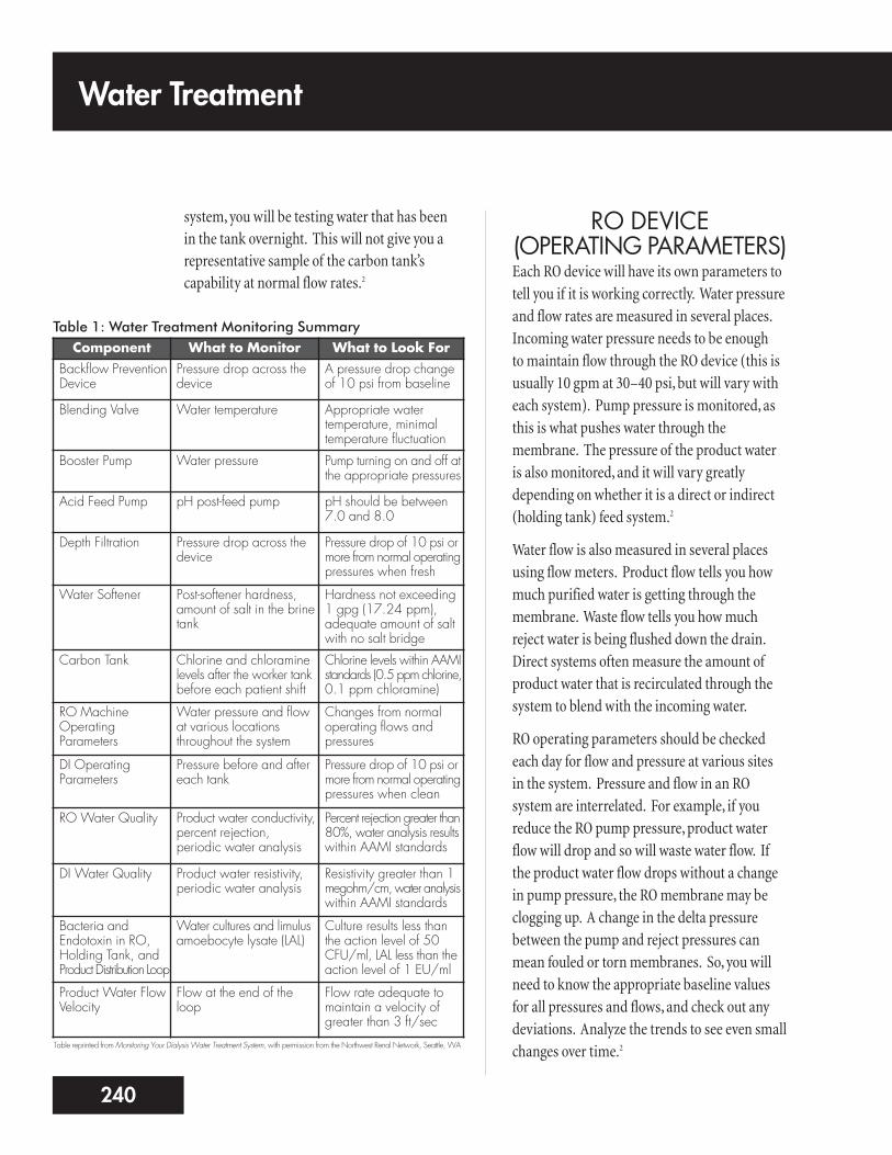
Table 1: Water Treatment Monitoring SummaryComponent What to Monitor What to Look For
Backflow PreventionDevice
Pressure drop across thedevice
A pressure drop changeof 10 psi from baseline
Blending Valve Water temperature Appropriate watertemperature, minimaltemperature fluctuation
Booster Pump Water pressure Pump turning on and off atthe appropriate pressures
Acid Feed Pump pH post-feed pump pH should be between7.0 and 8.0
Depth Filtration Pressure drop across thedevice
Pressure drop of 10 psi ormore from normal operatingpressures when fresh
Water Softener Post-softener hardness,amount of salt in the brinetank
Hardness not exceeding1 gpg (17.24 ppm),adequate amount of saltwith no salt bridge
Carbon Tank Chlorine and chloraminelevels after the worker tankbefore each patient shift
Chlorine levels within AAMIstandards (0.5 ppm chlorine,0.1 ppm chloramine)
RO MachineOperatingParameters
Water pressure and flowat various locationsthroughout the system
Changes from normaloperating flows andpressures
DI OperatingParameters
Pressure before and aftereach tank
Pressure drop of 10 psi ormore from normal operatingpressures when clean
RO Water Quality Product water conductivity,percent rejection,periodic water analysis
Percent rejection greater than80%, water analysis resultswithin AAMI standards
DI Water Quality Product water resistivity,periodic water analysis
Resistivity greater than 1megohm/cm, water analysiswithin AAMI standards
Bacteria andEndotoxin in RO,Holding Tank, andProduct Distribution Loop
Water cultures and limulusamoebocyte lysate (LAL)
Culture results less thanthe action level of 50CFU/ml, LAL less than theaction level of 1 EU/ml
Product Water FlowVelocity
Flow at the end of theloop
Flow rate adequate tomaintain a velocity ofgreater than 3 ft/sec
Table reprinted from Monitoring Your Dialysis Water Treatment System, with permission from the Northwest Renal Network, Seattle, WA

DI SYSTEMS (OPERATING PARAMETERS)DI tanks work by flowing water past smallbeads of resin treated with hydrogen andhydroxyl. DI itself has no moving parts, so themonitoring is simple and straightforward.
DI tanks should be monitored each day bymeasuring pressure before and after the tanks(see Table 1). When newly installed, thereshould not be a pressure drop greater than 10 psi from the normal operating pressure.2
WATER QUALITY A chemical analysis of your feed water shouldbe done periodically (see Appendix: WaterQuality Testing Chart). This will tell you aboutthe contaminants in the incoming water, andensure that the water treatment system will beable to reduce those contaminants to AAMIlevels. AAMI requires testing each year for thecontaminants in Table 2.1
Each day, water quality is also tested indirectly.This is done by checking conductivity for ROsand resistivity for DIs. Conductivity tells youthe level of total dissolved solids (TDS) in thewater in parts per million (ppm). By using the “percent rejection” formula: [1-(outputconductivity / input conductivity)] x 100, you can learn how much of a given solute isremoved by the RO membrane. For example,input conductivity is 100 ppm, and outputconductivity is 8 ppm. Enter into the formula:
[1-(8/100)] x 100
= (1-0.08) x 100
= 0.92 x 100
Therefore, you have a 92% rejection of totaldissolved solids.
The conductivity monitor should compensatefor temperature to give a consistent reading.The alarm should be set at a level of percentrejection that assures AAMI quality water. Thislevel will depend on your raw water analysis.
Because DI water is more pure than RO water, itsconductivity is too low to check accurately. So, wemonitor the final product water for resistance to theflow of electricity. This is the inverse, or opposite, ofconductivity. The acceptable limit of resistivity is
17241
Contaminant Suggested Maximum Level(mg/L)
Aluminum 0.01
Antimony 0.006
Arsenic, lead, silver Each 0.005
Beryllium 0.0004
Cadmium 0.001
Calcium 2.0 (0.1 mEq/L)
Chloramines 0.1
Chlorine (free) 0.5
Chromium 0.014
Copper, barium, zinc Each 0.1
Fluoride 0.2
Magnesium 4.0 (0.3 mEq/L)
Mercury 0.0002
Nitrates 2.0
Potassium 8.0 (0.2 mEq/L)
Selenium 0.09
Sodium* 70.0 (3.0 mEq/L)
Sulfate 100.0
Thallium 0.002
Table 2: AAMI Standards for Chemical Contaminants in Hemodialysis Water4
*230 mg/L (10 mEq/L) where sodium concentration of the concentrate has been reduced tocompensate for excess sodium in the water, as long as conductivity of the water is beingcontinuously monitored

greater than 1 megohm/cm resistance. You willneed to understand how the monitor on yourcenter’s DI system works, as they can vary. Mostoften, the indicators are simply LEDs that tellwater quality.
Water quality monitoring should be donecontinuously. Audible and visual alarms mustbe able to be heard and seen in the patient carearea. The percent rejection of an RO systemshould be maintained at a level that will assureAAMI quality water (>90%). Resistivity of DIwater should be greater than 1 megohm/cm.4,5
MICROBIOLOGICALTESTING
Contamination of water by microorganisms is aserious health concern for patients on dialysis.High levels of bacteria and/or endotoxin canharm patients by causing pyrogenic (fever)reactions.
AAMI recommends testing the components of your center’s water treatment system forbacteria and endotoxin at least once a month;more often if problems occur. Water samplesshould be taken in the worst case scenario. Thismeans cultures should be done just beforedisinfection of the system.4
You must collect water samples the right way fortesting to be accurate. Even small amounts ofdisinfectant can keep bacteria from growingduring a culture. To avoid contaminating awater sample, never clean the sample ports witha disinfectant. If a center insists on disinfectingthe ports, it should use alcohol only and allow itto evaporate fully before drawing the culturesample.4 Run water for one minute before youcollect the sample in a sterile container.
Test:
n Water used to make reprocessing chemicals
n Water used to rinse and clean dialyzers
n Water from a storage tank, if one is used
n Water leaving the RO unit (and/or deionizer,if used)
n Water at the start, middle, and end of thedistribution loop
n Water used to make dialysate (tested at thepoint it enters the dialysis machine)
BacteriaSome bacteria help humans, while others(pathogens) cause disease. Bacteria that areharmless on the skin’s surface may becomepathogens if they enter the blood. Gram-negative bacteria turn pink and Gram-positivebacteria turn purple, when using Gram’s stain.These bacteria form biofilm and can cling tosurfaces like dialysate jugs, pipes, tanks, or feedhoses. Biofilm protects the bacteria fromdisinfectants, making them hard to remove.
With the right pH, food, and a warmtemperature, bacteria can multiply very quickly.If there is a tear in the dialyzer membrane,bacteria can enter the patient’s blood, causingsepsis (blood poisoning). Bacteria can alsobreak down into substances that come intoindirect contact with the patient’s bloodthrough the membrane—even if it is not torn.When these substances reach the patient, theymay cause a pyrogenic reaction: chills, fever,hypotension (low blood pressure), nausea,vomiting, and myalgia (muscle pains).
Bacteria in dialysis water must not exceed theAAMI standard of 200 colony forming units
Water Treatment
242

(CFU) (measure of the number of livingbacteria). The AAMI action level for bacteria inwater for dialysate is 50 CFU/mL. For ultrapure(sterile, non-pyrogenic) dialysate, the levelshould be less than 0.1 CFU/mL. An “actionlevel” is the point when measures must be takento meet AAMI standards.4 The center mustshow that some action (e.g., disinfection,retesting) has been taken to lower the bacteriacount if the action level is reached.4
EndotoxinEndotoxin is part of the cell wall of some Gram-negative bacteria. When these bacteria die,endotoxin is released. Endotoxin can causepyrogenic reactions in dialysis patients.6
Endotoxin is not alive; it can’t be killed and it is very hard to remove. The endotoxin levelshould be less than 2 EU/mL (endotoxinunits/ml) with an action level of 1 EU/mL. Tobe considered ultrapure dialysate, the endotoxinlevel should be less than 0.03 EU/mL.4
Caring for SamplesSamples for bacteria testing should beprocessed within 1–2 hours or refrigeratedimmediately and processed within 24 hours.Bacteria samples should be tested using themembrane filter technique (Millipore®
Samplers) or the spread plate technique.Tryptic soy agar (TSA) is the medium of choicefor testing water and dialysate samples.1 Do notuse the calibrated loop, or blood or chocolateagar. Calibrated loops have too small a samplesize (either 0.01 or 0.001 cc). Blood andchocolate agars are too nutrient rich for water-borne bacteria; this could cause them to dierather than multiply. Test for endotoxin with a limulus amoebocyte lysate (LAL) test.4
Preventing Bacterial GrowthAAMI recommends that water in the productwater distribution loop have a flow rate of atleast 3 feet per second. This high flow rateprovides friction along the wall of the tubing,which keeps bacteria from growing onto thesides of the pipe. To calculate the flow rate, youmust install a flow meter at the end of the loop,and know the size of piping used. Water flowingat 10 gpm will move much faster through a 1/2-inch pipe than it will through a 1-inchpipe.2 A regular program of disinfection (at least monthly) is also needed to preventbacterial growth.5
ChemicalMonitoringA chemical analysis of the water is required atleast once a year. The sample should be drawnfrom a sample port immediately after the RO or DI system.2 The water treatment systemmust operate within the AAMI standards at all times. AAMI has set the highest allowablelevels of contaminants that can be in theproduct water (see Table 2 on page 241).1
CHLORINE ANDCHLORAMINES
Chlorine and chloramine are used in city watertreatment to protect our drinking water frombacterial growth. The chloramine “family”includes chlorine gas (often used to killbacteria, fungi, and viruses in drinking water),and chlorine bleach (sodium hypochlorite). Chloramines are made by mixing chlorine andammonia, and are used by cities when a longer-
19243
acting chlorine is needed. Chloramines can alsobe formed in nature, when chlorine combineswith organic material.
Chloramines are strong oxidants: substances thatreact with oxygen to destroy cell walls—includingred blood cells. Patients exposed to high levels ofchloramines may develop methemoglobinemia(loss of oxygen-carrying ability of the red bloodcells), hemolysis (breakdown of red blood cells),and hemolytic anemia (a shortage of red bloodcells due to red blood cell breakdown).
The most widely used ways to test water forchlorine/chloramines are colorimeters, colorcomparators, and test strips. Because these testresults are read by comparing colors, the persondoing them must pass a color blindness test.
The limit for chlorine is 0.5 ppm, and the limitfor chloramines is 0.1 ppm. There is no directtest for chloramines, so to measure chloraminesyou must do two tests: one for total chlorine,and one for free chlorine. The chloramine levelis the difference between the two test results.For example, your measured total chlorine is 1.2 ppm and your measured free chlorine is 0.8 ppm:
1.2 – 0.8 = 0.4 ppm
Therefore your chloramine level is 0.4 ppm.
It is okay, per AAMI, to test just for total chlorineif the test is sensitive enough to detect low levelsand if action is taken for any results greater than0.1 ppm. If you have a zero reading for totalchlorine, there can’t be any chloramines present.2
The importance of careful testing for chlorine/chloramines cannot be stressed enough.Patients exposed to water containing thesecontaminants will be injured and could die.
SODIUM AND POTASSIUMSodium and potassium are electrolytes thatmust be kept at very precise levels in the blood.Electrolytes send electrical signals along the nervesto the muscles—including the heart. Sodiumand potassium are added in precise levels todialysate to make sure that blood levels of theelectrolytes are kept within the normal range.
AAMI recommends that water used for dialysiscontain no more than 70 mg/L (3.0 mEq/L) ofsodium and 8 mg/L (0.2 mEq/L) of potassium.4
Sodium and potassium are removed by RO and/or DI.
CALCIUM ANDMAGNESIUM
Hard water contains calcium and magnesium ascalcium carbonate and magnesium carbonate.If too much of these minerals reach patients,the result may be “hard water syndrome.” Thiscan cause nausea, vomiting, muscle weakness,severe headaches, skin flushing, and hyper orhypotension. Calcium crystals can also depositin the soft tissues of the patient’s body overtime, causing pain, injury, or death.
Too much calcium or magnesium can also causescale to form, which can clog equipment anddamage the RO membrane. The AAMI standardsare no more than 2 mg/L (0.1 mEq/L) of calciumand 4 mg/L (0.3 mEq/L) of magnesium.4
FLUORIDEFluorine makes up part of our bones and teeth.A salt of fluorine, called fluoride, is added todrinking water in many areas (up to a level of 1.2 mg/L) as a public health measure to help prevent tooth decay. Levels of fluoride in drinking water may vary from day to day.
Water Treatment
244

Water treatment helps protect dialysis patientsfrom accidental exposure to high levels.
Many dialysis patients are prone to bonedisease. Some patients who have long-termexposure to fluoridated water developosteosclerosis (hardening of bone and/or bonemarrow). Other symptoms of too muchfluoride include nausea, vomiting, muscletwitching, hypotension, and seizures.
AAMI recommends a fluoride limit in dialysiswater of no more than 0.2 mg/L.3 Fluoride isremoved by RO and/or DI.
NITRATESNitrates can be found in harmful amounts in waterfrom some wells, due to bacteria or farm fertilizers.Nitrates are dangerous to patients because theycan keep red blood cells from using oxygen. Thisis called methemoglobinemia; a patient with thiscondition will have cyanosis—bluish skin, lips, gums, and fingernail beds—from the lack of oxygen.They may also have hypotension and nausea.
AAMI recommends a nitrate limit in dialysiswater of no more than 2 mg/L.4 Nitrates areremoved by RO and/or DI.
SULFATESSulfates (salts or esters of sulfuric acid) in levelsgreater than 200 mg/L can cause nausea, vomiting,and can be linked with metabolic acidosis (highblood acid levels). AAMI recommends a sulfatelimit in water used for dialysis of no more than100 mg/L.4 Sulfates are removed by RO and/or DI.
ALUMINUMAluminum, a common metal in the earth, mayoccur in the local water supply. Or, it may be
added (as alum) to make water clearer byremoving algae, sediment, and silt. In healthypeople, only small amounts of aluminum areabsorbed from the diet; the kidneys remove the excess.
When the kidneys fail, aluminum can build upin the brain and bones. Damage to the nervoussystem and fatal encephalopathy (a defect inbrain function) can occur. This is called dialysisdementia; symptoms may include confusion,loss of short-term memory, personality changes,speech problems, muscle spasms, hallucinations,seizures, and intellectual impairment. Long-term exposure to high levels of aluminum hasalso been linked with aluminum-related bonedisease (ARBD). ARBD can cause bone pain,muscle weakness, and fractures.
Dialysis water is a key source of toxic aluminumfor patients. Ionized (electrically-charged)aluminum can cross the dialyzer membraneand move into the patient’s blood.
Dialysis equipment, too, may be a source ofaluminum. In 1992, a pump containingaluminum was placed on an acid distributionsystem. Three patients died and others hadhigh aluminum levels.5 Centers should check the design of their water treatment, concentrate,and dialysate delivery systems, and testpatients’ blood aluminum levels.
Because aluminum builds up in the bodies of dialysis patients, AAMI recommends thataluminum levels in dialysis water be very low—no more than 0.1 mg/L. Aluminum can beremoved by RO and/or DI. Since aluminumlevels in local water supplies can vary with theseason, experts suggest testing water used fordialysis for aluminum more than once a year.7,8
21245

COPPER AND ZINCWater, especially acidic water, can leach copperout of plumbing pipes. The use of galvanizediron in the water treatment or distributionsystem can cause high zinc levels in the water.
In the patient’s body, too much copper cancause nausea, vomiting, headaches, and chills.More severe problems can include painfulpancreatitis (inflammation of the pancreas),metabolic acidosis, liver damage, and fatalhemolysis (breakdown of red blood cells). High zinc levels can cause nausea, vomiting,fever, and anemia.
AAMI recommends an upper limit for copperand zinc in dialysis water of no higher than 0.10 mg/L.4 Copper and zinc can be removed by RO and/or DI.
ARSENIC, BARIUM,CADMIUM, CHROMIUM,
LEAD, MERCURY, AND SELENIUM
Each of these trace metals has been restricted to very low levels by the EPA Safe DrinkingWater Act as summarized in Table 3.9 AAMI
standards for a number of contaminants areshown in Table 2 on page 241. Arsenic, barium,cadmium, chromium, lead, mercury, andselenium can be removed by RO and/or DI.
PatientMonitoringAs you’ve learned in this module, water qualityis monitored to protect patients and to protectequipment so it can protect patients. Failure ofone or more parts of the water treatment systemcan cause serious illness—even death—inpatients who are exposed to untreated orimproperly treated water. Patient monitoring of water quality should include:
1. Routine blood monitoring – High levels of toxic substances in patients’ blood (e.g.,aluminum), or the presence of substancesthat are not normally found in the blood,need further study. For example, do anumber of patients have the same findings?Trouble with anemia management inpatients could be related to contaminants in the water. However, most problems withwater treatment are not found in routineblood tests.
2. Monitoring patient symptoms – Duringdialysis, patients may report acute (suddenonset) symptoms. There are many causes forsome symptoms, like hypotension—andwater quality may be one of them. If two ormore patients have similar symptoms at thesame time, there may be a problem with awater treatment or delivery system (if acentral dialysate delivery system is being
Water Treatment
246
Contaminant Maximum Contaminant Level (mg/L)
Arsenic 0.010
Barium 2.0
Cadmium 0.005
Chromium 0.10
Lead 0.015
Mercury 0.002
Selenium 0.05
Table 3: EPA National Primary Drinking Water Standards9

used.) If a water quality problem issuspected, the dialysis machine should be put in bypass, and the water treatmentsystem quickly evaluated. In some cases,treatment will be discontinued. Table 4 lists some patient symptoms and the watercontaminants that may cause them.7
ConclusionWhen maintained and monitored properly, awell-designed water treatment system canreduce the types and amounts of contaminants.Understanding the reasons for water treatmentand the type of system in your center is crucial.As a dialysis technician, you play a vital role inmaking sure that dialysis water is safe forpatient use. Every time you check a monitor,record a meter value on a log sheet, or test acomponent of your center’s water treatmentsystem for bacterial contamination, you arehelping to ensure safe, quality patient care.
23247
Sign or Symptom Possible Water Contaminant-related Cause
Anemia Aluminum, chloramines, copper, zinc
Bone Disease Aluminum, fluoride
Hemolysis Chloramines, copper, nitrates
Hypotension Bacteria, endotoxin, nitrates, calcium, magnesium
Metabolic acidosis Low pH, sulfates
Muscle weakness Calcium, magnesium
Nausea and vomiting Bacteria, calcium, copper, endotoxin, low pH, magnesium, nitrates, sulfates, zinc
Neurological deterioration Aluminum
Fever, chills Bacteria, endotoxin, copper, zinc
Severe headaches Copper
Hypertension Calcium, magnesium, copper, sodium
Liver damage Copper
Table 4: Symptoms Potentially Related to Water Contamination7
Water Treatment
248
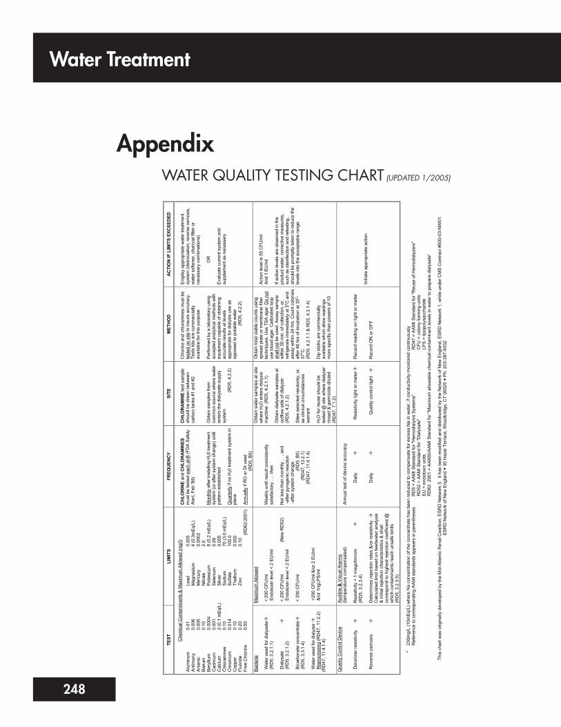
AppendixWATER QUALITY TESTING CHART (UPDATED 1/2005)
TEST
LI
MIT
S FR
EQU
ENC
Y SI
TE
MET
HO
D
AC
TIO
N IF
LIM
ITS
EXC
EED
ED
Che
mic
al C
onta
min
ants
& M
axim
um A
llow
ed (m
g/l)
Alum
inum
An
timon
y Ar
seni
c Ba
rium
Be
rylliu
m
Cad
miu
m
Cal
cium
C
hlor
amin
es
Chr
omiu
m
Cop
per
Fluo
ride
Free
Chl
orin
e
0.01
0.
006
0.00
5 0.
10
0.00
04
0.00
1 2
(0.1
mEq
/L)
0.10
0.
014
0.10
0.
20
0.50
Lea
d M
agne
sium
M
ercu
ry
Nitr
ate
Pot
assi
um
Sel
eniu
m
Silv
er
Sod
ium
S
ulfa
te
Tha
llium
Z
inc
0.00
5 4
(0.3
mEq
/L)
0.00
02
2.0
8 (0
.2 m
Eq/L
) 0.
09
0.00
5 70
(3.0
mEq
/L)
100.
0 0.
002
0.10
(RD
62:2
001)
CH
LOR
INE
and
CH
LOR
AM
INES
m
ust b
e te
sted
eac
h sh
ift (F
DA
Safe
ty
Aler
t, Fe
b '8
8)
Mon
thly
afte
r ins
tallin
g H
20 tr
eatm
ent
syst
em (o
r afte
r sys
tem
cha
nge)
unt
il pa
ttern
est
ablis
hed
Qua
rterly
if n
o H
20 tr
eatm
ent s
yste
m in
pl
ace
Annu
ally
if R
O o
r DI u
sed
(R
D5,
B5)
CH
LOR
AM
INE
test
sam
ple
shou
ld b
e dr
awn
betw
een
carb
on ta
nks
#1 a
nd #
2 O
btai
n sa
mpl
es fr
om
com
mon
sou
rce
whe
re w
ater
en
ters
the
dial
ysat
e su
pply
sy
stem
(RD
5, 4
.2.2
)
Chl
orin
e an
d ch
lora
min
es m
ust b
e te
sted
on
site
to in
sure
acc
urac
y.
Test
s ki
ts a
re c
omm
erci
ally
av
aila
ble
for t
his
purp
ose
Perfo
rmed
by
a la
bora
tory
usi
ng
acce
pted
ana
lytic
al m
etho
ds w
ith
equi
pmen
t cap
able
of o
btai
ning
ac
cura
te re
sults
at l
evel
s ap
prop
riate
for d
ialy
sis
use
as
oppo
sed
to p
otab
le w
ater
(RD
5, 4
.2.2
)
Empl
oy a
ppro
pria
te w
ater
trea
tmen
t sy
stem
(dei
oniz
atio
n, re
vers
e os
mos
is,
wat
er s
ofte
ner,
char
coal
filte
r or
nece
ssar
y co
mbi
natio
ns)
O
R
Eval
uate
cur
rent
sys
tem
and
su
pple
men
t as
nece
ssar
y
Bact
eria
W
ater
use
d fo
r dia
lysa
te
(R
D5,
3.2
.1.1
) D
ialy
sate
(R
D5,
3.2
.1.2
) B
icar
bona
te c
once
ntra
te
(R
D5,
3.3
.1.4
) W
ater
use
d fo
r dia
lyze
r
Rep
roce
ssin
g (R
D47
, 11.
2.2)
(RD
47, 1
1.4.
1.4)
Max
imum
Allo
wed
<
200
CFU
/ml
End
otox
in le
vel <
2 E
U/m
l <
200
CFU
/ml
(New
RD
52)
End
otox
in le
vel <
2 E
U/m
l <
200
CFU
/ml
<20
0 C
FU/m
l &/o
r 2 E
U/m
l &
/or 1
ngLP
S/m
l
Wee
kly
until
resu
lt co
nsis
tent
ly
satis
fact
ory
. . .
then
N
ot le
ss th
an m
onth
ly .
. . a
nd
- afte
r pyr
ogen
ic re
actio
n - a
fter s
yste
m c
hang
e
(RD
5, B
5)
(R
D47
, 13.
2.1)
(RD
47, 1
1.4.
1.4)
Obt
ain
wat
er s
ampl
es a
t site
w
here
H2O
ent
ers
dial
ysis
m
achi
ne (
RD
5, 4
.2.1
.1)
Obt
ain
dial
ysat
e sa
mpl
es a
t ou
tflow
sid
e of
dia
lyze
r (R
D5,
4.2
.1.2
) Si
tes
sele
cted
rand
omly
, or,
as c
linic
al c
ircum
stan
ces
war
rant
H
2O fo
r reu
se s
houl
d be
te
sted
@ s
ite w
here
dia
lyze
r rin
sed
& ge
rmic
ide
dilu
ted
(RD
47, 7
.1.2
)
Obt
ain
tota
l via
ble
coun
ts u
sing
sp
read
pla
te o
r mem
bran
e fil
ter
tech
niqu
es. U
se T
SA a
gar.
Do
not
use
bloo
d ag
ar. C
alib
rate
d lo
op
shal
l not
be
used
. Ass
ay s
ampl
e w
ithin
30
min
. of c
olle
ctio
n, o
r, re
frige
rate
imm
edia
tely
at 5
o C a
nd
assa
y w
ithin
24
hrs.
Cou
nt c
olon
ies
afte
r 48
hrs
of in
cuba
tion
at 3
5o -37
o C.
(RD
5, 4
.2.1
.1 &
RD
5, 4
.3.1
.4)
Dip
stic
ks a
re c
omm
erci
ally
av
aila
ble
whi
ch a
llow
read
ings
m
ore
spec
ific
than
pow
ers
of 1
0
Actio
n le
vel i
s 50
CFU
/ml
And
1 EU
/ml
If ac
tion
leve
ls a
re o
bser
ved
in th
e pr
oduc
t wat
er, c
orre
ctiv
e m
easu
res,
su
ch a
s di
sinf
ectio
n an
d re
test
ing,
sh
ould
be
prom
ptly
take
n to
redu
ce th
e le
vels
into
the
acce
ptab
le ra
nge.
Qua
lity
Con
trol D
evic
e D
eion
izer
resi
stiv
ity
R
ever
se o
smos
is
Aud
ible
& V
isua
l Ala
rms
(tem
pera
ture
com
pens
ated
) R
esis
tivity
< 1
meg
ohm
/cm
(RD
5, 3
.2.3
.4)
Det
erm
ines
reje
ctio
n ra
tes
&/o
r res
istiv
ity.
C
alcu
late
d lim
it ba
sed
on fe
edw
ater
ana
lysi
s &
initi
al re
ject
ion
char
acte
ristic
s &
sha
ll co
rres
pond
to h
ighe
st re
ject
ion
coef
ficie
nt @
w
hich
con
tam
inan
ts re
ach
unsa
fe li
mits
(R
D5,
3.2
.3.5
)
Ann
ual t
est o
f dev
ice
accu
racy
Dai
ly
Dai
ly
R
esis
tivity
ligh
t or m
eter
Qua
lity
cont
rol l
ight
Rec
ord
read
ing
on li
ght o
r met
er
Rec
ord
ON
or O
FF
Initi
ate
appr
opria
te a
ctio
n
*
230m
g/L
(10m
Eq/
L) w
here
Na
conc
entra
tion
of th
e co
ncen
trate
has
bee
n re
duce
d to
com
pens
ate
for e
xces
s N
a in
wat
er, i
f con
duct
ivity
mon
itore
d co
ntin
uous
ly
Ref
eren
ce to
cor
resp
ondi
ng A
AM
I sta
ndar
ds a
ppea
rs in
par
enth
eses
.
R
D5
= A
AM
I Sta
ndar
d fo
r "H
emod
ialy
sis
Sys
tem
s"
R
D47
= A
AMI S
tand
ard
for "
Reu
se o
f Hem
odia
lyze
rs"
RD
52 =
AAM
I Sta
ndar
d fo
r "D
ialy
sate
"
C
FU =
col
ony
form
ing
units
EU
= e
ndot
oxin
uni
ts
LPS
= li
popo
lysa
ccha
ride
R
D62
: 200
1 =
AA
NS
I/AA
MI S
tand
ard
for "
Max
imum
allo
wab
le c
hem
ical
con
tam
inan
t lev
els
in w
ater
to p
repa
re d
ialy
sate
”
ES
RD
Net
wor
k of
New
Eng
land
3
0 H
azel
Ter
race
, Woo
dbrid
ge, C
T 06
525
Ph:
203
-387
-933
2 Th
is c
hart
was
orig
inal
ly d
evel
oped
by
the
Mid
-Atla
ntic
Ren
al C
oalit
ion,
ES
RD
Net
wor
k 5.
It h
as b
een
mod
ified
and
dis
tribu
ted
by th
e N
etw
ork
of N
ew E
ngla
nd, E
SR
D N
etw
ork
1, w
hile
und
er C
MS
Con
tract
#50
0-03
-NW
01.

25249
References1. Amato RL: Water treatment for hemodialysis: updated to include the latest AAMI Standards forDialysate (RD52:2004). Nephrol Nurs J 32(2):151-69, 2005.
2. Curtis J, Byers L, Roshto B, Roshto B (Monitoring Committee): Monitoring Your Dialysis WaterTreatment System. Seattle, WA, Northwest Renal Network, 2005.
3. Levin R: The role of water in dialysis: why does it need to be more than “clean”? Nephrol NewsIssues 15(2):21-22, 2001.
4. Association for the Advancement of Medical Instrumentation: Dialysate for Hemodialysis(ANSI/AAMI RD52:2004). Arlington, VA, American National Standard, 2004.
5. Amato RL: The best of bloopers and blunders, myths and misconceptions. Nephrol News Issues15(4):51-53, 2001.
6. Dorland WAN: Dorland’s Illustrated Medical Dictionary. Philadelphia, PA, W.B. Saunders Co.,2003.
7. Luehmann DA, Keshaviah PR, Ward RA, Klein E, Thomas A: Risks and hazards associated withinadequately treated water and current water quality standards, in: A Manual on WaterTreatment for Hemodialysis (HHS Publication FDA 89-4234). Rockville, MD, U.S. Dept. ofHealth and Human Services, Public Health Service/Food and Drug Administration/Center forDevices and Radiological Health, 2005, pp 3-15.
8. ESRD Network of New England: Water quality testing chart (1/2005). Available at:www.esrdnetworks.org/networks/net1/watertreat.pdf. Accessed April 2006.
9. Environmental Protection Agency: National Primary Drinking Water Standards (2003).Available at: www.epa.gov/safewater/mcl. Accessed July 25, 2005.