official work order network engineering team background: the company has recently undergone an...
TRANSCRIPT
Networking SIMPaul Dalli
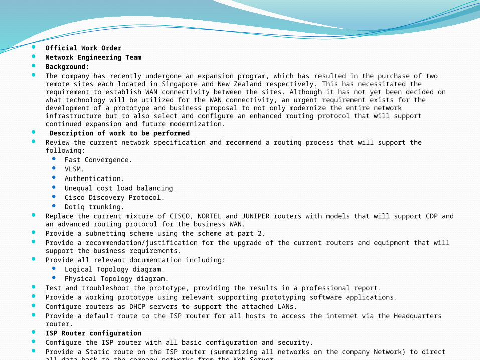
Official Work Order Network Engineering Team Background: The company has recently undergone an expansion program, which has resulted in the purchase of two remote sites
each located in Singapore and New Zealand respectively. This has necessitated the requirement to establish WAN connectivity between the sites. Although it has not yet been decided on what technology will be utilized for the WAN connectivity, an urgent requirement exists for the development of a prototype and business proposal to not only modernize the entire network infrastructure but to also select and configure an enhanced routing protocol that will support continued expansion and future modernization.
Description of work to be performed Review the current network specification and recommend a routing process that will support the following:
Fast Convergence. VLSM. Authentication. Unequal cost load balancing. Cisco Discovery Protocol. Dot1q trunking.
Replace the current mixture of CISCO, NORTEL and JUNIPER routers with models that will support CDP and an advanced routing protocol for the business WAN.
Provide a subnetting scheme using the scheme at part 2. Provide a recommendation/justification for the upgrade of the current routers and equipment that will support the
business requirements. Provide all relevant documentation including:
Logical Topology diagram. Physical Topology diagram.
Test and troubleshoot the prototype, providing the results in a professional report. Provide a working prototype using relevant supporting prototyping software applications. Configure routers as DHCP servers to support the attached LANs. Provide a default route to the ISP router for all hosts to access the internet via the Headquarters router. ISP Router configuration Configure the ISP router with all basic configuration and security. Provide a Static route on the ISP router (summarizing all networks on the company Network) to direct all data back to
the company networks from the Web Server. The network address between the ISP and headquarters router is 189.54.69.265/30. The network between the ISP and Web server is 10.0.0.0/30.

Technical solution
Why?> Setting up new expansion for business
How is it a business solution?
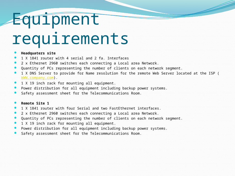
Equipment requirements Headquaters site 1 X 1841 router with 4 serial and 2 fa. Interfaces 2 x Ethernet 2960 switches each connecting a Local area Network. Quantity of PCs representing the number of clients on each network segment. 1 X DNS Server to provide for Name resolution for the remote Web Server located at the ISP (
WWW.company.com). 1 X 19 inch rack for mounting all equipment. Power distribution for all equipment including backup power systems. Safety assessment sheet for the Telecommunications Room.
Remote Site 1 1 X 1841 router with four Serial and two FastEthernet interfaces. 2 x Ethernet 2960 switches each connecting a Local area Network. Quantity of PCs representing the number of clients on each network segment. 1 X 19 inch rack for mounting all equipment. Power distribution for all equipment including backup power systems. Safety assessment sheet for the Telecommunications Room.
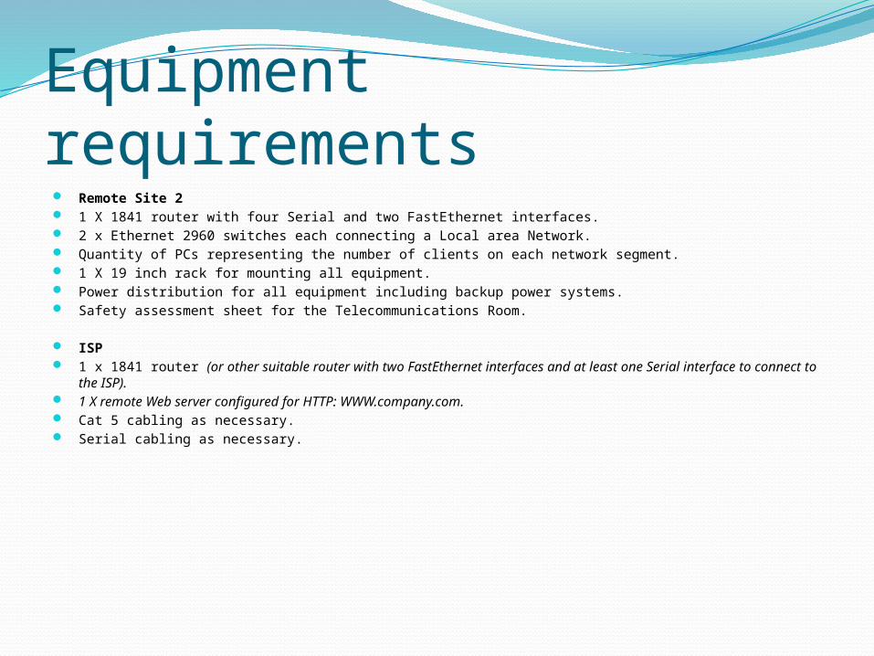
Equipment requirements Remote Site 2 1 X 1841 router with four Serial and two FastEthernet interfaces. 2 x Ethernet 2960 switches each connecting a Local area Network. Quantity of PCs representing the number of clients on each network segment. 1 X 19 inch rack for mounting all equipment. Power distribution for all equipment including backup power systems. Safety assessment sheet for the Telecommunications Room.
ISP 1 x 1841 router (or other suitable router with two FastEthernet interfaces and at least one Serial interface to
connect to the ISP). 1 X remote Web server configured for HTTP: WWW.company.com. Cat 5 cabling as necessary. Serial cabling as necessary.

Subnet scheme Host Requirements:
Headquarters 90 hosts 60 hosts
Remote 1 60 hosts 30 hosts
Remote 2 128 hosts 60 hosts
Connections Between remote sites and Headquarters You will have to allow for the most efficient sub-networks to interconnect the sites as follows:
Both Remote1 and Remote2 will connect via WAN connection to Headquarters As a redundancy Remote1 will also connect to Remote 2 via a WAN connection
The network address between the ISP and headquarters router is
189.54.69.264/30 The network between the ISP and Web server is 10.0.0.0/30
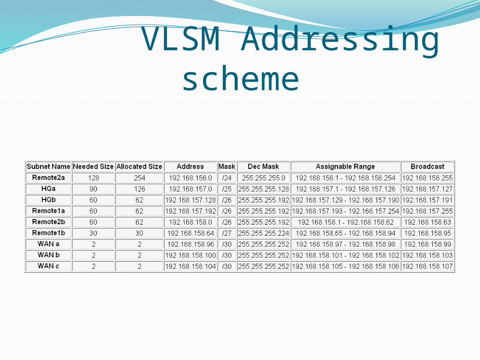
VLSM Addressing scheme
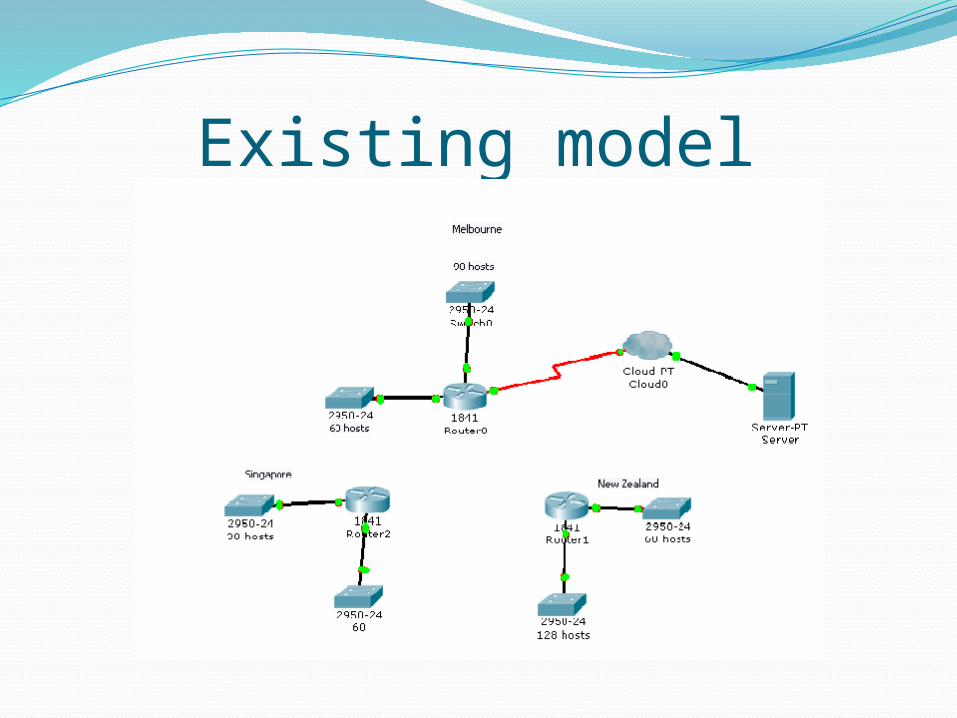
Existing model
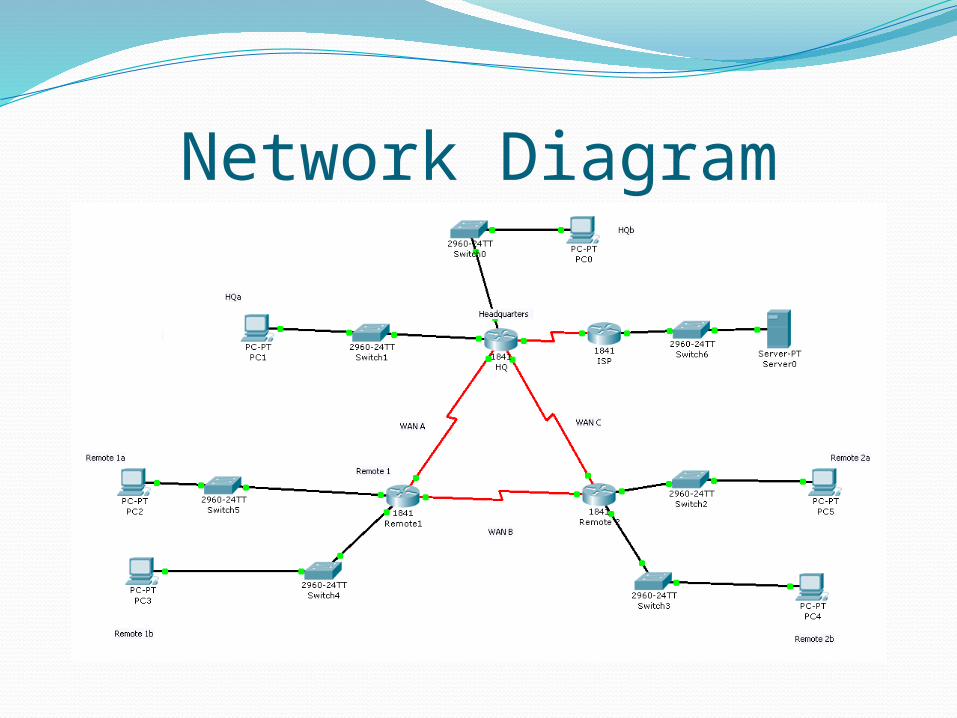
Network Diagram

Physical Diagram
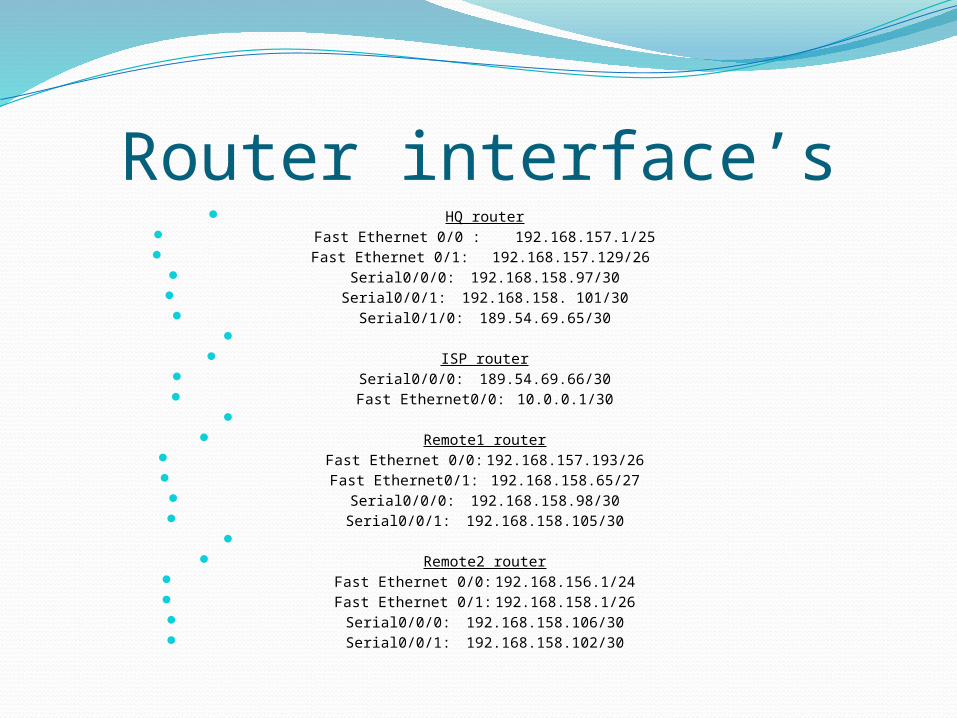
Router interface’s HQ router
Fast Ethernet 0/0 : 192.168.157.1/25 Fast Ethernet 0/1: 192.168.157.129/26
Serial0/0/0: 192.168.158.97/30 Serial0/0/1: 192.168.158. 101/30 Serial0/1/0: 189.54.69.65/30
ISP router
Serial0/0/0: 189.54.69.66/30 Fast Ethernet0/0: 10.0.0.1/30
Remote1 router
Fast Ethernet 0/0: 192.168.157.193/26 Fast Ethernet0/1: 192.168.158.65/27 Serial0/0/0: 192.168.158.98/30 Serial0/0/1: 192.168.158.105/30
Remote2 router
Fast Ethernet 0/0: 192.168.156.1/24 Fast Ethernet 0/1: 192.168.158.1/26 Serial0/0/0: 192.168.158.106/30 Serial0/0/1: 192.168.158.102/30
Lan Switching and WirelessAim:• Configure Cisco 1841 router as r”outer on a stick”• Configure switch security and remote configuration via telnet• Configure all interfaces and trunk ports• Configure VTP servers and clients• Configure VLAN’s on switches• Configure RSTP• Configure inter-vlan routing
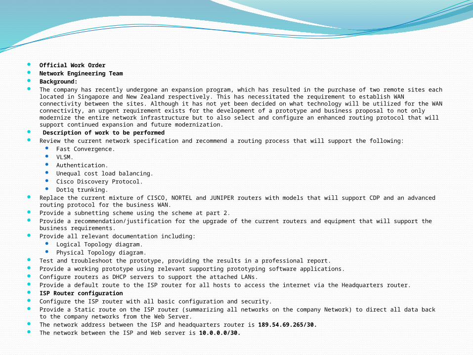
Official Work Order Network Engineering Team Background: The company has recently undergone an expansion program, which has resulted in the purchase of two remote sites each located
in Singapore and New Zealand respectively. This has necessitated the requirement to establish WAN connectivity between the sites. Although it has not yet been decided on what technology will be utilized for the WAN connectivity, an urgent requirement exists for the development of a prototype and business proposal to not only modernize the entire network infrastructure but to also select and configure an enhanced routing protocol that will support continued expansion and future modernization.
Description of work to be performed Review the current network specification and recommend a routing process that will support the following:
Fast Convergence. VLSM. Authentication. Unequal cost load balancing. Cisco Discovery Protocol. Dot1q trunking.
Replace the current mixture of CISCO, NORTEL and JUNIPER routers with models that will support CDP and an advanced routing protocol for the business WAN.
Provide a subnetting scheme using the scheme at part 2. Provide a recommendation/justification for the upgrade of the current routers and equipment that will support the business
requirements. Provide all relevant documentation including:
Logical Topology diagram. Physical Topology diagram.
Test and troubleshoot the prototype, providing the results in a professional report. Provide a working prototype using relevant supporting prototyping software applications. Configure routers as DHCP servers to support the attached LANs. Provide a default route to the ISP router for all hosts to access the internet via the Headquarters router. ISP Router configuration Configure the ISP router with all basic configuration and security. Provide a Static route on the ISP router (summarizing all networks on the company Network) to direct all data back to the company
networks from the Web Server. The network address between the ISP and headquarters router is 189.54.69.265/30. The network between the ISP and Web server is 10.0.0.0/30.
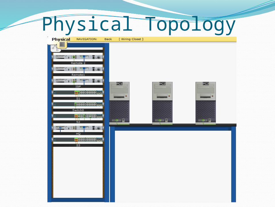
Physical Topology

Remote2
S1 VTP server
Logical Topology
PC3

S2 VLAN Switch
ISP Router
S3 Backup Root-Bridge
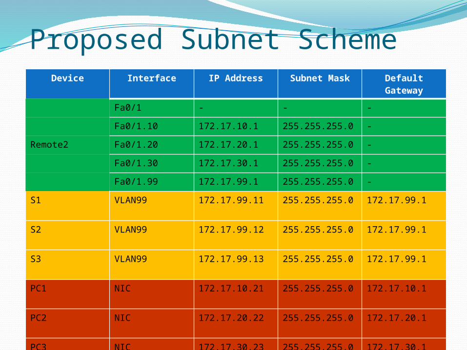
Proposed Subnet SchemeDevice Interface IP Address Subnet Mask Default
Gateway
Fa0/1 - - -
Fa0/1.10 172.17.10.1 255.255.255.0 -
Remote2 Fa0/1.20 172.17.20.1 255.255.255.0 -
Fa0/1.30 172.17.30.1 255.255.255.0 -
Fa0/1.99 172.17.99.1 255.255.255.0 -
S1 VLAN99 172.17.99.11 255.255.255.0 172.17.99.1
S2 VLAN99 172.17.99.12 255.255.255.0 172.17.99.1
S3 VLAN99 172.17.99.13 255.255.255.0 172.17.99.1
PC1 NIC 172.17.10.21 255.255.255.0 172.17.10.1
PC2 NIC 172.17.20.22 255.255.255.0 172.17.20.1
PC3 NIC 172.17.30.23 255.255.255.0 172.17.30.1