omnilink control panel quadro di comando omnilink · note: you can select the desired language...
TRANSCRIPT

QUADRO DI COMANDO OMNILINK
USO E MANUTENZIONE
OMNILINK CONTROL PANEL
OWNER MANUAL

_00 3
Tab. 1.1
Tab. 1.2
C
E
B
A
D
F
ED005303XXX0
OMNILINK CONTROL PANEL
POS. DESCRIPTIONA Panel ignition switch with key switchB Engine on/off push buttonC Engine rpm indicatorD Engine data or errors displayE Engine data or errors push buttonF Maintenance errors reset push button
POS. DESCRIPTION
Coolant temperature (°C)
Oil pressure (bar)
Battery voltage (V)
1 Component description
Tab. 1.1 shows the control panel components.
Tab. 1.2 shows data that can be consulted on display D by pressing push button E.
POS. DESCRIPTION
Total and partial hours of operation (h) - To reset partial hours, simultaneously
press push buttons E and F for 3 seconds
Hours left for maintenance (h)
Backlighting adjustment - Press push button E for 3 seconds - Press push button E to decrease
brightness or F to increase it
Important• Connect to http://iservice.lombardini.it > KDI KOHLER DIESEL section > login as a guest "Enter as a guest" > "TECHNICAL DOCUMENTATION" > select "KDI 1903 M-MP" or "KDI 2504 M-MP" and download the latest version of this manual onto your device.
NOTE: you can select the desired language before downloading the manual, as shown in the figure below.
TRANSLATED FROM THE ORIGINAL MANUAL IN ITALIAN LANGUAGE.
Data reported in this issue can be modified at any time by Lombardini Marine.
Drafting body
Code document
Code document Edition Revision Date
issueDate
Review Written by Endorsed
DICOM/ATLO ED005303xxx0 51463 1° 00 05/2016 05/2016

_00 _004 5
Tab. 2.1
Tab. 3.1
E D
F
ED005303XXX0 ED005303XXX0
OMNILINK CONTROL PANEL OMNILINK CONTROL PANEL
AMBIENT TEMPERATURE TIME≤ -20°C 2 minutes
from -20° C to -10°C 1 minutesfrom -10° C to -5° C 30 secondsfrom -5° C to 5° C 20 seconds
≥ 5° C 15 seconds
2 Starting and turning off
2.1 Starting
1 - Check the level of the engine oil, fuel and coolant and fill if necessary (Par. 4.5 and Par. 4.6).
2 - Put the ignition key in the ignition switch.
3 - Tun the key to 1 position.
4 - Press the Start push button for it to start automatically.
Important• RPM reading delay is normal.• If engine does not start after two attempts see the engine owner manual to find the cause.
2.2 After starting
Warning• Make sure that all the warning lights on the control panel are off when the engine is running.
• Check for any leakages from the pipes on first start-up
1 - Run at minimum speed for a few minutes according to Tab.2.1.
2.3 Turning off
1 - Do not turn off the engine with a full load or when it is running at the maximum rotation speed. Leave it running at idle speed without a load for approximately 1 minute.
2 - Press the Stop push button (the engine turns off) and turn the key to position 0.
3 Error signals on the control panel
Tab. 3.1 shows the errors that can be generated on the control panel.
Besides visual signals, acoustic errors are also transmitted from the panel.
Any errors disappear automatically once the anomaly has been solved.
(*1) - A maintenance service does not automatically carry out a reset; it must be reset manually, as follows:
1 - Press the E push button until the maintenance service page (Service h) is displayed on the screen D.
2 - Simultaneously press push buttons E and F for 10 secs. for screen D to reset the hours until the next maintenance.
POS. DESCRIPTION
Engine oil pressure low
High coolant temperature
Glow Plug or Glow Plug control unit failure
Disabled alternator (with engine rpm < 850 rpm)
Maintenance service (*1)
Insufficient battery voltage (flashing display with battery < 9 V)
NOTE: Contact Lombardini Marine authorized workshop for error signals not shown in Tab. 3.1.
_00 3
Tab. 1.1
Tab. 1.2
C
E
B
A
D
F
ED005303XXX0
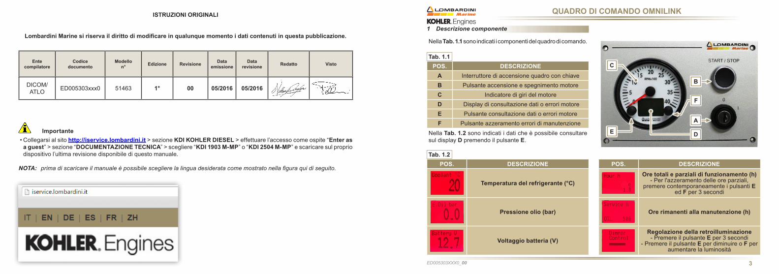
QUADRO DI COMANDO OMNILINK
POS. DESCRIZIONEA Interruttore di accensione quadro con chiaveB Pulsante accensione e spegnimento motoreC Indicatore di giri del motoreD Display di consultazione dati o errori motoreE Pulsante consultazione dati o errori motoreF Pulsante azzeramento errori di manutenzione
POS. DESCRIZIONE
Temperatura del refrigerante (°C)
Pressione olio (bar)
Voltaggio batteria (V)
1 Descrizione componente
Nella Tab. 1.1 sono indicati i componenti del quadro di comando.
Nella Tab. 1.2 sono indicati i dati che è possibile consultare sul display D premendo il pulsante E.
POS. DESCRIZIONE
Ore totali e parziali di funzionamento (h)- Per l'azzeramento delle ore parziali,
premere contemporaneamente i pulsanti E ed F per 3 secondi
Ore rimanenti alla manutenzione (h)
Regolazione della retroilluminazione- Premere il pulsante E per 3 secondi
- Premere il pulsante E per diminuire o F per aumentare la luminosità
Importante• Collegarsi al sito http://iservice.lombardini.it > sezione KDI KOHLER DIESEL > effettuare l’accesso come ospite “Enter as a guest” > sezione “DOCUMENTAZIONE TECNICA” > scegliere “KDI 1903 M-MP” o “KDI 2504 M-MP” e scaricare sul proprio dispositivo l’ultima revisione disponibile di questo manuale.
NOTA: prima di scaricare il manuale è possibile scegliere la lingua desiderata come mostrato nella figura qui di seguito.
ISTRUZIONI ORIGINALI
Lombardini Marine si riserva il diritto di modificare in qualunque momento i dati contenuti in questa pubblicazione.
Ente compilatore
Codice documento
Modellon° Edizione Revisione Data
emissioneData
revisione Redatto Visto
DICOM/ATLO ED005303xxx0 51463 1° 00 05/2016 05/2016

_00 _004 5
Tab. 2.1
Tab. 3.1
E D
F
ED005303XXX0 ED005303XXX0
QUADRO DI COMANDO OMNILINK QUADRO DI COMANDO OMNILINK
TEMPERATURA AMBIENTE TEMPO≤ -20°C 2 minuti
da -20° C a -10°C 1 minutoda -10° C a -5° C 30 secondida -5° C a 5° C 20 secondi
≥ 5° C 15 secondi
2 Avviamento e spegnimento
2.1 Avviamento
1 - Controllare il livello dell'olio motore, del carburante e del liquido refrigerante e rifornire se necessario.
2 - Inserire la chiave di accensione sul quadro comandi.
3 - Ruotare la chiave in posizione 1.
4 - Premere il pulsante Start, l'avviamento verrà eseguito automaticamente.
Importante• Il ritardo della lettura dei giri è normale.• Nel caso in cui il motore non si avvii dopo due tentativi consultare il manuale uso e manutenzione del motore, per individuare la causa.
2.2 Dopo l'avviamento
Avvertenza• Assicurarsi che tutte le spie di controllo sul quadro di controllo siano spente dopo l'avviamento.
• Controllare eventuali perdite dai tubi al primo avviamento.
1 - Tenere al minimo per qualche minuto come da Tab.2.1.
2.3 Spegnimento
1 - Non spegnere il motore in condizioni di pieno carico o ad alta velocità di rotazione, lasciarlo funzionare al minimo e senza carico per circa 1 minuto.
2 - Premere il pulsante Stop (il motore si spegne) e ruotare la chiavetta in posizione 0.
3 Segnalazione degli errori sul quadro di comando
Nella Tab. 3.1 sono indicati gli errori che si possono generare sul quadro di comando.
Oltre al segnale visivo, gli errori sono udibili tramite segnale acustico proveniente dal quadro. Gli eventuali errori scompariranno automaticamente non appena l'anomalia verrà risolta.
(*1) - L'azzeramento automatico non avviene per il tagliando di manutenzione, l'azzeramento deve essere effettuato manualmente con la seguente procedura:
1 - Premere il pulsante E fino a visualizzare sul display D la pagina del tagliando di manutenzione (Service h).
2 - Premere contemporaneamente il pulsante E ed F per 10 sec., sul display D si ripristinano le ore previste per la successiva manutenzione.
POS. DESCRIZIONE
Pressione dell'olio motore bassa
Temperatura del refrigerante alta
Candelette o Centralina comando candelette non funzionanti
Alternatore disattivato(con giri motore < 850 rpm)
Tagliando di manutenzione (*1)
Voltaggio della batteria insufficente(display lampeggiante con batteria < 9 V)
NOTA: Per gli errori che non sono descritti in Tab. 3.1, rivolgersi alle officine autorizzate Lombardini Marine.

_006
NOTES
........................................................................................................................................................
........................................................................................................................................................
........................................................................................................................................................
........................................................................................................................................................
........................................................................................................................................................
........................................................................................................................................................
........................................................................................................................................................
........................................................................................................................................................
........................................................................................................................................................
........................................................................................................................................................
........................................................................................................................................................
........................................................................................................................................................
........................................................................................................................................................
........................................................................................................................................................
........................................................................................................................................................ED005303XXX0

Lombardini Marine is a division of Lombardini s.r.l., part of Kohler Group.Lombardini has manufacturing facilities in Italy, Slovakia and India and sales subsidiaries in France, Germany, UK, Spain and Singapore.Kohler/Lombardini reserves the right to make modifications without prior notice.
www.lombardinimarine.com
SALES OFFICELombardini MarineVia Cav. del lavoro A. Lombardini n° 242124 Reggio Emilia, ItaliaT. +39 0522 934598 - +39 0522 389311F. +39 0522 389298e-mail: [email protected]