on the effective finite element simplification of bolted
TRANSCRIPT

Rochester Institute of Technology Rochester Institute of Technology
RIT Scholar Works RIT Scholar Works
Theses
12-17-2020
On the Effective Finite Element Simplification of Bolted Joints: On the Effective Finite Element Simplification of Bolted Joints:
Static and Modal Analyses Static and Modal Analyses
Abdulrahman Mohammad Ibrahim [email protected]
Follow this and additional works at: https://scholarworks.rit.edu/theses
Recommended Citation Recommended Citation Ibrahim, Abdulrahman Mohammad, "On the Effective Finite Element Simplification of Bolted Joints: Static and Modal Analyses" (2020). Thesis. Rochester Institute of Technology. Accessed from
This Master's Project is brought to you for free and open access by RIT Scholar Works. It has been accepted for inclusion in Theses by an authorized administrator of RIT Scholar Works. For more information, please contact [email protected].

RIT
On the Effective Finite Element Simplification of Bolted Joints: Static and Modal Analyses
By
Abdulrahman Mohammad Ibrahim
A Graduate Capstone project Submitted in Partial Fulfilment of the Requirements for the
Degree of Master of Engineering in Mechanical engineering
Department of Engineering
KATE GLEASON COLLEGE OF ENGINEERING
Rochester Institute of Technology
RIT Dubai
December 17, 2020

1 of 21
RIT
Master of Engineering in
Mechanical engineering
Graduate Paper/Capstone Approval
Student Name: Abdulrahman Mohammad Ibrahim
Capstone Title: On the Effective Finite Element Simplification of Bolted Joints: Static and Modal
Analyses
Graduate Capstone Committee:
_____________________________________________________________________________
Name: Prof. Wael Abdel Samad Designation: Chair of committee Date :

2 of 21
Type of the Paper (Article)
On the Effective Finite Element Simplification of Bolted Joints:
Static and Modal Analyses
Abdulrahman M. Ibrahim1 and Wael A. Samad2,*
1 Rochester Institute of Technology – Dubai; Graduate Student - Mechanical Engineering; [email protected] 2 Rochester Institute of Technology – Dubai; Associate Professor - Mechanical Engineering; [email protected]
* Correspondence: [email protected]; Tel.: +97143712081
Abstract: In this paper, the finite element simplification of a standard bolted joint configuration is investigated. Static and modal
analyses of a 3D model are used for benchmarking three different simplified finite element models using Siemens NX software.
More specifically, the three simplified finite element models utilize beam elements, spring elements and a coupled shell-beam-
spring elements model. Four margin of safety criteria with respect to slipping, gapping, yield strength and ultimate strength
were evaluated. Results show comparable values in the yield and ultimate margins of safety of all three simplified finite element
models. Additionally, a parametric analysis relative to bolt size is performed to check the validity of the different simplifications
with respect to bolt slenderness ratio. Results indicate minimal errors for larger slenderness ratio bolts. This is attributed to the
minimal contribution of shear and out of plane stresses. For optimal results, it is recommended for the slenderness ratio to be
at least 1.5 for an accurate 1D representation of the overall join behavior. Moreover, all three simplifies models are observed to
accurately capture modal frequencies, with the exception of the torsional modes due to restricted degrees of freedom. Finally,
effects of beam discretization and computational time is highlighted in the work presented in this manuscript.
Keywords: Bolted joint, FEM, simplification methods, 3D elements, 1D elements, beam elements, spring elements, margin of
safety, modal analysis
1. Introduction
Bolted joints are commonly used mechanical fasteners to connect separate mechani-
cal or structural members together [1,2]. Bolted joints are considered to be one of the most
essential mechanisms in the aerospace industry, among other removable mechanical
joints, such as pinned or riveted joints [3]. Bolted joints have better tensile strength and
fatigue life compared to pinned, welded, or riveted joints [4-6], and hence their wide us-
age. Knowing the importance and vast range of applications of bolted connections, it is
crucial for structural engineers to accurately and efficiently calculate and analyze the slip-
ping, gapping and yield margins of safety as well as other mechanical characteristics to
have a more confidant design and bolt sizing. In fact, a bolted member’s structural re-
sponse depends heavily on bolt-hole clearance [7]. Although field-assembled bolted joints
frequently possess a reasonable amount of bolt-hole clearance [8] and aerospace connec-
tions are often snug-fitting [9]. Reference [10] demonstrates the severe stress consequences
due to clearance in bolted aluminum structures; this is especially important fatigue-wise
when systems are exposed to cyclic loading.
Several analytical approaches can be used to calculate and predict the resultant de-
formations, stresses, natural frequencies, etc. However, with the increasing complexity of
new designs, the analytical approach can only be relied on to produce conservative esti-
mates of the oversimplified models where assumptions are applied in many aspects. For
example, in the case of orthotropic materials or composites, testing has to be performed
on those materials to find their mechanical behavior to obtain results using the classical
analytical approach. Moreover, the analysis of such assemblies is highly dependent on

3 of 21
loading and boundary condition, making it difficult for an accurate analytical approach
to be meaningfully applied.
Moreover, and while experimental methods, such as digital image correlation (DIC)
and thermoelastic stress analysis (TSA), have the ability to provide actual full-field dis-
placement, strain and/or stress data in loaded bolted connections, they require a good
amount of post processing to extract meaning information related to strength criteria and
bolt sizing. For instance, DIC can provide accurate 2D displacement fields on the surface
of the bolted connection. Such displacement will then need to be mathematically differen-
tiated (often using Lagrangian formulation) to arrive at strains. Moving from strains to
stresses will of course then require Hooke’s law and the necessary accompanying material
properties (Young’s modulus and Poisson’s ratio). Therefore, and while DIC data can be
useful if full-field displacement field is the objective, plenty of limitations and loss of in-
formation will be incurred when measured displacements are converted to stresses for
strength criteria. It is worth mentioning that DIC data can be coupled with analytical for-
mulations in certain loading and geometry scenarios. [11]. Moreover, such experimental
techniques will have limitations in their ability to replicate different loading scenarios in
a laboratory setting.
With all the drawbacks of analytical and experimental approaches summarized, fi-
nite element methods (FEM) has an obvious advantage in analyzing and modeling bolted
joints. It is considered the most efficient method of modeling and analyzing complex
structures [12], such as one with multiple joints and complex shapes. Using FEM, solu-
tions can be obtained for all problems, while boundary conditions, loads, material prop-
erties can be incorporated into the model more accurately with more details. This is
achieved by dividing the studied part into small elements/nodes where the software can
calculate for the unknown value at each node. The values are interpolated to find the re-
sults in the elements connecting the nods. Therefore, it can be seen how increased model
complexity impacts the computational cost and result accuracy. Engineers need to effec-
tively simplify their analysis to save computational time without compromising on the
results accuracy [13-16]. Another thing that should be taken into account when using FEM
is model convergence. This is an iterative stage where model convergence is achieved
when the results/results accuracy are no longer affected by further reducing the mesh
density.
The joint’s two primary characteristics that need to be considered when analyzing
bolted joints are the joints’ preload and the mating contact area [17]. This can be modeled
using many modeling techniques, such as single elements or a combination of solid ele-
ments, spider 1D elements, contact boundary conditions, and applied forces [18]. Keeping
in mind that with every added complexity, the computational cost increases significantly
while leaving more room for unpredictable error and uncertainty [19].
Moreover, and while not deviating from the current focus of this paper, the study of
simplification and reductions in finite element models is not restricted to structural me-
chanics (e.g. bolted joins). The biomedical field is a main driver in this area due to the level
of complexity their finite element models entail. Such complexity necessitates cutting
down on computational and processing time by performing model simplifications and
dimensional reduction techniques to finite element models [20]. Examples of such appli-
cations are in the design and optimization of dental implants [21] and [22] as well as stress
analysis of prosthetics [23].
1.1. Bolt/fasteners masses
In most cases, the fasteners’ mass is relatively small compared to the overall structure
assembly, making the bolt’s mass effect negligible [24]. This allows for more flexibility in
modeling the bolts using simplified finite element models without loss of information.
1.2 Yield and ultimate strength

4 of 21
The yield strength and ultimate strength for both the bolt and the mounting plates
are crucial when performing structural analysis on the whole assembly. Coupling to parts
together generates stress concentration near the coupled areas within the bolt itself. Finite
element analysis can help identify these hidden localized stresses and identify possible
failure points to optimize the design accordingly.
1.3 Stiffness
The type of coupling between two components in a structure can affect the stiffness
of the system. Different modeling techniques can affect the structures’ natural frequency
when performing modal analysis [13, 25]. This relation between stiffness, natural fre-
quency, and coupling conditions can be used to compare and validate analysis results and
testing results. Another advantage of FE analysis with regards to natural frequencies is
the ability to study some of the more complex torsional modal shapes of a structure. How-
ever, research has shown that in some cases, especially in dynamic analysis of simplified
models, model tuning is required to account for the simplified geometries, such as damp-
ing coefficients, non-structural masses, etc.
1.4 Slipping and gapping
Slipping in bolted joints is one of the most commonly easy to neglect phenomenon in
the design of steel structures, while it is also one of the most crucial elements to be con-
sidered in the system [26]. Slippage in bolted joints could result in shear failure of the joint
regardless of the joint capacity due to the deformation associated with the introduced lat-
eral shear [26, 27]. Bolted joints are preloaded to prevent gapping and increase the sys-
tem’s stiffness [27, 28]. Gapping occurs when the contact surfaces of the bolts/washers are
separated from the mounting area. This is often due to bolt or component deformation
due to high loads.
1.5 Thread engagement depth
For metal and steel components, it is recommended to have a minimum thread en-
gagement to be 1.5 of the diameter (1.5D) of the bolt to ensure that optimum joint strength
[28-30].
1.6 Computational cost and accuracy
Designing a new concept is a very iterative process to satisfy all the required charac-
teristics in the optimum configuration, such as mass, volume, and other mechanical fac-
tors. This is why it is vital to have an efficient computational approach to study and revise
the design faster and more effectively. For example, increasing the mesh size density can
improve the overall accuracy of the analysis, while on the downside, it can also increase
the computational cost significantly [32, 12]. The same goes for raising the model’s com-
plexity and using 3D elements that incorporate all the system’s small details.
1.7 Margin of safety
Simplified margin of safety (MoS) for bolts slipping, gapping, ultimate strength and
yield strength based on (ECSS-E-HB-32-23A) [33, 34]. For slipping and gapping:
𝑀𝑜𝑆𝑠𝑙𝑖𝑝 =𝑃𝑜(𝑚𝑖𝑛)×𝜇
𝑆.𝐹. ×𝐹𝑙𝑎𝑡𝑒𝑟𝑎𝑙− 1 (1)
𝑀𝑜𝑆𝑔𝑎𝑝 =𝑃𝑜(𝑚𝑖𝑛)
𝑆.𝐹. ×𝐹𝑎𝑥𝑖𝑎𝑙− 1 (2)
Where 𝜇 is the friction coefficient (set to 0.3), 𝑃𝑜(𝑚𝑖𝑛) is the minimum imbedded
preload, 𝐹𝑎𝑥𝑖𝑎𝑙 is the axial load applied to the bolt and 𝐹𝑙𝑎𝑡𝑒𝑟𝑎𝑙 is the lateral load applied
to the bolt. For ultimate and yield strength:

5 of 21
𝑀𝑜𝑆 =𝑎𝑙𝑙𝑜𝑤𝑎𝑏𝑙𝑒 𝐿𝑜𝑎𝑑
𝑒𝑥𝑡𝑒𝑟𝑛𝑎𝑙 𝑙𝑜𝑎𝑑 × 𝑆𝐹− 1 (3)
For yield failure criteria and ultimate failure criteria respectively:
𝑀𝑜𝑆𝑦 =𝐴𝑠𝜎𝑦
𝐹𝐴𝑆𝐹𝑦− 1 (4)
𝑀𝑜𝑆𝑢𝑙𝑡 =𝐴𝑠𝜎𝑢𝑙𝑡
𝐹𝐴𝑆𝐹𝑢𝑙𝑡− 1 (5)
Where 𝑆𝐹𝑦 = 1.25 and 𝑆𝐹𝑢𝑙𝑡 = 2.0 are used for the two criteria respectively.
These values used are based on general practices and standards relevant to the aerospace
industry, where bolts and mechanical fasternes are prevalant. the case of untested
structures, yield factor of safety is taken as 1.25 and the ultimate factor of safety is taken
as 2.0 [35, 36]. Because all safety factors are incorporated into all appropriate equations,
the MoS only needs to be a positive value for the bolt to meet the requirement. This margin
was used as one of the benchmarking tools to compare the simplified finite element mod-
els against the full 3D one.
2. Methodology
2.1. Software
The CAD (computer-aided design) and CAE (computer-aided engineering) plat-
forms used in this study are NX Nastran. A single M5 bolt is used in a bolted joint scenario
referred to as joint #13 as per the ECSS handbook [33]. The CAD model and finite element
model are solved using linear static analysis (referred to as SOL 101 in NX Nastran soft-
ware) and using real eigenvalues modal analysis (referred to SOL 103 in NX Nastran soft-
ware). The models are solved for each specific case under three sub-cased loading scenar-ios 𝑭𝒙, 𝑭𝒚 and 𝑭𝒛. A full 3D finite element model, referred to throughout this manu-
script as case-1, is used to benchmark both static and modal results of the dimensionally
reduced finite element under investigation in this manuscript.
2.2. Bolt Specifications
For this study, M5 Bossard A2-70 stainless steel bolt was used, having the following
properties and dimensions listed in Table 1 [37].
Table 1. Bolt Specifications
Bolt Data Value Unit
Nominal Diameter 5 mm
Thread pitch, 𝑝 0.8 mm
The nominal friction coefficient in
thread -bolt head, 𝜇𝑡ℎ𝑟𝑒𝑎𝑑𝑠 0.3
Bolt friction uncertainty 0.1
Pitch Diameter, 𝑑𝑝𝑖𝑡𝑐ℎ 4.48 mm
Effective Contact diameter
(Collar Diameter), 𝑑𝑐 10 mm
Bolt stress area, 𝐴𝑟 14.18 mm2
Alpha, 𝛼 30 deg.
Based on ECSS standards [32, 33], the bolt preload is calculated as follows:

6 of 21
𝑃𝑜(𝑚𝑖𝑛) =𝑇
𝐾 𝑑𝑏 × 0.95 (6)
Where 𝑷𝒐(𝒎𝒊𝒏) is the minimum imbedded initial bolt preload (MPa) (-5% imbed-
ding), 𝑻 is the nominal tightening torque specified from the manufacturer [29], 𝒅𝒃 is the
bolt nominal diameter and 𝑲 is the nut factor evaluated using Equation (7) below:
𝐾 =𝑑𝑏𝑜𝑙𝑡
𝑑𝑝𝑖𝑡𝑐ℎ (𝑝 +
𝜋𝜇𝑡ℎ𝑟𝑒𝑎𝑑𝑠× 𝑑𝑝𝑖𝑡𝑐ℎ
𝑐𝑜𝑠𝑐𝑜𝑠 (𝛼) ) (𝜋 𝑑𝑝𝑖𝑡𝑐ℎ −
𝜇𝑡ℎ𝑟𝑒𝑎𝑑𝑠×𝑝
𝑐𝑜𝑠𝑐𝑜𝑠 (𝛼) ) + 0.625 𝜇𝑡ℎ𝑟𝑒𝑎𝑑𝑠
(7)
3. Modeling
3.1. CAD
The CAD model used in the study is shown in the annotated Figure 1. The top plate
has a 5.5 mm clearance hole and a 10 mm diameter circle representing the bolt/washer
effective contact area. The bottom fixing plate has a 5 mm tapped hole and the effective
thread engagement is 7.5 mm through the depth of the hole (1.5D) [29-31].
Figure 1. Solid and wireframe view of the bolt CAD model
3.2. Material Properties
The material properties used for the bolt and the mounting plates of the model are
listed in Table 2.
Table 2. Model material properties
Bolt - Bossard A2-70
Bolt yield strength 450 MPa
Bolt ultimate strength 700 MPa
Modulus of elasticity 193 GPa
Poisson’s ratio 0.34
Density 8 x 10⁻⁶ kg/mm3
Top and bottom mounting plates - AL6061
Plate yield strength 276 MPa
Plate ultimate strength 310 MPa
Modulus of elasticity 69 GPa
Poisson’s ratio 0.33
Density 2.711 x 10⁻⁶ kg/mm3

7 of 21
3.3. Finite Element Models
As mentioned earlier, this manuscript compared three simplified finite element mod-
els with respect to a full 3D one. The full 3D one is referred to as case-1 and is used for
benchmarking both modal and static analysis results. The three simplified finite element
models are referred to as case-2, case-3 and case-4. All cases are elaborated on in the pro-
ceeding subsections.
3.3.1 Case-1 (Detailed 3D model)
This finite element model was created using 3D-swept and 3D-tetrahedral elements.
The 3D-tetrahedral elements were used to model the bolt with a fine mesh density, incor-
porating all detailed features of the bolts’ curved surfaces. The bottom fixing plate is
clamped at both ends in the Y-axis. Spider RBE2 element is used at the top of the top plate
to simulate the applied force by applying it at the spider connection’s top node. This as-
sumes that the applied load is fully clamped to the top face of the applied area. The bolts’
head is clamped to the top plate using the effective contact area shown in Figure 1Error!
Reference source not found.. The thread engagement is then simulated using a surface
glue boundary condition to clamp the bolts’ thread with the bottom fixing plate, as shown
in Figure 2. Note that the contact between the bolt and the clearance hole is not defined in
the model, since the is a 0.5 mm clearance gap. This is deemed acceptable as the shear
deformation effect between the bolt body and the clearance hole would only show if we
were running dynamic nonlinear analysis in the case of slipping. Moreover, the bolt head
has a surface contact with 0.3 friction coefficient and imbedded preload based on the bolt
size. In the case of the M5 bolt, the minimum imbedded preload is set to 2,143 N, while
the engaged threads have a surface-to-surface glue contact. Glue creates stiff springs or a
weld like connection to prevent relative motion in all directions. Finally, in this 3D model
the surface contact was defined as “no penetration” and a friction coefficient of 0.3.
Figure 2. 3D FE model constraints and boundary conditions (case-1)
3.3.2 Case-2 (RBE2 - Simplified FE model)
In this first simplified model, solid 3D elements were replaced with planer 2D shell
elements. Connections and coupling between the parts were made using 1D elements. A
combination of rigid body elements (RBE2/RBE3), beam elements, and spring elements,

8 of 21
Figure 3. As shown in Figure 4, the “2” in the (RBE2) stands for the type of joint the 1D
connection has with respect to the end nodes. All the nodes in an RBE2 connection are
considered rigidly connected (Siemens, CAE-1D connection). Therefore, local rotation is
not imposed at the edge nodes (Nastran Elements Guide). For the case of RBE3 1D ele-
ment, local rotation about the end nodes is allowed, permitting the load to be evenly dis-
tributed without having a fully coupled rigid connection. In this study, RBE2 simulated
the rigid connection of the bolts’ engaged threads to the fixed bottom plate. Simultane-
ously, RBE3 elements were used to simulate the clamping between the bolts’ head and the
top plate in compliance with the effective bolt contact area.
Figure 3. Simplified FE model using 1D elements and 2D-shell elements (case-2)
Figure 4. Rigid body element (RBE2)
Similar to the 3D FE model, the simplified model is based on the same CAD model,
where 2D shell elements are used at the mid surface of the plates, and a combination of
1D and spider 1D elements are used to represent the bolt and bolt clamped areas, Figure
3. The bolt-effective contact area (bolt head) with the top plate is generated using spider
RBE3 connection. RBE3 allows having an evenly distributed load that represents the con-
nection without significantly affecting the overall stiffness. The thread engagement area
is a more rigid coupled connection; hence RBE2 is used to simulate the thread connection
to the bottom plate. The bolt is simulated using a single 1D element that connects the two
central nodes of the top and bottom spider connections. RBE2 1D connection is used in
case-2 to simulate the 1D bolt element.

9 of 21
3.3.3 Case-3 (Beam - Simplified FE model)
In this second simplified finite element model, the bolt is dimensionally reduced to
a beam element with a rod cross-section of 5mm diameter and stainless steel material
properties, Figure 5. Compared to the rigid element in case-2, the 1-D beam allows for
element expansion, tension and bending in two perpendicular planes, which reduces the
risk of increasing the overall stiffness of the system. It also incorporates the torsional stiff-
ening effects of the bolt and the shear stresses within the bolt element making it a more
realistic frequency dependent 1-D bolt.
Figure 5. 1D beam element representation (case-3)
3.3.4 Case-4 (spring - simplified FE model)
In this fourth and last simplified finite element mode, the 1D bolt is modeled using
a spring element with a very high stiffness value, Figure 6. Similar to the beam element in
case-3, the spring element can simulate a frequency dependent 1D bolt using a generalized
spring/damper element to represent the bolt clamping characteristics. It also allows defin-
ing the stiffness values along multiple DOF, however, the stiffness values for all DOF are
assumed to be uniform for this case study.
Figure 6. 1D spring element representation (case-4)

10 of 21
3.3.5 Summary of all cases
Now that all the 4 cases have been introduced, Table X below serves as a detailed
summary for all the finite element models used in this manuscript.
Table 3. Summary for all 4 NX finite element models used
Case Element type
Sub type
(NX
terminology)
Targeted
element
size
Location Notes
1
3D solid swept
mesh CHEXA(8) 1.5 mm
Bottom
plate
8 nodes
3D solid
tetrahedral
mesh
CTETRA(4) 1.5 mm Top plate
3D solid
tetrahedral
mesh
CTETRA(4) 1.5 mm Bolt
Surface curvature-based size variation
was activated to allow the mesh to capture
all geometrical aspects of the bolt
2,3,4 2D mesh CQUAD4 3.25 mm
Bottom
plate Mid-plane, 7 mm thickness
2D mesh CQUAD4 3.23 mm Top plate Mid-plane, 5 mm thickness
2 1D beam rigid
body element RBE2 1 element Bolt
3 1D beam
(CBEAM)
PBEAML –
rod cross
section
1 element Bolt 5mm ROD cross section for M5 bolt
4 1D spring
element Cbush 1 element Bolt
Defines a generalized spring-and-damper
structural element that may be nonlinear
or frequency dependent.
3.4. Solution Setup
It is assuming that the bottom plate is clamped at the Y-direction sides. A force of
50N was applied in X, Y, and Z- directions as three separate sub-cases in the solution,
Figure 7.

11 of 21
Figure 7. Applied loads on detailed model of case-1 (left) and simplified model (right)
4. Results
4.1. Convergance analysis
Prior to comparing the different simplified finite element models of cases -2, -3 and
-4, a convergence study was performed to determine the minimum number of 3D ele-
ments. This is essential so that the different simplified models can compared against near
exact results. The convergence analysis was performed for the case where a static load of
𝑭𝒙 = 𝟓𝟎 𝑵 was applied to the upper plate as shown in Figure 2. The mesh density was
varied and the model solved while recording the number of elements and the correspond-
ing maximum Von Mises stresses for each. The 3D model was deemed satisfactory and
predicting near exact results when the percentage difference between two subsequent 3D
models was below 1%. The results of the convergence analysis are presented in Table 4.
The 6th iteration which utilized 114,340 elements its model was the one used for bench-
marking the three simplified finite element models of case-2, case-3 and case-4.
Table 4. 3D model convergence analysis
Satic loading scenario, Fx
# of elements Maximum Von Mises
stresses (MPa)
percentage
difference
81,201 154.8 NA
81,646 150.6 2.7%
82,549 147.3 2.2%
87.764 143.75 2.4%
104,105 140.5 2.3%
114,340 141 0.4%
128,514 141.3 0.2%
133610 141.8 0.4%
4.2. System stiffness evaluation (modal)
The systems’ stiffness is compared by solving for the modal responses, then compar-
ing the natural frequencies in each case. Real-eigenvalues solution (SOL 101) is used to
compute the values for the four cases being investigated. Figure 10 first shows the ten

12 of 21
modal responses obtained from the analysis. The response analysis shows that case-3 had
a similar stiffness response to case-1. While case-2 and case-3 show that the increased ri-
gidity that is assumed for the RBE2 elements and spring elements overestimate the sys-
tem’s overall stiffness.
Figure 8. 2nd mode nodal deformation for case-1 (left) and case-2 (right)
Figure 9. 2nd mode nodal deformation for case-3 (left) and case-4 (right)
13 of 21
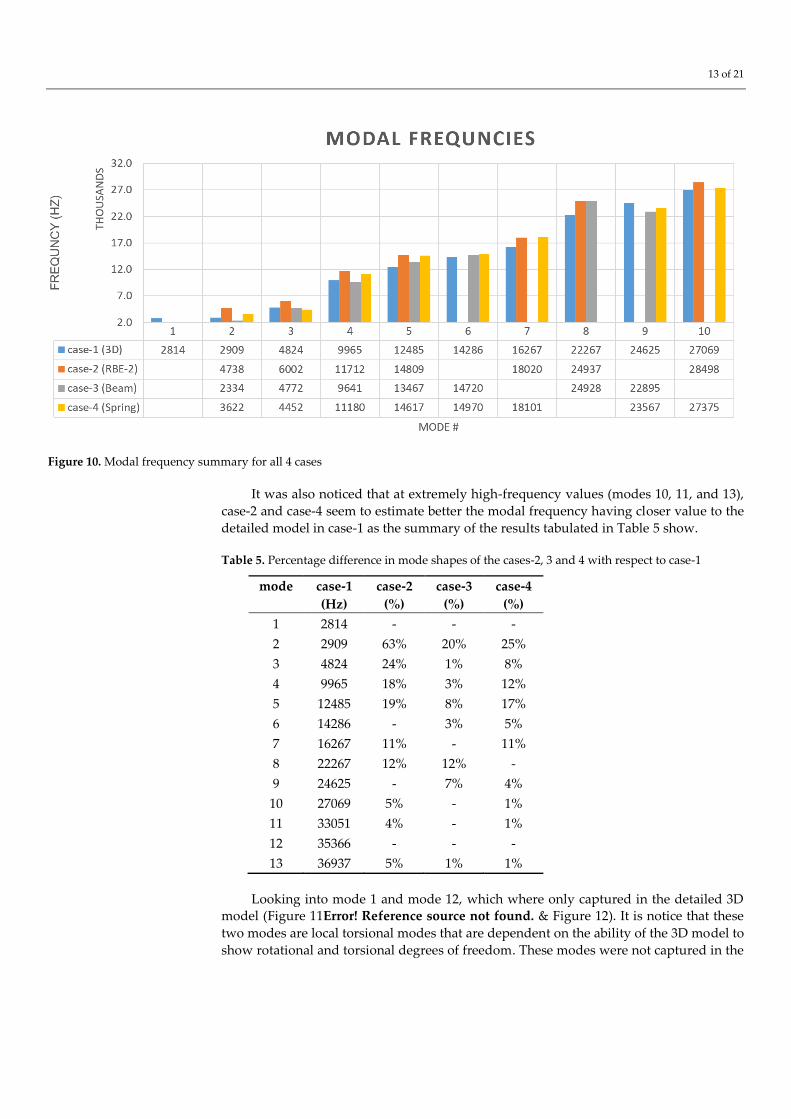
Figure 10. Modal frequency summary for all 4 cases
It was also noticed that at extremely high-frequency values (modes 10, 11, and 13),
case-2 and case-4 seem to estimate better the modal frequency having closer value to the
detailed model in case-1 as the summary of the results tabulated in Table 5 show.
Table 5. Percentage difference in mode shapes of the cases-2, 3 and 4 with respect to case-1
mode
case-1
(Hz)
case-2
(%)
case-3
(%)
case-4
(%)
1 2814 - - -
2 2909 63% 20% 25%
3 4824 24% 1% 8%
4 9965 18% 3% 12%
5 12485 19% 8% 17%
6 14286 - 3% 5%
7 16267 11% - 11%
8 22267 12% 12% -
9 24625 - 7% 4%
10 27069 5% - 1%
11 33051 4% - 1%
12 35366 - - -
13 36937 5% 1% 1%
Looking into mode 1 and mode 12, which where only captured in the detailed 3D model (Figure 11Error! Reference source not found. & Figure 12). It is notice that these
two modes are local torsional modes that are dependent on the ability of the 3D model to
show rotational and torsional degrees of freedom. These modes were not captured in the

14 of 21
any of the simplified 1-D bolt models due to such degrees of freedom being constrained.
Figure 11. Von Mises stresses in mode 1 (2814 Hz) from case-1
Figure 12. von Mises stresses in mode 12 (35366 Hz) from case-1
Even though the aspect ratio of the overall structure is not particularly high, the de-
tailed model in case-1 is more shows more capability in visualizing the complex motions
of the bolt. Where in the simplified models, 1-D bolts’ rigidity does not allow as much
motion. This increased rigidity in the 1-D elements is the main source is main source of
error in the modal frequencies shown in Table 3. Modes that are highly dependent on the
motion of the bolts have overestimated frequency values in the simplified models.
4.3 Effect of beam element discreitization
While not steering away from the main objective, the effect of discretizing the 1D
beam model of case-3 described in section 3.3.3 was analyzed. More specifically, four sub-
scenarios where investigated, where we discretize the bolt into 2 3, 4 and 10 elements
respectively. This was primarily done to try and capture some of the missing mode shapes
by offering the beam model more degrees of freedom. The results of the different finite
element simulations are summarized in Table 6 below.

15 of 21
Table 6. Effects of varying the number of beam element (case-3) on mode frequencies
The % difference shown is calculated with respect to the 1 element showing almost
no change in the different mode frequencies. Moreover, no extra mode shapes have been
made available by discretizing the bolt into multiple elements. This is because those are
torsional mode shapes, and the relevant theta degree of freedom will still be missing re-
gardless of the number of beam elements present in the model.
4.4 System strength evaluation (Static)
Stress values and reaction forces (lateral and axial) in each case/subcase were ex-
tracted from the analysis to calculate the margin of safety for the yield, ultimate, slipping
and gapping criteria based on Equations 1,2, 4 and 5 respectively. Figure 13 tabulates all
MoS calculations for the three simplified finite element models with respect to the full 3D
one of case-1. While stress contour plots on the simplified finite element models of cases
2, 3 and 4 are not all that informative, the Von Mises stress are shown here in Figure 13.
Modal frequencies for case-3 (beam) for different model discretization
mode
#
1 element 2 elements 3 elements 4 elements 10 elements
frequency
(Hz)
frequency
(Hz) %
frequency
(Hz) %
frequency
(Hz) %
frequency
(Hz) %
1 NA NA NA NA NA
2 2,334 2,335 0% 2,335 0% 2,335 0% 2,335 0%
3 4,772 4,775 0% 4,776 0% 4,776 0% 4,776 0%
4 9,641 9,646 0% 9,647 0% 9,647 0% 9,647 0%
5 13,467 13,033 1% 13,045 1% 13,049 1% 13,054 1%
6 14,720 14,719 0% 14,719 0% 14,719 0% 14,718 0%
7 NA NA NA NA NA
8 22,895 22,898 0% 22,898 0% 22,898 0% 22,898 0%
9 23,952 23,952 0% 23,952 0% 23,952 0% 23,952 0%
10 NA NA NA NA NA

16 of 21
Figure 13. Contour plots of the Von Mises stresses on the three loading scenarios on case-1
Figure 14. Bolts’ yield, ultimate, gapping, and slipping MoS values for all 4 FEM cases
The results in Figure 14 are based on the most conservative MoS value found in each
case/subcase loading scenario. It can be seen that for the yield, ultimate, and gapping MoS,
the simplified models show a similar more and slightly more conservative value com-
pared to the detailed model in case-1. The only discrepancy found was in the case of
MoSslipping where case-3 and case-4 showed a higher MoS value.
4.5 Bolt size effect
To further expand and validate the results of the different FE simplification modeled
used, two more bolts (different sizes and subsequently bolt preloads and tightening tor-
ques) were analyzed. The three bolts are the M3, M4 and M5 standardized bolts are sum-
marized in Table 7.
Table 7. Bolt size variations specs [37]
Bolt Data M3 M4 M5
Nominal Diameter (mm) 3 4 5
Thread pitch, 𝑝 (mm) 0.5 0.7 0.8
Nominal friction coefficient, 𝜇𝑡ℎ𝑟𝑒𝑎𝑑𝑠 0.3 0.3 0.3
Bolt friction uncertainty 0.1 0.1 0.1
tightening torque (Nm) 1.1 2.6 5.1
Joint preload (N) 1,135 2,009 3,164
A similar analysis to that presented in section 1.7 was performed on the three bolts
with the emphasis placed on the yield criteria, MOSyield. The percentage error for each
simplified finite element case for all 3 boll sizes were compared against their respective
converged full 3D finite element model. The loading in all bolt simulations was a 50 N

17 of 21
axial load with the same joint configuration and load application location as shown in
Figure 7. Only differences are the bolt nominal diameter, thread pitch and the joint pre-
load used for each as per the standard [37]. Also, worth noting that the tabulated % error
is calculated with respect to the near exact 3D results upon performing a convergence
analysis for each of the 3 bolts.
Table 8. Bolt specifications [37]
M3 M4 M5
MOSyield % error MOSyield % error MOSyield % error
Case-1
(3D bolt) 2.04 2.05 2.05
Case-2
(1D RBE2) 2.04 0 2.05 0 2.11 2.92
Case-3
(1D Beam) 2.03 0.49 2.03 0.97 2.1 2.43
Case-4
(1D spring) 2.03 0.49 2.03 0.97 2.1 2.439
The error is observed to increase with increasing bolt size, while still within accepta-
ble range. For larger assemblies with multiple bolts (granted their stress fields do not in-
teract), it is worth reducing the bolt to a 1D beam model as the computational cost would
be higher. In such cases, it is recommended that the factor of safety used in calculating the
MOSyield of Equation (4) to be increased to such that the overall output is more conserva-
tive. This is in line with what is expected since the larger the bolt size, the lesser of a beam-
like behavior it will have, with shear and through-thickness stresses becoming more prev-
alent.
4.6 Computational time
For this study, all simulation solvers were set to achieve an iterative solver conver-
gence value less than 𝟏 × 𝟏𝟎−𝟔. The device used for running the simulations has an Intel
Xeon 4-cors processor 32-GB RAM and 64-bit operating system. Taking that into consid-
eration, Table 9 shows the number of nodes and elements in each case and the correspond-
ing analysis computational time. Note that the discretization of case-3 into multiple beam
elements detailed section 4.3 did not yield to any tangible increase in the computational
time, and are this omitted from Table 9.
Table 9. Computational cost comparison
Case ID # of
Nodes
# of
Elements
Modal
analysis
Static
analysis
Case-1
(3D bolt) 114,340 81,201 2min 1sec 1min 45sec
Case-2
(RBE2) 378 326 1 sec 1 sec
Case-3
(1D Beam) 378 326 1 sec 1 sec
Case-4
(1D Spring) 378 326 1 sec 1 sec

18 of 21
5. Conclusion
In summary, the finite element simplification of a standard bolted joint configuration
is investigated using Siemens NX software. Static and modal analysis were used to get
insight on the accuracy of the simplification by comparing the computational results
against a near exact solution of the full 3D finite element model. Both static and modal
analysis were performed, and margin of safety values were computed for bolt slipping
and bolt gapping phenomena. It can be concluded that simplifying the finite element mod-
eling of bolted joints will yield comparable results while significantly cutting down on
computational cost. This is especially the case for smaller bolts (e.g. M3 and M4) where
the yield margin of safety was off by less than 1% in comparison with the 3D model.
Therefore, it is recommended to maintain a bolt slenderness ratio that is greater than 1.5.
While the three simplified models presented here fall short on capturing torsional mode
shapes and frequencies, the more common modes and stress results related to the overall
behavior of the joint are well captured. It was also determined that further discretizing
the 1D model beyond one beam element did not yield any significant improvement in the
modal frequencies determined. Moreover, and looking into the four margin of safety cri-
teria used in this manuscript, the three simplified finite element models proved to be more
conservative while offering significant savings computational time. This is critical in mod-
els with numerous bolted connections, where such finite element simplification will yield
a significant reduction in computational costs without sacrificing accuracy.
Author Contributions:
Conceptualization, A.M. Ibrahim and W.A. Samad.
Methodology, A.M. Ibrahim.
Software, A.M. Ibrahim.
Validation, A.M. Ibrahim and W.A. Samad.
Investigation, A.M. Ibrahim and W.A. Samad
Writing—original draft preparation, A.M. Ibrahim.
Writing—review and editing, A.M. Ibrahim and W.A Samad.
Supervision, W.A. Samad.
All authors have read and agreed to the published version of the manuscript.
Funding: This research received no external funding
Informed Consent Statement: Not applicable
Acknowledgments: The authors wish to thank the United Arab Emirates’ Ministry of Education for
their grant that allowed for the acquisition and use of Siemens NX software.
Conflicts of Interest: The authors declare no conflict of interest.
References
[1] A. Khaja, A. Kaliyanda, W. A. Samad and R. E. Rowlands, "Thermoelastic stress analysis of a mechanical fastener,"
in Imaging Methods for Novel Materials and Challenging Applications, Volume 3. Conference Proceedings of the Society for
Experimental Mechanics Series, New York, 2013.
https://doi.org/10.1007/978-1-4614-4235-6_14
[2] J. Reid and N. Hiser, "Detailed modeling of bolted joints with slippage," Finite Elements in Analysis and Design, vol.
41, no. 6, pp. 547-562, 2005.

19 of 21
https://doi.org/10.1016/j.finel.2004.10.001
[3] F. Esmaeili, M. Zehsaz and T. Chakherlou, "Investigation the effect of tightening torque on the fatigue strength of
double lap simple bolted and hybrid (bolted–bonded) joints using volumetric method," Materials & Design, vol.
63, pp. 349-359, 2014.
https://dx.doi.org/10.1016/j.matdes.2014.06.021
[4] F. Sen, M. Pakdil, O. Sayman and S. Benli, "Experimental failure analysis of mechanically fastened joints with
clearance in composite laminates under preload," Materials & Design, vol. 29, no. 6, pp. 1159-1169, 2008.
https://doi.org/10.1016/j.matdes.2007.05.009
[5] G. Valtinat, I. Hadrych and H. Huhn, "Strengthening of riveted and bolted steel constructions under fatigue
loading by preloaded fasteners-experimental and theoretical investigations," in Connections in Steel Structures IV,
2000.
[6] F. Esmaeili, T. N. Chakherlou, M. Zahsaz and S. Hasanifard, "Investigating the effect of clamping force on the
fatigue life of bolted plates using volumetric approach," Journal of Mechanical Science and Technology, vol. 27, pp.
3657-3664, 2013.
https://doi.org/10.1007/s12206-013-0911-3
[7] W. A. Samad, A. A. Khaja, A. R. Kaliyanda and R. E. Rowlands, "Hybrid Thermoelastic Stress Analysis of a Pinned
Joint," Experimental Mechanics, vol. 24, pp. 515-525, 2014.
https://doi.org/10.1007/s11340-013-9822-6
[8] A. I. o. S. C. (AISC), " Manual of steel construction, load and resistance factor," 1986.
[9] M. A. McCarthy, V. P. Lawlor and W. F. Stanley, "An Experimental Study of Bolt-Hole Clearance Effects in Single-
lap, Multibolt Composite Joints," Journal of Composite Materials, vol. 39, no. 9, pp. 799-825, 2005.
https://doi.org/10.1177/0021998305048157
[10] M. M. Frocht and H. N. Hill, "Stress concentration factors around a central circular hole in a plate loaded through
a pin in the hole," Applied Mechanics, vol. 7, pp. 5-9, 1940.
[11] A. A. Khaja and W. A. Samad, "Hybrid Digital Image Correlation," Journal of Engineering Mechanics, vol. 146, no.
4, 2020.
[12] W. Wunderlich and W. Pilkey, "Mechanics of Structures. Variational and Computational Methods," Meccanica, vol.
39, pp. 291-292, 2004.
[13] R. Grzejda, "Modelling bolted joints using a simplified bolt model," Journal if Mechanical and Trasport engineering,
2017.
DOI 10.21008/j.2449-920X.2017.69.1.03
[14] E. Paroissien, F. Lachaud, S. Schwartz, A. Da Veiga and P. Barriere, "Simplified stress analysis of hybrid
(bolted/bonded) joints," International Journal of Adhesion and Adhesives, vol. 77, pp. 183-197, 2017.
10.1016/j.ijadhadh.2017.05.003
[15] K. J. Belisle, "Experimental and Finite Element Analysis of a Simplified Aircraft Wheel Bolted Joint Model," The
Ohio State University, Ohio, 2009.

20 of 21
[16] J. G. Williams, R. E. Anley, D. H. Nash and T. G. Gray, "Analysis of externally loaded bolted joints: Analytical,
computational and experimental study," International Journal of Pressure Vessels and Piping, vol. 86, no. 7, pp. 420-
427, 2009.
https://doi.org/10.1016/j.ijpvp.2009.01.006
[17] J. Montgomery, "Methods for Modeling Bolts in the Bolted Joint," in ANSYS User's Conference Vol 5, Orlando, FL,
2002.
[18] J. Kim, J.-C. Yoon and B.-S. Kang, "Finite element analysis and modeling of structure with bolted joints," Applied
Mathematical Modelling, vol. 31, no. 5, pp. 895-911, 2007.
https://doi.org/10.1016/j.apm.2006.03.020
[19] B. Reuss, Computer Aided Technology, LLC, 2018. [Online]. Available: https://www.cati.com/blog/2018/11/why-
you-should-simplify-your-analysis/
[20] W. A. Samad and K. Suresh, “CAD-integrated analysis of 3-D beams: a surface-integration approach,” Engineering
with Computers, vol. 27, no. 3, pp. 201-210, 2011.
[21] L. Paracchini, C. Barbieri, M. Redaelli, D. Di Croce, C. Vincenzi, and R. Guarnieri, “Finite Element Analysis of a
New Dental Implant Design Optimized for the Desirable Stress Distribution in the Surrounding Bone Region,”
Prosthesis, vol. 2 , no. 3, pp. 225-236, 2020.
[22] M. Cicciù, G. Cervino, D. Milone, and G. Risitano, “FEM Investigation of the Stress Distribution over Mandibular
Bone Due to Screwed Overdenture Positioned on Dental Implants,” Materials, vol. 11 , no. 9, pp. 1512, 2018.
[23] H. Relf, C. Barberio, and D. Espino, “A Finite Element Model for Trigger Finger,” Prosthesis, vol. 2, pp. 168-184,
2020.
[24] J. S. Tsai and Y. F. Chou, "The identification of dynamic characteristics of a single bolt joint," Journal of Sound and
Vibration, vol. 125, no. 3, pp. 487-502, 1988.
https://doi.org/10.1016/0022-460X(88)90256-8
[25] A. Javanmardi, R. Abadi, A. Marsono, M. T. Masine, I. Zulkepli and A. Ahmad, "Correlation of Stiffness and
Natural Frequency of Precast Frame System," Applied Mechanics and Materials, vol. 735, pp. 141-144, 2015.
https://doi.org/10.4028/www.scientific.net/AMM.735.141
[26] "Slippage in bolted connections," EnterFEA, 2016.
[27] Andy, "Bolts, Preload Explained," 29 December 2017. [Online]. Available:
https://medium.com/@bananajutsu/bolted-joint-preload-9ead1f81511b.
[28] R. Wingate, An overview of Fastener Requirements in the new NASA-STD-5020, NESC Academy NASA, 2013.
[29] D. Derry, "Rules of Thumb for Thread Engagement," Field Fastener, 13 March 2018. [Online]. Available:
https://fieldfastener.com/2018/03/13/rules-of-thumb-for-thread-engagement/.
[30] Genfast, "Minimum Thread Engagement (Bolt Failure) Chart - Metric," General Fastener Comany, Madison
Heights, MI.
[31] S. Ghosh, "Screw or Bolt Thread Engagement Length Calculation," MechGuru , 7 December 2012. [Online].
Available: https://mechguru.com/machine-design/screw-or-bolt-thread-engagement-length-calculation/.
[32] J. D. Reid and N. R. Hiser, "Detailed modeling of bolted joints with slippage," Finite Elements in Analysis and Design,
vol. 41, no. 6, pp. 547-562, 2005.
[33] E. C. f. S. Standardization, "Threaded fasteners handbook," Noordwijk, 2010.

21 of 21
[34] K. H. Brown, C. Morrow, S. Durbin and A. Baca, "Guideline for Bolted Joint Design and Analysis: Version 1.0,"
Sandia National Laboratories, Albuquerque, 2008.
[35] P. Esnault and M. Klein, "Factors of safety and reliability—present guidelines & future
ts," Proceedings of the conference on spacecraft structures, materials & mechanical testing, SP-386, Nordwijk, The
Netherlands, March 27–29, European Space Agency, pp. 109–119, 1996
[36] K. Bernstein, R. Kujala, V. Fogt and P. Romine, "Structural Design Requirements and Factors of Safety for
Spaceflight Hardware: For Human Spaceflight," National Aeronautics and Space Administration Lyndon B.
Johnson Space Center, Houston , 2011
[37] Bossard, "Hex socket head cap screws," Bossard, [Online]. Available:
https://eu.shop.bossard.com/group/en/8500/socket-products/hex-socket-head-cap-screws/bn-7_hex-socket-head-
cap-screws-fully-threaded.