on the eigenfilter design method and its applications: a ... · pdf fileieee transactions on...
TRANSCRIPT

IEEE TRANSACTIONS ON CIRCUITS AND SYSTEMS—II: ANALOG AND DIGITAL SIGNAL PROCESSING, VOL. 50, NO. 9, SEPTEMBER 2003 497
On The Eigenfilter Design Method and ItsApplications: A Tutorial
Andre Tkacenko, Student Member, IEEE, P. P. Vaidyanathan, Fellow, IEEE, andTruong Q. Nguyen, Senior Member, IEEE
Abstract—The eigenfilter method for digital filter designinvolves the computation of filter coefficients as the eigenvector ofan appropriate Hermitian matrix. Because of its low complexity ascompared to other methods as well as its ability to incorporate var-ious time and frequency-domain constraints easily, the eigenfiltermethod has been found to be very useful. In this paper, we presenta review of the eigenfilter design method for a wide variety offilters, including linear-phase finite impulse response (FIR) filters,nonlinear-phase FIR filters, all-pass infinite impulse response(IIR) filters, arbitrary response IIR filters, and multidimensionalfilters. Also, we focus on applications of the eigenfilter methodin multistage filter design, spectral/spacial beamforming, and inthe design of channel-shortening equalizers for communicationsapplications.
Index Terms—Channel-shortening equalizers, constrained filterdesign, eigenfilter, least-squares filter design.
I. INTRODUCTION
T HE EIGENFILTER design method for discrete time fil-ters involves the determination of filter coefficients as
the eigenvector of a particular Hermitian positive definite (andoften real and symmetric) matrix. As opposed to other filter de-sign algorithms such as the least-squares approach [48], whichrequires the computation of a matrix inverse, the eigenfiltermethod only requires the computation of a single eigenvector,which can be found efficiently via the iterative power method[49]. In addition to its inherently low design complexity, theeigenfilter method can also incorporate a variety of time andfrequency-domain constraints into the design problem with rel-ative ease, in contrast to other well known filter design methodssuch as the McClellan–Parks algorithm [16]. Furthermore, be-cause of the myriad of design problems that can be posedas an eigenfilter problem, the method has been shown to beuseful for a variety of applications, ranging from spectral/spa-cial filtering or beamforming to communications regarding thedesign of channel-shortening equalizers for discrete multitone(DMT) systems.
The notion of such a filter design technique was introducedby Slepian in 1978 [42] in the context of the design of windowfunctions for the ideal low-pass filter response. Slepian consid-ered the problem of designing a window with a minimum stop-
Manuscript received February 5, 2003; revised April 23, 2003. This work wassupported in part by the Office of Naval Research Grant N00014–99-1–1002.
A. Tkacenko and P. P. Vaidyanathan are with the Department of ElectricalEngineering, California Institute of Technology, Pasadena, CA 91125 USA(e-mail: [email protected]).
T. Q. Nguyen is with the Department of Electrical and Computer Engineering,University of California at San Diego, La Jolla, CA 92093 USA.
Digital Object Identifier 10.1109/TCSII.2003.816942
band energy (subject to a unit norm constraint on the windowcoefficients to avoid a trivial solution). It was found that the op-timal window coefficients could be found from the eigenvectorof a real, symmetric, positive definite, Toeplitz matrix corre-sponding to its smallest eigenvalue.
In 1987, Vaidyanathan and Nguyen [50] generalizedSlepian’s method for window design to the design oflinear-phase finite impulse response (FIR) filters and formallyintroduced the eigenfilter design method. They generalizedSlepian’s method to account for both passband and stopbandconditions and showed how to design a variety of filters (mainlylow pass, high pass, and band pass) with various time- andfrequency-domain constraints, including the Nyquist constraintand flatness constraints [49]. Numerous simulation results wereprovided showing the power and usefulness of the eigenfiltermethod.
Since then, various generalizations of the eigenfilter methodhave been proposed. The design of linear-phase FIR Hilberttransformers and arbitrary order digital differentiators was con-sidered by Pei and Shyu in [24], [25], [28], [36]. More generalFIR design methods were considered by Nguyen as well as Peiand Shyu, including the design of linear-phase filters with arbi-trary amplitude response [20], the design of arbitrary complexcoefficient nonlinear-phase filters [27], [29], [21], and the de-sign of th band nonlinear-phase filters by Wisutmethangoonand Nguyen [52]. Multidimensional extensions to the eigenfiltermethod (mostly two dimensional) were originally proposed byNashashibi and Charalambous [18] and later considered by Peiand others [26], [30], [31], [35], [8]. The eigenfilter method haseven been used to design infinite impulse response (IIR) filters,including all-pass filters [14], [41], [33], [22], [55], arbitraryIIR filters using a time-domain [32] and a frequency-domainapproach [1], [2], and IIR filters with time and frequency-do-main constraints [39]. Recently, eigenfilter methods for filterswith general linear constraints were proposed [37] along withmethods based on a total least-squares-error criterion [38], [54].
As many design problems can be posed as an eigenfilterproblem, the eigenfilter method has been found to be useful forseveral applications. For example, it has been used to designmultistage interpolated FIR (IFIR) filters [9] as well as arbitrarylog magnitude and phase response filters [34]. In addition, it hasbeen used to develop prototype filters for pseudo-quadraturemirror filter (pseudo-QMF) uniform and nonuniform cosinemodulated filter banks [3], [4]. The generalization of the eigen-filter approach to solve general least-squares approximationproblems was proposed in [10]. Applications to spectral/spatialfiltering were also shown in [10] and more recently in [11].
1057-7130/03$17.00 © 2003 IEEE

498 IEEE TRANSACTIONS ON CIRCUITS AND SYSTEMS—II: ANALOG AND DIGITAL SIGNAL PROCESSING, VOL. 50, NO. 9, SEPTEMBER 2003
In addition, the eigenfilter method has been found useful forcancelling selective signals in an acoustic environment [6],[7]. Use of this method for image scaling or size conversionwas shown in [53]. Recently, the eigenfilter method has beenshown to be very important in communications, especially forthe design of channel-shortening equalizers in DMT systems[43]. Melsa et al. [17] were the first to apply the eigenfiltermethod to the problem of channel shortening. Since then, manyother eigenfilter based channel-shortening equalizers havebeen proposed [40], [45]–[47], [5]. Several of these methodshave been found to perform nearly optimally in terms of theobserved bit rate.
A. Outline
This paper is organized as follows. In Section II, we give abrief review of the early work on eigenfilters and focus mainlyon the work of Slepian [42] and Vaidyanathan and Nguyen [50].Various generalizations of the eigenfilter approach for filter de-sign are discussed in Section III. In Section IV, applications ofthe eigenfilter method are considered, such as multistage filterdesign, spectral/spacial beamforming, and channel shorteningfor communications. Finally, concluding remarks are made inSection V.
B. Notations
All notations are as in [49] unless mentioned otherwise.In particular, ( ), ( ), and ( ) correspond, respectively, tothe conjugate, transpose, and conjugate transpose operations.Vectors and matrices are in bold font with lowercase letterscorresponding to vectors and uppercase letters to matrices. The
th element of a vector will be denoted by , whereas theth element of a matrix will be denoted by .
II. HISTORICAL BACKGROUND
A. Prolate Spheroidal Wave Sequences
A classical approach for designing FIR low-pass filters is thewindowing method [49], in which the impulse response of anideal low-pass filter is multiplied by a window function .Typically, the window is also low-pass and it turns out that twoparameters of the frequency response of the windowmost prominently affect the quality of the overall response [49].As the main lobe width of increases, the transition band-width of the windowed response likewise tends to get larger,while as the peak sidelobe level of increases, the peakpassband and stopband ripples of the overall response also tendto as well. To mitigate the sidelobe level effects of , in[42], Slepian considered designing a real window of unit normfor which the energy in the frequency region isminimized, for some with . Such a window isa discrete timeprolate spheroidal wave function, also called aprolate spheroidal wave sequence[49]. Slepian showed that thecoefficients of a prolate spheroidal wave sequence could be ob-tained from the eigenvector corresponding to the smallest eigen-value of a real, symmetric, positive definite, Toeplitz matrix, aswe now show.
Suppose that is a real causal sequence of lengthfor some nonnegative integer. Then, the transform of ,
namely , is a real coefficient polynomial in of ordergiven by . The prolate spheroidal wavesequence is the one that minimizes
(1)
subject to the unit norm constraint
(2)
If we define the following column vectors:
then and (asis real). Using this in (1) yields
where (3)
As is clearly Hermitian, we can decomposeas, where and are, respectively, real symmetric and anti-
symmetric matrices [12]. Then, asis real, we have, and so from (3) we get
(4)
The th element of is given by
(5)
Clearly, is a Toeplitz matrix (as depends only on), in addition to being real, symmetric, and positive definite
(as ) [12]. The unit norm constraint of (2) is equivalentto the statement
(6)
Combining (4) and (6), the optimization problem can be posedas follows:
Minimize subject to
As is Hermitian, it follows byRayleigh’s principle[12]that the minimum value of is where is the smallesteigenvalue of . Furthermore, this minimum value is achievedif , where denotes a unit norm eigenvector ofcorresponding to . (More generally, iff is any unitnorm vector in the eigenspace corresponding to. However,for sake of clarity, we will ignore this scenario.)
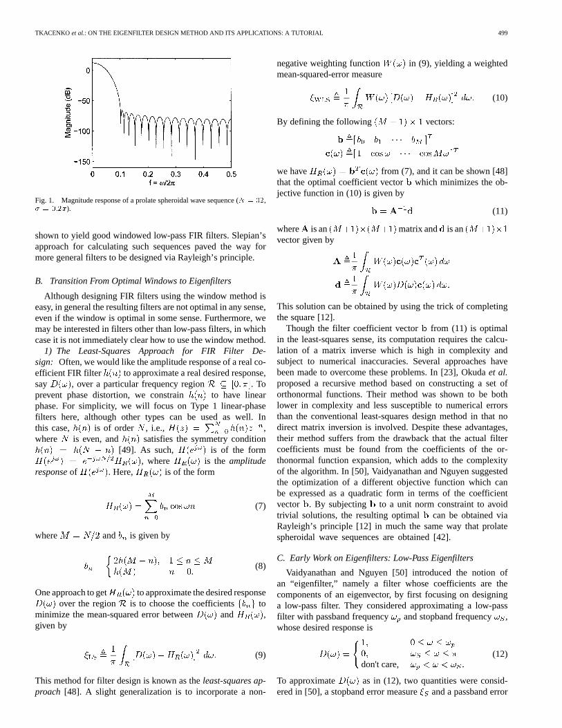
The magnitude response of a prolate spheroidal wave se-quence obtained using Rayleigh’s principle is shown in Fig. 1.Here, we chose the order to be and the frequencyparameter as . As can be seen from Fig. 1, the windowexhibits a large attenuation near or andmost of the energy is concentrated in the regionas expected. Windows designed using the above method were
TKACENKO et al.: ON THE EIGENFILTER DESIGN METHOD AND ITS APPLICATIONS: A TUTORIAL 499
Fig. 1. Magnitude response of a prolate spheroidal wave sequence (N = 32,� = 0:2�).
shown to yield good windowed low-pass FIR filters. Slepian’sapproach for calculating such sequences paved the way formore general filters to be designed via Rayleigh’s principle.
B. Transition From Optimal Windows to Eigenfilters
Although designing FIR filters using the window method iseasy, in general the resulting filters are not optimal in any sense,even if the window is optimal in some sense. Furthermore, wemay be interested in filters other than low-pass filters, in whichcase it is not immediately clear how to use the window method.
1) The Least-Squares Approach for FIR Filter De-sign: Often, we would like the amplitude response of a real co-efficient FIR filter to approximate a real desired response,say , over a particular frequency region . Toprevent phase distortion, we constrain to have linearphase. For simplicity, we will focus on Type 1 linear-phasefilters here, although other types can be used as well. Inthis case, is of order , i.e., ,where is even, and satisfies the symmetry condition
[49]. As such, is of the form, where is the amplitude
responseof . Here, is of the form
(7)
where and is given by
.(8)
One approach to get to approximate the desired responseover the region is to choose the coefficients to
minimize the mean-squared error between and ,given by
(9)
This method for filter design is known as theleast-squares ap-proach [48]. A slight generalization is to incorporate a non-
negative weighting function in (9), yielding a weightedmean-squared-error measure
(10)
By defining the following vectors:
we have from (7), and it can be shown [48]that the optimal coefficient vector which minimizes the ob-jective function in (10) is given by
(11)
where is an matrix and is anvector given by
This solution can be obtained by using the trick of completingthe square [12].
Though the filter coefficient vector from (11) is optimalin the least-squares sense, its computation requires the calcu-lation of a matrix inverse which is high in complexity andsubject to numerical inaccuracies. Several approaches havebeen made to overcome these problems. In [23], Okudaet al.proposed a recursive method based on constructing a set oforthonormal functions. Their method was shown to be bothlower in complexity and less susceptible to numerical errorsthan the conventional least-squares design method in that nodirect matrix inversion is involved. Despite these advantages,their method suffers from the drawback that the actual filtercoefficients must be found from the coefficients of the or-thonormal function expansion, which adds to the complexityof the algorithm. In [50], Vaidyanathan and Nguyen suggestedthe optimization of a different objective function which canbe expressed as a quadratic form in terms of the coefficientvector . By subjecting to a unit norm constraint to avoidtrivial solutions, the resulting optimal can be obtained viaRayleigh’s principle [12] in much the same way that prolatespheroidal wave sequences are obtained [42].
C. Early Work on Eigenfilters: Low-Pass Eigenfilters
Vaidyanathan and Nguyen [50] introduced the notion ofan “eigenfilter,” namely a filter whose coefficients are thecomponents of an eigenvector, by first focusing on designinga low-pass filter. They considered approximating a low-passfilter with passband frequency and stopband frequency ,whose desired response is
don't care,(12)
To approximate as in (12), two quantities were consid-ered in [50], a stopband error measureand a passband error

500 IEEE TRANSACTIONS ON CIRCUITS AND SYSTEMS—II: ANALOG AND DIGITAL SIGNAL PROCESSING, VOL. 50, NO. 9, SEPTEMBER 2003
measure . For the stopband error , the mean-squared errorof (9) was used, given by
(13)
where is a real, symmetric, positive definte matrix given by
Unlike the stopband error measure, if the mean-squared error of(9) for the passband error is used, the resulting expression willnot be in the form of a quadratic form in terms of the vector. Tobypass this dilemma, a reference frequency was introduced intothe design problem and the passband error measure was takento be the deviation of the amplitude response from its value atthe reference frequency. In particular, for, the deviation of
from its value at the reference frequency wasmeasured. As , where is an vectorof all 1’s, was chosen to be
(14)
where is a real, symmetric, positive definite matrix given by
To jointly minimize both and , the authors in [50] con-sidered minimizing a convex combination [12] of the two. Inparticular, the vector was chosen to minimize
(15)
where is a tradeoff parameter between stopband and passbandperformances. In light of (13) and (14),in (15) can be ex-pressed as follows:
where (16)
Note that the matrix is itself a real, symmetric, positive def-inite matrix since . If we impose that has unitnorm, i.e., , to avoid trivial solutions, then the optimal
which minimizes in (16) is simply the eigenvector corre-sponding to the minimum eigenvalue of by Rayleigh’sprinciple [12].
As opposed to the least-squares approach for filter designwhich requires the computation of a matrix inverse as can beseen from (11), the eigenfilter method only requires the com-putation of a single eigenvector of a Hermitian positive definitematrix. This eigenvector can be calculated efficiently using theiterative power method [12], [49]. The power method, which isformally used to calculate the largest eigenvalue of a Hermitianpositive semidefinite matrix and its corresponding eigenvector,is known to converge quickly when the largest eigenvalue ismuch larger in magnitude than the next largest eigenvalue. In
Fig. 2. Magnitude responses obtained using the least-squares approach alongwith the eigenfilter approach. (! = 0:3�,! = 0:35�,N = 24,W (!) = 1,� = 1=2).
such cases, the complexity of the eigenfilter method is muchless than that of the least-squares approach.
In Fig. 2, the magnitude responses using the eigenfiltermethod as well as the least-squares approach are plotted fora low-pass filter with and . Here, thefilter order was chosen to be and equal weighingwas used for both the passband and stopband (i.e., we chose
for the least-squares approach and for theeigenfilter method). The eigenfilter was rescaled to have unitygain at . From the plots, it can be seen that the eigenfilteris very similar to the least-squares filter, although the formerperforms slightly worse in some parts of the stopband. Asincreases, the two responses become more and more alike.The close agreement between the least-squares approach andthe eigenfilter method, along with the lower complexity of thelatter, show the merits of the eigenfilter method.
As mentioned earlier, the tradeoff parametercontrols theperformances of the passband and stopband. When , mostof the design emphasis is on the stopband, and consequently thestopband ripple sizes are smaller than for other values of. Asimilar scenario holds for the passband when .
In addition to designing low-pass filters using the eigenfilterapproach, the authors in [50] also showed how to design band-pass and multiband filters with the introduction of different ref-erence frequencies.
1) Incorporating Time- and Frequency-Domain Con-straints: Another advantage of the eigenfilter method shownby Vaidyanathan and Nguyen is the ease with which certaintime and frequency-domain constraints can be accounted forin the design. In particular, they focused on the time-domainNyquist constraint [49] and also a frequency-domain flatnessconstraint. It was shown that even with such constraints, theresulting filter coefficients could be found using the eigenfiltertechnique.
In [50], the authors first considered the Nyquist constraint.The causal FIR filter of order we have focused onthus far is said to satisfy the Nyquist constraint [or said to beNyquist ( )] if [49], [50]
(17)
where is some positive integer and is some constant. Inother words, the advanced response be-
TKACENKO et al.: ON THE EIGENFILTER DESIGN METHOD AND ITS APPLICATIONS: A TUTORIAL 501
comes an impulse after being decimated by[49]. Using (8),the coefficients must satisfy
As such, the coefficient vector is of the form in (18), shownat the bottom of the page. From (16) and (18), it is apparent thatthe rows and columns of whose indices are nonzero multiplesof do not contribute to the overall error . Hence,
can be rewritten as
where is simply the vector of (18) with the zeros removed,as shown in the second equation at the bottom of the page and
is the matrix obtained by removing the rows and columns ofwhose indices are nonzero multiples of. From (18), the
constraint is equivalent to . Thus, the designproblem is to minimize subject to , whichis the traditional eigenfilter problem, but with the smaller matrix
.In addition to showing how the Nyquist constraint could be
incorporated in the design of eigenfilters, it was also shown howto incorporate flatness constraints in the frequency domain. Bydefinition [49], a frequency response is said to have adegree of flatness of at the frequency if we have
(19)
For simplicity, the authors in [50] focused on a flatnessconstraint at and later showed how to accomodate forany arbitrary frequency . Recall that from (7) isan expansion in terms of the functions . Alter-natively, can be expressed in terms of the functions
, yielding the expansion
(20)
With this expansion, it can easily be shown that the flatnessconstraints of (19) are satisfied for ,
, and iff for . Thus, iffor , then has a degree of flatnessat . Assuming this to be the case, then by defining thefollowing vectors:
(21)
we have . Note that the vector is completelyarbitrary and that the flatness constraint is automatically satis-fied by construction. In this case, the objective function from
(15) takes on the form , where is as in (16) butwith and , given by
where . Under the unit norm con-straint , can be minimized using Rayleigh’s principleas before. To generalize this approach to have a degreeof flatness at any arbitrary frequency, we need only expand
in terms of the functions .2) Iterative Eigenfilter Method for the Design of Equiripple
Filters: The McClellan–Parks algorithm [16], which mini-mizes the norm of the response error, is widely used forequiripple filter design on account of its rapid convergenceand good performance. However, incorporating time- andfrequency-domain constraints into the design, such as thosefrom above, is often very difficult. The relative ease with whichthe eigenfilter method can accomodate such constraints was theprimary motivation for Vaidyanathan and Nguyen to develop aniterative eigenfilter technique for designing equiripple filters.
To formulate an iterative technique, the authors in [50] intro-duced a weight function for the passband and stopbanderror measures of (14) and (13), respectively, given by
where and . For uni-form weighting (i.e., ), the errors andwere observed to be large near the band edges and smaller awayfrom them. As and are not knowna priori, an iter-ative procedure to identify the appropriate was suggestedbased on the above observation. If and denotethe passband and stopband error curves after theth iteration,the weighting function for the th iteration was chosen as
with the initialization . Here, either andor their envelopes can be used. The iteration is car-
ried out until the magnitude of the difference in the solutionsis smaller than a prescribed small constant. In other words, theiteration is carried out until .
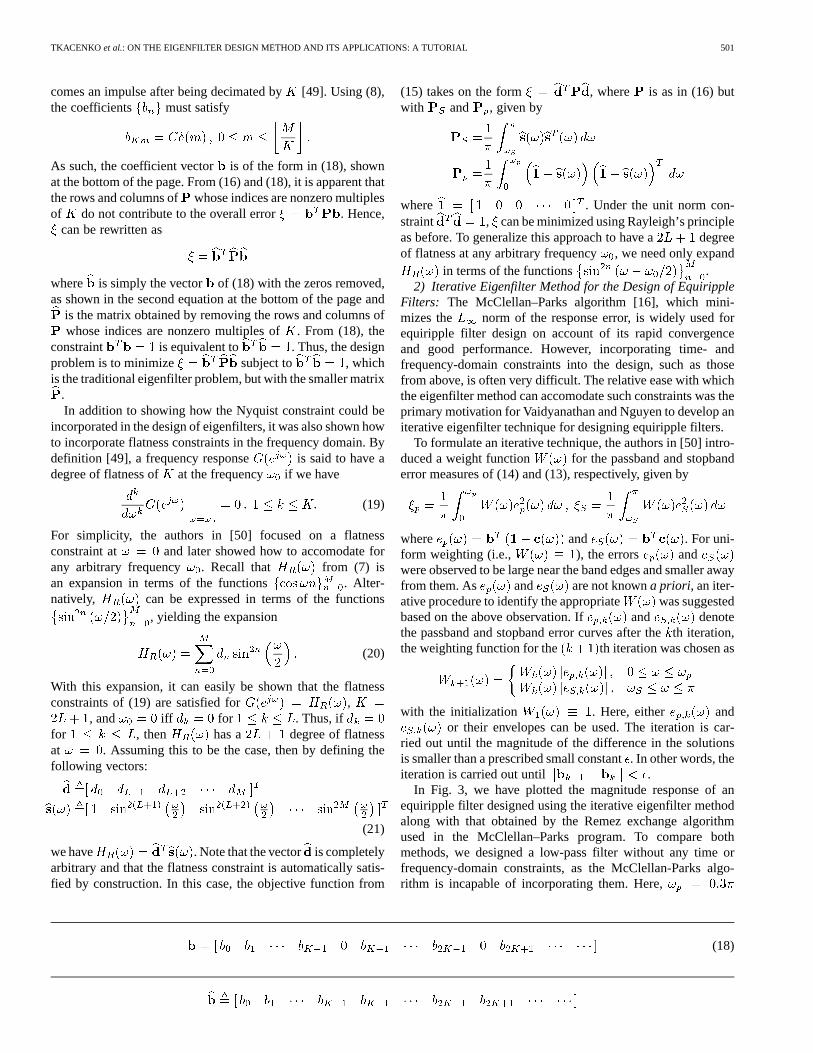
In Fig. 3, we have plotted the magnitude response of anequiripple filter designed using the iterative eigenfilter methodalong with that obtained by the Remez exchange algorithmused in the McClellan–Parks program. To compare bothmethods, we designed a low-pass filter without any time orfrequency-domain constraints, as the McClellan-Parks algo-rithm is incapable of incorporating them. Here,
(18)
502 IEEE TRANSACTIONS ON CIRCUITS AND SYSTEMS—II: ANALOG AND DIGITAL SIGNAL PROCESSING, VOL. 50, NO. 9, SEPTEMBER 2003
Fig. 3. Magnitude response of equiripple filters designed using the eigenfilterand Remez exchange algorithms. (a) Magnitude response plot on a decibel scale.(b) Passband details using a nondecibel scale.
and , and we chose for both methods.For the eigenfilter method, we chose . A decibel plotof the magnitude response is shown in Fig. 3(a), while thepassband details are shown in Fig. 3(b) on an nondecibel scale.From Fig. 3(a), we see that both methods are in excellentagreement. The eigenfilter is only approximately equiripplesince the reference frequency condition at preventsthis frequency from being an extremal frequency. As such, theeigenfilter exhibits a larger, albeit only slightly larger, errorthan the filter designed using the Remez exchange algorithm.Using the methods of the previous subsection, we can createapproximately equiripple eigenfilters that satisfy certain timeand frequency-domain constraints.
III. GENERALIZATIONS OF THEEIGENFILTER METHOD
Since the work of Vaidyanathan and Nguyen [50], many gen-eralizations have been made to the eigenfilter method. In thissection, we will focus on several such extensions, includingusing the eigenfilter method to design arbitrary amplitude andfrequency response filters and incorporating general linear con-straints into the design. In addition, we will review a recenteigenfilter method based on a total least-squares-error criterion.Then, we will show how the eigenfilter method can be used to
design IIR filters including all-pass filters. Finally, we will focuson designing multidimensional FIR filters using the eigenfiltermethod.
A. Arbitrary Desired Response Eigenfilters
Nguyen originally considered the problem of using the eigen-filter method to approximate an arbitrary real desired amplituderesponse using linear-phase FIR filters [20]. Later, themethod was generalized to approximating a general complex de-sired response with a complex coefficient FIR filter [21],[29]. Here, we present the methods of [20], as well as those of[29].
1) Arbitrary Amplitude Response Case:In order to approx-imate any real desired amplitude response with a linear-phase FIR filter using the eigenfilter method, Nguyen [20]considered modifying the least-squares-error criterion (9) byincorporatinga reference frequencyatwhich theFIR filterampli-tude response would exactly match . More specif-ically, Nguyen considered minimizing the objective function
(22)
(In [20], Nguyen considered the special case , buthere we include an arbitrary for sake of generality.) Here,
is the reference frequency which is chosen by the designer.Note that the error function is chosen by construction to bezero at . In [20], was chosen to be
(23)
where denotes the boundary of the region, whereas in[21], was chosen to be
(24)
Pei and Shyu [29] showed through a design example that thechoice of had a noticable effect on the overall performanceof the resulting filter. From their simulations, it could be seenheuristically that choosing where was large in magni-tude yielded better results, thus justifying the choices ofsug-gested by Nguyen in (23) and (24). Using the fact that
, it can be shown from (22) that we have the equa-tion shown at the bottom of the page. As before, the matrix
is a real, symmetric, positive definite matrix. With the usualunit norm constraint on , the optimal coefficientsfor can be obtained using the eigenfilter method as be-fore. It should be noted that after the optimalis found, thesolution must be scaled in order to satisfy the reference fre-quency condition that , which is equivalentto .
TKACENKO et al.: ON THE EIGENFILTER DESIGN METHOD AND ITS APPLICATIONS: A TUTORIAL 503
2) Arbitrary Desired Response Case:Nguyen as well as Peiand Shyu independently developed different methods to designa complex coefficient FIR filter to approximate a generally com-plex valued desired response using the eigenfilter method [29],[21]. Here, we present the method of Pei and Shyu [29].
Let be a causal FIR filter of length , so that. Defining the vectors
(25)
we clearly have . To develop an eigenfilter-based method for approximating a complex valued desired re-sponse , Pei and Shyu considered modifying the followingleast-squares objective function,
(26)
in order to express it as a quadratic form in terms of the vector.(In [29], the authors did not include the weight functionor the constant in their analysis. We have decided to in-clude both quantities for sake of completeness.) The frequencyregion is now a subset of the interval and the desiredresponse is allowed to be complex. Similarly to what wasdone in the previous section, to pose the design problem as aneigenfilter problem, Pei and Shyu modified (26) to incorporatea reference frequency at which the frequency response of thefilter would match the desired response. In particular, they con-sidered minimizing the objective
(27)
subject to the unit norm constraint . Using, it can be shown that we have the equation shown at
the bottom of the page. Here, the matrix is a com-plex-valued Hermitian, positive definite matrix. Under the unitnorm constraint , the optimal filter coefficients can befound using Rayleigh’s principle, which applies for any Her-mitian matrix, be it real or complex. After obtaining the optimalcoefficients, the resulting filter must be scaled in order to satisfythe reference frequency condition
. In [21], Nguyen solved the same problem, but decou-pled into real and imaginary parts and then expressed theobjective as a quadratic form in terms of the vector of real andimaginary parts of . Whereas Pei and Shyu’s method in-volved an complex matrix, Nguyen’s method involveda real matrix.
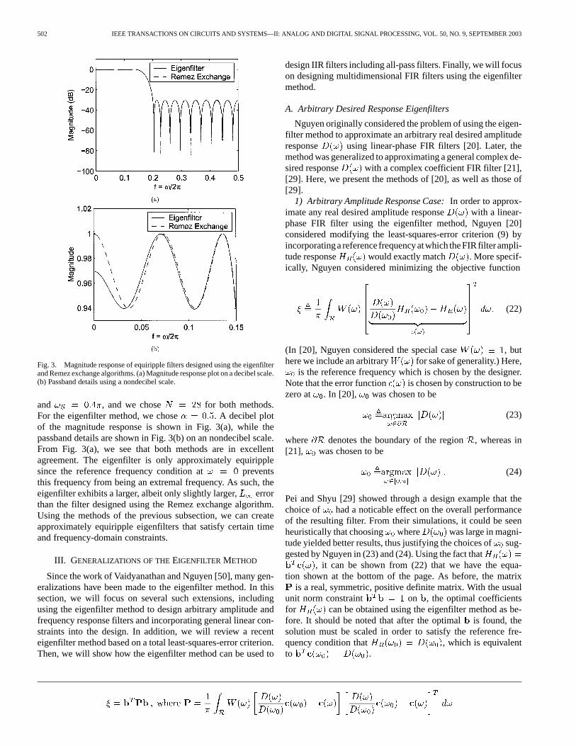
As an example, suppose that the magnitude and group delayof the desired response are as shown in Fig. 4(a) and (b),respectively. (This example was considered by Nguyen [21].)Recall that the group delay is the negative of the deriva-tive of the phase with respect to [49]. Namely, if
Fig. 4. (a) Desired magnitude response. (b) Desired group delay response.
, then . With a filter lengthof , a reference frequency of , and uni-form weighting, the resulting eigenfilter magnitude and groupdelay responses are shown in Fig. 5(a) and (b). As we can see,the eigenfilter designed here yielded a good fit to the desired re-sponse in the frequency regions of interest.
B. Incorporating General Linear Constraints Using theEigenfilter Approach
Often times in the design of FIR filters, it is desired thatthe filter coefficients satisfy a general linear constraint. For ex-ample, if we consider the complex coefficient FIR filter fromSection III-A-2, suppose that in addition to choosing toapproximate , we would like as well as its firstderivatives to match those of at some reference frequency
. Namely, we wish to choose to satisfy
(28)
Note that this is similar to the flatness constraints of (19) con-sidered in Section II-C-1. As we have
, the constraints in (28) can be rewritten in the form
(29)

504 IEEE TRANSACTIONS ON CIRCUITS AND SYSTEMS—II: ANALOG AND DIGITAL SIGNAL PROCESSING, VOL. 50, NO. 9, SEPTEMBER 2003
Fig. 5. (a) Magnitude response of the complex eigenfilter. (b) Group delayresponse. (N = 50, ! = 0:85�).
where is a matrix and is a columnvector given by
......
Note that the constraint equation in (29) is linear with respect tothe coefficient vector . Incorporating general linear constraintsas in (29) using the eigenfilter approach was first considered byChen [10] for the special case where and later generalizedby Peiet al. [37] for . We present the results of [37].
Recall that for the complex case, the eigenfilter problem istypically formulated as follows:
Minimize subject to
where is some Hermitian matrix. It should be noted that theconstraint here is really just included to prevent trivial solu-tions from occuring. Typically after the optimalis found, thetrue coefficient vector that we use is the optimal scaledby a factor in order to satisfy the reference frequency condi-tion. In other words, we use , where is chosensuch that we have (which implies
). By expressing as a Rayleigh quotient
[12] in terms of the true coefficient vector, the design problembecomes
Minimize
over all nonzero vectors. By Rayleigh’s principle, the min-imum value of is the smallest eigenvalue of which occursiff is in the eigenspace corresponding to. Note that here thelength of is arbitrary. In the eigenfilter design problem, thelength of is then chosen to satisfy the condition
(30)
If must satisfy linear constraints of the form given in (29), thedesign problem becomes
Minimize subject to
To solve this optimization problem, Pei, Tseng, and Yang [37]used the equivalent form of the reference frequency conditionof (30) to express the linear constraint equation in amore simplified form. Using (30), the linear constraint equationcan be expressed as follows:
where
Hence, the filter design problem becomes
Minimize subject to
The key to solving this constrained minimization problem is tonote that iff lies in the null space of [12]. Any such
can be expressed as , where is a rectangular unitarymatrix (i.e., ) whose columns form an orthonormalbasis for the null space of and is any arbitrary vector [12].With this decomposition of , the design problem becomes
Minimize where
over all nonzero vectors. As is clearly Hermitian, we can useRayleigh’s principle to find the optimal and then useto find the optimal . Here, the length of must be chosen tosatisfy the reference frequency condition of (30). Simulationresults in [37] using the derivative constraints of (28) showedthe usefulness of this eigenfilter technique for designing filterswith generalized linear constraints.
C. Eigenfilter Method Based on a Total Least-Squares-ErrorCriterion
Most eigenfilter techniques arose by altering theleast-squares-error criterion of (10) or (26) in order to ex-press it as a quadratic form in terms of the filter coefficientvector. As mentioned earlier, this was done by introducinga reference frequency condition into the objective. Recently[38], Pei and Tseng suggested a novel modification to the
TKACENKO et al.: ON THE EIGENFILTER DESIGN METHOD AND ITS APPLICATIONS: A TUTORIAL 505
least-squares objective based on atotal least-squareserrorcriterion. The resulting objective is still in the form of aRayleigh quotient in terms of the filter coefficient vector, andso the optimal vector can be found using Rayleigh’s principleas before. One advantage of the total least-squares eigenfilterobjective over the traditional ones of (22) and (27) is that theformer does not require a reference frequency. Another advan-tage is that for low filter orders, this method has been shownthrough simulations to come closer to the desired least-squaressolution than the conventional eigenfilter method. In addition,for high filter orders, it has been shown to be less susceptibleto numerical inaccuracies than the traditional least-squaresmethod which requires matrix inversion.
To properly introduce the total least-square eigenfiltermethod, we first briefly review the principle of totalleast-squares. A more thorough description of this prin-ciple is provided in [44, pp. 533–535]. In many typical linearmodeling problems, given a set of data in the form of amatrix , a linear model of the form (where is anvector) is formed to best approximate a desired vector
in some sense. For the traditional least-squares method,ischosen to minimize the squared magnitude of the error
(31)
Namely, is chosen to minimize . An implicit as-sumption \bfrom the second equation in (31) is that the error isassociated with the desired vector. In the total least-squaresmethod, an error is not only associated with the desired vector
, but also with the data matrix . If is a matrix repre-senting the error in the matrix , then the error equation \bfrom(31) becomes
(32)
For the total least-squares method, the vectoris chosen tominimize the “total” error in both and . In particular, ischosen to minimize the objective
where (33)
The matrix represents the error in both the dataand desired response. From (32), we get
where and
It can be shown [44], that the minimum value of in (33)is , where is the smallest eigenvalue of . Further-more, iff , where is any vector in theeigenspace corresponding to, and is a constant chosen tomake the last component ofequal (assuming that such aconstant exists). Because of this, from Rayleigh’s principle, analternative total least-squares-error criterion can be chosen as
where (34)
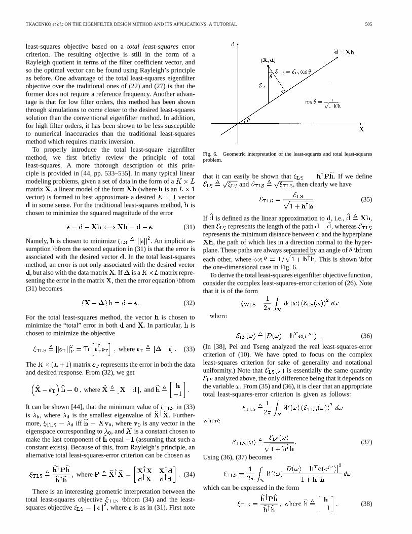
There is an interesting geometric interpretation between thetotal least-squares objective \bfrom (34) and the least-squares objective , where is as in (31). First note
Fig. 6. Geometric interpretation of the least-squares and total least-squaresproblem.
that it can easily be shown that . If we defineand , then clearly we have
(35)
If is defined as the linear approximation to, i.e., ,then represents the length of the path , whereasrepresents the minimum distance betweenand the hyperplane
, the path of which lies in a direction normal to the hyper-plane. These paths are always separated by an angle of\bfromeach other, where . This is shown \bforthe one-dimensional case in Fig. 6.
To derive the total least-squares eigenfilter objective function,consider the complex least-squares-error criterion of (26). Notethat it is of the form
(36)
(In [38], Pei and Tseng analyzed the real least-squares-errorcriterion of (10). We have opted to focus on the complexleast-squares criterion for sake of generality and notationaluniformity.) Note that is essentially the same quantity
analyzed above, the only difference being that it depends onthe variable . From (35) and (36), it is clear that an appropriatetotal least-squares-error criterion is given as follows:
(37)
Using (36), (37) becomes
which can be expressed in the form
(38)

506 IEEE TRANSACTIONS ON CIRCUITS AND SYSTEMS—II: ANALOG AND DIGITAL SIGNAL PROCESSING, VOL. 50, NO. 9, SEPTEMBER 2003
Fig. 7. (a) Magnitude responses of several low order low-pass filters. (N =
32, ! = 0:2�, ! = 0:3�) (b) Magnitude responses of several high orderlow-pass filters. (N = 148, ! = 0:25�, ! = 0:4�).
Here, is an matrix of the form
(39)
where , , and are, respectively, the , , and1 1 quantities
Thus, we have expressed as a Rayleigh quotient in termsof the vector . Note the similarities between the matrixfrom(39) and that from (34). By Rayleigh’s principle, we can find theoptimum and thus . To obtain the proper , we must scalethe optimum to satisfy (38).
The merits of the total least-squares eigenfilter methodare best seen via simulations. Following an example fromPei and Tseng [38], in Fig. 7(a) and (b), we have plottedthe magnitude response of several low-pass filters designedusing the traditional least-squares method, the conventionaleigenfilter method (which requires a reference frequency), andthe total least-squares eigenfilter method. The filters shown inFig. 7(a) are low order with parameters , ,and . For the conventional eigenfilter method, the
reference frequency was chosen to be . Though difficultto see, the total least-squares eigenfilter is noticably closer tothe optimal least-squares filter than the conventional eigenfilter.In fact, it is indistinguishable from the least-squares filter.Furthermore, the design complexity of the total least-squareseigenfilter is much less than that of the least-squares filter,which requires matrix inversion. The filters in Fig. 7(b) arehigh order with , , and( ). It can be observed that both eigenfilter methodsperformed about the same, whereas the least-squares filteryielded a poor response. The reason for this is that the matrixwhich needed to be inverted for the least-squares method wasextremely ill-conditioned. For this example, the conditionnumber was 1.7012 . Both eigenfilter methods, as theydo not require matrix inversion, are much less susceptible tonumerical inaccuracies caused by ill-conditioned matrices thanfilters designed using the least-squares method. This exampleserves to show the merits of the total least-squares eigenfiltermethod for both low order filters as well as high order ones.An extension of the total least-squares method was recentlyproposed by Zhang and Chen [54] which asymptoticallyapproaches the conventional least-squares solution.
D. Designing IIR Filters Using the Eigenfilter Method
1) Design of All-Pass Filters:Thus far, we only focusedon designing FIR filters using the eigenfilter method. Severalmethods for designing IIR filters have also been considered inthe literature. The first to consider this problem were Laaksoet al. [14] for the design of all-pass phase compensators. Peiand Shyu [33], as well as Nguyenet al. [22], later suggestedalternative design methods for these filters. Recently, Zhangand Iwakura [55] considered the design of phase equirippleall-pass filters based on an eigenfilter method. They showedthat the optimality criterion for the phase error in the Chebyshevsense could be posed as a generalized eigenvalue problem andproposed an iterative eigenfilter method to design equiripplephase responses. Here, we focus on the method of Pei and Shyuin [33], which is optimal with respect to its error criterion,which is a modification of the phase error norm. In contrast,the methods proposed in [14] and [22] are only approximationsto the phase error norm.
The transfer function of a causalth order all-pass functionis of the form [49]
where
and
Here, we will focus on real coefficient all-pass functions forwhich is real for all . In this case, is of the form
. By construction, the frequency re-sponse of is of unit magnitude, i.e., . Hence,the only design freedom present is in the selection of the phaseof . The phase of , which we denote here by
, is of the form
(40)
TKACENKO et al.: ON THE EIGENFILTER DESIGN METHOD AND ITS APPLICATIONS: A TUTORIAL 507
where is the phase of given by
(41)
Let and denote the desired phaseresponses for the all-pass filter and its corre-sponding denomiator polynomial . From (40), wehave . Pei and Shyu [33]considered choosing to match , which can beobtained from using the above formula.
In obtaining a criterion to choose the coefficients of the poly-nomial , Pei and Shyu noted that if was approxi-mately equal to , then heuristically we would have
Equivalently, we would have, using (41)
Defining the vectors shown at the bottom of the page, then wewould have approximately for all . To choose toensure this condition as best as possible, Pei and Shyu [33] con-sidered minimizing a mean-squared-error measure of the form
subject to a unit norm constraint on(namely ). Sincethe “desired response” of is 0, the error metric can beexpressed as a quadratic form in terms of. In particular, wehave
(42)
and so the optimal denominator coefficient vectorcan befound using Rayleigh’s principle as before.
One problem with designing IIR filters not present when de-signing FIR filters is that of stability [49]. In order to have acausal, stable transfer function, all of its poles must lie inside theunit circle. In general, this constraint is very difficult to enforce.However, for all-pass filters, often times it is possible to obtainstable solutions by imposing constraints on the desired phase re-sponse . The phase of a real coefficient all-pass filter
with poles inside the unit circle and poles out-side the unit circle satisfies [22]
Hence, for a stable all-pass filter of order, we have
(43)
where is the group delay of . It was observed byPei and Shyu [33], as well as by Nguyenet al.[22], that by con-straining the desired group delay response to satisfy(43), often times stable all-pass filters would be obtained. How-ever, enforcing (43) for does not guarantee stability.
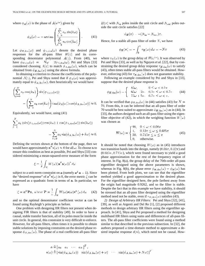
Following an example considered by Pei and Shyu in [33],suppose that the desired phase response is
.(44)
It can be verified that in (44) satisfies (43) for. From this, it can be inferred that an all-pass filter of order
70 would be best suited to approximate as in (44). In[33], the authors designed such an all-pass filter using the eigen-filter objective of (42), in which the weighing functionwas chosen as
otherwise.
(45)
It should be noted that choosing as in (45) introducestwo transition bands into the design, namely ( ) and( ), which were found necessary to yield a goodphase approximation for the rest of the frequency region ofinterest. In Fig. 8(a), the group delay of the 70th-order all-passeigenfilter designed using the above parameters is shown,whereas in Fig. 8(b), the phase error hasbeen plotted. From both plots, we can see that the eigenfiltermethod yielded a good approximation to the desired phase.For the eigenfilter designed here, the pole farthest away fromthe origin had magnitude 0.9262, and so the filter is stable.Despite the fact that in this example we have stability, it shouldbe stressed that an all-pass filter designed using the eigenfiltermethod need not be stable, even if satisfies (43).
2) Design of Arbitrary IIR Filters: Pei and Shyu [32], [41],[39], as well as Argenti and Del Re [1], [2] proposed differentmethods to design arbitrary IIR filters using the eigenfilter ap-proach. In [41], Shyu and Pei proposed a method for designingmultiband IIR filters using sums and differences of all-pass fil-ters. The all-pass filter coefficients were found using a methodsimilar to that described in the previous subsection. In [32], theauthors proposed a time-domain method to approximate a de-sired impulse response , which need not be causal. How-
508 IEEE TRANSACTIONS ON CIRCUITS AND SYSTEMS—II: ANALOG AND DIGITAL SIGNAL PROCESSING, VOL. 50, NO. 9, SEPTEMBER 2003
Fig. 8. (a) Group delay response of the all-pass eigenfilter. (b) Phase error� (!) � � (!). [N = 70,W (!) as in (45)].
ever, to get good performance, computations must be performedon matrices of very large sizes (in [32], matrices of size 512were used). Furthermore, there is no guarantee that the resultingfilter will be stable. In [39], Pei and Shyu considered the de-sign of special classes of IIR eigenfilters satisfying certain timeand frequency-domain constraints. Recently, Argenti and DelRe [1], [2] proposed an IIR eigenfilter design method using afrequency-domain approach which we present here.
Suppose that we have a causal IIR filter of the form
where and
Instead of choosing and to minimize the usualweighted mean-squared-error criterion of (26), which is diffi-cult to do, the authors of [1] and [2] proposed choosing them tominimize the following error measure:
where (46)
Heuristically, can be argued to be a valid error crite-rion, since if , then we should also have
and conversely. The advantagehere is that can be expressed as a quadratic form in termsof the polynomial coefficients, as we now show.
Define the following vectors:
It should be noted that here we define the vectorvector for any nonnegative integer. Clearly, we have
and . As such,from (46) is simply
Let us now define the following vectorobtained by concate-nating and :
Then we have
Using this in (46), we have
and hence is a quadratic form in terms of the vector ofnumerator and denominator coefficients. By subjectingto theusual unit norm condition , the optimal is obtainedusing Rayleigh’s principle.
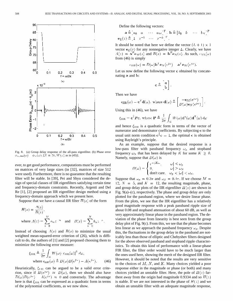
As an example, suppose that the desired response is alow-pass filter with passband frequency and stopbandfrequency that has been delayed by for some .Namely, suppose that is
don't care .
Suppose that and . If we choose, , and , the resulting magnitude, phase,
and group delay plots of the IIR eigenfilter are shown inFig. 9(a)–(c), respectively. The phase and group delay are onlyplotted for the passband region, where we desire linear phase.From the plots, we see that the IIR eigenfilter has a relativelygood magnitude response with a peak passband ripple size ofabout 0.08 and stopband attenuation of about 60 dB, as well asvery approximately linear phase in the passband region. The de-viation of the phase from linearity is best seen from the groupdelay plot of Fig. 9(c). From this, we see that the phase becomesless linear as we approach the passband frequency. Despitethis, the fluctuations in the group delay in the passband are not-icably less than those of elliptic and Chebyshev filters designedfor the above observed passband and stopband ripple character-istics. To obtain this kind of performance with a linear-phaseFIR filter, the filter order would have to be much larger thanthe ones used here, showing the merit of the designed IIR filter.However, it should be noted that the results are very sensitiveto the choices of , , and . Many choices yielded a poorresponse either in the magnitude or phase (or both) and manychoices yielded an unstable filter. Here, the pole of far-thest away from the origin had magnitude 0.9334 and sois stable. If we are not interested in the phase of and weobtain an unstable filter with an adequate magnitude response,

TKACENKO et al.: ON THE EIGENFILTER DESIGN METHOD AND ITS APPLICATIONS: A TUTORIAL 509
Fig. 9. (a) Magnitude response of the IIR low-pass eigenfilter. (b) Phase response in the passband region. (c) Group delay response in the passband region.(! = 0:3�, ! = 0:4�, M = 12,N = 5,K = 12).
then we can replace each pole outside the unit circle with its re-ciprocal conjugate pair. In [1], [2], Argenti and Del Re proposedan iterative equiripple eigenfilter technique to improve the mag-nitude characteristic of the filter in this case, which was shownto work well through simulations. However, since we often de-sire exact or approximate linear phase in practice, IIR eigenfil-ters have not been as widely used as their FIR counterparts.
E. Multidimensional Eigenfilters
The eigenfilter method can easily be extended to the multi-dimensional case. Nashashibi and Charalambous [18] were thefirst to design multidimensional eigenfilters by considering thetwo-dimensional (2-D) case. Most, if not all, contributions re-garding multidimensional eigenfilters have been for the 2-Dcase and have come from Pei and Shyu [26], [30], [31], [35],although others have also considered this problem, including T.Chen [10], as well as H. Chen and Ford [8]. Here, we focus onthe general -dimensional case by generalizing the objectivefunctions (22) and (27).
Suppose that we have an FIR-dimensional signal ,where is an -dimensional integer vector. By FIR, we meanthat is only nonzero for a finite number of integer vectors
. The frequency response of is a function ofvariables given by the following [49]:
(47)
where is a subset of the set of all -dimensional integervectors. Here, has finite cardinality and consists of thoseinteger vectors such that is nonzero. If has linearphase [49], then we have
where is a real constant vector and is a real -dimen-sional function of the form
(48)
where is, like , a subset (of finite cardinality) of the set ofall -D integer vectors, is a real sequence, and isa real function consisting of trigonometric functions (productsof sines and cosines in particular). Note that if we impose somesort of lexicographical ordering on the coefficients of for
as in (47) or for as in (48), then we have
(49)
where , , , and consist of the respective elementsof , , , and for appropriate arrangedaccording to some order.
If the goal is to design a filter to approximate a desiredresponse , then one approach is to choose the filtercoefficients to minimize either
(50)
if the desired response is a real function, or alternatively
(51)
if is complex. Note that and are simply -dimen-sional extensions of the objectives (22) and (27) previously con-sidered for the one-dimensional (1-D) case. Here, the region
in (50) is a subset of the -dimensional interval ,whereas in (51). Using the decompositions of
and from (49), it can be shown that we get theequations shown at the bottom of the page. Hence, by imposing
where
where
510 IEEE TRANSACTIONS ON CIRCUITS AND SYSTEMS—II: ANALOG AND DIGITAL SIGNAL PROCESSING, VOL. 50, NO. 9, SEPTEMBER 2003
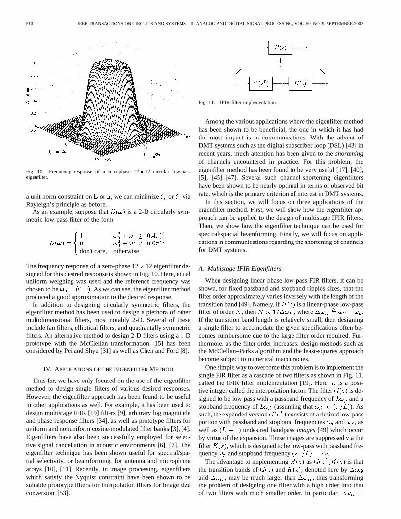
Fig. 10. Frequency response of a zero-phase 12� 12 circular low-passeigenfilter.
a unit norm constraint on or , we can minimize or viaRayleigh’s principle as before.
As an example, suppose that is a 2-D circularly sym-metric low-pass filter of the form
don't care otherwise.
The frequency response of a zero-phase 1212 eigenfilter de-signed for this desired response is shown in Fig. 10. Here, equaluniform weighing was used and the reference frequency waschosen to be . As we can see, the eigenfilter methodproduced a good approximation to the desired response.
In addition to designing circularly symmetric filters, theeigenfilter method has been used to design a plethora of othermultidimensional filters, most notably 2-D. Several of theseinclude fan filters, elliptical filters, and quadrantally symmetricfilters. An alternative method to design 2-D filters using a 1-Dprototype with the McClellan transformation [15] has beenconsidered by Pei and Shyu [31] as well as Chen and Ford [8].
IV. A PPLICATIONS OF THEEIGENFILTER METHOD
Thus far, we have only focused on the use of the eigenfiltermethod to design single filters of various desired responses.However, the eigenfilter approach has been found to be usefulin other applications as well. For example, it has been used todesign multistage IFIR [19] filters [9], arbitrary log magnitudeand phase response filters [34], as well as prototype filters foruniform and nonuniform cosine-modulated filter banks [3], [4].Eigenfilters have also been successfully employed for selec-tive signal cancellation in acoustic environments [6], [7]. Theeigenfilter technique has been shown useful for spectral/spa-tial selectivity, or beamforming, for antenna and microphonearrays [10], [11]. Recently, in image processing, eigenfilterswhich satisfy the Nyquist constraint have been shown to besuitable prototype filters for interpolation filters for image sizeconversion [53].
Fig. 11. IFIR filter implementation.
Among the various applications where the eigenfilter methodhas been shown to be beneficial, the one in which it has hadthe most impact is in communications. With the advent ofDMT systems such as the digital subscriber loop (DSL) [43] inrecent years, much attention has been given to theshorteningof channels encountered in practice. For this problem, theeigenfilter method has been found to be very useful [17], [40],[5], [45]–[47]. Several such channel-shortening eigenfiltershave been shown to be nearly optimal in terms of observed bitrate, which is the primary criterion of interest in DMT systems.
In this section, we will focus on three applications of theeigenfilter method. First, we will show how the eigenfilter ap-proach can be applied to the design of multistage IFIR filters.Then, we show how the eigenfilter technique can be used forspectral/spacial beamforming. Finally, we will focus on appli-cations in communications regarding the shortening of channelsfor DMT systems.
A. Multistage IFIR Eigenfilters
When designing linear-phase low-pass FIR filters, it can beshown, for fixed passband and stopband ripples sizes, that thefilter order approximately varies inversely with the length of thetransition band [49]. Namely, if is a linear-phase low-passfilter of order , then , where .If the transition band length is relatively small, then designinga single filter to accomodate the given specifications often be-comes cumbersome due to the large filter order required. Fur-thermore, as the filter order increases, design methods such asthe McClellan–Parks algorithm and the least-squares approachbecome subject to numerical inaccuracies.
One simple way to overcome this problem is to implement thesingle FIR filter as a cascade of two filters as shown in Fig. 11,called the IFIR filter implementation [19]. Here, is a posi-tive integer called the interpolation factor. The filter is de-signed to be low pass with a passband frequency of and astopband frequency of (assuming that ). Assuch, the expanded version consists of a desired low-passportion with passband and stopband frequenciesand , aswell as ( ) undesired bandpassimages[49] which occurby virtue of the expansion. These images are suppressed via thefilter , which is designed to be low-pass with passband fre-quency and stopband frequency .
The advantage to implementing as is thatthe transition bands of and , denoted here byand , may be much larger than , thus transformingthe problem of designing one filter with a high order into thatof two filters with much smaller order. In particular,

TKACENKO et al.: ON THE EIGENFILTER DESIGN METHOD AND ITS APPLICATIONS: A TUTORIAL 511
and , bothof which are larger than assuming .
In [9], Chen and Vaidyanathan showed how to design the filterfor the specifications of the original filter using the
eigenfilter method, assuming that the image suppressorhas already been designed. To properly describe their method,we must introduce a few new quantities. Suppose that issome Type I linear-phase filter of order for some even .Then
Using (8), we can express the’s in terms of the ’s. Ifis the vector of filter coefficients
of and , then is the foldedversion of and we have
(52)
where and are, respectively, theand matrices
(53)
where and denote, respectively, the identity andreversal matrices. With these definitions, we can now proceed toshow how to design for the specifications of usingthe eigenfilter approach.
Suppose that and are real Type 1 linear-phase fil-ters of orders and . Then clearly isalso a Type 1 linear-phase filter of order . Letand denote the vectors of coefficients of and , anddenote the folded versions of and by and . Recall thatthe original goal is to make a good low-pass narrowbandfilter. In [9], the authors considered choosing using theeigenfilter approach of Section II. Namely, the folded version(the same vector considered in Section II) was chosen mini-mize the objective with is as in (16), subject tothe usual unit-norm condition . It was shown that thisfilter design problem could be posed as an eigenfilter problem interms of the vector, the folded version of , as we now show.
First note that using (52) and (53). Then note thatthe coefficients of are obtained by inserting ( ) con-secutive zeros between each coefficient of . As such, ifdenotes the vector of coefficients of , then wehave , where is the matrix
Fig. 12. Magnitude response of a low-pass IFIR eigenfilter.
consisting of the ( ) identity matrix with ( ) rows ofzeros inserted between each row. For example
......
.... . .
...
Now note that the coefficients ofcan be expressed as , where is the
Toeplitz convolution matrix
......
. . ....
. . .
. . ....
......
. . .
consisting of the coefficients of the predesigned filter. Hence, the folded version of,
namely the vector , is given by the following:
With this, the objective function from (16) becomes
To avoid trivial solutions, we subject to the usual unit normconstraint . This shows that the eigenfilter problemfor the original can be posed as an eigenfilter problemfor the model filter . We should note that once the optimal
is found, the resulting solution should be scaled so that.
As an example (taken from [9]), suppose we wish to design alow-pass filter with and using the IFIReigenfilter approach. If we choose , , ,and (so that ), we obtain the magnitude responseshown in Fig. 12. Here, was chosen to be a low-pass filter

512 IEEE TRANSACTIONS ON CIRCUITS AND SYSTEMS—II: ANALOG AND DIGITAL SIGNAL PROCESSING, VOL. 50, NO. 9, SEPTEMBER 2003
with equal and maximal flatness at [49]. The resultingresponse has a passband ripple of and a stopbandripple of (or ). To obtain the samespecifications using a single eigenfilter would require an orderof 36 [9]. One advantage from using the IFIR approach comesin the savings from implementing in the cascade form
. As and are linear phase of orders 18and 6, we only require multipliersand adders using the IFIR implementation [49].In contrast, by using the single eigenfilter, we would require
multipliers and 36 adders.
B. Spectral/Spacial Beamforming
A common problem in array signal processing is thatof beamforming [13], in which a group of waves (such aselectromagnetic or audio) impinge upon an array of sensors(such as antennas or microphones) and the goal is to tune theoutput of these sensors to focus only on a specific set of wavescorresponding to a certain temporal frequency arriving froma certain spacial direction. For example, if a radio station istransmitting a signal in an environment with reflective pathsbetween the transmitter and antenna array at the receiver, thereceiver may wish to focus only on waves near the carrier fre-quency of the radio signal coming directly from the transmitter(following a path known as the line-of-sight path). It turnsout that for delay-and-sum beamformers [13], such as the arcarray with delay lines that we shall soon consider, the problemof steering the gain of the array to accept certain temporalfrequencies and spacial directions while rejecting others isanalogous to designing a filter to match a desired response. Asa result, the eigenfilter approach can be applied to the problemof beamforming.
Chen was the first to consider using the eigenfilter method forthe design of beamformers in [10]. In particular, he consideredthe design of an arc array with delay lines shown in Fig. 13.The array consists of sensors that are placed along a circleof radius . As can be seen in Fig. 13, theth sensor is at anangle with respect to a certain reference point and hasdelay lines attached to it. Each delay path is weighed by thequantity which is chosen at the receiver and used to steerthe beam or gain of the array to a desired response. Waves froma particular source impinging upon the array are assumed to bein the far field and arrive at the array at an angle ofas shown inFig. 13. The signals from the various sensors and delay paths arecombined to obtain a gain pattern given by the followingexpression:
where is the delay of theth tap of the th sensor dueto wave propagation and taps given by [10]
Here, is the speed of the wave in the given medium (suchas the speed of light or the speed of sound),is the radius
Fig. 13. Arc antenna array with delay lines.
Fig. 14. Magnitude of the gain pattern of an arc array with delay lines.
of the arc array, and is the length of the unit delay. If wedefine the weight vectorwhere the ’s are simply the ’s arranged ac-cording to some order and similarly define the vector
where the’s are just the ’s arranged according to the same
order, then the gain pattern can be expressed as
Analogous to the multidimensional objective of (51), Chenchose to make best approximate a desired gainscaled by a factor , where is some referencepoint. Namely, was chosen to minimize
As , we clearly have
TKACENKO et al.: ON THE EIGENFILTER DESIGN METHOD AND ITS APPLICATIONS: A TUTORIAL 513
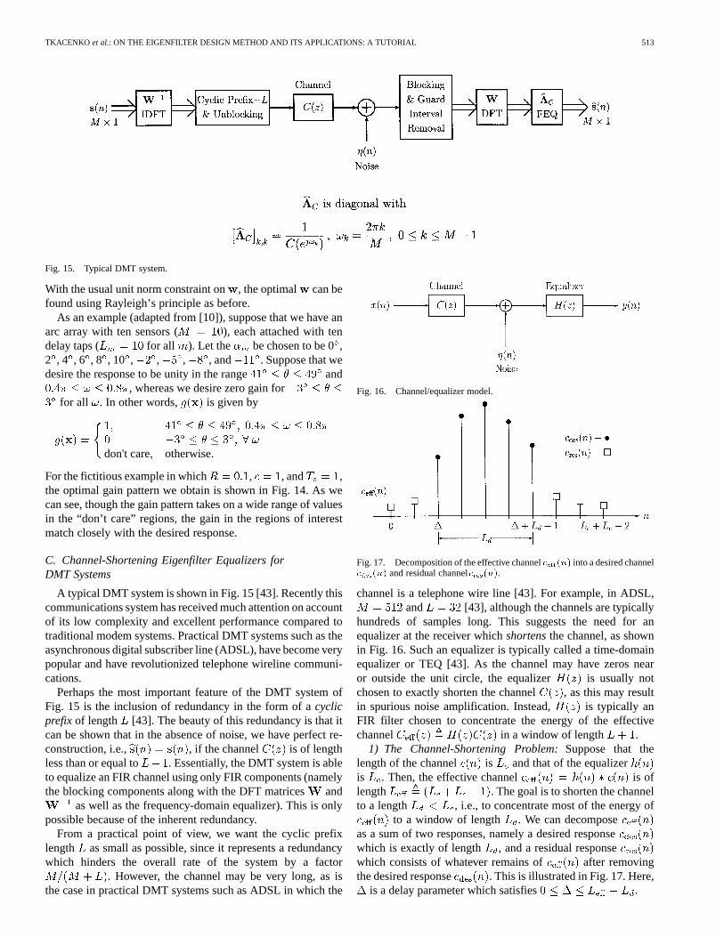
Fig. 15. Typical DMT system.
With the usual unit norm constraint on, the optimal can befound using Rayleigh’s principle as before.
As an example (adapted from [10]), suppose that we have anarc array with ten sensors ( ), each attached with tendelay taps ( for all ). Let the be chosen to be 0,2 , 4 , 6 , 8 , 10 , , , , and . Suppose that wedesire the response to be unity in the range and
, whereas we desire zero gain forfor all . In other words, is given by
don't care otherwise.
For the fictitious example in which , , and ,the optimal gain pattern we obtain is shown in Fig. 14. As wecan see, though the gain pattern takes on a wide range of valuesin the “don’t care” regions, the gain in the regions of interestmatch closely with the desired response.
C. Channel-Shortening Eigenfilter Equalizers forDMT Systems
A typical DMT system is shown in Fig. 15 [43]. Recently thiscommunications system has received much attention on accountof its low complexity and excellent performance compared totraditional modem systems. Practical DMT systems such as theasynchronous digital subscriber line (ADSL), have become verypopular and have revolutionized telephone wireline communi-cations.
Perhaps the most important feature of the DMT system ofFig. 15 is the inclusion of redundancy in the form of acyclicprefix of length [43]. The beauty of this redundancy is that itcan be shown that in the absence of noise, we have perfect re-construction, i.e., , if the channel is of lengthless than or equal to . Essentially, the DMT system is ableto equalize an FIR channel using only FIR components (namelythe blocking components along with the DFT matricesand
as well as the frequency-domain equalizer). This is onlypossible because of the inherent redundancy.
From a practical point of view, we want the cyclic prefixlength as small as possible, since it represents a redundancywhich hinders the overall rate of the system by a factor
. However, the channel may be very long, as isthe case in practical DMT systems such as ADSL in which the
Fig. 16. Channel/equalizer model.
Fig. 17. Decomposition of the effective channelc (n) into a desired channelc (n) and residual channelc (n).
channel is a telephone wire line [43]. For example, in ADSL,and [43], although the channels are typically
hundreds of samples long. This suggests the need for anequalizer at the receiver whichshortensthe channel, as shownin Fig. 16. Such an equalizer is typically called a time-domainequalizer or TEQ [43]. As the channel may have zeros nearor outside the unit circle, the equalizer is usually notchosen to exactly shorten the channel , as this may resultin spurious noise amplification. Instead, is typically anFIR filter chosen to concentrate the energy of the effectivechannel in a window of length .
1) The Channel-Shortening Problem:Suppose that thelength of the channel is and that of the equalizeris . Then, the effective channel is oflength . The goal is to shorten the channelto a length , i.e., to concentrate most of the energy of
to a window of length . We can decomposeas a sum of two responses, namely a desired responsewhich is exactly of length , and a residual responsewhich consists of whatever remains of after removingthe desired response . This is illustrated in Fig. 17. Here,
is a delay parameter which satisfies .

514 IEEE TRANSACTIONS ON CIRCUITS AND SYSTEMS—II: ANALOG AND DIGITAL SIGNAL PROCESSING, VOL. 50, NO. 9, SEPTEMBER 2003
Melsaet al.[17], chose the equalizer coefficients to minimizethe energy of the residual response subject to keeping theenergy of the desired response at unity. As we now show,this problem can be posed as an eigenfilter problem. Define thefollowing vectors and matrices:
......
.. ....
. . .
. . ....
......
. . .
Here, , , and are, respectively, , , and. By the convolution
(54)
Now define the following vectors and , as well as thewindowing matrices and , as shown in the equationat the bottom of the page. Here, and are ,whereas and are . Clearly, we have
and , where wehave used the convolution equation of (54). The energy of thedesired and residual responses, which we denote here, respec-tively, by and , are simply the following:
Here we have used the fact that and
. Hence, the design problem considered byMelsa et al. [17] is tantamount to the following problem:
(55)
where and are Hermitian positive semidefinite matrices.To show that the problem of (55) can be posed as a traditionaleigenfilter problem, we perform a Cholesky decomposition ofthe matrix [12]. Assuming that the matrix is positive def-inite, then it admits a Cholesky-like decomposition of the form[12]
where is a squarenonsingularmatrix. If we define the vector, so that , then as varies over all nonzero
vectors, will as well. Hence, the problem in (55) is equivalentto
Minimize subject to
where
This problem (in terms of the vector) is in fact the eigenfilterproblem, which can be solved via Rayleigh’s principle as be-fore. Once the optimal is found, the optimal is found using
. If the matrix is strictly positive semidefinite, theoriginal optimization problem of (55) can still be posed as aneigenfilter problem [17]; however, the method by which this isdone is much more complicated.
The method for channel shortening given in (55) is knownas the maximum shortening signal-to-noise ratio (MSSNR)method [5], since it maximizes the shortening signal-to-noiseratio defined by
In Fig. 18, the impulse response of a typical channel encoun-tered in a DMT system is shown, along with the equalized ef-fective channel designed using the MSSNR method. Here, thechannel is carrier-service area (CSA) loop # 1, a common sub-scriber loop encountered in an ADSL system [43]. The channelis of length , the equalizer is of length 16, and the de-sired length is (corresponding to a cyclic prefix lengthof 32). Here, the optimal equalizer was calculated for allinthe range and the actual used was the one whichyielded the largest SSNR. As can be seen, the effective channelappears to be “shortened” to the desired length. In this example,the best equalizer occured whenwas 25 corresponding to aSSNR of 33.3312 dB.

TKACENKO et al.: ON THE EIGENFILTER DESIGN METHOD AND ITS APPLICATIONS: A TUTORIAL 515
Fig. 18. Impulse responses of the original channelc(n) and the equalizedchannelc (n). (L = 512, L = 16, L = 33, � = 25, SSNR =33:3312 dB).
Several generalizations of the MSSNR method for channelshortening have been proposed recently. In [47], the authorsproposed a method to jointly shorten the channel and suppressthe noise power observed after equalization, whereas in [45],a similar method was proposed requiring only one Choleskydecomposition (i.e., the decomposition did not depend on thedelay parameter ). Recently, a novel eigenfilter method calledthe minimum intersymbol interference (min-ISI) method wasproposed by Arslanet al. [5], which exploited the DMT sub-channels which cannot be used to improve the DMT channelsused for joint channel shortening and noise suppression. Sim-ulation results have shown that these methods perform nearlyoptimally in terms of observed bit rate (the primary figure ofmerit for DMT systems), especially the min-ISI method.
V. CONCLUDING REMARKS
The eigenfilter method has been shown to possess severaladvantages over other traditional filter design methods. As op-posed to the least-squares approach, which requires the compu-tation of a matrix inverse which may be susceptible to numer-ical inaccuracies, the eigenfilter method has a much lower de-sign complexity and remains robust even when ill-conditionedmatrices are present in the design problem. In contrast to theMcClellan–Parks algorithm, which is difficult to modify for cer-tain design criteria, the eigenfilter method can easily be modi-fied to satisfy a plethora of design constraints. Such advantages,when coupled together with the good performance of eigenfiltermethod, make it an attractive method to use for filter design.
In addition to its numerous strengths, the eigenfilter methodwas shown to be useful in a variety of applications, since manydesign problems can be posed as an eigenfilter problem. Here,the method was shown to be useful for designing model filtersfor multistage IFIR filters, which are useful when narrow transi-tion bands are required. Also, the eigenfilter method was shownto be applicable to the problem of spectral/spacial filtering orbeamforming for sensor arrays, in which we wish to focus ontemporal frequencies in a particular band arriving from a par-ticular spacial direction. Finally, the method was found to beuseful for the design of channel-shortening equalizers, whichare commonly needed in popular communications systems suchas ADSL.
The eigenfilter method continues to find applications inseveral areas of research. Recently, the eigenfilter method
for channel shortening was extended for the design offractionally spaced equalizers [45], [47] as well as for de-signing channel-shortening equalizers for multiple-inputmultiple-output (MIMO) channels [46]. In addition, the eigen-filter method has been shown to appear in the design of certainoptimum compaction filters [51]. Current open problems infilter bank theory include using the eigenfilter method to designFIR compaction filters, using IFIR eigenfilters as compactionfilters, and using the eigenfilter method to design optimal filterbanks. As can be seen, on account of its numerous merits,together with the myriad of design problems to which it canbe applied, the eigenfilter method is and will continue to be aversatile design algorithm.
SELECTED REFERENCES BYTOPIC
Early Works on Eigenfilters:[42] D. Slepian, 1978[50] P. P. Vaidyanathan and T. Q. Nguyen, 1987[18] A. Nashashibi and C. Charalambous, 1988[24] S. C. Pei and J. J. Shyu, 1988
Arbitrary Desired Response Eigenfilters:[20] T. Q. Nguyen, 1991[29] S. C. Pei and J. J. Shyu, 1993[21] T. Q. Nguyen, 1993
All-Pass Eigenfilters:[14] T. I. Laakso, T. Q. Nguyen, and R. D. Koilpillai, 1993[33] S. C. Pei and J. J. Shyu, 1994[22] T. Q. Nguyen, T. I. Laakso, and R. D. Koilpillai, 1994[55] X. Zhang and H. Iwakura, 1999
IIR Eigenfilters:[41] J. J. Shyu and S. C. Pei, 1992[32] S. C. Pei and J. J. Shyu, 1994[1] F. Argenti and E. Del Re, 1998[2] F. Argenti and E. Del Re, 1998[39] S. C. Pei, C. C. Hsu, and P. H. Wang, 2002
Multidimensional Eigenfilters:[18] A. Nashashibi and C. Charalambous, 1988[26] S. C. Pei and J. J. Shyu, 1990[30] S. C. Pei and J. J. Shyu, 1993[10] T. Chen, 1993[31] S. C. Pei and J. J. Shyu, 1993[35] S. C. Pei and J. J. Shyu, 1994[8] H. Chen and G. E. Ford, 1996
Applications in Spectral/spacial Filtering or Beamforming:[10] T. Chen, 1993[6] S. Bharitkar and C. Kyriakakis, 2000[7] S. Bharitkar and C. Kyriakakis, 2001[11] S. Doclo and M. Moonen, 2002
Applications in Channel-Shortening Equalizer Design:[17] P. J. W. Melsa, R. C. Younce, and C. E. Rohrs, 1996[40] R. Schur and J. Speidel, 2001[5] G. Arslan, B. L. Evans, and S. Kiaei, 2001[45] A. Tkacenko and P. P. Vaidyanathan, 2002[46] A. Tkacenko and P. P. Vaidyanathan, 2002[47] A. Tkacenko and P. P. Vaidyanathan, 2002
516 IEEE TRANSACTIONS ON CIRCUITS AND SYSTEMS—II: ANALOG AND DIGITAL SIGNAL PROCESSING, VOL. 50, NO. 9, SEPTEMBER 2003
REFERENCES
[1] F. Argenti and E. D. Re, “Design of IIR eigenfilters with arbitrarymagnitude frequency response,”Proc. IEEE ICASSP ’98, vol. 3, pp.1265–1268, 1998.
[2] , “Design of IIR eigenfilters in the frequency domain,”IEEE Trans.Signal Processing, vol. 46, pp. 1694–1698, June 1998.
[3] , “Eigenfilter design of real and complex coefficient prototypes foruniform and nonuniform filter banks,”Proc. IEEE ICASSP ’99, vol. 3,pp. 1477–1480, 1999.
[4] , “Eigenfilter design of real and complex coefficient QMFprototypes,” IEEE Trans. Circuits Syst. II, vol. 47, pp. 787–792,Aug. 2000.
[5] G. Arslan, B. L. Evans, and S. Kiaei, “Equalization for discrete multitonetransceivers to maximize bit rate,”IEEE Trans. Signal Processing, vol.49, pp. 3123–3135, Dec. 2001.
[6] S. Bharitkar and C. Kyriakakis, “Eigenfilters for signal cancellation,”Proc. IEEE ISPACS ’00, 2000.
[7] , “Correlation and spatial sensitivity of eigenfilters for selectivesignal cancellation in multiple-listener environments,” inProc. AsilomarConf. Signals, Systems, and Computers, vol. 2, Monterey, CA, Nov.2001, pp. 1578–1582.
[8] H. Chen and G. E. Ford, “A unified eigenfilter approach to the design oftwo-dimensional zero-phase FIR filters with the Mcclellan transform,”IEEE Trans. Circuits Syst. II, vol. 43, pp. 622–626, Aug. 1996.
[9] T. Chen and P. P. Vaidyanathan, “Design of IFIR eigenfilters,”Proc.IEEE ISCAS ’91, vol. 1, pp. 264–267, 1991.
[10] T. Chen, “Unified eigenfilter approach: With applications to spec-tral/spatial filtering,” Proc. IEEE ISCAS ’93, vol. 1, pp. 331–334,1993.
[11] S. Doclo and M. Moonen, “Comparison of least-squares and eigenfiltertechniques for broadband beamforming,”Proc. 3rd IEEE SPS-2002, pp.73–76, 2002.
[12] R. A. Horn and C. R. Johnson,Matrix Analysis. Cambridge, U.K:Cambridge Univ. Press, 1985.
[13] D. H. Johnson and D. E. Dudgeon,Array Signal Pro-cessing. Englewood Cliffs, NJ: Prentice-Hall, Inc., 1993.
[14] T. I. Laakso, T. Q. Nguyen, and R. D. Koilpillai, “Designing allpassfilters using the eigenfilter method,”Proc. IEEE ICASSP ’93, vol. 3,pp. 77–80, 1993.
[15] J. H. McClellan, “The design of 2-D digital filters by transformations,”in Proc. 7th Annu. Princeton Conf. Information Science and Systems,1973, pp. 247–251.
[16] J. H. McClellan and T. Parks, “A unified approach to the design of op-timum FIR linear-phase digital filters,”IEEE Trans. Circuit Theory, vol.CT-20, pp. 697–701, Nov. 1973.
[17] P. J. W. Melsa, R. C. Younce, and C. E. Rohrs, “Impulse response short-ening for discrete multitone transceivers,”IEEE Trans. Commun., vol.44, pp. 1662–1672, Dec. 1996.
[18] A. Nashashibi and C. Charalambous, “2-D FIR eigenfilters,”Proc. IEEEISCAS ’88, vol. 2, pp. 1037–1040, 1988.
[19] Y. Neuvo, C. Y. Dong, and S. K. Mitra, “Interpolated finite impulseresponse filters,”IEEE Trans. Acoust., Speech, Signal Processing, pp.563–570, June 1984.
[20] T. Q. Nguyen, “The eigenfilter for the design of linear-phase filterswith arbitrary magnitude response,”Proc. IEEE ICASSP ’91, vol. 3,pp. 1981–1984, 1991.
[21] , “The design of arbitrary FIR digital filters using the eigenfiltermethod,”IEEE Trans. Signal Processing, vol. 41, pp. 1128–1139, Mar.1993.
[22] T. Q. Nguyen, T. I. Laakso, and R. D. Koilpillai, “Eigenfilter approachfor the design of allpass filters approximating a given phase response,”IEEE Trans. Signal Processing, vol. 42, pp. 2257–2263, Sept. 1994.
[23] M. Okuda, M. Ikehara, and S. Takahashi, “Fast and stable least-squaresapproach for the design of linear phase FIR filters,”IEEE Trans. SignalProcessing, vol. 46, pp. 1485–1493, June 1998.
[24] S. C. Pei and J. J. Shyu, “Design of FIR Hilbert transformers anddifferentiators by eigenfilter,”IEEE Trans. Circuits Syst., vol. 35, pp.1457–1461, Nov. 1988.
[25] , “Eigenfilter design of higher-order digital differentiators,”IEEETrans. Acoust., Speech, Signal Processing, vol. 37, no. 4, pp. 505–511,Apr. 1989.
[26] , “2-D FIR eigenfilters: A least-squares approach,”IEEE Trans.Circuits Syst., vol. 37, pp. 24–34, Jan. 1990.
[27] , “Eigen-approach for designing FIR filters and all-pass phaseequalizers with prescribed magnitude and phase response,”IEEE Trans.Circuits Syst. II, vol. 39, pp. 137–145, Mar. 1992.
[28] , “Analytic closed forms for designing higher order digital differen-tiators by eigen-approach,”Proc. IEEE ISCAS ’92, vol. 2, pp. 573–576,1992.
[29] , “Complex eigenfilter design of arbitrary complex coefficient FIRdigital filters,” IEEE Trans. Circuits Syst. II, vol. 40, pp. 32–40, Jan.1993.
[30] , “Design of two-dimensional FIR eigenfilters for sampling-struc-ture conversion,”IEEE Trans. Circuits Syst. Video Technol., vol. 3, pp.158–162, Apr. 1993.
[31] , “Design of 2-D FIR digital filters by Mcclellan transformation andleast squares eigencontour mapping,”IEEE Trans. Circuits Syst. II, vol.40, pp. 546–555, Sept. 1993.
[32] , “Design of 1-D and 2-D IIR eigenfilters,”IEEE Trans. Signal Pro-cessing, vol. 42, pp. 962–966, Apr. 1994.
[33] , “Eigenfilter design of 1-D and 2-D IIR digital all-pass filters,”IEEE Trans. Signal Processing, vol. 42, pp. 966–968, Apr. 1994.
[34] , “Design of arbitrary FIR log eigenfilters,”IEEE Trans. CircuitsSyst. II, vol. 41, pp. 361–364, May 1994.
[35] , “A unified approach to the design of quadrantally symmetriclinear-phase two-dimensional FIR digital filters by eigenfilter ap-proach,”IEEE Trans. Signal Processing, vol. 42, pp. 2886–2890, Oct.1994.
[36] , “Analytic closed-form matrix for designing higher order digitaldifferentiators using eigen-approach,”IEEE Trans. Signal Processing,vol. 44, no. 3, pp. 698–701, Mar. 1996.
[37] S. C. Pei, C. C. Tseng, and W. S. Yang, “FIR filter design with linearconstraints using the eigenfilter approach,”IEEE Trans. Circuits Syst.II , vol. 45, pp. 232–237, Feb. 1998.
[38] S. C. Pei and C. C. Tseng, “A new eigenfilter based on total least squareserror criterion,”IEEE Trans. Circuits Syst. I, vol. 48, pp. 699–709, June2001.
[39] S. C. Pei, C. C. Hsu, and P. H. Wang, “Design of a class of IIR eigenfil-ters with time- and frequency-domain constraints,”IEEE Trans. CircuitsSyste. II, vol. 49, pp. 145–151, Feb. 2002.
[40] R. Schur and J. Speidel, “An efficient equalization method to minimizedelay spread in OFDM/DMT systems,”Proc. IEEE ICC ’01, vol. 1, pp.1–5, Jun. 2001.
[41] J. J. Shyu and S. C. Pei, “Design of IIR multi-band filters using IIRall-pass eigenfilters,” inProc. 35th Midwest Symp. Circuits and Systems,vol. 1, Aug. 1992, pp. 601–604.
[42] D. Slepian, “Prolate spheroidal wave functions, Fourier analysis, anduncertainty – V: The discrete case,”Bell Sys. Tech. J., vol. 57, pp.1371–1430, May-June 1978.
[43] T. Starr, J. M. Cioffi, and P. J. Silverman,Understanding Digital Sub-scriber Line Technology. Englewood Cliffs, NJ: Prentice-Hall, 1999.
[44] C. W. Therrien,Discrete Random Signals and Statistical Signal Pro-cessing. Englewood Cliffs, NJ: Prentice-Hall, 1992.
[45] A. Tkacenko and P. P. Vaidyanathan, “Noise optimized eigenfilter designof time-domain equalizers for DMT systems,”Proc. IEEE ICC ’02, Apr.2002.
[46] , “Eigenfilter design of mimo equalizers for channel shortening,”Proc. IEEE ICASSP ’02, May 2002.
[47] , “A new eigenfilter based method for optimal design of channelshortening equalizers,” Proc. IEEE ISCAS ’02, May 2002, submittedfor publication.
[48] D. W. Tufts and J. T. Francis, “Designing digital lowpass filters: Compar-ison of some methods and criteria,”IEEE Trans. Audio Electroacoust.,vol. AU-18, pp. 487–494, Dec. 1970.
[49] P. P. Vaidyanathan,Multirate Systems and Filter Banks. EnglewoodCliffs, NJ: Prentice-Hall, 1993.
[50] P. P. Vaidyanathan and T. Q. Nguyen, “Eigenfilters: A new approach toleast-squares FIR filter design and applications including Nyquist fil-ters,” IEEE Trans. Circuits Syst., vol. 34, pp. 11–23, Jan. 1987.
[51] P. P. Vaidyanathan, “Theory of optimal orthonormal subband coders,”IEEE Trans. Signal Processing, vol. 46, pp. 1528–1543, June 1998.
[52] Y. Wisutmethangoon and T. Q. Nguyen, “A method for design ofM th-band filters,” IEEE Trans. Signal Processing, vol. 47, pp.1669–1678, June 1999.
[53] S. Yang and T. Q. Nguyen, “InterpolatedM th-band filters for image sizeconversion,”IEEE Trans. Signal Processing, vol. 50, pp. 3028–3035,Dec. 2002.
[54] C. Zhang and T. Chen, “Toward optimal least square filters using theeigenfilter approach,”Proc. IEEE ICASSP ’02, vol. 4, pp. 4171–4174,2002.
[55] X. Zhang and H. Iwakura, “Design of IIR digital allpass filters basedon eigenvalue problem,”IEEE Trans. Signal Processing, vol. 47, pp.554–559, Feb. 1999.

TKACENKO et al.: ON THE EIGENFILTER DESIGN METHOD AND ITS APPLICATIONS: A TUTORIAL 517
Andre Tkacenko (S’00) was born in Santa Clara,CA, on February 24, 1977. He received the B.S. andM.S. degrees in electrical engineering from the Cali-fornia Institute of Technology (Caltech), Pasadena, in1999 and 2001, respectively. He is currently workingtoward the Ph.D. degree in the field of digital signalprocessing at Caltech.
In 1999, he was awarded the Graduate DivisionFellowship from Caltech. His research interestsinclude multirate systems, wavelet transforms, andtheir applications in digital communications and
data compression.
P. P. Vaidyanathan (S’80-M’83-SM’88-F’91) wasborn in Calcutta, India, on Oct. 16, 1954. He receivedthe B.Sc. (Hons.) degree in physics and the B.Tech.and M.Tech. degrees in radiophysics and electronics,all from the University of Calcutta, Calcutta, India, in1974, 1977, and 1979, respectively, and the Ph.D de-gree in electrical and computer engineering from theUniversity of California at Santa Barbara in 1982.
He was a post-doctoral fellow at the University ofCalifornia, Santa Barbara, from September 1982 toMarch 1983. In March 1983 he joined the Electrical
Engineering Department, Calfornia Institute of Technology, Pasadena, as an As-sistant Professor, and since 1993 has been Professor of Electrical Engineeringthere. He is the author of the bookMultirate Systems and Filter Banks(Engle-wood Cliffs, NJ: Prentice Hall, 1993). He has written several chapters for var-ious signal processing handbooks and has authored a number of papers in IEEEjournals. His main research interests are in digital signal processing, multiratesystems, wavelet transforms, and signal processing for digital communications.
Dr. Vaidyanathan was an Associate Editor for the IEEE TRANSACTIONS ON
CIRCUITS AND Systems during 1985–1987, and is currently an Associate Ed-itor for IEEE Signal Processing Letters, and a Consulting Editor forAppliedand Computational Harmonic Analysis. In 1998, he was a Guest Editor for spe-cial issues of the IEEE TRANSACTIONS ONSIGNAL PROCESSINGand the IEEETRANSACTIONS ONCIRCUITS AND SYSTEMS—II: A NALOG AND DIGITAL SIGNAL
PROCESSING, on the topics of filter banks, wavelets, and subband coders. Heserved as Vice Chairman of the Technical Program Committee for the 1983IEEE International symposium on Circuits and Systems, and as the TechnicalProgram Chairman for the 1992 IEEE International Symposium on Circuits andSystems. He was a recepient of the Award for Excellence in Teaching at theCalifornia Institute of Technology in 1983–1984, 1992–1993, and 1993–1994.He also received the National Science Foundation’s Presidential Young Investi-gator Award in 1986, the IEEE Acoustics, Speech, and Signal Processing SeniorAward for his paper on multirate perfect-reconstruction filter banks in 1989, andthe S. K. Mitra Memorial Award from the Institute of Electronics and Telecom-muncations Engineers, India, for his joint paper in the IETE Journal in 1990.He was also the coauthor of a paper on linear-phase perfect reconstruction filterbanks in the IEEE SP Transactions, for which the first author (Truong Nguyen)received the Young outstanding author award in 1993. Dr. Vaidyanathan waselected Fellow of the IEEE in 1991. He received the 1995 F. E. Terman Award ofthe American Society for Engineering Education, sponsored by Hewlett PackardCompany, for his contributions to engineering education, especially the bookMultirate systems and filter banks published by Prentice Hall in 1993. He hasgiven several plenary talks including at the Sampta’01, Eusipco’98, SPCOM’95,and Asilomar’88 conferences on signal processing. He has been chosen a distin-guished lecturer for the IEEE Signal Processing Society for the year 1996-97. In1999 he was chosen to receive the IEEE CAS Society’s Golden Jubilee Medal.He is a recepient of the IEEE Signal Processing Society’s Technical Achieve-ment Award for the year 2002.
Truong Q. Nguyen (S’85–M’85–SM’95) received the B.S., M.S., and Ph.Ddegrees in electrical engineering from the California Institute of Technology,Pasadena, in 1985, 1986 and 1989, respectively.
He was with MIT Lincoln Laboratory, Lexington, MA, from June 1989 to July1994, as a Member of Technical Staff. During the academic year 1993-1994, hewas a Visiting Lecturer at MIT and an Adjunct Professor at Northeastern Uni-versity, Boston, MA. From August 1994 to July 1998, he was with the Electricaland Computer Engineering Department, University of Wisconsin, Madison. Hewas with Boston University, Boston, MA, from August 1996 to June 2001. Heis currently a Professor at the Electrical and Computer Engineering Department,University of California at San Diego. He is coauthor (with Prof. G. Strang) ofthe textbookWavelets and Filter Banks(Wellesley, MA: Wellesley-CambridgePress, 1997) and the author of several matlab-based toolboxes on image com-pression, electrocardiogram compression, and filter bank design. He has pub-lished over 100 publications. He is currently the Series Editor (Digital SignalProcessing) for Academic Press. His research interests include video processingalgorithms and their efficient implementation.
Dr. Nguyen served as an Associate Editor for the IEEE TRANSACTIONS ON
SIGNAL PROCESSINGfrom 1994-1996 and for the IEEE TRANSACTIONS ON
CIRCUITS AND SYSTEMS from 1996-1997. He is currently an Associate Editorfor the IEEE TRANSACTIONS ON IMAGE PROCESSING, IEEE TRANSACTIONS
ON CIRCUITS AND SYSTEMS—II: A NALOG AND DIGITAL SIGNAL PROCESSING,and IEEE Signal Processing Letters. He received the IEEE TRANSACTIONS
ON SIGNAL PROCESSINGPaper Award (in the image and multidimensionalprocessing area) for the paper he co-wrote with Prof. Vaidyanathan onlinear-phase perfect-reconstruction filter banks in 1992 and the NationalScience Foundation Career Award in 1995.