operating manual em ace600 - biomarker
TRANSCRIPT

From Eye to Insight
OPERATING MANUAL EM ACE600167202032 Version 01/19

Important Note
Leica Mikrosysteme GmbH reserves the right to change technical specifications as well as manufacturing processes without prior notice. Only in this way is it possible to con-tinuously improve the technology and manufacturing techniques used to provide our customers with excellent products.
Any copyrights of this document are retained by Leica Mikrosysteme GmbH, Vienna. Any reproduction of text and illustrations (or any parts thereof) by printing, photocopy-ing, or other methods (including electronic systems and media) requires express prior permission in writing.
Issued by:
Leica Mikrosysteme GmbH Hernalser Hauptstrasse 219A-1170 Vienna

Leica EM ACE600Operating Manual
Leica EM ACE600 Serial Number:
Date of purchase:
For the instrument serial number, please refer to the name type label on the back of the instrument!
Please read this instruction manual carefully before operating the instrument.For Research use only!


Operating Manual Leica EM ACE600 Version 01/19 Page 1
Foreword
Please read this instruction manual carefully before operating the instrument. This user manual is intended to provide essential information about the Leica EM ACE600 coating system. It includes important information regarding correct operation, servicing, and troubleshooting. Following these instructions will help prevent hazards, reduce repair and downtime costs, and prolong the system's life.
The Leica EM ACE600 coater system can be handled safely and easily when operated in accordance to the instructions in this manual. Ignoring safety instructions may endanger the user(s) and the system itself.
Users must familiarize themselves with the system before operation. Special attention must be paid to comply with the safety requirements. The Leica EM ACE600 must not be used beyond the limits specified in the provided technical data sheet.
When hazardous substances (e.g. radioactive, toxic, or explosive substances) are processed, the substance-specific safety precautions must be implemented. It is forbidden to process substances that release corrosive or poisonous gases when they are subjected to vacuum and/or coating procedures.
Warranty claims will only be considered if the instrument is used according to the guidelines specified in this user manual.
In addition, all generally applicable legal and otherwise binding regulations for accident and environmental protection must be observed and communicated.
Leica reserves the right to change technical specifications as well as manufacturing processes without prior notice. Only in this way, Leica can continuously improve the technology and manufacturing techniques used to provide its customers with excellent products.
Any copyrights of this document are retained by Leica Mikrosysteme GmbH, Vienna. Any reproduction of text and illustrations (or any parts thereof) by printing, photocopying, or other methods (including electronic systems and media) as well as handing over to third parties requires approval of Leica Mikrosysteme GmbH.

Operating Manual Leica EM ACE600 Version 01/19 Page 2
Table of Contents
1. Introduction ..................................................................................................................... 4
1.1 Identification .................................................................................................................. 6 1.1.1 Product ................................................................................................................................ 6 1.1.2 Name and address of the manufacturer .............................................................................. 6
2. Product description ........................................................................................................ 7
2.1 Field of application and proper use ............................................................................... 7
2.2 Dimensions and weight ................................................................................................. 8
2.3 Environmental conditions for operation and storage .................................................... 8
2.4 Safety information ......................................................................................................... 9 2.4.1 General instructions ............................................................................................................. 9 2.4.2 Safety measures at the installation site ............................................................................. 10 2.4.3 Qualification of operating personnel .................................................................................. 10 2.4.4 Residual hazards ............................................................................................................... 10 2.4.5 Safety measures when working with nitrogen ................................................................... 11 2.4.6 Emergency procedure ....................................................................................................... 15
3. Installation and set up .................................................................................................. 15
3.1. Warranty ..................................................................................................................... 15
3.2. Instrument overview .................................................................................................... 16
3.3. Delivery of the instrument ........................................................................................... 17
3.4. Installation requirements for the instrument ................................................................ 17
3.5. Unpacking and connection ......................................................................................... 18
3.6 Inserting chamber shielding ........................................................................................ 22
3.7 Shutter installation ...................................................................................................... 26
3.8. Quartz crystal measurement installation ..................................................................... 28 3.8.1 Eccentric quartz holder ...................................................................................................... 30
3.9. Stage installation ........................................................................................................ 32 3.9.1 Rotating stage .................................................................................................................... 35
4. Operating instructions .................................................................................................. 37
4.1 General functions ........................................................................................................ 38 4.1.2 Software update................................................................................................................. 42
4.2 Pump and Vent ........................................................................................................... 44
4.3 Vacuum test ................................................................................................................ 45
4.4 Process start and stop ................................................................................................ 45
4.5 Thickness monitoring and geometrical correction (QSG) ........................................... 45
4.6 Carbon thread coating ................................................................................................ 46 4.6.1 Loading a carbon thread .................................................................................................... 47 4.6.2 Choosing a carbon thread protocol ................................................................................... 51

Operating Manual Leica EM ACE600 Version 01/19 Page 3
4.6.3 Carbon thread materials .................................................................................................... 53
4.7 Sputter coating ............................................................................................................ 54 4.7.1 Loading the sputter target .................................................................................................. 55 4.7.2 Choosing a sputtering protocol .......................................................................................... 57 4.7.3 Parameters for sputter coating .......................................................................................... 60 4.7.4 Sputter materials............................................................................................................... 60
4.8 E-beam coating ........................................................................................................... 61 4.8.1 Loading an e-beam evaporation source ............................................................................ 63 4.8.2 Choosing an e-beam protocol ........................................................................................... 80 4.8.3 Parameter suggestion e-beam coating ............................................................................. 82 4.8.4 E-beam material ................................................................................................................ 83
4.9. Carbon rod coating ..................................................................................................... 84 4.9.1 Loading a carbon rod ......................................................................................................... 85 4.9.2 Choosing a carbon rod protocol ........................................................................................ 91 4.9.3 Carbon rod materials ......................................................................................................... 94
4.10 Glow discharge ........................................................................................................... 95 4.10.1 Choosing a glow discharge protocol.................................................................................. 95
4.11. Sequence ............................................................................................................. 98
4.12 Rotating stage: difference in user interface and set-up ............................................ 102
4.13 Running a process ............................................................................................. 103
4.14 Load lock ............................................................................................................ 106
5. Maintenance and service ............................................................................................ 110
5.1 General instructions for maintenance and cleaning .................................................. 110 5.1.1 Source cover .................................................................................................................... 111
5.2 Cleaning of the Leica EM ACE600 ........................................................................... 111 5.2.1 Removing and cleaining the door with a metal polisher .................................................. 115 5.2.2 Removing shutter and internal shielding ......................................................................... 116 5.2.3 Exchanging the glass shielding for the chamber light ..................................................... 116
6. Troubleshooting .......................................................................................................... 117


Operating Manual Leica EM ACE600 Version 01/19 Page 4
1. Introduction
In order to ensure the safety of operators and service technicians, and to prevent any damage to the Leica EM ACE600, it is essential to read this manual carefully before beginning to work with the system.
This user manual is intended to provide the user a complete understanding of the system (including its specified limits and capabilitites), as well as to maintain and service it in accordance with its physical parameters.
This user manual includes important information regarding proper and economical installation, operation, servicing, troubleshooting and repair. Following these instructions will help prevent hazards, reduce repair and downtime costs, and prolong the system's service life.
In this user manual, symbols are used to alert the user about important information, such as necessary safety precautions, activites relating the operation and/or maintenance of the system, and relevant process-oriented descriptions or remarks.
Symbols used in this manual and their meaning:
Danger!
Instructions regarding possible hazards are identified with this symbol. Ignoring these alerts may result in serious injury! Users of the instrument must comply with instructions at all times.
Caution!
This symbol alerts the user to important information that may endanger staff or result in damage to the system if it is ignored.
Lifting hazard. Single person lift could cause injury. Use assistance when moving or lifting the coater.

Operating Manual Leica EM ACE600 Version 01/19 Page 5
Note!
This symbol indicates further information relating to a previous explanation, which does not have a safety-critical function. However, it is important to follow this information to ensure that the system functions optimally.
Wear clean, powder-free gloves.
Symbols and indications on the instrument and their meaning:
The plug is equipped with a locking mechanism. Please do not pull on the cable! Grasp the knurled part of the plug and retract for disconnecting the cable.
Hazardous Voltage! Enclosed Voltage or current hazard is sufficient to cause shock, burn or death. Disconnect and lockout power before servicing.
Danger of pinching the fingers when closing the flange (stage).
Hot surface during and right after processing the sample. Allow to cool before servicing the ion source.

Operating Manual Leica EM ACE600 Version 01/19 Page 6
Warning! Improper use of the instrument can cause serious harm. Read the manual before operating the system.
Port to connect a <= 16GB USB memory stick for data up and download.
This product has been tested to the requirements of CAN/CSA C22.2 No. 61010-1, second edition, including Amendment 1, or a later version of the same standard incorporating the same level of testing requirements.
1.1 Identification
1.1.1 Product
Leica EM ACE600 High Vacuum Coater
1.1.2 Name and address of the manufacturer
Leica Mikrosysteme GmbH
Hernalser Hauptstraße 219
A-1170 Vienna
Tel.: +43 1 488 99-0
Fax: +43 1 488 99-350
Internet: www.leica-microsystems.com

Operating Manual Leica EM ACE600 Version 01/19 Page 7
2. Product description
2.1 Field of application and proper use
The Leica EM ACE600 coating system is used for precise coating of samples for subsequent examination with an electron microscope (EM). Up to two angled sources can be configured. Automated stage rotation is integrated for best distribution. Integrated quartz crystal measurement accurately determines the layer thickness Automated height and tilt adjustment is optional, otherwise tilt and height are set manually. The optional glow discharge makes grids hydrophilic. A planetary drive stage for even distribution of coating material is available. The samples are metal coated using the sputtering method where argon plasma erodes a target material or e-beam evaporation. Carbon coating is achieved by carbon thread, carbon rod or e-beam evaporation. Any sample can be processed as long as it is not sensitive to vacuum, argon plasma or the heat generated during carbon coating. The Leica EM ACE600 coater can be configured with up to two (some limitations) of the following processes: sputtering, carbon thread evaporation, carbon rod evaporation, e-beam evaporation. The removable shielding, shutter, source and door are designed to enable easy and comprehensive cleaning of the system. The vacuum system creates an ultimate vacuum ≤ 2x10⁻⁶ mbar. Pressure is monitored by a combined thermal and cold cathode vacuum gauge. Main components:
The Leica EM ACE600 coating system includes the following main functional units, depending on the configuration: Vacuum Chamber
Touch screen control panel (see 4.)
Rotating sample stage, 24 positions for 12,7mm SEM stubs (exchangeable,
see 3.9)
Removable shielding, shutter and door (see 3.6, 3.7)
Housing
Quartz (QSG) thickness measurement (3.8)
Carbon thread source or sputter source or e-beam source or carbon rod
source (see 4.6 – 4.9)
Optional: Planetary drive stage (see 3.9)
Automated or manual height and tilt adjustment (see 3.9)
Sample stage for two 76 mm x 26 mm (3” x 1”) glass slide, sample stage for
low angle rotary shadowing and clamping grids (60mm diameter)
(exchangeable, see 3.9)
VCT Stage with four positions
Glow discharge (see 3.7)

Operating Manual Leica EM ACE600 Version 01/19 Page 8
2.2 Dimensions and weight
Basic unit: app. 65 kg
Instrument packed app. 74 kg
Note: e-beam instruments are about 20 mm more in depth and 5 kg heavier. Dimensions for the Leica EM ACE600 with a VCT500 are in the technical data sheet and the manual for cryo outfits.
2.3 Environmental conditions for operation and storage
Indoor use, altitude up to 2000 m Power supply 100/115/230 V Humidity 80% RH (no condensation) Temperature range > 15° C < 30° C Pollution degree (IEC 61010-1) 2

Operating Manual Leica EM ACE600 Version 01/19 Page 9
2.4 Safety information
2.4.1 General instructions
Covers protect all electronic components: door lock (1), source cover (2), and housing (3). The door and source covers are equipped with sensors that cut off power supply when opened. Only authorized Leica representatives are allowed to remove the housing. Additionally, there are software switches, which cut off power when a malfunction is noticed. The coating sources are protected against overheating. If at any time, the source temperature reaches 65° C, the system automatically pauses the current process only to continue after the temperature has sank below 45° C. In case of a sudden and unexpected vacuum break, the instrument switches off automatically to protect the pump and electric parts. All electrical parts are safely separated from the user by the front cover and back housing. If the Leica EM ACE600 coating system is damaged or malfunctions, all use of the system should be suspended until the issue has been corrected. All modifications and conversions to the system are prohibited and invalidate the warranty.
3
2
1

Operating Manual Leica EM ACE600 Version 01/19 Page 10
2.4.2 Safety measures at the installation site
The following measures must be implemented to prevent incorrect use: A technically qualified person must carry out connecting to electricity and
gas.
Gas bottles must be secured and stand upright when connected. A
technically qualified person must connect the system to the gas supply.
Repairs may only be made by Leica authorized service staff or authorized
representatives.
If the Leica EM ACE600 coating system is installed incorrectly, the system
may be damaged and may incur injury to the user
Maintenance and Service may only be conducted by technicians authorised only by the manufacturer's service department.
Leica EM ACE600 coating system should not be operated unless all safety regulations, technical requirements and conditions are fulfilled.
2.4.3 Qualification of operating personnel
The operating personnel must be familiar with and follow the recognized rules for safety at work. The operating personnel responsible for operating and maintaining the Leica EM ACE600 coating system must satisfy the specific professional requirements for their respective duties. The operating personnel must have received training and must be familiar with the duties that have been assigned to them and for which they are responsible.
2.4.4 Residual hazards
The Leica EM ICE ACE600 coating system represents the latest technology and conforms to recognized safety regulations: even so, hazards still exist.
All modifications and conversions to the system are prohibited!
Only accessories which meet the manufacturer’s specifications shall be used.
Electrical socket acts as disconnecting device. Make sure an easy access to the disconnecting device is granted.
Install or update software only with data media supplied by Leica Microsystems.
The Leica EM ACE600 must not be used to process any hazardous materials, such as radioactive, highly corrosive, explosive, toxic or human pathogenic substances. The machine must not be used for medical or in-vitro-diagnostic applications unless specifically certified for this purpose by the local authorities.

Operating Manual Leica EM ACE600 Version 01/19 Page 11
2.4.5 Safety measures when working with nitrogen
The volume of the LN2 Dewar is 25 l. When working with liquid nitrogen (LN2) please bear in mind LN2 is extremely cold. It boils at -196 °C. Nitrogen gas (GN2) escapes at very low temperature from the boiling LN2. Both LN2 and GN2 as well as cooled elements (e.g. pipes, valves, hoses, containers or stoppers) can cause severe frost bite and burns to the skin and eyes.
When LN2 evaporates, it expands in a ratio of 1:700. 1 liter LN2 produces almost 1 m3 of GN2. Care should therefore be taken to ensure that when large quantities of nitrogen evaporate (e.g. when transferring LN2), the room should always be well ventilated.
Removing LN2 waste: dump LN2 into an outdoor pit or container filled with gravel, where it will evaporate rapidly and safely.
GN2 is odorless and tasteless and will be inhaled like air. GN2 is non-toxic, but a high GN2 content in the air (> 78%) reduces the oxygen-content (< 21%) and produces immediate fainting and deep unconsciousness without any previous symptoms.
When there is doubt about the adequacy of ventilation, use an oxygen analyzer (0 to 25% scale) to check for oxygen. The content of oxygen must not drop below 18%. If an unconscious person stays in a low oxygen environment then death may occur. If breathing stops, apply artificial respiration at once and notify doctor and ambulance immediately!
For the reasons given above, never put LN2 Dewars in a closed storage room or chamber. The evaporation rate from Dewar vessels can rise to several liters a day if they are defective due to improper handling or to natural wear over many years of use.
Always keep the working area well ventilated.
Bring objects at room temperature carefully into contact with LN2. Initially an insulating gas layer is formed preventing a large transfer of heat. During this initial period little LN2 evaporates. However, once the object has cooled down there may occur unexpected strong boiling and spurting of LN2.
In the case of burns from LN2 splashes, rinse the affected skin immediately with plenty of water at hand temperature. For serious burns arrange for a skin specialist to see them at once.
In the case of LN2 affecting the eyes, rinse immediately with water at hand temperature and arrange for an eye specialist to see it at once.
Never use glass Dewar vessels in the lab (especially glass Dewars larger than 2 liters capacity) without complete metal envelope: Glass Dewars often burst for no obvious reason or due to unintentional mishandling (e.g. contact with metal instruments etc.). Never work without open protective glasses when using LN2 in a glass Dewar.

Operating Manual Leica EM ACE600 Version 01/19 Page 12
Estimation of lethal GN2 – concentration in closed rooms.
Full-load values (10 kV, 3.5 mA, -150 °C), room temperature ~25 °C
Size of the room [m3] 10 21 31 42 52 62 73 83 94 104
Time to achieve critical
concentration [h] 1 2 3 4 5 6 7 8 9 10
Fig.1.1: When working with LN2 for refilling the Dewar avoid protective glasses (a), boots (c), walking shoes (e) and protective gloves (g) out of which the LN2 cannot easily escape if entered. LN2 splashing into the closed protective glasses (a), open boots (c), shoes (e) or protective gloves (g) evaporates suddenly and can cause serious burns.
Always use protective glasses (b) with side protection which are open at the top and at the bottom. Only use boots if you have loose (not narrow) trousers coming outside the boots (d) and completely covering the gap. Wear only open slip-on sandals (f) in the lab, no walking shoes or court shoes. Always wear cuffless trousers if you wear slip-on sandals. Never wear protective gloves when pouring LN2 or when putting the Dewar head on the Dewar vessel. Just use an open flannel cloth (h) to protect your hands from the cold. Gloves should be used only to grasp dry cold parts. They are unsuitable for LN2 work.
Only use metal Dewars specifically designated for storage of LN2, since only containers of this kind exclude risks during storage. For routine cryopreparation metal troughs (1 cm Styrofoam insulation), Styrofoam containers or plastic troughs are eminently suitable and ensure low risk cryopreparation.

Operating Manual Leica EM ACE600 Version 01/19 Page 13
Check the evaporation rate of your metal Dewar regularly every three months and compare these rates with the rate given by the manufacturer. The evaporation rate of an undamaged metal Dewar should be well below 1 liter of LN2 per day. Defective Dewar vessels with higher evaporation rates are a safety risk, and should be taken out of work or repaired.
Do not leave LN2 standing in open vessels where it can exchange with the room atmosphere. The boiling point of LN2 (-196 °C) is lower than liquid oxygen’s boiling point (-183 °C). When the exchange surfaces are extensive enough, oxygen from the air will be taken up in exchange for nitrogen. LN2 with high liquid oxygen content has a faintly bluish color. Concentrated liquid oxygen promotes vigorous burning!
Make sure that your Dewar vessel is filled only with LN2. Apply a note in the central distribution place stating clearly
ONLY LIQUID NITROGEN
or similar if different liquefied gases are delivered from there. Check the color of cryogen: Bluish color indicates the presence of a high percentage of liquid oxygen.
The concentration of liquid oxygen increases during long periods of storage as its boiling point (-183 °C) is higher than the boiling point (-196 °C) of LN2.
Main supply must be assured: 100 – 240 VAC, 50 / 60 Hz
The instruments are equipped with protected ground. Before connecting it to the local electrical supply make sure that the mains has the required ground and that the instrument is connected to it according to the local regulations.
Unplug the instrument before installing or changing fuses.

Operating Manual Leica EM ACE600 Version 01/19 Page 14
HAZARD WARNING
LIQUID NITROGEN, LN2
Suffocation
- Any vessel containing LN2 is a potential hazard - One litre LN2 produces 700 litres N2 gas - N2 gas is odourless and tasteless - Oxygen levels can quickly drop in confined spaces due to displacement of oxygen
- by N2 when using or dispensing large volumes of LN2 - This can cause immediate fainting and unconsciousness - Always use LN2 in well-ventilated areas - Treat it with respect!
Storage
- For reasons mentioned above do not store full LN2 Dewars in confined spaces
Burns
- LN2 boils at -196 °C. It is extremely cold and can cause serious burns. Please read the safety instructions provided with all Leica products for the correct handling of liquid nitrogen!

Operating Manual Leica EM ACE600 Version 01/19 Page 15
2.4.6 Emergency procedure
Caution If unusual operating conditions or unaccustomed noises occur, the system must be switched off using the mains switch on the rear of the system. If firefighting measures are called for, a CO2 fire extinguisher must be used. Technical Service must be consulted before resuming work with the system. Note For maintenance and servicing the system must be switched off! Caution There is a danger of electric shock when the housing is removed. Injuries may be sustained that could lead to death. The Leica EM ACE600 coating system must not be operated unless all covers are properly in place. Caution! Some of the components inside the system may become hot and present a danger of injury. Burns may be sustained. Caution! There is danger from the edges of the metal sheet of the internal shielding and shutter. Personal injury (e.g. cuts) may occur.
3. Installation and set up
3.1. Warranty
The Leica EM ACE600 is covered by a WARRANTY according to the conditions of sale. If functional errors should occur or if the components of the system sustain damage that is subject to warranty coverage during the warranty period, the manufacturer will repair or replace the faulty components following examination thereof. The manufacturer’s warranty covers the system in its original configuration. Only original replacement parts may be used. The manufacturer accepts no liability for damage caused by use of other replacement parts. The manufacturer will not accept liability for damage caused by misuse of the system or its use for purposes other than the intended use, nor for damage caused by work on the system that is not described in this manual.

Operating Manual Leica EM ACE600 Version 01/19 Page 16
3.2. Instrument overview
1. Source cover 2. Source head (sputter (a) or carbon thread (b)) 3. Shutter 4. Chamber 5. Sample stage 6. Touch sensitive control panel 7. Adjustable feet 8. Chamber door 9. USB port 10. Power supply switch 11. Mains power inlet for coater 12. Argon gas inlet 13. Nitrogen gas inlet
2 a b
10 11
12
13
1
3
4
5
6
7
8
9

Operating Manual Leica EM ACE600 Version 01/19 Page 17
3.3. Delivery of the instrument
The Leica EM ACE600 coating system is delivered assembled apart from accessories, table, back plates for the internal shielding, shutter and quartz crystal measurement, and Load Lock. They are packed separately and must be installed (see 3.6 – 3.10). Please check the condition of the system upon delivery and file a damage report with the shipping company if the equipment is damaged. The customer must immediately inform the Leica representative for any possible damage in transit.
3.4. Installation requirements for the instrument
A working area of about 150 mm around the system is required for supply connections and essential servicing activities by the customer. The Leica EM ACE600 must be set up on a stable laboratory workbench with a surface area of at least 680 mm depth and 450 mm width. The coater is 640 mm high and needs extra handling space on the top (i.e. source changing and ventilation). When selecting a setup location, bear in mind that the system weighs approx. 70 kg. All feet have to be adjusted and counter locked to maintain level and stable positioning. When moving, the coater make sure to lift it up. The membrane pump sits on 4 legs to absorb vibrations which should not be dragged. The instrument must be placed on the bench in such a manner to allow access to the mains switch and mains plug at any time! External elements (dust, grease, etc.) may prevent achieving the required vacuum. When working on the vacuum chamber or parts, which are in the vacuum chamber of the Leica EM ACE600, coating system it is essential to follow the principles of vacuum hygiene. Gloves must be worn when disassembling and assembling components in the vacuum area, and also for all adjustment work. All work must be carried out in a clean, oil/grease-free and dust-free environment. The following connections need to be prepared: One electrical supply: 100/115/230 VAC, 50/60 Hz
Argon (only if sputter option is available), reduced pressure: ~ 500 (+/- 100)
mbar, purity: min. 99.99%
Nitrogen (if wanting to vent with nitrogen), reduced pressure: ~ 500 (+/- 100)
mbar
Venting with nitrogen can improve the vacuum and pump down time of the coating system.

Operating Manual Leica EM ACE600 Version 01/19 Page 18
3.5. Unpacking and connection
The Leica EM ACE600 coating system should be transported with a forklift truck.
Lift up the outer box.
Remove top foam lid.
Operating Manual Leica EM ACE600 Version 01/19 Page 19
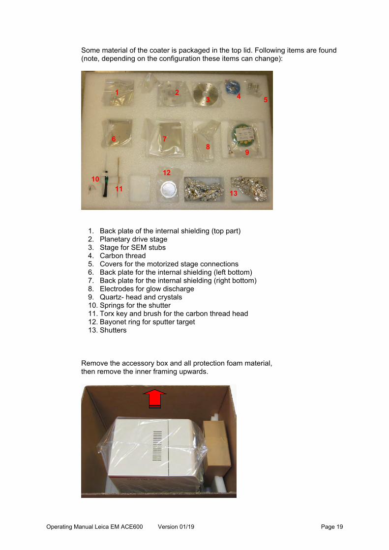
Some material of the coater is packaged in the top lid. Following items are found (note, depending on the configuration these items can change):
1. Back plate of the internal shielding (top part) 2. Planetary drive stage 3. Stage for SEM stubs 4. Carbon thread 5. Covers for the motorized stage connections 6. Back plate for the internal shielding (left bottom) 7. Back plate for the internal shielding (right bottom) 8. Electrodes for glow discharge 9. Quartz- head and crystals 10. Springs for the shutter 11. Torx key and brush for the carbon thread head 12. Bayonet ring for sputter target 13. Shutters
Remove the accessory box and all protection foam material, then remove the inner framing upwards.
1 2 3 4 5
6 7 8
9
10 11
12
13

Operating Manual Leica EM ACE600 Version 01/19 Page 20
Lift out the unit by grasping underneath the back and the front as indicated in the picture (packaging provides recess for hands) and place it on a table. Two strong people are required to lift the coater!
Place the Leica EM ACE600 on a stable bench. Adjusted all feet and counter lock (flat spanner 13 mm) to maintain level and stable positioning. Connect mains cable. If venting with nitrogen gas, connect to nitrogen gas (supplied hose, 6 mm diameter). Regulate nitrogen pressure to ~0.5 bar over atmosphere.

Operating Manual Leica EM ACE600 Version 01/19 Page 21
For sputtering process only: Connect to argon gas (supplied hose, 6 mm diameter). Purge argon line before connecting to remove the air from inside the hose. This can help to reduce the pump down time. Regulate argon pressure to ~0.5 bar over atmosphere. We strongly recommend using a two-stage pressure regulator on the argon bottle.

Operating Manual Leica EM ACE600 Version 01/19 Page 22
3.6 Inserting chamber shielding
For transporting, the main shielding only is secured in the vacuum chamber. To install the back-shielding take the main shielding out of the vacuum chamber and place it on a clean surface. Start with placing the glass shielding for the chamber light in the main shielding. A pack of 100 glass shields is included in the delivery.
Take out the main shielding and unscrew the screw on the top middle of the chamber shielding which holds the part to separate and close the gap between the two shutters.

Operating Manual Leica EM ACE600 Version 01/19 Page 23
Take out the metal holder.
Put in a glass shield. (or take out the coated round glass and replace it with a new one).
Put the metal bar back to its spot and screw it on gently.

Operating Manual Leica EM ACE600 Version 01/19 Page 24
Take the back plate of the shielding out of the packaging (3 flat sheets).
The three plates fit together in the rear of the coater like as shown here:
The first shield goes into the right top corner of the rear of the coating chamber. Align hole to the pin on the chamber wall and push on.
1 2
3
1

Operating Manual Leica EM ACE600 Version 01/19 Page 25
The second shield fits into the top left corner of the chamber wall. The pin on the second shield holds the third shield. The third shield covers the bottom of the rear of the coating chamber.
Make sure the back plates are firmly pushed against the back wall of the coating chamber otherwise the shutter could be stuck.
2
3

Operating Manual Leica EM ACE600 Version 01/19 Page 26
3.7 Shutter installation
Remove the shutter(s) from the packaging: Shutter without the glow discharge electrode
Thumb screw (1) Shutter with a glow discharge electrode and contact (optional)
Electrode plate (2) Glow discharge connection (3) Glow discharge cable (4)
Screw the shutter into the hole (see picture on previous page) in the middle of the rear of the coating chamber by the thumbscrew. Tighten firmly.
1 2
3
4

Operating Manual Leica EM ACE600 Version 01/19 Page 27
If a glow discharge is present, lace guide the cable through the recesses on the shutter (1) and plug in the connection (2).
Slide the extra packaged shutter spring (1) on to the pin on the shutter (2). *Instrument on this picture equipped with two sources
For an instrument with two sources, repeat the same for the installation of the second shutter.
1
2
1
2

Operating Manual Leica EM ACE600 Version 01/19 Page 28
3.8. Quartz crystal measurement installation
The Leica EM ACE600 is equipped with quartz crystal film thickness measurement. The QSG equipment for installation includes: - Quartz head with cable (1) - Quartz crystals (2)
Unscrew the cover of the quartz holder.
Place a quartz crystal on the copper springs (1), the grey part facing downwards (2).
2
1
1
2
1

Operating Manual Leica EM ACE600 Version 01/19 Page 29
Replace the cover and tighten gently.
Slide quartz (1) from the top through the hole (2) in the middle of the stage.
Push the quartz head down until it firmly sits on the stage. Quartz is placed correctly on the stage.
1
2

Operating Manual Leica EM ACE600 Version 01/19 Page 30
Connect the plug of quartz measuring cable to the feed through in the rear right of the coating chamber.
When using a holder to mount the quartz on the side of the stage (see images under 3.8.1), do not forget to change the settings from quartz on stage to quartz on side as described in 4.1.
Changing the quartz crystal should be done when the quartz holder is not mounted. This is to prevent any unintentional turning of the head against the cable, which can lead to a broken cable.
3.8.1 Eccentric quartz holder
When installing the holder to place the quartz on the side of the stage, please make sure it slides into the gap all the way in.

Operating Manual Leica EM ACE600 Version 01/19 Page 31
The cover in the middle of the stage could be in the way.
Loosen the screw with an Allen key and lift up the cover slightly, the stage will slide in.
Do not forget to change the quartz settings from stage to side (see 3.1.1). Minimum required working distance is 80mm and the measurement is calibrated to 0 tilt. Note for sputter processes. When using the side settings for the quartz Argon pressure of 2x10⁻² to 9x10⁻³ mbar or lower should be used for the sputtering. Above the measurement is less accurate.

Operating Manual Leica EM ACE600 Version 01/19 Page 32
3.9. Stage installation
The coater is delivered, according to the configuration, either with a rotating stage (tilt and height are manual, rotation is automated) or motorized stage (tilt, height and rotation are automated) already installed. The stage distance from the source can be set between 30 and 100 mm, the maximal tilt is ±60°. When tilted the range for the stage distance is limited to 45 to 100 mm. The stage can hold up to 24 SEM stubs. A stage for two glass slides or a planetary drive stage is available as an option, which is easily installed by exchanging the table. Cover the connections of the motorized stage with the delivered covers.
The motor spindle is covered and secured with a screw.

Operating Manual Leica EM ACE600 Version 01/19 Page 33
The table is placed on the installed stage. Make sure the pin (1) on the stage and the hole (with O-ring) on the table (2) connect.
Motorized stage (1) with table (2) to load up to 24 standard 12.7 mm (1/2”) SEM stubs with a pin diameter of 3.2 mm.
The optional table is used for two 76 mm x 26 mm (3” x 1”) standard glass slides.
1
2
1
2

Operating Manual Leica EM ACE600 Version 01/19 Page 34
The optional planetary table (1) can hold up to 24 standard 1/2” SEM stubs (six planets (2) receiving 4 SEM stubs each).
The planetary table is placed on the stage connecting first the screw (1) with the threaded hole, then turning the table until the pin on the table connects with the hole on the stage. Then, gently tighten the small thumbscrew (1).
Table installation is the same for motorized and rotating stage. The following images illustrate the tilt and height adjustment for a rotating stage.
It is important to always have all planets placed on the planetary drive stage when coating samples. The planets cover and therefore protect the mechanics from being coated, which can lead to friction and compromised rotation.
1
2
1

Operating Manual Leica EM ACE600 Version 01/19 Page 35
3.9.1 Rotating stage
Angle adjustment (each line equals 10 degrees) Left image: The thumbscrew (1) defines how much force is needed to adjust the tilt. The screw should not be opened for adjusting. Right image: Pointer for the scale of the rotating stage to adjust the height (each line is 10 mm).
The rotating stage can be easily exchanged with a motorized stage.
1
2

Operating Manual Leica EM ACE600 Version 01/19 Page 36
Stage on the lowest position equals to a source distance of 100 mm. (1) Tilt adjustment, (2) Height adjustment.
1
2

Operating Manual Leica EM ACE600 Version 01/19 Page 37
4. Operating instructions
Touch screen control panel The LCD control panel is used for communicating with the Leica EM ACE600 coating system as well as for data input and output. The parameters for the coating process are edited via the touch screen. For operating the screen, a touch screen pen can be useful. For calibrating the screen, a touch screen pen should be used. Sharp pointers may damage the touch screen. As an example, the main screen of a highly equipped instrument is shown with sputtering (1), e-beam evaporation (2), glow discharge (3) and a cryo stage (4). In addition, there is a transfer system available (5). Single processes can be put into sequence (6). On the left-hand side of the touch screen panel there is always an overview of the pumping and vacuum status shown as well as the temperatures of the stage when available (7).
The software can be updated by the user using a USB stick. During the update the instrument must not be switched off otherwise, the system may not function.
1 2 3
4 5
7
6

Operating Manual Leica EM ACE600 Version 01/19 Page 38
4.1 General functions
Push menu on the first screen after switching on the instrument to access files (1), check the quartz crystal (2) and adjust system settings (3).
Main (4) always brings you back to the first screen with the overview of available processes. Update (5) is used when a software update is performed. The light button (6) operates the chamber light and the Service button (7) gives access to the service environment asking for a password. This area is reserved for Leica authorized personnel. Log files can be downloaded or deleted and protocols can be uploaded. Connect a USB stick to the port on the touch screen panel and select
Shows all the log files. They can be selected by tapping on them and exported to a USB stick.
1 2 3
4 5 7 6

Operating Manual Leica EM ACE600 Version 01/19 Page 39
All stored processes can be exported onto a USB stick and be imported back to the instrument from a USB stick.

Operating Manual Leica EM ACE600 Version 01/19 Page 40
Gives the option to download following files and information form the coater:
Gives the option to create new materials for the different coating processes. Example sputter materials: Add a new material and fill in the required data (specific weight and settings for pre-sputtering). Tap on a line for copying or editing the material. The pre-set materials are locked, only new ones can be edited.
Example carbon thread material settings. Add a new material and fill in the required data (specific weight of carbon and the parameters for pulsing or flashing method). Tap on a line for copying or editing the material. The pre-set material is locked, only new ones can be edited.

Operating Manual Leica EM ACE600 Version 01/19 Page 41
The instrument can test the frequency of the quartz.
A new quartz has a frequency of 6 MHz and can be used until it shows unstable in the quartz test. E.g.: 1 nm carbon is reflected in about 15 Hz reduction, 1 nm of platinum refers to around 145 Hz.
If a side quartz is used it has to be set accordingly on this screen, otherwise the thickness calculation is wrong.

Operating Manual Leica EM ACE600 Version 01/19 Page 42
Under System, parameters, such as units, time, and volume of the instrument can be adjusted. Using the Export button, all relevant instrument information can be saved into a USB Stick. Additionaly, the stage can be set to its initial position.
The coater is delivered calibrated. If the touch seems to lose its accuracy, calibrate the screen.
4.1.2 Software update
Enter the menu, connect a USB stick to the port on the touch screen panel and press update.
Choose from the list which updates shall be performed by pushing the respective button on the select update column.

Operating Manual Leica EM ACE600 Version 01/19 Page 43
It is required to first update the user interface and then the required controllers.
The update files need to be on a USB-stick in a folder with the directory Leica/CTupdate.

Operating Manual Leica EM ACE600 Version 01/19 Page 44
4.2 Pump and Vent
The system can be pumped down at any time. It can be vented at any time when a process is not running. In addition, there is the option to set the turbo pump into the standby mode. This is recommended when the instrument is kept running for a longer period to keep good vacuum. The pressure bar indicates the pumping and venting progress. If the door is not closed, the pumping cycle will not start and an error message will appear. A time-out message shows if there is a leak when pumping down (e.g. the source is not placed correctly, or the chamber door is not closed). Time can be saved by starting the pump as soon as the sample is placed in the chamber otherwise pumping will start only when a process run is started. Also the sputter process can be speed up when the turbo pump is already in standby (faster adjusting of the sputter vacuum). The vacuum level is visualised using the vacuum bar.
On most screens there is a vacuum bar element included to quickly read the vacuum level.

Operating Manual Leica EM ACE600 Version 01/19 Page 45
4.3 Vacuum test
After connecting the coater as described in 3.5, the coater can be tested for vacuum. Switch on the instrument on the rear by pushing the mains switch down and push the Pump button.
If the vacuum does not reach 100 mbar in 5 min, a vacuum leak is present and needs to be eliminated.
4.4 Process start and stop
The coating process can be started at any time (system evacuated or not) if the door and source cover are closed and the source is connected (electronic safety switches prohibit starting with open door or source cover).
The button will turn into a button when the system starts the coating cycle. Once the “Start” button is activated, the coater will automatically run the complete coating cycle. At the end of the process the system eithers stays under vacuum or vents automatically (vent after process is activated, defined within the process parameters). Pressing the “Stop” button will terminate the process (after confirmation) regardless of the step of the process. The system either stays under vacuum or vents automatically (vent after process is activated, defined within the process parameters)
4.5 Thickness monitoring and geometrical correction (QSG)
A quartz crystal swings in a certain frequency. Coated with a material, this frequency reduces according to the material and the applied thickness. With this information, the accurate film thickness coated during a process run can be determined. Every Leica EM ACE600 system is equipped with the QSG film thickness measurement monitor. The user can choose between termination by QSG and
Operating Manual Leica EM ACE600 Version 01/19 Page 46
termination by timer. Even when terminating by timer, if the quartz is installed the layer thickness is displayed in the summary of a finished process. The quartz crystal is positioned in the middle of the table of the stage. The tooling factor to correct a height difference of the sample surface of a large sample to the quartz is calculated automatically. According to the selected metal or carbon thread, the parameters set are used to calculate the layer thickness.
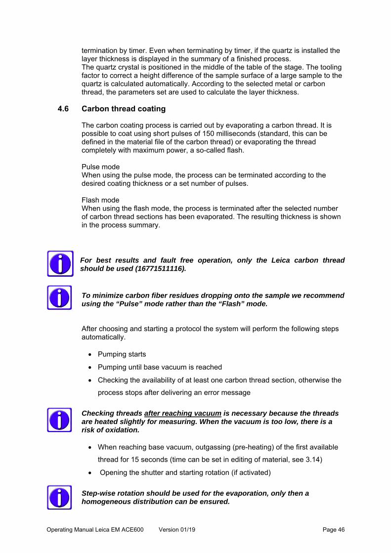
4.6 Carbon thread coating
The carbon coating process is carried out by evaporating a carbon thread. It is possible to coat using short pulses of 150 milliseconds (standard, this can be defined in the material file of the carbon thread) or evaporating the thread completely with maximum power, a so-called flash. Pulse mode When using the pulse mode, the process can be terminated according to the desired coating thickness or a set number of pulses. Flash mode When using the flash mode, the process is terminated after the selected number of carbon thread sections has been evaporated. The resulting thickness is shown in the process summary.
For best results and fault free operation, only the Leica carbon thread should be used (16771511116).
To minimize carbon fiber residues dropping onto the sample we recommend using the “Pulse” mode rather than the “Flash” mode. After choosing and starting a protocol the system will perform the following steps automatically. Pumping starts
Pumping until base vacuum is reached
Checking the availability of at least one carbon thread section, otherwise the
process stops after delivering an error message
Checking threads after reaching vacuum is necessary because the threads are heated slightly for measuring. When the vacuum is too low, there is a risk of oxidation. When reaching base vacuum, outgassing (pre-heating) of the first available
thread for 15 seconds (time can be set in editing of material, see 3.14)
Opening the shutter and starting rotation (if activated)
Step-wise rotation should be used for the evaporation, only then a homogeneous distribution can be ensured.

Operating Manual Leica EM ACE600 Version 01/19 Page 47
Pulsing to the desired thickness or pulsing/flashing the requested number of
pulses/sections. Each section required to fulfil the set protocol is outgassed
separately before use.
Closing the shutter
Displaying the results of the process (thickness, number of pulses / flashes)
Venting or staying in vacuum
4.6.1 Loading a carbon thread
The carbon thread can be loaded as a single thread or as a double thread. Thin layers from 1 to at least 20 nm can be achieved (there is variance in threads). To minimize carbon thread waste, when loading a double thread, cut a piece of thread twice as long as the width of the black door frames of the coater. Fold the thread into half and load it. Make sure the instrument is vented (see 3.2). Open the source cover (1)
Unplug the connectors (2)
Unscrew the 2 evaporation head screws to remove the flange (3)
Prepare the following parts on a clean desk:
1
2
3

Operating Manual Leica EM ACE600 Version 01/19 Page 48
Carbon head (1)
Torx TX 10 (2)
Brush (3)
Carbon thread (4)
Loosen all 5 clamp screws with the Torx key.
Remove any carbon thread residue using the brush supplied.
Do not brush off the threads close to the instrument. Use a bin well a side and placed on the floor. This avoids fibers to reach the inside of the instrument.
1 2
3 4

Operating Manual Leica EM ACE600 Version 01/19 Page 49
Loop the carbon thread around the first clamp and pull both ends gently to the left. At the same time tighten the screw as shown in the picture.
Wind the thread around the other clamps. Take care that the thread slides into the clamping groove (1), follow the path:
Pull the thread gently and tighten the last clamp.
Tighten the remaining 3 screws and trim thread on both ends.
1

Operating Manual Leica EM ACE600 Version 01/19 Page 50
If not all screws are tightened the instrument may not recognize the thread section. Clean the sealing surface with a lint-free tissue.
There is a Leica EM ACE600 YouTube video where the loading of the thread can be seen: http://www.youtube.com/watch?v=Qj3Y-WfNbvM After the carbon thread is loaded, replace the head, gently tighten the fastening screws and connect the cables and close the cover. Do not tighten the screws when the instrument is under vacuum. They can’t be opened when vented and there is a risk of damaging the thread.

Operating Manual Leica EM ACE600 Version 01/19 Page 51
4.6.2 Choosing a carbon thread protocol
When the head is inserted after completing the preparation in 4.6.1 an evaporation process can be run. Select carbon thread on the first screen to enter the process screen. In the library of recipes (1) all stored protocols are available and can be chosen. Tapping on the characteristics of the protocol (2), opens the list of recipes. There, the parameters for the process can be changed and saved. Thickness or pulses/flashes can be adjusted on the process screen (3). Once everything relevant for the coating process is defined, the process can be started (4).
Select a protocol by tapping on it. Once it is marked, by tapping on a specific category, the parameters can be changed. Alternatively, a protocol can be copied and then modified or a new one added.
1
2
3
4

Operating Manual Leica EM ACE600 Version 01/19 Page 52
When a sample is especially heat sensitive there is the material “carbon thread low power” available. The evaporation temperature is lower but with increased pulse duration. The method defines if the thread is pulsed or flashed (1). By ticking or un-ticking the quartz usage box (2), it is defined how many pulses (or flashes) are done (3) or if the process is finished by a thickness threshold (4). In case the thread was mounted doubled to reach higher thickness, the double thread box must be ticked (5).
Defining the sample height ensures that the working distance is kept constant. The carbon thread source is angled 25° towards the stage. Tilting the stage influences the coating angle. Rotation can be either set to continuous or a 120° turn after each pulse (1). Settings can be checked by pushing the Test button. Init stops the testing and moves the stage to the init position.
1
2
3
4 5

Operating Manual Leica EM ACE600 Version 01/19 Page 53
4.6.3 Carbon thread materials
New carbon thread materials can be defined to adjust the pulsing or flashing characteristics. Open Menu, tab file and material management. Select an existing material or add a new one. Set the parameters for the degassing process (heat current, heat voltage and heat time). Pulse power is the value the instrument tries to reach (adjusting current and voltage accordingly). Time between the pulses and duration of a pulse is defined.
Flash current and voltage are a limit. The flash voltage can be adjusted to desired value.
1

Operating Manual Leica EM ACE600 Version 01/19 Page 54
Each thread is degassed separately before it is used. The system waits after outgassing to stabilize the vacuum.
4.7 Sputter coating
Magnetron sputter coating is performed using ionized argon to create a plasma. The argon-ions are accelerated by high voltage and directed towards the source via a magnet where they collide with the target and displace surface atoms. Due to this collision, the surface atoms are directed towards the area below the target and coat the sample. This coating process can be more directional (sputtering at better vacuum low 10-3 mbar) or diffuse (more even coating on a bigger surface and fissured samples, sputtering at low 10-2 mbar). This also influences the coating rate (diffuse means slower rate) and the grain size (directional means finer grains). With the quartz thickness measurement (QSG) the layer thickness can be calculated because of the changed quartz crystal resonance frequency (3.8). Targets
Various targets can be supplied by Leica Microsystems for the EM ACE600 for example: Gold Gold-Palladium Platinum Platinum-Palladium Silver Chromium Tungsten Iridium Copper Nickel

Operating Manual Leica EM ACE600 Version 01/19 Page 55
Argon gas supply
The working gas (argon) must be supplied under a pressure of ~500 mbar (+/- 100 mbar) maximum. The gas may be supplied via a fixed line or from a gas bottle. The gas should be at least 99.99 % pure. After choosing and starting a protocol, the system will perform the following steps automatically. Pumping until purge vacuum (1x10⁻⁴ mbar) is reached When reaching the purge vacuum the set number of purge cycles is executed Pumping until base vacuum is reached Turbo pump reduces pumping speed to stand by Letting in argon to reach working vacuum Stabilizing plasma Pre-sputtering, if target requires (to clean the target from oxidation and enable
a stable sputter rate) Starting the sputtering process by opening the shutter and starting rotation (if
set to rotate)
Unclean targets can cause plasma instability and therefore abort the process. Only using Leica targets can insure problem-free sputtering.
Rotation should be used for the evaporation, only then a homogeneous distribution can be ensured. Termination of sputtering by either time or thickness Closing the shutter Displaying the results of the process (thickness and time) Venting or staying in vacuum
4.7.1 Loading the sputter target
Make sure the instrument is vented and open the source cover (1). Unplug the connector (2). Unscrew the two sputter head screws to remove the flange (3).

Operating Manual Leica EM ACE600 Version 01/19 Page 56
Remove the bayonet ring by turning and insert the sputter target.
Fix target by gently tightening the bayonet ring.
Tighten the ring by hand only. There is a Leica EM ACE600 YouTube video which also shows the loading of the target http://www.youtube.com/watch?v=Qj3Y-WfNbvM When the target is secured, replace the sputter head, gently tighten the fastening screws and connect the cable and close the cover.
2
3
1

Operating Manual Leica EM ACE600 Version 01/19 Page 57
Do not tighten the screws when the instrument is under vacuum. They can’t be opened when vented and there is a risk of damaging the thread.
4.7.2 Choosing a sputtering protocol
When the head is inserted after completing the preparation in 4.7.1 a sputtering process can be run. Select a sputter process on the first screen to enter the process screen. In the library of recipes (1) all stored protocols are available and can be chosen. Tapping on the characteristics of the protocol (2) opens the list of recipes. There, the parameters for the process can be changed and saved. Only thickness can be adjusted on the process screen (3). Once everything relevant for the coating process is defined, the process can be started (4).
Select a protocol by tapping on it. Once it is marked, by tapping on a specific category, the parameters can be changed. Alternatively, a protocol can be copied and then modified or a new one added.
1
2
3
4
Operating Manual Leica EM ACE600 Version 01/19 Page 58
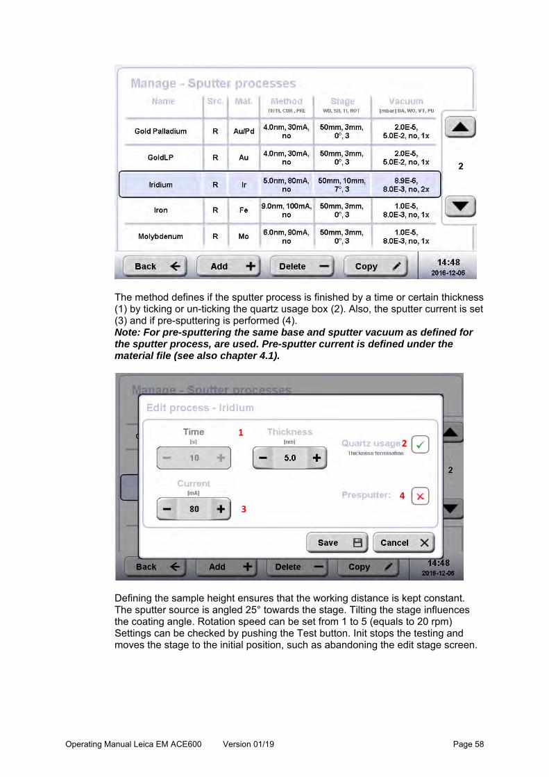
The method defines if the sputter process is finished by a time or certain thickness (1) by ticking or un-ticking the quartz usage box (2). Also, the sputter current is set (3) and if pre-sputtering is performed (4). Note: For pre-sputtering the same base and sputter vacuum as defined for the sputter process, are used. Pre-sputter current is defined under the material file (see also chapter 4.1).
Defining the sample height ensures that the working distance is kept constant. The sputter source is angled 25° towards the stage. Tilting the stage influences the coating angle. Rotation speed can be set from 1 to 5 (equals to 20 rpm) Settings can be checked by pushing the Test button. Init stops the testing and moves the stage to the initial position, such as abandoning the edit stage screen.
1 2
3
4

Operating Manual Leica EM ACE600 Version 01/19 Page 59
Two kinds of vacuum have to be defined. The vacuum which needs to be reached before the sputter process starts (=base vacuum) and the sputter vacuum which will be adjusted by letting argon gas in. Purging flushes argon gas through the tubes into the chamber to clean out other molecules.
If the focus is on fast coating rather than finest layers, a low base vacuum can be set and the turbo pump run in standby. The sputter vacuum will be reached much faster in this way.
Purge cycles: Argon is let in for 10 seconds and then pumped for 30 seconds. Sputter material:

Operating Manual Leica EM ACE600 Version 01/19 Page 60
Density is the specific weight (g/m3) of the material. Set if pre-sputtering is required. Set the pre-sputtering current and time.
4.7.3 Parameters for sputter coating
MaterialCurrent
in mA
Presput
tering
in s *
Thic
knes
s nm
Time
Sputter
Vaccum
mbar
WD
mm
Rotation
(1‐5)Tilt
Purge
Vacuum
Base
Vacuum
**
Expected
rate app.
***
Au 30 ‐ 4 50 5x10‐2 50 3 no 8x10‐5 8x10‐6 0,1 nm/s
Au/Pd 30 ‐ 4 50 5x10‐2 50 3 no 8x10‐5 8x10‐6 0,07 nm/s
Pt 35 ‐ 4 50 5x10‐2 50 3 no 8x10‐5 8x10‐6 0,07 nm/s
Pt/Pd 35 ‐ 4 50 5x10‐2 50 3 no 8x10‐5 8x10‐6 0,07 nm/s
Ag 35 30 4 50 4x10‐2 50 3 no 8x10‐5 8x10‐6 0,1 nm/s
Cr 110 120 4 10 8x10‐3 50 3 no 2x10‐5 3x10‐6 0,44 nm/s
W 90 60 4 10 8x10‐3 50 3 no 2x10‐5 3x10‐6 0,4 nm/s
Ir 80 ‐ 3 10 8x10‐3 50 3 no 2x10‐5 3x10‐6 0,1 nm/s
Al 100 60 9 60 1x10‐2 50 3 no 5x10‐5 5x10‐6 0,15 nm/s
Ti 100 60 4 50 1x10‐3 50 3 no 5x10‐5 5x10‐6 0,12 nm/s
Md 90 60 6 15 8x10‐3 50 3 no 5x10‐5 5x10‐6 0,4 nm/s
Ni 100 60 10 40 2x10‐2 50 3 no 5x10‐5 5x10‐6 0,25 nm/s
Cu 60 30 10 50 2x10‐2 50 3 no 5x10‐5 5x10‐6 0,2 nm/s
Co 100 60 4 50 2x10‐2 50 3 no 5x10‐5 5x10‐6 0.08 nm/s
* all sputter currents 10% higher than the sputter current (to remove the oxid layer)
** To safe time, the base vacuum can be reduced to the 10‐5 range
*** This rate is only a very rough estimation
Parameter sugestions for ACE600
In case the vacuum or plasma cannot be stabilized, check if the argon line is open.
4.7.4 Sputter materials
New sputter materials can be defined. Open Menu, tab file and material management. Select an existing material or add a new one.

Operating Manual Leica EM ACE600 Version 01/19 Page 61
Define the density of the new material and the pre-sputter time and current under Method.
4.8 E-beam coating
E-beam coating is the type of coating which gives the finest grains. Additionally, the coating is directional. Different materials (carbon and metals) can be evaporated. Typically, carbon or carbon/platinum layers are produced by e-beam evaporation. Those will be described in this chapter. The carbon rod has a diameter of 3 mm. The carbon rod with a drilled recess holds a platinum inlet of 2 mm. The platinum inlet is either glued into the recess with conductive carbon cement or slightly deformed so it does not fall out of the rod. To melt the inlet in, the rod is mounted in the same way as for evaporation (see protocol below) and heated up with the degassing process.
For low angle rotary shadowing applications two extra stages, including a holder to mount the quartz on the side of the stage, are available. One standard and one to clamp grids.
When using a LARS or grid stage for low angle rotary shadowing with the quartz mounted on a holder on the side of the stage, do not forget to change the settings from quartz on stage to quartz on side as described in 4.1.

Operating Manual Leica EM ACE600 Version 01/19 Page 62
Grid stage and standard stage with a diameter of 60 mm:
Standard stage and quartz holder mounted on the EM ACE600
After choosing and starting a protocol for e-beam evaporation the system will perform the following steps automatically (see 3.9.2 and 3.9.3). Pumping
Pumping until base vacuum is reached
Setting the stage
Degassing the target material (if activated)
Opening the shutter and starting rotation (if activated)
Evaporating until final thickness is reached or defined time has elapsed
Closing the shutter
Displaying the results of the process, venting or staying in vacuum
Caution!
Be careful when reloading a just used e-beam source. The inside of the source can get extremely hot.

Operating Manual Leica EM ACE600 Version 01/19 Page 63
4.8.1 Loading an e-beam evaporation source
There are two collets delivered with the e-beam source, one for the 3 mm carbon rod (1) and one for the 2 mm carbon rod for a platinum inlet (2).
Make sure the instrument is vented. Open the source cover (1)
Unplug the connectors (2)
Unscrew the 2 evaporation head screws to remove the flange (3)
Prepare the following parts on a clean desk:
1
2
3
1 2

Operating Manual Leica EM ACE600 Version 01/19 Page 64
1. Special tool to unscrew the holding ring
2. Special tool to take out the aperture for adjusting or cleaning
3. Special tool to lift out the e-beam source
4. Special tool to push out the carbon rod from the collet
5. Alignment tool for the tungsten filament
6. Wrench size 5 for exchanging for the collet
7. Allen key size 2 for opening the Wehnelt cylinder
8. Allen key size 3 for exchanging the tungsten filament
1. Carbon rods 2. Tungsten filaments 3. Carbon rods for platinum 4. Platinum inlets
Place the e-beam source on a clean table.
1
2
3
4 5
6 7 8
12
3
4

Operating Manual Leica EM ACE600 Version 01/19 Page 65
Use the special tool to unscrew the holding ring.
Remove the holding ring and place the holding ring next to the e-beam source.
Holding ring
e-beam source

Operating Manual Leica EM ACE600 Version 01/19 Page 66
Use the special tool to take out the e-beam source, by screwing it into the thread in the middle.
Pull upwards to get the e-beam source out of the housing.
When the source is hot, separate the rod and the e-beam source after taking it out. Due to the heat expansion, it could be permanently stuck together.
For easy further operation, the e-beam source can be placed into the holding ring. Open the screw to access the filament and target. The filament can be seen through this window.

Operating Manual Leica EM ACE600 Version 01/19 Page 67
Do not forget to open the window otherwise the Wehnelt cylinder is stuck on the tungsten filament.
The placement of the target can be seen (when adjusted) through the window. The tip of the carbon rod should be in the middle of the coil. Same for the platinum tip.
To adjust the rod, turn the collet holder on the bottom of the e-beam source.

Operating Manual Leica EM ACE600 Version 01/19 Page 68
To clean the e-beam source without taking it completely apart, compressed air (oil and water free!) can be used to blow through the hole.
Thorough cleaning with scotch brite, sandblasting or similar is recommended every time the filament is changed. Filaments are not changed preventively; their lifetime varies a lot. They are changed when they cannot stabilize the evaporation anymore.

Operating Manual Leica EM ACE600 Version 01/19 Page 69
To change the filament, the Wehnelt cylinder has to be removed by opening the two screws on the top. Take out the screws and lift up the Wehnelt cylinder.
Carbon rod (1) inside the tungsten filament (2) can be seen.

Operating Manual Leica EM ACE600 Version 01/19 Page 70
To change the carbon rod, screw out the collet holder.
If the carbon rod is stuck in the collet, there is a pin available to push it out from the back side.
1
2

Operating Manual Leica EM ACE600 Version 01/19 Page 71
To prepare a carbon rod take a new rod and cut it in half. Use a razor blade to score the middle. After scoring the surface…
….it can be broken in half.

Operating Manual Leica EM ACE600 Version 01/19 Page 72
To prepare a carbon platinum rod, take a new 2 mm carbon rod with recess and a platinum inlet.
Method 1: Take some pliers and bend the round platinum into a slightly oval shape.
Then put the inlet into the carbon rod. If bent enough the inlet stays in the rod.

Operating Manual Leica EM ACE600 Version 01/19 Page 73
Method 2: Take some fibers of a carbon thread and place them on the platinum pellet.
Push the carbon rod on the pellet.
Some fibers will stick out.

Operating Manual Leica EM ACE600 Version 01/19 Page 74
Rubbing with a lint-free paper over the surface will remove all the fibers. The platinum pellet is now fixed into the rod and ready for melting in.
Method 3: Glue the pellet with some carbon cement into the carbon rod. A tooth pick or similar and forceps are needed.
Apply some carbon cement…

Operating Manual Leica EM ACE600 Version 01/19 Page 75
Make sure to work fast, the cement dries very quickly.
… and put the platinum pellet in.
Clean the squeezed out cement with a tissue.
The platinum carbon rod is prepared for melting in (degassing, image shows a melted in rod).
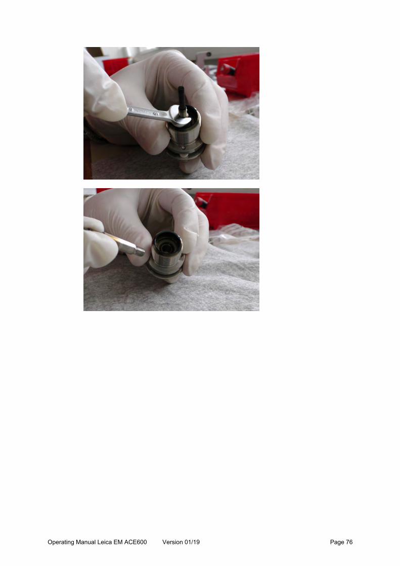
When changing from carbon evaporation to platinum or the other way round, the collet is screwed out of the collet holder. Usually this can be done by hand. In case it is too tight, the wrench number 5 is used.
Operating Manual Leica EM ACE600 Version 01/19 Page 76

Operating Manual Leica EM ACE600 Version 01/19 Page 77
Take the prepared rod and push it into the collet.
Fix the rod with the collet ring.
To exchange the tungsten filament loosen the two screws clamping the filament down.

Operating Manual Leica EM ACE600 Version 01/19 Page 78
Remove the old filament and slide in a new one. Place the centering rod and tighten the clamping screws. Try to avoid tension in the filament.
When the tungsten coil is fixed, take out the centering rod. Screw in the collet holder with the carbon rod. Tungsten coil and target are loaded. Make sure the spacers are in place before mounting the aperture.

Operating Manual Leica EM ACE600 Version 01/19 Page 79
Put the Wehnelt cylinder on top and fix it with the two screws.
Make sure the window is closed
Screw in the rod to hold the e-beam source, align the pins of housing and e-beam source and put the e-beam source into the housing.

Operating Manual Leica EM ACE600 Version 01/19 Page 80
Push in so all the contacts are closed and screw in the holding ring.
Do not tighten the holding ring. There is a risk it will be stuck when heating up.
Replace the e-beam source on the coater, gently tighten the fastening screws and connect the cables and close the cover.
4.8.2 Choosing an e-beam protocol
When the head is inserted after completing the preparation in 3.8.1 an evaporation process can be run. Select e-beam at the first screen to enter the process screen. In the library of recipes (1) all stored protocols are available and can be chosen. Tapping on the characteristics of the protocol (2) opens the list of recipes. There, the parameters for the process can be changed and saved. Only thickness can be adjusted on the process screen (3). Once everything relevant for the coating process is defined, the process can be started (4).
1
2
3
4

Operating Manual Leica EM ACE600 Version 01/19 Page 81
Select a protocol by tapping on it. Once it is marked, by tapping on a specific category, the parameters can be changed. Alternatively, a protocol can be copied and then modified or a new one added.
The method defines if the e-beam process is finished by a time or certain thickness (1) by ticking or un-ticking the quartz usage box (2). Ticking the degas box (3) has the effect that the target material is heated up for cleaning before evaporation is done (shutter stays closed). Degas parameters are stored in the material file. The target power will influence the coating rate (4).
Stage allows setting a coating angle or tilt of the stage. When setting a coating angle, the tilt is automatically calculated or vice versa. The working distance is kept constant. Continuous rotation from 1-5 can be set (5 equals to 20 rpm).
1 2
3
4

Operating Manual Leica EM ACE600 Version 01/19 Page 82
Note: Source distance is the real distance from sample to the evaporated material. Working distance is the vertical line form the horizontal table to the Wehnelt cylinder.
4.8.3 Parameter suggestion e-beam coating
Carbon Density: 2.25 g/cm3 Quartz: 15 Hz/nm Degassing: 75W (1,5kV / 50mA) / 5min Evaporation: 150W (1,8kV / 80mA) / Platinum Carbon Density: 19.45 g/cm3 Quartz: 130 Hz/nm Outgassing (melting in): 50W (1,0kV / 50mA) / 2min Evaporation: 100W (1,6kV / 60mA) /
Carbon should be operated between 90-150 W, Platinum between 60-100 W.

Operating Manual Leica EM ACE600 Version 01/19 Page 83
4.8.4 E-beam material
New e-beam materials can be defined. Open Menu, tab file and material management. Select an existing material or add a new one.
Density is the specific weight (g/m3) of the material.
Set if degassing power and time.
Operating Manual Leica EM ACE600 Version 01/19 Page 84
4.9. Carbon rod coating
Two 3 mm carbon rods, one with a sharpened end, are pushed against each other and a current is applied. Fine-grained carbon is evaporated. Compared to carbon thread evaporation thicker layers can be achieved and in less time. Because of the continuous evaporation a continuous rotation can be performed during the process.
Carbon rod evaporation should always be performed with quartz measurement to enable a reproducible result.
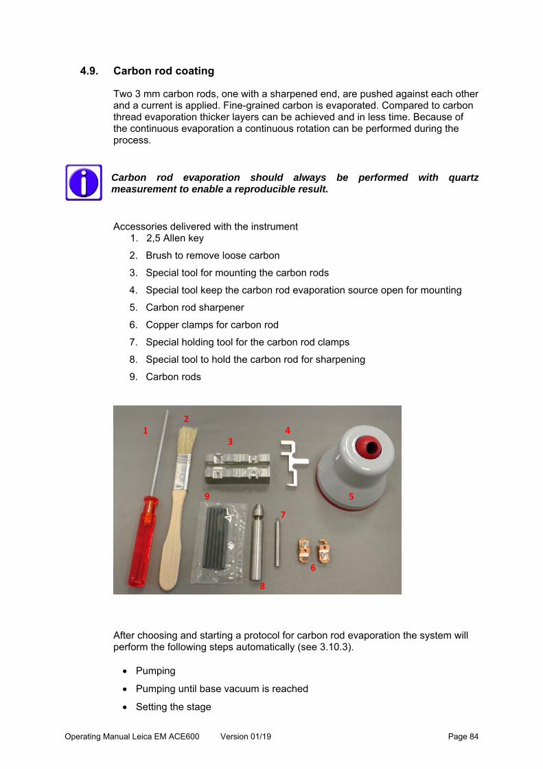
Accessories delivered with the instrument
1. 2,5 Allen key
2. Brush to remove loose carbon
3. Special tool for mounting the carbon rods
4. Special tool keep the carbon rod evaporation source open for mounting
5. Carbon rod sharpener
6. Copper clamps for carbon rod
7. Special holding tool for the carbon rod clamps
8. Special tool to hold the carbon rod for sharpening
9. Carbon rods
After choosing and starting a protocol for carbon rod evaporation the system will perform the following steps automatically (see 3.10.3). Pumping
Pumping until base vacuum is reached
Setting the stage
1 2
3 4
5
6
7
8
9

Operating Manual Leica EM ACE600 Version 01/19 Page 85
Degassing the carbon rod for set time
Opening the shutter and starting rotation (if activated)
Evaporating until final thickness is reached or defined time has elapsed
Closing the shutter
Displaying the results of the process, venting or staying in vacuum
4.9.1 Loading a carbon rod
Make sure the instrument is vented (see 4.2) Open the source cover
Unscrew the two evaporation head screws (1) to remove the cover (2)
The evaporation head (3) stays mounted in the instrument, it is only removed
for extended cleaning
Note: Make sure the copper band is not in contact with any other part.
In case, it can be easily adjusted by hand.
For regular cleaning, loose particles are removed with the brush
Prepare the following parts on a clean desk:
1
2
3

Operating Manual Leica EM ACE600 Version 01/19 Page 86
1. Special tool to keep the carbon rod evaporation source open for mounting
2. Carbon rods
3. Special tool for mounting the carbon rods
4. Copper clamps for carbon rod
5. 2,5 Allen key
6. Carbon rod sharpener
7. Special tool to hold the carbon rod for sharpening
8. Special holding tool for the carbon rod clamps
To prepare a carbon rod, take a new rod and cut it in half (approximately). Use a razor blade to score the middle. After scratching the surface …
1 2
3 4
5
7
8 6
4
Operating Manual Leica EM ACE600 Version 01/19 Page 87
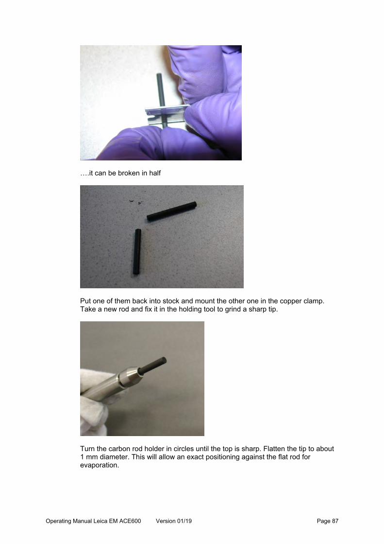
….it can be broken in half
Put one of them back into stock and mount the other one in the copper clamp. Take a new rod and fix it in the holding tool to grind a sharp tip.
Turn the carbon rod holder in circles until the top is sharp. Flatten the tip to about 1 mm diameter. This will allow an exact positioning against the flat rod for evaporation.

Operating Manual Leica EM ACE600 Version 01/19 Page 88
Take the alignment tool (1) and put in the first copper clamp (2). As shown on the image, a rod, which cannot be used for the sharp tip anymore, can still be used on the flat side.
On the shorter side (1) mount the flat rod, aligned with the edge of the recess. On the longer side (2) mount the pointy rod, the tip aligned with the edge.
1
2

Operating Manual Leica EM ACE600 Version 01/19 Page 89
Firmly tighten the screws, but do not overtighten.
If the screws to clamp the rods are not tightened enough the rod can slip through, the connection between tip and flat part will not be under spring force and evaporation is not possible.
When taking out a rod to exchange and/or sharpen it, open the screw (1) and push down. The clamp will open and the rod can be easily taken out.
Use the special tool to keep the carbon rod evaporation source (spring loaded) open.
1
2
1

Operating Manual Leica EM ACE600 Version 01/19 Page 90
With the help of the holding pin (1) which is screwed into the clamps, the carbon rod can be easily loaded in the evaporation source. Make sure the clamp (2) sits straight in the recess and firmly tighten the screw. It is recommended to start with the flat rod on the front side in respect to the instrument.
When the second rod is mounted in the same way the tool, which keeps the evaporation source, open is removed (1). The two rods should push against each other (2).
1
2
1
2

Operating Manual Leica EM ACE600 Version 01/19 Page 91
Wipe around the sealing surface with a lint free tissue and ethanol
Reattach the source cover, tighten the evaporation head screws and close the cover.
4.9.2 Choosing a carbon rod protocol
When the head is inserted after completing the preparation in 4.9.1 an evaporation process can be run. Select evaporation on the first screen to enter the process screen. In the library of recipes (1) all stored protocols are available and can be chosen. Tapping on the characteristics of the protocol (2) opens the list of recipes. There the parameters for the process can be changed and saved.
2

Operating Manual Leica EM ACE600 Version 01/19 Page 92
Thickness and time can be adjusted on the process screen (3). Once everything relevant for the coating process is defined, the process can be started (4).
Select a protocol by tapping on it. Once it is marked, by tapping on a specific category, the parameters can be changed. Alternatively, a protocol can be copied and then modified or a new one added.
The method defines if the coating process is finished by a time or certain thickness (1) by ticking or un-ticking the quartz usage box (2). Using the quartz allows to set a time between 20 and 3600s. The voltage will be increased gradually until set thickness is reached. In the example below this means: reach 5nm in 60 seconds, the voltage is increase 16.67 mV (from 5.2V to max.6.2 V) until the 5nm are reached (for information regarding the minimum and maximal voltage, refer to 4.9.3). If the quartz is not used it will be evaporated for the set time with the minimum voltage (5,2V). Pre-heat (= degassing process) is performed or not (3).
1
2
4
3

Operating Manual Leica EM ACE600 Version 01/19 Page 93
It is recommended to always use the quartz measurement for carbon rod. Defining the sample height ensures that the working distance is kept constant. The carbon thread source is angled 25° towards the stage. Tilting the stage influences the coating angle. Rotation speed can be set from 1 to 5 (equals to 20 rpm). Settings can be checked by pushing the Test button. Init stops the testing and moves the stage to the init position.
A vacuum is set which needs to be reached before the coating process starts (=base vacuum)
1
2 3

Operating Manual Leica EM ACE600 Version 01/19 Page 94
4.9.3 Carbon rod materials
For carbon rod, parameters, which will influence the coating characteristic, are defined with the material file under method (1). Density is the specific weight (g/m3) of the material. Select a material by tapping on it. Once it is marked, by tapping on a specific category, the parameters can be changed. Alternatively, a material can be copied and then modified or a new one added. The default materials are locked and cannot be overwritten (2).
Screenshot for the parameters under Method.
1 2

Operating Manual Leica EM ACE600 Version 01/19 Page 95
Set a voltage and time for pre-heating the material. The instrument starts with the minimum voltage and ramps up until a suitable deposition rate is reached up to the maximum voltage. Then it controls the parameters to maintain this rate. If a suitable deposition cannot be reached up to the maximum voltage, the deposition is terminated and a message is displayed on the screen.
4.10 Glow discharge
The glow discharge is an optional process that is used mainly to make TEM grids hydrophilic. Air is used to create plasma. This process can also be used to clean the sample surface before coating. After choosing a protocol, the system will perform the following steps automatically. Pumping until process vacuum is reached Letting in air to adjust vacuum to set pressure Stabilizing vacuum and starting glow discharge with closed shutter (purple
plasma is visible) Termination of glow discharge process by the set time Displaying the results of the process Venting or staying in vacuum
4.10.1 Choosing a glow discharge protocol
Select glow discharge on the first screen to enter the process screen. In the library of recipes (1) all stored protocols are available and can be chosen. Tapping on the characteristics of the protocol (2) opens the list of recipes. There the parameters for the process can be changed and saved. Only time can be adjusted on the process screen (3). Once everything relevant for the coating process is defined, the process can be started (4).

Operating Manual Leica EM ACE600 Version 01/19 Page 96
To use the glow discharge option, ensures that the glow discharge electrode is mounted. Select a protocol by tapping on it. Once it is marked, by tapping on a specific category, the parameters can be changed. Alternatively, a protocol can be copied and then modified or a new one added.
1
2
4
3

Operating Manual Leica EM ACE600 Version 01/19 Page 97
The method defines the current for the glow discharge process and the length of it.
Defining the sample height ensures that the working distance is kept constant. The glow discharge source is angled 25° towards the stage. Rotation speed can be set from 1 to 5 (equals to 20 rpm). Settings can be checked by pushing the Test button. Init stops the testing and moves the stage to the init position.

Operating Manual Leica EM ACE600 Version 01/19 Page 98
Two kinds of vacuum have to be defined. The vacuum which needs to be reached before the glow discharge process starts (= base vacuum) and the process vacuum which will be adjusted by letting air in.
60 seconds @ 15 mA at 4E-1 mbar (1E-3 mbar Pre-Process- Vacuum) guideline for glow discharging grids to make them hydrophilic. To ensure proper functionality of the glow discharge process please make sure the electrode is cleaned regularly especially when sputtering thicker layers.
4.11. Sequence
Single processes can be combined into a sequence. Depending on the configuration of the instrument sputtering, evaporation processes and glow discharge can be automatically run one after the other. If hardwear is present, transfer processes can be included in a sequence. They can be put in any order and repeated. All protocols of the library can be combined to a sequence. Additionally, ‘waiting’ elements to pause between two processes can be placed. On the main screen press open sequence.

Operating Manual Leica EM ACE600 Version 01/19 Page 99
The sequence main screen loads. In the library of recipes (1) all stored sequences are available and can be chosen. Tapping on the characteristics of the protocol (2) opens the list of sequences. There, the sequence can be changed and saved. Once everything is defined, the processes can be started (3).
Select a protocol for a sequence by tapping on it. Once it is marked by tapping on the name or included processes, the details can be changed. Alternatively, a sequence can be copied and then modified or a new one added.
1
2
3

Operating Manual Leica EM ACE600 Version 01/19 Page 100
The total sequence can run over several screens (change by button 1).
Tapping on add, a new process can be implemented into the sequence. First the method is selected, then the specific protocol and then the position in the sequence.
1

Operating Manual Leica EM ACE600 Version 01/19 Page 101
Mark a step in the sequence to modify it.
Tapping on an already implemented process allows changing the process itself or moving the position.
2
1

Operating Manual Leica EM ACE600 Version 01/19 Page 102
4.12 Rotating stage: difference in user interface and set-up
Rotating stage is indicated in the stage editing screen (1). It is important to set the height and tilt before starting the process.
2
1
1

Operating Manual Leica EM ACE600 Version 01/19 Page 103
The tilt and height of the stage have to be set manually (see 3.9).The lift height (l) is relative to the surface of the stage.
4.13 Running a process
Once a process is started (as example here e-beam) the instrument automatically runs through all the steps, including setting the stage, stabilizing the process, coating and post processing when quartz measurement is activated.
Tapping on the process box (Carbon in this case) shows the most important parameters of that process.

Operating Manual Leica EM ACE600 Version 01/19 Page 104
While the sample is coated the average coating rate (1) as well as the current thickness (2) and the thickness to be achieved (3) is displayed.
2 1
3

Operating Manual Leica EM ACE600 Version 01/19 Page 105
Since a quartz crystal is sensitive to light and heat the instrument runs a post-processing. That means final measurement of the quartz frequency is done some seconds after process end to calculate the final thickness. After the process is successfully run, a result screen is shown. If a USB data stick is connected, the log-file can immediately be exported.
Note for finished process: The instrument monitors the layer thickness during evaporation to stop when the desired value is reached. This includes a correction for the influence of the light radiation onto the quartz crystal. However, at the end of the process the quartz reading is again taken after waiting a suitable time to avoid any influence of the radiation and is then compared to the reading before starting the deposition. The result is given at the final screen and it indicates the layer truly deposited on the sample. It may deviate slightly from the reading displayed during the deposition because the radiation influence on the quartz is fluctuating with several parameters and can, therefore, be only approximated.

Operating Manual Leica EM ACE600 Version 01/19 Page 106
4.14 Load lock
With the optional load lock, samples can be transferred into the coater without venting the instrument. The coating process is very fast because the needed base vacuum is already reached. Also, is it beneficial when using targets, which corrode. This way they do not have to get into contact with air when the coater is vented for removal of the sample. VCT holders (up to four) have to be used to transfer the sample into the coater with the load lock. Mount the VCT holder carrying the sample on the load lock manipulator tip (1).
Attach the load lock to the dock.
Loaded sample.
1

Operating Manual Leica EM ACE600 Version 01/19 Page 107
Select transfer on the first screen to enter the load lock operating panel. This screen is only accessible when the pressure is lower than 1,0E-4 mbar.
Samples have to be mounted on a VCT holder to be transferred. A table which can receives up to four VCT holders is part of the outfit. With the buttons 1 to 4 (1) the stage can be moved to that position to receive the transferred holder. Settings (2) allows adjusting the pump and purging time of the load lock as well as closing and removing the cover of the VCT dock. Push load lock (3) to attach the load lock, open the gate valve and transfer the sample.

Operating Manual Leica EM ACE600 Version 01/19 Page 108
In case the stage must be aligned to transfer the VCT holders push Adjust and align height (1), angle (2) and tilt (3). Set will save the values for the respective position.
1
2
3
1
2
3

Operating Manual Leica EM ACE600 Version 01/19 Page 109
Screen of Settings:
Gate valve is open (2) and the load lock manipulator rod is inside the vacuum chamber.
After placing all the samples (up to four), the load lock manipulator has to be pulled out. It is recommended to close the gate valve after finishing load lock manipulation. With the button Vent, the gate valve is closed.
1 2

Operating Manual Leica EM ACE600 Version 01/19 Page 110
5. Maintenance and service
The purpose of these activities is to
Maintain the optimal operating conditions of the Leica EM ACE600 Minimize downtime Provide a standard maintenance schedule Deal with malfunctions
Malfunctions during operation of the Leica EM ACE600 coating system are reported in an information window. A clear text error message provides information about the cause of the malfunction and the action required. For further questions, regarding malfunctions refer to the error list under chapter 5. Example:
Caution! Injuries or damage to the system may be caused by servicing and cleaning the system incorrectly.
5.1 General instructions for maintenance and cleaning
External elements (dust, grease, etc.) may prevent achieving the required vacuum. When working on the vacuum chamber or parts, which are in the vacuum chamber of the Leica EM ACE600, coating system it is essential to follow the principles of vacuum hygiene. Gloves must be worn when disassembling and assembling components in the vacuum area and for all adjustment work. All work must be carried out in a clean, oil/grease-free and dust-free environment.

Operating Manual Leica EM ACE600 Version 01/19 Page 111
5.1.1 Source cover
If the source cover closes too quickly, it is possible to tighten the hinges using a 3 mm Allen key. Be careful not to over tighten.
5.2 Cleaning of the Leica EM ACE600
The internal shielding, shutter including the glow discharge electrode and the anode ring should be cleaned or replaced when:
Peeling or thick coating is visible If contamination is observed during EM imaging Pumping time to reach base vacuum increases significantly
All coating sourced should be cleaned as as soon as there is:
Clearly seen a thicker film of coating on the source The risk that material could peel off Latest when material starts to peel off
Thin threads can peel off the anode ring and cause a short circuit. Recommendation
Usually, only the glass door needs to be cleaned, depending on the layer thicknesses coated and the visibility needs. The chamber shielding, especially when always using the same material, does not need to be cleaned very often.

Operating Manual Leica EM ACE600 Version 01/19 Page 112
Cleaning material
There is a Leica cleaning product available for parts used in vacuum, which is the ideal solution for cleaning: 16771511205.
If not by hand, alternatively, metal cleaning paste works well. Scotch brite should only be used on metal parts. Do not use any abrasives on the glass door because scratches can lead to small leaks. Washing the parts afterwards with soapy water and letting them dry off is an easy way to finish the cleaning. In addition, Isopropanol or Ethanol can be used for the finish. Caution! Do not use thin tissues and ethanol for removing platinum – there is a risk of the tissue catching fire. Door
Remove the door by lifting it from its hinges (see 4.2.1) Place the door on a flat soft surface with the inner surface up To remove carbon coatings, use a 70% isopropanol solution and lint-free
tissue for the rough cleaning. Then use fine metal polish paste. Finish with soap-water or isopropanol
To remove sputter coatings, start with the fine polish paste and finish with soap-water or isopropanol

Operating Manual Leica EM ACE600 Version 01/19 Page 113
Internal shielding, shutter and glow discharge electrode How to remove the chamber parts see 4.2.1
The internal shielding can be cleaned using Scotch-Brite or metal cleaning paste. Finish with soap water and then clear water or isopropanol
When cleaning the shutter, it is recommended to lubricate the fastening screw hinge with a drop of high vacuum Fomblin oil before assembly
The glow discharge electrode can be cleaned using Scotch-Brite or metal cleaning paste. Finish with soap water and then clean with water or isopropanol. It is available as a spare part.
Anode ring
The anode ring is implemented in the opening for the sputter head. It can be removed by pushing downwards when the internal shielding is removed (see 3.6).
Occasionally, it can happen that an elongated flake builds up by the sputtered material. This can cause a shirt circuit that will be indicated by a warning when starting a sputtering process. Clean the anode ring by wiping with ethanol.
Carbon thread head The ceramic plate (1) on the carbon thread head is cleaned with a brush each time exchanging the threads. This surface must not have continuous carbon layer.

Operating Manual Leica EM ACE600 Version 01/19 Page 114
This can lead to short circuits. That is why this plate is loosely mounted. Each movement creates micro cracks in the layer. The ceramic plate can be exchanged or dismounted and cleaned completely separately. Only the two screws (2) have to be removed).
E-beam ceramic If necessary, clean the ceramic (1) of the collet holder (2). Cleaning is required when no deposition rate can be achieved even though rod and filament are functional. A dark film can be seen on the ceramic. This is more likely to happen for a platinum source than a carbon source. Cleaning can be done with sandpaper or sandblasting.
Housing
All surfaces can be cleaned with a damp, lint-free cloth moistened with either aqueous cleaning agents or 50% ethanol (ethanol - water 1:1)
Do NOT use ACETONE!
2 1
1
2

Operating Manual Leica EM ACE600 Version 01/19 Page 115
The LCD control panel should be cleaned with standard commercial screen cleaner when the system is switched off
Accidental spillage of solvents (e.g. acetone, isopropanol or ethanol) must be removed immediately with a damp, lint-free cloth moistened with aqueous cleaning agents
5.2.1 Removing and cleaining the door with a metal polisher
To remove the door lift it up and take it out.
Place the door flat on a soft surface to clean. Do not use abrasive cleaning material. Scratches could cause a vacuum leak.
The complete glass can be exchanged by unscrewing both screws on the side to hold the glass. Replace the glass and tighten the screws again.

Operating Manual Leica EM ACE600 Version 01/19 Page 116
5.2.2 Removing shutter and internal shielding
To remove the shutter and shielding the table should be taken out. Disconnect the QSG plug. Pull out the shutter spring. If present, unplug the glow discharge electrode and loosen the cable. Unscrew the shutter and take it out. This process is clearly described under 3.6 and 3.7. For removing, the process only needs to be reversed.
5.2.3 Exchanging the glass shielding for the chamber light
To exchange the glass shielding for the chamber light please refer to 3.6. Before first use, please install a glass shielding. When the chamber light becomes too dark, the shieling for the light can be easily exchanged.

Operating Manual Leica EM ACE600 Version 01/19 Page 117
6. Troubleshooting
Leica EM ACE600 – Hint/Error/Warning List
Code Title Message (Text) Description
System (Panel) Specific:
E0000 Error System halted due to an unexpected error, Restart system
Software crash (exception handling) > Restart software immediately.
E0001 Error Controller comm. Error, Restart system
No controller communication established. Check status LED and software version. Try restart or update.
E0002 Error Pump comm. Error, Restart system
No turbo-pump communication established. Check cable or H485 controller on HiVac PCB.
W0003 Warning Cannot load configuration file Configuration (cfg.ini) not loaded correctly. Auto-repair in software when restarting.
W0004 Warning Specific image is missing Specific image could not be loaded. Maybe UI update-process went wrong.
W0005 Warning Cannot load method related file
Unable to load method related file > Processes and sequences not detected.
W0006 Warning Service interval diaphragm pump exceeded, Service diaphragm pump
Diaphragm pump service interval exceeded. Reset interval in software after service.
W0007 Warning Service interval turbo pump exceeded, Service turbo pump
Turbo service interval exceeded. Reset interval in software after service.
W0009 Warning Turbo current consumption too high, Service diaphragm pump
Turbo current too high. Stop pumping and wait.

Operating Manual Leica EM ACE600 Version 01/19 Page 118
W0010 Warning Turbo temperature too high, Service diaphragm pump
Turbo temperature over-heat. Stop pumping and wait.
W0011 Warning Critical disk space, Back-up files before clean up?
Not enough memory left on device. Clean up device > Delete old logs, screenshots and update folders.
E0012 Error No pump calibration table found, please calibrate pump to ensure correct behaviour
No pump calibration file found. Calibrate pump in service.
E0013 Error No available coating method detected, Restart system
No available coating method controller detected. Check communication cables and HiVac controller status.
W0014 Warning Service interval gauge exceeded, Service gauge
Gauge service interval exceeded. Reset interval in software after service.
W0016 Warning Gauge pressure out of bounce, Restart system
Invalid gauge pressure value received. Check gauge connection or restart controller.
E0017 Error Sudden Vacuum Break Down; Check Valves and Device For Leaks
Vent after the Valve, then Open the FSA-Valve, Pressure Drop
E0018 Error Vacuum Timeout; Check Valves and Device For Leaks
W0019 Warning Side Stage, Working Distance Lower than 80 mm
HiVac Controller Specific:
W1300 Warning No quartz detected Quartz not detected. Warning only active in debug mode.

Operating Manual Leica EM ACE600 Version 01/19 Page 119
W1301 Warning
Quartz usage period exceeded, Change quartz to guarantee valid measurement
Quartz usage period exceeded after measured value > 6.1 MHz or < 4 MHz
E1500 Motor error
Lift motor error detected Initialization of lift motor failed. Try re-initialization and learning.
E1302 Process
Process terminated, Thickness not increasing (timeout), Check quartz and try again
No thickness increase in a specific time -> necessary for all methods to detect if film-thickness can be reached during process -> Check source or quartz and try to run process again
E1303 Process
Process terminated, Quartz unstable, Change quartz to guarantee valid measurement
Quartz unstable -> Measuring of frequency before process has to be stable to guarantee valid measurement -> Change quartz in case and try to run process again
E1600 Motor error
Shutter motor error detected Initialization of shutter motor failed. Try re-initialization and learning.
E1601 Motor error
Shutter motor not connected, Check cable and restart system
Shutter motor not detected during software init. Restart or check cable connections.
E1700 Motor error
Rotation motor error detected Initialization of rotation motor failed. Try re-initialization and learning.
E1800 Motor error
Tilt motor error detected Initialization of tilt motor failed. Try re-initialization and learning.
W1900 Pump fault
Door open, please close the door
Process / Pumping aborted - Check door sensor.
W1901 Pump fault
Cover open please close the cover
Process / Pumping aborted - Check cover sensor.
E1902 Process head (1) not connected, Connect cable
Process aborted - Specific head not connected!
E1903 Process head (2) not connected, Connect cable
Process aborted - Specific head not connected!

Operating Manual Leica EM ACE600 Version 01/19 Page 120
W1904 Process Process terminated, head (1) over-temperature
Process aborted - Head-temperature overheated! Temp. > 65°C
W1905 Process Process terminated, head (2) over-temperature
Process aborted - Head-temperature overheated! Temp. > 65°C
E1100 Error No gauge detected, Restart system
No gauge detected at start-up of software. Restart device.
Carbon Thread Controller Specific:
W4001 Warning No thread available No threads detected. Abort process only after resistance calculation.
W4002 Warning All threads exhausted
Process stopped - All threads exhausted in process, but still some pulses to proceed (or thickness not reached) > Abort process
W4003 Warning # of threads available, # of flashes not possible
Process stopped - Amount of existing threads smaller than desired number of flashes
E4011 Process Process terminated, no power detected, Check door and cover
Process aborted - Carbon Thread supply not powered. Check door and cover sensors
E4012 Process Process terminated, Main supply voltage fault, Check door and cover
Process aborted - Carbon Thread mains relay not switched on. Check door and cover sensors
E4013 Process Thread Measuring Timeout; Restart Process
E4014 Process Supply Off Response Timeout
Sputtering Controller Specific:
E2001 Process Process terminated mains supply voltage fault, check door and cover
HV-board not supplied. Check door and cover sensors
E2002 Process Process terminated, mains supply voltage out of range <85 V
Process - aborted. Mains supply voltage out of range (<85 V)! Check if right voltage is delivered by the network

Operating Manual Leica EM ACE600 Version 01/19 Page 121
E2003 Process Process terminated mains supply voltage out of range 150<>210 V
Process - aborted. Mains supply voltage out of range! (150<>210 V) Check if right voltage is delivered by the network
E2004 Process Process terminated, Mains supply voltage out of range >250 V
Process stop. Mains supply voltage out of range! (>250 V) Check if right voltage is delivered by the network
E2005 Process Process terminated, Current not reached, Check target and sputter source
Process aborted - Unable to reach sputter-current. Check if pressure is valid or wrong or no target is used.
E2007 Process Process terminated, Line voltage fluctuations
Process aborted - Line voltage fluctuations too big!
E2009 Process Process terminated, Sputter source short circuit! Check target and sputter source.
Process aborted - Short-circuit because of invalid assembly of head, ring or target. Check deposited solid material on shutter
E2010 Process
Process terminated, ignition fault, Check argon flow, Check target and sputter source
Process aborted - Unable to establish plasma ignition.
E2011 Process Process terminated, Sputter current could not be stabilized
Process aborted - Unstable plasma current. Unclean target could be the reason, clean with isopropanol and try again.
E2012 Process Process terminated, High voltage board defect, please contact service
Process aborted - High voltage board defect > Change board, since output cannot be controlled anymore
E2018 Process Operation Response Timeout The control unit cannot stabilize the voltage in the sputter head.
W2019 Warning Purge Base-Vacuum (1.0E-4 Mbar) Timeout. Process Anyway?
Begin Sputter using Standby Mode
Glow discharge specific:
E2109 Process Process terminated, Short circuit in glow-discharge, Check shutter panels
Process aborted - Short-circuit because of invalid assembly of plates. Check deposited solid material on shutter

Operating Manual Leica EM ACE600 Version 01/19 Page 122
E2110 Process Process terminated, Ignition fault, Check air valve and vacuum
Process aborted - Unable to establish plasma ignition.
E2111 Process Process terminated, Discharge current could not be stabilized
Process aborted - Unstable plasma current.
Cryo Controller Specific:
E8002 Process
Process terminated, Unable to reach desired temperature, Check N2 Dewar empty
Process aborted - Reaching reference temperature timeout
E8003 Process Dewar empty
E8004 Process Etching Temperature lower; LN2 empty?
VCT Specific:
E1401 Process
VCT Transfer Terminated: Stage Initialization Timeout!
E1402 Process
VCT Transfer Terminated Stage Position Incorrect!
E1403 Process Dock Not Closed
E1404 Process Dock Not Open
E1405 Process Shuttle Not Closed

Operating Manual Leica EM ACE600 Version 01/19 Page 123
E1406 Process Shuttle Not Open
E1407 Process
No Min. Dock Pressure In Interval (>100 mbar)!
E1408 Process
No Min. Purge Pressure In Interval (> 100 mbar)!
E1409 Process
Pump Does Not Reach Min. Pressure. Continue?
E1410 Process No Dock Connected
E1411 Process No Shuttle Connected
W1412 Process
Shuttle Already Under (Good) Vacuum (P < X mbar)
E-Beam Controller Specific
E9001 Warning E-Beam supply already switched on
Process aborted - Could not switch on power due power is still active
E9002 Warning Invalid high-voltage value, Set valid parameter and try again
Process aborted - Invalid parameter (voltage) sent
E9003 Warning Invalid current value, Set valid parameter and try again
Process aborted - Invalid parameter (current) sent

Operating Manual Leica EM ACE600 Version 01/19 Page 124
E9004 Process Process terminated, Chosen e-beam head not supported, Check head connection
Process aborted - Selected head not connected -> Check head configurations in service or cable connection to head
E9005 Process Process terminated, E-beam board defect, Please contact service
Process aborted - Board defect
E9006 Process Process terminated, No mains voltage on filament voltage supply
Process aborted - Mains supply not on. Check head supply / door / cover
E9007 Process Process terminated, No mains voltage on high-voltage supply
Process aborted - Mains supply not on. Check head supply / door / cover
E9008 Process Process terminated, Filament resistance too high, Check filament
Process aborted - Change filament -> Filament broken or short circuit inside head (clean source)
E9011 Process Process terminated, E-beam voltage / current not stabilized.
Process aborted - Voltage / current not stabilized -> Restart process or check source
E9012 Process Process terminated, Operation response timeout
Process aborted - Communication response timeout occurred -> Unable to stabilize or comm. Error -> Restart device
E9013 Process Filament Stabilization timeout; Restart Process
Evaporation Controller Specific Process
E5000 Warning Evaporation supply already switched on
Process aborted - Could not switch on power due power is still active
E5001 Process
Process terminated, Reference voltage incorrect, Set valid parameter and try again
Process aborted - Invalid parameter (voltage) sent
E5002 Process
Process terminated, Reference current incorrect, Set valid parameter and try again
Process aborted - Invalid parameter (current) sent

Operating Manual Leica EM ACE600 Version 01/19 Page 125
E5004 Process Process terminated, Internal ref. Voltage not ok, Check head connection
Process aborted - Internal head voltage not correct -> Check head connection (service / device tab)
E5005 Process Process terminated, Output voltage not ok. Restart device.
Process aborted - Output voltage not correct -> Check head connection, head supply or restart device (service / device tab)
E5007 Process Process terminated, insufficient contact in source. Check source mounting.
Process aborted - Resistance too high -> Contact insufficient -> Check source mounting / rod
E5008 Process Process terminated, short-circuit in source. Check source mounting.
Process aborted - Resistance too low -> Short circuit or change rod
E5009 Process Source Exhausted (Contact Loss)
E5010 Process Source Exhausted (Short Circuit)
E5012 Process Process terminated, operation response timeout
Process aborted - Communication response timeout occurred -> Unable to stabilize or comm. Error -> Restart device

EC Declaration of ConformityEG KonformitätserklärungDéclaration CE de Conformité
Leica Mikrosysteme GmbH · Hernalser Hauptstrasse 219 · A-1170 WienT +43 1 48899 0 · F +43 1 48899 350www.leica-microsystems.com
CONNECT WITH US!
Leica Mikrosysteme GmbHHernalser Hauptstrasse 219A-1170 Vienna/Wien/Vienne, Austria/Österreich/Autriche
Dr. Paul WurzingerEntwicklungsleiter/R&D Manager/Chef du service développment
Vienna/Wien/Vienna, 21/07/2017
following the provisions of directivegemäß den Bestimmungen der Richtlinieconformément aux dispositions de directive
(Electromagnetic compatibility) (Elektromagnetische Verträglichkeit)
2014/30EU
(Low Voltage Equipment) (Niederspannungsrichtlinie)
2014/35EU
(RoHS directive)(RoHS Richtlinie)
2011/65/EU
declares in exclusive responsibility that the producterklärt in alleiniger Verantwortung, dass das Produktdéclare sous sa responsabilité que le produit
Model/Modell/modèle Leica EM ACE600
Type/Typenbezeichnung/type EM ACE600
to which this declaration relates is in conformity with the following standards: auf das sich diese Erklärung bezieht, mit den folgenden Normen übereinstimmt: auquel se réfère cette déclaration est conforme aux normes:
EN 61010-1EN 61326-1

Leica Mikrosysteme GmbH | Vienna, Austria
T +43 1 486 8050-0 | F +43 1 486 8050-30
www.leica-microsystems.com
CONNECT WITH US!