operating manual - hrp refrigerant pump
TRANSCRIPT


Content
1. INTRODUCTION ................................................................................................................ 1
1.1 INTENDED USE ........................................................................................................... 1
1.2 SAFETY REQUIREMENTS ........................................................................................... 1
1.3 SAFETY ADVICE .......................................................................................................... 1
1.4 DISCLAIMER ................................................................................................................ 2
2. TERMS OF WARRANTY ................................................................................................... 3
3. TECHNICAL INFORMATION ............................................................................................. 4
3.1 DESCRIPTION OF TYPES ........................................................................................... 4
3.2 SCOPE OF DELIVERY ................................................................................................. 4
3.3 ORDER INFORMATION ............................................................................................... 4
3.4 CODES / CERTIFICATES / APPROVALS .................................................................... 5
4. TECHNICAL DATA ............................................................................................................ 6
4.1 GENERAL INFORMATION ........................................................................................... 6
4.2 ELECTRICAL DATA ...................................................................................................... 6
4.3 MATERIALS .................................................................................................................. 9
4.4 PRESSURE RANGE ..................................................................................................... 9
4.5 DIMENSIONS ............................................................................................................. 11
4.6 SECTIONAL VIEWS ................................................................................................... 14
4.7 DESCRIPTION OF OPERATION ................................................................................ 33
4.8 PERFORMANCE CHARACTERISTIC TABLE ............................................................ 33
5. APPLICATIONS ............................................................................................................... 35
5.1 GENERAL ................................................................................................................... 35
5.2 DETERMINATION OF THE DELIVERY HEAD ........................................................... 36
5.3 DETERMINATION OF THE REQUIRED FLOW .......................................................... 36
5.4 ADAPTATION TO PLANT REQUIREMENTS .............................................................. 37
5.5 USE OF FREQUENCY CONVERTERS ...................................................................... 38
6. INSTALLATION INSTRUCTIONS .................................................................................... 39
6.1 PUMP ARRANGEMENT ............................................................................................. 39
6.2 PUMP CONNECTION ................................................................................................. 39
6.3 DOWNLEG DESIGN ................................................................................................... 41
6.4 PUMP DISCHARGE LINE ........................................................................................... 42
6.5 PROTECTION OF THE PUMP.................................................................................... 43
6.6 ELECTRICAL INFORMATION .................................................................................... 48

7. TRANSPORT AND STORAGE ........................................................................................ 53
8. INSTALLATION AND APPLICATION .............................................................................. 54
8.1 PREPARING THE PUMP FOR INSTALLATION ......................................................... 54
8.2 MOUNTING INSTRUCTIONS ..................................................................................... 54
8.3 PRIOR TO COMMISSIONING .................................................................................... 56
8.4 COMMISSIONING PROCEDURE ............................................................................... 56
8.5 DURING NORMAL OPERATION ................................................................................ 56
8.6 PUMP STANDSTILL (STAND-BY) .............................................................................. 57
9. SERVICE AND MAINTENANCE ...................................................................................... 58
9.1 REMOVING A PUMP .................................................................................................. 58
9.2 SHIPPING OF THE PUMP .......................................................................................... 58
9.3 GENERAL ADVICE ..................................................................................................... 58
9.4 REPARING A PUMP ................................................................................................... 59
9.5 WARNINGS ................................................................................................................ 59
10. TROUBLE SHOOTING ................................................................................................ 61
TH. WITT Kältemaschinenfabrik GmbH
Lukasstrasse 32, D-52070 Aachen
Tel. +49-241-18208-0
https://www.th-witt.com, [email protected]
Status of documentation: October 2020
1
1. INTRODUCTION
Please read the entire manual careful before selecting, installing, commissioning and servicing the pump.
1.1 INTENDED USE
The WITT hermetic refrigerant pump type is designed to deliver exclusively refrigerant liquid at its boiling point.
The pump is labelled with model and design limitation for pressure and temperature.
The HRP refrigerant pump is designed with safety features, which ensures security from the escape of ammonia; in the event the stator can leaking the pump body and the complete motor housing is designed to 25 bar pressure to contain high pressure refrigerant will not escape from the pump or through the electric cable connections.
Performance data of the pump are to be found in chapter 4 Technical data.
1.2 SAFETY REQUIREMENTS
All of the following specified work must be carried out by knowledgeable personnel experienced in installation and service of refrigeration systems. All personnel must be familiar with the national legal requirements and safety regulations. All safety regulations and codes of practice concerning the use of refrigerants must be adhered to, with special attention paid to protection clothing and wearing of safety glasses.
Service and maintenance should only be carried out when the pump is stopped and the power supply disconnected.
Under no circumstances are the indicated temperature- and pressure limitations to be exceeded.
Important! The content of this manual must be adhered to. Deviation from the specified conditions will make any claim for liability or warrenty void.
1.3 SAFETY ADVICE
The pump is designed for use in industrial refrigeration systems of primary refrigerant.
Refrigerant is used to cool motor and bearings. Any gas that forms in the pump is discharged to the pressure side. The electrical power consumption of the pump is low in relation to the refrigeration capacity, due to the effect of the latent heat of the liquid being utilised.
It is very important that everybody responsible for the safe operation and maintenance of the plant reads this manual.
I you have any problems please do not hesitate to call our service department, our staff will be glad to assist you.

2
Avoid any tripping obstacle at ground levels, e.g. cable. If you cannot avoid such obstacles they should be marked with two-coloured warning tape (warning sign).
Retighten all screw connections after maintenance and repair work!
If you have to disassemble any safety devices for maintenance and repair make sure that upon completion of said work the re-assembly and proper functioning is checked!
When operating at low temperatures (< 0°C) freeze bites can occur when the surface is touched. Therefore always wear appropriate protection clothing.
1.4 DISCLAIMER
Even when using the pump for the intended purpose it cannot be entirely excluded that a dan-ger remains for the life of the user. Translations are carried out to the best of our knowledge. We are unable to accept any liability for translation errors.
We reserve the right to change descriptions, graphs or other statements.

3
2. TERMS OF WARRANTY
In order to avoid accidents and ensure optimum performance, no modifications or conversions may be carried out to the refrigerant pump without the explicit written approval by TH. WITT KÄLTEMASCHINENFABRIK GMBH.
These instructions are based on internationally standardised SI units of measurements.
All data and information on the operation and maintenance of the refrigerant pump is provided based on our extensive experience and to the best of our technical knowledge.
Our liability or warranty is excluded, if:
• information and instructions in the operating manual are ignored, • the refrigerant pump including accessories is operated incorrectly or is installed contrary to
these installation instructions • the refrigerant pump is used for applications other than that for which it was intended, • safety devices are not used or disconnected • there have been modifications made without written approval • the safety regulations are not adhered to • the refrigerant pump including its filters and required safety devices has not been main-
tained or repaired correctly with respect to frequency or competence this includes the use of approved spare parts.
Opening the pump within the warranty period will void all implied or explicit guarantees!
Always return the pump to the supplier for repair or order an exchange pump.
When exchanging any parts respective spare parts only genuine spare parts are to be used.
Statements in this manual shall also apply to any service fluids.

4
3. TECHNICAL INFORMATION
3.1 DESCRIPTION OF TYPES
Five hermetic pump types are available: HRP3232, HRP5040, HRP 5050, HRP8050 and HRP10080.
"HRP" means "Hermetic Radial Pump" The numbers give the inlet and outlet pipe connection size in DN; the first two/three digits give the size of the suction connection while the last two digits give the size of the discharge connection.
3.2 SCOPE OF DELIVERY
• Refrigerant pump complete with canned motor, suction strainer (model 0)
• The HRP 3232 also includes an EA 10 GÜ/GB (PN 40) drain valve
Optional scope of delivery
• Counterflange on suction side
• Counterflange on discharge side
• Shut-off valve on suction side (from HRP 5040)
• Through ball valve on suction side (only HRP 3232)
• Shut-off valve on discharge side with counter flange, vent valve (manometer connection) and cam for differential pressure switch. Cam not with HRP 3232
• lockable check valve on the pressure side with counter flange, vent valve (manometer connection) and cam for differential pressure switch. Cam not with HRP 3232
• Oil drain valve EA 10 GÜ/GB (PN 40) (already included with HRP3232)
• NH3 pressure gauge with stand (12.5 bar or 25 bar)
• PTC motor control INT 69 V (110 V or 230 V)
3.3 ORDER INFORMATION
Please specify the following data when ordering a pump:
• refrigerant
• type HRP 3232, HRP 5040, HRP 505, HRP 8050 or HRP 10080
• Model, e.g. GF ,2 x EA or EA +ERA
• Voltage and frequency.
• (Special requirements if applicable, e.g. PN 65 for HRP 3232)
If you are unsure about the selection, please provide the following additional information:
• evaporating temperature ....°C
• volume flow .... m3/h or capacity and re-circulation rate
• required pressure head …. m

5
3.4 CODES / CERTIFICATES / APPROVALS
The following certifications are available and can be downloaded from our website www.th-witt.com: declaration of incorporation of a partly completed machinery according to EG machinery di-rective, conformity declaration according to EU- low voltage directive.
6
4. TECHNICAL DATA
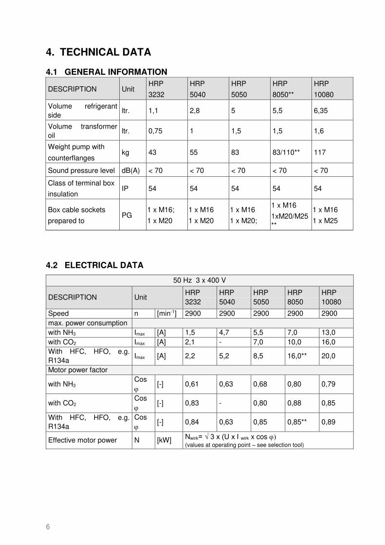
4.1 GENERAL INFORMATION
4.2 ELECTRICAL DATA
50 Hz 3 x 400 V
DESCRIPTION Unit HRP HRP HRP HRP HRP 3232 5040 5050 8050 10080
Speed n [min-1] 2900 2900 2900 2900 2900 max. power consumption with NH3 Imax [A] 1,5 4,7 5,5 7,0 13,0 with CO2 Imax [A] 2,1 - 7,0 10,0 16,0 With HFC, HFO, e.g. R134a
Imax [A] 2,2 5,2 8,5 16,0** 20,0
Motor power factor
with NH3 Cos
[-] 0,61 0,63 0,68 0,80 0,79
with CO2 Cos
[-] 0,83 - 0,80 0,88 0,85
With HFC, HFO, e.g. R134a
Cos
[-] 0,84 0,63 0,85 0,85** 0,89
Effective motor power N [kW] Nwirk= √ 3 x (U x I wirk x cos ) (values at operating point – see selection tool)
DESCRIPTION Unit HRP
3232
HRP
5040
HRP
5050
HRP
8050**
HRP
10080
Volume refrigerant side
ltr. 1,1 2,8 5 5,5 6,35
Volume transformer oil
ltr. 0,75 1 1,5 1,5 1,6
Weight pump with kg 43 55 83 83/110** 117
counterflanges
Sound pressure level dB(A) < 70 < 70 < 70 < 70 < 70
Class of terminal box
insulation IP 54 54 54 54 54
Box cable sockets
prepared to PG
1 x M16;
1 x M20
1 x M16
1 x M20
1 x M16
1 x M20;
1 x M16
1xM20/M25**
1 x M16
1 x M25

7
60 Hz 3 x 460 V
DESCRIPTION Unit HRP HRP HRP HRP HRP 3232 5040 5050 8050 10080
Speed n [min-1] 3500 3500 3500 3500 3500 max. power consumption with NH3 Imax [A] 2,0 6,2 7,3 10,0 16,0 with CO2 Imax [A] 2,6 - 9,5 16,0 24,0 With HFC, HFO, e.g. R134a
Imax [A] 2,9 6,9 11,5 23,5** 28,0
Motor power factor
with NH3 Cos
[-] 0,88 0,86 0,87 0,90 0,90
with CO2 Cos
[-] 0,92 - 0,90 0,90 0,93
With HFC, HFO, e.g. R134a
Cos
[-] 0,93 0,86 0,91 0,85** 0,93
Effective motor power N [kW] Nwirk= √ 3 x (U x I wirk x cos ) (values at operating point – see selection tool)
* Measure the maximum current during commissioning and set the overload protection to this value, do not exceed Imax for the relevant refrigerant.
** Model HRP8050 requires for HFCs and HFO, e.g. R134a a special motor with the dimensions and data from HRP10080
8
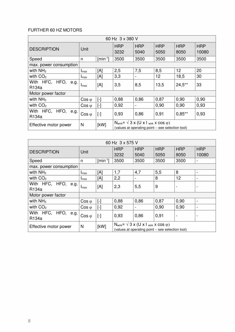
FURTHER 60 HZ MOTORS
60 Hz 3 x 380 V
DESCRIPTION Unit HRP HRP HRP HRP HRP 3232 5040 5050 8050 10080
Speed n [min-1] 3500 3500 3500 3500 3500 max. power consumption with NH3 Imax [A] 2,5 7,5 8,5 12 20 with CO2 Imax [A] 3,3 - 12 18,5 30 With HFC, HFO, e.g. R134a
Imax [A] 3,5 8,5 13,5 24,5** 33
Motor power factor with NH3 Cos [-] 0,88 0,86 0,87 0,90 0,90 with CO2 Cos [-] 0,92 - 0,90 0,90 0,93 With HFC, HFO, e.g. R134a
Cos [-] 0,93 0,86 0,91 0,85** 0,93
Effective motor power N [kW] Nwirk= √ 3 x (U x I wirk x cos ) (values at operating point – see selection tool)
60 Hz 3 x 575 V
DESCRIPTION Unit HRP HRP HRP HRP HRP 3232 5040 5050 8050 10080
Speed n [min-1] 3500 3500 3500 3500 - max. power consumption with NH3 Imax [A] 1,7 4,7 5,5 8 - with CO2 Imax [A] 2,2 - 8 12 - With HFC, HFO, e.g. R134a
Imax [A] 2,3 5,5 9 - -
Motor power factor with NH3 Cos [-] 0,88 0,86 0,87 0,90 - with CO2 Cos [-] 0,92 - 0,90 0,90 - With HFC, HFO, e.g. R134a
Cos [-] 0,93 0,86 0,91 - -
Effective motor power N [kW] Nwirk= √ 3 x (U x I wirk x cos ) (values at operating point – see selection tool)

9
4.3 MATERIALS
Pump housing: EN-GJS-400-18-LT
Stator: steel / copper
Rotor: steel/aluminium
Bearings: PTFE
Shaft: C 35+C
Motor can: 1.4301
Impellers: stainless steel / AL-Bronze (only CO2)
Main bolts: 8.8
Counter flanges: P355NL1 or C22.8
Bolts for counter flanges: 8.8
Gaskets soft gasket asbestos free
Transformer oil Fuchs Renolin Eltec
Painting system: W 9.1 + W 9.2
W 9.1 + W 9.2 = 2 k epoxy finish according to DIN ISO 12944/5, RAL 7001
4.4 PRESSURE RANGE
25 bar models
40 bar models
65 bar models
90 bar models
Design pressure (inside pump housing, motor can and stator housing)
25 40 65 90
Test pressure (with oil) [bar] 60 60 98 135
Allowable pressure range [bar]
25 (+50 / -10°C) 18,75 (-10 / -60°C)
40 (+50 / -10°C) 30 (-10 / -60°C)
65 (+50 / -10°C) 48,75 (-10 / -60°C)
90 (+50 / -10°C) 67,5 (-10 / -60°C)
For pressure testing with oil FUCHS Reniso Synth 68 is used.

10
The following table gives an overview of available standard and special pump types. Futher pump types are under development.
Nenndruck und verfügbare Pumpen / Design pressure and available pumps
Frequency Design
Press. Refrigerant
pump type
[Hz] [bar]
50 / 60 25 NH3, CO2 HRP3232 HRP5040 HRP5050 HRP8050 HRP10080
50 / 60
25 40
Other HFC, HFO
Standard
Standard Standard
Standard
Standard NH3, CO2 Special
40 Other HFC,
HFO Not
available
Standard Special
65 All refrigerants Not
available Not
available Not available
90 Only CO2 Not
available Standard Standard

11
4.5 DIMENSIONS
Fig. 1 HRP 3232

12
HRP 5040 5050 8050 10080
L 540 520 555 725
B 260 310 310 355
H 283 349 351 362
a1 150 180 180 180
a2 228 234 255 302
a3 196 170 170 290
b1 105 133 133 133
b2 154 174 174 222
c 53 53 66 70
d1 60,3 60,3 88,9 114,3
d2 48,3 60,3 60,3 88,9
l1 155 155 178 212
m1 115 145 145 145
m2 168 204 206 217
m3 130 190 190 190
HRP 5040 5050 8050 10080
f1 343 343 470 466
f2 346 343 343 ---
f3 376 373 373 472
h1 138 138 179 179
h2 141 138 138 179
Fig. 2a HRP 5040/5050/8050/10080

13
Fig. 2b HRP 5050-90 / 8050-90
14
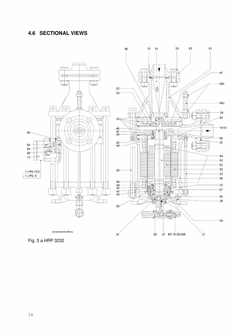
4.6 SECTIONAL VIEWS
Fig. 3 a HRP 3232
15
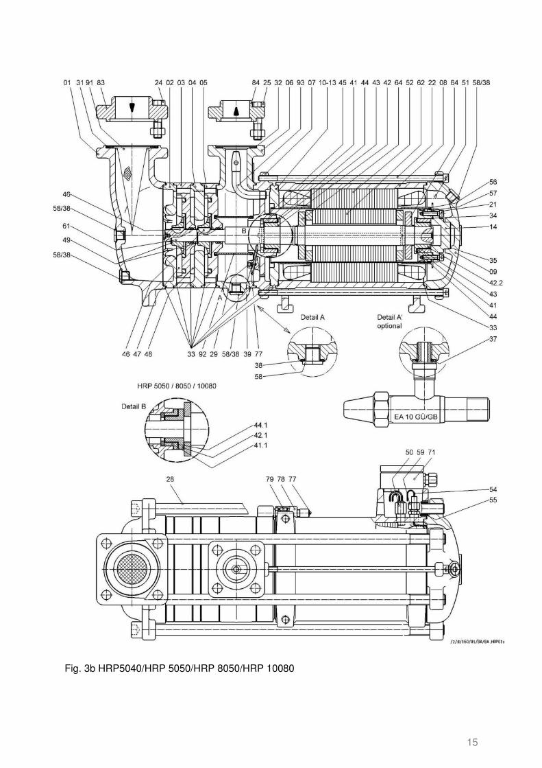
Fig. 3b HRP5040/HRP 5050/HRP 8050/HRP 10080

16
Fig. 3c HRP 5050-90 / HRP 8050-90
17
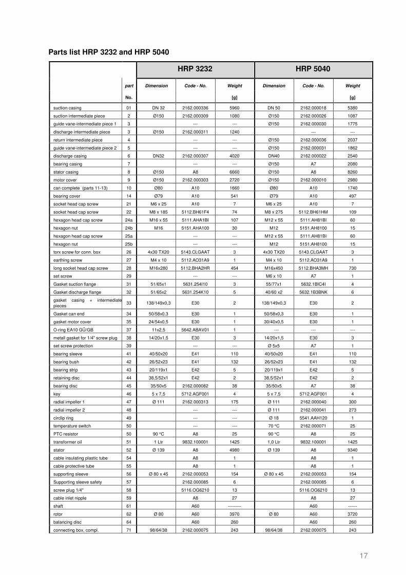
Parts list HRP 3232 and HRP 5040
HRP 3232 HRP 5040
part Dimension Code - No. Weight Dimension Code - No. Weight
No. [g] [g]
suction casing 01 DN 32 2162.000336 5960 DN 50 2162.000018 5380
suction intermediate piece 2 Ø150 2162.000309 1080 Ø150 2162.000026 1087
guide vane-intermediate piece 1 3 --- --- Ø150 2162.000030 1775
discharge intermediate piece 3 Ø150 2162.000311 1240 --- ---
return intermediate piece 4 --- --- Ø150 2162.000036 2037
guide vane-intermediate piece 2 5 --- --- Ø150 2162.000031 1862
discharge casing 6 DN32 2162.000307 4020 DN40 2162.000022 2540
bearing casing 7 --- --- Ø150 A7 2080
stator casing 8 Ø150 A8 6660 Ø150 A8 8260
motor cover 9 Ø150 2162.000303 2720 Ø150 2162.000010 2980
can complete (parts 11-13) 10 Ø80 A10 1660 Ø80 A10 1740
bearing cover 14 Ø79 A10 541 Ø79 A10 497
socket head cap screw 21 M6 x 25 A10 7 M6 x 25 A10 7
socket head cap screw 22 M8 x 185 5112.BH61F4 74 M8 x 275 5112.BH61HM 109
hexagon head cap screw 24a M16 x 55 5111.AHA1BI 107 M12 x 55 5111.AH81BI 60
hexagon nut 24b M16 5151.AHA100 30 M12 5151.AH8100 15
hexagon head cap screw 25a --- --- M12 x 55 5111.AH81BI 60
hexagon nut 25b --- --- M12 5151.AH8100 15
torx screw for conn. box 26 4x30 TX20 5143.CLGAAT 3 4x30 TX20 5143.CLGAAT 3
earthing screw 27 M4 x 10 5112.AO31A9 1 M4 x 10 5112.AO31A9 1
long socket head cap screw 28 M16x280 5112.BHA2HR 454 M16x450 5112.BHA3MH 730
set screw 29 --- --- M6 x 10 A7 1
Gasket suction flange 31 51/65x1 5631.254I10 3 55/77x1 5632.1BIC4I 4
Gasket discharge flange 32 51/65x2 5631.254K10 5 40/60 x2 5632.1B3BNK 6
gasket casing + intermediate pieces
33 138/149x0,3 E30 2 138/149x0,3 E30 2
Gasket can end 34 50/58x0,3 E30 1 50/58x0,3 E30 1
gasket motor cover 35 24/54x0,5 E30 1 30/40x0,5 E30 1
O-ring EA10 GÜ/GB 37 11x2,5 5642.ABAV01 1 --- --- ---
metall gasket for 1/4" screw plug 38 14/20x1,5 E30 3 14/20x1,5 E30 3
set screw protection 39 --- --- Ø 5x5 A7 1
bearing sleeve 41 40/50x20 E41 110 40/50x20 E41 110
bearing bush 42 26/52x23 E41 132 26/52x23 E41 132
bearing strip 43 20/119x1 E42 5 20/119x1 E42 5
retaining disc 44 38,5/52x1 E42 2 38,5/52x1 E42 2
bearing disc 45 35/50x5 2162.000082 38 35/50x5 A7 38
key 46 5 x 7,5 5712.AGF001 4 5 x 7,5 5712.AGF001 4
radial impeller 1 47 Ø 111 2162.000313 175 Ø 111 2162.000040 300
radial impeller 2 48 --- --- Ø 111 2162.000041 273
circlip ring 49 --- --- Ø 18 5541.AAH120 1
temperature switch 50 --- --- 70 °C 2162.000071 25
PTC resistor 50 90 °C A8 25 90 °C A8 25
transformer oil 51 1 Ltr 9832.100001 1425 1,0 Ltr 9832.100001 1425
stator 52 Ø 139 A8 4980 Ø 139 A8 9340
cable insulating plastic tube 54 A8 1 A8 1
cable protective tube 55 A8 1 A8 1
supporting sleeve 56 Ø 80 x 45 2162.000053 154 Ø 80 x 45 2162.000053 154
Supporting sleeve safety 57 2162.000085 6 2162.000085 6
screw plug 1/4" 58 5116.OG6210 13 5116.OG6210 13
cable inlet nipple 59 A8 27 A8 27
shaft 61 A60 --------- A60 ------
rotor 62 Ø 80 A60 3970 Ø 80 A60 3720
balancing disc 64 A60 260 A60 260
connecting box, compl. 71 98/64/38 2162.000075 243 98/64/38 2162.000075 243

18
backup fuse for PTC resistor 71a 2591.000101 1 2591.000101 1
sensor wire 77a --- --- A7 1
sensor wire insulation 77b --- --- A7 1
sensor connecting cover 78 --- --- A7 15
sensor inlet nipple 79 --- --- A7 27
counterflange suction side 83 DN32 E21 1720 DN50 E21 1194
counterflange discharge side 84 DN32 E22 1720 DN40 E22 713
threaded bar 86a M12x180 5122.BFAJEZ 127 M12x180 5122.BFAJEZ 127
hexagon nut 86b M12 5151.AH8100 15 M12 5151.AH8100 15
limpet washer 86c Ø30/13x3 5161.K11100 12 Ø30/13x3 5161.K11100 12
suction strainer 91 Ø50x125 2196.000002 13 Ø50x125 2196.000002 13
bearing filter 92 --- --- Ø57x57 2162.000084 54
ejector 93 --- --- A7 80

19
HRP replacement assemblies and spare part sets
HRP3232 HRP5040
Part Article No. Weight [g] Part Article No. Weight [g]
bearing casing with parts: A7 2162.A00092 2162.A00090
HRP 3232: 6;41; 45; E30; E42; 51;
4938
HRP 5040: 7;41; 45; E30; E42; 51, 77-79; 29; 39; 93
2330
stator with parts: A8 2162.A00116 2162.A00114
HRP 3232: 08;52;54;55;59;71;E30;E42;51
6360
HRP5040: 08;50;52;54;55;59;71;E30;E42;51
17650
motor can with parts: A10 2162.A00053 3161 2162.A00051 2354
10;41;14;21; E30; E42; 51
Balanced shaft, rotor+impellers: --- A60 2162.A00010 6453
61-64; 42; 46; 47, 48, 49; E30; E42; 51
shaft with rotor with parts: A61 2162.A00118 2162.A00112
HRP 3232: 61-64; 42; 46; E30; E42; 51
5460
HRP 5040: 61-64; 42; 46; 49; E30; E42; 51 5880
counterfl. suct. incl. mount.mat. E21 2162.000500 2212 E21 2162.000145 1600
4x 24a, 4x 24b, 2x31, 83
counterfl. Deliv. incl. mount.mat E22 2162.000500 2212 E22 2162.000144 967
4x 25a, 4x25b, 1x32, 84
set of gaskets: number x no. E30
2162.000170
2162.000124
HRP 3232: 6x33, 1x34, 2x38
28
HRP 5040: 2x31; 1x32; 9x33 ; 1x34; 1x35; 4x38
37
bearing sleeve (41) + -bush (42) E41 2162.000126 241 2162.000126 241
bearing strips (2x43) +
retaining discs (2x44) E42 2162.000127 7 2162.000127 7

20
Parts list HRP5050
HRP 5050 HRP 5050 CO2
part dimension code - no. Weight [g] dimension code - no. Weight [g]
suction casing 1 DN 50 2162.001002 7440 DN 50 2162.001002 7440
suction intermediate piece 2 Ø196 2162.001004 2420 Ø196 2162.001004 2420
guide vane-interm. piece 1 3 Ø196 2162.001007 3100 Ø196 2162.001013 3100
return intermediate piece 4 Ø196 2162.001006 5040 Ø196 2162.001006 5040
guide vane-interm. piece 2 5 Ø196 2162.001008 3470 Ø196 2162.001008 3470
guide plate for interm. piece 2 5a 2162.002041 126 2162.002041 126
..Screw for guide plate 5b M6 x 10 5112.BC51A9 5 M6 x 10 5112.BC51A9 5
discharge casing 6 DN 50 2162.000024 4080 DN 50 2162.000024 4080
bearing casing 7 Ø196 A7 2880 Ø196 A7- CO2 2880
stator casing 8 Ø196 A8 10550 Ø196 A8- CO2 10550
motor cover 9 Ø196 2162.000012 3640 Ø196 2162.000012 3640
can compl. (incl. parts 11-13) 10 Ø95 A10 3055 Ø95 A10- CO2 3055
bearing cover 14 Ø79 A10 497 Ø79 A10- CO2 497
socket head cap screw 21 M6 x 25 A10 7 M6 x 25 A10- CO2 7
socket head cap screw 22 M8 x 245 5112.BH61GS 98 M8 x 245 5112.BH61GS 98
hexagon head cap screw 24a M16 x 65 5111.AH81BI 126 M16 x 65 5111.AH81BI 126
hexagon nut 24b M16 5151AH8100 30 M16 5151AH8100 30
hexagon head cap screw 25a M12 x 55 5111.AH81BI 60 M12 x 55 5111.AH81BI 60
hexagon nut 25b M12 5151.AH8100 15 M12 5151.AH8100 15
torx screw for conn. box 26 4x30 TX20 5143.CLGAAT 3 4x30 TX20 5143.CLGAAT 3
earthing screw 27 M4 x 10 5112.AO31A9 1 M4 x 10 5112.AO31A9 1
long socket head cap screw 28 M16x450 5112.BHA3MH 730 M16x450 5112.BHA3MH 730
set screw 29 M6 x 10 A7 1 M6 x 10 A7- CO2 1
joint suction flange 31 55/77x2 5632.1BIC4I 4 55/77x2 5632.1BIC4I 4
joint discharge flange 32 55/77x2 5632.1BIC4K 8 55/77x2 5632.1BIC4K 8
joint casing + interm. pieces 33 180/195x0,3 E30 3 180/195x0,3 E30 3
joint can end 34 50/58x0,3 E30 1 50/58x0,3 E30 1
joint motor cover 35 30/40x0,5 E30 1 30/40x0,5 E30 1
joint 1/4" screw plug 38 14/20x1,5 E30 3 14/20x1,5 E30 3
set screw protection 39 Ø 5x5 A7 1 Ø 5x5 A7- CO2 1
bearing sleeve (motor side) 41 40/50x20 E41.1 108 40/50x20 E41.1 - CO2 108
bearing sleeve II (pump side9 41.1 40/60x20 E41.1 147 --- --- ---
bearing sleeve III (pump side) 41.1- CO2 --- --- --- 40/70x20 E41.1 - CO2 147
bearing bush II (pump side) 42.1 26/60x28 E41.1 237 --- --- ---
bearing bush II.3 (pump side) 42.1- CO2 --- --- --- 26/60x28 E41.1 - CO2 218
bearing bush I.2 (motor side) 42.2 26/52x23 E41.1 124 26/52x23 E41.1 - CO2 124
bearing strip 43 20/119x1 E42.1 5 20/119x1 E42.1- CO2 5
retaining disc (motor side) 44 38,5/52x1 E42.1 2 38,5/52x1 E42.1- CO2 2
retaining disc II (pump side) 44.1 39,5/60x1 E42.1 4 --- --- ---
retaining disc IV (pump side) 44.1- CO2 --- --- --- 41,5/70x3 E42.1- CO2 6
bearing disc 45 35/50x5 A7 38 35/50x5 A7- CO2 38
key 46 6 x 10 5712.AHH001 9 6 x 10 5712.AHH001 9
radial impeller 1 47 Ø 136 2162.001009 475 Ø 136 2162.001011 475
radial impeller 2 48 Ø 136 2162.001010 460 Ø 136 2162.001012 460
circlip ring 49 Ø 26 5541.AAP120 2 --- --- ---
PTC resistor wire outlet 50 90 °C A8 25 90 °C A8- CO2 25
transformer oil, 2 L required 51 1,0 L 9832.100001 1425 1,0 L 9832.100001 1425
stator 52 Ø 180 A8 15000 Ø 180 A8- CO2 15000
cable insulating plastic tube 54 A8 1 A8- CO2 1
cable protective tube 55 A8 1 A8- CO2 1
supporting sleeve 56 Ø101,6 x 47 2162.000054 298 Ø101,6 x 47 2162.000054 298
supporting sleeve safety 57 2162.000085 6 2162.000085 6
screw plug 1/4" 58 5116.OG6210 13 5116.OG6210 13
cable inlet nipple 59 A8 27 A8- CO2 27
shaft 61 A60 --- A60- CO2 ---
rotor 62 Ø 95 A60 --- Ø 95 A60- CO2 ---
balancing disc 64 A60 --- A60- CO2 ---
connecting box, compl. 71 98/64/38 2162.000075 243 98/64/38 2162.000075 243
backup fuse for PTC resistor 71a 2591.000101 1 2591.000101 1

21
sensor wire 77a A7 1 A7- CO2 1
sensor wire insulation 77b A7 1 A7- CO2 1
sensor connecting cover 78 A7 15 A7- CO2 15
sensor inlet nipple 79 A7 27 A7- CO2 27
counterflange suction side 83 DN50 E21 1194 DN50 E21 1194
counterflange discharge side 84 DN50 E22 1194 DN50 E22 1194
threaded bar 86a M12x180 5122.BFAJEZ 127 M12x180 5122.BFAJEZ 127
hexagon nut 86b M12 5151.AH8100 15 M12 5151.AH8100 15
limpet washer 86c Ø30/13x3 5161.K11100 12 Ø30/13x3 5161.K11100 12
Conical filter, suction side 91 Ø50x125 2196.000002 13 Ø50x125 2196.000002 13
bearing filter 92 Ø57x57 2162.000084 54 Ø57x57 2162.000213 54
ejector 93 A7 80 A7- CO2 80
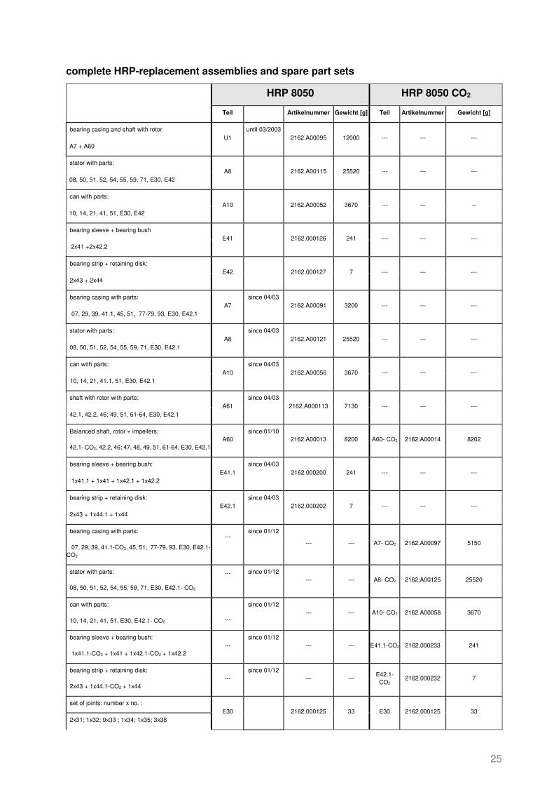
complete HRP-replacement assemblies and spare part sets
HRP 5050 HRP 5050 CO2
Teil Artikelnummer Gewicht [g] Artikelnummer Gewicht [g]
bearing casing and shaft with rotor U1 2162.A00093 12000 --- --- ---
A7 + A60 until 3/2003
stator with parts: A8 2162.A00117 25520 --- --- ---
08, 50, 51, 52, 54, 55, 59, 71, E30, E42
Motor can with parts: A10 2162.A00050 3670 --- --- --
10, 14, 21, 41, 51, E30, E42
bearing sleeve + bearing bush, parts: E41 2162.000126 241 ---- --- ---
2x41 +2x42
Bearing strip + retaining disks: E42 2162.000127 7 --- --- ---
2x43 + 2x44
bearing casing with parts: A7 2162.A00088 3200 --- --- ---
07, 29, 39, 41.1, 45, 51, 77-79, 93, E30, E42.1 since 04/03
stator with parts A8 2162.A00120 25520 --- --- ---
08, 50, 51, 52, 54, 55, 59, 71, E30, E42.1 since 04/03
Motor can with parts: A10 2162.A00054 3670 --- --- ---
10, 14, 21, 41.1, 51, E30, E42.1 since 04/03
shaft with rotor with parts: A61 2162.A00009 8750 --- --- ---
42, 42.1, 46; 49, 51, 61-64, E30, E42.1 since 04/03
Balanced shaft, rotor + impellers: A60 2162.A00011 9685 A60- CO2 2162.A00012 9685
42.2, 42.1, 46; 47, 48, 49, 51, 61-64, E30, E42.1 since 01/10
bearing sleeve + bearing bush E41.1 2162.000200 241 E41.1
CO2 2162.000230
241
1x41.1 + 1x41 + 1x42.1 + 1x42.2 since 04/03
bearing strips + retaining disks E42.1 2162.000202 7 E42.1 2162.000202 7
2x43 + 1x44.1 + 1x44 since 04/03
bearing casing with parts:
--- --- A7 - CO2 2162.A00096
5150
07, 29, 39, 41.1-CO2, 45, 51, 77-79, 93, E30, E42.1- CO2 since 01/12

22
stator with parts
--- --- A8- CO2 2162.A00124
25520
08, 50, 51, 52, 54, 55, 59, 71, E30, E42.1- CO2 since 01/12
Motor can with parts:
--- --- A10- CO2 2162.A00057
3670
10, 14, 21, 41, 51, E30, E42.1- CO2 since 01/12
bearing sleeve + bearing bush --- --- E41.1- CO2 2162.000233 241
1x41.1 - CO2+ 1x41 + 1x42.1- CO2 + 1x42.2 since 01/12
bearing strips + retaining disks: --- --- E42.1- CO2 2162.000232 7
2x43 + 1x44.1-CO2 + 1x44 since 01/12
set of gaskets: number x no. E30 2162.001200 33 E30 2162.001200 33
2x31; 1x32; 9x33 ; 1x34; 1x35; 3x38
..Counterflange incl. mount. mat. E21 2162.000145 1600 E21 2162.000145 1600
4 x 24a, 4 x 24b, 2 x 31, 83
..Counterflange incl. mount. mat. E22 2162.000145 1600 E22 2162.000145 1600
4 x 25a, 4 x 25b, 1 x 32, 84
Blindflange suction side --- 2162.009100 2650 --- 2162.009100 2650
Inkl. Befestigungsmaterial
Blindflange pressure side --- 2162.009100 2650 --- 2162.009100 2650
including mounting material

23
Parts list HRP8050
HRP 8050 HRP8050 CO2
part dimension code - no. Weight [g] dimension code - no. Weight [g]
suction casing 1 DN 80 2162.000178 9040 DN 80 2162.000178 9040
suction intermediate piece 2 Ø196 2162.000028 2276 Ø196 2162.000028 2276
guide vane-interm. piece 1 3 Ø196 2162.000033 3764 Ø196 2162.009002 3764
return intermediate piece 4 Ø196 2162.000038 3684 Ø196 2162.000038 3684
guide vane-interm. piece 2 5 Ø196 2162.000034 3854 Ø196 2162.000034 3854
guide plate for interm. piece 2 5a 2162.002041 126 2162.002041 126
..Screw for guide plate 5b M6 x 10 5112.BC51A9 5 M6 x 10 5112.BC51A9 5
discharge casing 6 DN 50 2162.000024 4080 DN 50 2162.000024 4080
bearing casing 7 Ø196 A7 2880 Ø196 A7- CO2 2880
stator casing 8 Ø196 A8 10550 Ø196 A8- CO2 10550
motor cover 9 Ø196 2162.000012 3640 Ø196 2162.000012 3640
can compl. (incl. parts 11-13) 10 Ø95 A10 3055 Ø95 A10- CO2 3055
bearing cover 14 Ø79 A10 497 Ø79 A10- CO2 497
socket head cap screw 21 M6 x 25 A10 7 M6 x 25 A10- CO2 7
socket head cap screw 22 M8 x 245 5112.BH61GS 98 M8 x 245 5112.BH61GS 98
hexagon head cap screw 24a M16 x 65 5111.AHA1BS 126 M16 x 65 5111.AHA1BS 126
hexagon nut 24b M16 5151AHA100 30 M16 5151AHA100 30
hexagon head cap screw 25a M12 x 55 5111.AH81BI 60 M12 x 55 5111.AH81BI 60
hexagon nut 25b M12 5151.AH8100 15 M12 5151.AH8100 15
torx screw for conn. box 26 4x30 TX20 5143.CLGAAT 3 4x30 TX20 5143.CLGAAT 3
earthing screw 27 M4 x 10 5112.AO31A9 1 M4 x 10 5112.AO31A9 1
long socket head cap screw 28 M16x450 5112.BHA3MH 730 M16x450 5112.BHA3MH 730
set screw 29 M6 x 10 A7 1 M6 x 10 A7- CO2 1
joint suction flange 31 77/100 x1 5632.1C4CRI 6 77/100 x1 5632.1C4CRI 6
joint discharge flange 32 55/77x2 5632.1BIC4K 8 55/77x2 5632.1BIC4K 8
joint casing + interm. pieces 33 180/195x0,3 E30 3 180/195x0,3 E30 3
joint can end 34 50/58x0,3 E30 1 50/58x0,3 E30 1
joint motor cover 35 30/40x0,5 E30 1 30/40x0,5 E30 1
joint 1/4" screw plug 38 14/20x1,5 E30 3 14/20x1,5 E30 3
set screw protection 39 Ø 5x5 A7 1 Ø 5x5 A7- CO2 1
bearing sleeve I.2 (motor side) 41 40/50x20 E41.1 110 40/50x20 E41.1 – CO2 110
bearing sleeve II.2 (pump side) 41.1 40/60x20 E41.1 150 --- --- ---
bearing sleeve III (pump side) 41.1-CO2 --- --- --- 40/70x20 E41.1 – CO2 147
bearing bush II (pump side) 42.1 26/60x28 E41.1 240 --- --- ---
bearing bush II.3 (pump side) 42.1-CO2 --- --- --- 26/60x28 E41.1 – CO2 220
Bearing bush I.2 (motor side) 42.2 26/52x23 E41.1 125 26/52x23 E41.1 – CO2 125
bearing strip 43 20/119x1 E42.1 5 20/119x1 E42.1- CO2 5
retaining disc 44 38,5/52x1 E42.1 2 38,5/52x1 E42.1- CO2 2
retaining disc II 44.1 39,5/60x1 E42.1 4 --- --- ---
retaining disc II 44.1-CO2 --- --- --- 41,5/70x3 E42.1- CO2 6
bearing disc 45 35/50x5 A7 38 35/50x5 A7- CO2 38
key 46 6 x 10 5712.AHH001 9 6 x 10 5712.AHH001 9
radial impeller 1 47 Ø 136 2162.000043 557 Ø 136 2162.009000 558
radial impeller 2 48 Ø 136 2162.000044 513 Ø 136 2162.009001 514
circlip ring 49 Ø 26 5541.AAP120 2 --- --- ---
PTC resistor wire outlet 50 90 °C A8 --- 90 °C A8- CO2 ---
transformer oil, (2 L required) 51 1,0 L 9832.100001 1425 1,0 L 9832.100001 1425
stator 52 Ø 180 A8 15000 Ø 180 A8- CO2 15000
cable insulating plastic tube 54 --- A8 1 --- A8- CO2 1
cable protective tube 55 --- A8 1 --- A8- CO2 1
supporting sleeve 56 Ø101,6 x 47 2162.000054 298 Ø101,6 x 47 2162.000054 298
supporting sleeve safety 57 --- 2162.000085 6 --- 2162.000085 6
screw plug 1/4" 58 --- 5116.OG6210 13 --- 5116.OG6210 13
cable inlet nipple 59 --- A8 --- --- A8- CO2 ---
shaft 61 --- A60 --- --- A60 – CO2 ---
rotor 62 Ø 95 A60 3700 Ø 95 A60 – CO2 3700
balancing disc 64 A60 260 A60 – CO2 260
connecting box, compl. 71 98/64/38 2162.000075 243 98/64/38 2162.000075 243
backup fuse for PTC resistor 71a --- 2591.000101 1 --- 2591.000101 1

24
sensor wire 77a --- A7 1 --- A7- CO2 1
sensor wire insulation 77b --- A7 1 --- A7- CO2 1
sensor connecting cover 78 --- A7 15 --- A7- CO2 15
sensor inlet nipple 79 --- A7 27 --- A7- CO2 27
counterflange suction side 83 DN80 E21 1625 DN80 E21 1625
counterflange discharge side 84 DN50 E22 1194 DN50 E22 1194
threaded bar 86a M12x180 5122.BFAJEZ 127 M12x180 5122.BFAJEZ 127
hexagon nut 86b M12 5151.AH8100 15 M12 5151.AH8100 15
limpet washer 86c Ø30/13x3 5161.K11100 12 Ø30/13x3 5161.K11100 12
Conical filter, suction side 91 Ø83/76x160 2196.000004 17 Ø83/76x160 2196.000004 17
bearing filter 92 Ø57x57 2162.000084 54 Ø57x57 2162.000213 54
ejector 93 --- A7 80 --- A7- CO2 80
25
complete HRP-replacement assemblies and spare part sets
HRP 8050 HRP 8050 CO2
Teil Artikelnummer Gewicht [g] Teil Artikelnummer Gewicht [g]
bearing casing and shaft with rotor U1
until 03/2003 2162.A00095 12000 --- --- ---
A7 + A60
stator with parts: A8
2162.A00115 25520 --- --- ---
08, 50, 51, 52, 54, 55, 59, 71, E30, E42
can with parts: A10
2162.A00052 3670 --- --- --
10, 14, 21, 41, 51, E30, E42
bearing sleeve + bearing bush E41
2162.000126 241 ---- --- ---
2x41 +2x42.2
bearing strip + retaining disk: E42
2162.000127 7 --- --- ---
2x43 + 2x44
bearing casing with parts: A7
since 04/03 2162.A00091 3200 --- --- ---
07, 29, 39, 41.1, 45, 51, 77-79, 93, E30, E42.1
stator with parts: A8
since 04/03 2162.A00121 25520 --- --- ---
08, 50, 51, 52, 54, 55, 59, 71, E30, E42.1
can with parts: A10
since 04/03 2162.A00056 3670 --- --- ---
10, 14, 21, 41.1, 51, E30, E42.1
shaft with rotor with parts: A61
since 04/03 2162.A000113 7130 --- --- ---
42.1, 42.2, 46; 49, 51, 61-64, E30, E42.1
Balanced shaft, rotor + impellers: A60
since 01/10 2162.A00013 8200 A60- CO2 2162.A00014 8202
42.1- CO2, 42.2, 46; 47, 48, 49, 51, 61-64, E30, E42.1
bearing sleeve + bearing bush: E41.1
since 04/03 2162.000200 241 --- --- ---
1x41.1 + 1x41 + 1x42.1 + 1x42.2
bearing strip + retaining disk: E42.1
since 04/03 2162.000202 7 --- --- ---
2x43 + 1x44.1 + 1x44
bearing casing with parts: ---
since 01/12
--- --- A7- CO2 2162.A00097 5150 07, 29, 39, 41.1-CO2, 45, 51, 77-79, 93, E30, E42.1- CO2
stator with parts: ---
since 01/12 --- --- A8- CO2 2162:A00125 25520
08, 50, 51, 52, 54, 55, 59, 71, E30, E42.1- CO2
can with parts:
---
since 01/12 --- --- A10- CO2 2162.A00058 3670
10, 14, 21, 41, 51, E30, E42.1- CO2
bearing sleeve + bearing bush: ---
since 01/12 --- --- E41.1-CO2 2162.000233 241
1x41.1-CO2 + 1x41 + 1x42.1-CO2 + 1x42.2
bearing strip + retaining disk: ---
since 01/12 --- ---
E42.1- CO2
2162.000232 7 2x43 + 1x44.1-CO2 + 1x44
set of joints: number x no. : E30
2162.000125 33 E30 2162.000125 33
2x31; 1x32; 9x33 ; 1x34; 1x35; 3x38

26
..Counterflange incl. mount. mat. E21
2162.000146 2531 E21 2162.000146 2531
4 x 24a, 4 x 24b, 2 x 31, 83,
..Counterflange incl. mount. mat. E22
2162.000145 1600 E22 2162.000145 1600
4 x 25a, 4 x 25b, 1 x 32, 84
Blindflange suction side ---
2162.002210 3500 --- 2162.002210 3500
Inkl. Befestigungsmaterial
Blindflange pressure side ---
2162.009100 2650 --- 2162.009100 2650
including mounting material

27
Parts list HRP8050-2
HRP 8050-2
part dimension code - no. Weight [g] suction casing 1 DN 80 2162.000178 9040 suction intermediate piece 2 Ø196 2162.000028 2276 guide vane-interm. piece 1 3 Ø196 2162.000033 3764 return intermediate piece 4 Ø196 2162.000038 3684 guide vane-interm. piece 2 5 Ø196 2162.000034 3854 guide plate for interm. piece 2 5a 2162.002041 126 ..Screw for guide plate 5b M6 x 10 5112.BC51A9 5 discharge casing 6 DN 50 2162.000024 4080 bearing casing 7 Ø196 A7-CO2 2880 stator casing 8 Ø196 A8 10550 motor cover 9 Ø196 2162.000012 3640 can compl. (incl. parts 11-13) 10 Ø95 A10 3055 bearing cover 14 Ø79 A10 497 socket head cap screw 21 M6 x 25 A10 7 socket head cap screw 22 M8 x 245 5112.BH61GS 98 hexagon head cap screw 24a M16 x 65 5111.AHA1BS 126 hexagon nut 24b M16 5151AHA100 30 hexagon head cap screw 25a M12 x 55 5111.AH81BI 60 hexagon nut 25b M12 5151.AH8100 15 torx screw for conn. box 26 4x30 TX20 5143.CLGAAT 3 earthing screw 27 M4 x 10 5112.AO31A9 1 long socket head cap screw 28a M16x285 5112.BHA2HW 462 Screw adaptor 28b M16 2162.002039 350 long socket head cap screw 28c M16x220 5112.BHA1G3 320 set screw 29 M6 x 10 A7-CO2 1 joint suction flange 31 77/100 x1 5632.1C4CRI 6 joint discharge flange 32 55/77x2 5632.1BIC4K 8 joint casing + interm. pieces 33 180/195x0,3 E30 3 joint can end 34 50/58x0,3 E30 1 joint motor cover 35 30/40x0,5 E30 1 joint 1/4" screw plug 38 14/20x1,5 E30 3 set screw protection 39 Ø 5x5 A7-CO2 1 Bearing sleeve I.2 (motor side) 41 40/50x20 E41.1-CO2 110 bearing sleeve III (pump side) 41.1-CO2 40/70x20 E41.1-CO2 147 bearing bush II.3 (pump side) 42.1 26/60x28 E41.1-CO2 220 bearing bush I.2 (motor side) 42.2 26/52x23 E41.1-CO2 125 bearing strip 43 20/119x1 E42.1-CO2 5 retaining disc (motor side) 44 38,5/52x1 E42.1-CO2 2 retaining disc IV (pump side) 44.1-CO2 41,5/70x3 E42.1-CO2 6 bearing disc 45 35/50x5 A7-CO2 38 key 46 6 x 10 5712.AHH001 9 radial impeller 1 47 Ø 136 2162.000043 557 radial impeller 2 48 Ø 136 2162.000044 513 circlip ring 49 Ø 26 5541.AAP120 2 PTC resistor wire outlet 50 90 °C A8 --- transformer oil, (2 L required) 51 1,0 L 9832.100001 1425 stator 52 Ø 180 A8 15000 cable insulating plastic tube 54 A8 1 cable protective tube 55 A8 1 supporting sleeve 56 Ø101,6 x 47 2162.000054 298 supporting sleeve safety 57 2162.000085 6 screw plug 1/4" 58 5116.OG6210 13 cable inlet nipple 59 A8 shaft 61 A60 --- rotor 62 Ø 95 A60 3700 balancing disc 64 A60 260 connecting box, compl. 71 98/64/38 2162.000075 243 backup fuse for PTC resistor 71a 2591.000101 1 sensor wire 77a A7-CO2 1 sensor wire insulation 77b A7-CO2 1 sensor connecting cover 78 A7-CO2 15 sensor inlet nipple 79 A7-CO2 27 counterflange suction side 83 DN80 E21 1625 counterflange discharge side 84 DN50 E22 1194 threaded bar 86a M12x180 5122.BFAJEZ 127 hexagon nut 86b M12 5151.AH8100 15 limpet washer 86c Ø30/13x3 5161.K11100 12 Conical filter, suction side 91 Ø83/76x160 2196.000004 17 bearing filter 92 Ø57x57 2162.000084 54 ejector 93 A7-CO2 80

28
complete HRP-replacement assemblies and spare part sets
HRP 8050-2
Part Article No. Weight [g]
bearing casing with parts: A7-CO2
2162.A00097 5150 07, 29, 39, 41.1, 45, 51, 77-79, 93, E30, E42.1
stator with parts: A8
2162.A00127 25520
08, 50, 51, 52, 54, 55, 59, 71, E30, E42.1
can with parts: A10
2162.A00060 3670
10, 14, 21, 41.1, 51, E30, E42.1
Balanced shaft, rotor + impellers:
A60
2162.A00019 7830 42.1, 42.2, 46; 47, 48, 49, 51, 61-64, E30, E42.1
bearing sleeve + bearing bush: E41.1-CO2
2162.000233 241
1x41.1 + 1x41 + 1x42.1 + 1x42.2
bearing strip + retaining disk: E42.1-CO2
2162.000232 7
2x43 + 1x44.1 + 1x44
set of joints: number x no. : E30
2162.000125 33
2x31; 1x32; 9x33 ; 1x34; 1x35; 3x38
Counterflange incl. mount. mat. E21
2162.000146 2531
..4 x 24a, 4 x 24b, 2 x 31, 83,
Counterflange incl. mount. mat. E22
2162.000145 1600
4 x 25a, 4 x 25b, 1 x 32, 84
Blindflange suction side ---
2162.002210 3500
including mounting material
Blindflange pressure side ---
2162.009100 2650
including mounting material

29
Parts list HRP10080
HRP 10080 HRP10080 CO2 part dimension code - no. Weight [g] dimension code - no. Weight [g] suction casing 1 DN 100 2162.002011 11420 DN 100 2162.002011 11420 suction intermediate piece 2 Ø196 2162.002015 2160 Ø196 2162.002015 2160 guide vane-interm. piece 1 3 Ø196 2162.002017 4760 Ø196 2162.002059 4760 return intermediate piece 4 Ø196 2162.002020 3940 Ø196 2162.002020 3940 guide vane-interm. piece 2 5 Ø196 2162.002018 3040 Ø196 2162.002018 3040 guide plate for interm. piece 2 5a 2162.002041 126 2162.002041 126 ..Screw for guide plate 5b M6 x 10 5112.BC51A9 5 M6 x 10 5112.BC51A9 5 discharge casing 6 DN 80 2162.002013 5720 DN 80 2162.002013 5720 bearing casing 7 Ø196 A7 2880 Ø196 A7- CO2 2880 stator casing 8 Ø196 A8 18000 Ø196 A8- CO2 10550 motor cover 9 Ø196 2162.000012 3640 Ø196 2162.000012 3640 can compl. (incl. parts 11-13) 10 Ø95 A10 3645 Ø95 A10- CO2 3645 bearing cover 14 Ø79 A10 497 Ø79 A10- CO2 497 socket head cap screw 21 M6 x 25 A10 7 M6 x 25 A10- CO2 7 socket head cap screw 22 M8 x 365 5112.BH61K4 143 M8 x 365 5112.BH61K4 143 hexagon head cap screw 24a M16 x 55 5111.AHA1BI 110 M16 x 55 5111.AHA1BI 110 hexagon nut 24b M16 5151.AHA100 30 M16 5151.AHA100 30 hexagon head cap screw 25a M 16 x 70 5111.AHA1BX 135 M 16 x 70 5111.AHA1BX 135 hexagon nut 25b M16 5151.AHA100 30 M16 5151.AHA100 30 torx screw for conn. box 26 4x30 TX20 5143.CLGAAT 3 4x30 TX20 5143.CLGAAT 3 earthing screw 27 M4 x 10 5112.AO31A9 1 M4 x 10 5112.AO31A9 1 long socket head cap screw 28a M16x285 5112.BHA2HW 462 M16x285 5112.BHA2HW 463 long socket head cap screw 28b M16 5112.002039 350 M16 5112.002039 350 set screw 29 M6 x 10 A7 1 M6 x 10 A7- CO2 1 joint suction flange 31 96/119x1 5632.1CNDAI 7 96/119x1 5632.1CNDAI 7 joint discharge flange 32 77/100x2 5632.1C4CRK 12 77/100x2 5632.1C4CRK 12 joint casing + interm. pieces 33 180/195x0,3 E30 3 180/195x0,3 E30 3 joint can end 34 50/58x0,3 E30 1 50/58x0,3 E30 1 joint motor cover 35 30/40x0,5 E30 1 30/40x0,5 E30 1 joint 1/4" screw plug 38 14/20x1,5 E30 3 14/20x1,5 E30 3 set screw protection 39 Ø 5x5 A7 1 Ø 5x5 A7- CO2 1 bearing sleeve I.2 (motor side) 41 40/50x20 E41.1 110 40/50x20 E41.1 – CO2 110 bearing sleeve II.2 (pump side) 41.1 40/60x20 E41.1 150 --- --- --- bearing sleeve III (pump side) 41.1-CO2 --- --- --- 40/70x20 E41.1 – CO2 147 bearing bush II (pump side) 42.1 26/60x28 E41.1 240 --- --- --- bearing bush II.3 (pump side) 42.1- CO2 --- --- --- 26/60x28 E41.1 – CO2 220 bearing bush I.2 (motor side) 42.2 26/52x23 E41.1 125 26/52x23 E41.1 – CO2 125 bearing strip 43 20/119x1 E42.1 5 20/119x1 E42.1- CO2 5 retaining disc (motor side) 44 38,5/52x1 E42.1 2 38,5/52x1 E42.1- CO2 2 retaining disc II (pump side) 44.1 39,5/60x1 E42.1 4 --- --- --- retaining disc IV (pump side) 44.1-CO2 --- --- --- 41,5/70x3 E42.1- CO2 6 bearing disc 45 35/50x5 A7 38 35/50x5 A7- CO2 38 key 46 6 x 10 5712.AHH001 9 6 x 10 5712.AHH001 9 radial impeller 1 47 Ø 136 A60 660 Ø 136 A60 – CO2 660 radial impeller 2 48 Ø 136 A60 520 Ø 136 A60 – CO2 520 circlip ring 49 Ø 26 5541.AAP120 2 --- --- --- PTC resistor wire outlet 50 90 °C A8 --- 90 °C A8- CO2 --- transformer oil, 2 L required 51 1,0 L 9832.100001 1425 1,0 L 9832.100001 1425 stator 52 Ø 180 A8 --- Ø 180 A8- CO2 --- cable insulating plastic tube 54 --- A8 1 --- A8- CO2 1 cable protective tube 55 --- A8 1 --- A8- CO2 1 supporting sleeve 56 Ø101,6 x 47 2162.000054 298 Ø101,6 x 47 2162.000054 298 supporting sleeve safety 57 --- 2162.000085 6 --- 2162.000085 6 screw plug 1/4" 58 --- 5116.OG6210 13 --- 5116.OG6210 13 cable inlet nipple 59 --- A8 --- A8- CO2 --- shaft 61 --- A60 --- --- A60 – CO2 --- rotor 62 Ø 95 A60 8300 Ø 95 A60 – CO2 8300 balancing disc 64 --- A60 260 A60 – CO2 260 connecting box, compl. 71 98/98/82 2162.002036 670 98/98/82 2162.002036 670 backup fuse for PTC resistor 71a --- 2591.000101 1 --- 2591.000101 1 sensor wire 77a --- A7 1 --- A7- CO2 1 sensor wire insulation 77b --- A7 1 --- A7- CO2 1 sensor connecting cover 78 --- A7 15 --- A7- CO2 15 sensor inlet nipple 79 --- A7 27 --- A7- CO2 27 counterflange suction side 83 DN 100 E21 2320 DN 100 E21 2320 counterflange discharge side 84 DN 80 E22 1625 DN 80 E22 1625 threaded bar 86a M12x180 5122.BFAJEZ 127 M12x180 5122.BFAJEZ 127 hexagon nut 86b M12 5151.AH8100 15 M12 5151.AH8100 15 limpet washer 86c Ø30/13x3 5161.K11100 12 Ø30/13x3 5161.K11100 12 Conical filter, suction side 91 Ø100x160 2196.000005 35 Ø100x160 2196.000005 35 bearing filter 92 Ø57x57 2162.000084 54 Ø57x57 2162.000213 54 ejector 93 A7 141 --- A7- CO2 141

30
complete HRP-replacement assemblies and spare part sets
HRP 10080 HRP 10080 CO2
Part Article No. Weight [g] Article No.r Weight [g]
bearing casing with parts:
A7
2162.A00089 3200 --- --- --- 07, 29, 39, 41.1, 45, 51, 77-79, 93, E30, E42.1
stator with parts: A8
2162.A02032 25520 --- --- ---
08, 50, 51, 52, 54, 55, 59, 71, E30, E42.1
can with parts: A10
2162.A02007 3670 --- --- ---
10, 14, 21, 41.1, 51, E30, E42.1
balanced shaft, rotor + impellers:
A60
since 01/10
2162.A00015 12588 --- --- --- 42.1, 42.2, 46; 47, 48, 49, 51, 61-64, E30, E42.1
bearing sleeve + bearing bush: E41.1
2162.000200 241 --- --- ---
1x41.1 + 1x41 + 1x42.1 + 1x42.2
bearing strip + retaining disk: E42.1
2162.000202 7 --- --- ---
2x43 + 1x44.1 + 1x44
bearing casing with parts:
---
since 01/12
--- --- A7- CO2 2162.A00098 5170 07, 29, 39, 41.1-CO2, 45, 51, 77-79, 93, E30, E42.1-CO2
stator with parts: ---
since 01/12 --- --- A8- CO2 2162.A00126 25520
08, 50, 51, 52, 54, 55, 59, 71, E30, E42.1
can with parts: ---
since 01/12 --- --- A10- CO2 2162.A00059 3670
10, 14, 21, 41.1, 51, E30, E42.1
balanced shaft, rotor + impellers:
---
since 01/12
--- --- A60-CO2 2162.A00018 12570 3, 42.1, 42.2, 46; 47, 48, 49, 51, 61-64, E30, E42.1- CO2
balanced shaft, rotor + impellers:
---
until 12/11
--- --- A62- CO2 2162.A00017 7810 42.1, 42.2, 46; 47, 48, 49, 51, 61-64, E30, E42.1-CO2
bearing sleeve + bearing bush:
---
since 01/12
--- --- E41.1- CO2 2162.000233 241 1x41.1 -CO2+ 1x41 + 1x42.1-CO2 + 1x42.2
bearing strip + retaining disk: ---
ab 01/2012 --- --- E42.1- CO2 2162.000232 7
2x43 + 1x44.1-CO2 + 1x44
set of joints: number x no. : E30
2162.002037 33 E30 2162.002037 33
2x31; 1x32; 9x33 ; 1x34; 1x35; 3x38
..counterflange incl. mount. mat. E21
2162.002038 3535 E21 2162.002038 3535
4 x 24a, 4 x 24b, 2 x 31, 83,
..counterflange incl. mount. mat. E22
2162.000146 2531 E22 2162.000146 2531
4 x 25a, 4 x 25b, 1 x 32, 84

31
Parts list HRP 5050-90 and HRP 8050-90
HRP 5050-90 HRP 8050-90
Part dimension code - no
Weight [g]
dimension code - no Weight
[g] suction casing 1 DN 80 2.162.004.004 18500 DN 80 2.162.004.004 18500
suction intermediate piece 2 Ø196 2.162.001.004 2400 Ø196 2.162.000.028 2250
guide vane-interm. piece 1 3 Ø196 2.162.001.013 3200 Ø196 2.162.009.002 4000
return intermediate piece 4 Ø196 2.162.001.006 5140 Ø196 2.162.000.038 3670
guide vane-interm. piece 2 5 Ø196 2.162.001.008 3520 Ø196 2.162.000.034 3880
guide plate for interm. piece 2 5a 2.162.002.041 124 2.162.002.041 124
Screw for guide plate 5b M6 x 10 5112.BC51A9 5 M6 x 10 5112.BC51A9 5
discharge casing 6 DN 50 2.162.004.006 7500 DN 50 2.162.004.006 7500
bearing casing 7 Ø196 E7- CO2 3500 Ø196 E7- CO2 3500
Drainage pipe 7a Ø25x35 E7- CO2 17 Ø25x35 E7- CO2 17
Coiled spring pins 7b 3x10 E7- CO2 0,3 3x10 E7- CO2 0,3
stator casing 8 Ø196 E8- CO2 14214 Ø196 E8- CO2 14214
motor cover 9 Ø196 2.162.004.010 13500 Ø196 2.162.004.010 13500
can compl. (incl. parts 11-13) 10 --- --- --- --- --- ---
bearing cover 14 --- --- --- --- --- ---
socket head cap screw 21 --- --- --- --- --- ---
socket head cap screw 22 --- --- --- --- --- ---
hexagon head cap screw 24a M16 x 65 5111.AHA1BS 126 M16 x 65 5111.AHA1BS 126
hexagon nut 24b M16 5151.AHA100 30 M16 5151.AHA100 30
hexagon head cap screw 25a M16 x 65 5111.AHA1BS 126 M16 x 65 5111.AHA1BS 126
hexagon nut 25b M16 5151.AHA100 30 M16 5151.AHA100 30
torx screw for conn. box 26 4x30 TX20 5143.CLGAAT 2 4x30 TX20 5143.CLGAAT 2
earthing screw 27 M4 x 10 5112.AO31A9 1,5 M4 x 10 5112.AO31A9 1,5
long socket head cap screw 28 M20 x 450 5112.BHC3MH 730 M20 x 450 5112.BHC3MH 730
set screw 29 --- --- --- --- --- ---
joint suction flange 31 77/100 x1 5632.1C4CRI 6 77/100 x1 5632.1C4CRI 6
joint discharge flange 32 55/77x2 5632.1BIC4K 8,5 55/77x2 5632.1BIC4K 8,5
joint casing + interm. pieces 33 180/195x0,3 E30 3 180/195x0,3 E30 3
joint can end 34 --- --- --- --- --- ---
joint motor cover 35 --- --- --- --- --- ---
joint 1/4" screw plug 38 14/20x1,5 E30 3 14/20x1,5 E30 3
set screw protection 39 --- --- --- --- --- ---
bearing sleeve I.2 (motor side) 41 40/50x20 E41.1 – CO2 150 40/50x20 E41.1 – CO2 150
bearing sleeve II.2 (pump side) 41.1 --- --- --- --- --- ---
bearing sleeve III (pump side) 41.1-CO2 40/70x20 E41.1 – CO2 147 40/70x20 E41.1 – CO2 147
bearing bush II (pump side) 42.1 --- --- --- --- --- ---
bearing bush II.3 (pump side) 42.1-CO2 26/60x28 E41.1 – CO2 220 26/60x28 E41.1 – CO2 220
Bearing bush I.2 (motor side) 42.2 26/52x23 E41.1 – CO2 120.5 26/52x23 E41.1 – CO2 120.5
bearing strip 43 20/119x1 E42.1- CO2 5 20/119x1 E42.1- CO2 5
retaining disc 44 38,5/52x1 E42.1- CO2 2 38,5/52x1 E42.1- CO2 2
retaining disc II 44.1 --- --- --- --- --- ---
retaining disc II 44.1-CO2 41,5/70x3 E42.1- CO2 6 41,5/70x3 E42.1- CO2 6
bearing disc 45 35/50x5 E7- CO2 38 35/50x5 E7- CO2 38
key 46 6 x 10 5712.AHH001 8,5 6 x 10 5712.AHH001 8,5
radial impeller 1 47 Ø 136 2.162.001.016 455 Ø 136 2.162.009.008 535
radial impeller 2 48 Ø 136 2.162.001.017 430 Ø 136 2.162.009.009 485
circlip ring 49 --- --- --- --- --- ---
PTC resistor wire outlet 50 90 °C E8- CO2 --- 90 °C E8- CO2 ---
transformer oil, (2 L required) 51 --- --- --- --- --- ---
stator 52 Ø 180 E8- CO2 15260 Ø 180 E8- CO2 15260
cable insulating plastic tube 54 --- E8- CO2 1 --- E8- CO2 1
cable protective tube 55 --- E8- CO2 1 --- E8- CO2 1
supporting sleeve 56 --- --- --- --- --- ---
supporting sleeve safety 57 --- --- --- --- --- ---
screw plug 1/4" 58 --- 5116.OG6210 15 --- 5116.OG6210 15
cable inlet nipple 59 --- E8- CO2 --- --- E8- CO2 ---
shaft 61 --- E60- CO2 --- --- E60- CO2 ---
rotor 62 Ø 95 E60- CO2 3700 Ø 95 E60- CO2 3700
balancing disc 64 E60- CO2 340 E60- CO2 340
connecting box, compl. 71 98/64/38 E60- CO2 678 98/64/38 E60- CO2 678
backup fuse for PTC resistor 71a --- 2.591.000.101 1 --- 2.591.000.101 1
sensor wire 77a --- --- --- --- --- ---
sensor wire insulation 77b --- --- --- --- --- ---
sensor connecting cover 78 --- --- --- --- --- ---
sensor inlet nipple 79 --- --- --- --- --- ---
counterflange suction side 83 DN80 E21 2560 DN80 E21 2560
counterflange discharge side 84 DN50 E22 1580 DN50 E22 1580
threaded bar 86a M12x180 5122.BFAJEZ 127 M12x180 5122.BFAJEZ 127
hexagon nut 86b M12 5151.AH8100 15 M12 5151.AH8100 15
limpet washer 86c Ø30/13x3 5161.A11100 6 Ø30/13x3 5161.A11100 6
Conical filter, suction side 91 Ø83/76x160 2.196.000.004 24 Ø83/76x160 2.196.000.004 24
bearing filter 92 Ø57x57 2.162.000.213 39 Ø57x57 2.162.000.213 39

32
ejector 93 --- E7- CO2 80 --- E7- CO2 80
Protective sleeve 94 Ø100x61 2.162.004.019 157 Ø100x61 2.162.004.019 157
Screws for protective sleeve 95 M4x16 5112.BC31AF 5 M4x16 5112.BC31AF 5
Cable gland 96 M25x1,5 5.191.000.125 15 M25x1,5 5.191.000.125 15
Cable gland 97 M16x1,5 5.191.000.116 6 M16x1,5 5.191.000.116 6
Sealing insert 98 Ø10 6491.EB0100 1 Ø10 6491.EB0100 1
complete HRP-replacement assemblies and spare part sets
HRP 5050-90 HRP 8050-90
Part code - no Weight
[g] Part code - no
Weight [g]
Balanced shaft, rotor + impellers: E60- CO2 2.162.004.022 9700 E60- CO2 2.162.004.023 9800
42.1- CO2, 42.2, 46; 47, 48, 61-64 bearing casing with parts:
E7- CO2 2.162.004.025 3400 E7- CO2 2.162.004.025 3400 07, 7a, 7b, 41.1-CO2, 45, 93 stator with parts:
E60- CO2 2.162.004.027 38550 E8- CO2 2.162.004.027 38550 08, 50, 52, 54, 55, 59, 71 bearing sleeve + bearing bush:
E41.1-CO2 2.162.000.233 688 E41.1-CO2 2.162.000.233 688 1x41.1-CO2 + 1x41 + 1x42.1-CO2 + 1x42.2 bearing strip + retaining disk:
E42.1-CO2 2.162.004.028 15 E42.1-CO2 2.162.004.028 15 2x43 + 1x44.1-CO2 + 1x44 set of joints: number x no. :
E30 2.162.000.125 43 E30 2.162.000.125 43 2x31; 1x32; 9x33 ; 1x34; 1x35; 3x38 ..Counterflange suction side incl. mount. mat.
E21 2.162.004.153 3600 E21 2.162.004.153 3600 4 x 24a, 4 x 24b, 2 x 31, 83, ..Counterflange discharge side incl. mount. mat.
E22 2.162.004.152 2300 E22 2.162.004.152 2300 4 x 25a, 4 x 25b, 1 x 32, 84

33
4.7 DESCRIPTION OF OPERATION
From the surge drum refrigerant liquid flows into the suction chamber of the pump. In the suction connection a conical screen is placed. A special design of the suction chamber reduces the inlet friction. The pressure is increased in two stages through impellers and intermediate pieces. A built in ejector is designed to provide adequate cooling of bearings and motor.
By the differential pressure in the pump some of the liquid refrigerant is bled to the back bearings through the hollow shaft. On top of each intermediate piece there is a small bypass hole connect-ing the suction and discharge side. When gas has collected in the discharge chamber it can vent through these holes to the suction chamber and from there returning to the surge drum. It is important that the downleg must be designed in such a way that the pump venting can take place (see chapter 6).
For the HRP 3232 the design of a vertical motor shaft allows the free flow of any gas bubbles that may form.
Pumps with horizontal motor shaft (HRP 5040, HRP 5050, HRP 8050 and HRP 10080) are equipped with a sensor behind the bearing filter to detect wear of the bearings. While the pump is at stand still at connection (position 77) on the out-side of the pump you can measure the electrical resistance through the shaft. If there is a short circuit, i.e. down to earth, the bearings are worn and the pump should be sent in for repair.
Transformer oil is used in the stator housing between the motor can and the outside casing. This oil is useful to prevent moisture entering the stator, conducts the motor heat away to the outside casing.
A thermistor is integrated in the stator windings to sense any abnormal rise in temperature and interrupt the motor supply.
4.8 PERFORMANCE CHARACTERISTIC TABLE
50 Hz, 3 x 400V
Druckdifferenz Δp [bar] Volumenstrom V[m³/h] Pressure difference Δp [bar] Volume flow V[m³/h]
R717 R22, R134a R507 CO2 HRP 3232
HRP 5040
HRP 5050
HRP 8050
HRP 10080 Delivery
head at evaporation temperature t0
H [m] 0°C -40°C 0°C -40°C 0°C -40°C 0°C -40°C 2 0,13 0,14 0,25 0,28 0,23 0,25 0,18 0,22 5,6 13,2 15 30,0 55,0 4 0,25 0,27 0,50 0,55 0,45 0,51 0,36 0,44 5,0 13,0 14,6 29,9 53,7 6 0,38 0,41 0,75 0,83 0,68 0,76 0,55 0,66 4,7 12,6 14,4 29,4 53,0 8 0,50 0,54 1,00 1,10 0,91 1,02 0,73 0,88 4,4 12,0 14,2 28,7 52,5 10 0,63 0,68 1,26 1,38 1,14 1,27 0,91 1,09 4,2 10,5 13,9 28,0 52,1 15 0,94 1,02 1,88 2,07 1,70 1,91 1,37 1,64 3,6 9,0 13,2 26,1 50,3 20 1,25 1,35 2,51 2,76 2,27 2,54 1,82 2,19 3,0 8,0 12,3 24,2 46,8 25 1,57 1,69 3,14 3,45 2,84 3,18 2,28 2,74 2,3 5,2 11,5 22,4 42,6 30 1,88 2,03 3,77 4,14 3,41 3,82 2,73 3,28 - 1,5 10,4 20,1 37,9 35 2,19 2,37 4,40 4,83 3,97 4,45 3,19 3,83 - - 9,1 18,2 32,7 40 2,51 2,71 5,02 5,52 4,54 5,09 3,64 4,38 - - 7,5 15,0 26,6 45 2,82 3,05 5,65 6,21 5,11 5,72 4,10 4,93 - - 5,2 12,5 20,4 50 3,13 3,39 6,28 6,90 5,68 6,36 4,55 5,47 - - 2,0 9,1 10,9 55 3,45 3,72 6,91 7,59 6,24 7,00 5,01 6,02 - - - - - 60 3,76 4,06 7,53 8,28 6,81 7,63 5,46 6,57 - - - - - 65 4,07 4,40 8,16 8,97 7,38 8,27 5,92 7,11 - - - - - 70 4,39 4,74 8,79 9,66 7,95 8,90 6,37 7,66 - - - - - 75 4,70 5,08 9,42 10,35 8,52 9,54 6,83 8,21 - - - - -
34
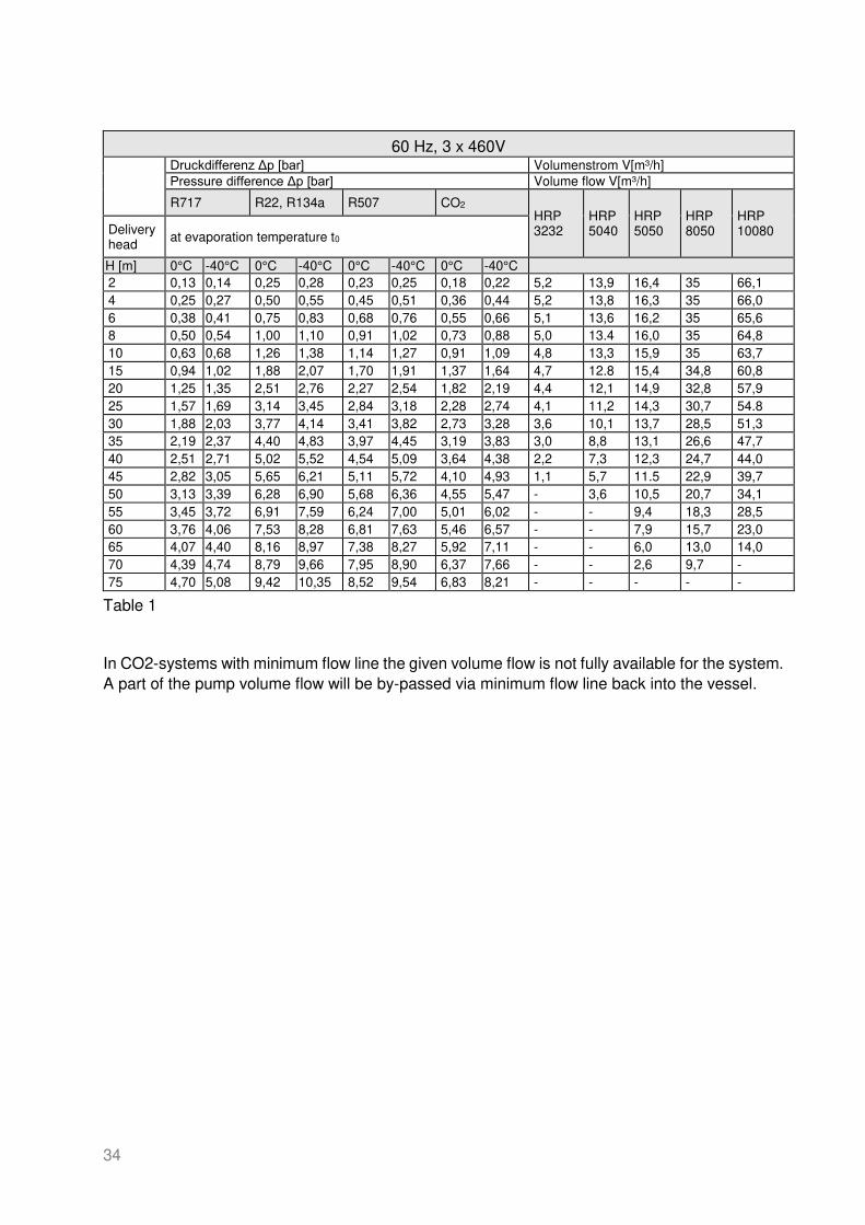
60 Hz, 3 x 460V
Druckdifferenz Δp [bar] Volumenstrom V[m³/h] Pressure difference Δp [bar] Volume flow V[m³/h]
R717 R22, R134a R507 CO2 HRP 3232
HRP 5040
HRP 5050
HRP 8050
HRP 10080 Delivery
head at evaporation temperature t0
H [m] 0°C -40°C 0°C -40°C 0°C -40°C 0°C -40°C 2 0,13 0,14 0,25 0,28 0,23 0,25 0,18 0,22 5,2 13,9 16,4 35 66,1 4 0,25 0,27 0,50 0,55 0,45 0,51 0,36 0,44 5,2 13,8 16,3 35 66,0 6 0,38 0,41 0,75 0,83 0,68 0,76 0,55 0,66 5,1 13,6 16,2 35 65,6 8 0,50 0,54 1,00 1,10 0,91 1,02 0,73 0,88 5,0 13.4 16,0 35 64,8 10 0,63 0,68 1,26 1,38 1,14 1,27 0,91 1,09 4,8 13,3 15,9 35 63,7 15 0,94 1,02 1,88 2,07 1,70 1,91 1,37 1,64 4,7 12.8 15,4 34,8 60,8 20 1,25 1,35 2,51 2,76 2,27 2,54 1,82 2,19 4,4 12,1 14,9 32,8 57,9 25 1,57 1,69 3,14 3,45 2,84 3,18 2,28 2,74 4,1 11,2 14,3 30,7 54.8 30 1,88 2,03 3,77 4,14 3,41 3,82 2,73 3,28 3,6 10,1 13,7 28,5 51,3 35 2,19 2,37 4,40 4,83 3,97 4,45 3,19 3,83 3,0 8,8 13,1 26,6 47,7 40 2,51 2,71 5,02 5,52 4,54 5,09 3,64 4,38 2,2 7,3 12,3 24,7 44,0 45 2,82 3,05 5,65 6,21 5,11 5,72 4,10 4,93 1,1 5,7 11.5 22,9 39,7 50 3,13 3,39 6,28 6,90 5,68 6,36 4,55 5,47 - 3,6 10,5 20,7 34,1 55 3,45 3,72 6,91 7,59 6,24 7,00 5,01 6,02 - - 9,4 18,3 28,5 60 3,76 4,06 7,53 8,28 6,81 7,63 5,46 6,57 - - 7,9 15,7 23,0 65 4,07 4,40 8,16 8,97 7,38 8,27 5,92 7,11 - - 6,0 13,0 14,0 70 4,39 4,74 8,79 9,66 7,95 8,90 6,37 7,66 - - 2,6 9,7 - 75 4,70 5,08 9,42 10,35 8,52 9,54 6,83 8,21 - - - - -
Table 1
In CO2-systems with minimum flow line the given volume flow is not fully available for the system. A part of the pump volume flow will be by-passed via minimum flow line back into the vessel.

35
5. APPLICATIONS
5.1 GENERAL
In industrial refrigeration systems pumps are used to deliver refrigerant to the evaporators. WITT hermetic refrigerant pumps are designed especially for this purpose. The principle of a pump re-circulation system is shown in fig. 4.
Fig. 4 principle of pump re-circulation system
WITT HRP refrigerant pumps differ from conventional centrifugal pump designs due to the fact that large volumes of entrained vapour (gas bubbles) do not completely stop delivery of the re-frigerant liquid.
Large volumes of gas occur in the pump suction when the evaporation temperature of the plant varies during the production cycle, particularly when starting the compressor (pull-down) and dur-ing the rapid loading or unloading of compressor steps of capacity.
Large amounts of gas bubbles in the pump suction line will cause the mass flow of liquid refriger-ant to be reduced.
Special attention has to be taken to ensure that the pump suction lines are generously sized.
It is important hermetic pumps are supplied with liquid refrigerant at all times. Long periods of cavita-tion must be avoided, as this will cause premature failure of the pump. It is important the installation instructions in chapter. 6 are correctly understood and followed.
When a minimum flow into the system can be guaranteed at all times, no by-pass lines are re-quired (see chapter 6)
OPERATIONAL LIMITATIONS
All HRP pumps are suitable for use at 50/60 Hz and all common refrigerants, e.g. NH3, CO2, R134a, R404a, R410, R507, etc.

36
HRP8050 requires, when operated with synthetic refrigerants (HFC, HFO), e.g. R134a, R404A, R410, R507, a larger motor. Therefore these re-frigerants must be specified when ordering!
A horizontal separator is recommended: this gives greater surface area for the settlement of any oil and stable
suction head conditions.
5.2 DETERMINATION OF THE DELIVERY HEAD
The required delivery head is the resistance the pump needs to overcome to supply the evapora-tor with the high-est pressure loss with sufficient liquid refrigerant (in most cases this will be the furthest distant evaporator).
The delivery head is depending from:
• Height difference between pumps and evaporators • Resistance of pipe work and evaporators • Pressure losses of valves and fittings in the delivery line • Density of the refrigerant
The max. allowable delivery head should never be exceeded, because otherwise the pump is operated outside the permitted range and will see internal damages (see chap. 6.5)
5.3 DETERMINATION OF THE REQUIRED FLOW
The evaporators have to be supplied with sufficient liquid refrigerant, so that
• The surface of the evaporators is fully used • Supply to several evaporators with ifferent duties is as even as possible.
The re-circulation rate is calculated as follows:
Re − circulation rate = mass flow pumpevaporated refrigerant = 𝐌pump𝐌Q0
A re-circulation factor of 4 means that 3 parts refrigerant are returned as liquid and 1 part is evaporated.
The re-circulation rate depends on the type of evaporator equipment and operation conditions.
The larger the duty, loading rate, the greater the recommended re-circulation factor.

37
RE-CIRCULATION RATES AND PUMP CAPACITY
Recirculation factor Recirculation flow in m³/hr per 100 kW*
Refrigerant CO2 NH3 R22 CO2 NH3 R22
Air Cooler 1,2 – 2,0 3 - 4 2 - 3 1,4 – 2,4 1,3 – 1,8 2,8 – 4,3
Plate Freezer 5 - 10 7 - 10 5 - 10 6 - 12 3 – 4,5 6,5 - 13
Liquid Chiller 1,2 – 1,5 1,2 – 1,5 1,2 – 1,5 1,4 – 1,6 0,6 1,7
*) including re-circulation rate
Table 2
5.4 ADAPTATION TO PLANT REQUIREMENTS
Fig. 5 shows different plant operating conditions. The delivery head H is shown in relation to the required plant capacity Q.
Performance curve characteristics of the refrigerant pump are shown in fig 5A. The different points W mark the varying plant conditions that may occur during operation.
If the required liquid flow does not correspond with the available pump capacity then the liquid flow to the sys-tem can be adjusted as follows:
pump capacity too large:
• switch off a pump • open a liquid bypass valve, fig. 5B • speed control of the pump, fig 5C
pump capacity too small:
• switch on an extra pump, fig 5D • install a larger pump
Fig. 5, A-D
V1 +V2 ≠ 2 x V1

38
5.5 USE OF FREQUENCY CONVERTERS
When using frequency converters the frequency should never be less than 40 Hz to ensure the minimum required refrigerant flow is maintained.
The start/stop ramp should be set steep enough, so the check valve on the discharge valve can open fast enough. (From experience the ramp should be set at 1 s).
Since a differential set overflow valve cannot be used for the varying pressure differences over the pump, it must be ensured in a different way that there is always sufficient flow through the pump.
If operating against closed evaporators is possible, a permanent open bypass line is required.
Further information regarding recommended control systems can be found in the annex at the end.

39
6. INSTALLATION INSTRUCTIONS
To ensure trouble free operation some basic rules need to be applied to the installation of the HRP pumps.
6.1 PUMP ARRANGEMENT
The installation must be designed as compact as possible below the separator or low-pressure receiver. Allow sufficient access space around the pumps for removing or replacing the pump, servicing valves, setting pressure difference control, inspection and cleaning the conical strainer. Also allow space for normal frost/ice accumulation around the pump.
Vertical distance between bottom of the separator to the pump centre shall be at least 1 m. Greater distance will make the pump less sensitive to system pressure fluctuations.
Particularly with CO2 applications of temperatures warmer than –10°C a minimum suction head of 1,5 m is required!
The downleg should be positioned in such a way that gas entrainment from the return line is minimised (e.g. installation of the return line with an elbow in a safe distance).
The suspended mounting of the pumps with threaded bars of at least 180 mm length is recommended. HRP 5040, HRP5050, HRP8050 and HRP10080 should be aligned horizontally, wheres the HRP 3232.
Please consider that
• A condensate trip tray can easily be placed and cleaned. • The conical suction line filter can be cleaned easily. • Stress in the piping system is avoided.
6.2 PUMP CONNECTION
The top connection of the suction line to the separator can be made with a down pipe with vortex breaker.
The vortext breaker shall consist of crossed plates with a baffle plate on top to avoid any vortexing. Vortex breakers are available from TH. WITT.
Above the baffle plate of the vortex breaker there should be at least 15mm refrigerant level (in CO2 systems a minimum coverage of 50mm is required).
When using non-soluble oils in ammonia systems special attention must be taken that any oil, which may settle, does not drain into the duty or stand-by pump.
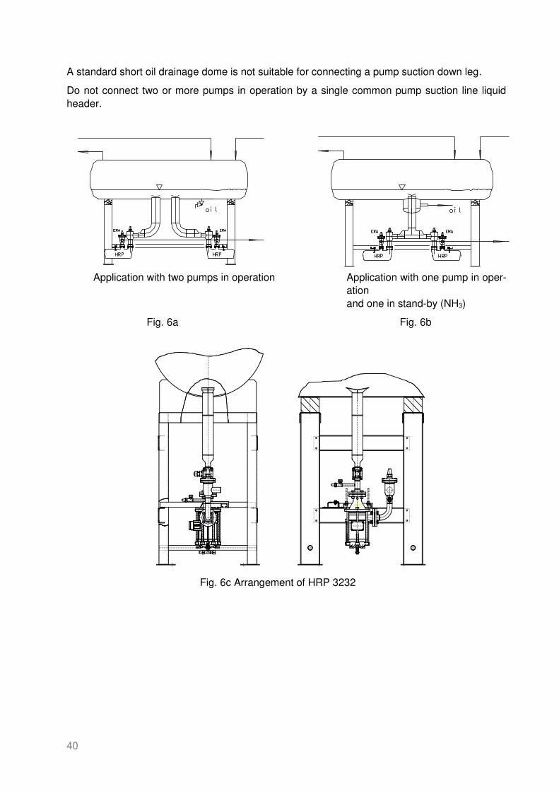
Therefore it is recommended that the suction down leg protrudes into the surge drum by 30 - 40 mm, depending on the vessel diameter (see fig. 6a).
40
A standard short oil drainage dome is not suitable for connecting a pump suction down leg.
Do not connect two or more pumps in operation by a single common pump suction line liquid header.
Application with two pumps in operation Application with one pump in oper-ation and one in stand-by (NH3)
Fig. 6a Fig. 6b
Fig. 6c Arrangement of HRP 3232

41
6.3 DOWNLEG DESIGN
The pump shall be connected vertically with the separator. To prevent interference between pumps it is advised that each pump be connected individually to the separator, see fig. 6a.
When a stand-by pump is planned, an installation according fig. 6b is recommended.
To avoid any vortexing the downleg here again protrudes into the separator.
An oil drainage dome around the suction line, as shown in fig. 6b, can be favourable.
Consideration shall be given to the fact that the suction line must be installed directly to the pump, avoiding addi-tional elbows or horizontal run.
Any gas accumulation in the suction line and particularly in valves attached to the pump must be avoided. Gas bubbles should be able to flow back to the separator unhindered, counter to the liquid flow, especially when the pump is not in operation.
When there is no separate vent line installed it is important the pumps can vent to the suction side, which means the suction downleg must be open during stand-still.
Shut off valves in the suction line shall be sized generously and without reducers to enable de-gassing. Installation of full-bore ball valves are recommended. Straight through valves must be installed with stem in horizontal position; ball valves should not have a reduced bore on the pump side connection.
Until now we have not recommend filters in the liquid downleg as these create additional pressure loss. How-ever, positive experience has proven that the use of filters in systems with high levels of contamination (i.e. due to installation of non-shot blasted pipes and vessels) is better than contamination of the pump.
Filters with a mesh of 500 µm (e.g. Parker T5F-SS, AWP-SS, RFF FA or Danfoss FIA) should be installed in systems with a potential for contamination.
Upmost care should be taken to clean the filters as often as possible during the first weeks of operation, until they remain clean.
Since external filters have a larger filter surface and can be cleaned more easily, we recommend you keep these in place and remove the conical filter in the pump inlet to avoid two filters causing excessive pressure drop. A regu-lar check (1 – 2 per year) should be included in the maintenance routine.
To be sure the pump will operate even at a low-pressure difference resulting in maximum capacity, the diameter of the downleg to the pump must be executed as mentioned in the table below as a minimum!

42
Required diameter of the downleg to the pumps
HRP 3232 HRP 5040 HRP 5050 HRP 8050 HRP 10080
50 Hz DN 80 DN 100 DN 125 DN 150 DN 250
60 Hz 3” 4“ / 5“ 5“ 6“ / 8“ 10“
Table 3
Under no circumstances shall the maximum velocity of ammonia systems in the downleg exceed 0,3 m/s!
Systems operating at 60Hz have to select a DN125 (5“) suction line when the delivery head is below 25 m for HRP5040, whereas the HRP8050 requires below 40 m a DN200 (8”) suction line diameter.
The conical suction filter that comes with the pump must be fitted at all times to protect the pump from any contamination!
6.4 PUMP DISCHARGE LINE
The design of the discharge line is less critical to the system operation. A liquid velocity of 1.5 m/s is normally recommended.
A non-return valve (this is usually a combined stop/check valve type ERA) in the discharge line is required when a backwards flow from the discharge to the suction side is possible. This may be the case, when:
• several pumps are connected to one discharge manifold • the static head to the coolers is high.
A non-return valve should be mounted as close as possible to the discharge flange. If a larger distance is required, an additional vent line should be installed to prevent a possible gas blockage.
VENT LINE
If the suction line needs to be closed during stand-still or the check valve is installed in a distance from the pump an additional vent line is required.
A minimum flow line is always recommended in CO2 sytstems, which also vents the pump during stand-still.
To avoid backflow of refrigerant during stand-still it is important that each pump is individually connected with a separate vent line immediately in front of the check valve on the delivery side to the top of the surge drum.
The stop valve after the orifice shall be DN20 (3/4”) respective DN25 (1”) if installed in the part of the vent line that can contain liquid.

43
If the valve is installed in the gas part of the vent line, immediately in front of the connection point to the CO2 vessel a smaller valve is sufficient, e.g. DN10 (0.4”). The stop valve must be locked in an open position and marked “do not close during normal operation”.
In application with a non-return valve or solenoid valve liquid may be trapped. When this liquid is warmed up, the pressure increases rapidly to an unacceptable value and the piping may fracture.
Adequate precautions must be taken by the installer to prevent any liquid from becoming trapped.
PIPING FROM THE CONDENSER IN CO2 SYSTEMS
From experience it has proven good practice to enter with the line from the condenser into the surge drum below the liquid level and as such minimize the surface available for condensation in the vessel.
6.5 PROTECTION OF THE PUMP
REQUIRED MINIMUM FLOW
To provide the pumps with sufficient liquid refrigerant for lubrication and cooling it is important to maintain a minimum flow per following table through the pump at all times. This can be achieved when the design or the control system ensures there is always sufficient flow to the evaporators.
When the control system allows that a major part or all evaporators can be closed, a by-pass line is required to protect the pump against too high pressure (see chap. 6.5.2) and ensure a minimum flow.
Required minimum flow
V @ 50 Hz V @60 Hz
m³/h gal/min m³/h gal/min
HRP3232 0,6 2.6 0,7 3.1
HRP5040 1,2 5.3 1,5 6.6
HRP5050 3,0 13,2 3,5 15,4
HRP8050 5,0 22 5,5 24
HRP10080 8,0 35 9,6 42

44
SAFEGUARDING AGAINST TOO HIGH PRESSURE
Operating refrigerant pumps against too high pressure (e.g. against partially or fully closed throttled condition) is not allowed and will damage the refrigerant pump!
A by-pass valve (adjustable) has proven good practice to safeguard the pump against too high pressure, with the exception of CO2 systems.
To set the by-pass valve select the pressure difference across the pump according table 1 for the following de-livery head. (take into account the pressure losses in the pipework to the by-pass valve)
40Hz 45Hz 50Hz 55Hz 60Hz HRP 10080 30 m 38 m 45 m 52 m 60 m HRP 8050 30 m 38 m 45 m 52 m 60 m HRP 5050 28 m 36 m 45 m 52 m 60 m HRP 5040 16 m 22 m 30 m 36 m 45 m HRP 3232 13 m 18 m 25 m 31 m 37 m
The following tables give the settings of a differential pressure operated overflow valve (e.g. A4AL or CVP-PP) for several refrigerants at evaporation temperatures of 0°C (32°F), -10°C (14°F) and -40°C (-40°F) and 50Hz respective 60 Hz.
The settings are also mentioned in our selection program.
50 Hz, 3 x 400V
Set point Δp Evap. Temp. NH3 R404A/R507A R134a
°C °F [bar] [psi] [bar] [psi] [bar] [psi]
HRP3232 0 32 1,5 22 2,8 41 3,1 22
-10 14 1,6 23 2,9 42 3,2 47
-40 -40 1,7 24 3,1 45 3,4 50
HRP5040 0 32 1,8 27 3,4 49 3,8 55
-10 14 1,9 28 3,4 51 3,9 56
-40 -40 2,0 29 3,7 54 4,1 60
HRP5050 HRP8050
HRP10080
0 32 2,8 41 5,1 73 5,7 82
-10 14 2,8 42 5,2 76 5,8 85
-40 -40 3,0 44 5,6 82 6,2 90

45
60 Hz, 3 x 460V
Set point Δp Evap. Temp. NH3 R404A/R507A R134a
°C °F [bar] [psi] [bar] [psi] [bar] [psi]
HRP3232 0 32 2,5 36 4,5 65 5,0 73
-10 14 2,5 37 4,6 68 5,2 76
-40 -40 2,7 39 5,0 73 5,5 80
HRP5040 0 32 2,8 40 5,1 73 5,7 83
-10 14 2,8 42 5,2 76 5,8 85
-40 -40 3,0 44 5,6 82 6,2 90
HRP5050 HRP8050
HRP10080
0 32 3,7 54 6,7 98 7,6 110
-10 14 3,8 56 7,0 102 7,8 114
-40 -40 4,0 59 7,5 109 8,3 120
The adjustable by-pass valve shall be sized according to the following values: DN 20 for the HRP 3232 and HRP5040, DN 25 for the HRP 5050 and HRP 8050 and DN32 for HRP10080.
Experience of various CO2 installations revealed that pressure regulated overflow valves do not work reliable. When it is not certain the required minimum flow per chap. 6.5.1 is always available, a MINIMUM FLOW LINE with permanent open orifice per following table is required
It is recommended each pump receives it’s individual minimum flow line. This will also serve as vent line during stand-still.

46
DIMENSIONS OF THE MINIMUM FLOW LINE IN CO2 SYSTEMS
50 HZ
D orifice mm* inch** part mm* inch** HRP3232 27,3 0,96 4419.020104 4,0 0,16 HRP 5050 27,3 0,96 4419.020103 7,0 0,28 HRP 8050 27,3 0,96 4419.020101 9,8 0,38 HRP10080 27,3 1,28 4419.020102 12,0 0,47
60 HZ
D orifice mm* inch** part mm* inch** HRP3232 27,3 0,96 4419.020114 4,0 0,16 HRP 5050 27,3 0,96 4419.020113 7,0 0,28 HRP 8050 27,3 0,96 4419.020111 9,5 0,38 HRP10080 27,3 1,28 4419.020112 12,5 0,47
* mm values for DIN pipes /
** inch values reference schedule 80 pipe
*** Article orifice consisting of: flanges, orifice, gasket, bolts and nuts

47
MINIMUM STAND-STILL PERIOD
A restart of the pump is only allowed when the pump has been able to vent correctly. The mini-mum stand-still time to achieve correct venting is determined by the type of refrigerant and the evaporating temperature. For ammonia applications the pump will normally require 3 to 5 min. For CO2 systems this period should be increased to 15 min, or for warmer CO2 (>-10°C) to at least 20 min. With a minimum flow line the time to vent the pump is reduced to about 5 min.
When the downleg is closed during stand-still it takes longer (possibly more than 20 min) to vent all gas through the pump internal vent hole, once the suction valve has been fully opened (nor-mally until frost is formed in the motor area). If a waiting period is to be avoided, a small vent line is required (see chap. 6.4).
MINIMUM OPERATION TIME
The highest heat impact for the pump takes place when the starting torque of the motor consumes the highest current. Therefore a minimum operation time of 1 to 2 minutes (in CO2 systems 5 minutes) should be pro-grammed to allow for stable operating conditions.
DRY-RUN PROTECTION
If a minimum level cut out switch is mounted on the separator, it shall be used to switch the pump off in case of a lack of refrigerant (dry run protection).
PRESSSURE DIFFERENTIAL SWITCH
A PRESSURE DIFFERENTIAL SWITCH - with time delay during start up - shall be used when there is insufficient discharge pressure.
The delay should be set at 30 to 60 s, which means if the pump was not able to build up pressure (e.g. 0,3 – 0,5 bar) within 30 s, the pump will be stopped
This procedure can be repeated a maximum of four times. Then a malfunction message should be submitted and the pump switched off. After that a restart should only be made after investiga-tion of the cause of failure and ac-knowledging the fault indicator.
The pressure differential switch does not protect the pump against too high pressure run-ning (dead heading)!
FLOW SWITCH
A flow switch must be installed, when a bypass valve is not fitted in the refrigerant circuit. It is known when the bypass valve is not fitted, the pump is capable of producing a differential pressure without volume flow ,and has not been stopped by the differential pressure switch. The flow switch control in the pump discharge shall stop the flow as the flow drops below 0,2 m/s.
See WITT information sheet W 4652-0.01

48
6.6 ELECTRICAL INFORMATION
The following equipment must be provided in the electric control circuit of the motor:
OVERLOAD PROTECTION
An overload protection switch shall protect the pump against too high current (amps) consump-tion. Maximum setting must be less than max. allowable current Imax for the selected refrigerant. See chapter 4.2.
TEMPERATURE CUT OUT
All HRP pump models are, since 12/2000, equipped with PTC resistors in the motor windings, which are con-nected at clamp terminals #1 and #2 with U ≤ 2,5 V.
The required PTC motor control relay, e.g. INT 69 V, can be supplied by WITT.
The clamp terminals #1 and #2 are protected by a picofuse 62 mA (art.no 2591.000101) and an additional con-nection MBK “0” (art.no 2591.000201). There is a spare picofuse 62 mA inside the cover of the terminal box (see below).
The PTC-resistor interrupts the control voltage to the motor relay when the motor temperature exceeds a critical value. Automatic restart after cooling down the pump must be restricted. Start up should only be allowed after investigation of the cause of the motor trip and inspection of the refrigeration system. The minimum stand-still period should be considered.
This PTC resistor must be connected, otherwise the warranty is void!
Until 12/2000 the thermal protection of HRP 5040 and HRP 8050 was obtained using a thermoswitch (klixon), which was connected with 220V (see wiring information, fig. 7).
When the pump is stopped by a safety device restart is only permitted after investigation of the cause of stoppage.
Prior to restarting the pump it must be ensured the pump is properly cooled down/vented, so about evaporation temperature is reached. Particularly after the pump was stopped by the temperature cut-out is may take up to 60 min!
Picofuse
62 mA

49
HAND SWITCH
It is recommended the control panel incorporates a Hand–0ff-Auto switch for use during com-missioning and maintenance operations.
It is important to take care that during manual operation of the pump all safety devices in the circuit are connected and in good working condition.
NIL VOLTAGE BEARING CONDITION TEST
For the horizontal pump models it is possible to detect bearing wear during pump stand still. The external end of the sensor wire under the cap (77) can be used to measure the electrical re-sistance.
When a closed circuit with the pump housing is observed, the bearings are worn and the pump must be sent to the supplier for repair.

50
MotorschutzQ1
S1
H-0-ASchalter
manual-autom.
switch
Hand-freigabe
safety-switch for
manual operating
K1x K2x
K6
K7
21
2211
1214
K1M
A 1
A 2
K2T
A 1 A 1 A 1 A 1 A 1
A 2 A 2 A 2 A 2 A 2
Autom.Kälteanforderung
request
cooling
K413
14
K433
34
K2T15
18
K3x
Störungquittieren
reset
K3T15
18
K613
14
K3x
Störungquittieren
reset
L
N 1 2
B1 B2 11
1214
Thermistor - AuslösegerätThermistor motor protection unit
K7
B8
1
2
KaltleiterPTC-thermistor
N
L1
K3T K4 K5 K6
NH3 - Pumpe "ein"NH3 - Pump "on"
Impuls/Pauseimpulse/break
15/30s
I/P-Überwachungi/b-supervise
Zeit/time ca. 3min.
Inpuls/Pauseimpulse/break
StörungKaltleiter
fault
PTC-thermistor
StörungDiff.Druck
fault
pr.diff.switch
KaltleiterAuslösegerät
PTC-thermistor motor
protection unit
KaltleiterPTC-thermistor
95(13)
96(14)Overload protection
Datum : 01.12.2000
Zeichn.Nr.:3-16128.0342.001.007s
Blatt : 1
HRP 3232, HRP 5050, HRP 10080und/and seit/since 01.12.2000
HRP 5040 und 8050
Typ / typeHRP3232
seit / since01.12.2000HRP5040HRP8050
Informationszeichnungpresentation of information
Diese Zeichnung zeigt die , von der Fa. Witt em pfohlene,Steuerung der Kältem itte lpum pen Typ HRP
recommended wiring diagram, refrigerant pump type HRP
62
1 8
7
1413 15 16
Strömungswächter
flow indicator MS96-12-R...
1 2 3 4
S e n s o r
xx xx xx xx
A1
.1
.2
.3
.4
xx
xx
xx
xx
xx
xx
xx
xx
B1
xx xx
Steuerung m it Ström ungsw ächter / control with flow indicator
Fig. 7a Recommended electrical wiring diagram with flow switch

51
dP
Motorschutz
Q1
Diff.DruckSchalter
S2
S1
H-0-ASchalter
manual-autom.switch
Hand-freigabe
safety-switch for
manual operating
K1x K2x
K6
K7
21
22
11
1214
K1M
A 1
A 2
K2T
A 1 A 1 A 1 A 1 A 1
A 2 A 2 A 2 A 2 A 2
Autom.Kälteanforderung
request
cooling
K413
14
K433
34
K2T15
18
K3x
Störungquittieren
reset
K3T15
18
K613
14
K3x
Störungquittieren
reset
L
N 1 2
B1 B2 11
1214
Thermistor - AuslösegerätThermistor motor protection unit
K7
B8
1
2
KaltleiterPTC-thermistor
N
L1
K3T K4 K5 K6
NH3 - Pumpe "ein"NH3 - Pump "on"
Impuls/Pauseimpulse/break
15/30s
I/P-Überwachungi/b-supervise
Zeit/time ca. 3min.
Inpuls/Pauseimpulse/break
StörungKaltleiter
fault
PTC-thermistor
StörungDiff.Druck
fault
pr.diff.switch
Kaltleiter-Auslösegerät
PTC-thermistor
motor protection unit
KaltleiterPTC-thermistor
95(13)
96(14)
Overload protection
Pressuredifferential
switch
Datum : 01.12.2000
Zeichn.Nr.:3-16128.0342.001.007-
Blatt : 1
HRP 3232, HRP 5050, HRP 10080und/and seit/since 01.12.2000
HRP 5040 und 8050
Typ / type
HRP3232seit / since01.12.2000HRP5040HRP8050
Informationszeichnungpresentation of information
Diese Zeichnung zeigt die , von der Fa. Witt em pfohlene,Steuerung der Kältem itte lpum pen Typ HRP.
recommended wiring diagram, refrigerant pump type HRP
xx
xx xx
xx
.1
.2
.3
.4
xx
xx
xx
xx
xx
xx xx
xx xx
Steuerung m it Differenzdruckschalter / control with pressure differentia l switch
Fig. 7b Recommended electrical wiring diagram with differential pressure switch

52
Fig. 8A Fig. 8B
Wiring information inside the terminal box Old execution of HRP 8050 and HRP 5040 until 12/2000
The correct direction of rotation, indicated by the cast arrow on the pump housing, is obtained if the electric con-nections are made as detailed in the terminal box electric wiring diagram, fig. 8, with the phase sequence rotating clockwise. The direction of the phase sequence can be measured with specific measuring equipment. The electrical connection information is also available on the label inside the cover of the terminal box; see fig. 8.
The terminal box has two sizes of cable sockets. All cable and electrical connections including the terminal box have to be made to IP 54.
Fig. 9 a Wrong connection Fig.9 b Correct connection with loop in electrical cable
It is important that all electrical cables are connected with a loop to the terminal box (see fig 9 b.)
By using a loop any condensate that may run along the cable is prevented from running into the terminal box.
The terminal box must be sealed at all times, to prevent dirt and moisture to come in; also touching of the connections has to be avoided.
The length of the loop shall be of sufficient length to enable the tilting and moving of the pump during inspection and replacement of the conical strainer in the pump suction connection.
70°C U V W 1 2 PE L1 L2 L3 PE rechtes Drehfeld Thermokontakt 2A ac clockwise phase sequence thermostatic bimetal
+
3x U V W 1 2 PE L1 L2 L3 PE rechtes Drehfeld Thermistor clockwise phase sequence U 2,5V

53
7. TRANSPORT AND STORAGE
All connections are protected with yellow plastic caps to prevent any dirt or moisture contami-nates the pump.
Storage shall be dry and protected from any dirt or debris.
Please lift the pumps according to the following photos.
The terminal box must not be used when lifting the pump!

54
8. INSTALLATION AND APPLICATION
All of the following specified work must be carried out by knowledgeable and trained personnel experi-enced in installation and service of refrigeration systems!
8.1 PREPARING THE PUMP FOR INSTALLATION
Before the pump is installed the following functions should be carried out:
• unpack the pump and check for possible damage during shipping and the correct scope of equipment supplied. Pay special attention to the electric terminal box and the con-nection of the sensor wire (77). In case of any damages inform your supplier immedia-tely.
• Excepts sensore wire cap (78,) remove all plastic caps or other sealings immediately prior to (and not before) installation of the pump.
• check that the conical suction strainer has been supplied and that the gaskets are on both sides of the suction strainer mounting ring.
• the gaskets must be clean and lightly covered with oil. • Make sure all equipment connections are clear of plastic caps and rags. • the piping system is to be clean and free of any moisture.
The HRP-pumps have undergone a short mechanical test run at ambient temperature with refrigerant machine oil, FUCHS Reniso synth 68, in the factory. If the pump is to be used in systems where contamination with this oil is not allowed, i.e. in cases with ester oil in the system, the residual oil must be removed and the pump cleaned by use of solvents.
8.2 MOUNTING INSTRUCTIONS
In order to drain the refrigerant pump for mainte-nance and cleaning of the suction strainer without completely dismantling it, sufficiently long threaded rods are required for suspended installation.
It is recommended to make them at least 180 mm long in order to ensure sufficient space for replacing the pointed screen.
A clearance of at least 95 mm must be provided be-low the refrigerant pump to allow the refrigerant pump to be lowered and an EA10 valve for oil drain-age to be fitted if necessary.

55
When HRP pumps are foot-mounted, the pump must be installed stress free to the base frame and the piping system. Special attention must be paid to the expected pipe contraction at low temperatures.
For inspection and cleaning of the suction strainer it is sufficient to remove the screws of the flanges, loosen the nuts of the threaded rods and lower the refrigerant pump to the suction side.
It is important vertical pumps HRP3232 are aligned vertically, wheras the horizontal pumps HRP5040 to HRP10080 are horizontally aligned.
For pump arrangement see for instance fig. 6a, 6b and 6c.
Flange Alignment
Make sure the pump connection flange (grooves and tongues) are properly aligned. Do not use the flange bolts to align or "stretch" the pipe. Using flange bolts to pill together a too large gap will cause undue stress or distort the pump or the flange.
Do not use the mounting bolts to pull down the pump on to the frame work, the cast iron mounting footpads can fracture. Prior to mounting the pump it should be aligned with holes, using chims and if necessary use longer threaded bars with counter nuts.
The required torque to tighten the flange screws properly are given in the following table.
Nut size Required torque Suction flange of Delivery flange of
M12 85 Nm
HRP5040
HRP5050
HRP5040
HRP5050
HRP8050
M16 210 Nm
HRP3232
HRP8050
HRP10080
HRP3232
HRP10080
Table 4

56
8.3 PRIOR TO COMMISSIONING
• the refrigeration system must be pressure tested, vacuum tested and be fully charged with refrigerant.
• the suction- and discharge valves must be fully open • the valves of the pressure differential control, if fitted, must be fully open • the pressure differential switch, if fitted, must be set at a difference of at least 20 kPa
above the system static height. (static height means "liquid column + pressure differ-ence between cooler inlet and separator")
• a sufficient volume of refrigerant must be present in the separator or low pressure re-ceiver for a minimum running time of approxately 2-3 minutes.
• the electrical control system including all safety controls must be pre-tested prior to starting the pump.
• Check the wiring for the correct rotation of the motor.
8.4 COMMISSIONING PROCEDURE
• check and record the pressures in the system • if the pressure difference is smaller than expected, the pump may be rotating in the
wrong direction. Check proper rotation by measuring phase sequence. If it is neces-sary, switch off electrical system, change over two connecting cables and test pressure difference again.
• Close the discharge valve until the pressure difference reaches a maximum value as per table 1 and set the flow switch accordingly.
• If you hear unusual, or unfamiliar sounds from the pump, switch off the pump immedi-ately and investigate the cause.
When the pump operates normally, check after 2 hours, after 8 hours and later the pressure difference and note the measured values. After a period of trouble free oper-ation (1 to 2 weeks) you should inspect the conical filter for dirt and contamination. Depending on the degree of contamination the conical filter should be regularly inspected and cleaned at planned intervals.
8.5 DURING NORMAL OPERATION
During normal operation the pump does not require specific maintenance, there is no need to refill or to change the oil.
It is strongly recommended that the following items are checked frequently:
• check the conical suction filter for contamination • check the pumpre-circulation pipework for oil contamination • check the pressure differential of the pump • check the bearing wear • listen to the running sound of the pump. Crackling noise indicates oil contamination • once a year, or as dictated by the classification rules, the pump operation, settings and
all safety provisions should be checked. • The date, time and results of each inspection should be recorded together with the
serial number.

57
8.6 PUMP STANDSTILL (STAND-BY)
During periods of pump standstill, only one valve may be closed, preferably the suction valve. When the suction and discharge valves are closed at the same time, trapping cold liquid in the pump, the pressure will increase rapidly, as the liquid warms up, to an unacceptable high value. This increase in pressure can very quickly damage the pump.
If there is oil contamination during standstill of the pump, the oil must be drained from the pump before restarting the pump; otherwise a malfunction may occur which may lead to the failure of the pump.
58
9. SERVICE AND MAINTENANCE
9.1 REMOVING A PUMP
Follow all national and local safety requirements when removing the pump. Particular care must be taken of the following:
• Check the plant room layout and exit doors so you can evacuate the area quickly in case of an emergency.
• Seek assistance to handle and remove the pumps. • Wear the correct protective safety clothing, as minimum use a safety goggles and
gloves, in case of NH3 have a safety gas mask within easy reach.
Isolate the pump by switching off and locking off the electrical supply and the electrical controls. Make sure reconnection is not possible.
A label should be fixed to control panel to indicate pumps are switched off and are being worked on.
Note the sequence of electrical connections and disconnect the wiring.
A trained engineer or suitable qualified electrician in accordance with electrical engineering regulations should carry out any work on electrical equipment or controls.
Before moving or tilting the pump e.g. to access or to clean the conical suction filter, the refrig-erant must be dis-charged. It is recommended that the refrigerant is purged to the dry gas side of the surge drum via the pressure gauge valve at the base of the discharge valce. Hot water may be used on the outside of the pump to accelerate the boiling off of the liquid refrigerant.
Never use naked flame or open fire to warm up the pump.
When there is no liquid refrigerant left in the pump, carefully open the slotted screw plug on the suction housing (58) by ¼ turn to depressurise the pump. When there is no residual pres-sure inside the pump the flange bolts can be carefully unscrewed. Be aware of any trapped liquid or leaking valves seats.
9.2 SHIPPING OF THE PUMP
When a pump has to be returned to the supplier or the factory be sure the pump is free of refrigerant, dirt and oil. The risk of damages to goods or the environment by leaking oil during transport is at the senders risk.
When returning the pump it is important that full information is provided stating the reason and cause of failure.
Therefore, please fill out the pump checklist, available on our website, as much as possible.
Always return the conical suction filter, in actual conditionas found when the pump was opened, with the pump.
Please see chapter 7 for proper lifting of the pump.
9.3 GENERAL ADVICE
COMPRESSOR OIL IN THE PUMP
When too much oil flows into the pump from the separator, the pump will not operate properly or may be damaged.

59
Oil prevents sufficient cooling of the bearings resulting in an unacceptable overheating of the pump. Only the built in thermistor provides adequate safety.
Oil can be drained through a WITT EA 10 GÜ/GB stop valve which can be installed in place of the lower 1/4"-srew plug in the suction or discharge chamber.
Prior to installing the EA 10 GÜ/GB you have to make sure that the metall gasket 38 (see sectional drawing, fig. 3) has been removed. The counternut of the EA 10 GÜ/GB needs to be screwed down entirely to mount the valve. When the valve is screwed in you fix the EA GÜ/GB with the counter nut in the chosen position.
When the oil is to be drained while the pump housing is still under pressure, a quick closing action valve must be used in addition to the drain valve. Oil from the discharge can only be removed from the pump trough the drain plug on the discharge side. At low temperatures when oil flow is slow the pump must be warmed up on the outside with warm water to lower the viscosity of the oil making it flow more easily. The oil return system from the surge drum should be checked or modified to prevent further oil con-tamination of the pump.
DAMAGED ROTOR CAN
You cannot automatically detect whether the rotor can is damaged or is leaking since the stator housing is de-signed at the same compressive strength. To find out whether refrigerant has penetrated into the stator housing loosen carefully the 1/4" screw plug on the motor cover (09).
Always wear personal protective safety clothes, especially safety glasses!
Use a leak detector or if NH3 was used you will simply smell whether refrigerant is present in the transformer oil.
PUMP INTERCHANGEABILITY
The inlet and outlet connection flanges of the HRP 5040, HRP 5050, HRP 8050 and HRP 10080 pumps are of the same sizes and diameters as FAS-flanges. All flanges are of a square design and have four (4) bolt holes.
The inlet and outlet connecting flanges of the HRP 3232 up to 40 bar are round type, EN 1092-1/11, C/DN32/PN40 (former DIN 2635/2512).
All other flanges are specially made and are therefore always delivered with counter flanges.
If you want to replace WITT GP pump models with HRP pump models please contact your supplier for further in-formation.
9.4 REPARING A PUMP
It is not recommended you open and repair the pump. Preferably send the pump for repairing to your supplier or to the factory, if required request a replacement pump.
Repairs should only use factory supplied assemblies and be fitted by specially WITT trained personnel.
During the training a repair manual will be supplied by the manufacturer.
9.5 WARNINGS
WITT-HRP-pumps are of the canned type. All rotating parts, including bearings and motor rotor are in direct contact with the refrigerant.
Any unusual running conditions other than stable operation will have an influence on moving parts particularly the bearings. Dirt, oil and large pressure fluctuations may shorten the lifetime.

60
WITT HRP pumps are for refrigeration systems only. Read these instructions completely before selecting, using, or servicing these pumps. Only knowledgeable, trained refrigeration mechanics should install, operate, or service these pumps.
Stated temperature and pressure limits should not be exceeded.
Special attention must be paid to the national rules concerning the available materials.
Pump should not be removed unless system has been evacuated to zero pressure.
All local rules to refrigeration systems, and electric control and installation systems must complied with.

61
10. TROUBLE SHOOTING
No. symptom Possible causes
1 pump makes
scratching noise
- noise comes from outside - foreign material in pump - operation against a too high pressure – check the setting of your overflow
valve (or whether there is sufficient flow to the evaporators) - in CO2 systems check whether the minimum flow line is fully open - gas in the pump (e.g. level below minimum level in the surge drum, conical
filter is blocked, too fast reduction of the evaporating temperature) - impellers or intermediate pieces worn out - bearings worn out - rotor in contact with can
2 capacity too low
(valves on pump open)
- direction of rotation wrong - stop valves behind the pumps closed - too much gas in liquid (e.g. liquid level in separator too low, conical filter
blocked, pump operates against a too high pressure) - valves on cooler closed - regulating valve not opened far enough - overflow valve pressure set too low - contamination is blocking the piping system - non return valve of an other pump leakes - dirt in the coolers - power supply not right, working on only 2 phases - impellers worn out - oil in pump at low temperature - wrong pump selection (not sufficient delivery head )
3 switched off on pres-sure difference con-trol
- see number 2 - set value of pressure control not right - hand control valves in system opened too much - too quick start up or capacity steps of compressor(s) - too quick switch off of big capacities
switched off on
flow switch
- see number 2 - set value of flow switch not right - suction side or discharge side closed - too quick start up or capacity steps of compressor(s) - too quick switch off of big capacities
5 switched off by too high temperature
- Too much oil in the pump - Pump too warm (e.g. not sufficient cool down time right after installation,
switching too much on/off, no minimum still-stand period (chap. 6.5)) - bearing filter (92) blocked
6 switched off by too
high power consump-tion
- Too much viscous oil (at low temperatures) - Contamination with dirt, foreign material - Internal damages
7 life time of bearings
too short
- too much gas in the pump, see above points - reverse flow through the pump (e.g. no or leaking check valve behind the
pump, incorrect installed vent- or minimum flow lines, see chapter 6.4) - too much dirt in system
8 Motor protection/fuses trip the pump
- Moisture in the terminal box: check the connections and seal the terminal box
- Pump is blocked (see above)

62
ANNEX
Recommendations for the control of HRP pumps
Steuerung 2 + 3: Betriebszustand (pro Pumpe)Control 2 + 3: operation (for each pump)
Pumpe ausschaltenStop pump
Ja / Yes
Pumpe läuft / pump in operation
O.K.
ΔP zu niedrig / too low20 Sec
Neustart der PumpeRe-start pump
20 sec
Nein / noPumpe ausschalten!
Switch off pump ΔP Störung! ΔP failure!
Pumpendruck o.k. ?Pump pressure o.k.?
Pumpe ausschaltenStop pump
O.K.
INT (Thermistor)Störung / Failure
Reset 1 x von Hand / by hand
Nein / No
Pumpe ausschalten!Switch off pump
INT Störung! INT failure!Ja / Yes
Motor muss erst abgekühlt seinMotor must cool-down
Min. 1 Std / hour5/20* min
INT Störung /failureerneut? again?
* 20 Min. in CO2 Anlagen ohne Entgasungsungsleitung
* 20 min in CO2 sytemswithout vent line
Steuerung 1: Pumpenstart nach StillstandControl 1: pump start after stand-still
Pumpe einPump on
DifferenzdrucküberwachungDifferential pressure20 Sec
O.K.
Ja / Yes
Pumpe ausschaltenStop pump
Nein / No
Erneuter Start PumpeRe-start the pump
20 Sec
5/20 Min* Stillstandzeit / stand-still period
Ja NeinPumpe ausschalten! Switch off the pump!
Störung! Failure!
Pumpendruck o.k ?Pump pressure o.k.?
Pumpendruck o.k ?Pump pressure o.k.?
*20 Minuten in CO2 Anlagen ohne Entgasungsleitung* 20 min in CO2 systems without vent line

63
Steuerung 4: Betrieb mit 2 oder mehr PumpenControl 4: operation with 2 or more pumps
Pumpe mit geringstem ΔP ausschalten
Switch off pump with lowest ΔP
2 (oder mehr) Pumpen im Betrieb (gleiche Frequenz)2 (or more) pumps in operation (same frequency)
O.K.
1 min
Nein / No
Ja / Yes
Δp der Pumpen untereinander mehr alsΔp bteween pumps is more than
0,3 bar
Δp> 0,3 bar
Neustart PumpeRe-start pump
5/20* min
Δp> 0,3 bar
1 Min.
Pumpe mit niedrigstemDruck ausschalten!
Switch off pump with lowest pressure
ΔP Störung! ΔP failure
Nein / No Ja / Yes
* 20 Minuten in CO2 Anlagen ohne Entgasungsungsleitung
* 20 min in CO2 systems without
vent line
Possible causes ΔP failure
Pump gets too much gas
Pump contaminated Pump damaged

64
Steuerung 5: Betriebssituation, gilt für alle PumpenControl 5: operating condition, for all pumps
Störungsmeldung: Niveau kritischWarning: critical level
Pumpe läuftPump in operation
O.K.
Nein / No
Siehe PumpenstartSee pump start
Nein / No*
Pumpen ausschalten!Switch off pump
Störung Niveau! Level failure
Nein / No
10 sec
Ja / Yes
Mindeststand ?Minimum level?
30 sec
Ja / Yes
Stand wieder o.k.Level o.k.?(> kritisch?)
Ja / Yes
Nein / No
Mindeststand im Behälter / minimum level in the vessel
➢Mindeststand (Abschaltung): 50 mm oberhalb Strudelbrecher➢Low level (switch off): 50 mm above vortex breaker➢Kritisches Niveau: 150 mm oberhalb Strudelbrecher➢Critical level: 150 mm above vortex breaker
Kritisches niveau ?Critical level?
5/20* min
* Spätestens nach 3 Störungsabschaltungen Füllmenge prüfen und ggf. Nachfüllen
* no more than 3 starts, check
level and re-fill refrigerant
Possible causes ΔP failure
Pump gets too much gas
Pump contaminated Pump damaged

65
Frequency converters
60
50
40
30
20
10
0
Anfahrrampe / start ramp1 – 2 sec
Pumpe 1 / pump 1
Pumpe 2
Pump 2
Typischer Verlauf von Anlagen mit mehreren Pumpen und Frequenzumrichter
Typical trend of systems with multiple pumps and frequency control
Pumpe nach dem Einschalten mindestens 5 min. im Betrieb lassenKeep pump running for about 5 min. after starting
Settings:
• Frequency for each pump must be
the same
• Steep start ramp (1 - 2 sec), so the
check valve behind the pump can
open fast enough. The start-ramp in
CO2 systems with minimum flow line
right in front of the check valve can
be increased to 10 sec to allow for a
soft start
• Minimum 40 Hz, maximum 60 Hz
• Select current of the frequency con-
verter as high as possible (less heat
development in the pump)

66
