operating manual shredder-press combination … sp 4040 operating manual shredder-press combination...
TRANSCRIPT

2.513.999.220_en SP 4040
OPERATING MANUAL
SHREDDER-PRESS COMBINATION
SP 4040
Keep in a safe place for future use!
2 SP 4040 11/2012
SP 4040
HSM GmbH + Co.KG,Austraße 1-9,88699 Frickingen, GermanyTel. +49 7554 2100-0Fax +49 7554 2100-160mailto: [email protected]
11/2012 SP 4040 3
SP 4040
Contents
1 Safety 51.1 Safety instructions ............................................................................................... 5
1.1.1 The Safety symbol ..............................................................................................................51.1.2 The Note symbol .................................................................................................................5
1.2 Classifi cation of hazards...................................................................................... 51.2.1 Danger ................................................................................................................................51.2.2 Warning ...............................................................................................................................51.2.3 Caution................................................................................................................................5
1.3 Safety instructions ............................................................................................... 61.4 Proper use ........................................................................................................... 81.5 Inspecting the safety devices .............................................................................. 8
1.5.1 Checklist for inspecting the safety devices .........................................................................9
2 Transportation / Installation 112.1 Operating conditions.......................................................................................... 112.2 Transport ........................................................................................................... 112.3 Technical data ................................................................................................... 12
2.3.1 Baling Press KP 40 V ....................................................................................................122.3.2 Shredder FA 400.2 ........................................................................................................122.3.3 Power requirement and fuse rate ..................................................................................132.3.4 Noise emission ..............................................................................................................132.3.5 Operating conditions .....................................................................................................132.3.6 Measurements chart: Baling press HSM KP 40 V + Shredder FA 400.2 ..........................14
2.4 Assembling the shredder ................................................................................... 152.5 Assembling the press and shredder .................................................................. 162.6 Start-up .............................................................................................................. 18
3 Operation 193.1 Machine overview .............................................................................................. 193.2 Operating and display elements of the baling press ......................................... 20
3.2.1 Call up the SERVICE menu ..............................................................................................233.2.2 Adjusting the user language .............................................................................................243.2.3 Select set-up mode ...........................................................................................................253.2.4 Leave set-up mode ...........................................................................................................25
3.3 Operating and display elements of the shredder ............................................... 263.3.1 Emergency stop button .....................................................................................................263.3.2 Keypad ..............................................................................................................................26
3.4 Operation ........................................................................................................... 273.4.1 Repressing ........................................................................................................................28
3.5 Shredder combination shutdown ....................................................................... 303.5.1 Lowering the press ram ....................................................................................................30
4 SP 4040 11/2012
SP 4040
4 Faults / troubleshooting 314.1 Malfunctions shredder ....................................................................................... 314.2 Malfunctions baling press .................................................................................. 32
5 Maintenance 335.1 General instructions........................................................................................... 335.2 Baling press ...................................................................................................... 34
5.2.1 Hydraulic fl uid level / venting fi lter.....................................................................................345.2.2 Changing the hydraulic fl uid..............................................................................................35
5.3 Shredder ............................................................................................................ 365.3.1 Cleaning cutting device (1x daily) .....................................................................................365.3.2 Checking chain tension (2 x annually) FA 400.2 ...............................................................375.3.3 Greasing drive chains and cogs (2x annually) FA 400.2 ...................................................385.3.4 Tightening the feeding belt FA 400.2 ................................................................................38
5.3.4.1 Check, that the feeding belt runs straight .............................................................................. 395.3.4.2 Checking the feeding belt for wear ........................................................................................ 39
6 Disposal instructions 396.1 Disposal verifi cation form ................................................................................. 40
7 Electrical and hydraulic circuit diagrams 417.1 Electrical circuit diagrams .................................................................................. 417.2 Hydraulic diagrams ............................................................................................ 427.3 EC declaration of conformity ............................................................................. 43
11/2012 SP 4040 5
SP 4040
1 Safety
1.1 Safety instructions
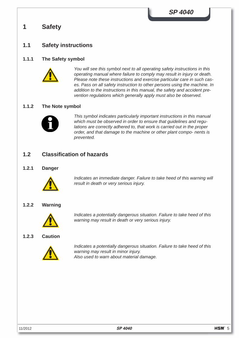
1.1.1 The Safety symbol
You will see this symbol next to all operating safety instructions in this operating manual where failure to comply may result in injury or death. Please note these instructions and exercise particular care in such cas-es. Pass on all safety instruction to other persons using the machine. In addition to the instructions in this manual, the safety and accident pre-vention regulations which generally apply must also be observed.
1.1.2 The Note symbol
This symbol indicates particularly important instructions in this manual which must be observed in order to ensure that guidelines and regu-lations are correctly adhered to, that work is carried out in the proper order, and that damage to the machine or other plant compo- nents is prevented.
1.2 Classifi cation of hazards
1.2.1 Danger
Indicates an immediate danger. Failure to take heed of this warning willresult in death or very serious injury.
1.2.2 Warning
Indicates a potentially dangerous situation. Failure to take heed of this warning may result in death or very serious injury.
1.2.3 Caution
Indicates a potentially dangerous situation. Failure to take heed of this warning may result in minor injury.Also used to warn about material damage.
6 SP 4040 11/2012
SP 4040
1.3 Safety instructions
Pay particular attention to the following safety instructions:
– The shredder-press combination SP 4040 has been inspected for safety by the exam-ination board of the technical committee of TÜV Rheinland. Nevertheless, incorrect operation and misuse can result in:
• injury or death to the operator • damage to the machine and other material assets of the company • ineffi cient machine operation
– The shredder-press combination SP 4040 baling press has been built with the most up-to-date technology. However, the machine can be dangerous if improperly used, even by trained staff, or if used for purposes other than those for which it was designed.
– The operation of the shredder-press combination is always subject to local safety and accident prevention regulations.
– The employer has to observe and to keep the „Minimum safety and health require-ments for use of the work equipment by workers at work. (2009/104/EG)
– The shredder-press combination may not be operated by anyone under 16 years of age.
– All those charged with installation, assembly, disassembly, start-up, operation, inspec-tion, maintenance or repair of the shredder-press combination must have fi rst read and fully understood the entire operating manual, paying particular attention to the "Safety" section.
– The shredder-press combination may only be operated, serviced and repaired by au-thorised, trained staff. These staff must have been given special instructions on any dangers which may possibly arise.
– Areas of personal responsibility for installation, assembly, re-assembly, set-up, opera-tion and maintenance must be clearly defi ned and strictly adhered to, in order to avoid confusion which might compromise safety.
– When carrying out installation, disassembly, re-assembly, maintenance, operation, ad-justment and maintenance work always observe the shut-down procedures described in the operating manual. Never perform this kind of work on the machine unless it is fully shut down.
– Before performing such tasks make sure the drives and additional mechanisms of the shredder-press combination cannot be switched on unintentionally. Turn the main switch to the "0" position and secure it. Pull out the mains plug.
– Before starting the machine after repairs, make sure all protective devices are in place.
11/2012 SP 4040 7
SP 4040
– Do not carry out any tasks which may endanger your safety while operating the ma-chine.
– Any changes which take place and could impair safety should be reported immediately. Put the machine out of operation until the damage is rectifi ed.
– Always make sure the machine is in perfect condition before you switch it on.
– Make sure the area around the shredder-press combination is clean and safe.
– Unauthorised modifi cations and changes to the machine are strictly prohibited. Protec-tive devices may not be removed or otherwise rendered inoperative.
– No work on the machine which is not part of its normal operation may be performed while the machine is still running.
– Never open doors and fl aps before the machine has been shut down. Note the instruc-tion plate.
– Test the protective measures installed after any electrical or repair work.
– No platforms or other raised surfaces may be placed near the shredder-press combina-tion if they encroach on the specifi ed safety clearances.
– Connecting cables must be laid in such a way that they cannot be tripped over.
– Only persons with the appropriate skills and experience in hydraulics may carry out work on the hydraulic equipment.
– All lines, pipes and bolted joints must be regularly inspected for looseness, leaks and visible damage. Any damage must be repaired immediately. Escaping oil can cause fi re and injury!
– Any parts of the system and hydraulic pressure lines that need to be opened must be depressurised according to the assembly instructions before commencing repair work.
8 SP 4040 11/2012
SP 4040
1.4 Proper use
The shredder-press combination SP 4040 is solely to be used for pressing paper and cardborad (shredded or not shredded). The sturdy cutting mechanism is not damaged by paper clips and staples, credit cards, CD-ROMs and fl oppy discs.The shredder-press combination may only be operated by authorised, trained staff. Do not carry out any tasks which may endanger your safety while operating the machine.
Any other use is considered improper. The manufacturer accepts no liability for damage resulting from improper use - the operator carries sole responsibility for such use.
1.5 Inspecting the safety devices
Check the safety devices:
• At the start of each shift (if operation was interrupted) • At least once a week if the machine is operated continuously • After any maintenance or repair work
Check that the safety devices:
• Are in the correct condition • Are in the correct position • Are fi rmly secured • Are working properly
If any defects arise during operation stop the machine immediately and ensure that the defect is corrected.
Do not modify or remove any of the protective devices. Do not deactivate any of the pro-tective devices by modifying the machine.
Modifi cations to the machine are prohibited for safety reasons!
Warning!Defective safety devices can lead to serious accidents!Ensure that the shredder has been completely shut down immediately, should the safety devices become defective!Never reach into the cutting device while it is running, this could result in very serious injuries!The shredder may only be started, if all the safety devices are function-ing correctly.
Use the following checklist for your inspection. Correct any defects before starting the machine!
11/2012 SP 4040 9
SP 4040
1.5.1 Checklist for inspecting the safety devices
Photocopy this checklist for regular inspections.
Tick off the points if they are OK.
Do not start the machine until you have checked every point.
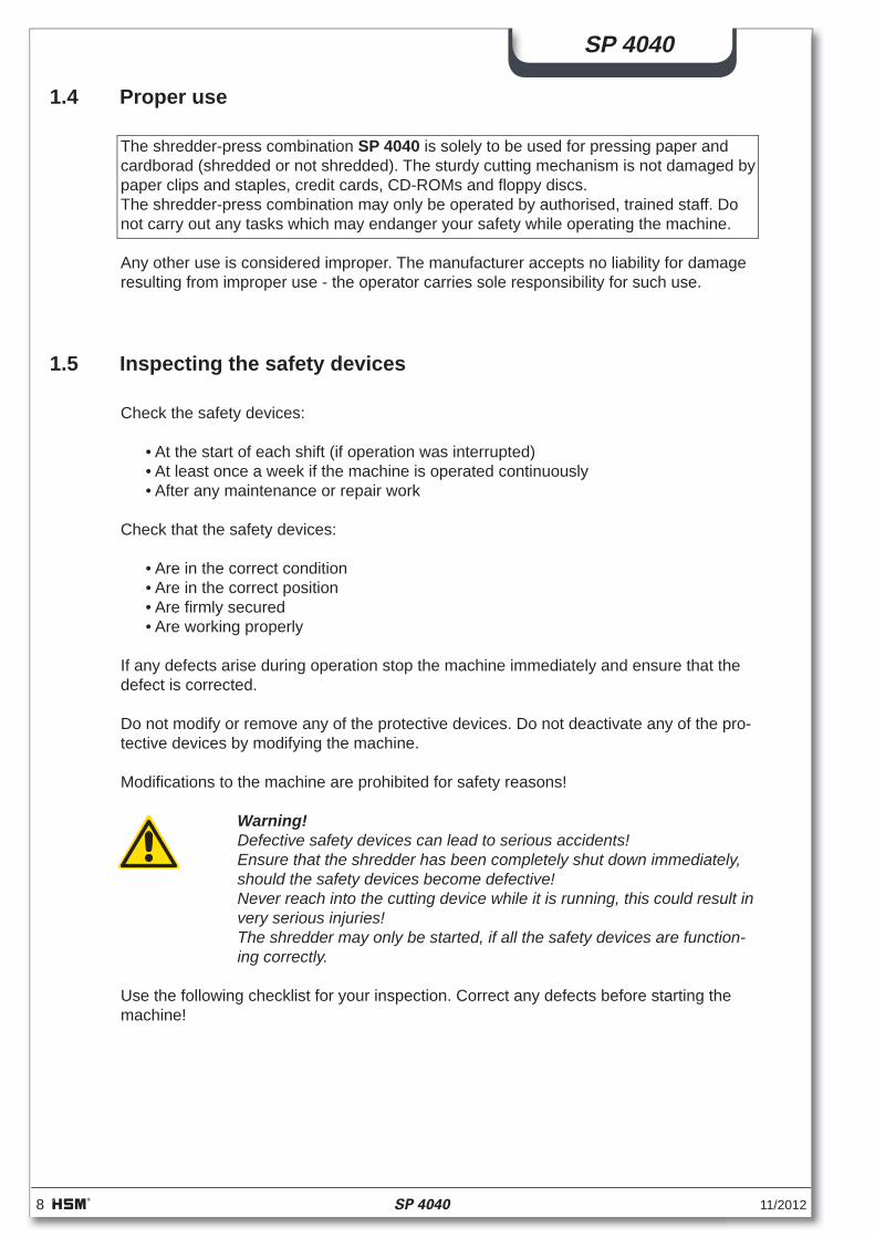
The warning sign must be fi xed to the control cabinet of the shredder-presscombination.
All protective covers must be mounted and fi rmly bolted onto the shredder and the shred-der-press combination (see picture)
Check the safety switch on the bale removal door (1). If the bale removal door is opened during operation, The shredder-press combi-nation and the shredder should switchoff immediately. It should not be possible to turn on any of the machines as long as the bale removal door is open. After the bale re-moval door has been shut, the "Ready" lamp on the shredder should light up again.
1
If you press the "Emergency Stop" button (2) on the shredder, it should switch off im-mediately and the "Ready" lamp should stop glowing. It should not be possible to turn the shredder on as long as the "Emergency Stop" button is locked. After the "Emergency Stop" has been unlocked, the "Ready" lamp should light up again.
2
Ein-Mann-BedienungOne-man operationUn seul opérateur
The safety label "One-man operation" must be attached on the shredder.
10 SP 4040 11/2012
SP 4040
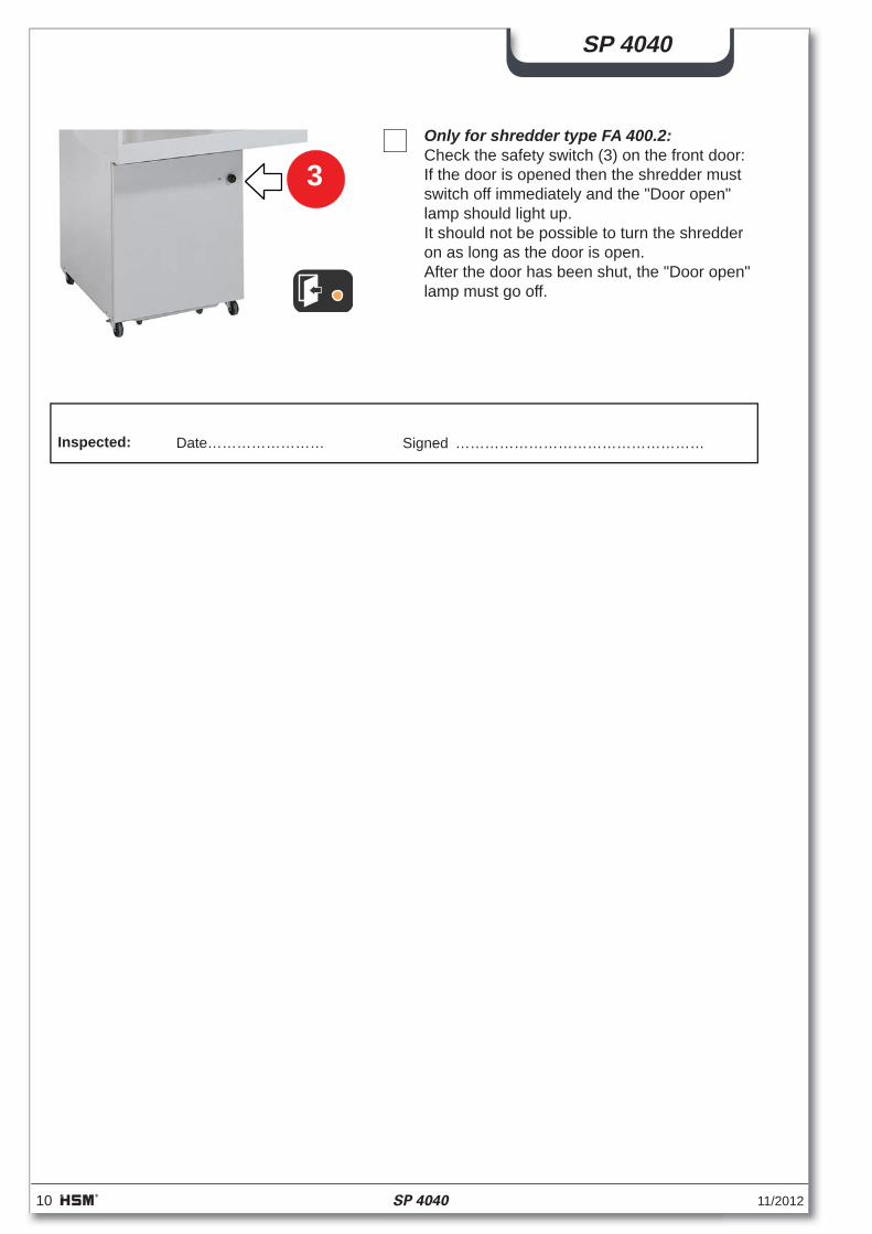
Date……………………Inspected: Signed ……………………………………………
Only for shredder type FA 400.2:Check the safety switch (3) on the front door:If the door is opened then the shredder must switch off immediately and the "Door open"lamp should light up.It should not be possible to turn the shredder on as long as the door is open.After the door has been shut, the "Door open"lamp must go off.
3
11/2012 SP 4040 11
SP 4040
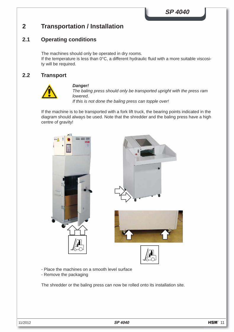
2 Transportation / Installation
Danger!The baling press should only be transported upright with the press ram lowered.If this is not done the baling press can topple over!
If the machine is to be transported with a fork lift truck, the bearing points indicated in the diagram should always be used. Note that the shredder and the baling press have a high centre of gravity!
2.2 Transport
2.1 Operating conditions
The machines should only be operated in dry rooms.If the temperature is less than 0°C, a different hydraulic fl uid with a more suitable viscosi-ty will be required.
- Place the machines on a smooth level surface- Remove the packaging
The shredder or the baling press can now be rolled onto its installation site.
12 SP 4040 11/2012
SP 4040
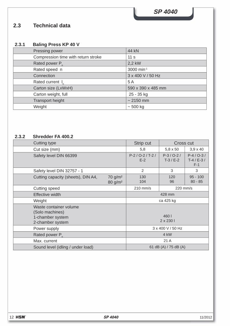
2.3 Technical data
2.3.1 Baling Press KP 40 VPressing power 44 kNCompression time with return stroke 11 sRated power Pn 2,2 kWRated speed n 3000 min-1
Connection 3 x 400 V / 50 HzRated current ln 5 ACarton size (LxWxH) 590 x 390 x 485 mmCarton weight, full 25 - 35 kgTransport height ~ 2150 mmWeight ~ 500 kg
2.3.2 Shredder FA 400.2Cutting type Strip cut Cross cutCut size (mm) 5,8 5,8 x 50 3,9 x 40
Safety level DIN 66399 P-2 / O-2 / T-2 / E-2
P-3 / O-2 / T-3 / E-2
P-4 / O-3 / T-4 / E-3 /
F-1Safety level DIN 32757 - 1 2 3 3
Cutting capacity (sheets), DIN A4, 70 g/m² 80 g/m²
130104
12096
95 - 10080 - 85
Cutting speed 210 mm/s 220 mm/s
Effective width 428 mm
Weight ca 425 kg
Waste container volume(Solo machines)1-chamber system2-chamber system
460 l2 x 230 l
Power supply 3 x 400 V / 50 Hz
Rated power Pn4 kW
Max. current 21 A
Sound level (idling / under load) 61 dB (A) / 75 dB (A)
11/2012 SP 4040 13
SP 4040
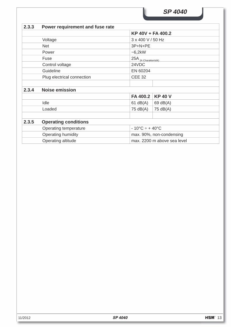
2.3.3 Power requirement and fuse rateKP 40V + FA 400.2
Voltage 3 x 400 V / 50 HzNet 3P+N+PEPower ~6,2kWFuse 25A (K-Charakteristik)
Control voltage 24VDCGuideline EN 60204Plug electrical connection CEE 32
2.3.4 Noise emissionFA 400.2 KP 40 V
Idle 61 dB(A) 69 dB(A)Loaded 75 dB(A) 75 dB(A)
2.3.5 Operating conditionsOperating temperature - 10°C ÷ + 40°COperating humidity max. 90%, non-condensingOperating altitude max. 2200 m above sea level
14 SP 4040 11/2012
SP 4040
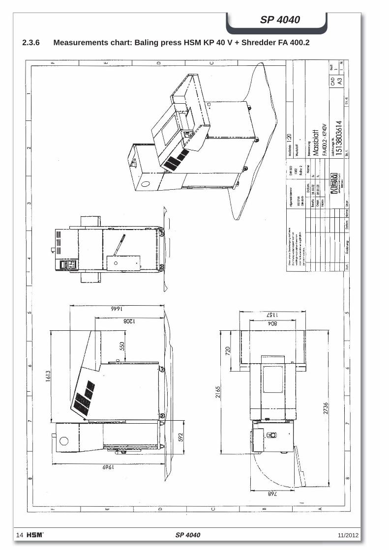
2.3.6 Measurements chart: Baling press HSM KP 40 V + Shredder FA 400.2
11/2012 SP 4040 15
SP 4040
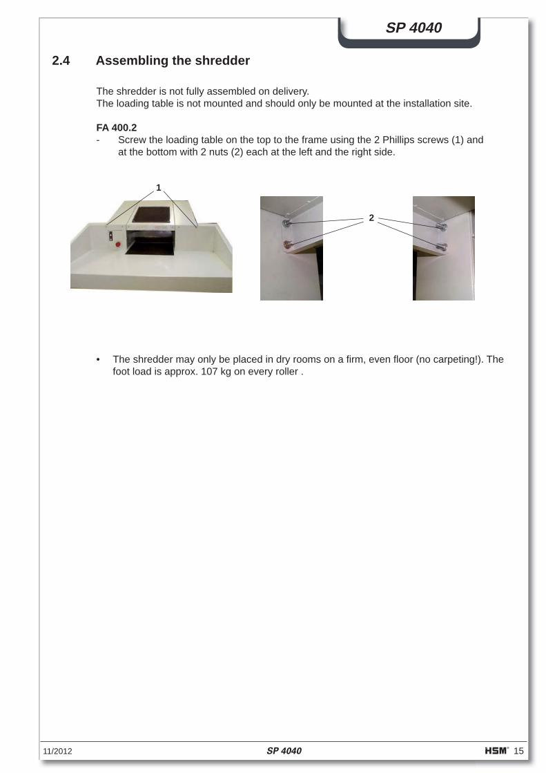
2.4 Assembling the shredder
The shredder is not fully assembled on delivery.The loading table is not mounted and should only be mounted at the installation site.
FA 400.2- Screw the loading table on the top to the frame using the 2 Phillips screws (1) and at the bottom with 2 nuts (2) each at the left and the right side.
1
2
• The shredder may only be placed in dry rooms on a fi rm, even fl oor (no carpeting!). The foot load is approx. 107 kg on every roller .
16 SP 4040 11/2012
SP 4040
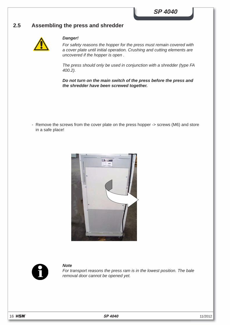
- Remove the screws from the cover plate on the press hopper -> screws (M6) and store in a safe place!
2.5 Assembling the press and shredder
Danger!For safety reasons the hopper for the press must remain covered with a cover plate until initial operation. Crushing and cutting elements are uncovered if the hopper is open .
The press should only be used in conjunction with a shredder (type FA400.2).
Do not turn on the main switch of the press before the press and the shredder have been screwed together.
NoteFor transport reasons the press ram is in the lowest position. The bale removal door cannot be opened yet.
11/2012 SP 4040 17
SP 4040
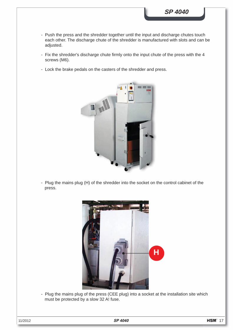
- Push the press and the shredder together until the input and discharge chutes touch each other. The discharge chute of the shredder is manufactured with slots and can be adjusted.
- Fix the shredder's discharge chute fi rmly onto the input chute of the press with the 4 screws (M6).
- Lock the brake pedals on the casters of the shredder and press.
- Plug the mains plug (H) of the shredder into the socket on the control cabinet of the press.
- Plug the mains plug of the press (CEE plug) into a socket at the installation site which must be protected by a slow 32 A! fuse.
H
18 SP 4040 11/2012
SP 4040
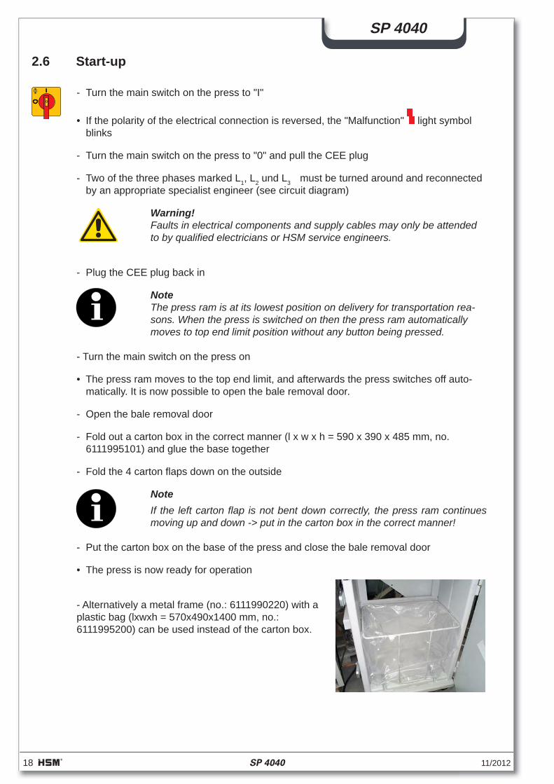
2.6 Start-up
- Turn the main switch on the press to "I"
• If the polarity of the electrical connection is reversed, the "Malfunction" light symbol blinks
- Turn the main switch on the press to "0" and pull the CEE plug
- Two of the three phases marked L1, L2 und L3 must be turned around and reconnected by an appropriate specialist engineer (see circuit diagram)
Warning!Faults in electrical components and supply cables may only be attended to by qualifi ed electricians or HSM service engineers.
- Plug the CEE plug back in
NoteThe press ram is at its lowest position on delivery for transportation rea-sons. When the press is switched on then the press ram automatically moves to top end limit position without any button being pressed.
- Turn the main switch on the press on
• The press ram moves to the top end limit, and afterwards the press switches off auto-matically. It is now possible to open the bale removal door.
- Open the bale removal door
- Fold out a carton box in the correct manner (l x w x h = 590 x 390 x 485 mm, no. 6111995101) and glue the base together
- Fold the 4 carton fl aps down on the outside
NoteIf the left carton fl ap is not bent down correctly, the press ram continues moving up and down -> put in the carton box in the correct manner!
- Put the carton box on the base of the press and close the bale removal door
• The press is now ready for operation
- Alternatively a metal frame (no.: 6111990220) with a plastic bag (lxwxh = 570x490x1400 mm, no.:6111995200) can be used instead of the carton box.
11/2012 SP 4040 19
SP 4040
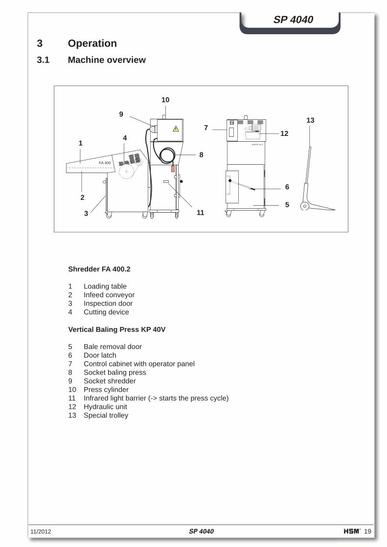
3 Operation
Vertical Baling Press KP 40V
5 Bale removal door6 Door latch7 Control cabinet with operator panel8 Socket baling press9 Socket shredder10 Press cylinder11 Infrared light barrier (-> starts the press cycle)12 Hydraulic unit13 Special trolley
Shredder FA 400.2
1 Loading table2 Infeed conveyor3 Inspection door4 Cutting device
3.1 Machine overview
13
FA 400
HSM KP 40 V
0
8
9
3
6
5
1
2
10
11
74 12
20 SP 4040 11/2012
SP 4040
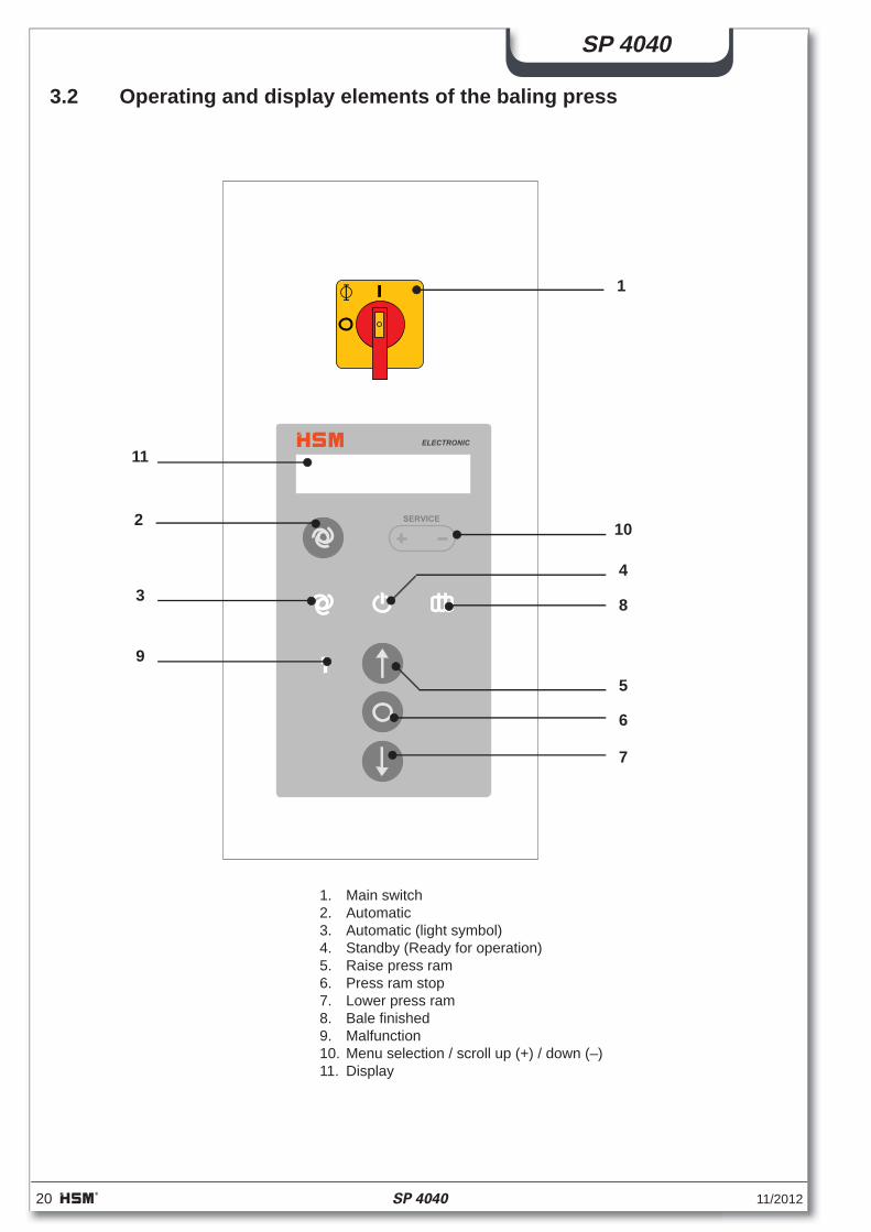
3.2 Operating and display elements of the baling press
1. Main switch2. Automatic3. Automatic (light symbol)4. Standby (Ready for operation)5. Raise press ram6. Press ram stop7. Lower press ram8. Bale fi nished9. Malfunction10. Menu selection / scroll up (+) / down (–)11. Display
SERVICE
ELECTRONIC
11
2
8
4
10
9
6
7
3
5
1
11/2012 SP 4040 21
SP 4040
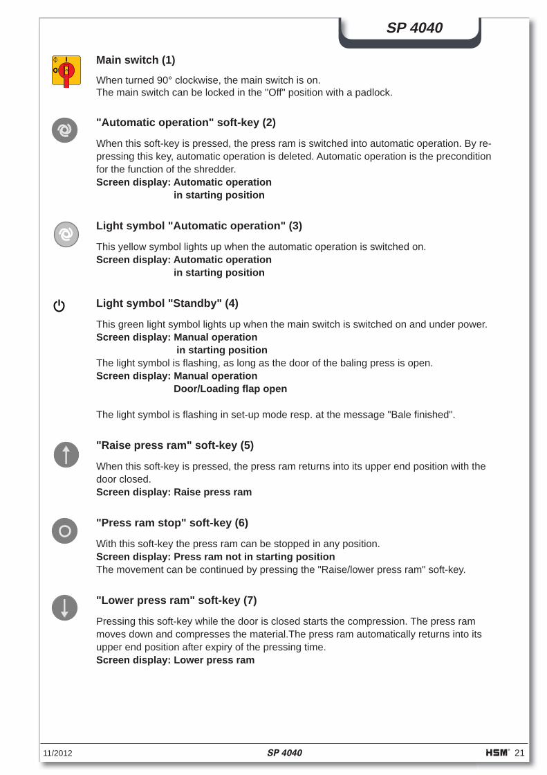
Main switch (1)
When turned 90° clockwise, the main switch is on.The main switch can be locked in the "Off" position with a padlock.
"Automatic operation" soft-key (2)
When this soft-key is pressed, the press ram is switched into automatic operation. By re-pressing this key, automatic operation is deleted. Automatic operation is the precondition for the function of the shredder.Screen display: Automatic operation in starting position
Light symbol "Automatic operation" (3)
This yellow symbol lights up when the automatic operation is switched on.Screen display: Automatic operation in starting position
Light symbol "Standby" (4)
This green light symbol lights up when the main switch is switched on and under power.Screen display: Manual operation in starting positionThe light symbol is fl ashing, as long as the door of the baling press is open.Screen display: Manual operation Door/Loading fl ap open
The light symbol is fl ashing in set-up mode resp. at the message "Bale fi nished".
"Raise press ram" soft-key (5)
When this soft-key is pressed, the press ram returns into its upper end position with the door closed.Screen display: Raise press ram
"Press ram stop" soft-key (6)
With this soft-key the press ram can be stopped in any position. Screen display: Press ram not in starting positionThe movement can be continued by pressing the "Raise/lower press ram" soft-key.
"Lower press ram" soft-key (7)
Pressing this soft-key while the door is closed starts the compression. The press ram moves down and compresses the material.The press ram automatically returns into its upper end position after expiry of the pressing time.Screen display: Lower press ram
22 SP 4040 11/2012
SP 4040
Light symbol "Bale fi nished" (8)
This message is displayed when a certain fi lling height of the carton box is reached. The shredder is switched off. The press ram automatically moves into its upper end position. As soon as this position is reached, the motor of the press is switched off.The "Bale fi nished" message goes off, when the door is opened.
Light symbol "Malfunction" (9)
This message is displayed when there is any malfunction on the combination press. Combi-nation press and paper shredder are switched off and a malfunction number appears on the screen. (-> see section "Malfunctions")
Screen display (11)
On the display are shown the running states and the error messages. (-> see section "Malfunctions")
11/2012 SP 4040 23
SP 4040
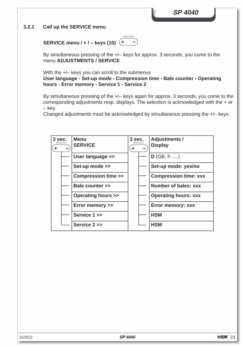
3.2.1 Call up the SERVICE menu
SERVICE menu / + / – keys (10)
By simultaneous pressing of the +/– keys for approx. 3 seconds, you come to the menu ADJUSTMENTS / SERVICE
With the +/– keys you can scroll to the submenusUser language - Set-up mode - Compression time - Bale counter - Operating hours - Error memory - Service 1 - Service 2
By simultaneous pressing of the +/– keys again for approx. 3 seconds, you come to the corresponding adjustments resp. displays. The selection is acknowledged with the + or– key.Changed adjustments must be acknowledged by simultaneous pressing the +/– keys.
SERVICE
3 sec. MenuSERVICE
3 sec. Adjustments / Display
User language >> D (GB, F, ....)
Set-up mode >> Set-up mode: yes/no
Compression time >> Compression time: xxx
Bale counter >> Number of bales: xxx
Operating hours >> Operating hours: xxx
Error memory >> Error memory: xxx
Service 1 >> HSM
Service 2 >> HSM
SERVICE SERVICE

24 SP 4040 11/2012
SP 4040
3.2.2 Adjusting the user language
- Switch on main switch Screen display: Ready or Press ram not in starting postion.
The screen display can be adjusted for different user languages.The following ones are available:D - GB - F - E - I - P - NL - S - FIN - DK - GR - TR - PL - CZ - HU - RUS
- Simultaneously press the +/– keys for approx. 3 seconds Screen display: Selection with +/- User language
- Simultaneously press the +/– keys for approx. 3 seconds Screen display: User language D
- Scroll to the desired language using the +/– keys - Press the +/– keys simultaneaously for acknowledgement
SERVICE
ELECTRONIC
11/2012 SP 4040 25
SP 4040
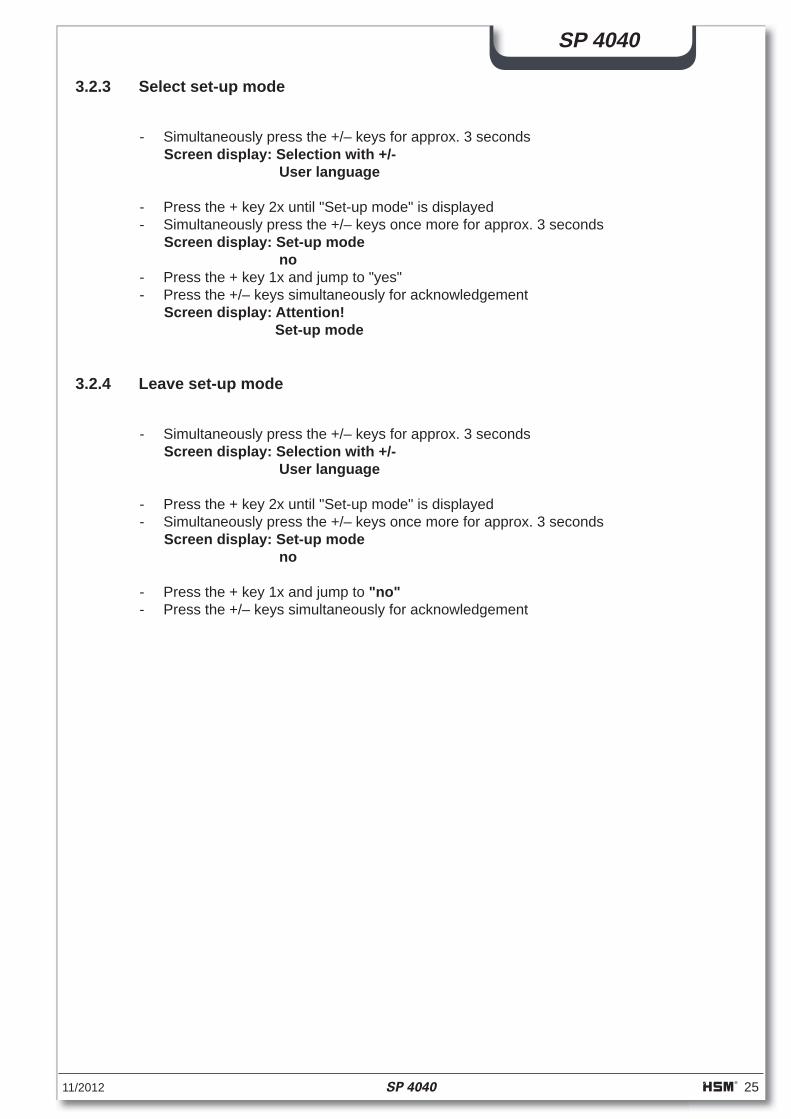
3.2.3 Select set-up mode
- Simultaneously press the +/– keys for approx. 3 seconds Screen display: Selection with +/- User language
- Press the + key 2x until "Set-up mode" is displayed - Simultaneously press the +/– keys once more for approx. 3 seconds
Screen display: Set-up mode no - Press the + key 1x and jump to "yes" - Press the +/– keys simultaneously for acknowledgement
Screen display: Attention! Set-up mode
3.2.4 Leave set-up mode
- Simultaneously press the +/– keys for approx. 3 seconds Screen display: Selection with +/- User language
- Press the + key 2x until "Set-up mode" is displayed - Simultaneously press the +/– keys once more for approx. 3 seconds
Screen display: Set-up mode no
- Press the + key 1x and jump to "no" - Press the +/– keys simultaneously for acknowledgement
26 SP 4040 11/2012
SP 4040
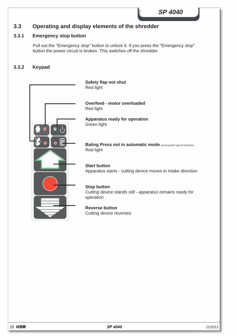
3.3 Operating and display elements of the shredder3.3.1 Emergency stop button
Pull out the "Emergency stop" button to unlock it. If you press the "Emergency stop"button the power circuit is broken. This switches off the shredder.
3.3.2 Keypad
Safety fl ap not shut Red light
Overfeed - motor overloaded Red light
Apparatus ready for operation Green light
Baling Press not in automatic mode (corresponds bag full indicator)
Red light
Start button Apparatus starts - cutting device moves in intake direction
Stop button Cutting device stands still - apparatus remains ready for operation Reverse button Cutting device reverses
11/2012 SP 4040 27
SP 4040
3.4 Operation
The press is now ready for operation if:• The main switch on the press is on• The bale removal door is shut• No error message is present• Screen display: Manual operation - in starting position
The shredder is now ready for operation if:• The mains plug for the shredder is plugged into the control cabinet of the baling press• The "Emergency stop" button is unlocked• The green symbol is glowing
- Press the green arrow key (=start key)
- Place the material to be shredded on the loading table and then place batches on the infeed conveyor
If material that is not supposed to be shredded is mistakenly placed onto the conveyor belt do not try to pull it out, but
- First press the "Stop" key and then press the reverse key after the shredder has come to a standstill
• The shredder is now running in reverse- When the reverse key is released the shredder comes to a stand still
- The material can now be removed from the conveyor belt and the shredder can be started again with the start key
The shredded material falls through the discharge chute of the shredder directly into the carton box inside the press.The press cycle is initiated by the infrared light barrier when the carton box has been fi lled to a certain level. The press ram moves downwards, presses the material into the carton box, (alternatively: into the plastic bag) switches over automatically and moves back to its starting position.The shredder continues to run during the press cycle.
The fi lling and press cycle continues until the "Bale fi nished" light symbol appears on the display and the blue light symbol "Bale fi nished" lights up.At the same time the shredder switches off. The shredder can now only be operated in reverse direction.The press ram moves to its upper end position. As soon as this position is reached, the motor of the press is switched off and the light symbol "Automatic" goes off. The "Bale fi nished" light symbol disappears as soon as the bale removal door is opened.
- Press the "Automatic key" on the balling press Screen display: Automatic in starting position
28 SP 4040 11/2012
SP 4040
3.4.1 Repressing
- Acknowledge the "Bale fi nished" message with the "Stop" key• the message disappears
- Press the "Press ram down" key• The press ram moves down onto the material, switches over automatically and moves back to its upper end position• The yellow "Bales ready" lamp lights up again
NoteIn order to achieve an optimum compression of the material, it may be necessary to repeat the press cycle 1-2 times.
FA 400
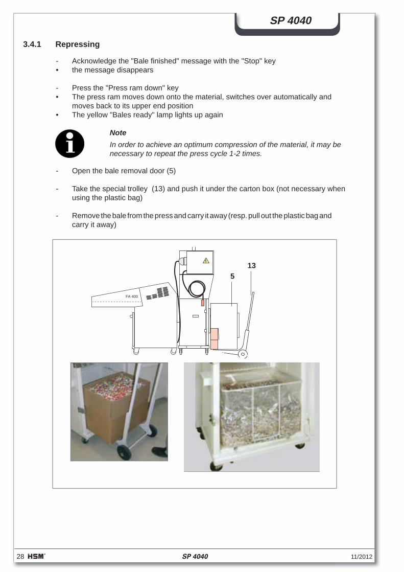
- Open the bale removal door (5)
- Take the special trolley (13) and push it under the carton box (not necessary when using the plastic bag)
- Remove the bale from the press and carry it away (resp. pull out the plastic bag and carry it away)
513
11/2012 SP 4040 29
SP 4040
- Fold out a carton box in the correct manner (l x w x h = 590 x 390 x 485 mm) and glue the base together (alternatively a plastic bag can be inserted instead of the carton box -> see chapter "Start-up")
- Fold the 4 carton fl aps down net on the outside
NoteIf the left carton fl ap is not bent down correctly, the press ram continues moving up and down -> insert the carton box correctly!
- Put the carton box on the base of the press- Close the bale removal door and lock it• The press and the shredder are now ready for operation again
30 SP 4040 11/2012
SP 4040
- Turn the main switch on the press off.
- Secure the main switch with a padlock to prevent unauthorised use.
- Pull out the baling press mains plug off the onsite socket.
3.5 Shredder combination shutdown
- Press the "Stop" key on the shredder
- Turn the main switch on the shredder off.
- Secure the main switch with a padlock to prevent unauthorised use.
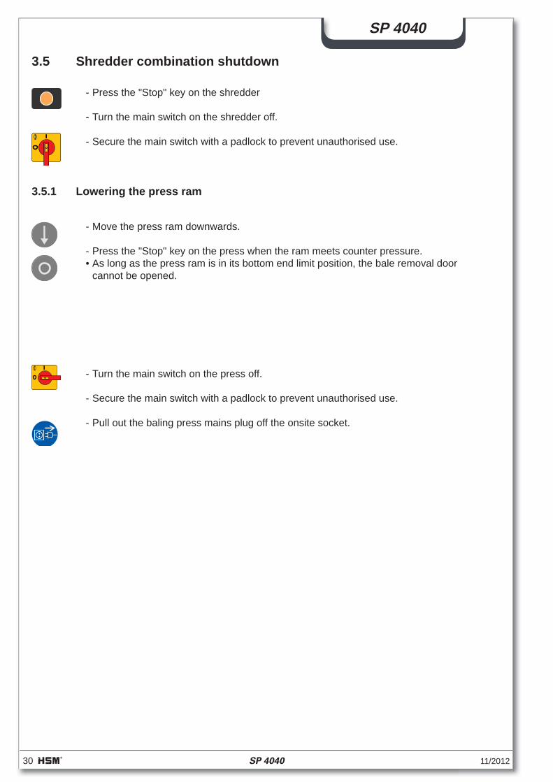
3.5.1 Lowering the press ram
- Move the press ram downwards.
- Press the "Stop" key on the press when the ram meets counter pressure. • As long as the press ram is in its bottom end limit position, the bale removal door
cannot be opened.
11/2012 SP 4040 31
SP 4040
4 Faults / troubleshooting
Warning!Faults in electrical components and supply cables may only be attended to by qualifi ed electricians or HSM service engineers.
Before any work on the control cabinet:Turn off the main switch!
Note the warning plates:
4.1 Malfunctions shredder
If the cutting device is overloaded, the shredder switches automatically to reverse opera-tion:
• The shredder stops• The red LED on the keypad lights up• The shredder runs in reverse for a bout 2 seconds and then stops again
- Divide the pile of paper and press the start key again
• Shredder runs forward
- Take care that any further loads are made up of rather less paper
Frequent overloading:
• The electric motor overheats• The red LED on the keypad lights up• The shredder switches off automatically
- Allow the shredder's electric motor around 20–30 minutes to cool down and afterwards start the equipment again
NoteLoad the shredder in equal amounts that fall within the shredder's perfor-mance range. This avoids time consuming reverse cycles and enables you to run the machine at its maximum throughput capacity.
ATTENTION !Voltage also present when master switch is turned off.ATTENTION !Sous tension, même en position d'arrêt de l'interrupteur principal.
ACHTUNG !Auch bei ausgeschaltetem Hauptschalter unter Spannung.
Fremdspannung!External voltage!Tension étrangère!
32 SP 4040 11/2012
SP 4040
NoteThe press ram moves constantly up and down if• The infrared light barrier is dirty -> clean it.• The left hand fl ap of the carton is not folded down -> insert carton correctly.
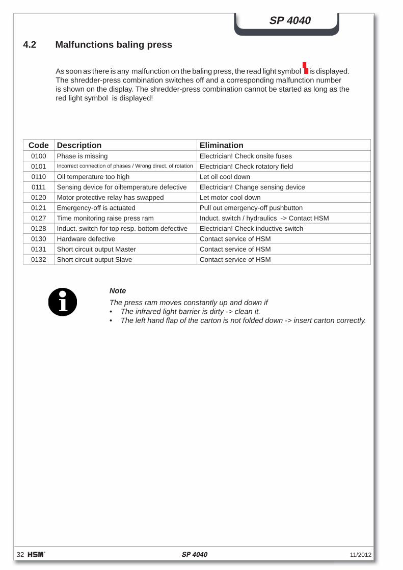
4.2 Malfunctions baling press
As soon as there is any malfunction on the baling press, the read light symbol is displayed.The shredder-press combination switches off and a corresponding malfunction numberis shown on the display. The shredder-press combination cannot be started as long as the red light symbol is displayed!
Code Description Elimination0100 Phase is missing Electrician! Check onsite fuses0101 Incorrect connection of phases / Wrong direct. of rotation Electrician! Check rotatory fi eld0110 Oil temperature too high Let oil cool down0111 Sensing device for oiltemperature defective Electrician! Change sensing device0120 Motor protective relay has swapped Let motor cool down0121 Emergency-off is actuated Pull out emergency-off pushbutton0127 Time monitoring raise press ram Induct. switch / hydraulics -> Contact HSM0128 Induct. switch for top resp. bottom defective Electrician! Check inductive switch0130 Hardware defective Contact service of HSM0131 Short circuit output Master Contact service of HSM0132 Short circuit output Slave Contact service of HSM
11/2012 SP 4040 33
SP 4040
5 Maintenance
5.1 General instructions
All the inspection and maintenance tasks listed here apply to single-shift operation. If the machine is being operated in multiple shifts it must be checked more frequently.
Warning!Before undertaking any maintenance or cleaning work on the baling press or shredder:• Turn off both main switches and secure against starting accidentally• Pull out the mains plug for the baling press
Always refer to the "Safety" chapter during maintenance and inspection work.
Among other factors, the operational safety and the longevity of the baling press depend on properly carried out maintenance.
Since operating conditions may vary, it is impossible to specify in advance how often wear check, inspections, maintenance and repairs will be necessary. A suitable inspec-tion routine should be devised according to your particular operating conditions.
Our customer service experts will be glad to assist you with additional advice.
Maintenance work may only be carried out by our specialist engineers or speciallytrained staff.
The baling press must undergo a complete overhaul at least every two years.
Before beginning work, always check all cables, pipes and screw connections for leaks, looseness and visible damage.
Warning!Correct any damage immediately! Escaping oil can cause fi re and injury!
Maintenance and repair work on the electrical system or control cabinet may only be carried out by a qualifi ed electrician or one of our service engineers!
34 SP 4040 11/2012
SP 4040
HSM KP 40 V
0
5.2 Baling press
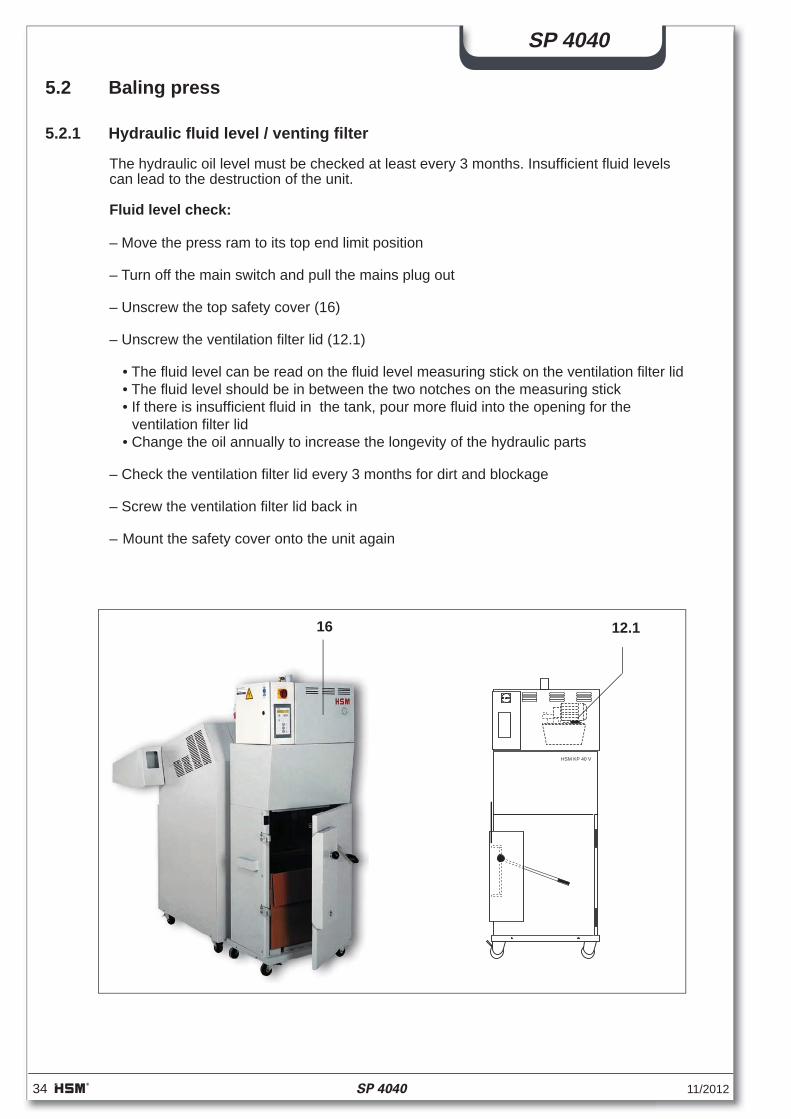
5.2.1 Hydraulic fl uid level / venting fi lter
The hydraulic oil level must be checked at least every 3 months. Insuffi cient fl uid levels can lead to the destruction of the unit.
Fluid level check:
– Move the press ram to its top end limit position
– Turn off the main switch and pull the mains plug out
– Unscrew the top safety cover (16)
– Unscrew the ventilation fi lter lid (12.1)
• The fl uid level can be read on the fl uid level measuring stick on the ventilation fi lter lid• The fl uid level should be in between the two notches on the measuring stick• If there is insuffi cient fl uid in the tank, pour more fl uid into the opening for the
ventilation fi lter lid• Change the oil annually to increase the longevity of the hydraulic parts
– Check the ventilation fi lter lid every 3 months for dirt and blockage
– Screw the ventilation fi lter lid back in
– Mount the safety cover onto the unit again
16 12.1
11/2012 SP 4040 35
SP 4040
5.2.2 Changing the hydraulic fl uid
Change the hydraulic fl uid annually:
– Move the press ram to its top end limit position
– Turn off the main switch and pull the mains plug out
– Unscrew the top safety cover
– Place a container to catch the fl uid under the fl uid drain plug or use a fl uid suction unit
• The capacity of the hydraulic fl uid tank is ~11 l
– Unscrew the oil drain plug on the side of the fl uid tank with a hexagon socket spanner and use a container to catch the fl uid
– If the tank is very dirty, clean it
– Screw the fl uid drain plug back in (renew seal)
– Fill with the prescribed amount of fl uid
Oil type: Multi-grade oil DIN 51524-T3 / ISO viscosity grade HVLP 22
– Turn on the main switch
– Move the press ram up and down several times and check the fl uid again (as de-scribed above) with the press ram in its topmost position
– Fill more oil if required
– Unscrew the ventilation fi lter lid again
– Mount the safety cover onto the unit again
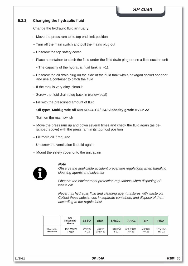
NoteObserve the applicable accident prevention regulations when handling cleaning agents and solvents!
Observe the environment protection regulations when disposing of waste oil!
Never mix hydraulic fl uid and cleaning agent mixtures with waste oil! Collect these substances in separate containers and dispose of them according to the regulations!
MineralöleMineral oils
ISO VG 22HVLP
ISO-Viskositäts-
klasseARAL BPESSO DEA FINA
Aral Vitam HF 22
BartranHV 22
UNIVIS N 22
AstronZHLP 22
HYDRANHV 22
Tellus ÖlT 22
SHELL
36 SP 4040 11/2012
SP 4040
5.3 Shredder
5.3.1 Cleaning cutting device (1x daily)
Strip cut machines:
- Switch off the shredder at the main switch. - Spray cutting block special oil through the paper inlet opening onto the cutting rollers.
Order no. 1.235.997.401 for 250 ml-bottle Order no. 1.235.997.500 for 5 l-tank
- Let the cutting device run forwards and backwards several times without feeding in any paper.
• This loosens paper dust and particles.
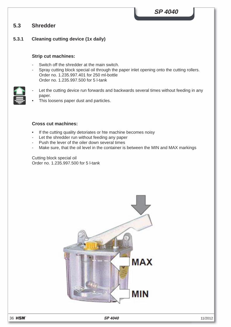
Cross cut machines:
• If the cutting quality detoriates or hte machine becomes noisy - Let the shredder run without feeding any paper - Push the lever of the oiler down several times - Make sure, that the oil level in the container is between the MIN and MAX markings
Cutting block special oilOrder no. 1.235.997.500 for 5 l-tank
11/2012 SP 4040 37
SP 4040
If you need to adjust the chain tension on a FA 400.2:
- Remove the cover plate on the right hand side
- Loosen the nuts and push the motor with the tensioning screws until the chain sag is between 4 – 10 mm
- Tighten the nuts again
- Mount the cover plate and the loading table onto the unit again.
NoteDo not tighten the chain too much as this will wear the chain and the bearings faster than would otherwise be the case.
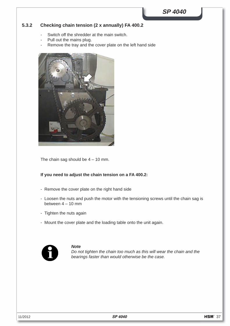
The chain sag should be 4 – 10 mm.
5.3.2 Checking chain tension (2 x annually) FA 400.2
- Switch off the shredder at the main switch. - Pull out the mains plug. - Remove the tray and the cover plate on the left hand side
38 SP 4040 11/2012
SP 4040
5.3.3 Greasing drive chains and cogs (2x annually) FA 400.2
- Switch off the shredder - Pull out the mains plug - Remove the left and right cover panels. - Grease the cogs and the drive chains from the motor to the cutting device, the cutting
block to the feeding belt and the cutting block to the regulating roller. Recommended lubricating grease: K2K in accordance with DIN 51502/DIN 51825
- Put the side cover panels and the tray back on
NLGI-Klasse ARAL BPDEAESSO MOBIL
2 -3Wälzlagerfett(lithiumverseift)
Bearing grease(lithium saponified)
AralubHL 3
EnergreaseLS 3
Glissando 30
ExxonBEACON 2
MobiluxEP 2
ALVANIAFett R 3
SHELL
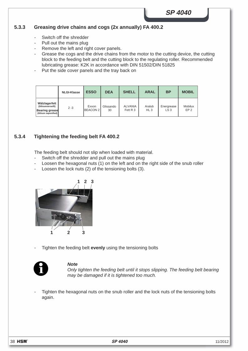
5.3.4 Tightening the feeding belt FA 400.2
The feeding belt should not slip when loaded with material. - Switch off the shredder and pull out the mains plug - Loosen the hexagonal nuts (1) on the left and on the right side of the snub roller - Loosen the lock nuts (2) of the tensioning bolts (3).
1
1 2 3
2 3
- Tighten the feeding belt evenly using the tensioning bolts
NoteOnly tighten the feeding belt until it stops slipping. The feeding belt bearing may be damaged if it is tightened too much.
- Tighten the hexagonal nuts on the snub roller and the lock nuts of the tensioning bolts again.
11/2012 SP 4040 39
SP 4040
5.3.4.1 Check, that the feeding belt runs straight
Switch on the shredder and let it run for 10 minutes.During this time, the feeding belt must run in the middle of the snub roller. If it slips to the left or right edge, you must alter the setting of the snub roller
5.3.4.2 Checking the feeding belt for wear
The surface of the feeding belt can become worn after long periods of use. If you can see the fabric inlay in the belt, it must be replaced. Please notify our customer service.
6 Disposal instructions
HSM baling presses / shredders have a long service life. Nevertheless, every machinereaches a time when inspections and repairs are no longer worth the trouble. The opera-tor then faces the problem of disposing of the machine properly.
We will be glad to advise you about the legal regulations for disposal at theappropriate time.
The baling press and shredder are made of different materials and need to be disassem-bled to separate the materials for recycling. (Ferrous materials, electrical components,plastics)
The hydraulic tank, pipes and hoses must be drained. It is important to ensure thatleaking or spilled liquids are disposed of using appropriate binding agents or technicalfacilities, and do not enter the water, the ground or the sewer system.In disposing of the respective hydraulic fl uids, the national legal requirements must beobserved.

40 SP 4040 11/2012
SP 4040
6.1 Disposal verifi cation form
To
HSM GmbH + Co. KG
Austraße 1 - 9
D-88699 Frickingen / Germany
The machine specifi ed here
Designation: Baling press / Shredder
Model: ______________________________
Machine number: ______________________________
Year of construction: ______________________________
has been disposed of according the applicable regulations.
Address of the lastoperating company
Address of thewaste management company
............................................... ...............................................Date and signature Date and signatureof the last operator of the disposal company
11/2012 SP 4040 41
SP 4040
HSM GmbH+Co.KGAustrasse 1-9D-88 699 FrickingenGermany
MODELLMASCH.-NR.:SERIEN - NR.: PRESSKRAFT: kN
zH V :GNUNNAPS
BAUJAHR:
LEISTUNG: kW
NENNSTROM: A
7 Electrical and hydraulic circuit diagrams
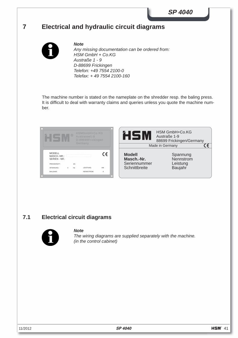
NoteAny missing documentation can be ordered from:HSM GmbH + Co.KGAustraße 1 - 9D-88699 FrickingenTelefon: +49 7554 2100-0Telefax: + 49 7554 2100-160
The machine number is stated on the nameplate on the shredder resp. the baling press. It is diffi cult to deal with warranty claims and queries unless you quote the machine num-ber.
HSM GmbH+Co.KGAustraße 1-988699 Frickingen/Germany
Schnittbreite Baujahr
Spannung
LeistungNennstromMasch.-Nr.
Modell
Made in Germany
Seriennummer
7.1 Electrical circuit diagrams
NoteThe wiring diagrams are supplied separately with the machine.(in the control cabinet)
42 SP 4040 11/2012
SP 4040
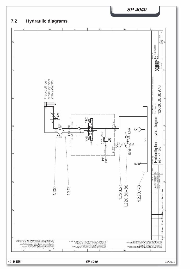
7.2 Hydraulic diagrams
11/2012 SP 4040 43
SP 4040
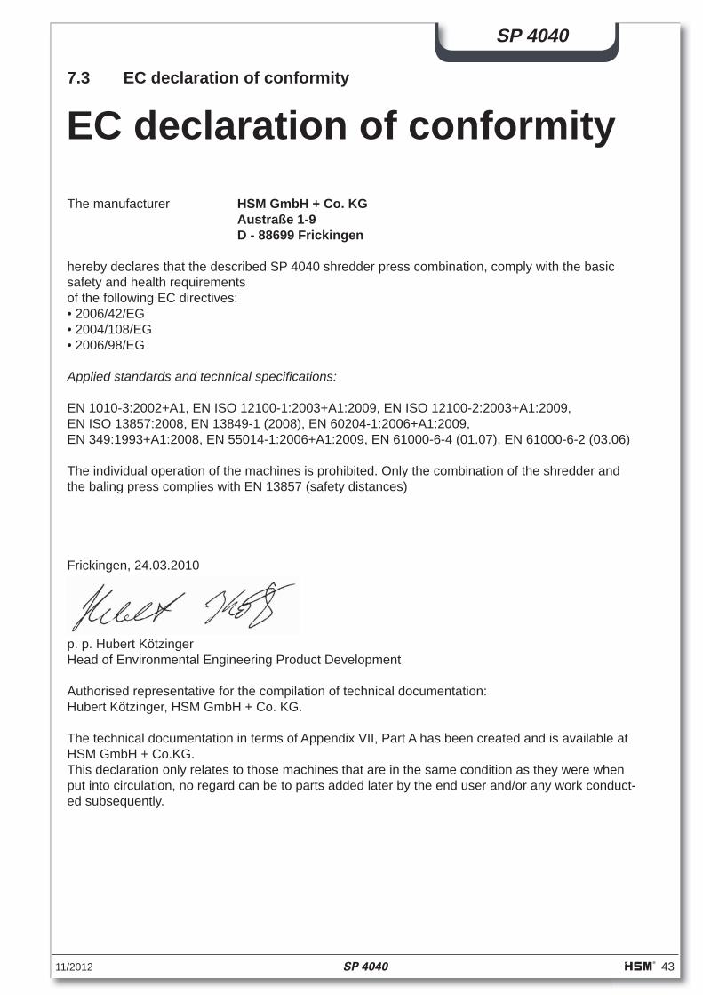
7.3 EC declaration of conformity
The manufacturer HSM GmbH + Co. KG Austraße 1-9 D - 88699 Frickingen
hereby declares that the described SP 4040 shredder press combination, comply with the basic safety and health requirementsof the following EC directives: • 2006/42/EG• 2004/108/EG• 2006/98/EG
Applied standards and technical specifi cations: EN 1010-3:2002+A1, EN ISO 12100-1:2003+A1:2009, EN ISO 12100-2:2003+A1:2009, EN ISO 13857:2008, EN 13849-1 (2008), EN 60204-1:2006+A1:2009,EN 349:1993+A1:2008, EN 55014-1:2006+A1:2009, EN 61000-6-4 (01.07), EN 61000-6-2 (03.06)
The individual operation of the machines is prohibited. Only the combination of the shredder andthe baling press complies with EN 13857 (safety distances)
Frickingen, 24.03.2010
p. p. Hubert KötzingerHead of Environmental Engineering Product Development
Authorised representative for the compilation of technical documentation: Hubert Kötzinger, HSM GmbH + Co. KG.
The technical documentation in terms of Appendix VII, Part A has been created and is available atHSM GmbH + Co.KG.This declaration only relates to those machines that are in the same condition as they were whenput into circulation, no regard can be to parts added later by the end user and/or any work conduct-ed subsequently.
EC declaration of conformity