operating range s - salmson · pumping of clear or muddy, neutral or corro - sive fluids in the...
TRANSCRIPT

Pumping of clear or muddy, neutral or corro-sive fluids in the sectors of industry, muddy water pumping, site dewatering...Tractable diesel version for rapid interven-tion in case of flooding.
Application examples:• Removal of muddy water • Pumping seawater• Recirculation of industrial waste• Waste water pumping• Black water pumping
APPLICATIONS
OPERATING RANGEFlow rates up to: 500 m3/hMano. head up to: 60 m CEOperating pressure: 6 barTemperature range: - 40° to +140°C*Connection: 1”1/2 to 4”
DN40 to DN200Flange PN: PN10/16Max. solids: ≃ DN÷ 2* According to model
N.T. No 177-1/ENG. - Ed.5/10-14
SELF-PRIMINGCENTRIFUGAL PUMPS
• monobloc stainless steel S version
ADVANTAGES
• Self-priming capacity (up to 6m depen-ding on model and system condition) avoiding the use of a foot valve and the risk of unpriming.
• High level of abrasion resistance and use of wear plates which are easy to replace.
• Passage of large solid bodies of approxi-mately half the DN of the pump.
• External lubrication of the mechanical seal to extend its lifespan.
• Numerous material combinations cor-responding to a maximum number of applications.
• Versions equipped with a pe-trol or diesel thermal motor (contact us).
• S version on frame
500
60
S 40 à S 230
Qm3/h
Hm
S
1

CODIFICATION
1: Pump size (see curves)
2: Pump metal Code Pump body Impeller Shaft/ housing Wear plates
F Cast iron Cast iron Stainless steel Cast iron or Treated steel
E Cast iron S.steel 316 Stainless steel Stainless steel
Z Cast iron + Zinc anode Bronze or S.steel Stainless steel Bronze or S.steel
C* Cast iron + CERAM® Cast iron + CERAM® Stainless steel Cast iron or
Treated steelB Bronze Bronze Stainless steel BronzeX S.steel 316 S.steel 316 S.steel 316 Stainless steel
* C: available for S80 and above
3: Impervious material Available sizes Mechanical seals Gaskets Valves
A All SiC/Ceram/FPM NBR NBRB All SiC/Ceram/FPM FPM FPM
C
S40 to 42 WC/SiC/PTFE PTFE PTFE
S45 to 161 WC/SiC/PTFE(with bellows) PTFE PTFE PTFE or without
(depending on size)S170 to S230 WC/SiC/PTFE PTFE sans
F All Carbon/SiC/FPM NBR NBRG All Carbon/SiC/FPM FPM FPM
H S45 to 161 Carbon/SiC/PTFE PTFE PTFE PTFE or without (depending on size)
J All Carbon/SiC/EPDM EPDM EPDM K All WC/WC/NBR NBR NBR
4: Hydraulic configuration Code Openings Greaser Option
R Threaded With / S Flanged With / T* Threaded Without /
By c
onsu
ltatio
n
U* Flanged Without / C Threaded With With knife systemD Flanged With With knife systemF Threaded Without With flushingG Flanged Without With flushing
* for imperviousness J only
5: Pump motor assembly11
Monobloc
standard 12 on portable frame 13 on trolley14 on tractable trailer 21
Bibloc
standard 22 on portable frame23 on trolley24 on tractable trailer 31
Bearingon frame
32 on frame + spacer35 bare shaft end pump
6: Motor supplycode alimentation
T Three phaseM Single phaseD DieselE PetrolN Unit without motor
7: Motor power (in kW)
8: Number of poles (for electric motors) / Number of cylinders (for thermal motors)
9: Motor option (empty = no option)
• Options for electric motor:code option motor
K PTC probeS ON/OFF switch
• Options for thermal motor:code Brand Start-up Tank
A Lombardini Manual on motorB Lombardini Electric on motorC Lombardini Electric in frame E HATZ Manual on motorF HATZ Electric on motorG HATZ Electric in frame H HATZ - Silent Electric in frame N DEUTZ Electric in frame
10: ATEX brandcode Corresponding ATEX brand
2
A ZONE 1 - CAT.2 - II 2Gc B ZONE 1 - CAT.2 - II 2Gc - Ex d IIB T4 C ZONE 1 - CAT.2 - II 2Gc - Ex d IIC T4 D ZONE 1 - CAT.2 - II 2Gc - Ex de IIB T4 E ZONE 1 - CAT.2 - II 2Gc - Ex de IIC T4
3
A ZONE 2 - CAT.3 - II 3Gc B ZONE 2 - CAT.3 - II 3Gc - Ex d IIB T4 C ZONE 2 - CAT.3 - II 3Gc - Ex d IIC T4 D ZONE 2 - CAT.3 - II 3Gc - Ex de IIB T4 E ZONE 2 - CAT.3 - II 3Gc - Ex de IIC T4
S 40 F A R - 21 - T 11 / 2 K - 3B1 2 3 4 5 6 7 8 9 10
S
2

SELECTION ASSISTANCE
DESIGN
• Hydraulic section- Self-priming centrifugal pump with single-cell surface.
- Horizontal suction, vertical discharge.- Standard flanged connection or threaded openings.
• Imperviousness- Simple mechanical seal, optional flushing. - Automatic distribution lubrication cartridge.- Sleeved shaft (according to version).
• Motor section- Standard IEC ventilated motor form B3, B5 or specific long shaft.
Electric motor features:Output IE2 Network voltage: 1~220V (up to 1,1kW) 3~ 230/400V (up to 4kW) 3~ 400/690V (from 5,5kW)Frequency: 50 ou 60Hz (according to version)Number of poles: 2 – 4 – 6 (according to version)Insulation category : (F)Protection index: IP55 Probes: PTC (except monobloc)- Thermal motors available by consultation (assembled on frame or tractable trolley).
CREATION OF THE HYDRAULIC SECTION
SELF-PRIMING PRINCIPLE
❶ Suction support with integrated non-return valve ❷ Firing chamber ❸ Inspection panel ❹ Drain plug or panel (according to model) ❺ Wear pads ❻ Wide-spaced open impeller
❼ Permanently lubricated bearings ❽ Shaft ❾ Mechanical seal ❿ Air separation chamber ⓫ Delivery port
The pump body is specific and comprises two internal chambers. The impeller ❻ trotates in the firing chamber ❷, which always remains filled with liquid. This creates the depression required for the suction of air contained in the suction line. lA mixture of air and liquid is created and transfer-red to the separation chamber ❿ where the air is separated from the liquid which falls into the firing chamber due to the force of gravity ❷.
Once the suction line is completely filled with liquid, the pump behaves in the same way as a standard centrifugal pump. The upper position of the suction support and the action of the non-return valve ❶ allow for liquid to be maintained in the pump at all times. Even after long stoppage periods, the pump may start a new firing cycle without needing to be refilled.
The following tables can help to select a pump construction adapted to your requirements.Alternative constructions may be available upon request.
Pump size: to be selected on the basis of performance curves
Hydraulic section materialsCode Application examples Body* G.M.* Gaskets F A Muddy water (sand,...) Cast iron SiC/Ceram/FPM NBR
F B Waste water, oil, petrol, diesel, hydrocarbons Cast iron SiC/Ceram/FPM FPM
Z A Seawater, salty water Cast iron & Zinc anode SiC/Ceram/FPM NBR
B A Seawater, brine Bronze SiC/Ceram/FPM NBR
X B Demineralised water, diluted acid, industrial waste (Viton compatible) Stainless steel SiC/Ceram/FPM FPM
X C Acids, industrial fluids (PTFE compatible) Stainless steel WC/SiC/PTFE PTFE
X H Acids, solvents, industrial fluids (PTFE compatible) Stainless steel Carbon/SiC/PTFE PTFE
* exact materials in codification section
Hydraulic optionCodes Openings
R Threaded S Flanged PN16
Assembly type pump / motorCode Assembly Advantage
11 Monobloc Compact construction21 Bibloc Sturdy construction for intensive use31 On frame Construction for high power
Motor power: to be selected on the basis of performance curves.
❶
❷
❸
❹❺ ❻
❼
❽
❾
❿⓫
S 40 F A R - 21 - T 11 / 2 K
S 40 F A R - 21 - T 11 / 2 K
S 40 F A R - 21 - T 11 / 2 K
S 40 F A R - 21 - T 11 / 2 K
S 40 F A R - 21 - T 11 / 2 K
S
3

SUCTION SUPPORTS AND DELIVERY PORTS
2 options are available
Threaded openingsFlanged openings PN16
Dimensions of openings (identical at suction and discharge points):
Pump size 40-41-42-45-46 50-51-60-61-63-65-66-68-69 80-82-83-85-88-91 100-105-108-121 150-161-170-180 201-220-230
Threaded opening G 1 ½" G 2" G 3" G 4" - -
Flanged opening DN40 PN16 DN50 PN16 DN80 PN16 DN100 PN16 DN150 PN16 DN200 PN16
Patented CERAM ® coating with a high cera-mic content is available on S pumps from size 80.
Advantages:• Pump protected in the long term against attacks from chemically aggressive fluids.
• Abrasion resistance superior to that of cast iron.
• Adherence three times greater than that of traditional epoxy coatings.
• The strong cohesion of the coating prevents the propagation of rust due to blistering.
• Reloading possible during maintenance operations.
This option prevents the obstruction of the impeller when fibrous matter is present in the pumped liquid.
Example of use:• Animal manure with straw• Liquids with fruit and vegetable residue• Liquids containing paper or flexible plastic materials
• SewageThis option is available for the following models:40, 41, 42, 46, 50, 51, 61, 80, 85, 88, 105, 150Axial or radial version depending on sizes.
Attention: this option is not suitable if the liquid contains hard solids (wood,metallic items, stones, resistant fabrics,...)
Axial version
Radial version
CERAM ®COATING KNIFE SYSTEM OPTION
S
4

MECHANICAL SEAL
• Automatic greasing cartridgeProvides lubrication for the mechanical seal and reduces heating during the firing phases.Operation: once the cartridge has been activated, an electronic system regulates a constant flow of grease for the selected duration. EPDM is not compatible with the cartridge grease. Therefore, this option cannot be selected with imperviousness J (EPDM).Item No for spare part: 4089173
• External lubrication (flushing)Lubrication is provided by the circulation of an external fluid. This construction allows for the permanent washing of the mechanical seal when pumping blocking, crystallising fluids...The flushing is not available with all models (contact us).
Transportable monobloc (code 12)
Transportable (S40 & 41 only)• Long shafted motor integrated in the pump (without coupling),
• Single-phase motor with switch, • Pumps on transportable frame.
Monobloc (code 11)
Reduced space requirement• Long shafted motor integrated in the pump (without coupling),• Three-phase motor IE2.
Bibloc (code 21)
Pump-motor alignment by construction• Ball bearing,• Permanently greased ball bearings,• Semi-elastic coupling,• Standard IEC motor with flange B5 (IE2),• PTC probes.
On frame (code 31)
Traditional construction on frame• Ball bearing,• Permanently greased ball bearings,• Semi-elastic coupling,• Coupling protector,• Standard IEC motor with feet B3 (IE2),,• PTC probes.
On trolley or trailer (codes 13,14,23,24)
Autonomous mobile unit• On tractable trailer or trolley,• Thermal (or electric) motor,• Monobloc or bibloc assembly,• Numerous motor options.
• Performance curves When the pump is coupled with a thermal motor, its hydraulics are adapted to the rota-tion speed of the motor. The operating curves are traced for different rotation speeds (upon request).• StarterTwo options are available:- Manual launcher - Electric starter: the motor-pump unit is fitted in this case with a battery.
• Tank Two possibilities are offered:- Tank integrated in the motor- Tank integrated in the frame; the capacity is greater in this case and varies depending on the model.
• AccessoriesVarious accessories are available so that the motor-pump units can be connected quickly. See chapter on accessories.
PUMP/MOTOR ASSEMBLY
ASSEMBLY WITH THERMAL MOTOR
Mobile version on trolley- Manual starter- Motor tank
Fixed system - Electric starter - Motor tank
Tractable mobile version- Electric starter- Tank in the frame
S
5

ATEX CODIFICATION
ZINC ANODE
ATEX PROBE
II 2G c Ex de IIC T4 X
ATEX brand Unit: - Unit II: Excluding mines
Category - 3G: Category 3 Gas (for Zone 2) - 2G: Category 2 Gas (for Zone 1)
Mechanical protection - c: by construction
Motor protection mode - d: Flame-proof cover - de: Flame-proof cover & enhanced security
Gas unit - IIB: Gas unit IIB - IIC: Gas unit IIC
Temperature category - T4 = max. surface temperature 135 °C
Additional information provided in the operating instructions
An ATEX PT100 type temperature probe with integrated transmitter is provided for the operation of the pump in the ATEX zone. It is attached directly to the body of the pump and continuously indicates the temperature of the transmitted fluid.
Probe features:- Protection mode: intrinsic security Ex ia- Measurement range: 0 -150 °C- Output signal: 4 – 20 mA- Supply voltage.: 6,4 – 36 VDC
A galvanic zinc anode option is available for seawater applications.
Operation: The zinc anode is mainly attacked by corrosion and therefore protects cast iron against aggression from seawater. The anode has to be replaced after a certain time, depen-ding mainly on the salt concentration and tem-perature of the seawater.
Advantage: This option allows for the use of a cast iron pump in seawater application. The cost price is therefore lower than that of an equivalent stainless steel or bronze pump.
S
6
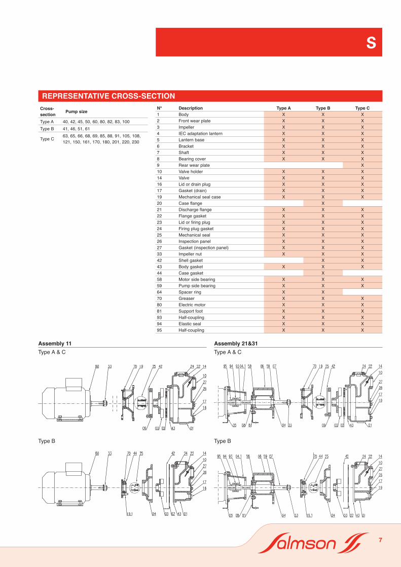
REPRESENTATIVE CROSS-SECTIONCross-section Pump size
Type A 40, 42, 45, 50, 60, 80, 82, 83, 100Type B 41, 46, 51, 61
Type C 63, 65, 66, 68, 69, 85, 88, 91, 105, 108, 121, 150, 161, 170, 180, 201, 220, 230
N° Description Type A Type B Type C1 Body X X X 2 Front wear plate X X X3 Impeller X X X4 IEC adaptation lantern X X X5 Lantern base X X X6 Bracket X X X 7 Shaft X X X 8 Bearing cover X X X 9 Rear wear plate X10 Valve holder X X X 14 Valve X X X 16 Lid or drain plug X X X 17 Gasket (drain) X X X 19 Mechanical seal case X X X 20 Case flange X21 Discharge flange X X X22 Flange gasket X X X23 Lid or firing plug X X X24 Firing plug gasket X X X25 Mechanical seal X X X26 Inspection panel X X X27 Gasket (inspection panel) X X X33 Impeller nut X X X42 Shell gasket X X43 Body gasket X X X44 Case gasket X58 Motor side bearing X X X59 Pump side bearing X X X64 Spacer ring X X70 Greaser X X X80 Electric motor X X X81 Support foot X X X93 Half-coupling X X X94 Elastic seal X X X95 Half-coupling X X X
Assembly 11Type A & C
Type B
Assembly 21&31Type A & C
Type B
S
7

ACCESSORIES
For discharge
For suction (except DN 200) For suction DN 200 only
For extension
Quick spherical connections :
Quick connections available 11/2” 2” 3” 4” DN150 DN200
Compatible pump version threaded opening special flanges
➊Male connector - threaded or flanged (according to size))
4108523 4132146 4118400 4118442 4132163 4118448
➋Suction pipe with strainer and female connector
4108524 (5m) 4132147 (5m) 4132154 (5m) 4132158 (5m) 4132164 (5m)
4071771 (6m) 4132148 (6m) 4118401 (6m) 4118443 (6m) 4132165 (6m)
Suction pipe WITHOUT strainer and with male and female connectors
4145711 (3m)
4145774 (4m)
4145712 (5m)
➌ 90° elbow with male and female connectors 4108525 4108525 4118402 4118444 4132166 4118451
➍Flat pipe for discharge (reinforced nylon PVC) with male and female connectors
4108526 (10m) 4108526 (10m) 4118404 (10m) 4132159 (5m) 4132167 (10m) 4118453 (5m)
4132149 (15m) 4132149 (15m) 4118405 (25m) 4118445 (10m) 4132168 (15m) 4118454 (10m)
4132150 (30m) 4132150 (30m) 4118446 (20m)
➎ Gasket 4108527 4108527 4118406 4118447 4132169 4118455
➏ Smooth male connector 4132144 4132151 4132155 4132160 4132170 4132173
➐ Smooth female connector 4108528 4132152 4132156 4132161 4132171 4132174
➑ Strainer without connector 4132145 4132153 4132157 4132162 4132172
Strainer with female connector 4145713
2b
8b
➊➊ ➊
➎
➎ ➎
➎ ➎ ➎ ➎
➎
➋
➐➍
➍➌
➌ 2b 8b
S
8

SUCTION PERFORMANCES
SELF-PRIMING
NPSH REQUIRED
• Suction flow limitation:The curves shown in the technical information are traced for a suction head of 1m.
When the suction head is greater the maxi-mum flow provided by the pump will be reduced as follows:- 1 m: no correction- 3 m: max. flow = ¾ of max. flow of pump- 6 m: max. flow = ½ of max. flow of pump
• Self-priming capacity:
The self-priming capacity of pumps S can reach 6m depending on the models. The firing times are given in the table opposite for water at 20°C and a minimum line length in the DN of the pump.
• Suction capacity:
The firing capacity and the suction capacity are two different concepts.
The suction capacity of the pump (NPSH) represents its ability to take out liquid when it is fired.
Pump size Speed Firing time in seconds according to the suction head. 2 3 4 5 6
S40 2900 21 47 78 135S41 2900 27 57 93 153S45 2900 12 22 35 47 62S46 2900 5 8 13 23 34S50 2900 17 29 46 83S51 2900 19 34 55 87 155S60 2900 19 29 42 56 77S61 2900 10 15 21 29 41S63 2900 7 10 14 19 33S65 1450 30 58 83 186S68 2900 9 14 19 26 38
S80(-2) 2900 36 49 62 74 95S80 2900 21 53 95 132S83 2900 14 20 26 31 39S85 1450 32 63 100 152S88 2900 4 7 11 18 26
S88 (210) 2900 5 8 11 15 20S100 2900 19 30 38 45 54S105 1450 38 69 110 167S105 2300 9 13 17 21 25
S105 T114 1450 30 62 110 189S108 2900 10 14 18 22 27S120 1450 10 18 31 50 95S150 1450 33 71 117 176S160 1450 15 26 41 63 93S170 950 28 51 85 129 181
Q m3/h ½ Qmax
6m 3m 1m(courbe de référence)
¾ Qmax Qmax
HMT
S
9
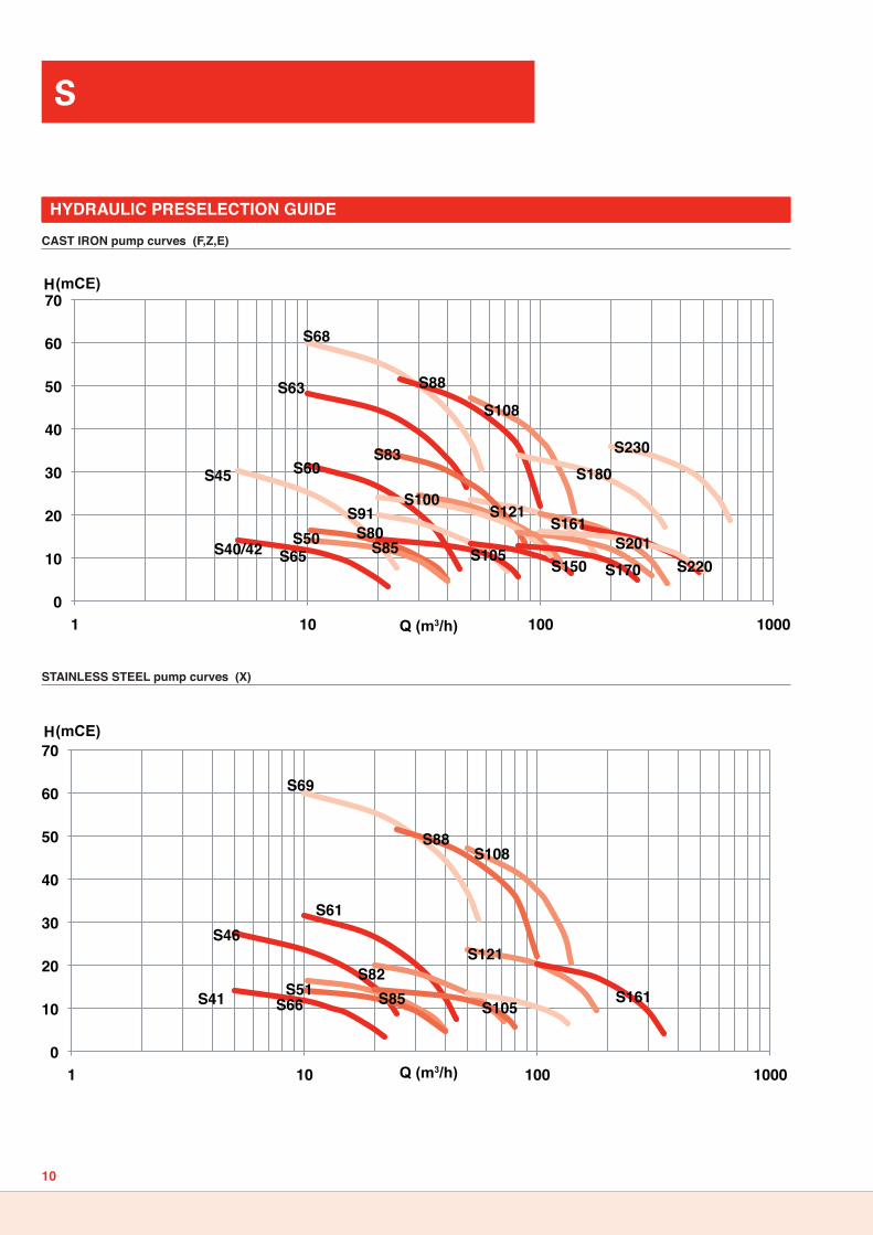
CAST IRON pump curves (F,Z,E)
STAINLESS STEEL pump curves (X)
HYDRAULIC PRESELECTION GUIDE
0
10
20
30
40
50
60
70
1 10 100 1000
S66S51 S85
S46S61
S82
S105
S121
S161
S108
S69
S88
S41
0
10
20
30
40
50
60
70
1 10 100 1000
S65S50 S85
S45 S60
S80S105
S121S161
S108
S68
S88
S40/42
S63
S83
S100S91
S180
S170S201
S150 S220
S230
Q (m3/h)
Q (m3/h)
H (mCE)
H (mCE)
S
10

HYDRAULIC PERFORMANCES
0
2
4
6
8
10
12
14
16
0 5 10 15 20 25
0,0 0,2 0,4 0,6 0,8 1,0
5 10 15 20 25
Qm3/h
Qm3/h
Qm3/h
S40-S41-S4250 Hz 2 POLES
1
3
5
7
0
0
5 10 15 20 25
NPSH
kW
m
Hm
0 0
5
10
15
20
25
30
35
40
5 10 15 20 25
S4650 Hz 2 POLES
1,5
2,0
2,5
3,0
5 10 15 20 25
12345
5 10 15 20 25
kW
NPSHm
Hm
Qm3/h
Qm3/h
Qm3/h
0
5
10
15
20
25
30
35
40
5 10 15 20 25
1,5
2,0
2,5
3,0
5 10 15 20 25
12345
5 10 15 20 25kW
NPSHm
Hm
Qm3/h
Qm3/h
Qm3/h
S4550 Hz 2 POLES
0
5
10
15
20
10 20 30 40
12345
10 20 30 40
1,0
1,5
2,0
2,5
10 20 30 40
kW
m NPSH
Hm
Qm3/h
Qm3/h
Qm3/h
S50-S5150 Hz 2 POLES
S
11

HYDRAULIC PERFORMANCES
0
10
20
30
40
10 20 30 40 50
12345
10 20 30 40 50
2,0
3,0
4,0
10 20 30 40 50
m
kW
NPSH
Hm
Qm3/h
Qm3/h
Qm3/h
S60- S6150 Hz 2 POLES
0
2
4
6
8
10
12
14
16
5 10 15 20 25 30 35 40 45
0,0 0,5 1,0 1,5 2,0 2,5
10 15 20 25 30 35 40 45
1
3
5
7
5 10 15 20 25 30 35 40 45 kW
Hm
Qm3/h
Qm3/h
Qm3/h
NPSH
m
S65 - S6650 Hz 4 POLES
10
20
30
40
50
10 20 30 40 50
4,5
5,5
6,5
10 20 30 40 50
123456
10 20 30 40 50kW
NPSHm
Hm
Qm3/h
Qm3/h
Qm3/h
S6350 Hz 2 POLES
0
10
20
30
40
50
60
70
10 20 30 40 50 60 70
0,0 2,0 4,0 6,0 8,0
10,0 12,0
10 20 30 40 50 60 70
1
3
5 7
10 20 30 40 50 60 70 kW
Hm
Qm3/h
Qm3/h
Qm3/h
NPSH
m
S68 - S6950 Hz 2 POLES
S
12

HYDRAULIC PERFORMANCES
2,0
3,0
4,0
20 40 60 80
12345
20 40 60 80
0
5
10
15
20
25
20 40 60 80m
kW
NPSH
Hm
Qm3/h
Qm3/h
Qm3/h
S80 - S8250 Hz 2 POLES
NPSH
0
5
10
15
20
10 20 30 40 50 60 70 80 90
12345
10 20 30 40 50 60 70 80 90
2,02,53,03,5
10 20 30 40 50 60 70 80 90
Hm
Qm3/h
Qm3/h
Qm3/h
kW
m
S8550 Hz 4 POLES
5,05,56,06,57,0
20 40 60 80 100
12345
20 40 60 80 100
0
10
20
30
40
20 40 60 80 100
kW
NPSHm
Hm
Qm3/h
Qm3/h
Qm3/h
S8350 Hz 2 POLES
0
5
10
15
20
25
30
20 40 60 80 100 120 140
0,0 2,0 4,0 6,0 8,0
20 40 60 80 100 120 140
1
3
5
7
20 40 60 80 100 120 140 kW
Hm
Qm3/h
Qm3/h
Qm3/h
NPSHm
S9150 Hz 4 POLES
S
13

HYDRAULIC PERFORMANCES
5
10
15
20
25
30
35
20 40 60 80 100 120 140 160
20 40 60 80 100 120 140 160
20 40 60 80 100 120 140 1606
7
8
1
2
3
m NPSH
kW
Hm
Qm3/h
Qm3/h
Qm3/h
S10050 Hz 2 POLES
10
20
30
40
50
60
40 60 80 100 120 140 160
12345
40 60 80 100 120 140 160
14,0
16,0
18,0
20,0
20 40 60 80 100 120 140 160
NPSH
Hm
Qm3/h
Qm3/h
kW
m
S108 50 Hz 2 POLES
5
7
9
11
13
15
40 60 80 100 120 140
4,0
5,0
6,0
12345
Hm
m NPSHQm3/h
40 60 80 100 120 140Qm3/h
40 60 80 100 120 140Qm3/h
kW
S10550 Hz 4 POLES
NPSHm7
9
11
13
15
17
19
21
23
25
27
40 60 80 100 120 140 160 180 200
7,08,09,0
10,011,0
40 60 80 100 120 140 160 180 200
12345
40 60 80 100 120 140 160 180 200
kW
Hm
Qm3/h
Qm3/h
Qm3/h
S12150 Hz 4 POLES
S
14

HYDRAULIC PERFORMANCES
m
kW
0
2
4
6
8
10
12
14
16
100 150 200 250
6,0
8,0
10,0
100 150 200 250
12345
100 150 200 250
NPSH
Hm
Qm3/h
Qm3/h
Qm3/h
S15050 Hz 4 POLES
0
2
4
6
8
10
12
14
16
18
0 50 100 150 200 250 300 350
0,0 2,0 4,0 6,0 8,0
10,0 12,0
0 50 100 150 200 250 300 350
1
3
5
7
0 50 100 150 200 250 300 350 kW
Hm
Qm3/h
Qm3/h
Qm3/h
NPSHm
S17050 Hz 6 POLES
0
5
10
15
20
50 100 150 200 250 300 350 400
0,0 5,0
10,0 15,0
0 50 100 150 200 250 300 350 400
kW
Hm
Qm3/h
Qm3/h
1
3
5
7
50 100 150 200 250 300 350 400 Qm3/h
NPSHm
S16150 Hz 4 POLES
m
kW
NPSH
15
20
25
30
35
40
100 150 200 250 300 350
18,022,026,030,0
100 150 200 250 300 350
12345
100 150 200 250 300 350
Hm
Qm3/h
Qm3/h
Qm3/h
S18050 Hz 6 POLES
S
15

HYDRAULIC PERFORMANCES
m
kW
5
7
9
11
13
15
17
19
100 150 200 250 300 350 400 450 500
16,0
18,0
20,0
22,0
100 150 200 250 300 350 400 450 500
12345
100 150 200 250 300 350 400 450 500
NPSH
Hm
Qm3/h
Qm3/h
Qm3/h
S20150 Hz 4 POLES
m
kW
NPSH
15
20
25
30
35
40
150 250 350 450 550 650
30,0
40,0
50,0
60,0
150 250 350 450 550 650
12345
150 250 350 450 550 650
Hm
Qm3/h
Qm3/h
Qm3/h
S23050 Hz 4 POLES
0
2
4
6
8
10
12
14
16
18
0 100 200 300 400 500 600
0,0 5,0
10,0 15,0 20,0
0 100 200 300 400 500 600
1
3
5
7
0 100 200 kW
Qm3/h
Qm3/h
Qm3/h
Hm
NPSHm
S22050 Hz 6 POLES
S
16

MONOBLOC SPACE REQUIREMENT (11)
TYPE Threaded DN
Flanged DNPN16 A1 A2 B1 B2 B3 F1 H1 H2 H3 M2 M3 N1* N3 P1 P2 R1 R3 S1 S3
40-41-42 1 1/2" 40 97 132 7 29 200 366 187 69 110 186 100 110 190 87 122 1,5 M8 945-46 1 1/2” 40 121 156 7 80 273 393 237 74 115 182 125 110 210 111 146 2 M8 950-51 2” 50 112 158 9 36 231 428 225 86 133 217 125 110 210 102 158 2 M8 960-61 2” 50 112 158 9 36 257 457 267 86 133 234 140 140 240 97 158 3 M8 963 2” 50 143 189 9,5 94 317 453 272 86 133 212 140 140 260 128 174 3 M8 965-66 2” 50 112 158 9,5 60 309 480 310 86 133 265 140 260 240 88 134 18 3 14 968-69 2” 50 112 158 9,5 60 309 597 310 86 133 246 270 260 216 88 134 18 4 14 980-82 3" 80 140 188 13 40 283 466 277 102 158 243 140 140 240 125 173 3 M8 983 3" 80 170 218 14 85 292 461 277 102 158 220 140 160 260 155 203 3 M8 985 3" 80 195 243 16 106 367 459 310 102 158 265 140 260 240 150 198 18 3 14 988 3" 80 195 243 16 106 367 576 310 102 158 246 270 260 216 150 198 18 4 14 9100 4" 100 158 225 18 50 327 616 320 127 200 246 270 260 216 153 220 18 4 14 9
S
17

BIBLOC SPACE REQUIREMENT (21)
TYPE Threaded DN
Flanged DN PN16 A1 A2 B1 B2 B3 F2 H2 H3 H5 H6 L1 M4 N4 N5 P1 P2 R4 R5 S1 R5
40-41-42 1 1/2" 40 97 132 7 29 200 311 69 110 110 207 545 337 140 180 87 122 3 3 10 1045-46 1 1/2” 40 121 156 7 80 273 324 74 115 130 257 605 349 140 200 111 146 3 3 10 1050-51 2” 50 112 158 9 36 231 359 86 133 130 245 640 384 140 200 102 158 3 3 10 1060-61 2” 50 112 158 9 36 257 424 86 133 160 295 757 458 200 230 97 158 3 4 12 1063 2” 50 143 189 9,5 94 317 419 86 133 160 300 792 458 250 230 128 174 5 4 14 1065-66 2” 50 112 158 9,5 60 309 483 86 133 160 310 816 526 200 260 88 134 3 18 12 1468-69 2” 50 112 158 9,5 60 309 535 86 133 180 330 1013 588 250 260 88 134 6 38 14 1180-82 3" 80 140 188 13 40 283 433 102 158 160 305 766 467 200 230 125 173 3 4 12 1083 3" 80 170 218 14 85 292 423 102 158 160 305 796 461 250 250 155 203 5 4 14 1085 3" 80 195 243 16 106 367 462 102 158 160 310 795 526 200 260 150 198 3 18 12 1488 3" 80 195 243 16 106 367 514 102 158 180 330 992 588 250 260 150 198 6 38 14 11100 4" 100 158 225 17,5 50 327 554 127 200 180 340 1032 588 250 260 153 220 6 38 14 11105 4" 100 228 295 17 107 349 493 127 200 180 345 866 551 250 260 193 260 5 18 14 14108 4" 100 228 295 17 107 383 596 127 200 180 345 1074 666 250 260 193 260 6 18 14 14121 4" 100 248 315 19 143 412 612 122 195 220 390 1090 676 250 295 213 280 6 18 14 14150 150 103 340 26 109 445,5 660,5 140 243 200 380 1199 725 250 295 202 340 6 18 14 14161 150 237 340 26 139 506,5 670,5 140 243 230 410 1283,5 740 250 315 202 340 6 18 14 14
S
18

SPACE REQUIREMENT ON BASE (31)
TYPE Flanged DN PN16 A1 A2 B1 B2 B6 F H1 H3 H7 L2 L3 L4 L5 N6 P1 P2 R6 S6
170 150 279 382 26 173 610 602 490 249 103 1686 250 940 502 550 229 332 53 29180 150 279 382 26 173 610 602 490 249 103 1870 250 940 502 550 229 332 53 29201 200 339 471 36 140 610 617,5 461 300 103 1855,5 250 940 596 550 294 426 53 29220 200 340 463 36 179 610 622 530 283 103 1852 250 940 583 550 290 413 53 29230 200 340 463 36 179 660 622 530 283 123 2050 290 1060 623 600 290 413 63 29
TYPE Flanged DN PN16 A1 A2 B1 B2 B6 F H1 H3 H7 L2 L3 L4 L5 N6 P1 P2 R6 S6 X
170 150 279 382 26 173 660 602 490 249 123 1826 290 1060 542 600 229 332 63 29 140180 150 279 382 26 173 660 602 490 249 123 2010 290 1060 542 600 229 332 63 29 140201 200 339 471 36 140 660 617,5 461 300 123 1995,5 290 1060 636 600 294 426 63 29 140220 200 340 463 36 179 660 622 530 283 123 1992 290 1060 623 600 290 413 63 29 140230 200 340 463 36 179 660 622 530 283 123 2190 290 1060 623 600 290 413 63 29 140
SPACE REQUIREMENT ON BASE WITH SPACER (32)
S
19

BARE SHAFT PUMP SPACE REQUIREMENT (35)
TYPE Threaded DN
Flanged DN PN16 A1 A2 B1 B2 B3 D E1 F H1 H2 H3 H4 M1 N1* N2 P1 P2 R1 R2 S1 S2 T U W
40-41-42 1 1/2" 40 97 132 7 29 200 19 40 267 187 69 110 90 202 110 80 87 122 3 M8 10 21,5 6 35
45-46 1 1/2” 40 121 156 7 80 273 19 40 270 237 74 115 110 200 110 100 111 146 3 M8 10 21,5 6 4050-51 2” 50 112 158 9 36 231 19 40 305 225 86 133 110 235 110 100 102 158 3 M8 10 21,5 6 4060-61 2” 50 112 158 9 36 257 28 60 361 267 86 133 132 273 140 125 97 158 4 M8 13 31 8 42,5
63 2” 50 143 189 9,5 94 317 28 60 336 272 86 133 132 248 140 125 128 174 4 M8 13 31 8 4365-66 2” 50 112 158 9,5 60 309 28 60 421 310 86 133 160 344 260 150 88 134 18 5 14 14 31 8 4168-69 2” 50 112 158 9,5 60 309 28 60 421 310 86 133 160 344 260 150 88 134 18 5 14 14 31 8 4180-82 3" 80 140 188 13 40 283 28 60 370 277 102 158 132 282 140 125 125 173 4 M8 13 31 8 43
83 3" 80 170 218 14 85 292 28 60 340 277 102 158 132 252 160 125 155 203 4 M8 13 31 8 4385 3" 80 195 243 16 106 367 28 60 400 310 102 158 160 344 260 150 150 198 18 5 14 14 31 8 41,588 3" 80 195 243 16 106 367 28 60 400 310 102 158 160 344 260 150 150 198 18 5 14 14 31 8 41,591 3" 80 211 259 14 135 419 32 80 491 350 97 153 200 387 295 150 175 223 18 6 14 14 35 10 60100 4" 100 158 225 18 50 327 28 60 440 320 127 200 160 344 260 150 153 220 18 5 14 14 31 8 41,5105 4" 100 228 295 17 107 349 28 60 410 345 127 200 180 344 260 150 193 260 18 5 14 14 31 8 41108 4" 100 228 295 17 107 383 32 80 487 345 127 200 180 392 260 150 193 260 18 5 14 14 35 10 50121 4" 100 248 315 19 143 412 32 80 497 390 122 195 220 392 295 150 213 280 18 6 14 14 35 10 60,5150 150 103 340 26 109 446 32 80 547 380 140 243 200 447 295 150 202 340 18 6 14 14 35 10 55161 150 237 340 26 139 507 32 80 557 410 140 243 230 457 315 150 202 340 18 6 14 14 35 10 55170 150 279 382 26 173 580 42 90 602 490 146 249 280 489 380 260 229 332 25 8 18 18 45 12 77180 150 279 382 26 173 580 42 90 602 490 146 249 280 489 380 260 229 332 25 8 18 18 45 12 77201 200 339 471 36 140 583 42 90 618 461 168 300 280 500 410 260 294 426 25 8 18 18 45 12 77220 200 340 463 36 179 642 42 90 622 530 160 283 310 509 450 260 290 413 25 8 18 18 45 12 73230 200 340 463 36 179 642 42 90 622 530 160 283 310 509 450 260 290 413 25 8 18 18 45 12 73
S
20