operation, maintenance & set-up manual · 13.2 preventative maintenance checklist form ......
TRANSCRIPT
Operation, Maintenance & Set-Up Manual ECS Membrane Processor: PMC and ISD
Part: VST ECS-CS3-310 – Three Phase VST-ECS-CS3-110 – Single Phase
Executive Orders: VR-203-E VR-204-E
Version: 1.0 ( j )
Vapor Systems Technologies, Inc. 650 Pleasant Valley Drive Springboro, Ohio 45066 937-704-9333 PH 937-704-9443 FX www.vsthose.com

VST EVR Total Balance System Solution
Page 15-2 Version 1.0(j) ARB Approved IOM 15 – Processor OM&S Manual – Executive Orders VR-203-E and VR-204-E
Table of Contents Table of Figures ........................................................................................................................................................... 5
About VST ..................................................................................................................................................................... 7
Notice ............................................................................................................................................................................ 7
Warranty ....................................................................................................................................................................... 8
Warranty Cards ............................................................................................................................................................ 9
Components and Warranties .................................................................................................................................... 10
Activating the Processor Warranty .......................................................................................................................... 11
VST Contractor Requirements .................................................................................................................................. 12
Veeder-Root Contractor Requirements .................................................................................................................... 13
Safety Icons ................................................................................................................................................................ 14
Table of Terms & Abbreviations ............................................................................................................................... 15
1 ECS Membrane Processor Overview .............................................................................................................. 16
1.1 ECS Membrane Processor Theory of Operation ........................................................................................ 16 1.2 Overview of How the Processor Operates .................................................................................................. 17 1.3 Processor Dimensions and Weight ............................................................................................................. 17 1.4 Processor Components and Their Purpose ................................................................................................ 18 1.5 Processor Auxiliary Components ................................................................................................................ 20 1.6 Processor Manuals ..................................................................................................................................... 20
2 Processor Operation ........................................................................................................................................ 26
2.1 TLS 350 Construction ................................................................................................................................. 26 2.2 Automatic Control ....................................................................................................................................... 27 2.3 Manual Control of the Processor ................................................................................................................ 28 2.4 TLS Alarms ................................................................................................................................................. 29 2.5 Thresholds and Algorithms ......................................................................................................................... 29
2.5.1 TLS-350 (PMC): Alarm Troubleshooting Summary ............................................................................................... 32 2.5.2 TLS-350 (ISD): Alarm Troubleshooting Summary ................................................................................................. 33
3 Post-Installation Power-Up Tests.................................................................................................................... 35
3.1 Post-Installation Electrical Connections ...................................................................................................... 35 3.2 Required Post-Installation Power-Up Tests ................................................................................................ 37 3.3 TLS Manual Mode ...................................................................................................................................... 39 3.4 Electrical Connection Test .......................................................................................................................... 41 3.5 Motor-Rotation Test .................................................................................................................................... 41 3.6 Heat-Trace Continuity Test ......................................................................................................................... 47

VST EVR Total Balance System Solution
Page 15-3 Version 1.0(j) ARB Approved IOM 15 – Processor OM&S Manual – Executive Orders VR-203-E and VR-204-E
3.6.1 Preparing the heat trace electrical junction box for the test: ................................................................................... 47 3.6.2 Testing the heat trace circuit ................................................................................................................................... 47
3.7 HC Sensor and HC Sentry Power Test ...................................................................................................... 48 3.7.1 Checking 24 VDC Power to the HC Sensor ........................................................................................................... 48 3.7.2 Checking 24VDC Power to the HC Sentry Module ................................................................................................. 49
3.8 Processor Leak Test: After Repair (Only) ECS Unit .................................................................................. 50 3.8.1 Purpose of the Test ................................................................................................................................................ 50 3.8.2 Preparation ............................................................................................................................................................. 50 3.8.3 Functional Test Procedures .................................................................................................................................... 50
3.9 Preparing the Processor for Field Operation .............................................................................................. 52 3.9.1 Setting the TLS-350 Threshold Values ................................................................................................................... 52 3.9.2 Processor Configuration Prior to Start Up .............................................................................................................. 52
3.10 Post-Installation Power-Up Checklist .......................................................................................................... 53 4 Processor Start-Up ........................................................................................................................................... 54
4.1 Processor Shut-Down Procedure ............................................................................................................... 55 4.1.1 Processor Shut-Down Procedure ........................................................................................................................... 55 4.1.2 HC Sensor and HC Sentry Module ......................................................................................................................... 55 4.1.3 Heat-Trace Cable ................................................................................................................................................... 55
5 Processor Maintenance ................................................................................................................................... 56
5.1 Annual System Compliance Testing ........................................................................................................... 57 5.2 Annual Inspections and Replacements ...................................................................................................... 58 5.3 Preventative Maintenance Checklist Form ................................................................................................. 59 5.4 GDF Maintenance Record .......................................................................................................................... 60
6 ECS Unit Purging Instructions Prior to Service or Maintenance ................................................................. 61
6.1 Purpose ...................................................................................................................................................... 61 6.2 Tools Required ........................................................................................................................................... 61 6.3 Preparation ................................................................................................................................................. 61 6.4 Procedures ................................................................................................................................................. 61 6.5 Post Purging Procedures ............................................................................................................................ 62 6.6 Post Service or Maintenance ...................................................................................................................... 62
7 Blower Replacement ........................................................................................................................................ 63
7.1 Blower Replacement Safety ....................................................................................................................... 63 7.2 Removing the Blower ................................................................................................................................. 63 7.3 Installing the New Blower ........................................................................................................................... 64
8 Vacuum Pump Replacement ........................................................................................................................... 66
8.1 Safety ......................................................................................................................................................... 66 8.2 Removing the Vacuum Pump ..................................................................................................................... 66 8.3 Installing the new Vacuum Pump and Vacuum Pump Motor Assembly ..................................................... 67
9 Membrane Replacement .................................................................................................................................. 70
9.1 Safety ......................................................................................................................................................... 70

VST EVR Total Balance System Solution
Page 15-4 Version 1.0(j) ARB Approved IOM 15 – Processor OM&S Manual – Executive Orders VR-203-E and VR-204-E
9.2 Removing the Membrane from the Membrane Housing ............................................................................. 70 9.3 Installing the New Membrane ..................................................................................................................... 72
10 Drive Coupling Rubber Insert Replacement .................................................................................................. 73
10.1 Safety ......................................................................................................................................................... 73 10.2 Removing the Drive Coupling Insert ........................................................................................................... 73 10.3 Installing the Drive Coupling Insert ............................................................................................................. 74
11 Heat Trace Cable Replacement ....................................................................................................................... 76
11.1 Safety ......................................................................................................................................................... 76 11.2 Removing the Heat Trace Electrical Box .................................................................................................... 76 11.3 Overview for Installing the New Heat Trace Cable ..................................................................................... 77 11.4 Steps for Installing the New Heat Trace Cable ........................................................................................... 77
12 Hydrocarbon Infrared (HC IR) Sensor Module Replacement ........................................................................ 88
12.1 Safety ......................................................................................................................................................... 88 12.2 Removing HC IR Sensor from the HC IR Sensor Module Electrical Housing ............................................. 89 12.3 Installing a New or Re-calibrated HC IR Sensor Module to the HC IR Sensor Module Electrical Housing. 91
13 Forms ................................................................................................................................................................ 93
13.1 Preventative Maintenance .......................................................................................................................... 94 13.2 Preventative Maintenance Checklist Form ................................................................................................. 95

VST EVR Total Balance System Solution
Page 15-5 Version 1.0(j) ARB Approved IOM 15 – Processor OM&S Manual – Executive Orders VR-203-E and VR-204-E
Table of Figures Figure 1: VST Registration Card ................................................................................................................................................... 9 Figure 2: ECS Membrane Processor Sticker ............................................................................................................................... 9 Figure 3: How the Processor fits into the GDF layout .............................................................................................................. 21 Figure 4: Processor Piping Diagram .......................................................................................................................................... 22 Figure 5: ECS Vent Configurations ............................................................................................................................................ 23 Figure 6: Processor Isometric Drawing (1 of 2) ........................................................................................................................ 24 Figure 7: Processor Isometric Drawing (2 of 2) ........................................................................................................................ 25 Figure 8: TLS-350 Face ................................................................................................................................................................. 26 Figure 9: Processor Run-Time Algorithm .................................................................................................................................. 31 Figure 10: Wiring the Motor Starter Relay Coil ......................................................................................................................... 36 Figure 11: ECS Piping Configuration ......................................................................................................................................... 38 Figure 12: PMC Diagnostic Menu with PMC Software .............................................................................................................. 39 Figure 13: PMC Diagnostic with ISD Software .......................................................................................................................... 40 Figure 14: Vacuum Pump: Single-Phase Motor Wiring Diagram ........................................................................................... 43 Figure 15: Vacuum Pump: Three-Phase Motor Wiring Diagram ............................................................................................ 44 Figure 16: Blower: Single-Phase Motor Wiring Diagram ........................................................................................................ 45 Figure 17: Blower: Three-Phase Motor Wiring Diagram ......................................................................................................... 46 Figure 18: Heat Trace Circuit Test .............................................................................................................................................. 47 Figure 19: HC Sentry Interface Module Front View: Power and ON/OFF Switch .................................................................. 48 Figure 20: HC Sentry Interface Module Back View: Power "ON" Light ................................................................................. 49 Figure 21: Processor Inlets & Outlets ........................................................................................................................................ 51 Figure 22: Typical Leak Check Test Fixture .............................................................................................................................. 51 Figure 23: Processor Inlets & Outlets ......................................................................................................................................... 62 Figure 24: Typical leak-check fixture .......................................................................................................................................... 62 Figure 25: Blower electrical connection conduit ...................................................................................................................... 65 Figure 26: Blower inlet and outlet tubing connections and mounting bolts .......................................................................... 65 Figure 27: Vacuum pump outlet tubing connection ................................................................................................................. 68 Figure 28: Vacuum pump inlet tubing and fittings ................................................................................................................... 68 Figure 29: Vacuum pump electrical connection / vacuum pump outlet tubing / HC sensor inlet tubing ............................ 69 Figure 30: Air outlet / vacuum pump outlet / HC sensor inlet tubing ..................................................................................... 69 Figure 31: Membrane Housing ................................................................................................................................................... 70 Figure 32: Exposed membrane with top plate removed. ......................................................................................................... 70 Figure 33: Membrane extraction tool ......................................................................................................................................... 71 Figure 34: Membrane base insert ............................................................................................................................................... 71 Figure 35: Vacuum pump with guard removed ......................................................................................................................... 73 Figure 36: Vacuum and motor assembly ................................................................................................................................... 73 Figure 37: Vacuum pump unbolted and moved away from the motor ................................................................................... 74 Figure 38: Drive coupling rubber insert ..................................................................................................................................... 75
VST EVR Total Balance System Solution
Page 15-6 Version 1.0(j) ARB Approved IOM 15 – Processor OM&S Manual – Executive Orders VR-203-E and VR-204-E
Figure 39: Termination block inside the electrical junction box ............................................................................................. 78 Figure 40: Seam to cut to remove the insulation ...................................................................................................................... 78 Figure 41: End seal kit components .......................................................................................................................................... 78 Figure 42: End seal kit installation instructions, page 1 of 2 .................................................................................................. 79 Figure 43: End seal kit installation instructions, page 2 of 2 .................................................................................................. 80 Figure 44: Prepare the new heat trace cable for installation into the end seal kit ................................................................ 81 Figure 45: Electrical junction box installation instructions, page 1 of 4 ................................................................................ 82 Figure 46: Electrical junction box installation instructions, page 2 of 4 ................................................................................ 83 Figure 47: Electrical junction box installation instructions, page 3 of 4 ................................................................................ 84 Figure 48: Electrical junction box installation instructions, page 4 of 4 ................................................................................ 85 Figure 49: End seal kit location and heat trace cable installation .......................................................................................... 86 Figure 50: Installed electrical junction box with electrical connections ................................................................................ 87 Figure 51: HC IR Sensor Module and Electrical Housing Assembly ...................................................................................... 88 Figure 52: HC IR Sensor Module 1/4" 45º tubing and fittings .................................................................................................. 89 Figure 53: HC IR Sensor Electrical Housing Circuit Board ..................................................................................................... 90 Figure 54: HC IR Sensor Electrical Housing Circuit Board Wiring Diagram .......................................................................... 90 Figure 55: HC IR sensor installation orientation ....................................................................................................................... 91

VST EVR Total Balance System Solution
Page 15-7 Version 1.0(j) ARB Approved IOM 15 – Processor OM&S Manual – Executive Orders VR-203-E and VR-204-E
About VST Vapor Systems Technologies, Inc. began in 1989 with the vision of One Company – One Integrated Solution. Today, that philosophy is still in place and getting stronger. Recognizing that a healthier environment is a need and not an option, VST has dedicated its
undivided attention to the ever-changing, stringent regulations that govern fugitive vapors at gasoline dispensing facilities (GDF). To this challenge, VST is committed to a continual R&D campaign of developing the most current, technologically advanced solutions to service not only the United States, but also the world. VST specializes in the development, engineering, and manufacturing of products that are sold into the GDF segment of the petroleum industry. The VST focus provides our customers and users with exceptional products, services, and innovative solutions for improving the fueling-station experience as well as the world’s air quality. VST’s product offering includes curb pump and vapor recovery hoses, safety breakaways, nozzles, and emission-control system Processors. The ENVIRO-LOC™ vapor-recovery product offering represents the most innovative concept in the industry for trapping fugitive vapors from the front end (vehicle refueling) to the back end (vent risers) of the GDF site.
Notice Vapor Systems Technologies, Inc. shall not be liable for errors contained herein or for incidental or consequential damages in connection with the furnishing, performance, or use of this publication. No part of this publication may be translated to another language without the prior written consent of Vapor Systems Technologies, Inc.

VST EVR Total Balance System Solution
Page 15-8 Version 1.0(j) ARB Approved IOM 15 – Processor OM&S Manual – Executive Orders VR-203-E and VR-204-E
Warranty • The warranty is conditional on whether the Processor was installed by a VST ASC Level B or a
VST Level C.
• 12-month warranty becomes effective at the time of installation. If this card is not returned, the warranty becomes effective from the date of shipment at VST.
• VST cannot be held responsible for damage to the Processor or the Processor equipment (inclusive) due to acts of nature, vandalism, or neglect.
• Membranes exposed to gasoline (liquid) due to an overfill or any other reason voids the membrane warranty.
• VST products are warranted to be free of defects in material and workmanship.
• Liability under any expressed or implied warranty is limited to replacement of the product.
• Use of VST products on non-UL Listed systems, or use which falls outside intended field of use, voids any stated or implied warranty.
• VST is not responsible for misuse of, nor improperly installed, products.
• In the event of a warranty claim, the purchaser must obtain a copy of the Return Goods Authorization (RGA) prior to returning product to insure proper processing. Return shipping charges are the responsibility of the customer.
• Warranty status will be determined within 30 days of the return of suspected items.
• VST provides for a warranty program in conjunction with VST’s exclusive serial number tracking system.
• Each VST product carries a unique serial number and warranty tracking card.
• Requests for warranty shall be through VST’s Return Goods Authorization (RGA) procedure. Call VST at 937-704-9333.
• This warranty does not cover any components exposed to contact with fuels more than 5% menthanol, 10% ethanol, 15% MTBE by volume or any exposure to M85 / E85 fuel.
VST EVR Total Balance System Solution
Page 15-9 Version 1.0(j) ARB Approved IOM 15 – Processor OM&S Manual – Executive Orders VR-203-E and VR-204-E
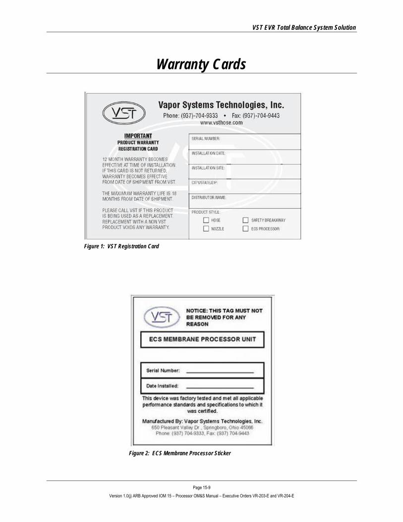
Warranty Cards
Figure 1: VST Registration Card
Figure 2: ECS Membrane Processor Sticker

VST EVR Total Balance System Solution
Page 15-10 Version 1.0(j) ARB Approved IOM 15 – Processor OM&S Manual – Executive Orders VR-203-E and VR-204-E
Components and Warranties PART # DESCRIPTION WARRANTY
5001-001 Vacuum Pump/Three-Phase Motor - Shipped with Three-Phase Processor 1 year
5001-002 Vacuum Pump/Single-Phase Motor - Shipped with Single-Phase Processor 1 year
5001-003 Vacuum Pump Drive Coupling Rubber Insert 1 year
5002-001 Circulating Blower / Three-Phase Motor - Shipped with Three-Phase Processor 1 year
5002-002 Circulating Blower / Single-Phase Motor - Shipped with Single-Phase Processor 1 year
5003-001 Check-Valve Assembly 1 year
5005-001 Membrane 1 year
5006-001 Membrane Housing, Complete 1 year
5006-011 O-Ring (2) Vertical Tube 1 year
5006-012 O-Ring (2) Base Insert 1 year
5006-013 O-Ring (2) Membrane 1 year
5007-004 Hydrocarbon Sensor 1 year
5008-001 Heat-Trace Cable 1 year
5008-002 Heat Trace Power Connection Kit 1 year
5008-003 Heat Trace End Seal Kit 1 year
5010-001 ECS Aluminum Cover 1 year
5012-100 Membrane Tubing 1 year
5012-101 Blower Inlet Tubing 1 year
5012-102 Blower Outlet Tubing 1 year
5012-103 Vacuum Pump Inlet Tubing 1 year
5012-104 Vacuum Pump Outlet Tubing 1 year
5012-105 HC Return Tubing 1 year
5012-106 HC Inlet Tubing 1 year
5012-107 Membrane Outlet Tubing 1 year
5013-001 Insulation 1 year
5015-001 HC Sentry Unit 1 year
5015-002 HC Sentry Interface Cable 1 year
VST EVR Total Balance System Solution
Page 15-11 Version 1.0(j) ARB Approved IOM 15 – Processor OM&S Manual – Executive Orders VR-203-E and VR-204-E
Activating the Processor Warranty Follow this process to activate the warranty on your Processor.
1. Make sure you have all the warranty paperwork. You should have: ► A Warranty Card – See Figure 1. ► A Post–Installation ChecklistA Post-Installation Power-Up Checklist.
2. Complete the Warranty Card ► Completely fill out the card ► Get the serial number of your Processor from the ECS Membrane Processor Sticker – See Figure 2. ► Make a copy of the card for your files. ► Place the completed, original card in an envelope for return mailing to VST.
3. Be sure the contractor who installs the Processor fills out the Post Installation Checklist. ► Go over the form to be sure the contractor has filled it out completely and signed the form. ► Make 2 copies of the form: ▪ Original goes to VST. ▪ One copy stays with the GDF. ▪ One copy goes to the contractor. ► Place the completed, original form in an envelope for return mailing to VST. ► Give one copy to the contractor. ► Place a copy in your files.
4. Be sure the contractor who performs the Processor’s initial Power-Up fills out the Post-Installation Power-Up Checklist
► Go over the form to be sure the contractor has filled it out completely and signed the form. ► Make 2 copies of the form: ▪ Original goes to VST. ▪ One copy stays with the GDF. ▪ One copy goes to the contractor. ► Place the completed, original form in an envelope for return mailing to VST. ► Give one copy to the contractor. ► Place a copy in your files.
5. Seal the envelope and mail the three forms to VST: ► The completed Warranty Card. ► The completed and signed Post-Installation Checklist. ► The completed and signed Post-Installation Power-Up Checklist. ► The VST mailing address is:
Vapor Systems Technologies, Inc. 650 Pleasant Valley Drive Springboro, OH 45066
VST EVR Total Balance System Solution
Page 15-12 Version 1.0(j) ARB Approved IOM 15 – Processor OM&S Manual – Executive Orders VR-203-E and VR-204-E
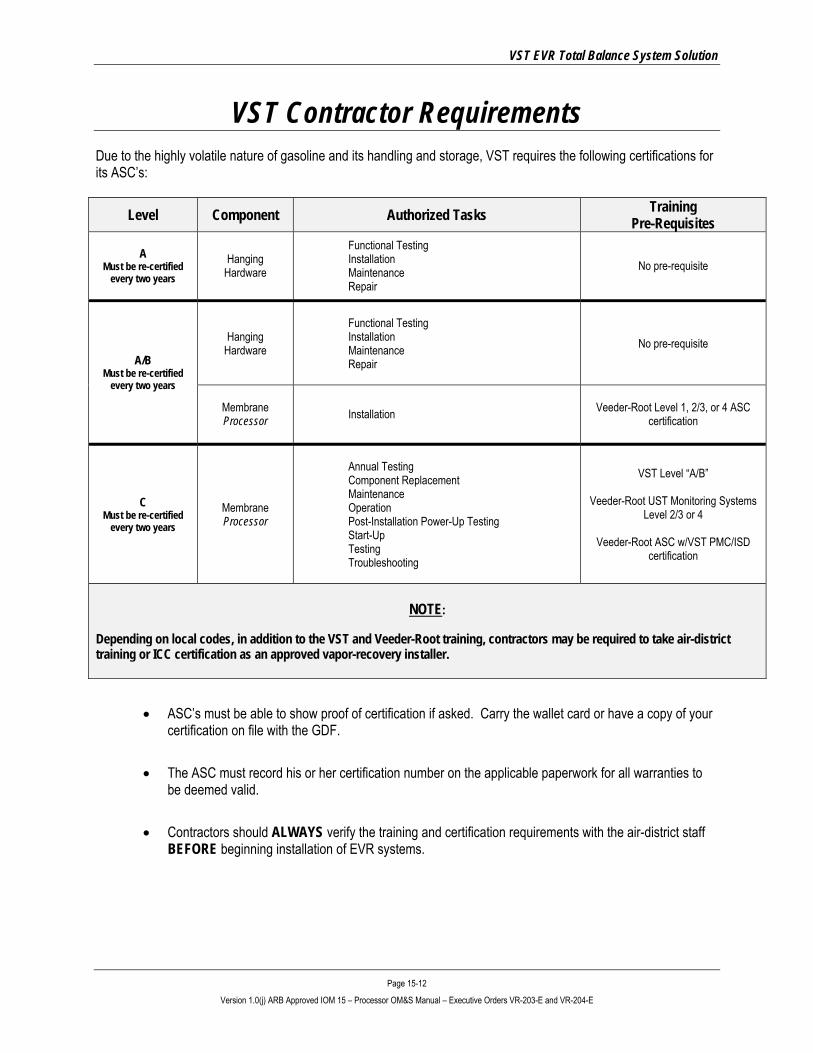
VST Contractor Requirements Due to the highly volatile nature of gasoline and its handling and storage, VST requires the following certifications for its ASC’s:
Level Component Authorized Tasks Training Pre-Requisites
A Must be re-certified
every two years Hanging
Hardware
Functional Testing Installation Maintenance Repair
No pre-requisite
A/B Must be re-certified
every two years
Hanging Hardware
Functional Testing Installation Maintenance Repair
No pre-requisite
Membrane Processor Installation Veeder-Root Level 1, 2/3, or 4 ASC
certification
C Must be re-certified
every two years Membrane Processor
Annual Testing Component Replacement Maintenance Operation Post-Installation Power-Up Testing Start-Up Testing Troubleshooting
VST Level “A/B”
Veeder-Root UST Monitoring Systems Level 2/3 or 4
Veeder-Root ASC w/VST PMC/ISD
certification
NOTE:
Depending on local codes, in addition to the VST and Veeder-Root training, contractors may be required to take air-district training or ICC certification as an approved vapor-recovery installer.
• ASC’s must be able to show proof of certification if asked. Carry the wallet card or have a copy of your certification on file with the GDF.
• The ASC must record his or her certification number on the applicable paperwork for all warranties to be deemed valid.
• Contractors should ALWAYS verify the training and certification requirements with the air-district staff BEFORE beginning installation of EVR systems.
VST EVR Total Balance System Solution
Page 15-13 Version 1.0(j) ARB Approved IOM 15 – Processor OM&S Manual – Executive Orders VR-203-E and VR-204-E
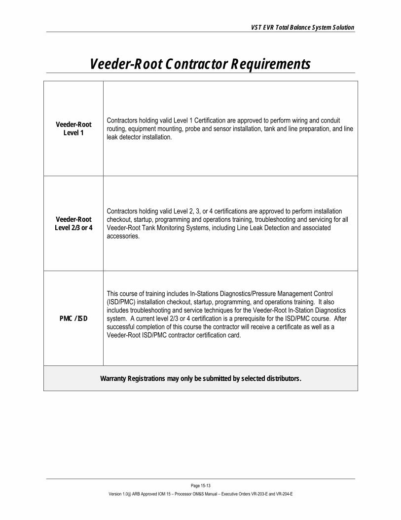
Veeder-Root Contractor Requirements
Veeder-Root Level 1
Contractors holding valid Level 1 Certification are approved to perform wiring and conduit routing, equipment mounting, probe and sensor installation, tank and line preparation, and line leak detector installation.
Veeder-Root Level 2/3 or 4
Contractors holding valid Level 2, 3, or 4 certifications are approved to perform installation checkout, startup, programming and operations training, troubleshooting and servicing for all Veeder-Root Tank Monitoring Systems, including Line Leak Detection and associated accessories.
PMC / ISD
This course of training includes In-Stations Diagnostics/Pressure Management Control (ISD/PMC) installation checkout, startup, programming, and operations training. It also includes troubleshooting and service techniques for the Veeder-Root In-Station Diagnostics system. A current level 2/3 or 4 certification is a prerequisite for the ISD/PMC course. After successful completion of this course the contractor will receive a certificate as well as a Veeder-Root ISD/PMC contractor certification card.
Warranty Registrations may only be submitted by selected distributors.

VST EVR Total Balance System Solution
Page 15-14 Version 1.0(j) ARB Approved IOM 15 – Processor OM&S Manual – Executive Orders VR-203-E and VR-204-E
Safety Icons
ELECTRICITY A potential shock hazard exists. High voltage is supplied to and exists in this device.
TURN POWER OFF Turn power off to the device and its accessories when installing and servicing the unit. Live power creates a potential spark hazard.
EXPLOSIVE Gasoline and its vapors are extremely explosive if ignited.
NO POWER TOOLS Sparks from electric power tools can ignite gasoline and its vapors.
FLAMMABLE Gasoline and its vapors are extremely flammable.
NO PEOPLE IN THE AREA Unauthorized people in the work area during installation and service of the device create a potential for personal injury.
NO SMOKING Gasoline and its vapors can be ignited by sparks and embers of burning cigarettes.
READ ALL RELATED MATERIALS Read, understand, and follow all instructions, warnings, and requirements before you begin work.
NO OPEN FLAMES Open flames from sources like lighters and matches can ignite gasoline and its vapors.
USE SAFETY BARRICADES Unauthorized people in the work area during installation and service of the device create a potential for personal injury. Therefore, always isolate your work area by using safety cones, barricades, etc.
PINCH RISK Stay clear. Keeps hands and tools away from rotating machinery and moving parts.
ROTATING MACHINERY Stay clear. Keep hands and tools away from rotating machinery.
VST EVR Total Balance System Solution
Page 15-15 Version 1.0(j) ARB Approved IOM 15 – Processor OM&S Manual – Executive Orders VR-203-E and VR-204-E
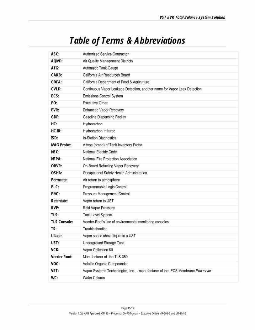
Table of Terms & Abbreviations ASC: Authorized Service Contractor AQMD: Air Quality Management Districts ATG: Automatic Tank Gauge CARB: California Air Resources Board CDFA: California Department of Food & Agriculture CVLD: Continuous Vapor Leakage Detection, another name for Vapor Leak Detection ECS: Emissions Control System EO: Executive Order EVR: Enhanced Vapor Recovery GDF: Gasoline Dispensing Facility HC: Hydrocarbon HC IR: Hydrocarbon Infrared ISD: In-Station Diagnostics MAG Probe: A type (brand) of Tank Inventory Probe NEC: National Electric Code NFPA: National Fire Protection Association ORVR: On-Board Refueling Vapor Recovery OSHA: Occupational Safety Health Administration Permeate: Air return to atmosphere PLC: Programmable Logic Control PMC: Pressure Management Control Retentate: Vapor return to UST RVP: Reid Vapor Pressure TLS: Tank Level System TLS Console: Veeder-Root’s line of environmental monitoring consoles. TS: Troubleshooting Ullage: Vapor space above liquid in a UST UST: Underground Storage Tank VCK: Vapor Collection Kit Veeder Root: Manufacturer of the TLS-350 VOC: Volatile Organic Compounds VST: Vapor Systems Technologies, Inc. - manufacturer of the ECS Membrane Processor WC: Water Column

VST EVR Total Balance System Solution
Page 15-16 Version 1.0(j) ARB Approved IOM 15 – Processor OM&S Manual – Executive Orders VR-203-E and VR-204-E
1 ECS Membrane Processor Overview
1.1 ECS Membrane Processor Theory of Operation • The VST ECS membrane Processor does not interact directly with the other balance system hardware.
It is in place to monitor and control the pressure in the UST to within limits specified by CARB. Under conditions where the GDF is operational and the balance system hardware is functioning normally, the inherent ORVR compatibility of the balance system (when using VST’s ENVIRO-LOC nozzle) will produce a predominately negative gauge pressure in the ullage space of the UST. Under these conditions the ECS membrane Processor will typically not need to operate. During periods of less activity, the GDF being shut down overnight, winter fuels being present, or other conditions that promote the pressurization of the ullage space, the ECS membrane Processor will operate as needed to control the pressure in the ullage space to an accepted level. The ECS membrane Processor will turn on at an ullage pressure of +0.20 inches of water and turn it off at a pressure of –0.20 inches of water. Currently, the ECS membrane Processor unit is monitored and controlled through the PMC or ISD software.
• The ECS membrane Processor uses a type of membrane technology to enable it to selectively separate the components in the ullage vapor mixture. Through a somewhat complex transport means, certain molecules will selectively travel in a stream from one side of the membrane to the other. This stream is referred to as the permeate stream. In this case, predominate molecules transported across the membrane will be the primary constituents of air, which are oxygen, nitrogen, and water vapor. A small amount of the hydrocarbons present in the ullage mixture will also migrate across the membrane. Typically, permeate will contain less than 3.0% hydrocarbons. The result of this activity includes, fresh air vented to atmosphere, hydrocarbon vapors returned to the UST, and UST pressurization controlled to an acceptable level.
• The process of separation by the membrane is made possible by using two pumps, one low-pressure pump which circulates the ullage vapor mixture along one side of the membrane, and one high-vacuum pump, which creates the pressure differential needed to cause the permeate transport across the membrane. These are the only moving parts in the system.

VST EVR Total Balance System Solution
Page 15-17 Version 1.0(j) ARB Approved IOM 15 – Processor OM&S Manual – Executive Orders VR-203-E and VR-204-E
1.2 Overview of How the Processor Operates • The Processor is a technology created for Gasoline Dispensing Facilities (GDF) to assist them in
reducing the number of harmful emissions released to the atmosphere through the natural occurrence of gasoline vaporization.
• The table below lists the steps that the Veeder-Root TLS 350 and the software takes to control the Processor.
1. • When the UST system pressure rises above +0.2”WC, the Processor turns ON.
2. • Through the vapor inlet pipe connection at the Processor, the VOC vapor is drawn into the suction side of the blower.
3. • The blower discharges the VOC vapor into the membrane housing.
4.
• Inside the membrane housing, the VOC vapor is separated in to two air streams:
► VOC depleted air (referred to as “air”) ► Gasoline VOC vapor
• The membrane is designed specifically for separating air from gasoline VOC vapor.
5. • A vacuum pump draws the air from the membrane housing through a check valve.
6. • A sample of the air flows through a hydrocarbon sensor to check the percent hydrocarbons.
7. • From the vacuum pump, the air is vented to atmosphere via the air return.
8. • The gasoline VOC vapor returns to the UST system via the vapor return.
9. • When the UST system pressure drops below -0.2”WC, the Processor turns OFF.
1.3 Processor Dimensions and Weight Part Number Unit Dimensions Weight
VST-ECS-CS3-110 Single-Phase L-39” x W-27” x H-43” Height includes 18” legs
385 lbs. Includes 24-lb. cover
VST-ECS-CS3-310 Three-Phase L-39” x W-27” x H-43” Height includes 18” legs
350 lbs. Includes 24-lb. cover
VST EVR Total Balance System Solution
Page 15-18 Version 1.0(j) ARB Approved IOM 15 – Processor OM&S Manual – Executive Orders VR-203-E and VR-204-E
1.4 Processor Components and Their Purpose PART # DESCRIPTION PURPOSE
5001-001 Vacuum Pump / Three-Phase Motor Shipped with Three-Phase Processor
Draws air through the membrane housing to the atmosphere.
5001-002 Vacuum Pump / Single-Phase Motor Shipped with Single-Phase Processor
5001-003 Vacuum Pump Drive Coupling Rubber Insert Drive coupling rubber insert.
5002-001 Circulating Blower / Three-Phase Motor Shipped with Three-Phase Processor
The blower circulates the vapor from the UST system through the separation membrane located inside the Processor back to the UST system.
5002-002 Circulating Blower / Single-Phase Motor Shipped with Single-Phase Processor
5003-001 Check-Valve Assembly Eliminates outside air from entering the UST’s.
5005-001 Membrane
By means of the circulating blower, the vapor from the UST system continuously flows through the membrane housing, which holds the membrane cartridge. This happens only while the Processor is running. The membrane cartridge separates the air from the VOC inlet vapor, returning a concentrated VOC stream back into the storage tank while the air is vented to the atmosphere. The membrane and housing use UL approved o-rings.
5006-001 Membrane Housing, Complete Houses the membrane cartridge.
5006-011 O-Ring (2) Vertical Tube Prevents hydrocarbons from leaking into the atmosphere.
5006-012 O-Ring (2) Base Insert
Prevents the separated air from mixing with concentrated hydrocarbons.
5006-013 O-Ring (2) Membrane
VST EVR Total Balance System Solution
Page 15-19 Version 1.0(j) ARB Approved IOM 15 – Processor OM&S Manual – Executive Orders VR-203-E and VR-204-E
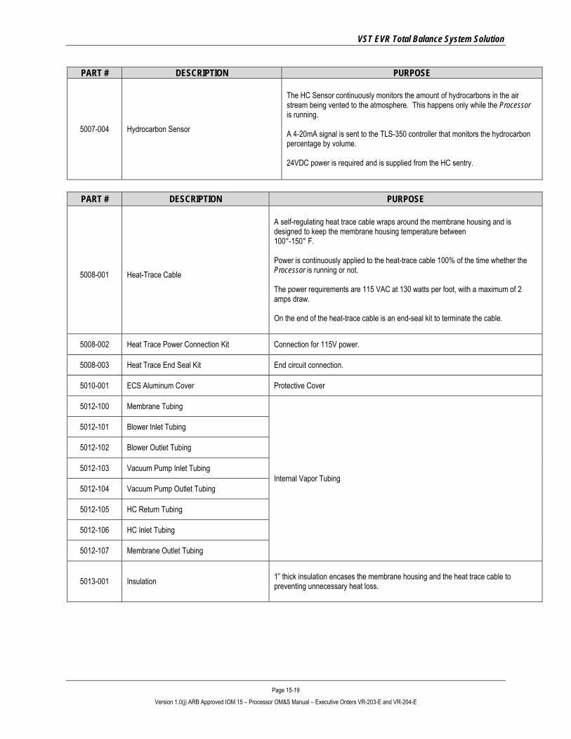
PART # DESCRIPTION PURPOSE
5007-004 Hydrocarbon Sensor
The HC Sensor continuously monitors the amount of hydrocarbons in the air stream being vented to the atmosphere. This happens only while the Processor is running. A 4-20mA signal is sent to the TLS-350 controller that monitors the hydrocarbon percentage by volume. 24VDC power is required and is supplied from the HC sentry.
PART # DESCRIPTION PURPOSE
5008-001
Heat-Trace Cable
A self-regulating heat trace cable wraps around the membrane housing and is designed to keep the membrane housing temperature between 100°-150° F. Power is continuously applied to the heat-trace cable 100% of the time whether the Processor is running or not. The power requirements are 115 VAC at 130 watts per foot, with a maximum of 2 amps draw. On the end of the heat-trace cable is an end-seal kit to terminate the cable.
5008-002 Heat Trace Power Connection Kit Connection for 115V power.
5008-003 Heat Trace End Seal Kit End circuit connection.
5010-001 ECS Aluminum Cover Protective Cover
5012-100 Membrane Tubing
Internal Vapor Tubing
5012-101 Blower Inlet Tubing
5012-102 Blower Outlet Tubing
5012-103 Vacuum Pump Inlet Tubing
5012-104 Vacuum Pump Outlet Tubing
5012-105 HC Return Tubing
5012-106 HC Inlet Tubing
5012-107 Membrane Outlet Tubing
5013-001 Insulation 1” thick insulation encases the membrane housing and the heat trace cable to preventing unnecessary heat loss.

VST EVR Total Balance System Solution
Page 15-20 Version 1.0(j) ARB Approved IOM 15 – Processor OM&S Manual – Executive Orders VR-203-E and VR-204-E
1.5 Processor Auxiliary Components
PART # COMPONENT DESCRIPTION
5015-001 HC Sentry Interface Module w/24VDC power supply
The HC Sentry module acts as an interface between the TLS and the HC sensor. 115v power is supplied to the HC sentry module, which supplies 24VDC power to the HC sensor. A 4-20 mA signal is sent from the HC sensor to the HC sentry module, which converts the signal to a proprietary code for the TLS-350.
5015-002 HC Sentry Interface Cable Connects the HC Sentry to the TLS-350.
1.6 Processor Manuals Manual # Manual Name Section
9520-001 ECS Membrane Processor with PMC/ISD: Installation Manual IOM-14
9520-002 ECS Membrane Processor with PMC/ISD: OM&S IOM-15
9514-003 ECS Membrane Processor with PMC/ISD: Troubleshooting Guide www.vsthose.com
9514-004 ECS Membrane Processor with PMC/ISD: Pre-Installation Site Survey www.vsthose.com

VST EVR Total Balance System Solution
Page 15-21 Version 1.0(j) ARB Approved IOM 15 – Processor OM&S Manual – Executive Orders VR-203-E and VR-204-E
Figure 3: How the Processor fits into the GDF layout

VST EVR Total Balance System Solution
Page 15-22 Version 1.0(j) ARB Approved IOM 15 – Processor OM&S Manual – Executive Orders VR-203-E and VR-204-E
Figure 4: Processor Piping Diagram
VST EVR Total Balance System Solution
Page 15-23 Version 1.0(j) ARB Approved IOM 15 – Processor OM&S Manual – Executive Orders VR-203-E and VR-204-E
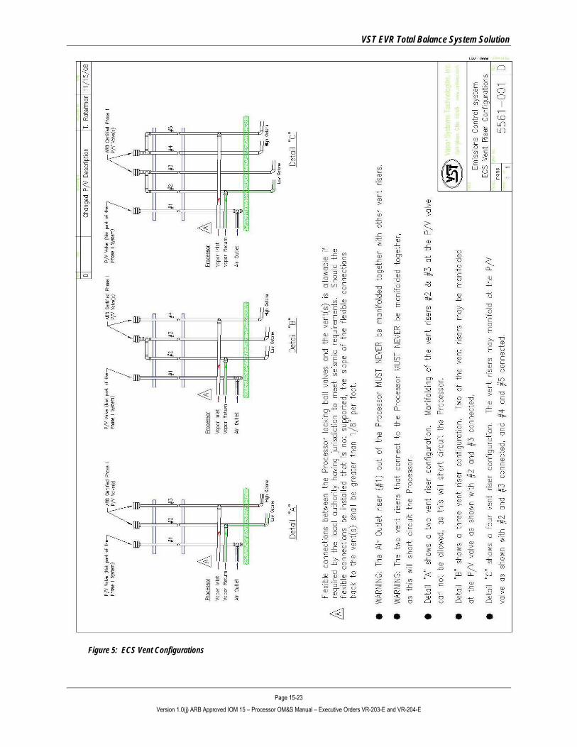
Figure 5: ECS Vent Configurations
VST EVR Total Balance System Solution
Page 15-24 Version 1.0(j) ARB Approved IOM 15 – Processor OM&S Manual – Executive Orders VR-203-E and VR-204-E
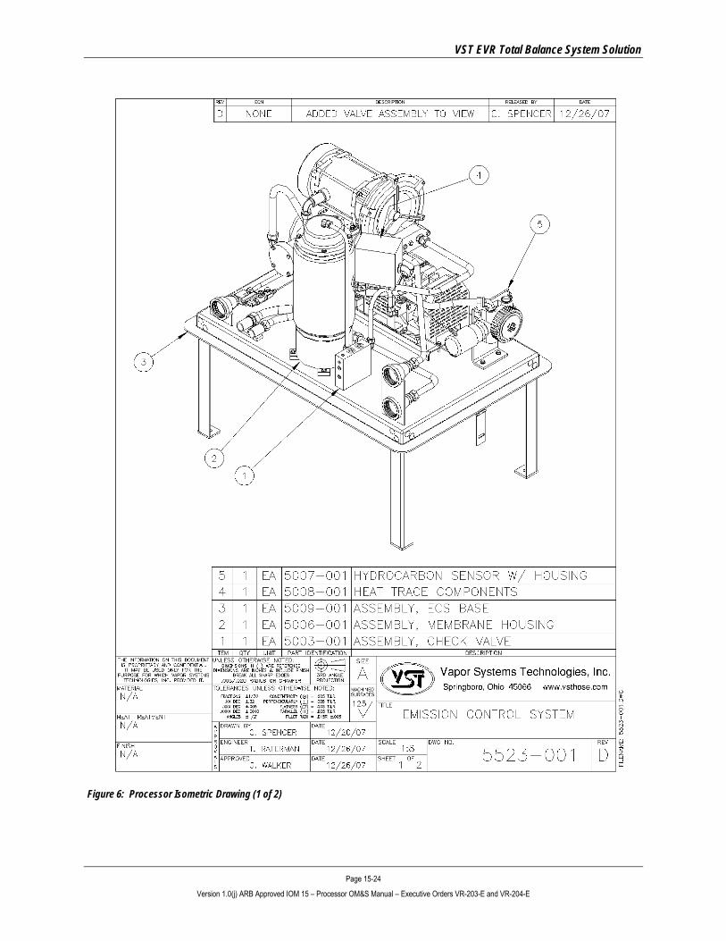
Figure 6: Processor Isometric Drawing (1 of 2)
VST EVR Total Balance System Solution
Page 15-25 Version 1.0(j) ARB Approved IOM 15 – Processor OM&S Manual – Executive Orders VR-203-E and VR-204-E
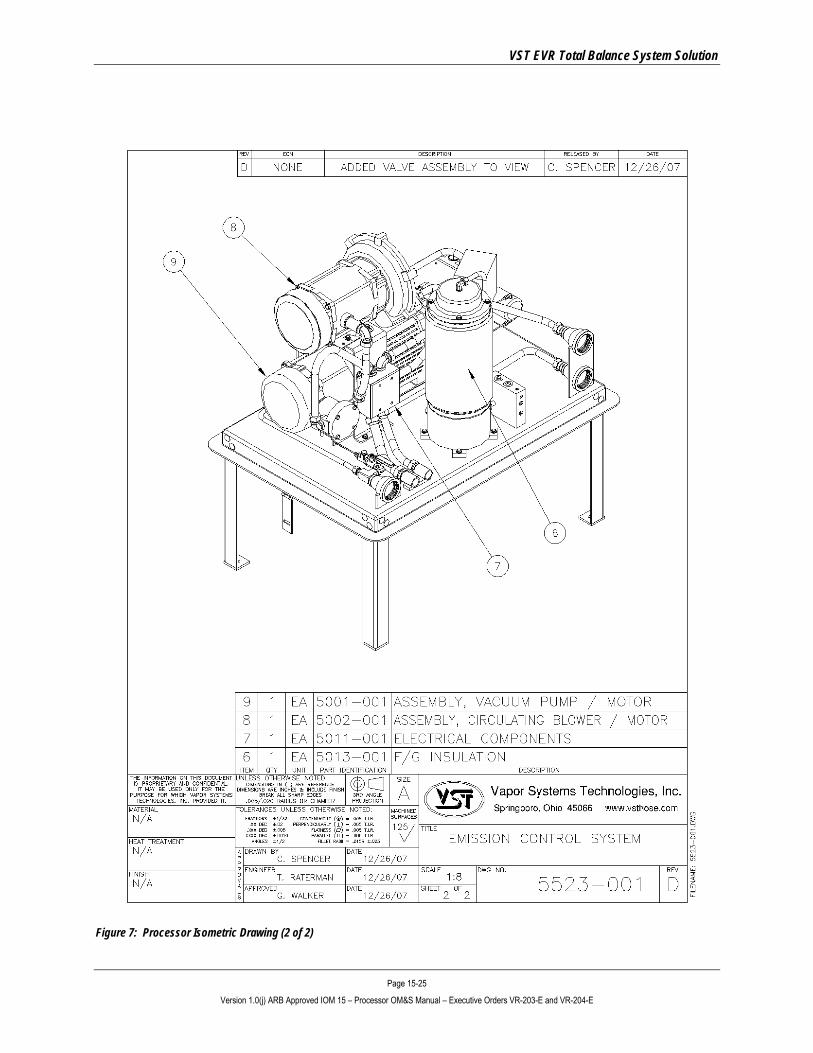
Figure 7: Processor Isometric Drawing (2 of 2)

VST EVR Total Balance System Solution
Page 15-26 Version 1.0(j) ARB Approved IOM 15 – Processor OM&S Manual – Executive Orders VR-203-E and VR-204-E
2 Processor Operation • The Veeder-Root Pressure software controls the Processor and is located within the
TLS-350 console. The TLS-350 is an automatic tank gauging, compliance, and fuel-management system.
• The TLS-350 will be configured for either PMC or ISD control software.
• Warnings and alarms are announced through the various lights on the panel as well as through a paper print-out.
2.1 TLS 350 Construction • The TLS Console is constructed with fuel compatible materials and is approved for use in GDF’s by UL
(Underwriters Laboratories, Inc.) where wetted components and materials are tested for durability and resistance to corrosion.
• The TLS Console is designed to withstand power outages by storing critical system parameters in nonvolatile memory.
• The pressure sensor (supplied by Veeder-Root) is installed inside a dispenser.
Figure 8: TLS-350 Face
VST EVR Total Balance System Solution
Page 15-27 Version 1.0(j) ARB Approved IOM 15 – Processor OM&S Manual – Executive Orders VR-203-E and VR-204-E
2.2 Automatic Control • Under automatic control, vapor pressure readings are compared to the programmed ON/OFF
thresholds to determine the appropriate Processor state. ► When the Processor is OFF and the UST pressure equals or exceeds the programmed ON vapor pressure
threshold, the Processor is turned ON and remains so until the pressure equals or is less than the programmed OFF vapor pressure threshold.
► During periods when there are no deliveries, if the Processor is ON continuously for longer than the programmed max 30 minutes runtime, the Processor is turned OFF.
► It will remain OFF for the same number of minutes programmed as max runtime minutes before turning back
ON.
► It will continue to cycle on and off until the vapor pressure drops below the low/off threshold limit.
• During a delivery, if the Processor ON time exceeds the maximum run time, the Processor will be shut OFF.
► After 3 seconds the Processor will be turned back ON if the pressure is above the high pressure threshold
limit.
► This cycle will continue until the delivery has ended or the pressure goes below the low pressure threshold and the Processor is turned OFF.
VST EVR Total Balance System Solution
Page 15-28 Version 1.0(j) ARB Approved IOM 15 – Processor OM&S Manual – Executive Orders VR-203-E and VR-204-E
At the conclusion of any testing or repairs, verify that the Processor has been set to “AUTOMATIC mode” at the TLS-350.
2.3 Manual Control of the Processor • From the PMC diagnostic menu, the Processor mode can be changed from Automatic to Manual.
• When the Processor control mode is Manual, the diagnostic menu allows the Processor to be directly turned ON and OFF. ► This feature is to support the testing functionality of the Processor or compliance testing without needing the
pressure to be at operational set points. ► This is especially useful if the vapor space has been disturbed through the course of repair or testing.
• The current vapor pressure threshold settings are available through the diagnostic menu.
• Note: If the Processor is ON and the control mode is Automatic, changing the control mode to Manual mode will turn the Processor OFF.
• This feature is to support testing functionality of the Processor without needing the pressure to be at operational set-points.
• This function is also to be used for conducting testing or at any time compliant-testing involves opening of the vapor space.
• The current vapor pressure reading will also be available through the diagnostic menu.
VST EVR Total Balance System Solution
Page 15-29 Version 1.0(j) ARB Approved IOM 15 – Processor OM&S Manual – Executive Orders VR-203-E and VR-204-E
2.4 TLS Alarms • During normal operation when the system is functioning properly and no warning or alarm conditions
exist, the “ALL FUNCTIONS NORMAL” message will appear in the system status (bottom) line of the console display.
• If a warning or alarm condition occurs, the system displays the condition type and its location.
• If more than one warning or alarm condition exists, the display will alternately flash the appropriate messages.
• The system automatically prints an alarm report showing the warning or alarm type, its location, and the date and time the warning or alarm condition occurred.
• Warning and alarm posting causes the TLS 350 to activate: ► Warning lights ► Failure-Alarm indicator lights ► Audible alarm ► Automatic strip paper printout documenting the warning or alarm
2.5 Thresholds and Algorithms • Two thresholds (high and low pressure) are used to activate and deactivate the Processor internal
TLS-350 relay.
• Three thresholds can be set via the TLS keypad or serial RS232 commands. These thresholds include: ► Vapor Processor LOW PRESSURE THRESHOLD set at -0.2” WC
▪ Maximum negative UST pressure required in order to turn OFF the Processor
► Vapor Processor HIGH PRESSURE THRESHOLD set at +0.2” WC ▪ Minimum positive UST pressure required in order to turn ON the Processor
► Vapor Processor runtime set at 30 minutes
▪ Maximum allowable runtime
• The TLS 350 control algorithm checks the current UST pressure level and turns the Processor ON and OFF according to the high and low pressure thresholds.
• All WARNINGS and ALARMS should be resolved and then followed by CLEAR TEST AFTER REPAIR (found in the TLS menu) regardless of PMC and ISD software.

VST EVR Total Balance System Solution
Page 15-30 Version 1.0(j) ARB Approved IOM 15 – Processor OM&S Manual – Executive Orders VR-203-E and VR-204-E
• The Veeder-Root Pressure Sensor (VRPS) reads every 20 seconds, and this reading is compared to the vapor-pressure thresholds to determine the Processor state, which will be either ON or OFF.
• DUE TO THE SAMPLE RATE OF 20 SECONDS, SOME DELAY OCCURS IN POSTING. THE ACTUAL VALUES DISPLAYED ON THE TLS MAY BE SLIGHTLY HIGHER THAN THE +.2”WC AND SLIGHTLY LOWER THAN THE -.2”WC SET POINTS.
• When the Processor is OFF and the high-vapor pressure threshold (+0.2”WC) is exceeded, the relay is enabled (which starts the Processor), and the relay remains enabled until the pressure drops below the low-vapor pressure (-0.2”WC) threshold.
• Automatic control is the default mode.
• The internal relay must be programmed as a VST VAPOR PROCESSOR (VP) through the TLS 350 relay setup menu.
• The Processor control algorithm will not be engaged until at least one relay of this type is detected by the TLS 350.
• Whenever the Processor runs more than 30 minutes, (whether you’re using PMC or ISD software) the Processor is automatically turned OFF. ► During this 30-minute period, the Processor will not be controlled by UST pressure and will remain OFF for
30 minutes.
• The Processor will then restart assuming the UST pressure is still above the lower threshold setting and the TLS is in the automatic controlled mode.
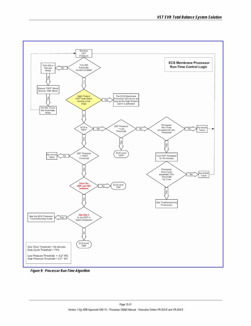
• Figure 9 shows the Processor Run-Time Algorithm.
VST EVR Total Balance System Solution
Page 15-31 Version 1.0(j) ARB Approved IOM 15 – Processor OM&S Manual – Executive Orders VR-203-E and VR-204-E
Figure 9: Processor Run-Time Algorithm
VST EVR Total Balance System Solution
Page 15-32 Version 1.0(j) ARB Approved IOM 15 – Processor OM&S Manual – Executive Orders VR-203-E and VR-204-E
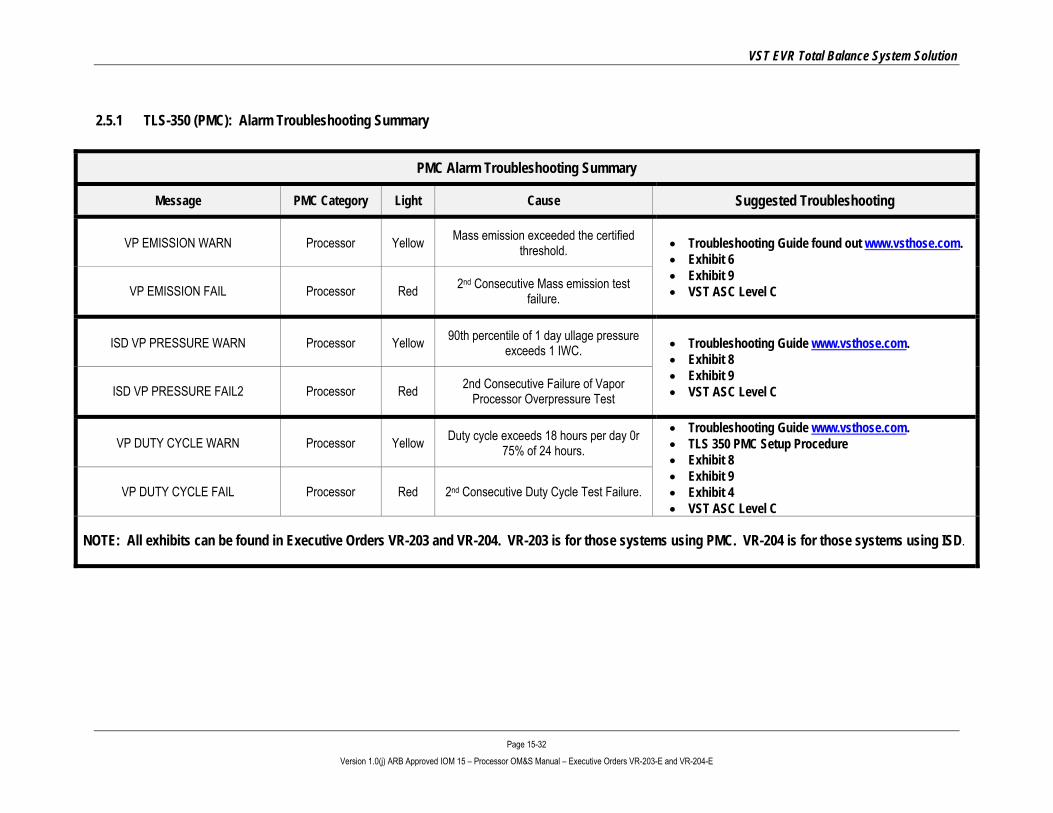
2.5.1 TLS-350 (PMC): Alarm Troubleshooting Summary
PMC Alarm Troubleshooting Summary
Message PMC Category Light Cause Suggested Troubleshooting
VP EMISSION WARN Processor Yellow Mass emission exceeded the certified threshold. • Troubleshooting Guide found out www.vsthose.com.
• Exhibit 6 • Exhibit 9 • VST ASC Level C VP EMISSION FAIL Processor Red 2nd Consecutive Mass emission test
failure.
ISD VP PRESSURE WARN Processor Yellow 90th percentile of 1 day ullage pressure exceeds 1 IWC. • Troubleshooting Guide www.vsthose.com.
• Exhibit 8 • Exhibit 9 • VST ASC Level C ISD VP PRESSURE FAIL2 Processor Red 2nd Consecutive Failure of Vapor
Processor Overpressure Test
VP DUTY CYCLE WARN Processor Yellow Duty cycle exceeds 18 hours per day 0r 75% of 24 hours.
• Troubleshooting Guide www.vsthose.com. • TLS 350 PMC Setup Procedure • Exhibit 8 • Exhibit 9 • Exhibit 4 • VST ASC Level C
VP DUTY CYCLE FAIL Processor Red 2nd Consecutive Duty Cycle Test Failure.
NOTE: All exhibits can be found in Executive Orders VR-203 and VR-204. VR-203 is for those systems using PMC. VR-204 is for those systems using ISD.
VST EVR Total Balance System Solution
Page 15-33 Version 1.0(j) ARB Approved IOM 15 – Processor OM&S Manual – Executive Orders VR-203-E and VR-204-E
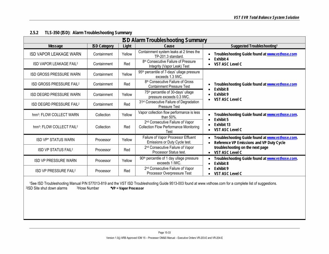
2.5.2 TLS-350 (ISD): Alarm Troubleshooting Summary ISD Alarm Troubleshooting Summary
Message ISD Category Light Cause Suggested Troubleshooting1
ISD VAPOR LEAKAGE WARN Containment Yellow Containment system leaks at 2 times the TP-201.3 standard. • Troubleshooting Guide found at www.vsthose.com
• Exhibit 4 • VST ASC Level C ISD VAPOR LEAKAGE FAIL2 Containment Red 8th Consecutive Failure of Pressure
Integrity (Vapor Leak) Test
ISD GROSS PRESSURE WARN Containment Yellow 95th percentile of 7-days’ ullage pressure exceeds 1.3 IWC.
• Troubleshooting Guide found at www.vsthose.com • Exhibit 8 • Exhibit 9 • VST ASC Level C
ISD GROSS PRESSURE FAIL2 Containment Red 8th Consecutive Failure of Gross Containment Pressure Test
ISD DEGRD PRESSURE WARN Containment Yellow 75th percentile of 30-days’ ullage pressure exceeds 0.3 IWC.
ISD DEGRD PRESSURE FAIL2 Containment Red 31st Consecutive Failure of Degradation Pressure Test
hnn3: FLOW COLLECT WARN Collection Yellow Vapor collection flow performance is less than 50%. • Troubleshooting Guide found at www.vsthose.com.
• Exhibit 5 • Exhibit 13 • VST ASC Level C hnn3: FLOW COLLECT FAIL2 Collection Red
2nd Consecutive Failure of Vapor Collection Flow Performance Monitoring
Test
ISD VP* STATUS WARN Processor Yellow Failure of Vapor Processor Effluent Emissions or Duty Cycle test.
• Troubleshooting Guide found at www.vsthose.com. • Reference VP Emissions and VP Duty Cycle
troubleshooting on the next page • VST ASC Level C ISD VP STATUS FAIL2 Processor Red 2nd Consecutive Failure of Vapor
Processor Status test.
ISD VP PRESSURE WARN Processor Yellow 90th percentile of 1 day ullage pressure exceeds 1 IWC.
• Troubleshooting Guide found at www.vsthose.com. • Exhibit 8 • Exhibit 9 • VST ASC Level C ISD VP PRESSURE FAIL2 Processor Red 2nd Consecutive Failure of Vapor
Processor Overpressure Test
1See ISD Troubleshooting Manual P/N 577013-819 and the VST ISD Troubleshooting Guide 9513-003 found at www.vsthose.com for a complete list of suggestions. 2ISD Site shut down alarms 3Hose Number *VP = Vapor Processor
VST EVR Total Balance System Solution
Page 15-34 Version 1.0(j) ARB Approved IOM 15 – Processor OM&S Manual – Executive Orders VR-203-E and VR-204-E
ISD Alarm Troubleshooting Summary Message ISD Category Light Cause Suggested Troubleshooting1
VP EMISSION WARN Processor Yellow Mass emission exceeded the certified threshold.
• Troubleshooting Guide found at www.vsthose.com. • Exhibit 6 • Exhibit 9 • VST ASC Level C VP EMISSION FAIL Processor Red 2nd Consecutive Mass emission test
failure.
VP DUTY CYCLE WARN Processor Yellow Duty cycle exceeds 18 hours per day 0r 75% of 24 hours.
• Troubleshooting Guide found at www.vsthose.com. • PMC Setup Procedure • Exhibit 8 • Exhibit 9 • Exhibit 4 • VST ASC Level C
VP DUTY CYCLE FAIL Processor Red 2nd Consecutive Duty Cycle Test Failure.
ISD SENSOR OUT WARN Self-Test Yellow Failure of Sensor Self-Test • Confirm ISD sensor & module installation / communication per VR 204 IOM Section 16, Chapter 2
• VST ASC Level C ISD SENSOR OUT FAIL Self-Test Red 8th Consecutive Failure of Sensor Self-Test
ISD SETUP WARN Self-Test Yellow Failure of Setup Test • Confirm EVR/ISD programming per VR 204 IOM Section 16
• VST ASC Level C ISD SETUP FAIL2 Self-Test Red 8th Consecutive Failure of Setup Test
1See ISD Troubleshooting Manual P/N 577013-819 and the VST ISD Troubleshooting Guide 9513-003 found at www.vsthose.com for a complete list of suggestions. 2ISD Site shut down alarms *VP=Vapor Processor
NOTE: All exhibits can be found in Executive Orders VR-203 and VR-204. VR-203 is for those systems using PMC. VR-204 is for those systems using ISD.

VST EVR Total Balance System Solution
Page 15-35 Version 1.0(j) ARB Approved IOM 15 – Processor OM&S Manual – Executive Orders VR-203-E and VR-204-E
3 Post-Installation Power-Up Tests
During post-installation testing, the Processor will use outside air, not gasoline vapor from the USTs to conduct these tests.
Close the 3 valves located on the inlet and the outlets of the Processor.
Remove the plugs on the 3 tees located on the inlet and the outlets of the Processor.
3.1 Post-Installation Electrical Connections • Prior to starting the Processor, the Motor Starter Relay Coil must be wired to the TLS-350
4-Relay Module. The Processor cannot start until this connection is made.
CAUTION: Make sure the TLS-350 is in the Manual OFF Mode prior to installing the wires. Make sure the power to the motors is OFF at the electrical panel.
• Install two 18-gauge wires that connect the Motor Starter Relay Coil to the TLS-350 4-Relay Module.
• See Figure 10 for connections to the TLS-350.
• Leaving the TLS-350 in the Manual OFF Mode, the power to the motors can be turned ON at the electrical panel.
• After the connection has been made, proceed to the Post-Installation Power-Up Tests.
• See Section 3.2.

VST EVR Total Balance System Solution
Page 15-36 Version 1.0(j) ARB Approved IOM 15 – Processor OM&S Manual – Executive Orders VR-203-E and VR-204-E
Figure 10: Wiring the Motor Starter Relay Coil
VST EVR Total Balance System Solution
Page 15-37 Version 1.0(j) ARB Approved IOM 15 – Processor OM&S Manual – Executive Orders VR-203-E and VR-204-E
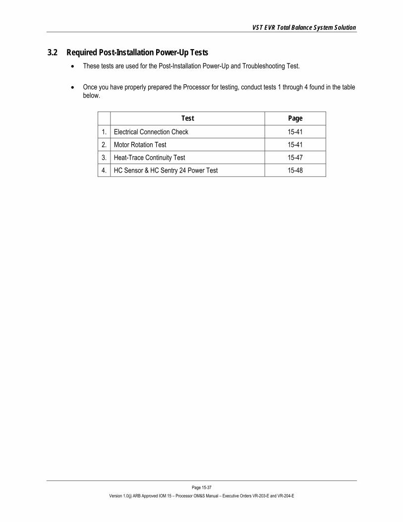
3.2 Required Post-Installation Power-Up Tests • These tests are used for the Post-Installation Power-Up and Troubleshooting Test.
• Once you have properly prepared the Processor for testing, conduct tests 1 through 4 found in the table below.
Test Page
1. Electrical Connection Check 15-41
2. Motor Rotation Test 15-41
3. Heat-Trace Continuity Test 15-47
4. HC Sensor & HC Sentry 24 Power Test 15-48

VST EVR Total Balance System Solution
Page 15-38 Version 1.0(j) ARB Approved IOM 15 – Processor OM&S Manual – Executive Orders VR-203-E and VR-204-E
Figure 11: ECS Piping Configuration

VST EVR Total Balance System Solution
Page 15-39 Version 1.0(j) ARB Approved IOM 15 – Processor OM&S Manual – Executive Orders VR-203-E and VR-204-E
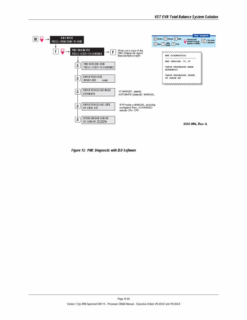
3.3 TLS Manual Mode • Follow the steps at the TLS console to put theTLS-350 in the Manual “OFF” Mode, as shown in
Figure 12 for the PMC Diagnostic Menu and Figure 13 for the ISD Diagnostic Menu.
• After the post-installation power-up tests are complete, put the Processor in the Manual “OFF” position.
• ALWAYS BE SURE TO REFER TO THE MOST RECENT VEEDER-ROOT PMC MANUAL (Manual #577013-801).
•
•
•
•
Figure 12: PMC Diagnostic Menu with PMC Software
PMC Diagnostic Menu with PMC Software (taken from Manual #577013-801 Rev. B)
VST EVR Total Balance System Solution
Page 15-40 Version 1.0(j) ARB Approved IOM 15 – Processor OM&S Manual – Executive Orders VR-203-E and VR-204-E
Figure 13: PMC Diagnostic with ISD Software

VST EVR Total Balance System Solution
Page 15-41 Version 1.0(j) ARB Approved IOM 15 – Processor OM&S Manual – Executive Orders VR-203-E and VR-204-E
C A U T I O N
Always obtain approval from the local authority having jurisdiction. Installation of the Processor must comply with (if applicable): • CARB CP-201
• VST EVR E.O.
C A U T I O N
Always obtain approval from the local authority having jurisdiction. Installation of the Processor must comply with (if applicable): • CARB CP-201
• VST EVR E.O.
• Fire Marshall
• Water Board
• Local Air Pollution
District
• ICC
• NEC
• NFPA 30 and 30A
• UL
• Any other applicable federal, state, and local codes
3.4 Electrical Connection Test • Put the TLS-350 in the Manual OFF as shown in the Diagnostic Menus
(See Figure 12 or Figure 13).
• Check all electrical and control connections prior to applying power to the Processor.
• Make sure that all connections have been made to the proper terminals and that all connections are tight. ► In the electrical room:
▪ HC Sentry 24VDC (output) / 115V power ▪ Fused disconnects ▪ Panel breaker wiring connections ▪ Starter ▪ TLS 4-relay module ▪ HC Sentry Interface Cable
► At the ECS:
▪ Blower motor ▪ Vacuum pump motor ▪ Heat trace cable ▪ HC sensor ▪ All equipment grounds
3.5 Motor-Rotation Test • The purpose of this test is to insure that the motors are rotating in the
correct direction.
• Turn the power OFF at the disconnect switch located near the Processor.
• Put the Processor in the manual ON Mode at the TLS as shown in the diagnostic menu in Figure 12 or Figure 13. ► Remove the cover from the Processor.
• Bump the power (briefly energize) the power at the disconnect switch. ► Visually check the motor rotation for the vacuum pump and blower motors to be sure they are rotating
according to the arrows that are shown on the equipment.
► The rotation of the motors can be visually checked by looking at the rotation of the fan located on the end of each motor.
CAUTION: DO NOT RUN THE PUMP(S) FOR ANY EXTENDED PERIOD OF TIME UNTIL THE PROPER ROTATION IS VERIFIED OR YOU COULD CAUSE SERIOUS DAMAGE.

VST EVR Total Balance System Solution
Page 15-42 Version 1.0(j) ARB Approved IOM 15 – Processor OM&S Manual – Executive Orders VR-203-E and VR-204-E
Motor Rotation Test, continued . . .
• If the motors are rotating in the proper direction, put the TLS in the manual OFF mode.
• If either of the motors are not rotating in the correct direction: ► Put the Processor in the manual “OFF” Mode at the TLS.
► Follow safety regulations regarding lock-out / tag-out procedures to insure power cannot be turned on to the
Processor.
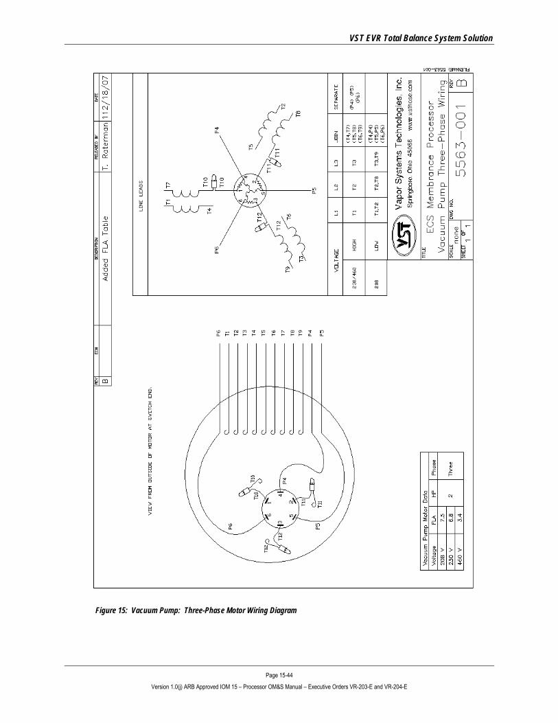
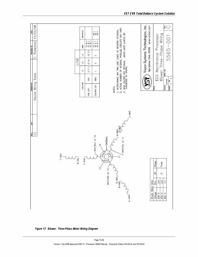
• Three-Phase Motors: ► At the motor junction box at the ECS Processor, switch any two of the three power circuits for the motor that
is not rotating in the correct direction. ► See Figure 16 and Figure 17.
• Single-Phase Motors: ► Check the wiring connection diagrams for the specific motor that is not rotating in the correct rotation and
correct as required. ► See Figure 14 and Figure 15.
• Remove the lock from the lock-out and apply power to the Processor.
• Return the Processor to the manual ON Mode at the TLS-350.
• Bump the power (briefly energize) power at the disconnect switch.
• Re-check the equipment for proper rotation.
• Return the Processor to the manual OFF mode at the TLS.
If either motor will not run, refer to the ECS Troubleshooting Guide found on the VST website at: www.vsthose.com.

VST EVR Total Balance System Solution
Page 15-43 Version 1.0(j) ARB Approved IOM 15 – Processor OM&S Manual – Executive Orders VR-203-E and VR-204-E
Figure 14: Vacuum Pump: Single-Phase Motor Wiring Diagram
VST EVR Total Balance System Solution
Page 15-44 Version 1.0(j) ARB Approved IOM 15 – Processor OM&S Manual – Executive Orders VR-203-E and VR-204-E
Figure 15: Vacuum Pump: Three-Phase Motor Wiring Diagram

VST EVR Total Balance System Solution
Page 15-45 Version 1.0(j) ARB Approved IOM 15 – Processor OM&S Manual – Executive Orders VR-203-E and VR-204-E
Figure 16: Blower: Single-Phase Motor Wiring Diagram
VST EVR Total Balance System Solution
Page 15-46 Version 1.0(j) ARB Approved IOM 15 – Processor OM&S Manual – Executive Orders VR-203-E and VR-204-E
Figure 17: Blower: Three-Phase Motor Wiring Diagram

VST EVR Total Balance System Solution
Page 15-47 Version 1.0(j) ARB Approved IOM 15 – Processor OM&S Manual – Executive Orders VR-203-E and VR-204-E
3.6 Heat-Trace Continuity Test The purpose of the Heat Trace Continuity test is to insure there is not a short or damage to the Heat Trace cable. The self-regulating heating cable provides safe and reliable heat tracing for process temperature maintenance. In electronics, a continuity test is the checking of an electric circuit to see if current flows (that it is in fact a complete circuit). A continuity test is performed by placing a small voltage (wired in series with an LED) across the chosen path. If the electron flow is inhibited by broken conductors, damaged components, or excessive resistance, the circuit is "open." Devices that can be used to perform continuity tests include multimeters or specialized continuity testers.
3.6.1 Preparing the heat trace electrical junction box for the test:
• CAUTION: Be sure to use Lockout/Tag-Out procedures when performing work on the Processor or while working on electrical components.
1. Put the Processor in the manual OFF mode at the TLS-350. 2. Trip the heat trace cable 115v circuit breaker in the electrical panel to remove the power from the heat trace
cable. 3. Remove the cover to the Processor. 4. Remove the heat trace electrical junction box cover by removing the 4 hold-down screws and lifting the
molded plastic cover off the base.
3.6.2 Testing the heat trace circuit 1. Using a multimeter or continuity tester, check the
continuity (current flow) across the heat trace circuit as shown in Figure 18.
2. Verify the circuit is complete between the positive terminal the neutral at the three-position terminal block.
3. If the red light does not come on, the heat trace circuit is open. (If electron flow is inhibited by broken conductors, damaged components, or excessive resistance, the circuit is “open.):
a) Check that all wiring connections are correct.
b) Repair/replace the heat trace cable as required to correct the problem.
4. Replace the cover on the heat trace electrical junction box using the 4-hold down screws.
5. Replace the cover on the Processor. 6. The Processor can now be put back in the
Automatic Mode at the TLS-350 provided all work is completed.
Figure 18: Heat Trace Circuit Test
VST EVR Total Balance System Solution
Page 15-48 Version 1.0(j) ARB Approved IOM 15 – Processor OM&S Manual – Executive Orders VR-203-E and VR-204-E
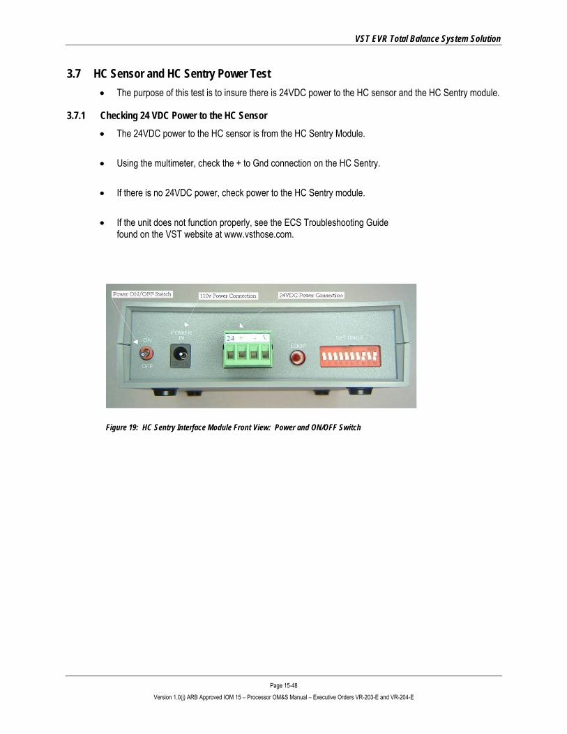
3.7 HC Sensor and HC Sentry Power Test • The purpose of this test is to insure there is 24VDC power to the HC sensor and the HC Sentry module.
3.7.1 Checking 24 VDC Power to the HC Sensor • The 24VDC power to the HC sensor is from the HC Sentry Module.
• Using the multimeter, check the + to Gnd connection on the HC Sentry.
• If there is no 24VDC power, check power to the HC Sentry module.
• If the unit does not function properly, see the ECS Troubleshooting Guide found on the VST website at www.vsthose.com.
Figure 19: HC Sentry Interface Module Front View: Power and ON/OFF Switch

VST EVR Total Balance System Solution
Page 15-49 Version 1.0(j) ARB Approved IOM 15 – Processor OM&S Manual – Executive Orders VR-203-E and VR-204-E
3.7.2 Checking 24VDC Power to the HC Sentry Module
• The HC Sentry is powered from a 115V outlet and uses a 115v/24VDC power converter, which is VST supplied.
• Check that the unit is ON.
• Check that the Power Light is ON.
• If the power light is not ON when the unit is ON: ► Check to make sure there is 115v power to the outlet.
► Check the ON switch on the HC Sentry module.
► Check that the 115v/24VDC power converter is functioning.
► If the unit does not function properly, see the ECS Troubleshooting Guide
at www.vsthose.com.
Figure 20: HC Sentry Interface Module Back View: Power "ON" Light
VST EVR Total Balance System Solution
Page 15-50 Version 1.0(j) ARB Approved IOM 15 – Processor OM&S Manual – Executive Orders VR-203-E and VR-204-E
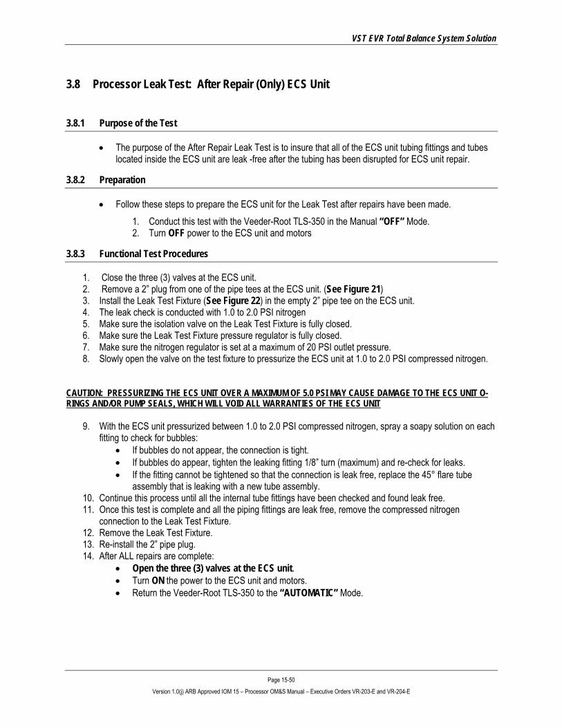
3.8 Processor Leak Test: After Repair (Only) ECS Unit
3.8.1 Purpose of the Test
• The purpose of the After Repair Leak Test is to insure that all of the ECS unit tubing fittings and tubes located inside the ECS unit are leak -free after the tubing has been disrupted for ECS unit repair.
3.8.2 Preparation
• Follow these steps to prepare the ECS unit for the Leak Test after repairs have been made. 1. Conduct this test with the Veeder-Root TLS-350 in the Manual “OFF” Mode. 2. Turn OFF power to the ECS unit and motors
3.8.3 Functional Test Procedures
1. Close the three (3) valves at the ECS unit. 2. Remove a 2” plug from one of the pipe tees at the ECS unit. (See Figure 21) 3. Install the Leak Test Fixture (See Figure 22) in the empty 2” pipe tee on the ECS unit. 4. The leak check is conducted with 1.0 to 2.0 PSI nitrogen 5. Make sure the isolation valve on the Leak Test Fixture is fully closed. 6. Make sure the Leak Test Fixture pressure regulator is fully closed. 7. Make sure the nitrogen regulator is set at a maximum of 20 PSI outlet pressure. 8. Slowly open the valve on the test fixture to pressurize the ECS unit at 1.0 to 2.0 PSI compressed nitrogen.
CAUTION: PRESSURIZING THE ECS UNIT OVER A MAXIMUM OF 5.0 PSI MAY CAUSE DAMAGE TO THE ECS UNIT O-RINGS AND/OR PUMP SEALS, WHICH WILL VOID ALL WARRANTIES OF THE ECS UNIT
9. With the ECS unit pressurized between 1.0 to 2.0 PSI compressed nitrogen, spray a soapy solution on each fitting to check for bubbles:
• If bubbles do not appear, the connection is tight. • If bubbles do appear, tighten the leaking fitting 1/8” turn (maximum) and re-check for leaks. • If the fitting cannot be tightened so that the connection is leak free, replace the 45° flare tube
assembly that is leaking with a new tube assembly. 10. Continue this process until all the internal tube fittings have been checked and found leak free. 11. Once this test is complete and all the piping fittings are leak free, remove the compressed nitrogen
connection to the Leak Test Fixture. 12. Remove the Leak Test Fixture. 13. Re-install the 2” pipe plug. 14. After ALL repairs are complete:
• Open the three (3) valves at the ECS unit. • Turn ON the power to the ECS unit and motors. • Return the Veeder-Root TLS-350 to the “AUTOMATIC” Mode.

VST EVR Total Balance System Solution
Page 15-51 Version 1.0(j) ARB Approved IOM 15 – Processor OM&S Manual – Executive Orders VR-203-E and VR-204-E
Figure 21: Processor Inlets & Outlets Figure 22: Typical Leak Check Test Fixture
Air Outlet
Vapor Inlet
Vapor Return
VST EVR Total Balance System Solution
Page 15-52 Version 1.0(j) ARB Approved IOM 15 – Processor OM&S Manual – Executive Orders VR-203-E and VR-204-E
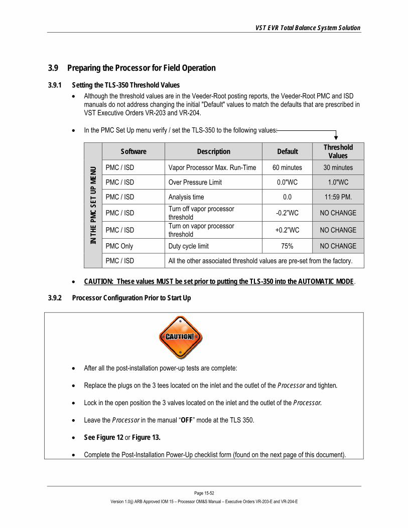
3.9 Preparing the Processor for Field Operation
3.9.1 Setting the TLS-350 Threshold Values • Although the threshold values are in the Veeder-Root posting reports, the Veeder-Root PMC and ISD
manuals do not address changing the initial "Default" values to match the defaults that are prescribed in VST Executive Orders VR-203 and VR-204.
• In the PMC Set Up menu verify / set the TLS-350 to the following values:
IN T
HE P
MC S
ET U
P ME
NU
Software Description Default Threshold Values
PMC / ISD Vapor Processor Max. Run-Time 60 minutes 30 minutes
PMC / ISD Over Pressure Limit 0.0"WC 1.0"WC
PMC / ISD Analysis time 0.0 11:59 PM.
PMC / ISD Turn off vapor processor threshold -0.2”WC NO CHANGE
PMC / ISD Turn on vapor processor threshold +0.2”WC NO CHANGE
PMC Only Duty cycle limit 75% NO CHANGE
PMC / ISD All the other associated threshold values are pre-set from the factory.
• CAUTION: These values MUST be set prior to putting the TLS-350 into the AUTOMATIC MODE.
3.9.2 Processor Configuration Prior to Start Up
• After all the post-installation power-up tests are complete:
• Replace the plugs on the 3 tees located on the inlet and the outlet of the Processor and tighten.
• Lock in the open position the 3 valves located on the inlet and the outlet of the Processor.
• Leave the Processor in the manual “OFF” mode at the TLS 350.
• See Figure 12 or Figure 13.
• Complete the Post-Installation Power-Up checklist form (found on the next page of this document).

VST EVR Total Balance System Solution
Page 15-53 Version 1.0(j) ARB Approved IOM 15 – Processor OM&S Manual – Executive Orders VR-203-E and VR-204-E
3.10 Post-Installation Power-Up Checklist

VST EVR Total Balance System Solution
Page 15-54 Version 1.0(j) ARB Approved IOM 15 – Processor OM&S Manual – Executive Orders VR-203-E and VR-204-E
4 Processor Start-Up • Use the following start-up procedure:
► When initially starting the Processor or
► When re-starting the Processor following maintenance or testing.
START-UP PROCEDURE
1. • Make sure the plugs are installed on the 3 tees at the Processor. 2. • Make sure all 3 valves are locked in the OPEN position at the Processor.
3.
• Make sure power is on to the: ▪ Heat-trace cable ▪ HC sentry ▪ HC sensor ▪ ECS vacuum pump ▪ ECS recirculation blower
4. • Make sure the pressure sensor is operational. 5. • Make sure that the GDF is vapor tight. (TP 201.3 and Exhibit 4)
6.
• After the TLS is installed and configured and all EVR equipment has been installed, the Processor can become operational.
• Put the TLS in the AUTOMATIC MODE.
• If the pressure is above +0.2” WC, the Processor will start and the auxiliary relays will close.
• If the pressure is below +0.2” WC, the Processor will not start because the UST system-pressure is below the high-pressure threshold.
NOTE: All exhibits can be found in Executive Orders VR-203 and VR-204. VR-203 is for those systems using PMC. VR-204 is for those systems using ISD.
CAUTION: Locking ball valve handles at the Processor inlet and outlet must not be removed.
VST EVR Total Balance System Solution
Page 15-55 Version 1.0(j) ARB Approved IOM 15 – Processor OM&S Manual – Executive Orders VR-203-E and VR-204-E
4.1 Processor Shut-Down Procedure CAUTION: POWER TO THE HC SENSOR AND THE HEAT TRACE CABLE MUST BE TURNED OFF INDIVIDUALLY FROM DIFFERENT POWER SOURCES. THEY DO NOT RECEIVE THEIR POWER FROM THE SAME SOURCE AS THE MOTORS.
4.1.1 Processor Shut-Down Procedure
• The Processor must be SHUT DOWN for all testing and maintenance.
• The only exception is for the “Determination of VST Processor Activation Pressure Test.”
• To turn the Processor OFF: a) Through the front panel of the TLC console, access the PMC menu. b) Select Processor MANUAL mode. c) Verify that the status is OFF. d) Remove power to the Processor by either turning OFF the breaker or by disconnecting power at the
Processor.
• To return the Processor to the AUTOMATIC mode: a) Through the front panel of the TLS console, access the PMC menu. a) Select Processor AUTOMATIC mode. b) Turn the power ON to the Processor.
4.1.2 HC Sensor and HC Sentry Module • The 115VAC/24 VDC power supply for the HC Sentry Module / HC sensor can be unplugged, which will
remove power to the HC Sensor in the Processor.
4.1.3 Heat-Trace Cable • The heat trace cable should not be turned OFF unless maintenance is performed in an area that could
cause electrical shock.
• Turn OFF power to the heat-trace cable from the 115v electrical-panel breaker.
VST EVR Total Balance System Solution
Page 15-56 Version 1.0(j) ARB Approved IOM 15 – Processor OM&S Manual – Executive Orders VR-203-E and VR-204-E
5 Processor Maintenance • The VST Emissions Control System consists of only two components having moving parts: a blower
and a vacuum pump, which do not have any scheduled maintenance for 10 years.
• The remaining components are tested, but they require maintenance only if they fail their tests: ► Heat trace cable ► HC sensor ► HC Sentry module
• Because the system continually monitors itself and notifies you of any problems or situations, it requires
very little attention.
• The table on the following page outlines the required annual inspections and tests. ► Preventative Maintenance Checklist Form ► GDF Maintenance Records

VST EVR Total Balance System Solution
Page 15-57 Version 1.0(j) ARB Approved IOM 15 – Processor OM&S Manual – Executive Orders VR-203-E and VR-204-E
5.1 Annual System Compliance Testing
Annual System Compliance Testing
Static Pressure Test: TP-201.3 Exhibit 4
Dynamic Back Pressure Test: TP-201.4
Liquid Removal Test Procedure: Exhibit 5
Hydrocarbon Sensor Verification Test: Exhibit 6
Vapor Pressure Sensor Verification Test: Exhibit 8
VST Processor Activation Test: Exhibit 9
Nozzle Bag Test Procedure: Exhibit 10
ISD Operability Test: (Flow Meter Operability Test) Exhibit 11
NOTE: All exhibits can be found in Executive Orders VR-203 and VR-204. VR-203 is for those systems using PMC. VR-204 is for those systems using ISD.
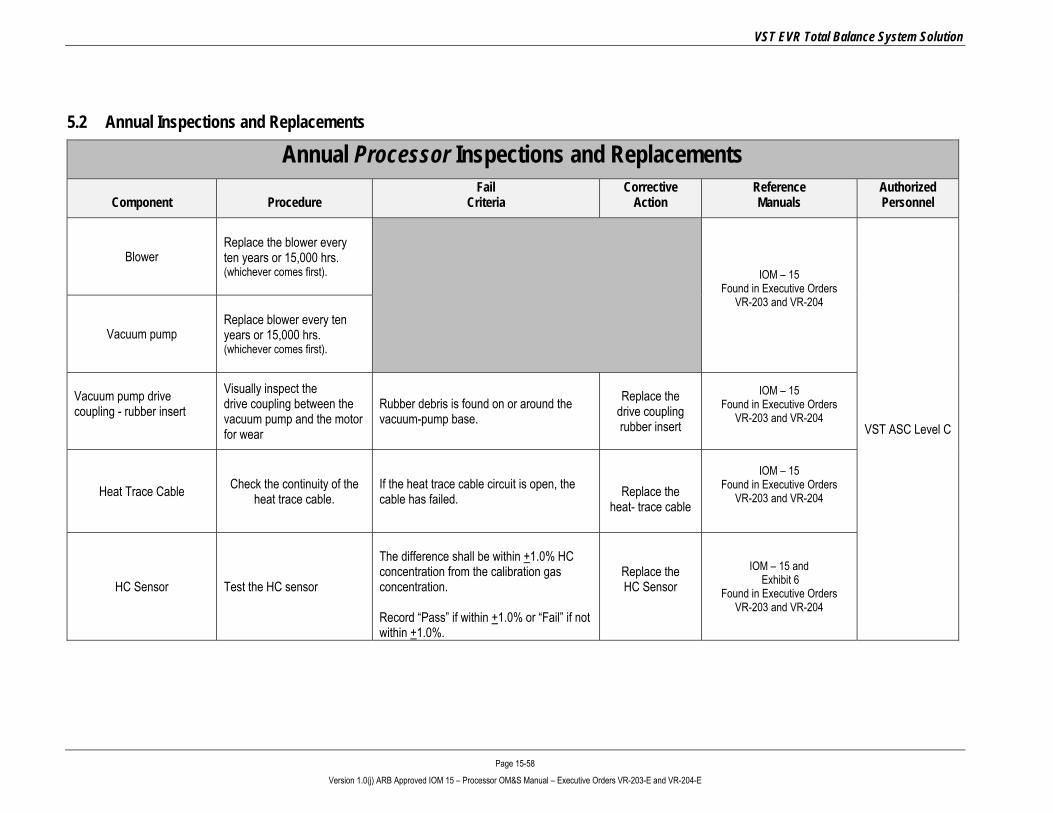
VST EVR Total Balance System Solution
Page 15-58 Version 1.0(j) ARB Approved IOM 15 – Processor OM&S Manual – Executive Orders VR-203-E and VR-204-E
5.2 Annual Inspections and Replacements
Annual Processor Inspections and Replacements
Component
Procedure
Fail Criteria
Corrective Action
Reference Manuals
Authorized Personnel
Blower Replace the blower every ten years or 15,000 hrs. (whichever comes first).
IOM – 15
Found in Executive Orders VR-203 and VR-204
VST ASC Level C
Vacuum pump Replace blower every ten years or 15,000 hrs. (whichever comes first).
Vacuum pump drive coupling - rubber insert
Visually inspect the drive coupling between the vacuum pump and the motor for wear
Rubber debris is found on or around the vacuum-pump base.
Replace the drive coupling rubber insert
IOM – 15 Found in Executive Orders
VR-203 and VR-204
Heat Trace Cable Check the continuity of the heat trace cable.
If the heat trace cable circuit is open, the cable has failed.
Replace the
heat- trace cable
IOM – 15
Found in Executive Orders VR-203 and VR-204
HC Sensor Test the HC sensor
The difference shall be within +1.0% HC concentration from the calibration gas concentration. Record “Pass” if within +1.0% or “Fail” if not within +1.0%.
Replace the HC Sensor
IOM – 15 and Exhibit 6
Found in Executive Orders VR-203 and VR-204

VST EVR Total Balance System Solution
Page 15-59 Version 1.0(j) ARB Approved IOM 15 – Processor OM&S Manual – Executive Orders VR-203-E and VR-204-E
5.3 Preventative Maintenance Checklist Form
Component Frequency Date Inspected Completed Required Action Items
PROCESSOR Yearly
• Inspect drive coupling on the vacuum pump.
[ ]
• Check the continuity of the heat trace cable.
[ ]
RECIRCULATION BLOWER
Replace every 10 years or 15,000 hours, whichever comes first.
[ ]
VACUUM PUMP
Replace every 10 years or 15,000 hours, whichever comes first.
[ ]
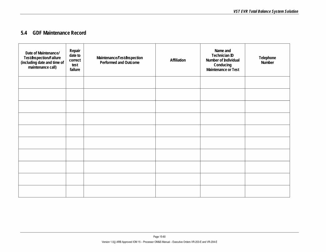
VST EVR Total Balance System Solution
Page 15-60 Version 1.0(j) ARB Approved IOM 15 – Processor OM&S Manual – Executive Orders VR-203-E and VR-204-E
5.4 GDF Maintenance Record
Date of Maintenance/ Test/Inspection/Failure
(including date and time of maintenance call)
Repair date to correct
test failure
Maintenance/Test/Inspection Performed and Outcome Affiliation
Name and Technician ID
Number of Individual Conducing
Maintenance or Test
Telephone Number
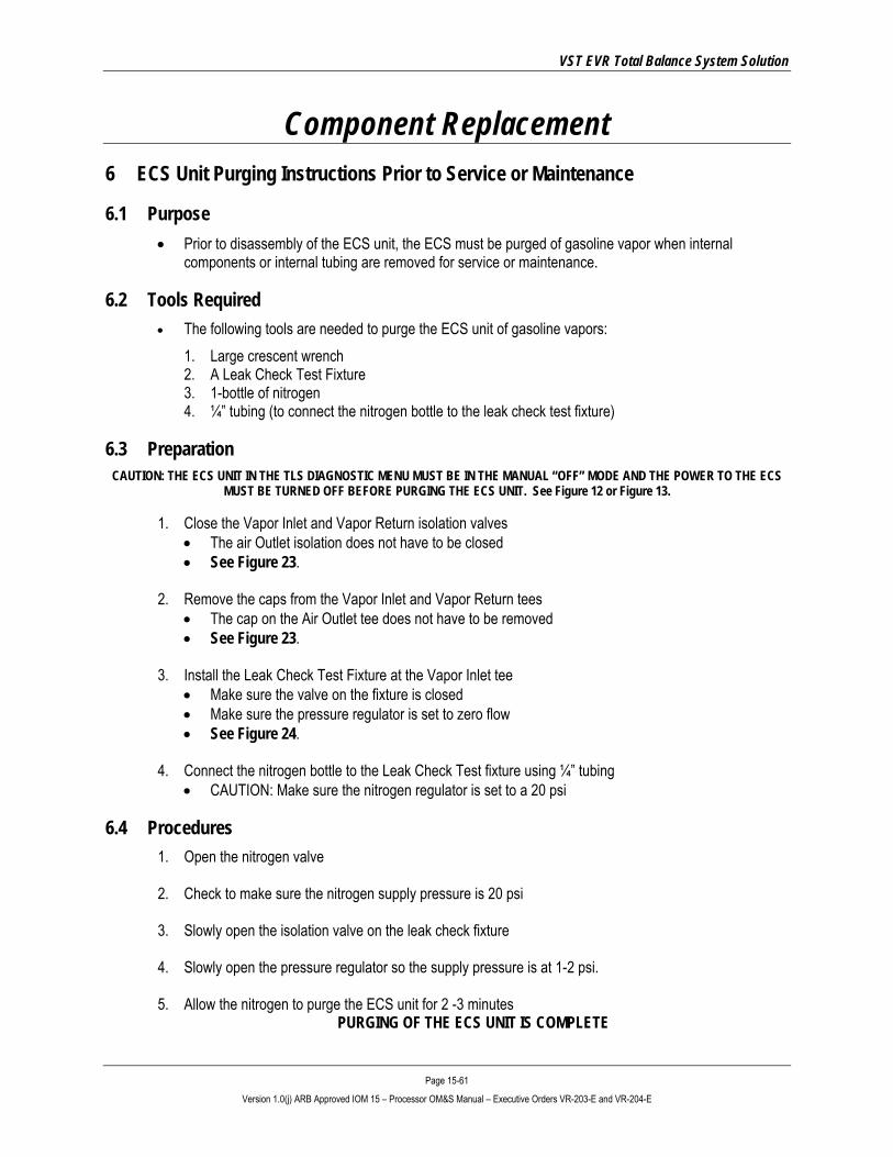
VST EVR Total Balance System Solution
Page 15-61 Version 1.0(j) ARB Approved IOM 15 – Processor OM&S Manual – Executive Orders VR-203-E and VR-204-E
Component Replacement 6 ECS Unit Purging Instructions Prior to Service or Maintenance
6.1 Purpose • Prior to disassembly of the ECS unit, the ECS must be purged of gasoline vapor when internal
components or internal tubing are removed for service or maintenance.
6.2 Tools Required • The following tools are needed to purge the ECS unit of gasoline vapors:
1. Large crescent wrench 2. A Leak Check Test Fixture 3. 1-bottle of nitrogen 4. ¼” tubing (to connect the nitrogen bottle to the leak check test fixture)
6.3 Preparation CAUTION: THE ECS UNIT IN THE TLS DIAGNOSTIC MENU MUST BE IN THE MANUAL “OFF” MODE AND THE POWER TO THE ECS
MUST BE TURNED OFF BEFORE PURGING THE ECS UNIT. See Figure 12 or Figure 13.
1. Close the Vapor Inlet and Vapor Return isolation valves • The air Outlet isolation does not have to be closed • See Figure 23.
2. Remove the caps from the Vapor Inlet and Vapor Return tees
• The cap on the Air Outlet tee does not have to be removed • See Figure 23.
3. Install the Leak Check Test Fixture at the Vapor Inlet tee
• Make sure the valve on the fixture is closed • Make sure the pressure regulator is set to zero flow • See Figure 24.
4. Connect the nitrogen bottle to the Leak Check Test fixture using ¼” tubing
• CAUTION: Make sure the nitrogen regulator is set to a 20 psi
6.4 Procedures 1. Open the nitrogen valve
2. Check to make sure the nitrogen supply pressure is 20 psi
3. Slowly open the isolation valve on the leak check fixture
4. Slowly open the pressure regulator so the supply pressure is at 1-2 psi.
5. Allow the nitrogen to purge the ECS unit for 2 -3 minutes
PURGING OF THE ECS UNIT IS COMPLETE

VST EVR Total Balance System Solution
Page 15-62 Version 1.0(j) ARB Approved IOM 15 – Processor OM&S Manual – Executive Orders VR-203-E and VR-204-E
6.5 Post Purging Procedures 1. Close the nitrogen valve 2. Remove the ¼” tubing from the nitrogen bottle to the leak check fixture 3. Close the pressure regulator valve 4. Close the isolation valve 5. Remove the leak check fixture from the ECS unit
THE ECS UNIT IS NOW READY FOR SERVICE OR MAINTENANCE
6.6 Post Service or Maintenance
1. Make sure the caps have been replaced in the tees 2. Make sure the valves on the Vapor Inlet and the Vapor Return are open 3. Make sure the ECS is set at the TLS to the AUTOMATIC MODE
Figure 23: Processor Inlets & Outlets - Figure 24: Typical leak-check fixture
2”X1/4” Bushing Isolation Valve
Pressure Regulator
Quick Disconnect
Pressure Relief Valve

VST EVR Total Balance System Solution
Page 15-63 Version 1.0(j) ARB Approved IOM 15 – Processor OM&S Manual – Executive Orders VR-203-E and VR-204-E
7 Blower Replacement
7.1 Blower Replacement Safety
Use lockout / tagout procedures prior to starting work.
7.2 Removing the Blower
1. Put the TLS 350 in the manual “OFF” mode. ▪ See Figure 12 or Figure 13.
2. Disconnect power to the blower and vacuum pump motors. Do this at both the breaker and at the disconnect
switch. The disconnect switch is located near the Processor.
3. Close the ball valves between the Processor and the vents. See Figure 23.
4. Conduct ECS Unit Purge Procedure (See Section 6 of this document).
5. Completely remove the two blower ¾” - 45° flare inlet and out tubes. ▪ See Figure 26. ▪ NOTE: The nuts on the tubing are ¾” 45º flare, use caution not to damage the flared ends on the
tubing or the threads on the nuts after removal.
6. Remove the two 45º flare inlet and outlet connection fittings from the blower.
7. Disconnect and remove the blower electrical from the motor. ▪ See Figure 25.
8. Remove (4) ¼” x ¾” mounting bolts.
▪ The 4 holes in the blower stand are tapped 1/4”. ▪ Keep the (4) ¼” bolts for reuse or replace them with new ones. ▪ CAUTION: The blower end of the blower/motor assembly is heavier than the motor end, which may
cause the blower to fall off the stand. USE CAUTION when removing the bolts.
9. Remove the blower from the stand.

VST EVR Total Balance System Solution
Page 15-64 Version 1.0(j) ARB Approved IOM 15 – Processor OM&S Manual – Executive Orders VR-203-E and VR-204-E
7.3 Installing the New Blower
1. Place the new blower on the blower stand.
2. Install and hand tighten the (4) ¼” x ¾” blower mounting bolts.
3. Install the two 45º flare inlet and outlet connection fittings into the blower.
4. Install the ¾” inlet and outlet tubing. ▪ Do not use any thread-sealing compound when assembling the 45º flare nuts. ▪ NOTE: When tightening the 45° flare nuts: Clamp the tube flare between nut and nose body of the
tube by screwing the nut on finger tight. Tighten with a wrench an additional ¼ turn for a metal-to-metal seal.
5. After the tubing is installed and the 45° flare nuts tightened, tighten the (4) mounting bolts.
6. Reconnect the electrical power wires to the blower motor.
7. Remove the lock(s) and tags from the lockout & tagout.
8. Conduct a Processor Leak Check – see Section 3.8 of this manual.
9. Open the ball valves between the Processor and the vent risers.
10. Turn ON power to the blower and vacuum pump at the breaker.
11. Put the TLS-350 in the manual ON mode.
12. Bump the power (briefly energize) the power at the disconnect switch.
13. Check the rotation of the blower motor.
14. Engage the disconnect switch.
15. After work is completed, put the TLS-350 in the AUTOMATIC mode. See Figure 12 or Figure 13.

VST EVR Total Balance System Solution
Page 15-65 Version 1.0(j) ARB Approved IOM 15 – Processor OM&S Manual – Executive Orders VR-203-E and VR-204-E
Figure 26: Blower inlet and outlet tubing connections and mounting bolts
Figure 25: Blower electrical connection conduit
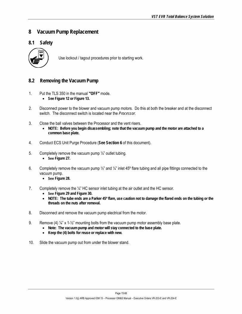
VST EVR Total Balance System Solution
Page 15-66 Version 1.0(j) ARB Approved IOM 15 – Processor OM&S Manual – Executive Orders VR-203-E and VR-204-E
8 Vacuum Pump Replacement
8.1 Safety
Use lockout / tagout procedures prior to starting work.
8.2 Removing the Vacuum Pump 1. Put the TLS 350 in the manual “OFF” mode.
• See Figure 12 or Figure 13.
2. Disconnect power to the blower and vacuum pump motors. Do this at both the breaker and at the disconnect switch. The disconnect switch is located near the Processor.
3. Close the ball valves between the Processor and the vent risers. • NOTE: Before you begin disassembling; note that the vacuum pump and the motor are attached to a
common base plate.
4. Conduct ECS Unit Purge Procedure (See Section 6 of this document).
5. Completely remove the vacuum pump ½” outlet tubing. • See Figure 27.
6. Completely remove the vacuum pump ½” and ¼” inlet 45º flare tubing and all pipe fittings connected to the
vacuum pump. • See Figure 28.
7. Completely remove the ¼” HC sensor inlet tubing at the air outlet and the HC sensor.
• See Figure 29 and Figure 30. • NOTE: The tube ends are a Parker 45º flare, use caution not to damage the flared ends on the tubing or the
threads on the nuts after removal.
8. Disconnect and remove the vacuum pump electrical from the motor.
9. Remove (4) ¼” x 1-½” mounting bolts from the vacuum pump motor assembly base plate. • Note: The vacuum pump and motor will stay connected to the base plate. • Keep the (4) bolts for reuse or replace with new.
10. Slide the vacuum pump out from under the blower stand.
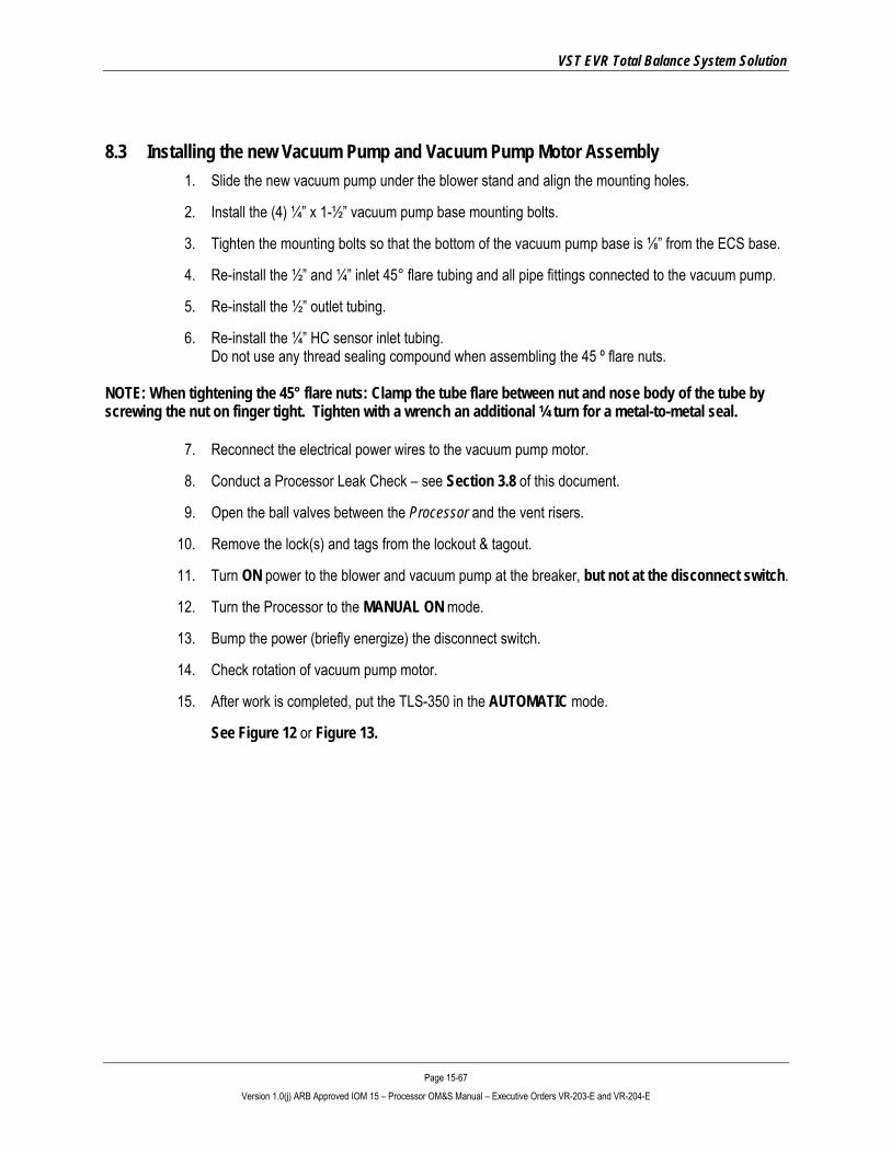
VST EVR Total Balance System Solution
Page 15-67 Version 1.0(j) ARB Approved IOM 15 – Processor OM&S Manual – Executive Orders VR-203-E and VR-204-E
8.3 Installing the new Vacuum Pump and Vacuum Pump Motor Assembly 1. Slide the new vacuum pump under the blower stand and align the mounting holes.
2. Install the (4) ¼” x 1-½” vacuum pump base mounting bolts.
3. Tighten the mounting bolts so that the bottom of the vacuum pump base is ⅛” from the ECS base.
4. Re-install the ½” and ¼” inlet 45° flare tubing and all pipe fittings connected to the vacuum pump.
5. Re-install the ½” outlet tubing.
6. Re-install the ¼” HC sensor inlet tubing. Do not use any thread sealing compound when assembling the 45 º flare nuts.
NOTE: When tightening the 45° flare nuts: Clamp the tube flare between nut and nose body of the tube by screwing the nut on finger tight. Tighten with a wrench an additional ¼ turn for a metal-to-metal seal.
7. Reconnect the electrical power wires to the vacuum pump motor.
8. Conduct a Processor Leak Check – see Section 3.8 of this document.
9. Open the ball valves between the Processor and the vent risers.
10. Remove the lock(s) and tags from the lockout & tagout.
11. Turn ON power to the blower and vacuum pump at the breaker, but not at the disconnect switch.
12. Turn the Processor to the MANUAL ON mode.
13. Bump the power (briefly energize) the disconnect switch.
14. Check rotation of vacuum pump motor.
15. After work is completed, put the TLS-350 in the AUTOMATIC mode.
See Figure 12 or Figure 13.

VST EVR Total Balance System Solution
Page 15-68 Version 1.0(j) ARB Approved IOM 15 – Processor OM&S Manual – Executive Orders VR-203-E and VR-204-E
Figure 27: Vacuum pump outlet tubing connection
Figure 28: Vacuum pump inlet tubing and fittings

VST EVR Total Balance System Solution
Page 15-69 Version 1.0(j) ARB Approved IOM 15 – Processor OM&S Manual – Executive Orders VR-203-E and VR-204-E
Figure 29: Vacuum pump electrical connection / vacuum pump outlet tubing / HC sensor inlet tubing
Figure 30: Air outlet / vacuum pump outlet / HC sensor inlet tubing

VST EVR Total Balance System Solution
Page 15-70 Version 1.0(j) ARB Approved IOM 15 – Processor OM&S Manual – Executive Orders VR-203-E and VR-204-E
9 Membrane Replacement
9.1 Safety
Use lockout / tagout procedures prior to starting work.
9.2 Removing the Membrane from the Membrane Housing
1. Put the TLS 350 in the manual “OFF” mode. See Figure 12 or Figure 13.
2. At the breaker and at the disconnect switch, disconnect power to the heat trace cable, the vacuum pump, and the blower.
3. Close the ball valves between the Processor and the vent risers.
4. Conduct ECS Unit Purge Procedure (See Section 6 of this document).
5. Disconnect and remove the ½” 45º flare tubing from the top and side of the membrane housing: See Figure 31. NOTE: The nuts on the tubing are ¾” 45° flare. Use caution not to damage the flared ends on the tubing or the threads on the nuts after removal.
6. Remove the (4) ¼” bolts from the top plate (on top of the membrane housing).
7. Keep the (4) bolts/washers/lock washers for reuse.
8. Remove the top plate. A small lever may have to be used to gently pry the top plate off the membrane housing. The top plate seals against the vertical tube with an o-ring. Use caution when removing the top plate. The membrane is now exposed. See Figure 32.
Continued next page . . .
Figure 31: Membrane Housing
Figure 32: Exposed membrane with top plate removed.

VST EVR Total Balance System Solution
Page 15-71 Version 1.0(j) ARB Approved IOM 15 – Processor OM&S Manual – Executive Orders VR-203-E and VR-204-E
9. Gently screw the membrane extraction tool into the top of the membrane. Screw the extraction tool into the membrane until the threads bottom out. See Figure 33.
CAUTION: Do not over tighten the extraction tool when screwing into the membrane. 10. Gently move the extraction tool side-to-side while
pulling up with moderate force until the membrane becomes loose. CAUTION: Do not use excessive force or a twisting action to remove the membrane as these items may cause damage to the membrane epoxy potting. There are two o-rings on the inside bottom of the vertical tube causing resistance in removing the membrane An aluminum insert (Figure 34) may still be attached to the bottom of the membrane or will stay in the membrane-housing base. DO NOT LOSE THE INSERT AS IT WILL BE NEEDED TO COMPLETE THE MEMBRANE INSTALLATION AND MAKE THE MEMBRANE OPERATION FUNCTIONAL.
11. Remove the extraction tool from the membrane.
12. Remove and discard the (4) o-rings: (2) O-rings on the membrane (2) O-rings on the base insert Keep the vertical tube top o-ring for re-use.
Figure 33: Membrane extraction tool
Figure 34: Membrane base insert

VST EVR Total Balance System Solution
Page 15-72 Version 1.0(j) ARB Approved IOM 15 – Processor OM&S Manual – Executive Orders VR-203-E and VR-204-E
9.3 Installing the New Membrane
1. Install (4) new O-rings: (2) O-rings on the membrane (VST Part #5006-012). (2) O-rings on the base insert (VST Part #5006-013).
2. Use only silicon grease (not hydrocarbon-based grease) on the o-rings prior to installation. Hydrocarbon-based grease or lubricant will emit hydrocarbon vapors, which will be measured by the HC sensor and will cause inaccurate gas-level readings.
3. With (2) new o-rings on the “insert” installed, place the “insert” into the bottom of the base as orientated in Figure 34.
4. With the (2) membrane o-rings installed, place the membrane into the membrane housing. Apply a moderate downward force with a mild side-to-side action to seat the membrane in the membrane base.
5. Install the existing top vertical tube o-ring (re-lubricated). Install the top plate. • The top plate will seat on the vertical tube o-ring while bolting the top plate in place. • DO NOT USE FORCE TO SEAT THE TOP PLATE.
6. Install the (4) ¼” bolts/washers/lock washers in the top plate/retaining ring to secure the top plate.
7. Tighten the (4) bolts to 85 in-lbs in a cross-pattern using 20%, 40%, 60%, 80%, 90%, 100% of torque.
• This cross-pattern torque procedure will evenly seat the top plate to the vertical tube.
8. Re-install the ½” 45° flare tubing from the top/side of the membrane housing. • Note: When tightening the 45° flare nuts: Clamp the tube flare between nut and nose body of the tube by
screwing the nut on finger tight. Tighten with a wench an additional ¼ turn for a metal-to-metal seal.
9. Perform a Processor Leak Test. See Section 3.8.
10. Open the ball valves between the Processor and the vent risers.
11. Remove the lock(s) and tags from the lockout & tagout.
12. Turn ON power to the heat trace, blower, and vacuum pump.
13. After work is completed, put the TLS-350 in the AUTOMATIC mode. See Figure 12 or Figure 13.

VST EVR Total Balance System Solution
Page 15-73 Version 1.0(j) ARB Approved IOM 15 – Processor OM&S Manual – Executive Orders VR-203-E and VR-204-E
10 Drive Coupling Rubber Insert Replacement • NOTE: The drive coupling rubber insert replacement is done with the vacuum pump and motor
assembly still attached to the ECS base.
10.1 Safety
Use lockout / tagout procedures prior to starting work.
10.2 Removing the Drive Coupling Insert 1. Prior to starting work, put the TLS-350 in the Manual
OFF mode. • See Figure 12
or Figure 13
2. Close the ball valves between the Processor and the vent risers.
3. At the disconnect switch and at the breaker, disconnect the power to the blower and vacuum pump motors.
4. Conduct ECS Unit Purge Procedure (See Section 6 of this document).
5. With the vacuum pump and motor assembly in-place on the ECS base, remove the drive coupling guard and the pump fan guard.
• See Figures 36-37. 6. Completely remove the vacuum pump ½” outlet
tubing. • See Figure 27.
7. Completely remove the vacuum pump ½” and ¼” inlet 45º flare tubing and all pipe fittings connected to the vacuum pump. See Figure 29.
8. Completely remove the ¼” HC sensor inlet tubing at the air outlet and the HC sensor.
• See Figure 52. • NOTE: The tube ends are a Parker 45º
flare, use caution not to damage the flared ends on the tubing or the threads on the nuts after removal.
Continued next page. . .
Figure 35: Vacuum pump with guard removed
Figure 36: Vacuum and motor assembly
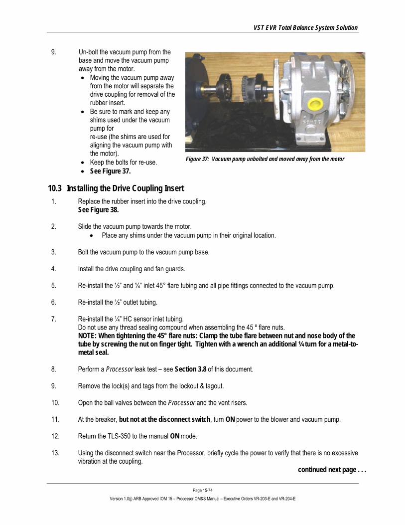
VST EVR Total Balance System Solution
Page 15-74 Version 1.0(j) ARB Approved IOM 15 – Processor OM&S Manual – Executive Orders VR-203-E and VR-204-E
9. Un-bolt the vacuum pump from the base and move the vacuum pump away from the motor. • Moving the vacuum pump away
from the motor will separate the drive coupling for removal of the rubber insert.
• Be sure to mark and keep any shims used under the vacuum pump for re-use (the shims are used for aligning the vacuum pump with the motor).
• Keep the bolts for re-use. • See Figure 37.
10.3 Installing the Drive Coupling Insert 1. Replace the rubber insert into the drive coupling.
See Figure 38.
2. Slide the vacuum pump towards the motor. • Place any shims under the vacuum pump in their original location.
3. Bolt the vacuum pump to the vacuum pump base.
4. Install the drive coupling and fan guards.
5. Re-install the ½” and ¼” inlet 45° flare tubing and all pipe fittings connected to the vacuum pump.
6. Re-install the ½” outlet tubing.
7. Re-install the ¼” HC sensor inlet tubing.
Do not use any thread sealing compound when assembling the 45 º flare nuts. NOTE: When tightening the 45° flare nuts: Clamp the tube flare between nut and nose body of the tube by screwing the nut on finger tight. Tighten with a wrench an additional ¼ turn for a metal-to-metal seal.
8. Perform a Processor leak test – see Section 3.8 of this document.
9. Remove the lock(s) and tags from the lockout & tagout.
10. Open the ball valves between the Processor and the vent risers.
11. At the breaker, but not at the disconnect switch, turn ON power to the blower and vacuum pump.
12. Return the TLS-350 to the manual ON mode.
13. Using the disconnect switch near the Processor, briefly cycle the power to verify that there is no excessive vibration at the coupling.
continued next page . . .
Figure 37: Vacuum pump unbolted and moved away from the motor

VST EVR Total Balance System Solution
Page 15-75 Version 1.0(j) ARB Approved IOM 15 – Processor OM&S Manual – Executive Orders VR-203-E and VR-204-E
15. After work is completed, put the TLS-350 in the AUTOMATIC mode and engage the disconnect. See Figures 12 or 13.
Figure 38: Drive coupling rubber insert

VST EVR Total Balance System Solution
Page 15-76 Version 1.0(j) ARB Approved IOM 15 – Processor OM&S Manual – Executive Orders VR-203-E and VR-204-E
11 Heat Trace Cable Replacement
11.1 Safety
Use lockout / tagout procedures prior to starting work. Disconnect electricity to the Processor.
11.2 Removing the Heat Trace Electrical Box 1. Prior to starting work, put the TLS-350 in the Manual “OFF” mode
• See Figure 12 or 13. • Remove power to the Processor by either turning OFF the breaker or by disconnecting power at
the Processor.
2. At the breaker, disconnect power to the heat trace cable.
3. Remove the entire heat trace electrical box from the ¾” tubing.
4. Disconnect and remove the heat trace cable from inside the electrical junction box. • Remove the top cover from the electrical junction box (be sure to keep the screws for reuse). • Remove the 115V and ground wires from the terminal block located inside the electrical junction
box. • See Figure 39. • Remove the bottom plate (be sure to keep the screws for reuse). • Pull the heat trace cable out of the electrical box and bottom plate (be sure keep the rubber
grommet for reuse).
5. Completely remove the 1” thick F/G insulation from the membrane housing. • Cutting on the insulation seam, remove the insulation (with the aluminum tape attached) in one
piece and save for reuse. • See Figure 40.
6. Peel the aluminum tape off the heat trace cable and discard.
• This will expose the heat trace cable and end seal kit.
7. Disassemble the seal kit and remove the heat trace cable. • Retain the end seal kit parts for re-use.

VST EVR Total Balance System Solution
Page 15-77 Version 1.0(j) ARB Approved IOM 15 – Processor OM&S Manual – Executive Orders VR-203-E and VR-204-E
11.3 Overview for Installing the New Heat Trace Cable 1. VST has found that making both the end seal kit and electrical junction box connection first to the heat
trace cable works the best.
2. After both connections are made to the heat trace cable, attach the electrical junction box to the ¾” tube.
3. After the electrical junction box is attached to the ¾” tube, wrap the heat trace cable around the vertical tube starting at the bottom and wrapping towards the top, applying aluminum tape on each revolution.
4. The last step is to secure the end seal kit to the vertical tube.
11.4 Steps for Installing the New Heat Trace Cable 1. Install the end seal kit on the heat trace cable:
• Using a multimeter, check the heat trace cable electrical circuit continuity at the electrical junction box to insure the circuit is complete and is not in a ground fault condition.
• See Figure 41. End Seal Kit Components • See the Figures 42-43. Chromalox End Seal Kit Installation Instruction
(2-Pages - ) to install the heat trace cable on the end seal kit • Figure 44. Prepare the New Heat Trace Cable for installation into the End Seal Kit
2. Install the heat trace cable to the electrical junction box.
• See Figures 45-48. Electrical Junction Box Installation Instructions, (4-Pages).
3. Attach the electrical junction box to the ¾” tube (attached to the membrane housing).
4. Wrap the heat trace cable around the vertical tube starting at the bottom and wrapping towards the top,
applying aluminum tape on each revolution. • Be sure to install the heat trace cable flat against the membrane housing – free of twists. • Use nylon reinforced aluminum tape.
5. Secure the end seal kit/heat trace cable to the top section of the top section of the vertical tube.
• See Figure 49 End Seal Kit Location and Heat Trace Cable Installation. • The heat trace cable on the vertical tube should be completely wrapped with aluminum tape. (Note:
The nylon reinforced aluminum tape serves two purposes, it holds the heat trace cable in place while installing the heat trace cable on the vertical tube, and it insures the heat trace cable is held firmly in contact with the vertical tube).
6. The installation is now complete.
• See Figure 50. Installed Electrical Junction Box with Electrical Connections.
7. Check all electrical connections for loose wires.
Continued next page . . .

VST EVR Total Balance System Solution
Page 15-78 Version 1.0(j) ARB Approved IOM 15 – Processor OM&S Manual – Executive Orders VR-203-E and VR-204-E
8. Remove the lock(s) and tags from the lockout & tagout.
9. Turn ON power to the Heat Trace Cable and vacuum pump.
10. After work is completed, put the TLS-350 in the AUTOMATIC mode. • See Figure 12 or 13
Figure 39: Termination block inside the electrical junction box
Figure 40: Seam to cut to remove the insulation
Figure 41: End seal kit components Connection screws End cap Grommet Pressure plate Heat trace cable
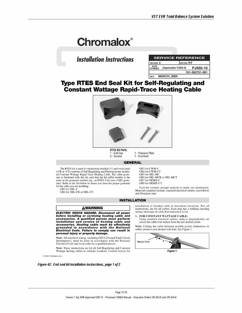
VST EVR Total Balance System Solution
Page 15-79 Version 1.0(j) ARB Approved IOM 15 – Processor OM&S Manual – Executive Orders VR-203-E and VR-204-E
Figure 42: End seal kit installation instructions, page 1 of 2
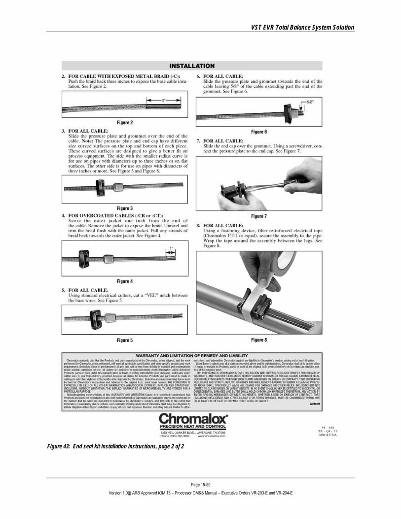
VST EVR Total Balance System Solution
Page 15-80 Version 1.0(j) ARB Approved IOM 15 – Processor OM&S Manual – Executive Orders VR-203-E and VR-204-E
Figure 43: End seal kit installation instructions, page 2 of 2

VST EVR Total Balance System Solution
Page 15-81 Version 1.0(j) ARB Approved IOM 15 – Processor OM&S Manual – Executive Orders VR-203-E and VR-204-E
Figure 44: Prepare the new heat trace cable for installation into the end seal kit
A. Twin 14 AWG copper buss wires
B. Semi-conductive polymer core
C. High temp. fluoropolymer jacket
D. Metallic braid ground
E. High temperature fluoropolymer jacket

VST EVR Total Balance System Solution
Page 15-82 Version 1.0(j) ARB Approved IOM 15 – Processor OM&S Manual – Executive Orders VR-203-E and VR-204-E
Figure 45: Electrical junction box installation instructions, page 1 of 4
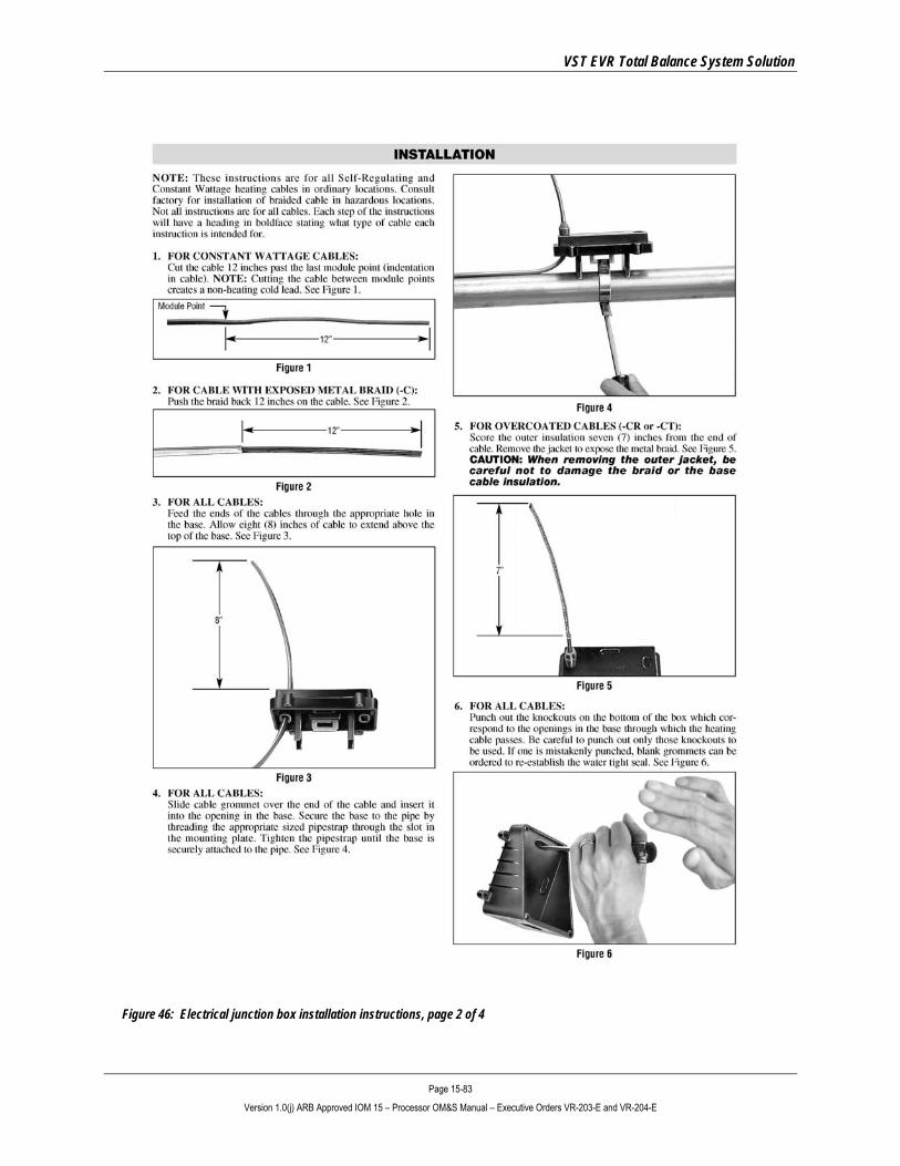
VST EVR Total Balance System Solution
Page 15-83 Version 1.0(j) ARB Approved IOM 15 – Processor OM&S Manual – Executive Orders VR-203-E and VR-204-E
Figure 46: Electrical junction box installation instructions, page 2 of 4
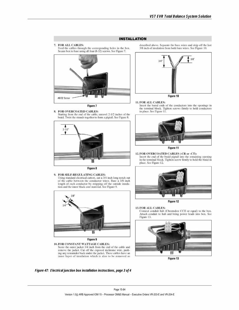
VST EVR Total Balance System Solution
Page 15-84 Version 1.0(j) ARB Approved IOM 15 – Processor OM&S Manual – Executive Orders VR-203-E and VR-204-E
Figure 47: Electrical junction box installation instructions, page 3 of 4
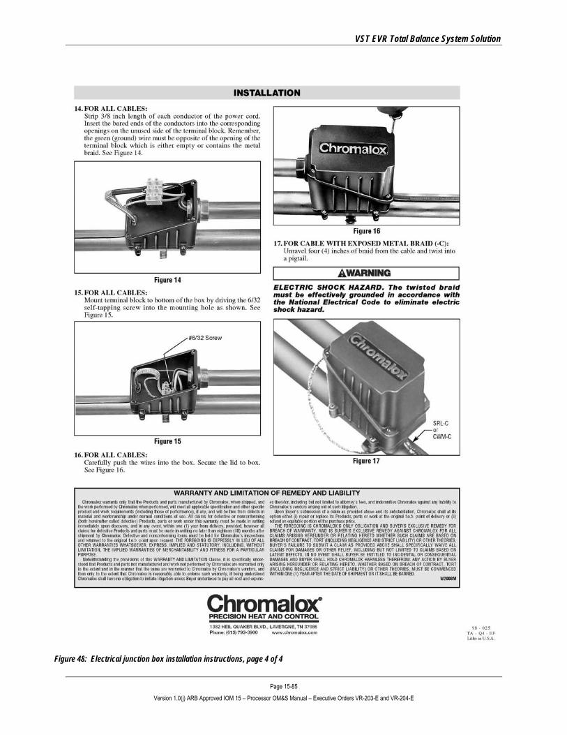
VST EVR Total Balance System Solution
Page 15-85 Version 1.0(j) ARB Approved IOM 15 – Processor OM&S Manual – Executive Orders VR-203-E and VR-204-E
Figure 48: Electrical junction box installation instructions, page 4 of 4

VST EVR Total Balance System Solution
Page 15-86 Version 1.0(j) ARB Approved IOM 15 – Processor OM&S Manual – Executive Orders VR-203-E and VR-204-E
Figure 49: End seal kit location and heat trace cable installation
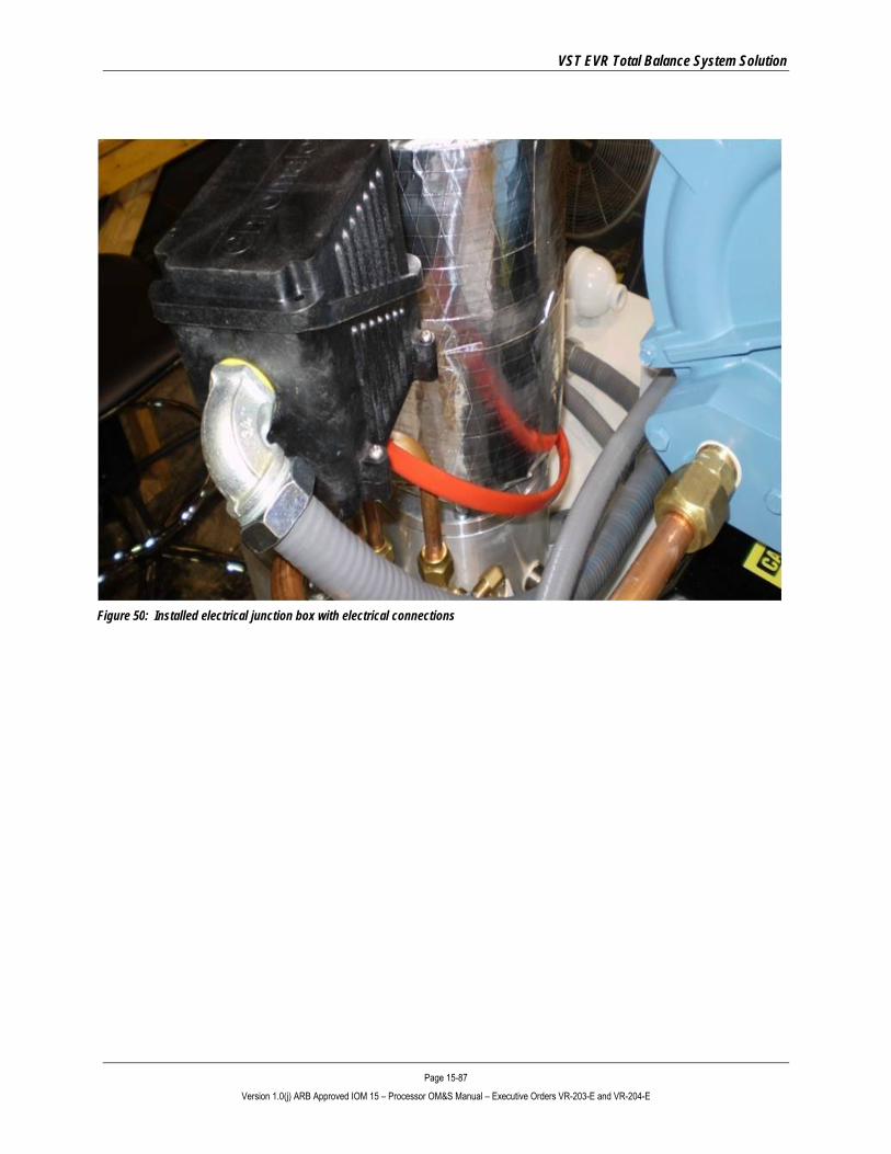
VST EVR Total Balance System Solution
Page 15-87 Version 1.0(j) ARB Approved IOM 15 – Processor OM&S Manual – Executive Orders VR-203-E and VR-204-E
Figure 50: Installed electrical junction box with electrical connections

VST EVR Total Balance System Solution
Page 15-88 Version 1.0(j) ARB Approved IOM 15 – Processor OM&S Manual – Executive Orders VR-203-E and VR-204-E
12 Hydrocarbon Infrared (HC IR) Sensor Module Replacement
12.1 Safety
Use lockout / tagout procedures prior to starting work.
Figure 51: HC IR Sensor Module and Electrical Housing Assembly
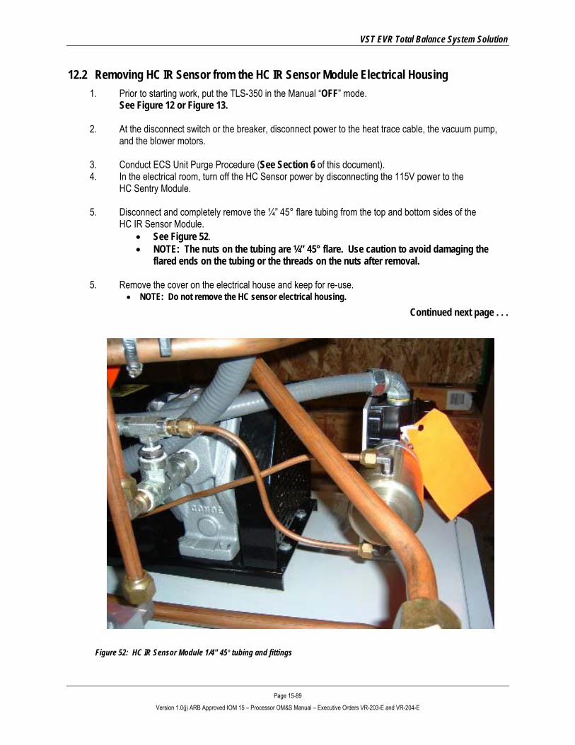
VST EVR Total Balance System Solution
Page 15-89 Version 1.0(j) ARB Approved IOM 15 – Processor OM&S Manual – Executive Orders VR-203-E and VR-204-E
12.2 Removing HC IR Sensor from the HC IR Sensor Module Electrical Housing 1. Prior to starting work, put the TLS-350 in the Manual “OFF” mode.
See Figure 12 or Figure 13.
2. At the disconnect switch or the breaker, disconnect power to the heat trace cable, the vacuum pump, and the blower motors.
3. Conduct ECS Unit Purge Procedure (See Section 6 of this document). 4. In the electrical room, turn off the HC Sensor power by disconnecting the 115V power to the
HC Sentry Module.
5. Disconnect and completely remove the ¼” 45° flare tubing from the top and bottom sides of the HC IR Sensor Module.
• See Figure 52. • NOTE: The nuts on the tubing are ¼” 45° flare. Use caution to avoid damaging the
flared ends on the tubing or the threads on the nuts after removal.
5. Remove the cover on the electrical house and keep for re-use. • NOTE: Do not remove the HC sensor electrical housing.
Continued next page . . .
Figure 52: HC IR Sensor Module 1/4" 45º tubing and fittings

VST EVR Total Balance System Solution
Page 15-90 Version 1.0(j) ARB Approved IOM 15 – Processor OM&S Manual – Executive Orders VR-203-E and VR-204-E
6. Disconnect the following HC IR sensor wires from the electrical housing circuit board: • White: 4-20 mA signal wire
• Black: -(common) RET wire
• Red: +24VDC power wire
• NOTE: The yellow and green wires are not used in this application.
• See Figures 53 and 54.
7. Unscrew and remove the HC IR Sensor Module from the electrical housing.
• Package the used HC IR Sensor Module in the anti-static bag and box that came with the new / recalibrated HC IR Sensor Module unit.
• The used HC IR Sensor Module can be sent back to VST for re-calibration.
Figure 54: HC IR Sensor Electrical Housing Circuit Board Wiring Diagram
Figure 53: HC IR Sensor Electrical Housing Circuit Board
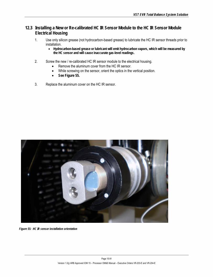
VST EVR Total Balance System Solution
Page 15-91 Version 1.0(j) ARB Approved IOM 15 – Processor OM&S Manual – Executive Orders VR-203-E and VR-204-E
12.3 Installing a New or Re-calibrated HC IR Sensor Module to the HC IR Sensor Module Electrical Housing 1. Use only silicon grease (not hydrocarbon-based grease) to lubricate the HC IR sensor threads prior to
installation. • Hydrocarbon-based grease or lubricant will emit hydrocarbon vapors, which will be measured by
the HC sensor and will cause inaccurate gas-level readings.
2. Screw the new / re-calibrated HC IR sensor module to the electrical housing. • Remove the aluminum cover from the HC IR sensor. • While screwing on the sensor, orient the optics in the vertical position. • See Figure 55.
3. Replace the aluminum cover on the HC IR sensor.
Figure 55: HC IR sensor installation orientation
VST EVR Total Balance System Solution
Page 15-92 Version 1.0(j) ARB Approved IOM 15 – Processor OM&S Manual – Executive Orders VR-203-E and VR-204-E
4. Connect the following HC IR sensor wires to the electrical housing circuit board:
• White: 4-20 mA signal wire • Black: -(common) RET wire • Red: +24VDC power wire • NOTE: the yellow and green wires are not used in this application. • See Figures 53 and 54.
5. Install the cover on the electrical housing.
• Use only silicon grease (not hydrocarbon-based grease) to lubricate the cover threads prior to installation.
• Hydrocarbon-based grease or lubricant will emit hydrocarbon vapors, which will be measured by the HC sensor and will cause inaccurate gas-level readings.
6. Re-install the (2) ¼” 45° flare tubing on the top and bottom sides of the HC IR sensor module.
• NOTE: When tightening the 45° flare nuts, clamp the tube flare between the nut and the nose body of the tube by screwing the nut on finger-tight. Tighten with a wrench an additional ¼-turn for a metal-to-metal seal.
7. Remove the lock(s) and tags from the lockout/tagout.
8. At the breaker and at the disconnect switch, turn ON power to the heat trace, blower, and vacuum pump.
9. In the electrical room, turn ON power to the HC Sentry Module.
10. Perform a Processor Leak Test – see Section 3.8 of this document.
11. After the installation is complete, put the TLS-350 in the AUTOMATIC ON mode.
• See Figure 12 or 13.

VST EVR Total Balance System Solution
Page 15-93 Version 1.0(j) ARB Approved IOM 15 – Processor OM&S Manual – Executive Orders VR-203-E and VR-204-E
13 Forms • The following pages contain forms for:
► Scheduled preventative maintenance list ► Scheduled preventative maintenance checklist

VST EVR Total Balance System Solution
Page 15-94 Version 1.0(j) ARB Approved IOM 15 – Processor OM&S Manual – Executive Orders VR-203-E and VR-204-E
13.1 Preventative Maintenance
Preventative Maintenance ASC #:
Date:
ASC Name:
ASC Certification Level:
ASC Company:
GDF Name: Address: City:
State:
ZIP Code:
GDF Contact Person Name:
GDF Contact Person Title:
GDF Contact Person Phone:
GDF Contact Person E-mail:
Notes
Use the form on the following page to note details of Preventative Maintenance activities.

VST EVR Total Balance System Solution
Page 15-95 Version 1.0(j) ARB Approved IOM 15 – Processor OM&S Manual – Executive Orders VR-203-E and VR-204-E
13.2 Preventative Maintenance Checklist Form
Component
Frequency
Date Inspected
Completed
Required
Action Items
PROCESSOR Yearly
• Inspect drive coupling on vacuum pump. []
• Check the continuity of the heat trace cable. []
RECIRCULATION BLOWER
• Replace every 10 years or every 15,000 hours, whichever comes first.
[]
VACUUM PUMP
• Replace every 10 years or every 15,000 hours, whichever comes first.
[]