operations manual - rk · operations manual. rk2 10 ac protein ... attach the internal riser rinse...
TRANSCRIPT

RRSYSTEMSSAN DIEGO, CA
RK10AC-PFPROTEIN FRACTIONATOR
KK22
Operations Manual

RK2 10 AC Protein Fractionator
I. IntroductionII. Tools, parts and hardwareIII. Unpacking proceduresIV. Assembly proceduresV. Appendix: Components
I. Introduction
Congratulations on your purchase of the RK2 10 AC Protein Fractionator. This sophisticatedfiltration system is recommended for aquaria of up to 1000 gallons, and, when operated andmaintained correctly, will provide many years of service, clean water, and health for aquaticlife systems.
Should any technical issues arise during assembly or operation of this unit,please contact your RK2 Systems Distributor.
II. Tools, Parts and Hardware
The RK2 10 AC is simple to assemble, with only a few tools necessary and very few nuts, boltsand washers to keep track of.
Tools & Supplies Needed:Flat head screwdriverOne 1/4 “ open-end, crescent or socket wrenchBox-cutter or similar bladeOne tube of Silicone Grease
NOTE: Pipe wrenches are not recommended for assembly of the10 AC and typically result in damage to the unit.)
Hardware included:(For top assembly)Twelve 1/4” x 2” boltsTwelve 1/4” x 5/8” standard flat washers
(For pump mount)Two 1/4” x 1.5” boltsFour 1/4” x 5/8” washers
(For Reaction Chamber base)Four 1 1/4” x 1/4” boltsFour washers (SIZE?)
III. Unpacking Procedures
1. Using the box cutter, remove plastic straps and plastic wrap from the RK2 10 AC box andpallet.
HELPFUL HINT: The lid makes a useful tray to keep some of the hardwarecomponents together for assembly.
2. Using the flat head screwdriver, remove the staples from the bottom of the carton.
3. Lift the carton off the bottom of the box.
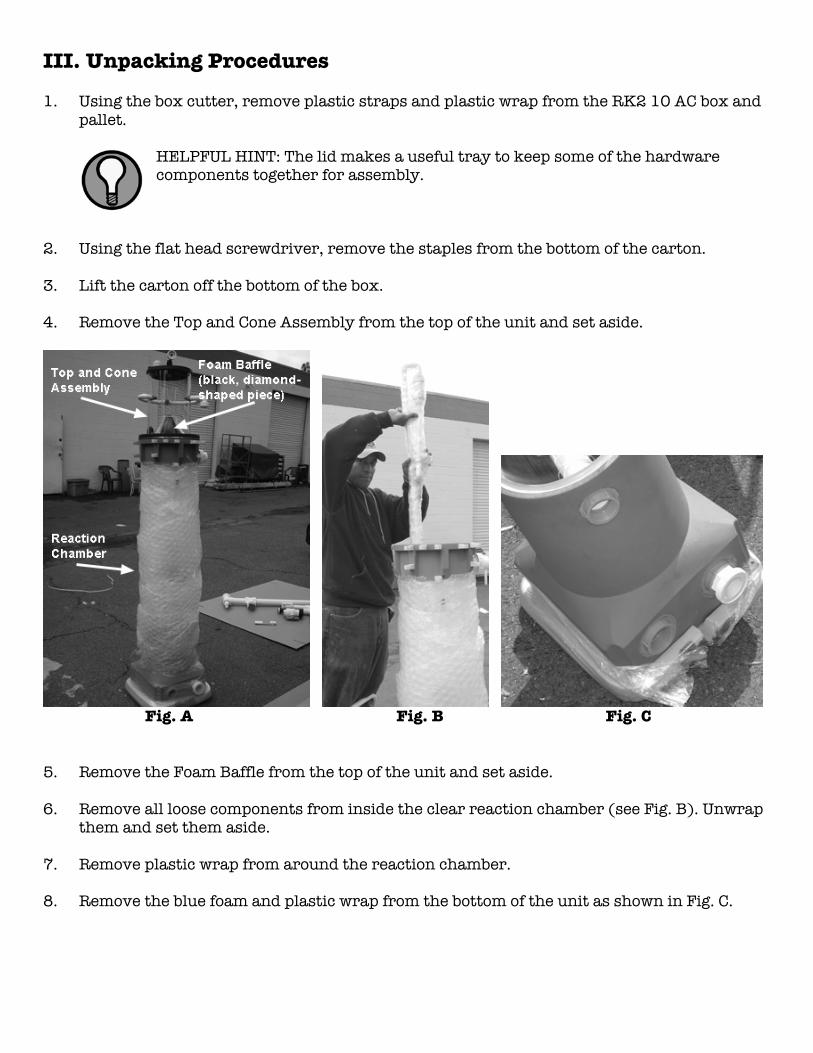
4. Remove the Top and Cone Assembly from the top of the unit and set aside.
Fig. A Fig. B Fig. C
5. Remove the Foam Baffle from the top of the unit and set aside.
6. Remove all loose components from inside the clear reaction chamber (see Fig. B). Unwrapthem and set them aside.
7. Remove plastic wrap from around the reaction chamber.
8. Remove the blue foam and plastic wrap from the bottom of the unit as shown in Fig. C.

IV. Assembly Procedures
Mounting the Pump
1. Using the bolts included (they are shipped threaded into their appropriate holes), securethe grey base of the reaction chamber to the grey rectangular platform. Bolts should besnug, and not excessively tight. See Fig. 1.
2. Attach the Venturi Ball Valve as shown in Fig. 2. Remove any tape found on the threads.
Fig. 1 Fig. 2 Fig. 4
3. Note the two bolts on the opposite side of the platform from the base of the reactionchamber. These bolts are for securing the pump. Remove bolts and washers and set aside.
4. Place the black rubber pump base so that its indentations line up over the holes for thepump. (See Fig. 4.)
5. Position the pump on the base, and hand-tighten the pump valve onto the 2” ball valve, asshown in Fig. 5, until the surfaces are flush. Use Figs. 5B and 5C to observe how a unionlooks when it is flush or not flush. (See WARNING, next page.)
Fig. 5A Fig. 5B Fig 5C
WARNING: Do NOT USE A WRENCH to tighten this union, or a rupture willmost likely result. Do not over-tighten this union!
6. Insert and tighten the bolts set aside in Step 3 to finish securing the pump.
Mounting the External Plumbing
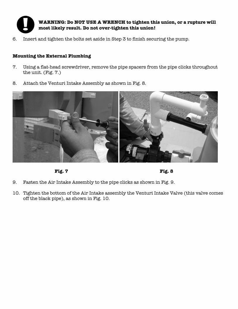
7. Using a flat-head screwdriver, remove the pipe spacers from the pipe clicks throughoutthe unit. (Fig. 7.)
8. Attach the Venturi Intake Assembly as shown in Fig. 8.
Fig. 7 Fig. 8
9. Fasten the Air Intake Assembly to the pipe clicks as shown in Fig. 9.
10. Tighten the bottom of the Air Intake assembly the Venturi Intake Valve (this valve comesoff the black pipe), as shown in Fig. 10.

Fig. 9 Fig. 10
11. Install the Discharge Plumbing as shown in Fig. 11, by affixing to the pipe click, andsnugly tightening the lower union to the outlet from the bottom of the Reaction Chamber.
12. Attach the Discharge Air Vent to the top of the Discharge Plumbing as shown in Fig. 12.
Fig. 11 Fig. 12

13. Install the External Wash Timer Assembly by clipping the timer onto the bracket of theDischarge Plumbing and affixing the solenoid valve to the pipe clicks as shown in Fig 13Aand 13B.
14. Place the Foam Baffle at the top of the Reaction Chamber, lining up its four sides with thenotches as shown in Fig. 14.
Fig. 13A Fig. 13B
Fig. 14

15. Place the Top and Cone Assembly on top of the Reaction Chamber as shown in Fig. 15A,and tighten the 2” x 1/4” bolts in pairs of opposites as shown in Fig. 15B.
Fig. 15A Fig. 15B
16. Apply silicon grease to lubricate and seal the 2” port near the top of the reaction chamber,as shown in Fig. 16.
Fig. 16 Fig. 17
17. Insert the Waste Drain into the port and attach to the pipe clicks as shown in Fig. 17.
NOTE: The PSI of the water running through this part of the 10 AC is extremelyLOW. Because of that, you do not need to tighten the bolts beyond what is snug.
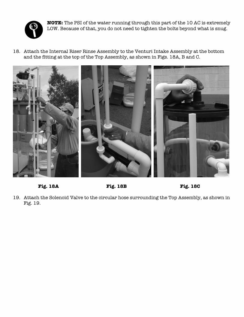
18. Attach the Internal Riser Rinse Assembly to the Venturi Intake Assembly at the bottomand the fitting at the top of the Top Assembly, as shown in Figs. 18A, B and C.
Fig. 18A Fig. 18B Fig. 18C
19. Attach the Solenoid Valve to the circular hose surrounding the Top Assembly, as shown inFig. 19.

Fig. 19 Fig. 20
Congratulations! You have successfully assembled the RK 10 AC! (See Fig. 20.) Now it’s timeto plumb the RK 10 AC to the outside world.
21. Plumb the Waste Drain to the sewage line.
22. Plumb the Intake Valve Assembly to the source of dirty water, such as an aquarium, etc.
23. Plum the 2” Discharge to reservoir.
WARNING: Immediately after the 2” Discharge, you must provide a minimum of12” vertical drop. Do not install horizontal piping until you have provided 12” ofvertical drop.
NOTE: The intake flow is designed to be 10 GPM.
24. After you have completely connected the RK 10 AC, fire it up! Then inspect for any unionsor nuts/bolts that leak, and hand tighten.

Appendix: Components
Included within the Reaction Chamber (main structural component of the RK 10 AC)and accompanying boxes there are some components wrapped in bubble-wrap that youwill need to install. They are shown below for your reference:
Venturi Intake Assembly Venturi Pump Intake Air Gauge Assembly Ball Valve
External Wash Timer Assembly Discharge Plumbing Discharge Air Vent

Appendix (continued)
Foam Baffle Internal Rinse Riser Assembly
Waste Drain Hardware for Top/Cone Assembly


Bulletin F-43
DWYER INSTRUMENTS, INC. Phone: 219/879-8000 www.dwyer-inst.comP.O. BOX 373 • MICHIGAN CITY, IN 46361, U.S.A. Fax: 219/872-9057 e-mail: [email protected]
Specifications - Installation and Operating Instructions
Series RM Rate-Master®
Flowmeters
F
AB C
JBACK WIDTH
K
D
E
G
H
IFULL OPEN L
Dwyer Series RM Rate-Master®
Flowmeters are furnished in threemodels (see Fig. 2), each available in a broad array of flow ranges withdirect reading scales for air, gas or water. Installation, operation and main-tenance are very simple. Only a few common-sense precautions must beobserved to assure long, trouble-free service.
CAUTION: Dwyer Rate-Master® Flowmeters are designed to provide sat-isfactory long-term service when used with air, water or other compatiblemedia. Refer to factory for information on questionable gases or liquids.Avoid solutions of acids, bases or salts having a pH below 5.0 or above8.5. Caustic solutions, antifreeze (ethylene glycol) and aromatic solventsshould definitely not be used.
CalibrationEach Rate-Master® Flowmeter is calibrated at the factory. If at any timeduring the meter’s life, you wish to re-check its calibration, do so only withdevices of certified accuracy. DO NOT attempt to check a Rate-Master®
Flowmeter with a similar flowmeter, as seemingly unimportant variations inpiping and back pressure may cause noticeable differences in the indicat-ed reading. If in doubt, return your Dwyer Rate-Master® Flowmeter to thefactory. Its calibration will be checked for you at no charge. Before pro-ceeding with installation, check to be sure you have the Rate-Mastermodel and flow range you require.
LOCATION: Temperature, Pressure, Atmosphere and Vibration:Dwyer Rate-Master® Flowmeters are exceptionally tough and strong. Theyare designed for use at pressures up to 100 psi (6.89 bar) and tempera-tures up to 130°F (54°C).
DO NOT EXCEED THESE LIMITS! The installation should not be exposedto strong chlorine atmospheres or solvents such as benzene, acetone,carbon tetrachloride, etc. The mounting panel should be free of excessivevibration, as it may prevent the unit from operating properly.
A
B
C
D
E
F
G
H
I (OPEN)
J
K
L
4 -9/16 (11.59)
3 (7.62)1/8 NPT CONN.
1-5/8 (3.17)10 - 32 Thds.
3/8 (.95)
1-1/16 (2.60)
1-3/16 (2.73)
3/4 (1.91)
1 (2.54)
1-3/8 (3.49)
3/4 (1.91)
4-13/16 (12.22)
1 (2.54)
8-1/2 (21.59)
6-7/16 (16.35)1/4 NPT CONN.
3-15/16 (8.56)1/4 - 20 Thds.
5/8 (1.59)
1-7/8 (3.42)
1-3/4 (3.29)
1 (2.54)
1-7/16 (2.98)
1-13/16 (4.60)
1-1/4 (3.18)
8-3/4 (22.23)
1-1/2 (3.81)
Dimensions in Inches (Centimeters)
15 -1/8 (38.42)
12 -1/4 (31.12)1/2 NPT CONN.
8-3/4 (10.72)10 - 32 Thds.
1 (2.54)
2-3/4 (5.83)
2-1/4 (5.33)
1-7/16 (2.98)
1-31/32 (3.51)
2-1/2 (6.35)
2 (5.08)
15-3/8 (39.05)
2-1/4 (5.72)
Inlet Piping Run: It is good practice to approach the flowmeter inlet withas few elbows and restrictions as possible. In every case, the inlet pipingshould be at least as large as the connection to the flowmeter; i.e.,1/8″Iron Pipe Size for RMA models 1/4″ IPS for RMB models,1/2″ IPS for RMCmodels. Length of inlet piping makes little difference for normal pressure-fed flowmeters.
For flowmeters on vacuum air service, the inlet piping should be as shortand open as possible. This will allow operation near atmospheric pressureand thereby insure the accuracy of the device. (Note: for vacuum air ser-vice, the flow control valve, if any, should be on the discharge side of theflowmeter. Either the TMV unit or a separate in-line valve may be applied.).
Discharge Piping: As on the inlet, discharge piping should be at least aslarge as the flowmeter connection. Also, for pressure-fed flowmeters onair or gas service, the discharge piping should be as short and open aspossible. This will allow operation of the flow tube at near atmosphericpressure and insure the accuracy of the device. This is of less importanceon water or liquid flowmeters, as the flowing medium is generally incom-pressible and moderate back pressure will not affect the accuracy of theinstrument as calibrated.
POSITIONING AND MOUNTINGAll Rate-Master® Flowmeters must be mounted in a vertical position withinlet connection at the bottom rear and outlet at the top rear.
Bezel or Through-Panel Mounting: Make panel cutout using appropri-ate dimensions from Fig. 2. Flowmeter must fit into panel freely withoutforcing or squeezing. Insert the flowmeter from the front of the panel andinstall the mounting clamps from the rear. Insert and tighten the clampbolts in the locations shown in Fig. 3. Do not exceed 5 in./lbs. Make con-nections to inlet and outlet ports using small amount of RTV sealant orTeflon® thread tape to avoid leakage. Avoid excess torque, which maydamage the flowmeter body.
PANEL CUTOUT FOR FLUSH MOUNTING
4-5/8 (11.75)
7/8 (2.22)
7/16 (1.11)
1/4 (0.64)
8-9/16 (21.75)
1-5/16 (3.33)
5/8 (1.59)
9/32 (0.71)
15 -3/16 (38.58)
2-1/16 (5.24)
15/16 (2.38)
13/32 (1.03)
HIGHWIDE
PIPEBOLT
Model RMA Model RMB Model RMC
Fig. 1 Fig. 2PANEL HOLE SIZES FOR SURFACE MOUNTING
Bulletin F-43 9/14/05 9:01 AM Page 1

Fig. 3 Fig. 4
Fig. 5Fig. 6
Fig. 7Fig. 5B Fig. 6B
Surface Mounting: Drill appropriate holes in panel, using the dimensionsshown in Fig. 2. Hold the flowmeter in position in front of the panel andinstall the clamp bolts from the rear. (The mounting clamps may be usedas washers, if desired, by installing them backwards or straightening themout.) Pipe up inlet and discharge following the directions in the previoussections.
Surface Mounting on Piping Only: An alternate method of surfacemounting, omitting the clamp bolts and supporting the flowmeter solely onthe connecting piping, is possible. For this method, extra-long or straightpipe threads should be used so that nuts may be run onto the pipe andlater tightened against the back of the panel to retain the unit in properposition. Use appropriate hole layout in formation from Fig. 2, but omit thesmall holes.
Surface Mounting on Piping Only Without Panel: For a temporary orlaboratory type installation, the panel may be omitted altogether and theflowmeter installed directly in rigid piping. Its light weight permits this with-out difficulty.
OPERATIONTo start system, open valve slowly to avoid possible damage. Controlvalves on BV and SSV models are turned clockwise to reduce flow,counter-clockwise to increase flow. A nylon insert is provided in the thread-ed section of the valve stem to give a firm touch to valve and to preventchange of setting due to vibration.
The performance of low range units used in air or gas applications may beaffected by static electricity. Excessive static charge may cause the ballfloat to behave erratically or provide a false reading. To ensure the properfunction of the unit, the application should be designed to minimize or dis-pel static electricity.
The standard technique for reading a Variable Area Flowmeter is to locatethe highest point of greatest diameter on the float, and then align that withthe theoretical center of the scale graduation. In the event that the float isnot aligned with a grad, an extrapolation of the float location must be madeby the operator as to its location between the two closest grads. The fol-lowing are some sample floats shown with reference to the proper locationto read the float.
Variable Area Flowmeters used for gases are typically labeled with the pre-fix “S” or “N”, which represents “Standard” for English units or “Normal” formetric units. Use of this prefix designates that the flowmeter is calibratedto operate at a specific set of conditions, and deviation from those stan-dard conditions will require correction for the calibration to be valid. In prac-tice, the reading taken from the flowmeter scale must be corrected back tostandard conditions to be used with the scale units. The correct location tomeasure the actual pressure and temperature is at the exit of the flowme-ter, except when using the Top Mounted Valve under vacuum applications,where they should be measured at the flowmeter inlet. The equation to cor-rect for nonstandard operating conditions is as follows:
Q2 = Q1 x P1 x T2
P2 x T1
Where: Q1 = Actual or Observed Flowmeter ReadingQ2 = Standard Flow Corrected for Pressure and Temperature
P1 = Actual Pressure (14.7 psia + Gage Pressure)P2 = Standard Pressure (14.7 psia, which is 0 psig)T1 = Actual Temperature (460 R + Temp °F)T2 = Standard Temperature (530 R, which is 70°F)
Example: A flowmeter with a scale of 10-100 SCFH Air. The float is sittingat the 60 grad on the flowmeter scale. Actual Pressure is measured at theexit of the meter as 5 psig. Actual Temperature is measured at the exit ofthe meter as 85°F.
Q2 = 60.0 x (14.7 + 5) x 53014.7 x (460 + 85)
Q2 = 68.5 SCFH Air
CAUTION: Do not completely unscrew valve stem unless the flowmeter isunpressurized and drained of any liquid. Removal while in service will allowgas or liquid to flow out the front of the valve body and could result in seri-ous personal injury. For applications involving high pressure and/or toxicgases or fluids, special non-removable valves are available on specialorder. Please contact factory for details.
MAINTENANCEThe only maintenance normally required is occasional cleaning to assurereliable operation and good float visibility.
Disassembly: The flowmeter can be disassembled for cleaning simply as follows:
1. Remove valve knob from RMB or RMC -BV or -SSV units by pulling theknob forward. It is retained by spring pressure on the stem half-shaft sothat a gentle pull will remove it. On RMA-BV or -SSV models, turn the valveknob counter-clockwise until the threads are disengaged. Then withdrawthe stem from the valve by gently pulling on the knob.
2. Remove the four mounting bracket screws located in the sides of theflowmeter. See Fig. 3. Pull the flowmeter body gently forward away fromthe back plate to avoid undue strain on the body. Leave the piping con-nections intact. There is no need to disturb them. See Fig. 4.
3. Threaded body style flowmeters - Remove the slip cap with a push ona screwdriver as shown in Fig. 5. Remove the plug ball stop as shown inFig. 6 using allen wrench sizes as follows: Model RMA - 1/4″, Model RMB- 1/2″ and Model RMC - 3/4″ Threadless body style flowmeters - Releasethe plastic retaining clip with a screw driver (Figure 5B), it will unclip fromthe valve body (TMV Option) or the plug ball stop, slide the clip back untilthe valve body or ball stop can be removed. The clip will remain in the bodyfor convenience. Using a screwdriver gently lift up on the plug in the grooveas shown in Figure 6B until the o-ring seal is released and remove the plug.For the TMV option gently pull up on the valve knob to release the valvebody seals and remove the valve.
4. Take out the ball or float by inverting the body and allowing the floatto fall into your hand, as shown in Fig. 7. (Note: It is best to cover the dis-charge port to avoid losing the float through that opening.)
Cleaning: The flow tube and flowmeter body can best be cleaned with alittle pure soap and water. Use of a bottle brush or other soft brush will aidthe cleaning. Avoid benzene, acetone, carbon tetrachloride, alkaline deter-gents, caustic soda, liquid soaps (which may contain chlorinated solvents),etc. Also, avoid prolonged immersion, which may harm or loosen thescale.
Reassembly: Simply reverse steps 1 through 4 and place the flowmeterback in service. A little stopcock grease or petroleum jelly on the “O” ringswill help maintain a good seal as well as facilitate assembly. No other spe-cial care is required.
MOUNTING BRACKETSCREW 4 REQUIRED
DWYER INSTRUMENTS, INC. Phone: 219/879-8000 www.dwyer-inst.comP.O. BOX 373 • MICHIGAN CITY, IN 46361, U.S.A. Fax: 219/872-9057 e-mail: [email protected]
©Copyright 2005 Dwyer Instruments, Inc. Printed in U.S.A. 9/05 FR# 56-440197-00 Rev. 16Teflon® is a registered Trademark of E.I. DuPont Company
Bulletin F-43 9/14/05 9:01 AM Page 2

Proper Protein Fractionator Adjustment A protein skimmer (actually a protein fractionator) is not a 'plug and play' piece of equipment. It requires close attention to achieve proper adjustment. This proper adjustment is critical to achieving the maximum performance from the unit. The fractionator is adjusted by creating back pressure at the discharge by throttling the discharge valve. The gas intake and water inlet need to be set to their recommended flow rates. Throttling back the discharge valve increases the back pressure and raises the foam level in the upper chamber. This is basically a hydraulic balancing procedure. (Do not throttle water or air flow to and from the venturis to control foam height. Venturi water valves should run in the open position. Venturi air intakes should be adjusted to a 1” to 2” vacuum.) The fractionator needs to be adjusted to a level that consistently produces an effluent the color of weak tea or ginger ale. Lowering the foam level to the point where it only produces dry foam and a dark effluent inhibits the removal of waste products. A new installation that has not had any fractionation for more than a few days will require 2 to 7 days for the system to achieve a level of stable organic removal. Protein fractionators remove compounds from the water by injecting fine bubbles into the water. Organic compounds 'stick' to the surface tension of the water which includes the surface of the bubbles. As the organic laden foam rises into the upper chamber it overflows into the collection area. The discharge valve adjustment combined with the Bio-load (and certain additives) will affect the foam level. If the foam level is set too low the protein fractionator will only remove a small amount of waste even from very dirty water. Waste levels which are below this threshold remain in the water since the protein fractionator is not adjusted to remove them. The result of this level of adjustment is a very dark, concentrated waste extract from the protein fractionator. When this is occurring the aquarist has no way of determining how efficient the protein fractionator is working other than by observing the color of the water in the aquarium. Adjusting the level too high creates a situation where the fractionator is removing a large amount of water that has very little dissolved organics. To properly adjust a protein fractionator takes at least several days of observation and adjustments. You should allow a minimum of a half an hour between adjustments to allow the hydraulics to settle into balance. There are a couple things to remember to achieve proper adjustment. The first is the protein fractionator only removes waste to the threshold you have set. As it approaches this threshold it removes less and less resulting in a concentrated extract. The other is that the extract should be roughly the color of ginger ale or weak tea. If it is darker, the threshold is set too low. To adjust the fractionator properly the following must be done: 1. Make sure the venturi and inlet flows are set to the recommended rates. 2. Adjust the protein fractionator by throttling the discharge valve so that the extract is about the color of ginger ale or weak tea. Ideally you will produce a sudsy foam that is between the consistency of water and shaving cream. 3. Let it run, even though it may run wet for a while. As it approaches the new threshold level for waste extraction it will begin to slow down and the extract will become darker and more concentrated. When this happens repeat step 1 and step 2. 3. When the point is reached that the protein fractionator does not slow down after a few days then it can be assumed that the protein skimmer is properly adjusted. In the case of very dirty water this process may take quite a number of adjustments and may take longer to slow down the first time. Keep the protein fractionator adjusted so that the extract does not become dark.
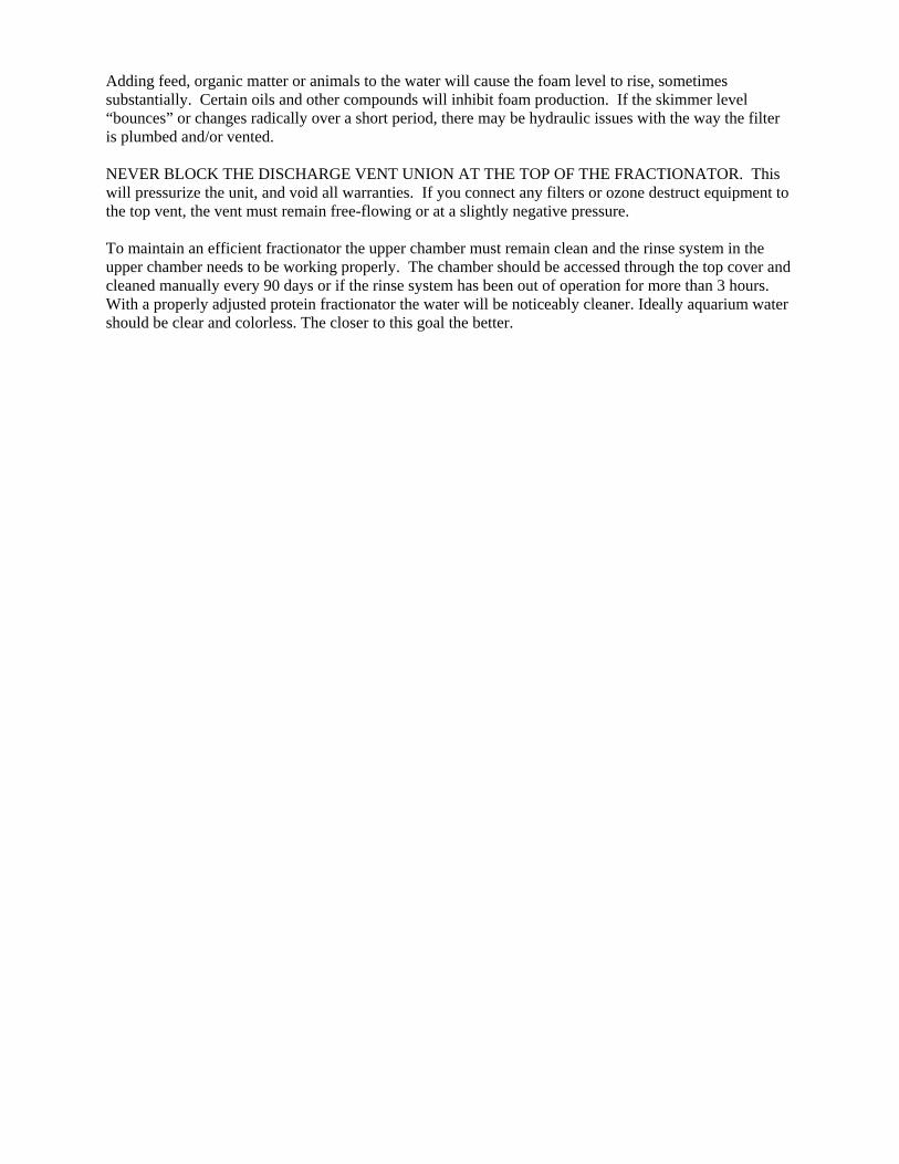
Adding feed, organic matter or animals to the water will cause the foam level to rise, sometimes substantially. Certain oils and other compounds will inhibit foam production. If the skimmer level “bounces” or changes radically over a short period, there may be hydraulic issues with the way the filter is plumbed and/or vented. NEVER BLOCK THE DISCHARGE VENT UNION AT THE TOP OF THE FRACTIONATOR. This will pressurize the unit, and void all warranties. If you connect any filters or ozone destruct equipment to the top vent, the vent must remain free-flowing or at a slightly negative pressure. To maintain an efficient fractionator the upper chamber must remain clean and the rinse system in the upper chamber needs to be working properly. The chamber should be accessed through the top cover and cleaned manually every 90 days or if the rinse system has been out of operation for more than 3 hours. With a properly adjusted protein fractionator the water will be noticeably cleaner. Ideally aquarium water should be clear and colorless. The closer to this goal the better.
PRODUCT WARRANTY TERMS
RK2 Systems, Inc. (The Seller) warrants to the original purchaser, that products of its ownmanufacture will be free from defects in materials or workmanship, under normal use andservice, for a period of one year from the date of purchase (with the exception of a vessel, whichis warranted for three years). The Seller’s obligations under this Warranty are limited toreplacing or repairing or giving credit for, at its option, any of its said products which shall,within one year after purchase, be returned to the Seller’s place of origin, transportation chargesprepaid, and which are, after products examined, disclosed to the Seller’s satisfaction to be thusdefective. This Warranty does not apply to defects caused by shipping damages, or to anyproducts manufactured by Seller which have been subject to improper installation, misuse,neglect, accident, ordinary wear and tear, or Buyer’s attempts to use any products beyond itsmechanical, thermal, or electrical capacity. Notice of a defective product must be given to Sellerin writing within 48 hours of discovery and be free, without limitation of labor charges, lostprofits, expenses of repair or other costs incidental to replacement. All transportation costsincurred in shipping product to or from Seller’s plant shall be at the Buyer’s expense. Theaforementioned provisions do not extend the original Warranty period of any product which haseither been partially repaired or replaced by the Seller.
FOR FURTHER TECHNICAL ASSISTANCE
Contact your RK2 distributor