optical network control
TRANSCRIPT

Optical Network Control
Jorge M. Finochietto
Cordoba – 2014
LCD EFN UNCLaboratorio de Comunicaciones DigitalesFacultad de Ciencias Exactas, Físicas y NaturalesUniversidad Nacional de Córdoba, Argentina

Optical LayerOverview
Control 2 / 59

Outline
1 Network Management
2 Network Protocols
Control 3 / 59

Outline
1 Network ManagementConfiguration ManagementPerformance ManagementFault Management
2 Network Protocols
Control → Network Management 4 / 59
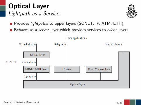
Optical LayerLightpath as a Service
Provides lightpaths to upper layers (SONET, IP, ATM, ETH)
Behaves as a server layer which provides services to client layers
Control → Network Management 5 / 59
Optical LayerRequirements
Lightpaths need tobe setup and taken down as required by the client layerprovide the amount of bandwidth required by the client layerimplement adaptation functions on the client layer to make itcompatible with optical layerguarantee a level of preformance (e.g., BER ≤ 10−12)offer some level of protectionmeet jitter requirements to offer transparency to the client layersupport fault management to address failures and reportroot-cause alarms
A management and control interface between the optical layerand the client layer is required
allows to setup or tear down lightpaths with configurationparametersprovides performance and fault management information to theclient layer
Control → Network Management 6 / 59
Optical LayerManagement and Control
Today lightpaths are set up fairly infrequently and remainednailed down for longs periods of time
In the future, lightpaths could be provisioned dynamically
To this end, there is no need of a signaling interface between theoptical layer and the client oneA network management system (NMS) is used to communicatewith the optical layer network elements (NE)
NEs (e.g., OLT/TLE, ROADM, OXC) are managed by elementmanagement system (EMS)EMS connect to the managed NEs using a data communicationnetwork (DCN)Besides, NEs can communicate each other through a fastsignaling channel (FSC) to exchange real-time control informationEMSs communicate with a NMS through a management network
Besides EMS, a local management system is usually provided toenable craftpeople to manage individual NEs
Control → Network Management 7 / 59

Optical LayerManagement System
Control → Network Management 8 / 59
Optical LayerData Communication Network (DCN)
EMS communicates with NEs through the DCN
DCN can be realized in several ways
Out-of-band separate network outside the optical layer (e.g.,existing TCP/IP network)In-band same network as the optical layer
In-band implies associating a control overhead to
a line (multiple wavelengths) → optical domaina path (one lightpath) → electronic domain
Control → Network Management 9 / 59

Optical LayerOptical Supervisory Channel (OSC)
Available for optical equipment that process multiple wavelengthsMakes use of a separate (dedicated) wavelength from where dataare being transportedOptical amplifiers (i.e., EDFAs) and ROADMs can be managedthis way
For WDM systems in the C-band, the popular choices for theOSC wavelength include 1310nm, 1480nm, 1510nm, or 1620nm.ITU-T has adopted the 1510nm as the preferred choice
Control → Network Management 10 / 59

Optical LayerRate-Preserving Overhead
Available for optical equipment that processes lightpathsUses the same wavelengths where data are being transportedOLT/LTE and OXC with regeneration can be managed this wayOverhead is already required by protocols for other purposeswhich include forward error correction (FEC) overheadIn this context, overhead can be processed at each regenerationstage (endpoints of a lightpath)
Control → Network Management 11 / 59
Optical LayerNetwork Management Functions
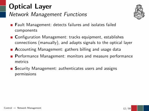
Fault Management: detects failures and isolates failedcomponents
Configuration Management: tracks equipment, establishesconnections (manually), and adapts signals to the optical layer
Accounting Management: gathers billing and usage data
Performance Management: monitors and measure performancemetrics
Security Management: authenticates users and assignspermissions
Control → Network Management 12 / 59
Outline
1 Network ManagementConfiguration ManagementPerformance ManagementFault Management
2 Network Protocols
Control → Network Management → Configuration Management 13 / 59
Configuration ManagementOverview
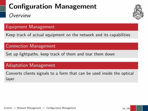
Equipment Management
Keep track of actual equipment on the network and its capabilities
Connection Management
Set up lightpaths. keep track of them and tear them down
Adaptation Management
Converts clients signals to a form that can be used inside the opticallayer
Control → Network Management → Configuration Management 14 / 59
Configuration ManagementConnection Management
Lightpaths pass through multiple nodes
Each lightpath has an unique end-to-end identifier: section trace
Additional identifiers can be used to identify concatenatedlighpaths through 3R regeneration
tandem trace user-defined set of consecutive lighpathspath trace end-to-end connection where client signal travels
These identifiers enables the NMS to identify, verify and managelightpaths
Control → Network Management → Configuration Management 15 / 59
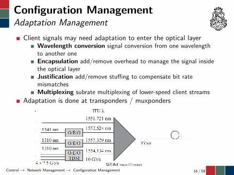
Configuration ManagementAdaptation Management
Client signals may need adaptation to enter the optical layerWavelength conversion signal conversion from one wavelengthto another oneEncapsulation add/remove overhead to manage the signal insidethe optical layerJustification add/remove stuffing to compensate bit ratemismatchesMultiplexing subrate multiplexing of lower-speed client streams
Adaptation is done at transponders / muxponders
Control → Network Management → Configuration Management 16 / 59
Outline
1 Network ManagementConfiguration ManagementPerformance ManagementFault Management
2 Network Protocols
Control → Network Management → Performance Management 17 / 59
Performance vs. Fault ManagementOverview
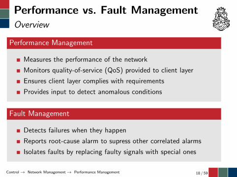
Performance Management
Measures the performance of the network
Monitors quality-of-service (QoS) provided to client layer
Ensures client layer complies with requirements
Provides input to detect anomalous conditions
Fault Management
Detects failures when they happen
Reports root-cause alarm to supress other correlated alarms
Isolates faults by replacing faulty signals with special ones
Control → Network Management → Performance Management 18 / 59

Performance ManagementBER Measurement
Besides signal measurements (power level, chromatic dispersion,etc) bit error rate (BER) is the key performance attributeassociated to a lightpath
Difficult to measure BER accurately on the optical domain (i.e.,based on the SNR)
BER can be computed when signal is available in the electricaldomain
Lightpaths use framing protocols which include overhead byteswhich can be used for in-service BER estimation
Errored Blocks: verifies whether a data block contains errors ornot by means of parity checksCorrected Errors: counts the corrected errors by the ForwardError Correction (FEC) code
Control → Network Management → Performance Management 19 / 59
Performance ManagementBit-Error-Ratio (BER) Measurement
Besides signal measurements (power level, chromatic dispersion,etc) bit error rate (BER) is the key performance attributeassociated to a lightpath
Difficult to measure BER accurately on the optical domain (i.e.,based on the SNR)
BER can be computed when signal is available in the electricaldomain
Lightpaths use framing protocols which include overhead byteswhich can be used for in-service BER estimation
Corrected Errors: counts the corrected errors by the ForwardError Correction (FEC) codeErrored Blocks: verifies whether a data block contains errors ornot by means of parity checks
Control → Network Management → Performance Management 20 / 59

Performance ManagementErrored Block Measurements
Measurements are based on one-second intervals but typicallyregistered in
15-minute counters24-hour counters
A Severely Errored Second (SES) is thus a one-second periodthat contains at least
15 % of errored blocks, orone or more defects such as TIM, PLM, AIS, OCI (more later)
Otherwise, block errors are considered as Background BlockErrors (BBE)
Both SES and BBE can be expressed as the ratio (SESR andBBER) in a time interval (15-minute, 24-hour)
Control → Network Management → Performance Management 21 / 59
Outline
1 Network ManagementConfiguration ManagementPerformance ManagementFault Management
2 Network Protocols
Control → Network Management → Fault Management 22 / 59

Fault ManagementAlignment + Connectivity + Payload
Alignment
Lightpaths transport both data and overhead in a structure knownas frameAn alignment signal is inserted to delineates these frame andextract overhead bytes from the signal
Connectivity
Lighpaths are identified by traces at different levelsIt is possibe then to detect incorrect connections (i.e., tracemismatch)
Payload
Lighpaths carry client signals on their payloadIt is possibe then to detect incorrect payloads (i.e., payloadmismatch)
Control → Network Management → Fault Management 23 / 59
Fault ManagementAlarm Management
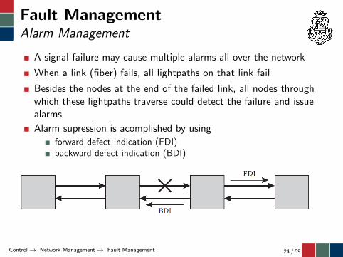
A signal failure may cause multiple alarms all over the network
When a link (fiber) fails, all lightpaths on that link fail
Besides the nodes at the end of the failed link, all nodes throughwhich these lightpaths traverse could detect the failure and issuealarms
Alarm supression is acomplished by using
forward defect indication (FDI)backward defect indication (BDI)
Control → Network Management → Fault Management 24 / 59

Fault ManagementAlarm Supression
When a link fails, the node downstream of the failed link detectsit and generates a defect condition.
A defect condition could be generated because of a high bit errorrate on the incoming signal or an outright loss of light on theincoming signal.
If the defect persists for a certain time period (typically a fewseconds), the node generates an alarm and inserts an FDI signaldownstream to the next node
The FDI is also referred to as the alarm indication signal (AIS)
A node detecting a defect also sends a BDI signal upstream tothe previous node, to notify that node of the failure
If this previous node did not send out an FDI, it then knows thatthe link to the next node downstream has failed.
Control → Network Management → Fault Management 25 / 59

Outline
1 Network Management
2 Network ProtocolsAlignment OverheadFEC OverheadOTU OverheadODU OverheadOPU Overhead
Control → Network Protocols 26 / 59

Optical Transport NetworkOverview
A set of NEs connected by optical fiber links, able to providefunctionality of transport, multiplexing, switching, management,supervision and survivability of optical channels carrying clientsignals
Standarized mainly in ITU-T G.709 + G.798
OTN was designed to provide support for WDM unlike itspredecessor SONET/SDH as well as
to carry much more FEC overheadto provide monitoring of user-defined segments (tandemconnections)to support protocol transparency (CBR service)for asynchronous timing (i.e., frames can be generated usingfree-running oscillators)
Control → Network Protocols 27 / 59
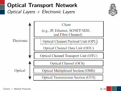
Optical Transport NetworkOptical Layers + Electronic Layers
Control → Network Protocols 28 / 59

Optical Transport NetworkOptical Transmission Section (OTS)
Manages fiber segments between optical components such asbetween optical amplifiers, or optical amplifiers and WDM muxes.
Made up of i) a payload signal (OTS-P), consisting of allwavelengths with data traffic, and ii) an overhead signal(OTS-O) conveying optical supervisory channel (OSC)
Control → Network Protocols 29 / 59

Optical Transport NetworkOTS Continuity Supervision
Loss of Signal Payload (LOS-P) indicates that the incomingpayload signal is absent or that the incoming power level hasdropped below some critical threshold
Loss of Signal Overhead (LOS-O) indicates that the incomingoverhead signal is absent or that the incoming power level hasdropped below some critical threshold
These defects indicate either
a transmitter / receiver failurea path break (e.g., fiber cut, amplifier shutdown)
Control → Network Protocols 30 / 59

Optical Transport NetworkOptical Multiplex Section (OMS)
Each link between OLTs or (R)OADMs represents an OMS
Consists of several OTS segements carrying multiple wavelengths
Has access to the optical supervisory channel (OSC)
Control → Network Protocols 31 / 59

Optical Transport NetworkOptical Channel (Och)
Takes care of end-to-end routing of the lightpaths
A lightpath traverses many fiber links, wherein it is multiplexedwith many other wavelengths carrying other lightpaths
Manages optical connections between 3R regeneration (i.e.,transponders)
Control → Network Protocols 32 / 59

Optical Transport NetworkOch Transport Unit (OTU)
Manages lightpaths provided by the optical layer (OCh) in theelectronic domainDelineates frames, provides identification of the lightpath,monitors its BER performance, carries alarm indicators, andprovides a communication channel between the end pointsAdds the FEC to frames and scrambles them before transmission
Control → Network Protocols 33 / 59

Optical Transport NetworkFrame Structure
Control → Network Protocols 34 / 59
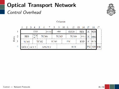
Optical Transport NetworkControl Overhead
Control → Network Protocols 35 / 59
Outline
1 Network Management
2 Network ProtocolsAlignment OverheadFEC OverheadOTU OverheadODU OverheadOPU Overhead
Control → Network Protocols → Alignment Overhead 36 / 59

Alignment OverheadOverhead Fields
Frame Alignment Signal (FAS) A fixed patter consisting of 6bytes are used to delineate each frame
Multiframe Alignment Signal (MFAS) Some of the overheadfields carry information that is dispersed over multiple frames,referred to as multiframes. The MFAS byte is incremented everyframe providing 256 values indicating the number of the framewithin a multiframe.
Control → Network Protocols → Alignment Overhead 37 / 59

Alignment OverheadLoss Conditions (Defects)
Loss of Frame (LOF) indicates that it has not been possible todetect framing for a period of time (3 ms)
Loss of Multiframe (LOM) indicates that it has not beenpossible to detect multiframing for a period of time (3 ms)
Alignment memory: even if in out-of-(multi)frame condition“last” alignment is mantained; thus, the system could enter andrecover from these loss states without changing the actualalignment assumption.
Control → Network Protocols → Alignment Overhead 38 / 59

Outline
1 Network Management
2 Network ProtocolsAlignment OverheadFEC OverheadOTU OverheadODU OverheadOPU Overhead
Control → Network Protocols → FEC Overhead 39 / 59
FEC OverheadCoding Gain
An forward error-correcting code is a technique for reducing thebit error rate on a communicaton channel
It involves transmitting additional bits, called redundancy, alongwith the data bitsThese redundant bits are used by the receiver to correct errors inthe data bits
Increasing tx power may not decrease BER due to non-lineareffects, FEC techniques are typically used for this purposeFEC codes can be characterized by the
overhead, which represents the rate expansion to appendredundancycoding gain, which is the difference (dB) in the OSNR of thecoded and uncoded systems
Since the overhead introduces an OSNR penalty, the coding gainis typicaly defined as the Net Equivalent Coding Gain (NECG)which is the FEC coding gain minus the overhead penalty
Control → Network Protocols → FEC Overhead 40 / 59
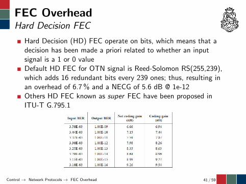
FEC OverheadHard Decision FEC
Hard Decision (HD) FEC operate on bits, which means that adecision has been made a priori related to whether an inputsignal is a 1 or 0 valueDefault HD FEC for OTN signal is Reed-Solomon RS(255,239),which adds 16 redundant bits every 239 ones; thus, resulting inan overhead of 6.7 % and a NECG of 5.6 dB @ 1e-12Others HD FEC known as super FEC have been proposed inITU-T G.795.1
Control → Network Protocols → FEC Overhead 41 / 59
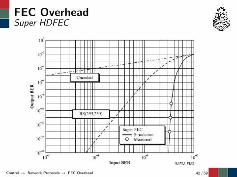
FEC OverheadSuper HDFEC
Control → Network Protocols → FEC Overhead 42 / 59

FEC OverheadSoft Decision FEC
Soft Decision (HD) FEC operate on probabilities, which meansthat a decision has not been made a priori related to whether aninput signal is a 1 or 0 value but its probability is used forenhancing teh error correction capacity of the code
An SD FEC is also proposed in ITU-T G.795.1 for the 6.67 %overhead; however, most SD-FEC make use of larger overhead(20 %) to maximize the NECG (11-12dB)
Control → Network Protocols → FEC Overhead 43 / 59
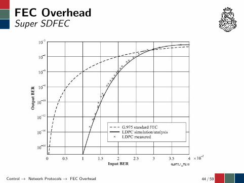
FEC OverheadSuper SDFEC
Control → Network Protocols → FEC Overhead 44 / 59

Outline
1 Network Management
2 Network ProtocolsAlignment OverheadFEC OverheadOTU OverheadODU OverheadOPU Overhead
Control → Network Protocols → OTU Overhead 45 / 59
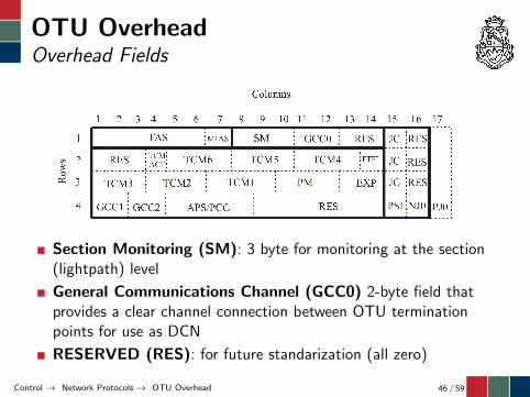
OTU OverheadOverhead Fields
Section Monitoring (SM): 3 byte for monitoring at the section(lightpath) level
General Communications Channel (GCC0) 2-byte field thatprovides a clear channel connection between OTU terminationpoints for use as DCN
RESERVED (RES): for future standarization (all zero)
Control → Network Protocols → OTU Overhead 46 / 59

Section MonitoringOverhead Fields
Control → Network Protocols → OTU Overhead 47 / 59

Section MonitoringOverhead Fields
Trail Trace Identifier (TTI) 64 bytes for lighpath identificationdistributed over 64 frames (1 byte on each frame), where 16bytes are used for endpoint ids and the remaining 32 bytes areoperator specific
BIP-8 Parity checksum to detect errored frames (i.e., blocks)
Alarm signals
BEI/BIAE (backward error indicator and backward incomingalignment error) indicates to upstream node the number of erroredblocks (BIP-8 fails) or if there is an incoming alignment errorBDI (backward defect indication (BDI) indicates to upstreamnode whether there is a signal defectIAE (incoming alignment error) indicates to downstream nodethat it has detected an alignment error
Control → Network Protocols → OTU Overhead 48 / 59

Section MonitoringTrail-trace Identifier Mismatch (TIM)
The TTI mismatch process reports the trail trace identifiermismatch defect (TIM)
The process is based on the comparison of expected xAPIs (i.e.,SAPI and DAPI) with the xAPIs in the incoming signal.
An acceptance process is required to define the xAPI values onthe incoming signal, which typically is based on receiving 3consecutive times the same value
Control → Network Protocols → OTU Overhead 49 / 59
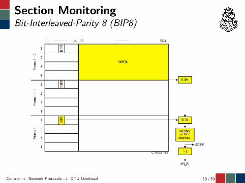
Section MonitoringBit-Interleaved-Parity 8 (BIP8)
Control → Network Protocols → OTU Overhead 50 / 59

Section Monitoring(Backward) Incoming Alignment Error)
Control → Network Protocols → OTU Overhead 51 / 59

Outline
1 Network Management
2 Network ProtocolsAlignment OverheadFEC OverheadOTU OverheadODU OverheadOPU Overhead
Control → Network Protocols → ODU Overhead 52 / 59
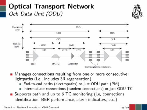
Optical Transport NetworkOch Data Unit (ODU)
Manages connections resulting from one or more consecutivelightpaths (i.e., includes 3R regeneration)
End-to-end paths (electropaths) or just ODU path (PM)Intermediate connections (tandem connections) or just ODU TC
Supports path and up to 6 TC monitoring (i.e, connectionsidentification, BER performance, alarm indicators, etc.)
Control → Network Protocols → ODU Overhead 53 / 59

Path & TC MonitoringOvehead Fields
Control → Network Protocols → ODU Overhead 54 / 59

Och Data Unit (ODU)Maintenance Signals
A status field (STAT) is used to indicate the presence of amaintenance signal
ODU-AIS: an alarm indication signal (AIS) is a signal sentdownstream as an indication that an upstream defect has beendetected. Encoded as all 1s signal.ODU-OCI: an open connection indication (OCI) is a signal sentdownstream as an indication that upstream the signal is notconnected (i.e., provisioned) Encoded as 0110 signal.ODU-LCK: a locked signal is sent downstream as an indicationthat upstream the connection is ”locked”, and no signal haspassed through. Encoded as 0101 signal.
Control → Network Protocols → ODU Overhead 55 / 59

Outline
1 Network Management
2 Network ProtocolsAlignment OverheadFEC OverheadOTU OverheadODU OverheadOPU Overhead
Control → Network Protocols → OPU Overhead 56 / 59

Optical Transport NetworkOch Paylod Unit (OPU)
Adapts client signals to the OTN frames
Control → Network Protocols → OPU Overhead 57 / 59

Optical Transport NetworkOPU Fields
One-byte Payload Type (PT) is used to indicate the content ofthe OPU signal
Control → Network Protocols → OPU Overhead 58 / 59
Optical Network Control
Jorge M. Finochietto
Cordoba – 2014
LCD EFN UNCLaboratorio de Comunicaciones DigitalesFacultad de Ciencias Exactas, Físicas y NaturalesUniversidad Nacional de Córdoba, Argentina