optical pufs reloaded - cryptology eprint archive pufs reloaded ulrich rührmair computer science...
TRANSCRIPT

Optical PUFs Reloaded
Ulrich RührmairComputer Science Dept.
TU München80333 München, [email protected]
Christian HilgersComputer Science Dept.
TU München80333 München, Germany
Sebastian UrbanComputer Science Dept.
TU München80333 München, [email protected]
Agnes WeiershäuserComputer Science Dept.
TU München80333 München
Elias DinterComputer Science Dept.
TU München80333 München
Brigitte ForsterFIM
Universität Passau94032 Passau, Germanybrigitte.forster@uni-
passau.de
Christian JirauschekElectrical Engineering Dept.
TU München80333 München, [email protected]
ABSTRACTWe revisit optical physical unclonable functions (PUFs), which wereproposed by Pappu et al. in their seminal first publication on PUFs[40, 41]. The first part of the paper treats non-integrated opticalPUFs. Their security against modeling attacks is analyzed, and wediscuss new image transformations that maximize the PUF’s out-put entropy while possessing similar error correction capacities asprevious approaches [40, 41]. Furthermore, the influence of us-ing more than one laser beam, varying laser diameters, and smallerscatterer sizes is systematically studied. Our findings enable thesimple enhancement of an optical PUF’s security without addi-tional hardware costs. Next, we discuss the novel application ofnon-integrated optical PUFs as so-called “Certifiable PUFs”. Thelatter are useful to achieve practical security in advanced PUF-pro-tocols, as recently observed by Rührmair and van Dijk at Oakland2013 [48]. Our technique is the first mechanism for CertifiablePUFs in the literature, answering an open problem posed in [48].
In the second part of the paper, we turn to integrated opticalPUFs. We build the first prototype of an integrated optical PUFthat functions without moving components and investigate its se-curity. We show that these PUFs can surprisingly be attacked bymachine learning techniques if the employed scattering structure islinear, and if the raw interference images of the PUF are availableto the adversary. Our result enforces the use of non-linear scatteringstructures within integrated PUFs. The quest for suitable materials
Permission to make digital or hard copies of all or part of this work forpersonal or classroom use is granted without fee provided that copies arenot made or distributed for profit or commercial advantage and that copiesbear this notice and the full citation on the first page. To copy otherwise, torepublish, to post on servers or to redistribute to lists, requires prior specificpermission and/or a fee.Copyright 200X ACM X-XXXXX-XX-X/XX/XX ...$10.00.
is identified as a central, but currently open research problem. Ourwork makes intensive use of two prototypes of optical PUFs. Thepresented integratable optical PUF prototype is, to our knowledge,the first of its kind in the literature.
Categories and Subject DescriptorsB.0 [Hardware]: General; C.3 [Special Purpose and Application-Based Systems]: Smartcards
KeywordsOptical Physical Unclonable Functions (PUFs), Machine Learning,Implementation
1. INTRODUCTIONMobile security devices have become ubiquituous in our life.
Their widespread use makes them an attractive and accessible tar-get for adversaries. The majority of known attacks are thereby notdirected against the employed cryptographic primitives themselves.Rather, they often attempt to obtain the used secret keys by physicaltechniques or malware. Such key-extracting strategies are not justa theoretical concern, but have been demonstrated several times inwidespread, commercial systems [30, 14, 1]. The fact that the se-curity devices shall be inexpensive aggravates the problem, leavinglittle room for elaborate key protection measures.
The described situation was one motivation that led to the de-velopment of Physical Unclonable Functions (PUFs). A PUF isa (partly) disordered physical system that can be challenged withso-called external stimuli or challenges Ci, upon which it reactswith corresponding responses Ri. The tuples (Ci, Ri) are therebyoften called the challenge-response pairs (CRPs) of the PUF. Theresponses Ri shall be a function of the applied challenge and themicro- or nanoscale structural disorder present in the PUF. It is as-sumed that this disorder cannot be cloned or reproduced exactly,not even by the PUF’s original manufacturer. Due to its complex

internal structure, it is usually harder to read out, predict, or de-rive the responses of a PUF than to obtain digital keys stored instandard non-volatile memory. This can make PUF-based systemsmore resilient against hardware and malware attacks than classicalapproaches.
PUFs can be used in various cryptographic and security applica-tions. Examples include their employment as tamper sensitive se-cret key storage [59, 23, 19, 58], or their use as a complex identifierfor a hardware system that embeds the PUF [40, 41, 18, 58]. Recentresearch has also discovered their application in more complex pro-tocols such as oblivious transfer, bit commitment, key exchange, ormulti-party computation [42, 3, 38]. The practical security of thelatter protocols has been discussed intensively in an attempt to keepPUF theory and PUF applications closely together [46, 47, 48].
On the implementation side, most recent research has focused onelectrical PUFs. The most common types include SRAM PUFs andvariants thereof [23, 27, 31, 55], the Arbiter PUF and its variousmodifications [18, 58, 51, 34, 19, 33], and Ring Oscillator PUFs[58]. Other examples include Crossbar PUFs [45, 49], analog PUFsbased on cellular non-linear networks [9], or the Bistable Ring PUF[5, 6]. Several of these electrical PUFs have been attacked by ma-chine learning based modeling attacks [51, 53], however, and alsosuccessful cloning attacks on certain types of electrical PUFs havebeen reported recently [25].
Optical PUFs.Under their original name “Physical One-Way Functions (POWFs)”,
the optical systems proposed by Pappu et al. [40, 41] were one ofthe first suggested PUFs. In their original, non-integrated form,they possess several advantages:
• Low costs per piece: A non-integrated optical PUF merelyconsists of an inexpensive plastic platelet with randomly dis-tributed light scatterers inside. No microelectronic or siliconcircuitry on the PUF-carrying object is required.
• High output complexity: Each PUF-response consists of thou-sands of bits, and results from a very complex optical inter-ference process inside the token.
• High security against modeling attacks (compare [51, 53] forsuch attacks on certain types of electrical PUFs). No similarattacks on non-integrated optical PUFs are known to date.
• High security against physical cloning attacks (compare [25]for such attacks on certain types of electrical PUFs). No suchattacks on non-integrated optical PUFs have been reported.
• Non-integrated optical PUFs are suited as “Certifiable PUFs”.It can be proven within certain limits that they have not beenmodified or exchanged by malicious parties (see Section 6).
On the downside, non-integrated optical PUFs à la Pappu et al.require an optical precision mechanism for read-out [40, 41]. Thismechanism must establish exactly the same relative positioning ofthe light scattering token, the laser beam, and the CCD camera uponevery single read-out. Its implementation is expensive and poten-tially error prone. This downside is hard to overcome, as Pappu etal.’s initial construction cannot be integrated or miniaturized easily.
Related Work and Our Contributions.Despite their advantages, there has been surprisingly little activ-
ity on optical PUFs in recent years. Two examples are Tuyls et al.[63], who investigate the information content of optical PUFs, andTuyls and Skoric [61], who briefly discuss integrated optical PUFs
in theory, but present no experimental prototypes or security anal-yses [61]. A further, general source is [62]. Perhaps more activityon the security use of scattering phenomena has recently occuredin a related, but not identical area. In this strand, the complex pat-terns emerging from laser-illuminated paper surfaces are used toauthenticate objects, products, packages, documents, or digital con-tent. Recent works on this topic have appeared in the Nature maga-zine [4], the IEEE Security and Privacy Symposium [8], ACM CCS[54], and other venues [57]. Furthermore, authors have suggestedat CHES 2009 [24] and FC 2009 [65] how the digital content storedon compact discs can be authenticated by exploiting the individualscattering behavior of each disc.
Within this research landscape, we make the following contri-butions. Firstly, we investigate the optimized implementation ofoptical PUFs. We describe how their output complexity and secu-rity can be enhanced by simple measures such as varying the laserdiameter or choosing the right size of the light scattering elements.Application of this technique allows us to increase the number ofeffectively independent CRPs of our non-integrated optical PUFprototype by a factor of around 24, without causing substantial ad-ditional costs. Secondly, we observe that the Gabor image trans-form applied by Pappu et al. [40, 41] leads to strong regularities inthe derived cryptographic keys. We present a number of alternativetransformations, showing that they can enhance the estimated re-sponse entropy by a factor of almost four. Our new transformationscan be used with great benefits in any security application that ex-ploits optical scattering phenomena, including the abovementionedapproaches [4, 8, 54, 57].
Thirdly, we suggest that non-integrated optical PUFs could beused as so-called “Certifiable PUFs”. As described recently at Oak-land 2013 [48], Certifiable PUF are useful, and in a certain senseeven necessary, to implement secure and practical PUF protocolsfor advanced cryptographic tasks like oblivious transfer. We de-scribe a method for the offline certification of non-integrated opti-cal PUFs at low costs. Our suggestion is the first construction forCertifiable PUFs in the literature.
In the second part of the paper, we investigate integrated opticalPUFs. We build a first prototype and evalute its security. One sur-prising result is that integrated optical PUFs can be machine learn-ing successfully if linear optical scattering structures are used, andif the adversary can access the raw scattering images before theyare postprocessed. The quest for suited non-linear optical materialsis identified as a central open research problem.
In all our analyses, real experimental data from two prototypesis used: A non-integrated optical PUF à la Pappu et al. [41, 40],and an integratable optical PUF constructed from inexpensive con-sumer components. Our integrated PUF prototype is the first of itskind in the literature. It functions without moving components andpossesses an exponential number of challenges.
Organization of this Paper.The first part of the paper deals with non-integrated optical PUFs:
Section 2 describes our experimental set-up for this PUF-type. Sec-tion 3 discusses their security against modeling attacks. Sections 4and 5 optimize their output complexity by tuning the laser diameter,scatterer size, and employed image transformations, respectively.Section 6 describes their use as Certifiable PUFs. Subsequently weturn to integrated optical PUFs: Section 7 details our experimentalprototype of an integrated optical PUF. Section 8 reports modelingattacks on this PUF-type. We conclude the paper in Section 9.

Laser beam
Scattering token
(in positioning system)Numerical image
transformation
„Raw“ interference pattern
(recorded by CCD)
Bitstring
1010101101011
Figure 1: Schematic illustration of our implementation of a non-integrated PUF à la Pappu et al. [40, 41] (“Pappu’s PUF”), and thenecessary postprocessing for the derivation of the PUF response. As shown, we measure the intrference pattern (often also called“speckle pattern”) in transmission, whereas Pappu et al. [40, 41] measure it in reflection. A numerical image transformation isusually applied to obtain the eventual PUF response.
2. IMPLEMENTATION OF NON-INTEGRA-TED OPTICAL PUFS
In our implementation of non-integrated optical PUFs, we em-ployed a slightly modified version of Pappu et al.’s original set-up[40, 41]. Instead of measuring the reflected light as in [40], we de-tect the speckle pattern in transmission of the light through the op-tical PUF. The new set-up enabled simpler and more cost-effectiverealizations and thus seemed preferrable. Note that said modifica-tion does not affect the PUF’s input-output complexity in any way.The schematics of our set-up are given in Figure 1. A challenge Ci
to this PUF consists of a specific point and angle of incidence ofthe applied laser beam. The corresponding response Ri of the PUFis the result of an image transformation applied to the raw specklepattern captured by the CCD camera. Pappu et al. apply the Ga-bor transformation to this end [40, 41], but several alternatives arepossible (see Section 5).
As light source we used a red Lasiris SNF Laser with a wave-length of 635 nm and a power of less than 5 mW. The distancebetween the laser and the probe is about 980 mm. The integratedoptic of the laser is adjustable, which enables the focussing of thelaser beam. The optical interference pattern or “speckle pattern” ofthe transmitted laser light is captured with a MV-D1024E camerafrom Photonfocus. The distance between the PUF and the cameralens is 26 mm. The integrated CMOS sensor of the camera preventsthe common CCD blooming effects. For our experiments we tookeight bit gray scale images with a resolution of 1024x1024 pixels.To apply different challenges to the PUF, we used a positioning sys-tem for moving and rotating the scattering token. The positioningsystem is based on three stepper motors. We used two linear tablesof type LM 45 for horizontal and vertical movements and also oneMOGO 40 to adjust the angle of the scattering token. With thissystem we can move the optical PUF about 12 mm in vertical andhorizontal direction. We can rotate the PUF, and thus change theangle of incidence of the laser beam, by about ± 15◦.
The scattering tokens were prepared by distributing glass spheresof a certain size range randomly in a transparent matrix material.Various size ranges have been examined in our experiments: Weused glass spheres from Mühlmeier in the ranges 400-600µm and300-400µm, and from Worf Glaskugeln in the ranges 250-420µm,105-210µm, 90-106µm, and 40-80µm. From the tested matrix ma-terials, the consumer glue UHU Plus Schnellfest was simpler tohandle and led to better results than the more expensive optical ad-hesive NOA 61 from Norland. For the manual preparation of of thetokens, we used the following method: We applied the glue on a
glass slide and scattered the glass spheres in a dense layer. After ashort drying time, we apply the next layer of glue and glass spheres.Depending on the size of the spheres, we varied the number of lay-ers between four and five, resulting in equally sized tokens of ca.1cm×1cm×2.5mm.
Read-Out Stability of Our Set-Up.To evaluate the stability of our set-up, we used our above po-
sitioning system to apply the same challenge C0 twice, but posi-tioned the system to some intermediate challenge CI in betweenthe two measurements for C0. Due to inaccuracies in the stepmotors, the re-positioning to challenge C0 is prone to small er-rors. After application of the Gabor transformation the observednoise level (measured in the hamming distance of the two obtainedGabor-transformed images for the challenge C0) was about 6%.This noise level poses no problem to practical applications (com-pare Pappu et al. [40, 41]).
3. SECURITY OF NON-INTEGRATED OP-TICAL PUFS
While successful modeling attacks have been published on sev-eral electrical PUFs [51, 53], no such attacks have ever been re-ported on non-integrated optical PUFs. We re-investigated the hard-ness of this problem, and collected 100,000 raw speckle imagesfrom each of three different scattering tokens, using our set-up ofthe last section. The images were generated by dividing the x- andy-axis into in 317 equal segments and by moving the laser beam tothe resulting grid points, using a fixed laser angle. We then consid-ered in theory and/or practice the applicability of machine learn-ing (ML) algorithms to this data, including those techniques usedin earlier attacks on electrical PUFs [51, 53]. All of our effortsremained unsuccessful, however. For example, the application ofSupport Vector Machines with linear kernels to predict single bitsof the raw optical PUF output led to error rates around 50%, i.e., theprediction quality was essentially equal to random guessing [13].
There are three main theoretical reasons for the practical failureof any investigated ML method on non-integrated optical PUFs.The first is their large information content. As argued in [41], everyvolume unit of size around the laser wavelength of around 600 nmin principle can have an influence on the scattering process. Giventhe size of our tokens, in theory up to 1011 volume units wouldhave to be considered. Even though this figures represent the ex-treme, theoretical case, also in practice the ML feature vectors aretoo large to be handled well. In opposition, the ML problems for

a) b)
Figure 2: Decorrelation speed of the PUF output for horizontal and rotational shifts of the laser beam, as a function of different laserdiameters. A fractional Hamming distance of 0.5 indicates full decorrelation between the two outputs. Smaller laser diameters causefaster decorrelation for horizontal shifts, but slower decorrelation for changes in the laser angle. A token with scatterers in the sizerange of 300-400µm was used.
known electrical PUFs lead to much smaller feature vectors: a 128-bit Arbiter PUF, for example, has an associated feature vector withonly 129 entries [51, 53].
A second reason is the complex optical interference process in-side optical PUFs. For all methods known to us, exact simulationis too laborious to be carried out in practice (compare Section 4.3).This prevents the application of ML techniques that require suchsimulation in the evaluation of the so-called “fitness” of a givenML feature vector. It rules out so-called “Evolution Strategies”and related methods, which had been applied successfully to elec-trical PUFs in the past [51, 53]. In comparison, the internal mech-anisms of current electrical PUFs can often be described by sim-plified models, such as the well-known linear additive delay modelin the case of Arbiter PUFs [51, 53]. The decisive feature of opti-cal systems here seems that the massless photons facilitate a verycomplex scattering interaction, which is yet stable against varyingambient conditions, and does not alter or wear off the PUF inter-nally. The same effect seems hard to obtain for electrical structures.
Finally, in theory each PUF-challenge should illuminate the en-tire scattering token. We observed that this is not the case in prac-tice, however. The incident laser causes a light cone inside thetoken, meaning that for different PUF-challenges different and in-dependent regions of the token are illuminated predominantly andcause the respective responses. This independence complicates oreven directly prevents straightforward forms of modeling attacks.In addition, the vast number of different laser positions prohibitsthat the PUF output is modeled by some simple form of superposi-tion of known signals, as it is the case for integrated optical PUFs(see Section 8). No comparable simplifications could be derived byus for non-integrated optical PUFs. Taken together, these factorsresult in an unprecedented level of security of non-integrated PUFsagainst modeling attacks.
4. ENHANCING THE CHALLENGE SPACEAND SCATTERING COMPLEXITY
Pappu et al. report that their non-integrated optical PUF pos-sesses around 2.37× 10¹⁰ challenges for which the correspondingGabor-tranformed responses are virtually independent and decor-related. Given its high resilience against modeling (see Section3), this makes a complete read-out the currently most viable attackstrategy on this PUF type. The relatively small size of the challengespace is also exploited in a number of recent quadratic attacks onPUF protocols reported at CHES 2012 and in the Journal of Cryp-
tographic Engineering 2013 [46, 47]. In this section, we thereforesystematically investigate methods to increase the number of decor-related CRPs. The measures we discuss in Sections 4.2 and 4.3 areparticularly inexpensive and simple to realize.
4.1 Influence of Multiple Laser BeamsOne seemingly straightforward step to raise the size of the chal-
lenge space is to use several lasers beams with different frequen-cies, for example one red and one green laser. Due to the differingwavelengths, the interference pattern resulting from a green laserincident at point p⃗ and angle Θ differs from the pattern resultingfrom a red laser incident at exactly the same point and angle. Ithence seems suggestive to use two such lasers, and to define onePUF challenge Ci to consist of the incidence points p⃗ and angles Θof both lasers, i.e., Ci := (p⃗red,Θred; p⃗green,Θgreen). This promisesto quadratically enhance the size of the challenge space. Similarsuggestions have been existent as folklore in the community forsome time.
There is a problem with this approach, however, as long as linearscattering structures are used. In this case, the interference pat-tern resulting from the challenge Ci = (p⃗red,Θred; p⃗green,Θgreen)is nothing else than the sum of the two patterns resulting from thechallenges Cred
i = (p⃗red,Θred) and Cgreeni = (p⃗green,Θgreen). More
precisely, the intensity in each CCD pixel for the challenge Ci isexactly equal to the intensity resulting from challenge Cred
i plus theintensity resulting from challenge Cgreen
i . A second reason for thissimple behavior is that the red and green light are not coherent aslong as two separate standard lasers are used. No complex inter-ference process can take place, and the resulting intensities simplyadd up in the CCD image.
This allows a simplified full read-out of the above type of PUFthat possesses a red and green laser as follows: The adversary firstreads out the interference patterns for all challenges from the redlaser alone, then for all challenges from the green laser alone. Sub-sequently he can derive the patterns for all combined challengesCi = (p⃗red,Θred; p⃗green,Θgreen) by simply adding the known pat-tern from the challenge Cred
i = (p⃗red,Θred) to the known patternfrom challenge Cgreen
i = (p⃗green,Θgreen). Using two lasers henceeffectively increases the challenge space only by a factor of abouttwo. On the other hand, however, it results in a significantly in-creased implementation effort, as the two lasers need to be posi-tionable independently from each other. A further practical aspectis that in Pappu et al.’s and our set-up, the scattering token is made

a) b)
Figure 3: Decorrelation speed of the PUF output for variation of the incidence point and angle of the laser, and for different scatterersizes. Scatterers in an overall range from 400µm to 40µm were examined. Smaller scatterers lead to faster decorrelation.
positionable and the laser is immobile. The simple reason is thatthe laser is much larger and heavier. With two lasers that shall gen-erate independent challenges, this method is no longer applicable.Similar considerations hold for the case of k lasers.
To summarize, using k laser beams with a linear scattering medi-um only increases the effective challenge space by a factor of k,but is very expensive. Better methods are discussed over the nextsubsections.
4.2 Influence of the Laser DiameterNext, we investigated the sensitivity of the PUF-output in depen-
dence of the laser diameter to (i) variation of the point of incidenceof the laser in the x-y-directions, and to (ii) alteration of its in-cidence angle. This sensitivity is a good measure for an opticalPUF’s security: It determines the number of virtually independentchallenge-response pairs of the PUF, and thus its resilience againstfull read-out attacks.
In the set-up of Figure 1, the laser diameter can be adjusted bysimply focusing the laser. The focal point lies beyond the entrancepoint of the PUF, and we measured the effective laser diameter atthe entrance point. During our experiments we used a PUF withfive layers and 300-400µm glass spheres. During the experiment,we move the PUF by the positioning system in equally spaced shiftsand take pictures of the speckle patterns. The center position of thetoken was chosen as reference position. For all measured raw im-ages, we then computed the Gabor transformed images as in [40,41]. We determined their fractional Hamming distances 1 to the Ga-bor image of the reference position. A fractional Hamming distanceof 0.5 signals a virtual decorrelation between the Gabor images.
Figures 2a and b depict our findings. For each shown curve, thecritical parameter is how quickly the curve not reaches, but settlesat the 0.5-level of the fractional Hamming distance. The faster thisoccurs, the more virtually independent and decorrelated challenge-response pairs of the PUF exist. The presented data illustrates thatsmaller diameters lead to faster decorrelation for horizontal (andalso vertical) movements, but slower decorrelation in the rotationalmovement. This turns the choice of the optimal laser diameter intoan optimization problem. In practice, its solution depends on theexperimental set-up and the used materials in the scattering token.It must thus be solved in each application of optical PUFs empiri-cally by the above method to achieve optimal security. In our case,
1The fractional Hamming distance of two bitstrings of the samelength l is the number of all bits on which the two strings differdivided by the length l of the string(s).
laser diameters between 1.5 mm and 2.5 mm were optimal. Es-timating from the above diagrams, we conclude that the optimallaser diameter (in comparison to a non-optimal diameter of 5.0mmor larger) can increase the effective challenge space by a factor ofaround 3 to 5.
4.3 Influence of the Scatterer SizeWe also systematically investigated the influence of the scatterer
sizes. From theoretical considerations, an optimal complexity ofthe scattering process can be expected for a size similar to the wave-length of the used laser light. In this case, which is also referred toas Mie-regime [36, 11, 28], the interference pattern critically de-pends on the particle sizes and shapes. The resulting electromag-netic field distribution within the PUF can only be adequately de-scribed by exactly solving the Maxwell equations, which is numer-ically very demanding. For particle sizes significantly larger thanthe optical wavelength, simplified methods such as ray tracing ap-proaches become valid [20], which avoid the numerical complexityinvolved in solving the full Maxwell equations. On the other hand,for particles or refractive index inhomogeneities on a length scalesignificantly smaller than the wavelength, the scattered light fieldcan be described by an approximation to the Mie solution, the muchsimpler Rayleigh scattering [28]. In the extreme case of a large en-semble of far sub-wavelength objects, the single scatterers cannotbe optically resolved at all. The medium is then comprehensivelydescribed by a volume-averaged effective refractive index, againexhibiting low optical complexity.
This suggests that for our red laser of wavelength 635nm, par-ticles of approximately the same sizes should be used to facilitatemaximally complex scattering phenomena. Note that this is abouta factor of 1,000 smaller than the sizes used by Pappu et al. in theiroriginal experiments [40, 41]. The experimental exploration of thisregime requires nanofabrication techniques, which we did not haveavailable at the time of writing. In order to lead at least a quali-tive proof of concept that optical PUFs become increasingly com-plex for smaller scatterers, we carried out experiments with sizeranges 400-600µm, 250-420µm, 105-210µm, and 40-80µm (com-pare Section 2). These could be handled by our manual fabricationmethods. The particles we used are still up to a factor of ten smallerthan the scatterers employed by Pappu et al. [40, 41].
As formal measure for the resulting internal complexity of thescattering process, we used again the sensitivity of the speckle pat-tern against variations in the laser coordinates and angles. We de-termined how quickly the transformed images decorrelate in prac-

Gabor, Version 1 Adapted High-BoostGabor, Version 2 B-Splines
Figure 4: Images obtained from different image transformations. The two leftmost images are obtained from the Gabor transfor-mation for different parameters, illustrating the typical, zebra stripe like regularities. The two right images are obtained from ouradapted high-boost transformation and from B-spline wavelets. They cause considerably less regularities.
tice, depicting our findings in Figure 3. They confirm that in thelength regimes examined by us, the internal complexity steadilyincreases for smaller scatterers. They also show that the effectivechallenge space can be increased by choosing smaller scatterers.Extrapolating from our above diagrams, using scatterers of size 40-80µm instead of 500-800µm as in Pappu et al. [41, 40] improvesthe size of the challenge space by about a factor of two in the hor-izontal directions, and the same in the vertical direction and forvarying angles. This will lead to an overall improvement of a factoraround eight. Probably yet better improvements could be achievedin the nano-regime.
Our conclusion is that the use of small scatterers is a very simpleand inexpensive means of increasing the security of optical PUFs.In practical applications, they should hence be chosen as small aspossible under the given fabrication, cost, and stability constraints.
5. ENHANCING RESPONSE ENTROPYAs already noted by Pappu et al. [40, 41], the “raw” optical inter-
ference images (as recorded by a CCD camera) should not be useddirectly as response of an optical PUF, as they are too large and un-stable. A numeric transformation must be applied to distill shorter,more stable bitstrings. Pappu et al. utilize the well-established Ga-bor transform to this end. This transformation is applied to theraw CCD images, and the resulting the two-dimensional Gabor-transformed images (after a threshold step for conversion into bi-nary data) are subsequently be converted into a cryptographic keyby simply reading out the transformed images line by line.
There are, however, two downsides of this approach. The Ga-bor transformed images have very strong, zebra-stripe like regular-ities (see Figure 4). These regularities cause strong patterns in thecryptographic keys, i.e., they lead to regularly alternating, medium-length sequences of consecutive ones and zeros in the keys. Sec-ondly, since the Gabor images do not contain maximal entropy(as they exhibit said patterns), they do not reflect the small-scalephysical randomness of the optical PUF in an optimal way. Thismakes it in principle easier to build PUFs with the same challenge-response behavior. In order to achieve a maximal security levelagainst cloning, an optimal bitwise entropy in the PUF responsesshould be achieved.
The problem of regularities in the Gabor images has also beenobserved in [60]. As a countermeasure, the authors propose tochoose a random subset of the bits of the Gabor image. However,their positions of these bits need to be stored together with the bitvalues themselves, increasing storage requirements. Furthermore,it is non-trivial how to select bits that are stable and carry a largeamount of information at the same time. Finally, the method does
not address the problem that much information about the unclon-able random structure is wasted by the Gabor transform. Instead ofapplying some postprocessing to the Gabor transform, we believethat a better approach is to use alternative image transformationsfrom the start.
From theoretical considerations [10], so-called wavelet transfor-mations seemed good candidates, since they induce less structurein the transformed image. We empirically tested a considerablenumber of transformations from this family for their practical per-formance on optical PUFs, including Daubechies wavelets [10],symlets [10], polyharmonic isotropic B-spline wavelets [64] andquincunx wavelets based on on the McLellan transformation [15].We empirically optimized the exact parameters of the transforma-tions during our experiments. As expected, all tested transforma-tions could significantly increase the bitwise entropy of the PUF re-sponses, with the B-spline wavelets being best in class. All of themexhibited slightly worse robustness than the Gabor-transformation,however. Even with our relatively inexpensive set-up and step-per motors, this posed no practical problem. But in order to beequipped for any type of application scenario, we devised a newtransformation in-house [26]. It realizes essentially the same sta-bility level as the Gabor transformation, but still causes much lessregularities in the transformed images.
In our method, which we call adapted high-boost transform (AHB),we used a convolution kernel, which compares the intensity of apixel against its neighborhood. As in the Gabor transformation, theconversion into a binary key is accomplished by a threshold filter.The method calculates the arithmetic mean of the intensity of pixelsin the neighborhood of a center pixel. If the intensity of the centerpixel plus an adjustable offset is smaller than the arithmetic mean,the pixel is set to “1”, otherwise to “0”.
In practice, this can be implemented with a simple convolutionmatrix A and a threshold t. For the case of a 3×3 matrix the con-volution kernel is a 2D Laplace filter which also response to 45◦
edges. The definition for a n× n convolution kernel A is given as:
A =
1 1 · · · 1 · · · 1 1...
.... . . 1
. . ....
...1 1 · · · −n2 + 1 · · · 1 1...
.... . . 1
. . ....
...1 1 · · · 1 · · · 1 1
n
︸ ︷︷ ︸n
The binary key of speckle image I(u, v) can be extracted byreading the binary image B(x, y) line by line. We obtained the

best results by a 7×7 convolution matrix. Filters comparable toours have been termed “high-boost” in [22], hence the name AHB.
B(x, y) =
{1, if
∫v
∫uI(u, v) ·A((x− u), (y − v)) du dv > t
0, if∫v
∫uI(u, v) ·A((x− u), (y − v)) du dv ≤ t
Before the convolution matrix is applied, the picture can be scaledto a desired size. The number of scales gives, as in the Gabor trans-formation, the level of the transformation. The scaling algorithmhas a significant effect on the robustness and information density.The implementation was realized with the OpenCV with a pixelarea relation, which is the preferred method for image decimationthat gives Moiré-free results [37].
Figure 4 qualitatively illustrates the difference in entropy andrandomness for the applied image transformations, which is al-ready visible well by the sheer eye. A more quantitative analy-sis can be obtained by applying a procedure already suggested byPappu et al. (compare [41] and section 8.1 of [40]): One collectsa large sequence of transformed images (for m randomly chosenchallenges, say), and compares the statistical variance to the vari-ance that would have occured if the sequence would have been gen-erated by an ideal binomial distribution of length k. As argued byPappu et al. [40, 41], this can be used as an estimator for the numberof independent bits. We applied this procedure to our case, collect-ing 400 transformed images. The used challenges were distributedequidistantly over the token, and the angle of incidence was per-pendicular to the token surface. We obtained the results of Table1. They quantitatively underpin the significant improvement of ournew transformations.
IMAGE Gabor AHB B-SplinesTRANSFORM
ESTIMATED 25% 90% 94%INDEPENDENT BITS
Table 1: Quantitative comparison of image transformations.The number of independent bits is estimated by the methodof Pappu et al. [40, 41] (see above).
We stress again that the AHB transform has essentially the samerobustness as the Gabor transform. The B-splines exhibited betterstability than most other tested wavelet transformations, but slightyworse robustness than the Gabor transform and our AHB transform.Details are given in in Appendix A and Figure 7.
6. USE OF NON-INTEGRATED PUFS ASCERTIFIABLE PUFS
In a recent paper at Oakland 2013 [48], two new, practically rel-evant attack models on Strong PUF protocols have been discussed.In one of the new attack models, the so-called “bad PUF model”,malicious parties may replace PUFs by other, malicious hardwarewhich looks like a PUF from the outside, but possesses hidden extraproperties that allow cheating. This approach represents a practi-cally viable attack strategy as long as the PUF cannot be “certi-fied” or “attested” for being unmanipulated and benign. The at-tack method is most relevant for integrated electrical Strong PUFs,since they communicate with external parties merely via a digitalchallenge-response interface. What is behind the interface henceremains hard to detect or verify for users.
One specific example of bad PUFs are so-called “SimulatablePUFs”. These are hardware systems which look like a properPUF from the outside, but possess a simulation code by which the
manufacturer (or other malicious parties) can simulate the PUF-responses to arbitrary challenges. They can hence obtain chal-lenges without being in physical possession of the PUF. One wayof a realizing a simulatable bad PUF is to construct a hardware sys-tem that looks like an integrated electrical PUF from the outside,possessing a standard CRP interface. But internally, the systemgenerates the PUF-responses by use of a numerical pseudo-randomnumber generator or a pseudo-random function, whose secret seedis known to the manufacturer/the malicious party. The tacit use ofsuch simulatable bad PUFs can spoil the security of several PUFprotocols, for example schemes for oblivious transfer, as fully de-tailed in [48].
As a countermeasure, the authors of [48] propose the design anduse of “Certifiable PUFs”: These are PUFs for which it can beverified that they do possess (at least some of) the expected prop-erties, for example, that they are unpredictable for all parties andthat they have not been manipulated or altered after their produc-tion. Up to this date, however, no strategies to “certify” PUFs inthe above sense have been proposed in the literature. Electricalintegrated PUFs seem very hard to certify in said manner, sincethey are accessed via a digital challenge-response interface (seeabove). Non-integrated optical PUFs show better potential, sincetheir complex analog responses are hard to imitate for maliciousPUFs, and are measured directly, i.e. not through any digital in-terface. We follow this line of thought and present below the firstscheme for the offline certification of non-integrated optical PUFs.It uses an oblivious transfer protocol of Rührmair and van Dijk asbasis, which employs interactive hashing as a substep (see [47] fordetails).
Protocol 1: SECURE OBLIVIOUS TRANSFER BASED ON CER-TIFIABLE OPTICAL PUFS
Set-Up Assumptions:
• The used optical PUF is fabricated by a manufacturer who istrusted by both the OT-sender and the OT-receiver.
• The manufacturer uses a digital signature scheme DSMan withsigning key SK and corresponding verification key VK.
• VK is known to both the OT-sender and the OT-receiver.
Pre-Protocol Steps:
• The manufacturer fabricates the optical PUF. He applies krandomly chosen challenges C1, . . . , Ck to the PUF, for kbeing a small, one-digit security parameter. He obtains theresponses R1, . . . , Rk.
• He generates the signature Sig := DSMan(C1, . . . , Ck, R1,. . . , Rk), and defines the certificate as
Cert := (C1, . . . , Ck, R1, . . . , Rk, Sig) .
• The PUF is distributed together with its certificate to the OT-receiver. In practice, the certificate can be stored inexpen-sively via a barcode, for example, which is printed on theitem in which the optical PUF is embedded.
Protocol:
Let the sender’s input be two strings s0, s1 ∈ {0, 1}λ and the re-ceiver’s input be a bit b ∈ {0, 1}. The protocol then proceeds asfollows:
1. The receiver verifies the certificate of the PUF. To that end,he applies the challengesC1, . . . , Ck to the PUF, and verifiesthat the obtained responses are equal to R1, . . . , Rk.
2. The receiver chooses a challenge c ∈ {0, 1}λ uniformly atrandom. He applies c to the PUF, obtaining the responser. He transfers the PUF together with the certificate to thesender.
3. The sender verifies the certificate of the PUF in the samemanner as above.
4. The sender and receiver execute an IH protocol, where thereceiver has input c. Both get outputs c0, c1. Let i be thevalue where ci = c.
5. The receiver sends b′ := b⊕ i to the sender.
6. The sender applies the challenges c0 and c1 to the PUF. De-note the corresponding responses as r0 and r1.
7. The sender sends S0 := s0 ⊕ rb′ and S1 := s1 ⊕ r1−b′ toreceiver.
8. The receiver recovers the string sb that depends on his choicebit b as Sb ⊕ r = sb ⊕ rb⊕b′ ⊕ r = sb ⊕ ri ⊕ r = sb.
The above certification step only works since the analog respon-ses of the PUF are measured by the involved parties themselves.The raw, two-dimensional speckle patterns are too complex to beimitated by a malicious, bad PUF. Therefore a verification of a verysmall number of sample CRPs suffices to exclude that the PUFhas been altered or exchanged against another PUF. The verifica-tion can be executed offline, i.e., without additional communicationwith the manufacturer. As already noted by Rührmair and van Dijk,this feature is essential: If an online communication with a trustedauthority would be a regular step in the protocol, then the OT couldbe executed much simpler via this trusted authority itself.
It is interesting to consider the above protocol under the aspectof the involved computational or other assumptions. The protocolrequires two assumptions: (i) an unpredictable PUF (see [43, 3]for formal definitions of the latter); (ii) a secure digital signaturescheme DSMan. It uses these two assumptions to implement OT.It is long known that secure digital signature schemes exist if andonly if one-way functions exist [21], but currently no constructionis known that implements OT merely from one-way functions. Theuse of unpredictable, certifiable PUFs hence is necessary and cre-ates additional value in the protocol.
The technique of digitally signing a unique, reflective specklepattern seems also promising in combination with future genera-tions of electrical Erasable PUFs [48, 44]. The speckle patterncould be recorded directly from the surface of the electrical PUF, oran optical encapsulation could be used that enables certification ofthe Erasable PUF inside. This eventually seems a promising tech-nique to finally realize PUFs that are both erasable and certifiable,as required in [48].
Example Implementation.We carried out an example implementation of certifiable optical
PUFs by use of 2D barcodes. We chose the libdmtx library [32] forthe implementation of the widely used Data Matrix Code. In orderto save area requirements for the barcode, our implementation isbased on the bilinear pairing based scheme by Zhang, Safavi-Nainiund Susilo (ZSS) [66]. For the implementation we chose the PBClibrary [39] with the elliptic curve type F and a signature of 200bits. We assumed that the following information must be stored on
the product: Manufacturer ID (16 bit), PUF ID (48 bit), Signature(200 bits), and image transformed speckle pattern. With a barcodemodule width of 0.25 mm this leads to a barcode of size on the or-der of 1 cm2. Barcodes of these sizes can easily and inexpensivelyaccompany optical PUFs in practice, for example on bank cards.
7. IMPLEMENTATION OF INTEGRATEDOPTICAL PUFS
One central, practically motivated research goal is to embed op-tical PUFs into microelectronic systems, i.e., to design secure inte-gratable optical PUFs. Pappu’s PUF is not very well suited to thisend, since it requires movable components that must be positionedwith high accuracy. A first miniaturized version of Pappu’s opticalPUF, which was briefly reported in [56], thus had to use expensivepiezo positioners. Such constructions can merely achieve compa-rably slow read-out speeds, and still exhibit a polynomial numberof challenges only, exactly like Pappu et al.’s original optical PUF.Are there other possibilities?
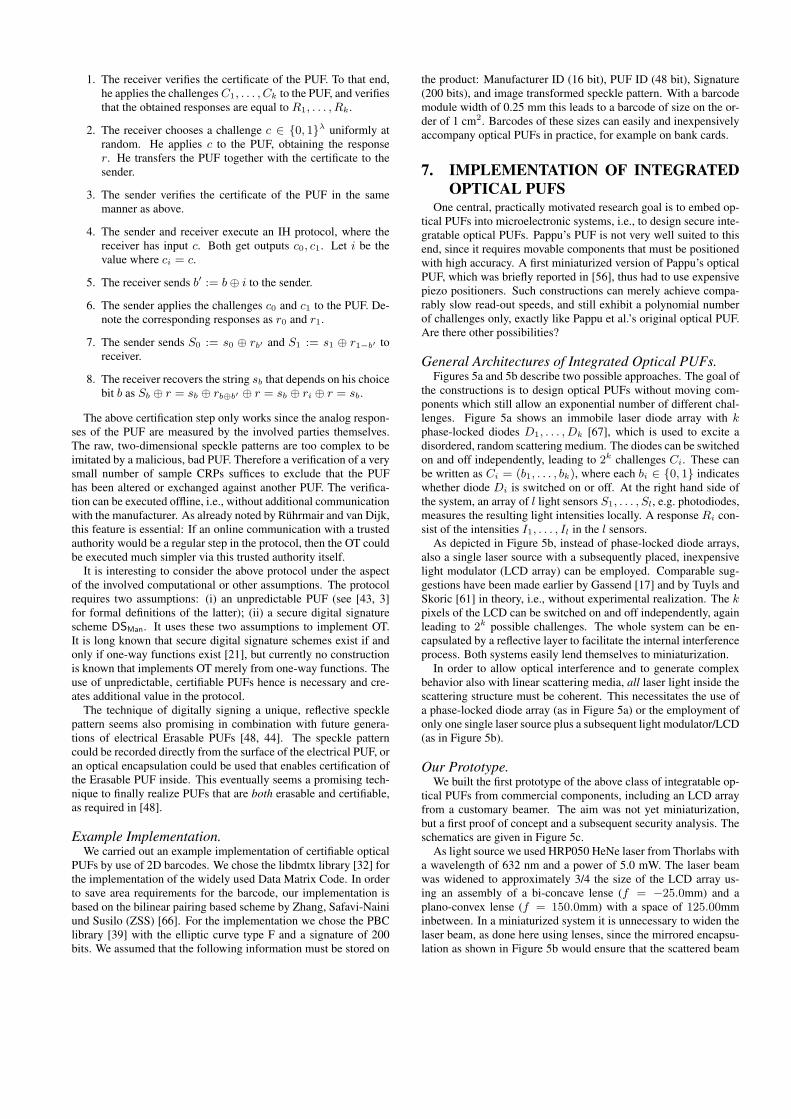
General Architectures of Integrated Optical PUFs.Figures 5a and 5b describe two possible approaches. The goal of
the constructions is to design optical PUFs without moving com-ponents which still allow an exponential number of different chal-lenges. Figure 5a shows an immobile laser diode array with kphase-locked diodes D1, . . . , Dk [67], which is used to excite adisordered, random scattering medium. The diodes can be switchedon and off independently, leading to 2k challenges Ci. These canbe written as Ci = (b1, . . . , bk), where each bi ∈ {0, 1} indicateswhether diode Di is switched on or off. At the right hand side ofthe system, an array of l light sensors S1, . . . , Sl, e.g. photodiodes,measures the resulting light intensities locally. A response Ri con-sist of the intensities I1, . . . , Il in the l sensors.
As depicted in Figure 5b, instead of phase-locked diode arrays,also a single laser source with a subsequently placed, inexpensivelight modulator (LCD array) can be employed. Comparable sug-gestions have been made earlier by Gassend [17] and by Tuyls andSkoric [61] in theory, i.e., without experimental realization. The kpixels of the LCD can be switched on and off independently, againleading to 2k possible challenges. The whole system can be en-capsulated by a reflective layer to facilitate the internal interferenceprocess. Both systems easily lend themselves to miniaturization.
In order to allow optical interference and to generate complexbehavior also with linear scattering media, all laser light inside thescattering structure must be coherent. This necessitates the use ofa phase-locked diode array (as in Figure 5a) or the employment ofonly one single laser source plus a subsequent light modulator/LCD(as in Figure 5b).
Our Prototype.We built the first prototype of the above class of integratable op-
tical PUFs from commercial components, including an LCD arrayfrom a customary beamer. The aim was not yet miniaturization,but a first proof of concept and a subsequent security analysis. Theschematics are given in Figure 5c.
As light source we used HRP050 HeNe laser from Thorlabs witha wavelength of 632 nm and a power of 5.0 mW. The laser beamwas widened to approximately 3/4 the size of the LCD array us-ing an assembly of a bi-concave lense (f = −25.0mm) and aplano-convex lense (f = 150.0mm) with a space of 125.00mminbetween. In a miniaturized system it is unnecessary to widen thelaser beam, as done here using lenses, since the mirrored encapsu-lation as shown in Figure 5b would ensure that the scattered beam

Light
scattering
medium
Sensor
array
Phase-locked
laser diodes
LCD arraySensor
array
Light reflecting
encapsulationSingle
laser
Light
scattering
medium
a) b) c)
CCD
CameraLaser
Plano-
convex lensLCD
Scattering
token
Bi-convex
lens
Bi-concave
lens
Figure 5: a) and b): Two possible theoretical types of integrated optical PUFs (compare [61, 17]). c): Schematic illustration of ourprototype (not true to scale).
eventually passes through the whole LCD array and scattering to-ken.
The widened beam was then modulated as it passed an LCD ar-ray, which had a resolution of 1024x768 pixels and was extracted,together with the associated control electronics, from a commer-cial Geha compact 640 LCD projector. Since the laser illuminatedonly 3/4 of the LCD array, approximately only 750x550 pixels wereuseable for the modulation of the beam. During initial testing wedetermined that flipping single pixels on the LCD did not resultin a significant change of the optical response as recorded by thecamera. Thus in order to get a detectable influence of each singlechallenge bit on the optical response we grouped adjacent pixelsinto blocks of 35 × 35 pixels. Hence the useable area of the LCDarray was divided into 15 × 15 = 225 rectangular blocks. The k-th block was associated with the k-th bit bk of the PUF-challenge.This bit determined whether all pixels of the whole k-th block wereswitched on or off. This methods leads to PUF-challenges Ci oflength 225 bits and a challenges space of 2225. As scattering ob-jects we used the same structures as in Section 2, specifically glassspheres by Mühlmeier with a size range of 300-400µm.
The modulated beam passes through the scattering structure andis then fed using a bi-convex lens (f = 25.4 mm) onto an EdmundOptics EO-0413BL Monochrome CMOS sensor with a resolutionof 752×480 pixels, where the response of the optical system isrecorded. Of those pixels an area of about 40,000 pixels were il-lumminated by the beam. As bleeding and overexposure lead tononlinearities, only 38,663 were used effectively.
The whole setup was controlled by a standard PC, and the LCDarray was driven using the VGA output port of the PC. We mea-sured that after a change of the VGA output signal the used LCDarray requires about 13ms until the new output is fully displayedand the picture is stable. In order to ensure that we do not recordthe output of the optical system while the LCD is still transitioningbetween the current and the previous challenge we always waited30ms before recording the optical response of a new challenge.
Read-Out Stability of our Set-Up.Similar as in Section 2, we investigated the read-out stability
of our prototype by applying a challenge C0 followed by an in-termediate challenge CI followed by switching back to C0. Wefound that even without subsequent error correction, the euclidiandistance dEuclidian(p, q) :=
√∑ni=1(qi − pi)2 in the raw speckle
images was on average only 0.80% per pixel (highest value here0.84% per pixel). This illustrates one first significant advantage of
integrated optical PUFs: As they have no moving parts, they canachieve unprecedented stability levels.
8. SECURITY OF INTEGRATED OPTICALPUFS
After our prototype was functional, we investigated the securityof integrated optical PUFs. We found that under the provision thata linear scattering medium is used in the integrated optical PUFsof Figure 5, the following analysis holds.
Consider that all blocks on the LCD array are turned off, so thatno light can pass through them, except the block correspondingto challenge bit bj , which is turned on. Then the electric field ateach detector cell i is the result of the laser beam passing throughLCD block bi and being scattered by the optical token. Thus theamplitude Ei of the electric field at the CMOS cell i is given by
Ei = Tijeiωt,
where Tij ∈ C. Since the optical medium is linear, the electricfields at the CMOS cells combine linearly if we turn on more thanone LCD block, thus we have
Ei =
N∑j=1
Tijbjeiωt,
where bj is 0 if block j is turned off and 1 if it is turned on. Thecorresponding intensities are given by
Ii = |Ei|2 = |N∑
j=1
Tijbj |2.
To faciliate linear learning, this can be written as
Ii =
N∑j=1
N∑k=1
TijT∗ikbjbk,
since bk ∈ {0, 1}. By defining the M × N2 matrix Ri,j·N+k =TijT
∗ik and the vector βj·N+k = bjbk with N2 elements, we can
rewrite the resulting intensities as
Ii =N2∑l=1
Rilβl , (1)
and thus we see that there is a linear relationship between the mea-sured pixel intensities on the CMOS sensor and the state of the

Challenge Predicted ResponseMeasured Response Difference Map
Figure 6: A randomly chosen 15 × 15 excitation pattern or challenge to the PUF; a CCD image of the response of the opticalintegrated PUF; the numerically predicted response; and the difference map between the latter two.
LCD blocks. To determine R we present l = 53701 randomlychosen challenges b⃗(n), n = {1, . . . , l} on the LCD and recordthe corresponding optical responses I⃗(n). During the recording ofthe reponses of some challenges some pixels of the CMOS sen-sors were overexposed or underexposed and thus the intensities Iireturned by the sensor for these pixels were clipped. We cannotexpect a linear relation of these clipped intensities to the challengebits and therefore we ignore all intensities that are either over- orunderexposed in any response. Calculation of R from the acquiredchallenge response pairs (CRPs) is then done using standard linearregression with the squared error function
E(R) =1
2
l∑n=1
|I⃗(n) −Rβ⃗(n)|22,
where β⃗(n) is defined as above. Its minimum is given by [2]
R∗ = B†ψ
where B† = (BTB)−1BT is the Moore-Penrose pseudo-inverseof B, Bni = β
(n)i and ψjn = I
(n)j is the intensity measured at the
jth CCD cell when the nth challenge is applied. Once the matrixT is known, the simulation of a response RCm = (I1, . . . , Il) toa given challenge Cm = (b1, . . . , bk) can be executed by simplecalculation following (1).
We applied this strategy described to data that was collected fromour prototype of Figure 5c. For evaluation 1% of the recorded CRPswere withheld from training and used as a test set. The success fortwo different excitation patterns is shown in Figure 6. The dif-ference map between the actually acquired optical image and theprediction shows that the deviations are extremely small. The av-erage error for a test set of 300 CRPs was dEuclidian(p, q) = 1.23%.The values for the example shown in Figure 6 are
dEuclidian(p, q) = 1.21%
per pixel. These differences are exactly in the range of recording aresponse for the same challenge twice (compare last section).
We stress again that our above attack assumes that linear scatter-ing structures are used, and that the attacker has access to the rawspeckle images that are produced by the setup. The latter occursif the attacked can invasively probe the PUF, if the postprocessingis carried out outside the optical PUF, or if the raw speckle images(or other unprocessed sensor data) are directly used as PUF-output.The latter two cases are a realistic scenario for integrated opticalPUFs due to their stability, and since one would like to save com-putational resources for postprocessing inside the PUF.
One direct consequence of our findings is that in general, non-linear optical materials must be used in integrated optical PUFsof the above type to achieve maximal security. The identificationof suited substances constitutes an important open problem, whichwe pose to the community in this work. Linear integrated opticalPUFs seem only secure as long as they are used within a secureperimeter and with additional postprocessing to the PUF responses,e.g. within Controlled PUF architectures (compare [17]).
9. SUMMARYWe revisited integrated and non-integrated optical PUFs, their
optimal implementation, and their security in this paper, drawingon a large basis of experimental data from two dedicated proto-types. We began our journey with non-integrated optical PUFs àla Pappu et al. [40, 41]. Using data from our prototype, we an-alyzed the security of these PUFs against machine-learning basedmodeling attacks, finding no vulnerabilities at all. The most rel-evant attack point on these PUFs hence remains their compara-tively low number of decorrelated challenge-response pairs. Forthis reason, we next investigated simple and inexpensive measuresto enlarge the effective challenge space. They included the use ofmultiple laser beams, optimizing the laser diameter, and choosingwell-suited scatterer sizes. It turned out that the latter two stepscan achieve a better enhancement than multiple laser beams. Con-servatively estimated, they could enlarge the challenge space forour examined set-ups and systems by an overall factor of around3×8 = 24, as detailed in Sections 4.2 and 4.3. At the same time,they are much cheaper and simpler to realize than multiple lasers.We then investigated new image transformations that can improvethe bit entropy of PUF-responses. Our motivation was that the Ga-bor transformation leads to strong regularities in the transformedimages and the derived cryptographic keys. We showed that newtransformations can get rid of such obvious patterns and can in-crease the bitwise response entropy by a factor of almost four. Themethodology we introduced in the respective sections can be ap-plied to any practical or commercial optical PUF systems in orderto optimize their security with inexpensive means. The new imagetransformations will also be useful in other optical security appli-cations, for example in the use of scattering images of randomlystructured paper surfaces [4, 8, 54].
Subsequently, we revealed an entirely new application of Pappuet al.’s non-integrated optical PUFs as so-called “Certifiable PUFs”.A few digitally signed responses of these PUFs can serve as a fin-gerprint that certifies their input-output complexity and non-simu-latability. Assuming trust in the manufacturer who issues the sig-nature, and assuming the possession of an associated public ver-

ification key, this allows the offline certification of non-integratedoptical PUFs. It enables their secure one-time use in advancedprotocols such as oblivious transfer [38, 48]. Non-integrated op-tical PUFs are uniquely qualified for this approach: The resultingspeckle patterns are too complicated to physically reproduce for afraudster with a malicious system like a bad PUF, even if the pat-terns are known to him. This is in strong contrast to the simple,single-bit digital outputs of integrated electrical PUFs. Further-more, the optical responses are measured directly from the non-integrated optical PUF, and are not communicated via a (potentiallymalicious) digital interface. Our construction is the first CertifiablePUF, addressing an open question posed at Oakland 2013 [48].
In the final part of the paper, we turned to integrated optical PUFswithout moving components and exponential challenge spaces, andpresented the first prototype of this kind. It was not yet embeddedinto a microelectronic system, since this was not the goal of thispaper, but it easily lends itself to miniaturization. We used our set-up to examine the security of this PUF type, and surprisingly foundthat it can be successfully machine learned under two premises: (i)A linear scattering structure is used. (ii) The adversary has directaccess to the resulting raw speckle images. We argued why thiscase is realistic in practice, and gave a theoretical security anal-ysis. We proved the validity of the analysis in practice by pre-dicting entire raw speckle images with extremely high accuracy.Our findings enforce the use of non-linear scattering materials inthis PUF type. The search for suitable non-linear optical materialswhich must be stable, non-toxic, inexpensive, and should exhibittheir non-linearities already at low light intensities, is posed as anessential open problem in this work.
Overall, our investigations show that there are some very goodreasons to study and optimize optical PUFs further. The input/out-put complexity of non-integrated optical PUFs is simply unmatched,thus overcoming the security problems of electrical Strong PUFsagainst modeling attacks [51, 53]; their isotropically disordered 3Dstructure and their complex responses gives them an extreme secu-rity against cloning, surpassing the recent cloning attacks on elec-trical PUF-types with one challenge and 1-bit responses [25]; theyare the very first PUFs for which “certification” or “attestation” ispossible, a feature that has not been realized for any other classof PUFs yet; the use of non-linear materials promises inexpen-sive integrated optical PUFs, overcoming the practical downsidesof Pappu at al.’s non-integrated approach [41, 40]; and, last but notleast, they allow fascinating research at the cross-section of secu-rity, embedded systems, machine learning, and nanotechnology.
10. REFERENCES[1] R. J. Anderson: Security Engineering: A guide to building
dependable distributed systems. Wiley, 2010.[2] C. M. Bishop: Pattern Recognition and Machine Learning
(Information Science and Statistics. Springer-Verlag NewYork, Inc., 2006.
[3] C. Brzuska, M. Fischlin, H. Schröder, S. Katzenbeisser:Physical Unclonable Functions in the UniversalComposition Framework. CRYPTO 2011.
[4] J. Buchanan, R. Cowburn, A. Jausovec, D. Petit, P. Seem, G.Xiong, D. Atkinson, K. Fenton, D. Allwood, and M. Bryan:Forgery: Fingerprinting documents and packaging. Nature,vol. 436, 2005.
[5] Q. Chen, G. Csaba, P. Lugli, U. Schlichtmann, U. Rührmair:The Bistable Ring PUF: A New Architecture for StrongPhysical Unclonable Functions. HOST 2011.
[6] Q. Chen, G. Csaba, P. Lugli, U. Schlichtmann, U. Rührmair:Characterization of the Bistable Ring PUF. DATE 2012.
[7] C. Christensen: Frames and Bases. Birkäuser, Boston, 2008.[8] W. Clarkson, T. Weyrich, A. Finkelstein, N. Heninger, J.
Halderman, E. Felten: Fingerprinting blank paper usingcommodity scanners. IEEE S&P, pp. 301-314, 2009.
[9] G. Csaba, X. Ju, Z. Ma, Q. Chen, W. Porod, J. Schmidhuber,U. Schlichtmann, P. Lugli, U. Rührmair: Application ofMismatched Cellular Nonlinear Networks for PhysicalCryptography. IEEE CNNA, 2010.
[10] I. Daubechies: Ten lectures on wavelets. Society forindustrial and applied mathematics (SIAM), 1992.
[11] W. Demtröder: Experimentalphysik 2: Elektrizität und Optik.Springer 2004. ISBN- 10: 3540202102.
[12] M. van Dijk, U. Rührmair: Physical Unclonable Functions inCryptographic Protocols: Security Proofs and ImpossibilityResults. Cryptology ePrint Archive, Report 2012/228, 2012.
[13] E. Dinter: Physikalische Einwegfunktionen. Diplomarbeit,Technische Universität München, 2009.
[14] T. Eisenbarth, T. Kasper, A. Moradi, C. Paar, M.Salmasizadeh, M. T. Manzuri Shalmani: On the Power ofPower Analysis in the Real World: A Complete Break of theKeeLoqCode Hopping Scheme. CRYPTO 2008.
[15] M. Feilner, D. Van De Ville, and M. Unser: An orthogonalfamily of quincunx wavelets with continuously adjustableorder. IEEE Trans. on Image Processing, 2005.
[16] B. Forster, P. Massopust (Eds.): Four Short Courses inHarmonic Analysis. Wavelets, Frames, Time FrequencyMethods, and Applications to Signal and Image Analysis.Birkhäuser, 2009.
[17] B. Gassend, Physical Random Functions. MSc Thesis, MIT,2003.
[18] B. Gassend, D. E. Clarke, M. van Dijk, S. Devadas: Siliconphysical random functions. ACM Conference on Computerand Communications Security 2002, pp. 148-160, 2002
[19] B. Gassend, D. Lim, D. Clarke, M. van Dijk, S. Devadas:Identification and authentication of integrated circuits.Concurrency & Computation: Practice & Experience, 2004.
[20] A. S. Glassner: An introduction to ray tracing. MorganKaufmann Pub., 1989.
[21] O. Goldreich: The Foundations of Cryptography – Volume 2.ISBN 0-521-83084-2, Cambridge University Press, 2004.
[22] R.C. Gonzales, R.E. Woods: Digital Image Processing (2ndEdition). Prentice Hall, 2002.
[23] J. Guajardo, S. S. Kumar, G. J. Schrijen, P. Tuyls: FPGAIntrinsic PUFs and Their Use for IP Protection. CHES 2007.
[24] G. Hammouri, A. Dana, B. Sunar: CDs have fingerprints too.CHES 2009.
[25] C. Helfmeier, D. Nedospasov, C. Boit and J.-P. Seifert:Cloning Physically Unclonable Functions. HOST 2013, toappear.
[26] C. Hilgers: Praktische Realisierung von Verfahren aus derPhysikalischen Kryptographie. MSc Thesis, TechnischeUniversität München, 2009.
[27] D. E. Holcomb, W. P. Burleson, K. Fu: Power-Up SRAMState as an Identifying Fingerprint and Source of TrueRandom Numbers. IEEE Trans. Computers, 2009.
[28] A. Ishimaru: Wave propagation and scattering in randommedia. Vol. 1 & 2. New York: Academic press, 1978.
[29] C. Jaeger, M. Algasiner, U. Rührmair, G. Csaba, M.Stutzmann: Random pn-junctions for physical cryptography.Applied Physics Letter 96, 172103, 2010.
[30] T. Kasper, M. Silbermann, C. Paar: All You Can Eat or

Breaking a Real-World Contactless Payment System.Financial Cryptography and Data Security (FC), 2010.
[31] S. Kumar, J. Guajardo, R. Maes, G. J. Schrijen, P. Tuyls: TheButterfly PUF: Protecting IP on every FPGA. HOST 2008.
[32] The libdmtx library. See http://www.libdmtx.org/[33] J.-W. Lee, D. Lim, B. Gassend, G. E. Suh, M. van Dijk, and
S. Devadas. A technique to build a secret key in integratedcircuits with identification and authentication applications.IEEE VLSI Circuits Symposium, 2004.
[34] M. Majzoobi, F. Koushanfar, M. Potkonjak: LightweightSecure PUFs. IC-CAD 2008: 607-673.
[35] S. Mallat: A wavelet tour of signal processing. AcademicPress, San Diego, 1997.
[36] G. Mie: Beiträge zur Optik trüber Medien, speziell kolloi-daler Metallösungen., Annalen der Physik 330(3), 1908.
[37] OpenCV documentation, see http://docs.opencv.org/modules/imgproc/doc/geometric_transformations.html
[38] R. Ostrovsky, A. Scafuro, I. Visconti, A. Wadia: UniversallyComposable Secure Computation with (Malicious)Physically Uncloneable Functions. Eurocrypt 2012.
[39] The pairing based cryptography library (PBC). Seehttp://crypto.stanford.edu/pbc/
[40] R. Pappu: Physical One-Way Functions. PhD Thesis,Massachusetts Institute of Technology, 2001.
[41] R. Pappu, B. Recht, J. Taylor, N. Gershenfeld: PhysicalOne-Way Functions, Science, vol. 297, 2002.
[42] U. Rührmair: Oblivious Transfer based on PhysicalUnclonable Functions. TRUST 2010.
[43] U. Rührmair, H. Busch, S. Katzenbeisser: Strong PUFs:Models, Constructions and Security Proofs. In A.-R.Sadeghi, P. Tuyls (Editors): Towards Hardware IntrinsicSecurity: Foundation and Practice. Springer, 2010.
[44] U. Rührmair, C. Jaeger, M. Algasinger: An Attack onPUF-based Session Key Exchange, and a Hardware-basedCountermeasure: Erasable PUFs. Financial Cryptographyand Data Security (FC), 2011.
[45] U. Rührmair, C. Jaeger, M. Bator, M. Stutzmann, P. Lugli,and G. Csaba: Applications of high-capacity crossbar memo-ries in cryptography. IEEE Trans. on Nanotechn., 2011.
[46] U. Rührmair, M. van Dijk: Practical Security Analysis ofPUF-based Two-Player Protocols. CHES 2012.
[47] U. Rührmair, M. van Dijk: On the Practical Use of PhysicalUnclonable Functions in Oblivious Transfer and BitCommitment Protocols. Journal of Cryptogr. Engin., 2013.
[48] U. Rührmair, M. van Dijk: PUFs in Security Protocols:Attack Models and Security Evaluations. IEEE S&P, 2013.
[49] U. Rührmair, C. Jaeger, C. Hilgers, M. Algasinger, G. Csaba,and M. Stutzmann: Security applications of diodes withunique current-voltage characteristics. FinancialCryptography and Data Security (FC), 2010.
[50] U. Rührmair, S. Devadas, F. Koushanfar: Security based onPhysical Unclonability and Disorder. In M. Tehranipoor andC. Wang (Editors): Introduction to Hardware Security andTrust. Springer, 2011
[51] U. Rührmair, F. Sehnke, J. Sölter, G. Dror, S. Devadas, J.Schmidhuber: Modeling Attacks on Physical UnclonableFunctions. ACM CCS, 2010.
[52] U. Rührmair, J. Sölter, F. Sehnke: On the Foundations ofPhysical Unclonable Functions. IACR Cryptology ePrintArchive, Report 2009/277, 2009.
[53] U. Rührmair, J. Sölter, F. Sehnke, X. Xu, A. Mahmoud, V.
Stoyanova, G. Dror, J. Schmidhuber, W. Burleson, S.Devadas: PUF Modeling Attacks on Simulated and SiliconData. IACR Cryptology ePrint Archive, Report 2013/112,2013.
[54] A. Sharma, L. Subramanian, E. A. Brewer: PaperSpeckle:microscopic fingerprinting of paper. ACM CCS, 2011.
[55] P. Simons, E. v.d. Sluis, V. v.d. Leest: Buskeeper PUFs, apromising alternative to D Flip-Flop PUFs. HOST 2012.
[56] B. Skoric, G.J. Schrijen, W. Ophey, R. Wolters, N. Verhaegh,J. van Geloven: Experimental hardware for coating PUFsand optical PUFs. In: P. Tuyls, B. Skoric, T. Kevenaar (Ed.):Security with Noisy Data (pp. 255-268). Springer London,2007.
[57] J. R. Smith, A. V. Sutherland: Microstructure-Based Indicia.Second Workshop on Automatic Identification AdvancedTechnologies, Morristown, 1999.
[58] G. E. Suh, S. Devadas: Physical Unclonable Functions forDevice Authentication and Secret Key Generation. DAC2007.
[59] P. Tuyls, G. J. Schrijen, B. Skoric, J. van Geloven, N.Verhaegh, R. Wolters Read-Proof Hardware from ProtectiveCoatings. CHES 2006.
[60] P. Tuyls, G.J. Schrijen, F. Willems, T. Ignatenko, B. Skoric:Secure key storage with PUFs. In: P. Tuyls, B. Skoric, T.Kevenaar (Ed.): Security with Noisy Data (pp. 255-268).Springer London, 2007.
[61] P. Tuyls, B. Skoric: Strong Authentication with PhysicalUnclonable Functions. In: Security, Privacy and Trust inModern Data Management, M. Petkovic, W. Jonker (Eds.),Springer, 2007.
[62] P. Tuyls, B. Skoric, T. Kevenaar: Security with Noisy Data.Springer London, 2007.
[63] P. Tuyls, B. Skoric, S. Stallinga, and A. Akkermans, and W.Ophey: Information-theoretic security analysis of physicaluncloneable functions. Financial Cryptography and DataSecurity (FC2005), 2005.
[64] D. Van De Ville, T. Blu, and M. Unser: Isotropicpolyharmonic B-Splines: Scaling functions and wavelets.IEEE Trans. on Image Processing, 2005.
[65] D. Vijaywargi, D. Lewis, D. Kirovski: Optical DNA.Financial Cryptography and Data Security (FC), 2009.
[66] F. Zhang, R. Safavi-Naini, W. Susilo: An efficient signaturescheme from bilinear pairings and its applications. PublicKey Cryptography (PKC), 2004.
[67] D. Zhou, L.J. Mawst: Two-dimensional phase-lockedantiguided vertical-cavity surfaceemitting laser arrays.Applied Physics Letters, 77(15), pp. 2307-2309, 2000.
APPENDIXA. ERROR CORRECTION CAPACITY OF
TESTED IMAGE TRANSFORMATIONSFigure 7 depicts the error correction capacity of the six image
transformations we evaluated in our experiments. As described al-ready in Section 5, these were Daubechies wavelets [10], symlets[10], polyharmonic isotropic B-spline wavelets [64] and quincunxwavelets based on on the McLellan transformation [15], togetherwith our own, adapted high-boost transform (AHB) and the Gabortransform as base value. The error correction capacity is measuredby examining how quickly the transformed images decorrelate forsmall horizontal misplacements of the token.

The figure shows that our AHB transform has virtually the sameerror correction behavior as the Gabor transform, while it leads tomuch more randomness and entropy in the images (see Section 5and Table 1). From the other transforms, B-splines led to the largestentropy (compare again Section 5 and Table 1), but interestinglystill had better robustness than other transforms. This illustrateswell that instability and induced response entropy are not the same.
0 10 20 30 400
10
20
30
40
50
60
frac
tiona
l ham
min
g di
stan
ce in
%
horizontal misplacement in µm
Transformation Gabor AHB B-Splines McClellan Symlets Daubechies
Figure 7: Robustness of the various image transformationstested by us against horizontal misplacement of the probe.