optiflux 1000 - fagerberg · contents optiflux 1000 2 04/2014 - 4000690404 - td optiflux 1000 r04...
TRANSCRIPT
OPTIFLUX 1000OPTIFLUX 1000OPTIFLUX 1000OPTIFLUX 1000 Technical DatasheetTechnical DatasheetTechnical DatasheetTechnical Datasheet
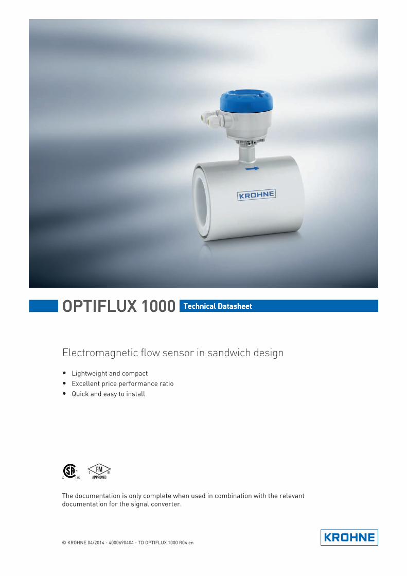
Electromagnetic flow sensor in sandwich design
• Lightweight and compact• Excellent price performance ratio• Quick and easy to install
© KROHNE 04/2014 - 4000690404 - TD OPTIFLUX 1000 R04 en
The documentation is only complete when used in combination with the relevant documentation for the signal converter.
CONTENTS
2 www.krohne.com 04/2014 - 4000690404 - TD OPTIFLUX 1000 R04 en
OPTIFLUX 1000
1 Product features 3
1.1 Cost efficient and reliable flow sensor ............................................................................ 31.2 Options.............................................................................................................................. 51.3 Measuring principle.......................................................................................................... 6
2 Technical data 7
2.1 Technical data................................................................................................................... 72.2 Measuring accuracy ....................................................................................................... 112.3 Dimensions and weights ................................................................................................ 12
3 Installation 14
3.1 Intended use ................................................................................................................... 143.2 General notes on installation ......................................................................................... 14
3.2.1 Vibration ................................................................................................................................ 143.2.2 Magnetic field........................................................................................................................ 14
3.3 Installation conditions .................................................................................................... 153.3.1 Inlet and outlet ...................................................................................................................... 153.3.2 Bends in 2 or 3 dimensions................................................................................................... 153.3.3 T-section ............................................................................................................................... 153.3.4 Bends .................................................................................................................................... 163.3.5 Open feed or discharge......................................................................................................... 163.3.6 Flange deviation .................................................................................................................... 173.3.7 Pump ..................................................................................................................................... 173.3.8 Control valve ......................................................................................................................... 173.3.9 Air venting and vacuum forces ............................................................................................. 183.3.10 Mounting position................................................................................................................ 18
4 Electrical connections 19
4.1 Safety instructions.......................................................................................................... 194.2 Grounding ....................................................................................................................... 194.3 Virtual reference for IFC 300 (C, W and F version) ........................................................ 20
5 Notes 21
PRODUCT FEATURES 1
3
OPTIFLUX 1000
www.krohne.com04/2014 - 4000690404 - TD OPTIFLUX 1000 R04 en
1.1 Cost efficient and reliable flow sensor
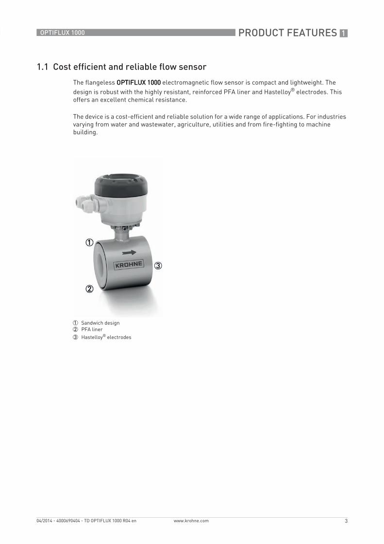
The flangeless OPTIFLUX 1000OPTIFLUX 1000OPTIFLUX 1000OPTIFLUX 1000 electromagnetic flow sensor is compact and lightweight. The design is robust with the highly resistant, reinforced PFA liner and Hastelloy® electrodes. This offers an excellent chemical resistance.
The device is a cost-efficient and reliable solution for a wide range of applications. For industries varying from water and wastewater, agriculture, utilities and from fire-fighting to machine building.
1 Sandwich design2 PFA liner
3 Hastelloy® electrodes
1 PRODUCT FEATURES
4
OPTIFLUX 1000
www.krohne.com 04/2014 - 4000690404 - TD OPTIFLUX 1000 R04 en
Highlights• Sandwich (wafer) design• Lightweight and compact for easy handling and space saving installation• Affordable price• Excellent chemical resistance• Bi-directional measurements• No pressure loss• Insensitive to vibrations• No internal moving parts, no maintenance
Industries• Machine building• Energy, HVAC• Water & wastewater• Agriculture• Process industries
Applications• Mixing, batching and dosing systems, filtration systems, pump control• Water flow monitoring• Water circulation and treatment systems• Fire-fighting systems, foam mixing, control of sprinkler systems• Heat transfer and cooling systems• Water including raw water, process water, wastewater, salt water, heated and cooled water • Mud, slurry, sludge, manure
PRODUCT FEATURES 1
5
OPTIFLUX 1000
www.krohne.com04/2014 - 4000690404 - TD OPTIFLUX 1000 R04 en
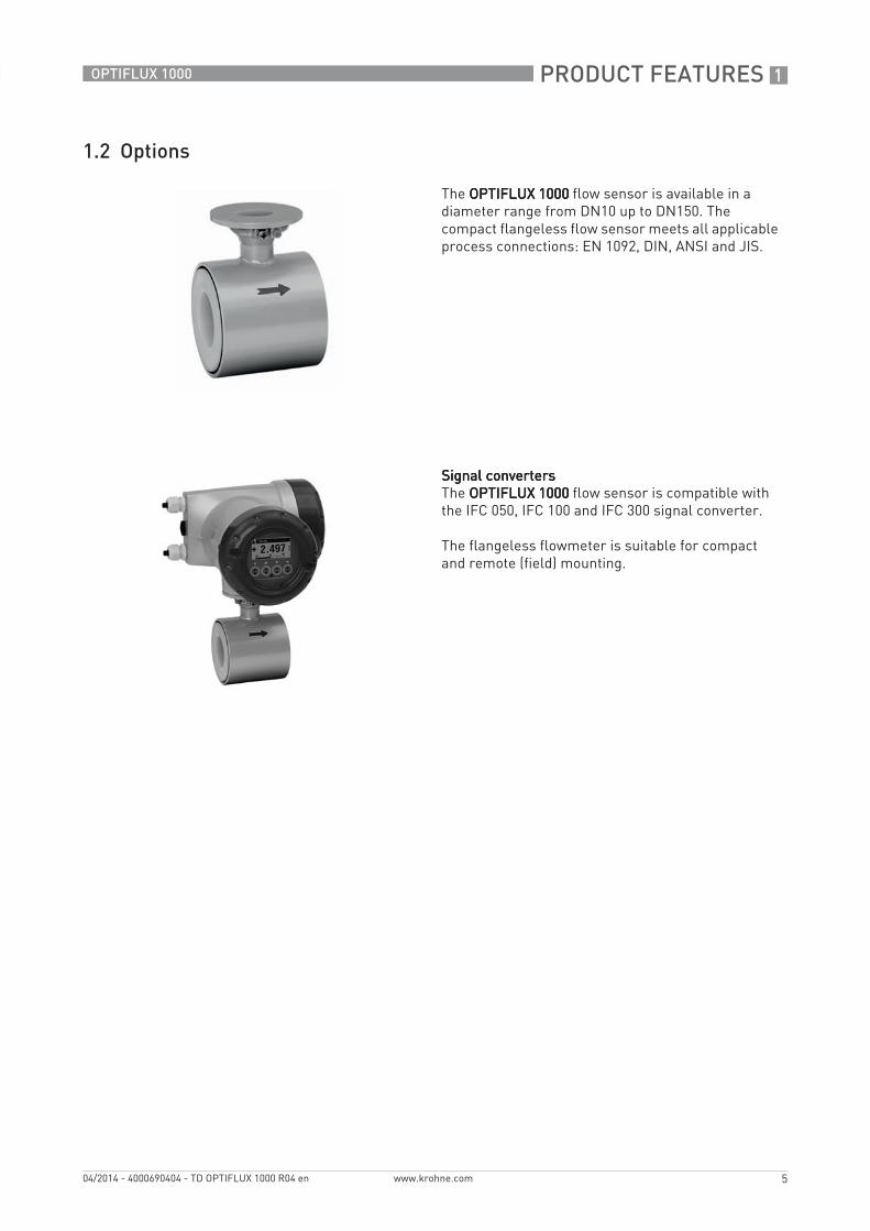
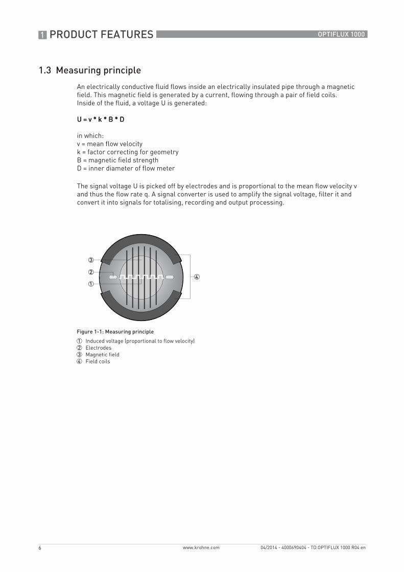
1.2 Options
The OPTIFLUX 1000OPTIFLUX 1000OPTIFLUX 1000OPTIFLUX 1000 flow sensor is available in a diameter range from DN10 up to DN150. The compact flangeless flow sensor meets all applicable process connections: EN 1092, DIN, ANSI and JIS.
Signal convertersSignal convertersSignal convertersSignal convertersThe OPTIFLUX 1000OPTIFLUX 1000OPTIFLUX 1000OPTIFLUX 1000 flow sensor is compatible with the IFC 050, IFC 100 and IFC 300 signal converter.
The flangeless flowmeter is suitable for compact and remote (field) mounting.
1 PRODUCT FEATURES
6
OPTIFLUX 1000
www.krohne.com 04/2014 - 4000690404 - TD OPTIFLUX 1000 R04 en
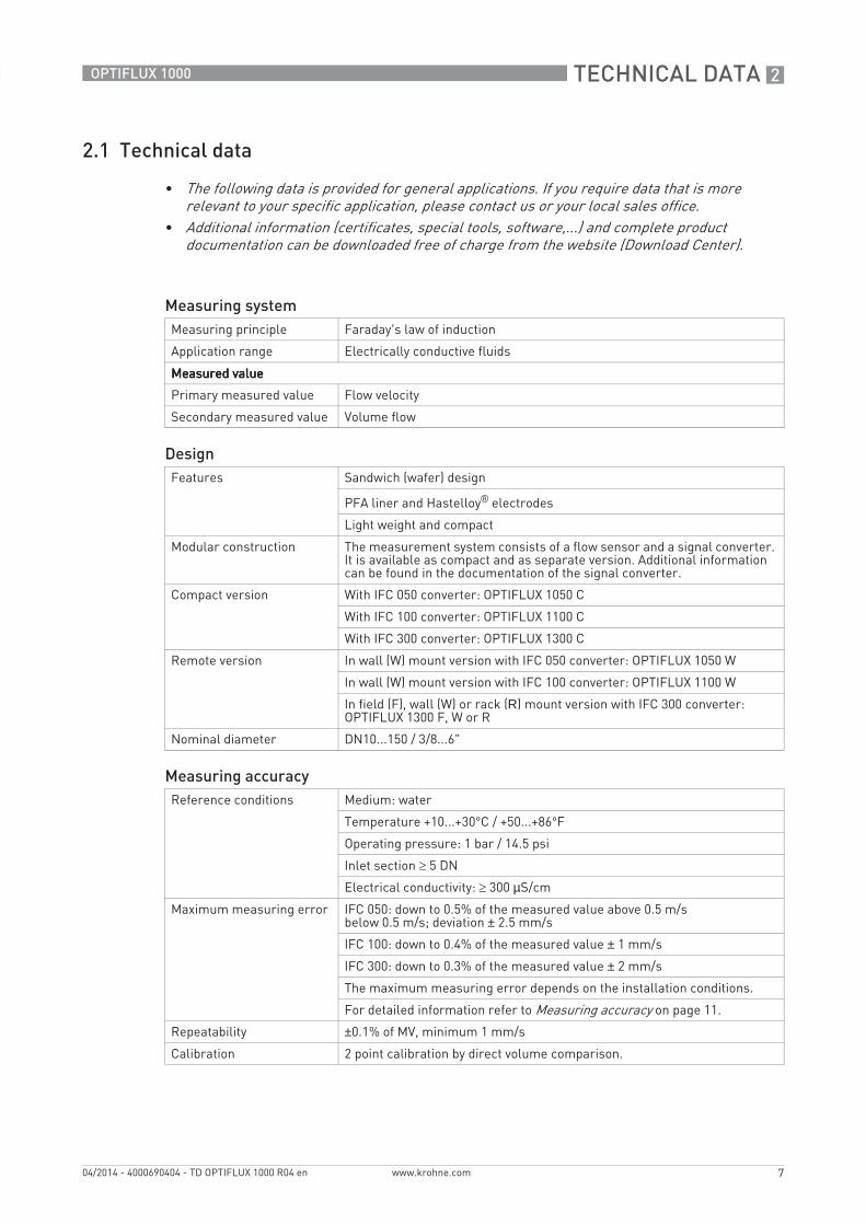
1.3 Measuring principle
An electrically conductive fluid flows inside an electrically insulated pipe through a magnetic field. This magnetic field is generated by a current, flowing through a pair of field coils.Inside of the fluid, a voltage U is generated:
U = v * k * B * DU = v * k * B * DU = v * k * B * DU = v * k * B * D
in which:v = mean flow velocityk = factor correcting for geometryB = magnetic field strengthD = inner diameter of flow meter
The signal voltage U is picked off by electrodes and is proportional to the mean flow velocity v and thus the flow rate q. A signal converter is used to amplify the signal voltage, filter it and convert it into signals for totalising, recording and output processing.
Figure 1-1: Measuring principle
1 Induced voltage (proportional to flow velocity)2 Electrodes3 Magnetic field4 Field coils
TECHNICAL DATA 2
7
OPTIFLUX 1000
www.krohne.com04/2014 - 4000690404 - TD OPTIFLUX 1000 R04 en
2.1 Technical data
• The following data is provided for general applications. If you require data that is more relevant to your specific application, please contact us or your local sales office.
• Additional information (certificates, special tools, software,...) and complete product documentation can be downloaded free of charge from the website (Download Center).
Measuring systemMeasuring principle Faraday's law of induction
Application range Electrically conductive fluids
Measured valueMeasured valueMeasured valueMeasured value
Primary measured value Flow velocity
Secondary measured value Volume flow
DesignFeatures Sandwich (wafer) design
PFA liner and Hastelloy® electrodes
Light weight and compact
Modular construction The measurement system consists of a flow sensor and a signal converter. It is available as compact and as separate version. Additional information can be found in the documentation of the signal converter.
Compact version With IFC 050 converter: OPTIFLUX 1050 C
With IFC 100 converter: OPTIFLUX 1100 C
With IFC 300 converter: OPTIFLUX 1300 C
Remote version In wall (W) mount version with IFC 050 converter: OPTIFLUX 1050 W
In wall (W) mount version with IFC 100 converter: OPTIFLUX 1100 W
In field (F), wall (W) or rack (R) mount version with IFC 300 converter: OPTIFLUX 1300 F, W or R
Nominal diameter DN10...150 / 3/8...6"
Measuring accuracyReference conditions Medium: water
Temperature +10...+30°C / +50...+86°F
Operating pressure: 1 bar / 14.5 psi
Inlet section ≥ 5 DN
Electrical conductivity: ≥ 300 µS/cm
Maximum measuring error IFC 050: down to 0.5% of the measured value above 0.5 m/sbelow 0.5 m/s; deviation ± 2.5 mm/s
IFC 100: down to 0.4% of the measured value ± 1 mm/s
IFC 300: down to 0.3% of the measured value ± 2 mm/s
The maximum measuring error depends on the installation conditions.
For detailed information refer to Measuring accuracy on page 11.
Repeatability ±0.1% of MV, minimum 1 mm/s
Calibration 2 point calibration by direct volume comparison.
2 TECHNICAL DATA
8
OPTIFLUX 1000
www.krohne.com 04/2014 - 4000690404 - TD OPTIFLUX 1000 R04 en
Operating conditionsTemperatureTemperatureTemperatureTemperature
Process temperature -25...+120°C / -13...+248°F
Ambient temperature -25…+65°C / -13…+149°F
Protect electronics against self-heating at ambient temperatures above -55°C / +131°F
Storage temperature -50…+70°C / -58…+158°F
Measurement rangeMeasurement rangeMeasurement rangeMeasurement range -12...+12 m/s / -40...+40 ft/s
PressurePressurePressurePressure
Ambient pressure Atmospheric
Operating pressure Up to 16 bar / 230 psi
Vacuum load 0 mbar / psi absolute
Pressure loss Negligible
Pressure ranges for secondary containment
Pressure resistant up to 40 bar / 580 psi
Burst pressure up to approx. 160 bar / 2320 psi
Chemical propertiesChemical propertiesChemical propertiesChemical properties
Physical condition Electrically conductive liquids
Electrical conductivity Standard: ≥ 5 μS/cm
Demineralized water: ≥ 20 μS/cm
Permissible gas content (volume)
IFC 050: ≤ 3%
IFC 100: ≤ 3%
IFC 300: ≤ 5%
Permissible solid content (volume)
IFC 050: ≤ 10%
IFC 100: ≤ 10%
IFC 300: ≤ 70%
Installation conditionsInstallation Assure that the flow sensor is always fully filled.
For detailed information refer to Installation on page 14
Flow direction Forward and reverse
Arrow on flow sensor indicates positive flow direction.
Inlet run ≥ 5 DN
Outlet run ≥ 2 DN
Dimensions and weights For detailed information refer to Dimensions and weights on page 12
TECHNICAL DATA 2
9
OPTIFLUX 1000
www.krohne.com04/2014 - 4000690404 - TD OPTIFLUX 1000 R04 en
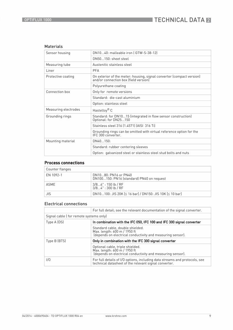
MaterialsSensor housing DN10...40: malleable iron ( GTW-S-38-12)
DN50...150: sheet steel
Measuring tube Austenitic stainless steel
Liner PFA
Protective coating On exterior of the meter: housing, signal converter (compact version) and/or connection box (field version)
Polyurethane coating
Connection box Only for remote versions
Standard: die-cast aluminium
Option: stainless steel
Measuring electrodes Hastelloy® C
Grounding rings Standard: for DN10...15 (integrated in flow sensor construction)Optional: for DN25...150
Stainless steel 316 (1.4571) (AISI 316 Ti)
Grounding rings can be omitted with virtual reference option for the IFC 300 converter.
Mounting material DN40...150:
Standard: rubber centering sleeves
Option: galvanized steel or stainless steel stud bolts and nuts
Process connectionsProcess connectionsProcess connectionsProcess connectionsCounter flanges
EN 1092-1 DN10...80: PN16 or PN40DN100...150: PN16 (standard) PN40 on request
ASME 3/8...6" : 150 lb / RF3/8...4" : 300 lb / RF
JIS DN10...100: JIS 20K [≤ 16 bar] / DN150: JIS 10K [≤ 10 bar]
Electrical connectionsFor full detail; see the relevant documentation of the signal converter.
Signal cable ( for remote systems only)
Type A (DS) In combination with the IFC 050, IFC 100 and IFC 300 signal converterIn combination with the IFC 050, IFC 100 and IFC 300 signal converterIn combination with the IFC 050, IFC 100 and IFC 300 signal converterIn combination with the IFC 050, IFC 100 and IFC 300 signal converter
Standard cable, double shielded.Max. length: 600 m / 1950 ft (depends on electrical conductivity and measuring sensor).
Type B (BTS) Only in combination with the IFC 300 signal converterOnly in combination with the IFC 300 signal converterOnly in combination with the IFC 300 signal converterOnly in combination with the IFC 300 signal converter
Optional cable, triple shielded.Max. length: 600 m / 1950 ft (depends on electrical conductivity and measuring sensor).
I/O For full details of I/O options, including data streams and protocols, see technical datasheet of the relevant signal converter.
2 TECHNICAL DATA
10
OPTIFLUX 1000
www.krohne.com 04/2014 - 4000690404 - TD OPTIFLUX 1000 R04 en
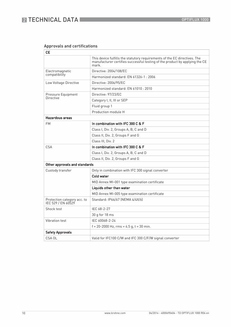
Approvals and certificationsCECECECE
This device fulfills the statutory requirements of the EC directives. The manufacturer certifies successful testing of the product by applying the CE mark.
Electromagnetic compatibility
Directive: 2004/108/EC
Harmonized standard: EN 61326-1 : 2006
Low Voltage Directive Directive: 2006/95/EC
Harmonized standard: EN 61010 : 2010
Pressure Equipment Directive
Directive: 97/23/EC
Category I, II, III or SEP
Fluid group 1
Production module H
Hazardous areasHazardous areasHazardous areasHazardous areas
FM In combination with IFC 300 C & FIn combination with IFC 300 C & FIn combination with IFC 300 C & FIn combination with IFC 300 C & F
Class I, Div. 2, Groups A, B, C and D
Class II, Div. 2, Groups F and G
Class III, Div. 2
CSA In combination with IFC 300 C & FIn combination with IFC 300 C & FIn combination with IFC 300 C & FIn combination with IFC 300 C & F
Class I, Div. 2, Groups A, B, C and D
Class II, Div. 2, Groups F and G
Other approvals and standardsOther approvals and standardsOther approvals and standardsOther approvals and standards
Custody transfer Only in combination with IFC 300 signal converter
Cold waterCold waterCold waterCold water
MID Annex MI-001 type examination certificate
Liquids other than waterLiquids other than waterLiquids other than waterLiquids other than water
MID Annex MI-005 type examination certificate
Protection category acc. toIEC 529 / EN 60529
Standard: IP66/67 (NEMA 4/4X/6)
Shock test IEC 68-2-27
30 g for 18 ms
Vibration test IEC 60068-2-24
f = 20-2000 Hz, rms = 4.5 g, t = 30 min.
Safety ApprovalsSafety ApprovalsSafety ApprovalsSafety Approvals
CSA OL Valid for IFC100 C/W and IFC 300 C/F/W signal converter
TECHNICAL DATA 2
11
OPTIFLUX 1000
www.krohne.com04/2014 - 4000690404 - TD OPTIFLUX 1000 R04 en
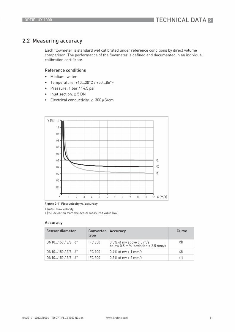
2.2 Measuring accuracy
Each flowmeter is standard wet calibrated under reference conditions by direct volume comparison. The performance of the flowmeter is defined and documented in an individual calibration certificate.
Reference conditions• Medium: water• Temperature: +10...30°C / +50...86°F• Pressure: 1 bar / 14.5 psi• Inlet section: ≥ 5 DN• Electrical conductivity: ≥ 300 μS/cm
Accuracy
Figure 2-1: Flow velocity vs. accuracy
X [m/s]: flow velocityY [%]: deviation from the actual measured value (mv)
Sensor diameter Converter type
Accuracy Curve
DN10...150 / 3/8...6" IFC 050 0.5% of mv above 0.5 m/sbelow 0.5 m/s, deviation ± 2.5 mm/s
3
DN10...150 / 3/8...6" IFC 100 0.4% of mv + 1 mm/s 2
DN10...150 / 3/8...6" IFC 300 0.3% of mv + 2 mm/s 1
2 TECHNICAL DATA
12
OPTIFLUX 1000
www.krohne.com 04/2014 - 4000690404 - TD OPTIFLUX 1000 R04 en
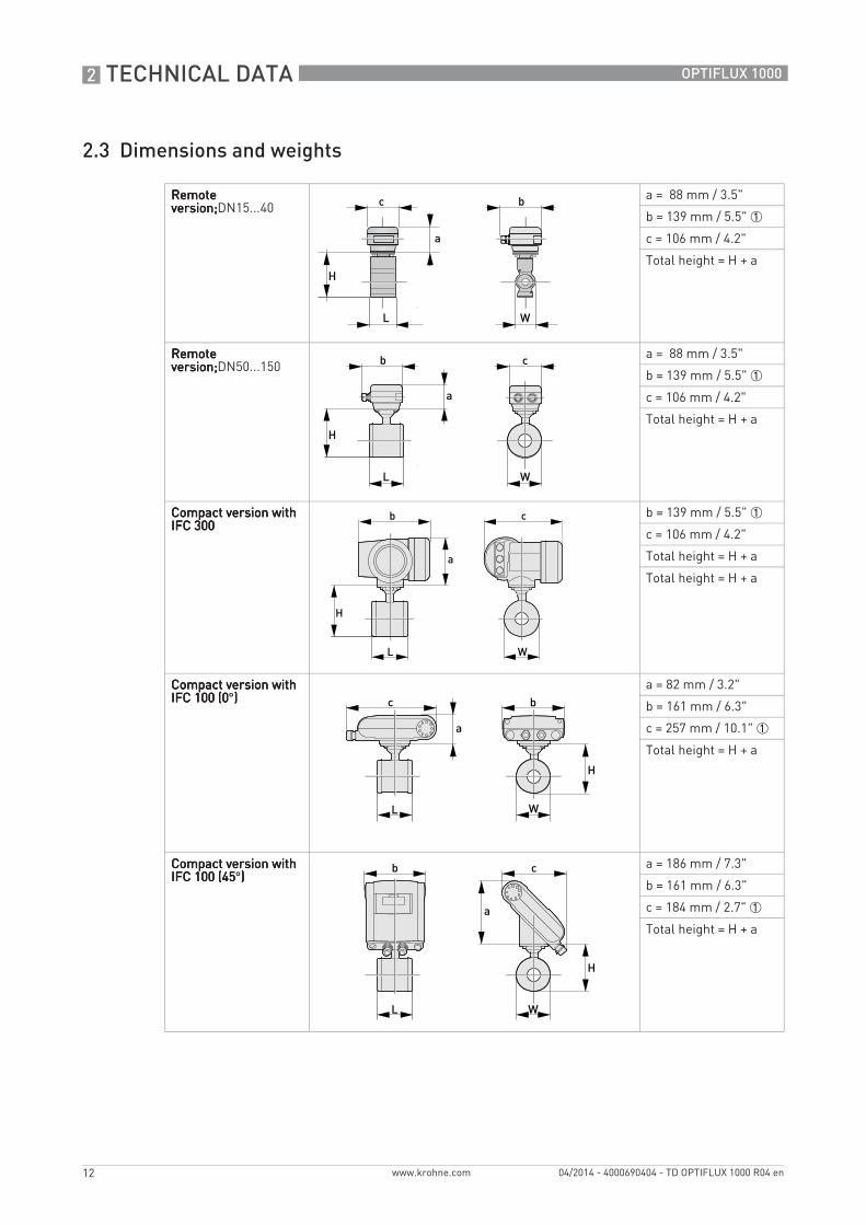
2.3 Dimensions and weights
Remote Remote Remote Remote version;version;version;version;DN15...40
a = 88 mm / 3.5"
b = 139 mm / 5.5" 1
c = 106 mm / 4.2"
Total height = H + a
Remote Remote Remote Remote version;version;version;version;DN50...150
a = 88 mm / 3.5"
b = 139 mm / 5.5" 1
c = 106 mm / 4.2"
Total height = H + a
Compact version with Compact version with Compact version with Compact version with IFC 300IFC 300IFC 300IFC 300
b = 139 mm / 5.5" 1
c = 106 mm / 4.2"
Total height = H + a
Total height = H + a
Compact version with Compact version with Compact version with Compact version with IFC 100 (0IFC 100 (0IFC 100 (0IFC 100 (0°))))
a = 82 mm / 3.2"
b = 161 mm / 6.3"
c = 257 mm / 10.1" 1
Total height = H + a
Compact version with Compact version with Compact version with Compact version with IFC 100 (45IFC 100 (45IFC 100 (45IFC 100 (45°))))
a = 186 mm / 7.3"
b = 161 mm / 6.3"
c = 184 mm / 2.7" 1
Total height = H + a
TECHNICAL DATA 2
13
OPTIFLUX 1000
www.krohne.com04/2014 - 4000690404 - TD OPTIFLUX 1000 R04 en
EN 1092-1
ASME B16.5
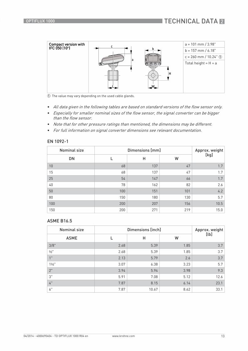
Compact version with Compact version with Compact version with Compact version with IFC 050 (10IFC 050 (10IFC 050 (10IFC 050 (10°))))
a = 101 mm / 3.98"
b = 157 mm / 6.18"
c = 260 mm / 10.24" 1
Total height = H + a
1 The value may vary depending on the used cable glands.
• All data given in the following tables are based on standard versions of the flow sensor only.• Especially for smaller nominal sizes of the flow sensor, the signal converter can be bigger
than the flow sensor.• Note that for other pressure ratings than mentioned, the dimensions may be different.• For full information on signal converter dimensions see relevant documentation.
Nominal size Dimensions [mm] Approx. weight [kg]
DN L H W
10 68 137 47 1.7
15 68 137 47 1.7
25 54 147 66 1.7
40 78 162 82 2.6
50 100 151 101 4.2
80 150 180 130 5.7
100 200 207 156 10.5
150 200 271 219 15.0
Nominal size Dimensions [inch] Approx. weight [lb]
ASME L H W
3/8" 2.68 5.39 1.85 3.7
½" 2.68 5.39 1.85 3.7
1" 2.13 5.79 2.6 3.7
1½" 3.07 6.38 3.23 5.7
2" 3.94 5.94 3.98 9.3
3" 5.91 7.08 5.12 12.6
4" 7.87 8.15 6.14 23.1
6" 7.87 10.67 8.62 33.1
3 INSTALLATION
14
OPTIFLUX 1000
www.krohne.com 04/2014 - 4000690404 - TD OPTIFLUX 1000 R04 en
3.1 Intended use
The electromagnetic flowmeter is designed exclusively to measure the flow of electrically conductive, liquid media.
3.2 General notes on installation
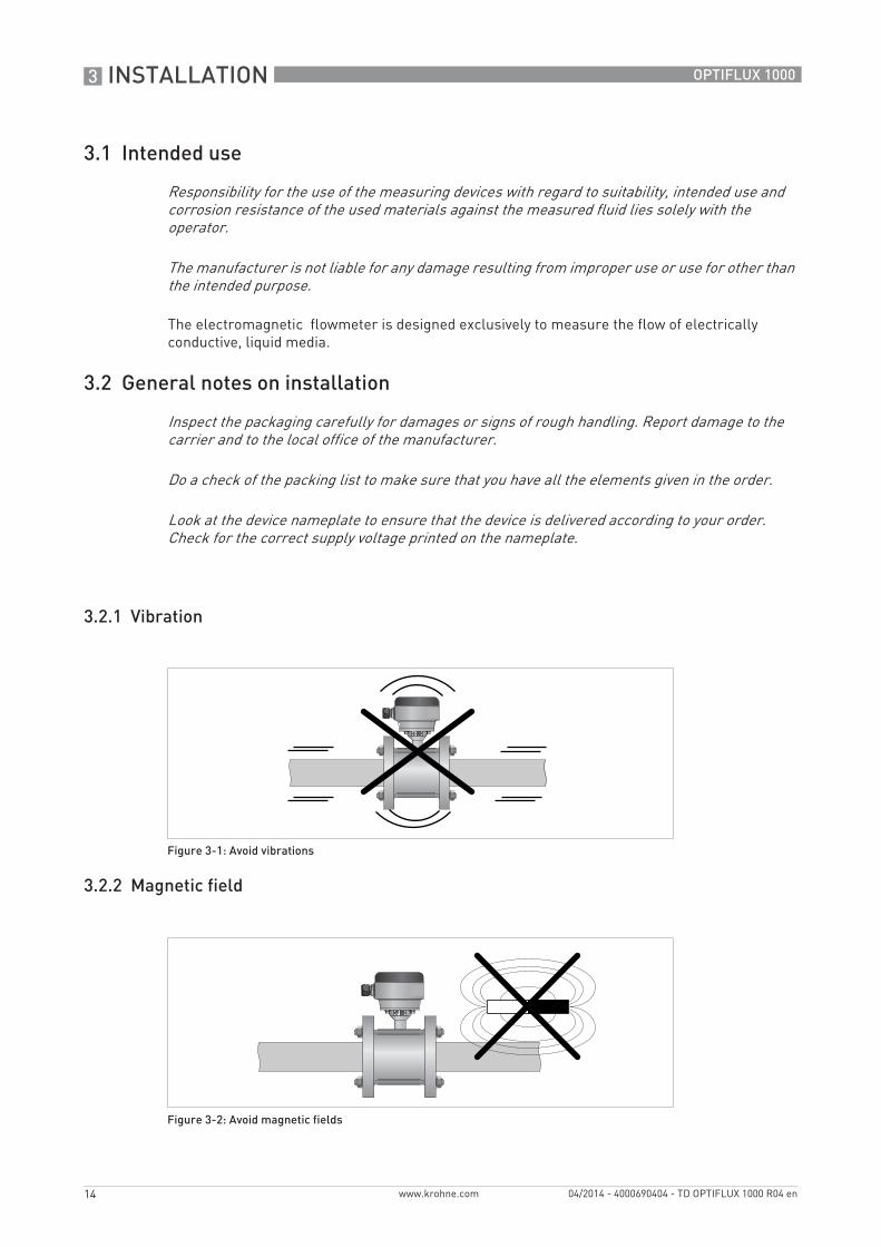
3.2.1 Vibration
3.2.2 Magnetic field
Responsibility for the use of the measuring devices with regard to suitability, intended use and corrosion resistance of the used materials against the measured fluid lies solely with the operator.
The manufacturer is not liable for any damage resulting from improper use or use for other than the intended purpose.
Inspect the packaging carefully for damages or signs of rough handling. Report damage to the carrier and to the local office of the manufacturer.
Do a check of the packing list to make sure that you have all the elements given in the order.
Look at the device nameplate to ensure that the device is delivered according to your order. Check for the correct supply voltage printed on the nameplate.
Figure 3-1: Avoid vibrations
Figure 3-2: Avoid magnetic fields
INSTALLATION 3
15
OPTIFLUX 1000
www.krohne.com04/2014 - 4000690404 - TD OPTIFLUX 1000 R04 en
3.3 Installation conditions
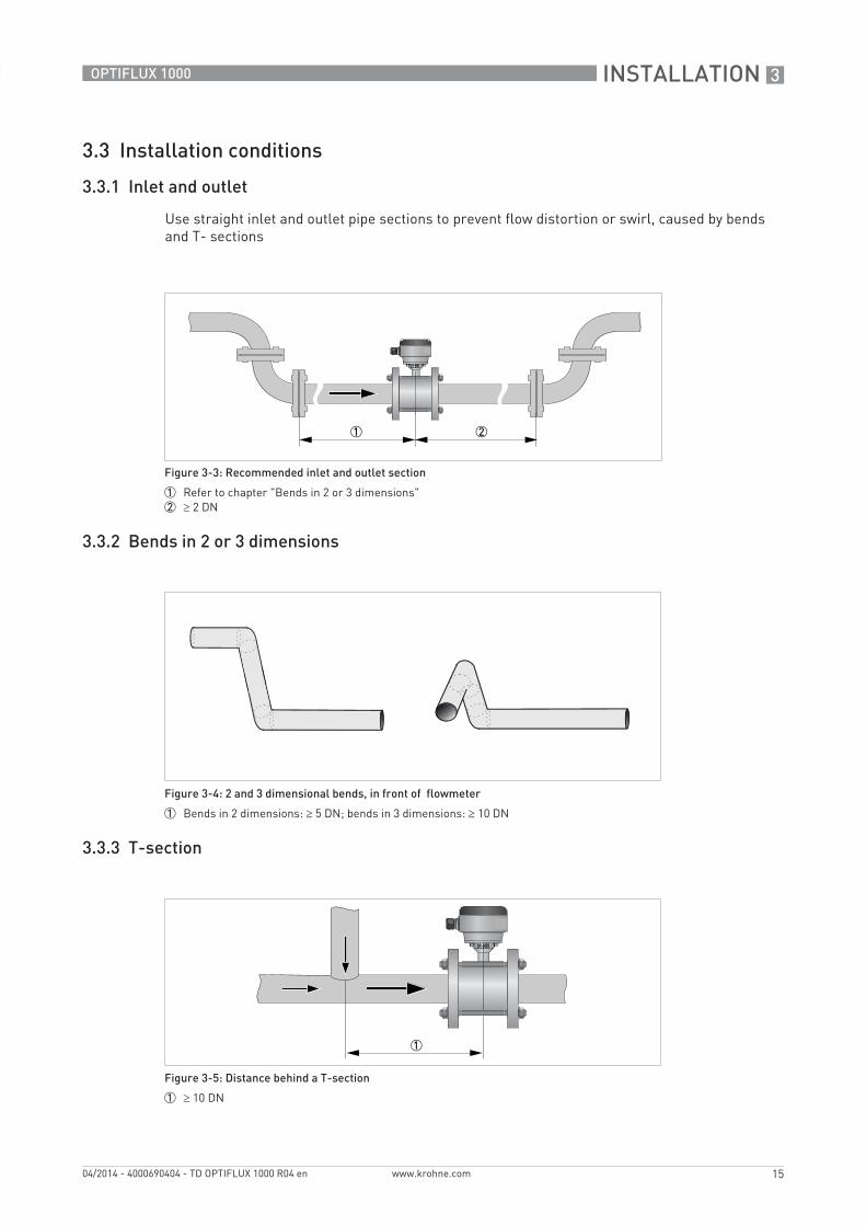
3.3.1 Inlet and outlet
Use straight inlet and outlet pipe sections to prevent flow distortion or swirl, caused by bends and T- sections
3.3.2 Bends in 2 or 3 dimensions
3.3.3 T-section
Figure 3-3: Recommended inlet and outlet section
1 Refer to chapter "Bends in 2 or 3 dimensions"2 ≥ 2 DN
Figure 3-4: 2 and 3 dimensional bends, in front of flowmeter
1 Bends in 2 dimensions: ≥ 5 DN; bends in 3 dimensions: ≥ 10 DN
Figure 3-5: Distance behind a T-section
1 ≥ 10 DN
3 INSTALLATION
16
OPTIFLUX 1000
www.krohne.com 04/2014 - 4000690404 - TD OPTIFLUX 1000 R04 en
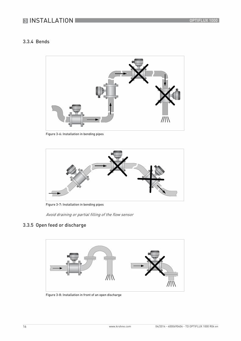
3.3.4 Bends
3.3.5 Open feed or discharge
Figure 3-6: Installation in bending pipes
Figure 3-7: Installation in bending pipes
Avoid draining or partial filling of the flow sensor
Figure 3-8: Installation in front of an open discharge
INSTALLATION 3
17
OPTIFLUX 1000
www.krohne.com04/2014 - 4000690404 - TD OPTIFLUX 1000 R04 en
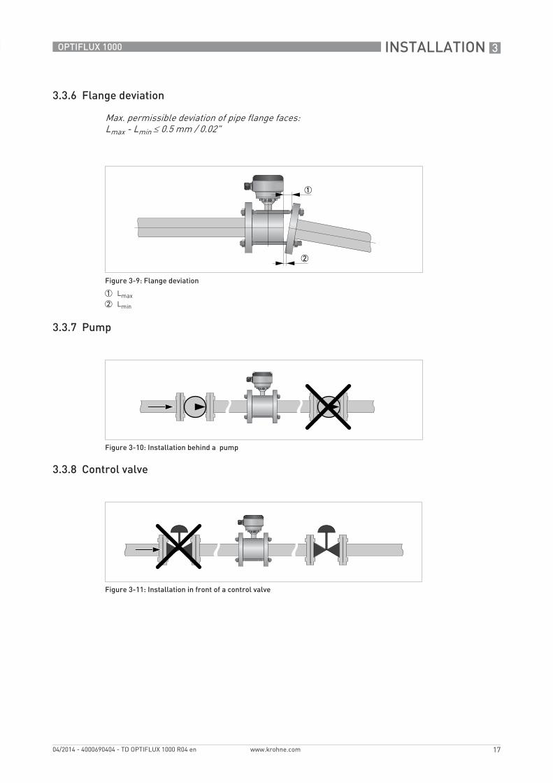
3.3.6 Flange deviation
3.3.7 Pump
3.3.8 Control valve
Max. permissible deviation of pipe flange faces: Lmax - Lmin ≤ 0.5 mm / 0.02"
Figure 3-9: Flange deviation
1 Lmax2 Lmin
Figure 3-10: Installation behind a pump
Figure 3-11: Installation in front of a control valve
3 INSTALLATION
18
OPTIFLUX 1000
www.krohne.com 04/2014 - 4000690404 - TD OPTIFLUX 1000 R04 en
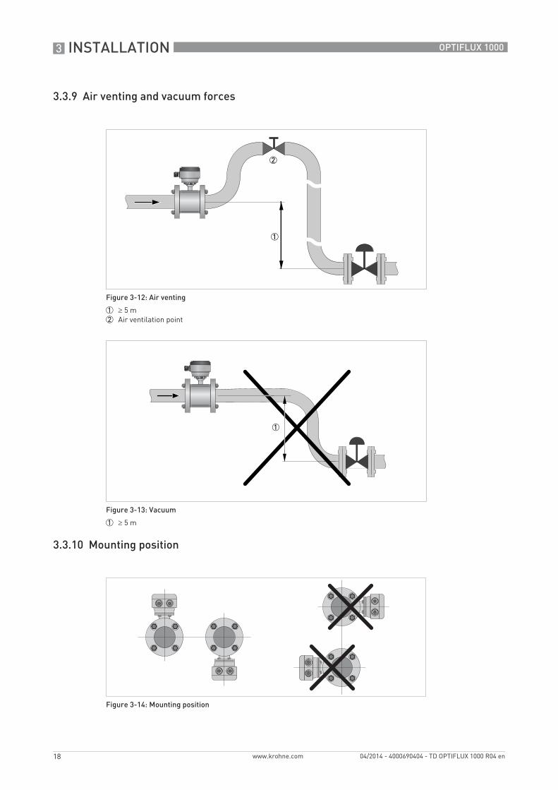
3.3.9 Air venting and vacuum forces
3.3.10 Mounting position
Figure 3-12: Air venting
1 ≥ 5 m2 Air ventilation point
Figure 3-13: Vacuum
1 ≥ 5 m
Figure 3-14: Mounting position
ELECTRICAL CONNECTIONS 4
19
OPTIFLUX 1000
www.krohne.com04/2014 - 4000690404 - TD OPTIFLUX 1000 R04 en
4.1 Safety instructions
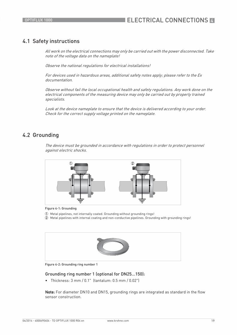
4.2 Grounding
Grounding ring number 1 (optional for DN25...150):• Thickness: 3 mm / 0.1" (tantalum: 0.5 mm / 0.02")
Note:Note:Note:Note: For diameter DN10 and DN15, grounding rings are integrated as standard in the flow sensor construction.
All work on the electrical connections may only be carried out with the power disconnected. Take note of the voltage data on the nameplate!
Observe the national regulations for electrical installations!
For devices used in hazardous areas, additional safety notes apply; please refer to the Ex documentation.
Observe without fail the local occupational health and safety regulations. Any work done on the electrical components of the measuring device may only be carried out by properly trained specialists.
Look at the device nameplate to ensure that the device is delivered according to your order. Check for the correct supply voltage printed on the nameplate.
The device must be grounded in accordance with regulations in order to protect personnel against electric shocks.
Figure 4-1: Grounding
1 Metal pipelines, not internally coated. Grounding without grounding rings!2 Metal pipelines with internal coating and non-conductive pipelines. Grounding with grounding rings!
Figure 4-2: Grounding ring number 1
4 ELECTRICAL CONNECTIONS
20
OPTIFLUX 1000
www.krohne.com 04/2014 - 4000690404 - TD OPTIFLUX 1000 R04 en
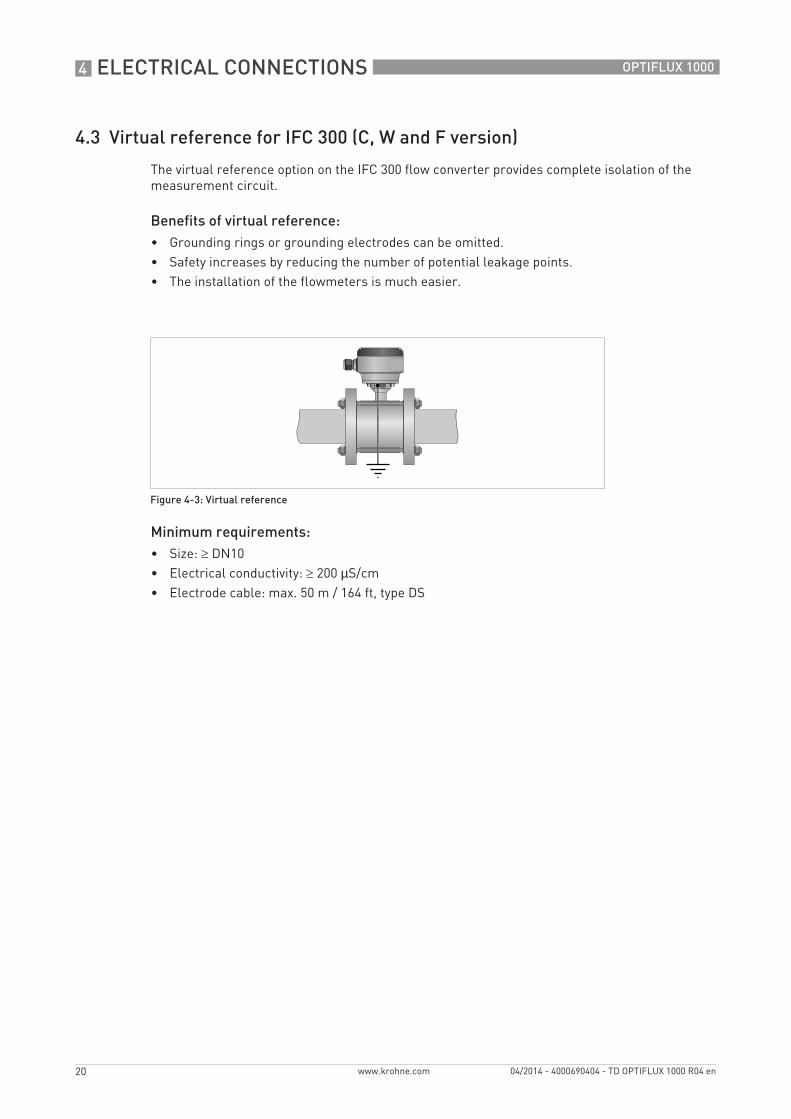
4.3 Virtual reference for IFC 300 (C, W and F version)
The virtual reference option on the IFC 300 flow converter provides complete isolation of the measurement circuit.
Benefits of virtual reference:• Grounding rings or grounding electrodes can be omitted.• Safety increases by reducing the number of potential leakage points.• The installation of the flowmeters is much easier.
Minimum requirements:• Size: ≥ DN10• Electrical conductivity: ≥ 200 µS/cm• Electrode cable: max. 50 m / 164 ft, type DS
Figure 4-3: Virtual reference
NOTES 5
21
OPTIFLUX 1000
www.krohne.com04/2014 - 4000690404 - TD OPTIFLUX 1000 R04 en
5 NOTES
22
OPTIFLUX 1000
www.krohne.com 04/2014 - 4000690404 - TD OPTIFLUX 1000 R04 en

NOTES 5
23
OPTIFLUX 1000
www.krohne.com04/2014 - 4000690404 - TD OPTIFLUX 1000 R04 en

KROHNE product overview
• Electromagnetic flowmeters
• Variable area flowmeters
• Ultrasonic flowmeters
• Mass flowmeters
• Vortex flowmeters
• Flow controllers
• Level meters
• Temperature assemblies
• Pressure transmitters
• Analysis products
• Products and systems for the oil & gas industry
• Measuring systems for the marine industry
Head Office KROHNE Messtechnik GmbHLudwig-Krohne-Str. 547058 Duisburg (Germany)Tel.:+49 203 301 0Fax:+49 203 301 103 89 [email protected]
© K
RO
HN
E 04
/201
4 -
4000
6904
04 -
TD
OP
TIFL
UX
1000
R04
en
- Su
bjec
t to
chan
ge w
ithou
t not
ice.
The current list of all KROHNE contacts and addresses can be found at:www.krohne.com