optiflux 4000 - process-instrumentation.net 4000.pdf · 2 07/2010 - 4000525102 - td optiflux 4000...
TRANSCRIPT
OPTIFLUX 4000OPTIFLUX 4000OPTIFLUX 4000OPTIFLUX 4000 Technical DatasheetTechnical DatasheetTechnical DatasheetTechnical Datasheet
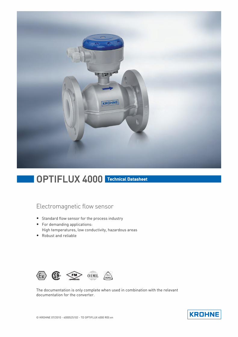
Electromagnetic flow sensor
• Standard flow sensor for the process industry• For demanding applications:
High temperatures, low conductivity, hazardous areas• Robust and reliable
© KROHNE 07/2010 - 4000525102 - TD OPTIFLUX 4000 R05 en
The documentation is only complete when used in combination with the relevant documentation for the converter.
CONTENTS
2 www.krohne.com 07/2010 - 4000525102 - TD OPTIFLUX 4000 R05 en
OPTIFLUX 4000
1 Product features 3
1.1 Standard solution for the process industry ..................................................................... 31.2 Options.............................................................................................................................. 51.3 Measuring principle.......................................................................................................... 7
2 Technical data 8
2.1 Technical data................................................................................................................... 82.2 Vacuum load ................................................................................................................... 142.3 MI-001............................................................................................................................. 152.4 MI-005............................................................................................................................. 162.5 OIML R49......................................................................................................................... 172.6 OIML R117....................................................................................................................... 182.7 Dimensions and weights ................................................................................................ 19
3 Installation 23
3.1 Intended use ................................................................................................................... 233.2 Installation conditions .................................................................................................... 23
3.2.1 Inlet and outlet ...................................................................................................................... 233.2.2 Mounting position.................................................................................................................. 233.2.3 Flange deviation .................................................................................................................... 243.2.4 T-section ............................................................................................................................... 243.2.5 Vibration ................................................................................................................................ 243.2.6 Magnetic field........................................................................................................................ 253.2.7 Bends .................................................................................................................................... 253.2.8 Open discharge ..................................................................................................................... 263.2.9 Control valve ......................................................................................................................... 263.2.10 Air venting ........................................................................................................................... 263.2.11 Pump ................................................................................................................................... 27
4 Electrical connections 28
4.1 Safety instructions.......................................................................................................... 284.2 Grounding ....................................................................................................................... 284.3 Virtual reference for IFC 300 (C, W and F version) ........................................................ 30
5 Notes 31
PRODUCT FEATURES 1
3
OPTIFLUX 4000
www.krohne.com07/2010 - 4000525102 - TD OPTIFLUX 4000 R05 en
1.1 Standard solution for the process industry
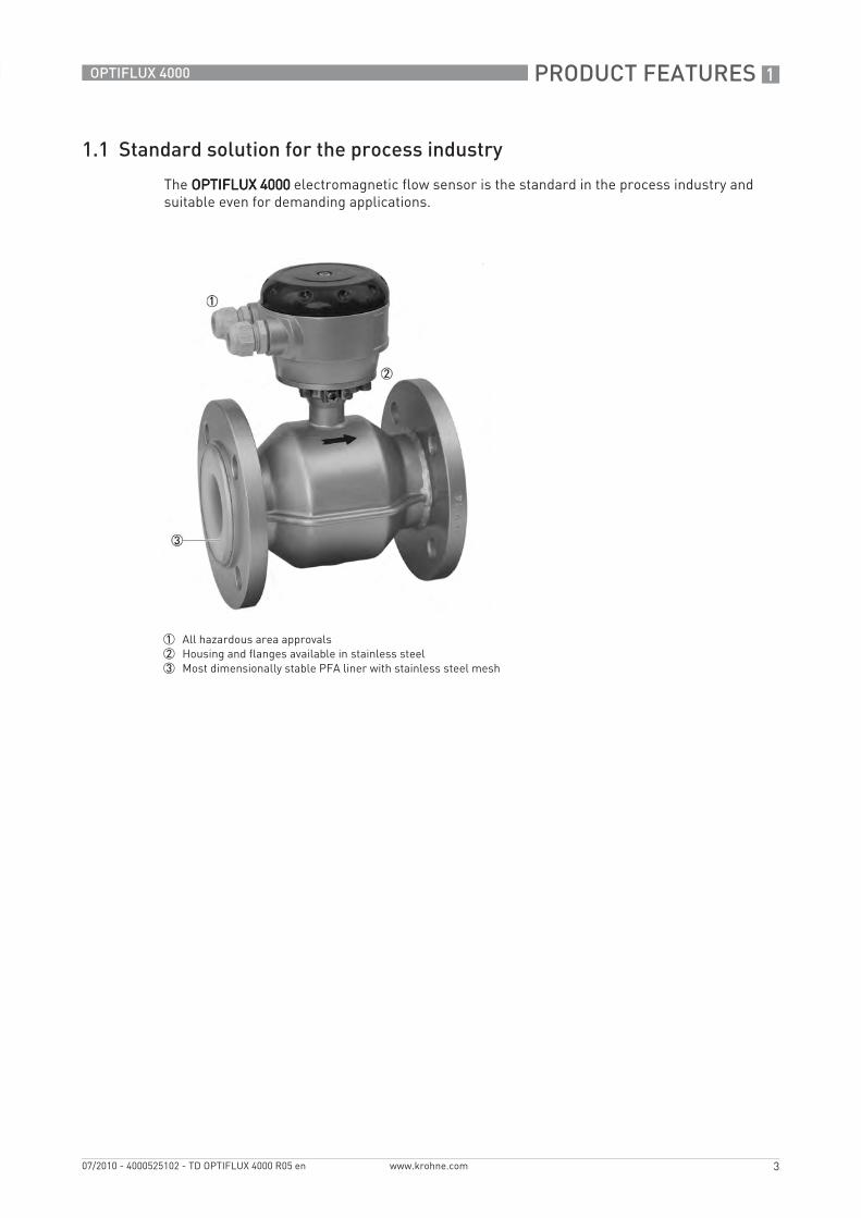
The OPTIFLUX 4000OPTIFLUX 4000OPTIFLUX 4000OPTIFLUX 4000 electromagnetic flow sensor is the standard in the process industry and suitable even for demanding applications.
1 All hazardous area approvals2 Housing and flanges available in stainless steel3 Most dimensionally stable PFA liner with stainless steel mesh
1 PRODUCT FEATURES
4
OPTIFLUX 4000
www.krohne.com 07/2010 - 4000525102 - TD OPTIFLUX 4000 R05 en
Highlights• Standard device in the process industry• Robust and reliable• More than 300,000 units operating in the field• Works reliably under demanding conditions: High temperatures (up to 180°C / 356°F) and low
conductivity (non-water from 1 µS/cm, water from 20 µS/cm)• Quick and easy to install and operate• Chemically resistant to alkaline solutions and acids
Industries• Chemicals• Pulp & Paper• Water• Wastewater• Minerals & Mining• Iron, Steel & Metals• Pharmaceuticals• Oil & gas
Applications• For clean liquids • For slurries and pastes with high solids content• For abrasive and aggressive products
PRODUCT FEATURES 1
5
OPTIFLUX 4000
www.krohne.com07/2010 - 4000525102 - TD OPTIFLUX 4000 R05 en
1.2 Options
The solution for any industry
Communication
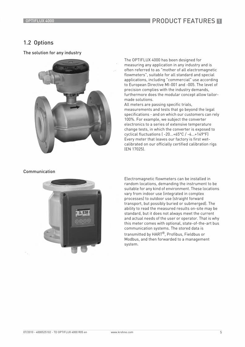
The OPTIFLUX 4000 has been designed for measuring any application in any industry and is often referred to as "mother of all electromagnetic flowmeters", suitable for all standard and special applications, including "commercial" use according to European Directive MI-001 and -005. The level of precision complies with the industry demands, furthermore does the modular concept allow tailor-made solutions.All meters are passing specific trials, measurements and tests that go beyond the legal specifications - and on which our customers can rely 100%. For example, we subject the converter electronics to a series of extensive temperature change tests, in which the converter is exposed to cyclical fluctuations ( -20...+65°C / -4...+149°F)Every meter that leaves our factory is first wet-calibrated on our officially certified calibration rigs (EN 17025).
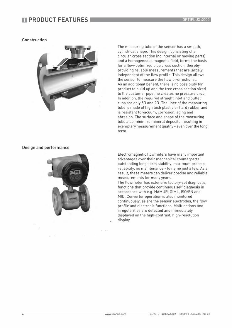
Electromagnetic flowmeters can be installed in random locations, demanding the instrument to be suitable for any kind of environment. These locations vary from indoor use (integrated in complex processes) to outdoor use (straight forward transport, but possibly buried or submerged). The ability to read the measured results on-site may be standard, but it does not always meet the current and actual needs of the user or operator. That is why this meter comes with optional, state-of-the-art bus communication systems. The stored data is transmitted by HART®, Profibus, Fieldbus or Modbus, and then forwarded to a management system.
1 PRODUCT FEATURES
6
OPTIFLUX 4000
www.krohne.com 07/2010 - 4000525102 - TD OPTIFLUX 4000 R05 en
Construction
Design and performance
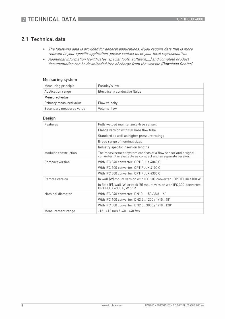
The measuring tube of the sensor has a smooth, cylindrical shape. This design, consisting of a circular cross section (no internal or moving parts) and a homogeneous magnetic field, forms the basis for a flow-optimized pipe cross section, thereby providing reliable measurements that are largely independent of the flow profile. This design allows the sensor to measure the flow bi-directional.As an additional benefit, there is no possibility for product to build up and the free cross section sized to the customer pipeline creates no pressure drop. In addition, the required straight inlet and outlet runs are only 5D and 2D. The liner of the measuring tube is made of high tech plastic or hard rubber and is resistant to vacuum, corrosion, aging and abrasion. The surface and shape of the measuring tube also minimize mineral deposits, resulting in exemplary measurement quality - even over the long term.
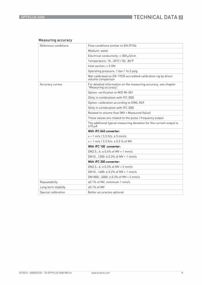
Electromagnetic flowmeters have many important advantages over their mechanical counterparts: outstanding long-term stability, maximum process reliability, no maintenance - to name just a few. As a result, these meters can deliver precise and reliable measurements for many years.The flowmeter has extensive factory-set diagnostic functions that provide continuous self diagnosis in accordance with e.g. NAMUR, OIML, ISO/EN and MID. Converter operation is also monitored continuously, as are the sensor electrodes, the flow profile and electronic functions. Malfunctions and irregularities are detected and immediately displayed on the high-contrast, high-resolution display.

PRODUCT FEATURES 1
7
OPTIFLUX 4000
www.krohne.com07/2010 - 4000525102 - TD OPTIFLUX 4000 R05 en
1.3 Measuring principle
An electrically conductive fluid flows inside an electrically insulating pipe through a magnetic field. This magnetic field is generated by a current, flowing through a pair of field coils. Inside of the fluid, a voltage U is generated:U = v * k * B * DU = v * k * B * DU = v * k * B * DU = v * k * B * D
in which:v = mean flow velocityk = factor correcting for geometryB = magnetic field strengthD = inner diameter of flow meter
The signal voltage U is picked off by electrodes and is proportional to the mean flow velocity v and thus the flow rate q. A signal converter is used to amplify the signal voltage, filter it and convert it into signals for totalising, recording and output processing.
1 Induced voltage (proportional to flow velocity)2 Electrodes3 Magnetic field4 Field coils
2 TECHNICAL DATA
8
OPTIFLUX 4000
www.krohne.com 07/2010 - 4000525102 - TD OPTIFLUX 4000 R05 en
2.1 Technical data
• The following data is provided for general applications. If you require data that is more relevant to your specific application, please contact us or your local representative.
• Additional information (certificates, special tools, software,...) and complete product documentation can be downloaded free of charge from the website (Download Center).
Measuring systemMeasuring principle Faraday's law
Application range Electrically conductive fluids
Measured valueMeasured valueMeasured valueMeasured value
Primary measured value Flow velocity
Secondary measured value Volume flow
DesignFeatures Fully welded maintenance-free sensor.
Flange version with full bore flow tube
Standard as well as higher pressure ratings
Broad range of nominal sizes
Industry specific insertion lengths
Modular construction The measurement system consists of a flow sensor and a signal converter. It is available as compact and as separate version.
Compact version With IFC 040 converter: OPTIFLUX 4040 C
With IFC 100 converter: OPTIFLUX 4100 C
With IFC 300 converter: OPTIFLUX 4300 C
Remote version In wall (W) mount version with IFC 100 converter : OPTIFLUX 4100 W
In field (F), wall (W) or rack (R) mount version with IFC 300 converter: OPTIFLUX 4300 F, W or R
Nominal diameter With IFC 040 converter: DN10... 150 / 3/8... 6"
With IFC 100 converter: DN2.5...1200 / 1/10...48"
With IFC 300 converter: DN2.5...3000 / 1/10...120"
Measurement range -12...+12 m/s / -40...+40 ft/s
TECHNICAL DATA 2
9
OPTIFLUX 4000
www.krohne.com07/2010 - 4000525102 - TD OPTIFLUX 4000 R05 en
Measuring accuracyReference conditions Flow conditions similar to EN 29104
Medium: water
Electrical conductivity: ≥ 300 μS/cm
Temperature: 10...30°C / 50...86°F
Inlet section: ≥ 5 DN
Operating pressure: 1 bar / 14.5 psig
Wet calibrated on EN 17025 accredited calibration rig by direct volume comparison
Accuracy curves For detailed information on the measuring accuracy, see chapter "Measuring accuracy".
Option: verification to MID MI-001
(Only in combination with IFC 300)
Option: calibration according to OIML R49
(Only in combination with IFC 300)
Related to volume flow (MV = Measured Value)
These values are related to the pulse / frequency output
The additional typical measuring deviation for the current output is ±10 μA
With IFC 040 converter:With IFC 040 converter:With IFC 040 converter:With IFC 040 converter:
v < 1 m/s / 3.3 ft/s: ± 5 mm/s
v > 1 m/s / 3.3 ft/s: ± 0.5 % of MV
With IFC 100 converter:With IFC 100 converter:With IFC 100 converter:With IFC 100 converter:
DN2.5...6: ± 0.4% of MV + 1 mm/s
DN10...1200: ± 0.3% of MV + 1 mm/s
With IFC 300 converter:With IFC 300 converter:With IFC 300 converter:With IFC 300 converter:
DN2.5...6: ± 0.3% of MV + 2 mm/s
DN10...1600: ± 0.2% of MV + 1 mm/s
DN1800...3000: ± 0.3% of MV + 2 mm/s
Repeatability ±0.1% of MV, minimum 1 mm/s
Long term stability ±0.1% of MV
Special calibration Better accuracies optional
2 TECHNICAL DATA
10
OPTIFLUX 4000
www.krohne.com 07/2010 - 4000525102 - TD OPTIFLUX 4000 R05 en
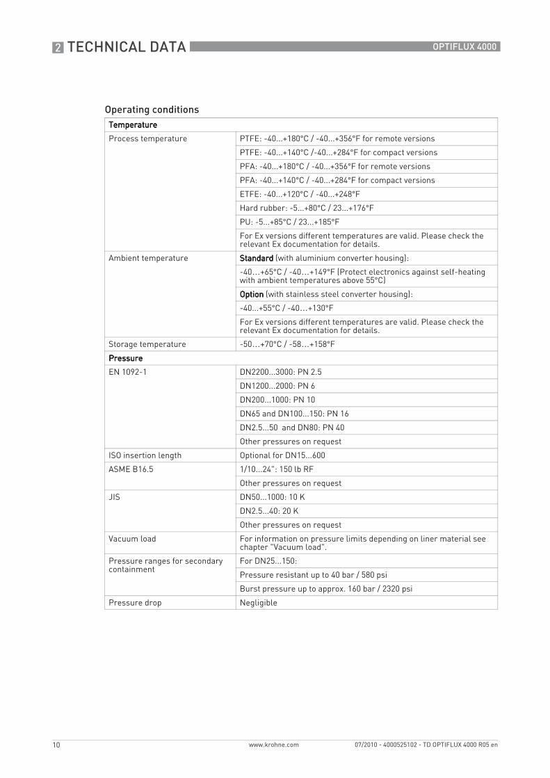
Operating conditionsTemperatureTemperatureTemperatureTemperature
Process temperature PTFE: -40...+180°C / -40...+356°F for remote versions
PTFE: -40...+140°C /-40...+284°F for compact versions
PFA: -40...+180°C / -40...+356°F for remote versions
PFA: -40...+140°C / -40...+284°F for compact versions
ETFE: -40...+120°C / -40...+248°F
Hard rubber: -5...+80°C / 23...+176°F
PU: -5...+85°C / 23...+185°F
For Ex versions different temperatures are valid. Please check the relevant Ex documentation for details.
Ambient temperature StandardStandardStandardStandard (with aluminium converter housing):
-40…+65°C / -40…+149°F (Protect electronics against self-heating with ambient temperatures above 55°C)
OptionOptionOptionOption (with stainless steel converter housing):
-40...+55°C / -40…+130°F
For Ex versions different temperatures are valid. Please check the relevant Ex documentation for details.
Storage temperature -50…+70°C / -58…+158°F
PressurePressurePressurePressure
EN 1092-1 DN2200...3000: PN 2.5
DN1200...2000: PN 6
DN200...1000: PN 10
DN65 and DN100...150: PN 16
DN2.5...50 and DN80: PN 40
Other pressures on request
ISO insertion length Optional for DN15...600
ASME B16.5 1/10...24": 150 lb RF
Other pressures on request
JIS DN50...1000: 10 K
DN2.5...40: 20 K
Other pressures on request
Vacuum load For information on pressure limits depending on liner material see chapter "Vacuum load".
Pressure ranges for secondary containment
For DN25...150:
Pressure resistant up to 40 bar / 580 psi
Burst pressure up to approx. 160 bar / 2320 psi
Pressure drop Negligible
TECHNICAL DATA 2
11
OPTIFLUX 4000
www.krohne.com07/2010 - 4000525102 - TD OPTIFLUX 4000 R05 en
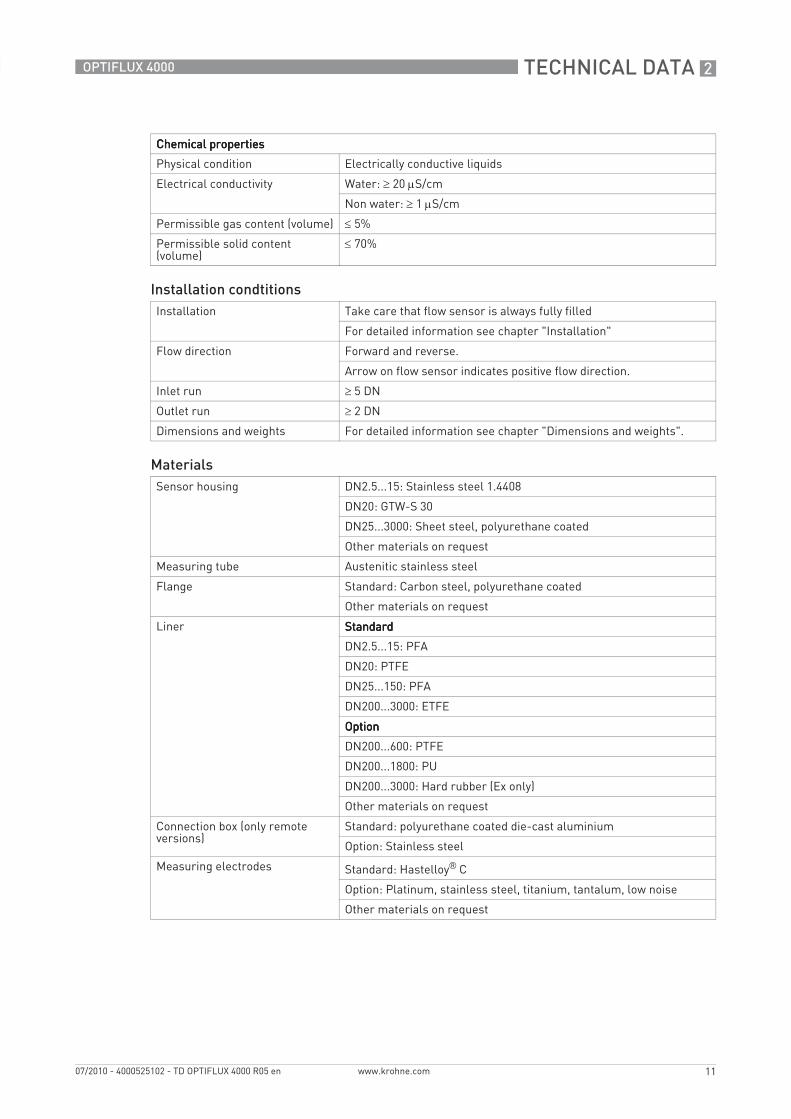
Chemical propertiesChemical propertiesChemical propertiesChemical properties
Physical condition Electrically conductive liquids
Electrical conductivity Water: ≥ 20 μS/cm
Non water: ≥ 1 μS/cm
Permissible gas content (volume) ≤ 5%
Permissible solid content (volume)
≤ 70%
Installation condtitionsInstallation Take care that flow sensor is always fully filled
For detailed information see chapter "Installation"
Flow direction Forward and reverse.
Arrow on flow sensor indicates positive flow direction.
Inlet run ≥ 5 DN
Outlet run ≥ 2 DN
Dimensions and weights For detailed information see chapter "Dimensions and weights".
MaterialsSensor housing DN2.5...15: Stainless steel 1.4408
DN20: GTW-S 30
DN25...3000: Sheet steel, polyurethane coated
Other materials on request
Measuring tube Austenitic stainless steel
Flange Standard: Carbon steel, polyurethane coated
Other materials on request
Liner StandardStandardStandardStandard
DN2.5...15: PFA
DN20: PTFE
DN25...150: PFA
DN200...3000: ETFE
OptionOptionOptionOption
DN200...600: PTFE
DN200...1800: PU
DN200...3000: Hard rubber (Ex only)
Other materials on request
Connection box (only remote versions)
Standard: polyurethane coated die-cast aluminium
Option: Stainless steel
Measuring electrodes Standard: Hastelloy® C
Option: Platinum, stainless steel, titanium, tantalum, low noise
Other materials on request
2 TECHNICAL DATA
12
OPTIFLUX 4000
www.krohne.com 07/2010 - 4000525102 - TD OPTIFLUX 4000 R05 en
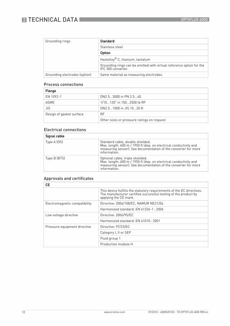
Grounding rings StandardStandardStandardStandard
Stainless steel
OptionOptionOptionOption
Hastelloy® C, titanium, tantalum
Grounding rings can be omitted with virtual reference option for the IFC 300 converter.
Grounding electrodes (option) Same material as measuring electrodes.
Process connectionsFlangeFlangeFlangeFlange
EN 1092-1 DN2.5...3000 in PN 2.5...40
ASME 1/10...120" in 150...2500 lb RF
JIS DN2.5...1000 in JIS 10...20 K
Design of gasket surface RF
Other sizes or pressure ratings on request
Electrical connectionsSignal cableSignal cableSignal cableSignal cable
Type A (DS) Standard cable, double shielded.Max. length: 600 m / 1950 ft (dep. on electrical conductivity and measuring sensor). See documentation of the converter for more information.
Type B (BTS) Optional cable, triple shielded.Max. length: 600 m / 1950 ft (dep. on electrical conductivity and measuring sensor). See documentation of the converter for more information.
Approvals and certificatesCECECECE
This device fulfills the statutory requirements of the EC directives. The manufacturer certifies successful testing of the product by applying the CE mark.
Electromagnetic compatibility Directive: 2004/108/EC, NAMUR NE21/04
Harmonized standard: EN 61326-1 : 2006
Low voltage directive Directive: 2006/95/EC
Harmonized standard: EN 61010 : 2001
Pressure equipment directive Directive: 97/23/EC
Category I, II or SEP
Fluid group 1
Production module H
TECHNICAL DATA 2
13
OPTIFLUX 4000
www.krohne.com07/2010 - 4000525102 - TD OPTIFLUX 4000 R05 en
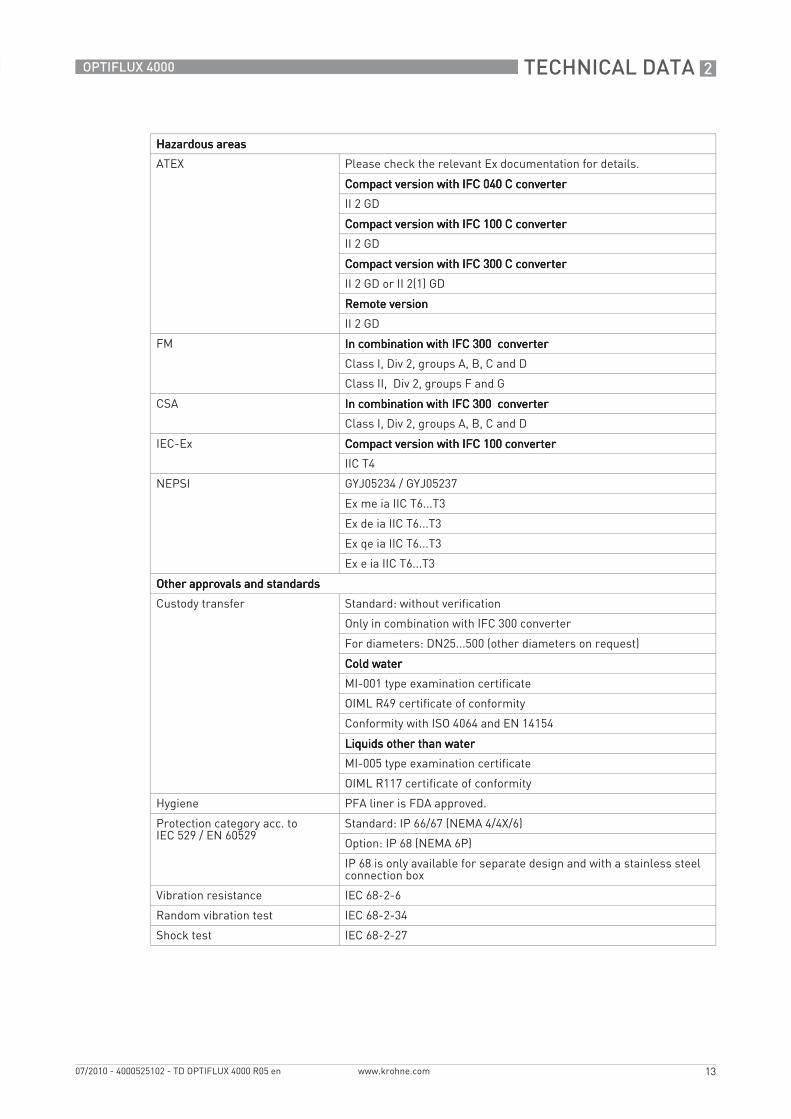
Hazardous areasHazardous areasHazardous areasHazardous areas
ATEX Please check the relevant Ex documentation for details.
Compact version with IFC 040 C converterCompact version with IFC 040 C converterCompact version with IFC 040 C converterCompact version with IFC 040 C converter
II 2 GD
Compact version with IFC 100 C converterCompact version with IFC 100 C converterCompact version with IFC 100 C converterCompact version with IFC 100 C converter
II 2 GD
Compact version with IFC 300 C converterCompact version with IFC 300 C converterCompact version with IFC 300 C converterCompact version with IFC 300 C converter
II 2 GD or II 2(1) GD
Remote versionRemote versionRemote versionRemote version
II 2 GD
FM In combination with IFC 300 converterIn combination with IFC 300 converterIn combination with IFC 300 converterIn combination with IFC 300 converter
Class I, Div 2, groups A, B, C and D
Class II, Div 2, groups F and G
CSA In combination with IFC 300 converterIn combination with IFC 300 converterIn combination with IFC 300 converterIn combination with IFC 300 converter
Class I, Div 2, groups A, B, C and D
IEC-Ex Compact version with IFC 100 converterCompact version with IFC 100 converterCompact version with IFC 100 converterCompact version with IFC 100 converter
IIC T4
NEPSI GYJ05234 / GYJ05237
Ex me ia IIC T6...T3
Ex de ia IIC T6...T3
Ex qe ia IIC T6...T3
Ex e ia IIC T6...T3
Other approvals and standardsOther approvals and standardsOther approvals and standardsOther approvals and standards
Custody transfer Standard: without verification
Only in combination with IFC 300 converter
For diameters: DN25...500 (other diameters on request)
Cold waterCold waterCold waterCold water
MI-001 type examination certificate
OIML R49 certificate of conformity
Conformity with ISO 4064 and EN 14154
Liquids other than waterLiquids other than waterLiquids other than waterLiquids other than water
MI-005 type examination certificate
OIML R117 certificate of conformity
Hygiene PFA liner is FDA approved.
Protection category acc. to IEC 529 / EN 60529
Standard: IP 66/67 (NEMA 4/4X/6)
Option: IP 68 (NEMA 6P)
IP 68 is only available for separate design and with a stainless steel connection box
Vibration resistance IEC 68-2-6
Random vibration test IEC 68-2-34
Shock test IEC 68-2-27
2 TECHNICAL DATA
14
OPTIFLUX 4000
www.krohne.com 07/2010 - 4000525102 - TD OPTIFLUX 4000 R05 en
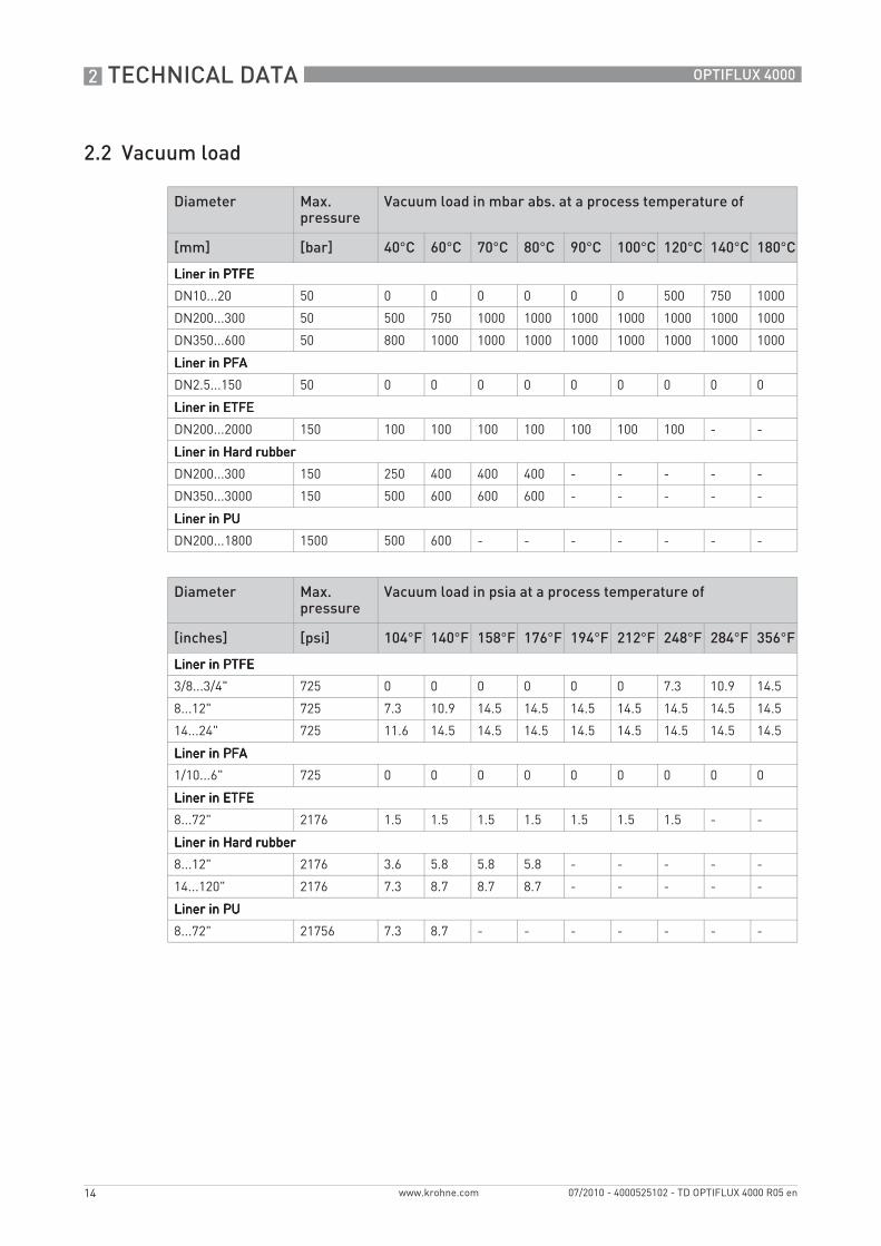
2.2 Vacuum load
Diameter Max. pressure
Vacuum load in mbar abs. at a process temperature of
[mm] [bar] 40°C 60°C 70°C 80°C 90°C 100°C 120°C 140°C 180°C
Liner in PTFELiner in PTFELiner in PTFELiner in PTFE
DN10...20 50 0 0 0 0 0 0 500 750 1000
DN200...300 50 500 750 1000 1000 1000 1000 1000 1000 1000
DN350...600 50 800 1000 1000 1000 1000 1000 1000 1000 1000
Liner in PFALiner in PFALiner in PFALiner in PFA
DN2.5...150 50 0 0 0 0 0 0 0 0 0
Liner in ETFELiner in ETFELiner in ETFELiner in ETFE
DN200...2000 150 100 100 100 100 100 100 100 - -
Liner in Hard rubberLiner in Hard rubberLiner in Hard rubberLiner in Hard rubber
DN200...300 150 250 400 400 400 - - - - -
DN350...3000 150 500 600 600 600 - - - - -
Liner in PULiner in PULiner in PULiner in PU
DN200...1800 1500 500 600 - - - - - - -
Diameter Max. pressure
Vacuum load in psia at a process temperature of
[inches] [psi] 104°F 140°F 158°F 176°F 194°F 212°F 248°F 284°F 356°F
Liner in PTFELiner in PTFELiner in PTFELiner in PTFE
3/8...3/4" 725 0 0 0 0 0 0 7.3 10.9 14.5
8...12" 725 7.3 10.9 14.5 14.5 14.5 14.5 14.5 14.5 14.5
14...24" 725 11.6 14.5 14.5 14.5 14.5 14.5 14.5 14.5 14.5
Liner in PFALiner in PFALiner in PFALiner in PFA
1/10...6" 725 0 0 0 0 0 0 0 0 0
Liner in ETFELiner in ETFELiner in ETFELiner in ETFE
8...72" 2176 1.5 1.5 1.5 1.5 1.5 1.5 1.5 - -
Liner in Hard rubberLiner in Hard rubberLiner in Hard rubberLiner in Hard rubber
8...12" 2176 3.6 5.8 5.8 5.8 - - - - -
14...120" 2176 7.3 8.7 8.7 8.7 - - - - -
Liner in PULiner in PULiner in PULiner in PU
8...72" 21756 7.3 8.7 - - - - - - -
TECHNICAL DATA 2
15
OPTIFLUX 4000
www.krohne.com07/2010 - 4000525102 - TD OPTIFLUX 4000 R05 en
2.3 MI-001
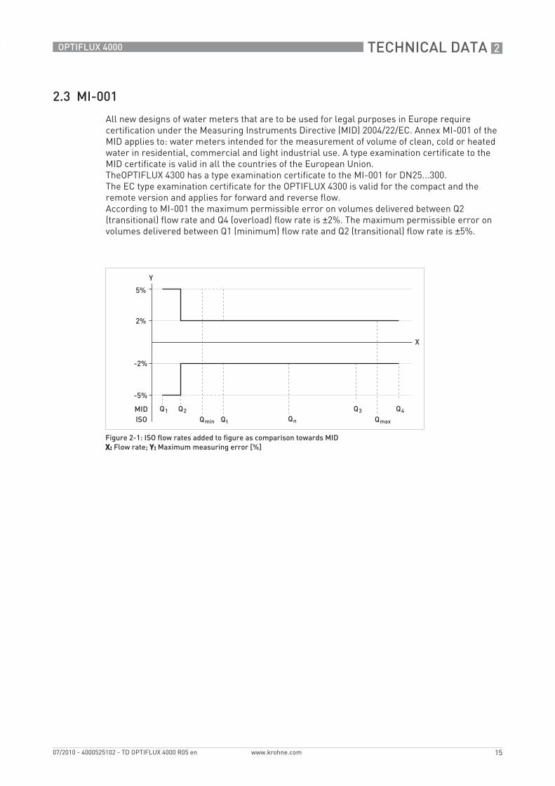
All new designs of water meters that are to be used for legal purposes in Europe require certification under the Measuring Instruments Directive (MID) 2004/22/EC. Annex MI-001 of the MID applies to: water meters intended for the measurement of volume of clean, cold or heated water in residential, commercial and light industrial use. A type examination certificate to the MID certificate is valid in all the countries of the European Union.TheOPTIFLUX 4300 has a type examination certificate to the MI-001 for DN25...300.The EC type examination certificate for the OPTIFLUX 4300 is valid for the compact and the remote version and applies for forward and reverse flow.According to MI-001 the maximum permissible error on volumes delivered between Q2 (transitional) flow rate and Q4 (overload) flow rate is ±2%. The maximum permissible error on volumes delivered between Q1 (minimum) flow rate and Q2 (transitional) flow rate is ±5%.
Figure 2-1: ISO flow rates added to figure as comparison towards MIDX:X:X:X: Flow rate; Y:Y:Y:Y: Maximum measuring error [%]

2 TECHNICAL DATA
16
OPTIFLUX 4000
www.krohne.com 07/2010 - 4000525102 - TD OPTIFLUX 4000 R05 en
2.4 MI-005
MI-005
DN Span (R) Flow rate [m3/h]
minimum Q1
Transitional Q2
Permanent Q3
Overload Q4
15 20 0.27 0.432 5.4 6.8
25 20 1.00 1.600 20.0 25.0
32 20 1.60 2.504 31.3 39.1
40 20 1.60 2.504 31.3 39.1
50 20 2.50 4.000 50.0 62.5
65 20 6.30 10.000 125.0 156.3
80 20 10.00 16.000 200.0 250.0
100 20 15.60 25.000 312.5 390.6
125 20 25.00 40.000 500.0 625.0
150 20 25.00 40.000 500.0 625.0
200 20 62.50 100.000 1250.0 1562.5
250 20 100.00 160.000 2000.0 2500.0
300 20 156.00 250.000 3125.0 3906.3
350 20 156.00 250.000 3125.0 3906.3
400 20 250.00 400.000 5000.0 6250.0
450 20 250.00 400.000 5000.0 6250.0
500 10 787.50 1260.000 7875.0 9843.8

TECHNICAL DATA 2
17
OPTIFLUX 4000
www.krohne.com07/2010 - 4000525102 - TD OPTIFLUX 4000 R05 en
2.5 OIML R49
The OIML R49 recommendation (2006) concerns water meters intended for the metering of cold potable water and hot water. The OPTIFLUX 4300 has a certificate of compliance with OIML R49, issued by NMi.The OIML R49 recommendation sets out the conditions to which water meters shall comply to meet the requirements of the services of legal metrology in countries where these instruments are subject to state controls.The measuring range of the water meter is determined by Q3 (nominal flow rate) and "R" (ratio).The OPTIFLUX 4300 meets the requirements for water meters of accuracy class 1 and 2.For accuracy class 1, the maximum permissible error for water meters is ±1% for the upper flow rate zone and ±3% for the lower flow rate zones.For accuracy class 2, the maximum permissible error for water meters is ±2% for the upper flow rate zone and ±5% for the lower flow rate zones.
Q1 = Q3 / RQ2 = Q1 * 1.6Q3 = Q1 * RQ4 = Q3 * 1.25
Figure 2-2: ISO flow rates added to figure as comparison towards OIMLX:X:X:X: Flow rate; Y:Y:Y:Y: Maximum measuring error [%]
1 ±3% for class 1, ±5% for class 2 devices2 ±1% for class 1, ±2% for class 2 devices
2 TECHNICAL DATA
18
OPTIFLUX 4000
www.krohne.com 07/2010 - 4000525102 - TD OPTIFLUX 4000 R05 en
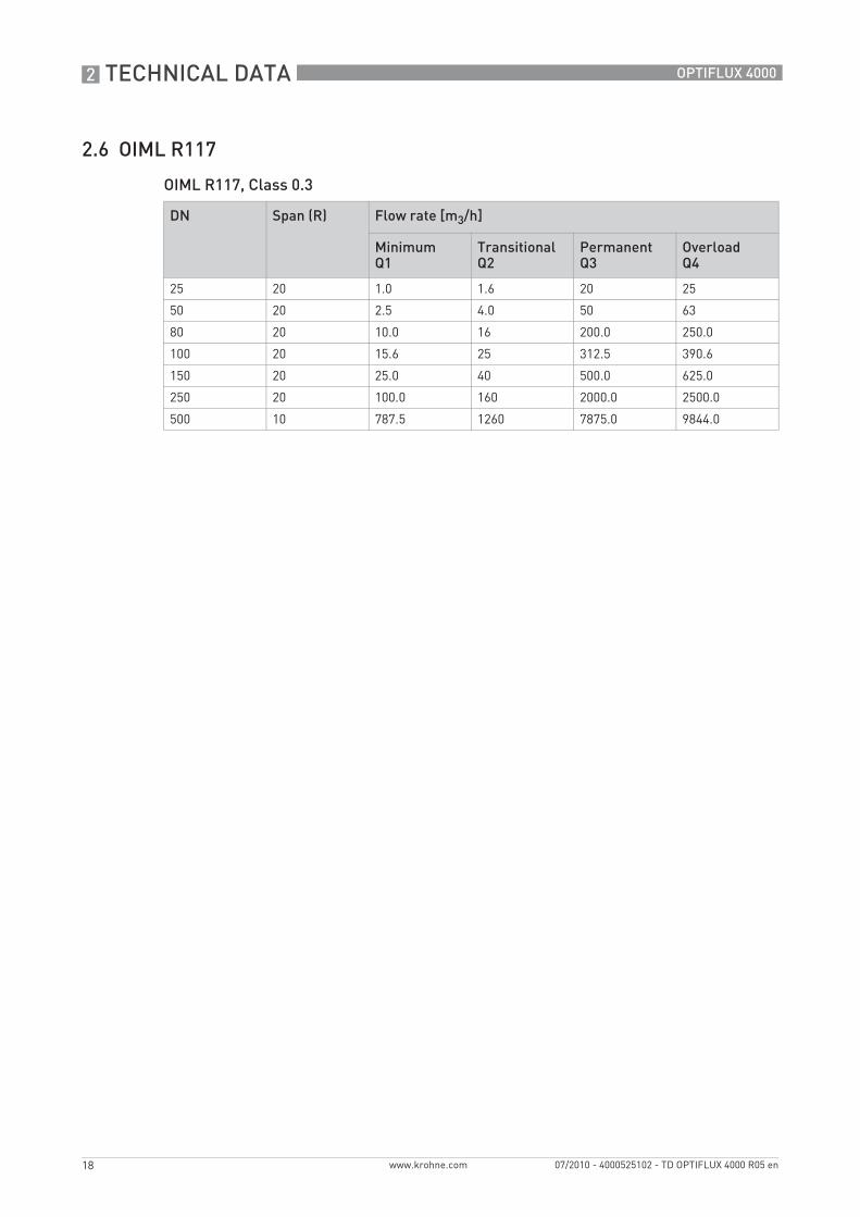
2.6 OIML R117
OIML R117, Class 0.3
DN Span (R) Flow rate [m3/h]
Minimum Q1
Transitional Q2
Permanent Q3
Overload Q4
25 20 1.0 1.6 20 25
50 20 2.5 4.0 50 63
80 20 10.0 16 200.0 250.0
100 20 15.6 25 312.5 390.6
150 20 25.0 40 500.0 625.0
250 20 100.0 160 2000.0 2500.0
500 10 787.5 1260 7875.0 9844.0
TECHNICAL DATA 2
19
OPTIFLUX 4000
www.krohne.com07/2010 - 4000525102 - TD OPTIFLUX 4000 R05 en
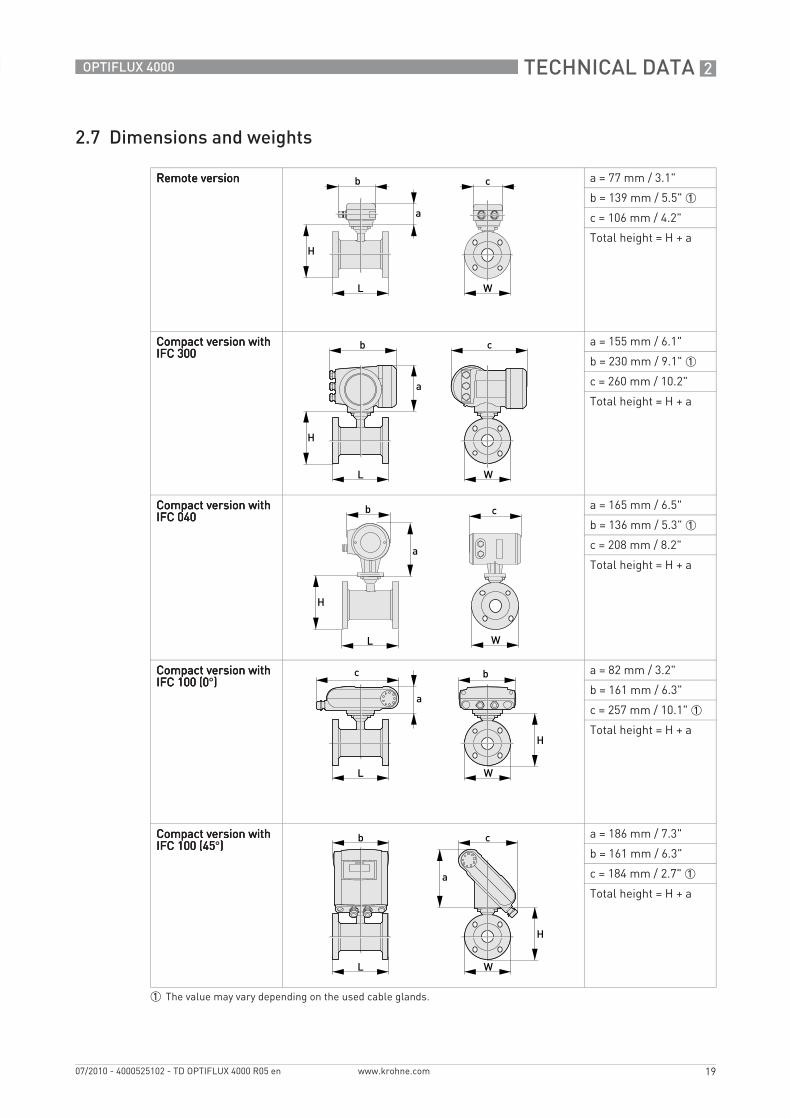
2.7 Dimensions and weights
Remote versionRemote versionRemote versionRemote version a = 77 mm / 3.1"
b = 139 mm / 5.5" 1
c = 106 mm / 4.2"
Total height = H + a
Compact version with Compact version with Compact version with Compact version with IFC 300IFC 300IFC 300IFC 300
a = 155 mm / 6.1"
b = 230 mm / 9.1" 1
c = 260 mm / 10.2"
Total height = H + a
Compact version with Compact version with Compact version with Compact version with IFC 040IFC 040IFC 040IFC 040
a = 165 mm / 6.5"
b = 136 mm / 5.3" 1
c = 208 mm / 8.2"
Total height = H + a
Compact version with Compact version with Compact version with Compact version with IFC 100 (0IFC 100 (0IFC 100 (0IFC 100 (0°))))
a = 82 mm / 3.2"
b = 161 mm / 6.3"
c = 257 mm / 10.1" 1
Total height = H + a
Compact version with Compact version with Compact version with Compact version with IFC 100 (45IFC 100 (45IFC 100 (45IFC 100 (45°))))
a = 186 mm / 7.3"
b = 161 mm / 6.3"
c = 184 mm / 2.7" 1
Total height = H + a
1 The value may vary depending on the used cable glands.
2 TECHNICAL DATA
20
OPTIFLUX 4000
www.krohne.com 07/2010 - 4000525102 - TD OPTIFLUX 4000 R05 en
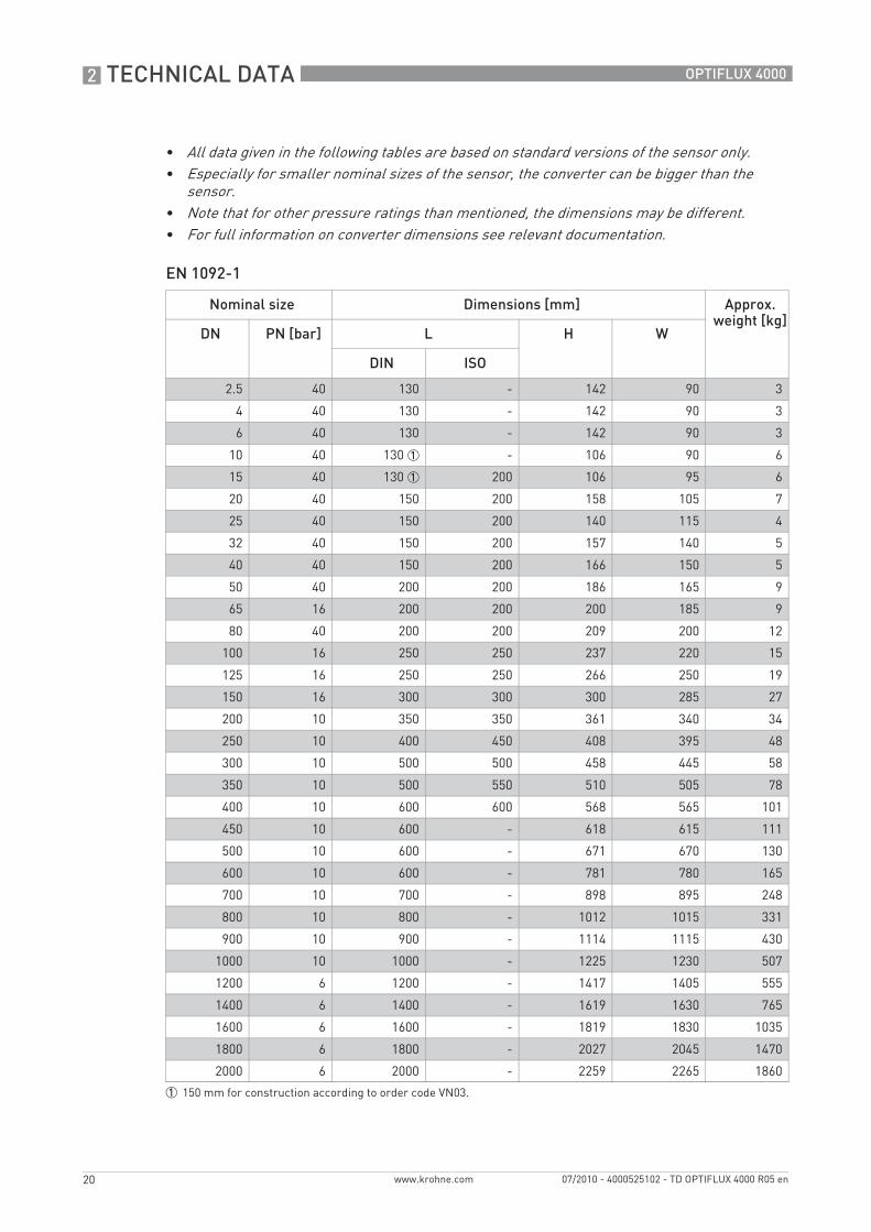
EN 1092-1
• All data given in the following tables are based on standard versions of the sensor only.• Especially for smaller nominal sizes of the sensor, the converter can be bigger than the
sensor.• Note that for other pressure ratings than mentioned, the dimensions may be different.• For full information on converter dimensions see relevant documentation.
Nominal size Dimensions [mm] Approx. weight [kg]
DN PN [bar] L H W
DIN ISO
2.5 40 130 - 142 90 3
4 40 130 - 142 90 3
6 40 130 - 142 90 3
10 40 130 1 - 106 90 6
15 40 130 1 200 106 95 6
20 40 150 200 158 105 7
25 40 150 200 140 115 4
32 40 150 200 157 140 5
40 40 150 200 166 150 5
50 40 200 200 186 165 9
65 16 200 200 200 185 9
80 40 200 200 209 200 12
100 16 250 250 237 220 15
125 16 250 250 266 250 19
150 16 300 300 300 285 27
200 10 350 350 361 340 34
250 10 400 450 408 395 48
300 10 500 500 458 445 58
350 10 500 550 510 505 78
400 10 600 600 568 565 101
450 10 600 - 618 615 111
500 10 600 - 671 670 130
600 10 600 - 781 780 165
700 10 700 - 898 895 248
800 10 800 - 1012 1015 331
900 10 900 - 1114 1115 430
1000 10 1000 - 1225 1230 507
1200 6 1200 - 1417 1405 555
1400 6 1400 - 1619 1630 765
1600 6 1600 - 1819 1830 1035
1800 6 1800 - 2027 2045 1470
2000 6 2000 - 2259 2265 1860
1 150 mm for construction according to order code VN03.
TECHNICAL DATA 2
21
OPTIFLUX 4000
www.krohne.com07/2010 - 4000525102 - TD OPTIFLUX 4000 R05 en
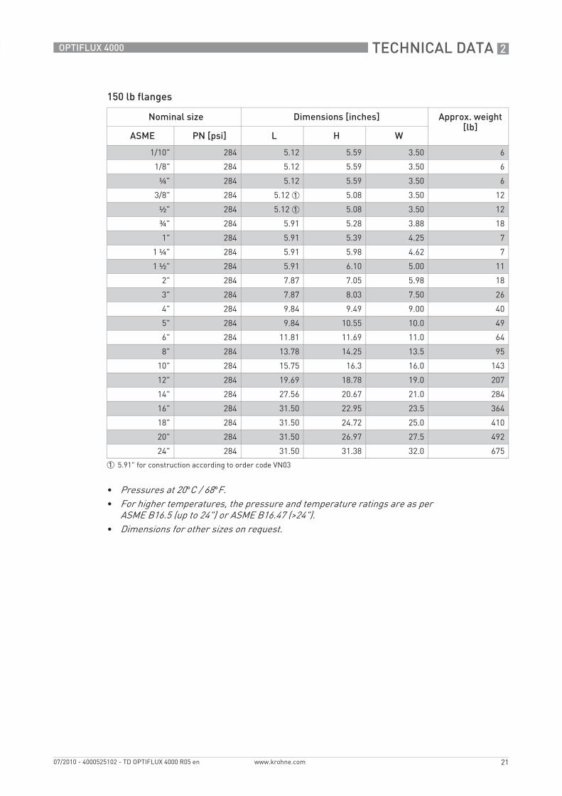
150 lb flanges
Nominal size Dimensions [inches] Approx. weight [lb]
ASME PN [psi] L H W
1/10" 284 5.12 5.59 3.50 6
1/8" 284 5.12 5.59 3.50 6
¼" 284 5.12 5.59 3.50 6
3/8" 284 5.12 1 5.08 3.50 12
½" 284 5.12 1 5.08 3.50 12
¾" 284 5.91 5.28 3.88 18
1" 284 5.91 5.39 4.25 7
1 ¼" 284 5.91 5.98 4.62 7
1 ½" 284 5.91 6.10 5.00 11
2" 284 7.87 7.05 5.98 18
3" 284 7.87 8.03 7.50 26
4" 284 9.84 9.49 9.00 40
5" 284 9.84 10.55 10.0 49
6" 284 11.81 11.69 11.0 64
8" 284 13.78 14.25 13.5 95
10" 284 15.75 16.3 16.0 143
12" 284 19.69 18.78 19.0 207
14" 284 27.56 20.67 21.0 284
16" 284 31.50 22.95 23.5 364
18" 284 31.50 24.72 25.0 410
20" 284 31.50 26.97 27.5 492
24" 284 31.50 31.38 32.0 675
1 5.91" for construction according to order code VN03
• Pressures at 20°C / 68°F.• For higher temperatures, the pressure and temperature ratings are as per
ASME B16.5 (up to 24") or ASME B16.47 (>24").• Dimensions for other sizes on request.

2 TECHNICAL DATA
22
OPTIFLUX 4000
www.krohne.com 07/2010 - 4000525102 - TD OPTIFLUX 4000 R05 en
300 lb flanges
Nominal size Dimensions [inches] Approx. weight [lb]
ASME PN [psi] L H W
1/10" 741 5.12 5.59 3.75 6
1/8" 741 5.12 5.59 3.75 6
¼" 741 5.12 5.59 3.75 6
3/8" 741 5.12 1 5.24 3.75 15
½" 741 5.12 1 5.24 3.75 15
¾" 741 5.91 5.67 4.62 20
1" 741 5.91 5.71 4.87 11
1 ½" 741 7.87 6.65 6.13 13
2" 741 9.84 7.32 6.50 22
3" 741 9.84 8.43 8.25 31
4" 741 11.81 10.00 10.0 44
6" 741 12.60 12.44 12.5 73
8" 741 15.75 15.04 15.0 157
10" 741 19.69 17.05 17.5 247
12" 741 23.62 20.00 20.5 375
14" 741 27.56 21.65 23.0 474
16" 741 31.50 23.98 25.5 639
20" 741 31.50 28.46 30.5 937
24" 741 31.50 33.39 36.0 1345
1 5.91" for construction according to order code VN03
• Pressures at 20°C / 68°F.• For higher temperatures, the pressure and temperature ratings are as per
ASME B16.5 (up to 24") or ASME B16.47 (>24").• Dimensions for other sizes on request.
INSTALLATION 3
23
OPTIFLUX 4000
www.krohne.com07/2010 - 4000525102 - TD OPTIFLUX 4000 R05 en
3.1 Intended use
The measurement of volumetric flowrate of electrically conductive fluids. Basic measurement is the flow velocity upon which all other measurements are based.
3.2 Installation conditions
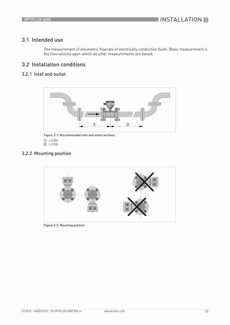
3.2.1 Inlet and outlet
3.2.2 Mounting position
Figure 3-1: Recommended inlet and outlet sections
1 ≥ 5 DN2 ≥ 2 DN
Figure 3-2: Mounting position
3 INSTALLATION
24
OPTIFLUX 4000
www.krohne.com 07/2010 - 4000525102 - TD OPTIFLUX 4000 R05 en
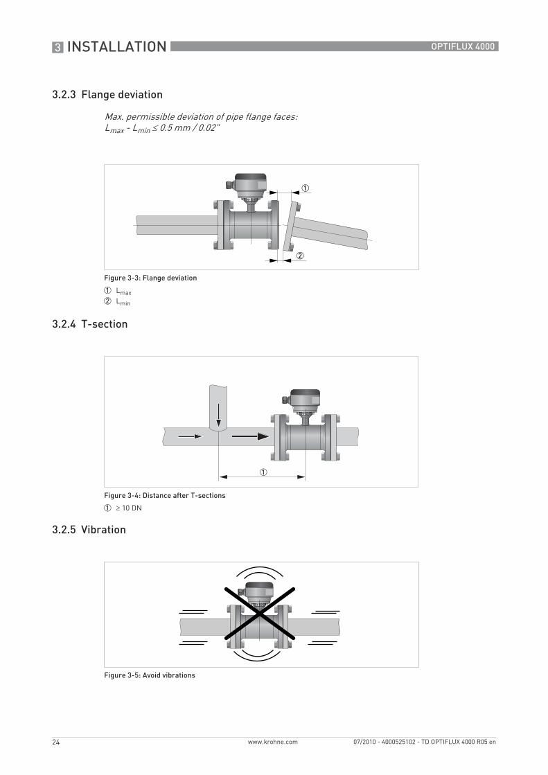
3.2.3 Flange deviation
3.2.4 T-section
3.2.5 Vibration
Max. permissible deviation of pipe flange faces: Lmax - Lmin ≤ 0.5 mm / 0.02"
Figure 3-3: Flange deviation
1 Lmax2 Lmin
Figure 3-4: Distance after T-sections
1 ≥ 10 DN
Figure 3-5: Avoid vibrations
INSTALLATION 3
25
OPTIFLUX 4000
www.krohne.com07/2010 - 4000525102 - TD OPTIFLUX 4000 R05 en
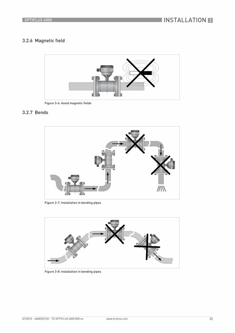
3.2.6 Magnetic field
3.2.7 Bends
Figure 3-6: Avoid magnetic fields
Figure 3-7: Installation in bending pipes
Figure 3-8: Installation in bending pipes
3 INSTALLATION
26
OPTIFLUX 4000
www.krohne.com 07/2010 - 4000525102 - TD OPTIFLUX 4000 R05 en
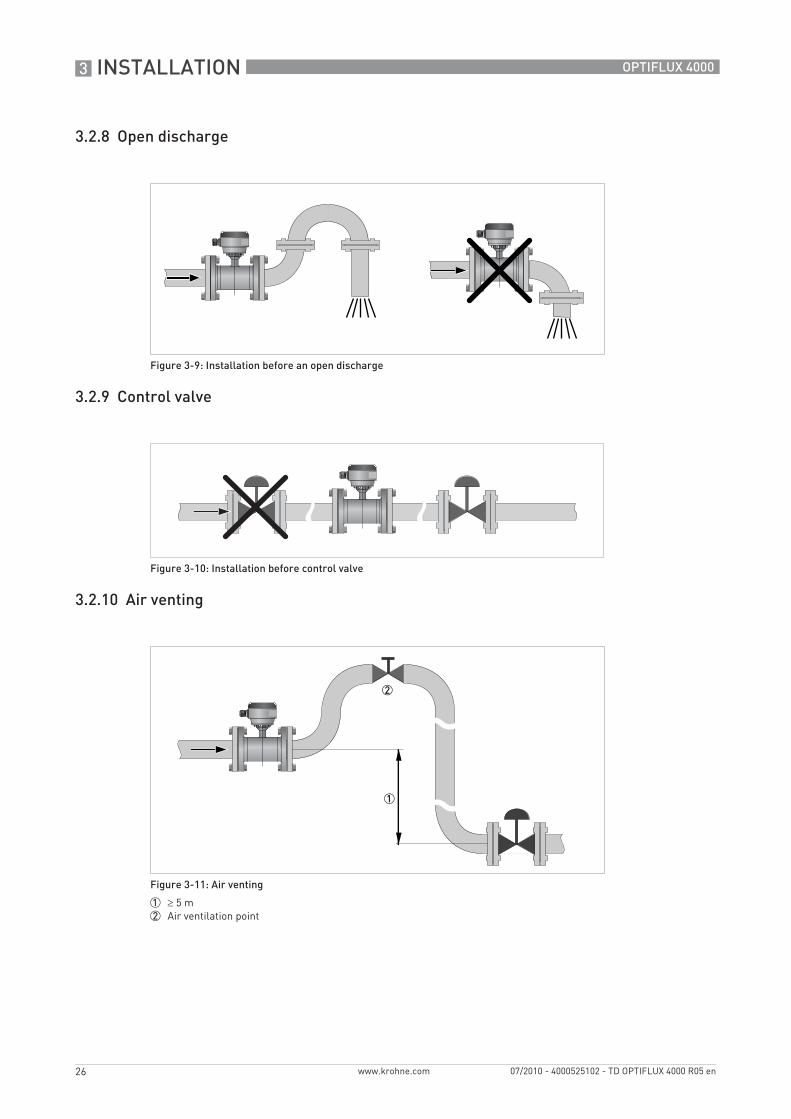
3.2.8 Open discharge
3.2.9 Control valve
3.2.10 Air venting
Figure 3-9: Installation before an open discharge
Figure 3-10: Installation before control valve
Figure 3-11: Air venting
1 ≥ 5 m2 Air ventilation point
INSTALLATION 3
27
OPTIFLUX 4000
www.krohne.com07/2010 - 4000525102 - TD OPTIFLUX 4000 R05 en
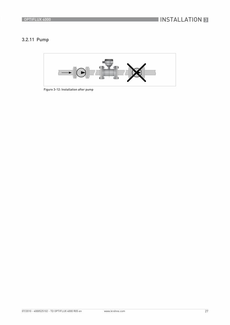
3.2.11 Pump
Figure 3-12: Installation after pump
4 ELECTRICAL CONNECTIONS
28
OPTIFLUX 4000
www.krohne.com 07/2010 - 4000525102 - TD OPTIFLUX 4000 R05 en
4.1 Safety instructions
4.2 Grounding
All work on the electrical connections may only be carried out with the power disconnected. Take note of the voltage data on the nameplate!
Observe the national regulations for electrical installations!
For devices used in hazardous areas, additional safety notes apply; please refer to the Ex documentation.
Observe without fail the local occupational health and safety regulations. Any work done on the electrical components of the measuring device may only be carried out by properly trained specialists.
Look at the device nameplate to ensure that the device is delivered according to your order. Check for the correct supply voltage printed on the nameplate.
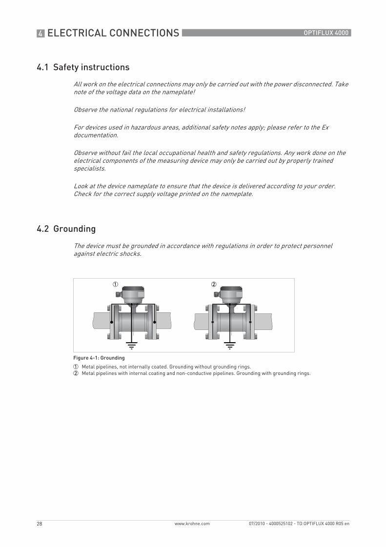
The device must be grounded in accordance with regulations in order to protect personnel against electric shocks.
Figure 4-1: Grounding
1 Metal pipelines, not internally coated. Grounding without grounding rings.2 Metal pipelines with internal coating and non-conductive pipelines. Grounding with grounding rings.
ELECTRICAL CONNECTIONS 4
29
OPTIFLUX 4000
www.krohne.com07/2010 - 4000525102 - TD OPTIFLUX 4000 R05 en
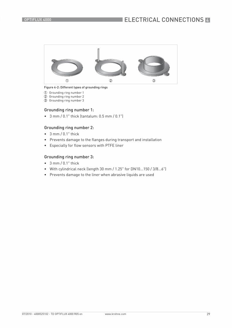
Grounding ring number 1:• 3 mm / 0.1" thick (tantalum: 0.5 mm / 0.1")
Grounding ring number 2:• 3 mm / 0.1" thick• Prevents damage to the flanges during transport and installation• Especially for flow sensors with PTFE liner
Grounding ring number 3:• 3 mm / 0.1" thick• With cylindrical neck (length 30 mm / 1.25" for DN10...150 / 3/8...6")• Prevents damage to the liner when abrasive liquids are used
Figure 4-2: Different types of grounding rings
1 Grounding ring number 12 Grounding ring number 23 Grounding ring number 3
4 ELECTRICAL CONNECTIONS
30
OPTIFLUX 4000
www.krohne.com 07/2010 - 4000525102 - TD OPTIFLUX 4000 R05 en
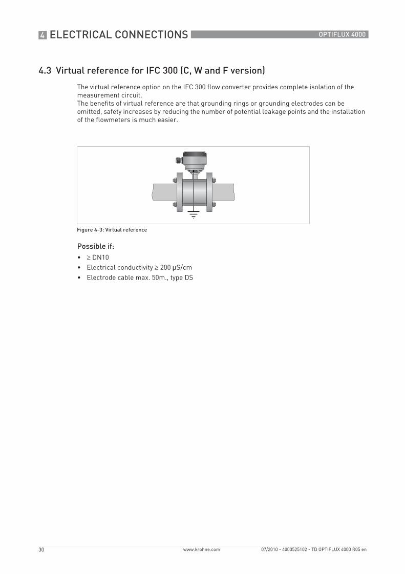
4.3 Virtual reference for IFC 300 (C, W and F version)
The virtual reference option on the IFC 300 flow converter provides complete isolation of the measurement circuit. The benefits of virtual reference are that grounding rings or grounding electrodes can be omitted, safety increases by reducing the number of potential leakage points and the installation of the flowmeters is much easier.
Possible if:• ≥ DN10• Electrical conductivity ≥ 200 µS/cm• Electrode cable max. 50m., type DS
Figure 4-3: Virtual reference
NOTES 5
31
OPTIFLUX 4000
www.krohne.com07/2010 - 4000525102 - TD OPTIFLUX 4000 R05 en
KROHNE product overview
• Electromagnetic flowmeters
• Variable area flowmeters
• Ultrasonic flowmeters
• Mass flowmeters
• Vortex flowmeters
• Flow controllers
• Level meters
• Temperature meters
• Pressure meters
• Analysis products
• Measuring systems for the oil and gas industry
• Measuring systems for sea-going tankers
Head Office KROHNE Messtechnik GmbHLudwig-Krohne-Str. 5D-47058 Duisburg (Germany)Tel.:+49 (0)203 301 0Fax:+49 (0)203 301 10389 [email protected]
© K
RO
HN
E 07
/201
0 -
4000
5251
02 -
TD
OP
TIFL
UX
4000
R05
en
- Su
bjec
t to
chan
ge w
ithou
t not
ice.
The current list of all KROHNE contacts and addresses can be found at:www.krohne.com
KK
K