optiflux 4000 - premier control technologies ltd. · in combination with the ifc 300 converter the...
TRANSCRIPT
OPTIFLUX 4000OPTIFLUX 4000OPTIFLUX 4000OPTIFLUX 4000 Technical DatasheetTechnical DatasheetTechnical DatasheetTechnical Datasheet
Electromagnetic flow sensor
• Robust, fully welded construction • Standard solutions for the widest range of industrial applications• Engineered solutions for very demanding applications
© KROHNE 04/2014 - 4000525103 - TD OPTIFLUX 4000 R06 en
The documentation is only complete when used in combination with the relevant documentation for the signal converter.
CONTENTS
2 www.krohne.com 04/2014 - 4000525103 - TD OPTIFLUX 4000 R06 en
OPTIFLUX 4000
1 Product features 3
1.1 The all-round solution for process industries................................................................. 31.2 Options.............................................................................................................................. 51.3 Measuring principle.......................................................................................................... 7
2 Technical data 8
2.1 Technical data................................................................................................................... 82.2 Legal metrology.............................................................................................................. 15
2.2.1 OIML R49 ............................................................................................................................... 152.2.2 MID Annex MI-001................................................................................................................. 172.2.3 Verification to MI-001 & OIML 49.......................................................................................... 192.2.4 OIML R117 ............................................................................................................................. 202.2.5 MI-005 ................................................................................................................................... 20
2.3 Measurement accuracy.................................................................................................. 212.4 Vacuum load ................................................................................................................... 232.5 Dimensions and weights ................................................................................................ 24
3 Installation 28
3.1 Intended use ................................................................................................................... 283.2 General notes on installation ......................................................................................... 28
3.2.1 Vibration ................................................................................................................................ 283.2.2 Magnetic field........................................................................................................................ 28
3.3 Installation conditions .................................................................................................... 293.3.1 Inlet and outlet ...................................................................................................................... 293.3.2 Bends in 2 or 3 dimensions................................................................................................... 293.3.3 T-section ............................................................................................................................... 293.3.4 Bends .................................................................................................................................... 303.3.5 Open feed or discharge......................................................................................................... 303.3.6 Flange deviation .................................................................................................................... 313.3.7 Pump ..................................................................................................................................... 313.3.8 Control valve ......................................................................................................................... 313.3.9 Air venting and vacuum forces ............................................................................................. 323.3.10 Mounting position................................................................................................................ 33
3.4 Mounting ......................................................................................................................... 333.4.1 Torques and pressures......................................................................................................... 33
4 Electrical connections 36
4.1 Safety instructions.......................................................................................................... 364.2 Grounding ....................................................................................................................... 364.3 Virtual reference for IFC 300 (C, W and F version) ........................................................ 38
5 Notes 39
PRODUCT FEATURES 1
3
OPTIFLUX 4000
www.krohne.com04/2014 - 4000525103 - TD OPTIFLUX 4000 R06 en
1.1 The all-round solution for process industries
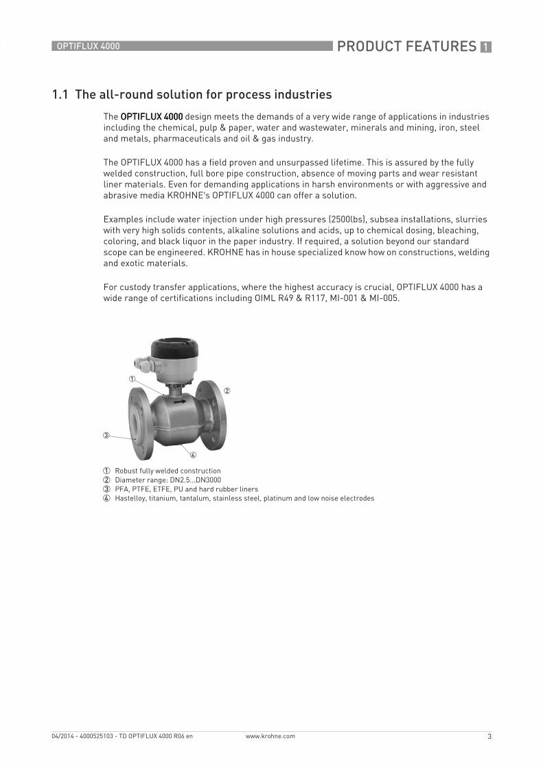
The OPTIFLUX 4000OPTIFLUX 4000OPTIFLUX 4000OPTIFLUX 4000 design meets the demands of a very wide range of applications in industries including the chemical, pulp & paper, water and wastewater, minerals and mining, iron, steel and metals, pharmaceuticals and oil & gas industry.
The OPTIFLUX 4000 has a field proven and unsurpassed lifetime. This is assured by the fully welded construction, full bore pipe construction, absence of moving parts and wear resistant liner materials. Even for demanding applications in harsh environments or with aggressive and abrasive media KROHNE’s OPTIFLUX 4000 can offer a solution.
Examples include water injection under high pressures (2500lbs), subsea installations, slurries with very high solids contents, alkaline solutions and acids, up to chemical dosing, bleaching, coloring, and black liquor in the paper industry. If required, a solution beyond our standard scope can be engineered. KROHNE has in house specialized know how on constructions, welding and exotic materials.
For custody transfer applications, where the highest accuracy is crucial, OPTIFLUX 4000 has a wide range of certifications including OIML R49 & R117, MI-001 & MI-005.
1 Robust fully welded construction2 Diameter range: DN2.5...DN30003 PFA, PTFE, ETFE, PU and hard rubber liners4 Hastelloy, titanium, tantalum, stainless steel, platinum and low noise electrodes
1 PRODUCT FEATURES
4
OPTIFLUX 4000
www.krohne.com 04/2014 - 4000525103 - TD OPTIFLUX 4000 R06 en
Highlights• Trusted and accepted flow sensor for all process applications• Proven in use and unsurpassed lifetime• Large installed base – more than 300.000 units - in virtually any industry• All welded rugged construction, to extend lifetime of equipment• Good corrosion, erosion / abrasion resistance• Wide choice of materials for housing & flanges including SS, Duplex, 6mo• Flexibility in sizes including sizes, special constructions, special inner diameters and
thicknesses• Corrosion resistant and leak tight electrodes. Specials (materials, retractable or pointed) on
demand• External coatings for offshore or subsoil installation. Optional paint specifications acc. to ISO
12944 – protective coating• Reliably measurement under very demanding conditions:
including high temperatures up to 180°C / 356°F, pressures up to 2500 bar, high solids contents (up to 70%)
• Bi-directional flow metering• Wide range of approvals for hazardous areas• Compliant with requirements for custody transfer OIML R49 & R117, MI-001 & MI-005• No grounding rings with virtual reference option on IFC 300• Extensive diagnostic capabilities• Every meter leaving the factory is wet calibrated on our calibration rigs which are traceable
Industries• Chemicals• Pulp & Paper• Water• Wastewater• Minerals & Mining• Iron, Steel & Metals• Pharmaceuticals• Oil & gas
Applications• For clean liquids • For slurries and pastes with high solids content• For abrasive and aggressive products
PRODUCT FEATURES 1
5
OPTIFLUX 4000
www.krohne.com04/2014 - 4000525103 - TD OPTIFLUX 4000 R06 en
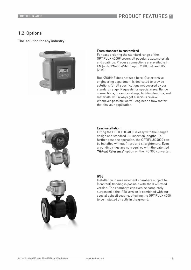
1.2 Options
The solution for any industry
From standard to customizedFrom standard to customizedFrom standard to customizedFrom standard to customizedFor easy ordering the standard range of the OPTIFLUX 4000F covers all popular sizes,materials and coatings. Process connections are available in EN (up to PN40), ASME ( up to 2500 lbs), and JIS (20K).
But KROHNE does not stop here. Our extensive engineering department is dedicated to provide solutions for all specifications not covered by our standard range. Requests for special sizes, flange connections, pressure ratings, building lengths, and materials, will always get a serious review. Whenever possible we will engineer a flow meter that fits your application.
Easy installationEasy installationEasy installationEasy installationFitting the OPTIFLUX 4000 is easy with the flanged design and standard ISO insertion lengths. To further ease the operation, the OPTIFLUX 4000 can be installed without filters and straighteners. Even grounding rings are not required with the patented "Virtual Reference""Virtual Reference""Virtual Reference""Virtual Reference" option on the IFC 300 converter.
IP68IP68IP68IP68Installation in measurement chambers subject to (constant) flooding is possible with the IP68 rated version. The chambers can even be completely surpassed if the IP68 version is combined with our special subsoil coating, allowing the OPTIFLUX 4000 to be installed directly in the ground.

1 PRODUCT FEATURES
6
OPTIFLUX 4000
www.krohne.com 04/2014 - 4000525103 - TD OPTIFLUX 4000 R06 en
Custody transferCustody transferCustody transferCustody transferIn combination with the IFC 300 converter the OPTIFLUX 4000 is suitable for custody transfer applications. It meets the requirements of OIML R49 and can be verified according to Annex MI-001 of the Measuring Instruments Directive (MID) for cold water and to OIML R117 and MID Annex MI-005 for liquids other than water.
All water meters for legal metrology purposes in Europe require certification under the MID. The EC type examination certificate for the OPTIFLUX 2300 is valid for the compact and the remote version and applies for forward and reverse flow.
Explosion safetyExplosion safetyExplosion safetyExplosion safetyIn combination with the IFC 100 or IFC 300 signal converter, the OPTIFLUX 4000 has received a wide range of approvals for hazardous areas, including ATEX, CSA, FM, IEC and Nepsi.
PRODUCT FEATURES 1
7
OPTIFLUX 4000
www.krohne.com04/2014 - 4000525103 - TD OPTIFLUX 4000 R06 en
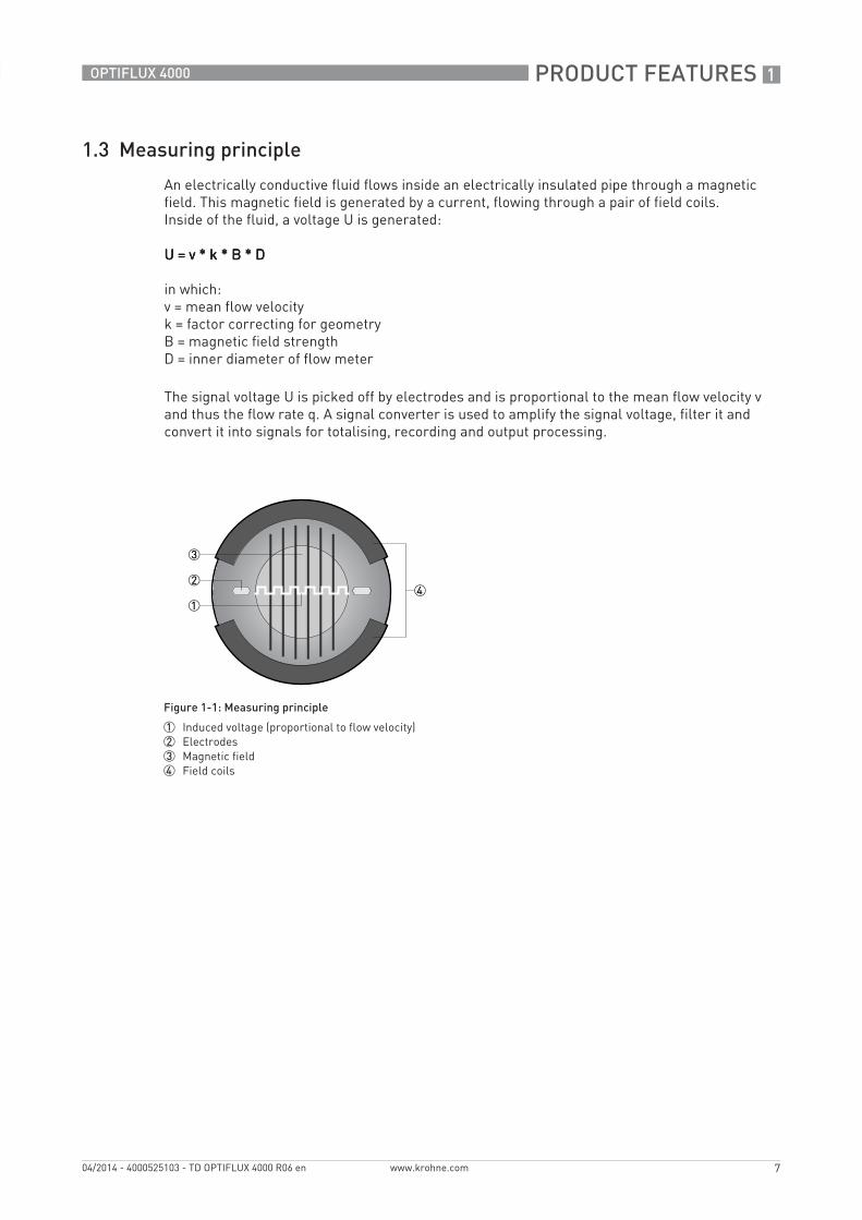
1.3 Measuring principle
An electrically conductive fluid flows inside an electrically insulated pipe through a magnetic field. This magnetic field is generated by a current, flowing through a pair of field coils.Inside of the fluid, a voltage U is generated:
U = v * k * B * DU = v * k * B * DU = v * k * B * DU = v * k * B * D
in which:v = mean flow velocityk = factor correcting for geometryB = magnetic field strengthD = inner diameter of flow meter
The signal voltage U is picked off by electrodes and is proportional to the mean flow velocity v and thus the flow rate q. A signal converter is used to amplify the signal voltage, filter it and convert it into signals for totalising, recording and output processing.
Figure 1-1: Measuring principle
1 Induced voltage (proportional to flow velocity)2 Electrodes3 Magnetic field4 Field coils
2 TECHNICAL DATA
8
OPTIFLUX 4000
www.krohne.com 04/2014 - 4000525103 - TD OPTIFLUX 4000 R06 en
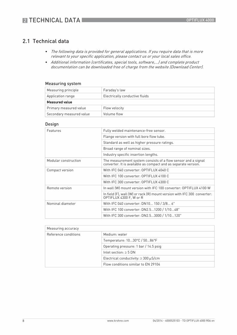
2.1 Technical data
• The following data is provided for general applications. If you require data that is more relevant to your specific application, please contact us or your local sales office.
• Additional information (certificates, special tools, software,...) and complete product documentation can be downloaded free of charge from the website (Download Center).
Measuring systemMeasuring principle Faraday's law
Application range Electrically conductive fluids
Measured valueMeasured valueMeasured valueMeasured value
Primary measured value Flow velocity
Secondary measured value Volume flow
DesignFeatures Fully welded maintenance-free sensor.
Flange version with full bore flow tube.
Standard as well as higher pressure ratings.
Broad range of nominal sizes.
Industry specific insertion lengths.
Modular construction The measurement system consists of a flow sensor and a signal converter. It is available as compact and as separate version.
Compact version With IFC 040 converter: OPTIFLUX 4040 C
With IFC 100 converter: OPTIFLUX 4100 C
With IFC 300 converter: OPTIFLUX 4300 C
Remote version In wall (W) mount version with IFC 100 converter: OPTIFLUX 4100 W
In field (F), wall (W) or rack (R) mount version with IFC 300 converter: OPTIFLUX 4300 F, W or R
Nominal diameter With IFC 040 converter: DN10... 150 / 3/8... 6"
With IFC 100 converter: DN2.5...1200 / 1/10...48"
With IFC 300 converter: DN2.5...3000 / 1/10...120"
Measuring accuracy
Reference conditions Medium: water
Temperature: 10...30°C / 50...86°F
Operating pressure: 1 bar / 14.5 psig
Inlet section: ≥ 5 DN
Electrical conductivity: ≥ 300 μS/cm
Flow conditions similar to EN 29104
TECHNICAL DATA 2
9
OPTIFLUX 4000
www.krohne.com04/2014 - 4000525103 - TD OPTIFLUX 4000 R06 en
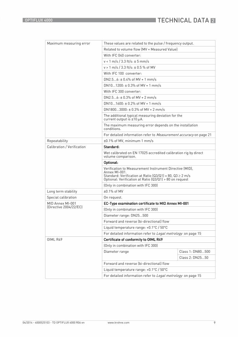
Maximum measuring error These values are related to the pulse / frequency output.
Related to volume flow (MV = Measured Value)
With IFC 040 converter:
v < 1 m/s / 3.3 ft/s: ± 5 mm/s
v > 1 m/s / 3.3 ft/s: ± 0.5 % of MV
With IFC 100 converter:
DN2.5...6: ± 0.4% of MV + 1 mm/s
DN10...1200: ± 0.3% of MV + 1 mm/s
With IFC 300 converter:
DN2.5...6: ± 0.3% of MV + 2 mm/s
DN10...1600: ± 0.2% of MV + 1 mm/s
DN1800...3000: ± 0.3% of MV + 2 mm/s
The additional typical measuring deviation for the current output is ±10 μA.
The maximum measuring error depends on the installation conditions.
For detailed information refer to Measurement accuracy on page 21
Repeatability ±0.1% of MV, minimum 1 mm/s
Calibration / Verification Standard: Standard: Standard: Standard:
Wet calibrated on EN 17025 accredited calibration rig by direct volume comparison.
Optional: Optional: Optional: Optional:
Verification to Measurement Instrument Directive (MID), Annex MI-001.Standard: Verification at Ratio (Q3/Q1) = 80, Q3 ≥ 2 m/sOptional: Verification at Ratio (Q3/Q1) > 80 on request
(Only in combination with IFC 300)
Long term stability ±0.1% of MV
Special calibration On request.
MID Annex MI-001(Directive 2004/22/EC)
EC-Type examination certificate to MID Annex MI-001EC-Type examination certificate to MID Annex MI-001EC-Type examination certificate to MID Annex MI-001EC-Type examination certificate to MID Annex MI-001
(Only in combination with IFC 300)
Diameter range: DN25...500
Forward and reverse (bi-directional) flow
Liquid temperature range: +0.1°C / 50°C
For detailed information refer to Legal metrology on page 15
OIML R49 Certificate of conformity to OIML R49Certificate of conformity to OIML R49Certificate of conformity to OIML R49Certificate of conformity to OIML R49
(Only in combination with IFC 300)
Diameter range Class 1: DN80...500
Class 2: DN25...50
Forward and reverse (bi-directional) flow
Liquid temperature range: +0.1°C / 50°C
For detailed information refer to Legal metrology on page 15
2 TECHNICAL DATA
10
OPTIFLUX 4000
www.krohne.com 04/2014 - 4000525103 - TD OPTIFLUX 4000 R06 en
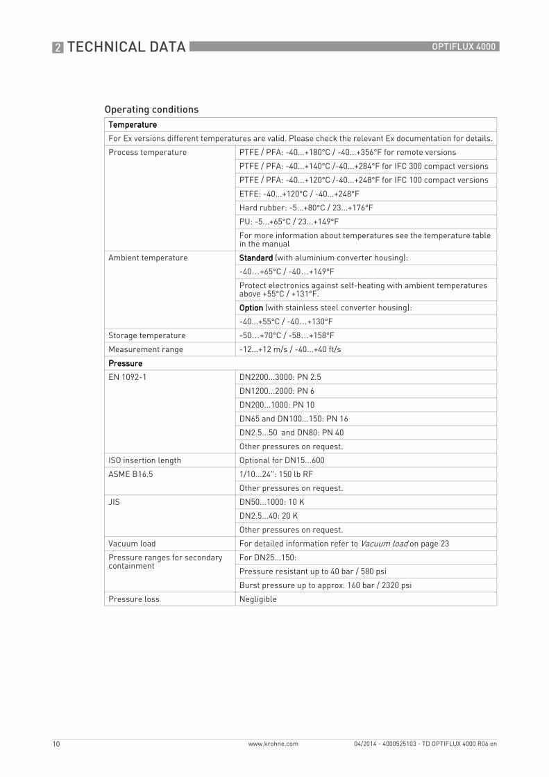
Operating conditionsTemperatureTemperatureTemperatureTemperature
For Ex versions different temperatures are valid. Please check the relevant Ex documentation for details.
Process temperature PTFE / PFA: -40...+180°C / -40...+356°F for remote versions
PTFE / PFA: -40...+140°C /-40...+284°F for IFC 300 compact versions
PTFE / PFA: -40...+120°C /-40...+248°F for IFC 100 compact versions
ETFE: -40...+120°C / -40...+248°F
Hard rubber: -5...+80°C / 23...+176°F
PU: -5...+65°C / 23...+149°F
For more information about temperatures see the temperature table in the manual
Ambient temperature StandardStandardStandardStandard (with aluminium converter housing):
-40…+65°C / -40…+149°F
Protect electronics against self-heating with ambient temperatures above +55°C / +131°F.
OptionOptionOptionOption (with stainless steel converter housing):
-40...+55°C / -40…+130°F
Storage temperature -50…+70°C / -58…+158°F
Measurement range -12...+12 m/s / -40...+40 ft/s
PressurePressurePressurePressure
EN 1092-1 DN2200...3000: PN 2.5
DN1200...2000: PN 6
DN200...1000: PN 10
DN65 and DN100...150: PN 16
DN2.5...50 and DN80: PN 40
Other pressures on request.
ISO insertion length Optional for DN15...600
ASME B16.5 1/10...24": 150 lb RF
Other pressures on request.
JIS DN50...1000: 10 K
DN2.5...40: 20 K
Other pressures on request.
Vacuum load For detailed information refer to Vacuum load on page 23
Pressure ranges for secondary containment
For DN25...150:
Pressure resistant up to 40 bar / 580 psi
Burst pressure up to approx. 160 bar / 2320 psi
Pressure loss Negligible
TECHNICAL DATA 2
11
OPTIFLUX 4000
www.krohne.com04/2014 - 4000525103 - TD OPTIFLUX 4000 R06 en
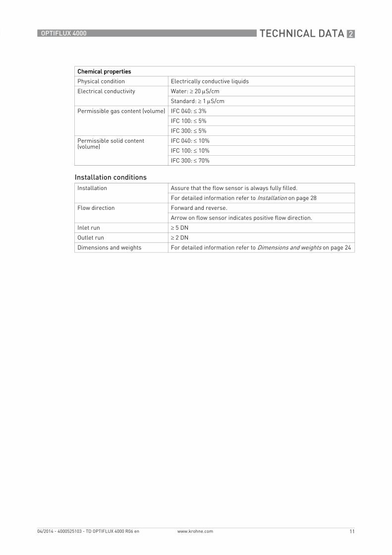
Chemical propertiesChemical propertiesChemical propertiesChemical properties
Physical condition Electrically conductive liquids
Electrical conductivity Water: ≥ 20 μS/cm
Standard: ≥ 1 μS/cm
Permissible gas content (volume) IFC 040: ≤ 3%
IFC 100: ≤ 5%
IFC 300: ≤ 5%
Permissible solid content (volume)
IFC 040: ≤ 10%
IFC 100: ≤ 10%
IFC 300: ≤ 70%
Installation conditionsInstallation Assure that the flow sensor is always fully filled.
For detailed information refer to Installation on page 28
Flow direction Forward and reverse.
Arrow on flow sensor indicates positive flow direction.
Inlet run ≥ 5 DN
Outlet run ≥ 2 DN
Dimensions and weights For detailed information refer to Dimensions and weights on page 24
2 TECHNICAL DATA
12
OPTIFLUX 4000
www.krohne.com 04/2014 - 4000525103 - TD OPTIFLUX 4000 R06 en
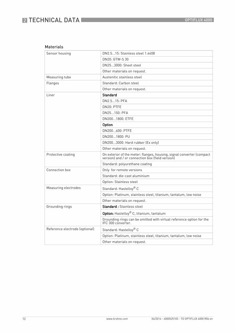
MaterialsSensor housing DN2.5...15: Stainless steel 1.4408
DN20: GTW-S 30
DN25...3000: Sheet steel
Other materials on request.
Measuring tube Austenitic stainless steel
Flanges Standard: Carbon steel
Other materials on request.
Liner StandardStandardStandardStandard
DN2.5...15: PFA
DN20: PTFE
DN25...150: PFA
DN200...1800: ETFE
OptionOptionOptionOption
DN200...600: PTFE
DN200...1800: PU
DN200...3000: Hard rubber (Ex only)
Other materials on request.
Protective coating On exterior of the meter: flanges, housing, signal converter (compact version) and / or connection box (field version)
Standard: polyurethane coating
Connection box Only for remote versions
Standard: die-cast aluminium
Option: Stainless steel
Measuring electrodes Standard: Hastelloy® C
Option: Platinum, stainless steel, titanium, tantalum, low noise
Other materials on request.
Grounding rings Standard :Standard :Standard :Standard : Stainless steel
Option:Option:Option:Option: Hastelloy® C, titanium, tantalum
Grounding rings can be omitted with virtual reference option for the IFC 300 converter.
Reference electrode (optional) Standard: Hastelloy® C
Option: Platinum, stainless steel, titanium, tantalum, low noise
Other materials on request.
TECHNICAL DATA 2
13
OPTIFLUX 4000
www.krohne.com04/2014 - 4000525103 - TD OPTIFLUX 4000 R06 en
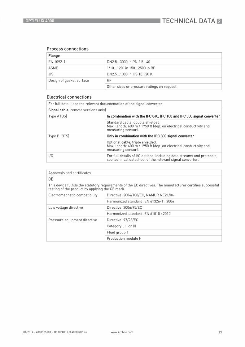
Process connectionsFlangeFlangeFlangeFlange
EN 1092-1 DN2.5...3000 in PN 2.5...40
ASME 1/10...120" in 150...2500 lb RF
JIS DN2.5...1000 in JIS 10...20 K
Design of gasket surface RF
Other sizes or pressure ratings on request.
Electrical connectionsFor full detail; see the relevant documentation of the signal converter
Signal cableSignal cableSignal cableSignal cable (remote versions only)
Type A (DS) In combination with the IFC 040, IFC 100 and IFC 300 signal converterIn combination with the IFC 040, IFC 100 and IFC 300 signal converterIn combination with the IFC 040, IFC 100 and IFC 300 signal converterIn combination with the IFC 040, IFC 100 and IFC 300 signal converter
Standard cable, double shielded.Max. length: 600 m / 1950 ft (dep. on electrical conductivity and measuring sensor).
Type B (BTS) Only in combination with the IFC 300 signal converterOnly in combination with the IFC 300 signal converterOnly in combination with the IFC 300 signal converterOnly in combination with the IFC 300 signal converter
Optional cable, triple shielded.Max. length: 600 m / 1950 ft (dep. on electrical conductivity and measuring sensor).
I/O For full details of I/O options, including data streams and protocols, see technical datasheet of the relevant signal converter.
Approvals and certificates
CECECECE
This device fulfills the statutory requirements of the EC directives. The manufacturer certifies successful testing of the product by applying the CE mark.
Electromagnetic compatibility Directive: 2004/108/EC, NAMUR NE21/04
Harmonized standard: EN 61326-1 : 2006
Low voltage directive Directive: 2006/95/EC
Harmonized standard: EN 61010 : 2010
Pressure equipment directive Directive: 97/23/EC
Category I, II or III
Fluid group 1
Production module H
2 TECHNICAL DATA
14
OPTIFLUX 4000
www.krohne.com 04/2014 - 4000525103 - TD OPTIFLUX 4000 R06 en
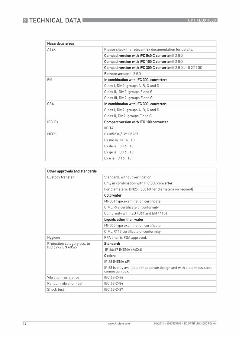
Hazardous areasHazardous areasHazardous areasHazardous areas
ATEX Please check the relevant Ex documentation for details.
Compact version with IFC 040 C converter:Compact version with IFC 040 C converter:Compact version with IFC 040 C converter:Compact version with IFC 040 C converter:II 2 GD
Compact version with IFC 100 C converter:Compact version with IFC 100 C converter:Compact version with IFC 100 C converter:Compact version with IFC 100 C converter:II 2 GD
Compact version with IFC 300 C converter:Compact version with IFC 300 C converter:Compact version with IFC 300 C converter:Compact version with IFC 300 C converter:II 2 GD or II 2(1) GD
Remote version:Remote version:Remote version:Remote version:II 2 GD
FM In combination with IFC 300 converter:In combination with IFC 300 converter:In combination with IFC 300 converter:In combination with IFC 300 converter:
Class I, Div 2, groups A, B, C and D
Class II, Div 2, groups F and G
Class III, Div 2, groups F and G
CSA In combination with IFC 300 converter:In combination with IFC 300 converter:In combination with IFC 300 converter:In combination with IFC 300 converter:
Class I, Div 2, groups A, B, C and D
Class II, Div 2, groups F and G
IEC-Ex Compact version with IFC 100 converter:Compact version with IFC 100 converter:Compact version with IFC 100 converter:Compact version with IFC 100 converter:
IIC T4
NEPSI GYJ05234 / GYJ05237
Ex me ia IIC T6...T3
Ex de ia IIC T6...T3
Ex qe ia IIC T6...T3
Ex e ia IIC T6...T3
Other approvals and standardsOther approvals and standardsOther approvals and standardsOther approvals and standards
Custody transfer Standard: without verification
Only in combination with IFC 300 converter.
For diameters: DN25...500 (other diameters on request)
Cold waterCold waterCold waterCold water
MI-001 type examination certificate
OIML R49 certificate of conformity
Conformity with ISO 4064 and EN 14154
Liquids other than waterLiquids other than waterLiquids other than waterLiquids other than water
MI-005 type examination certificate
OIML R117 certificate of conformity
Hygiene PFA liner is FDA approved.
Protection category acc. to IEC 529 / EN 60529
Standard:Standard:Standard:Standard:
IP 66/67 (NEMA 4/4X/6)
Option:Option:Option:Option:
IP 68 (NEMA 6P)
IP 68 is only available for separate design and with a stainless steel connection box.
Vibration resistance IEC 68-2-64
Random vibration test IEC 68-2-34
Shock test IEC 68-2-27
TECHNICAL DATA 2
15
OPTIFLUX 4000
www.krohne.com04/2014 - 4000525103 - TD OPTIFLUX 4000 R06 en
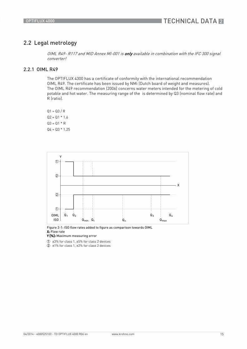
2.2 Legal metrology
2.2.1 OIML R49
The OPTIFLUX 4300 has a certificate of conformity with the international recommendation OIML R49. The certificate has been issued by NMi (Dutch board of weight and measures). The OIML R49 recommendation (2006) concerns water meters intended for the metering of cold potable and hot water. The measuring range of the is determined by Q3 (nominal flow rate) and R (ratio).
OIML R49- R117 and MID Annex MI-001 is onlyonlyonlyonly available in combination with the IFC 300 signal converter!
Q1 = Q3 / R
Q2 = Q1 * 1.6
Q3 = Q1 * R
Q4 = Q3 * 1.25
Figure 2-1: ISO flow rates added to figure as comparison towards OIMLX:X:X:X: Flow rateY [%]:Y [%]:Y [%]:Y [%]: Maximum measuring error
1 ±3% for class 1, ±5% for class 2 devices2 ±1% for class 1, ±2% for class 2 devices
2 TECHNICAL DATA
16
OPTIFLUX 4000
www.krohne.com 04/2014 - 4000525103 - TD OPTIFLUX 4000 R06 en
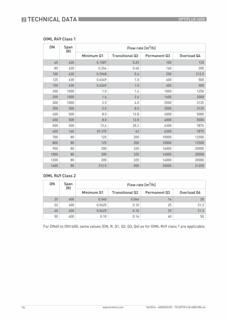
OIML R49 Class 1
OIML R49 Class 2
For DN65 to DN1600; same values (DN, R, Q1, Q2, Q3, Q4) as for OIML R49 class 1 are applicable.
DN Span (R)
Flow rate [m3/h]
Minimum Q1 Transitional Q2 Permanent Q3 Overload Q4
65 630 0.1587 0.25 100 125
80 630 0.254 0.40 160 200
100 630 0.3968 0.6 250 312.5
125 630 0.6349 1.0 400 500
150 630 0.6349 1.0 400 500
200 1000 1.0 1.6 1000 1250
250 1000 1.6 2.6 1600 2000
300 1000 2.5 4.0 2500 3125
350 500 5.0 8.0 2500 3125
400 500 8.0 12.8 4000 5000
450 500 8.0 12.8 4000 5000
500 500 12.6 20.2 6300 7875
600 160 39.375 63 6300 7875
700 80 125 200 10000 12500
800 80 125 200 10000 12500
900 80 200 320 16000 20000
1000 80 200 320 16000 20000
1200 80 200 320 16000 20000
1600 80 312.5 500 25000 31250
DN Span (R)
Flow rate [m3/h]
Minimum Q1 Transitional Q2 Permanent Q3 Overload Q4
25 400 0.040 0.064 16 20
32 400 0.0625 0.10 25 31.3
40 400 0.0625 0.10 25 31.3
50 400 0.10 0.16 40 50
TECHNICAL DATA 2
17
OPTIFLUX 4000
www.krohne.com04/2014 - 4000525103 - TD OPTIFLUX 4000 R06 en
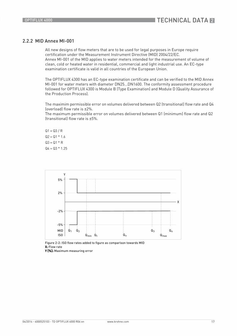
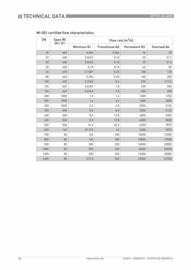
2.2.2 MID Annex MI-001
All new designs of flow meters that are to be used for legal purposes in Europe require certification under the Measurement Instrument Directive (MID) 2004/22/EC. Annex MI-001 of the MID applies to water meters intended for the measurement of volume of clean, cold or heated water in residential, commercial and light industrial use. An EC-type examination certificate is valid in all countries of the European Union.
The OPTIFLUX 4300 has an EC-type examination certificate and can be verified to the MID Annex MI-001 for water meters with diameter DN25...DN1600. The conformity assessment procedure followed for OPTIFLUX 4300 is Module B (Type Examination) and Module D (Quality Assurance of the Production Process).
The maximim permissible error on volumes delivered between Q2 (transitional) flow rate and Q4 (overload) flow rate is ±2%. The maximum permissible error on volumes delivered between Q1 (minimum) flow rate and Q2 (transitional) flow rate is ±5%.
Q1 = Q3 / R
Q2 = Q1 * 1.6
Q3 = Q1 * R
Q4 = Q3 * 1.25
Figure 2-2: ISO flow rates added to figure as comparison towards MIDX:X:X:X: Flow rateY [%]:Y [%]:Y [%]:Y [%]: Maximum measuring error
2 TECHNICAL DATA
18
OPTIFLUX 4000
www.krohne.com 04/2014 - 4000525103 - TD OPTIFLUX 4000 R06 en
MI-001 certified flow characteristics
DN Span (R)Q3 / Q1
Flow rate [m3/h]
Minimum Q1 Transitional Q2 Permanent Q3 Overload Q4
25 400 0.040 0.064 16 20
32 400 0.0625 0.10 25 31.3
40 400 0.0625 0.10 25 31.3
50 400 0.10 0.16 40 50
65 625 0.1587 0.25 100 125
80 640 0.254 0.40 160 200
100 625 0.3968 0.6 250 312.5
125 667 0.6349 1.0 400 500
150 667 0.6349 1.0 400 500
200 1000 1.0 1.6 1000 1250
250 1000 1.6 2.6 1600 2000
300 1000 2.5 4.0 2500 3125
350 500 5.0 8.0 2500 3125
400 500 8.0 12.8 4000 5000
450 500 8.0 12.8 4000 5000
500 500 12.6 20.2 6300 7875
600 160 39.375 63 6300 7875
700 80 125 200 10000 12500
800 80 125 200 10000 12500
900 80 200 320 16000 20000
1000 80 200 320 16000 20000
1200 80 200 320 16000 20000
1600 80 312.5 500 25000 31250
TECHNICAL DATA 2
19
OPTIFLUX 4000
www.krohne.com04/2014 - 4000525103 - TD OPTIFLUX 4000 R06 en
2.2.3 Verification to MI-001 & OIML 49
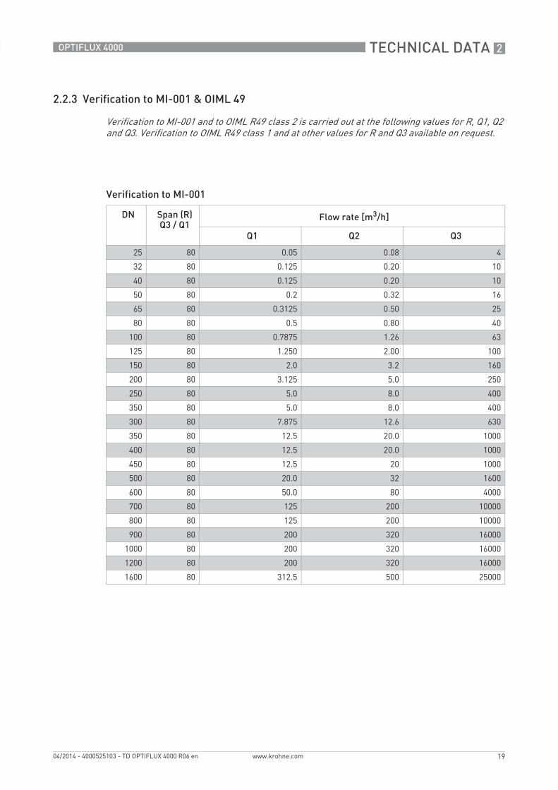
Verification to MI-001
Verification to MI-001 and to OIML R49 class 2 is carried out at the following values for R, Q1, Q2 and Q3. Verification to OIML R49 class 1 and at other values for R and Q3 available on request.
DN Span (R)Q3 / Q1
Flow rate [m3/h]
Q1 Q2 Q3
25 80 0.05 0.08 4
32 80 0.125 0.20 10
40 80 0.125 0.20 10
50 80 0.2 0.32 16
65 80 0.3125 0.50 25
80 80 0.5 0.80 40
100 80 0.7875 1.26 63
125 80 1.250 2.00 100
150 80 2.0 3.2 160
200 80 3.125 5.0 250
250 80 5.0 8.0 400
350 80 5.0 8.0 400
300 80 7.875 12.6 630
350 80 12.5 20.0 1000
400 80 12.5 20.0 1000
450 80 12.5 20 1000
500 80 20.0 32 1600
600 80 50.0 80 4000
700 80 125 200 10000
800 80 125 200 10000
900 80 200 320 16000
1000 80 200 320 16000
1200 80 200 320 16000
1600 80 312.5 500 25000
2 TECHNICAL DATA
20
OPTIFLUX 4000
www.krohne.com 04/2014 - 4000525103 - TD OPTIFLUX 4000 R06 en
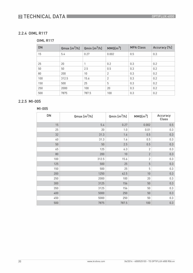
2.2.4 OIML R117
OIML R117
2.2.5 MI-005
MI-005
DN Qmax [m3/h] Qmin [m3/h] MMQ[m3] MPA Class Accuracy [%]
15 5.4 0.27 0.002 0.5 0.3
25 20 1 0.2 0.3 0.2
50 50 2.5 0.5 0.3 0.2
80 200 10 2 0.3 0.2
100 312.5 15.6 2 0.3 0.2
150 500 25 5 0.3 0.2
250 2000 100 20 0.3 0.2
500 7875 787.5 100 0.3 0.2
DN Qmax [m3/h] Qmin [m3/h] MMQ[m3] Accuracy Class
15 5.4 0.27 0.002 0.5
25 20 1.0 0.01 0.3
32 31.3 1.6 0.5 0.3
40 31.3 1.6 0.5 0.3
50 50 2.5 0.5 0.3
65 125 6.3 2 0.3
80 200 10 2 0.3
100 312.5 15.6 2 0.3
125 500 25 5 0.3
150 500 25 5 0.3
200 1250 62.5 10 0.3
250 2000 100 20 0.3
300 3125 156 50 0.3
350 3125 156 50 0.3
400 5000 250 50 0.3
450 5000 250 50 0.3
500 7875 787.5 100 0.3
TECHNICAL DATA 2
21
OPTIFLUX 4000
www.krohne.com04/2014 - 4000525103 - TD OPTIFLUX 4000 R06 en
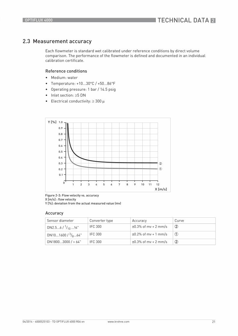
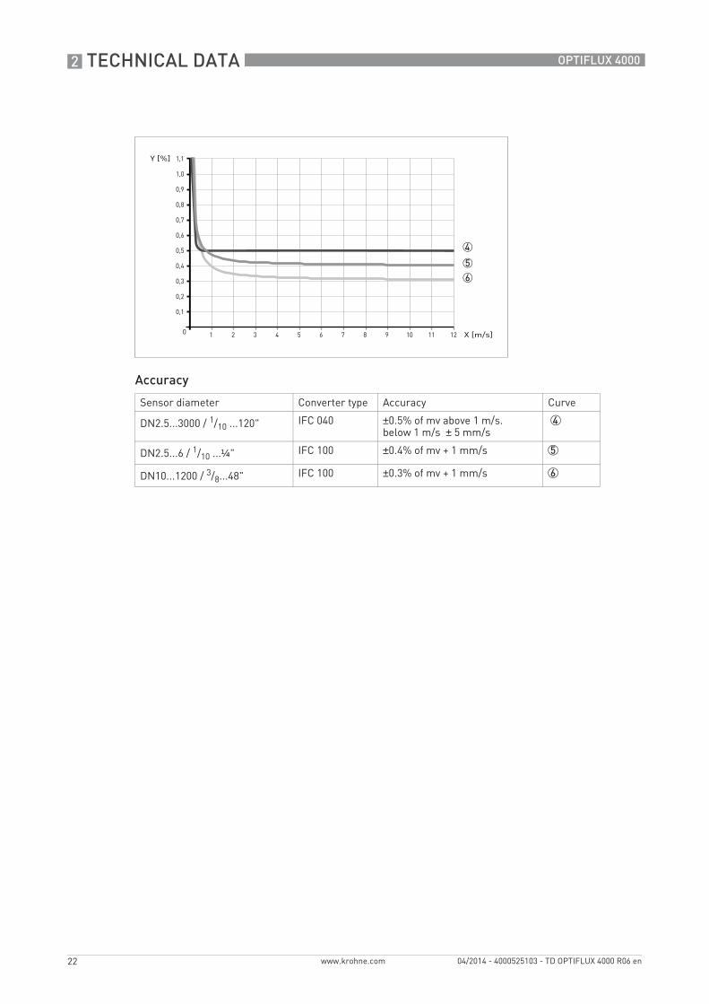
2.3 Measurement accuracy
Each flowmeter is standard wet calibrated under reference conditions by direct volume comparison. The performance of the flowmeter is defined and documented in an individual calibration certificate.
Reference conditions• Medium: water• Temperature: +10...30°C / +50...86°F• Operating pressure: 1 bar / 14.5 psig• Inlet section: ≥5 DN• Electrical conductivity: ≥ 300 μ
Accuracy
Figure 2-3: Flow velocity vs. accuracyX [m/s] : flow velocityY [%]: deviation from the actual measured value (mv)
Sensor diameter Converter type Accuracy Curve
DN2.5...6 / 1/10 ...¼" IFC 300 ±0.3% of mv + 2 mm/s 2
DN10...1600 / 3/8...64" IFC 300 ±0.2% of mv + 1 mm/s 1
DN1800...3000 / > 64" IFC 300 ±0.3% of mv + 2 mm/s 2
2 TECHNICAL DATA
22
OPTIFLUX 4000
www.krohne.com 04/2014 - 4000525103 - TD OPTIFLUX 4000 R06 en
Accuracy
Sensor diameter Converter type Accuracy Curve
DN2.5...3000 / 1/10 ...120" IFC 040 ±0.5% of mv above 1 m/s.below 1 m/s ± 5 mm/s
4
DN2.5...6 / 1/10 ...¼" IFC 100 ±0.4% of mv + 1 mm/s 5
DN10...1200 / 3/8...48" IFC 100 ±0.3% of mv + 1 mm/s 6
4
5
6
TECHNICAL DATA 2
23
OPTIFLUX 4000
www.krohne.com04/2014 - 4000525103 - TD OPTIFLUX 4000 R06 en
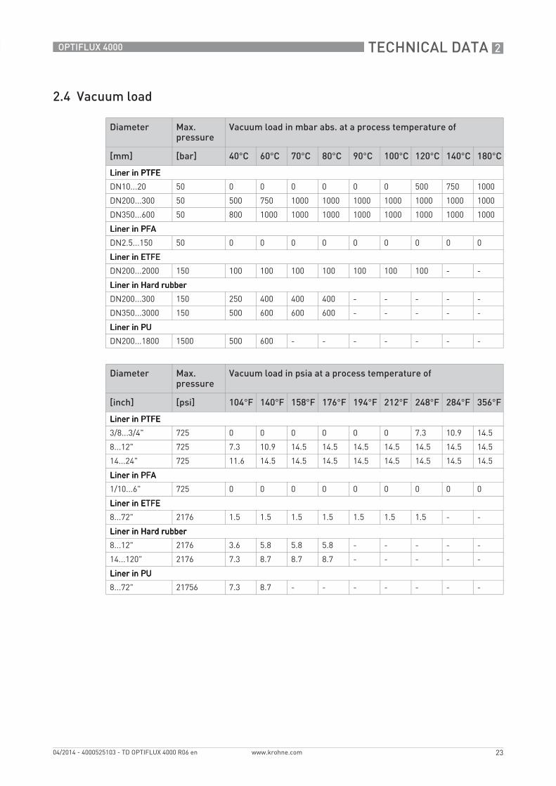
2.4 Vacuum load
Diameter Max. pressure
Vacuum load in mbar abs. at a process temperature of
[mm] [bar] 40°C 60°C 70°C 80°C 90°C 100°C 120°C 140°C 180°C
Liner in PTFELiner in PTFELiner in PTFELiner in PTFE
DN10...20 50 0 0 0 0 0 0 500 750 1000
DN200...300 50 500 750 1000 1000 1000 1000 1000 1000 1000
DN350...600 50 800 1000 1000 1000 1000 1000 1000 1000 1000
Liner in PFALiner in PFALiner in PFALiner in PFA
DN2.5...150 50 0 0 0 0 0 0 0 0 0
Liner in ETFELiner in ETFELiner in ETFELiner in ETFE
DN200...2000 150 100 100 100 100 100 100 100 - -
Liner in Hard rubberLiner in Hard rubberLiner in Hard rubberLiner in Hard rubber
DN200...300 150 250 400 400 400 - - - - -
DN350...3000 150 500 600 600 600 - - - - -
Liner in PULiner in PULiner in PULiner in PU
DN200...1800 1500 500 600 - - - - - - -
Diameter Max. pressure
Vacuum load in psia at a process temperature of
[inch] [psi] 104°F 140°F 158°F 176°F 194°F 212°F 248°F 284°F 356°F
Liner in PTFELiner in PTFELiner in PTFELiner in PTFE
3/8...3/4" 725 0 0 0 0 0 0 7.3 10.9 14.5
8...12" 725 7.3 10.9 14.5 14.5 14.5 14.5 14.5 14.5 14.5
14...24" 725 11.6 14.5 14.5 14.5 14.5 14.5 14.5 14.5 14.5
Liner in PFALiner in PFALiner in PFALiner in PFA
1/10...6" 725 0 0 0 0 0 0 0 0 0
Liner in ETFELiner in ETFELiner in ETFELiner in ETFE
8...72" 2176 1.5 1.5 1.5 1.5 1.5 1.5 1.5 - -
Liner in Hard rubberLiner in Hard rubberLiner in Hard rubberLiner in Hard rubber
8...12" 2176 3.6 5.8 5.8 5.8 - - - - -
14...120" 2176 7.3 8.7 8.7 8.7 - - - - -
Liner in PULiner in PULiner in PULiner in PU
8...72" 21756 7.3 8.7 - - - - - - -
2 TECHNICAL DATA
24
OPTIFLUX 4000
www.krohne.com 04/2014 - 4000525103 - TD OPTIFLUX 4000 R06 en
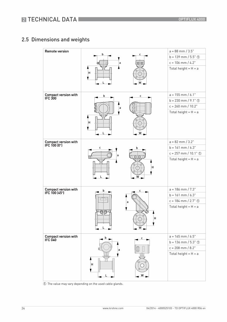
2.5 Dimensions and weights
Remote versionRemote versionRemote versionRemote version a = 88 mm / 3.5"
b = 139 mm / 5.5" 1
c = 106 mm / 4.2"
Total height = H + a
Compact version with Compact version with Compact version with Compact version with IFC 300IFC 300IFC 300IFC 300
a = 155 mm / 6.1"
b = 230 mm / 9.1" 1
c = 260 mm / 10.2"
Total height = H + a
Compact version with Compact version with Compact version with Compact version with IFC 100 (0IFC 100 (0IFC 100 (0IFC 100 (0°))))
a = 82 mm / 3.2"
b = 161 mm / 6.3"
c = 257 mm / 10.1" 1
Total height = H + a
Compact version with Compact version with Compact version with Compact version with IFC 100 (45IFC 100 (45IFC 100 (45IFC 100 (45°))))
a = 186 mm / 7.3"
b = 161 mm / 6.3"
c = 184 mm / 2.7" 1
Total height = H + a
Compact version with Compact version with Compact version with Compact version with IFC 040IFC 040IFC 040IFC 040
a = 165 mm / 6.5"
b = 136 mm / 5.3" 1
c = 208 mm / 8.2"
Total height = H + a
1 The value may vary depending on the used cable glands.
TECHNICAL DATA 2
25
OPTIFLUX 4000
www.krohne.com04/2014 - 4000525103 - TD OPTIFLUX 4000 R06 en
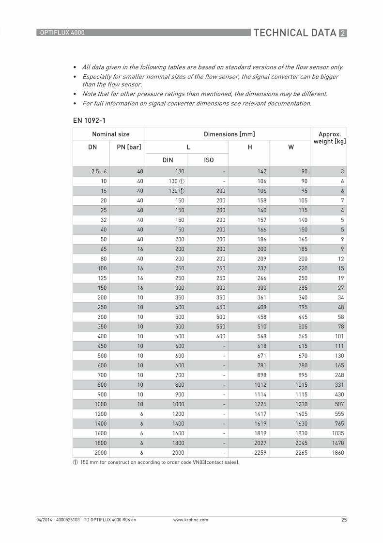
EN 1092-1
• All data given in the following tables are based on standard versions of the flow sensor only.• Especially for smaller nominal sizes of the flow sensor, the signal converter can be bigger
than the flow sensor.• Note that for other pressure ratings than mentioned, the dimensions may be different.• For full information on signal converter dimensions see relevant documentation.
Nominal size Dimensions [mm] Approx. weight [kg]
DN PN [bar] L H W
DIN ISO
2.5...6 40 130 - 142 90 3
10 40 130 1 - 106 90 6
15 40 130 1 200 106 95 6
20 40 150 200 158 105 7
25 40 150 200 140 115 4
32 40 150 200 157 140 5
40 40 150 200 166 150 5
50 40 200 200 186 165 9
65 16 200 200 200 185 9
80 40 200 200 209 200 12
100 16 250 250 237 220 15
125 16 250 250 266 250 19
150 16 300 300 300 285 27
200 10 350 350 361 340 34
250 10 400 450 408 395 48
300 10 500 500 458 445 58
350 10 500 550 510 505 78
400 10 600 600 568 565 101
450 10 600 - 618 615 111
500 10 600 - 671 670 130
600 10 600 - 781 780 165
700 10 700 - 898 895 248
800 10 800 - 1012 1015 331
900 10 900 - 1114 1115 430
1000 10 1000 - 1225 1230 507
1200 6 1200 - 1417 1405 555
1400 6 1400 - 1619 1630 765
1600 6 1600 - 1819 1830 1035
1800 6 1800 - 2027 2045 1470
2000 6 2000 - 2259 2265 1860
1 150 mm for construction according to order code VN03(contact sales).
2 TECHNICAL DATA
26
OPTIFLUX 4000
www.krohne.com 04/2014 - 4000525103 - TD OPTIFLUX 4000 R06 en
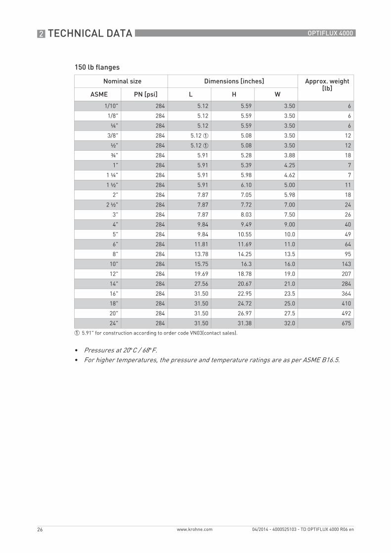
150 lb flanges
Nominal size Dimensions [inches] Approx. weight [lb]
ASME PN [psi] L H W
1/10" 284 5.12 5.59 3.50 6
1/8" 284 5.12 5.59 3.50 6
¼" 284 5.12 5.59 3.50 6
3/8" 284 5.12 1 5.08 3.50 12
½" 284 5.12 1 5.08 3.50 12
¾" 284 5.91 5.28 3.88 18
1" 284 5.91 5.39 4.25 7
1 ¼" 284 5.91 5.98 4.62 7
1 ½" 284 5.91 6.10 5.00 11
2" 284 7.87 7.05 5.98 18
2 ½" 284 7.87 7.72 7.00 24
3" 284 7.87 8.03 7.50 26
4" 284 9.84 9.49 9.00 40
5" 284 9.84 10.55 10.0 49
6" 284 11.81 11.69 11.0 64
8" 284 13.78 14.25 13.5 95
10" 284 15.75 16.3 16.0 143
12" 284 19.69 18.78 19.0 207
14" 284 27.56 20.67 21.0 284
16" 284 31.50 22.95 23.5 364
18" 284 31.50 24.72 25.0 410
20" 284 31.50 26.97 27.5 492
24" 284 31.50 31.38 32.0 675
1 5.91" for construction according to order code VN03(contact sales).
• Pressures at 20°C / 68°F.• For higher temperatures, the pressure and temperature ratings are as per ASME B16.5.
TECHNICAL DATA 2
27
OPTIFLUX 4000
www.krohne.com04/2014 - 4000525103 - TD OPTIFLUX 4000 R06 en
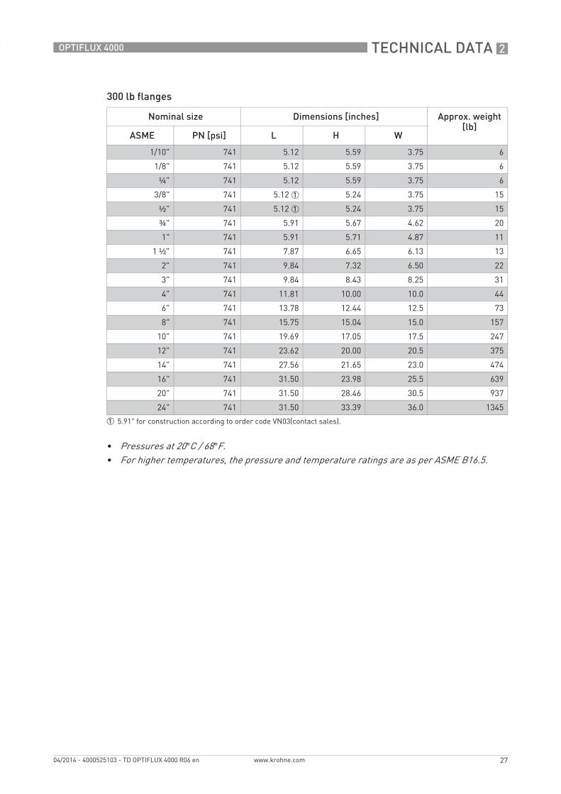
300 lb flanges
Nominal size Dimensions [inches] Approx. weight [lb]
ASME PN [psi] L H W
1/10" 741 5.12 5.59 3.75 6
1/8" 741 5.12 5.59 3.75 6
¼" 741 5.12 5.59 3.75 6
3/8" 741 5.12 1 5.24 3.75 15
½" 741 5.12 1 5.24 3.75 15
¾" 741 5.91 5.67 4.62 20
1" 741 5.91 5.71 4.87 11
1 ½" 741 7.87 6.65 6.13 13
2" 741 9.84 7.32 6.50 22
3" 741 9.84 8.43 8.25 31
4" 741 11.81 10.00 10.0 44
6" 741 13.78 12.44 12.5 73
8" 741 15.75 15.04 15.0 157
10" 741 19.69 17.05 17.5 247
12" 741 23.62 20.00 20.5 375
14" 741 27.56 21.65 23.0 474
16" 741 31.50 23.98 25.5 639
20" 741 31.50 28.46 30.5 937
24" 741 31.50 33.39 36.0 1345
1 5.91" for construction according to order code VN03(contact sales).
• Pressures at 20°C / 68°F.• For higher temperatures, the pressure and temperature ratings are as per ASME B16.5.
3 INSTALLATION
28
OPTIFLUX 4000
www.krohne.com 04/2014 - 4000525103 - TD OPTIFLUX 4000 R06 en
3.1 Intended use
The measurement of volumetric flowrate of electrically conductive fluids. Basic measurement is the flow velocity upon which all other measurements are based.
3.2 General notes on installation
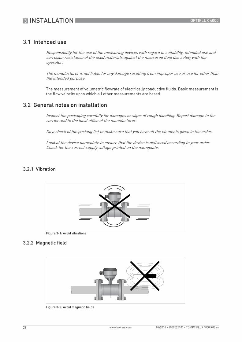
3.2.1 Vibration
3.2.2 Magnetic field
Responsibility for the use of the measuring devices with regard to suitability, intended use and corrosion resistance of the used materials against the measured fluid lies solely with the operator.
The manufacturer is not liable for any damage resulting from improper use or use for other than the intended purpose.
Inspect the packaging carefully for damages or signs of rough handling. Report damage to the carrier and to the local office of the manufacturer.
Do a check of the packing list to make sure that you have all the elements given in the order.
Look at the device nameplate to ensure that the device is delivered according to your order. Check for the correct supply voltage printed on the nameplate.
Figure 3-1: Avoid vibrations
Figure 3-2: Avoid magnetic fields
INSTALLATION 3
29
OPTIFLUX 4000
www.krohne.com04/2014 - 4000525103 - TD OPTIFLUX 4000 R06 en
3.3 Installation conditions
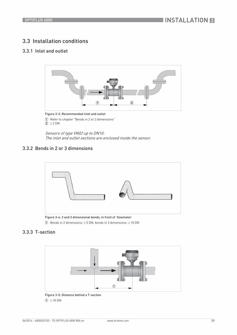
3.3.1 Inlet and outlet
3.3.2 Bends in 2 or 3 dimensions
3.3.3 T-section
Figure 3-3: Recommended inlet and outlet
1 Refer to chapter "Bends in 2 or 3 dimensions"2 ≥ 2 DN
Sensors of type VN02 up to DN10:The inlet and outlet sections are enclosed inside the sensor.
Figure 3-4: 2 and 3 dimensional bends, in front of flowmeter
1 Bends in 2 dimensions: ≥ 5 DN; bends in 3 dimensions: ≥ 10 DN
Figure 3-5: Distance behind a T-section
1 ≥ 10 DN
3 INSTALLATION
30
OPTIFLUX 4000
www.krohne.com 04/2014 - 4000525103 - TD OPTIFLUX 4000 R06 en
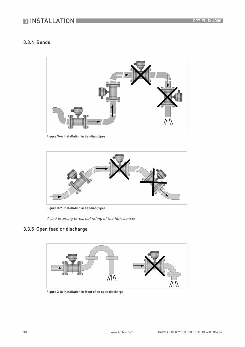
3.3.4 Bends
3.3.5 Open feed or discharge
Figure 3-6: Installation in bending pipes
Figure 3-7: Installation in bending pipes
Avoid draining or partial filling of the flow sensor
Figure 3-8: Installation in front of an open discharge
INSTALLATION 3
31
OPTIFLUX 4000
www.krohne.com04/2014 - 4000525103 - TD OPTIFLUX 4000 R06 en
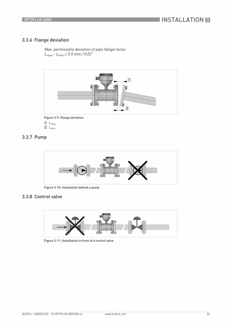
3.3.6 Flange deviation
3.3.7 Pump
3.3.8 Control valve
Max. permissible deviation of pipe flange faces: Lmax - Lmin ≤ 0.5 mm / 0.02"
Figure 3-9: Flange deviation
1 Lmax2 Lmin
Figure 3-10: Installation behind a pump
Figure 3-11: Installation in front of a control valve
3 INSTALLATION
32
OPTIFLUX 4000
www.krohne.com 04/2014 - 4000525103 - TD OPTIFLUX 4000 R06 en
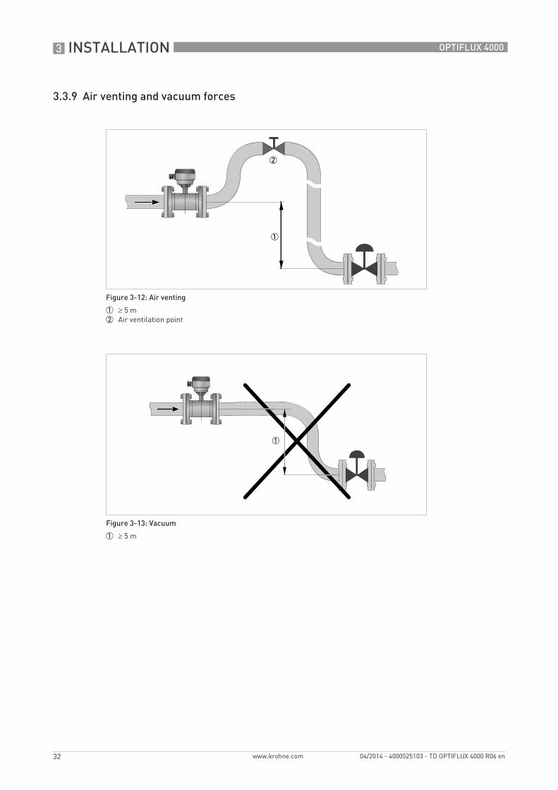
3.3.9 Air venting and vacuum forces
Figure 3-12: Air venting
1 ≥ 5 m2 Air ventilation point
Figure 3-13: Vacuum
1 ≥ 5 m
INSTALLATION 3
33
OPTIFLUX 4000
www.krohne.com04/2014 - 4000525103 - TD OPTIFLUX 4000 R06 en
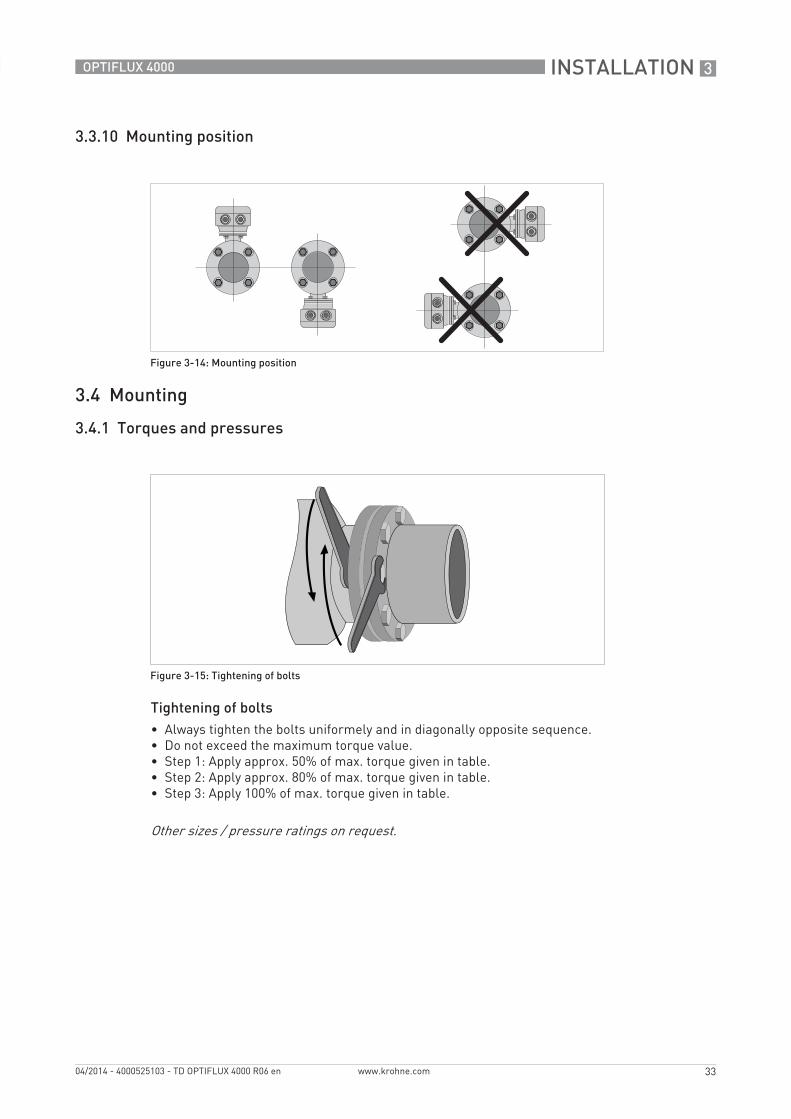
3.3.10 Mounting position
3.4 Mounting
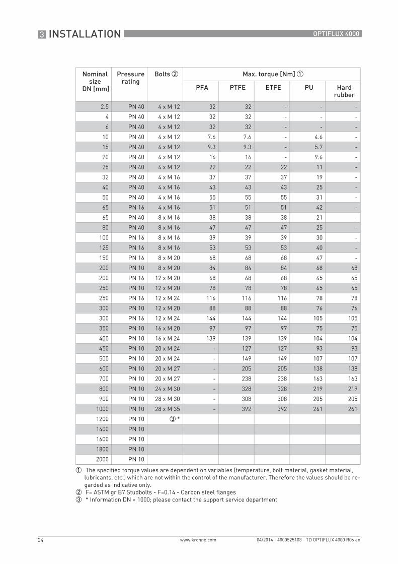
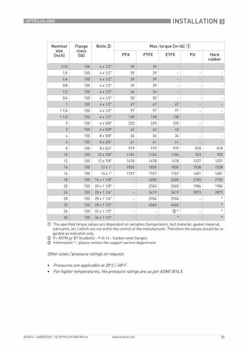
3.4.1 Torques and pressures
Tightening of bolts• Always tighten the bolts uniformely and in diagonally opposite sequence.• Do not exceed the maximum torque value.• Step 1: Apply approx. 50% of max. torque given in table.• Step 2: Apply approx. 80% of max. torque given in table.• Step 3: Apply 100% of max. torque given in table.
Figure 3-14: Mounting position
Figure 3-15: Tightening of bolts
Other sizes / pressure ratings on request.
3 INSTALLATION
34
OPTIFLUX 4000
www.krohne.com 04/2014 - 4000525103 - TD OPTIFLUX 4000 R06 en
Nominal size
DN [mm]
Pressurerating
Bolts 2 Max. torque [Nm] 1
PFA PTFE ETFE PU Hard rubber
2.5 PN 40 4 x M 12 32 32 - - -
4 PN 40 4 x M 12 32 32 - - -
6 PN 40 4 x M 12 32 32 - - -
10 PN 40 4 x M 12 7.6 7.6 - 4.6 -
15 PN 40 4 x M 12 9.3 9.3 - 5.7 -
20 PN 40 4 x M 12 16 16 - 9.6 -
25 PN 40 4 x M 12 22 22 22 11 -
32 PN 40 4 x M 16 37 37 37 19 -
40 PN 40 4 x M 16 43 43 43 25 -
50 PN 40 4 x M 16 55 55 55 31 -
65 PN 16 4 x M 16 51 51 51 42 -
65 PN 40 8 x M 16 38 38 38 21 -
80 PN 40 8 x M 16 47 47 47 25 -
100 PN 16 8 x M 16 39 39 39 30 -
125 PN 16 8 x M 16 53 53 53 40 -
150 PN 16 8 x M 20 68 68 68 47 -
200 PN 10 8 x M 20 84 84 84 68 68
200 PN 16 12 x M 20 68 68 68 45 45
250 PN 10 12 x M 20 78 78 78 65 65
250 PN 16 12 x M 24 116 116 116 78 78
300 PN 10 12 x M 20 88 88 88 76 76
300 PN 16 12 x M 24 144 144 144 105 105
350 PN 10 16 x M 20 97 97 97 75 75
400 PN 10 16 x M 24 139 139 139 104 104
450 PN 10 20 x M 24 - 127 127 93 93
500 PN 10 20 x M 24 - 149 149 107 107
600 PN 10 20 x M 27 - 205 205 138 138
700 PN 10 20 x M 27 - 238 238 163 163
800 PN 10 24 x M 30 - 328 328 219 219
900 PN 10 28 x M 30 - 308 308 205 205
1000 PN 10 28 x M 35 - 392 392 261 261
1200 PN 10 3 *
1400 PN 10
1600 PN 10
1800 PN 10
2000 PN 10
1 The specified torque values are dependent on variables (temperature, bolt material, gasket material,lubricants, etc.) which are not within the control of the manufacturer. Therefore the values should be re-garded as indicative only.
2 F= ASTM gr B7 Studbolts - F=0.14 - Carbon steel flanges3 * Information DN > 1000; please contact the support service department
INSTALLATION 3
35
OPTIFLUX 4000
www.krohne.com04/2014 - 4000525103 - TD OPTIFLUX 4000 R06 en
Nominal size
[inch]
Flange class [lb]
Bolts 2 Max. torque [in-lb] 1
PFA PTFE ETFE PU Hard rubber
1/10 150 4 x 1/2" 39 39 - - -
1/6 150 4 x 1/2" 39 39 - - -
1/4 150 4 x 1/2" 39 39 - - -
3/8 150 4 x 1/2" 39 39 - - -
1/2 150 4 x 1/2" 34 34 - - -
3/4 150 4 x 1/2" 50 50 - - -
1 150 4 x 1/2" 67 67 67 - -
1 1/4 150 4 x 1/2" 97 97 97 - -
1 1/2 150 4 x 1/2" 138 138 138 - -
2 150 4 x 5/8" 225 225 225 - -
3 150 4 x 5/8" 43 43 43 - -
4 150 8 x 5/8" 34 34 34 - -
6 150 8 x 3/4" 61 61 61 - -
8 150 8 x 3/4" 979 979 979 818 818
10 150 12 x 7/8" 1104 1104 1104 923 923
12 150 12 x 7/8" 1478 1478 1478 1237 1237
14 150 12 x 1" 1835 1835 1835 1538 1538
16 150 16 x 1" 1767 1767 1767 1481 1481
18 150 16 x 1 1/8" - 2605 2605 2183 2183
20 150 20 x 1 1/8" - 2365 2365 1984 1984
24 150 20 x 1 1/4" - 3419 3419 2873 2873
28 150 28 x 1 1/4" - 2904 2904 - *
32 150 28 x 1 1/2" - 4560 4560 - *
36 150 32 x 1 1/2" - - 3 * - *
40 150 36 x 1 1/2" - - * - *
1 The specified torque values are dependent on variables (temperature, bolt material, gasket material,lubricants, etc.) which are not within the control of the manufacturer. Therefore the values should be re-garded as indicative only.
2 F= ASTM gr B7 Studbolts - F=0.14 - Carbon steel flanges3 Information * ; please contact the support service department
Other sizes / pressure ratings on request.
• Pressures are applicable at 20°C / 68°F.• For higher temperatures, the pressure ratings are as per ASME B16.5.
4 ELECTRICAL CONNECTIONS
36
OPTIFLUX 4000
www.krohne.com 04/2014 - 4000525103 - TD OPTIFLUX 4000 R06 en
4.1 Safety instructions
4.2 Grounding
All work on the electrical connections may only be carried out with the power disconnected. Take note of the voltage data on the nameplate!
Observe the national regulations for electrical installations!
Observe without fail the local occupational health and safety regulations. Any work done on the electrical components of the measuring device may only be carried out by properly trained specialists.
Look at the device nameplate to ensure that the device is delivered according to your order. Check for the correct supply voltage printed on the nameplate.
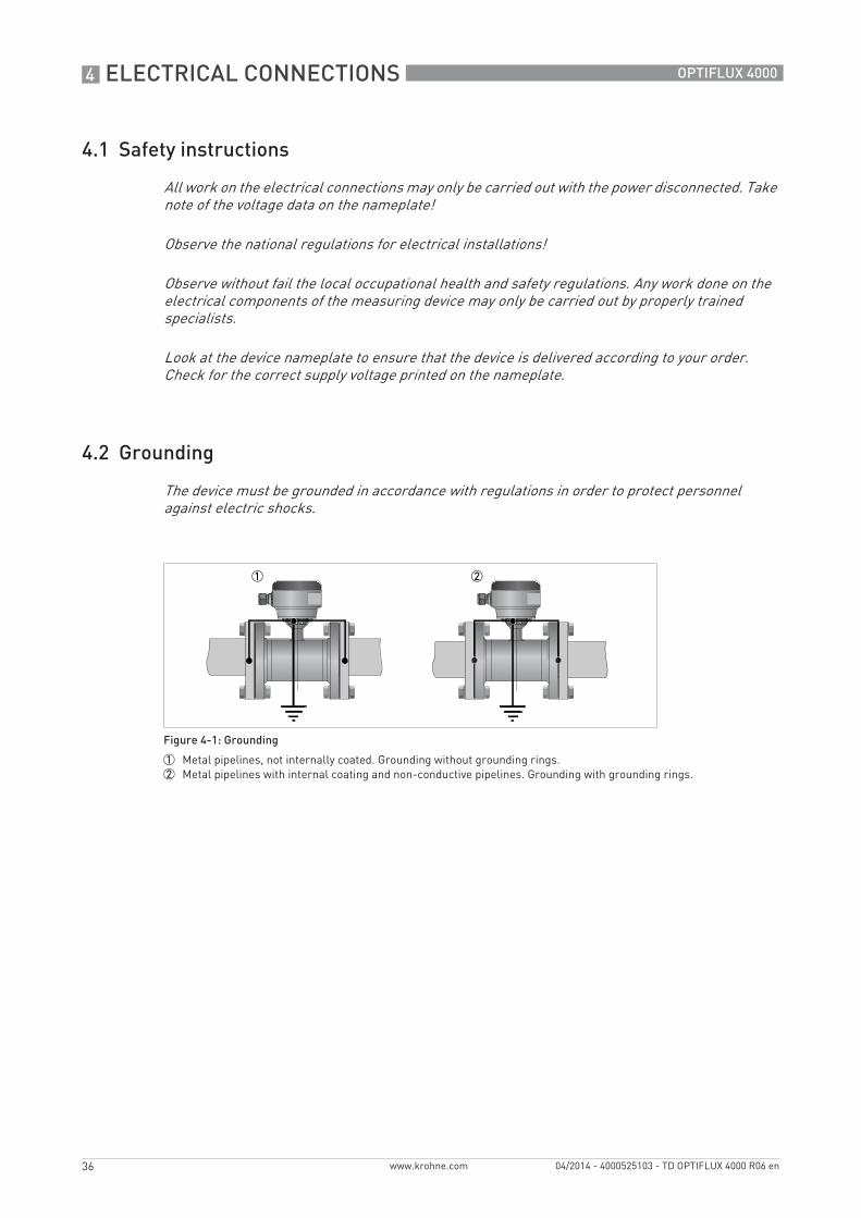
The device must be grounded in accordance with regulations in order to protect personnel against electric shocks.
Figure 4-1: Grounding
1 Metal pipelines, not internally coated. Grounding without grounding rings.2 Metal pipelines with internal coating and non-conductive pipelines. Grounding with grounding rings.
ELECTRICAL CONNECTIONS 4
37
OPTIFLUX 4000
www.krohne.com04/2014 - 4000525103 - TD OPTIFLUX 4000 R06 en
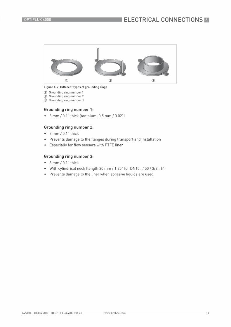
Grounding ring number 1:• 3 mm / 0.1" thick (tantalum: 0.5 mm / 0.02")
Grounding ring number 2:• 3 mm / 0.1" thick• Prevents damage to the flanges during transport and installation• Especially for flow sensors with PTFE liner
Grounding ring number 3:• 3 mm / 0.1" thick• With cylindrical neck (length 30 mm / 1.25" for DN10...150 / 3/8...6")• Prevents damage to the liner when abrasive liquids are used
Figure 4-2: Different types of grounding rings
1 Grounding ring number 12 Grounding ring number 23 Grounding ring number 3
4 ELECTRICAL CONNECTIONS
38
OPTIFLUX 4000
www.krohne.com 04/2014 - 4000525103 - TD OPTIFLUX 4000 R06 en
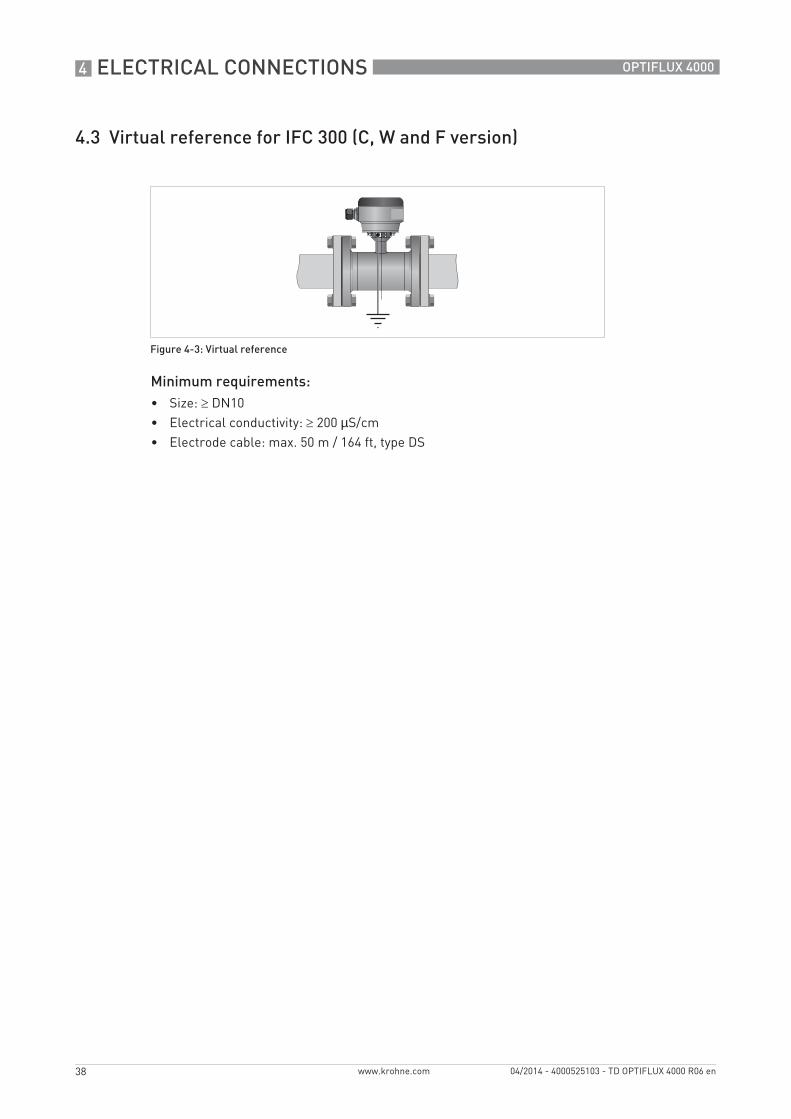
4.3 Virtual reference for IFC 300 (C, W and F version)
Minimum requirements:• Size: ≥ DN10• Electrical conductivity: ≥ 200 µS/cm• Electrode cable: max. 50 m / 164 ft, type DS
Figure 4-3: Virtual reference
NOTES 5
39
OPTIFLUX 4000
www.krohne.com04/2014 - 4000525103 - TD OPTIFLUX 4000 R06 en
KROHNE product overview
• Electromagnetic flowmeters
• Variable area flowmeters
• Ultrasonic flowmeters
• Mass flowmeters
• Vortex flowmeters
• Flow controllers
• Level meters
• Temperature assemblies
• Pressure transmitters
• Analysis products
• Products and systems for the oil & gas industry
• Measuring systems for the marine industry
Head Office KROHNE Messtechnik GmbHLudwig-Krohne-Str. 547058 Duisburg (Germany)Tel.:+49 203 301 0Fax:+49 203 301 103 89 [email protected]
© K
RO
HN
E 04
/201
4 -
4000
5251
03 -
TD
OP
TIFL
UX
4000
R06
en
- Su
bjec
t to
chan
ge w
ithou
t not
ice.
The current list of all KROHNE contacts and addresses can be found at:www.krohne.com