originally published in: research collection ieee
TRANSCRIPT

Research Collection
Journal Article
Integration of Six-Phase EV Drivetrains Into Battery ChargingProcess With Direct Grid Connection
Author(s): Subotic, Ivan; Bodo, Nandor; Levi, Emil
Publication Date: 2017-09
Permanent Link: https://doi.org/10.3929/ethz-b-000190947
Originally published in: IEEE Transactions on Energy Conversion 32(3), http://doi.org/10.1109/TEC.2017.2679280
Rights / License: Creative Commons Attribution 3.0 Unported
This page was generated automatically upon download from the ETH Zurich Research Collection. For moreinformation please consult the Terms of use.
ETH Library
1012 IEEE TRANSACTIONS ON ENERGY CONVERSION, VOL. 32, NO. 3, SEPTEMBER 2017
Integration of Six-Phase EV Drivetrains Into BatteryCharging Process With Direct Grid Connection
Ivan Subotic, Member, IEEE, Nandor Bodo, and Emil Levi, Fellow, IEEE
Abstract—The paper proposes two novel topologies for inte-grated battery charging of electric vehicles. The integration isfunctional and manifests through re-utilization of existing propul-sion drivetrain components, primarily a six-phase inverter and asix-phase machine, to serve as components of a fast (three-phase)charging system. An important feature of the proposed chargingsystems is that they are with direct grid connection, thus noniso-lated from the mains. Torque is not produced in machines duringthe charging process. The paper provides a comprehensive eval-uation of the novel systems, together with an existing topology.Various aspects of the considered chargers are detailed and elabo-rated, including current balancing, interleaving modulation strat-egy, and influence of rotor field pulsation on control and overallperformance. A control strategy is proposed and the theory andcontrol scheme are verified by experiments.
Index Terms—Battery chargers, electric vehicles, integrated on-board chargers, multiphase machines.
I. INTRODUCTION
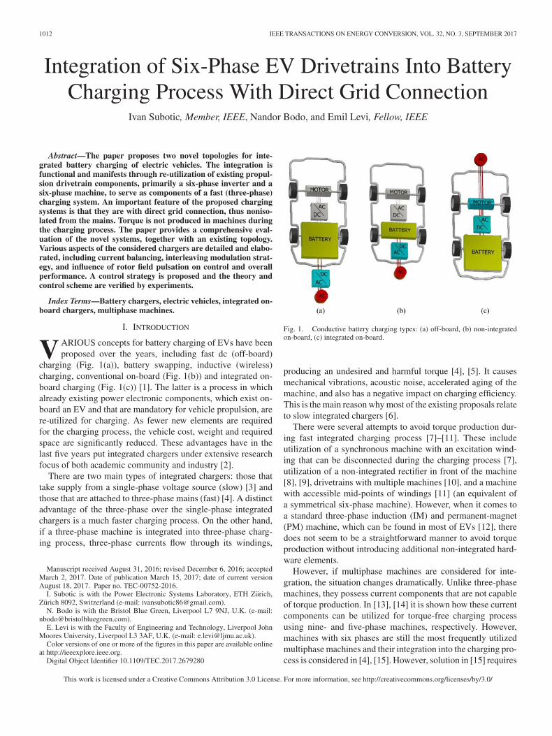
VARIOUS concepts for battery charging of EVs have beenproposed over the years, including fast dc (off-board)
charging (Fig. 1(a)), battery swapping, inductive (wireless)charging, conventional on-board (Fig. 1(b)) and integrated on-board charging (Fig. 1(c)) [1]. The latter is a process in whichalready existing power electronic components, which exist on-board an EV and that are mandatory for vehicle propulsion, arere-utilized for charging. As fewer new elements are requiredfor the charging process, the vehicle cost, weight and requiredspace are significantly reduced. These advantages have in thelast five years put integrated chargers under extensive researchfocus of both academic community and industry [2].
There are two main types of integrated chargers: those thattake supply from a single-phase voltage source (slow) [3] andthose that are attached to three-phase mains (fast) [4]. A distinctadvantage of the three-phase over the single-phase integratedchargers is a much faster charging process. On the other hand,if a three-phase machine is integrated into three-phase charg-ing process, three-phase currents flow through its windings,
Manuscript received August 31, 2016; revised December 6, 2016; acceptedMarch 2, 2017. Date of publication March 15, 2017; date of current versionAugust 18, 2017. Paper no. TEC-00752-2016.
I. Subotic is with the Power Electronic Systems Laboratory, ETH Zurich,Zurich 8092, Switzerland (e-mail: [email protected]).
N. Bodo is with the Bristol Blue Green, Liverpool L7 9NJ, U.K. (e-mail:[email protected]).
E. Levi is with the Faculty of Engineering and Technology, Liverpool JohnMoores University, Liverpool L3 3AF, U.K. (e-mail: [email protected]).
Color versions of one or more of the figures in this paper are available onlineat http://ieeexplore.ieee.org.
Digital Object Identifier 10.1109/TEC.2017.2679280
Fig. 1. Conductive battery charging types: (a) off-board, (b) non-integratedon-board, (c) integrated on-board.
producing an undesired and harmful torque [4], [5]. It causesmechanical vibrations, acoustic noise, accelerated aging of themachine, and also has a negative impact on charging efficiency.This is the main reason why most of the existing proposals relateto slow integrated chargers [6].
There were several attempts to avoid torque production dur-ing fast integrated charging process [7]–[11]. These includeutilization of a synchronous machine with an excitation wind-ing that can be disconnected during the charging process [7],utilization of a non-integrated rectifier in front of the machine[8], [9], drivetrains with multiple machines [10], and a machinewith accessible mid-points of windings [11] (an equivalent ofa symmetrical six-phase machine). However, when it comes toa standard three-phase induction (IM) and permanent-magnet(PM) machine, which can be found in most of EVs [12], theredoes not seem to be a straightforward manner to avoid torqueproduction without introducing additional non-integrated hard-ware elements.
However, if multiphase machines are considered for inte-gration, the situation changes dramatically. Unlike three-phasemachines, they possess current components that are not capableof torque production. In [13], [14] it is shown how these currentcomponents can be utilized for torque-free charging processusing nine- and five-phase machines, respectively. However,machines with six phases are still the most frequently utilizedmultiphase machines and their integration into the charging pro-cess is considered in [4], [15]. However, solution in [15] requires
This work is licensed under a Creative Commons Attribution 3.0 License. For more information, see http://creativecommons.org/licenses/by/3.0/
SUBOTIC et al.: INTEGRATION OF SIX-PHASE EV DRIVETRAINS INTO BATTERY CHARGING PROCESS WITH DIRECT GRID CONNECTION 1013
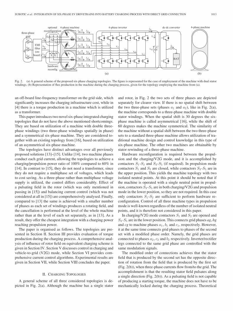
Fig. 2. (a) A general scheme of the proposed six-phase charging topologies. The figure is represented for the case of employment of the machine with dual statorwindings. (b) Representation of flux production in the machine during the charging process, given for the topology employing the machine from (a).
an off-board line-frequency transformer on the grid side, whichsignificantly increases the charging infrastructure cost, while in[4] there is a torque production in a machine which is utilizedas a transformer.
This paper introduces two novel six-phase integrated chargingtopologies that do not have the above mentioned shortcomings.They are based on utilization of a machine with double three-phase windings (two three-phase windings spatially in phase)and a symmetrical six-phase machine. They are considered to-gether with an existing topology from [16], based on utilizationof an asymmetrical six-phase machine.
The topologies have distinct advantages over all previouslyproposed solutions [13]–[15]. Unlike [14], two machine phasesconduct each grid current, allowing the topologies to achieve acharging/propulsion power ratio of 100% compared to 60% in[14]. In contrast to [15], they do not need a transformer, sincethey do not require a multiphase set of voltages, which leadsto cost saving. As a three-phase rather than multiphase voltagesupply is utilized, the control differs considerably. Effect ofa pulsating field in the rotor (which was only mentioned inpassing in [15]) and balancing current control (which was notconsidered at all in [15]) are comprehensively analysed. Finally,compared to [13] the same is achieved with a smaller numberof phases as each set of windings produces a rotating field, andthe cancellation is performed at the level of the whole machinerather than at the level of each set separately, as in [13]. As aresult, they offer the cheapest integration with a charging powerreaching propulsion power.
The paper is organised as follows. The topologies are pre-sented in Section II. Section III provides evaluation of torqueproduction during the charging process. A comprehensive anal-ysis of influence of rotor field on equivalent charging scheme isgiven in Section IV. Section V discusses control in charging andvehicle-to-grid (V2G) mode, while Section VI provides com-prehensive current control algorithms. Experimental results aregiven in Section VII, while Section VIII concludes the paper.
II. CHARGING TOPOLOGIES
A general scheme of all three considered topologies is de-picted in Fig. 2(a). Although the machine has a single stator
and rotor, in Fig. 2 the two sets of three phases are depictedseparately for clearer view. If there is no spatial shift betweenthe two three-phase sets (phases a1 and a2), like in Fig. 2(a),the machine corresponds to a three-phase machine with doublestator windings. When the spatial shift is 30 degrees the six-phase machine is called asymmetrical [16], while the shift of60 degrees makes the machine symmetrical. The similarity ofthe machine without a spatial shift between the two three-phasesets to a standard three-phase machine allows utilization of tra-ditional machine design and control knowledge in this type ofsix-phase machine. The other two machines are obtainable bystator rewinding of a three-phase machine.
Hardware reconfiguration is required between the propul-sion and the charging/V2G mode, and it is accomplished bycontactors S1-S2 and S3-S5 (if required). In propulsion modecontactors S1 and S2 are closed, while contactors S3-S5 are inthe upper position. This yields the machine topology with twoisolated neutral points. At this point it should be noted that ifthe machine is operated with a single neutral point in propul-sion, contactors S3-S5 are in both charging/V2G and propulsionmode in the lower position, so they are not required. In this caseonly contactors S1-S2 are sufficient to perform hardware re-configuration. Control of all three machine types in propulsionmode is well-known regardless of the number of isolated neutralpoints, and it is therefore not considered in this paper.
In charging/V2G mode contactors S1 and S2 are opened andS3-S5 are in the lower position. This connects grid phases ag, bgand cg to machine phases a1 , b1 and c1 , respectively. However,it at the same time connects grid phases to phases of the secondset with a modified phase order. Namely, the grid phases areconnected to phases a2 , c2 and b2 respectively. Inverter/rectifierlegs connected to the same grid phase are controlled with thesame modulation signals.
The modified order of connections achieves that the statorfield that is produced by the second set has the opposite direc-tion of rotation from the field that is produced by the first set(Fig. 2(b)), when three-phase currents flow from/to the grid. Theaccomplishment is that the resulting stator field pulsates alonga single direction (Fig. 2(b)). As a pulsating field is not capableof producing a starting torque, the machine does not have to bemechanically locked during the charging process. Theoretical

1014 IEEE TRANSACTIONS ON ENERGY CONVERSION, VOL. 32, NO. 3, SEPTEMBER 2017
assessment of torque production in all three charging topologiesis considered in the next section.
It should be noted that the industrial standard for EV batterychargers is the existence of an EMI (electro-magnetic inter-ference) filter towards the grid. However, the majority of theproposed integrated chargers are without the EMI filter as itwould interfere with the propulsion mode. In all the proposedtopologies in this paper, the EMI filter exists on-board the ve-hicle (Fig. 2(a)). Its interference with the propulsion mode isprevented by contactors S1 and S2 , which are the only manda-tory non-integrated elements for all topologies. The contactorssignificantly differ from switches that are required in converters(IGBTs and MOSFETs), both by functionality and cost. Thecontactors do not introduce operational losses as they are onlyused to change the mode of operation, from charging/V2G modeto propulsion and vice versa.
III. EVALUATION OF TORQUE PRODUCTION
Machine torque production evaluation is of paramount im-portance for integrated charging, since it should be avoided.However, its existence cannot be assessed by means of speedmeasurement. Namely, if a machine that is not locked does notrotate during the charging/V2G process, it does not imply thatit is not producing a very harmful torque. A torque can stillbe present, although incapable of surpassing friction. A conve-nient and reliable manner of gathering precise information ontorque existence is observation of machine currents in a decou-pled domain. In what follows, this method is elaborated andemployed to assess torque production in the three discussedtopologies.
Decoupling matrices of six-phase systems differ from theone for systems with three phases. Three-phase systems havethree currents, of which only two are independent (i.e., can haveany value), and the third phase current can be obtained fromthe first two (if there is no zero-sequence current). Therefore,there are only two degrees of freedom. However, the two actualcurrents are not orthogonal; thus a decoupling matrix has to beintroduced. It keeps the number of degrees of freedom the same,while making the current components mutually orthogonal.
On the other hand, six-phase systems have six phase currents,of which four or five are independent (i.e., can have any value)depending on whether there are two isolated or a single neutralpoint, respectively. Therefore, there are four or five degrees offreedom. Again, the currents are not mutually orthogonal. Forthat reason a decoupling matrix is introduced. It again keeps thenumber of degrees of freedom the same, but makes the compo-nents mutually orthogonal. As the result, the first two compo-nents (α and β components) are responsible for field and torqueproduction in the machine, while the remaining components (x,y, 0+ and 0−) are responsible for losses. Finally, each compo-nent pair can be represented in a single two-dimensional planewhose axes are the two corresponding orthogonal components.
For symmetrical six-phase systems decoupling matrix canbe obtained from its general multiphase form given in [17],while for the asymmetrical system it is given in [16].
Decoupling matrix of dual three-phase systems is governed with[18]:
C =1√3·
⎡⎢⎢⎢⎢⎢⎢⎢⎢⎢⎢⎢⎢⎢⎢⎢⎢⎢⎢⎣
1 cos(
2π
3
)cos
(4π
3
)1 cos
(2π
3
)cos
(4π
3
)
0 sin(
2π
3
)sin
(4π
3
)0 sin
(2π
3
)sin
(4π
3
)
1 cos(
4π
3
)cos
(2π
3
)−1 cos
(π
3
)cos
(5π
3
)
0 sin(
4π
3
)sin
(2π
3
)0 sin
(π
3
)sin
(5π
3
)
1 1 1 0 0 0
0 0 0 1 1 1
⎤⎥⎥⎥⎥⎥⎥⎥⎥⎥⎥⎥⎥⎥⎥⎥⎥⎥⎥⎦
(1)
Grid standards and regulations demand that all currents takenfrom or injected into the grid have to be sinusoidal and in phaseor phase opposition with grid phase voltages. Hence, currentsthat are taken from the grid have to be governed with:
ikg =√
2I cos(ωt − l2π/3) k = a, b, c l = 0, 1, 2(2)
Pure observation of Fig. 2(a) is sufficient to determine thecorrelations between machine and grid currents as:
ia1 = ia2 =iag
2; ib1 = ic2 =
ibg
2; ic1 = ib2 =
icg
2(3)
which is valid for all three topologies. The machines’ behaviouris uniquely determined by currents flowing through them (2)–(3). In order to assess torque production, these currents aretransformed into a decoupled domain. For the double three-phase topology this is achieved by substituting (2) into (3); (3)is further formulated as a 6x1 column matrix of phase currentsand then transformed with (1). For the other two topologies, in-stead of (1), the corresponding decoupling transformation ma-trices [16], [17] are used. The results are given in Table I. Thederivations are given in Appendix A.
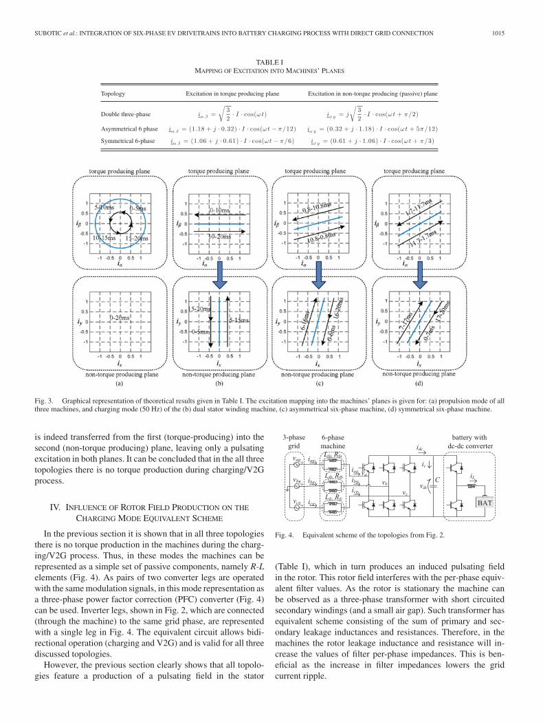
As six-phase systems are being transformed, the decoupledsystems have six components each, three more than systems withthree-phases. From Table I it can be seen that excitation utilizesfour of these components. These are α-β components whichexist in three-phase systems and are in charge of torque/fluxproduction, and additional two components denoted with x-y,which are incapable of producing a torque. Table I implies thata significant amount of excitation is transferred from the α-βinto x-y components. If α-β components are represented in theα-β plane, this transfer achieves that only a pulsating excitationremains in the α-β plane. The pulsating excitation produces apulsating field in the stator which is incapable of producing astarting torque.
Expressions given in Table I are verified utilizing Matlab andgraphically depicted in Fig. 3 in order to facilitate the analysis.Obviously, unlike in the propulsion mode, a part of the excitation
SUBOTIC et al.: INTEGRATION OF SIX-PHASE EV DRIVETRAINS INTO BATTERY CHARGING PROCESS WITH DIRECT GRID CONNECTION 1015
TABLE IMAPPING OF EXCITATION INTO MACHINES’ PLANES
Topology Excitation in torque producing plane Excitation in non-torque producing (passive) plane
Double three-phase iα β =√
32· I · cos(ωt) ix y = j
√32· I · cos(ωt + π/2)
Asymmetrical 6 phase iα β = (1.18 + j · 0.32) · I · cos(ωt − π/12) ix y = (0.32 + j · 1.18) · I · cos(ωt + 5π/12)
Symmetrical 6-phase iα β = (1.06 + j · 0.61) · I · cos(ωt − π/6) ix y = (0.61 + j · 1.06) · I · cos(ωt + π/3)
Fig. 3. Graphical representation of theoretical results given in Table I. The excitation mapping into the machines’ planes is given for: (a) propulsion mode of allthree machines, and charging mode (50 Hz) of the (b) dual stator winding machine, (c) asymmetrical six-phase machine, (d) symmetrical six-phase machine.
is indeed transferred from the first (torque-producing) into thesecond (non-torque producing) plane, leaving only a pulsatingexcitation in both planes. It can be concluded that in the all threetopologies there is no torque production during charging/V2Gprocess.
IV. INFLUENCE OF ROTOR FIELD PRODUCTION ON THE
CHARGING MODE EQUIVALENT SCHEME
In the previous section it is shown that in all three topologiesthere is no torque production in the machines during the charg-ing/V2G process. Thus, in these modes the machines can berepresented as a simple set of passive components, namely R-Lelements (Fig. 4). As pairs of two converter legs are operatedwith the same modulation signals, in this mode representation asa three-phase power factor correction (PFC) converter (Fig. 4)can be used. Inverter legs, shown in Fig. 2, which are connected(through the machine) to the same grid phase, are representedwith a single leg in Fig. 4. The equivalent circuit allows bidi-rectional operation (charging and V2G) and is valid for all threediscussed topologies.
However, the previous section clearly shows that all topolo-gies feature a production of a pulsating field in the stator
Fig. 4. Equivalent scheme of the topologies from Fig. 2.
(Table I), which in turn produces an induced pulsating fieldin the rotor. This rotor field interferes with the per-phase equiv-alent filter values. As the rotor is stationary the machine canbe observed as a three-phase transformer with short circuitedsecondary windings (and a small air gap). Such transformer hasequivalent scheme consisting of the sum of primary and sec-ondary leakage inductances and resistances. Therefore, in themachines the rotor leakage inductance and resistance will in-crease the values of filter per-phase impedances. This is ben-eficial as the increase in filter impedances lowers the gridcurrent ripple.
1016 IEEE TRANSACTIONS ON ENERGY CONVERSION, VOL. 32, NO. 3, SEPTEMBER 2017
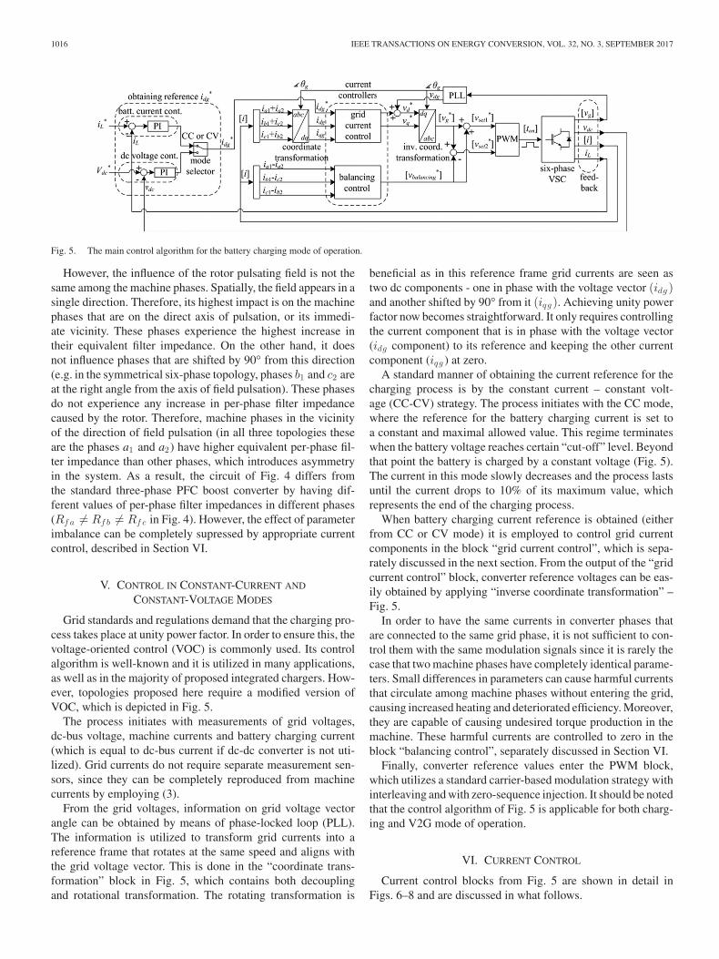
Fig. 5. The main control algorithm for the battery charging mode of operation.
However, the influence of the rotor pulsating field is not thesame among the machine phases. Spatially, the field appears in asingle direction. Therefore, its highest impact is on the machinephases that are on the direct axis of pulsation, or its immedi-ate vicinity. These phases experience the highest increase intheir equivalent filter impedance. On the other hand, it doesnot influence phases that are shifted by 90° from this direction(e.g. in the symmetrical six-phase topology, phases b1 and c2 areat the right angle from the axis of field pulsation). These phasesdo not experience any increase in per-phase filter impedancecaused by the rotor. Therefore, machine phases in the vicinityof the direction of field pulsation (in all three topologies theseare the phases a1 and a2) have higher equivalent per-phase fil-ter impedance than other phases, which introduces asymmetryin the system. As a result, the circuit of Fig. 4 differs fromthe standard three-phase PFC boost converter by having dif-ferent values of per-phase filter impedances in different phases(Rf a �= Rf b �= Rf c in Fig. 4). However, the effect of parameterimbalance can be completely supressed by appropriate currentcontrol, described in Section VI.
V. CONTROL IN CONSTANT-CURRENT AND
CONSTANT-VOLTAGE MODES
Grid standards and regulations demand that the charging pro-cess takes place at unity power factor. In order to ensure this, thevoltage-oriented control (VOC) is commonly used. Its controlalgorithm is well-known and it is utilized in many applications,as well as in the majority of proposed integrated chargers. How-ever, topologies proposed here require a modified version ofVOC, which is depicted in Fig. 5.
The process initiates with measurements of grid voltages,dc-bus voltage, machine currents and battery charging current(which is equal to dc-bus current if dc-dc converter is not uti-lized). Grid currents do not require separate measurement sen-sors, since they can be completely reproduced from machinecurrents by employing (3).
From the grid voltages, information on grid voltage vectorangle can be obtained by means of phase-locked loop (PLL).The information is utilized to transform grid currents into areference frame that rotates at the same speed and aligns withthe grid voltage vector. This is done in the “coordinate trans-formation” block in Fig. 5, which contains both decouplingand rotational transformation. The rotating transformation is
beneficial as in this reference frame grid currents are seen astwo dc components - one in phase with the voltage vector (idg )and another shifted by 90° from it (iqg ). Achieving unity powerfactor now becomes straightforward. It only requires controllingthe current component that is in phase with the voltage vector(idg component) to its reference and keeping the other currentcomponent (iqg ) at zero.
A standard manner of obtaining the current reference for thecharging process is by the constant current – constant volt-age (CC-CV) strategy. The process initiates with the CC mode,where the reference for the battery charging current is set toa constant and maximal allowed value. This regime terminateswhen the battery voltage reaches certain “cut-off” level. Beyondthat point the battery is charged by a constant voltage (Fig. 5).The current in this mode slowly decreases and the process lastsuntil the current drops to 10% of its maximum value, whichrepresents the end of the charging process.
When battery charging current reference is obtained (eitherfrom CC or CV mode) it is employed to control grid currentcomponents in the block “grid current control”, which is sepa-rately discussed in the next section. From the output of the “gridcurrent control” block, converter reference voltages can be eas-ily obtained by applying “inverse coordinate transformation” –Fig. 5.
In order to have the same currents in converter phases thatare connected to the same grid phase, it is not sufficient to con-trol them with the same modulation signals since it is rarely thecase that two machine phases have completely identical parame-ters. Small differences in parameters can cause harmful currentsthat circulate among machine phases without entering the grid,causing increased heating and deteriorated efficiency. Moreover,they are capable of causing undesired torque production in themachine. These harmful currents are controlled to zero in theblock “balancing control”, separately discussed in Section VI.
Finally, converter reference values enter the PWM block,which utilizes a standard carrier-based modulation strategy withinterleaving and with zero-sequence injection. It should be notedthat the control algorithm of Fig. 5 is applicable for both charg-ing and V2G mode of operation.
VI. CURRENT CONTROL
Current control blocks from Fig. 5 are shown in detail inFigs. 6–8 and are discussed in what follows.

SUBOTIC et al.: INTEGRATION OF SIX-PHASE EV DRIVETRAINS INTO BATTERY CHARGING PROCESS WITH DIRECT GRID CONNECTION 1017
Fig. 6. “Grid current control” block from Fig 5.
Fig. 7. “Resonant VPI controller” block from Fig. 6.
Fig. 8. “Balancing control” block from Fig. 5.
A. Fundamental Grid Current Control
Current components idg and iqg are dc quantities. Thus,they can be easily controlled to their references (i∗dg and 0,respectively) with PI controllers shown in Fig. 6. This is suf-ficient for control of current fundamental in symmetrical sys-tems (where Rf a = Rf b = Rf c ). However, as already notedin Section IV, filter per-phase parameters are not the same(Rf a �= Rf b �= Rf c ), thus the system is not symmetrical. Thisresults in a current component that rotates at synchronous speedin anti-synchronous direction (observed from the stationary ref-erence frame). This current component appears as the secondharmonic in the synchronous reference frame. It can be com-pletely zeroed by a pair of resonant vector proportional inte-gral (VPI) current controllers tuned at the second harmonic –Fig. 6. The scheme of a resonant VPI current controller ofFig. 6 is depicted in Fig. 7.
Parameters of the current controllers have been determinedby “modulus optimum” method, based on the closed loop modelof the system.
B. Harmonic Compensation
Inverter dead-time is the main source of harmonics in thesystem. These are primarily −5th, 7th, −11th and 13th (as seenfrom the stationary reference frame). From the synchronous ref-erence frame, these harmonics are seen as −6th, 6th, −12th and12th. They can conveniently be zeroed by two pairs of resonantVPI current controllers tuned at 6th and 12th harmonic. This issufficient for a proper control of symmetrical systems and givessatisfactory results for systems where parameter asymmetry isnot high. However, in systems with a pronounced parameterasymmetry (such as those in this paper) it cannot completelyzero the harmonics. Namely, in asymmetrical systems harmon-ics also have additional components that rotate in the oppositedirection than in symmetrical systems. Thus, although with verysmall values, the 5th, −7th, 11th and −13th (as seen from thestationary reference frame) harmonics are introduced. From thesynchronous reference frame these harmonics are seen as the4th, −8th, 10th and −14th. Therefore, the corresponding res-onant VPI current controllers have to be added to the system.The scheme shown in Fig. 6 is capable of complete removal ofharmonics, as will be verified in Section VII.
C. Current Balancing
Differences between each two machine phase currents con-nected to the same grid phase are fed into block “balancingcontrol”, which is shown separately in Fig. 8. As already notedthese current components are harmful and can even cause torqueproduction in the machine. They can be zeroed in the stationaryreference frame by three resonant VPI controllers, as shown inFig. 8, and verified in Section VII-F.
D. Modulation Strategy With Interleaving
An advantage of the proposed topologies is that the mod-ulation strategy with interleaving can be employed in or-der to decrease grid current switching ripple and facilitate
1018 IEEE TRANSACTIONS ON ENERGY CONVERSION, VOL. 32, NO. 3, SEPTEMBER 2017
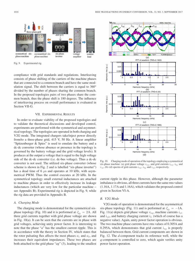
Fig. 9. Experimental rig.
compliance with grid standards and regulations. Interleavingconsists of phase shifting of the carriers of the machine phasesthat are connected to a common branch and have the same mod-ulation signal. The shift between the carriers is equal to 360°divided by the number of phases sharing the common branch.In the proposed topologies pairs of two phases share the com-mon branch, thus the phase shift is 180 degrees. The influenceof interleaving process on overall performance is evaluated inSection VII-G.
VII. EXPERIMENTAL RESULTS
In order to evaluate viability of the proposed topologies andto validate the theoretical discussions and developed control,experiments are performed with the symmetrical and asymmet-rical topology. The topologies are operated in both charging andV2G mode. The integrated chargers take/inject power directlyfrom/to a three-phase grid, 415 V, 50 Hz. A linear amplifier“Spitzenberger & Spies” is used to emulate the battery and adc-dc converter (whose absence or presence in the topology isgoverned by the battery voltage and the grid voltage levels). Itproduces at the output a voltage that is equal to the high voltageside of the dc-dc converter (i.e. dc-bus voltage). Thus a dc-dcconverter is not used. The utilized six-phase converter (whosescheme is shown in Fig. 2 and is labelled “six-phase inverter”)has a dead time of 6 μs and operates at 10 kHz, with asym-metrical PWM. Thus the control executes at 20 kHz. In thesymmetrical topology small external inductances are attachedto machine phases in order to effectively increase its leakageinductances (which are very low for the particular machine –see Appendix B). Experimental rig is depicted in Fig. 9, whilethe rig data are provided in Appendix B.
A. Charging Mode
The charging mode is demonstrated for the symmetrical six-phase topology (Fig. 10) and it is performed at i∗dg = 2A. Allthree grid currents together with grid phase voltage are shownin Fig. 10(a). It can be seen that the currents are in phase withgrid voltages, achieving unity power factor. It is interesting tonote that the phase “a” has the smallest current ripple. This isin accordance with the theory in Section IV, which states thatthe rotor pulsating flux affects the most phases a1 and a2 , andincreases their equivalent impedances. These two phases areboth attached to the grid phase “ag” (3), leading to the smallest
Fig. 10. Charging mode of operation of the topology employing a symmetricalsix-phase machine: (a) grid phase voltage vag , and grid currents ia g , ibg andicg , (b)–(d) spectra of grid currents ia g , ibg and icg , respectively.
current ripple in this phase. However, although the parameterimbalance is obvious, all three currents have the same rms values(1.16A, 1.17A and 1.16A), which validates the proposed controlgiven in Section VI-A.
B. V2G Mode
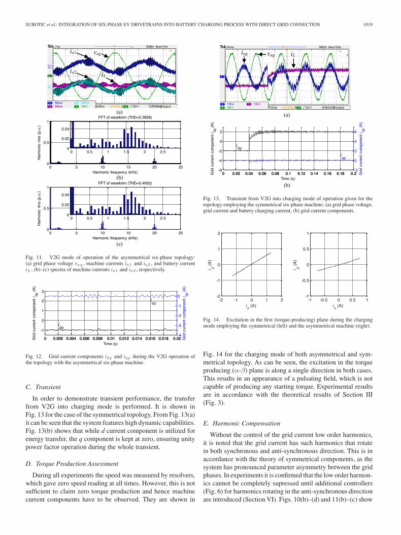
V2G mode of operation is demonstrated for the asymmetricalsix-phase topology (Fig. 11) and is performed at i∗dg = −1A.Fig. 11(a) depicts grid phase voltage vag , machine currents ia1and ia2 , and battery charging current iL (which of course has anegative value). Again, unity power factor operation is obvious.The two machine phase currents have rms values of 0.305A and0.295A, which demonstrates that grid current iag is properlybalanced between them. Grid current components are shown inFig. 12. The d-component tracks its reference well, while theq-component is controlled to zero, which again verifies unitypower factor operation.
SUBOTIC et al.: INTEGRATION OF SIX-PHASE EV DRIVETRAINS INTO BATTERY CHARGING PROCESS WITH DIRECT GRID CONNECTION 1019
Fig. 11. V2G mode of operation of the asymmetrical six-phase topology:(a) grid phase voltage vag , machine currents ia1 and ia2 , and battery currentiL , (b)–(c) spectra of machine currents ia1 and ia2 , respectively.
Fig. 12. Grid current components idg and iq g during the V2G operation ofthe topology with the asymmetrical six-phase machine.
C. Transient
In order to demonstrate transient performance, the transferfrom V2G into charging mode is performed. It is shown inFig. 13 for the case of the symmetrical topology. From Fig. 13(a)it can be seen that the system features high dynamic capabilities.Fig. 13(b) shows that while d current component is utilized forenergy transfer, the q component is kept at zero, ensuring unitypower factor operation during the whole transient.
D. Torque Production Assessment
During all experiments the speed was measured by resolvers,which gave zero speed reading at all times. However, this is notsufficient to claim zero torque production and hence machinecurrent components have to be observed. They are shown in
Fig. 13. Transient from V2G into charging mode of operation given for thetopology employing the symmetrical six-phase machine: (a) grid phase voltage,grid current and battery charging current, (b) grid current components.
Fig. 14. Excitation in the first (torque-producing) plane during the chargingmode employing the symmetrical (left) and the asymmetrical machine (right).
Fig. 14 for the charging mode of both asymmetrical and sym-metrical topology. As can be seen, the excitation in the torqueproducing (α-β) plane is along a single direction in both cases.This results in an appearance of a pulsating field, which is notcapable of producing any starting torque. Experimental resultsare in accordance with the theoretical results of Section III(Fig. 3).
E. Harmonic Compensation
Without the control of the grid current low order harmonics,it is noted that the grid current has such harmonics that rotatein both synchronous and anti-synchronous direction. This is inaccordance with the theory of symmetrical components, as thesystem has pronounced parameter asymmetry between the gridphases. In experiments it is confirmed that the low order harmon-ics cannot be completely supressed until additional controllers(Fig. 6) for harmonics rotating in the anti-synchronous directionare introduced (Section VI). Figs. 10(b)–(d) and 11(b)–(c) show
1020 IEEE TRANSACTIONS ON ENERGY CONVERSION, VOL. 32, NO. 3, SEPTEMBER 2017
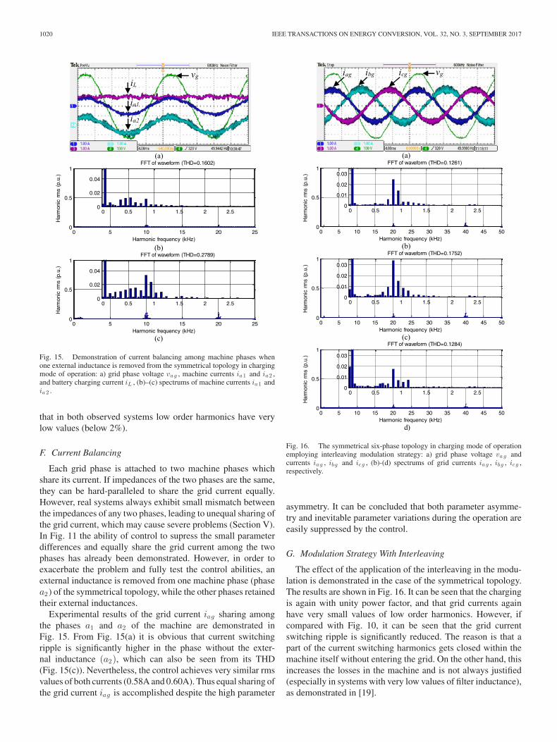
Fig. 15. Demonstration of current balancing among machine phases whenone external inductance is removed from the symmetrical topology in chargingmode of operation: a) grid phase voltage vag , machine currents ia1 and ia2 ,and battery charging current iL , (b)–(c) spectrums of machine currents ia1 andia2 .
that in both observed systems low order harmonics have verylow values (below 2%).
F. Current Balancing
Each grid phase is attached to two machine phases whichshare its current. If impedances of the two phases are the same,they can be hard-paralleled to share the grid current equally.However, real systems always exhibit small mismatch betweenthe impedances of any two phases, leading to unequal sharing ofthe grid current, which may cause severe problems (Section V).In Fig. 11 the ability of control to supress the small parameterdifferences and equally share the grid current among the twophases has already been demonstrated. However, in order toexacerbate the problem and fully test the control abilities, anexternal inductance is removed from one machine phase (phasea2) of the symmetrical topology, while the other phases retainedtheir external inductances.
Experimental results of the grid current iag sharing amongthe phases a1 and a2 of the machine are demonstrated inFig. 15. From Fig. 15(a) it is obvious that current switchingripple is significantly higher in the phase without the exter-nal inductance (a2), which can also be seen from its THD(Fig. 15(c)). Nevertheless, the control achieves very similar rmsvalues of both currents (0.58A and 0.60A). Thus equal sharing ofthe grid current iag is accomplished despite the high parameter
Fig. 16. The symmetrical six-phase topology in charging mode of operationemploying interleaving modulation strategy: a) grid phase voltage vag andcurrents ia g , ibg and icg , (b)-(d) spectrums of grid currents ia g , ibg , icg ,respectively.
asymmetry. It can be concluded that both parameter asymme-try and inevitable parameter variations during the operation areeasily suppressed by the control.
G. Modulation Strategy With Interleaving
The effect of the application of the interleaving in the modu-lation is demonstrated in the case of the symmetrical topology.The results are shown in Fig. 16. It can be seen that the chargingis again with unity power factor, and that grid currents againhave very small values of low order harmonics. However, ifcompared with Fig. 10, it can be seen that the grid currentswitching ripple is significantly reduced. The reason is that apart of the current switching harmonics gets closed within themachine itself without entering the grid. On the other hand, thisincreases the losses in the machine and is not always justified(especially in systems with very low values of filter inductance),as demonstrated in [19].
SUBOTIC et al.: INTEGRATION OF SIX-PHASE EV DRIVETRAINS INTO BATTERY CHARGING PROCESS WITH DIRECT GRID CONNECTION 1021
VIII. CONCLUSION
The paper introduces novel charging topologies that integratesix-phase machines into charging process with direct grid con-nection. The topologies do not require a line-frequency trans-former at the front, which allows substantial cost savings. In-fluence of a pulsating field production in all the topologies isanalysed, and it is demonstrated that a torque is not producedduring the charging/V2G operation. A control capable of fullysupressing the parameter asymmetry, which is introduced bythe pulsating field, as well as supressing parameter unbalancebetween machine phases is proposed. A comprehensive exper-imental investigation has been conducted and the results fullysupport theoretical developments.
APPENDIX A
Derivation procedure for all equations in Table I is similar.Therefore, only a general illustration is provided here for thecase of the symmetrical six-phase topology.
Decoupling real Clarke’s matrix for the symmetrical six-phase machines can be found in [17]. It is beneficial to representit in a space vector form:
iαβ = iα + jiβ =√
2/6(ia1 + aia2 + a2ib1 + a3ib2
+ a4ic1 + a5ic2)
(4)
ixy = ix + jiy =√
2/6(ia1 + a2ia2 + a4ib1
+ a6ib2 + a8ic1 + a10ic2)
(5)
where a = exp(jδ) = cos δ + j sin δ and δ = 2π/6.Grid currents are given with (2), while the correlation between
machine and grid currents is governed with (3). Substitution of(2) and (3) into (4) leads to the following expression:
iαβ =
√26· I ·
√2
2
{12
(ejωt + e−jω t
) (1 + ejδ
)
+12
(ej (ωt− 2 π
3 ) + e−j (ωt− 2 π3 )
) (ej2δ + ej5δ
)
+12
(ej (ωt− 4 π
3 ) + e−j (ωt− 4 π3 )
) (ej3δ + ej4δ
)}(6)
Components that are multiplied by ejωt and those multipliedby e−jω t can be separated, after which the following expressionsare obtained:
iαβ =I
2√
6
{ejωt ·
[(1 + ejδ
)+ e−j 2 π
3(ej2δ + ej5δ
)
+ e−j 4 π3
(ej3δ + ej4δ
)]
+ e−jω t ·[(
1 + ejδ)
+ ej 2 π3
(ej2δ + ej5δ
)
+ ej 4 π3
(ej3δ + ej4δ
)]}(7)
iαβ =I
2√
6
[ejωt · (3 − j · 0) + e−jω t · (1.5 + j · 2.598)
]
(8)
iαβ =I
2√
6
[ejωt · 3 · ej0 + e−jω t · 3 · ej ( π
3 )]
(9)
iαβ =I
2√
6· 3 · ej ( π
6 )[ejωt · e−j ( π
6 ) + e−jω t · ej ( π6 )
](10)
iαβ =I
2√
6· 3 · ej ( π
6 )[ej (ωt− π
6 ) + e−j (ωt− π6 )
](11)
iαβ =I√6· 3 · ej ( π
6 ) · cos(ωt − π
6
)(12)
iαβ = (1.06 + j · 0.61) · I · cos(ωt − π
6
)(13)
The result clearly represents the expression given inTable I for the symmetrical six-phase system. The excitationin the second (x-y plane) can be obtained in the same manner;the same applies for the remaining two topologies.
APPENDIX B: EXPERIMENTAL RIG DATA
Symmetrical six-phase induction machine: The parame-ters are Rs = 3.6 Ω, Rr = 1.8 Ω, Lm = 205 mH, Lγs =8.1 mH, Lγr = 11.5 mH. The machine has three pole pairs,50 Hz, 110 V (phase-to-neutral), 1.1 kW, 900 rpm.
Asymmetrical six-phase induction machine: The parametersare Rs = 12.5 Ω, Rr = 6 Ω, Lm = 590 mH, Lγs = 61.5 mH,Lγr = 11 mH. A six-pole machine is obtained by rewinding a380 V, 50 Hz, 1.1 kW three-phase machine.
Small external inductances: 10 mH per grid phase. They areutilized only with the symmetrical six-phase topology.
Dc source/sink: “Spitzenberger & Spies” – two DM2500/PAS systems connected in series. Power sinking up to4 kW is enabled by an additional resistive load RL 4000, whichis shown in Fig. 9 and is labelled as “resistor load”.
Controller: dSPACE DS1006 processor board. DS2004 high-speed A/D board and DS5101 Digital Waveform Output Boardare used for the A/D conversion of measured signals and PWMsignal generation. Incremental Encoder Interface Board DS3002is used to validate that machines do not move during the charg-ing/V2G process.
Converter: Custom made eight-phase inverter with EUPECFS50R12KE3 IGBTs. Using the heat-sink data, it is estimatedthat the rated continuous output rms current is 14A, which givesfor a 240 V rms phase voltage for six phases of inverter contin-uous rating of approximately 20 kVA.
REFERENCES
[1] D. G. Woo, D. M. Joo, and B. K. Lee, “On the feasibility of integratedbattery charger utilizing traction motor and inverter in plug-in hybridelectric vehicles,” IEEE Trans. Power Electron., vol. 30, no. 12, pp. 7270–7281, Dec. 2015.
[2] N. Sakr, D. Sadarnac, and A. Gascher, “A review of on-board integratedchargers for electric vehicles,” in Proc. Eur. Conf. Power Electron. Appl.,Lappeenranta, Finland, 2014, pp. 1–10, doi: 10.1109/EPE.2014.6910865.
[3] I. Subotic and E. Levi, “A review of single-phase on-board integratedbattery charging topologies for electric vehicles,” in Proc. IEEE WorkshopElect. Mach. Des., Control Diagnosis, Torino, Italy, 2015, pp. 136–145 .
[4] S. Haghbin, S. Lundmark, M. Alakula, and O. Carlson, “Grid-connectedintegrated battery chargers in vehicle applications: Review and new solu-tion,” IEEE Trans. Ind. Electron., vol. 60, no. 2, pp. 459–473, Feb. 2013.
1022 IEEE TRANSACTIONS ON ENERGY CONVERSION, VOL. 32, NO. 3, SEPTEMBER 2017
[5] X. Lu, K. L. V. Iyer, K. Mukherjee, and N. C. Kar, “Investigation of inte-grated charging and discharging incorporating interior permanent magnetmachine with damper bars for electric vehicles,” IEEE Trans. EnergyConvers., vol. 31, no. 1, pp. 260–269, Mar. 2016.
[6] M. Yilmaz and P. T. Krein, “Review of integrated charging methods forplug-in electric and hybrid vehicles,” in Proc. IEEE Int. Conf. Veh. Elec-tron. Safety, Istanbul, Turkey, 2012, pp. 346–351.
[7] P. Dupuy, “Electric traction chain for an automobile,” U.S. Patent US2011/0187185 A1, Aug. 2011.
[8] S. Loudot, B. Briane, O. Ploix, and A. Villeneuve, “Fast charging devicefor an electric vehicle,” U.S. Patent US 8 847 555 B2, Sep. 2014.
[9] J. Hong, H. Lee, and K. Nam, “Charging method for the secondary batteryin dual-inverter drive systems for electric vehicles,” IEEE Trans. PowerElectron., vol. 30, no. 2, pp. 909–921, Feb. 2015.
[10] G. J. Su, “Electric vehicle system for charging and supplying electricalpower,” U.S. Patent US 7 733 039 B2, Jun. 2010.
[11] L. De Sousa and B. Bouchez, “Combined electric device for powering andcharging,” U.S. Patent US 2011/0221363 A1, Sep. 2011.
[12] J. D. Santiago et al., “Electrical motor drivelines in commercial all-electricvehicles: A review,” IEEE Trans. Veh. Technol., vol. 61, no. 2, pp. 475–484,Feb. 2012.
[13] I. Subotic, N. Bodo, E. Levi, and M. Jones, “On-board integrated batterycharger for EVs using an asymmetrical nine-phase machine,” IEEE Trans.Ind. Electron., vol. 62, no. 5, pp. 3285–3295, May 2015.
[14] I. Subotic, N. Bodo, and E. Levi, “An EV drive-train with integratedfast charging capability,” IEEE Trans. Power Electron., vol. 31, no. 2,pp. 1461–1471, Feb. 2016.
[15] I. Subotic, N. Bodo, E. Levi, M. Jones, and V. Levi, “Isolated chargersfor EVs incorporating six-phase machines,” IEEE Trans. Ind. Electron.,vol. 63, no. 1, pp. 653–664, Jan. 2016.
[16] I. Subotic, E. Levi, and N. Bodo, “A fast on-board integrated batterycharger for EVs using an asymmetrical six-phase machine,” in Proc.Veh. Power Propulsion Conf., Coimbra, Portugal, 2014, pp. 1–6, doi:10.1109/VPPC.2014.7006996.
[17] E. Levi, R. Bojoi, F. Profumo, H. A. Toliyat, and S. Williamson, “Mul-tiphase induction motor drives—A technology status review,” IET Elect.Power Appl., vol. 1, no. 4, pp. 489–516, 2007.
[18] D. Hadiouche, H. Razik, and A. Rezzoug, “Modelling of a double-starinduction motor with an arbitrary shift angle between its three phasewindings,” in Proc. Int. Conf. Power Electron. Motion Control, Kosice,Slovakia, 2000, pp. 125–130.
[19] N. Bodo, E. Levi, I. Subotic, J. Espina, L. Empringham, and M. Johnson,“Efficiency evaluation of fully integrated on-board EV battery chargerswith nine-phase machines,” IEEE Trans. Energy Convers., vol. 32, no. 1,pp. 257–266, Mar. 2017.
Ivan Subotic (S’12–M’16) received the Dipl.Ing. andM.Sc. degrees in electrical engineering from the Uni-versity of Belgrade, Belgrade, Serbia, in 2010 and2011, respectively, and the Ph.D. degree from theLiverpool John Moores University, Liverpool, U.K.,in 2015. He is currently with the ETH Zurich, as aPostdoctoral Research Associate. His main researchinterests include power electronics, electric vehicles,and control of multiphase drive systems.
Nandor Bodo received the Master’s degree in 2009in power electronics from the University of Novi Sad,Faculty of Technical Sciences, Novi Sad, Serbia, andthe Ph.D. degree in electrical engineering in 2013from Liverpool John Moores University, Liverpool,U.K. From September 2013 until March 2016, hewas with the Liverpool John Moores University, as aPostdoctoral Research Associate. He is now with theBristol Blue Green, Liverpool.
Emil Levi (S’89–M’92–SM’99–F’09) received theM.Sc. and Ph.D. degrees in electrical engineer-ing from the University of Belgrade, Belgrade, Yu-goslavia, in 1986 and 1990, respectively. He joinedLiverpool John Moores University, U.K. in May1992. Since September 2000, he is currently a Pro-fessor of electric machines and drives. He was aCo-Editor-in-Chief of the IEEE TRANSACTIONS ON
INDUSTRIAL ELECTRONICS in the 2009–2013 periodand is currently the Editor-in-Chief of the IET Elec-tric Power Applications and an Editor of the IEEE
TRANSACTIONS ON ENERGY CONVERSION. He received the Cyril Veinott Awardof the IEEE Power and Energy Society for 2009 and the Best Paper awardof the IEEE TRANSACTIONS ON INDUSTRIAL ELECTRONICS for 2008. In 2014,he received the “Outstanding Achievement Award” from the European PowerElectronics Association.