otdc800-1600 installation instruction · 2018-05-09 · otdc800-1600 installation instruction...
TRANSCRIPT
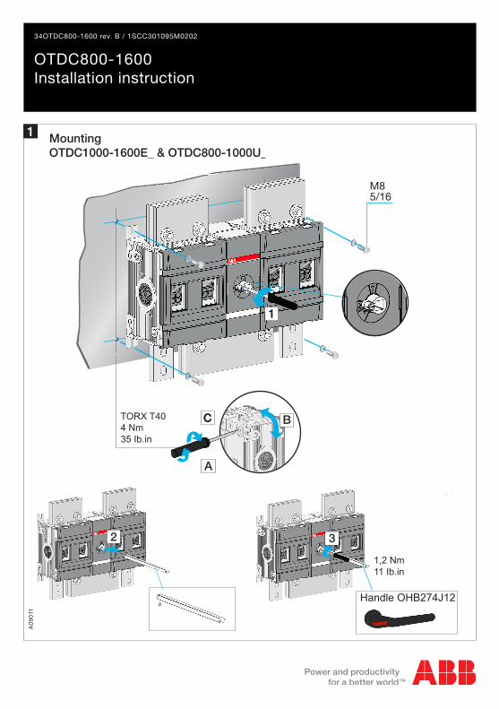
1,2 Nm11 Ib.in
Handle OHB274J12
M85/16
00
3
TORX T404 Nm35 Ib.in
A
C B
1
2
OTDC800-1600Installation instruction
34OTDC800-1600 rev. B / 1SCC301095M0202
MountingOTDC1000-1600E_ & OTDC800-1000U_
A09
011
1

OTDC1000E_
OZXA1200
Copper bars2 pcs 50 x 8 mm
Copper bars2 pcs 60 x 5 mm
Copper bars2 pcs 50 x 10 mm
Copper bar max width 60 mm
OTDC1250E_
OTDC800U_OTDC1000U_
OTDC1600E_
167
127
170
100
Barriers 68912 or OTS_ shrouds must be used on all OTDC 1000E...1600E andOTDC 800U...1000U_.
Type for package of 6 barriers is OTB1600/S.
Circuits
6a, 6b
6m
2ConnectionsOZX_
3Phase barriersOTB_
A09
016
A09
011
2
3

4A
0901
4
Minimum enclosure size of equivalent volume
Current A
Height [mm/in] 800 / 31.52
Width [mm/in] 600 / 23.64
Depth [mm/in] 300 / 11.82
Clearances per UL98Minimum distance to metal enclosure walls
Clearances and cabeling
A B D C
50 mm 50 mm 55 mm According to the
UL98 standard
OTDC800-1600C
C
A B D
4

5
Inpu
t(-
) +
Out
put
(-) +
M12 50...75 Nm443-664 lb.in
OTDC KIT 1250B11
OTDC KIT 1250B101
OTDC800US22_OTDC1000US22_
Circuit 6m, 1000 VDC
Connection kitsOTB_
A09
022
5
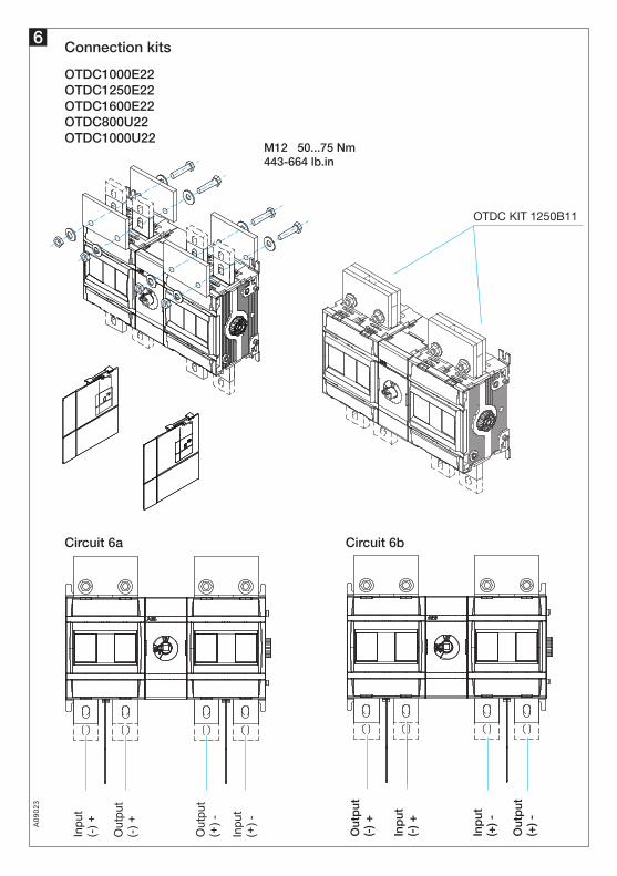
6Connection kits
Inpu
t(-
) +
OTDC KIT 1250B11
Out
put
(-) + Out
put
(+) -
Inpu
t(+
) -
Out
put
(-) +
Inp
ut(-
) +
Inp
ut(+
) -
Out
put
(+) -
Circuit 6a Circuit 6b
A09
023
6
OTDC1000E22OTDC1250E22OTDC1600E22OTDC800U22 OTDC1000U22
M12 50...75 Nm443-664 lb.in

7
OTDC1000U_ The rated current is limited to max. 980 A when shrouds are used.
OTDC1000US_ The rated current is limited to max. 920 A when shrouds are used.
Shrouds
OTDC800US22OTDC1000US22
M12 50...75 Nm 443-664 lb.in
Circuit 6ab, 1000 VDC Circuit 6m, 1000 VDC
Shrouds
A09
024
Shrouds
7
OTDC1000E22OTDC1250E22OTDC1600E22OTDC800U22OTDC1000U22
Shroud

OTDC800US22OTDC1000US22
8Labels
A09
013
LINE1
LOAD2
1
1
2
2
1
1 2
2
3
3
8

OTS1600 1LGT
OTS1600 1SGT
M12
443-664 lb.in
50...75 Nm
M
M
2
1
2
1
9Terminal shroudsOTS_
OTDC1000U22 The rated current is limited to max. 980 A when shrouds are used.
OTDC1000US22 The rated current is limited to max. 920 A when shrouds are used.
A09
015
9

10Auxiliary contact wiringOA_
A09
021
REMOVE
OR
NO: OA1G10NC: OA3G01
Test contact
Test indication contact
TEST IND.TEST IND.
Early operation
test contact
1 2
3 4
3 4
MAX 2 MAX 2 MAX 2
MAX 2 MAX 2 MAX 2
10
B
C
0
Main contact
Test contact (NO)
Test indication contact (NO)
Test contact (NC)
Test indication contact (NC)
1 0 Test 0
A
10

1
2
3
3
4
11
12
Additional auxiliary contacts
Auxiliary contact wiring
A09
017
A09
020
1...8 pcsOA1G10 (NO)OA3G01 (NC)
CLICK!
2
1
OEA28
0,4 Nm3.5 lb.in
0,4 Nm3.5 lb.in
3
4
5 6
0
Main contact
Test contact (NO)
Test contact (NC)
1 0 Test 0
11
12

OTZT4_
CLICK!
LOCKING
1,2 Nm11 lb.in
Handle OHB274J12
NOTE:min. 92 mm 3.6 in
OXP12x_
1 A
BC D
2
4 B
5
4 Nm 35 lb.inTorx 20
3
A
B
Ø8 mm 0.32 in
Flat connection 6,3-0,8 (DIN46244)
The cable is not included in the delivery
A
13Electornic interlockingOTV
A09
019
13

OTV1000EK
Note: Use protection against direct contact.
For example:
Ø5...Ø10 mm
27410.7990
3.54
1064.18
150.59M
0035
4
mmin
2
1,2 Nm11 lb.in
4
3
12
14Direct handle
A09
018
14

141615MOUNTING
15M
0049
2/O
TD
C80
0-12
50_2
2 C
OTDC800-1000US22 OTDC1000-1250E22 OTDC800-1000U22OTDC1600E22
414,516.32
823.23
1224.80
M85/16
1164.57
2068.11
1897.44
803.15
501.97
37214.65
30612.06
27410.79
702.76803.15
542.13
min 40min 2.13
120.47
220.87
80.31
80.31
150.59
251...360 (OXP12x280)9.84...14.18
166.5/1056.56/4.13
62.52.46
37214.65
33913.36
1465.04
37214.65
1465.04
mmin
1084.25
1787.01
131,55.18
1275
1676.57
OFF
1074.21
2329.13
37414.72
OFF2238.79
1224.80
40415.91
1355.31
1766.93
43016.93
For more information please contact:
ABB Oy, Protection and Connection P.O. Box 622, FI-65101 Vaasa, Finland new.abb.com/low-voltage
Pro
tect
ed b
y A
BB
Oy,
Pro
tect
ion
and
Con
nect
ion,
Vaa
sa, F
inla
nd
CZ