outline specification - lrl.usace.army.mil€¦ · web viewpci mnl-120pci design handbook -...
TRANSCRIPT

*** SAFETY PAYS ***project name submittal or bid numberproject location
VOLUME B
OUTLINE TECHNICAL SPECIFICATIONS
Table of Contents PAGE
TABLE OF CONTENTS............................................................................................................................................................1
DIVISION 03 – CONCRETE....................................................................................................................................................5
SECTION 03 11 13.00 48 – STRUCTURAL CONCRETE FORMWORK............................................................................5SECTION 03 20 01.00 48 – CONCRETE REINFORCEMENT.............................................................................................6SECTION 03 23 00.00 48 – STEEL STRESSING TENDONS AND ACCESSORIES FOR PRESTRESSED CONCRETE
.....................................................................................................................................................................................8SECTION 03 30 00.00 48 – CAST-IN-PLACE CONCRETE.................................................................................................9SECTION 03 41 13.00 48 – PRECAST CONCRETE HOLLOW CORE PLANKS.............................................................23SECTION 03 45 33.00 48 – STRUCTURAL PRECAST CONCRETE WALL PANELS...................................................28
DIVISION 04 – MASONRY....................................................................................................................................................34
SECTION 04 20 00.00 48 – UNIT MASONRY SYSTEM....................................................................................................34SECTION 04 71 00.00 48 – CAST STONE...........................................................................................................................43
DIVISION 05 – METALS.......................................................................................................................................................47
SECTION 05 12 00.00 48 – STRUCTURAL STEEL............................................................................................................47SECTION 05 21 02.00 48 – STEEL JOISTS AND JOIST GIRDERS..................................................................................53SECTION 05 30 00.00 48 – STEEL DECKING....................................................................................................................56SECTION 05 40 00.00 48 – COLD FORMED METAL FRAMING....................................................................................59SECTION 05 50 00.00 48 – METAL FABRICATIONS.......................................................................................................62
DIVISION 06 – WOOD, PLASTICS, AND COMPOSITES................................................................................................68
SECTION 06 10 00.00 48 – ROUGH CARPENTRY............................................................................................................68SECTION 06 20 00.00 48 – FINISH CARPENTRY.............................................................................................................71SECTION 06 41 16.00 48 – CUSTOM CABINETS..............................................................................................................72SECTION 06 611 160.00 48 – SOLID POLYMER FABRICATIONS.................................................................................74
DIVISION 07 – THERMAL AND MOISTURE PROTECTION........................................................................................76
SECTION 07 11 00.00 48 – BITUMINOUS DAMPPROOFING.........................................................................................76SECTION 07 13 00.00 48– BITUMINOUS WATERPROOFING........................................................................................76SECTION 07 19 00.00 48 – WATER REPELLENT COATING..........................................................................................77SECTION 07 21 00.00 48 – BUILDING INSULATION......................................................................................................78SECTION 07 22 00.00 48– ROOF AND DECK INSULATION...........................................................................................80SECTION 07 25 00.00 48 – BUILDING AIR BARRIER SYSTEM.....................................................................................81SECTION 07 31 13.00 48– FIBER GLASS-BASED ASPHALT SHINGLE ROOF SYSTEM...........................................83SECTION 07 42 13.00 48 – METAL WALL PANELS.........................................................................................................86SECTION 07 52 00.00 48 – MODIFIED BITUMINOUS SHEET ROOFING.....................................................................90SECTION 07 53 23.00 48 – ETHYLENE-PROPYLENE-DIENE-MONEMER ROOFING................................................95SECTION 07 60 00.00 48 – FLASHING AND SHEET METAL.........................................................................................98SECTION 07 61 13.00 48 – HYDROKINETIC (WATER-SHEDDING) STANDING SEAM METAL ROOFING
SYSTEM (HSSMRS).............................................................................................................................................100SECTION 07 61 14.00 48 – HYDROSTATIC (WATER-TIGHT) STANDING SEAM METAL ROOFING SYSTEM
(HS-SSMRS)...........................................................................................................................................................117SECTION 07 84 00.00 48 – FIRESTOPPING.....................................................................................................................141SECTION 07 90 00.00 48 – JOINT SEALERS....................................................................................................................142
September 2012 Version Table of Contents
*** SAFETY PAYS ***project name submittal or bid numberproject location
DIVISION 08 – OPENINGS.................................................................................................................................................146
SECTION 08 11 13.00 48 – STEEL DOORS AND FRAMES............................................................................................146SECTION 08 11 16.00 48 – ALUMINUM DOORS AND FRAMES.................................................................................151SECTION 08 14 00.00 48 – WOOD DOORS......................................................................................................................156SECTION 08 31 13.00 48 – ACCESS DOORS AND FRAMES.........................................................................................158SECTION 08 33 13.00 48 – METAL COILING COUNTER DOORS...............................................................................158SECTION 08 33 23.00 48 – OVERHEAD ROLLING DOORS..........................................................................................160SECTION 08 34 59.00 48 – SECURITY AND VAULT EQUIPMENT.............................................................................162SECTION 08 44 00.00 48 – GLAZED CURTAIN WALL/STOREFRONT/NO MULTI-STORY....................................163SECTION 08 45 23.00 48 – INSULATED TRANSLUCENT FIBERGLASS SANDWICH PANELWALL/ROOF
SYSTEM.................................................................................................................................................................169SECTION 08 51 13.00 48 – ALUMINUM WINDOWS......................................................................................................174SECTION 08 70 00.00 48 – DOOR HARDWARE..............................................................................................................179SECTION 08 80 00.00 48 – GLASS....................................................................................................................................182SECTION 08 90 00.00 48 – LOUVERS AND VENTS.......................................................................................................186
DIVISION 09 – FINISHES....................................................................................................................................................188
SECTION 09 29 00.00 48 – GYPSUM BOARD.................................................................................................................188SECTION 09 30 00.00 48 – CERAMIC TILE.....................................................................................................................191SECTION 09 50 00.00 48 – ACOUSTICAL CEILINGS....................................................................................................193SECTION 09 65 00.00 48 – RESILIENT FLOORING........................................................................................................195SECTION 09 67 00.00 48 – FLUID APPLIED FLOORING...............................................................................................197SECTION 09 68 00.00 48 – CARPETING...........................................................................................................................198SECTION 09 72 00.00 48 – WALL COVERINGS..............................................................................................................203SECTION 09 90 00.00 48 – PAINTS AND COATINGS....................................................................................................204
DIVISION 10 – SPECIALTIES............................................................................................................................................214
SECTION 10 00 00.00 48 – MISCELLANEOUS SPECIALTIES (PARTIAL OMAR FUNDED)...................................214SECTION 10 10 00.00 48 – VISUAL DISPLAY BOARDS...............................................................................................214SECTION 10 12 00.00 48 – RECESSED DISPLAY CASE................................................................................................215SECTION 10 14 01.00 48 – EXTERIOR SIGNAGE...........................................................................................................216SECTION 10 14 02.00 48 – INTERIOR SIGNAGE............................................................................................................217SECTION 10 21 13.00 48 – PLASTIC TOILET PARTITIONS.........................................................................................220SECTION 10 22 13.00 48 – WIRE MESH PARTITIONS..................................................................................................220SECTION 10 22 26.00 48 – OPERABLE PARTITIONS....................................................................................................222SECTION 10 26 00.00 48 – WALL AND CORNER GUARDS.........................................................................................223SECTION 10 28 00.00 48 – TOILET ACCESSORIES.......................................................................................................225SECTION 10 44 00.00 48 – FIRE EXTINGUISHERS, CABINETS AND ACCESSORIES.............................................231SECTION 10 50 00.00 48 – METAL LOCKERS (OMAR FUNDED)...............................................................................232SECTION 10 55 00.00 48 – POSTAL SPECIALTIES........................................................................................................233SECTION 10 56 13.00 48 – STORAGE SHELVING (OMAR FUNDED).........................................................................233SECTION 10 75 00.00 48 – FLAGPOLES..........................................................................................................................234
DIVISION 11 – EQUIPMENT..............................................................................................................................................236
SECTION 11 13 00.00 48 – LOADING DOCK EQUIPMENT..........................................................................................236SECTION 11 30 00.00 48 – RESIDENTIAL EQUIPMENT (OMAR FUNDED)..............................................................236SECTION 11 46 01.00 48 – FOOD SERVICE EQUIPMENT (OMAR FUNDED)...........................................................237SECTION 11 52 13.00 48 – PROJECTION SCREENS......................................................................................................247
DIVISION 12 – FURNISHINGS..........................................................................................................................................249
SECTION 12 20 00.00 48 – WINDOW TREATMENT......................................................................................................249SECTION 12 48 00.00 48 – RUGS AND MATS.................................................................................................................250
September 2012 Version Table of Contents

*** SAFETY PAYS ***project name submittal or bid numberproject location
DIVISION 13 – SPECIAL CONSTRUCTION....................................................................................................................251
SECTION 13 34 19.00 48 – PRE-ENGINEERED STRUCTURES....................................................................................251SECTION 13 48 00.00 48 – MECHANICAL SEISMIC CONTROL..................................................................................258
DIVISION 14 – CONVEYING EQUIPMENT.....................................................................................................................260
SECTION 14 24 00.00 48 – HYDRAULIC ELEVATORS.................................................................................................260
DIVISION 21 – FIRE SUPPRESSION.................................................................................................................................269
SECTION 21 21 03.00 48 – WET CHEMICAL EXTINGUISHMENT SYSTEM.............................................................269SECTION 21 23 00.00 48 – WET PIPE SPRINKLER SYSTEMS, FIRE PROTECTION.................................................269SECTION 21 30 00.00 48 – FIRE PUMPS..........................................................................................................................273
DIVISION 22 – PLUMBING................................................................................................................................................275
SECTION 22 11 23.00 48 – PLUMBING PUMPS..............................................................................................................275SECTION 22 13 00.00 48 – SANITARY, WASTE, VENT, AND STORM SPECIALTIES.............................................275SECTION 22 15 00.00 48 – GENERAL SERVICE COMPRESSED AIR EQUIPMENT.................................................277SECTION 22 34 00.00 48 – DOMESTIC WATER HEATERS..........................................................................................278SECTION 22 42 00.00 48 – PLUMBING FIXTURES........................................................................................................280
DIVISION 23 – HEATING VENTILATING AND AIR CONDITIONING.....................................................................282
SECTION 23 05 29.00 48 – HANGERS AND SUPPORTS................................................................................................282SECTION 23 05 48.00 48 – VIBRATION ISOLATION.....................................................................................................283SECTION 23 05 53.00 48 – IDENTIFICATION FOR HVAC PIPING AND EQUIPMENT............................................284SECTION 23 05 93.00 48 – TESTING, ADJUSTING AND BALANCING......................................................................285SECTION 23 07 00.00 48 – MECHANICAL INSULATION.............................................................................................285SECTION 23 09 00.00 48 – HVAC INSTRUMENTATION AND CONTROLS...............................................................288SECTION 23 21 13.00 48 – PIPING....................................................................................................................................292SECTION 23 21 14.00 48 – VALVES.................................................................................................................................294SECTION 23 21 23.00 48 – PUMPS....................................................................................................................................296SECTION 23 31 13.00 48 – METAL DUCTWORK...........................................................................................................298SECTION 23 33 00.00 48 – DUCTWORK ACCESSORIES..............................................................................................298SECTION 23 34 00.00 48 – FANS.......................................................................................................................................299SECTION 23 35 16.00 48 – OVERHEAD VEHICLE TAILPIPE EXHAUST SYSTEM(S).............................................300SECTION 23 36 00.00 48 – AIR TERMINAL UNITS........................................................................................................301SECTION 23 37 00.00 48 – AIR OUTLETS AND INLETS...............................................................................................302SECTION 23 38 13.00 48 – RANGE HOOD.......................................................................................................................302SECTION 23 40 00.00 48 – AIR CLEANING DEVICES...................................................................................................303SECTION 23 51 00.00 48 – BREECHING AND STACKS................................................................................................303SECTION 23 52 00.00 48 – HEATING BOILERS AND ACCESSORIES........................................................................304SECTION 23 54 16.00 48 – DIRECT-FIRED MAKEUP AIR UNITS...............................................................................306SECTION 23 64 26.00 48 – PACKAGED AIR-COOLED ROTARY-SCREW CHILLERS.............................................307SECTION 23 73 00.00 48 – AIR HANDLING UNITS.......................................................................................................309SECTION 23 81 26.00 48 – SPLIT SYSTEM AIR CONDITIONING UNITS...................................................................310SECTION 23 81 43.00 48 – AIR-TO-AIR HEAT PUMPS.................................................................................................311SECTION 23 82 00.00 48 – TERMINAL HEATING UNITS.............................................................................................313SECTION 23 83 00.00 48 – RADIANT FLOOR HEATING SYSTEM.............................................................................314SECTION 23 84 16.00 48 – DEHUMIDIFIER UNITS.......................................................................................................315
DIVISION 26 – ELECTRICAL............................................................................................................................................316
SECTION 26 05 00.00 48 – COMMON WORK RESULTS FOR ELECTRICAL.............................................................316SECTION 26 05 19.00 48 – LOW-VOLTAGE ELECTRICAL POWER CONDUCTORS AND CABLES.....................316SECTION 26 05 26.00 48 – GROUNDING AND BONDING............................................................................................317SECTION 26 05 29.00 48 – HANGERS AND SUPPORTS FOR ELECTRICAL SYSTEMS..........................................318SECTION 26 05 33.00 48 – RACEWAYS AND BOXES FOR ELECTRICAL SYSTEMS..............................................318
September 2012 Version Table of Contents
*** SAFETY PAYS ***project name submittal or bid numberproject location
SECTION 26 05 53.00 48 – IDENTIFICATION FOR ELECTRICAL SYSTEMS............................................................319SECTION 26 06 00. .00 48 – ELECTRICAL UTILITY SERVICES..................................................................................319SECTION 26 08 00.00 48 – EQUIPMENT INSPECTION AND TESTING......................................................................320SECTION 26 22 00.00 48 – LOW-VOLTAGE TRANSFORMERS...................................................................................320SECTION 26 24 00.00 48 – SWITCHBOARDS, PANELBOARDS, AND CONTROL CENTERS.................................321SECTION 26 27 26.00 48 – WIRING DEVICES................................................................................................................322SECTION 26 28 16.00 48 – ENCLOSED SWITCHES AND CIRCUIT BREAKERS.......................................................323SECTION 26 29 00.00 48 – ENCLOSED CONTROLLERS..............................................................................................324SECTION 26 41 13.00 48 – LIGHTNING PROTECTION.................................................................................................325SECTION 26 51 00.00 48 – INTERIOR LIGHTING..........................................................................................................326SECTION 26 56 00.00 48 – EXTERIOR LIGHTING.........................................................................................................327SECTION 26 60 13.00 48 – LOW-VOLTAGE MOTORS..................................................................................................328
DIVISION 27 – COMMUNICATIONS...............................................................................................................................330
SECTION 27 05 28.00 48 – CABLE TRAYS FOR COMMUNICATIONS SYSTEMS....................................................330SECTION 27 10 00.00 48 – BUILDING TELECOMMUNICATIONS CABLING...........................................................330SECTION 27 51 16.00 48 – PUBLIC ADDRESS SYSTEM...............................................................................................332
DIVISION 28 - ELECTRONIC SAFETY AND SECURITY.............................................................................................334
SECTION 28 20 01.00 48 – ELECTRONIC SECURITY SYSTEM...................................................................................334SECTION 28 31 76.00 48 – FIRE ALARM AND MASS NOTIFICATION SYSTEM.....................................................334
DIVISION SECTION 31 – EARTHWORK........................................................................................................................339
SECTION 31 00 00.00 48 – EARTHWORK.......................................................................................................................339SECTION 31 11 00.00 48 – CLEARING AND GRUBBING.............................................................................................340SECTION 31 31 16.00 48 – TERMITICIDE TREATMENT MEASURES FOR SUBTERRANEAN TERMITE
CONTROL..............................................................................................................................................................341
DIVISION 32 – EXTERIOR IMPROVEMENTS...............................................................................................................342
SECTION 32 05 33.00 48 – LANDSCAPING.....................................................................................................................342SECTION 32 11 24.00 48 – AGGREGATE AND/OR GRADED – CRUSHED AGGREGATE BASE COARSE..........343SECTION 32 12 16.00 48 – HOT-MIX ASPHALT (HMA) FOR ROADS........................................................................344SECTION 32 13 13.00 48 – CONCRETE PAVEMENT FOR SMALL PROJECTS..........................................................345SECTION 32 17 24.00 48 – PAVEMENT MARKERS.......................................................................................................347SECTION 32 31 13.00 48 – CHAIN LINK FENCES AND GATES..................................................................................347SECTION 32 84 24.00 48 – LANDSCAPE IRRIGATION.................................................................................................349
DIVISION 33 – UTILITIES..................................................................................................................................................352
SECTION 33 11 00.00 48 – WATER DISTRIBUTION SYSTEM.....................................................................................352SECTION 33 30 00.00 48 – SANITARY SEWERS............................................................................................................354SECTION 33 40 01.00 48 – STORM – DRAINAGE SYSTEM..........................................................................................358SECTION 33 46 13.00 48 – FOUNDATION DRAINAGE SYSTEM................................................................................360SECTION 33 51 03.00 48 – GAS DISTRIBUTION SYSTEM...........................................................................................361SECTION 33 70 02.00 48 – ELECTRICAL DISTRIBUTION SYSTEM...........................................................................362SECTION 33 82 00 – TELECOMMUNICATIONS OUTSIDE PLANT (OSP).................................................................364
DIVISION 40 – PROCESS INTEGRATION.......................................................................................................................366
SECTION 40 21 15.00 48 – PIPING SPECIALTIES..........................................................................................................366
DIVISION 41 – METAL PROCESSING AND HANDLING EQUIPMENT...................................................................368
SECTION 41 22 00.00 48 – HOIST AND CRANES...........................................................................................................368
September 2012 Version Table of Contents

*** SAFETY PAYS ***project name submittal or bid numberproject location
DIVISION 03 – CONCRETE
SECTION 03 11 13.00 48 – STRUCTURAL CONCRETE FORMWORKReferences: 1. The publications referenced above (or below) establish minimum requirements for materials, systems and
execution that may be specified in this Section.
ACI INTERNATIONAL (ACI)
ACI 347 Guide to Formwork for Concrete
AMERICAN HARDBOARD ASSOCIATION (AHA)
AHA A135.4 Basic Hardboard
THE ENGINEERED WOOD ASSOCIATION (APA)
APA PS-1 Voluntary Product Standard for Construction and Industrial Plywood
AMERICAN SOCIETY FOR TESTING AND MATERIALS (ASTM)
ASTM C 1074 Standard Practice for Estimating Concrete Strength by the Maturity Method
ASTM C 1077 Standard Practice for Labotories Testing Concrete and Concrete Aggregates for Use in Construction and Criteria for Laboratory Evaluation
ASTM C 31/C 31 M Standard Practice for Making and Curing Concrete Test Specimens in the Field
ASTM C 39/C 39M Standard Test Method for Compressive Strength of Cylindrical Concrete Specimens
ASTM C578 Standard Specification for Rigid, Cellular Polystyrene Thermal Insulation
U.S. DEPARTMENT OF COMMERCE (DOC)
PS-1Voluntary Product Standard - Construction and Industrial Plywood
General: 1. DESIGN REQUIREMENTS: The design, engineering, and construction of the formwork shall be the responsibility of the Contractor. Formwork shall be designed in accordance with methodology of ACI 347R for anticipated loads, lateral pressures, and stresses. Forms shall be capable of producing a surface which meets the requirements of the class of finish specified in the Construction Documents. Forms shall be capable of withstanding the pressures resulting from placement and vibration of concrete.
2. SUBMITTALS: The following shall be submitted to the Engineer of Record for approval in accordance with Section 01 33 00.10 06 SUBMITTAL PROCEDURES FOR DESIGN/BUILD:a. Shop drawings: Drawings showing details of formwork, including dimensions of fiber voids, joints,
supports, studding and shoring, and sequence of form and shoring removal shall be submitted at least 30 days either before fabrication on site or before delivery of prefabricated forms. If reshoring is permitted, submit the method, including the location, order and time of erection and removal.
b. Product data: Design analysis and calculations for form design and methodology used in the design shall be submitted at least 30 days either before fabrication on site or before delivery of prefabricated forms.
c. Test reports: The Contractor shall submit field inspection reports for concrete forms and embedded items. If forms are to be removed in less than 24 hours on formwork not supporting the weight of concrete, the evaluation and results of the control cylinder tests shall be submitted to and approved
September 2012 Version 5 DIV 3 - Concrete

*** SAFETY PAYS ***project name submittal or bid numberproject location
before the forms are removed.d. Certificates; Certificates attesting the fiber voids conform to the specified requirements.
3. STORAGE AND HANDLING: Form materials shall be stored above ground level in a dry location. Form materials shall be kept dry until installed and overlaid with concrete.
Products: 1. FORM MATERIALSa. Forms for Class A and B surfaces shall be plywood panels conforming to PS-1, Grade B-B concrete
form panels, Class I or II. Other form materials or liners may be used provided the smoothness and ap-pearance of concrete produced will be equivalent to that produced by the plywood concrete form pan-els. Forms for round columns shall be the prefabricated seamless type. Forms for Class C and D sur-faces shall be as accepted by the Engineer and/or Architect of record.
b. Retain-In-Place Metal Forms: Retain-in-place metal forms for concrete slabs and roofs shall be as specified in Section 05 30 00.00 48 STEEL DECK.
c. Pan-Form Units: Pan-form units for one-way or two-way concrete joist and slab construction shall be factory-fabricated units of the approximate section indicated. Units shall consist of stell or molded fiberglass concrete form pans. Closure units shall be furnished as required.
d. Form Ties: Form ties shall be factory-fabricated metal ties, shall be of the removable or internal dis-connecting or snap-off type, and shall be of a design that will not permit form deflection and will not spall concrete upon removal. Solid backing shall be provided for each tie. Except where removable tie rods are used, ties shall not leave holes in the concrete surface less than 1/4 inch nor more than 1 inch deep and not more than 1 inch in diameter. Removable tie rods shall be not more than 1-1/2 inches in diameter. Plastic snap ties may be used in locations where the surface will not be exposed to view.
e. Form Releasing Agents: Form releasing agents shall be commercial formulations that will not bond with, stain or adversely affect concrete surfaces. Agents shall not impair subsequent treatment of con-crete surfaces depending upon bond or adhesion nor impede the wetting of surfaces to be cured with water or curing compounds.
f. Fiber Voids: Fiber voids shall be the product of a reputable manufacturer regularly engaged in the commercial production of fiber voids. The voids shall be constructed of double faced, corrugated fiberboard. The corrugated fiberboard shall be fabricated of wet strength paper liners, impregnated with paraffin, and laminated with moisture resistant adhesive, and shall have a board strength of 275 psi. Voids which are impregnated with paraffin after construction, in lieu of being constructed with paraffin impregnated fiberboard, are acceptable. Voids shall be designed to support not less than 1000 psf. To prevent separation during concrete placement fiber voids shall be assembled with steel or plas-tic banding or by adequate stapling or gluing as recommended by the manufacturer. Fiber voids placed under concrete slabs and that are at least 8 inches in depth may be heavy duty "waffle box" type, con-structed of paraffin impregnated corrugated fiberboard.
g. FIBER VOID RETAINERS:1) 2.2.1 Polystyrene Rigid Insulation: Polystyrene rigid insulation shall conform to ASTM C
578, Type V, VI, or VII, square edged. Size shall be 1-1/2 inches thick by 16 inches in height by 3 feet in length, unless otherwise indicated by the Engineer of Record.
2) 2.2.2 Precast Concrete: Precast concrete units shall have a compressive strength of not less than 2500 psi, reinforced with 6 inch by 6 inch by W1.4 WWF wire mesh, and 12 inches (height) by 3 feet (length) by 1-5/8 inches (thickness) in size unless otherwise indicated.
SECTION 03 20 01.00 48 – CONCRETE REINFORCEMENTReferences: 1. The publications referenced above (or below) establish minimum requirements for materials, systems and
execution that may be specified in this Section.
ACI INTERNATIONAL (ACI)
ACI 318 Building Code Requirements for Structural Concrete and CommentaryACI 318M Metric Building Code Requirements for Structural Concrete and Commentary
September 2012 Version 6 DIV 3 - Concrete
*** SAFETY PAYS ***project name submittal or bid numberproject location
AMERICAN WELDING SOCIETY (AWS)
AWS D1.4/D1.4M Structural Welding Code – Reinforcing Steel
AMERICAN SOCIETY FOR TESTING AND MATERIALS (ASTM)
ASTM A53/A53M Pipe, Steel, Black and Hot-Dipped, Zinc-Coated, Welded and SeamlessASTM A82/A82M Steel Wire, Plain, for Concrete ReinforcementASTM A184/A184M Fabricated Deformed Steel Bar Mats for Concrete ReinforcementASTM A185/A185M Steel Welded Wire Reinforcement, Plain, for Concrete ReinforcementASTM A496/A496M Steel Wire, Deformed, for ConcreteASTM A497/A497M Steel Welded Wire Reinforcement, Deformed, for ConcreteASTM A615/A615M Deformed and Plain Billet-Steel Bars for Concrete ReinforcementASTM A675/A675M Steel Bars, Carbon, Hot-Wrought, Special Quality, Mechanical PropertiesASTM A706/A706M Low-Alloy Steel Deformed and Plain Bars for Concrete ReinforcementASTM A767/A767M Zinc-Coated (Galvanized) Steel Bars in Concrete ReinforcementASTM A775/A775M Epoxy-Coated Steel Reinforcment BarsASTM A884/A884M Epoxy-Coated Steel Wire and Welded Wire ReinforcementASTM C1116 Fiber-Reinforced Concrete
CONCRETE REINFORCING STEEL INSTITUTE (CRSI)
CRSI 10MSP Manual of Standard Practice
General: 1. SUBMITTALS: The following shall be submitted to the Engineer of Record for approval in accordance with Section 01 33 00.10 06 SUBMITTAL PROCEDURES FOR DESIGN/BUILD:a. Shop Drawings: Detail drawings showing reinforcing steel placement, schedules, sizes, grades, and
splicing and bending details. Drawings shall show support details including types, sizes and spacing.b. b. Certificates:
1) Reinforcing Steel; Certified copies of mill reports attesting that the reinforcing steel furnished con-tains no less than 25 percent recycled scrap steel and meets the requirements specified herein, prior to the installation of reinforcing steel.
2) Welder certificates, certifying welders employed on the Work, verifying AWS qualification within the previous 12 months.
2. WELDING: Welders shall be qualified in accordance with AWS D1.4/D1.4M. Qualification test shall be performed at the worksite and the Contractor shall notify the Contracting Officer 24 hours prior to conducting tests. Special welding procedures and welders qualified by others may be accepted as permitted by AWS D1.4.
3. DELIVERY AND STORAGE: Reinforcement and accessories shall be stored off the ground on platforms, skids, or other supports.
Products: 1. DOWELS: Round dowels shall conform to to ASTM A675/A675M, Grade 80. Steel pipe conforming to ASTM A53/A53M, Schedule 80, may be used as dowels provided the ends are closed with metal or plastic inserts or with mortar. Proprietary steel dowel systems may be used with the approval of the Structural Engineer of Record and acceptance of the Contracting Officer.
2. FABRICATED BAR MATS: Fabricated bar mats shall conform to ASTM A184/A184M.
3. REINFORCING STEEL: Reinforcing steel shall be deformed bars conforming to ASTM A615/A615M or ASTM A706/A706M, grades and sizes as indicated. Cold drawn wire used for spiral reinforcement shall conform to ASTM A82. In highly corrosive environments or when directed by the Engineer, reinforcing steel shall conform to ASTM A767/A767M or ASTM A775/A775M as appropriate.
September 2012 Version 7 DIV 3 - Concrete

*** SAFETY PAYS ***project name submittal or bid numberproject location
4. WELDED WIRE FABRIC: Welded wire fabric shall conform to ASTM A185/A185M.. When directed by the EngineerEngineerfor special applications, welded wire fabric shall conform to ASTM A884/A884M. Welded wire fabric shall be transported and delivered in flat sheets.
5. WIRE TIES: Wire ties shall be 16 ga. or heavier black annealed steel wire.
6. SUPPORTS: Bar supports for formed surfaces shall be designed and fabricated in accordance with CRSI 10MSP and shall be steel or precast concrete blocks. Precast concrete blocks shall have wire ties and shall be not less than 4 inches square when supporting reinforcement on ground. Precast concrete block shall have compressive strength equal to that of the surrounding concrete. Where concrete formed surfaces will be exposed to weather or where surfaces are to be painted, steel supports within 1/2 inch of concrete surface shall be galvanized, plastic protected or of stainless steel. Concrete supports used in concrete exposed to view shall have the same color and texture as the finish surface. For slabs on grade, supports shall be precast concrete blocks, plastic coated steel fabricated with bearing plates, or specifically designed wire-fabric supports fabricated of plastic.
7. Welds: Weld reinforcement in accordance with AWS D1.4 and AWS D12.1. Welding shall be limited to A706 reinforcing only.
8. SYNTHETIC FIBER REINFORCEMENT: Synthetic fiber shall be polypropylene with a denier less than 100 and a nominal fiber length of 2 inches.
SECTION 03 23 00.00 48 – STEEL STRESSING TENDONS AND ACCESSORIES FOR PRESTRESSED CONCRETE
References: 1. The publications referenced above (or below) establish minimum requirements for materials, systems and execution that may be specified in this Section.
ACI INTERNATIONAL (ACI)
ACI 318 Building Code Requirements for Structural Concrete and CommentaryACI 318M Metric Building Code Requirements for Structural Concrete and CommentaryACI SP-66
ACI Detailing Manual
AMERICAN SOCIETY FOR TESTING AND MATERIALS (ASTM)
ASTM A416/A416M Steel Strand, Uncoated Seven-Wire for Prestressed ConcreteASTM A421/A421M Uncoated Stress-Relieved Steel Wire for Prestressed ConcreteASTM A722/A722M Uncoated High-Strength Steel Bar for Prestressing ConcreteASTM C109/C109M Compressive Strength of Hydraulic Cement Mortars (Using 2-in. or (50-mm)
Cube specimens)ASTM C150 Portland CementASTM C939 Flow of Grout for Preplaced- Aggregate Concrete (Flow Cone Method)ASTM C940 Expansion and Bleeding of Freshly Mixed Grouts for Preplaced-Aggregate
Concrete in the Laboratory
General: 1. SUBMITTALS: The following shall be submitted to the Engineer of Record for approval in accordance with Section 01 33 00.10 06 SUBMITTAL PROCEDURES FOR DESIGN/BUILD:a. Shop Drawings; Installation drawings for tendons and accessories shall be submitted and approved
prior to commencing the work.b. Product Data
1) Materials Disposition Records; Records which identify the incorporation of approved materials into the work shall be submitted before completion of the contract.
c. Test Reports1) Stressing Tendons and Accessories; Certified materials test reports shall be submitted for all re-
quired materials tests, note the specific standards followed in the performance of tests, show that
September 2012 Version 8 DIV 3 - Concrete
*** SAFETY PAYS ***project name submittal or bid numberproject location
materials comply with the applicable specifications, be submitted for each material shipment and be identified with specific lots prior to use of materials in the work.
2. DELIVERY, STORAGE AND HANDLING OF MATERIALS: Materials shall be suitably wrapped, packaged or covered at the factory to prevent being affected by dirt, water and rust. Materials shall be protected against abrasion or damage during shipment and handling. Materials stored at the site shall be placed above ground on elevated covered platforms.
Products: 1. MATERIALS: Stressing tendons and accessories shall conform to the requirements of ACI 318except as specified.a. Stressing Tendons: Stressing tendons shall be clean and free of loose rust, scale and pitting. Unbonded
tendons shall be permanently protected from corrosion with an approved applied coating.1) Seven-Wire Stress-Relieved Strand and Strand Assemblies: Seven-wire stress-relieved strand shall
conform to ASTM A416/A416M.2) High-Strength Steel Bars: High-strength steel bars shall conform to ASTM A722/A722M, Type I
or II, meeting all supplementary requirements.3) Accessories:
i. Ducts: Tendon ducts shall be of ferrous metal, capable of transmitting forces from grout to the surrounding concrete, flexible enough to conform to the tendon profile and strong enough to maintain their shape without deforming, sagging, or collapsing during concrete placement and vibration. The inside diameter of the ducts shall be large enough to provide an internal area at least twice the gross area of multiple wire, bar or strand assemblies and shall be at least 1/4-inch larger than the diameter of a single wire, bar or strand placed in the ducts. Ducts shall be designed for watertight connections with all fittings. Gavanized ducts will not be permitted.
ii. Anchorage and couplers: Anchorage and couplers shall be metal of proven corrosion resistance and compatible with the stressing tendons, capable of fully developing the minimum guaranteed ultimate strength of tendons without excessive slip and approved. Anchorages shall be the button-head, wedge, nut and thread, grip nut, thread-bar, threaded plate or other approved type and shall be provided with bearing plate bars, rings, bells or other positive-attaching anchor fittings. Couplers shall be provided with housings long enough to permit the necessary movements and fittings which allow complete grouting of all components.
iii. Grout: Grout for grouting post-tensioned tendons shall consist of a mixture of Portland cement, shrinkage compensating admixture and potable water of which final proportions shall be based on test results of sample mixtures. Cement shall conform to ASTM C150, Type I or II. The shrinkage compensating admixture shall produce a 2 percent minimum and a 10 percent maximum unconfined expansion when tested in accordance with ASTM C940, shall not contain aluminum powder, chlorides, fluorides or nitrates, may be dispensed in solid or liquid form and must be approved by the Contracting Officer prior to its use. The water content shall be the minimum necessary for proper placement but the water-cement ratio shall not exceed 0.50 by weight. The pumpability of grout shall be determined in accordance with ASTM C939. The efflux time of a grout sample immediately after mixing shall not be less than 11 seconds. The minimum 7-day compressive strength of 2-inch grout cubes, molded, cured and tested in accordance with ASTM C109/C109M shall be 2500 psi.
2. TESTS, INSPECTIONS, AND VERIFICATIONS: The Contractor shall have required material tests performed by an approved laboratory to demonstrate that the materials are in conformance with the specifications. These tests shall be at the Contractor's expense.
SECTION 03 30 00.00 48 – CAST-IN-PLACE CONCRETEScope: 1. Provide cast-in-place concrete for general building construction, including, without limitation:
a. Footings and foundations.b. Slab on grade.c. Concrete fill for metal floor and roof decks.
September 2012 Version 9 DIV 3 - Concrete

*** SAFETY PAYS ***project name submittal or bid numberproject location
d. Base course for exterior paving.e. Door frames at maintenance baysf. Requirements (materials, mixes, finishes) apply to concrete work specified in other sections, such as
sidewalk paving and fill for metal pan stair treads.g. Concrete wall panels
References: 1. The publications referenced above (or below) establish minimum requirements for materials, systems and execution that may be specified in this Section.
ACI INTERNATIONAL (ACI)
ACI 117/117R Standard Tolerances for Concrete Construction and MaterialsACI 211.1 Standard Practice for Selecting Proportions for Normal, Heavyweight, and
Mass ConcreteACI 211.2 Standard Practice for Selecting Proportions for Structural Lightweight
ConcreteACI 213R Guide for Structural Lightweight Aggregate ConcreteACI 214.3R Simplified Version of the Recommended Practice for Evaluation of Strength
Test Result ConcreteACI 301 Standard Specifications for Structural ConcreteACI 303R Guide to Cast-In-Place Architectural Concrete PracticeACI 305R Hot Weather ConcretingACI 318/318R Building Code Requirements for Structural Concrete and CommentaryACI/MCP-1 Manual of Concrete Practice Part 1: ACI 104-71R-97 to 223-98ACI/MCP-2 Manual of Concrete Practice Part 2: ACI 224R-01 to ACI 313R-97ACI/MCP-3 Manual of Concrete Practice Part 3: ACI 315-99 to ACI 343R-95ACI/MCP-4 Manual of Concrete Practice Part 4: ACI 345R-05 to 355.2R-04
AMERICAN ASSOCIATION OF STATE HIGHWAY AND TRANSPORTATION OFFICIALS (AASHTO)
AASHTO M 182 Burlap Cloth Made from Jute or Kenaf and Cotton MatsAASHTO M322M/M322 Rail-Steel and Axle-Steel Deformed Bars for Concrete Reinforcement
AMERICAN HARDBOARD ASSOCIATION (AHA)
AHA A135.4 Basic Hardboard
AMERICAN WELDING SOCIETY (AWS)
AWS D1.4/D1.4M Structural Welding Code – Reinforcing Steel
AMERICAN SOCIETY FOR TESTING AND MATERIALS (ASTM)
ASTM A123/A123M Zinc (Hot-Dip Galvanized) Coating on Iron and Steel ProductsASTM A185/A185A Steel Welded Wire Reinforcement, Plain, for ConcreteASTM A496/A496M Steel Wire, Deformed, for Concrete ReinforcementASTM A53/A53M Pipe, Steel, Black and Hot-Dipped, Zinc-Coated, Welded and SeamlessASTM A615/A615M Deformed and Plain Carbon-Steel Bars for Concrete ReinforcementASTM A706/A706M Low-Alloy Steel Deformed and Plain Bars for Concrete ReinforcementASTM A767/A767M Zinc-Coated (Galvanized) Steel Bars for Concrete ReinforcementASTM A775/A775M Epoxy-Coated Steel Reinforcing BarsASTM A780 Repair of Damaged and Uncoated Areas of Hot-Dip Galvanized CoatingsASTM A82/A82M Steel Wire, Plain, for Concrete ReinforcementASTM A934/A934M Epoxy-Coated Prefabricated Steel Reinforcing BarsASTM A996/A996M Rail-Steel and Axle-Steel Deformed Bars or Concrete Reinforcement
September 2012 Version 10 DIV 3 - Concrete
*** SAFETY PAYS ***project name submittal or bid numberproject location
ASTM C1017/C1017M Chemical Admixtures for Use in Producing Flowing ConcreteASTM C1059 Latex Agents for Bonding Fresh to Hardened ConcreteASTM C1064/C1064M Temperature of Freshly Mixed Portland Cement ConcreteASTM C1077/C1107M Laboratories Testing Concrete and Concrete Aggregates for Use in
Construction and Criteria for Laboratory EvaluationASTM C1107/C1107M Packaged Dry, Hydraulic-Cement Grout(Nonshrink)ASTM C1116 Fiber-Reinforced ConcreteASTM C1240 Silica Fume Used in Cementious MixturesASTM C1260 Standard Test Method for Potential Alkali Reactivity of Aggregates (Mortar-
Bar Method)ASTM C131 Resistance to Degradation of Small-Size Coarse Aggregate by Abrasion and
Impact in the Los Angeles MachineASTM C136 Sieve Analysis of Fine and Coarse AggregatesASTM C143/C143M Slump of Hydraulic Cement ConcreteASTM C150 Portland CementASTM C156 Water Retention by Concrete Curing MaterialsASTM C1567 Potential Alkali-Silica Reactivity of Combinations of Cementitious Materials
and Aggregate (Accelerated Mortar-Bar Method)ASTM C171 Sheet Materials for Curing ConcreteASTM C172 Sampling Freshly Mixed ConcreteASTM C173/C173M Air Content of Freshly Mixed Concrete by the Volumetric MethodASTM C192/C192M Making and Curing Concrete Test Specimens in the LaboratoryASTM C231 Air Content of Freshly Mixed Concrete by the Pressure MethodASTM C260 Air-Entraining Admixtures for ConcreteASTM C295 Petrographic Examination of Aggregates for ConcreteASTM C309 Liquid Membrane-Forming Compounds for Curing ConcreteASTM C31/C31M Making and Curing Concrete Test Specimens in the FieldASTM C33/C33M Concrete AggregatesASTM C311 Sampling and Testing Fly Ash or Natural Pozzolans for Use as a Mineral
Admixture in Portland-Cement ConcreteASTM C330 Lightweight Aggregates for Structural ConcreteASTM C39/C39M Compressive Strength of Cylindrical Concrete SpecimensASTM C42/C42M Obtaining and Testing Drilled Cores and Sawed Beams of ConcreteASTM C494/C494M Chemical Admixtures for ConcreteASTM C496 Splitting Tensile Strength of Cylindrical Concrete SpecimensASTM C552 Cellular Glass Thermal InsulationASTM C567 Determining Density of Structural Lightweight ConcreteASTM C578 Rigid, Cellular Polystyrene Thermal InsulationASTM C591 Unfaced Preformed Rigid Cellular Polyisocyanurate Thermal InsulationASTM C595 Blended Hydraulic CementsASTM C595M Blended Hydraulic Cements (Metric)ASTM C618 Coal Fly Ash and Raw or Calcined Natural Pozzolan for Use in ConcreteASTM C685 Concrete Made by Volumetric Batching and Continuous MixingASTM C78 Flexural Strength of Concrete (Using Simple Beam With Third-Point
Loading)ASTM C881/C881M Epoxy-Resin-Base Bonding Systems for ConcreteASTM C920 Elastomeric Joint SealantsASTM C932 Surface-Applied Bonding Compounds for Exterior PlasteringASTM C937 Grout Fluidifier for Preplaced-Aggregate ConcreteASTM C94/C94M Ready-Mixed ConcreteASTM C940 Expansion and Bleeding of Freshly Mixed Grouts for Preplaced-Aggregate
Concrete in the LaboratoryASTM C989 Ground Granulated Blast-Furnace Slag for Use in Concrete and MortarsASTM C990 Joints for Concrete Pipe, Manholes and Precast Box Sections Using
Preformed Flexbile Joint Sealants
September 2012 Version 11 DIV 3 - Concrete

*** SAFETY PAYS ***project name submittal or bid numberproject location
ASTM C990M Joints for Concrete Pipe, Manholes and Precast Box Sections Using Preformed Flexbile Joint Sealants (Metric)
ASTM D1190 Concrete Joint Sealer, Hot-Applied Elastic TypeASTM D1557 Laboratory Compaction Characteristics of Soil Using Modified Effort (56,000
ft-lbf/ft3) (2700 kN-m/m3)ASTM D1751 Preformed Expansion Joint Filler for Concrete Paving and Structural
Construction (Nonextruding and Resilient Bituminous Types)ASTM D1752 Preformed Sponge Rubber Cork andRecycled PVC ExpansionASTM D2103 Polyethylene Film and SheetingASTM D2628 Preformed Polychloroprene Elastomeric Joint Seals for Concrete PavementsASTM D4397 Standard Specification for Polyethylene Sheeting for Construction, Industrial,
and Agricultural ApplicationsASTM D5759 Characterization of Coal Fly Ash and Clean Coal Combustion Fly Ash for
Potential UsesASTM D7116 Joint Sealants, Hot Applied, Jet Fuel Resistant Types, for Portland Cement
Concrete ASTM D75 Sampling AggregatesASTM E1155 Determining Floor Flatness and Levelness NumbersASTM E1155M Determining Floor Flatness and Levelness Using the F-Number System
(Metric)ASTM E96 Water Vapor Transmission of MaterialsASTM E329 Standard Specification for Agencies Engaged in the Testing and/or Inspection
of Materials Used in ConstructionASTM E648 Standard Test Method for Critical Radiant Flux of Floor-Covering Systems
Using a Radiant Heat Energy Source
CONCRETE REINFORCING STEEL INSTITUTE (CRSI)
CRSI 10MSP Manual of Standard Practice
FOREST STEWARDSHIP COUNCIL (FSC)
FSC STD 01 001 Principles and Criteria for Forest Stewardship
NATIONAL INSTITUTE OF STANDARDS AND TECHNOLOGY (NIST)
NIST PS 1 Construction and Industrial Plywood
NATIONAL READY-MIXED CONCRETE ASSOCIATION (NRMCA)
NRMCA CPMB 100 Concrete Plant StandardsNRMCA QC 3 Quality Control Manual: Section 3, Plant Certifications Checklist:
Certification of Ready Mixed Concrete Production FacilitiesNRMCA TMMB 100 Truck Mixer Agitator and Front Discharge Concrete Carrier Standards
U.S. ARMY CORPS OF ENGINEERS (USACE)
COE CRD-C 104 Method of Calculation of the Fineness Modulus of AggregateCOE CRD-C 400 Requirements for Water for Use in Mixing or Curing ConcreteCOE CRD-C 521 Standard Test Method for Frequency and Amplitude of Vibrators for ConcreteCOE CRD-C 540 Standard Specification for Nonbituminous Inserts for Contraction Joints in
Portland Cement Concrete Airfield Pavements, Sawable TypeCOE CRD-C 572 Specifications for Polyvinylchloride WaterstopCOE CRD-C 94 Surface Retarders
U.S. DEPARTMENT OF COMMERCE (DOC)September 2012 Version 12 DIV 3 - Concrete
*** SAFETY PAYS ***project name submittal or bid numberproject location
PS1 Construction and Industrial Plywood (APA V995)
U.S. GENERAL SERVICES ADMINISTRATION (GSA)
FS LLL-B-810 Building Board, (Hardboard) Hard Pressed, Vegetable FiberFS MMM-A-001993 Adhesive, Epoxy, Flexible, Filled (For Binding, Sealing, and Grouting)FS SS-S-1614 Sealants, Joint, Jet-Fuel-Resistant, Hot-Applied, for Portland Cement and Tar
Concrete PavementsFS SS-S-200 Sealant, Joint, Two-Component, Jet-Blast-Resistant, Cold-Applied, for
Portland Cement Concrete PavementFS UU-B-790 Building Paper, Vegetable Fiber: (Kraft, Waterproofed, Water Repellant and
Fire Resistant)
U.S. GREEN BUILDING COUNCIL (USGBC)
LEED Leadership in Energy and Environmental Design ™ Green Buiding Rating System for New Construction (LEED-NC)
General: 1. SUBMITTALS: The following shall be submitted to the Engineer of Record (unless noted otherwise) for approval in accordance with Section 01 33 00.10 06 SUBMITTAL PROCEDURES FOR DESIGN/BUILD:a. Shop Drawings
1) Mixture Proportions; The results of trial mixture design studies along with a statement giving the maximum nominal coarse aggregate size and the proportions of ingredients that will be used in the manufacture of each strength or class of concrete, at least 14 days prior to commencing concrete placing operations. Aggregate weights shall be based on the saturated surface dry condition. The statement shall be accompanied by test results from an approved independent commercial testing laboratory, showing that mixture design studies have been made with materials proposed for the project and that the proportions selected will produce concrete of the qualities indicated. No sub-stitutions shall be made in the materials used in the mixture design studies without additional tests to show that the quality of the concrete is satisfactory.
2) Lightweight Aggregate Concrete; Written recommendations from lightweight aggregate supplier on batching and mixing cycles.
3) Reinforcing Steel; Erection drawings showing placement of reinforcement and accessories with reference to the contract drawings.
b. Samples1) Surface Retarder; Sample of surface retarder material with manufacturer's instructions for applica-
tion in conjunction with air-water cutting.c. Test Reports
1) Testing and Inspection for Contractor Quality Control; Certified copies of laboratory test reports, including mill tests and all other test data, for portland cement, blended cement, pozzolan, ground granulated blast furnace slag, silica fume, aggregate, admixtures, and curing compound proposed for use on this project.
d. Certificates1) Qualifications; Written documentation for Contractor Quality Control personnel.
2. QUALIFICATIONS:a. Contractor Quality Control personnel assigned to concrete construction shall be American Concrete In-
stitute (ACI) Certified Workmen in one of the following grades or shall have written evidence of hav-ing completed similar qualification programs:1) Concrete Field Testing Technician, Grade I2) Concrete Laboratory Testing Technician, Grade I or II3) Concrete Construction Inspector, Level II
September 2012 Version 13 DIV 3 - Concrete
*** SAFETY PAYS ***project name submittal or bid numberproject location
b. Concrete Transportation Construction Inspector or Reinforced Concrete Special Inspector, Jointly cer-tified by American Concrete Institute (ACI), Building Official and Code Administrators International (BOCA), International Conference of Building Officials (ICBO), and Southern Building Code Con-gress International (SBCCI).
c. The foreman or lead journeyman of the flatwork finishing crew shall have similar qualification for ACI Concrete Flatwork Technician/Finisher or equal, with written documentation.
3. FIELD TEST PANELS:a. Field test concrete wall panels shall be constructed prior to beginning of work using the materials and
procedures proposed for use on the job, to demonstrate the results to be attained. The quality and ap-pearance of each panel shall be subject to the approval of the Architect and the acceptanceacceptance of the Contracting Officer, and, if not judged satisfactory, additional panels shall be constructed until such acceptancecceptance is attained. Formed or finished surfaces in the completed structure shall match the quality and appearance of the accepted field example.
4. SPECIAL REQUIREMENTS: Not Used.
5. GENERAL REQUIREMENTS: Conform to ACI 301 except as herein modified. All materials are to be certified by the Manufacturer or sampled, pretested and approved before use.a. Tolerances: Except as otherwise specified herein, tolerances for concrete batching, mixture properties,
and construction as well as definition of terms and application practices shall be in accordance with ACI 117/117R. Level and grade tolerance measurements of slabs shall be made as soon as possible af-ter finishing; when forms or shoring are used, the measurements shall be made prior to removal.
b. Strength Requirements and w/c Ratio1) Strength Requirements: Specified compressive strength (f'c) shall be as required by the structural
design. Concrete made with high-early strength cement shall have a 7-day strength equal to the specified 28-day strength for concrete made with Type I or II portland cement. Compressive strength shall be determined in accordance with ASTM C39/C39M. Flexural strength shall be de-termined in accordance with ASTM C78.A. Evaluation of Concrete Compressive Strength. Compressive strength specimens 6 by 12 inch
cylinders shall be fabricated by the Contractor and laboratory cured in accordance with ASTM C31/C31M and tested in accordance with ASTM C39/C39M 4 inch diameter cylin-ders may be used if accepted by the Engineer of Record and if sampling and testing conforms to the appropriate ASTM standards. The strength of the concrete will be considered satisfac-tory so long as the average of all sets of three consecutive test results equals or exceeds the specified compressive strength f'c and no individual test result falls below the specified strength f'c by more than 500 psi. A "test" is defined as the average of two companion cylin-ders, or if only one cylinder is tested, the results of the single cylinder test. Additional analy-sis or testing, including taking cores and/or load tests may be required at the Contractor's ex-pense when the strength of the concrete in the structure is considered potentially deficient.
B. Investigation of Low-Strength Compressive Test Results. When any strength test of standard-cured test cylinders falls below the specified strength requirement by more than 500 psi or if tests of field-cured cylinders indicate deficiencies in protection and curing, steps shall be taken to assure that the load-carrying capacity of the structure is not jeopardized. When the strength of concrete in place is considered potentially deficient, cores shall be obtained and tested in accordance with ASTM C42/C42M. At least three representative cores shall be taken from each member or area of concrete in place that is considered potentially deficient. The location of cores will be determined by the Engineer of Record to least impair the strength of the structure. Concrete in the area represented by the core testing will be consid-ered adequate if the average strength of the cores is equal to at least 85 percent of the speci-fied strength requirement and if no single core is less than 75 percent of the specified strength requirement. Non-destructive tests (tests other than test cylinders or cores) shall not be used as a basis for acceptance or rejection. The Contractor shall perform the coring and repair the holes.
September 2012 Version 14 DIV 3 - Concrete
*** SAFETY PAYS ***project name submittal or bid numberproject location
C. Load Tests. If the core tests are inconclusive or impractical to obtain or if structural analysis does not confirm the safety of the structure, load tests may be directed by the Government in accordance with the requirements of ACI 318/318R. Concrete work evaluated by structural analysis or by results of a load test as being understrength shall be corrected in a manner sat-isfactory to the Government. All investigations, testing, load tests, and correction of defi-ciencies shall be performed by and at the expense of the Contractor and must be accepted by the Governement, except that if all concrete is found to be in compliance with the drawings and specifications, the cost of investigations, testing, and load tests will be at the expense of the Government.
D. Evaluation of Concrete Flexural Strength. Flexural strength specimens (beams) shall be fabri-cated by the Contractor and laboratory cured in accordance with ASTM C31/C31M and tested in accordance with ASTM C78. The strength of the concrete will be considered satis-factory so long as the average of all sets of three consecutive test results equals or exceeds the specified flexural strength and no individual test result falls below the specified flexural strength by more than 50 psi. A "test" is defined as the average of two companion beams. Additional analysis or testing, including taking cores and/or load tests may be required at the Contractor's expense when the strength of the concrete in the slab is considered potentially deficient.
2) Water-Cement RatioA. Maximum water-cement ratio (w/c) for normal weight concrete shall be as follows:
WATER-CEMENT RATIO, REQUIRED COMPRESSIVE STRENGTH OFBY WEIGHT STRUCTURE OR PORTION OF STRUCTURE
0.45 50005 psi0.50 40004 psi0.55 3000 psi
These water-cement ratios may cause higher strengths than that required above for compressive or flexural strength. The maximum water cement ratio required will be the equivalent water cement ratio as determined by conversion from the weight ratio of water to cement plus pozzolan, silica fume, and ground granulated blast furnace slag (GGBF slag) by the weight equivalency method as described in ACI 211.1. In the case where silica fume or GGBF slag is used, the weight of the silica fume and GGBF slag shall be included in the equations of ACI 211.1 for the term P which is used to denote the weight of pozzolan. Interpolation may be used for other compressive strengths, and higher strengths are acceptable with attention to similar water-cement ratios.
c. Air Entrainment: Except as otherwise specified for lightweight concrete, all normal weight concrete exposed to weather shall be air entrained as required by the structural design. Concrete with specified strength over 5000 psi may have 1.0 percent less air than specified. Specified air content shall be at-tained at point of placement into the forms. Air content for normal weight concrete shall be deter-mined in accordance with ASTM C231. Lightweight concrete in the floor framing parts of the struc-ture shall be air-entrained with a total air content of 4.5 to 7.5 percent, except that if the nominal maxi-mum size coarse aggregate is 3/8 inch or less, the air content shall be 5.5 to 8.5 percent. Air content for lightweight concrete shall be determined in accordance with ASTM C173.
d. Slump: Slump of the concrete, as delivered to the point of placement into the forms, shall be within the structural design requirements. Slump shall be determined in accordance with ASTM C143/C143M.
e. Concrete Temperature: The temperature of the concrete as delivered shall not exceed 90 degrees F. When the ambient temperature during placing is 40 degrees F or less, or is expected to be at any time within 6 hours after placing, the temperature of the concrete as delivered shall be between 55 and 75 degrees F.
f. Size of Coarse Aggregate: The largest feasible nominal maximum size aggregate (NMSA) specified in paragraph AGGREGATES shall be used in each placement. However, nominal maximum size of ag-gregate shall not exceed any of the following: three-fourths of the minimum cover for reinforcing bars, three-fourths of the minimum clear spacing between reinforcing bars, one-fifth of the narrowest dimen-sion between sides of forms, or one-third of the thickness of slabs or toppings.
September 2012 Version 15 DIV 3 - Concrete

*** SAFETY PAYS ***project name submittal or bid numberproject location
g. Special Properties and Products: Concrete may contain admixtures other than air entraining agents, such as water reducers, superplasticizers, or set retarding agents to provide special properties to the concrete, if specified or approved. Any of these materials to be used on the project shall be used in the mix design studies.
h. Lightweight Aggregate Structural Concrete: Lightweight aggregate structural concrete shall conform to the requirements specified for normal weight concrete except as specified herein. Compressive strength shall be determined by test specimens that have been air dried at 50 percent relative humidity for the last 21 days. Air-dry unit weight shall be not over 115 pcf at 28 days as determined by ASTM C567. However, fresh unit weight shall be used for acceptance during concreting, using a cor-relation factor between the two types of unit weight as determined during mixture design studies. Lightweight aggregate structural concrete floor fill shall have an air-dry unit weight not exceeding 115 pcf.
i. Technical Service for Specialized Concrete: The services of a factory trained technical representative shall be obtained to oversee proportioning, batching, mixing, placing, consolidating, and finishing of specialized structural concrete. The technical representative shall be on the job full time until the Con-tracting Officer is satisfied that field controls indicate concrete of specified quality is furnished and that the Contractor's crews are capable of continued satisfactory work. The technical representative shall be available for consultation with, and advice to, Government forces.
6. MIXTURE PROPORTIONS: Covered in Produccts paragraph 16 of this section.
7. STORAGE OF MATERIALS: Cement and other cementitious materials shall be stored in weathertight buildings, bins, or silos which will exclude moisture and contaminants and keep each material completely separated. Aggregate stockpiles shall be arranged and used in a manner to avoid excessive segregation and to prevent contamination with other materials or with other sizes of aggregates. Aggregate shall not be stored directly on ground unless a sacrificial layer is left undisturbed. Reinforcing bars and accessories shall be stored above the ground on platforms, skids or other supports. Other materials shall be stored in such a manner as to avoid contamination and deterioration. Admixtures which have been in storage at the project site for longer than 6 months or which have been subjected to freezing shall not be used unless retested and proven to meet the specified requirements. Materials shall be capable of being accurately identified after bundles or containers are opened.
8. GOVERNMENT ASSURANCE INSPECTION AND TESTING: Day-to day inspection and testing shall be the responsibility of the Contractor Quality Control (CQC) staff. However, representatives of the Government can and will inspect construction as considered appropriate and will monitor operations of the Contractor's CQC staff. Government inspection or testing will not relieve the Contractor of any of his CQC responsibilities.a. Materials: The Government maysample and test aggregates, cementitious materials, other materials,
and concrete to determine compliance with the specifications as considered appropriate. The Contrac-tor shall provide facilities and labor as may be necessary for procurement of representative test sam-ples. Samples of aggregates will be obtained at the point of batching in accordance with ASTM D75. Other materials will be sampled from storage at the jobsite or from other locations as considered ap-propriate. Samples may be placed in storage for later testing when appropriate.
b. Fresh Concrete: Fresh concrete will be sampled as delivered in accordance with ASTM C172 and tested in accordance with these specifications, as considered necessary.
c. Hardened Concrete: Tests on hardened concrete maymay be performed by the Government when such tests are considered necessary.
d. Inspection: Concrete operations may be tested and inspected by the Government as the project pro-gresses. Failure to detect defective work or material will not prevent rejection later when a defect is discovered nor will it obligate the Government for final acceptance.
9. CONTRACTOR QUALITY CONTROL/VERIFICATION: Perform work in conformance with Division 01- GENERAL REQUIREMENTS and ACI 301.a. The Contractor shall maintain a documented Quality Control (QC) Program during the cast-in-place
concreting operations covered by this section of specs. The QC Program shall include the following:
September 2012 Version 16 DIV 3 - Concrete
*** SAFETY PAYS ***project name submittal or bid numberproject location
1) Coordination, scheduling and monitoring of all sampling, testing and inspections required herein (whether the service is a part of the Contractor's QC Program or part of the Owner/Architect Ac-ceptance/Verification operation).
2) Evaluation and selection of qualified producers/suppliers/subcontractors and their conformance to the requirements of the Contract Documents.
3) Preparation of appropriate procurement documents with adequate reference to the requirements of the Contract Documents.
4) Scheduling and conducting installation and in-progress job conferences.5) Preparation, review, and submittal of CIP reinforced concrete shop drawings.6) Prequalification of proposed concrete materials and establishment of mix designs. Review and ap-
prove mix designs before submittals for approval.7) Conduct Quality Control tests and inspections herein designated as being the responsibility of the
Contractor.8) Periodic monitoring and verification of producer/supplier/subcontractor quality control proce-
dures.9) Provide verification of conformance for all materials furnished. The Contractor shall designate a
responsible qualified person to receive ready-mixed concrete at the job site to verify each truck load for appropriate quality for the portion of the work being placed.
10) Make preplacement of concrete inspections: lines and grades, formwork, reinforcing steel, embed-ments, blockouts and embedded items.
11) Review formwork design, construction, shoring and reshoring procedures and assure conformance with design parameters and loading conditions.
12) Placement supervision: Pouring conditions, field tests of concrete, conveyance, placement and consolidation, finishing and curing.
b. Quality Verification Testing:1) Testing services required for construction Quality Verification shall be as follows:
A. Pre qualification of proposed materials including: Course and Fine Aggregated, Cement, Wa-ter, Admixtures, Reinforcing and Prestressing Steel and establishment or review of concrete mix designs (ACI 301 Section 4.2, Proportioning).
B. NRMCA Certification or equivalent inspection of batch plant(s) and truck mixers before and during construction.
C. Other testing services needed as required to assure required Concrete Quality.c. Quality Verification Inspections: Inspection of the cast-in-place, reinforced concrete as required by ap-
plicable local building code and by ACI 318, Building Code Chapter 1. The Independent Inspection Agency specified in Division 01 will perform the inspections of cast-in-place reinforced concrete.1) Inspection to conform to the "ACI Manual of Concrete Inspection" and shall consist of the follow-
ing services by the Project Special Inspector:A. Make intensive observations and investigations during construction of the CIP reinforced con-
crete portions of the project to promote conformity to the intent of the Contract Documents. These services shall be performed during form construction, placement of reinforcement, mix design; and mixing, conveying, testing, placing, finishing, curing and protection of all concrete work specified herein.(1) Review and approve batching and mixing facilities and operation.(2) Review and approve concrete mix designs.(3) Monitor and evaluate Testing Laboratory procedures in the testing of materials and verifi-
cation of quality control in the production and delivery of concrete to the project.(4) Observe forms and placement of reinforcing steel, embedded items, joints, etc. and verify
same to be according to plans and specifications.(5) Review concrete conveying and placing methods and equipment.(6) Observe concrete placing, consolidation, finishing, curing, protection, repair, and/or
patching.(7) Keep a record of all inspections of the progress of the work, and of any pertinent facts
relevant to this portion of the work.B. Project Inspector's duties are not to be confused nor will they replace any of the Contractor's
supervisory functions; nor will engineering inspection in any way relieve the Contractor of
September 2012 Version 17 DIV 3 - Concrete
*** SAFETY PAYS ***project name submittal or bid numberproject location
his complete responsibility of these supervisory functions. General Contractor is solely re-sponsible for the direction and supervision of the entire construction operation, the perfor-mance of materials and labor, safety of working conditions, and the ultimate quality of the structure. The Project Inspector's responsibility is to make detailed observations while the work is in progress to provide a large measure of assurance to the Contracting Officer and the Contractor that the concrete work is conforming to the intent of the Contract Documents. His/her role in no way serves as guarantor of the Contractor's work.
10. TESTING LABORATORY SERVICES: Comply with general requirements of Division 01 and ACI 301, Section 1.6. The testing laboratory shall provide the following:a. Review the Contractor's prequalification tests, and certifications for CIP Concrete Materials and evalu-
ate for conformance to Contract Document requirements and advise the Engineer and Contracting Of-ficer.(ACI 301, Section 1.6).
b. Procure random samples of the concrete as it is discharged from the mixer/truck at the jobsite and just prior to being deposited in the forms and conduct strength tests as specified in ACI 301, Section 1.6.
c. In addition to the requirements and duties in ACI 301, Section 1.6, the testing lab shall provide the fol-lowing:1) Review and evaluate Concrete Mix Designs submitted by the Contractor before submittal for A/E
Review.2) Review Manufacturer's reports and/or certification for each shipment of cement and reinforcing
steel and/or conduct spot checks and laboratory tests of the materials as received for compliance with specifications.
3) Inspect concrete batching, mixing, and delivery operations periodically or as directed.4) Sample (and test when directed) cement and aggregates and verify approved admixtures. Store
samples in a protected place until authorize to dispose of them.5) Submit to the Concrete Producer, Contractor, Engineer and Contracting Officer during construc-
tion, the results of concrete tests. As a minimum include the following information:A. Weight of concrete - ASTM C138.B. Slump - ASTM C143C. Air content of freshly-mixed concrete by the pressure method, ASTM C231 or the volumetric
method, ASTM C173 or ASTM C567 for lightweight concrete.D. Concrete temperature (at placement time).E. Air temperature (at placement time)F. Strength determined in accordance with ASTM C39.
6) 6) Other testing or inspection as required by the Contracting Officer or Engineer.d. Periodic field and concrete plant inspections made by a competent representative of the Testing Labo-
ratory during structural concreting operations including audit and spot check of the Producer's and/or Contractor's quality control procedures to assure proper and adequate control. When it appears that any material furnished fails to fulfill specification requirements, the Testing Laboratory is to report such deficiency immediately to the Contracting Officer, Engineer and Contractor and appropriately record it in his/her report.
e. Concrete reinforcement verification and/or testing: Receive and evaluate mill test certifications for conformance with contract document requirements. Perform quality tests if in the absence of identifi-able mill test certifications the quality is in doubt at the cost of the Contractor.
Products: 1. CEMENTITIOUS MATERIALS: Cementitious Materials shall be portland cement, ASTM C150 - Type I or II unless otherwise approved by the Engineer of Record. ACI 301, Section 4.2. Use of cementitious materials in concrete which will have surfaces exposed in the completed structure shall be restricted so there is no change in color, source, or type of cementitious material.a. The Contractor shall assume responsibility for verification of the quality and soundness of cement. Ce-
ment is to be of one type and from the same mill; it is to be of uniform color for all concrete with ex-posed architectural concrete finishes.
b. Where the identity of the cement can be maintained, the Manufacturer's Mill Test Reports may be ac-cepted as certification of pretesting of cement to be used. Where the delivery methods make it imprac-tical to pretest and/or maintain proper identity of the tested cement, pretesting may be waived; in
September 2012 Version 18 DIV 3 - Concrete

*** SAFETY PAYS ***project name submittal or bid numberproject location
which case, samples are to be taken of all shipments of cement used and retained by the Testing Lab for a period of one year. Such samples are to be tested when directed to verify conformance.
2. AGGREGATES: Aggregates shall conform to the following. ACI 301, Chapter 4, and ACI 221R.a. Normal-weight concrete - ASTM C33b. All concrete exposed to the weather shall conform to the limits of deleterious substances and physical
properties of Table 3, ASTM C33.c. Local aggregates: Local aggregates not complying with ASTM C33 but which have been shown by
special test or actual service to produce concrete of adequate strength and durability may be used when acceptable to the A/E.
d. Maximum size of coarse aggregates: ACI 301, Chapter 4.e. Abrasive aggregates non-slip finishes: Fused aluminum oxide grits, or crushed emery, as abrasive for
non-slip finish with emery aggregate containing not less than 40% aluminum oxide and not less than 25% ferric oxide. Use material that is factory-graded, packaged, rust-proof, non-glazing, and unaf-fected by freezing, moisture, and cleaning materials.
f. Lightweight Aggregate: Lightweight fine and coarse aggregate shall conform to the quality and grada-tion requirements of ASTM C330. Lightweight aggregate shall be prewetted in accordance with the Manufacturer's instructions unless otherwise specified. For pumped concrete, prewetting shall be suf-ficient to ensure that slump loss through the pump line does not exceed 4 inches.
3. CHEMICAL ADMIXTURES: Chemical admixtures, when required or permitted, shall conform to the appropriate specification listed. Admixtures shall be furnished in liquid form and of suitable concentration for easy, accurate control of dispensing. Refer to ACI 301, Sections 4.1.4.4 and 4.2.2.5; and ACI 212.2R. The following admixtures are permitted or are required as specified herein and are to be used in strict accordance with the Manufacturer's specifications or recommendations. Admixtures containing calcium chloride, thiocyanates or admixtures containing more than 0.05% chloride ions are not permitted.a. Air-Entraining Admixture: ASTM C260 shall consistently entrain the air content in the specified
ranges under field conditions and achieve the specified air content in all permanently exposed exterior concrete.
b. Accelerating Admixture: ASTM C494/C494M, Type C or E, except that calcium chloride or admix-tures containing calcium chloride shall not be used and all Accelerating Admixtures shall have long-term test results showing non-rusting on metal deck and reinforcing steel..
c. Water-Reducing or Retarding Admixture: Water-reducing admixture: ASTM C494/C494M, Type A, containing not more chloride ions than allowed in paragraph 3 above. Water-reducing/retarding admix-tures: ASTM C494, Type D containing not more than 1% chloride ions..
d. High-Range Water Reducer: ASTM C494/C494M, Type F or G, super plasticizers containing 0.05% maximum chloride ions may be used with low slump (3 inch maximum) concrete to produce flowable concrete (up to 8 inch slump) with early strength gain and 28-day strengths equal to reference concrete. HRWR admixture may be used providing not more than 60 minutes is allowed from addition of admix-ture to final placement of concrete. HRWR admixture shall be used to adjust the workability of onsite concrete as needed.1) Where more than 30 minutes is required between the addition of admixtures to final placement of
the concrete, a combination of water-reducing, set controlling admixtures (ASTM C494, Types A, D, & E) may be used.
e. FLY ASH: Fly ash - ASTM C618: The use of a quality fly ash will be permitted as a cement-reducing admixture (maximum 20%). The fly ash shall be from a single source and meet all of the requirements of ASTM C618, Class C or Class F, with the following special requirements: The loss on ignition in Table 1 shall not exceed 3%. Compliance to Table 1A shall apply. The amount retained on the 325 sieve in Table 2 shall not exceed 20%. The chemical analysis of the fly ash shall be reported in accor-dance with ASTM C114. Quality assurance testing and reports for a minimum of six (6) months shall be submitted by the fly ash supplier. The option to use fly ash must be approved prior to use. The Contractor shall comply with EPA requirements
f. SILICA FUME: Silica fume shall conform to ASTM C 1240. Available alkalies shall conform to the optimal limit given in Table 2 of ASTM C 1240. Silica fume may be furnished as a dry, densified ma-terial or as a slurry. In accordance with paragraph Technical Service for Specialized Concrete, the
September 2012 Version 19 DIV 3 - Concrete

*** SAFETY PAYS ***project name submittal or bid numberproject location
Contractor shall provide at no cost to the Government the services of a manufacturer's technical repre-sentative experienced in mixing, proportioning, placement procedures, and curing of concrete contain-ing silica fume.
g. GROUND GRANULATED BLAST-FURNACE (GGBF) SLAG: ASTM C989, Grade 120.h. CERTIFICATION: Certification of the above requirements is required from the admixture manufac-
turer prior to mix design review and approval by theEngineer and acceptance of the Contracting Offi-cer. Use of admixtures, other than listed above will be permitted only when approved prior to bidding.
i. COMPATIBILITY: Supplier shall certify the compatibility of all proposed admixtures. Certification shall accompany submittal of mix design.
4. CURING AND PROTECTION MATERIALS: ACI 301, 5, paragraph 3.6.a. Impervious-Sheet: Impervious-sheet materials shall conform to ASTM C171, type optional, except,
that polyethylene sheet shall not be used.b. Membrane-Forming Compound: Membrane-Forming curing compound shall conform to ASTM C309,
Type 1-D or 2, except that only a styrene acrylate or chlorinated rubber compound meeting Class B re-quirements shall be used for surfaces that are to be painted or are to receive bituminous roofing, or wa-terproofing, or floors that are to receive adhesive applications of resilient flooring. The curing com-pound selected shall be compatible with any subsequent paint, roofing, waterproofing, or flooring specified. Nonpigmented compound shall contain a fugitive dye, and shall have the reflective require-ments in ASTM C 309 waived.
c. Burlap and Cotton Mat: Burlap and cotton mat used for curing shall conform to AASHTO M 182.
5. WATER: Water for mixing and curing shall be fresh, clean, potable, and free of injurious amounts of oil, acid, salt, or alkali, except that non-potable water may be used if it meets the requirements of COE CRD-C 400.
6. GROUT AND MORTARSa. Cement grout (ASTM C476-80 Grout for Reinf. and Non-Reinf. Masonry), dry-pack grout
(ASTM C387, Dry packaged Mixtures), or:1) Mix at the site, in composition of one volume of portland cement to 2 1/2 volumes of fine aggre-
gate.2) Mix the materials dry; then add sufficient water to make the mixture flow under its own weight.3) When grout is used as dry-pack concrete, add sufficient water to make a stiff mixture which can
be molded into a sphere.b. High strength non-shrink grout: Corps of Engineers Specifications, (CRD-D-621-83), prepackaged fac-
tory-premixed grout, Type B (metallic) or D (non-metallic). It shall be tested at a fluid consistency (flow cone) of 25+ 5 seconds. Grout shall attain 7000 psi compressive strength at 28 days and shall not bleed. Expansion shall not be caused by gas liberation. Include Manufacturer's certification that materi-als meet specification requirements.1) Submittals: The following laboratory test results shall be submitted to show compliance with the
requirements of this specification:A. Initial setting time: 8 hours maximumB. Vertical shrinkage: 0
2) Field Service: The Contractor, when required, shall provide a qualified concrete technician em-ployed by the Grout Manufacturer to assist in the initial grouting operations.
7. NONSLIP SURFACING MATERIAL: Nonslip surfacing material shall consist of 55 percent, minimum, aluminum oxide or silicon-dioxide abrasive ceramically bonded together to form a homogeneous material sufficiently porous to provide a good bond with portland cement paste; or factory-graded emery aggregate consisting of not less than 45 percent aluminum oxide and 25 percent ferric oxide. The aggregate shall be well graded from particles retained on the No. 30 sieve to particles passing the No. 8 sieve.
8. LATEX BONDING AGENT: Latex agents for bonding fresh to hardened concrete shall conform to ASTM C1059.
September 2012 Version 20 DIV 3 - Concrete

*** SAFETY PAYS ***project name submittal or bid numberproject location
9. EPOXY RESIN: Epoxy resins for use in repairs shall conform to ASTM C881, Type V, Grade 2. Class as appropriate to the existing ambient and surface temperatures. ACI 301, Chapter 9.
10. EMBEDDED ITEMS: Embedded items shall be of the size and type indicated or as needed for the application. Dovetail slots shall be galvanized steel. Hangers for suspended ceilings shall be as specified in Section 09 50 00.00 48 ACOUSTICAL CEILINGS. Inserts for shelf angles and bolt hangers shall be of malleable iron or cast or wrought steel.
11. FLOOR HARDENER: Floor hardener shall be a colorless aqueous solution containing zinc silicofluoride, magnesium silicofluoride, or sodium silicofluoride. These silicofluorides can be used individually or in combination. Proprietary hardeners may be used if approved in writing by the Engineer and accepted by the Contracting Officer.
12. PERIMETER INSULATION: Perimeter insulation shall be polystyrene conforming to ASTM C578, Type II; polyurethane conforming to ASTM C591, Type II; or cellular glass conforming to ASTM C552, Type I or IV. The Contractor shall comply with EPA requirements.
13. VAPOR BARRIER: Vapor barrier shall be polyethylene sheeting with a minimum thickness of 6 mils or other equivalent material having a vapor permeance rating not exceeding 0.5 perms as determined in accordance with ASTM E96. Use only material which are resistant to decay when coated and tested in accordance with ASTM E154.
14. JOINT MATERIALS: ACI 301, Chapter 5a. CONSTRUCTION JOINTS: ACI 301, 2.2.5
1) Locate and install construction joints, which are not shown on drawings, so as not to impair strength and appearance of the structure, as acceptable to the A/E.
2) Provide keyways at least 1 ½” deep in construction joints, unless shown otherwise on plans, in walls, slabs and between walls and footings.
3) Place construction joints perpendicular to the main reinforcement. Continue reinforcement across construction joints.
b. EXPANSION/CONTRACTION JOINT FILLER: ACI 301, Section 2.2.1.41) Install premolded expansion joint filler 1 inch thick unless otherwise indicated of the following
types:A. Asphalt - impregnated fiberboard (ASTM D1751, for interior work)B. Self expanding corkboard (ASTM D1752, Type III) for exterior work.C. Fiberboard/Glass Fiber - (ASTM D994)D. Polyvinyl/polystyrene (ASTM D1752)E. Sponge Rubber (ASTM D1752, Type 1)
2) Hot-poured type shall conform to Federal Specification SS-S-1401.c. CONTROL JOINTS IN SLAB-ON-GROUND: Construct control joints in slab-on-ground to form
panels of patterns as shown (12 feet o.c. maximum). Use Zipstrip, Greenstreak or equal inserts 1/8 inch to 1/4 inch wide x 1/4 of slab depth, unless otherwise indicated. Form control joints by inserting pre-molded plastic, hardboard or fiberboard strip into fresh concrete until top surface of strip is flush with slab surface. Tool slab edges round on each side of insert. After concrete has cured, remove inserts and clean groove of loose debris. Control joints may be formed by saw cuts made as soon as possible after slab finishing as may be safely done without dislodging aggregate. Submit sawing schedule to the A/E for review.
d. ISOLATION JOINT FILLERS: Fillers shall consist of 1/8 inch width strips of neoprene; synthetic rub-ber, or approved substitute, extending the full depth of the slab.
e. WATER STOPS: ACI 301, Section 2.2.3.5 - Splice, seal, and install water stop for watertight joint as recommended by manufacturer and designed to allow for the anticipated movement at the joint.1) PVC - Corps of Engineers, CRD-C572, minimum 1750 psi tensile strength, minus 115 degrees F
to plus 175 degrees F working temperature range; flat profile; corrugated flaps, ribbed flaps on one side only, large center bulb, or split center bulb of the sizes and profile shown on drawings.
2) Rubber - Corps of Engineers, CRD-C513
September 2012 Version 21 DIV 3 - Concrete

*** SAFETY PAYS ***project name submittal or bid numberproject location
3) Neoprene - Corps of Engineers, continuous maximum lengths; 60 Shore A hardness; 2000 psi minimum tensile strength; recessed from joint; vertical turns; lubricant/adhesive; black color.
4) Copper - Minimum 16 ounce copper; temper; maximum possible length.
15. REPAIR OF SURFACE DEFECTS: ACI 301, 5, paragraph 3.7.
16. PROPORTIONING: ACI 301, Section 4.2.3a. Concrete types and strengths: See General and Specific Notes on structural drawings.
1) Weights: All concrete shall be normal-weight (N.W.) concrete unless otherwise designated on the structural drawings.
2) Durability:A. All concrete exposed to potentially destructive weathering, such as freezing and thawing, or to
deicer chemicals is to be air-entrained, (ACI 301 Table 4.2.2.4) water-cement ratio less than 0.45 by weight, 10 sacks cement per cubic yard minimum, 4 inch maximum slump. All con-crete subject to aggressive chemical exposure in designated areas shall conform to the rec-ommendations of ACI 201, Chapter 2.
B. Water-cement ratio: For concrete subject to freezing and thawing or deicer chemicals, the wa-ter-cement ratio shall not exceed 0.50 by weight including any water added to meet specified slump in accordance with the requirements of ASTM C94 unless otherwise noted.
3) Slump: ACI 301, 4.2.2.2A. 4 inch maximum for consolidation by vibrationB. 5 inch maximum for consolidation by other methodsC. 8 inch maximum for flowable concrete. Concrete containing HRWR admixture (super plasti-
cizer): 3 inch maximum before addition of HRWR.D. Where field conditions require slump to exceed that specified above, the increase slump shall
be obtained by the use of a superplasticizer only, and the Contractor shall obtain written ap-proval from the Engineer and accepted from the Contracting Officer who may require an ad-justment to the mix.
4) Selection of proportions (mix design): ACI 301, Section 4.2.3 and ACI 211.1-81.5) Mix Designs:
A. Mixes for each type and strength of concrete by either laboratory trial batch or field experi-ence methods as specified in ACI 301, 4.2.3.2. The testing facility shall not be the same as used for field quality control testing and inspection unless otherwise acceptable to the Engi-neer and Contracting Officer.
B. Submit written testing laboratory reports to the testing laboratory for review for each pro-posed mix for each class of concrete at least 15 days prior to start of work. Do not begin con-crete production until mixes have been reviewed and verified by the Testing Laboratory to be in conformance with these Contracting Officer. Include the following information for each concrete mix design:(1) Method used to determine the proposed mix design.(2) Gradation of fine and coarse aggregates(3) Proportions of all ingredients including all admixtures added either at the time of batch-
ing or at the job site.(4) Water-cement ratio(5) Slump, ASTM C143(6) Certification of the chloride content of individual admixtures and of the mixes as pro-
posed.(7) Air Content: ASTM C173 (Volumetric Method)(8) Unit weight of concrete, ASTM C138(9) Strength at 4, 7, and 28 days, ASTM C39(10) Method of recording batch proportions(11) Substantiating test reports which have been reviewed and approved by the independent
testing lab.(12) Maximum allowable field dosages of water and admixtures which meet mix design cri-
teria and allow Contractor to achieve proper field results.
September 2012 Version 22 DIV 3 - Concrete
*** SAFETY PAYS ***project name submittal or bid numberproject location
SECTION 03 41 13.00 48 – PRECAST CONCRETE HOLLOW CORE PLANKSScope: 1. Provide precast prestressed structural concrete units, reinforced and pretensioned, for building structure:
a. Hollow slab units with open voids full length with or without concrete topping
References: 1. The publications referenced above (or below) establish minimum requirements for materials, systems and execution that may be specified in this Section.
ACI INTERNATIONAL (ACI)
ACI 211.1 Standard Practice for Selecting Proportions for Normal, Heavyweight, and Mass Concrete
ACI 214 Recommended Practice for Evaluation of Strength Test Results of Concrete
ACI 301 Structural Specifications for Structural ConcreteACI 318/318R Building Code Requirements for Structural Concrete and Commentary
September 2012 Version 23 DIV 3 - Concrete
*** SAFETY PAYS ***project name submittal or bid numberproject location
AMERICAN SOCIETY FOR TESTING AND MATERIALS (ASTM)
ASTM A36/A36M Carbon Structural SteelASTM A153 Zinc Coating (Hot-Dip) on Iron and Steel HardwareASTM A615/A615M Deformed and Plain Billet-Steel Bars for Concrete ReinforcementASTM A666 Austenitic Stainless Steel, Sheet, Strip, Plate and Flat Bar for Structural
ApplicationsASTM C31/C31M Making and Curing Concrete Test Specimens in the FieldASTM C33 Concrete AggregatesASTM C39/C39M Compressive Strength of Cylindrical Concrete SpecimensASTM C150 Portland CementASTM C172 Sampling Freshly Mixed ConcreteASTM C231 Air Content of Freshly Mixed Concrete by the Pressure MethodASTM C260 Air-Entraining Admixtures for ConcreteASTM C311 Sampling and Testing Fly Ash or Natural Pozzolans for Use as a Mineral
Admixture in Portland-Cement ConcreteASTM C430 Fineness of Hydraulic Cement by the No. 325 SieveASTM C494/C494M Chemical Admixtures for ConcreteASTM C595 Blended Hydraulic CementsASTM C595M Blended Hydraulic CementsASTM C618 Coal Fly Ash and Raw or Calcined Natural Pozzolan for Use as a Mineral
Admixture in ConcreteASTM C1069 Specific Surface Area of Alumina or Quartz by Nitrogen Adsorption
AMERICAN WELDING SOCIETY (AWS)
AWS D1.1 Structural Welding Code - SteelAWS D1.4 Structural Welding Code - Reinforcing Steel
PRECAST/PRESTRESSED CONCRETE INSTITUTE (PCI)
PCI PCI - Manual for the Design of Hollow Core Slabs.PCI PCI - Design Handbook - Precast and Prestressed Concrete.PCI PCI - Tolerances for Precast and Prestressed Concrete.PCI MNL-116 Manual for Quality Control for Plants and Production of Precast and
Prestressed Concrete ProductsPCI MNL-120 PCI Design Handbook - Precast and Prestressed ConcretePCI MNL-123 Manual on Design of Connections for Precast Prestressed Concrete.PCI MNL-124 PCI design for Fire Resistance of Precast Prestressed Concrete.
UNDERWRITERS' LABORATORIES INC. (UL)
UL Underwriters' Laboratories Inc., Fire Resistance Directory.
General: 1. SUBMITTALS: The following shall be submitted to the Engineer of Record (unless noted otherwise) for approval in accordance with Section 01 33 00.10 06 SUBMITTAL PROCEDURES FOR DESIGN/BUILD:a. Shop Drawings
1) Erection; The Contractor shall prepare and submit for approval complete shop drawings that show the precast unit manufacturer's recommended details and materials for the work required by para-graphs DELIVERY, STORAGE, AND HANDLING and ERECTION. The shop drawings shall include: design computations; marking of the units for the placing drawings; anchorages for work of other trades; anchorages to support construction; size and location of steel tendons; methods of stressing; location and sizes of all openings 12 in. wide or larger to be cast into members; form-work; joints between units and other construction; reinforcing steel details; method of curing; and, pickup points and lifting devices.
September 2012 Version 24 DIV 3 - Concrete

*** SAFETY PAYS ***project name submittal or bid numberproject location
2) Design Calculations; Design calculations and load charts shall be submitted prior to the initiation of manufacture of members to be used.
b. Product Data1) Erection Plan; The Contractor shall prepare a detailed erection plan which shall be submitted at
least 15 days prior to the date that erection of members is to begin.2) Concrete Mixture Proportions; Concrete mixture proportions shall be submitted for approval.3) Construction Records; Construction records of the manufacturing, handling, and erection of the
precast prestressed concrete members shall be submitted.c. Samples
1) Precast Panel; One sample panel for each concrete finish specified shall be submitted for approval.d. Test Reports
1) Materials; Certified test reports of required material tests shall be submitted prior to the use of the materials in the work. Reports shall be furnished for each shipment and shall be identified with specific lots.
2) Concrete; The results of concrete strength testing by the contractor shall be submitted not more than 5 days after the tests are completed.
2. SYSTEM DESCRIPTIONa. Design Requirements: Size components to withstand design loads stated in the structural drawings.
Maximum Allowable Deflection of Floor Planks: L/240 for total load and L/360 span for live load. De-sign components to accommodate construction tolerances, deflection of other building structural mem-bers and clearances of intended openings. Grouted Keys: Capable of transmitting horizontal shear force described in FEMA 302, Section 5.3.2. Utilize the PCI - Manual for the Design of Hollow Core Slabs and PCI - Design Handbook.1) Precast-Prestressed Members and Connections: Design of members and connections shall be in
accordance with ACI 318/318R, ACI 301 and PCI MNL-120.2) Loads: Loadings for members and connections shall include all dead load, live load, applicable lat-
eral loads such as wind and earthquake, applicable construction loads such as handling, erection loads, and other applicable loads.
3) Design Calculations: Design calculations for members and connections not shown in the contract drawings shall be made by a registered professional engineer experienced in the design of precast-prestressed concrete.
b. Performance Requirements: Perform the following testing to ensure the materials and methods used meet the requirements of these specifications and will produce precast- prestressed concrete members which are suitable for their intended use.1) High-Strength Steel Tendons: Testing shall be as specified in Section 03 23 00.00 48 STEEL
STRESSING TENDONS AND ACCESSORIES FOR PRESTRESSED CONCRETE.2) Concrete: Concrete shall be sampled and cylinders made in accordance with ASTM C172 and
ASTM C31/C31M.A. Concrete Test Cylinders. A minimum of two concrete test cylinders per bed shall be made to
verify the strength of concrete at the time of stress transfer and a minimum of two test cylin-ders per day or 50 cubic yards of concrete or fraction thereof, whichever results in the most cylinders, shall be made for each mix design to verify the attainment of the specified strength.
B. Cylinder Making. Cylinders shall be made as near as possible to the location where they will be cured and shall not be disturbed in any way from 1/2 hour after casting until they are ei-ther 24 hours old or ready to be tested. Concrete in cylinders may be consolidated by rod-ding or by vibration as specified in ASTM C31/C31M.
C. Cylinder Curing(1) Test cylinders shall be cured with similar methods as the members they represent. In lieu
of actual curing with the members, cylinders may be cured in curing chambers corre-lated in temperature and humidity with the beds. In such a case, the correlation shall be constantly verified by use of recording thermometers in the curing chambers and com-parison with the temperature records of beds and by use of the same methods of mois-ture retention for curing chambers and casting beds.
September 2012 Version 25 DIV 3 - Concrete

*** SAFETY PAYS ***project name submittal or bid numberproject location
(2) For beds cured by steam or radiant heat, cylinders shall be placed at random points along the bed. If there is any indication of variable heat, cylinders shall be placed in the coolest area.
(3) Test cylinders to indicate compliance with specified 28-day or earlier strength shall re-main in the bed with the member until the member is removed. At that time, the cylin-ders shall be removed from their molds and placed in storage in a moist condition at 72 degrees plus or minus 3 degrees F.
D. Testing of Cylinders(1) Testing of cylinders to determine compressive strength shall be performed in accordance
with ASTM C39/C39M. The strength of concrete at any given age shall be determined as the average of two cylinders, except a single cylinder test can be used to determine stress transfer strength or predictive strengths at less than 28 days.
(2) Testing machines shall be calibrated in accordance with ASTM C39/C39M.3) Air Content: The air content tests shall be conducted in accordance with ASTM C231. At least
one air content test shall be conducted on the concrete from which each member is cast.
3. PRECAST PANEL: Before casting precast members, one sample precast concrete panel not less than 24 by 24 by 5 inches deep shall be submitted with proposed surface texture, including surface sealer. After approval, the sample panels shall be retained at the job site to serve as the standard of quality for texture, surface finish, and concrete color.
4. DELIVERY, STORAGE, AND HANDLING: Mark each member with date of production and final position in structure.a. Transportation
1) Transporting Members: In transporting members by truck, railroad car, or barge, provision shall be made for supporting the members as described above, except battens can be continuous over more than one stack of units, with adequate bracing to ensure their maintaining the vertical posi-tion and damping of dangerous vibrations. Trucks with double bolsters are satisfactory provided the members are fully seated on the outer bolsters at not more than 3 feet or the depth of the mem-ber from the end and the inner bolster is not more than 8 feet from the end of the member or the designated pickup point. Adequate padding material shall be provided between tie chains or ca-bles to preclude chipping of concrete.
2) Lateral Deflection or Vibration: Any noticeable indication of lateral deflection or vibration during transportation shall be corrected by rigid bracing between members or by means of lateral truss-ing.
b. Storage1) Storage Areas for prestressed members shall be stabilized, and suitable foundations shall be pro-
vided, so differential settlement or twisting of members will not occur.2) Stacked members shall be separated and supported by battens placed across the full width of each
bearing point. Battens shall be arranged in vertical planes at a distance not greater than the depth of the member from designated pickup points. Battens shall not be continuous over more than one stack of precast units. Stacking of members shall be such that lifting devices will be accessible and undamaged. The upper members of a stacked tier shall not be used as storage areas for shorter members or equipment.
c. Handling of Members1) The location of pickup points for handling of the members and details of the pickup devices shall
be shown in shop drawings. Members shall be handled only by means of approved devices at des-ignated locations. Members shall be maintained in an upright position at all times and picked up and supported as shown in approved shop drawings.
5. Quality Assurance: Perform work in accordance with the requirements of PCI MNL-116, PCI MNL-123, PCI MNL-120, and PCI MNL-126. Maintain plant records and quality control program during production of precast planks. Make records available upon request.
September 2012 Version 26 DIV 3 - Concrete
*** SAFETY PAYS ***project name submittal or bid numberproject location
6. Qualifications: Fabricator: Company specializing in manufacturing the work of this section with three years documented experience. Erector: Company specializing in erecting the work of this section approved by fabricator. Design precast concrete members in accordance with PCI Manual for the Design of Hollow Core Slabs, under direct supervision of a Professional Structural Engineer experienced in design of this work and licensed in the state where project is located. Welder: Qualified within previous 12 months in accordance with AWS D1.1.
7. Regulatory Requirements: Conform to ACI 318 code for design load and on-site construction requirements. Conform to PCI MNL-124 to achieve 1 hour rating for floor assembly.
8. Pre-Installation Conference: Convene one week prior to commencing work of this section. Discuss anchor and weld plate locations, sleeve locations, and cautions regarding cutting or core drilling.
9. Coordination: Coordinate work under provisions of Division 1. Coordinate the work of framing components not precast but directly associated with the Work of this section. Coordinate field cut openings with affected section. Coordinate location of hanger tabs and devices for mechanical and electrical work.
Products: 1. MATERIALS: Materials shall comply with the ACI 318 and ACI 301. Non-shrink Grout: Non-metallic, minimum compressive strength of 10,000 psi at 28 days. Cement Grout: Minimum compressive strength of 3000 psi at 28 days.a. Steel Reinforcement: Steel reinforcement shall be in accordance with ASTM A615, grade 60,000 psi
deformed steel bars.b. Steel Tendons: Steel tendons shall be in accordance with ASTM A416, grade 270 K, of sufficient
strength commensurate with member design.c. Accessories: Connecting and Supporting Devices: ASTM A36 carbon steel; plates, angles, items con-
nected to steel framing members, and inserts. Hanger Tabs: Galvanized steel, designed to fit into grouted key joints, capable of supporting 500 lb. dead load, predrilled to receive hanger. Bearing Pads: High density plastic, 1/8 inch thick, smooth on one side, Vulcanized elastomeric compound molded to size, Neoprene (Chloroprene) or Tetrafluoroethylene (TFE). Sill Seal: Compressible glass fiber strips.
d. Bonded Concrete Topping: Refer to Section 03 30 00.00 48.
2. CONCRETE MIXTURE PROPORTIONSa. Concrete: Concrete shall be composed of cementitious material, water, fine and coarse aggregate, and
admixtures. The cementitious material shall be portland. The admixtures shall be an air-entraining agent and may include a water-reducing admixture when its formulation and use are approved.
b. Proportions: The concrete mixture proportions shall meet the specifications stated in the general notes in the structural plans. Mixtures shall be proportioned in accordance with ACI 211.1. The trial mix-tures shall be formulated using the same materials as those to be used in the units supplied under this specification, and the selected proportions shall be submitted for approval with the results of cylinder strengths at 28 days.
3. EVALUATION AND ACCEPTANCEa. Concrete: A test result shall be the average of the strengths of the two test cylinders made in accor-
dance with paragraph SYSTEM DESCRIPTION, subparagraph PERFORMANCE REQUIREMENTS, subparagraph CONCRETE, subparagraph "a", CONCRETE TEST CYLINDERS. The strength level of the concrete will be considered satisfactory if the average of all sets of three consecutive strength tests equal or exceed the specified strength f'c and no individual test falls below the specified value by more than 500 psi. Members manufactured with concrete that does not meet the strength requirements shall be rejected.1) Air Content: All members cast with concrete having a measured air content less than 5 percent
shall be rejected. Members cast with concrete having an air content up to 9 percent may be incor-porated into the work if the strength requirements are met.
b. Tolerances: The precast-prestressed members shall be manufactured and erected level and plumb within allowable tolerances. Conform to PCI MNL-116.1) Allowable Tolerances
September 2012 Version 27 DIV 3 - Concrete

*** SAFETY PAYS ***project name submittal or bid numberproject location
A. Conform to PCI MNL-116.B. Maximum Variation from Intended Camber: ¼ inch per 10 feet.C. Maximum Out of Square: 1/8 inch per 10 feet, non-cumulative.D. Maximum Misalignment of Anchors, Inserts, Openings: 1/8 inch.E. Maximum Bowing of Members: ¼ inch in 10 feet to a maximum of 3/8 inch.F. Maximum Variation from Plane or Location Indicated on Drawings: ¼ inch in 10 feet and 3/8
inch in 10 feet, non-cumulative.G. Maximum Offset from True Alignment Between Members: ¼ inch.H. Maximum Variation From Dimension Indicated on Reviewed Shop Drawings: Plus or minus
1/8 inch.c. Defects
1) Minor Defects: Minor defects are those which involve less than 36 square inches of concrete and do not expose stressing tendons or reinforcing steel. These defects will be repaired as specified hereinafter. Cracks which are visible but are 0.01 inch wide or less will be accepted.
2) Major Defects: Major defects are those which involve more than 36 square inches of concrete or expose stressing tendons or reinforcing steel. If one or more major defects appear in a member, it shall be rejected. Cracks of a width of more than 0.01 inch shall be cause for rejection of the member.
SECTION 03 45 33.00 48 – STRUCTURAL PRECAST CONCRETE WALL PANELSScope: 1. Provide precast prestressed structural concrete units, reinforced and pretensioned, for building structure:
a. Concrete wall panels with or without insulation.
References: 1. The publications referenced above (or below) establish minimum requirements for materials, systems and execution that may be specified in this Section.
ACI INTERNATIONAL (ACI)
ACI 211.1 Standard Practice for Selecting Proportions for Normal, Heavyweight, and Mass Concrete
ACI 214 Recommended Practice for Evaluation of Strength Test Results of ConcreteACI 301 Structural Specifications for Structural ConcreteACI 318/318R Building Code Requirements for Structural Concrete and Commentary
AMERICAN SOCIETY FOR TESTING AND MATERIALS (ASTM)
ASTM A36/A36M Carbon Structural SteelASTM A153 Zinc Coating (Hot-Dip) on Iron and Steel HardwareASTM A615/A615M Deformed and Plain Billet-Steel Bars for Concrete ReinforcementASTM A666 Austenitic Stainless Steel, Sheet, Strip, Plate and Flat Bar for Structural
ApplicationsASTM C31/C31M Making and Curing Concrete Test Specimens in the FieldASTM C33 Concrete AggregatesASTM C39/C39M Compressive Strength of Cylindrical Concrete SpecimensASTM C150 Portland CementASTM C172 Sampling Freshly Mixed ConcreteASTM C231 Air Content of Freshly Mixed Concrete by the Pressure MethodASTM C260 Air-Entraining Admixtures for ConcreteASTM C311 Sampling and Testing Fly Ash or Natural Pozzolans for Use as a Mineral
Admixture in Portland-Cement ConcreteASTM C430 Fineness of Hydraulic Cement by the No. 325 SieveASTM C494/C494M Chemical Admixtures for ConcreteASTM C595 Blended Hydraulic CementsASTM C595M Blended Hydraulic Cements
September 2012 Version 28 DIV 3 - Concrete
*** SAFETY PAYS ***project name submittal or bid numberproject location
ASTM C618 Coal Fly Ash and Raw or Calcined Natural Pozzolan for Use as a Mineral Admixture in Concrete
ASTM C1069 Specific Surface Area of Alumina or Quartz by Nitrogen Adsorption
AMERICAN WELDING SOCIETY (AWS)
AWS D1.1 Structural Welding Code - SteelAWS D1.4 Structural Welding Code - Reinforcing Steel
PRECAST/PRESTRESSED CONCRETE INSTITUTE (PCI)
PCI PCI - Manual for the Design of Hollow Core Slabs.PCI PCI - Design Handbook - Precast and Prestressed Concrete.PCI PCI - Tolerances for Precast and Prestressed Concrete.PCI MNL-116 Manual for Quality Control for Plants and Production of Precast and
Prestressed Concrete ProductsPCI MNL-117 Manual for Quality Control for Plants and Production of Architectural Precast
Concrete ProductsPCI MNL-120 PCI Design Handbook - Precast and Prestressed ConcretePCI MNL-123 Manual on Design of Connections for Precast Prestressed Concrete.PCI MNL-124 PCI design for Fire Resistance of Precast Prestressed Concrete.
UNDERWRITERS' LABORATORIES INC. (UL)
UL Underwriters' Laboratories Inc., Fire Resistance Directory.
General: 1. SUBMITTALS: The following shall be submitted to the Engineer of Record (unless noted otherwise) for approval in accordance with Section 01 33 00.10 06 SUBMITTAL PROCEDURES FOR DESIGN/BUILD:a. Shop Drawings
1) Erection; The Contractor shall prepare and submit for approval complete shop drawings that show the precast unit manufacturer's recommended details and materials for the work required by para-graphs DELIVERY, STORAGE, AND HANDLING and ERECTION. The shop drawings shall include: marking of the units for the placing drawings; anchorages for work of other trades; an-chorages to support construction; size and location of steel tendons; methods of stressing; location and sizes of all openings 12 in. wide or larger to be cast into members; formwork; joints between units and other construction; reinforcing steel details; method of curing; and, pickup points and lifting devices.
2) Finish: The proposed finish for each type of member shall be submitted prior to the initiation of manufacture.
3) Insulation: The insulation value and thermal performance shall be clearly indicated on the shop drawings.
4) Design Calculations; Design calculations and load charts shall be submitted prior to the initiation of manufacture of members to be used.
b. Samples1) Precast Panel; One sample panel for each concrete finish specified shall be submitted for approval.
c. Test Reports1) Materials; Certified test reports of required material tests shall be submitted prior to the use of the
materials in the work. Reports shall be furnished for each shipment and shall be identified with specific lots.
2) Concrete; The results of concrete strength testing by the contractor shall be submitted not more than 5 days after the tests are completed.
2. SYSTEM DESCRIPTIONa. Design Requirements: Size components to withstand design loads stated in the structural draw-
ings. Maximum Allowable Deflection of wall panels: L/360 span for wind load. Design components to September 2012 Version 29 DIV 3 - Concrete

*** SAFETY PAYS ***project name submittal or bid numberproject location
accommodate construction tolerances, deflection of other building structural members and clearances of intended openings.1) Precast-Prestressed Members and Connections: Design of members and connections shall be in
accordance with ACI 318/318R, ACI 301 and PCI MNL-120.2) Loads: Loadings for members and connections shall include all dead load, live load, applicable lat-
eral loads such as wind and earthquake, applicable construction loads such as handling, erection loads, and other applicable loads.
3) Design Calculations: Design calculations for members and connections not shown in the contract drawings shall be made by a registered professional engineer experienced in the design of precast-prestressed concrete.
b. Performance Requirements: Perform the following testing to ensure the materials and methods used meet the requirements of these specifications and will produce precast members which are suitable for their intended use.1) High-Strength Steel Tendons: Testing shall be as specified in Section 03 23 00.00 48 STEEL
STRESSING TENDONS AND ACCESSORIES FOR PRESTRESSED CONCRETE.2) Concrete: Concrete shall be sampled and cylinders made in accordance with ASTM C172 and
ASTM C31/C31M.A. Concrete Test Cylinders. A minimum of two concrete test cylinders per bed shall be made to
verify the strength of concrete at the time of stress transfer and a minimum of two test cylin-ders per day or 50 cubic yards of concrete or fraction thereof, whichever results in the most cylinders, shall be made for each mix design to verify the attainment of the specified strength.
B. Cylinder Making. Cylinders shall be made as near as possible to the location where they will be cured and shall not be disturbed in any way from 1/2 hour after casting until they are ei-ther 24 hours old or ready to be tested. Concrete in cylinders may be consolidated by rod-ding or by vibration as specified in ASTM C31/C31M.
C. Cylinder Curing(1) Test cylinders shall be cured with similar methods as the members they represent. In lieu
of actual curing with the members, cylinders may be cured in curing chambers corre-lated in temperature and humidity with the beds. In such a case, the correlation shall be constantly verified by use of recording thermometers in the curing chambers and com-parison with the temperature records of beds and by use of the same methods of mois-ture retention for curing chambers and casting beds.
(2) For beds cured by steam or radiant heat, cylinders shall be placed at random points along the bed. If there is any indication of variable heat, cylinders shall be placed in the coolest area.
(3) Test cylinders to indicate compliance with specified 28-day or earlier strength shall re-main in the bed with the member until the member is removed. At that time, the cylin-ders shall be removed from their molds and placed in storage in a moist condition at 72 degrees plus or minus 3 degrees F.
D. Testing of Cylinders(1) Testing of cylinders to determine compressive strength shall be performed in accordance
with ASTM C39/C39M. The strength of concrete at any given age shall be determined as the average of two cylinders, except a single cylinder test can be used to determine stress transfer strength or predictive strengths at less than 28 days.
(2) Testing machines shall be calibrated in accordance with ASTM C39/C39M.3) Air Content: The air content tests shall be conducted in accordance with ASTM C231. At least
one air content test shall be conducted on the concrete from which each member is cast.
3. PRECAST PANEL: Before casting precast members, one sample precast concrete panel not less than 24 by 24 by 5 inches deep shall be submitted for each finish type with proposed surface texture, including surface sealer. After approval, the sample panels shall be retained at the job site to serve as the standard of quality for texture, surface finish, and concrete color.
September 2012 Version 30 DIV 3 - Concrete

*** SAFETY PAYS ***project name submittal or bid numberproject location
4. DELIVERY, STORAGE, AND HANDLING: Mark each member with date of production and final position in structure.a. Transportation
1) Transporting Members: In transporting members by truck, railroad car, or barge, provision shall be made for supporting the members as described above, except battens can be continuous over more than one stack of units, with adequate bracing to ensure their maintaining the vertical posi-tion and damping of dangerous vibrations. Trucks with double bolsters are satisfactory provided the members are fully seated on the outer bolsters at not more than 3 feet or the depth of the mem-ber from the end and the inner bolster is not more than 8 feet from the end of the member or the designated pickup point. Adequate padding material shall be provided between tie chains or ca-bles to preclude chipping of concrete.
2) Lateral Deflection or Vibration: Any noticeable indication of lateral deflection or vibration during transportation shall be corrected by rigid bracing between members or by means of lateral truss-ing.
b. Storage1) Storage Areas for prestressed members shall be stabilized, and suitable foundations shall be pro-
vided, so differential settlement or twisting of members will not occur.2) Stacked members shall be separated and supported by battens placed across the full width of each
bearing point. Battens shall be arranged in vertical planes at a distance not greater than the depth of the member from designated pickup points. Battens shall not be continuous over more than one stack of precast units. Stacking of members shall be such that lifting devices will be accessible and undamaged. The upper members of a stacked tier shall not be used as storage areas for shorter members or equipment.
c. Handling of Members1) The location of pickup points for handling of the members and details of the pickup devices shall
be shown in shop drawings. Members shall be handled only by means of approved devices at des-ignated locations. Members shall be maintained in an upright position at all times and picked up and supported as shown in approved shop drawings. Lifting hooks or other erection hardware shall not be located in exposed or finished surfaces.
5. Quality Assurance: Perform work in accordance with the requirements of PCI MNL-116, PCI MNL-117, PCI MNL-123, PCI MNL-120, and PCI MNL-126. Maintain plant records and quality control program during production of precast. Make records available upon request.
6. Qualifications: Fabricator: Company specializing in manufacturing the work of this section with three years documented experience. Erector: Company specializing in erecting the work of this section approved by fabricator. Design precast concrete members under direct supervision of a Professional Structural Engineer experienced in design of this work and licensed in the state where project is located. Welder: Qualified within previous 12 months in accordance with AWS D1.1.
7. Regulatory Requirements: Conform to ACI 318 code for design load and on-site construction requirements. Conform to PCI MNL-124 to achieve 1 hour rating for floor assembly.
8. Pre-Installation Conference: Convene one week prior to commencing work of this section. Discuss anchor and weld plate locations, sleeve locations, and cautions regarding cutting or core drilling.
9. Coordination: Coordinate work under provisions of Division 1. Coordinate the work of framing components not precast but directly associated with the Work of this section. Coordinate field cut openings with affected section. Coordinate location of hanger tabs and devices for mechanical and electrical work.
Products: 1. MATERIALS: Materials shall comply with the ACI 318 and ACI 301. Non-shrink Grout: Non-metallic, minimum compressive strength of 10,000 psi at 28 days. Cement Grout: Minimum compressive strength of 3000 psi at 28 days.a. Steel Reinforcement: Steel reinforcement shall be in accordance with ASTM A615, grade 60,000 psi
deformed steel bars.
September 2012 Version 31 DIV 3 - Concrete
*** SAFETY PAYS ***project name submittal or bid numberproject location
b. Steel Tendons: Steel tendons shall be in accordance with ASTM A416, grade 270 K, of sufficient strength commensurate with member design.
c. Accessories: Connecting and Supporting Devices: ASTM A36 carbon steel; plates, angles, items con-nected to steel framing members, and inserts. Hanger Tabs: Galvanized steel, designed to fit into grouted key joints, capable of supporting 500 lb. dead load, predrilled to receive hanger. Bearing Pads: High density plastic, 1/8 inch thick, smooth on one side, Vulcanized elastomeric compound molded to size, Neoprene (Chloroprene) or Tetrafluoroethylene (TFE). Sill Seal: Compressible glass fiber strips.
2. CONCRETE MIXTURE PROPORTIONSa. Concrete: Concrete shall be composed of cementitious material, water, fine and coarse aggregate, and
admixtures. The cementitious material shall be portland. The admixtures shall be an air-entraining agent and may include a water-reducing admixture when its formulation and use are approved.
b. Proportions: The concrete mixture proportions shall meet the specifications stated in the general notes in the structural plans. Mixtures shall be proportioned in accordance with ACI 211.1. The trial mix-tures shall be formulated using the same materials as those to be used in the units supplied under this specification, and the selected proportions shall be submitted for approval with the results of cylinder strengths at 28 days.
3. FORMS AND ACCESSORIES
a. Forms: Metal, rigid and dimensionally stable dressed lumber, or other approved materials that will provide continuous and true concrete surfaces within fabrication tolerances indicated; non-reactive with concrete and suitable for producing required finishes.
b. Chamfer and Reveal Strips: Wood, metal, PVC, or rubber strips,.
c. Form Liners: Units of face design, texture, arrangement, and configuration as indicated and to match those used to produce approved Sample Panels. Furnish with manufacturer's recommended liquid-release agent that will not bond with, stain, or adversely affect concrete surfaces and will not impair subsequent surface or joint treatments of concrete.
1) Brick Form Liners: Single use plastic liners for use with thin brick units to produce joint type and bond configuration as follows:
d. Butt Type Corner Details: At tilt-up panels that occur at corners the form liners must go “around - the - corner” to create a finished thin brick wall surface with corner thin brick. Panel joints will occur as the adjoining panel abuts the corner panel at 90 degrees. Brick bond configuration to match the typical panel design requirements.
4. THIN BRICK UNITS AND ACCESSORIES: a. Thin Brick Units: ASTM C 1088, Grade Exterior, Type TBX, not less than 1/2 inch thick with size
tolerances as follows: 1) Brick < than 8” - +0 to -1/16”.2) Brick 8” to 12” - +0 to -3/132”.3) Face Size: Utility - 3-5/8 inches high by 11-5/8 inches long.4) Water Absorption: Maximum 5 percent; ASTM C 67.5) Efflorescence: Tested according to ASTM C 67 and rated "not effloresced."6) Waxed Surface: Thin brick units to be sufficiently waxed on surfaces to be exposed to prevent adhesion of
concrete.7) Back Surface Texture: Ribbed, keybacked, or dovetailed.
b. Acceptable Manufacturers for thin brick units:1) Metro Brick as manufactured by Ironrock Capitol, Canton, Ohio; Tel: 888-325-3945. www.metrobrick.com 2) Endicott Clay Products Company, Fairbury, Nebraska; Tel: 402-729-3315.3) Summitville Tile Company, Summitville, Ohio; Tel: 330-223-15114) Approved equal
5. EVALUATION AND ACCEPTANCEa. Concrete: A test result shall be the average of the strengths of the two test cylinders made in accor-
dance with paragraph SYSTEM DESCRIPTION, subparagraph PERFORMANCE REQUIREMENTS, September 2012 Version 32 DIV 3 - Concrete
*** SAFETY PAYS ***project name submittal or bid numberproject location
subparagraph CONCRETE, subparagraph "a", CONCRETE TEST CYLINDERS. The strength level of the concrete will be considered satisfactory if the average of all sets of three consecutive strength tests equal or exceed the specified strength f'c and no individual test falls below the specified value by more than 500 psi. Members manufactured with concrete that does not meet the strength requirements shall be rejected.1) Air Content: All members cast with concrete having a measured air content less than 5 percent
shall be rejected. Members cast with concrete having an air content up to 9 percent may be incor-porated into the work if the strength requirements are met.
b. Tolerances: The precast members shall be manufactured and erected level and plumb within allowable tolerances. Conform to PCI MNL-116 and PCI MNL-117.1) Allowable Tolerances
A. Conform to PCI MNL-116 and PCI MNL-117.B. Maximum Out of Square: 1/8 inch per 10 feet, non-cumulative.C. Maximum Misalignment of Anchors, Inserts, Openings: 1/8 inch.D. Maximum Bowing of Members: ¼ inch in 10 feet to a maximum of 3/8 inch.E. Maximum Variation from Plane or Location Indicated on Drawings: ¼ inch in 10 feet and 3/8
inch in 10 feet, non-cumulative.F. Maximum Offset from True Alignment Between Members: ¼ inch.G. Maximum Variation From Dimension Indicated on Reviewed Shop Drawings: Plus or minus
1/8 inch.c. Defects
1) Minor Defects: Minor defects are those which involve less than 36 square inches of concrete and do not expose stressing tendons or reinforcing steel. These defects will be repaired as specified hereinafter. Cracks which are visible but are 0.01 inch wide or less will be accepted.
2) Major Defects: Major defects are those which involve more than 36 square inches of concrete or expose stressing tendons or reinforcing steel. If one or more major defects appear in a member, it shall be rejected. Cracks of a width of more than 0.01 inch shall be cause for rejection of the member.
3) No broken or chipped brick units area llowed in Thin Brick precast walls. Any repairs shall be of the same quality and appearance of the surrounding wall and sample panel.
September 2012 Version 33 DIV 3 - Concrete

*** SAFETY PAYS ***project name submittal or bid numberproject location
DIVISION 04 – MASONRY
SECTION 04 20 00.00 48 – UNIT MASONRY SYSTEMScope: 1. Provide unit masonry for walls and partitions:
a. Cavity wall construction.b. Concrete masonry bearing walls and non-bearing partitions.c. Architectural concrete masonry units.
Prefaced concrete masonry unitsReferences: 1. The publications referenced above (or below) establish minimum requirements for materials, systems and
execution that may be specified in this Section.
ACI INTERNATIONAL (ACI)
ACI 318 Building Code Requirements for Structural Concrete and CommentaryACI 318M Metric Building Code Requirements for Structural Concrete and CommentaryACI 530/530.1 Building Code Requirements for Masonry Structures; Containing Building
Code Requirements for Masonry Structures, Specifications for Masonry Structures and Companion Commentaries
ACI SP-66 ACI Detailing Manual
AMERICAN SOCIETY FOR TESTING AND MATERIALS (ASTM)
ASTM A82 Steel Wire, Plain, for Concrete ReinforcementASTM A153/A153M Zinc Coating (Hot-Dip) on Iron and Steel HardwareASTM A167 Stainless and Heat-Resisting Chromium-Nickel Steel Plate, Sheet, and StripASTM A615/A615M Deformed and Plain Billet-Steel Bars for Concrete ReinforcementASTM B370 Copper Sheet and Strip for Building ConstructionASTM C27 Fireclay and High-Alumina Refractory Brick ASTM C55 Concrete BrickASTM C62 Building Brick (Solid Masonry Units Made from Clay or Shale)ASTM C67 Sampling and Testing Brick and Structural Clay TileASTM C73 Calcium Silicate Brick (Sand-Lime Brick)ASTM C90 Loadbearing Concrete Masonry UnitsASTM C91 Masonry CementASTM C94/C94M Ready-Mix ConcreteASTM C126 Ceramic Glazed Structural Clay Facing Tile, Facing Brick, and Solid Masonry
UnitsASTM C129 Nonloadbearing Concrete Masonry UnitsASTM C140 Sampling and Testing Concrete Masonry UnitsASTM C144 Aggregate for Masonry MortarASTM C150 Portland CementASTM C207 Hydrated Lime for Masonry PurposesASTM C216 Facing Brick (Solid Masonry Units Made from Clay or Shale)ASTM C270 Mortar for Unit MasonryASTM C315 Clay Flue LiningsASTM C476 Grout for MasonryASTM C494/C494M Chemical Admixtures for Concrete
ASTM C593 Fly Ash and Other Pozzolans for Use with LimeASTM C641 Staining Materials in Lightweight Concrete AggregatesASTM C652 Hollow Brick (Hollow Masonry Units Made From Clay or Shale)ASTM C744 Prefaced Concrete and Calcium Silicate Masonry UnitsASTM C780 Preconstruction and Construction Evaluation of Mortars for Plain and
Reinforced Unit Masonry
September 2012 Version 34 DIV 4 - Masonry

*** SAFETY PAYS ***project name submittal or bid numberproject location
ASTM C989 Ground Granulated Blast-Furnace Slag for Use in Concrete and MortarsASTM C1019 Sampling and Testing GroutASTM C1072 Measurement of Masonry Flexural Bond StrengthASTM C1142 Extended Life Mortar for Unit Masonry ASTM C1289 Faced Rigid Cellular Polyisocyanurate Thermal Insulation BoardASTM D2000 Rubber Products in Automotive ApplicationsASTM D2240 Rubber Property - Durometer HardnessASTM D2287 Nonrigid Vinyl Chloride Polymer and Copolymer Molding and Extrusion
CompoundsASTM E119 Fire Tests of Building Construction and MaterialsASTM E514 Water Penetration and Leakage Through MasonryASTM E2129 for Data Collection for Sustainability Assessment of Building Products
INTERNATIONAL CODE COUNCIL (ICC)
ICC IBC International Building Code
U.S. GREEN BUILDING COUNCIL (USGBC)
LEED Leadership in Energy and Enviromental Design ™ Green Building Rating System for New Construction (LEED-NC)
System Description:1. Local/Regional Materials2. Environmental Data3. Plastic Identification: Verify that plastic products to be incorporated into the project are labeled in
accordance with ASTM D 1972. Where products are not labeled, provide product data indicating polymeric information in the Operation and Maintenance Manual.a. Type 1: Polyethylene Terephthalate (PET, PETE).b. Type 2: High Density Polyethylene (HDPE).c. Type 3: Vinyl (Polyvinyl Chloride or PVC).d. Type 4: Low Density Polyethylene (LDPE).e. Type 5: Polypropylene (PP).f. Type 6: Polystyrene (PS).g. Type 7: Other. Use of this code indicates that the package in question is made with a resin other then
the six listed above, or is made of more than one resin listed above, and used in a multi-layer combination.
4. Design Requirementsa. Unit Strength Method: Compute compressive strength of masonry system “Unit Strength Method,” ACI 530/530.1. Submit calculations and certifications of unit and mortar strength.b. Seismic Requirement: In addition to design requirements of ICC IBC, the total minimum reinforcing percentage for structural walls shall be 0.20 percent and non-structural walls shall be 0.15 percent. The maximum spacing of reinforcing bars shall be 24 inches for vertical bars and 48 inches for horizontal bars in structural walls and 48 inches for vertical bars and 80 inches for horizontal bars in non-structural walls. Bond beams are required at the top of footings, at the bottom and top of openings at roof and floor levels, and at the top of parapet walls.c. Special Inspection: Perform special inspections and testing for seismic-resisting systems and components in accordance with Section 01 45 35 SPECIAL INSPECTION FOR SEISMIC-RESISTING SYSTEMS.d. Masonry Strength: Determine masonry strength in accordance with ACI 530/530.1; submit test reports on three prisms as specified in ACI 530/530.1. The cost of testing shall be paid by the Contractor.e. Additional Requirements: Maintain at least one spare vibrator on site at all times; provide bracing and scaffolding necessary for masonry work. Design bracing the resist wind pressure as required by local code.
September 2012 Version 35 DIV 4 - Masonry
*** SAFETY PAYS ***project name submittal or bid numberproject location
General: 1. Submittals: The following shall be submitted to the Engineer of Record (unless noted otherwise) for approval in accordance with Section 01 33 00.10 06 SUBMITTAL PROCEDURES FOR DESIGN/BUILD:a. Shop Drawings: Drawings including plans, elevations, and details of wall reinforcement; details of re-
inforcing bars at corners and wall intersections; offsets; tops, bottoms, and ends of walls; control and expansion joints; and wall openings. Bar splice locations shall be shown. Drawings shall be provided showing the location and layout of glass block units. If the Contractor opts to furnish inch-pound CMU products, drawings showing elevation of walls exposed to view and indicating the location of all cut CMU products shall be submitted for approval. Bent bars shall be identified on a bending diagram and shall be referenced and located on the drawings. Wall dimensions, bar clearances, and wall open-ings greater than one masonry unit in area shall be shown. No approval will be given to the shop drawings until the Contractor certifies that all openings, including those for mechanical and electrical service, are shown. If, during construction, additional masonry openings are required, the approved shop drawings shall be resubmitted with the additional openings shown along with the proposed changes. Location of these additional openings shall be clearly highlighted. The minimum scale for wall elevations shall be 1/4 inch per foot. Reinforcement bending details shall conform to the require-ments of ACI SP-66.
b. Product Data1) Manufacturer’s descriptive data for the following:
A. Clay or Shale BrickB. Concrete BrickC. Prefaced Concrete Masonry UnitsD. InsulationE. Cement
2) Cold Weather Installation; Cold weather construction procedures.c. Samples
1) Color samples of three stretcher or other typical units and one unit for each type of special shape. Units shall show the full range of color and texture.A. Prefaced Concrete Masonry UnitsB. Clay or Shale Brick
2) Anchors, ties, and bar positioners3) Expansion-joint materials4) Joint reinforcement5) Insulation6) Portable Panel; One panel of clay or shale brick, 2 by 2 feet containing approximately 24
brickfacings to establish range of color and texture.d. Design Data:
1) Pre-mixed Mortar2) Unit Strength Method: Pre-mixed mortar composition. Calculations and certifications of masonry
unit and mortar strength.e. Test Reports
1) Test reports from an approved independent laboratory. Test reports on a previously tested mate-rial shall be certified as the same as that proposed for use in this project.A. Efflorescence TestB. Field Testing of MortarC. Field Testing of GroutD. Prism testsE. Masonry CementF. Fire-rated CMU
2) Special Inspection; Copies of masonry inspector reports.f. Certificates
1) Certificates of compliance stating that the materials meet the specified requirements.A. Clay or Shale BrickB. Concrete BrickC. Concrete Masonry Units (CMU)
September 2012 Version 36 DIV 4 - Masonry

*** SAFETY PAYS ***project name submittal or bid numberproject location
D. Prefaced Concrete Masonry UnitsE. Control Joint KeysF. Anchors, Ties, and Bar PositionersG. Expansion-Joint MaterialsH. Joint ReinforcementI. Reinforcing Steel Bars and RodsJ. Masonry CementK. Mortar ColoringL. InsulationM. Precast Concrete ItemsN. Mortar AdmixturesO. Grout AdmixturesP. Siloxane Sealer
2) Insulation; Certificate attesting that the polyurethane or polyisocyanurate insulation furnished for the project contains recovered material, and showing an estimated percent of such recovered mate-rial.
3) Salvaged Brick; Documentation certifying products are from salvaged/recovered sources. Indicate relative dollar value of salvaged content products to total dollar value of products included in project.
2. Quality Assurancea. Appearance: Blend all bricks to produce a uniform appearance when installed. An observable
“banding” or “layering” of colors or textures caused by improperly mixed brick is unacceptable.b. Contamination: When using bricks containing contaminated soil, supplier shall certify that the
hazardous waste is neutralized by the manufacturing process and that no additional pollutants will be released, or that the product is free from hazardous contaminants.
c. Sample Masonry Panels: After material samples are approved and prior to starting masonry work, sample masonry panels shall be constructed for each type and color of masonry required. At least 48 hours prior to constructing the sample panel or panels, the Contractor shall submit written notification to the Contracting Officer's Representative. Sample panels shall not be built in, or as part of the structure, but shall be located where directed.1) Configuration: Panels shall be L-shaped or otherwise configured to represent all of the wall ele-
ments. Panels shall be of the size necessary to demonstrate the acceptable level of workmanship for each type of masonry represented on the project. The minimum size of a straight panel or a leg of an L-shaped panel shall be 8 feet long by 6 feet high.
2) Composition: Panels shall show full color range, texture, and bond pattern of the masonry work. The Contractor's method for mortar joint tooling; grouting of reinforced vertical cores, collar joints, bond beams, and lintels; positioning, securing, and lapping of reinforcing steel; positioning and lapping of joint reinforcement (including prefabricated corners); and cleaning of masonry work shall be demonstrated during the construction of the panels. Installation or application pro-cedures for anchors, wall ties, glass block units, CMU control joints, brick expansion joints, insu-lation, flashing, brick soldier, row lock courses and weep holes shall be shown in the sample pan-els. The panels shall contain a masonry bonded corner that includes a bond beam corner. Panels shall show bituminus dampproofing. Panels that represent reinforced masonry shall contain a 2 by 2 foot opening placed at least 2 feet above the panel base and 2 feet away from all free edges, cor-ners, and control joints. Required reinforcing shall be provided around this opening as well as at wall corners and control joints.
3) Construction Method: Where anchored veneer walls are required, the Contractor shall demonstrate and receive approval for the method of construction; i.e., either bring up the two wythes together or separately, with the insulation and appropriate ties placed within the specified tolerances across the cavity. Temporary provisions shall be demonstrated to preclude mortar or grout droppings in the cavity and to provide a clear open air space of the dimensions shown on the drawings. Where masonry is to be grouted, the Contractor shall demonstrate and receive approval on the method that will be used to bring up the masonry wythes; support the reinforcing bars; and grout cells, bond beams, lintels, and collar joints using the requirements specified herein. If sealer is specified
September 2012 Version 37 DIV 4 - Masonry

*** SAFETY PAYS ***project name submittal or bid numberproject location
to be applied to the masonry units, sealer shall be applied to the sample panels. Panels shall be built on a properly designed concrete foundation.
4) Usage: The completed panels shall be used as the standard of workmanship for the type of ma-sonry represented. Masonry work shall not commence until the sample panel for that type of ma-sonry construction has been completed and approved. Panels shall be protected from the weather and construction operations until the masonry work has been completed and approved. After com-pletion of the work, the sample panels, including all foundation concrete, shall become the prop-erty of the Contractor and shall be removed from the construction site.
3. Special Inspection: A qualified masonry inspector accepted by the Engineer and Contracting Officer shall perform inspection of the masonry work. Minimum qualifications for the masonry inspector shall be 5 years of reinforced masonry inspection experience or acceptance by a State, municipality, or other governmental body having a program of examining and certifying inspectors for reinforced masonry construction. The masonry inspector shall be present during preparation of masonry prisms, sampling and placing of masonry units, placement of reinforcement (including placement of dowels in footings and foundation walls), inspection of grout space, immediately prior to closing of cleanouts, and during grouting operations. The masonry inspector shall assure Contractor compliance with the drawings and specifications. The masonry inspector shall keep a complete record of all inspections and shall submit daily written reports to the Quality Control Supervisory Representative reporting the quality of masonry construction.
Products: 1. General Requirements: The source of materials which will affect the appearance of the finished work shall not be changed after the work has started except with Contracting Officer's acceptance.
2. Clay Or Shale Brick: Color range and texture of clay or shale brick shall be as specified and shall conform to the approved sample. Grade SW shall be used for brick in contact with earth or grade and for all exterior work. Brick shall be tested for efflorescence. Clay or shale brick units shall be delivered factory-blended to provide a uniform appearance and color range in the completed wall.a. Solid Clay or Shale Brick: Solid clay or shale brick shall conform to ASTM C216, Type FBX, Grade
SW.b. Hollow Clay or Shale Brick: Hollow clay or shale brick shall conform to ASTM C652. Where the
vertical reinforcement is shown in hollow brick, the minimum cell dimension shall be 2-1/2 inches and the units shall be designed to provide precise vertical alignment of the cells.
c. Sand-Lime Brick: ASTM C73, Grade SW, approximately 3 5/8 inches thick, 2 ¼ inches high, and 8 inches long (nominal) or nominal modular, with smooth surfaces and natural color.
d. Refractory Brick: ASTM C27, low-duty type.e. Closure or Utility Brick: ASTM C216, Grade SW, Type FBS, 3 5/8 inches thick, 3 5/9 inches high
and 8 inches long (closure) or nominally 4 inches thick, 4 inches high, and 12 inches long utility. Closure/utility bricks may be used at the option of the Contractor, provided that changes necessitated by the use of such brick shall be the responsibility of the Contractor.
f. Salvaged Brick: Use of salvaged brick shall be only as accepted by the Government and only after material samples are submitted along with samples of any and all new brick to be used on the project. If used, use lead-free salvaged bricks and other masonry units in place of new bricks or masonry units as indicated. Bricks salvaged from foundrys or industrial buildings shall be washed with appropriate metal-dust removing cleaner. When using salvaged brick, select exterior face bricks from salvaged exterior face bricks. Bricks shall meet standards of new bricks otherwise used in application, and shall be cleaned of all mortar prior to use. Place exterior face towards the exterior.
3. CONCRETE BRICK: Concrete brick shall conform to ASTM C 55, Type I, Grade N. Concrete brick may be used where necessary for filling out in concrete masonry unit construction.
4. CONCRETE MASONRY UNITS (CMU): Hollow and solid concrete masonry units shall conform to ASTM C 90. Cement shall have a low alkali content and be of one brand.a. Aggregates: Lightweight aggregates and blends of lightweight and heavier aggregates in proportions
used in producing the units, shall comply with the following requirements when tested for stain-pro-
September 2012 Version 38 DIV 4 - Masonry

*** SAFETY PAYS ***project name submittal or bid numberproject location
ducing iron compounds in accordance with ASTM C 641: by visual classification method, the iron stain deposited on the filter paper shall not exceed the "light stain" classification.
b. Kinds and Shapes: Units shall be modular in size and shall include closer, jamb, header, lintel, and bond beam units and special shapes and sizes to complete the work as indicated. In exposed interior masonry surfaces, units having a bullnose shall be used for vertical external corners except at door, window, and louver jambs. Radius of the bullnose shall be 1 inch. Units used in exposed masonry surfaces in any one building shall have a uniform fine to medium texture and a uniform color.1) Architectural Units:
A. Rockface Units: shall have patterned face shell. Face shell pattern shall be rockface. Units shall be integrally colored during manufacture. Color shall be as selected by the Architect. Patterned face shell shall be properly aligned in the completed wall.
B. Burnished Units: shall have burnished face shell. Color shall be as selected by the Architect. Moisture resistant sealer as recommended by the manufacturer for exterior application.
c. Fire-Rated CMU: Concrete masonry units used in fire-rated construction shown on the drawings shall be of minimum equivalent thickness for the fire rating indicated and the corresponding type of aggre-gates indicated in TABLE I. Units containing more than one of the aggregates listed in TABLE I will be rated on the aggregate requiring the greater minimum equivalent thickness to produce the required fire rating.
TABLE I: FIRE-RATED CONCRETE MASONRY UNITSSee note (a) belowMinimum equivalent thickness in inches for fire rating of:
Aggregate Type 4 hours 3 hours 2 hours Pumice 4.7 4.0 3.0 Expanded slag 5.0 4.2 3.3 Expanded clay, shale, 5.7 4.8 3.7
or slate Limestone, scoria, cinders 5.9 5.0 4.0
or unexpanded slag Calcareous gravel 6.2 5.3 4.2 Siliceous gravel 6.7 5.7 4.5
Note: (a) Minimum equivalent thickness shall equal net volume as determined in conformance with ASTM C 140 divided by the product of the actual length and height of the face shell of the unit in inches. Where walls are to receive plaster or be faced with brick, or otherwise form an assembly; the thickness of plaster or brick or other material in the assembly will be included in determining the equivalent thickness.
5. Prefaced Concrete Masonry Units: Prefaced concrete masonry units shall conform to ASTM C 744 using masonry units conforming to ASTM C 90. The facing shall turn over the edges and ends of the unit at least 3/8 inch in the direction of the thickness of the unit to form a lip at least 1/16 inch thick. Variation in color and texture shall not exceed that of the approved samples. All shapes and sizes shall be provided for a complete installation. Bullnose units shall be used along sills and caps and at vertical external corners including door jambs, window jambs, and other such openings. Radius of the bullnose shall be 1 inch. Base units shall be coved to meet finished floor surfaces where ceramic tile floor occurs.
6. Precast Concrete Items: Trim, lintels, sills, copings, splashblocks and door sills shall be factory-made units from a plant regularly engaged in producing precast concrete units. Unless otherwise indicated, concrete shall be 4000 psi minimum conforming to Section 03 30 00.00 48 CAST-IN-PLACE CONCRETE using 1/2 inch to No. 4 nominal-size coarse aggregate, and minimum reinforcement shall be the reinforcement required for handling of the units. Clearance of 3/4 inch shall be maintained between reinforcement and faces of units. Unless precast-concrete items have been subjected during manufacture to saturated-steam pressure of at least 120 psi for at least 5 hours, the items, after casting, shall be either damp-cured for 24 hours or steam-cured and shall then be aged under cover for 28 days or longer. Cast-concrete members
September 2012 Version 39 DIV 4 - Masonry
*** SAFETY PAYS ***project name submittal or bid numberproject location
weighing over 80 pounds shall have built-in loops of galvanized wire or other approved provisions for lifting and anchoring. Units shall have beds and joints at right angles to the face, with sharp true arises and shall be cast with drip grooves on the underside where units overhang walls. Exposed-to-view surfaces shall be free of surface voids, spalls, cracks, and chipped or broken edges. Precast units exposed-to-view shall be of uniform appearance and color. Unless otherwise specified, units shall have a smooth dense finish. Prior to use, each item shall be wetted and inspected for crazing. Items showing evidence of dusting, spalling, crazing, or having surfaces treated with a protective coating will be rejected.a. Lintels: Precast lintels, unless otherwise shown, shall be of a thickness equal to the wall and reinforced
with two No. 13 bars for the full length. Top of lintels shall be labeled "TOP" or otherwise identified and each lintel shall be clearly marked to show location in the structure.
b. Sills and Copings: Sills and copings shall be cast with washes. Sills for windows having mullions shall be cast in sections with head joints at mullions and a 1/4 inch allowance for mortar joints. The ends of sills, except a 3/4 inch wide margin at exposed surfaces, shall be roughened for bond. Treads of door sills shall have rounded nosings.
c. Splash Blocks: Splash blocks shall be as detailed. Reinforcement shall be the manufacturer's standard.d. Flue Linings and Thimbles: ASTM C315, free from fractures. Sizes and shapes shall be as indicated.
7. Stone Items: Stone for trim, sills, lintels, and copings shall be limestone, standstone, or granite, and shall be cut to the design shown. Sandstone shall be standard grade, buff, gray, or buff brown, with a smooth finish free from clay pits and tool marks. Granite shall be a good commercial grade building granite of medium or moderately coarse grain, and a light or medium gray or light pink color, with a smooth machine finish on washes, 4-cut finish on treads, and 6-cut or equivalent machine finish on other exposed surfaces. Limestone shall be standard buff limestone with a smooth machine finish free from tool marks. Lintels, ex-cept when supported by a steel member, shall be 4 inches or more thick from face to back edge and of the depth required to support the masonry over the opening. Stone shall have beds and joints at right angles to the face, with sharp, true arises. Copings and sills shall be provided with washes, and where overhanging the walls, shall have drips cut on the underside.
8. Mortar for Structural Masonry: ASTM C270, Type S, N, or N as indicated on the Structural drawings. Strength (f’m) as indicated. Test in accordance with ASTM C780. Use Type II Portland cement. Do not use admixtures containing chlorides. When structural reinforcement is incorporated, maximum air-content shall be 12 percent in cement-lime mortar and 18 percent in masonry cement mortar. Use up to 40 percent Class F fly ash with Type IP cement in cement-lime mortar. Fly ash shall comply with ASTM C593.
9. Mortar: Mortar shall be Type S, N, or M as indicated on the Structural drawings (with strength as indicated on structural drawings) in accordance with the proportion specification of ASTM C 270 , or following the specifications of ACI 530 if so designated by the structural Engineer.. When masonry cement ASTM C 91 is used the maximum air content shall be limited to 12 percent and performance equal to cement-lime mortar shall be verified. Verification of masonry cement performance shall be based on ASTM C 780 and ASTM C 1072. Mortar for prefaced concrete masonry unit wainscots shall contain aggregates with 100 percent passing the 2.36 mm No. 8 sieve and 95 percent passing the No. 16 sieve. Pointing mortar in showers and kitchens shall contain ammonium stearate, or aluminum tri-stearate, or calcium stearate in an amount equal to 3 percent by weight of cement used. Cement shall have a low alkali content and be of one brand. Aggregates shall be from one source. Pre-mixed mortar shall conform to ASTM C1142a. Mortar Admixtures: In cold weather, a non-chloride based accelerating admixture may be used subject
to approval. Accelerating admixture shall be non-corrosive, shall contain less than 0.2 percent chlo-rides, and shall conform to ASTM C 494/C 494M, Type C.
b. Mortar Coloring:. Mortar coloring shall not exceed 3 percent of the weight of cement for carbon black and ten percent of the weight of cement for all other pigments. Mortar coloring shall be chemically in-ert, of finely ground limeproof pigment, and furnished in accurately pre-measured and packaged units that can be added to a measured amount of cement.
c. Hydrated Lime and Alternates: Hydrated lime shall conform to ASTM C207.d. Portland Cement: Conform to ASTM C150.e. Pre-mixed Mortar: Conform to ASTM C1142.f. Sand and Water: Conform to ASTM C144.
September 2012 Version 40 DIV 4 - Masonry
*** SAFETY PAYS ***project name submittal or bid numberproject location
10. Water-Repellant Admixture: Polymeric type formulated to reduce porosity and water transmission. Construct panels of masonry units conforming to ASTM C744 and mortar which contain the water-repellant admixture. When tested in accordance with ASTM C1072, such panels shall have flexural strength not less than that specified or indicated. When tested in accordance with ASTM E514, panels shall exhibit no water visible on back of test panel and no leaks through the panel after 24 hours, and not more than 25 percent of wall area shall be damp after 72 hours.
11. Grout: Grout shall conform to ASTM C 476. Cement used in grout shall have a low alkali content. Grout slump shall be between 8 and 10 inches. Minimum grout strength shall be 2000 psi in 28 days, as tested by ASTM C1019. Grout shall be used subject to the limitations of Table III. Proportions shall not be changed and materials with different physical or chemical characteristics shall not be used in grout for the work unless additional evidence is furnished that the grout meets the specified requirements. Ready-mixed grout shall conform to ASTM C94/C94M.a. Grout Admixtures: In cold weather, a non-chloride based accelerating admixture may be used subject
to approval. Accelerating admixture shall be non-corrosive, shall contain less than 0.2 percent chlo-rides, and shall conform to ASTM C 494/C 494M, Type C.
b. Grout Barriers: Grout barriers for vertical cores shall consist of fine mesh wire, fiberglass, or expanded metal.
12. Anchors, Ties, And Bar Positioners: Anchors and ties shall be fabricated without drips or crimps and shall be zinc-coated in accordance with ASTM A 153/A 153M, Class B-2. Steel wire used for anchors and ties shall be fabricated from steel wire conforming to ASTM A 82/A82M. Wire ties or anchors in exterior walls shall conform to ASTM A641/A641M. Joint reinforcement in interior walls, and in exterior or interior walls exposed to moist environment shall conform to ASTM A641/A641M; coordinate with paragraph JOINT REINFORCEMENT below. Anchors and ties shall be sized to provide a minimum of 5/8 inch mortar cover from either face.a. Wire Mesh Ties: Wire mesh for tying 4 inch thick concrete masonry unit partitions to other intersect-
ing masonry partitions shall be 1/2 inch mesh of minimum 16 gauge steel wire. Minimum lengths shall be not less than 12 inches.
b. Wall Ties: Wall ties shall be rectangular-shaped or Z-shaped fabricated of 3/16 inch diameter zinc-coated steel wire. Rectangular wall ties shall be no less than 4 inches wide. Wall ties may also be of a continuous type conforming to paragraph JOINT REINFORCEMENT. Adjustable type wall ties, if approved for use, shall consist of two essentially U-shaped elements fabricated of 3/16 inch diameter zinc-coated steel wire. Adjustable ties shall be of the double pintle to eye type and shall allow a maxi-mum of 1/2 inch eccentricity between each element of the tie. Play between pintle and eye opening shall be not more than 1/16 inch. The pintle and eye elements shall be formed so that both can be in the same plane.
c. Dovetail Anchors: Dovetail anchors shall be of the flexible wire type, 3/16 inch diameter zinc-coated steel wire, triangular shaped, and attached to a 12 gauge or heavier steel dovetail section. These an-chors shall be used for anchorage of veneer wythes or composite-wall facings extending over the face of concrete columns, beams, or walls. Cells within vertical planes of these anchors shall be filled solid with grout for full height of walls or partitions, or solid units may be used. Dovetail slots are specified in Section 03 30 00.00 48 CAST-IN-PLACE CONCRETE.
d. Adjustable Anchors: Adjustable anchors shall be 3/16 inch diameter steel wire, triangular-shaped. An-chors attached to steel shall be 5/16 inch diameter steel bars placed to provide 1/16 inch play between flexible anchors and structural steel members. Spacers shall be welded to rods and columns. Equiva-lent welded-on steel anchor rods or shapes standard with the flexible-anchor manufacturer may be fur-nished when approved. Welds shall be cleaned and given one coat of zinc-rich touch up paint.
e. Bar Positioners: Bar positioners, used to prevent displacement of reinforcing bars during the course of construction, shall be factory fabricated from 9 gauge steel wire or equivalent, and coated with a hot-dip galvanized finish. Not more than one wire shall cross the cell.
13. Joint Reinforcement: Joint reinforcement shall be factory fabricated from steel wire conforming to ASTM A82, welded construction. Tack welding will not be acceptable in reinforcement used for wall ties. Wire
September 2012 Version 41 DIV 4 - Masonry

*** SAFETY PAYS ***project name submittal or bid numberproject location
shall have zinc coating conforming to ASTM A153/A153M, Class B-2. All wires shall be a minimum of 9 gauge. Reinforcement shall be single layer of ladder type design, having one longitudinal wire in the mortar bed of each face shell for hollow units and one wire for solid units. Joint reinforcement shall be placed a minimum of 5/8 inch cover from either face. The distance between crosswires shall not exceed 16 inches. Joint reinforcement for straight runs shall be furnished in flat sections not less than 3 m 10 feet long. Joint reinforcement shall be provided with factory formed corners and intersections. If approved for use, joint reinforcement may be furnished with adjustable wall tie features.
14. Reinforcing Steel Bars And Rods: Reinforcing steel bars and rods shall conform to ASTM A615/A615M, or ASTM A706, Grade 60. Tack welding of bars other than ASTM A706 shall not be allowed..
15. Control Joint Keys: Control joint keys shall be a factory fabricated solid section of natural or synthetic rubber (or combination thereof) conforming to ASTM D2000 or polyvinyl chloride conforming to ASTM D2287. The material shall be resistant to oils and solvents. The control joint key shall be provided with a solid shear section not less than 5/8 inch thick and 3/8 inch thick flanges, with a tolerance of plus or minus 1/16 inch. The control joint key shall fit neatly, but without forcing, in masonry unit jamb sash grooves. The control joint key shall be flexible at a temperature of minus 30 degrees F after five hours exposure, and shall have a durometer hardness of not less than 70 when tested in accordance with ASTM D2240.
16. Expansion-Joint Materials: Backer rod and sealant shall be adequate to accommodate joint compression equal to 50 percent of the width of the joint. The backer rod shall be compressible rod stock of polyethylene foam, polyurethane foam, butyl rubber foam, or other flexible, nonabsorptive material as recommended by the sealant manufacturer. Sealant shall conform to Section 07 90 00.00 48 JOINT SEALERS.
17. Insulationa. Rigid Board-Type Insulation: Rigid board-type insulation shall be extruded polystyrene, polyurethane,
or polyisocyanurate. Polystyrene shall conform to ASTM C578. Polyisocyanurate shall conform to ASTM C 1289, Type I, Class 1 or 2, faced with aluminum foil on both sides of the foam. The insula-tion shall be a standard product and shall be marked with not less than the manufacturer's trademark or name, the specification number, the permeance and R-values.1) Insulation Thickness and Air Space: The cavity space shall allow for a maximum insulation thick-
ness of 2 inches and a minimum air space of 3/4 inch.2) Aged R-Value: The insulation shall provide a minimum aged R-value of 11 for the overall thick-
ness. The aged R-value shall be determined at 75 degrees F in accordance with the appropriate referenced specification. The stated R-value of the insulation shall be certified by an independent testing laboratory or certified by an independent Registered Professional Engineer if tests are con-ducted in the manufacturer's laboratory.
b. Insulation Adhesive: Insulation adhesive shall be specifically prepared to adhere the insulation to the masonry and, where applicable, to the thru-wall flashing. The adhesive shall not deleteriously affect the insulation, and shall have a record of satisfactory and proven performance for the conditions under which to be used.
18. Flashing: Flashing shall be as specified in Section 07 60 00.00 48 FLASHING AND SHEET METAL.
19. Weep Hole Ventilators: Weephole ventilators shall be prefabricated aluminum, plastic or wood blocking sized to form the proper size opening in head joints. Provide aluminum and plastic inserts with grill or screen-type openings designed to allow the passage if noisture from cavities and to prevent. Ventilators shall be sized to match modular construction with a standard 3/8 inch mortar joint.
20. Siloxane Sealer is specified in Section 07 19 00.00 48 WATER REPELLANT COATINGS.
21. Sand and Water: Sand shall conform to ASTM C 144. Water shall be clean, potable, and free from substances which could adversely affect the mortar.
SECTION 04 71 00.00 48 – CAST STONESeptember 2012 Version 42 DIV 4 - Masonry

*** SAFETY PAYS ***project name submittal or bid numberproject location
Scope: 1. Provide cast stone shown on Architectural drawings and as described in this specification.a. Trim, lintels, sills, copings, door sills and other miscellaneous items as indicated.
References: 1. The publications referenced above (or below) establish minimum requirements for materials, systems and execution that may be specified in this Section
ACI INTERNATIONAL (ACI)
ACI 318/318R Building Code Requirements for Structural Concrete and Commentary
AMERICAN SOCIETY FOR TESTING AND MATERIALS (ASTM)
ASTM A 82 Standard Specification for Steel Wire, Plain, for Concrete ReinforcementASTM A 615 Standard Specification for Deformed and Plain Billet-Steel Bars for Concrete
reinforcementASTM C 33 Standard Specification for Concrete AggregatesASTM C 150 Standard Specification for Portland CementASTM C 173 Standard Test Method for Air Content of Freshly Mixed Concrete by the
Volumetric MethodASTM C 231 Standard Test Method for Air Content of Freshly Mixed Concrete by the
Pressure MethodASTM C 260 Standard Specification for Air-Entraining Admixtures for ConcreteASTM C 270 Standard Specification for Mortar for Unit MasonryASTM C 494 Standard Specification for Chemical Admixtures for ConcreteASTM C 618 Specification for Coal Fly Ash and Raw or Calcined Natural Pozzolan for Use
as a Mineral Admixture in Portland cement ConcreteASTM C 642 Standard Test Method for Specific Gravity, Absorption, and Voids in
Hardened ConcreteASTM C 666 Standard Test Method for Resistance of Concrete to Rapid Freezing and
ThawingASTM C 979 Standard Specification for Pigments for Integrally colored concreteASTM C 989 Standard Specification for Ground Granulated Blast-Furnace Slag for Use in
Concrete and mortars.ASTM C 1194 Standard Test Method for Compressive Strength of Architectural Cast StoneASTM C 1195 Standard Test Method for Absorption of Architectural Cast StoneASTM C 1364 Standard Specification for Architectural Cast StoneASTM D 2244 Standard Test Method for Calculation of Color Differences from
Instrumentally Measured Color Coordinates
CAST STONE INSTITUTE
CSITM Cast Stone Institute Technical Manual
Definitions: 1. Cast Stone - an architectural precast concrete building unit intended to simulate natural cut stonea. Dry Cast Concrete Products - manufactured from zero slump concrete
1) Vibrant Dry Tamp (VDT) casting method: Vibratory ramming of earth moist, zero-slump con-crete against a rigid mould until it is densely compacted
b. Wett Cast Concrete Products - manufactured from measurable slump concrete1) Wet Cast Method: manufactured from measurable slump concrete and vibrated into a mould until
it becomes densely consolidated
Submittals: 1. Preconstruction Submittal: Manufacturer's Qualifications.
2. Manufacturer's Shop Drawings; Submit manufacturer's shop drawings including profiles, cross section, reinforcement, exposed faces, arrangement of joints (optional for standard or semi-custom installations), anchoring methods, anchors (if required), annotation of stone types and their location.
September 2012 Version 43 DIV 4 - Masonry

*** SAFETY PAYS ***project name submittal or bid numberproject location
Quality Assurance: 1. Manufacturer's Qualifications:a. Manufacturer shall have sufficient plant facilities to produce the shapes, quantities and size of
cast stone required in accordance with the project schedule.b. Manufacturer shall submit a written list of projects similar in scope and at least three (3) years
of age, along with owner, architect and contractor references.
2. Standards: Comply with the requirements of the Cast Stone Instituted Technical Manual and the project specifications. Where a conflict may occur, the contract documents shall prevail.
3. Mock-up: Provide full size unit(s) for use in construction of sample wall. The approved mock-up shall become the standard for appearance and workmanship for the project.
Products: 1. Physical Properties:a. Compressive Strength - ASTM C 1194: 6,500 psi minimum for products at 28 days.b. Absorption - ASTM C 1195: 6% maximum by the cold water method, or 10% maximum by the boiling
method for products at 28 days.c. Air Content - ASTM C 173 or ASTM C 231, for wet cast product shall be 4-6% for units used in a
freeze-thaw environment.
2. Portland cement - Type I or Type III, white and/or grey, ASTM C 150
3. Coarse aggregates - Granite, quartz or limestone, ASTM C 33, except for gradation, and are optional for the VDT casting method.
4. Fine aggregates - Manufactured or natural sands, ASTM C 33, except for gradation.
5. Colors - Inorganic iron oxide pigments, ASTM C 979, except that carbon black pigments shall not be used.
6. Admixtures - Comply with the following:a. ASTM C 260 for air-entraining admixtures.b. ASTM C 494 for water reducing, retarding or accelerating admixtures.c. Other admixtures: integral water repellents and other chemicals for which no ASTM standard exists,
shall be previously established as suitable for use in concrete by proven field performance or through laboratory testing.
d. ASTM C 618 mineral admixtures of dark and variable colors shall not be used in surfaces intended to be exposed to view.
e. ASTM C 989 granulated blast furnace slag may be used to improve physical properties. Tests are re-quired to verify these features.
7. Water – Potable
8. Reinforcing bars:a. ASTM A 615/A 615M. Galvanized or epoxy coated when cover is less than (1-1/2 inches) .b. Welded Wire Fabric: ASTM A 82 where applicable for wet cast units.
9. All anchors, dowels and other anchoring devices and shims shall be standard building stone anchors commercially available in a non-corrosive material such as zinc plated, galvanized steel, brass, or stainless steel Type 302 or 304.
10. Job Site Testing: One (1) sample from production units may be selected at random from the filed for each (500 cubic feet) delivered to the job site.a. Three (3) field cut cube specimens from each of these samples shall have an average minimum com-
pressive strength of not less than 80% of design strength or as allowed by ACI 318.b. Three (3) field cut cube specimens from each of these samples shall have an average maximum cold-
water absorption of 6%.
September 2012 Version 44 DIV 4 - Masonry
*** SAFETY PAYS ***project name submittal or bid numberproject location
c. Field specimens shall be tested in accordance with ASTM C 1194 and ASTM C 1195.
Color And Finish: 1. All surfaces intended to be exposed to view shall have a fine-grained texture similar to natural stone, with no air voids in excess of (1/32 in) and the density of such voids shall be less than 3 occurrences per any (1-square inch) and not obvious under direct daylight illumination at a (5-feet) distance.
2. Units shall exhibit a texture approximately equal to the approved sample when viewed under direct daylight illumination at a (10-feet) distance.
3. ASTM D 2244 permissible variation in color between units of comparable age subjected to similar weathering exposure.
a. Total color difference - not greater than 6 units.b. Total hue difference - not greater than 2 units.
4. Minor chipping resulting from shipment and delivery shall not be grounds for rejection. Minor chips shall not be obvious under direct daylight illumination from a (20-foot) distance.
Reinforcing: 1. Reinforce the units as required by the drawings and for safe handling and structural stress.
2. Minimum reinforcing shall be 0.25 percent of the cross section area.
3. Panels, soffits and similar stones greater than (12 inches) wide shall be reinforced along their length and width.
4. Welded wire fabric reinforcing shall not be used in dry cast products.
Curing: 1. Cure units in a warm curing chamber at 95 percent relative humidity for approximately 18 hours, or yard cure for 350 degree-days (i.e. 7 days @ (50 degrees F) or 5 days @ (70 degrees F) prior to shipping.
2. Remove cement film from exposed surfaces prior to packaging for shipment.
Manufacturing Tolerances: 1. Cross section dimensions shall not deviate by more than plus or minus (1/8 inch) from approved dimensions.
2. Length of units shall not deviate by more than length/360 or plus or minus (1/8 inch) , whichever is greater, not to exceed plus or minus (1/4 inch). Maximum length of any unit shall not exceed 15 times the average thickness of such unit unless otherwise agreed by the manufacturer.
3. Warp, bow or twist of units shall not exceed length/360 or plus or minus (1/8 inch) , whichever is greater
4. Location of dowel holes, anchor slots, flashing grooves, false joints and similar features - On formed sides of units, (1/8 inch) , on unformed sides of unit, (3/8 inch) maximum deviation.
Production Quality Control: 1. Test compressive strength and absorption from specimens selected at random from plant production.
2. Samples shall be taken from every (500 cubic feet) of product produced.
3. Perform tests in accordance with ASTM C 1194 and ASTM C 1195.
4. New and existing mix designs shall be tested for strength and absorption compliance prior to producing units.
Setting Tolerances: 1. Comply with Cast Stone Institute Technical Manual
September 2012 Version 45 DIV 4 - Masonry

*** SAFETY PAYS ***project name submittal or bid numberproject location
2. Set stones (1/8 inch) or less, within the plane of adjacent units.
3. Joints, plus (1/16 inch) , minus (1/8 inch)
Jointing: 1. Joint Size:a. At stone/brick joints (3/8 inch) .b. At stone/stone joints in vertical position - [(1/4-inch) ] [(3/8 inch) )]c. Stone/stone joints exposed on top (3/8 inch) .
2. Joint materialsa. Mortar, Type N, ASTM C 270.b. Use a full bed of mortar at all bed joints.c. Flush vertical joints full with mortar.d. Leave all joints with exposed tops or under relieving angles open for sealant.e. Leave head joints in copings and projecting components open for sealant.
September 2012 Version 46 DIV 4 - Masonry
*** SAFETY PAYS ***project name submittal or bid numberproject location
DIVISION 05 – METALS
SECTION 05 12 00.00 48 – STRUCTURAL STEELScope: 1. Provide structural steel for building construction including sub-framing units which are part of the general
framing system. Include anchors, bases, bearing plates, bracing, lintels when part of structural framing, and detail fittings.
References: 1. The publications referenced above (or below) establish minimum requirements for materials, systems and execution that may be specified in this Section.
AMERICAN INSTITUTE OF STEEL CONSTRUCTION (AISC)
AISC 303 Code of Standard Practice for Steel Buildings and BridgesAISC 325 Manual of Steel ConstructionAISC 326 Detailing for Steel ConstructionAISC 341 Seismic Provisions for Structural Steel BuildingsAISC 348 Structural Joints Using ASTM A325 and A490 BoltsAISC 350 Load and Resistance Factor Design (LRFD) Specification for Structural Steel
BuildingsAISC 360 Specifications for Structural Steel Buildings, with ConnentaryAISC 810 Erection Bracing of Low-Rise Structural Steel FramesAISC FCD Quality Certification Program DescriptionAISC Pub No. S323 Quality Criteria and Inspection Standards
AMERICAN INSTITUTE FOR HOLLOW STRUCTURAL SECTIONS-STRUCTURAL STEEL TUB-ING; (HSS)
AMERICAN SOCIETY FOR TESTING AND MATERIALS (ASTM)
ASTM A108 Steel Bar, Carbon and Alloy, Cold-FinishedASTM A123/A123M Zinc (Hot-Dip Galvanized) Coatings on Iron and Steel ProductsASTM A143/A143M Safeguarding Against Embrittlement of Hot-Dip Galvanized Structural Steel
Products and Procedure for Detecting EmbrittlementASTM A153/A153M Zinc Coating (Hot-Dip) on Iron and Steel HardwareASTM A242/A242M High-Strength Low-Alloy Structural SteelASTM A276 Stainless Steel Bars and ShapesASTM A307 Carbon Steel Bolts and Studs, 60000 PSI Tensile StrengthASTM A325 Structural Bolts, Steel, Heat Treated, 120/105 ksi Minimum Tensile StrengthASTM A325M Structural Bolts, Steel, Heat Treated, 830 Mpa Minimum Tensile Strength
(MetricASTM A36/A36M Carbon Structural SteelASTM A490 Heat-Treated Steel Structural Bolts, Alloy Steel, Heat Treated, 150 ksi
Minimum Tensile StrengthASTM A490M High-Strength Steel Bolts, Classes 10.9 and 10.9.3, for Structural Steel Joints
(Metric)ASTM A500/A500M Cold-Formed Welded and Seamless Carbon Steel Structural Tubing in
Rounds and ShapesASTM A501 Hot-Formed Welded and Seamless Carbon Steel Structural TubingASTM A502 Steel Structural RivetsASTM A514/A514M High-Yield-Strength, Quenched and Tempered Alloy Steel Plate, Suitable for
WeldingASTM A529/A529M High-Strength Carbon-Manganese Steel of Structural QualityASTM A53/A53M Pipe, Steel, Black and Hot-Dipped, Zinc-Coated, Welded and SeamlessASTM A563 Carbon and Alloy Steel NutsASTM A563M Carbon and Alloy Steel Nuts (Metric)
September 2012 Version 47 DIV 5 - Metals

*** SAFETY PAYS ***project name submittal or bid numberproject location
ASTM A572/A572M High-Strength Low-Alloy Columbium-Vanadium Structural SteelASTM A588/A588M High-Strength Low-Alloy Structural Steel with 50 ksi Minimum Yield Point,
with Atmospheric Corrosion ResistanceASTM A6/A6M General Requirements for Rolled Structural Steel Bars, Plates, Shapes, and
Sheet PilingASTM A618 Hot-Formed Welded and Seamless High-Strength Low-Alloy Structural
TubingASTM A709/A709M Standard Specification for Structural Steel for BridgesASTM A780 Standard Practice for Repair of Damaged and Uncoated Areas of Hot-Dip
Galvanized CoatingsASTM A852/A852M Quenched and Tempered Low-Alloy Structural Steel Plate with 70 ksi
Minimum Yield Strength to 4 in. ThickASTM A992/A992M Steel for Structural Shapes For Use in Building FramingASTM B695 Standard Specification for Coatings of Zinc Mechanically Deposited on Iron
and SteelASTM C1107/C1107M Standard Specification for Packaged Dry, Hydraulic-Cement Grout
(Nonshrink)ASTM C827 Change in Height at Early Ages of Cylindrical Specimens from Cementitious
Mixtures ASTM F436 Hardened Steel WashersASTM F436M Hardened Steel Washers (Metric)ASTM F844 Washers, Steel, Plain (Flat), Unhardened for General UseASTM F959 Compressible-Washer-Type Direct Tension Indicators for Use with Structural
FastenersASTM F959M Compressible-Washer-Type Direct Tension Indicators for Use with Structural
Fasteners (Metic)
AMERICAN WELDING SOCIETY (AWS)
AWS A2.4 Standard Symbols for Welding, Brazing and Nondestructive ExaminationAWS B1.10-86 Guide for the Non-destructive Inspection of WeldsAWS D1.1/D1.1M Structural Welding Code - SteelAWS QC1-86 Guide to "Standard for Qualification and Certification of Welding Inspectors"AWS 2nd Edition, WI-80 Welding Inspection
ASME INTERNATIONAL (ASME)
ASME B18.21.1 Lock Washers (Inch Series)ASME B46.1 Surface Texture (Surface Roughness, Waviness, and Lay)
THE SOCIETY FOR PROTECTIVE COATINGS (SSPC)
SSPC PA 1 Shop, Field, and Maintenance PaintingSSPC PS 13.01 Epoxy-Polyamide Painting SystemSSPC Paint 25 Paint Specification No. 25, Zinc Oxide, Alkyd, Linseed Oil Primer for Use
Over Hand Cleaned Steel Type I and Type IISSPC SP 3 Power Tool CleaningSSPC SP 6 Commercial Blast Cleaning
INDUSTRIAL FASTENERS INSTITUTE (IFI)
IFI Handbook for Bolt, Nut and Rivet Standards
AMERICAN SOCIETY FOR NON-DESTRUCTIVE TESTING (ASNT)
ASNT Recommended Practice SNT-TC-1ASeptember 2012 Version 48 DIV 5 - Metals

*** SAFETY PAYS ***project name submittal or bid numberproject location
AMERICAN COUNCIL OF INDEPENDENT LABORATORIES INC. (ACIL)
ACIL Quality Control System, Requirements for a Testing and Inspection Laboratory.
ACIL Scope of Service, Materials, Engineering Testing and Inspections.
General: 1. GENERAL REQUIREMENTS: Structural steel fabrication and erection shall be performed by an organization experienced in structural steel work of equivalent magnitude. The Contractor shall be responsible for correctness of detailing, fabrication, and for the correct fitting of structural members. Connections, for any part of the structure not shown on the contract drawings, designed and detailed in accordance with pertinent provisions of AISC Manual. Substitution of sections or modification of connection details will not be accepted unless approved by the Engineer of Record. AISC Manual shall govern the work. Welding shall be in accordance with AWS D1.1 or paragraph WELDING. High-strength bolting shall be in accordance with AISC Manual.a. Steel fabricator shall design connections not detailed on the contract drawings under direct supervision
of a Professional Structural Engineer experienced in the design of this work and licensed in the state where the Project is located. Design shall follow recognized industry standards and shall conform to ANSI/AISC 360.
b. General Requirements: Conform to general requirements for Quality Control and Assurance covered in Division 01 and specific requirements as outlined in the following AISC documents:1) "Code of Standard Practice for Steel Buildings and Bridges", AISC-S303, Section 8 - Quality
Control.2) "Specifications for Steel Buildings, with Commentary, AISC Manual, AISC-360, Ch. M,
Fabrications, Erection and Quality Control and supplements thereto as issued.3) Maintain a copy of each document on site.
c. Quality Control Criteria: The Quality Criteria and Inspection Standards for the preparation of materials, fitting and fastening, dimensional tolerances, surface preparation and painting, non-destructive examination and special fabrication problems shall conform to the AISC recommendations contained in Publication "Quality Criteria and Inspection Standards" (S323). Mill material camber, flatness, straightness, sweep, and cross section are established by ASTM A6. The Fabricator is allowed to use controlled heating, mechanical straightening, or a combination of both methods, consistent with the manufacturer's recommendations, to adjust for conformance.
d. Quality Assurance: Both the Fabricator and Erector shall maintain a Quality Assurance program conforming to AISC-S303 Code of Standard Practice, Section 8, and AISC Specification for Structural Steel Buildings, Section M5, to assure that all of the work is performed in accordance with the contract documents. It shall be the responsibility of the Contractor to maintain control of the quality of the materials and workmanship, and conformance to the project Specifications. Materials and fabrication procedures are subject to inspections and tests in mill, shop, and field, conducted by a qualified inspection agency. Such inspections and tests will not relieve Contractor of responsibility for providing materials and fabrication procedures in compliance with specified requirements.
e. Material Certification: The Fabricator shall provide an affidavit stating that the structural steel furnished meets the requirements of this specification. Certified mill test reports or certified reports of tests made by the Fabricator or a testing laboratory in accordance with ASTM A6 or A568, as applicable, shall constitute sufficient evidence of conformity with the above standards if the identities of these materials are properly maintained.
f. Identification: When the structural steel is furnished to be a specified minimum yield point greater than 36 ksi, the ASTM specification number or other specifications designation shall be indicated by the mill near one end of each structural shape or plate, such specifications designation may be applied to the top piece of each bundle or lift, or the bundle or lift may be tagged. After fabrication, each piece shall be marked in the Fabricator's plant by painting the ASTM or other specification designation on the piece, over any shop coat of paint, prior to shipment from the Fabricator's plant. Pieces of such steel which are to be cut to smaller sizes shall, before cutting, be legibly marked with the Fabricator's identification mark on each of the smaller pieces to provide continuity of identification.
September 2012 Version 49 DIV 5 - Metals

*** SAFETY PAYS ***project name submittal or bid numberproject location
g. Welding (Shop and Field): Fabrication/erection inspection and testing of weldments shall be provided by the Contractor in accordance with AWS D1.1, Section 6. The fabrication/erection inspector(s) shall be AWS Certified Welding Inspector(s) in accordance with the provisions of AWS QCI, Standard for Qualifications and Certification of Welding Inspectors. Provide certification that welding inspectors, welders, welding operators, and tack welders to be employed in work have satisfactorily passed AWS qualification tests within previous twelve (12) months prior to starting the work. If recertification of welders is required, it will be Contractor's responsibility to assure compliance. Each welder working on the project shall mark his identification symbol at each weldment completed whether in shop or field.
h. High-Strength Bolts: Installation shall conform to AISC, Specification for Structural Joints using ASTM A325 and A490. Each member of bolting crew applying high - strength bolts shall be assigned an identification mark or symbol which he shall apply to each joint worked. The Contractor shall verify that all contact surfaces in slip critical (friction-type) connections conform to the applicable requirements, and that all bolts have been appropriately installed and tightened.
2. SUBMITTALS: The following shall be submitted to the Engineer of Record (unless noted otherwise) for approval in accordance with Section 01 33 00.10 06 - SUBMITTAL PROCEDURES FOR DESIGN/BUILD:a. Shop Drawings
1) Structural Steel System and Structural Connections; Shop and erection details including members (with their connections) not shown on the contract drawings. Welds shall be indicated by standard welding symbols in accordance with AWS A2.4.
b. Product Data1) Erection; Prior to erection, erection plan of the structural steel framing describing all necessary
temporary supports, including the sequence of installation and removal.2) Welding; WPS not pre-qualified and WPS pre-qualified.
c. Samples1) Random samples of bolts, nuts, and washers as delivered to the job site if requested, taken in the
presence of the Quality Control Inspector and provided to the Quality Control Inspector for testing to establish compliance with specified requirements.A. High Strength Bolts and NutsB. Carbon Steel Bolts and NutsC. Nuts Dimensional StyleD. Washers
d. Certificates1) Mill Test Reports; Certified copies of mill test reports for structural steel, structural bolts, nuts,
washers and other related structural steel items, including attesting that the structural steel furnished contains no less than 25 percent recycled scrap steel and meets the requirements specified, prior to the installation.
2) Welder Qualifications; Certified copies of welder qualifications test records showing qualification in accordance with AWS D1.1.
3) Welding Inspector; Welding Inspector qualifications.4) Fabrication; A copy of the AISC certificate indicating that the fabrication plant meets the specified
structural steelwork category.
3. PRODUCT HANDLING AND STORAGEa. Delivery of materials to be installed under other sections:
1) Anchor bolts and other anchorage devices, which are embedded in cast-in-place concrete or masonry construction, shall be delivered to the project site in time to be installed before the start of cast-in-place concrete operations or masonry work.
2) Provide setting drawings, templates, and directions for the installation of the anchor bolts and other devices.
b. Storage of Materials:1) Structural steel members which are stored at the project site shall be above ground on platforms,
skids, or other supports.2) Steel shall be protected from corrosion.
September 2012 Version 50 DIV 5 - Metals

*** SAFETY PAYS ***project name submittal or bid numberproject location
3) Other materials shall be stored in a weather tight and dry place until ready for use in the work.4) Packaged materials shall be stored in their original, unbroken packages or containers.
4. WELDING INSPECTOR: Welding Inspector qualifications shall be in accordance with AWS D1.1
5. QUALIFICATIONS: The structural steel fabricating plant and the steel erector shall have the personnel, organization, experience, procedures, knowledge, equipment, capacity, and commitment to produce and erect fabricated steel of the structural steel work involved in this project.a. The Fabricator shall have specialized in performing the work of this section with a minimum of 5 years
documented experience.b. The Erector shall have specialized in performing the work of this section with minimum 5 years
documented experience.c. Fabricator shall be certified under the AISC "Quality Certification Program" or equivalent verification
for the following category: I. Conventional Steel Buildings.
6. VERIFICATION TESTING AND INSPECTION: Provide Testing and Inspection services conforming with the requirements of the Contract Documents as provided is Specification Division 1. These services will consist of the following:a. Independent Testing and Inspection Agency (Materials Engineering Laboratory) qualified to perform
the following services:1) Review the pertinent Construction Documents and included reference standards.2) Inspect, test, and/or verify the following in accordance with ACIL Manual of Practice, Scope of
Services, Section VI.A. Mill Materials: ASTM Specification and grade, camber, flatness, straightness, sweep, cross
section, surface and edge condition, surface preparation and soundness.B. Fabricated Material: Traceability and identification of special strength or proper material,
edge roughness, straightness, curving and cambering, fitting and fastening, welding, painting, handling, and storage.
C. Erection: Dimensional tolerances, fielding bolting and welding, non-destructive examination where specified, damaged or distorted material, laminations and lamellar tearing, base plates and bearing.
D. Corrections: Review corrections.3) Reports: Report discrepancies immediately; periodic reports weekly.4) Maintain Identity: Test requirements for materials as specified herein or incorporated in referenced
documents may be waived provided certified copies of mill test or test reports from approved lab-oratories performed on previously manufactured materials are submitted and approved. Test re-ports shall be accompanied by notarized certificates from the Manufacturer certifying that the tested material was of the same type, quality, and manufacture as that being supplied for this project. Test shall have been conducted not more than one year prior to the date such materials are submitted for approval. Proper identification of all high-strength of special steels shall be main-tained throughout the fabrication process.
5) Inspection of Shop and Field Welds: Inspection of shop welds shall be in accordance with Section 6 and 8.15 of AWS Structural Welding Code and as follows:A. Visual inspection of all shop welds in accordance with AWS D1.1, 6.5.B. A representative sample of full penetration welds and all questionable quality full penetration
welds shall be non-destructive tested by one of the following as appropriate:(1) Liquid penetrant inspection of the shop welds in accordance with AWS D1.1, 6.5
(ASTM-E165)(2) Magnetic particle inspection of the shop welds in accordance with AWS D1.1, 6.7.5
(ASTM-E105)(3) Radiographic inspection of the shop welds in accordance with AWS D1.1, Part B,
Chapter 6 - Inspection (ASTM E94 and E99)(4) Ultrasonic inspection of the shop welds indicated in accordance with AWS D1.1, Part C,
Chapter 6 - Inspection (ASTM E164).C. Stud welding inspection of shop-welded studs in accordance with AWS D1.1, 7.8.
September 2012 Version 51 DIV 5 - Metals

*** SAFETY PAYS ***project name submittal or bid numberproject location
6) Inspection of shop painting:A. Surface preparation prior to painting shall be visually evaluated for degree of cleaning by
comparison with SSPC pictorial standards.B. Measurement of dry film thickness of each coat of shop-applied paint shall be in accordance
with ASTM D1005-72.7) Erection verification inspection and testing:
A. Verification of qualifications of field procedures and personnel.B. Inspection of erected structural steel work for conformance with the requirements specified.C. Inspection of field-assembled high-strength bolted construction shall be in accordance with
AISC Specification for Structural Joints, Section 6, using ASTM A325 or A490 bolts.D. Inspection of field welds shall be in accordance with AWS Structural Welding Code, section
6.E. Perform non-destructive testing as appropriate for all field welds of questionable quality (or
replace weld) and test a minimum of 10% of all full penetration field welds.F. The Fabricator and Erector shall receive copies of all inspection reports.
b. The Contractor shall correct deficiencies in structural steel work which inspections and laboratory test reports have indicated to be not in compliance with requirements. Perform additional tests, at Contractor's expense, as may be necessary to reconfirm any non-compliance of original work and as may be necessary to show compliance of corrected work.
7. RESPONSIBILITIESa The Contractor/Fabricator is responsible for properly implementing the design drawings, properly
furnishing materials and workmanship, maintaining the specified fabrication and erection tolerances, and for fit and erectability of the structure. It is the Contractor’s sole responsibility for reviewing the means and methods of construction or related job safety issues.
b. AISC-S303 Code, paragraph 1.5.1. Where connections are not shown on drawings, the connections shall be in accordance with the requirements of the AISC Specifications Sections 1.15 Connections. Where reactions and/or moments are shown on drawings, connections shall be designed to accommodate these forces, under the supervision of a Professional Structural Engineer experienced in the design of this work, and subject to review and approval by the Structural Engineer.
c Substitutions of member sizes due to non-availability of materials shall be of equivalent strength and rigidity to that specified, shall be compatible with the design and shall be approved by the Structural Engineer of Record after being specifically called to his/her attention in writing.
8. FIELD MEASUREMENTS: Verify that field measurements are as shown on drawings or as approved on shop drawings.
Products: 1. STRUCTURAL STEELa. Carbon Grade Steel: Carbon grade steel shall conform to ASTM A36/A36M, grade 36.b. High-Strength Low-Alloy Steel: High-strength low-alloy steel shall conform to ASTM A572/A572M,
Grade 50.c. Structural Shapes for Use in Building Framing: Wide flange shapes in accordance with ASTM
A992/A992M.
2. STRUCTURAL TUBING: Structural tubing shall conform to ASTM A 500/A500M.
3. STEEL PIPE: Steel pipe shall conform to ASTM A53/A53M.
4. HIGH STRENGTH BOLTS AND NUTS: High strength bolts shall conform to ASTM A325 or ASTM A490. Proprietary “Twist-off” type tension control fastener assemblies may be used subject to the approval of the Structural Engineer.
5. CARBON STEEL BOLTS AND NUTS: Carbon steel bolts shall conform to ASTM A307, Grade A. High-Strength (heat-treated) Steel Bolts: ASTM A490. High-Strength Anchor Bolts and Threaded Rod: ASTM A449.
September 2012 Version 52 DIV 5 - Metals
*** SAFETY PAYS ***project name submittal or bid numberproject location
6. NUTS DIMENSIONAL STYLE: Carbon steel nuts shall be Hex style when used with ASTM A307 bolts or Heavy Hex style when used with ASTM A325/A325M or ASTM A490/A490M bolts.
7. PAINTa. Minimum preparation of structural component surfaces shall be in accordance with SSPC SP3.
Additional preparation if required for paint system selected by Engineer shall be as specified per the system.
b. Shop prime structural steel members with fabricators standard primer as a minimum. Do not prime surfaces that will be field welded, friction bolted, or in contact with concrete. For structural steel members to be installed in structures without heating and air-conditioning, provide a zinc-rich primer SSPC-Paint 20 (Type I - Inorganic) or SSPC-Paint 30 as a minimum. If conditions warrant, the structural engineer may specify a higher performing system. Class B coatings as required to conform to slip-critical connection requirements shall be as specified by the Structural Engineer.
8. SHEAR STUD CONNECTORS: In accordance with AWS D1.19WELDING MATERIALS: AWS D1.1; type required for materials being welded.
10. GROUT: Non-shrink type, pre-mixed compound consisting of non-metallic aggregate, cement, water re-ducing and plasticizing additives, capable of developing a minimum compressive strength of 7 ksi at 28 days.
11. ANCHOR RODS: ASTM A307,A36 or ASTM F1554 as specified by the Structural Engineer.
12. SOURCE QUALITY CONTROL AND TESTSa. Provide Certified Mill Test Reports (CMTR) for all structural steel sections.b. Provide manufacturer's Certificate of Conformance for all bolts, nuts, washers, rods, weld materials,
stud shear connectors, grout and other materials provided under this section.
SECTION 05 21 02.00 48 – STEEL JOISTS AND JOIST GIRDERSScope: 1. Provide steel joist girders and/or the following steel joists for floor and roof construction:
a. Open web steel joists: K-series and KCS series.b. Longspan steel joists: LH-series.c. Deep longspan steel joists: DLH-series.
References: 1. The publications referenced above (or below) establish minimum requirements for materials, systems and execution that may be specified in this Section.
STEEL JOIST INSTITUTE (SJI)
SJI Specs & Tables Standard Specifications Load Tables and Weight Tables for Steel Joists and Joist Girders
SJI Recommended Code of Standard Practice for Steel Joists and Joist GirdersSJI TD 1 Tech. Digest No. 1, Design of Compression Chords.SJI TD 2 Tech. Digest No. 2, Spacing of Bridging.SJI TD 3 Tech. Digest No. 3, Structural Design of Steel Joists to Resist Ponding Loads.SJI TD 4 Tech. Digest No. 4, Design of Fire-Resistive Assemblies.SJI TD 5 Tech. Digest No. 5, Vibration of Steel Joist - Concrete Slab Floors.SJI TD 6 Tech. Digest No. 6, Structural Design of Steel Joist Roofs to Resist Uplift
Loads.SJI TD 8 Tech. Digest No. 8, Welding of Open Web Steel Joists.SJI TD 9 Tech. Digest No. 9, Handling and Erection of Joists.
AMERICAN WELDING SOCIETY (AWS)
AWS B2.1/B2.1M Welding Procedure and Performance QualificationSeptember 2012 Version 53 DIV 5 - Metals
*** SAFETY PAYS ***project name submittal or bid numberproject location
AWS D1.1 Structural Welding Code - Steel
AMERICAN SOCIETY FOR TESTING AND MATERIALS (ASTM)
ASTM A36/A36M Carbon Structural SteelASTM A307 Carbon Steel Bolts and Studs, 60,000 PSI Tensile StrengthASTM A325 Structural Bolts, Steel, Heat Treated, 120/105 KSI Minimum Tensile Strength
U.S. NATIONAL ARCHIVES AND RECORDS ADMINISTRATION (NARA)
29 CFR 1910.1200 Hazard Communication29 CFR 1926 Safety and Health Regulations for Construction29 CFR 1926.757 Steel Erection; Open Web Steel Joists
General: 1. SUBMITTALS: The following shall be submitted to the Engineer of Record (unless noted otherwise) for approval in accordance with Section 01 33 00.10 06 SUBMITTAL PROCEDURES FOR DESIGN/BUILD:a. Shop Drawings
1) Steel Joists; Detail drawings shall include fabrication and erection details, specifications for shop painting, and identification markings of joists and joist girders.
b. Product Data1) Manufacturer's instructions; Submit manufacturer's specifications and installation instructions for
each type of joist and accessories. Include manufacturer's certification that joists comply with SJI "Specifications".
c. Certificates1) Steel Joists; Certificates stating that the steel joists and joist girders have been designed and manu-
factured in accordance with SJI Specs & Tables. Complete engineering design computations may be submitted in lieu of the certification.
2) Weld Test Data and Certificates; Copies of weld tests performed on welds to be used in the fabrication of the girders. Submit manufacturer's certificates that welders employed on the work have met AWS verification within previous 12 months.
2. GENERAL REQUIREMENTS: Designate steel joists and joist girders on the contract drawings in accordance with the standard designations of the Steel Joist Institute. Joists of other standard designations or joists with properties other than those shown may be substituted for the joists designated provided the structural properties are equal to or greater than those of the joists shown and provided all other specified requirements are met.All joist girder framing must conform to 29 CRF 1926.757. Secure all joist bridging and anchoring in place prior to the application of any construction loads. Distribute temporary loads so that joist capacity is not exceeded. Do not apply loads to bridging.
3. DELIVERY AND STORAGE: Materials shall be delivered to the site in undamaged condition and stored off the ground in a well drained location, protected from damage, and easily accessible for inspection and handling.
4. QUALITY ASSURANCEa. Perform work in accordance with SJI, including headers and other supplementary framing.b. Maintain one copy of each document on site.c. Fabricator: Company specializing in performing the work of this section with minimum five years documented
experience.d. Erector: Company specializing in performing the work of this section with minimum five years documented
experience.e. Design connections not detailed on the contract drawings under direct supervision of a Professional Structural
Engineer experienced in design of this work and licensed in the state where the project is located.f. Provide joists fabricated in compliance with the following, and as herein specified.
1) Steel Joist Institute (SJI) Standard Specifications, Load Tables and Weight Tables for; K-Series open web steel joists, LH-Series Longspan steel joists, and Joist Girders.
g. Qualification of Welding: Qualify welding processes and welding operators in accordance with American Welding Society (AWS) "Standard Qualification Procedure". Joists welded in place are subject to inspection and testing. Expense of removing and replacing any portion of steel joists for testing purposes will be borne by
September 2012 Version 54 DIV 5 - Metals
*** SAFETY PAYS ***project name submittal or bid numberproject location
Government if welds are found to be satisfactory. Remove and replace work found to be defective and provide new acceptable work.
h. Supplier furnish written certification that his current design(s) has been checked by SJI and found to conform to the applicable SJI Specifications and the recommended Code of Standard Practice for Steel Joists or furnish Design Verification Tests conforming to requirements of SJI Standard Specifications, Section 4.6 (K-Series), Section 103.8 (LH-Series and DLH-Series) and Section 1003.8 (Joist Girders).
i. The government reserves the right to have his representative make an inspection of the joists prior to shipment.j. Performance Test: If required, conduct performance tests in accordance with procedures described in SJI
"Recommended Code of Standard Practice".
Products: 1. OPEN WEB STEEL JOISTS: Open web steel joists shall conform to SJI Specs & Tables, K-Series or KCS-Series. Joists shall be designed to support the loads given in the standard load tables of SJI Specs & Tables.
2. LONGSPAN STEEL JOISTS: Longspan steel joists and deep longspan steel joists shall conform to SJI Specs & Tables, LH-Series and DLH-Series. Joists designated LH and DLH shall be designed to support the loads given in the applicable standard load tables of SJI Specs & Tables.
3. JOIST GIRDERS: Joist girders shall conform to SJI Specs & Tables.
4. ACCESSORIES AND FITTINGS: Accessories and fittings, including end supports and bridging, shall be in accordance with the standard specifications under which the members were designed. Anchor bolts and required nuts and washers: ASTM A325. Structural Steel for Supplementary Framing and Joist Leg Extensions: ASTM A36. Welding materials: Applicable AWS D1.1, type required for materials being welded. For Open Web Joists K-Series conform to SJI Standard Specifications for Open Web Structural Joists, K-Series, and to SJI Technical Digest No. 8, Welding of Open Web Steel Joists.
5. SHOP PAINTING: Joists, joist girders and accessories shall be shop painted with a rust-inhibiting primer paint. For joists and joist girders which will be finish painted under Section 09 90 00.00 48 PAINTS AND COATINGS, the primer paint shall be limited to a primer which is compatible with the specified finish paint. Shop and Touch-Up Primer: SSPC 15, Type 1 red oxide.
6. DESIGN AND FABRICATIONa. Design and fabricate joists and joist girders with bearing depths and lengths indicated on the contract drawings,
subject to the minimums per SJIb. The Fabricator shall have complied with the requirements for Verifications of Design and Manufacture stipulated
in the applicable SJI Specifications herein referenced.c. Design and fabricate steel joists in accordance with SJI Standard Specifications, including headers and other
support framing. Verify drawing dimensions and field conditions prior to commencing fabrication. Provide for concentrated loads shown on the contract drawings. Provide for uplift wind pressures applied to the roof joists.
d. Bottom Chord Extensions: Provide bottom joist chord extensions at all columns not framed in at least two directions with structural steel members and connect thereto or as otherwise shown on drawings.
e. Extended Ends: Provide extended ends on joists where shown, complying with manufacturer's standards and requirements of applicable SJI "Specifications" and load tables and designed loads shown on the contract drawings.
f. Ceiling Extensions: Provide ceiling extensions in areas having ceilings attached directly to joist bottom chord. Provide either an extended bottom chord element or a separate unit, to suit manufacturer's standards, of sufficient strength to support ceiling construction. Extend ends to within ½” of finished wall surface unless otherwise indicated.
g. Bridging: Provide horizontal or diagonal type bridging for "open web" joists, complying with SJI "Specifications" and as noted on plans. Provide bridging anchors for ends of bridging lines terminating at walls or beams. Check standing seam roof deck systems where applicable and provide bridging as required to adequately brace top chords against lateral movement under full loading condition. Check bridging design to accommodate uplift forces due to wind as noted on drawings.
h. End Anchorage: Provide end anchorages to secure joists to adjacent construction, complying with SJI "Specifications", unless otherwise indicated.
i. Header Units: Provide header units to support tail joists at openings in floor or roof system not shown framed with steel shapes.
j. Camber joists to allow for dead-load deflection as provided in the SJI Standard Specifications.k. Shop Painting: Remove loose scale, heavy rust, and other foreign materials from fabricated joists and accessories
before application of shop paint. Apply one shop coat of primer paint to steel joists and accessories, by spray,
September 2012 Version 55 DIV 5 - Metals
*** SAFETY PAYS ***project name submittal or bid numberproject location
dipping, or other method to provide a continuous dry paint film thickness of not less than 0.50 mil. Asphalt coating is not permitted where field painting is required.
l. Tolerances:1) Overall length:
A. Up to 80 feet, maximum tolerance +/- 3/8 inch.B. 80 feet and over, maximum tolerance +/- ½ inch.
2) Depth: Maximum tolerance – ¼ inch, + ½ inch measured at the panel point on the vertical axis of the joist.3) Bearing ends:
A. Depth: Maximum tolerance +/- 1/8 inch on manufacturer's specified depth.B. Bearing surface squareness: Maximum tolerance of +/- 3/8 inch per 12 inches in transverse and
longitudinal directions.4) Cross-section deviation:
A. 3/16 inch maximum vertical displacement between the two members of a two-member top chord.B. ¼ inch maximum vertical displacement between the two members of a two-member bottom chord.
5) Slotted bearing connections:A. Maximum tolerance +/- 3/8 inch on center to center of slots along length of joist.B. Maximum tolerance +/- 1/8 inch on center to center of slots along gauge line.
6) Camber: Maximum tolerance on manufacturer's specified camber shall be +/- ¼ inch or +/- length/1600 whichever is greater. No negative camber allowed and no consideration is made for joist weight deflection.
7) Lateral sweep: Shop tolerances shall not exceed ½ inch or length/360 whichever is greater. Verification of shop tolerances shall be made prior to erection. Measurement shall be made by supporting the joist by its top chord at the approximate 1/3 points and letting it hang freely. The lateral displacement of the top chord from a straight line connecting the joist ends shall constitute the amount of lateral sweep.
7. FINISHa. Prepare joist component surfaces in accordance with SSPC SP2.b Shop prime joists. Do not prime surfaces that will be field welded.
SECTION 05 30 00.00 48 – STEEL DECKINGScope: 1. Provide structural roof and floor decking:
a. Standard roof deck units.b. Acoustical roof deck units.c. Standard metal floor decking.d. Cellular metal floor decking.e. Composite metal floor decking.f. Combination composite and cellular decking.
References: 1. The publications referenced above (or below) establish minimum requirements for materials, systems and execution that may be specified in this Section.
AMERICAN INSTITUTE OF STEEL CONSTRUCTION (AISC)
AISC 360 Specification for Structural Steel, with Commentary
AMERICAN IRON AND STEEL INSTITUTE (AISI)
AISI SG-913 LRFD Cold-Formed Steel Design ManualAISI SG03-0 Cold-Formed Steel Design Manual Set
AMERICAN SOCIETY FOR TESTING AND MATERIALS (ASTM)
ASTM A108 Steel Bars, Carbon, Cold-Finished ASTM A123/A123M Zinc (Hot-Dip Galvanized) Coatings on Iron and Steel ProductsASTM A36/A36M Carbon Structural SteelASTM A570/A570M Steel, Sheet and Strip, Carbon, Hot-Rolled, Structural QualityASTM A611 Structural Steel (SS), Sheet, Carbon, Cold-RolledASTM A653/A653M Steel Sheet, Zinc-Coated (Galvanized) or Zinc-Iron Alloy-Coated
(Galvannealed) by the Hot-Dip Process
September 2012 Version 56 DIV 5 - Metals

*** SAFETY PAYS ***project name submittal or bid numberproject location
ASTM A780 Repair of Damaged and Uncoated Areas of Hot-Dipped Galvanized CoatingsASTM A792/A792M Steel Sheet, 55% Aluminum-Zinc Alloy-Coated by the Hot-Dip ProcessASTM A1008/A1008M Steel Sheet, Cold-Rolled, Carbon, Structural, High-Strength Low-Alloy and
High-Strength Low-Alloy with Improved Formability Solution Hardened, and Bake Hardened
ASTM C423 Sound Absorption and Sound Absorption Coefficients by the Reverberation Room Method
ASTM D1056 Flexible Cellular Materials – Sponge or Expanded RubberASTM D1149 Standard Test Method for Rubber Deterioration – Surface Ozone Cracking in
a ChamberASTM D746 Standard Test Method for Brittleness Temperature of Plastics and Elastomers
by ImpactASTM E84 Standard Test Method for Surface Burning Characteristics of Building
MeterialsASTM E795 Mounting Test Specimens During Sound Absorption Tests
AMERICAN WELDING SOCIETY (AWS)
AWS D1.1/D1.1M Structural Welding Code - SteelAWS D1.3/D1.3M Structural Welding Code - Sheet Steel
STEEL DECK INSTITUTE (SDI)
SDI DDMO3 Diaphragm Design Manual
SDI 29 Design Manual for Composite Decks, Form Decks, Roof Decks, and Cellular Metal Floor Deck with Electrical Distribution
SDI 30 Design Manual for Composite Decks, Form Decks, and Roof DecksSDI DDP Deck Damage and PenetrationsSDI MOC2 Manual of Construction with Steel Deck
THE SOCIETY FOR PROTECTIVE COATINGS (SSPC)
SSPC Paint 20 Paint Specification No.20 Zinc-Rich Primers (Type I - "Inorganic" and Type II - "Organic")
UNDERWRITERS LABORATORIES (UL)
UL 209 Cellular Metal Floor Raceways and FittingsUL 580 Tests for Uplift Resistance of Roof AssembliesUL Bld Mat Dir Building Materials Directory
General: 1. SUBMITTALS: The following shall be submitted to the Engineer of Record (unless noted otherwise) for approval in accordance with Section 01 33 00.10 06 SUBMITTAL PROCEDURES FOR DESIGN/BUILD:a. Shop Drawings
1) Drawings shall include type, configuration, structural properties, location, and necessary details of deck units, accessories, and supporting members; size and location of holes to be cut and reinforcement to be provided; location and sequence of welded or fastener connections; and the manufacturer's erection instructions.A. Deck UnitsB. AccessoriesC. AttachmentsD. Holes and Openings
b. Product Data1) Deck Units; Design computations for the structural properties of the deck units or SDI
certification that the units are designed in accordance with SDI specifications.September 2012 Version 57 DIV 5 - Metals

*** SAFETY PAYS ***project name submittal or bid numberproject location
2) Attachments; Prior to welding operations, copies of qualified procedures and lists of names and identification symbols of qualified welders and welding operators.
c. Certificates1) Manufacturer's certificates attesting that the decking material meets the specified requirements.
Manufacturer's certificate attesting that the operators are authorized to use the low-velocity piston tool.A. Deck UnitsB. Attachments
2. DELIVERY, STORAGE, AND HANDLING: Deck units shall be delivered to the site in a dry and undam-aged condition, stored off the ground with one end elevated, and stored under a weather tight cover permit-ting good air circulation. Finish of deck units shall be maintained at all times by using touch-up paint whenever necessary to prevent the formation of rust.
Products: 1. DECK UNITS: Deck units shall conform to SDI Pub No 29. Panels of maximum possible lengths shall be used to minimize end laps. Deck units shall be fabricated in lengths to span 3 or more supports with flush, telescoped, or nested 2 inch (minimum) laps at ends, and interlocking, or nested side laps, unless otherwise indicated. Deck with cross-sectional configuration differing from the units indicated may be used, provided that the properties of the proposed units, determined in accordance with AISI Cold-Formed Manual, are equal to or greater than the properties of the units indicated and that the material will fit the space provided without requiring revisions to adjacent materials or systems. Fabricate metal decking in accordance with SDI Design Manual for Composite Decks, Form Decks, Roof Decks to accommodate maximum working stress of 20,000 psi and maximum span deflection of L/240.a. Roof Deck: Steel deck used in conjunction with insulation and built-up roofing shall conform to
ASTM A446 Grade A or B or better structural quality, ASTM A611 Grade C or ASTM A792/A792M. Roof deck units shall be fabricated of the steel design thickness required by the design drawings and shall be painted with an epoxy coating or equivalent applied to prime-coating in accordance with man-ufacturer's standard. Steel deck type and thickness shall be as specified on the Structural Drawings with no stiffing ribs on the top flange or bearing surface to provide maximum roofing contact area.
b. Form Deck: Deck used as a permanent form for concrete shall conform to ASTM A653/A653M Grade A or B structural quality or ASTM A611 Grade C. Deck used as a form for concrete shall be fabricated of the steel design thickness required by the design drawings, and shall be zinc-coated in conformance with ASTM A653/A653M, G60 or G90 coating class as specified by the Engineer.
c. Composite Deck: Conform to ASTM A 653/A 653M or ASTM A 1008/A 1008M for composite deck assembly. Fabricate deck used as the tension reinforcing in composite deck in the depth, thickness and configuration as indicated on the design documents. Zinc-coat in conformance with ASTM A 653/A 653M, G60 or G90 coating class, as specified by the Engineer.
d. Sump Pans: Sump pans shall be provided for roof drains and shall be minimum 0.075 inch thick steel, flat bottom type, sloped sides, recessed ½ inch below roof deck surface and watertight. Sump pans shall be shaped to meet roof slope by the supplier or by a sheet metal specialist. Bearing flanges of sump pans shall overlap steel deck a minimum of 3 inches. Opening in bottom of pan shall be shaped, sized, and reinforced to receive roof drain.
e. Shear Connectors: Shear connectors shall be headed stud type, ASTM A108, Grade 1015 or 1020, cold finished carbon steel with dimensions complying with AISC ASD Spec S335 .
f. Floor Drain Pan: Fabricate of 16 ga. thick sheet steel, flat bottom, sloped sides, recessed 1½ inch below floor deck surface, bearing flange 3 inches wide, sealed watertight.
2. TOUCH-UP PAINT: Touch-up paint for shop-painted units shall be of the same type used for the shop painting, and touch-up paint for zinc-coated units shall be an approved galvanizing repair paint with a high-zinc dust content. Welds shall be touched-up with paint conforming to SSPC Paint 20 in accordance with ASTM A 780. Finish of deck units and accessories shall be maintained by using touch-up paint whenever necessary to prevent the formation of rust.
September 2012 Version 58 DIV 5 - Metals
*** SAFETY PAYS ***project name submittal or bid numberproject location
3. ADJUSTING PLATES: Adjusting plates or segments of deck units shall be provided in locations too narrow to accommodate full-size units. As far as practical, the plates shall be the same thickness and configuration as the deck units.
4. CLOSURE PLATES: Shall be 20 ga. thick sheet steel; of required profiles and size.a. Closure Plates for Roof Deck: Voids above interior walls shall be closed with sheet metal where
shown. Open deck cells at parapets, end walls, eaves, and openings through roofs shall be closed with sheet metal. Sheet metal shall be same thickness as deck units.
b. Closure Plates for Floor Deck: The concrete shall be supported and retained at each floor level. Provide edge closures at all edges of the slab of sufficient strength and stiffness to support the wet concrete. Metal closures shall be provided for all openings in floor steel deck 1/4 inch and over. Fabricate metal closure plates for closing deck to columns, angle beams, etc., of not less than 18 ga. thick material galvanized. Form to close deck flutes and lap on the deck approximately 2 inches minimum.1) Cover Plates to Close Panels: Cover plates to close panel edge and end conditions and where
panels change direction or abut. Butt joints in floor steel deck may receive a tape joint cover. Fabricate metal cover plates for end-abutting floor deck units of not less than same thickness as decking. Form to match contour of deck units and approximately 6 inches wide.
2) Column Closures to Close Openings: Column closures to close openings between steel deck and structural steel columns.
3) Sheet Metal: Where deck is cut for passage of pipes, ducts, columns, etc., and deck is to remain exposed, provide a neatly cut sheet metal collar to cover edges of deck. Do not cut deck until after installation of supplemental supports.
4) Closure strips for floor deck: Fabricate metal closure strips for openings between decking and other construction of not less than 18 ga. thick minimum sheet steel. Form to provide tight-fitting closure at open ends of flutes and sides of decking.
5. ACCESSORIES: The manufacturer's standard accessories shall be furnished as necessary to complete the deck installation. Metal accessories shall be of the same material as the deck and have minimum design thickness as follows: saddles, 0.0474 inch; welding washers, 0.0598 inch; cant strip, 0.0295 inch; other metal accessories, 0.0358 inch; unless otherwise indicated. Accessories shall include but not be limited to saddles, welding washers, cant strips, butt cover plates, under lapping sleeves, and ridge and valley plates. Sheet metal accessories shall be ASTM A526 commercial quality galvanized.
6. Bearing Plates and Angles: ASTM A36 steel
7. Welding Materials: ASW D1.1
SECTION 05 40 00.00 48 – COLD FORMED METAL FRAMINGScope: 1. Provide lightgage metal framing:
a. Load bearing steel studs, joists, purlins and rafters.b. Non-load bearing steel studs.c. C-shaped joists.
References: 1. The publications referenced above (or below) establish minimum requirements for materials, systems and execution that may be specified in this Section.
AMERICAN IRON AND STEEL INSTITUTE (AISI)
AISI SG02-1 North American Specification for the Design of Cold-Formed Steel Structural Members
AISI SG03-3 Cold-Formed Steel Design Manual Set
AMERICAN SOCIETY FOR TESTING AND MATERIALS (ASTM)
September 2012 Version 59 DIV 5 - Metals
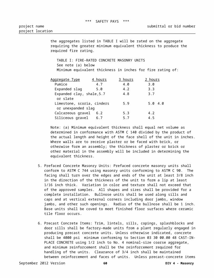
*** SAFETY PAYS ***project name submittal or bid numberproject location
ASTM A1008/A1008M Steel, Sheet, and Strip, Hot-Rolled, Carbon, Structural, High-Strength Low-Alloy and High-Strength Low-Alloy with Improved Formability, Solution Hardened, and Bake Hardened
ASTM A1011/A1011M Steel, Sheet, and Strip, Hot-Rolled, Carbon, Structural, High-Strength Low-Alloy and High-Strength Low-Alloy with Improved Formability
ASTM A123/A123M Zinc (Hot-Dip Galvanized) Coatings on Iron and Steel ProductsASTM A153/A153M Zinc Coating (Hot-Dip) on Iron and Steel HardwareASTM A370 Mechanical Testing of Steel ProductsASTM A653/A653M Steel Sheet, Zinc-Coated (Galvanized) or Zinc-Iron Alloy-Coated
(Galvannealed) by the Hot-Dip ProcessASTM B633 Electrodeposited Coatings of Zinc on Iron and SteelASTM C1007 Installation of Load Bearing (Transverse and Axial) Steel Studs and Related
AccessoriesASTM C955 Load-Bearing (Transverse and Axial) Steel Studs, Runners (Tracks), and
Bracing or Bridging for Screw Application of Gypsum Panel Products and Metal Plaster Bases
ASTM E329 Agencies Engaged in the Testing and/or Inspection of Materials Used in Construction
AMERICAN WELDING SOCIETY (AWS)
AWS D1.3/D1.3M Structural Welding Code - Sheet Steel
SOCIETY OF AUTOMOTIVE ENGINEERS INTERNATIONAL (SAE)
SAE J 78 Steel Self Drilling Tapping Screws
METAL FRAMING MANUFACTURERS ASSOCIATION (MFMA)
MFMA Guidelines for the Use of Metal Framing
General: 1. SUBMITTALS: The following shall be submitted to the Engineer of Record (unless noted otherwise) for approval in accordance with Section 01 33 00.10 06 SUBMITTAL PROCEDURES FOR DESIGN/BUILD:a. Shop Drawings
1) Framing ComponentsA. Cross sections, plans, and/or elevations showing component types and locations for each
framing application; including shop coatings and material thicknesses for each framing component.
B. Connection details showing fastener type, quantity, location, and other information to assure proper installation.
C. Drawings depicting panel configuration, dimensions, components, locations, and construction sequence if the Contractor elects to install prefabricated/prefinished frames.
D. For cold-formed metal framing; drawings, connection details, and design calculations to be signed and sealed by a professional engineer registered in the state where the project is located.
b. Certificates1) Mill Certificates; Mill certificates or test reports from independent testing agency, qualified in
accordance with ASTM E329, showing that the steel sheet used in the manufacture of each cold-formed component complies with the minimum yield strengths and uncoated steel thickness specified. Test reports shall be based on the results of three coupon tests in accordance with ASTM A370.
2) Welds; Certified copies of welder qualifications test records showing qualification in accordance with AWS D1.3.
3) Product Data; Provide data on standard framing members; describe materials and finish, product criteria and limitations. ASTM A370.
September 2012 Version 60 DIV 5 - Metals
*** SAFETY PAYS ***project name submittal or bid numberproject location
4) Product Test Reports; From a qualified testing agency indicating that each of the following complies with requirements, based on comprehensive testing of current products:A. Expansion anchors.B. Mechanical fasteners.C. Vertical deflection clips.D. Miscellaneous structural clips and accessories.
2. DELIVERY, HANDLING AND STORAGE: Materials shall be delivered and handled preventing bending or other damage, and avoiding contact with soil or other contaminating materials. Finish of the framing members shall be maintained at all times, using an approved high zinc dust content, galvanizing repair paint whenever necessary to prevent the formation of rust.
3. System Description: Size components to withstand design loads as indicated on contract drawings. Design wall and/or roof or floor system to provide for movement of components without damage, failure of joint seals, undue stress on fasteners, or other detrimental effects when subject to seasonal or cyclic day/night temperature ranges. Design system to accommodate construction tolerances, deflection of building structural members, and clearances of intended openings.
4. Quality Assurance: Calculate structural properties of framing members in accordance with MFMA - Guide-lines for the Use of Metal Framing and AWS D1.3 requirements. Maintain one copy of each document on site. Manufacturer Qualifications: Company specializing in manufacturing the Products specified in this section. Installer Qualifications: Company specializing in performing the work of this section. Design structural elements under direct supervision of a Professional Structural Engineer experienced in design of this work and licensed in the state where the Project is located.
Products: 1. STEEL STUDS, TRACKS, BRACING, BRIDGING, AND ACCESSORIES: Framing components shall comply with ASTM C955 and the following:a. Material shall be corrosion-resistant steel complying with ASTM A 653/A 653M, 33,000 psi or higher,
having a minimum yield of 33,000 psi and a G 60 minimum zinc coating.b. Studs, joists, rafters and purlins: sheet steel, cold-rolled, punched web for studs only if allowed or
indicated by Engineer, knurled faces, size and gauge as required by design.c. Track: sheet steel, cold-rolled; channel shaped; same width as studs, tight fit; solid web, size and gauge
as required by design.d. Framing Materials: roll from new sheet steel; re-rolled steel not acceptable.e. Struts: ASTM A570 or A525 sheet steel, cold-rolled, size and gauge as required by design.f. Load-bearing framing: Framing members shall have the structural properties indicated. Where
physical structural properties are not indicated, they shall be as necessary to withstand all imposed loads. Design framing in accordance with AISI SG03-3.
2. MARKINGS: Studs and track shall have product markings on the web of the section. The markings shall be repeated throughout the length of the member at a maximum spacing of 4 feet on center and shall be legible and easily read. The product marking shall include the following:a. An ACBO numberb. Manufacturer's identification.c. Minimum delivered uncoated steel thickness.d. Protective coating designator.e. Minimum yield strength.
3. CONNECTIONS: Screws for steel-to-steel connections shall be self-drilling tapping in compliance with SAE J 78 of the type, size, and location as required by design. Electroplated screws shall have a Type II coating in accordance with ASTM B633. Screws, bolts, and anchors shall be hot-dipped galvanized in accordance with ASTM A123/A123M or ASTM A153/A153M as appropriate. Screws bolts and anchors shall be hot dipped galvanized in accordance with ASTM A123/A123M or ASTM A153/A153M as appropriate. Welding in conformance with AWS D1.1 and AWS D1.3.
September 2012 Version 61 DIV 5 - Metals

*** SAFETY PAYS ***project name submittal or bid numberproject location
4. Accessories: Bracing and Bridging: Formed sheet steel, channel shape, size and gauge as required by design. Plates, Gussets, Clips and Angles: Formed sheet steel, size and gauge as required by design. Touch-Up Primer: SSPC paint 20, type I, inorganic, zinc rich.
5. Fabrication: Fabricate assemblies of formed sections of sizes and profiles required; with framing members fitted, reinforced, and braced to suit design requirements. Fit and assemble in largest practical sections for delivery to site, ready for installation.
6. Finishes: Zinc coated (galvanized) by the hot-dip process, G-60 minimum, G-90 as required.
7. MAXIMUM DEFLECTIONS: Maximum deflections permissible are as follows:a. Exterior Studs:
Deflection Criteria Exterior Finish
L/240 or L/360 Synthetic Plaster, Metal PanelsL/360 Cement Plaster, Wood VeneerL/600 Brick Veneer, Stone Panels
Wall deflections shall be computed on the basis that studs withstand all lateral forces independent of any composite action from sheathing materials. Studs abutting windows or louvers shall also be designed not to exceed 1/4 inch maximum deflection.
b. Floor Joists:L/360 - Live load onlyL/240 - Total load
c. Roof Rafters:L/240 - Live load only
SECTION 05 50 00.00 48 – METAL FABRICATIONSScope: 1. Provide miscellaneous metal items fabricated from heavy gage ferrous metals and not provided with
structural steel system:a. Steel pipe handrails and railings.b. Wall ladders.c. Ships ladders.d. Pan stairs and landings.e. Grating stairs and landings.f Checkered Plate Stairs and Landingsg. Loose angle lintels.h. Structural steel door frames.i. Bollards, concrete filled.j. Roof opening steel frames.k. Welded wire fabricl. Floor grating and framesm. Partitions, Diamond mesh typen. Steel door frameso. Trench covers, frames, and linersp. Operable partition supportsq. Overhead coiling door framer. Aluminum rampss. Corner guardst. Trash Guardu. Miscellaneous framing and supports.
September 2012 Version 62 DIV 5 - Metals
*** SAFETY PAYS ***project name submittal or bid numberproject location
References: 1. The publications referenced above (or below) establish minimum requirements for materials, systems and execution that may be specified in this Section.
ALUMINUM ASSOCIATION (AA)
AA 46 Standards for Anodized Architectural AluminumAA DAF-45 Designation System for Aluminum Finishes
AMERICAN INSTITUTE OF STEEL CONSTRUCTION (AISC)
AISC 303 Code of Standard Practice for Steel Buildings and Bridges
AMERICAN SOCIETY OF CIVIL ENGINEERS (ASCE)
ASCE 7-05 Minimum Design Loads for Buildings and Other Structures
AMERICAN SOCIETY OF SAFETY ENGINEERS (ASSE/SAFE)
ASSE/SAFE A10.3 Operations – Safety Requirements for Powder Actuated Fastening Systems
AMERICAN WELDING SOCIETY (AWS)
AWS D1.1/D1.1M Structural Welding Code - Steel
ASME INTERNATIONAL (ASME)
ASME B18.2.1 Square and Hex Bolts and ScrewsASME B18.2.2 Standard for Square and Hex NutsASME B18.21.1 Lock Washers (Inch Series)ASME B18.21.1M Lock Washers (Metric Series)ASME B18.22.1 Plain WashersASME B18.22M Metric Plain WashersASME B18.6.2 Slotted Head Cap Screws, Square Head Set Screws, and Slotted Headless Set
Screws: Inch SeriesASME B18.6.3 Machine Screws and Machine Screw Nuts
AMERICAN NATIONAL STANDARDS INSTITUTE (ANSI)
ANSI A14.3 Ladders - Fixed - Safety Requirements
AMERICAN SOCIETY FOR TESTING AND MATERIALS (ASTM)
ASTM A 36/A 36M Carbon Structural SteelASTM A 53/A 53M Pipe, Steel, Black and Hot-Dipped, Zinc-Coated, Welded and SeamlessASTM A 123/A 123M Zinc (Hot-Dip Galvanized) Coatings on Iron and Steel ProductsASTM A 153/A 153M Zinc Coating (Hot-Dip) on Iron and Steel HardwareASTM A 283/A 283M Low and Intermediate Tensile Strength Carbon Steel PlatesASTM A 307 Carbon Steel Bolts and Studs, 60 000 PSI Tensile StrengthASTM A 467/A 467M Machine Coil and ChainASTM A 47/A 47M Steel Sheet, Aluminum-Coated, by the Hot-Dip ProcessASTM A 475 Zinc-Coated Steel Wire StrandASTM A 48/A 48M Gray Iron CastingsASTM A 500 Cold-Formed Welded and Seamless Carbon Steel Structural Tubing in
Rounds and ShapesASTM A 653/A 653M Steel Sheet, Zinc-Coated (Galvanized) or Zinc-Iron Alloy-Coated
(Galvannealed) by the Hot-Dip Process
September 2012 Version 63 DIV 5 - Metals

*** SAFETY PAYS ***project name submittal or bid numberproject location
ASTM A 687 High-Strength Nonheaded Steel Bolts and StudsASTM A 780 Repair of Damaged and Uncoated Areas of Hot-Dip Galvanized CoatingsASTM A 786/A 786M Hot-Rolled Carbon, Low-Alloy, High-Strength Low-Alloy, and Alloy Steel
Floor PlatesASTM A 924/A 924M General Requirements for Steel Sheet, Metallic-Coated by the Hot-Dip
ProcessASTM B 108/ B108M Standard Specification for Aluminum-Alloy Permanent Mold CastingsASTM B 209 Standard Specification for Aluminum and Aluminum-Alloy Sheet and PlateASTM B 209M Standard Specification for Aluminum and Aluminum-Alloy Sheet and Plate
(Metric)ASTM B 221 Standard Specification for Aluminum and Aluminum-Alloy Extruded Bars,
Rods, Wire, Profiles, and TubesASTM B 221M Standard Specification for Aluminum and Aluminum-Alloy Extruded Bars,
Rods, Wire, Profiles, and Tubes (Metric)ASTM B 26/B 26M Standard Specification for Aluminum-Alloy Sand CastingsASTM B 633 Electrodeposited Coatings of Zinc On Iron And SteelASTM D 1187 Asphalt-Base Emulsions for Use as Protective Coatings for MetalASTM D 2047 Static Coefficient of Friction of Polish-Coated Floor Surfaces as Measured by
the James MachineASTM E 488 Standard Test Method for Strength of Anchors in Concrete and Masonry
ElementsASTM F 1267 Metal, Expanded, SteelASTM F 1679 Standard Test Method for Using a Variable Incidence Tribometer
AMERICAN WELDING SOCIETY (AWS)
AWS D1.1 Structural Welding Code – Steel
MASTER PAINTERS INSTITUTE (MPI)
MPI 79 Alkyd Anti-Corrosive Metal Primer
NATIONAL ASSOCIATION OF ARCHITECTURAL METAL MANUFACTURERS (NAAMM)
NAAMM MBG 531 Metal Bar Grating ManualNAAMM MBG 532 Heavy Duty Metal Bar Grating Manual
NATIONAL FIRE PROTECTION ASSOCIATION (NFPA)
NFPA 211 Chimneys, Fireplaces, Vents, and Solid Fuel-Burning Appliances
THE SOCIETY FOR PROTECTIVE COATINGS (SSPC)
SSPC SP 3 Power Tool CleaningSSPC SP 6 Commercial Blast Cleaning
Submittals: 1. Shop Drawings: Detail drawings indicating material thickness, type, grade, and class; dimensions; and construction details. Drawings shall include catalog cuts, erection details, manufacturer's descriptive data and installation instructions, and templates. Detail drawings for the following items:
Steel pipe handrails and railings.Wall ladders.Ships ladders.Pan stairs and landings.Grating stairs and landings.
September 2012 Version 64 DIV 5 - Metals

*** SAFETY PAYS ***project name submittal or bid numberproject location
Checkered Plate Stairs and LandingsLoose angle lintels.Structural steel door frames.Bollards, concrete filled.Roof opening steel frames.Welded wire fabricFloor grating and framesPartitions, Diamond mesh typeSteel door framesTrench covers, frames, and linersOperable partition supportsOverhead coiling door frameAluminum rampsCorner guardsTrash GuardMiscellaneous framing and supports
Products: 1. Materials:a. Steel plates, shapes, and bars: ASTM A 36/A 36M.b. Sheet steel: ASTM A570.c. Stainless steel sheet: ASTM A167, Type 302/304.d. Checkered Steel Floor Plates: FS QQ-F-461C(1), Class 1.e. Steel tubing: ASTM A 53, schedule 40.f. Bolts, nuts and washers: ASTM A 307.g. Grout: Non-shrink non-metallic grout.h. Concrete inserts: Galvanized ferrous castings.i. Steel Tubing: ASTM A 500, Grade Bj. Plates: ASTM A 283/A 283 Mk. Pipe: ASTM A 53, Grade B, Sched 40l. Extruded Aluminum: ASTM B 221, Alloy 6063, Temper T6m. Sheet Aluminum: ASTM B 209, Alloy 6063, Temper T6n. Aluminum-Alloy Drawn Seamless Tubes: ASTM B 210, Alloy 6063, Temper T6o. Aluminum-Alloy Bars: ASTM B 211, Alloy 6063, Temper T6p. Bolts and Nuts: ASTM A 307 and ASTM A 563q. Screws: ASTM B 186.3r. Expansion Anchors: ASTM B 633, capable to sustain, without failure, a load capacity equal to 6 times
the load imposed when installed in unit masonry and 4 times when installed in concrete as determined by testing per ASTM E 488
s. Welding Materials: AWS D1.1 of the type required for materials being welded.t. Concrete for Landings and Treads: Portland cement Type I, 4000 psi 28 day strength, 3 to 5 in slump.u. Landing Concrete Reinforcement: Mesh type galvanized.
2. Galvanized ferrous metal items at exterior and where exposed to weather; 1 coat primer (shop-applied) elsewhere.a. Galvanizing: ASTM A 386.b. Primer Paint: Fabricator's standard gray primer, 2.0 mils thickness.c. Galvanizing repair compound.
Fabrication: 1. Corner Guards And Shields: Corner guards and shields for jambs and sills of openings and edges of platforms shall be steel shapes and plates anchored in masonry or concrete with welded steel straps or end weld stud anchors. Corner guards for use with glazed or ceramic tile finish on walls shall be formed of 0.0625 inches thick corrosion-resisting steel with polished or satin finish, shall extend 5 feet above the top of cove base or to the top of the wainscot, whichever is less, and shall be securely anchored to the supporting wall. Corner guards on exterior shall be galvanized. Corner guards for Kitchens shall be stainless steel.
September 2012 Version 65 DIV 5 - Metals

*** SAFETY PAYS ***project name submittal or bid numberproject location
2. Pipe Guards (Bollards): Pipe guards shall be heavy duty steel pipe conforming to ASTM A 53/A 53M, Type E or S, weight XS, black finish.
3. Floor Gratings And Frames: Carbon steel and Aluminum grating shall be designed in accordance with NAAMM MBG 531 to meet the indicated load requirements. Edges shall be banded with bars ¼ inch less in height than bearing bars for grating sizes above 3/4 inch. Banding bars shall be flush with the top of bearing grating. Frames shall be of welded steel construction finished to match the grating. Steel floor gratings and frames shall be galvanized after fabrication. Aluminum grating shall be alloy 6063-T6 conforming to ASTM B 221. Grating shall conform to NAAMM metal Bar Grating Manual designated ANSI/NAAMM MBG 531. Grating Type shall be Rectangular Bar SG Series. Provide aluminum saddle clips for grating hold down.
4. Floor Plates: Floor plates shall be 6 mm thick, raised pattern steel galvanized.
5. Handrails: Handrails shall be designed to resist a concentrated load of 200 lbs in any direction at any point of the top of the rail or 20 lbs/foot applied horizontally to top of the rail, whichever is more severe. Steel handrails, including inserts in concrete, shall be steel pipe conforming to ASTM A 53/A 53M or structural tubing conforming to ASTM A 500, Grade A or B of equivalent strength. Steel railings shall be 1 ½ inches nominal size. Railings shall be hot-dip galvanized and shop painted primed. Pipe collars shall be hot-dip galvanized steel. Joint posts, rail, and corners shall be fabricated by one of the following methods:1) Flush type rail fittings of commercial standard, welded and ground smooth with railing splice locks
secured with hexagonal recessed-head set screws.2) Mitered and welded joints by fitting post to top rail and intermediate rail to post, mitering corners,
groove welding joints, and grinding smooth. Railing splices shall be butted and reinforced by a tight fitting interior sleeve not less than 6 inches long.
3) Railings may be bent at corners in lieu of jointing, provided bends are made in suitable jigs and the pipe is not crushed.
4) Removable sections, toe-boards, and brackets shall be provided as indicated.
6. Ladders: Ladders shall be galvanized steel or aluminum, fixed rail type in accordance with ANSI A14.3.
7. Miscellaneous: Miscellaneous plates and shapes for items that do not form a part of the structural steel framework, such as lintels, sill angles, miscellaneous mountings, and frames, shall be provided to complete the work.
8. Partitions, Diamond Mesh Type: Partitions shall be constructed of metal fabric attached to structural steel framing members. Fabric shall be 10 gauge steel wires woven into 1 ½ inch diamond mesh with wire secured through weaving channels. Framing members shall be channels 1 ½ inch by 3/8 inch minimum size. Channel frames shall be mortised and tenoned at intersections. Steel frames, posts, and intermediate members shall be of the sizes and shapes indicated. Cast-iron floor shoes and caps shall have set screw adjustment. Doors and grilles shall be provided as indicated, complete with hardware and accessories including sliding mechanisms, locks, guard plates, sill shelves and brackets, and fixed pin butts. Doors and grilles shall have cover plates as indicated. Dutch doors shall have a lock for each leaf. A continuous rubber bumper shall be provided at bottom of grille frame. Locks shall be bronze, cylinder, mortise type. Keying shall be coordinated with Section 08 70 00.00 48 DOOR HARDWARE. Ferrous metal portions of partitions and accessories shall be galvanized.
9. Steel Door Frames: Steel door frames built from structural shapes shall be neatly mitered and securely welded at the corners with all welds ground smooth. Jambs shall be provided with 2 by 1/4 by 12 inch bent, adjustable metal anchors spaced not over 2 feet 6 inch on centers. Provision shall be made to stiffen the top member for all spans over3 foot. Continuous door stops shall be made of 1-1/2 by 5/8 inch bars.
10. Trench Covers, Frames, And Liners: Trench grating shall be ductile iron load capacity Class C, heavy duty. Trench frames and anchors shall be all welded steel construction designed to match cover. Grating opening
September 2012 Version 66 DIV 5 - Metals

*** SAFETY PAYS ***project name submittal or bid numberproject location
widths shall not exceed 1 inch. The channel for trench drain shall have a built-in slope of 1/8 inch per foot. The channels shall be constructed of minimum 1/8 inch thick fiberglass.
11. Dissimilar Materials: Where dissimilar materials are in contact, or where aluminum is in contact with concrete, mortar, masonry, wet or pressure treated wood, or absorptive materials subject to wetting, the surfaces shall be protected with a coat of bituminous paint or asphalt varnish.
12. Trash Guard: Trash Guards shall be ASTM A 283 minimum 3/4 inch galvanized steel bars, transverse and longitudinal spacing as indicated on the drawings and welded a each bar intersection.
13. Concrete-Filled Metal Pan Stairs And Landings: Steel stairs shall be complete with structural or formed channel stringers, metal pan cement-filled treads or grating treads as indicated on the drawings, landings, columns, handrails, and necessary bolts and other fastenings as indicated. Structural steel shall conform to ASTM A 36/A 36M. Stairs and accessories shall be galvanized and factory primed coated. Risers on stairs with metal pan treads shall be deformed to form a sanitary cove to retain the tread concrete. Integral nosings shall have braces extended into the concrete fill. Gratings for treads and landings shall conform to NAAMM MBG 531. Grating treads shall have slip-resistant nosings.
14. Welded Wire Fabric: Welded wire fabric where indicated at stair rails shall be constructed of metal fabric attached to steel framing members. Fabric shall be 10 gauge welded wire mesh, hot dipped galvanized, factory primed, steel wires woven into 1-1/2 inch diamond mesh.
September 2012 Version 67 DIV 5 - Metals

*** SAFETY PAYS ***project name submittal or bid numberproject location
DIVISION 06 – WOOD, PLASTICS, AND COMPOSITES
SECTION 06 10 00.00 48 – ROUGH CARPENTRYScope: 1. Provide rough carpentry work:
a. Wood framing.b. Sheathing.c. Nailers, blocking, and furring.d. Equipment backing panels.e. Roof curbs and cants.f. Blocking in wall and roof openingsg. Wood furring and groundsh. Concealed wood blocking for support of toilet and bath accessories and wall cabinets.i. Preservative treatment of wood.j. Fire Retardant treatment of wood where required
References: 1. The publications referenced above (or below) establish minimum requirements for materials, systems and execution that may be specified in this Section.
AMERICAN FOREST & PAPER ASSOCIATION (AF&PA)
AF&PA T01 National Design Specification for Wood ConstructionAF&PA T11 Manual for Wood Frame Construction
AMERICAN HARDBOARD ASSOCIATION (AHA)
AHA A194.1 Cellulosic Fiber Board
AMERICAN SOCIETY FOR TESTING AND MATERIALS (ASTM)
ASTM A 307 Carbon Steel Bolts and Studs, 60 000 PSI Tensile StrengthASTM A 653/A 653M Standard Specification for Steel Sheet, Zinc-Coated (Galvanized) or Zinc-Iron
Alloy Coated (Galvannealed) by the Hot Dip ProcessASTM C 79/C 79M Treated Core and Nontreated Core Gypsum Sheathing BoardASTM C 518 Steady-State Heat Flux Measurements and Thermal Transmission Properties
By Means of the Heat Flow Meter ApparatusASTM C 1177/C 1177M Glass Mat Gypsum Substrate for Use as SheathingASTM D 2898 Accelerated Weathering of Fire-Retardant-Treated Wood for Fire TestingASTM D 6007 Standard Test Method for Determining Formaldehyde Concentration in Air
from Wood Products Using a Small Scale ChamberASTM F 547 Definitions of Terms Relating to Nails for Use with Wood and Wood-Base
Materials
AMERICAN WOOD-PRESERVERS' ASSOCIATION (AWPA)
AWPA C2 Lumber, Timber, Bridge Ties and Mine Ties - Preservative Treatment by Pressure Processes
AWPA C9 Plywood - Preservative Treatment by Pressure ProcessesAWPA C20 Structural Lumber Fire-Retardant Pressure TreatmentAWPA C27 Plywood - Fire-Retardant Pressure TreatmentAWPA M4 Standard for the Care of Preservative-Treated Wood ProductsAWPA P5 Standards for Waterborne Preservatives
CALIFORNIA REDWOOD ASSOCIATION (CRA)
September 2012 Version 68 DIV 6 – Wood, Plastics and Composites

*** SAFETY PAYS ***project name submittal or bid numberproject location
CRA RIS-01-SS Standard Specifications for Grades of California Redwood Lumber
COMPOSITE PANEL ASSOCIATION (CPA)
CPA A208.1 Medium Density Fiberboard (MDF) For Interior Applications
FACTORY MUTUAL ENGINEERING AND RESEARCH (FM)
FM LPD 1-49 Loss Prevention Data Sheet - Perimeter Flashing
NATIONAL HARDWOOD LUMBER ASSOCIATION (NHLA)
NHLA Rules Rules for the Measurement & Inspection of Hardwood & Cypress
NORTHEASTERN LUMBER MANUFACTURERS ASSOCIATION (NELMA)
NELMA Grading Rules Standard Grading Rules for Northeastern Lumber
SOUTHERN CYPRESS MANUFACTURERS ASSOCIATION (SCMA)
SCMA Specs Standard Specifications for Grades of Southern Cypress
SOUTHERN PINE INSPECTION BUREAU (SPIB)
SPIB Rules Standard Grading Rules for Southern Pine Lumber
WEST COAST LUMBER INSPECTION BUREAU (WCLIB)
WCLIB Std 17 Grading Rules for West Coast Lumber
WESTERN WOOD PRODUCTS ASSOCIATION (WWPA)
WWPA Grading Rules Western Lumber Grading Rules 95
Products: 1. Lumber, finished 4 sides, with moisture content of 15 percent for 2-inch nominal thickness or less, 19 percent for more than 2-inch nominal thickness :a. Solid sawn and finger-jointed lumber shall bear an authorized grade stamp or grade mark recognized
by ALSC, or an ALSC recognized certification stamp, mark, or hammer brand. Surfaces that are to be exposed to view shall not bear grade marks, stamps, or any type of identifying mark. Hammer marking will be permitted on timbers when all surfaces will be exposed to view
b. Light framing: Construction grade Douglas fir or southern pine, appearance grade where exposed.c. Structural framing and timbers: No. 1 grade Douglas fir or southern pine, appearance grade where
exposed.d. Boards: Construction grade.
2. Wood for nailers, blocking, and furring: Blocking shall be standard or number 2 grade, finished 4 sides, with moisture content of 15 percent for 2-inch nominal thickness or less, 19 percent for more than 2-inch nominal thickness.. Pressure preservative treat items in contact with roofing, flashing, waterproofing, masonry, concrete or the ground.
3. Plywood, APA rated for use and exposure:a. Materials shall bear the grade mark or other identifying marks indicating grades of material and rules
or standards under which produced, including requirements for qualifications and authority of the inspection organization. Except for plywood and wood structural panels, bundle marking will be
September 2012 Version 69 DIV 6 – Wood, Plastics and Composites

*** SAFETY PAYS ***project name submittal or bid numberproject location
permitted in lieu of marking each individual piece. Surfaces that are to be exposed to view shall not bear grade marks or other types of identifying marks.
4. Sheathing shall be fiberboard, gypsum board, or plywood, for wall sheathing as indicated on the drawings; and plywood, wood structural panels, or gypsum board, for roof sheathing as indicated on the drawings.a. Fiberboard shall conform to ASTM C 208, Type IV, Grade 2, Structural Grade, or AHA A194.1,
Type IV, Grade 2 asphalt impregnated or asphalt coated to be water-resistant but vapor permeable.b. Glass mat gypsum sheathing shall conform to ASTM C 79/C 79M and ASTM C 1177/C 1177M.c. Gypsum board shall conform to ASTM C 79/C 79M, 1/2 inch thick, 4 feet wide with straight edges for
supports 16 inches on center without corner bracing of framing or for supports 24 inches with V-tongue and groove edges for supports 16 or 24 inches on center with corner bracing of framing.
d. Plywood shall conform to APA PRP-108, Grade C-D or sheathing grade with exterior glue. Sheathing for roof and walls without corner bracing of framing shall have a span rating of 16/0 or greater for supports 400 mm on center and a span rating of 24/0 or greater for supports 24 inches on center
5. Anchor Bolts shall conform to ASTM A 307, size as indicated, complete with nuts and washers.
6. Nails and Staples shall conform to ASTM F 547, size and type best suited for purpose; staples shall be as recommended by the manufacturer of the materials to be joined.
7. Nails used with treated lumber and sheathing shall be galvanized. Nailing shall be in accordance with the recommended nailing schedule contained in AF&PA T11. Where detailed nailing requirements are not specified, nail size and spacing shall be sufficient to develop an adequate strength for the connection. The connection's strength shall be verified against the nail capacity tables in AF&PA T01
8. Building Paper: No.15 asphalt felt.
9. Wood Treatment:a. Preservative treatment: Pressure-treated with waterborne preservatives, to comply with AWPA -C2
(Lumber) and C9 (Plywood) with waterborne preservatives listed in AWPA P5, as applicable. Kiln dry to 15% max. moisture content.
b. Exposed areas of treated wood that are cut or drilled after treatment shall receive a field treatment in accordance with AWPA M4. Items of all-heart material of cedar, cypress, or redwood will not require preservative treatment, except when in direct contact with soil. Except as specified for all-heart material of the previously mentioned species, the following items shall be treated:1) Wood members in contact with or within 18 inches of soil.2) Wood members in contact with water.3) Wood members exposed to the weather including those used in built up roofing systems or as
nailing strips or nailers over fiberboard or gypsum-board wall sheathing as a base for wood siding.4) Wood members set into concrete regardless of location, including flush-with-deck wood nailers
for roofs.5) Wood members in contact with concrete that is in contact with soil or water or that is exposed to
weather.c. Fire-retardant treatment: Pressure impregnated, to comply with AWPA C20 (lumber) and C27
(plywood); provide where indicated and where required by code. Fire-retardant treated plywood will not be used in any part of the roof or roofing system1) Material use shall be defined in AWPA C20 and AWPA C27 for Interior Type A and B and
Exterior Type. Treatment and performance inspection shall be by an independent and qualified testing agency that establishes performance ratings.
10. Sustainable Design Requirements: See Section 01 02 00.00 48 for LEED™ requirements.
September 2012 Version 70 DIV 6 – Wood, Plastics and Composites

*** SAFETY PAYS ***project name submittal or bid numberproject location
SECTION 06 20 00.00 48 – FINISH CARPENTRYScope: 1. Provide finish carpentry for woodwork items exposed to view:
a. Chair Railsb. Fiberglass Reinforced Plastic
References: 1. The publications referenced above (or below) establish minimum requirements for materials, systems and execution that may be specified in this Section.
AMERICAN SOCIETY FOR TESTING AND MATERIALS (ASTM)
ASTM F 547 Definitions of Terms Relating to Nails for Use with Wood and Wood-Base Materials
AMERICAN WOOD-PRESERVERS' ASSOCIATION (AWPA)
AWPA C9 Plywood - Preservative Treatment by Pressure ProcessesAWPA P5 Standards for Waterborne Preservatives
COMPOSITE PANEL ASSOCIATION (CPA)
CPA A208.1 Medium Density Fiberboard (MDF) For Interior Applications
Products: 1. Grading and Marking: Materials shall bear the grade mark, stamp or other identifying marks indicating grades of material and rules or standards under which produced. Such identifying marks on a material shall be in accordance with the rule or standard under which the material is produced, including requirements for qualifications and authority of the inspection organization, usage of authorized identification, and information included in the identification. The inspection agency for lumber shall be certified by the Board of Review, American Lumber Standards Committee, to grade the species used. Except for plywood, wood structural panels, and lumber, bundle marking will be permitted in lieu of marking each individual piece. Surfaces that are to be architecturally exposed to view shall not bear grade marks, stamps, or other types of identifying marks.
2. Moisture Content: The maximum moisture content of untreated trim and wood siding shall be 15 percent at the time of delivery to the jobsite and when installed. Moisture content of all other material shall be in accordance with the standard under which the product is produced.
3. Preservative Treatment: Plywood shall be treated in accordance with AWPA C9 with waterborne preservatives listed in AWPA P5.
4. Woodwork Items: Materials and fabrication requirements for woodwork items not listed in this guide specification will be added or modified as necessary for the project:a. Chair Rails: AWI Profile [CHR 6001] [ ], Grade 1, premium quality, White Oak, plain sawn with
inside mitered corners.b. Fiberglass Reinforced Plastic Sheet: 3/32 inch thick fiberglass reinforced plastic (FRP) sheet having a
Class A flame spread (25 or less) and a smoke developed of 200 when tested according to ASTM E84. Adhesive and sealant as recommended by manufacturer. Color: Manufacturer's standard White. Provide largest standard size material available to minimize joints
5. Nails shall be the size and type best suited for the purpose and shall conform to ASTM F 547. Nails shall be hot-dip galvanized or aluminum when used on exterior work. Screws for use where nailing is impractical shall be size best suited for purpose.
6. Sustainable Design Requirements: See Section 01 02 00.00 48 for LEED™ requirements.
September 2012 Version 71 DIV 6 – Wood, Plastics and Composites
*** SAFETY PAYS ***project name submittal or bid numberproject location
SECTION 06 41 16.00 48 – CUSTOM CABINETSScope: 1. Provide shop-fabricated exposed woodwork and casework:
a. Laminate clad casework and hardware.
References: 1. The publications referenced above (or below) establish minimum requirements for materials, systems and execution that may be specified in this Section.
ARCHITECTURAL WOODWORK INSTITUTE (AWI)
AWI Quality Standards Architectural Woodwork Quality Standards.
NATIONAL ELECTRICAL MANUFACTURERS ASSOCIATION (NEMA)
NEMA LD 3 High Pressure Decorative LaminatesNEMA LD 3.1 Performance, Application, Fabrication, and Installation of High Pressure
Decorative Laminates
AMERICAN NATIONAL STANDARD INSTITUTE (ANSI)
ANSI A161.2 Decorative Laminate Countertops, Performance Standards for Fabricated High Pressure
ANSI A208.1 Particleboard Mat Formed WoodsANSI A208.2 Medium Density Fiberboard (MDF)
AMERICAN SOCIETY FOR TESTING AND MATERIALS (ASTM)
ASTM D 1037 Evaluating Properties of Wood-Base Fiber and Particle Panel MaterialsASTM F 547 Definition of Terms Relating to Nails for Use with Wood and Wood-Based
Materials.
BUILDERS HARDWARE MANUFACTURERS ASSOCIATION (BHMA)
BHMA A156.9 Cabinet Hardware
NATIONAL WOOD WINDOW & DOOR ASSOCIATION (NWWDA)
NWWDA I.S. 1-A Architectural Wood Flush Doors
Submittals: 1. Shop Drawings: Shop drawings showing all fabricated casework items in plan view, elevations and cross-sections to accurately indicate materials used, details of construction, dimensions, methods of fastening and erection, and installation methods proposed. Shop drawing casework items shall be clearly cross-referenced to casework items located on the project drawings. Shop drawings shall include a color schedule of all casework items to include all countertop, exposed, and semi-exposed cabinet finishes to include finish material manufacturer, pattern, and color.
2. Product Data: Descriptive data which provides narrative written verification of all types of construction materials and finishes, methods of construction, etc. not clearly illustrated on the submitted shop drawings. Data shall provide written verification of conformance with AWI Quality Standards for the quality indicated to include materials, tolerances, and types of construction. Both the manufacturer of materials and the fabricator shall submit available literature which indicates compliance with LEED™ requirements for pursued credits.
Quality Assurance: 1. Unless otherwise noted on the drawings, all materials, construction methods, and fabrication shall conform to and comply with the custom grade quality standards as outlined in AWI Quality Standards, Section 400G and Section 400B for laminate clad cabinets. These standards shall apply in lieu of omissions or specific requirements in this specification.
September 2012 Version 72 DIV 6 – Wood, Plastics and Composites

*** SAFETY PAYS ***project name submittal or bid numberproject location
Products: 1. Lumber: All framing lumber shall be kiln-dried Grade III to dimensions as shown on the drawings. Frame front, where indicated on the drawings, shall be nominal 3/4 inch hardwood.
2. Standing and Running Trim: Standing or running trim casework components which are specified to receive a transparent finish shall be white oak hardwood species, plain sawn. AWI grade shall be custom. Location, shape, and dimensions shall be as indicated on the drawings.
3. Panel Products:a. Particleboard: All particleboard shall be industrial grade, medium density 40 to 50 pounds per cubic
foot, 3/4 inch thick. A moisture-resistant particleboard in grade Type 2-M-2 or 2-M-3 shall be used as the substrate for plastic laminate covered countertops, backsplashes and doors and components as located on the drawings and other areas subjected to moisture. Particleboard shall meet the minimum standards listed in ASTM D 1037 and ANSI A208.1
b. Medium Density Fiberboard: Medium density fiberboard (MDF) shall be an acceptable panel substrate where noted on the drawings. Medium density fiberboard shall meet the minimum standards listed in ANSI A208.2.
c. Solid surfacing casework components shall conform to the requirements of Section 06 60 00.00 48 PLASTIC FABRICATIONS.
4. Plastic Laminates: All plastic laminates shall meet the requirements of NEMA LD 3 and ANSI A161.2 for high-pressure decorative laminates. Design, colors, surface finish and texture, and locations shall be as selected by the Architect and accepted by the Government. Plastic laminate types and nominal minimum thickness for casework components shall be as indicated in the following paragraphs.a. Horizontal General Purpose Standard (HGS) Grade: Horizontal general purpose standard grade plastic
laminate shall be 0.048 inches (plus or minus 0.005 inches) in thickness. This laminate grade is intended for horizontal surfaces where postforming is not required.
b. Vertical General Purpose Standard (VGS) Grade: Vertical general purpose standard grade plastic laminate shall be 0.028 inches (plus or minus 0.004 inches) in thickness. This laminate grade is intended for exposed exterior vertical surfaces of casework components where postforming is not required.
c. Backing Sheet (BK) Grade: Undecorated backing sheet grade laminate is formulated specifically to be used on the backside of plastic laminated panel substrates to enhance dimensional stability of the substrate. Backing sheet thickness shall be 0.020 inches. Backing sheets shall be provided for all laminated casework components where plastic laminate finish is applied to only one surface of the component substrate.
5. All hardware shall conform to BHMA A156.9, unless otherwise noted, and shall consist of the following components:a. Door Hinges: Euro-style with concealed knuckle; 170 degrees swing with self closing capability at
less than 90 degrees to its closed position. Clip concealed hinge shall pass Section 4.2 (Hinge Operating Life Test) and 4.3 (Self Closing Hinge Test) of ANSI/BHMA A 156.9. Hinges to be nickel plated.
b. Cabinet Pulls: Wire pulls with center to center dimension of 3 1/2 inches, outer dimension of 0.30 inches in diameter; and a projection of 1 1/4 inches. The wire pulls shall be stainless steel in a US32D finish
c. Drawer Slide: Side mounted type, Grade 1 with full extension and a minimum dynamic rating of 75 pounds and static rating of 100 pound load capacity. Slides shall have a self close/stay close action, epoxy coated steel, nylon rollers, captive RH profiles, tolerance compensating LH profile, 1/2 inch side clearance and a double warning stop with lock-out position to avoid accidental drawer removal
d. Adjustable Shelf Support System: Multiple holes with metal pin supports.
6. Nails, screws, and other suitable fasteners shall be the size and type best suited for the purpose and shall conform to ASTM F 547 where applicable.
September 2012 Version 73 DIV 6 – Wood, Plastics and Composites

*** SAFETY PAYS ***project name submittal or bid numberproject location
7. Adhesives shall be of a formula and type recommended by AWI. Adhesives shall be selected for their ability to provide a durable, permanent bond and shall take into consideration such factors as materials to be bonded, expansion and contraction, bond strength, fire rating, and moisture resistance. Adhesives shall meet local regulations regarding VOC emissions and off-gassing.
8. Wood Joinery: Adhesives used to bond wood members shall be a Type II for interior use as recommended by the manufacturer. Adhesives shall withstand a bond test as described in NWWDA I.S. 1-A
9. Laminate Adhesive: Adhesive used to join high-pressure decorative laminate to wood shall be an adhesive consistent with AWI and laminate manufacturer's recommendations. PVC edge banding shall be adhered using a polymer-based hot melt glue.
10. Caulk used to fill voids and joints between laminated components and between laminated components and adjacent surfaces shall be clear, 100 percent silicone.
11. Sealant shall be of a type and composition recommended by the substrate manufacturer to provide a moisture barrier at sink cutouts and all other locations where unfinished substrate edges may be subjected to moisture.
12. Finishes: Paint, stain, varnish and their applications required for laminate clad casework components shall be as selected.
13. Accessories: Grommets shall be plastic material for cutouts with a diameter of 2 1/2 inches. Locations shall be as indicated on the drawings.
14. Sustainable Design Requirements: See Section 01 02 00.00 48 for LEED™ requirements
SECTION 06 611 160.00 48 – SOLID POLYMER FABRICATIONSScope: 1. Solid Surfacing
2. Cultured Marble
References: 1. The publications referenced above (or below) establish minimum requirements for materials, systems and execution that may be specified in this Section.
AMERICAN NATIONAL STANDARDS INSTITUTE (ANSI)
ANSI A136.1 Organic Adhesives for Installation of Ceramic TileANSI Z124.3 Plastic LavatoriesANSI Z124.6 Plastic Sinks
Submittals: 1. Product Data: Product data indicating product description, fabrication information, and compliance with specified performance requirements for solid polymer, joint adhesive, sealants, and heat reflective tape. Both the manufacturer of materials and the fabricator shall submit documentation indicating compliance with LEED™ requirements for pursued credits.
Products: 1. Solid polymer material shall be a homogeneous filled solid polymer; not coated, laminated or of a composite construction; meeting ANSI Z124.3 and ANSI Z124.6 requirements. Material shall have minimum physical and performance properties specified. Superficial damage to a depth of 0.01 inch shall be repairable by sanding or polishing. Material thickness shall be 1/2 inches. In no case shall material be less than 1/4 inch in thickness (vertical surfaces only). Color as selected by the Architect and accepted by the Government.
2. Cultured Marble: Cultured marble window sills shall conform to ANSI Z124.3 having a minimum 18 mils gelcoat. Cultured marble window sills polyester resin based, inert mineral filled one piece units and a
September 2012 Version 74 DIV 6 – Wood, Plastics and Composites

*** SAFETY PAYS ***project name submittal or bid numberproject location
minimum of 5/8 inch thick with eased edges. Color as selected by the Architect and accepted by the Government.
4. Adhesives as recommended by the manufacturer.
5. Sustainable Design Requirements: See Section 01 02 00.00 48 for LEED™ requirements
September 2012 Version 75 DIV 6 – Wood, Plastics and Composites
*** SAFETY PAYS ***project name submittal or bid numberproject location
DIVISION 07 – THERMAL AND MOISTURE PROTECTION
SECTION 07 11 00.00 48 – BITUMINOUS DAMPPROOFINGScope: 1. Bituminous dampproofing applied to CMU back-up wall in cavity wall construction.
References: 1. The publications referenced above (or below) establish minimum requirements for materials, systems and execution that may be specified in this Section.
AMERICAN SOCIETY FOR TESTING AND MATERIALS (ASTM)
ASTM D 41 Asphalt Primer Used in Roofing, Dampproofing, and WaterproofingASTM D 1227 Emulsified Asphalt Used as a Protective Coating for RoofingASTM D 4479 Asphalt Roof Coatings - Asbestos Free
Submittals: 1. Product Data: Product data indicating product description, fabrication information, and compliance with specified performance requirements
2. Certificates: Certificates attesting that the materials meet the requirements specified.
Products: 1. Emulsion-Based Asphalt Dampproofing:a. Fibrated Emulsion-Based Asphalt: Fibrated emulsion-based asphalt dampproofing shall be cold-
applied type conforming to ASTM D 1227 Type IV, asbestos-free, manufactured of refined asphalt, emulsifiers and selected clay, fibrated with mineral fibers. For spray or brush application, emulsion shall contain a minimum of 59 percent solids by weight, 56 percent solids by volume. For trowel application, emulsion shall contain a minimum of 58 percent solids by weight, 55 percent solids by volume.
2. Solvent-Based Asphalt Dampproofing:a. Asphaltic Primer: Primer for cold-applied solvent-based asphalt dampproofing shall conform to
ASTM D 41, asbestos-free, non-fibrated, manufactured with highly ductile soft asphalts and selected hydrocarbons.
b. Fibrated Asphalt: Fibrated solvent-based asphalt dampproofing shall be cold-applied type conforming to ASTM D 4479 Type I, asbestos-free, manufactured with selected asphalts, stabilizers, mineral spirits and fibrated with mineral fibers. Solvent-based asphalt shall contain 72 percent solids by weight, 65 percent solids by volume.
SECTION 07 13 00.00 48– BITUMINOUS WATERPROOFINGScope: 1. Bituminous waterproofing for below grade use and waterproofing for work specified in
Section 09 30 00.00 48 CERAMIC TILE
References: 1. The publications referenced above (or below) establish minimum requirements for materials, systems and execution that may be specified in this Section.
AMERICAN SOCIETY FOR TESTING AND MATERIALS (ASTM)
ASTM D 41 Asphalt Primer Used in Roofing, Dampproofing, and WaterproofingASTM D 173 Bitumen-Saturated Cotton Fabrics Used in Roofing and WaterproofingASTM D 449 Asphalt Used in Dampproofing and WaterproofingASTM D 1327 Bitumen-Saturated Woven Burlap Fabrics Used in Roofing and
WaterproofingASTM D 1668 Glass Fabrics (Woven and Treated) for Roofing and WaterproofingASTM D 4586 Asphalt Roof Cement, Asbestos Free
Submittals: 1. Product Data:
September 2012 Version 76 DIV 7 – Thermal and Moisture Protection
*** SAFETY PAYS ***project name submittal or bid numberproject location
a. Manufacturer's data including technical information which indicates full compliance with this section.b. Manufacturer's installation instructions, before delivery of materials to the site. Instructions shall
specify acceptable range of asphalt application temperatures and the maximum temperature for holding asphalt in a heated condition.
2. Certificates: Certificates from manufacturer attesting that asphalt manufactured and shipped to jobsite meets the specified requirements.
Products: 1. Asphalt Waterproofinga. Primer for hot-applied asphalt waterproofing shall conform to ASTM D 41, asbestos-free, non-
fibrated, manufactured with highly ductile soft asphalts and selected hydrocarbons.b. Below-Grade Hot-Applied Asphalt: Hot-applied asphalt for below-grade applications shall conform to
ASTM D 449, Type I, asbestos-free, manufactured from crude petroleum, suitable for use with membrane waterproofing systems
c. Reinforcement Fabrics:1) Cotton Fabrics: Cotton fabrics shall be woven entirely of cotton conforming with ASTM D 173,
thoroughly and uniformly saturated with asphalt.2) Woven Burlap Fabrics: Woven burlap fabrics shall be composed of 100 percent jute fiber and two
cotton threads at each selvage conforming with ASTM D 1327, thoroughly and uniformly saturated with asphalt. The fabric mesh shall not be completely closed or sealed by the process of saturation. Sufficient porosity shall be maintained to allow successive moppings of the plying asphalt to seep through. The surface shall not be coated or covered with talc or any other substances that will interfere with the adhesion between fabric and plying asphalt. The fabric surface shall be uniformly smooth and free of irregularities, folds and knots. The finished woven burlap fabrics shall be free of ragged edges, untrue edges, breaks or cracks, and other visible external defects.
3) Glass Fabrics: Glass fabrics shall conform to ASTM D 1668 Type I, asphalt-treated woven glass waterproofing fabrics coated with asphalt.
d. Flashing Cement: Flashing cement shall conform to ASTM D 4586, Type I, trowel grade, asbestos free, manufactured from asphalts characterized as adhesive, healing and ductile.
e. Insulation Boards: Insulation boards shall conform to ASTM C 208 cellulosic fiber boards, construction grade, 1/2 inch thick, fibrous-felted homogeneous panel. Insulation boards shall be manufactured from ligno-cellulosic fibers (wood or cane) by a felting or molding process, asphalt-saturated or coated, with a density of 10 to 31 lbs. per square foot. Surfaces of insulation boards shall be free of cracks, lumps, excessive departure from planeness, or other defects that adversely affect performance.
SECTION 07 19 00.00 48 – WATER REPELLENT COATINGScope: 1. Provide clear, penetrating water repellent coating for exterior exposed masonry, stone, stucco, and concrete
walls.
References: 1. The publications referenced above (or below) establish minimum requirements for materials, systems and execution that may be specified in this Section.
AMERICAN ARCHITECTURAL MANUFACTURERS ASSOCIATION (AAMA)
AAMA 501 Exterior Walls
AMERICAN ASSOCIATION OF STATE HIGHWAY AND TRANSPORTATION OFFICIALS (AASHTO)
AASHTO T259 Resistance of Concrete to Chloride Ion PenetrationAASHTO T260 Sampling and Testing for Chloride Ion in Concrete and Concrete Raw
Materials
September 2012 Version 77 DIV 7 – Thermal and Moisture Protection
*** SAFETY PAYS ***project name submittal or bid numberproject location
AMERICAN SOCIETY FOR TESTING AND MATERIALS (ASTM)
ASTM C 140 Sampling and Testing Concrete Masonry UnitsASTM C 642 Density, Absorption, and Voids in Hardened ConcreteASTM C 672 Scaling Resistance of Concrete Surfaces Exposed to Deicing ChemicalsASTM D 1653 Water Vapor Transmission of Organic Coating FilmsASTM D 2369 Volatile Content of CoatingsASTM D 3278 Flash Point of Liquids by Small Scale Closed-Cup ApparatusASTM E 96 Water Vapor Transmission of MaterialsASTM E 514 Water Penetration and Leakage Through MasonryASTM G 53 Operating Light- and Water-Exposure Apparatus (Fluorescent UV-
Condensation Type) for Exposure of Nonmetallic Materials
U.S. NATIONAL ARCHIVES AND RECORDS ADMINISTRATION (NARA)
29 CFR 1910.1000 Air ContaminantsPerformance Requirements: 1. Water absorption: ASTM C 140. Comparison of treated and untreated specimens.
2. Moisture vapor transmission: ASTM E 96. Comparison of treated and untreated specimens.
3. Water penetration and leakage through masonry: ASTM E 514.
Regulatory Requirements: 1. Provide coating materials that conform to the restrictions of the Local Air Pollution Control jurisdiction. Notify the Architect of any water repellent coating specified herein which fails to conform to the local Air Quality Management District Rules at the location of the Project. In localities where the specified coating is prohibited, the Architect may direct the substitution of an acceptable coating.
Testing: 1. AAMA 501 Provide field water testing of water repellent treated surfaces in the presence of the Architect and the water repellent treatment manufacturer's representative.
Products: 1. Siloxanes: Penetrating water repellent. Alkylalkoxysiloxanes that are oligomerous with alcohol, ethanol, mineral spirits, or water.a. Solids by weight: ASTM D 2369, 7.5-16.0 percent.b. Volatile Organic Content (VOC) after blending: Less than 175 grams per literc. Density, activated: 8.4 pounds per gallon, plus or minus one percent..d. Flash point, ASTM D 3278: Greater than 212 degrees F.
2. VOC-Complying Water Repellents: Products certified by the manufacturer that they comply with local regulations controlling use of volatile organic compounds (VOCs).
3. Performance Criteria: Siloxanesa. Dry time for recoat, if necessary: One to two hours depending on weather conditions.b. Penetration: 3/8 inch, depending on substratec. Water penetration and leakage through masonry, ASTM E 514, percentage reduction of leakage: 97.0
percent minimumd. Moisture vapor transmission, ASTM E 96: 47.5 perms or 82 percent maximum compared to untreated
sample.e. Resistance to accelerated weathering, ASTM G 53. Testing 2,500 hours: No loss in repellency.f. Resistance to chloride ion penetration, AASHTO T259 and AASHTO T260.g. Scaling resistance, ASTM C 672, non-air-entrained concrete: Zero rating, no scaling, 100 cycles
treated concrete.
SECTION 07 21 00.00 48 – BUILDING INSULATIONScope: 1. Provide building insulation of types as applicable:
a. Board insulation at perimeter foundation wall.
September 2012 Version 78 DIV 7 – Thermal and Moisture Protection

*** SAFETY PAYS ***project name submittal or bid numberproject location
b. Board insulation at exterior walls.c. Blanket/batt insulation.d. Fire safing insulation.e. Glass fiberboard insulation.f. Sound attenuation insulation.
References: 1. The publications referenced above (or below) establish minimum requirements for materials, systems and execution that may be specified in this Section.
AMERICAN HARDBOARD ASSOCIATION (AHA)
AHA A194.1 Cellulosic Fiber Board
AMERICAN SOCIETY FOR TESTING AND MATERIALS (ASTM)
ASTM C 208 Cellulosic Fiber Insulating BoardASTM C 578 Rigid, Cellular Polystyrene Thermal InsulationASTM C 591 Unfaced Preformed Rigid Cellular Polyisocyanurate Thermal InsulationASTM C 612 Mineral Fiber Block and Board Thermal InsulationASTM C 665 Mineral-Fiber Blanket Thermal Insulation for Light Frame Construction and
Manufactured Housing
ASTM C 930 Potential Health and Safety Concerns Associated with Thermal Insulation Materials and Accessories
ASTM C 1289 Faced Rigid Cellular Polyisocyanurate Thermal Insulation BoardASTM E 84 Standard Test Method for Surface Burning Characteristics of Building
Materials
Products: 1. Insulation: Thermal resistance of insulation shall be not less than R-values shown. R-values shall be determined at 75 degrees F in accordance with ASTM C 518. Comply with SECTION 01 62 35 - RECYCLED / RECOVERED MATERIALS requirements for recycled content. . Insulation shall be the standard product of a manufacturer and factory marked or identified with manufacturer's name or trademark and R-value. Identification shall be on individual pieces or individual packages. Materials containing more than one percent asbestos will not be allowed.a. Batt or Blanket:
1) Glass Fiber Batts and Rolls: Glass fiber batts and rolls shall conform to ASTM C 665, Type I unfaced insulation. Insulation shall have a 10 mil thick, white, puncture resistant woven-glass cloth with vinyl facing on one side. Width and length shall suit construction conditions.
2) Mineral Fiber Batt: Mineral fiber batt shall conform to ASTM C 665, Type I unfaced insulation.3)4) Recycled Materials: Provide Thermal Insulation containing recycled materials to the extent
practicable, provided the material meets all other requirements of this section. The minimum required recycled materials content by weight are:
Rock Wool: 75 percent slagFiberglass: 20 percent glass cullet
b. Rigid Insulation:1) Polystyrene Board: Polystyrene board shall be extruded and conform to ASTM C 578, Type IV.2) Polyurethane or Polyisocyanurate Board: Polyurethane or polyisocyanurate board shall have a
minimum recovered material content of 9 percent by weight of core material in the polyurethane or polyisocyanurate portion. Unfaced preformed polyurethane shall conform to ASTM C 591. Faced polyisocyanurate shall conform to ASTM C 1289.
3) Glass Fiber or Insulation Board: fiber or insulation board shall conform to ASTM C 612, Type 1A with a minimum recovered material content of 2020 percent by weight of glass fiber core material.
4)
September 2012 Version 79 DIV 7 – Thermal and Moisture Protection
*** SAFETY PAYS ***project name submittal or bid numberproject location
2. Vapor Retarder: Interior Vapor retarder shall be polyethylene sheeting conforming to ASTM E 154 or other equivalent material. Vapor retarder shall have a maximum vapor permeance rating of 0.5 perms as determined in accordance with ASTM E 96, unless otherwise specified. See 07 25 00.00 48 – Building Air Barrier System for additional requirements and products.
3. Air Infiltration Barrier: See 07 25 00.00 48 Building Air Barrier System for requirements and products.
SECTION 07 22 00.00 48– ROOF AND DECK INSULATIONScope: 1. Insulation for use beneath built-up, modified bitumen. or single-ply roofing, EPDM or PVC elastomeric
sheet membrane roofing.
References: 1. The publications referenced above (or below) establish minimum requirements for materials, systems and execution that may be specified in this Section.
AMERICAN NATIONAL STANDARDS INSTITUTE (ANSI)
ANSI A208.1 Particleboard Mat Formed Woods
AMERICAN SOCIETY FOR TESTING AND MATERIALS (ASTM)
ASTM C 208 Cellulosic Fiber Insulating BoardASTM C 552 Cellular Glass Thermal InsulationASTM C 726 Mineral Fiber Roof Insulation BoardASTM C 728 Perlite Thermal Insulation BoardASTM C 1050 Rigid Cellular Polystyrene-Cellulosic Fiber Composite Roof InsulationASTM C 1289 Faced Rigid Cellular Polyisocyanurate Thermal Insulation BoardASTM D 41 Asphalt Primer Used in Roofing, Dampproofing, and WaterproofingASTM D 226 Asphalt-Saturated Organic Felt Used in Roofing and WaterproofingASTM D 312 Asphalt Used in RoofingASTM D 2178 Asphalt Glass Felt Used in Roofing and WaterproofingASTM D 4586 Asphalt Roof Cement, Asbestos FreeASTM D 4897 Asphalt-Coated Glass-Fiber Venting Base Sheet Used in Roofing
FACTORY MUTUAL ENGINEERING AND RESEARCH (FM)
FM P9513 Loss Prevention Data for Roofing ContractorsFM P7825a Approval Guide Fire ProtectionFM P7825c Approval Guide Building Materials
UNDERWRITERS LABORATORIES (UL)
UL Building Materials Directory Building Materials Directory
Fire Classification:1. Insulation shall have been tested as part of a roof construction assembly of the type used in this project, and
the construction shall be listed as Fire-Classified in UL Building Materials Directory or Class I in FM P7825a, except for installation on poured concrete decks or precast concrete roof deck panels.
Products: 1. Bituminous Materials: Bituminous materials shall conform to the following requirements:a. Asphalt Bitumen: ASTM D 312, Type III or IV. Asphalt flash point, finished blowing temperature,
and equiviscous temperature (EVT) for mop and for mechanical spreader application shall be indicated on bills of lading or on individual containers.
b. Asphalt Cement: ASTM D 4586, Type I for surfaces sloped from 0 to 3 inches per foot; Type II for slopes greater than 3 inches per foot.
c. Asphalt Primer: ASTM D 41.
September 2012 Version 80 DIV 7 – Thermal and Moisture Protection

*** SAFETY PAYS ***project name submittal or bid numberproject location
2. Insulation: Insulation shall be a standard product of the manufacturer and shall be factory marked with the manufacturer's name or trade mark, the material specification number, the R-value at 75 degrees F, and the thickness. Minimum thickness shall be as recommended by the manufacturer. Boards shall be marked individually. The thermal resistance of insulation shall be not less than the R-value shown on the drawings. The insulation manufacturing process shall not include chlorofluoro carbons (CFC) or formaldehydes. Contractor shall comply with EPA requirements for recycled/recovered materials. Insulation shall be one, or a combination of the following materials:a. Cellular Glass: ASTM C 552, Type IV.b. Expanded-Perlite Insulation Board: ASTM C 728 with a minimum recovered material content of 23
percent of the expanded perlite portion of the board.c. Fiberboard: ASTM C 208 Type II, Grade 1 roof insulating board with a minimum recovered material
content of 80 percent, treated with sizing, wax or bituminous impregnation. Bituminous impregnation shall be limited to 4 percent by weight when used over steel decks.
d. Mineral-Fiber Insulation Board: ASTM C 726.e. Polyisocyanurate: ASTM C 1289, Type I, or ASTM C 1289 Type II, having minimum recovered
material content of 9 percent by weight of the polyisocyanurate portion of the board.
3. Fasteners: Fasteners shall be specifically designed screws and plates or spikes and plates of sufficient length to hold insulation securely in place. Fasteners shall conform to insulation manufacturer's recommendations except that holding power, when driven, shall be not less than 120 pounds each in steel deck. Fasteners for steel or concrete decks shall conform to FM P7825c for Class I roof deck construction, and shall be spaced to withstand an uplift pressure of 90 lbs. per square foot.
4. Venting Inorganic Base Sheet: ASTM D 4897, Type II, Non-perforated, with spot mopping holes where specified.
5. Glass Roofing Felt: ASTM D 2178, Type IV.
6. Organic Roofing Felt: ASTM D 226, Type I.
7. Wood Nailers: Wood nailers shall conform to Section 06 10 00.00 48 ROUGH CARPENTRY, including preservative treatment. Edge nailers shall be not less than nominal 6 inch wide and of thickness to finish flush with the top surface of the insulation. Surface mounted nailers shall be a nominal 3 inch wide by the full thickness of the insulation.
SECTION 07 25 00.00 48 – BUILDING AIR BARRIER SYSTEMScope: 1. The construction and testing of an air barrier system.
References: 1. The publications referenced above (or below) establish minimum requirements for materials, systems and execution which may be specified in this Section.
AMERICAN SOCIETY FOR TESTING AND MATERIALS (ASTM)
ASTM C 779 Standard Test Method for Determining Air Leakage Rate by Fan Pressurization
ASTM D 422 Particle-Size Analysis of SoilsASTM D 1140 Amount of Material in Soils Finer than the No. 200 (75-micrometer) SieveASTM D 1556 Density and Unit Weight of Soil in Place by the Sand-cone MethodASTM D 1557 Laboratory Compaction Characteristics of Soil Using Modified Effort (56,000
ft –lbf/cu. Ft. (2,700 kN-m/cu. M.))ASTM D 2216 Laboratory Determination of Water (Moisture) Content of Soil and RockASTM D 2487 Classification of Soils for Engineering Purposes (Unified Soil Classification
System)
September 2012 Version 81 DIV 7 – Thermal and Moisture Protection

*** SAFETY PAYS ***project name submittal or bid numberproject location
ASTM D 2922 Density of Soil and Soil-Aggregate in Place by Nuclear Methods (Shallow Depth)
ASTM D 3017 Water Content of Soil and Rock in Place by Nuclear Methods (Shallow Depth)
ASTM D 4318 Liquid Limit, Plastic Limit, and Plasticity Index of Soils
Submittals: 1. Test reports, field density, gradation, Proctor.
2. Testing certifications.
Products: 1. Satisfactory materials are project specific and to be defined by the Contractor’s project licensed professional geotechnical engineer.
2. Top soil as specified in the specifications Section 32 05 33.00 48 LANDSCAPING for landscape work.
ASTM C 1060 Standard Practice for Thermographic Inspection of Insulation Installations in Envelope Cavities of Frame Buildings
ASTM E 118Standard Practices for Air Leakage Site Detection in Building Envelopes and Air Barrier Systems
ASTM E 1677 Standard Specification for an Air Barrier (AB) Material or System for Low-Rise Framed Building Walls
ASTM E 1827 Standard Test Methods for Determining Airtightness of Buildings Using an Orifice Blower Door
ASTM E 2178 Standard Test Method for Air Permeance of Building MaterialsASTM D 4541 Standard Test Method for Pull-Off Strength of Coatings Using Portable
Adhesion Testers
INTERNATIONAL ORGANIZATION FOR STANDARDIZATION (ISO)
ISO 6781(1983) Thermal Insulation - Qualitative Detection of Thermal Irregularities in Building Envelopes - Infrared Method, First Edition
Submittals: 1. Product Data:a. Building Air Tightness Test Technician: showing 2 years experience in air tightness testing using the
specified testing standard.b. Building Air Tightness Test Procedures: submit detailed test procedures indicating the test apparatus,
test methods and procedures, and the analysis methods. c. Thermography testing: Test Procedures: submit detailed test procedures indicating the test apparatus,
test methods and procedures, and the analysis methods.
2. Test Reports:a. Written reports of each inspection and test or similar service shall include all the report items described
in ASTM E 1827, ASTM C 1060 and ISO 6781.
Performance Requirements:1. Materials used for the air barrier system in the opaque envelope shall have an air permeance not to exceed
0.004 cfm/sqft under a pressure differential of 0.3-inches water gage (1.57psf) (0.02L/s.m2@75Pa) when tested in accordance with ASTM E 2178.
2. Assemblies: assemblies of materials and components shall have an air permeance not to exceed 0.03 cfm/sqft under a pressure differential of 0.3-inches water gage(1.57psf)(0.15L/s.m2@75Pa) when tested in accordance with ASTM E 1677.
3. Air Barrier System: the air leakage of the entire building shall meet the following requirements: The acceptable leakage shall be determined by totaling the areas of the exterior walls (including walls under ground), the area of the lowest floor (this may be the basement floor), and the area of the roof. Multiply the total area by the allowable leakage rate of 0.25 cubic feet per minute per square foot (0.25 CFM/SF) to
September 2012 Version 82 DIV 7 – Thermal and Moisture Protection

*** SAFETY PAYS ***project name submittal or bid numberproject location
determine the acceptable leakage in CFM for typical buildings, 0.75 CFM for buildings with maintenance or service bays. Correct any leaks using techniques described in ASTM E 1186 until deficiencies are corrected.
4. The building envelope shall be tested using Infrared Thermography technology. The thermography testing shall be completed in accordance with the requirements of ASTM C 1060 and ISO 6781. The Contracting Officer shall witness the testing. The contractor shall note any areas of compromise in the building envelope, and shall note all actions taken to correct those areas. The thermography shall be used to demonstrate the problem areas have been corrected.
SECTION 07 31 13.00 48– FIBER GLASS-BASED ASPHALT SHINGLE ROOF SYSTEMScope: 1. Asphalt shingle roofing, underlayments, and flashing
References: 1. The publications referenced above (or below) establish minimum requirements for materials, systems and execution that may be specified in this Section.
AMERICAN SOCIETY FOR TESTING AND MATERIALS (ASTM)
ASTM C 1289 Faced Rigid Cellular Polyisocyanurate Thermal Insulation BoardASTM D 226 Asphalt-Saturated Organic Felt Used in Roofing and WaterproofingASTM D 412 Test Methods for Vulcanized Rubber and Thermoplastic Rubbers and
Thermoplastic Elastomers-TensionASTM D 903 Peel or Stripping Strength of Adhesive BondsASTM D 1204 Test Method for Linear Dimensional Changes of Nonrigid Thermoplastic
Sheeting or Film at Elevated TemperatureASTM D 1970 Self-Adhering Polymer Modified Bituminous Sheet Materials Used as Steep
Roofing Underlayment for Ice Dam ProtectionASTM D 3018 Class A Asphalt Shingles Surfaced with Mineral GranulesASTM D 3462 Asphalt Shingles Made from Glass Felt and Surfaced with Mineral GranulesASTM D 4869 Asphalt-Saturated Organic Felt Underlayment Used in Steep Slope RoofingASTM E 96 Test Methods for Water Vapor Transmission of MaterialsASTM E 119 Test Methods for Fire Tests of Building Construction and Materials
UNDERWRITERS LABORATORIES (UL)
UL 790 Fire Resistance of Roof Covering MaterialsUL 997 Wind Resistance of Prepared Roof Covering Materials
Definitions: 1. Top lap: That portion of shingle overlapping shingle in course below.
2. Head lap: The triple coverage portion of top lap which is the shortest distance from the butt edge of an overlapping shingle to the upper edge of a shingle in the second course below.
3. Exposure: That portion of a shingle exposed to the weather after installation
Submittals: 1. Product Data:a. Shingles: Submit data including type, weight, class, UL labels, and special types of underlayment and
eave flashingb. Cross-Vented Insulation: Submit data including insulation board, nailable surface, 2-inch vent spacer
strips, and UL labelsc. Undereave Soffit Vent and Ridge Vent: Data sheets for Undereave Soffit Vent and Ridge Vent.d. Documentation of compliance with LEED™ requirements for pursued credits.
2. Samples:a. Shingles
September 2012 Version 83 DIV 7 – Thermal and Moisture Protection

*** SAFETY PAYS ***project name submittal or bid numberproject location
b. Cross-Vented Insulationc. Undereave Soffit Ventd. Ridge Vent
Acceptable Manufacturer Products: 1. Manufacturer's products listed in this specification are referenced to establish a standard of quality. The
following manufacturer products are specifically mentioned in this specification:Fifty (50yr) year shingles Atlas Roofing Corporation StormMaster LM 2564 Valley Road Meridian, MS 39307 (800) 478-0258 www.atlasroofing.com
Certainteed Corporation Designer Shingles 750 East Swedesford Road Valley Forge, PA 19482 (800) 233-8990 www.certainteed.com
Owens Corning World Headquarters Oakridge PRO 50 One Owens Corning Parkway Toledo, Ohio 43659 (800) 438-7465 www.owenscorning.com Ventilated Nailbase Insulation Atlas Roofing Corporation ACFoam Vented-R 1303 Orchard Hill Road CrossVent LaGrange, GA 30240 (800) 955-1476 www.atlasroofing.com
The Dow Chemical Company Celo-Vent Insulated Dow Building Materials Shingle Deck 200 Larkin Center Midland, MI 48674 (989) 636-1000 www.dowbuildingmaterials.com
Hunter Cool-Vent Ventilated 15 Franklin Street Nailbase Insulation Portland, Maine 04101 Panel (888) 746-1114 www.HUNTERPANELS.COM
Warranties: 1. Warranties shall begin on the date of Government acceptance of the work. Wind warranty shall cover 90 mph wind uplift (minimum). Algae-Resistance warranty shall be for 5 years with an additional 5 years prorated (minimum).
2. Manufacturer's Warranty: Furnish the asphalt shingle manufacturer's standard 50 year warranty for the asphalt shingles.
September 2012 Version 84 DIV 7 – Thermal and Moisture Protection

*** SAFETY PAYS ***project name submittal or bid numberproject location
3. Contractor's Warranty: The Contractor shall warrant for 5 years that the asphalt shingle roofing system, as installed, is free from defects in workmanship. When repairs due to defective workmanship are required during the Contractor's warranty period, the Contractor shall make such repairs within 72 hours of notification. When repairs are not performed within the specified time, emergency repairs performed by others will not void the warranty.
Regulatory requirements:1. Comply with SECTION 01 62 35 - RECYCLED / RECOVERED MATERIALS requirements for recycled
content.. Where possible, product shall be purchased locally to reduce emissions of fossil fuels from transporting. Roofing materials to have the following minimum recycled content: a. Fiber (felt) for Fiber Composite: 50 percent Postconsumer and Total Recovered Material Content.b. Structural Fiberboard: 80 percent Total Recovered Materials Content.
Products: 1. Laminated Shingles: Fiber glass-based asphalt shingles, durable, laminated with a weather-grade asphalt and a fiberglass mat core, algae resistant.
a. Fiber glass-based asphalt shingles shall have been tested in accordance with ASTM D 228.b. Class A asphalt shingles surfaced with mineral granules in accordance with ASTM D 3018, Type I.c. Tested for Wind-Resistance in accordance with ASTM D 3161.d. Asphalt shingles shall be made from glass felt and surfaced with mineral granules in accordance with
ASTM D 3462. e. Shingles shall meet the requirements of ASTM D 3462, Class A. 10.3 kilograms per square
meter( f. )14.2 kilograms per square meter. Shingles shall meet the fire resistance requirements of UL 790 for Class A.
g. Shingles shall meet the wind resistance requirements of UL 997. h. Color shall be selected by the Government from the manufacturer's standard brochure.
2. Asphalt Felt Underlayment: Non-perforated, Type I (No. 15) or Type II (No. 30), Asphalt-saturated felt conforming to ASTM D 226, or ASTM D 4869.
3. Waterproofing Underlayment: one mm Waterproofing underlayment, fiber glass reinforced with SBS modified asphalt, as recommended by the shingle manufacturer, UL approved. The waterproofing underlayment shall have been tested as follows:
a. Slip Resistance: ASTM D 1970b. Tensile Strength: ASTM D 412c. Elongation at Break: ASTM D 2523d. Permeance: ASTM E 96e. Adhesion to Plywood: ASTM D 903f. Tear Resistance: ASTM D 4073g. Sealability around Nail: ASTM D 1970h. Low Temperature Flexibility: ASTM D 1970i. Waterproofing Integrity after Low Temperature Flex: ASTM D 1970j. Waterproofing Integrity of Lap: ASTM D 1970k. Thermal Stability: ASTM D 1204
September 2012 Version 85 DIV 7 – Thermal and Moisture Protection

*** SAFETY PAYS ***project name submittal or bid numberproject location
4. Open Valley Flashing: Open valley aluminum flashing shall be as specified in Section 07600, FLASHING AND SHEET METAL.
5. Undereave Soffit Vent: Undereave soffit vent shall be metal or PVC material, totally perforated, as recommended by the manufacturer.
6. Ridge Vent: Ridge vent shall be VentSure Rigid Strip Ridge Vent, Externally baffled, by Owens Corning, or equal, or as recommended by the shingle manufacturer, provided in 20-foot rolls or in four foot sections.
a.. Externally baffled for added protection against wind-driven rain and snow.b. Durable polypropylene construction with UV inhibitors.c. Interlocking tabs for self alignment.d. Built-in end caps.e. Minimum net free vent area of 60 sq. inches per 4-foot section.
7. Hip and Ridge Shingles: Hip and Ridge shingles shall have the same properties as above specified asphalt shingle and shall have the same background color as the field.
8. Nails for Applying Shingles and Asphalt-Saturated Felt: Corrosion resistant or aluminum nails with minimum 12-gauge shank and a minimum 3/8-inch head. Nails must be long enough to penetrate at least 3/4-inch into solid decking or extend a minimum of 1/8-inch through the APA-rated sheathing. Staples are not acceptable. Coordinate nailable deck material selection with the project building code investigation. Fasteners for the Cross-Vented nailable insulation shall be as recommended by the manufacturer.
9. Ventilated Nailbase Insulation: Ventilated Nailbase Insulation consists of a thermally efficient, closed-cell, polyisocyanurate roof insulation board with [1-inch] [2-inch], solid wood, vent spacer strips separating [[7/16-inch] [5/8-inch] APA or TECO rated OSB] [[5/8-inch] [3/4-inch] Plywood] from the polyisocyanurate roof insulation to create a multi-directional, or cross ventilating, airspace. Nailable surface shall be rabbeted 1/8-inch on all sides to allow for substrate expansion. Panel size is 4-foot by 8-foot with 4-inches of insulation meeting ASTM C 1289, Type V. System shall meet UL Standard 1256 Classification for insulated metal deck construction assemblies (Construction No. 458), UL Standard 790 Classification for use with Class A shingles, and UL Standard 263 Fire Resistance Classification (ASTM E 119).
10. Comply with SECTION 01 62 35 - RECYCLED / RECOVERED MATERIALS requirements for recycled content.. See also Sustainable Design Requirements: See Section 01 02 00.00 48 for LEED™ requirements
Installation 1. Install ventilated nailbase insulation over a vapor retarder in accordance with the manufacturers’ instructions. Apply roofing materials as specified by manufacturer's written instructions. Install laminated shingles to meet 90 mph wind up-lift, as a minimum. Open valley flashing shall be as specified in Section 07 60 00.00, FLASHING AND SHEET METAL.
2. Waterproofing Underlayment: Install waterproofing underlayment along eaves, valleys, rakes and ridges in accordance with manufacturer's written instructions.
3. Asphalt Underlayment: Install asphalt felt underlayment in accordance with manufacturer's written instructions. In areas where roof slope is less than 4 in 12 a minimum of two layers of 15 pound asphalt felt underlayment is required.
SECTION 07 42 13.00 48 – METAL WALL PANELSScope: 1. Provide preformed and prefinished panels for walls.
References: 1. The publications referenced above (or below) establish minimum requirements for materials, systems and execution that may be specified in this Section.
September 2012 Version 86 DIV 7 – Thermal and Moisture Protection

*** SAFETY PAYS ***project name submittal or bid numberproject location
AMERICAN IRON AND STEEL INSTITUTE (AISI)
AISI Cold-Formed Manual Cold-Formed Steel Design Manual
AMERICAN SOCIETY FOR TESTING AND MATERIALS (ASTM)
ASTM A 463/A 463M Steel Sheet, Aluminum-Coated, by the Hot-Dip ProcessASTM A 653/A 653M Steel Sheet, Zinc-Coated (Galvanized) or Zinc-Iron Alloy-Coated
(Galvannealed) by the Hot-Dip ProcessASTM A 792/A 792M Steel Sheet, 55% Aluminum-Zinc Alloy-Coated by the Hot-Dip ProcessASTM B 209 Aluminum and Aluminum-Alloy Sheet and PlateASTM B 209M Aluminum and Aluminum-Alloy Sheet and Plate (Metric)ASTM C 518 Steady-State Heat Flux Measurements and Thermal Transmission Properties
by Means of the Heat Flow Meter ApparatusASTM D 522 Mandrel Bend Test of Attached Organic CoatingsASTM D 610 Evaluating Degree of Rusting on Painted Steel SurfacesASTM D 714 Evaluating Degree of Blistering of PaintsASTM D 968 Abrasion Resistance of Organic Coatings by Falling AbrasiveASTM D 1654 Evaluation of Painted or Coated Specimens Subjected to Corrosive
EnvironmentsASTM D 2244 Calculation of Color Differences from Instrumentally Measured Color
CoordinatesASTM D 2247 Testing Water Resistance of Coatings in 100% Relative HumidityASTM D 2794 Resistance of Organic Coatings to the Effects of Rapid Deformation (Impact)ASTM D 3359 Measuring Adhesion by Tape TestASTM D 4214 Evaluating Degree of Chalking of Exterior Paint FilmsASTM D 4587 Standard Practice for Fluorescent UV-Condensation Exposures of Paint and
Related CoatingsASTM D 5894 Standard Practice for Cyclic Salt Fog/UV Exposure of Painted Metal,
(Alternating Exposures in a Fog/Dry Cabinet and a UV/Condensation Cabinet)
ASTM E 84 Surface Burning Characteristics of Building MaterialsASTM E 1592 Structural Performance of Sheet Metal Roof and Siding Systems by Uniform
Static Air Pressure Difference
AMERICAN SOCIETY OF CIVIL ENGINEERS (ASCE)
ASCE 7 Minimum Design Loads for Buildings and Other Structures
General Requirements: 1. Design: Criteria, loading combinations, and definitions shall be in accordance with ASCE 7. Maximum calculated fiber stress shall not exceed the allowable value in the AISI or AA manuals; a one third overstress for wind is allowed. Midspan deflection under maximum design loads shall be limited to L/180. Contract drawings show the design wind loads and the extent and general assembly details of the metal siding. Members and connections not shown on the drawings shall be designed by the Contractor. Siding panels and accessories shall be the products of the same manufacturer. Steel siding design shall be in accordance with AISI Cold-Formed Manual
Submittals: 1. Shop Drawings: Drawings consisting of catalog cuts, design and erection drawings, shop coating and finishing specifications, and other data as necessary to clearly describe design, materials, sizes, layouts, construction details, fasteners, and erection. Drawings shall be accompanied by engineering design calculations for the siding panels.
2. Samples:a. One sample of each type of flashing, trim, closure, cap and similar items. Size shall be sufficient to
show construction and configuration.b. One piece of each type and finish (exterior and interior) to be used, 9 inches long, full width.
September 2012 Version 87 DIV 7 – Thermal and Moisture Protection

*** SAFETY PAYS ***project name submittal or bid numberproject location
c. Fasteners: Two samples of each type to be used with statement regarding intended use. If so requested, random samples of bolts, nuts, and washers as delivered to the jobsite shall be taken in the presence of the Contracting Officer and provided to the Contracting Officer for testing to establish compliance with specified requirements.
d. Gaskets and Insulating Compounds: Two samples of each type to be used and descriptive data.e. Sealant: One sample, approximately 1 pound, and descriptive data.
3. Certificates:a. Certificates attesting that the panels and accessories conform to the requirements specified. Certified
laboratory test reports showing that the sheets to be furnished are produced under a continuing quality control program and that a representative sample consisting of not less than 5 pieces has been tested and has met the quality standards specified for factory color finish. Mill certification for structural bolts, siding, and wall liner panels.
b. Insulation: Certificate attesting that the insulation furnished for the project contains recovered material, and showing an estimated percent of such recovered material.
c. Manufacturer's data indicating percentage of recycle material in wall panels to verify sustainable acquisition, if needed for LEED credit.
Warranties: 1. The Contractor shall provide a weather tight warranty for the metal siding for a period of 20 years to include siding panel assembly, 10 years against the wear of color finish, and 10 years against the corrosion of fasteners caused by ordinary wear and tear by the elements. The warranties shall start upon final acceptance of the work or the date the Government takes possession, whichever is earlier.
Products: 1. Siding: Panels shall be steel and shall have a mill factory color finish. Length of sheets shall be sufficient to cover the entire height of any unbroken wall surface when length of run is 30 feet or less. When length of run exceeds30 feet, each sheet in the run shall extend over two or more spans. Sheets longer than 30 feet may be furnished if approved by the Contracting Officer. Width of sheets with overlapping configurations shall provide not less than 24 inches of coverage in place , and those with interlocking ribs shall provide not less than 12 inches of coverage in place.a. Wall Panels: Wall panels shall have edge configurations for overlapping adjacent sheets or
interlocking ribs for securing adjacent sheets. Wall panels shall be fastened to framework using exposed or concealed fasteners.
b. Steel Panels: Zinc-coated steel conforming to ASTM A 653/A 653M; aluminum-zinc alloy coated steel conforming to ASTM A 792/A 792M, AZ 50 coating; or aluminum-coated steel conforming to ASTM A 463/A 463M, Type 2, coating designation T2 65. Uncoated wall panels shall be 0.024 inch thick minimum. Prior to shipment, mill finish panels shall be treated with a passivating chemical and oiled to inhibit the formation of oxide corrosion products. Panels that have become wet during shipment but have not started to oxidize shall be dried, retreated, and re-oiled.
2. Factory Color Finish: Panels shall have a factory applied polyvinylidene fluoride finish on the exposed side. The exterior finish shall consist of a baked-on topcoat with an appropriate prime coat. Color shall be as selected and accepted by the Government. The exterior coating shall be a nominal 1 mil thickness consisting of a topcoat of not less than 0.88 mil dry film thickness and the paint manufacturer's recommended primer of not less than 0. 2 mil thickness. The interior color finish shall consist of the same coating and dry film thickness as the exterior. The exterior color finish shall meet the test requirements specified below.a. Salt Spray Test: A sample of the sheets shall withstand a cyclic corrosion test for a minimum of 2016
hours in accordance with ASTM D 5894, including the scribe requirement in the test. Immediately upon removal of the panel from the test, the coating shall receive a rating of not less than 10, no blistering, as determined by ASTM D 714; 10, no rusting, as determined by ASTM D 610; and a rating of 6, 1/16 to 1/8 inch failure at scribe, as determined by ASTM D 1654.
b. Formability Test: When subjected to testing in accordance with ASTM D 522 Method B, 1/8 inch diameter mandrel, the coating film shall show no evidence of fracturing to the naked eye.
c. Accelerated Weathering, Chalking Resistance and Color Change: A sample of the sheets shall be tested in accordance with ASTM G 154, test condition UVA-340 lamp, 4h UV at 140 deg F followed
September 2012 Version 88 DIV 7 – Thermal and Moisture Protection
*** SAFETY PAYS ***project name submittal or bid numberproject location
by 4h CON at 122 deg F for 2000 total hours. The coating shall withstand the weathering test without cracking, peeling, blistering, loss of adhesion of the protective coating, or corrosion of the base metal. Protective coating with an adhesion rating of less than 4B when tested in accordance with ASTM D 3359, Test Method B, shall be considered as an area indicating loss of adhesion. Following the accelerated weathering test, the coating shall have a chalk rating not less than No. 8 in accordance with ASTM D 4214 test procedures, and the color change shall not exceed 5 CIE or Hunter Lab color difference (delta E) units in accordance with ASTM D 2244. For sheets required to have a low gloss finish, the chalk rating shall be not less than No. 6 and the color difference shall be not greater than 7 units.
d. Humidity Test: When subjected to a humidity cabinet test in accordance with ASTM D 2247 for 1000 hours, a scored panel shall show no signs of blistering, cracking, creepage or corrosion.
e. Impact Resistance: Factory-painted sheet shall withstand direct and reverse impact in accordance with ASTM D 2794 0.500 inch diameter hemispherical head indenter, equal to1.5 times the metal thickness in mils, expressed in inch-pounds, with no loss of adhesion.
f. Abrasion Resistance Test: When subjected to the falling sand test in accordance with ASTM D 968, Method A, the coating system shall withstand a minimum of 50 liters of sand before the appearance of the base metal. The term "appearance of base metal" refers to the metallic coating on steel or the aluminum base metal.
3. Accessories: Flashing, trim, metal closure strips, caps, and similar metal accessories shall be the manufacturer's standard products. Exposed metal accessories shall be finished to match the panels furnished. Molded closure strips shall be bituminous-saturated fiber, closed-cell or solid-cell synthetic rubber or neoprene, or polyvinyl chlorided premolded to match configuration of the panels and shall not absorb or retain water.
4. Fasteners: Fasteners for steel panels shall be zinc-coated steel, aluminum, corrosion resisting steel, or nylon capped steel, type and size specified below or as otherwise approved for the applicable requirements. Fasteners for aluminum panels shall be aluminum or corrosion resisting steel. Fasteners for attaching wall panels to supports shall provide both tensile and shear strength of not less than 750 pounds per fastener. Fasteners for accessories shall be the manufacturer's standard. Exposed wall fasteners shall be color finished or provided with plastic color caps to match the panels. Nonpenetrating fastener system for wall panels using concealed clips shall be manufacturer's standard for the system provided.a. Screws: Screws shall be as recommended by the manufacturer.b. End-Welded Studs: Automatic end-welded studs shall be shouldered type with a shank diameter of not
less than 3/16 inch and cap or nut for holding panels against the shoulder.a. Explosive Actuated Fasteners: Fasteners for use with explosive actuated tools shall have a shank of not
less than 0.145 inch with a shank length of not less than 1/2 inch for fastening panels to steel and not less than 1 inch for fastening panels to concrete.
b. Blind Rivets: Blind rivets shall be aluminum with 3/16 inch nominal diameter shank or stainless steel with 1/8 inch nominal diameter shank. Rivets shall be threaded stem type if used for other than the fastening of trim. Rivets with hollow stems shall have closed ends.
c. Bolts: Bolts shall be not less than 6 mm diameter, shouldered or plain shank as required, with proper nuts.
5. Insulation: Blanket insulation is specified in Section 07 21 00.00 48 BUILDING INSULATION.
6. Air Barrier: as specified in Section 07 25 00.00 48 - Building Air Barrier System.
7. Sealant: Sealant shall be an elastomeric type containing no oil or asphalt. Exposed sealant shall be colored to match the applicable building color and shall cure to a rubber like consistency.
8. Gaskets And Insulating Compounds: Gaskets and insulating compounds shall be nonabsorptive and suitable for insulating contact points of incompatible materials. Insulating compounds shall be nonrunning after drying.
September 2012 Version 89 DIV 7 – Thermal and Moisture Protection

*** SAFETY PAYS ***project name submittal or bid numberproject location
SECTION 07 52 00.00 48 – MODIFIED BITUMINOUS SHEET ROOFINGScope: 1. Provide manufacturer's standard, prefabricated, reinforced polymer-modified bitumen membrane, with base
sheet, and insulation as specified and indicated
References: 1 The publications referenced above (or below) establish minimum requirements for materials, systems and execution that may be specified in this Section.
AMERICAN SOCIETY FOR TESTING AND MATERIALS (ASTM)
ASTM C 208 Cellulosic Fiber Insulating BoardASTM C 1153 Location of Wet Insulation in Roofing Systems Using Infrared ImagingASTM D 41 Asphalt Primer Used in Roofing, Dampproofing, and WaterproofingASTM D 312 Asphalt Used in RoofingASTM D 517 Asphalt PlankASTM D 1863 Mineral Aggregate Used on Built-Up RoofsASTM D 4586 Asphalt Roof Cement, Asbestos FreeASTM D 4601 Asphalt-Coated Glass Fiber Base Sheet Used in RoofingASTM D 4897 Asphalt-Coated Glass-Fiber Venting Base Sheet Used in Roofing
FACTORY MUTUAL ENGINEERING AND RESEARCH (FM)
FM P7825c Approval Guide Building Materials
UNDERWRITERS LABORATORIES (UL)
UL Building Materials Directory Building Materials DirectoryUL 790 Tests for Fire Resistance of Roof Covering MaterialsUL 1256 Fire Test of Roof Deck Constructions
System Description: 1. The modified bitumen roofing system shall consist of a manufacturer's standard, prefabricated, reinforced polymer-modified bitumen membrane, with base sheet, and insulation as specified and indicated. The manufacturer shall have a minimum of 5 years experience in manufacturing of the proposed modified bitumen sheet roofing for similar applications.
Submittals: 1. Product Data: Provide product data for the following:a. Primerb. Asphaltc. Bituminous cementd. Base sheete. Modified bitumen sheetf. Nails and fastenersg. Surface materialh. Adhesivesi. Walking surfacesj. Insulationk. Coatingl. Documentation of compliance with LEED™ requirements for pursued credits.
2. Certificates:a. Qualifications; Evidence that the manufacturer has a minimum of 5 years experience manufacturing
modified bitumen roofing. The roofing system applicator shall be approved by the modified bitumen roofing manufacturer, and shall have a minimum of 3 years experience as an approved applicator. A list of installations using the same products and applicator as proposed shall be included.
b. Materials; Certificates of compliance for felts, bitumens, and membrane sheet.c. Manufacturer's Instructions:
September 2012 Version 90 DIV 7 – Thermal and Moisture Protection
*** SAFETY PAYS ***project name submittal or bid numberproject location
d. Materials and Installation; Manufacturer's instructions, including membrane description and performance data, detailed procedure for installation, and safety precautions, prior to the start of roofing work.
3. Records;a. Bills of Lading; Bills of lading shall indicate the flash point and equiviscous temperature (EVT) and
this information shall be shown on labels for each unit (or plug) of asphalt.
Regulatory requirements:1. Comply with SECTION 01 62 35 - RECYCLED / RECOVERED MATERIALS requirements for recycled
content.. Where possible, product shall be purchased locally to reduce emissions of fossil fuels from transporting. Roofing materials to have the following minimum recycled content: a. Fiber (felt) for Fiber Composite: 50 percent Postconsumer and Total Recovered Material Content.b. Plastic or Plastic/Rubber Composite: 100 percent Postconsumer and Total Recovered Material
Content.
General Requirements:1. The work shall be coordinated with other trades to ensure that components are available when they are to
be secured or stripped into the roofing system.
2. Insulation Application: Application of roofing shall immediately follow application of insulation as a continuous operation.
3. Flashing: Modified bituminous sheet shall be used for flashings where the roof deck abuts angles, vertical surfaces, edge metal, and penetrations, unless otherwise specified or indicated. Flashing shall be installed as the work progresses.
4. Sheet Metalwork: Sheet metalwork specified in Section 07 60 00.00 48 SHEET METALWORK, GENERAL shall be coordinated with roofing operations.
5. Flame Heated Equipment: Flame heated kettles shall not be placed on the roof. Torch application shall be approved by the membrane manufacturer for the specific modified bitumen. Open flame equipment shall not be left unattended while ignited.
6. Electric-Heated Equipment: Adequate electrical service shall be provided as required by the manufacturer of the equipment, to insure proper application of the roofing materials.
Fire And Wind Uplift Requirements:1. NOTE: Modified bitumen roofing over a metal deck must have either a UL 1256 classification or an FM
Class I listing in addition to UL 790.
2. The complete roof system shall have a [UL 1256,] UL 790, Class A or B classification, be listed as "fire classified" in UL Building Material Directory, and bear the UL label or be listed as a Class I Roof Deck in FM P7825c.a. Roofing system over steel deck shall be rated Class I- 90 in accordance with FM P7825c. Ratings
from other independent laboratories may be substituted provided that the tests, requirements and ratings are documented to be equivalent, to the satisfaction of the Contracting Officer.
Warranty: 1. Manufacturer's No Dollar Limit warranty for the roofing system shall be provided for not less than 20 year from acceptance of the work. Warranty shall state that manufacturer shall repair or replace defective materials if the roofing system leaks or allows the insulation beneath the membrane to become wet during the period of the warranty.
Products: 1. Primer: Primer shall conform to ASTM D 41.
September 2012 Version 91 DIV 7 – Thermal and Moisture Protection

*** SAFETY PAYS ***project name submittal or bid numberproject location
2. Asphalt: Asphalt shall conform to ASTM D 312, Type III for slopes up to 25 percent (1/4 vertical/horizontal) and Type IV for slopes up to 50 percent (1/2 vertical/horizontal).
3. Bituminous Cement: Bituminous cement shall conform to ASTM D 4586.
4. Cants And Wood Nailers: Treated wood cants and wood nailers shall be of water-borne preservative-treated material as specified in Section 06 10 00.00 48 ROUGH CARPENTRY. Cants shall be made from treated wood or treated fiberboard not less than 3-1/2 inches high and cut to reduce change in direction of the membrane to 45 degrees or less. Fiberboard shall conform to ASTM C 208, treated with sizing, wax or bituminous impregnation. When membrane or flashing is to be torch applied, cants shall be fire resistant.
5. Base Sheet: NOTE: Specify venting base sheet over gypsum and light weight or insulating concrete, with or without insulation. Venting inorganic felt base sheet shall conform to ASTM D 4897, Type II. Non venting base sheet shall conform to ASTM D 4601, Type II.
6. Modified Bitumen Sheet: Modified bitumen sheet shall be a bitumen modified by atactic polypropylene (APP), where torch application is allowed or styrene butadiene styrene (SBS); or modified by SBS which has been further modified with styrene ethylene butadiene styrene (SEBS). Sheets shall be uniform in thickness and appearance, and free from blisters or tape splices. Sheets shall not stick to the roll or stack, and shall be suitable for joining along the entire length by the procedure recommended by the manufacturer. Sheet shall be reinforced with fiber made from glass, polypropylene, or polyester, and shall meet the following requirements:a. Maximum Load/Elongation, ASTM D 5147 weakest (longitudinal or transverse) direction:
Maximum load, minimum 90 lbf/in.Elongation, minimum, when reinforced with:
glass fiber: 3 percentpolyester or polypropylene: 40 percent
b. Tear Strength, ASTM D 5147Minimum 80 pounds
c. Low Temperature Flexibility, ASTM D 5147SBS: minus 15 degrees FAPP: plus 15 degrees FIn cold climates, reduce the low temperature flexibility to the winter design temperatures, except that the flexibility temperature will not be colder than minus 45 degrees F.
d. Impact Resistance, ASTM D 3746, No Damage
7. Nails And Fasteners: Nails and fasteners shall be an approved type recommended by the roofing felt or membrane manufacturer.
8. Surfacing Material: Surfacing shall be light colored, opaque, crushed stone or gravel conforming to ASTM D 1863 or factory applied granules requiring no further coating. When required for LEED™ Certification, surfacing material to comply with LEED™ requirements.
9. Adhesive: Adhesive shall be an approved type recommended by the membrane manufacturer.
10. Walkway Surfaces: Walkway surfaces shall be either mineral surfaced modified bitumen cap sheet as recommended by the membrane manufacturer, mineral asphalt plank, ASTM D 517, minimum 3/4 inch thick, or concrete pavers, size as indicated, 1-1/2 inch minimum thickness, and made from 3000 psi air entrained concrete.
11. Insulation: Insulation shall be compatible with the membrane, as recommended by the membrane manufacturer's printed instructions, and as specified in Section 07 22 00.00 48 ROOF AND DECK INSULATION.
September 2012 Version 92 DIV 7 – Thermal and Moisture Protection

*** SAFETY PAYS ***project name submittal or bid numberproject location
12. Coating: Aluminum coating shall conform to ASTM D 2824 Type I or III, or shall be as recommended by the membrane manufacturer.
13. Sustainable Design Requirements: See Section 01 02 00.00 48 for LEED™ requirements
Installation: 1. Preparation Requirements: The substrate construction of any bay or section of the building shall be completed before roofing work is begun thereon. Roofing applied directly on lightweight insulating concrete shall not be scheduled until the insulating concrete passes the air-dry density test specified in Section 03 30 00 CAST-IN-PLACE STRUCTURAL CONCRETE. Vents and other items penetrating the roof shall be secured in position and properly prepared for flashing. Nailers, curbs and other items attached to roof surface shall be in place before roofing is begun.
2. INSTALLATION OF CANTS: Cants shall be installed in the angles formed between the roof and walls or other vertical surfaces. Cants shall be laid in a solid coat of bituminous cement just prior to laying the base sheet or membrane. Cants shall be continuous, and shall be installed in lengths as long as practicable.
3. CONDITION OF SURFACES: Surfaces shall be inspected and approved immediately prior to application of roofing and flashings. The roofing and flashings shall be applied to a smooth and firm surface free from ice, frost, visible moisture, dirt, projections, and foreign materials. Prior to application of primer on precast concrete decks, joints shall be covered with a 4 inch strip of roofing felt, embedded in and coated with bituminous cement. Modified bitumen membrane shall be isolated from coal tar pitch.
4. MECHANICAL APPLICATION DEVICES: Mechanical application devices shall be mounted on pneumatic-tired wheels, and shall be designed and maintained to operate without damaging the insulation, roofing membrane, or structural components.
5. PRIMING: Concrete, masonry and metal surfaces to receive bitumen shall be uniformly coated with primer at a rate of not less than 1 gallon per square and allowed to dry.
6. HEATING OF BITUMEN: Asphalt shall not be heated higher than 75 degrees F above the EVT or 50 degrees F below the flash point or 525 degrees F whichever is lower. EVT and flash point temperatures of asphalt in the kettle shall be conspicuously posted on the kettle. Heating kettle shall be provided with automatic thermostatic control and an accurate thermometer. Kettle operators shall be in attendance at all times during the heating to ensure that the maximum temperature specified is not exceeded. An asphalt tanker shall be treated as a kettle.
7. BITUMEN APPLICATION: Asphalt shall be applied within 25 degrees F below or above the EVT, or (400 degrees F, whichever is higher. Application temperatures shall be measured at the mop bucket or mechanical applicator. Bitumen at a temperature below the recommended temperature shall be returned to the kettle.
8. APPLICATIONS OF BASE SHEET :Base sheet shall be applied, shingle fashion, in a continuous operation, with side laps in accordance with manufacturer's printed instructions. End laps shall be not less than 6 inches and staggered a minimum of 24 inches. Base sheets shall be applied at right angles to the slope (except on curved or steep deck) and laps shall face down the slope. Venting base sheet shall be mechanically fastened in conformance with requirements of FM P7825c and the manufacturer's printed instructions. Non venting base sheet shall be applied in hot mopping of not less than 20 pounds nor more than 35 pounds of asphalt per square and shall be embedded in the hot asphalt with a squeegee or broom to eliminate air pockets and assure complete adhesion. Operator shall avoid heavy application of squeegees to glass-fiber sheets.]
9 MODIFIED BITUMEN MEMBRANE APPLICATION: Membrane shall be type and layers as recommended by the membrane manufacturer. Each sheet in each ply shall be fully adhered to the underlying surface. Sheet edges shall lie flat, with no fishmouths or wrinkles. Installation shall begin at the low point of the roof and progress to the high point with each sheet installed shingle fashion. Each sheet shall be unrolled to provide 100 mm (4 inch) side laps and 6 inch end laps. End laps shall be
September 2012 Version 93 DIV 7 – Thermal and Moisture Protection

*** SAFETY PAYS ***project name submittal or bid numberproject location
staggered not less than 24 inches. Laps shall not coincide with laps of base layers except at lines of permanent termination. Sheets shall be adhesive-bonded as specified in the manufacturer's approved written instructions
10 TERMINATIONS AT PERIMETERS: The modified bitumen membrane shall extend up abutting surface at least 4 inches or 2 inches above the top of the cant.
11 MECHANICAL FASTENING: Nails and fasteners for securing base or membrane sheet to wood nailers or deck shall be flush driven through flat metal disks of not less than 25 mm (1 inch) diameter. Metal disks may be omitted where heads of fasteners are equivalent in size to the 25 mm (1 inch) diameter disks. Screw fasteners with disks as specified by the membrane manufacturer shall be used on concrete or metal deck. Nails and fasteners shall be spaced to meet the wind uplift requirement and within the tolerances specified by the manufacturer. Penetration of nails and fasteners will not be permitted through the exposed surface of membrane.
12 PROTECTION OF APPLIED ROOFING: At end of day's work or whenever precipitation is imminent, the terminated edge of the roofing shall be sealed with two full width strips of roofing felt set in and coated with bituminous cement or hot mopped asphalt. One half-width of strips shall be extended up and over the finished roofing and the other half-width extended out and onto the bare roof deck or existing membrane. Sealing strips shall be removed before continuing installation of roofing. To facilitate sealing, termination edges may be straightened with pieces of insulation board which shall be removed when work is resumed.
13 FLASHINGS: Flashings shall be provided over cants, in the angles formed at walls and other vertical surfaces, and where required to make the work watertight. Modified bitumen flashings shall be used, except where metal flashings are specified in other sections of the specifications.
14 SURFACING: After roofing membrane has been laid and flashings installed, the roof surface, except for cants, shall be flood coated uniformly with 2.9 kg(60 pounds) of hot asphalt per square meter, (square,) and while the asphalt is still hot, aggregate surfacing material shall be spread on the hot bitumen at a rate of 19.5 kg (400 pounds) per square meter (square) for gravel or 14.6 kg (300 pounds) per square meter (square) for other approved surfacing aggregate.
15 COATING APPLICATION: After roofing membrane has been laid and flashings installed, the roof surface, including cants, shall be coated with an aluminum coating as recommended by the membrane manufacturer.
16 INFRARED INSPECTION: Eight months after completion of the roofing system, the Contractor shall inspect the roof surface using infrared (IR) scanning as specified in ASTM C 1153. Where the IR inspection indicates wet insulation, moisture content of the insulation shall be determined at sample cuts (including a sample from a suspected dry area). Wet insulation shall be replaced where the moisture content by weight exceeds the following values: wood fiber: 30 percent; glass fiber or perlite: 25 percent; polyisocyanurate: 260 percent. Wet insulation, overlying roofing and sample-cut areas shall be replaced as directed.
17 INSPECTION: The Contractor shall establish and maintain an inspection procedure to assure compliance of the installed roofing with the contract requirements. Any work found not to be in compliance with the contract shall be promptly removed and replaced or corrected in an approved manner. Inspection shall include, but not be limited to, the following:a. Observation of environmental conditions; number and skill level of roofing workers; start and end time
of various tasks; condition of substrate.b. Verification of compliance of materials before, during, and after installation.c. Inspection of condition of equipment and accuracy of thermometers and metering devices.d. Inspection of flashings, cants and curbs.e. Inspection of membrane placement, including edge envelopes, widths of starter sheets, laps, proper use
of squeegee, and mechanical fastening.
September 2012 Version 94 DIV 7 – Thermal and Moisture Protection

*** SAFETY PAYS ***project name submittal or bid numberproject location
f. Inspection of application of bitumen, aggregate, and walkways.g. Inspection of embedment of aggregate for required weight and coverage.h. Cutout sampling and analysis as directed. i. A Roofing Technician responsible directly to the Contractor and experienced in the construction of
modified bitumen roofing systems shall perform the inspection functions and be on the site whenever roofing operations are in progress.
SECTION 07 53 23.00 48 – ETHYLENE-PROPYLENE-DIENE-MONEMER ROOFINGScope: 1. Provide a fully adhered ethylene propylene-diene terpolymer (EPDM) elastomeric sheet roofing.
References: 1. The publications referenced above (or below) establish minimum requirements for materials, systems and execution that may be specified in this Section.
AMERICAN SOCIETY FOR TESTING AND MATERIALS (ASTM)ASTM D 4637 EPDM Sheet Used in Single-Ply Roof MembraneASTM D 4811 Nonvulcanized (Uncured) Rubber Sheet Used as Roof FlashingASTM D 6369 Design of Standard Flashing Details for EPDM Roof MembranesASTM E 108 Fire Tests of Roof Coverings
FACTORY MUTUAL ENGINEERING AND RESEARCH (FM)FM P7825 Approval GuideFM P7825c Approval Guide Building Materials
NATIONAL ROOFING CONTRACTORS ASSOCIATION (NRCA)
NRCA 0405 Roofing and Waterproofing Manual
NATIONAL ROOFING CONTRACTORS ASSOCIATION (NRCA)
NRCA 0405 Roofing and Waterproofing Manual
SINGLE PLY ROOFING INSTITUTE (SPRI)SPRI RP-4 Wind Design Standard for Ballasted Single-Ply Roofing Systems
UNDERWRITERS LABORATORIES (UL)UL RMSD Roofing Materials and Systems DirectoryUL 790 Tests for Fire Resistance of Roof Covering Materials
Submittals: 1. Shop Drawings: Drawings showing size of sheets, position of sheets and splices, flashing details, fastening patterns where applicable for insulation and expansion joint details. Detail showing construction of water cutoffs to be used at membrane terminations at the end of a day's work to seal the roofing system from water intrusion.
2. Product Data:a. Manufacturer's instructions for preparing and installing the membrane, flashings, seams, insulation,
nailers and other accessories.b. Protection plan showing areas to be protected, type of material used; a plan to protect the membrane
from damage until completion of work by other trades, and a description of the method of repairing the roofing.
c. The inspection procedure for substrate suitability including decks, curbs and insulation installation, prior to start of the work. Inspection procedures during and after placement of the membrane, and after completion of work by other trades.
d. Documentation of compliance with LEED™ requirements for pursued credits.
September 2012 Version 95 DIV 7 – Thermal and Moisture Protection

*** SAFETY PAYS ***project name submittal or bid numberproject location
3. Certificates: Certificates of compliance attesting that the roofing system and materials meet specification requirements. The certificates shall list the components required for the specified fire and wind uplift resistance ratings.
Acceptable Manufacturer Products: 1. Manufacturer products listed in this specification are referenced to establish a standard of quality:
Johns Manville Roofing System Group717 17th StreetDenver, CO. 80202800-342-4836
GAF Materials Corporation 1361 Alps RoadWayne, NJ 07470973-628-3000
General Requirements:1. 90 mil elastomeric membrane roofing shall be fully adhered to the roof surfaces indicated. Roofing
membrane sheet widths shall be consistent with membrane attachment methods and wind uplift requirements, and shall be as large as practical to minimize joints. Membrane shall be free of defects and foreign material. Flashing work shall be coordinated to permit continuous membrane installation operations. Applied insulation shall be weatherproofed by the membrane on the same day. The minimum thickness must not be less than minus 10 percent of the specified thickness value. EPDM membrane thickness specified is exclusive of backing material on the EPDM membrane. Principal polymer used in manufacture of the membrane sheet must be greater than 95 percent EPDM.
2. Fire Resistance: The completed roof system shall be Class A rated in accordance with ASTM E 108, FM 4470, or UL 790; and be listed as part of Fire-Classified roof deck construction in the UL RMSD or Class I roof deck construction in the FM P7825. Compliance of each component of the roofing system shall be evidenced by label or by written certification from the manufacturer.
3. Wind Uplift Requirements: Fully adhered roofing systems shall have a 90 UL 580 Class Rating or FM P9513, Appendix C Windstorm Classification. Ratings from other independent laboratories may be substituted provided that the tests, requirements and ratings are documented to be equivalent, to the satisfaction of the Contracting Officer.
4. Warranty: Manufacturer's standard warranty for the roofing system shall be provided for not less than 30 years from acceptance of the work. Warranty shall state that manufacturer shall repair or replace defective materials if the roofing system leaks or allows the insulation beneath the membrane to become wet during the period of the warranty.
Regulatory requirements:1. Comply with SECTION 01 62 35 - RECYCLED / RECOVERED MATERIALS requirements for recycled
content.. Where possible, product shall be purchased locally to reduce emissions of fossil fuels from transporting. Roofing materials to have the following minimum recycled content: a. Fiber (felt) for Fiber Composite: 50 percent Postconsumer and Total Recovered Material Content.b. Plastic or Plastic/Rubber Composite: 100 percent Postconsumer and Total Recovered Material
Content.
Products: 1. Adhesives: Adhesives, splicing cements, solvents, and sealants shall be as recommended by the membrane manufacturer. Low VOC materials may be required in some geographic locations and on occupied buildings to minimize potential irritation to occupants, if identified in LEED requirements.
2. Fasteners: Fasteners for sheet-metal flashing shall be corrosion resistant steel annular-type nails or screws.
September 2012 Version 96 DIV 7 – Thermal and Moisture Protection

*** SAFETY PAYS ***project name submittal or bid numberproject location
3. Flashing: Flashing shall be of ultra-violet resistant materials as recommended by the membrane manufacturer. Prefabricated shaped flashings shall be used where possible. Sheared edges of metal flashings that contact the membrane shall be turned into a tight hem.
4. Membrane: Membrane shall conform to ASTM D 4637, Type I EPDM, Grade 1; Class U, 0.060 inch minimum thickness or SR, 0.039 inch minimum thickness.a. Kitchen Area Protective Covering: Materials used shall be suitable for application to Kitchen roofs
where harmful exhausts will occur and shall provide suitable protection as recommended and warranted by the manufacturer
5. Prefabricated Accessories: Pipe seals and expansion joint covers shall be types and sizes recommended by the membrane manufacturer.
6. Walkways: Walkways shall be preformed reprocessed rubber, compatible with the EPDM sheet, 1/4 inch minimum thickness, and weighing not less than 1-1/2 pounds per square foot. Alternative walkway material may be used if recommended by the manufacturer and approved by the Contracting Officer.
7. Sustainable Design Requirements: See Section 01 02 00.00 48 for LEED™
Installation: 1. Installation shall comply with the manufacturer's approved instructions, except as otherwise specified.
Inspection: 1. The Contractor shall establish and maintain an inspection procedure to assure compliance of the installed elastomeric roofing with the contract requirements. The procedure shall include a checklist of points to be observed. Any work found not to be in compliance with the contract shall be promptly removed and replaced or corrected in an approved manner. Quality control shall include, but not be limited to, the following:a. Observation of environmental conditions; number and skill level of roofing workers; start and end time
of various tasks; condition of substrate.b. Verification of compliance of materials before, during and after installation.c. Inspection of insulation, nailers, flashings, penetrations and work requiring coordination with roofing.d. Inspection of membrane placement, splicing, and attachment.e. Inspection of placement of ballast and walkways.f. Verification of ballast weight.g. A roofing technician responsible directly to the Contractor and experienced in the construction of
elastomeric roofing systems shall perform the inspection functions and be on the site whenever roofing operations are in progress
September 2012 Version 97 DIV 7 – Thermal and Moisture Protection

*** SAFETY PAYS ***project name submittal or bid numberproject location
SECTION 07 60 00.00 48 – FLASHING AND SHEET METALScope: 1. Provide flashing and sheet metal components for building construction.
a. Masonry through-wall flashing.b. Metal counter-flashing.c. Built-in metal valleys, gutters, and scuppers.d. Gutters and downspouts.e. Miscellaneous sheet metal accessories.
References: 1. The publications referenced above (or below) establish minimum requirements for materials, systems and execution that may be specified in this Section.
AMERICAN SOCIETY FOR TESTING AND MATERIALS (ASTM)
ASTM B 32 Solder MetalASTM D 226 Asphalt-Saturated Organic Felt Used in Roofing and WaterproofingASTM D 543 Evaluating the Resistance of Plastics to Chemical ReagentsASTM D 822 Conducting Tests on Paint and Related Coatings and Materials Using Filtered
Open-Flame Carbon-Arc Exposure ApparatusASTM D 828 Tensile Properties of Paper and Paperboard Using Constant-Rate-of-
Elongation-ApparatusASTM D 1784 Rigid Poly(Vinyl Chloride) (PVC) Compounds and Chlorinated Poly(Vinyl
Chloride) (CPVC) CompoundsASTM D 2822 Asphalt Roof CementASTM D 4022 Coal Tar Roof Cement, Asbestos ContainingASTM D 4586 Asphalt Roof Cement, Asbestos FreeASTM E 96 Water Vapor Transmission of Materials
SHEET METAL & AIR CONDITIONING CONTRACTORS' NATIONAL ASSOCIATION (SMACNA)
SMACNA Arch. Manual Architectural Sheet Metal Manual
General Requirements: 1. Sheet metalwork shall be accomplished to form weathertight construction without waves, warps, buckles,
fastening stresses or distortion, and shall allow for expansion and contraction. Cutting, fitting, drilling, and other operations in connection with sheet metal required to accommodate the work of other trades shall be performed by sheet metal mechanics. Installation of sheet metal items used in conjunction with roofing shall be coordinated with roofing work to permit continuous roofing operations. Sheet metalwork pertaining to heating, ventilating, and air conditioning is specified in Division 23 HEATING VENTILATING AND AIR CONDITIONING.
Regulatory requirements:1. Comply with SECTION 01 62 35 - RECYCLED / RECOVERED MATERIALS requirements for recycled
content.. Where possible, product shall be purchased locally to reduce emissions of fossil fuels from transporting. Roofing materials to have the following minimum recycled content: a. Steel: 16 percent Postconsumer Content and 25 percent Total Recovered Material Content.b. Aluminum: 20 percent Postconsumer and Total Recovered Material Content.
Submittals: 1. Shop Drawings: Drawings of sheet metal items showing weights, gauges or thicknesses; types of materials; expansion-joint spacing; fabrication details; and installation procedures.
Products: 1. Materials:a. Lead or lead-coated metal shall not be used. Any metal listed by SMACNA Arch. Manual for a
particular item may be used, unless otherwise specified or indicated. Materials shall conform to the requirements specified below and to the thicknesses and configurations established in SMACNA Arch.
September 2012 Version 98 DIV 7 – Thermal and Moisture Protection
*** SAFETY PAYS ***project name submittal or bid numberproject location
Manual. Different items need not be of the same metal, except that if copper is selected for any exposed item, all exposed items shall be copper.
b. Accessories: Accessories and other items essential to complete the sheet metal installation, though not specifically indicated or specified, shall be provided.
c. Sheet Materials: ASTM A 653 , Factory coated, galvanized steel, G90, gauge as indicated on the drawings, factory coated with fluoropolymer coating. Color to match Standing Seam Metal Roof specified in 07 61 00.00 48 or as selected and accepted by the Government.
d. Bituminous Cement: Type I asphalt cement conforming to ASTM D 2822 or ASTM D 4586. For coal tar roofing; coal tar cement conforming to ASTM D 4022.
e. Sealant: Unless otherwise specified, sealant shall be an elastomeric weather resistant sealant as specified in Section 07 90 00.00 48 JOINT SEALERS.
f. Fasteners: Fasteners shall be compatible with the fastened material and shall be the type best suited for the application.
g. Felt: ASTM D 226, Type I.h. Polyvinyl Chloride (PVC) Reglets: ASTM D 1784, Class 14333D, 0.075 inch minimum thickness.i. Solder: ASTM B 32, 95-5 tin-antimony.j. Through-Wall Flashing
1) Nonreinforced, waterproof, impermeable extruded elastomeric single ply sheeting not less than 30 mils thick.
2) Other through-wall flashing material may be used provided the following performance criteria are met.a) No cracking or flaking when bent 180 degrees over a 1/32 inch mandrel and rebent at the
same point over the same mandrel in an opposite direction at 32 degrees F.b) Water vapor permeability not more than 2 perms when tested in accordance with
ASTM E 96.c) Minimum breaking strength of 90 pounds per inch width in the weakest direction when tested
in accordance with ASTM D 828.d) No visible deterioration after being subjected to a 400-hour direct weathering test in
accordance with ASTM D 822.e) No shrinkage in length or width and less than 5 percent loss of breaking strength after a 10-
day immersion, per ASTM D 543, in 5 percent (by weight) solutions, respectively, of sulfuric acid, hydrochloric acid, sodium hydroxide or saturated lime (calcium hydroxide).
Execution: 1. Gutters and downspouts shall be designed and fabricated in conformance with SMACNA Arch. Manual; louvers shall be fabricated in conformance with SMACNA Arch. Manual and as indicated. Unless otherwise specified or indicated, exposed edges shall be folded back to form a 1/2 inch hem on the concealed side, and bottom edges of exposed vertical surfaces shall be angled to form drips. Bituminous cement shall not be placed in contact with roofing membranes other than built-up roofing.
2. Expansion Joints: Expansion joints shall be provided as specified in SMACNA Arch. Manual. Expansion joints in continuous sheet metal shall be provided at 40 foot intervals for copper and stainless steel and at 32 foot intervals for aluminum, except extruded aluminum gravel stops and fascias which shall have expansion joints at not more than 12 foot spacing. Joints shall be evenly spaced. An additional joint shall be provided where the distance between the last expansion joint and the end of the continuous run is more than half the required interval spacing.
September 2012 Version 99 DIV 7 – Thermal and Moisture Protection

*** SAFETY PAYS ***project name submittal or bid numberproject location
SECTION 07 61 13.00 48 – HYDROKINETIC (WATER-SHEDDING) STANDING SEAM METAL ROOFING SYSTEM (HSSMRS)
Scope: 1. Covers the requirements for both factory color finished aluminum, or galvalume steel, metal roofing, also referred to as architectural metal roofing, or hydrokinetic metal roofing. Normally installed in southern 'cooling' climates.
References: 1. The publications referenced above (or below) establish minimum requirements for materials, systems and execution that may be specified in this Section.
AMERICAN SOCIETY OF CIVIL ENGINEERS (ASCE)
ASCE 7 Minimum Design Loads for Buildings and Other Structures
AMERICAN SOCIETY FOR TESTING AND MATERIALS (ASTM)
ASTM A 792 Steel Sheet, 55% Aluminum-Zinc Alloy-Coated by the Hot-Dip ProcessASTM B 209 Aluminum and Aluminum-Alloy Sheet and PlateASTM C 518 Steady-State Heat Flux Measurements and Thermal Transmission Properties
by Means of the Heat Flow Meter ApparatusASTM C 612 Mineral Fiber Block and Board Thermal InsulationASTM C 991 Flexible Glass Fiber Insulation for Pre-Engineered Metal BuildingsASTM C 1177 Glass Mat Gypsum Substrate for Use as SheathingASTM C 1289 Faced Rigid Cellular Polyisocyanurate Thermal Insulation BoardASTM D 226 Asphalt-Saturated Organic Felt Used in Roofing and WaterproofingASTM D 522 Mandrel Bend Test of Attached Organic CoatingsASTM D 523 Specular GlossASTM D 610 Evaluating Degree of Rusting on Painted Steel SurfacesASTM D 714 Evaluating Degree of Blistering of PaintsASTM D 968 Abrasion Resistance of Organic Coatings by Falling AbrasiveASTM D 1308 Effect of Household Chemicals on Clear and Pigmented Organic FinishesASTM D 1654 Evaluation of Painted or Coated Specimens Subjected to Corrosive
EnvironmentsASTM D 1970 Self-Adhering Polymer Modified Bituminous Sheet Materials Used as Steep
Roofing Underlayment for Ice Dam ProtectionASTM D 2244 Calculation of Color Differences from Instrumentally Measured Color
CoordinatesASTM D 2247 Testing Water Resistance of Coatings in 100% Relative HumidityASTM D 2794 Resistance of Organic Coatings to the Effects of Rapid Deformation (Impact)ASTM D 3359 Measuring Adhesion by Tape TestASTM D 4214 Evaluating Degree of Chalking of Exterior Paint FilmsASTM D 4397 Polyethylene Sheeting for Construction, Industrial, and Agricultural
ApplicationsASTM D 4587 Standard Practice for Fluorescent UV-Condensation Exposures of Paint and
Related Coatings.ASTM D 5894 Standard Practice for Cyclic Salt Fog/UV Exposure of Painted Metal,
(Alternating Exposures in a Fog/Dry Cabinet and a UV/Condensation Cabinet)
ASTM E 84 Surface Burning Characteristics of Building MaterialsASTM E 96 Water Vapor Transmission of MaterialsASTM E 1592 Standard Test Method for Structural Performance of Sheet Metal Roof and
Siding Systems by Uniform Static Air Pressure DifferenceASTM E 1646 Test Method for Water Penetration of Exterior Metal Roof Panel Systems by
Uniform Static Air Pressure DifferenceASTM E 1680 Test Method for Rate of Air Leakage Through Exterior Metal Roof Panel
Systems
September 2012 Version 100 DIV 7 – Thermal and Moisture Protection

*** SAFETY PAYS ***project name submittal or bid numberproject location
ASTM G 154 Standard Practice for Operating Fluorescent Light Apparatus for UV Exposure of Nonmetallic Materials
NATIONAL ROOFING CONTRACTORS ASSOCIATION (NRCA)
NRCA RWM Roofing and Waterproofing Manual
SHEET METAL & AIR CONDITIONING CONTRACTORS NATIONAL ASSOCIATION (SMACNA)
SMACNA ASMM Architectural Sheet Metal Manual
UNDERWRITERS LABORATORIES (UL)
UL 263 Tests of Building Construction and MaterialsUL 580 Tests for Uplift Resistance of Roof AssembliesUL 790 Test for Fire Resistance of Roof Covering Materials
General Requirements: 1. Factory color finished [galvalume] [aluminum] metal panel roof system with concealed two-piece clip attached through to deck substrate. Roof panel profile shall be [smooth][embossed][stiffening ribbed] with [2-inch 90-degree vertical rib][1 1/2-inch 180-degree vertical rib][1 1/2-inch snap lock][bulb rib] standing seam as shown in specifications. The Contractor shall furnish a commercially available roofing system which satisfies the specified design and additional requirements contained herein. The roofing system shall be provided by the Contractor as a complete system, as tested and approved in accordance with UL 580. Roof panels, components, transitions, accessories, and assemblies shall be supplied by the same roofing system manufacturer.
Design Requirements: 1. Wind Uplift Resistance: [The required uplift resistance of the roof assembly shall be calculated in accordance with [ASCE 7] [________Building Code requirements]. Metal roof panel assembly shall resist [the calculated loads incorporating appropriate safety factors and including increased loads in perimeter and corner areas.] [the following wind loads as determined by [ASCE 7] [________Building Code] with a factor of safety appropriate for the material holding the anchor:
Negative Positive
a. At eaves _____ psf _____psfb. At rakes psfc. At rakes _____psf _____psf ridge psf
d. At bldg corners _____psf _____psfe. At central areas _____psf _____psf
The roof assembly shall be tested in accordance with [ASTM E 1592] [UL 580] to resist the [calculated] [specified] [indicated] loads. Non-tested assemblies shall not be installed.
2. Performance Requirements:
a. Wind Uplift: The installed roof assembly shall conform to the roof slope, resist the uplift pressures [calculated] [specified] [indicated] and shed water to the outside of the exterior. The Contractor shall furnish a commercially available roofing system which satisfies all specified requirements.
b. Static Air Infiltration: The completed roof system shall have a maximum of 0.06cfm/sf air pressure difference as per ASTM 1680
c. Water Infiltration: There shall be no evidence of water penetration at an inward static air pressure differential of not less than 6.24 psf and not more than 12 psf as per ASTM 1646
September 2012 Version 101 DIV 7 – Thermal and Moisture Protection
*** SAFETY PAYS ***project name submittal or bid numberproject location
Regulatory requirements:1. Comply with SECTION 01 62 35 - RECYCLED / RECOVERED MATERIALS requirements for recycled
content.. Where possible, product shall be purchased locally to reduce emissions of fossil fuels from transporting. Roofing materials to have the following minimum recycled content: a. Steel: 16 percent Postconsumer Content and 25 percent Total Recovered Material Content.b. Fiber (felt) for Fiber Composite: 50 percent Postconsumer and Total Recovered Material Content.c. Plastic or Plastic/Rubber Composite: 100 percent Postconsumer and Total Recovered Material Content.
Submittals: 1. Manufacturer products listed in this specification are referenced to establish a standard of quality
Standing Seam Metal Roofing Panels
IMETCO Series 300 Structural Standing Seam2070 Steel DriveTucker, GA 30084-5832(800) 646-3826www.imetco.com
MBCI Classic Series P12 or P16Division of NCI Building Systems, Inc.P.O. Box 69205510943 North Sam Houston Parkway WestHouston, TX 77064(888) 624-8678www.mbci.com
Peterson Aluminum Corp. Snap Clad or Tite LocHeadquarters1005 Tonne RoadElk Grove Village, IL 60007(800) 722-2523www.pac-clad.com
Merchant & Evans, Inc. Zip-RibZip-RibP.O. Box 1680308 Connecticut DriveBurlington, NJ 08016(800) 257-6215www.ziprib.com
Snow Retention Systems
Alpine SnowGuards Pipe or ColorGard StylesP.O. Box 430Stowe, VT 05672-0432(888) 766-4273www.alpinesnowguards.com
LMCurbs SnoRail, SnoFence, ColorGard StylesP.O. Box 5299609 Fisher RoadLongview, Texas 75604
September 2012 Version 102 DIV 7 – Thermal and Moisture Protection

*** SAFETY PAYS ***project name submittal or bid numberproject location
(800) 284-1412www.imcurbs.com
Snobar SnoBar12656 E. Jameson PlaceEnglewood, CO 80112(800) 711-9724www.snobar.com
Snow Management Systems SnowguardA Division of Contek, Inc.699 Harrel StreetMorrisville, VT 05661(802) 888-7100www.snow-management.com
Sno Gem, Inc Snow Barricade System4800 Metalmaster Way McHenry, IL 600501-888-766-4367www.snogem.com
2. :Shop Drawings:
a. Drawings consisting of catalog cuts, panel configuration, system assembly, attachment details, flashing details, erection drawings, shop coating and finishing specifications, and other data as necessary to clearly describe materials, sizes, layouts, construction details, fasteners, and erection.
b. Details of all plane changes will be provided including, but not limited to, valleys, ridges, hips, curbs, other penetrations, and all locations where the roof panel will be cut or bent. All fastener types, sizes, and materials will be clearly identified.
c. Drawings and specifications shall be provided by the roofing system manufacturer signed and stamped by a professional engineer.
3. Product Data: Roof System Manufacturer’s Product Data for the following:
Roof panels;Factory-applied color finish;Attachment clips;Closures;Accessories;Fasteners;Underlayment;Gaskets and Insulating Compounds;Sealants;
4. Samples:
a. Roof Panel: each type and finish to be used, 9 inches long, full width.b. Provide [Standard] [Custom] factory applied color finish charts for roof panel and accessory color
selection.c. Each type of flashing, trim, fascia, closure, cap and similar items. Size shall be sufficient to show
construction and configuration.
September 2012 Version 103 DIV 7 – Thermal and Moisture Protection

*** SAFETY PAYS ***project name submittal or bid numberproject location
d. Each type of fastener to be used with statement regarding intended use. If so requested, random samples of screws, bolts, nuts, and washers as delivered to the jobsite shall be taken in the presence of the Contracting Officer and tested to establish compliance with specified requirements.
e. Each type of Gaskets and Insulating Compounds to be used and descriptive data.f. Sealant: approximately 1 pound or one tube, and descriptive data including warranties
5 Design Data:a. Wind Uplift Calculations: Calculations shall be prepared, signed, and stamped by a registered
professional structural engineer.b. Engineering Calculations: Engineering calculations shall be submitted for approval Comparing wind
uplift calculations with tested wind resistance. Calculations shall be prepared, signed, and stamped by a registered professional structural engineer.
6. Test Reports:a. Submit the structural performance, or wind uplift resistance, test report for the assembly to be installed.b. Submit test reports on the color finish for Cyclic Salt Fog, Formability, Accelerated Weathering,
Chalking Resistance and Color Change, Humidity, Impact Resistance, Abrasion Resistance, Specular Gloss, and Pollution Resistance.
7. Certificates:a. Certificates attesting that the panels, installation and accessories conform to the specified requirements.
A Certificate for the roof assembly shall certify that the assembly complies with the material and fabrication requirements specified and is suitable for the installation at the indicated design slope. Certified laboratory test reports showing that the sheets to be furnished are produced under a continuing quality control program and that at least 3 representative samples of similar material to that which will be provided on this project have been previously tested and have met the quality standards specified for factory color finish.
b. Coil Stock Compatibility: When on-site roll forming is utilized, the coil manufacturer/supplier shall certify that the coil stock to be used is compatible with the roil forming machinery that will be used in the field.
a. Self-Adhering Underlayment: Certification that underlayment is compatible with surface conditions for roof installation.
b. Insulation: A Certificate attesting that the polyisocyanurate insulation furnished for the project contains recovered material, and showing an estimated percent of such recovered material.
c. Qualification of Roof Membrane Manufacturer: Certification that the manufacturer of the roof membrane meets the requirements specified under paragraph entitled "Qualification of Manufacturer."
c. Qualification of Applicator: Certification that the applicator meets the requirements specified under paragraph entitled "Qualification of Applicator."
d. .Manufacturer's data indicating percentage of recycle material in wall panels to verify sustainable acquisition, if needed for LEED credit.
8. Manufacturer's Instructions: Submit manufacturer's printed installation manual and instructions for field construction.
9. Manufacturer's Field Reports: Copy of Manufacturer's field inspection reports submitted within 48 hours of each site visit.
10. Closeout Submittals: Warranties and Information Card
Quality Assurance:1. Qualification of Manufacturer: Metal roof panel manufacturer shall have been in the business of
manufacturing metal roof panels for a period of not less than 20 years. The panel submitted shall have been manufactured for a period of not less than 10 years.
2. General Contractor QC Representative: The Contractor's Quality Control (QC) Representative, in addition
September 2012 Version 104 DIV 7 – Thermal and Moisture Protection
*** SAFETY PAYS ***project name submittal or bid numberproject location
to keeping a daily log (weather conditions, document progress, visitors, number of workers on site, etc.) shall document all aspects of the work-in-progress on the installation of the roof system. This will include daily photographs (substrate installation, insulation and plywood attachment, ice and water shield installation, metal panel attachment, curbs and other penetrations, caulking, etc). A complete 24 exposure roll of 35mm film shall be used daily during the installation of the roof system. Two copies shall be developed, one for the COR and one for the Army Reserve.
3. Manufacturer's Technical Representative : The manufacturer's technical representative shall provide inspections during the installation of the roof system. This representative shall be thoroughly familiar with the products to be installed, installation requirements and practices, and with all special considerations required in the geographical area where construction will take place. The representative shall perform field inspections, at least once per week during the roof panel installation.
4. Qualification of Installer: The metal roof system installer shall either be approved, authorized, or licensed, in writing by the roof system manufacturer, to install twenty (20yr) year no-dollar-limit-warranty roof systems. The Installer shall also submit proof, by letter from the roof system manufacturer, that he has a minimum of ten (10yrs) years experience with that particular manufacturer installing that particular submitted roof system.
The Installer shall provide the COR with a letter from the manufacturer indicating his certification.
The Installer shall provide Proof of Membership, for the past 2-years, in one of the following professional trade organizations: NRCA, MRCA, SMACNA.
The Installer shall supply the COR with client contact information, names, and locations of three (3) projects of similar size, complexity, and scope using the submitted roof system.
5. Pre-roofing Conference: After approval of submittals and before performing roofing system installation work, hold a pre-roofing conference to review the following:a. Drawings, specifications, and submittals related to the roof work;b. Roof system components and installation procedures;c. On site storage methods and locations;d. Procedure for the roof manufacturer's technical representative's onsite inspection and acceptance of
the roofing substrate, the name and qualifications of the roof manufacturer's technical representative, the frequency of the onsite visits, distribution of copies of the inspection reports;
e. Contractor's coordination plan for all work by various trades involved in the roofing system. This includes the roofing system and all components that either penetrate or are secured to this roofing system;
f. Quality control plan for the roof system installation; andg. Safety requirements.
Pre-roofing Conference scheduling shall be coordinated with the Contracting Officer. The conference shall be attended by the Contractor; the Contracting Officer's designated personnel; personnel directly responsible for the installation of metal roof system, flashing, and sheet metal work; mechanical and electrical work; other trades interfacing with the roof work, and representative(s) from the metal roofing manufacturer. Before beginning roofing work, provide a copy of meeting minutes and action items to all attending parties. Note action items requiring resolution prior to start of roof work.
Delivery, Storage, And Handling:1. Deliver, store, and handle panel materials, bulk roofing products, accessories, and other manufactured
items in a manner to prevent damage, deformation, dampness, and staining. Handle all materials in a manner recommended by the manufacturer, and as specified.a. Delivery: Provide adequate packaging to protect materials during shipment. Deliver materials to the
job site in undamaged condition. Upon arrival, inspect all materials for damage, deformation, dampness, and staining. Damaged materials will not be accepted and shall be removed from the job
September 2012 Version 105 DIV 7 – Thermal and Moisture Protection

*** SAFETY PAYS ***project name submittal or bid numberproject location
site.b. Storage: Stack materials on platforms or pallets and cover with tarpaulins, or another type of
weathertight covering, which prevents trapping of water or condensation under the covering, by allowing ventilation to occur. Insulation will have shrink wrap removed before trap is applied.
1). Stack prefinished materials to prevent twisting, bending, abrasion, scratching, or denting. Store roof panels so that water will drain off. Do not store panels in contact with ground or in contact with materials that may cause corrosion, discoloration, or staining. Secure roof panels and other items from wind-borne damage.
2). Store sealants in accordance with manufacturer's written instructions. Do not allow sealants to freeze.
3). Do not expose to direct sunlight, or extreme heat, metal trim material wrapped with a strippable film.
4). Materials such as roll goods, insulation, or plywood exposed to weathering or moisture shall be rejected and removed from the job site.
c. Handling: Handle materials in a manner to avoid damage. Select and operate material handling equipment so as not to damage materials or applied roofing.
Warranties: 1. Provide metal roof system material and workmanship warranties meeting specified requirements. Revision or amendment to manufacturer's standard warranty shall be provided as required to comply with the specified requirements.a. Metal Roof System Contractor Warranty: Provide the "Contractor's Five (5-yr) Year No-Penal-Sum
Warranty for Non-structural Metal Roof System" attached at the end of this section. Provide a separate bond in an amount equal to the installed total material and installation roofing system cost in favor of the Government covering the installer's warranty responsibilities effective throughout the five (5-yr) year warranty period.
b. Metal Roof Panel Manufacturer Warranty: Furnish the metal roof panel manufacturer's 20-year no-penal-sum roof system materials and installation workmanship warranty, including all roofing components and related sheet metal work (coping caps, expansion joints, soffit and fascia panels, flashing, counterflashing, and penetrations), insulation, and accessories necessary for a watershedding and thermally responsive roof system. The warranty shall run directly to the Government and commence at time of Government’s acceptance of the roof work. The warranty shall state that:1). The warranty issued will be backed by the assets of the manufacturer and not a subsidiary, limited
partnership, or other legal entity designed to limit the liability of the manufacturer in the event of a claim.
2). If within the 20-year warranty period the metal roof system, as installed for its intended use in the normal climatic and environmental conditions of the facility, shows evidence of moisture intrusion within the assembly, displaces, corrodes, perforates, separates at the seams, or shows evidence of excessive weathering due to defective materials or installation workmanship, the repair or replacement of the defective and/or damaged materials of the metal roof system, and correction of defective workmanship, shall be the responsibility of the metal roof panel manufacturer. All costs associated with the repair or replacement work shall be the responsibility of the metal roof panel manufacturer.
3). When the manufacturer, or his approved applicator, fails to perform the repairs within 72 hours of notification emergency temporary repairs performed by others shall not void the warranty.
c. Manufacturer's Finish Warranty: Provide a manufacturer's 20-year exterior material finish warranty, for the factory-color-finish system, stating that under normal atmospheric conditions at the site the system will not crack, peel, delaminate, or chalk in excess of the numerical rating of 8 when measured in accordance with ASTM D 4214; or fade or change colors in excess of 5 NBS units as measured in accordance with ASTM D 2244.
September 2012 Version 106 DIV 7 – Thermal and Moisture Protection

*** SAFETY PAYS ***project name submittal or bid numberproject location
d. Manufacturer's Material Warranty: Provide a manufacturer's 20-year material warranty stating that, under normal atmospheric conditions at the site, the [aluminum-zinc alloy coated steel] [aluminum] coil material will perform as intended, in accordance with the design calculations; will not twist, bend, or rupture; will not structurally fail; and will not perforate. Liability under this warranty shall be limited exclusively to the cost of either repairing or replacing non-conforming, twisted, bent, ruptured, perforated, or structurally failed coil material.
e. Manufacturer's Watertight Warranty: Provide a manufacturer's best 20-year system weathertightness warranty.
f. Continuance of Warranty: Repair or replacement work that becomes necessary within the warranty period shall be approved, as required, and accomplished in a manner so as to restore the integrity of the roof system assembly and validity of the metal roof system manufacturer warranty for the remainder of the manufacturer warranty period.
g. Sealant Warranty: The sealant manufacturer shall issue a 10-year warranty for retention of elasticity, waterproofing characteristics, and adhesion.
Conformance And Compatibility:1. The entire metal roofing and flashing system shall be in accordance with specified and indicated
requirements, including wind resistance requirements. Work not specifically addressed, and any deviation from specified requirements, shall be in general accordance with recommendations of the MBMA RSDM, NRCA RWM, the metal panel manufacturer's published recommendations and details, and compatible with surrounding components and construction. Any deviation from specified or indicated requirements shall be submitted to the Contracting Officer for approval prior to installation.
Products: 1. Roof Panels: Roof panels shall be [steel] [aluminum] with a factory-applied color finish. Panel attachment shall be with concealed clip fasteners. Panel profile shall be [vertical rib seam.][snap lock seam.][bulb rib] Roof panels shall provide nominal [12-inches][16-inches][18-inches]of coverage in place. Minimum height of seams at overlap of adjacent roof sheets shall be [1 3/4-inches for snaplock seams.][1 3/4-inches for 180-degree vertical rib seam.][2-inches for 90-degree vertical rib seam.] Individual panels shall be of continuous length sufficient to cover the entire length of any unbroken roof slope with no end laps. Panels shall be formed without warping, waviness, or ripples that are not a part of the panel profile and shall be free of damage to the finish coating system. Provisions shall be made for thermal expansion and contraction consistent with the type of system to be used. All sheets shall be either square-cut or miter-cut.a. Steel Panels: Steel panels will be aluminum-zinc alloy coated steel conforming to ASTM A 792, AZ
50 coating. Roof panel material shall be minimum 24 gage thick prior to coating application, and as required to meet wind uplift requirements. Panels shall be within 95 percent of the nominal thickness. Panels that have become wet during shipment and have started to oxidize shall be rejected.
b. Aluminum Panels: Alloy 3003 or 3004 conforming to ASTM B 209, temper as required for the forming operation; minimum 0.032 inch thick, and as required to meet wind uplift requirements.
Texture: Texture will be [smooth][stucco embossed][Smooth with raised intermediate stiffening ribs].
2. Accessories: Accessories shall be compatible with the metal roof panels furnished. Sheet metal flashing, trim, metal closure strips, caps, and similar metal accessories shall be not less than the minimum thicknesses specified for roof panels. Exposed metal accessories shall be finished to match the panels furnished [, except as otherwise indicated].
Molded foam rib, ridge, and other closure strips, shall be closed-cell or solid-cell synthetic rubber, or neoprene, premolded to match configuration of the panels, and shall not absorb or retain water. Metal facer shall be provided to shield foam closure strips from ultraviolet radiation.
a. Pre-manufactured Accessories: Pre-manufactured accessories shall be manufacturer's standard for intended purpose, compatible with the metal roof system, and approved for use by the metal roof panel manufacturer. Curbs shall be constructed of welded 0.060 aluminum or 18 gage stainless steel to match roof slope. Provide a minimum of 6-inches for clearance on all four sides of curbs and the tip of the cricket. Curb will be installed per detail. Angles will NOT be used to construct diverters in curbs.
September 2012 Version 107 DIV 7 – Thermal and Moisture Protection

*** SAFETY PAYS ***project name submittal or bid numberproject location
Roof installation will be sequenced to minimize foot traffic on finished metal roof, based on roof hatch location. All curbs shall be factory welded, inspected, and delivered to the site with a letter stating structural soundness.
b. Panel Clips: Panel clips shall be active series stainless steel. Provide sealant-type joints where indicated. Form joints to conceal sealant. Comply with specification Section 07 92 00.00 48, JOINT SEALERS.
c. Interior Gutters: Interior gutters shall be welded stainless steel, 18 gage.d. Gutters and Downspouts: Gutters and downspouts shall be fabricated from the coil material used for
the roof panels in the size and shape indicated. All accessories required for a complete installation shall be furnished, including gutter brackets, downspout elbows, straps and fasteners. Color and finish shall meet the requirements for the roofing panels.
e. Snow Retention System: The snow retention system shall clamp to the standing seam of the metal roof panel using high strength stainless steel fittings that will not penetrate the seam. The retention system consists of [aluminum][stainless steel][bars][pipes][brackets] [with intermittent clips between seams] that prevent the sudden movement of snow and ice. Protection from galvanic reactions between dissimilar metals will be designed into the system. The system will not rotate , twist, or spin within their brackets. The system shall match the metal roof panels in color and finish.
3. Fasteners: Fasteners for roof panels shall be corrosion resistant coated steel, aluminum, stainless steel, or nylon capped steel, compatible with the sheet panel or flashing material and of type and size as recommended by the manufacturer to meet the performance requirements. Fasteners for accessories shall be the manufacturer's standard. Exposed fasteners shall have integral metal washer head and compressible sealing EPDM washer. Sealing washer shall be approximately 3/32 inch thick. Exposed portion of fasteners shall match color of attached material.a. Concealed Anchor Clips: Concealed anchor clips shall have factory punched or drilled holes for
attachment. There shall be a minimum of two fasteners per clip. Clips shall be made to accommodate the total thermal movement required.
b. Screws: Screws shall not be smaller than No. 14 diameter self-tapping type and not less than No. 12 diameter self-drilling type.
c. Rivets: Rivets are not allowed. However, blind rivets may be used in areas not located in the horizontal plane, or subject to water inundation.
4. Roof Panel Factory Color Finish: Provide factory-applied , thermally cured coating system on roof panel surfaces. Provide exterior coat of primer and 70 percent polyvinylidene fluoride resin color finish coat on the exposed side. Total color coating system thickness shall be not less than 1 mil. Where required, provide additional primer and finish coat thicknesses to meet the color finish performance requirements specified. Provide manufacturer's standard factory-applied clear coat system over color finish coat. Underside coating shall consist of roof panel manufacturer recommended protective backer coat suitable for the application conditions, not less than 0.3 mil thick. Finish coat color shall be as selected and accepted by the Government [The exterior color finish shall meet the LEED™ program requirements for Reflectance (initial - 0.65; 3-year - 0.50) and Emittance (0.90).a. Cyclic Salt Fog/UV Test: A sample of the sheets shall withstand a cyclic corrosion test for a minimum
of 2014 hours in accordance with ASTM D 5894, including the scribe requirement in the test. Immediately upon removal of the panel from the test, the coating shall receive a rating of not less than 10, no blistering, as determined by ASTM D 714; no rusting, as determined by ASTM D 610; and a rating of 6, less than 1/16-inch to 1/8-inch creepage from scribe as determined by ASTM D 1654.
b. Formability Test: When subjected to testing in accordance with ASTM D 522, Method B, 1/8-inch diameter mandrel, the coating film shall show no evidence of fracturing to the naked eye
c. Accelerated Weathering, Chalking Resistance and Color Change: Coating sample shall withstand weathering test of 5000 hours, in accordance with ASTM D 4587, and ASTM G 154, Type D, without cracking, peeling, blistering, loss of adhesion of the protective coating, or corrosion of the base metal. Protective coating with an adhesion rating of less than 4B when tested in accordance with ASTM D 3359, Test Method B, shall be considered as an area indicating loss of adhesion. Following the accelerated weathering test, the coating shall have a chalk rating not less than No. 8 in accordance with
September 2012 Version 108 DIV 7 – Thermal and Moisture Protection

*** SAFETY PAYS ***project name submittal or bid numberproject location
ASTM D 4214 test 2 ASTM D 2244. For sheets required to have a low gloss finish, the chalk rating shall be not less than No. 6 and the color difference shall be not greater than 7 units.
d. Humidity Test: When subjected to a humidity cabinet test in accordance with ASTM D 2247 for 1000 hours, a scored panel shall show no signs of blistering, cracking, creepage or corrosion.
e. Impact Resistance: Factory-painted sheet shall withstand direct and reverse impact in accordance with ASTM D 2794 0.50-inch diameter hemispherical head indenter, equal to 1.5 times the metal thickness in mils, expressed in inch-pounds, with no cracking.
f. Abrasion Resistance Test: When subjected to the falling sand test in accordance with ASTM D 968, Method A, the coating system shall withstand a minimum of 50 liters of sand before the appearance of the base metal. The term "appearance of base metal" refers to the metallic coating on steel or the aluminum base metal.
g. Specular Gloss: Finished roof surfaces shall have a specular gloss value of 30 plus or minus 5 at an angle of 60 degrees when measured in accordance with ASTM D 523.
h. Pollution Resistance: Coating shall show no visual effects when covered spot tested in a 10 percent hydrochloric acid solution for 24 hours in accordance with ASTM D 1308.
5. Underlayments:a. Felt Underlayment: Felt underlayment shall be equal No. 30 felt in compliance with ASTM D 226,
Type II.b. Self-Adhering Modified Bitumen Underlayment: Self-adhering modified bitumen membrane
underlayment material in compliance with ASTM D 1970, and suitable for use as underlayment for metal roofing. Membrane shall be resistant to cyclical elevated temperatures for extended periods of time and shall have an integral non-tacking top surface of polyethylene film, or other surface material, to serve as separator between bituminous material and metal products to be applied above. Membrane must resist a minimum of 170 degree F temperature.
6. Insulation: Thermal resistance of insulation shall not be less than the R-value shown on the drawings. Insulation shall be a standard product with the insulation manufacturer, factory marked or identified with insulation manufacturer's name or trademark. Identification shall be on individual pieces or individual packages. Insulation, including facings, shall have a flame spread not in excess of 75 and a smoke developed rating not in excess of 150 when tested in accordance with ASTM E 84.a. Rigid Board Insulation for Use Above a Roof Deck:
1). Polyisocyanurate: Polyisocyanurate insulation shall conform to ASTM C 1289, Type II, Class 1, Grade 3 (25 psi minimum compressive strength), having a minimum recovered material content of 9 percent by weight of core material in the polyisocyanurate portion. Use a value of six (6.0) as the maximum design R-value per 1-inch of insulation.
7. Sealant: Sealant shall be an elastomeric type containing no oil or asphalt, as recommended by the roof panel manufacturer. Silicone based sealants are prohibited, unless approved otherwise by the roof panel manufacturer and the Contracting Officer. Exposed sealant shall be high quality polyurethane colored to match adjacent components and shall cure to a rubber-like consistency. Concealed sealant shall be noncuring, non-hardening type. Sealant placed in the roof panel standing seam ribs shall be provided in accordance with the manufacturer's recommendations, and installed at the factory.
8. Gaskets And Insulating Compounds: Gaskets and insulating compounds shall be nonabsorptive and suitable for insulating contact points of incompatible materials. Insulating compounds shall be nonrunning after drying.
Leadership in Energy and Environmental Design (LEED™): 1. The Roofing system shall meet the Leadership in Energy and Environmental Design (LEED™)
requirements. Where there is a conflict in this specification with the LEED™ criteria the LEED™ criteria will govern.]
Installation: 1. Installation shall be on 4-in-12 or greater roof slope. Installation shall meet specified requirements and be in accordance with the manufacturer's installation instructions, technical manual, and approved shop
September 2012 Version 109 DIV 7 – Thermal and Moisture Protection
*** SAFETY PAYS ***project name submittal or bid numberproject location
drawings, following NRCA RWM and SMACNA ASMM criteria, the most stringent applies. Correct defects or errors in materials and installation. Do not install damaged materials. Dissimilar materials which are not compatible when contacting each other shall be insulated by means of gaskets or insulating compounds. Exposed surfaces and edges shall be kept clean and free from sealant, metal cuttings, hazardous burrs, and other foreign material. Stained, discolored, or damaged sheets shall be removed from the site.
Verify substrate conditions are acceptable for product installation. Deck deflections which show up after panels are installed may require removal and replacement. Roof deck and roof panels shall be true and on plane.
2. Roofing: Apply roofing panels with longitudinal configurations in the direction of the roof slope. Provide roofing panels in unbroken lengths from peak to low point with no transverse joints except at junction of ventilators, curbs, skylights, chimneys, and similar openings, unless otherwise indicated or approved by the Contracting Officer. Where panel end-laps are required, form and install to shed water and seal in a watertight manner as recommended by the panel manufacturer's installation instructions. Attach roof panels in the manner, type, and frequency required by the roof panel manufacturer and to resist required wind uplift pressures. Close panel ribs or side laps as required by the manufacturer to meet specified requirements. Lay side laps away from prevailing winds. Side and end lap distances, joint sealing, and fastening and spacing of fasteners shall be in accordance with manufacturer's instructions. Flash seal roof at ridge, eaves, rakes, and at projections through roof. All sheet metal laps shall be sealed watertight within the lap area. Closure strips, flashing, and sealing material shall be provided for complete weathertight construction. Prevent galvanic action of dissimilar by using aluminum or active series stainless steel.
3. Underlayment: Install underlayment parallel to roof slope and in a watershedding (shingled) fashion. Install self-adhering underlayment over entire roof in accordance with manufacturer's instructions. Turn underlayment up minimum 4-inches at vertical transitions. Underlayment shall be concealed by finished flashing and cladding construction. Ensure underlayment is attached in a manner that will hold it in place until metal roof panels are installed. The underlayment shall ensure that any water penetrating below the metal roofing panels will drain outside of the building envelope.
4. Field Forming of Roof Panels: Roll forming equipment shall be maintained in proper working order and operated by a factory trained technician. Field formed panels shall meet all specified requirements. Where UL 580 classified materials are required, roll former equipment certification shall be provided. In cold weather conditions, warming of the steel coils to be field formed shall be performed as necessary just prior to the rolling operations.
5. Flashings: Provide all flashings, related closures, and accessories necessary for a complete, watertight installation. Minimize exposed fastening of flashings. On sloped planes, form flashing lap joints to shed water and provide sealant within the lap area. Lap joints shall have minimum 100mm (4-inch) overlap except where greater overlap is indicated, or otherwise required by the roof panel manufacturer. For butt joints of flashings, provide joint splice and cover plates supplemented by waterproof sealants and sealant tapes to form a watertight joint condition. Ensure firm underlying support for joints greater than 200mm (8-inches) wide and where otherwise indicated or required by the roof panel manufacturer. Installation shall allow for expansion and contraction of flashing without impacting watertight integrity.
Coping caps shall have a layer of ice and water shield underlayment. Provide continuous hook strips front and back. Coping caps shall have no exposed fasteners. Laps shall be spaced every 10-feet and will accommodate thermal movement.
6. Pre-Manufactured Curbs: All curbs shall be pre-manufactured. All welds shall be carried out at the factory and inspected for defects prior to shipment to the job site. A letter, signed by the inspecting official, shall accompany each curb attesting to the pre-manufactured curbs structural soundness. Final inspection shall be held on site prior to installation. Defected curbs shall be returned to the Contractor at no cost to the Government.
September 2012 Version 110 DIV 7 – Thermal and Moisture Protection
*** SAFETY PAYS ***project name submittal or bid numberproject location
Insulation Installation: 1. Insulation shall be installed as indicated and in accordance with manufacturer's instructions. Insulation
shall be continuous over entire roof surface. Where expansion joints, terminations, and other connections are made, the cavity shall be filled with batt insulation and vapor retarder providing equivalent R-Value and perm rating as remaining insulation.a. Board Insulation: Rigid insulation shall be laid in close contact. If more than one layer of insulation is
required, joints in the second layer shall be offset from joints in the first layer. Rigid insulation shall be attached to the metal roof deck with bearing plates and fasteners, as recommended by the insulation manufacturer, so that the insulation joints are held tight against each other, with no less than 1 fastener and bearing plate per 4 square feet of insulation. Layout and joint pattern of insulation and fasteners shall be indicated on the shop drawings.
Protection Of Applied Roofing: 1. Do not permit storing, walking, wheeling, and trucking directly on applied roofing materials. Provide
temporary walkways, runways, and platforms of smooth clean boards or planks as necessary to avoid damage to applied roofing materials, and to distribute weight to conform to indicated live load limits of roof construction. Upon completion, remove metal shavings and filings from roofs to prevent rusting and discoloration of panels.
Clean Up And Finish Touch-Up:1. Clean exposed sheet metal work at completion of installation. Remove metal shavings, filings, nails, bolts,
and wires from roofs. Remove grease and oil films, excess sealants, handling marks, contamination from steel wool, fittings and drilling debris, and scrub the work clean. Exposed metal surfaces shall be free of dents, creases, waves, scratch marks, solder or weld marks, and damage to the finish coating. Touch up scratches in panel finish with manufacturer supplied touch-up paint system to match panel finish. Touch-up paint shall match chalking requirements of original metal roof finish as defined under subparagraph 2.4.3, Accelerated Weathering, Chalking Resistance and Color Change.
Correction Of Deficiencies:1. Where any form of deficiency is found, additional measures shall be taken as deemed necessary by the
Contracting Officer to determine the extent of the deficiency and the corrective action(s) required.
Field Quality Control:1. Construction Monitoring: During progress of the roof work, the Contractor shall make visual inspections as
necessary to ensure compliance with specified requirements. Additionally, verify the following:
Materials comply with the specified requirements.
All materials are properly stored, handled, and protected from damage. Damaged materials are removed from the site.
Substrates are in acceptable condition, in compliance with specification, prior to application of underlayment, roof panel, and flashing materials.
Supporting steel channels and angles are provided where and as needed.
Underlayment is the correct type and is installed as required.
Panels are installed in uniform alignment and modulus without buckles, ripples, or waves.
Side laps are formed, sealed, fastened or seam-locked as required.
The proper number, type, and spacing of attachment clips and fasteners are installed.
September 2012 Version 111 DIV 7 – Thermal and Moisture Protection
*** SAFETY PAYS ***project name submittal or bid numberproject location
Installer adheres to specified and detailed application parameters.
Associated flashings and sheet metal are installed in a timely manner in accordance with the specified requirements.
2. Manufacturer's Inspection: Manufacturer's technical representative shall visit the site a minimum of once per week]during the installation for purposes of reviewing materials and installation practices and adequacy of work in place. After each inspection, a report, signed by the manufacturer's technical representative shall be submitted to the Contracting Officer within 3 working days. The report shall note overall quality of work, deficiencies, and any other concerns and recommended corrective action(s).
Information Card: 1. For each roof, furnish a typewritten information card for facility records and a card laminated in plastic and
framed for interior display at roof access point, or a photoengraved 1mm (0.032-inch) thick aluminum card for exterior display. Card shall be 8 1/2 by 11 inches minimum. Information card shall identify facility name and number; location; contract number; approximate roof area; detailed roof system description, including deck type, insulation, roof panel manufacturer and product name, type underlayment(s) and other roof components; date of completion; installing contractor identification and contact information; manufacturer warranty expiration, warranty reference number, and contact information. The card shall be a minimum size of 8 1/2 by 11 inches. Install card at roof top or access location as directed by the Contracting Officer and provide a paper copy to the Contracting Officer.
September 2012 Version 112 DIV 7 – Thermal and Moisture Protection

*** SAFETY PAYS ***project name submittal or bid numberproject location
CONTRACTOR'S FIVE (5) YEAR NO PENAL SUM WARRANTY FOR HYDROKINETIC (WATER-SHEDDING) STANDING SEAM METAL ROOFING SYSTEM (HSSMRS)
FACILITY DESCRIPTION_________________________________________________
BUILDING NUMBER:_____________________________________________________
CORPS OF ENGINEERS CONTRACT NUMBER:__________________________________
CONTRACTOR
CONTRACTOR:__________________________________________________________
ADDRESS:_____________________________________________________________
POINT OF CONTACT:____________________________________________________
TELEPHONE NUMBER:____________________________________________________
OWNER
OWNER:_______________________________________________________________
ADDRESS:_____________________________________________________________
POINT OF CONTACT:____________________________________________________
TELEPHONE NUMBER:____________________________________________________
CONSTRUCTION AGENT
CONSTRUCTION AGENT:__________________________________________________
ADDRESS:_____________________________________________________________
POINT OF CONTACT:____________________________________________________
TELEPHONE NUMBER:____________________________________________________
September 2012 Version 113 DIV 7 – Thermal and Moisture Protection

*** SAFETY PAYS ***project name submittal or bid numberproject location
CONTRACTOR'S FIVE (5) YEAR NO PENAL SUM WARRANTY FOR HYDROKINETIC (WATER-SHEDDING) STANDING SEAM METAL ROOFING SYSTEM (HSSMRS)(continued)
THE HYDROKINETIC (WATER-SHEDDING) STANDING SEAM METAL ROOFING SYSTEM (HSSMRS) INSTALLED ON THE ABOVE NAMED BUILDING IS WARRANTED BY ______________________ FOR A PERIOD OF FIVE (5) YEARS AGAINST WORKMANSHIP AND MATERIAL DEFICIENCIES, WIND DAMAGE, STRUCTURAL FAILURE, AND LEAKAGE. THE ROOFING SYSTEM COVERED UNDER THIS WARRANTY SHALL INCLUDE, BUT SHALL NOT BE LIMITED TO, THE FOLLOWING: THE ENTIRE ROOFING SYSTEM, MANUFACTURER SUPPLIED FRAMING AND STRUCTURAL MEMBERS, METAL ROOF PANELS, FASTENERS, CONNECTORS, ROOF SECUREMENT COMPONENTS, AND ASSEMBLIES TESTED AND APPROVED IN ACCORDANCE WITH UL 580. IN ADDITION, THE SYSTEM PANEL FINISHES, INSULATION, ALL ACCESSORIES, COMPONENTS, AND TRIM AND ALL CONNECTIONS ARE INCLUDED. THIS INCLUDES ROOF PENETRATION ITEMS SUCH AS VENTS, CURBS, SKYLIGHTS; INTERIOR OR EXTERIOR GUTTERS AND DOWNSPOUTS; EAVES, RIDGE, HIP, VALLEY, RAKE, GABLE, WALL, OR OTHER ROOF SYSTEM FLASHINGS INSTALLED AND ANY OTHER COMPONENTS SPECIFIED WITHIN THIS CONTRACT TO PROVIDE A WEATHERTIGHT ROOF SYSTEM; AND ITEMS SPECIFIED IN OTHER SECTIONS OF THE SPECIFICATIONS THAT ARE PART OF THE HYDROKINETIC (WATER-SHEDDING) STANDING SEAM METAL ROOFING SYSTEM (HSSMRS).
ALL MATERIAL DEFICIENCIES, WIND DAMAGE, STRUCTURAL FAILURE, AND LEAKAGE ASSOCIATED WITH THE ROOFING SYSTEM COVERED UNDER THIS WARRANTY SHALL BE REPAIRED AS APPROVED BY THE CONTRACTING OFFICER. THIS WARRANTY SHALL COVER THE ENTIRE COST OF REPAIR OR REPLACEMENT, INCLUDING ALL MATERIAL, LABOR, AND RELATED MARKUPS. THE ABOVE REFERENCED WARRANTY COMMENCED ON THE DATE OF FINAL ACCEPTANCE ON ____________________________ AND WILL REMAIN IN EFFECT FOR STATED DURATION FROM THIS DATE.
SIGNED, DATED, AND NOTARIZED (BY COMPANY PRESIDENT)
____________________________________________________________ (Company President) (Date)
September 2012 Version 114 DIV 7 – Thermal and Moisture Protection
*** SAFETY PAYS ***project name submittal or bid numberproject location
CONTRACTOR'S FIVE (5) YEAR NO PENAL SUM WARRANTY FOR HYDROKINETIC (WATER-SHEDDING) STANDING SEAM METAL ROOFING SYSTEM (HSSMRS)(continued)
THE CONTRACTOR SHALL SUPPLEMENT THIS WARRANTY WITH WRITTEN WARRANTIES FROM THE MANUFACTURER AND/OR INSTALLER OF THE ROOFING SYSTEM, WHICH SHALL BE SUBMITTED ALONG WITH THE CONTRACTOR'S WARRANTY. HOWEVER, THE CONTRACTOR WILL BE ULTIMATELY RESPONSIBLE FOR THIS WARRANTY AS OUTLINED IN THE SPECIFICATIONS AND AS INDICATED IN THIS WARRANTY EXAMPLE.
EXCLUSIONS FROM COVERAGE
1. NATURAL DISASTERS, ACTS OF GOD (LIGHTNING, FIRE, EXPLOSIONS, SUSTAINED WIND FORCES IN EXCESS OF THE DESIGN CRITERIA, EARTHQUAKES, AND HAIL).
2. ACTS OF NEGLIGENCE OR ABUSE OR MISUSE BY GOVERNMENT OR OTHER PERSONNEL, INCLUDING ACCIDENTS, VANDALISM, CIVIL DISOBEDIENCE, WAR, OR DAMAGE CAUSED BY FALLING OBJECTS.
3. DAMAGE BY STRUCTURAL FAILURE, SETTLEMENT, MOVEMENT, DISTORTION, WARPAGE, OR DISPLACEMENT OF THE BUILDING STRUCTURE OR ALTERATIONS MADE TO THE BUILDING.
4. CORROSION CAUSED BY EXPOSURE TO CORROSIVE CHEMICALS, ASH OR FUMES GENERATED OR RELEASED INSIDE OR OUTSIDE THE BUILDING FROM CHEMICAL PLANTS, FOUNDRIES, PLATING WORKS, KILNS, FERTILIZER FACTORIES, PAPER PLANTS, AND THE LIKE.
5. FAILURE OF ANY PART OF THE ROOFING SYSTEM DUE TO ACTIONS BY THE OWNER TO INHIBIT FREE DRAINAGE OF WATER FROM THE ROOF AND GUTTERS AND DOWNSPOUTS OR ALLOW PONDING WATER TO COLLECT ON THE ROOF SURFACE. CONTRACTOR'S DESIGN SHALL INSURE FREE DRAINAGE FROM THE ROOF AND NOT ALLOW PONDING WATER.
6. THIS WARRANTY APPLIES TO THE HYDROKINETIC (WATER-SHEDDING) STANDING SEAM METAL ROOFING SYSTEM (HSSMRS). IT DOES NOT INCLUDE ANY CONSEQUENTIAL DAMAGE TO THE BUILDING INTERIOR OR CONTENTS WHICH IS COVERED BY THE WARRANTY OF CONSTRUCTION CLAUSE INCLUDED IN THIS CONTRACT.
7. THIS WARRANTY CANNOT BE TRANSFERRED TO ANOTHER OWNER WITHOUT WRITTEN CONSENT OF THE CONTRACTOR; AND THIS WARRANTY AND THE CONTRACT PROVISIONS WILL TAKE PRECEDENCE OVER ANY CONFLICTS WITH STATE STATUTES.
September 2012 Version 115 DIV 7 – Thermal and Moisture Protection
*** SAFETY PAYS ***project name submittal or bid numberproject location
CONTRACTOR'S FIVE (5) YEAR NO PENAL SUM WARRANTY FORHYDROKINETIC (WATER-SHEDDING) STANDING SEAM METAL ROOFING SYSTEM (HSSMRS)(continued)
**REPORTS OF LEAKS AND ROOF SYSTEM DEFICIENCIES SHALL BE RESPONDED TO WITHIN 48 HOURS OF RECEIPT OF NOTICE, BY TELEPHONE OR IN WRITING, FROM EITHER THE OWNER OR CONTRACTING OFFICER. EMERGENCY REPAIRS TO PREVENT FURTHER ROOF LEAKS SHALL BE INITIATED IMMEDIATELY; A WRITTEN PLAN SHALL BE SUBMITTED FOR APPROVAL TO REPAIR OR REPLACE THIS ROOF SYSTEM WITHIN SEVEN (7) CALENDAR DAYS. ACTUAL WORK FOR PERMANENT REPAIRS OR REPLACEMENT SHALL BE STARTED WITHIN 30 DAYS AFTER RECEIPT OF NOTICE, AND COMPLETED WITHIN A REASONABLE TIME FRAME. IF THE CONTRACTOR FAILS TO ADEQUATELY RESPOND TO THE WARRANTY PROVISIONS, AS STATED IN THE CONTRACT AND AS CONTAINED HEREIN, THE CONTRACTING OFFICER MAY HAVE THE HYDROKINETIC (WATER-SHEDDING) STANDING SEAM METAL ROOF SYSTEM (HSSMRS) REPAIRED OR REPLACED BY OTHERS AND CHARGE THE COST TO THE CONTRACTOR.
IN THE EVENT THE CONTRACTOR DISPUTES THE EXISTENCE OF A WARRANTABLE DEFECT, THE CONTRACTOR MAY CHALLENGE THE OWNER'S DEMAND FOR REPAIRS AND/OR REPLACEMENT DIRECTED BY THE OWNER OR CONTRACTING OFFICER EITHER BY REQUESTING A CONTRACTING OFFICER'S DECISION UNDER THE CONTRACT DISPUTES ACT, OR BY REQUESTING THAT AN ARBITRATOR RESOLVE THE ISSUE. THE REQUEST FOR AN ARBITRATOR MUST BE MADE WITHIN 48 HOURS OF BEING NOTIFIED OF THE DISPUTED DEFECTS. UPON BEING INVOKED, THE PARTIES SHALL, WITHIN TEN (10) DAYS, JOINTLY REQUEST A LIST OF FIVE (5) ARBITRATORS FROM THE FEDERAL MEDIATION AND CONCILIATION SERVICE. THE PARTIES SHALL CONFER WITHIN TEN (10) DAYS AFTER RECEIPT OF THE LIST TO SEEK AGREEMENT ON AN ARBITRATOR. IF THE PARTIES CANNOT AGREE ON AN ARBITRATOR, THE CONTRACTING OFFICER AND THE PRESIDENT OF THE CONTRACTOR'S COMPANY WILL STRIKE ONE (1) NAME FROM THE LIST ALTERNATIVELY UNTIL ONE (1) NAME REMAINS. THE REMAINING PERSON SHALL BE THE DULY SELECTED ARBITRATOR. THE COSTS OF THE ARBITRATION, INCLUDING THE ARBITRATOR'S FEE AND EXPENSES, COURT REPORTER, COURTROOM OR SITE SELECTED, ETC., SHALL BE BORNE EQUALLY BETWEEN THE PARTIES. EITHER PARTY DESIRING A COPY OF THE TRANSCRIPT SHALL PAY FOR THE TRANSCRIPT. A HEARING WILL BE HELD AS SOON AS THE PARTIES CAN MUTUALLY AGREE. A WRITTEN ARBITRATOR'S DECISION WILL BE REQUESTED NOT LATER THAN 30 DAYS FOLLOWING THE HEARING. THE DECISION OF THE ARBITRATOR WILL NOT BE BINDING; HOWEVER, IT WILL BE ADMISSIBLE IN ANY SUBSEQUENT APPEAL UNDER THE CONTRACT DISPUTES ACT.
A FRAMED COPY OF THIS WARRANTY SHALL BE POSTED IN THE MECHANICAL ROOM OR OTHER APPROVED LOCATION DURING THE ENTIRE WARRANTY PERIOD.
September 2012 Version 116 DIV 7 – Thermal and Moisture Protection

*** SAFETY PAYS ***project name submittal or bid numberproject location
SECTION 07 61 14.00 48 – HYDROSTATIC (WATER-TIGHT) STANDING SEAM METAL ROOFING SYSTEM (HS-SSMRS)
Scope: 1. Covers the requirements for both factory color finished aluminum, or galvalume steel, metal roofing, also referred to as architectural metal roofing, or hydrokinetic metal roofing.
References: 1. The publications referenced above (or below) establish minimum requirements for materials, systems and execution that may be specified in this Section..AMERICAN SOCIETY OF CIVIL ENGINEERS (ASCE)
ASCE 7 Minimum Design Loads for Buildings and Other Structures
AMERICAN SOCIETY FOR TESTING AND MATERIALS (ASTM)
ASTM B 209 Aluminum and Aluminum-Alloy Sheet and PlateASTM C 1289 Faced Rigid Cellular Polyisocyanurate Thermal Insulation Board
ASTM D 226 Asphalt-Saturated Organic Felt Used in Roofing and WaterproofingASTM D 523 Specular GlossASTM D 610 Evaluating Degree of Rusting on Painted Steel SurfacesASTM D 714 Evaluating Degree of Blistering of PaintsASTM D 968 Abrasion Resistance of Organic Coatings by Falling AbrasiveASTM D 1308 Effect of Household Chemicals on Clear and Pigmented Organic FinishesASTM D 1654 Evaluation of Painted or Coated Specimens Subjected to Corrosive
EnvironmentsASTM D 1970 Self-Adhering Polymer Modified Bituminous Sheet Materials Used as Steep
Roofing Underlayment for Ice Dam ProtectionASTM D 2244 Calculation of Color Differences from Instrumentally Measured Color
CoordinatesASTM D 2247 Testing Water Resistance of Coatings in 100% Relative HumidityASTM D 2794 Resistance of Organic Coatings to the Effects of Rapid Deformation (Impact)ASTM D 3359 Measuring Adhesion by Tape TestASTM D 4214 Evaluating Degree of Chalking of Exterior Paint FilmsASTM D 4397 Polyethylene Sheeting for Construction, Industrial, and Agricultural
ApplicationsASTM D 4587 Standard Practice for Fluorescent UV-Condensation Exposures of Paint and
Related Coatings.ASTM D 5894 Standard Practice for Cyclic Salt Fog/UV Exposure of Painted Metal,
(Alternating Exposures in a Fog/Dry Cabinet and a UV/Condensation Cabinet)
ASTM E 84 Surface Burning Characteristics of Building MaterialsASTM E 1592 Standard Test Method for Structural Performance of Sheet Metal Roof and
Siding Systems by Uniform Static Air Pressure DifferenceASTM G 154 Standard Practice for Operating Fluorescent Light Apparatus for UV
Exposure of Nonmetallic Materials
UNDERWRITERS LABORATORIES (UL)
UL 580 Tests for Uplift Resistance of Roof Assemblies
General Requirements: 1. . Factory color finished [galvalume] [aluminum] metal panel roof system with concealed two-piece clip attached through to deck substrate. Roof panel profile shall be [smooth][embossed][stiffening ribbed] with [2-inch 90-degree vertical rib][1 1/2-inch 180-degree vertical rib] [bulb rib] with eave closure inserts] with no void areas within the assembled panel seam. Seam is to be machine folded and contain sealant. Sealant continuity is to be maintained at all attachment clip locations for complete with only limited exception when indicated on plans.
September 2012 Version 117 DIV 7 – Thermal and Moisture Protection

*** SAFETY PAYS ***project name submittal or bid numberproject location
Roof assemblies shall be thermally "floating" design when roof panel lengths exceed 30 feet; when 30 feet or less, "fixed" design may be used.
Design Requirements: 1. Wind Uplift Resistance: ASCE 7 and ASTM E 1592 TestingThe required uplift resistance of the roof assembly shall be calculated in accordance with ASCE 7 by the Contractor's registered engineer, using fastest MPH wind speed typical to the area in a 25-year mean recurrence. All calculations shall be submitted by the Contractor for approval.The metal roof panel assembly shall resist [the calculated loads incorporating appropriate safety factors and including increased loads in perimeter and corner areas,] [the following wind loads as determined by ASCE 7] with a factor of safety appropriate for the material holding the anchor. Required pressures are [as follows:] [to be designed and stated in the following format in submittals prepared by the Contractor's registered engineer:]:
Negative Positive
a. At eaves _____psf _____psfb. At rakes _____psf _____psfc. At ridge _____psf _____psf
d. At bldg corners _____psf _____psfe. At field areas _____psf _____psf
The roof panels and anchorage clips shall be tested in accordance with ASTM E 1592 using a 2.0 factor of safety, verifying the above structural capacities.
Attachment clip fastening of metal panels shall be designed and calculated using both clip tributary area and tensile-tested clip holding strengths. Two or more fasteners per clip are required. Use a 2.25 factor of safety for clip fasteners. Size and thickness of tested attachment clip materials will be submitted as part of the roof assembly system for approval.
Required maximum clip spacing to be designed and submitted in the following format for approval:
a. At eaves ___________________b. At rakes ___________________c. At ridge ___________________d. At bldg corners ___________________e. At central areas ___________________
2. Performance Requirements:
a. Wind Uplift: The roof assembly shall tested in accordance with [ASTM E 1592] [UL 580] to resist the [calculated] [specified] [indicated] loads. Non-tested assemblies shall not be installed. The installed roof assembly shall conform to the roof slope, resist the uplift pressure [calculated] [specified] [indicated] and shed water to the outside of the exterior. The Contractor shall furnish a commercially available roofing system which satisfies all specified requirements.
b. Point Line of Fixity: The point line of fixity for the roof panels shall be designed to resist the vector forces resulting from the full design (unbalanced) roof snow load or roof live load, whichever is greater. Attachment frequency shall be calculated using tested allowable values for proposed fasteners. Contractor submittals are to include fixed point calculations, locations, and methods. Purlin roll is not an allowed method to absorb movement.
September 2012 Version 118 DIV 7 – Thermal and Moisture Protection

*** SAFETY PAYS ***project name submittal or bid numberproject location
The fixed point shall be singular for steel panels over 30 feet in length (20 feet for aluminum) and attachment methods shall permit complete freedom of thermal movement elsewhere along their length. Construction details shall be designed to preserve thermal movement of panels. Rooftop accessories such as curbs and flashings, mechanical equipment, fall protection systems, snow retention systems, vents, stacks, lightning protection and other ancillary items shall be designed in such fashion as to preserve thermal movement of panels. Construction details that pin or fix panels shall not be used except when occurring within 15 feet of the panel's point of fixity.
c. Thermal Response: When panel lengths are below 30 feet in length fixed clip attachments may be used. When panel lengths exceed 30 feet, the system attachments and construction details shall be designed to maintain freedom of thermal response using surface temperature differential of 220 degrees Fahrenheit north of the 35th latitude, and 180 degrees Fahrenheit south of the 35th latitude or when the roof color is white. Attachment clips and other construction details shall allow the full range of calculated thermal movement. The roof manufacturer will provide calculations showing that proposed roof system and attachment clips can accommodate the thermal movement with a safety factor of 1.25, based on line of fixity location.
d. Snow Retention System: The snow retention system is required when the roof design snow load is 15 psf or greater, or indicated on roof plan. Snow retention systems shall be designed to resist the vector forces resulting from the full design (balanced) roof snow load. Calculate frequency of devices by using tested ultimate holding values for the device and a 2.0 factor of safety. Methods of attachment must be clamping style, utilizing round-point setscrews or other anchorages that do not gall or penetrate the panel material with fasteners.
When pre-painted metal roof panels are used, the snow retention system shall be color matched to the panels using the same material and paint type as the roof panels. Powder coatings and air-dried paints, pigments, or dyes are not acceptable.
Contractor submittals are to include snow retention system frequency calculations specific to the product being submitted and documentation from an independent laboratory with respect to holding strength of the device.
Adhesively attached retention systems are not acceptable. Attachment with cup point setscrews is not acceptable.
e. Drainage: Gutters and downspouts shall be sized for 10-minute duration of the maximum rainfall intensity typical to the area in a 25-year mean recurrence.
f. Lightning Protection System: Lightning protection systems shall be of metallurgy compatible with the roof system. When lightning protection systems are used in climates where design snow loads are 15 psf or greater the snow detention system will protect the lightning protection system. Attachments must be non-intrusive and penetrations through roof panels minimized. Copper leads and spikes are not acceptable.
g. Fall Arrest System: Permanent fall arrest systems are required at roof edges whenever roof heights exceed 16 feet and building size exceeds 10,000 square feet. Fall arrest systems must be O.S.H.A. compliant and of metallurgy compatible with the roof system. Attachments must be non-intrusive, and penetrations through the roof obviated. Anchorages must not penetrate the roof surface. Methods of attachment must be clamping style utilizing round-point setscrews or other anchorages that do not gall or penetrate the panel material with fasteners. Attachment with cup point setscrews is not acceptable.
h. Static Air Infiltration: The completed roof system shall have a maximum of 0.06cfm/sf air pressure difference as per ASTM 1680.
September 2012 Version 119 DIV 7 – Thermal and Moisture Protection

*** SAFETY PAYS ***project name submittal or bid numberproject location
i. Water Infiltration: There shall be no evidence of water penetration at an inward static air pressure differential of not less than 6.24 psf and not more than 12 psf as per ASTM 1646.
Regulatory requirements:1. Comply with SECTION 01 62 35 - RECYCLED / RECOVERED MATERIALS requirements for recycled
content.. Where possible, product shall be purchased locally to reduce emissions of fossil fuels from transporting. Roofing materials to have the following minimum recycled content: a. Steel: 16 percent Postconsumer Content and 25 percent Total Recovered Material Content.b. Fiber (felt) for Fiber Composite: 50 percent Postconsumer and Total Recovered Material Content.c. Plastic or Plastic/Rubber Composite: 100 percent Postconsumer and Total Recovered Material Content.
Submittals: 1. Manufacturer products listed in this specification are referenced to establish a standard of quality
Standing Seam Metal Roofing Panels
BEMO High Performance, 2 1/2-inch Bulb Rib3062 N. Maple StreetMesa, AZ 85215-1115(800) 926-2366www.bemousa.com
Butler VSR, 2-inch / 90-degree Vertical Rib1540 Genessee StreetKansas City, MO 64102(816) 968-3800www.butlermfg.com
MBCI Classic Series P12 or P16, 2-inch / 90-degree Vertical RibDivision of NCI Building Systems, Inc.P.O. Box 69205510943 North Sam Houston Parkway WestHouston, TX 77064(888) 624-8678www.mbci.com
Merchant & Evans, Inc. Zip-Rib, 2 1/2-inch Bulb RibP.O. Box 1680308 Connecticut DriveBurlington, NJ 08016(800) 257-6215www.ziprib.com
Peterson Aluminum Corp. Tite Loc, 2-inch / 90-degree Vertical RibHeadquarters1005 Tonne RoadElk Grove Village, IL 60007(800) 722-2523www.pac-clad.com
Ultra Seam US-200, 2-inch / 90-degree Vertical Rib14432 State Route 141 SPride, KY 42437(270) 333-9552
September 2012 Version 120 DIV 7 – Thermal and Moisture Protection
*** SAFETY PAYS ***project name submittal or bid numberproject location
www.ultraseam.com
Snow Retention Systems
Alpine SnowGuards Pipe or ColorGard StylesP.O. Box 430Stowe, VT 05672-0432(888) 766-4273www.alpinesnowguards.com
LMCurbs SnoRail, SnoFence, ColorGard Styles827 Fisher RoadLongview, Texas 75604(800) 284-1412www.lmcurbs.com
Snobar SnoBar12656 E. Jameson PlaceEnglewood, CO 80112(800) 711-9724www.snobar.com
Snow Management Systems SnowguardA Division of Contek, Inc.699 Harrel StreetMorrisville, VT 05661(802) 888-7100www.snow-management.com
Sno Gem, Inc Snow Barricade System4800 Metalmaster WayMcHenry, IL 600501-888-766-4367www.snogem.com
2. Shop Drawings:
a. Drawings consisting of catalog cuts, panel configuration, system assembly, attachment details, flashing details, erection drawings, shop coating and finishing specifications, and other data as necessary to clearly describe materials, sizes, layouts, construction details, fasteners, and erection.
b. Details of all plane changes will be provided including, but not limited to, valleys, ridges, hips, curbs, other penetrations, and all locations where the roof panel will be cut or bent. All fastener types, sizes, and materials will be clearly identified.
c. Drawings and specifications shall be provided by the roofing system manufacturer signed and stamped by a professional engineer.
3. Product Data: Roof System Manufacturer’s Product Data for the following:
Roof panels;Factory-applied color finish;
September 2012 Version 121 DIV 7 – Thermal and Moisture Protection

*** SAFETY PAYS ***project name submittal or bid numberproject location
Attachment clips;Closures;Accessories;Fasteners;Underlayment;Gaskets and Insulating Compounds;Sealants;Vapor Retarder;Curbs and Vents;Snow Retention System;Fall Arrest System;Lightning Protection Systems;
4. Samples:
a. Roof Panel: each type and finish to be used, 9 inches long, full width.b. Provide [Standard] [Custom] factory applied color finish charts for roof panel and accessory color
selection.c. Each type of flashing, trim, fascia, closure, cap and similar items. Size shall be sufficient to show
construction and configuration.d. Each type of fastener to be used with statement regarding intended use. If so requested, random
samples of screws, bolts, nuts, and washers as delivered to the jobsite shall be taken in the presence of the Contracting Officer and tested to establish compliance with specified requirements.
e. Each type of Gaskets and Insulating Compounds to be used and descriptive data.f. Sealant: approximately 1 pound or one tube, and descriptive data including warranties.
5 Design Data:a. Wind Uplift Calculations: Engineering calculations comparing wing uplift calculations with evidence
of tested structural capacities and calculations of clip spacing related to pull testing of attachment clips. Calculations shall be prepared, signed, and stamped by a registered professional structural engineer.
b. Thermal Response Calculations: Thermal response calculations shall be submitted for approval. Calculations shall be prepared, signed, and stamped by a registered professional structural engineer.
c. Point Line of Fixity Calculations: Point line of fixity calculations shall be submitted for approval. Calculations shall be prepared, signed and stamped by a registered professional structural engineer.
d. Snow retention system calculations: Snow retention system calculations shall be submitted for approval. Calculations shall be prepared, signed, and stamped by a registered professional structural engineer.
e. Snow Retention System Calculations: Snow retention system calculations shall be submitted for approval. Calculations shall be prepared, signed and stamped by a registered professional structural engineer.
6. Test Reports:a. Submit the structural performance, or wind uplift resistance, test report for the assembly to be installed.b. Submit test reports on the color finish for Cyclic Salt Fog, Formability, Accelerated Weathering,
Chalking Resistance and Color Change, Humidity, Impact Resistance, Abrasion Resistance, Specular Gloss, and Pollution Resistance..
7. Certificates:a. Certificates attesting that the panels, installation and accessories conform to the specified requirements.
A Certificate for the roof assembly shall certify that the assembly complies with the material and fabrication requirements specified and is suitable for the installation at the indicated design slope. Certified laboratory test reports showing that the sheets to be furnished are produced under a continuing quality control program and that at least 3 representative samples of similar material to that which will be provided on this project have been previously tested and have met the quality standards specified for factory color finish.
September 2012 Version 122 DIV 7 – Thermal and Moisture Protection

*** SAFETY PAYS ***project name submittal or bid numberproject location
b, Coil Stock Compatibility: When on-site roll forming is utilized, the coil manufacturer/supplier shall certify that the coil stock to be used is compatible with the roil forming machinery that will be used in the field.
c. Self-Adhering Underlayment: Certification that underlayment is compatible with surface conditions for roof installation.
d. Insulation: A Certificate attesting that the polyisocyanurate insulation furnished for the project contains recovered material, and showing an estimated percent of such recovered material.
e. Qualification of Roof Membrane Manufacturer: Certification that the manufacturer of the roof membrane meets the requirements specified under paragraph entitled "Qualification of Manufacturer."
f.g. Qualification of Applicator: Certification that the applicator meets the requirements specified under
paragraph entitled "Qualification of Applicator." h. Manufacturer's data indicating percentage of recycle material in wall panels to verify sustainable
acquisition, if needed for LEED credit.
3. Manufacturer's Instructions: Submit manufacturer's printed installation manual and instructions for field construction.
4. Manufacturer's Field Reports: Copy of Manufacturer's field inspection reports submitted within 48 hours of each site visit.
5. Closeout Submittals: Warranties and Information Card
Quality Assurance: 1. Qualification of Manufacturer: Metal roof panel manufacturer shall have been in the business of
manufacturing metal roof panels for a period of not less than 20 years. The panel submitted shall have been manufactured for a period of not less than 10 years.
2. General Contractor QC Representative: The Contractor's Quality Control (QC) Representative, in addition to keeping a daily log (weather conditions, document progress, visitors, number of workers on site, etc.) shall document all aspects of the work-in-progress on the installation of the roof system. This will include daily photographs (substrate installation, insulation and plywood attachment, ice and water shield installation, metal panel attachment, curbs and other penetrations, caulking, etc). A complete 24 exposure roll of 35mm film shall be used daily during the installation of the roof system. Two copies shall be developed, one for the COR and one for the Army Reserve.
3. Manufacturer's Technical Representative: The manufacturer's technical representative shall provide inspections during the installation of the roof system. This representative shall be thoroughly familiar with the products to be installed, installation requirements and practices, and with all special considerations required in the geographical area where construction will take place. The representative shall perform field inspections, at least once per week during the roof panel installation.
4. Qualification of Installer: The metal roof system installer shall either be approved, authorized, or licensed, in writing by the roof system manufacturer, to install twenty (20yr) year no-dollar-limit-warranty roof systems. The Installer shall also submit proof, by letter from the roof system manufacturer, that he has a minimum of ten (10yrs) years experience with that particular manufacturer installing that particular submitted roof system.
The Installer shall provide the COR with a letter from the manufacturer indicating his certification.
The Installer shall provide Proof of Membership, for the past 2-years, in one of the following professional trade organizations: NRCA, MRCA, SMACNA.
The Installer shall supply the COR with client contact information, names, and locations of three (3) projects of similar size, complexity, and scope using the submitted roof system.
September 2012 Version 123 DIV 7 – Thermal and Moisture Protection

*** SAFETY PAYS ***project name submittal or bid numberproject location
5. Preroofing Conference: After approval of submittals and before performing roofing system installation work, hold a preroofing conference to review the following:
a. Drawings, specifications, and submittals related to the roof work;b. Roof system components and installation procedures;c. On site storage methods and locations;d. Procedure for the roof manufacturer's technical representative's onsite inspection and acceptance of the
roofing substrate, the name and qualifications of the roof manufacturer's technical representative, the frequency of the onsite visits, distribution of copies of the inspection reports;
e. Contractor's coordination plan for all work by various trades involved in the roofing system. This includes the roofing system and all components that either penetrate or are secured to this roofing system;
f. Quality control plan for the roof system installation; andg. Safety requirements.
Preroofing Conference scheduling shall be coordinated with the Contracting Officer. The conference shall be attended by the Contractor; the Contracting Officer's designated personnel; personnel directly responsible for the installation of metal roof system, flashing, and sheet metal work; mechanical and electrical work; other trades interfacing with the roof work, and representative(s) from the metal roofing manufacturer. Before beginning roofing work, provide a copy of meeting minutes and action items to all attending parties. Note action items requiring resolution prior to start of roof work.
Delivery, Storage, And Handling:1. Deliver, store, and handle panel materials, bulk roofing products, accessories, and other manufactured
items in a manner to prevent damage, deformation, dampness, and staining. Handle all materials in a manner recommended by the manufacturer, and as specified.a. Delivery: Provide adequate packaging to protect materials during shipment. Deliver materials to the
job site in undamaged condition. Upon arrival, inspect all materials for damage, deformation, dampness, and staining. Damaged materials will not be accepted and shall be removed from the job site.
b. Storage: Stack materials on platforms or pallets and cover with tarpaulins, or another type of weathertight covering, which prevents trapping of water or condensation under the covering, by allowing ventilation to occur. Insulation will have shrink wrap removed before trap is applied.1) Stack prefinished materials to prevent twisting, bending, abrasion, scratching, or denting. Store roof panels so that water will drain off. Do not store panels in contact with ground or in contact with materials that may cause corrosion, discoloration, or staining. Secure roof panels and other items from wind-borne damage.2) Store sealants in accordance with manufacturer's written instructions. Do not allow sealants to freeze.3) Do not expose to direct sunlight, or extreme heat, metal trim material wrapped with a strippable film.4) Materials such as roll goods, insulation, or plywood exposed to weathering or moisture shall be rejected and removed from the job site.
c. Handling: Handle materials in a manner to avoid damage. Select and operate material handling equipment so as not to damage materials or applied roofing.
Warranties: 1. Provide metal roof system material and workmanship warranties meeting specified requirements. Revision or amendment to manufacturer's standard warranty shall be provided as required to comply with the specified requirements.a. Metal Roof System Contractor Warranty: Provide the "Contractor's Five (5-yr) Year No-Penal-Sum
Warranty for Non-structural Metal Roof System" attached at the end of this section. [Provide a separate bond in an amount equal to the installed total material and installation roofing system cost in favor of the Government covering the installer's warranty responsibilities effective throughout the five (5-yr) year warranty period.][The installer must provide a payment and performance bond from a treasury listed bonding company.]
September 2012 Version 124 DIV 7 – Thermal and Moisture Protection

*** SAFETY PAYS ***project name submittal or bid numberproject location
b. Metal Roof Panel Manufacturer Warranty: Furnish the metal roof panel manufacturer's 20-year no-penal-sum roof system materials and installation workmanship warranty, including all roofing components and related sheet metal work (coping caps, expansion joints, soffit and fascia panels, flashing, counterflashing, and penetrations), insulation, and accessories necessary for a watershedding and thermally responsive roof system. The warranty shall run directly to the Government and commence at time of Government’s acceptance of the roof work. The warranty shall state that:1). The warranty issued will be backed by the assets of the manufacturer and not a subsidiary, limited
partnership, or other legal entity designed to limit the liability of the manufacturer in the event of a claim.
2). If within the 20-year warranty period the metal roof system, as installed for its intended use in the normal climatic and environmental conditions of the facility, shows evidence of moisture intrusion within the assembly, displaces, corrodes, perforates, separates at the seams, or shows evidence of excessive weathering due to defective materials or installation workmanship, the repair or replacement of the defective and/or damaged materials of the metal roof system, and correction of defective workmanship, shall be the responsibility of the metal roof panel manufacturer. All costs associated with the repair or replacement work shall be the responsibility of the metal roof panel manufacturer.
3). When the manufacturer, or his approved applicator, fails to perform the repairs within 72 hours of notification emergency temporary repairs performed by others shall not void the warranty.
c. Manufacturer's Finish Warranty: Provide a manufacturer's 20-year exterior material finish warranty, for the factory-color-finish system, stating that under normal atmospheric conditions at the site the system will not crack, peel, delaminate, or chalk in excess of the numerical rating of 8 when measured in accordance with ASTM D 4214; or fade or change colors in excess of 5 NBS units as measured in accordance with ASTM D 2244.
d. Manufacturer's Material Warranty: Provide a manufacturer's 20-year material warranty stating that, under normal atmospheric conditions at the site, the [aluminum-zinc alloy coated steel] [aluminum] coil material will perform as intended, in accordance with the design calculations; will not twist, bend, or rupture; will not structurally fail; and will not perforate. Liability under this warranty shall be limited exclusively to the cost of either repairing or replacing non-conforming, twisted, bent, ruptured, perforated, or structurally failed coil material.
e. Manufacturer's Watertight Warranty: Provide a manufacturer's best 20-year system weathertightness warranty.
f. Continuance of Warranty: Repair or replacement work that becomes necessary within the warranty period shall be approved, as required, and accomplished in a manner so as to restore the integrity of the roof system assembly and validity of the metal roof system manufacturer warranty for the remainder of the manufacturer warranty period.
g. Sealant Warranty: The sealant manufacturer shall issue a 10-year warranty for retention of elasticity, waterproofing characteristics, and adhesion.
Conformance And Compatibility:1. The entire metal roofing and flashing system shall be in accordance with specified and indicated
requirements, including wind resistance requirements. Work not specifically addressed, and any deviation from specified requirements, shall be in general accordance with recommendations of the MBMA RSDM, NRCA RWM, the metal panel manufacturer's published recommendations and details, and compatible with surrounding components and construction. Any deviation from specified or indicated requirements shall be submitted to the Contracting Officer for approval prior to installation.
Products: 1. Roof Panels: Roof panels shall be steel, conforming to ASTM E 1514 and aluminum, conforming to ASTM E 1637 with a factory-applied color finish. Panel attachment shall be with concealed clip fasteners.
Roof panels shall provide nominal [12-inches][16-inches][18-inches] of coverage in place. Panel profile shall be [vertical rib seam.] [bulb rig with eave closure inserts.] Minimum height of seams at overlap of adjacent roof sheets shall be [2-inches for 90-degree vertical rib seam.] [1 3/4-inches for 180-degree vertical rib seam.] The seam is to a be machine folded with a [single] [double] fold. Seam is to contain
September 2012 Version 125 DIV 7 – Thermal and Moisture Protection

*** SAFETY PAYS ***project name submittal or bid numberproject location
sealant applied during the roll forming process, and sealant continuity maintained at all clips, panel end-laps, eaves, ridges and other interfaces. Panel-to-clip interfaces shall be tested following ASTM E 2140 with no infiltration.
Individual panels shall be of continuous length sufficient to cover the entire length of any unbroken roof slope with no end laps. Panels shall be formed without warping, waviness, or ripples that are not a part of the panel profile and shall be free of damage to the finish coating system. Provisions shall be made for thermal expansion and contraction consistent with the type of system to be used. All sheets shall be either square-cut or miter-cut.a. Steel Panels: Steel panels will be aluminum-zinc alloy coated steel conforming to ASTM A 792, AZ
50 coating. Roof panel material shall be minimum 24 gage thick prior to coating application, and as required to meet wind uplift requirements. Panels shall be within 95 percent of the nominal thickness. Minimum roof panel thickness, as well as minimum tensile and yield strengths, shall be the same as that tested in accordance with [ASTM E 1592] [UL 580]. Certification of material compliance with testing shall be furnished with submittals. Panels that have become wet during shipment and have started to oxidize shall be rejected.
b. Aluminum Panels: Alloy 3003 or 3004 conforming to ASTM B 209, temper as required for the forming operation; minimum 0.032 inch thick, and as required to meet wind uplift requirements. Minimum roof panel thickness, as well as minimum tensile and yield strengths, shall be the same as that tested in accordance with [ASTM E 1592] [UL 580]. Certification of material compliance with testing shall be furnished with submittals.
c. Texture: Texture will be [smooth][stucco embossed][Smooth with raised intermediate stiffening ribs].
2. Accessories: Accessories shall be compatible with the metal roof panels furnished. Sheet metal flashing, trim, metal closure strips, caps, and similar metal accessories shall be not less than the minimum thicknesses specified for roof panels. Exposed metal accessories shall be finished to match the panels furnished [, except as otherwise indicated].a. Molded foam rib, ridge, and other closure strips, shall be closed-cell or solid-cell synthetic rubber, or
neoprene, premolded to match configuration of the panels, and shall not absorb or retain water. Metal facer shall be provided to shield foam closure strips from ultraviolet radiation.
b. Panel closures at the ridge or hip condition shall be continuous Cee or Zee configured, or individual flanged Zee. Closures must be non-corrosive metal or coated steel. Foamed plastic or foamed rubber panel closures are not permitted. Interface of closure to panel must be completely sealed against infiltration with butyl tape sealant. Seam-end sealants shall be used at closure locations. When floating ridge details are utilized, closure location must be reinforced with back-up plate of minimum 18-gauge thickness. When roofing is prefinished, closures shall be color-finished to match roof panels and shall meet the same factory color finish performance requirements.
3. Pre-manufactured Accessories: Pre-manufactured accessories shall be manufacturer's standard for intended purpose, compatible with the metal roof system, and approved for use by the metal roof panel manufacturer. Curbs shall be constructed of welded 0.060 aluminum or 18 gage stainless steel to match roof slope. Provide a minimum of 6-inches for clearance on all four sides of curbs and the tip of the cricket. Curb will be installed per detail. Angles will NOT be used to construct diverters in curbs. Roof installation will be sequenced to minimize foot traffic on finished metal roof, based on roof hatch location. All curbs shall be factory welded, inspected, and delivered to the site with a letter stating structural soundness.a. Mechanical Equipment Supports: All rooftop HVAC equipment that is ducted through the roof is to be
mounted using prefabricated, all-welded, custom made structural roof curbs that integrate with the roof panel profile. Material is to be a minimum of 0.080-inch aluminum. Coated steel curbs are not acceptable. Curb design must not "buck" the flow of water at any area. Curb side flanges may terminate by mating with panel seam edges, or they may terminate in the panel flat provided the upslope panel laps over the curb flange. Minimum curb wall height is to be 9 inches. Curb must be provided with water deflector on the upslope end. Downslope curb flange termination (where curb flange overlays roof panel) shall be reinforced with a back-up plate or channel beneath the roof panel. Curb sidewalls shall not occur less than 8 inches from the nearest standing seam. Curb must be of a
September 2012 Version 126 DIV 7 – Thermal and Moisture Protection

*** SAFETY PAYS ***project name submittal or bid numberproject location
design to "float" thermally with roof panels. Curb walls shall be insulated to minimum R-8 using rigid board type insulation and a continuous vapor retarder to the conditioned side of the insulation. Curbs are to be furnished to the slope of the roof when operable HVAC equipment is to be mounted thereupon.Where HVAC unit must be frame-mounted, the actual duct penetration(s) shall be as described above, and the frame supports shall penetrate the roof panels using round pipe shapes, so that they can be waterproofed using rubber pipe flashings. Furnish pipe supports with sleeved connections so that the penetration(s) can be flashed to the roof prior to placement of the support frame.
b. Pipe Flashings: Pipe flashings shall be a pre-manufactured one piece design. Furnish black EPDM rubber, conical in shape, and having a moldable aluminum compression ring laminated to the base. Gray or otherwise pigmented rubber is not acceptable. Furnish a stainless steel drawband to secure the top of the pipe flashing. Where temperatures of the pipe are expected to exceed 220 degrees Fahrenheit use silicone rubber in place of EPDM.
c. Expansion Joints: All expansion joints are to be fully hydrostatic in performance and tested in accordance with ASTM E 2140. Test scope shall encompass all components of the joint including all panel terminations, joint materials, and all sealants, closures, and fasteners as depicted in the manufacturer's submitted details.Joints in the transverse direction shall be fully sealed to both upper and lower roof planes with butyl tape polymer and other sealant integration details as prescribed by the roof manufacturer and tested in accordance with ASTM E 2140. Joints in the longitudinal direction shall be joined to the elevated portion of the seam, and not the panel flat.Expansion joints shall incorporate a protected, flexible, elastomeric membrane such as EPDM. A metal facer, in color match roof panels, shall be provided to shield this elastomeric membrane from ultraviolet radiation.
d. Panel Clips: Panel clips shall be active series stainless steel. Provide sealant-type joints where indicated. Form joints to conceal sealant. Comply with specification Section 07 92 00.00 48, JOINT SEALERS.
e. [Interior Gutters and Downspouts: Interior gutters shall be either iron-free stainless steel (18-gage minimum) with welded joints, or coated steel lined with tapered insulation (to drains) with fully adhered 60 mil EPDM rubber. Expansion joints shall be furnished at maximum every 100 feet in stainless steel gutters. Lined coated steel gutters need not incorporate expansion joints, but joints of sheet steel substrate shall not be fastened. Downspouts shall be fabricated from the coil material used for the roof panels in the size and shape indicated. All accessories required for a complete installation shall be furnished, including gutter brackets, downspout elbows, straps and fasteners. Color and finish shall meet the requirements for the roofing panels.]
f. Exterior Gutters and Downspouts: Gutters and downspouts shall be fabricated from the coil material used for the roof panels in the size and shape indicated. All accessories required for a complete installation shall be furnished, including gutter brackets, downspout elbows, straps and fasteners. Color and finish shall meet the requirements for the roofing panels.
4. Fasteners: Fasteners for roof panels shall be corrosion resistant coated steel, aluminum, stainless steel, or nylon capped steel, compatible with the sheet panel or flashing material and of type and size as recommended by the manufacturer to meet the performance requirements. Fasteners for accessories shall be the manufacturer's standard. Exposed fasteners shall have integral metal washer head and compressible sealing EPDM washer. Neoprene shall not be used. Sealing washer shall be approximately 3/32 inch thick. Exposed portion of fasteners shall match color of attached material.a. Concealed Anchor Clips: Concealed anchor clips are to be as specified and furnished by the panel
manufacturer, and must be consistent in type, gauge, and in other particulars as tested by [ASTM E 1592] [UL 580]. Concealed anchor clips shall have factory punched, or drilled, holes for attachment. There shall be a minimum of two fasteners per clip. Clips shall be made to accommodate the total thermal movement required.
b. Screws: Screws shall not be smaller than No. 14 diameter self-tapping type and not less than No. 12 diameter self-drilling type.
c. Rivets: Rivets are not allowed. However, blind rivets may be used in areas not located in the horizontal plane, or subject to water inundation.
September 2012 Version 127 DIV 7 – Thermal and Moisture Protection
*** SAFETY PAYS ***project name submittal or bid numberproject location
5. Roof Panel Factory Color Finish: Provide factory-applied , thermally cured coating system on roof panel surfaces. Provide exterior coat of primer and 70 percent polyvinylidene fluoride resin color finish coat on the exposed side. Total color coating system thickness shall be not less than 1 mil. Where required, provide additional primer and finish coat thicknesses to meet the color finish performance requirements specified. Provide manufacturer's standard factory-applied clear coat system over color finish coat. Underside coating shall consist of roof panel manufacturer recommended protective backer coat suitable for the application conditions, not less than 0.3 mil thick. Finish coat color shall be as selected and accepted by the Government [The exterior color finish shall meet the LEED™ program requirements for Reflectance (initial - 0.65; 3-year - 0.50) and Emittance (0.90).a. Cyclic Salt Fog/UV Test: A sample of the sheets shall withstand a cyclic corrosion test for a minimum
of 2014 hours in accordance with ASTM D 5894, including the scribe requirement in the test. Immediately upon removal of the panel from the test, the coating shall receive a rating of not less than 10, no blistering, as determined by ASTM D 714; no rusting, as determined by ASTM D 610; and a rating of 6, less than 1/16-inch to 1/8-inch creepage from scribe as determined by ASTM D 1654
b. Formability Test: When subjected to testing in accordance with ASTM D 522, Method B, 1/8-inch diameter mandrel, the coating film shall show no evidence of fracturing to the naked eye
c. Accelerated Weathering, Chalking Resistance and Color Change: Coating sample shall withstand weathering test of 5000 hours, in accordance with ASTM D 4587, and ASTM G 154, Type D, without cracking, peeling, blistering, loss of adhesion of the protective coating, or corrosion of the base metal. Protective coating with an adhesion rating of less than 4B when tested in accordance with ASTM D 3359, Test Method B, shall be considered as an area indicating loss of adhesion. Following the accelerated weathering test, the coating shall have a chalk rating not less than No. 8 in accordance with ASTM D 4214 test procedures, and the color change shall not exceed 5 CIE or Hunter Lab color difference (delta E) units in accordance with ASTM D 2244. [For sheets required to have a low gloss finish, the chalk rating shall be not less than No. 6 and the color difference shall be not greater than 7 units.]
d. Humidity Test: When subjected to a humidity cabinet test in accordance with ASTM D 2247 for 1000 hours, a scored panel shall show no signs of blistering, cracking, creepage or corrosion.
e. Impact Resistance: Factory-painted sheet shall withstand direct and reverse impact in accordance with ASTM D 2794 0.50-inch diameter hemispherical head indenter, equal to 1.5 times the metal thickness in mils, expressed in inch-pounds, with no cracking.
f. Abrasion Resistance Test: When subjected to the falling sand test in accordance with ASTM D 968, Method A, the coating system shall withstand a minimum of 50 liters of sand before the appearance of the base metal. The term "appearance of base metal" refers to the metallic coating on steel or the aluminum base metal.
g. Specular Gloss: Finished roof surfaces shall have a specular gloss value of 30 plus or minus 5 at an angle of 60 degrees when measured in accordance with ASTM D 523.
h. Pollution Resistance: Coating shall show no visual effects when covered spot tested in a 10 percent hydrochloric acid solution for 24 hours in accordance with ASTM D 1308.
6. Underlayments:a. Felt Underlayment: Felt underlayment shall be equal No. 30 felt in compliance with ASTM D 226,
Type II.b. Self-Adhering Modified Bitumen Underlayment: Self-adhering modified bitumen membrane
underlayment material in compliance with ASTM D 1970, and suitable for use as underlayment for metal roofing. Membrane shall be resistant to cyclical elevated temperatures for extended periods of time and shall have an integral non-tacking top surface of polyethylene film, or other surface material, to serve as separator between bituminous material and metal products to be applied above. Membrane must resist a minimum of 170 degree F temperature.
c. Polyethylene Vapor Retarder: When required by plans within rigid board assemblies, polyethylene sheet is to be 10 mil in thickness and conform to ASTM D 4397. A fully compatible polyethylene joint and patching tape which has equal or lower permeability ratings than the vapor retarder material shall be provided
September 2012 Version 128 DIV 7 – Thermal and Moisture Protection
*** SAFETY PAYS ***project name submittal or bid numberproject location
7. Insulation: Thermal resistance of insulation shall not be less than the R-value shown on the drawings. Insulation shall be a standard product with the insulation manufacturer, factory marked or identified with insulation manufacturer's name or trademark. Identification shall be on individual pieces or individual packages. Insulation, including facings, shall have a flame spread not in excess of 75 and a smoke developed rating not in excess of 150 when tested in accordance with ASTM E 84.a. Rigid Board Insulation for Use Above a Roof Deck:
1). Polyisocyanurate: Polyisocyanurate insulation shall conform to ASTM C 1289, Type II, Class 1, Grade 3 (25 psi minimum compressive strength), having a minimum recovered material content of 9 percent by weight of core material in the polyisocyanurate portion. Use a value of six (6.0) as the maximum design R-value per 1-inch of insulation.
8. Sealant: Sealant shall be an elastomeric type containing no oil or asphalt, as recommended by the roof panel manufacturer. Silicone based sealants are prohibited, unless approved otherwise by the roof panel manufacturer and the Contracting Officer. Exposed sealant shall be high quality polyurethane colored to match adjacent components and shall cure to a rubber like consistency. Concealed sealant shall be noncuring, non-hardening type. Sealant placed in the roof panel standing seam ribs shall be provided in accordance with the manufacturer's recommendations, and installed at the factory.
8. Gaskets And Insulating Compounds: Gaskets and insulating compounds shall be nonabsorptive and suitable for insulating contact points of incompatible materials. Insulating compounds shall be nonrunning after drying
Leadership in Energy and Environmental Design (LEED™): 1. The Roofing system shall meet the Leadership in Energy and Environmental Design (LEED™)
requirements. Where there is a conflict in this specification with the LEED™ criteria the LEED™ criteria will govern.
Equipment: 1. Snow Retention System: The snow retention system shall clamp to the standing seam of the metal roof panel using high strength stainless steel fittings that will not penetrate the seam. The retention system consists of [aluminum] [stainless steel] [bars] [pipes] [brackets] [with intermittent clips between seams] that prevent the sudden movement of snow and ice. Protection from galvanic reactions between dissimilar metals will be designed into the system. The system will not rotate, twist, or spin within their brackets. The system shall match the metal roof panels in color and finish.
2. Lightning Protection System (When required): Lightning protection cabling spikes and related components must be metallurgical compatible with roof type. Copper elements may not be used. System components and their attachment to the roof system must be approved by the roof manufacturer. Methods of attachment must be clamping style utilizing round-point setscrews or other anchorages that do not gall or penetrate the panel material with fasteners. Adhesively attached fixtures are not acceptable. Attachment with cup point setscrews is not acceptable. Coordinate with electrical specification.
3. Fall Arrest System (When required): Fall arrest system shall be OSHA compliant post or track type horizontal lifeline system permanently anchored to metal roofing with non-intrusive methods at ridges and perimeters or as required by OSHA standards. System must provide for continuous lifeline attachment at posts or other anchorages by using trolleys or other methods that pass anchorages without requiring disconnecting. Anchorages must not penetrate the roof surface. Methods of attachment must be clamping style, utilizing round-point setscrews or other anchorages that do not gall or penetrate the panel material with fasteners. Attachment with cup point setscrews is not acceptable. Components are to be non-corrosive 918-8) stainless steel or aluminum. Fall arrest systems are to be furnished by a vendor regularly engaged in and specializing in fall protection. System must be tested to OSHA compliant forces by a recognized independent test agency.
September 2012 Version 129 DIV 7 – Thermal and Moisture Protection

*** SAFETY PAYS ***project name submittal or bid numberproject location
Installation: 1. Verify substrate conditions are acceptable for product installation. Deck deflections which show up after panels are installed may require removal and replacement. Roof deck and roof panels shall be true and on plane.
Installation shall be on 4-in-12 or greater roof slope. Installation shall meet specified requirements and be in accordance with the manufacturer's installation instructions, technical manual, approved shop drawings, MBMA MRSDM, and/or SMACNA ASMM; the most stringent applies. All sealants shall be installed in conformity with tested ASTM E 2140 assemblies when applicable, or as necessary to provide complete hydrostatic seals at all eaves, side seams, roof penetration flashings, valleys, and rake conditions. All excess sealants shall be cleaned off exposed surfaces. Correct defects or errors in materials and installation. Do not install damaged materials. Dissimilar materials which are not compatible when contacting each other shall be insulated by means of gaskets or insulating compounds. Exposed surfaces and edges shall be kept clean and free from sealant, metal cuttings, hazardous burrs, and other foreign material. Stained, discolored, or damaged sheets shall be removed from the site.
2. Roofing: Apply roofing panels with longitudinal configurations in the direction of the roof slope. Provide roofing panels in unbroken lengths from peak to low point with no transverse joints except at junction of ventilators, curbs, skylights, chimneys, and similar openings, unless otherwise indicated or approved by the Contracting Officer. Where panel end-laps are required, form and install to shed water and seal in a hydrostatic (watertight) manner as recommended by the panel manufacturer's installation instructions.
Attach roof panels in the manner, type, and frequency required by the roof panel manufacturer and to resist required wind uplift pressures. Close panel ribs or side laps as required by the manufacturer to meet specified requirements. Lay side laps away from prevailing winds. Side and end lap distances, joint sealing, and fastening and spacing of fasteners shall be in accordance with manufacturer's instructions. Flash seal roof at ridge, eaves, rakes, and at projections through roof. All sheet metal laps shall be sealed watertight within the lap area. Closure strips, flashing, and sealing material shall be provided for complete weathertight construction. Prevent galvanic action of dissimilar by using aluminum or active series stainless steel.
Field application of sealants at eaves, rakes, and at projections through roof, closures, base flashings, roof curbs, pipe flashings, and all other related accessories is to be performed for hydrostatic joint performance. All sheet metal laps serving as primary weathering membrane shall be sealed for hydrostatic performance within the lap area.
3. Field Forming of Roof Panels: Roll forming equipment shall be maintained in proper working order and operated by a factory trained technician. Field formed panels shall meet all specified requirements. Where UL 580 classified materials are required, rollover equipment certification shall be provided. In cold weather conditions, warming of the steel coils shall be performed as necessary such that coil material shall be no less than 65 degrees Fahrenheit at the time of forming.
4. Underlayment: Install self-adhering underlayment parallel to roof slope and in a watershedding fashion over entire roof area, in accordance with manufacturer's instructions. Turn underlayment up minimum 6-inches at vertical transitions, except as otherwise indicated. Underlayment shall be concealed by finished flashing and cladding construction. Ensure underlayment is attached in a manner that will hold it in place until metal roof panels are installed. The underlayment shall ensure that any water penetrating below the metal roofing panels will drain outside of the building envelope. Underlayment shall not be used as primary waterproofing.
5. Flashings: Provide all flashings, related closures, and accessories necessary for a complete, hydrostatic (watertight) installation. Minimize exposed fastening of flashings. Rake panels shall be terminated into rake flashings with standing seam. On sloped planes, form flashing lap joints to shed water and provide sealant within the lap area.a. Lap joints shall have minimum 4-inch overlap except where greater overlap is indicated, or otherwise
required by the roof panel manufacturer. For butt joints of flashings, provide joint splice and cover plates supplemented by waterproof sealants and sealant tapes to form a watertight joint condition.
September 2012 Version 130 DIV 7 – Thermal and Moisture Protection

*** SAFETY PAYS ***project name submittal or bid numberproject location
Ensure firm underlying support for joints greater than 8 inches wide and where otherwise indicated or required by the roof panel manufacturer. Such wall caps and copings shall only be installed over adequate cant material to prevent ponding on the exposed top surface. Installation shall allow for expansion and contraction of flashing without impacting watertight integrity.
b. Hydrokinetic points shall only be utilized at ridges and rain-screen shrouds or counter flashings that occur a minimum 0f 6-inches above the drainage plane of the roof and are so indicated on approved shop drawings. Sheet metal wall cap flashings or copings shall be jointed in hydrokinetic fashion, unattached at joints and underlayed with appropriate material for waterproofing.
c. Coping caps shall have a layer of ice and water shield underlayment. Provide continuous hook strips front and back. Coping caps shall have no exposed fasteners. Laps shall be spaced every 10-feet and will accommodate thermal movement.
6. Pre-Manufactured Curbs: All curbs shall be pre-manufactured aluminum. All welds shall be carried out at the factory and inspected for defects prior to shipment to the job site. A letter, signed by the inspecting official, shall accompany each curb attesting to the pre-manufactured curbs structural soundness. Final inspection shall be held on site prior to installation. Defected curbs shall be returned to the Contractor at no cost to the Government.
Insulation Installation:1. Insulation shall be installed as indicated and in accordance with manufacturer's instructions. Insulation
shall be continuous over entire roof surface. Where expansion joints, terminations, and other connections are made, the cavity shall be filled with batt insulation and vapor retarder providing equivalent R-Value and perm rating as remaining insulation.
2. Board Insulation: Rigid insulation shall be laid in close contact. If more than one layer of insulation is required, joints in the second layer shall be offset from joints in the first layer. Rigid insulation shall be attached to the metal roof deck with bearing plates and fasteners, as recommended by the insulation manufacturer, so that the insulation joints are held tight against each other, with no less than 1 fastener and bearing plate per 4 square feet of insulation. Layout and joint pattern of insulation and fasteners shall be indicated on the shop drawings.
Protection Of Applied Roofing: 1. Do not permit storing, walking, wheeling, and trucking directly on applied roofing materials. Provide
temporary walkways, runways, and platforms of smooth clean boards or planks as necessary to avoid damage to applied roofing materials, and to distribute weight to conform to indicated live load limits of roof construction. Upon completion, remove metal shavings and filings from roofs to prevent rusting and discoloration of panels.
Clean Up And Finish Touch-Up:1. Remove metal shavings , filings, mails, bolts, and wires from roofs each day. Remove grease and oil
films, excess sealants, handling marks, contamination from steel wool, fittings and drilling debris, and scrub the work clean. Exposed metal surfaces shall be free of dents, creases, waves, scratch marks, solder or weld marks, and damage to the finish coating. Clean exposed sheet metal work at completion on installation. Touch up scratches in panel finish with manufacturer supplied touch-up paint system to match panel finish. Touch-up paint shall match chalking requirements of original metal roof finish as defined under subparagraph 2.4.3, Accelerated Weathering, Chalking Resistance and Color Change.
Correction Of Deficiencies:1. Where any form of deficiency is found, additional measures shall be taken as deemed necessary by the
Contracting Officer to determine the extent of the deficiency and the corrective action(s) required.
Field Quality Control:1. Construction Monitoring: During progress of the roof work, the Contractor shall make visual inspections as
necessary to ensure compliance with specified requirements. Additionally, verify the following:a. Materials comply with the specified requirements.
September 2012 Version 131 DIV 7 – Thermal and Moisture Protection

*** SAFETY PAYS ***project name submittal or bid numberproject location
b. All materials are properly stored, handled, and protected from damage. Damaged materials are removed from the site.
c. Substrates are in acceptable condition, in compliance with specification, prior to application of underlayment, roof panel, and flashing materials.
d. Supporting steel channels and angles are provided where and as needed.e. Underlayment is the correct type and is installed as required.f. Panels are installed in uniform alignment and modulus without buckles, ripples, or waves.g. Side laps are formed, sealed, fastened or seam-locked as required.h. The proper number, type, and spacing of attachment clips and fasteners are installed.i. Installer adheres to specified and detailed application parameters.k. Associated flashings and sheet metal are installed in a timely manner in accordance with the specified
requirements.
Manufacturer's Inspection:1. Manufacturer's technical representative shall visit the site a minimum of once per week during the
installation for purposes of reviewing materials and installation practices and adequacy of work in place. After each inspection, a report, signed by the manufacturer's technical representative shall be submitted to the Contracting Officer within 3 working days. The report shall note overall quality of work, deficiencies, and any other concerns and recommended corrective action(s).
Information Card:1. For each roof, furnish a typewritten information card for facility records and a card laminated in plastic and
framed for interior display at roof access point, or a photoengraved 1mm (0.032-inch) thick aluminum card for exterior display. Card shall be 8 1/2 by 11 inches minimum. Information card shall identify facility name and number; location; contract number; approximate roof area; detailed roof system description, including deck type, insulation, roof panel manufacturer and product name, type underlayment(s) and other roof components; date of completion; installing contractor identification and contact information; manufacturer warranty expiration, warranty reference number, and contact information. The card shall be a minimum size of 8 1/2 by 11 inches. Install card at roof top or access location as directed by the Contracting Officer and provide a paper copy to the Contracting Officer.
September 2012 Version 132 DIV 7 – Thermal and Moisture Protection
*** SAFETY PAYS ***project name submittal or bid numberproject location
CONTRACTOR'S FIVE (5) YEAR NO PENAL SUM WARRANTY FORHYDROSTATIC (WATER-TIGHT) STANDING SEAM METAL ROOFING SYSTEM (HS SSMRS)
FACILITY DESCRIPTION_________________________________________________
BUILDING NUMBER:_____________________________________________________
CORPS OF ENGINEERS CONTRACT NUMBER:__________________________________
CONTRACTOR
CONTRACTOR:__________________________________________________________
ADDRESS:_____________________________________________________________
POINT OF CONTACT:____________________________________________________
TELEPHONE NUMBER:____________________________________________________
OWNER
OWNER:_______________________________________________________________
ADDRESS:_____________________________________________________________
POINT OF CONTACT:____________________________________________________
TELEPHONE NUMBER:____________________________________________________
CONSTRUCTION AGENT
CONSTRUCTION AGENT:__________________________________________________
ADDRESS:_____________________________________________________________
POINT OF CONTACT:____________________________________________________
TELEPHONE NUMBER:____________________________________________________
September 2012 Version 133 DIV 7 – Thermal and Moisture Protection
*** SAFETY PAYS ***project name submittal or bid numberproject location
CONTRACTOR'S FIVE (5) YEAR NO PENAL SUM WARRANTY FORHYDROSTATIC (WATER-TIGHT) STANDING SEAM METAL ROOFING SYSTEM (HS SSMRS)(continued)
THE HYDROSTATIC (WATER-TIGHT) STANDING SEAM METAL ROOFING SYSTEM (HS SMRS) INSTALLED ON THE ABOVE NAMED BUILDING IS WARRANTED BY ______________________ FOR A PERIOD OF FIVE (5) YEARS AGAINST WORKMANSHIP AND MATERIAL DEFICIENCIES, WIND DAMAGE, STRUCTURAL FAILURE, AND LEAKAGE. THE ROOFING SYSTEM COVERED UNDER THIS WARRANTY SHALL INCLUDE, BUT SHALL NOT BE LIMITED TO, THE FOLLOWING: THE ENTIRE ROOFING SYSTEM, MANUFACTURER SUPPLIED FRAMING AND STRUCTURAL MEMBERS, METAL ROOF PANELS, FASTENERS, CONNECTORS, ROOF SECUREMENT COMPONENTS, AND ASSEMBLIES TESTED AND APPROVED IN ACCORDANCE WITH UL 580. IN ADDITION, THE SYSTEM PANEL FINISHES, INSULATION, ALL ACCESSORIES, COMPONENTS, AND TRIM AND ALL CONNECTIONS ARE INCLUDED. THIS INCLUDES ROOF PENETRATION ITEMS SUCH AS VENTS, CURBS, SKYLIGHTS; INTERIOR OR EXTERIOR GUTTERS AND DOWNSPOUTS; EAVES, RIDGE, HIP, VALLEY, RAKE, GABLE, WALL, OR OTHER ROOF SYSTEM FLASHINGS INSTALLED AND ANY OTHER COMPONENTS SPECIFIED WITHIN THIS CONTRACT TO PROVIDE A WEATHERTIGHT ROOF SYSTEM; AND ITEMS SPECIFIED IN OTHER SECTIONS OF THE SPECIFICATIONS THAT ARE PART OF THE HYDROSTATIC (WATER-TIGHT) STANDING SEAM METAL ROOFING SYSTEM (HS SSMRS).
ALL MATERIAL DEFICIENCIES, WIND DAMAGE, STRUCTURAL FAILURE, AND LEAKAGE ASSOCIATED WITH THE ROOFING SYSTEM COVERED UNDER THIS WARRANTY SHALL BE REPAIRED AS APPROVED BY THE CONTRACTING OFFICER. THIS WARRANTY SHALL COVER THE ENTIRE COST OF REPAIR OR REPLACEMENT, INCLUDING ALL MATERIAL, LABOR, AND RELATED MARKUPS. THE ABOVE REFERENCED WARRANTY COMMENCED ON THE DATE OF FINAL ACCEPTANCE ON ____________________________ AND WILL REMAIN IN EFFECT FOR STATED DURATION FROM THIS DATE.
SIGNED, DATED, AND NOTARIZED (BY COMPANY PRESIDENT)
____________________________________________________________ (Company President) (Date)
September 2012 Version 134 DIV 7 – Thermal and Moisture Protection

*** SAFETY PAYS ***project name submittal or bid numberproject location
CONTRACTOR'S FIVE (5) YEAR NO PENAL SUM WARRANTY FORHYDROSTATIC (WATER-TIGHT) STANDING SEAM METAL ROOFING SYSTEM (HS SSMRS)(continued)
THE CONTRACTOR SHALL SUPPLEMENT THIS WARRANTY WITH WRITTEN WARRANTIES FROM THE MANUFACTURER AND/OR INSTALLER OF THE ROOFING SYSTEM, WHICH SHALL BE SUBMITTED ALONG WITH THE CONTRACTOR'S WARRANTY. HOWEVER, THE CONTRACTOR WILL BE ULTIMATELY RESPONSIBLE FOR THIS WARRANTY AS OUTLINED IN THE SPECIFICATIONS AND AS INDICATED IN THIS WARRANTY EXAMPLE.
EXCLUSIONS FROM COVERAGE
1. NATURAL DISASTERS, ACTS OF GOD (LIGHTNING, FIRE, EXPLOSIONS, SUSTAINED WIND FORCES IN EXCESS OF THE DESIGN CRITERIA, EARTHQUAKES, AND HAIL).
2. ACTS OF NEGLIGENCE OR ABUSE OR MISUSE BY GOVERNMENT OR OTHER PERSONNEL, INCLUDING ACCIDENTS, VANDALISM, CIVIL DISOBEDIENCE, WAR, OR DAMAGE CAUSED BY FALLING OBJECTS.
3. DAMAGE BY STRUCTURAL FAILURE, SETTLEMENT, MOVEMENT, DISTORTION, WARPAGE, OR DISPLACEMENT OF THE BUILDING STRUCTURE OR ALTERATIONS MADE TO THE BUILDING.
4. CORROSION CAUSED BY EXPOSURE TO CORROSIVE CHEMICALS, ASH OR FUMES GENERATED OR RELEASED INSIDE OR OUTSIDE THE BUILDING FROM CHEMICAL PLANTS, FOUNDRIES, PLATING WORKS, KILNS, FERTILIZER FACTORIES, PAPER PLANTS, AND THE LIKE.
5. FAILURE OF ANY PART OF THE ROOFING SYSTEM DUE TO ACTIONS BY THE OWNER TO INHIBIT FREE DRAINAGE OF WATER FROM THE ROOF AND GUTTERS AND DOWNSPOUTS OR ALLOW PONDING WATER TO COLLECT ON THE ROOF SURFACE. CONTRACTOR'S DESIGN SHALL INSURE FREE DRAINAGE FROM THE ROOF AND NOT ALLOW PONDING WATER.
6. THIS WARRANTY APPLIES TO THE HYDROSTATIC (WATER-TIGHT) STANDING SEAM METAL ROOFING SYSTEM (HS SSMRS). IT DOES NOT INCLUDE ANY CONSEQUENTIAL DAMAGE TO THE BUILDING INTERIOR OR CONTENTS WHICH IS COVERED BY THE WARRANTY OF CONSTRUCTION CLAUSE INCLUDED IN THIS CONTRACT.
7. THIS WARRANTY CANNOT BE TRANSFERRED TO ANOTHER OWNER WITHOUT WRITTEN CONSENT OF THE CONTRACTOR; AND THIS WARRANTY AND THE CONTRACT PROVISIONS WILL TAKE PRECEDENCE OVER ANY CONFLICTS WITH STATE STATUTES.
September 2012 Version 135 DIV 7 – Thermal and Moisture Protection

*** SAFETY PAYS ***project name submittal or bid numberproject location
CONTRACTOR'S FIVE (5) YEAR NO PENAL SUM WARRANTY FORHYDROSTATIC (WATER-TIGHT) STANDING SEAM METAL ROOFING SYSTEM (HS SSMRS)(continued)
**REPORTS OF LEAKS AND ROOF SYSTEM DEFICIENCIES SHALL BE RESPONDED TO WITHIN 48 HOURS OF RECEIPT OF NOTICE, BY TELEPHONE OR IN WRITING, FROM EITHER THE OWNER OR CONTRACTING OFFICER. EMERGENCY REPAIRS TO PREVENT FURTHER ROOF LEAKS SHALL BE INITIATED IMMEDIATELY; A WRITTEN PLAN SHALL BE SUBMITTED FOR APPROVAL TO REPAIR OR REPLACE THIS ROOF SYSTEM WITHIN SEVEN (7) CALENDAR DAYS. ACTUAL WORK FOR PERMANENT REPAIRS OR REPLACEMENT SHALL BE STARTED WITHIN 30 DAYS AFTER RECEIPT OF NOTICE, AND COMPLETED WITHIN A REASONABLE TIME FRAME. IF THE CONTRACTOR FAILS TO ADEQUATELY RESPOND TO THE WARRANTY PROVISIONS, AS STATED IN THE CONTRACT AND AS CONTAINED HEREIN, THE CONTRACTING OFFICER MAY HAVE THE HYDROSTATIC (WATER-TIGHT) STANDING SEAM METAL ROOF SYSTEM (HS SSMRS) REPAIRED OR REPLACED BY OTHERS AND CHARGE THE COST TO THE CONTRACTOR.
IN THE EVENT THE CONTRACTOR DISPUTES THE EXISTENCE OF A WARRANTABLE DEFECT, THE CONTRACTOR MAY CHALLENGE THE OWNER'S DEMAND FOR REPAIRS AND/OR REPLACEMENT DIRECTED BY THE OWNER OR CONTRACTING OFFICER EITHER BY REQUESTING A CONTRACTING OFFICER'S DECISION UNDER THE CONTRACT DISPUTES ACT, OR BY REQUESTING THAT AN ARBITRATOR RESOLVE THE ISSUE. THE REQUEST FOR AN ARBITRATOR MUST BE MADE WITHIN 48 HOURS OF BEING NOTIFIED OF THE DISPUTED DEFECTS. UPON BEING INVOKED, THE PARTIES SHALL, WITHIN TEN (10) DAYS, JOINTLY REQUEST A LIST OF FIVE (5) ARBITRATORS FROM THE FEDERAL MEDIATION AND CONCILIATION SERVICE. THE PARTIES SHALL CONFER WITHIN TEN (10) DAYS AFTER RECEIPT OF THE LIST TO SEEK AGREEMENT ON AN ARBITRATOR. IF THE PARTIES CANNOT AGREE ON AN ARBITRATOR, THE CONTRACTING OFFICER AND THE PRESIDENT OF THE CONTRACTOR'S COMPANY WILL STRIKE ONE (1) NAME FROM THE LIST ALTERNATIVELY UNTIL ONE (1) NAME REMAINS. THE REMAINING PERSON SHALL BE THE DULY SELECTED ARBITRATOR. THE COSTS OF THE ARBITRATION, INCLUDING THE ARBITRATOR'S FEE AND EXPENSES, COURT REPORTER, COURTROOM OR SITE SELECTED, ETC., SHALL BE BORNE EQUALLY BETWEEN THE PARTIES. EITHER PARTY DESIRING A COPY OF THE TRANSCRIPT SHALL PAY FOR THE TRANSCRIPT. A HEARING WILL BE HELD AS SOON AS THE PARTIES CAN MUTUALLY AGREE. A WRITTEN ARBITRATOR'S DECISION WILL BE REQUESTED NOT LATER THAN 30 DAYS FOLLOWING THE HEARING. THE DECISION OF THE ARBITRATOR WILL NOT BE BINDING; HOWEVER, IT WILL BE ADMISSIBLE IN ANY SUBSEQUENT APPEAL UNDER THE CONTRACT DISPUTES ACT.
A FRAMED COPY OF THIS WARRANTY SHALL BE POSTED IN THE MECHANICAL ROOM OR OTHER APPROVED LOCATION DURING THE ENTIRE WARRANTY PERIOD.
September 2012 Version 136 DIV 7 – Thermal and Moisture Protection

*** SAFETY PAYS ***project name submittal or bid numberproject location
MANUFACTURER'S TWENTY (20) YEAR NO PENAL SUM WARRANTY FORHYDROSTATIC (WATER-TIGHT) STANDING SEAM METAL ROOFING SYSTEM (HS SSMRS)
FACILITY DESCRIPTION_________________________________________________
BUILDING NUMBER:_____________________________________________________
CORPS OF ENGINEERS CONTRACT NUMBER:__________________________________
CONTRACTOR
CONTRACTOR:__________________________________________________________
ADDRESS:_____________________________________________________________
POINT OF CONTACT:____________________________________________________
TELEPHONE NUMBER:____________________________________________________
OWNER
OWNER:_______________________________________________________________
ADDRESS:_____________________________________________________________
POINT OF CONTACT:____________________________________________________
TELEPHONE NUMBER:____________________________________________________
CONSTRUCTION AGENT
CONSTRUCTION AGENT:__________________________________________________
ADDRESS:_____________________________________________________________
POINT OF CONTACT:____________________________________________________
TELEPHONE NUMBER:____________________________________________________
September 2012 Version 137 DIV 7 – Thermal and Moisture Protection

*** SAFETY PAYS ***project name submittal or bid numberproject location
MANUFACTURER'S TWENTY (20)YEAR NO PENAL SUM WARRANTY FORHYDROSTATIC (WATER-TIGHT) STANDING SEAM METAL ROOFING SYSTEM (HS SSMRS)(continued)
THE HYDROSTATIC (WATER-TIGHT)STANDING SEAM METAL ROOFING SYSTEM (HS SSMRS) INSTALLED ON THE ABOVE NAMED BUILDING IS WARRANTED BY ______________________ FOR A PERIOD OF TWENTY (20) YEARS AGAINST WORKMANSHIP AND MATERIAL DEFICIENCIES. ROOFING SYSTEM COMPONENTS COVERED UNDER THIS WARRANTY SHALL INCLUDE, BUT SHALL NOT BE LIMITED TO, THE FOLLOWING: MANUFACTURER SUPPLIED FRAMING, STRUCTURAL MEMBERS, METAL ROOF PANELS, FASTENERS, CONNECTORS, ROOF SECUREMENT COMPONENTS, TRIM, PERFORMANCE OF FINISH COATING SYSTEM SUPPLIED TO THE MANUFACTURER AND MADE PART OF EACH INDIVIDUAL COMPONENT (WHETHER BY THE MANUFACTURER OR HIS SUBCONTRACTOR) AND ALL MISCELLANEOUS COMPONENTS AND ACCESSORIES SUPPLIED BY THE MANUFACTURER (EITHER DIRECTLY OR THROUGH IS SUBCONTRACTOR).
ALL MANUFACTURED MATERIAL DEFICIENCIES, ASSOCIATED WITH THE ROOFING SYSTEM COVERED UNDER THIS WARRANTY SHALL BE REMOVED AND REPLACED AS APPROVED BY THE CONTRACTING OFFICER. THIS WARRANTY SHALL COVER THE ENTIRE COST OF REMOVAL AND REPLACEMENT, INCLUDING ALL MATERIAL, LABOR, AND RELATED MARKUPS. THE ABOVE REFERENCED WARRANTY COMMENCED ON THE DATE OF FINAL ACCEPTANCE ON ____________________________ AND WILL REMAIN IN EFFECT FOR STATED DURATION FROM THIS DATE.
SIGNED, DATED, AND NOTARIZED (BY COMPANY PRESIDENT)
____________________________________________________________ (Company President) (Date)
September 2012 Version 138 DIV 7 – Thermal and Moisture Protection

*** SAFETY PAYS ***project name submittal or bid numberproject location
MANUFACTURER'S TWENTY (20)YEAR NO PENAL SUM WARRANTY FORHYDROSTATIC (WATER-TIGHT) STANDING SEAM METAL ROOFING SYSTEM (HS SSMRS)(continued)
THE MANUFACTURER SHALL SUPPLEMENT THIS WARRANTY WITH WRITTEN WARRANTIES FROM THE CONTRACTOR AND/OR INSTALLER OF THE ROOFING SYSTEM, WHICH SHALL BE SUBMITTED ALONG WITH THE CONTRACTOR'S WARRANTY. HOWEVER, THE MANUFACTURER WILL BE ULTIMATELY RESPONSIBLE FOR THIS WARRANTY AS OUTLINED IN THE SPECIFICATIONS AND AS INDICATED IN THIS WARRANTY EXAMPLE.
EXCLUSIONS FROM COVERAGE
1. NATURAL DISASTERS, ACTS OF GOD (LIGHTNING, FIRE, EXPLOSIONS, SUSTAINED WIND FORCES IN EXCESS OF THE DESIGN CRITERIA, EARTHQUAKES, AND HAIL).
2. ACTS OF NEGLIGENCE OR ABUSE OR MISUSE BY GOVERNMENT OR OTHER PERSONNEL, INCLUDING ACCIDENTS, VANDALISM, CIVIL DISOBEDIENCE, WAR, OR DAMAGE CAUSED BY FALLING OBJECTS.
3. DAMAGE BY STRUCTURAL FAILURE, SETTLEMENT, MOVEMENT, DISTORTION, WARPAGE, OR DISPLACEMENT OF THE BUILDING STRUCTURE OR ALTERATIONS MADE TO THE BUILDING.
4. CORROSION CAUSED BY EXPOSURE TO CORROSIVE CHEMICALS, ASH OR FUMES GENERATED OR RELEASED INSIDE OR OUTSIDE THE BUILDING FROM CHEMICAL PLANTS, FOUNDRIES, PLATING WORKS, KILNS, FERTILIZER FACTORIES, PAPER PLANTS, AND THE LIKE.
5. FAILURE OF ANY PART OF THE ROOFING SYSTEM DUE TO ACTIONS BY THE OWNER TO INHIBIT FREE DRAINAGE OF WATER FROM THE ROOF AND GUTTERS AND DOWNSPOUTS OR ALLOW PONDING WATER TO COLLECT ON THE ROOF SURFACE. CONTRACTOR'S DESIGN SHALL INSURE FREE DRAINAGE FROM THE ROOF AND NOT ALLOW PONDING WATER.
6. THIS WARRANTY APPLIES TO THE HYDROSTATIC (WATER-TIGHT) STANDING SEAM METAL ROOFING SYSTEM (HS SSMRS). IT DOES NOT INCLUDE ANY CONSEQUENTIAL DAMAGE TO THE BUILDING INTERIOR OR CONTENTS WHICH IS COVERED BY THE WARRANTY OF CONSTRUCTION CLAUSE INCLUDED IN THIS CONTRACT.
7. THIS WARRANTY IS TRANSFERABLE TO ANOTHER OWNER WITHOUT WRITTEN CONSENT OF THE CONTRACTOR; AND THIS WARRANTY AND THE CONTRACT PROVISIONS WILL TAKE PRECEDENCE OVER ANY CONFLICTS WITH STATE STATUTES.
September 2012 Version 139 DIV 7 – Thermal and Moisture Protection

*** SAFETY PAYS ***project name submittal or bid numberproject location
MANUFACTURER'S TWENTY (20)YEAR NO PENAL SUM WARRANTY FORHYDROSTATIC (WATER-TIGHT) STANDING SEAM METAL ROOFING SYSTEM (HS SSMRS)(continued)
**THE MANUFACTURER SHALL COORDINATE A SITE VISIT WITHIN TEN (10) WORKING DAYS AFTER RECEIVING WRITTEN NOTIFICATION FROM THE CONTRACTING OFFICER. WITHIN FIVE (5) WORKING DAYS FOLLOWING THE SITE VISIT THE MANUFACTURER SHALL SUBMIT A WRITTEN REPORT OUTLINING REMEDIAL PROCEDURES WITH A TIMELINE FOR REMOVAL AND REPLACEMENT OF THE DEFICIENCIES. THIS REPORT SHALL BE REVIEWED AND APPROVED BY THE CONTRACTING OFFICER. AGREE UPON CORRECTIONS TO THE REPORT AND TIMELINE FOR REMEDIATION, BETWEEN THE CONTRACTING OFFICER AND THE MANUFACTURER, SHALL BE RESUBMITTED BY THE MANUFACTURER WITHIN FIVE (5) WORKING DAYS. ACTUAL WORK FOR PERMANENT REPLACEMENT SHALL BE NEGOTIATED BETWEEN THE CONTRACTING OFFICER AND THE MANUFACTURER, AND COMPLETED WITHIN A REASONABLE TIME FRAME. IF THE MANUFACTURER FAILS TO ADEQUATELY RESPOND TO THE WARRANTY PROVISIONS, AS STATED IN THE CONTRACT AND AS CONTAINED HEREIN, THE CONTRACTING OFFICER MAY HAVE THE DEFICIENCIES SATISFIED BY OTHERS AND CHARGE THE COST TO THE CONTRACTOR.
IN THE EVENT THE MANUFACTURER DISPUTES THE EXISTENCE OF A WARRANTABLE DEFECT, HE MAY CHALLENGE THE CONTRACTING OFFICER'S DEMAND FOR REMEDIATION BY REQUESTING THAT AN ARBITRATOR RESOLVE THE ISSUE. THE REQUEST FOR AN ARBITRATOR MUST BE MADE WITHIN 48 HOURS OF BEING NOTIFIED OF THE DISPUTED DEFECTS. UPON BEING INVOKED, THE PARTIES SHALL, WITHIN TEN (10) WORKING DAYS, JOINTLY REQUEST A LIST OF FIVE (5) ARBITRATORS FROM THE FEDERAL MEDIATION AND CONCILIATION SERVICE. THE PARTIES SHALL CONFER WITHIN TEN (10) WORKING DAYS AFTER RECEIPT OF THE LIST TO SEEK AGREEMENT ON AN ARBITRATOR. IF THE PARTIES CANNOT AGREE ON AN ARBITRATOR, THE CONTRACTING OFFICER AND A REPRESENTATIVE FROM THE MANUFACTURER WILL STRIKE ONE (1) NAME FROM THE LIST ALTERNATIVELY UNTIL ONE (1) NAME REMAINS. THE REMAINING PERSON SHALL BE THE DULY SELECTED ARBITRATOR. THE COSTS OF THE ARBITRATION, INCLUDING THE ARBITRATOR'S FEE AND EXPENSES, COURT REPORTER, COURTROOM OR SITE SELECTED, ETC., SHALL BE BORNE EQUALLY BETWEEN THE PARTIES. EITHER PARTY DESIRING A COPY OF THE TRANSCRIPT SHALL PAY FOR THE TRANSCRIPT. A HEARING WILL BE HELD AS SOON AS THE PARTIES CAN MUTUALLY AGREE. A WRITTEN ARBITRATOR'S DECISION WILL BE REQUESTED NOT LATER THAN 30 DAYS FOLLOWING THE HEARING. THE DECISION OF THE ARBITRATOR WILL NOT BE BINDING; HOWEVER, IT WILL BE ADMISSIBLE IN ANY SUBSEQUENT APPEAL UNDER THE CONTRACT DISPUTES ACT.
A FRAMED COPY OF THIS WARRANTY SHALL BE POSTED IN THE MECHANICAL ROOM OR OTHER APPROVED LOCATION DURING THE ENTIRE WARRANTY PERIOD.
September 2012 Version 140 DIV 7 – Thermal and Moisture Protection

*** SAFETY PAYS ***project name submittal or bid numberproject location
SECTION 07 84 00.00 48 – FIRESTOPPINGScope: 1. Firestopping using tested and listed firestop systems to form an effective barrier against the spread of fire,
smoke and gases, and to maintain the integrity of fire resistance rated construction
References: 1. The publications referenced above (or below) establish minimum requirements for materials, systems and execution that may be specified in this Section.
AMERICAN SOCIETY FOR TESTING AND MATERIALS (ASTM)
ASTM E 84 Surface Burning Characteristics of Building MaterialsASTM E 119 Fire Tests of Building Construction and MaterialsASTM E 814 Fire Tests of Through-Penetration Fire StopsASTM E 1399 Cyclic Movement and Measuring the Minimum and Maximum Joint Widths
of Architectural Joint Systems
UNDERWRITERS LABORATORIES (UL)
UL 723 Test for Surface Burning Characteristics of Building MaterialsUL 1479 Fire Tests of Through-Penetration FirestopsUL 2079 Tests for Fire Resistance of Building Joint SystemsUL Fire Resistance Directory Fire Resistance Directory (2 Vol.)
Submittals: 1. Shop Drawings: Detail drawings including manufacturer's descriptive data, typical details conforming to UL Fire Resistance Directory or other details certified by another nationally recognized testing laboratory, installation instructions or UL listing details for a firestopping assembly in lieu of fire-test data or report. For those firestop applications for which no UL tested system is available through a manufacturer, a manufacturer's engineering judgment, derived from similar UL system designs or other tests, shall be submitted for review and approval prior to installation. Submittal shall indicate the firestopping material to be provided for each type of application. When more than 5 penetrations or construction joints are to receive firestopping, drawings shall indicate location and type of application.
2. Certificates:a. Certificates attesting that firestopping material complies with the specified requirements. In lieu of
certificates, drawings showing UL classified materials as part of a tested assembly may be provided. Drawings showing evidence of testing by an alternate nationally recognized independent laboratory may be substituted.
b. Installer Qualifications: Documentation of training and experience.
General Requirements:1. Firestopping shall consist of furnishing and installing tested and listed firestop systems, combination of
materials, or devices to form an effective barrier against the spread of flame, smoke and gases, and maintain the integrity of fire resistance rated walls, partitions, floors, and ceiling-floor assemblies, including through-penetrations and construction joints and gaps. Through-penetrations include the annular space around pipes, tubes, conduit, wires, cables and vents. Construction joints include those used to accommodate expansion, contraction, wind, or seismic movement; firestopping material shall not interfere with the required movement of the joint. Gaps requiring firestopping include gaps between the curtain wall and the floor slab and between the top of the fire-rated walls and the roof or floor deck above.
Products: 1. Firestopping Materials: Firestopping materials shall consist of commercially manufactured, asbestos-free products complying with the following minimum requirements:a. Fire Hazard Classification: Material shall have a flame spread of 25 or less, and a smoke developed
rating of 50 or less, when tested in accordance with ASTM E 84 or UL 723. Material shall be an approved firestopping material as listed in UL Fire Resistance Directory or by a nationally recognized testing laboratory.
b. Toxicity: Material shall be nontoxic to humans at all stages of application.
September 2012 Version 141 DIV 7 – Thermal and Moisture Protection

*** SAFETY PAYS ***project name submittal or bid numberproject location
c. Fire Resistance Rating: Firestopping will not be required to have a greater fire resistance rating than that of the assembly in which it is being placed.
d. Through-Penetrations: Firestopping materials for through-penetrations, as described in paragraph GENERAL REQUIREMENTS, shall provide "F" and "T" fire resistance ratings in accordance with ASTM E 814 or UL 1479. Fire resistance ratings shall be as follows:1) Penetrations of Fire Resistance Rated Walls and Partitions: F Rating = Rating of wall or partition
being penetrated.2) Penetrations of Fire Resistance Rated Floors, Roof-Ceiling Assemblies and Ceiling-Floor
Assemblies: F Rating = one hour, T Rating = one hour.e. Construction Joints and Gaps: Fire resistance ratings of construction joints, as described in paragraph
GENERAL REQUIREMENTS, and gaps such as those between floor slabs or roof decks and curtain walls shall be the same as the construction in which they occur. Construction joints and gaps shall be provided with firestopping materials and systems that have been tested per ASTM E 119 or UL 2079 to meet the required fire resistance rating. Systems installed at construction joints shall meet the cycling requirements of ASTM E 1399 or UL 2079.
SECTION 07 90 00.00 48 – JOINT SEALERSScope: 1. Provide sealants at intersection of building components.
References: 1. The publications referenced above (or below) establish minimum requirements for materials, systems and execution that may be specified in this Section.
AMERICAN SOCIETY FOR TESTING AND MATERIALS (ASTM)
ASTM C 719 (1993: R 1998) Adhesion and Cohesion of Elastomeric Joint Sealants Under Cyclic Movement (Hockman Cycle)
ASTM C 794 (2001) Standard Test Method for Adhesion-in-Peel of Elastomeric Joint Sealants
ASTM C 1135 (2000) Standard Test Method for Determining Tensile Adhesion Properties of Structural Sealants
ASTM D 412 (1998a; R 2002e1) Vulcanized Rubber and Thermoplastic Elastomers – Tension
ASTM D 624 (2000e1) Tear Strength of Conventional Vulcanized Rubber and Thermoplastic Elastomers
ASTM D 2202 (2000) Standard Test Method for Slump of SealantsASTM D 2240 (2003) Rubber Property – Durometer Hardness
SOCIETY OF AUTOMOTIVE ENGINEERS INTERNATIONAL (SAE)
SAE-AMS-S-8802 (Rev B) Sealing Compound, Temperature Resistant, Integral Fuel Tanks and Fuel Cell Cavities, High Adhesion
Regulatory requirements:1. Use of products listed below may be limited if LEED EQ CREDIT 4.1, LOW-EMITTING MATERIALS:
ADHESIVE AND SEALANTS is pursued. 2. LEED requirements for VOC Content of Interior Sealants:
a. Architectural Sealants: 250 g/L.b. Sealant Primers for Nonporous Substrates: 250 g/L.c. Sealant Primers for Porous Substrates: 775 g/L.
Products: 1. Backing: Backing shall be 25 to 33 percent oversize for closed cell and 40 to 50 percent oversize for open cell material, unless otherwise indicated.a. Rubber: Cellular rubber sponge backing shall be ASTM D 1056, Type 2, closed cell, Class Around
cross section.b. Synthetic Rubber: Synthetic rubber backing shall be ASTM C 509, Option I, Type I preformed rods.
September 2012 Version 142 DIV 7 – Thermal and Moisture Protection

*** SAFETY PAYS ***project name submittal or bid numberproject location
c. Neoprene: Neoprene backing shall be ASTM D 1056, closed cell expanded neoprene cord Type 2, Class C, Grade 2C2.
2. Bond-Breaker: Bond-breaker shall be as recommended by the sealant manufacturer to prevent adhesion of the sealant to backing or to bottom of the joint.
3. Primer: Primer shall be non-staining type as recommended by sealant manufacturer for the application.4. Sealant:
a. Latex: Latex Sealant shall be ASTM C 834.b. Elastomeric: Elastomeric sealants shall conform to ASTM C 920 and the following:
1) Polyurethane sealant: Grade P, Class 25 , Use T.2) Silicone sealant: Type M, Grade NS, Class 25, Use NT, M, G, A, and O.
5. Structural Glazing Adhesive: The following are typical performance properties for one-component and two-component structural glazing adhesives. Adhesive shall form a secure bonding to both sides of the glazing unit with the frame. Once the adhesive has cured, it shall form a durable, flexible, weathertight bond:
One-Component Silicon Sealant:
Test Properties Performance
(As Supplied)SAE-AMS-S-8802 Full Adhesion, 14-21 daysTack- Free Time, 50% RH, 1.5 hoursCuring Time, 50% RH, at 25 degrees C(77 deg. F), 7-14 daysFlow, Sag or Slump, <0.1 inchesMaximum Working Time, 20 minColor BlackWarranty 20 years (structural adhesion & weatherseal)
(As Cured after 7 days @ 25 degrees C, 50% RH)ASTM D 2240 Durometer Hardness, Shore A, points 33ASTM D 412 Ultimate Tensile, psi 300
Ultimate Elongation, percent 440ASTM D 624 Tear Strength, die B, ppi 49ASTM C 794 Peel Strength, ppi 38
(As Cured after 21 days @ 25 degrees C, 50% RH))ASTM C 1135 Tensile @ 25%, psi 48
Tensile @ 50%, psi 65ASTM C 719 Joint Movement Capability, percent +/- 25
Two-Component Silicon Sealant:
Test Properties Performance (As Supplied)
ASTM D 2202 Flow/Sag (Slump) <0.2 inchesMaximum Working Time, 20-40 minutesColor BlackCTM 0097 Specific Gravity 1.02Color GrayCTM 0097 Specific Gravity 1.22
September 2012 Version 143 DIV 7 – Thermal and Moisture Protection

*** SAFETY PAYS ***project name submittal or bid numberproject location
Color GrayCTM 0097 Specific Gravity 1.38Warranty 20 years (structural adhesion & weatherseal)
(As Cured after 7 days @ 25 degrees C, 50% RH)ASTM D 2240 Durometer Hardness, Shore A, points 39ASTM D 412 Ultimate Tensile, psi 228
Ultimate Elongation, percent 195ASTM D 624 Tear Strength, die B, ppi 56ASTM C 719 Joint Movement Capability, percent +/- 12ASTM C 1135 Tensile Adhesion, ultimate psi 120
6. Acoustical: Rubber or polymer-based acoustical sealant shall have a flame spread of 25 or less and a smoke developed rating of 50 or less when tested in accordance with ASTM E 84. Acoustical sealant shall have a consistency of 250 to 310 when tested in accordance with ASTM D 217, and shall remain flexible and adhesive after 500 hours of accelerated weathering as specified in ASTM C 734, and shall be non-staining.
7. Butyl: Butyl sealant shall be ASTM C 1085.
8. Cleaning Agents: Cleaning agents, and accessory materials shall be provided as recommended by the manufacturer.
Execution: 1. Caulking compounds conforming to ASTM C 570, Type I, should be used on interior applications for caulking joints in wood or masonry, or in narrow joints between masonry surfaces, wood surfaces, or metal surfaces where limited movement is anticipated. The listing below indicates the types of applications appropriate for use of oil-and-resin-base caulking.a. Openings 1/4 inch and less between walls and partitions and adjacent lockers, casework, door frames,
built-in or surface mounted equipment and fixtures, etc.b. Perimeters of frames of doors, windows, and access panels which adjoin exposed interior concrete and
masonry surfaces.c. Joints between interior masonry walls and partitions columns, pilasters, and concrete walls.d. Other interior locations where small voids between materials requiring filling for first-class
workmanship and painting
2. Sealants conforming to ASTM C 920, Grade P, Class 25, Use T, should be used on interior and exterior horizontal applications in decks, plazas, patios, driveways, terraces, and other areas where foot traffic and mechanical abuse are encountered. The listing below indicates the types of applications appropriate for use.a. Exterior sidewalks adjacent to buildings.b. Interior exposed joints in horizontal slabs where subject to foot or vehicular trafficc. Interior exposed perimeter joints in slabs abutting walls and other vertical surfaces.
3. Sealants conforming to ASTM C 920, Grade NS, Class 25,Use T, should be used on exterior application for sealing construction, expansion, contraction and other movable joints in concrete, masonry, and metal where cyclic movement is anticipated and other miscellaneous exterior sealing. These sealants should not be used for sealing joints adjacent to asphaltic or bituminous materials; an asphaltic or bituminous material should be used. The listing below indicates the types of applications appropriate for use.a. Joints and recesses formed where frames and subsills of windows, doors, louvers, and vents adjoin
masonry, concrete or metal frames. Use sealing compound at both exterior and interior surfaces of exterior wall penetrations.
b. Masonry joints in which shelf angles occur. Joints between new and existing exterior masonry walls.c. Expansion and control joints. Interior face of expansion joints in exterior concrete or masonry walls
where no metal expansion joint covers are required.d. Openings where items pass through exterior walls.
September 2012 Version 144 DIV 7 – Thermal and Moisture Protection
*** SAFETY PAYS ***project name submittal or bid numberproject location
e. Metal reglets where flashing is inserted into masonry joints, or where flashing is penetrated by coping dowels.
4. Use of acoustical sealants shall conform to ASTM C 919 and applied where an STC rating is required and where indicated on the drawings.
September 2012 Version 145 DIV 7 – Thermal and Moisture Protection
*** SAFETY PAYS ***project name submittal or bid numberproject location
DIVISION 08 – OPENINGS
SECTION 08 11 13.00 48 – STEEL DOORS AND FRAMESScope: 1. Provide hollow metal doors and door frames, sidelight and transom framing.
References: 1. The publications referenced above (or below) establish minimum requirements for materials, systems and execution that may be specified in this Section.
AMERICAN SOCIETY FOR TESTING AND MATERIALS (ASTM)
ASTM A 591 Steel Sheet, Electrolytic Zinc-Coated, for Light Coating Mass ApplicationsASTM A 653 Steel Sheet, Zinc-Coated (Galvanized) or Zinc-Iron Alloy-Coated
(Galvannealed) by the Hot-Dip ProcessASTM A 924 General Requirements for Steel Sheet, Metallic-Coated by the Hot-Dip
ProcessASTM C 591 Unfaced Preformed Rigid Cellular Polyisocyanurate Thermal InsulationASTM D 2863 Measuring the Minimum Oxygen Concentration to Support Candle-Like
Combustion of Plastics (Oxygen Index)ASTM F 1642 Standard Test Method for Glazing and Glazing Systems Subject to Airblast
Loadings
BUILDERS HARDWARE MANUFACTURERS ASSOCIATION (BHMA)
ANSI/BHMA A156.115Hardware Preparation in Steel Doors and Steel Frames
NATIONAL FIRE PROTECTION ASSOCIATION (NFPA)
NFPA 80 Fire Doors and Other Opening ProtectionsNFPA 252 Standard Methods of Fire Tests of Door Assemblies
STEEL DOOR INSTITUTE (SDI/DOOR)
SDI/DOOR 111 Recommended Selection and Usage Guide for Standard Steel Doors, Frames and Accessories
SDI/DOOR 113 Determining the Steady State Thermal Transmittance of Steel Door and Frame Assemblies
SDI/DOOR A250.3 Test Procedure and Acceptance Criteria for Factory Applied Finish Painted Steel Surfaces for Steel Doors and Frames
SDI/DOOR A250.4 Test Procedure and Acceptance Criteria for Physical Endurance for Steel Doors, Frames, Frame Anchors and Hardware Reinforcings SDI/DOOR A250.6 Hardware on Standard Steel Doors (Reinforcement - Application)
SDI/DOOR A250.8 Recommended Specifications for Standard Steel Doors and FramesSDI/DOOR A250.11 Recommended Erection Instructions for Steel Frames
UNDERWRITERS LABORATORIES (UL)
UL 10B Fire Tests of Door Assemblies
U.S. DEPARTMENT OF DEFENSE (DOD)
UFC 4-010-01 DoD Minimum Antiterrorism Standards for Buildings
September 2012 Version 146 DIV 8 – Openings

*** SAFETY PAYS ***project name submittal or bid numberproject location
Submittals: 1. Shop Drawings: Show elevations, construction details, metal gages, hardware provisions, method of glazing, and installation details.
2. Product Data: Submit manufacturer's descriptive literature for doors, frames, and accessories. Include data and details on door construction, panel (internal) reinforcement, insulation, and door edge construction. When "custom hollow metal doors" are provided in lieu of "standard steel doors," provide additional details and data sufficient for comparison to SDI/DOOR A250.8 requirements.
3. Design Analysis: For minimum antiterrorism doors and frames, submit manufacturer's design analysis with calculations showing that the design of each different size and type of door and frame system and their connections to the structure meet the minimum antiterrorism standards required by UFC 4-010-01 and paragraph "Minimum Antiterrorism Performance Criteria", unless conformance is demonstrated by Standard Airblast Test results. Calculations verifying the structural performance of each door and frame proposed for use, under the given loads, shall be prepared and signed by a registered professional engineer. The door and frame components and anchorage devices to the structure, as determined by the design analysis, shall be reflected in the shop drawings.
4. Test Reports: Standard Airblast Test; For minimum antiterrorism doors and frames, in lieu of a Design Analysis, results of airblast testing, whether by arena test or shocktube, shall be included in a test report, providing information in accordance with ASTM F 1642, as prepared by the independent testing agency performing the test. The test results shall demonstrate the ability of each proposed door and frame for use to withstand the airblast loading parameters and achieve the hazard level rating specified in paragraph Standard Airblast Test Method.
Minimum Antiterrorism Performance Criteria:1. Minimum antiterrorism exterior doors and frames shall meet the performance requirements of the paragraphs below. Glazing for antiterrorism doors and frames shall be laminated glass as specified in Section 08 80 00.00 48 GLASS. Glazing shall have a minimum frame bite of 3/8-inch for structurally glazed doors and frames systems and 1-inch for doors and frames systems that are not structurally glazed. Conformance to performance requirements may be validated by either one of the following two methods:
a. Computational Design Analysis Method: Doors, frames, mullions, and hardware shall resist a static load of 1 lb per square inch applied perpendicular to the surface of the glazing and frame. Aluminum frame members may be designed based on a 0.2% offset yield strength. Deformations shall not exceed 1/60 of the unsupported member lengths. Equivalent static design loads for connections of the frames to the surrounding structure, the door and frame hardware, associated internal door and frame connections, and glazing stop connections shall be 10.8 pounds per square inch for glazing panels with a vision area less than or equal to 10.8 square feet, and 4.4 pounds per square inch for glazing panels with a vision area greater than 10.8 square feet but less than or equal to 32 square feet. (Vision area is defined as the area through which light may be seen.) Connections and hardware may be designed based on ultimate strength for steel. Ultimate strengths and yield strengths may be increased by a factor of 1.1 over specified values. In addition, all safety factors used in blast-resistant structural design may be removed except for safety factors relating to shear.
b. Standard Airblast Test Method: Each minimum antiterrorism door and frame system type shall be tested for evaluation of hazards generated from airblast loading in accordance with ASTM F 1642 by an independent testing agency regularly engaged in blast testing. For proposed door and frame systems that are of the same type as the tested system but of different size, the test results may be accepted provided the proposed door and frame size is within the range from 25% smaller to 10% larger in area, than the tested door and frame. Proposed doors and frames of a size outside this range shall require testing to evaluate their hazard rating. Testing may be by shocktube or arena test. The test shall be performed on the entire proposed door and frame system, which shall include, but not be limited to, the glazing, it's framing system, operating devices, and all anchorage devices. Anchorage of the frame or subframe shall replicate the method of installation
September 2012 Version 147 DIV 8 – Openings

*** SAFETY PAYS ***project name submittal or bid numberproject location
to be used for the project. The minimum airblast loading parameters for the test shall be as follows: Peak positive pressure of 5.8 psi and positive phase impulse of 41.1 psi-msec. The hazard rating for the proposed door and frame systems, as determined by the rating criteria of ASTM F 1642, shall not exceed the "Very Low Hazard" rating (i.e. the "No Break", "No Hazard", "Minimal Hazard" and "Very Low Hazard" ratings are acceptable. "Low Hazard" and "High Hazard" ratings are unacceptable). Results of door and framer systems previously tested by test protocols other than ASTM F 1642 may be accepted provided the required loading, hazard level rating, and size limitations stated herein are met.
c. The antiterrorism/force protection requirements of UFC 4-010-01 shall be provided, except for the following modifications.
1) Delete paragraph B-3.1.1.2 Frames in its entirety and replace with the following:
B-3.1.1.2 Frames. Provide window and skylight frames, mullions and sashes of aluminum or steel. Their design load will be two times the glazing resistance determined using ASTM E1300 in conjunction with ASTM F2248 based on the applicable explosive weight at the actual standoff distance at which the window is sited, but not greater than the conventional construction standoff distance established by the low level of protection. Ensure that the framing members restrict deflections of edges of the blast resistant glazing they support to 1/160 of the length of the supported edge at allowable stress levels under two times the glazing resistance Where glazing configurations are provided in Tables B-2 and B-3, that configuration may be used and then the frame design load becomes two times the resistance of the configuration provided as determined by ASTM E1300. The equivalent 3-second duration design loading determined using ASTM F 2248 will be based on the applicable explosive weight at the actual standoff distance at which the window is sited, but not greater than the conventional construction standoff distance established by the low level of protection.
In the case of a punched window, the supported edge length will be taken as equal to the span of the glass, regardless of any intermediate support connections. In the case of multi-panel glazing systems, the supported edge length to be considered will be taken as equal to the span of a single glass panel and the deflection will be calculated based on simple support conditions for that length.
For existing buildings, complying with this standard may require replacement or significant modification of window and skylight frames, anchorages, and their supporting elements.
2) Delete paragraph B-3.1.1.4 Connection Design in its entirety and replace with the following:
B-3.1.1.4 Connection Design. The design of connections of window and skylightframes to surrounding walls or roofs, of hardware and associated connections, of glazing stop connections, and of other elements in shear will be based upon allowable stress levels. The connection design load will be two times the glazing resistance determined using ASTM E1300 in conjunction with ASTM F2248 based on the applicable explosive weight at the actual standoff distance at which the window is sited, but not greater than the conventional construction standoff distance established by the low level of protection. Where glazing configurations are provided in Tables B-2 and B-3, that configuration may be used and then the connection design load becomes two times the resistance of the configuration provided as determined by ASTM E1300. Additionally, the allowable fastener loads will be as recommended by the fastener manufacturer for the materials to which the window or skylight systems are being connected. Designers will account for the geometry of the particular frame and the connection configuration being used when calculating bending, shear, bearing, and pull out loads for the connections.
September 2012 Version 148 DIV 8 – Openings

*** SAFETY PAYS ***project name submittal or bid numberproject location
Note: The actual connection design load is dictated by the glass type and thickness determined by ASTM E1300. Therefore, in order to keep the connections loads reasonable, use a glass type and thickness that just exceeds the required glazing resistance or when appropriate meets the glazing configurations provided in Tables B-2 and B-3.
Connections must be capable of preventing the frame from being dislodged from the supporting structural element. This may be demonstrated by calculation as noted above or by testing. If testing is used, the type, number, arrangement, and orientation of the fasteners must be the same in the test as in the fielded application, including eccentricities between the glazing system frame and the line of action of the connections. The structural supporting material used in the test for fastener attachment will be representative of the fielded application. Any deviations in field application of the connections or the connected elements from the test must be demonstrated by calculation to provide equivalent support for the specific application.
Products: 1. Doors: SDI/DOOR A250.8, except as specified otherwise. Prepare doors to receive hardware specified in Section 08 70 00.00 48, DOOR HARDWARE. Doors shall be reinforced at all hardware locations. Undercut where indicated. Exterior doors shall have top edge closed flush and sealed to prevent water intrusion. Doors shall be min. 3’-0” wide by 7’-0” high by 1 3/4 inch thick, unless otherwise indicated. Exterior doors shall also meet the minimum antiterrorism standards required by UFC 4-010-01 and the paragraph "Minimum Antiterrorism Performance Criteria" above. This may require stronger doors than for conventional loadings. It shall be the Contractor's responsibility to verify that the selected frames meet all performance criteria, both conventional and antiterrorism, listed above.a. Classification - Level, Performance, Model
1) Heavy Duty Doors: SDI/DOOR A250.8, Level 2, physical performance Level B, Model 2, with core construction as required by the manufacturer for interior doors and for exterior doors, of size(s) and design(s) indicated. Where vertical stiffener cores are required, the space between the stiffeners shall be filled with mineral board insulation. Provide Level II for all interior doors.
2) Extra Heavy Duty Doors: SDI/DOOR A250.8, Level 3, physical performance Level A, Model 2 with core construction as required by the manufacturer for all exterior doors, of size(s) and design(s) indicated. Where vertical stiffener cores are required, the space between the stiffeners shall be filled with mineral board insulation. Provide Level 3 for all exterior doors.
3) Insulated Steel Door Systems: Insulated steel doors shall have a core as specified below and an R factor of 10.0 or more (based on a k value of 0.16); face sheets, edges, and frames of galvanized steel not lighter than 23 gage, 16 gage, 16 gage respectively; magnetic weatherstripping; nonremovable-pin hinges; thermal-break aluminum threshold; and vinyl door bottom. Doors and frames shall receive phosphate treatment, rust-inhibitive primer, and baked acrylic enamel finish. Doors shall have been tested in accordance with ANSI A250.4 and shall have met the requirements for Level C. Prepare doors to receive hardware specified in Section 08 70 00.00 48 DOOR HARDWARE. Doors shall be 1 3/4 inches thick. Provide insulated steel doors and frames at all exterior doors. Insulated cores shall be of type specified, and provide an apparent U-factor of .48 in accordance with SDI/DOOR 113 and shall conform to:
a). Rigid Polyurethane Foam: ASTM C 591, Type 1 or 2, foamed-in-place or in board form, with oxygen index of not less than 22 percent when tested in accordance with ASTM D 2863; or
b). Rigid Polystyrene Foam Board: ASTM C 578, Type I or II; orc). Mineral board: ASTM C 612, Type I.
2. Frames: Welded construction with mitered corners; gage as follows:a. SDI/DOOR A250.8, except as otherwise specified. Form frames to sizes and shapes indicated, with
welded corners at masonry openings and knock-down field-assembled corners at openings in drywall. Provide steel frames for doors, sidelights, mullions, cased openings, and interior glazed panels, unless otherwise indicated. Exterior frames, mullions and transom bars shall also meet the minimum antiterrorism standards required by UFC 4-010-01 and the paragraph "Minimum Antiterrorism
September 2012 Version 149 DIV 8 – Openings
*** SAFETY PAYS ***project name submittal or bid numberproject location
Performance Criteria" above. This may require stronger frames than for conventional loadings. It shall be the Contractor's responsibility to verify that the selected frames meet all performance criteria, both conventional and antiterrorism, listed above.1). Welded Frames: Continuously weld frame faces at corner joints. Mechanically interlock or
continuously weld stops and rabbets. Grind welds smooth.2). Knock-Down Frames: Design corners for simple field assembly by concealed tenons, splice
plates, or interlocking joints that produce square, rigid corners and a tight fit and maintain the alignment of adjoining members. Provide locknuts for bolted connections.
3. Mullions and Transom Bars: Mullions and transom bars shall be closed or tubular construction and shall member with heads and jambs butt-welded thereto or knock-down for field assembly. Bottom of door mullions shall have adjustable floor anchors and spreader connections. Mullions shall be removable where indicated.
4. Stops and Beads: Form stops and beads from 20 gage steel. Provide for glazed and other openings in standard steel frames. Secure beads to frames with oval-head, countersunk Phillips self-tapping sheet metal screws or concealed clips and fasteners. Space fasteners approximately 12 to 16 inches on centers. Miter molded shapes at corners. Butt or miter square or rectangular beads at corners.
5. Fire Doors And Frames: NFPA 80 and this specification. The requirements of NFPA 80 shall take precedence over details indicated or specified. Fire doors and frames shall bear the label of Underwriters Laboratories, Inc. (UL), Factory Mutual Engineering and Research (FM), or Warnock Hersey International (WHI) attesting to the rating required. Testing shall be in accordance with NFPA 252 or UL 10B. Labels shall be metal with raised letters, and shall bear the name or file number of the door and frame manufacturer. Labels shall be permanently affixed at the factory to frames and to the hinge edge of the door. Door labels shall not be painted.
6. Astragals: For pairs of exterior steel doors which will not have aluminum astragals or removable mullions, as specified in Section 08 70 00.00 48 DOOR HARDWARE, provide overlapping steel astragals with the doors. For interior pairs of fire rated and smoke control doors, provide stainless steel astragals complying with NFPA 80 for fire rated assemblies and NFPA 105 for smoke control assemblies.
7. Moldings: Provide moldings around glass of interior and exterior doors and louvers of interior doors. Provide nonremovable moldings on outside of exterior doors and on corridor side of interior doors. Other moldings may be stationary or removable. Secure inside moldings to stationary moldings, or provide snap-on moldings. Muntins shall interlock at intersections and shall be fitted and welded to stationary moldings.
8. Shelves for Dutch Doors: SDI/DOOR 111-B. Fabricate shelves of steel not lighter than 16 gage, 8 inches wide. Brackets shall be stock type fabricated of the same metal used to fabricate shelves.
9. Hardware Preparation: Provide minimum hardware reinforcing gages as specified in SDI/DOOR A250.6. Drill and tap doors and frames to receive finish hardware. Prepare doors and frames for hardware in accordance with the applicable requirements of SDI/DOOR A250.8 and SDI/DOOR A250.6. For additional requirements refer to ANSI/DHI A115. Drill and tap for surface-applied hardware at the project site. Build additional reinforcing for surface-applied hardware into the door at the factory. Locate hardware in accordance with the requirements of SDI/DOOR A250.8, as applicable. Punch door frames, with the exception of frames that will have weatherstripping or lightproof or soundproof gasketing, to receive a minimum of three rubber or vinyl door silencers on lock side of single doors and one silencer for each leaf at heads of double doors. Set lock strikes out to provide clearance for silencers.
10. Anchoring devices for antiterrorism exterior frames, including spacing, shall be designed by the manufacturer and included in the Design Analysis and indicated on the Shop Drawings
11. Finishes: Color shall be as selected by the Architect and accepted by the Government
September 2012 Version 150 DIV 8 – Openings

*** SAFETY PAYS ***project name submittal or bid numberproject location
a. Factory-Primed Finish: All surfaces of doors and frames shall be thoroughly cleaned, chemically treated and factory primed with a rust inhibiting coating as specified in SDI/DOOR A250.8.
b. Hot-Dip Zinc-Coated and Factory-Primed Finish: Fabricate exterior doors and frames from hot dipped zinc coated steel, alloyed type, that complies with ASTM A 924/A 924M and ASTM A 653/A 653M. The Coating weight shall meet or exceed the minimum requirements for coatings having 0.4 ounces per square foot total both sides, i.e., A40. Repair damaged zinc-coated surfaces by the application of zinc dust paint. Thoroughly clean and chemically treat to insure maximum paint adhesion. Factory prime as specified in SDI/DOOR A250.8. Provide for all exterior doors.
c. Electrolytic Zinc-Coated Anchors and Accessories: Provide electrolytically deposited zinc-coated steel in accordance with ASTM A 591, Commercial Quality, Coating Class A. Phosphate treat and factory prime zinc-coated surfaces as specified in SDI/DOOR A250.8.
12. Louvers: Sight proof, stationary type, 24 gage cold rolled steel in 20 gage frame.
Execution: 1. Set frames in accordance with SDI/DOOR A250.11. Hang doors in accordance with clearances specified in SDI/DOOR A250.8. After erection and glazing, clean and adjust hardware. Install fire doors and frames, including hardware, in accordance with NFPA 80.
SECTION 08 11 16.00 48 – ALUMINUM DOORS AND FRAMESScope: 1. Aluminum doors and frames intended for use principally as main entrance and vestibule doors, and for
prominent interior doors from lobbies and similar spaces in buildings of public access.
2. Contractor shall comply with anti-terrorism standards requirements in accordance with UFC 4-010-01
References: 1. The publications referenced above (or below) establish minimum requirements for materials, systems and execution that may be specified in this Section.
ALUMINUM ASSOCIATION (AA)
AA DAF- 45 Designation System for Aluminum Finishes
AMERICAN ARCHITECTURAL MANUFACTURERS ASSOCIATION (AAMA)
AAMA 2603 Voluntary Specification, Performance Requirements and Test Procedures for Pigmented Organic Coatings on Aluminum Extrusions and Panels
AAMA 2604 Voluntary Specification, Performance Requirements and Test Procedures for High Performance Organic Coatings on Aluminum Extrusions and Panels
AMERICAN SOCIETY FOR TESTING AND MATERIALS (ASTM)
ASTM A 36 Carbon Structural SteelASTM B 209 Aluminum and Aluminum-Alloy Sheet and PlateASTM B 221 Aluminum and Aluminum-Alloy Extruded Bars, Rods, Wire, Profiles, and
Tubes (Metric)ASTM E 283 Rate of Air Leakage Through Exterior Windows, Curtain Walls, and Doors
Under Specified Pressure Differences Across the SpecimenASTM E 331 Water Penetration of Exterior Windows, Curtain Walls, and Doors by
Uniform Static Air Pressure DifferenceASTM E 1300 Determining Load Resistance of Glass in Buildings ASTM F 1642 Standard Test Method for Glazing and Glazing Systems Subject to Airblast
LoadingsASTM F 2248 Standard Practice for Specifying an Equivalent 3-Second Duration Design
Loading for Blast Resistant Glazing Fabricated with Laminated Glass
U.S. DEPARTMENT OF DEFENSE (DOD)
UFC 4-010-01 DoD Minimum Antiterrorism Standards for BuildingsSeptember 2012 Version 151 DIV 8 – Openings

*** SAFETY PAYS ***project name submittal or bid numberproject location
Performance Requirements: 1. Structural
a. Shapes and thickness of framing members shall be sufficient to withstand a design wind load of not less than 30 pounds per square foot of supported area with a deflection of not more than 1/175 times the length of the member and a safety factor of not less than 1.65. Provide glazing beads, moldings, and trim of not less than 0.050 inch nominal thickness.
b. Air Infiltration: When tested in accordance with ASTM E 283, air infiltration shall not exceed 0.06 cubic feet per minute per square foot of fixed area at a test pressure 6.24 pounds per square foot (50 mile per hour wind).
c. Water Penetration: When tested in accordance with ASTM E 331, there shall be no water penetration at a pressure of 8 pounds per square foot of fixed area.
Minimum Antiterrorism Performance Criteria 1. Minimum antiterrorism exterior doors and frames shall meet the performance requirements of the paragraphs below. Glazing for antiterrorism doors and frames shall be laminated glass as specified in Section 08 80 00.00 48 GLASS. Glazing shall have a minimum frame bite of 3/8-inch for structurally glazed window systems and 1-inch for door and frame systems that are not structurally glazed. Conformance to performance requirements may be validated by either one of the following two methods.
a. Computational Design Analysis Method: Doors, frames, mullions, and hardware shall resist a static load of 1 lb per square inch applied perpendicular to the surface of the glazing and frame. Aluminum frame members may be designed based on a 0.2% offset yield strength. Deformations shall not exceed 1/60 of the unsupported member lengths. Equivalent static design loads for connections of the frames to the surrounding structure, the door hardware, associated internal door and frame connections, and glazing stop connections shall be 10.8 pounds per square inch for glazing panels with a vision area less than or equal to 10.8 square feet, and 4.4 pounds per square inch for glazing panels with a vision area greater than 10.8 square feet but less than or equal to 32 square feet. (Vision area is defined as the area through which light may be seen.) Connections and hardware may be designed based on ultimate strength for steel and 0.2% offset yield strength for aluminum. Ultimate strengths and yield strengths may be increased by a factor of 1.1 over specified values. In addition, all safety factors used in blast-resistant structural design may be removed except for safety factors relating to shear.
b. Standard Airblast Test Method: Each minimum antiterrorism door and frame system type shall be tested for evaluation of hazards generated from airblast loading in accordance with ASTM F 1642 by an independent testing agency regularly engaged in blast testing. For proposed door and frame systems that are of the same type as the tested system but of different size, the test results may be accepted provided the proposed door and frame size is within the range from 25% smaller to 10% larger in area, than the tested door and frame. Proposed doors and frames of a size outside this range shall require testing to evaluate their hazard rating. Testing may be by shocktube or arena test. The test shall be performed on the entire proposed door and frame system, which shall include, but not be limited to, the glazing, it's framing system, operating devices, and all anchorage devices. Anchorage of the frame or subframe shall replicate the method of installation to be used for the project. The minimum airblast loading parameters for the test shall be as follows: Peak positive pressure of 5.8 psi and positive phase impulse of 41.1 psi-msec. The hazard rating for the proposed window systems, as determined by the rating criteria of ASTM F 1642, shall not exceed the "Very Low Hazard" rating (i.e. the "No Break", "No Hazard", "Minimal Hazard" and "Very Low Hazard" ratings are acceptable. "Low Hazard" and "High Hazard" ratings are unacceptable). Results of door and frame systems previously tested by test protocols other than ASTM F 1642 may be accepted provided the required loading, hazard level rating, and size limitations stated herein are met.
c. The antiterrorism/force protection requirements of UFC 4-010-01 shall be provided, except for the following modifications.
1) Delete paragraph B-3.1.1.2 Frames in its entirety and replace with the following:
September 2012 Version 152 DIV 8 – Openings

*** SAFETY PAYS ***project name submittal or bid numberproject location
B-3.1.1.2 Frames. Provide window and skylight frames, mullions and sashes of aluminum or steel. Their design load will be two times the glazing resistance determined using ASTM E1300 in conjunction with ASTM F2248 based on the applicable explosive weight at the actual standoff distance at which the window is sited, but not greater than the conventional construction standoff distance established by the low level of protection. Ensure that the framing members restrict deflections of edges of the blast resistant glazing they support to 1/160 of the length of the supported edge at allowable stress levels under two times the glazing resistance Where glazing configurations are provided in Tables B-2 and B-3, that configuration may be used and then the frame design load becomes two times the resistance of the configuration provided as determined by ASTM E1300. The equivalent 3-second duration design loading determined using ASTM F 2248 will be based on the applicable explosive weight at the actual standoff distance at which the window is sited, but not greater than the conventional construction standoff distance established by the low level of protection.
In the case of a punched window, the supported edge length will be taken as equal to the span of the glass, regardless of any intermediate support connections. In the case of multi-panel glazing systems, the supported edge length to be considered will be taken as equal to the span of a single glass panel and the deflection will be calculated based on simple support conditions for that length.
For existing buildings, complying with this standard may require replacement or significant modification of window and skylight frames, anchorages, and their supporting elements.
2) Delete paragraph B-3.1.1.4 Connection Design in its entirety and replace with the followings:
B-3.1.1.4 Connection Design. The design of connections of window and skylightframes to surrounding walls or roofs, of hardware and associated connections, ofglazing stop connections, and of other elements in shear will be based upon allowable stress levels. The connection design load will be two times the glazing resistance determined using ASTM E1300 in conjunction with ASTM F2248 based on the applicable explosive weight at the actual standoff distance at which the window is sited, but not greater than the conventional construction standoff distance established by the low level of protection. Where glazing configurations are provided in Tables B-2 and B-3, that configuration may be used and then the connection design load becomes two times the resistance of the configuration provided as determined by ASTM E1300. Additionally, the allowable fastener loads will be as recommended by the fastener manufacturer for the materials to which the window or skylight systems are being connected. Designers will account for the geometry of the particular frame and the connection configuration being used when calculating bending, shear, bearing, and pull out loads for the connections.
Note: The actual connection design load is dictated by the glass type and thickness determined by ASTM E1300. Therefore, in order to keep the connections loads reasonable, use a glass type and thickness that just exceeds the required glazing resistance or when appropriate meets the glazing configurations provided in Tables B-2 and B-3.
Connections must be capable of preventing the frame from being dislodged from the supporting structural element. This may be demonstrated by calculation as noted above or by testing. If testing is used, the type, number, arrangement, and orientation of the fasteners must be the same in the test as in the fielded application, including eccentricities between the glazing system frame and the line of action of the connections. The structural supporting material used in the test for fastener attachment will be representative of the fielded application. Any deviations in field application of the connections or the connected elements from the test must be demonstrated by calculation to provide equivalent support for the specific application.
September 2012 Version 153 DIV 8 – Openings
*** SAFETY PAYS ***project name submittal or bid numberproject location
Submittals: 1. Shop Drawings: Show elevations of each door type, size of doors and frames, metal gages, details of door and frame construction, methods of anchorage, glazing details, weatherstripping, provisions for and location of hardware, and details of installation.
2. Manufacturer's Instructions: Submit detail specifications and instructions for installation, adjustments, cleaning, and maintenance.
3. Design Analysis: For minimum antiterrorism doors and frames, submit manufacturer's design analysis with calculations showing that the design of each different size and type of aluminum door and frame system and their connections to the structure meet the minimum antiterrorism standards required by UFC 4-010-01 and paragraph "Minimum Antiterrorism Performance Criteria", unless conformance is demonstrated by Standard Airblast Test results. Calculations verifying the structural performance of each door and frame proposed for use, under the given loads, shall be prepared and signed by a registered professional engineer. The door and frame components and anchorage devices to the structure, as determined by the design analysis, shall be reflected in the shop drawings.
4. Standard Airblast Test: For minimum antiterrorism doors and frames, in lieu of a Design Analysis, results of airblast testing, whether by arena test or shocktube, shall be included in a test report, providing information in accordance with ASTM F 1642, as prepared by the independent testing agency performing the test. The test results shall demonstrate the ability of each door and frame system proposed for use to withstand the airblast loading parameters and achieve the hazard level rating specified in paragraph Standard Airblast Test Method
Products: 1. Anchors: Stainless steel or steel with hot-dipped galvanized finish.
2. Weatherstripping: Continuous wool pile, silicone treated, or type recommended by door manufacturer.
3. Aluminum Alloy for Doors and Frames: ASTM B 221M/ASTM B 221, Alloy 6063-T5 for extrusions. ASTM B 209M/ASTM B 209, alloy and temper best suited for aluminum sheets and strips. Exterior doors and frames shall also meet the minimum antiterrorism standards required by UFC 4-010-01 and the paragraph "Minimum Antiterrorism Performance Criteria" above. This may require stronger doors and frames than for conventional loadings. It shall be the Contractor's responsibility to verify that the selected frames meet all performance criteria, both conventional and antiterrorism
4. Fasteners: Hard aluminum or stainless steel.
5. Structural Steel: ASTM A 36/A 36M
6. Finish: Clean exposed aluminum surfaces and provide an anodized finish conforming to AA 45. Provide exposed aluminum surfaces with factory finish of anodic coating or organic coating
Fabrication: 1. Frames: Extruded aluminum shapes with contours approximately as indicated. Provide removable glass stops and glazing beads for frames accommodating fixed glass. Use countersunk stainless steel Phillips screws for exposed fastenings, and space not more than 12 inches o.c. Mill joints in frame members to a hairline fit, reinforce, and secure mechanically. Provide removable mullions were indicated. All exterior frames shall meet the Minimum Antiterrorism Performance Criteria.
2. Aluminum Doors: Of type, size, and design indicated and not less than 1 3/4 inches thick. Minimum wall thickness, 0.125 inch, except beads and trim, 0.050 inch. Door sizes shown are nominal and shall include standard clearances as follows: 0.093 inch at hinge and lock stiles, 0.125 inch between meeting stiles, 0.125 inch at top rails, 0.187 inch between bottom and threshold, and 0.687 inch between bottom and floor. Bevel single-acting doors 0.063 or 0.125 inch at lock, hinge, and meeting stile edges. All exterior doors shall also meet the minimum antiterrorism standards required by UFC 4-010-01 and the paragraph "Minimum Antiterrorism Performance Criteria" above. This may require stronger doors than for
September 2012 Version 154 DIV 8 – Openings

*** SAFETY PAYS ***project name submittal or bid numberproject location
conventional loadings. It shall be the Contractor's responsibility to verify that the selected frames meet all performance criteria, both conventional and antiterrorism, listed above
3. Full Glazed Stile and Rail Doors: Doors shall have medium stiles and rails as indicated. Fabricate from extruded aluminum hollow seamless tubes or from a combination of open-shaped members interlocked or welded together. Fasten top and bottom rail together by means of welding or by 3/8 or 1/2 inch diameter cadmium-plated tensioned steel tie rods. Provide an adjustable mechanism of jack screws or other methods in the top rail to allow for minor clearance adjustments after installation.
4. Flush Doors: Use facing sheets with [a vertical ribbed] [an embossed] [or] [a plain smooth] surface. Use one of the following constructions:a. A phenolic resin-impregnated Kraft paper honeycomb core, surrounded at edges and around glass and
louvered areas with extruded aluminum shapes. The impregnation of core shall have a minimum of 18 percent resin content. Provide sheet aluminum door facings, not less than 0.032 inch thick laminated to a 0.10 inch thick tempered hardboard backing, and bond the backing to the honeycomb core. Bond facing sheets to core under heat and pressure with a thermosetting adhesive, and mechanically lock to the extruded edge members.
b. A phenolic resin-impregnated Kraft paper honeycomb core. Use aluminum facing sheets not less than 0.050 inch thick and form into two pans which will eliminate seams on the faces. Bond honeycomb core to the face sheets using an epoxy resin or contact cement-type adhesive.
c. A solid fibrous core, surrounded at edges and around glass and louvered areas and cross-braced at intermediate points with extruded aluminum shapes. Use aluminum facing sheets of not less than 0.050 inch thickness. Bond facing sheets to core under heat and pressure with a thermosetting adhesive, and mechanically lock to the extruded edge members.
d. Form from extruded tubular stiles and rails mitered at corners, reinforce, and continuously weld at miters. Facing sheets shall consist of 0.032 inch thick sheet aluminum internally reinforced with aluminum channels or Z-bars placed horizontally not more than 16 inches apart and extending full width of panel. Fit spaces between reinforcing with sound-deadening insulation. Facing sheets shall finish flush with faces of stiles and rails and be welded to reinforcing bars or channels and to stiles and rails.
e. Form from an internal grid system composed of extruded aluminum tubular sections. Provide extruded aluminum tubular sections at both sides, and at perimeters of louver and glass cutouts. Provide three extruded aluminum tubular sections at top and bottom of door. Wall thickness of tubular sections shall be not less than 0.09 inch except that lock rail shall be not less than 0.125 inch thick, hinge lock rail shall be not less than 0.125 inch thick, and hinge rail edge shall be not less than 0.19 inch thick. Fill spaces in door with mineral insulation. Facing sheets shall be of aluminum not less than 0.09 inch thick.
f. Form from extruded aluminum members at top and bottom, both sides, and at perimeters of louver and glass cutouts. Wall sections of extruded aluminum members shall be not less than 0.09 inch thick and be properly reinforced for application of hardware. Framing members shall be covered on both sides with aluminum facing sheets not less than 0.064 inch thick. Fill door with foamed-in urethane with a 3 pound density.
5. Weatherstripping: Provide on stiles and rails of exterior doors. Fit into slots which are integral with doors or frames. Weatherstripping shall be replaceable without special tools, and adjustable at meeting rails of pairs of doors. Installation shall allow doors to swing freely and close positively. Air leakage of a single leaf weather-stripped door shall not exceed 0.5 cubic feet per minute of air per square foot of door area when tested in accordance with ASTM E 283
6. Hardware is specified in Section 08 70 00.00 48 DOOR HARDWARE. Deliver hardware templates and hardware (except field-applied hardware) to the door manufacturer for use in fabrication of aluminum doors and frames. Cut, reinforce, drill, and tap doors and frames at the factory to receive template hardware. Provide doors to receive surface-applied hardware, except push plates, kick plates, and mop plates, with reinforcing only; drill and tap in the field. Provide hardware reinforcements of stainless steel
September 2012 Version 155 DIV 8 – Openings
*** SAFETY PAYS ***project name submittal or bid numberproject location
or steel with hot-dipped galvanized finish, and secure with stainless steel screws. Provide reinforcement in core of flush doors as required to receive locks, door closers, and other hardware.
7. Provisions for Glazing: Provide extruded aluminum snap-in glazing beads on interior side of doors. Provide extruded aluminum, theft-proof, snap-in glazing beads or fixed glazing beads on exterior or security side of doors, glazing beads shall meet the Minimum Antiterrorism Performance Criteria. Glazing beads shall have vinyl insert glazing gaskets. Design glazing beads to receive glass of thickness indicated or specified. Glazing is specified in Section 08 80 00.00 48 , GLASS.
8. Finishes: Shall be as selected conforming to the following:a. Anodic Coating: Clean exposed aluminum surfaces and provide an anodized finish conforming to AA
45. Finish shall be [clear (natural), designation AA-M10-C22-A31, Architectural Class II 0.4 mil to 0.7 mil] [clear (natural), designation AA-M10-C22-A41, Architectural Class I 0.7 mil or thicker)] [integral color-anodized, designation AA-M10-C22-A32, Architectural Class II 0.4 mil to 0.7 mil] [integral color-anodized, designation AA-M10-C22-A42, Architectural Class I 0.7 mil or thicker] [electrolytically deposited color-anodized, designation AA-M10-C22-A34, Architectural Class II 4 mil to 0.7 mil] [electrolytically deposited color-anodized, designation AA-M10-C22-A44, Architectural Class I .7 mil or thicker]. Color shall be as selected and accepted by the Government.
b. Organic Coating: Clean and prime exposed aluminum surfaces. Provide [a baked enamel finish in accordance with AAMA 603.8 with total dry film thickness not less than 0.8 mil] [a high-performance finish in accordance with AAMA 605.2 with total dry film thickness of not less than 1.2 mils]. The finish color shall be as selected and accepted by the Government.
SECTION 08 14 00.00 48 – WOOD DOORSScope: 1. Provide wood doors and wood panels for transoms.
References: 1. The publications referenced above (or below) establish minimum requirements for materials, systems and execution that may be specified in this Section.
AMERICAN SOCIETY FOR TESTING AND MATERIALS (ASTM)
ASTM E 2074 Standard Test Method for Fire Tests of Door Assemblies, Including Positive Pressure Testing of Side-Hinged and Pivoted Swinging Door Assemblies
ARCHITECTURAL WOODWORK INSTITUTE (AWI)
AWI QS Architectural Woodwork Quality Standards and Quality Certification Program
NATIONAL FIRE PROTECTION ASSOCIATION (NFPA)
NFPA 80 Fire Doors and Other Opening ProtectivesNFPA 252 Fire Tests of Door Assemblies
WINDOW AND DOOR MANUFACTURERS ASSOCIATION (WDMA)
WDA I.S.1-A Architectural Wood Flush DoorsWDA TM-5 Split Resistance TestWDA TM-7 Cycle - Slam TestWDA TM-8 Hinge Loading Resistance Test
UNDERWRITERS LABORATORIES (UL)
UL 10B Fire Tests of Door Assemblies
Submittals: 1. Shop Drawings: Submit drawings or catalog data showing each type of door unit . Drawings and data shall indicate door type and construction, sizes, thickness, door louvers, and glazing.
September 2012 Version 156 DIV 8 – Openings
*** SAFETY PAYS ***project name submittal or bid numberproject location
2. Product Data: Doors, accessories, sample warranty, and Fire resistance rating.
3. Samples: Prior to the delivery of wood doors, submit a sample section of each type of door which shows the stile, rail, veneer, finish, and core construction and door finish.
4. Test Reports: Submit split resistance test report for doors tested in accordance with WDA TM-5, cycle-slam test report for doors tested in accordance with WDA TM-7, and hinge loading resistance test report for doors tested in accordance with WDA TM-8.
Warranty: 1. Warranty shall warrant doors free of defects as set forth in the door manufacturer's standard door warranty.
Products: 1. Wood doors for transparent finish: Solid core flush wood door with staved lumber or particleboard core Type II, for interior use; conforming to WWDA I.S.1-A with faces of premium grade white oak. Hardwood veneers shall be plain sliced book matched.
2. Fire Rated Wood Doors: Doors specified or indicated to have a fire resistance rating shall conform to the requirements of UL 10B, ASTM E 2074, or NFPA 252 for the class of door indicated. Affix a permanent metal label with raised or incised markings indicating testing agency's name and approved hourly fire rating to hinge edge of each door.
a. Stiles of "B" and "C" label fire doors utilizing standard mortise leaf hinges shall meet the following performance criteria:1) Split resistance: Average of ten test samples shall be not less than 500 pounds load when tested in
accordance with NWWDA TM-5.2) Cycle-slam: 200,000 cycles with no loose hinge screws or other visible signs of failure when
tested in accordance with the requirements of NWWDA TM-7.3) Hinge loading resistance: Average of ten test samples shall be not less than 700 pounds load when
tested for direct screw withdrawal in accordance with NWWDA TM-8 using a No. 12, 1 1/4 inch long, steel, fully threaded wood screw. Drill 4 mm pilot hole, use 1 1/2 inch opening around screw for bearing surface, and engage screw full, except for last 1/8 inch. Do not use a steel plate to reinforce screw area.
3. Finish: Provide doors finished at the factory by the door manufacturer as follows: AWI QS Section 1500, specification for System No. TR-6, Transparent, catalyzed polyurethane, premium quality, satin sheen. Use stain when required to produce the finish specified for color. Seal edges, cutouts, trim, and wood accessories, and apply two coats of finish compatible with the door face finish. Touch-up finishes that are scratched or marred, or where exposed fastener holes are filled, in accordance with the door manufacturer's instructions. Match color and sheen of factory finish using materials compatible for field application.
September 2012 Version 157 DIV 8 – Openings
*** SAFETY PAYS ***project name submittal or bid numberproject location
SECTION 08 31 13.00 48 – ACCESS DOORS AND FRAMESScope: 1. Provide access doors for access to valves, controls, and concealed items requiring maintenance.
Products: 1. Non-Fire Rated Access Panelsa. Flush Style, Gypsum Board Access Panels: 16 ga steel or 0.6 inch extruded aluminum frame with
drywall flange and 14 ga steel door panels; concealed continuous steel piano hinge which allows 175 deg. opening; screw driver slot, quarter turn cam lock. Provide manufacturer's standard factory applied baked enamel primer.1) Cesco Products, Inc., SR-III.2) J.L. Industries, Model WB.3) Karp Associates, Inc., Model KDW.4) Milcor, Inc., Style DW.5) Nystrom, Inc., WB Series
b. Flush Style, Masonry Access Panels: 16 ga steel or 0.6 inch extruded aluminum frame with drywall flange and 14 ga steel door panels; concealed continuous steel piano hinge which allows 175 deg. opening; screw driver slot, quarter turn cam lock. Provide manufacturer's standard factory applied baked enamel primer.1) Cesco Products, Inc., Model W.2) J.L. Industries, Model TM.3) Karp Associates, Inc., Model DSC-214M.4) Milcor, Inc., Style M.5) Nystrom, Inc., TM Series.
2. Fire Rated Access Panelsa. Flush Style, Fire Rated Gypsum Board Wall Access Panels: 16 ga steel door frames and 20 steel door
panels; concealed continuous steel piano hinge which allows 175 deg. opening; self closing; recessed turn ring. Provide manufacturer's standard factory applied baked enamel primer.1) Cesco Products, Inc., FB.2) J.L. Industries, Model FD.3) Karp Associates, Inc., Model KRP-150FR.4) Milcor, Inc., Fire Rated Access Doors.5) Nystrom, Inc., FR Series.
SECTION 08 33 13.00 48 – METAL COILING COUNTER DOORSScope: 1. Provide coiling counter doors at service counters.
References: 1. The publications referenced above (or below) establish minimum requirements for materials, systems and execution that may be specified in this Section.
AMERICAN SOCIETY FOR TESTING AND MATERIALS (ASTM)
ASTM A 240 Heat-Resisting Chromium and Chromium-Nickel Stainless Steel Plate, Sheet, and Strip for Pressure Vessels
NATIONAL FIRE PROTECTION ASSOCIATION (NFPA)
NFPA 80 Fire Doors and Other Opening Protectives
Submittals: 1. Shop Drawings: Drawings showing elevations of each door type, details of anchorage, details of construction, location and description of hardware, shape and thickness of materials, details of joints and connections, and details of guides and fittings. A schedule showing the location of each counter door shall be included with the drawings.
September 2012 Version 158 DIV 8 – Openings

*** SAFETY PAYS ***project name submittal or bid numberproject location
2. Product Data: manufacturer's descriptive data and catalog cuts, Manufacturer's preprinted installation and cleaning instructions.
3. Operation and Maintenance Data: Operations And Maintenance Manuals will be submitted in accordance with the requirements of specification Section 01 78 23 00.06 EQUIPMENT OPERATING, MAINTENANCE, AND REPAIR MANUALS. Six complete copies of maintenance instructions listing routine maintenance procedures, possible breakdowns and repairs, troubleshooting guides, and simplified diagrams for the equipment as installed. Spare parts data for each different item of material and equipment specified shall be supplied not later than 30 days prior to the date of beneficial occupancy. The data shall include a complete list of parts and supplies, with current unit prices and source of supply, and a list of the parts recommended by the manufacturer to be replaced after 1 year and 3 years of service.
Warranty: 1. Manufacturer's standard performance guarantees or warranties that extend beyond a 1 year period shall be provided.
Products: 1. Units: Counterbalanced units for crank hoist operation with hood to match grille curtain material.
2. Curtain: The curtain shall be fabricated Alloy 6063, 22 gauge Type 304 stainless steel slats conforming to ASTM A 240, Type 304 or Type 430. Thickness of slat material shall be as required by width of opening or as required by specified fire-rating. Slats shall be approximately 1-1/4 to 1-1/2 inch wide with a depth of crown of 1/2 inch. Alternate slats shall be fitted with end locks to maintain curtain alignment. Bottom of curtain shall be provided with angle or tubular bar reinforcement matching the curtain, and fitted with a resilient bottom seal.
3. Jamb Guides: Guides shall be of 13 gauge minimum thickness stainless steel conforming to ASTM A 240, Type 304 or Type 430.
4. Counterbalance Shaft Assembly: The curtain shall be coiled around a steel tube of sufficient thickness and diameter to prevent deflection exceeding 0.03 inch per foot. The barrel shall contain oil tempered helical steel torsion springs capable of sufficient torque to counterbalance the weight of the curtain. Springs shall be calculated to provide a minimum of 7,500 operating cycles (one complete cycle of door operation will begin with the door in the closed position, move to the full open position and return to the closed position).
5. Brackets: Brackets shall be a minimum 12 gauge thickness steel if flat plate, or 16 gauge thickness if there are a minimum of 3 returns of 3/4 inch width.
6. Hood: 24 gauge stainless steel conforming to ASTM A 240, Type 304 or Type 430.
7. Locks: The curtain shall be locked at each side of the bottom bar by an integral slide bolt suitable for padlocks by others.
8. Fire-Rated Rolling Counter Doors: shall be rated as shown and shall conform to the requirements specified and to NFPA 80 for the class indicated. Doors shall bear the labels of a recognized testing agency indicating the applicable fire resistance rating. The construction details necessary for labeled rolling counter doors shall take precedence over details indicated or specified herein. Door curtains, guides and hood shall be stainless steel. Fire-rated rolling counter doors shall be complete with hardware, accessories, and automatic closing device. Rolling counter doors in exit corridor walls shall be provided with perimeter smoke and draft control gasketing.
Operation: 1. Manual Operation, The curtain shall be operated by means of manual push-up with lift handles or continuous full width lift bar.
Automatic Closing Device: 1. Fire-rated counter doors shall be equipped with an automatic closing device which shall operate upon the fusing of a 165 degree F fusible link and by activation of the building's fire alarm system
September 2012 Version 159 DIV 8 – Openings

*** SAFETY PAYS ***project name submittal or bid numberproject location
and smoke alarm system . Fire and smoke doors shall be easily reset by the facility user after they have been released by the detection system. Resetting the door shall not require the use of special tools.
Finish: 1. Exposed parts of the counter door, including the curtain, bottom rail, guides, and hood shall be of uniform finish and appearance. Stainless steel shall have a No. 4 finish. All other, non-exposed, steel parts shall be given a shop coat of primer paint standard with the manufacturer.
SECTION 08 33 23.00 48 – OVERHEAD ROLLING DOORSScope: 1. Overhead Rolling doors for commercial use.
References: 1. The publications referenced above (or below) establish minimum requirements for materials, systems and execution that may be specified in this Section.
AMERICAN SOCIETY FOR TESTING AND MATERIALS (ASTM)
ASTM A 653 Steel Sheet, Zinc-Coated (Galvanized) or Zinc-Iron Alloy-Coated (Galvannealed) by the Hot-Dip process
ASTM E 84 Surface Burning Characteristics of Building MaterialsASTM E 330 Structural Performance of Exterior Windows, Curtain Walls, and Doors by
Uniform Static Air Pressure Difference
NATIONAL ELECTRICAL MANUFACTURERS ASSOCIATION (NEMA)
NEMA ICS 2 Industrial Control and Systems Controllers, Contactors, and Overload Relays Rated Not More Than 2,000 Volts AC or 750 Volts DC
NEMA ICS 6 Industrial Control and Systems EnclosuresNEMA MG 1 Motors and Generators
NATIONAL FIRE PROTECTION ASSOCIATION (NFPA)
NFPA 70 National Electrical CodeNFPA 80 Fire Doors and Other Opening Protectives
Submittals: 1. Shop Drawings: Drawings showing the location of each door including schedules. Drawings shall include elevations of each door type, details and method of anchorage, details of construction, location and installation of hardware, shape and thickness of materials, details of joints and connections, and details of guides, power operators, controls, and other fittings.
2. Product Data: Manufacturer's catalog data, test data, and summary of forces and loads on the walls/jambs. Manufacturer's preprinted installation instructions.
3. Samples: Manufacturer's standard color samples of factory applied finishes.
4. Operation and Maintenance Data: Operation Manual, Maintenance and Repair Manual; copies of the system operation manual and system maintenance and repair manual for each type of door and control system.
Warranty: 1. Manufacturer's standard performance guarantees or warranties that extend beyond a 1-year period shall be provided.
Operation And Maintenance Manuals: 1. Operating instructions outlining the step-by-step procedures required for motorized door and shutter operation for the overhead rolling door unit shall be provided. The instructions shall include the manufacturer's name, model number, service manual, parts list, and brief description of all equipment and their basic operating features. Maintenance instructions listing routine maintenance procedures, possible breakdowns and repairs, troubleshooting guides, and simplified diagrams for the
September 2012 Version 160 DIV 8 – Openings
*** SAFETY PAYS ***project name submittal or bid numberproject location
equipment as installed shall be provided. A complete list of parts and supplies, source of supply, and a list of the high mortality maintenance parts shall be provided.
Products: 1. Overhead rolling doors shall be spring counterbalanced, rolling type, with interlocking slats, complete with guides, fastenings, hood, brackets, and operating mechanisms, and shall be designed for use on openings as indicated. Doors shall be surface-mounted type with guides at jambs set back a sufficient distance to clear the opening. Exterior doors shall be mounted on interior side of walls. Fire doors shall bear the Underwriters Laboratories, Warnock Hersey, Factory Mutual or other nationally recognized testing laboratory label for the rating required. Each door shall be provided with a permanent label showing the manufacturer's name and address and the model/serial number of the door. Doors in excess of the labeled size shall be deemed oversize and shall be provided with a listing agency oversize label, or a listing agency oversize certificate, or a certificate signed by an official of the manufacturing company certifying that the door and operator have been designed to meet the specified requirements.a. Wind Load Requirements: Doors and components shall be designed to withstand the minimum design
wind load of 20 psf. Doors shall be constructed to sustain a superimposed load, both inward and outward, equal to 1-1/2 times the minimum design wind load. Calculations shall be provided that prove the door design meets the design windload requirements. As an option, test data showing compliance with design windload requirements for the specific door design tested in accordance with the uniform static air pressure difference test procedures of ASTM E 330 shall be provided. Recovery shall be at least 3/4 of the maximum deflection within 24 hours after the test load is removed. Sound engineering principles may be used to interpolate or extrapolate test results to door sizes not specifically tested.
b. Operational Cycle Life: All portions of the door and door operating mechanism that are subject to movement, wear, or stress fatigue shall be designed to operate through a minimum number of 20,000 cycles. One complete cycle of door operation is defined as when the door is in the closed position, moves to the full open position, and returns to the closed position.
2. Curtains: The curtains shall roll up on a barrel supported at the head of opening on brackets, and shall be balanced by helical torsion springs. Steel slats for doors less than 15 feet wide shall be minimum bare metal thickness of 0.0281 inches. Steel slats for doors from 15 – 21 feet wide shall be minimum bare metal thickness of 0.0344 inches. Steel slats for doors 21 feet wide and wider shall be minimum bare metal thickness of 0.0438 inches. . Slats shall be of the minimum bare metal decimal thickness required for the width indicated and the wind pressure specified above.
3. Non-Insulated Curtains: Curtains shall be formed of interlocking slats of shapes standard with the manufacturer. Slats for exterior doors shall be flat type.
4. Insulated Curtains: The slat system shall supply a minimum R-value of 4. Slats shall be of the flat type as standard with the manufacturer. Slats shall consist of a urethane or polystyrene core not less than 11/16 inch thick, completely enclosed within metal facings. Exterior face of slats shall be gauge as specified for curtains. Interior face shall be not lighter than 0.0219 inches. The insulated slat assembly shall have a flame spread rating of not more than 25 and a smoke development factor of not more than 50 when tested in accordance with ASTM E 84.
Operation: 1. Electric Power Operator With Auxiliary Chain Hoist Operation: Electric power operators shall be heavy-duty industrial type. The unit shall operate the door through the operational cycle life specified. The electric power operator shall be complete with electric motor, auxiliary operation, necessary means of reduction for medium-duty doors, or self-locking worm gear in oil bath for heavy-duty doors, brake, mounting brackets, push button controls, limit switches, magnetic reversing starter, and all other accessories necessary to operate components specified in other paragraphs of this section. The operator shall be so designed that the motor may be removed without disturbing the limit-switches settings and without affecting the emergency chain operator. Doors shall be provided with an auxiliary operator for immediate emergency manual operation of the door in case of electrical failure. Auxiliary operation shall be by means of galvanized endless chain extending to within 3 feet of the floor. The emergency manual operating mechanism shall be so arranged that it may be operated from the floor without affecting the
September 2012 Version 161 DIV 8 – Openings

*** SAFETY PAYS ***project name submittal or bid numberproject location
settings of the limit switches. A mechanical device shall be included that will disconnect the motor from the drive operating mechanism when the auxiliary operator is used. Where control voltages differ from motor voltage, a control voltage transformer shall be provided in and as part of the electric power operator system. Control voltage shall not exceed 120 volts.
2. Motors: Drive motors shall conform to NEMA MG 1, shall be high-starting torque, reversible type, and shall be of sufficient wattage and torque output to move the door in either direction from any position at a speed range of 6 to 8 inches per second without exceeding the rated capacity. Motors shall be suitable for operation on 208-230 volts, 60 hertz, 3- phase current and shall be suitable for across-the-line starting. Motors shall be designed to operate at full capacity over a supply voltage variation of plus or minus 10 percent of the motor voltage rating. Motors shall be provided with overload protection.
3. Controls: Control equipment shall conform to NEMA ICS 2. Enclosures shall conform to NEMA ICS 6, Type 12 (industrial use), Type 7 or 9 in hazardous locations, in accordance with NFPA 70. Exterior control stations shall be weatherproof key-operated type with corrosion-resistant cast-metal cover. Each control station shall be of the three position button type, marked "OPEN," "CLOSE," and "STOP." The "OPEN" and "STOP" controls shall be of the momentary contact type with seal-in contact. The "CLOSE" control shall be of the momentary contact type. When the door is in motion and the "STOP" control is pressed, the door shall stop instantly and remain in the stop position; from the stop position, the door shall be operable in either direction by the "OPEN" or "CLOSE" controls. Controls shall be of the full-guarded type to prevent accidental operation. Readily adjustable limit switches shall be provided to automatically stop the doors at their fully open and closed positions.
4. Sensing Edge Device: The bottom edge of electric power operated doors shall have an electric sensing edge for non-hazardous areas that will reverse the door movement upon contact with an obstruction and cause the door to return to its full open position. The sensing edge shall not substitute for a limit switch. Exterior doors shall be provided with a combination compressible weather seal and sensing edge.
5. Electrical Work: Conduit and wiring necessary for proper operation shall be provided under Division 26 ELECTRICAL. Flexible connections between doors and fixed supports shall be made with flexible type SJO cable, except in hazardous locations where wiring shall conform to NFPA 70, as appropriate. The cable shall have a spring-loaded automatic take up reel or a coil cord equivalent device.
6. Inertia Brake: Overhead rolling door shall have a mechanical inertia brake device which will stop the door from free fall in any position, should there be a failure in the motor operator brake or roller chain drive. The unit shall be capable of being reset with a back drive action.
7. Locking: Locking for motor operated doors shall consist of self-locking gearing and optional master keyed cylinder with electrical interlock.
SECTION 08 34 59.00 48 – SECURITY AND VAULT EQUIPMENTScope: 1. Armory vault door units meeting the protective storage criteria for armory materials.
Reference: 1. The publications referenced above (or below) establish minimum requirements for materials, systems and execution that may be specified in this Section.
U.S. GENERAL SERVICES ADMINISTRATION (GSA)
FS AA-D-600 Door, Vault, Security
Submittals: 1. Product Data: Manufacturer's catalog data including catalog cuts and brochures. The data shall show that the proposed Armory vault door unit conforms with the requirements in FS AA-D-00600, and has been tested and approved by the General Services Administration (GSA).
September 2012 Version 162 DIV 8 – Openings

*** SAFETY PAYS ***project name submittal or bid numberproject location
2. Certificates: Certification shall state that Armory vault-door units that do not bear the GSA label are constructed to Class 5 standards.
Products: 1. Armory Vault Door And Frame: Design and construction of the door and frame assembly shall conform to current version of FS AA-D-600. The door shall be Class 5-A, swing as indicated, without optical device, with mechanical combination lock meeting Federal Specification FF-L-2937.
2. Day gate: The day gate shall be the manufacturer's standard product designed for use with the Armory vault door furnished, and shall provide access control and visual security. The gate shall be hinged on the same side as the Armory vault door, shall swing into the vault, and shall have a locking device operable from both sides by key. Day gate shall have lockable pass through sized to support interior arms distribution with interior shelf below pass through.
SECTION 08 44 00.00 48 – GLAZED CURTAIN WALL/STOREFRONT/NO MULTI-STORYScope: 1. Complete glazed curtain wall system exclusive of doors, entrances, and store fronts.
References: 1. The publications referenced above (or below) establish minimum requirements for materials, systems and execution that may be specified in this Section.
ALUMINUM ASSOCIATION (AA)
AA ADM1 Aluminum Design ManualAA ASD1 Aluminum Standards and Data
AA DAF-45 Designation System for Aluminum Finishes
AMERICAN ARCHITECTURAL MANUFACTURERS ASSOCIATION (AAMA)
AAMA MCWM-1 Metal Curtain Wall ManualAAMA CW-10 Care and Handling of Architectural Aluminum from Shop to SiteAAMA 501.1 Methods of Test for Exterior Walls
AAMA 501.4 Recommended Static Test Method for Evaluating Curtain Wall and Storefront Systems Subjected to Seismic and Wind Induced Interstory Drifts
AAMA 609/610 Cleaning and Maintenance Guide for Architecturally Finished AluminumAAMA 611 Voluntary Specification for Anodized Architectural AluminumAAMA 800 Sealants
AMERICAN SOCIETY FOR TESTING AND MATERIALS (ASTM)
ASTM A 123 Zinc (Hot-Dip Galvanized) Coatings on Iron and Steel ProductsASTM A 153 Zinc Coating (Hot-Dip) on Iron and Steel HardwareASTM A 606 Steel Sheet and Strip, High-Strength, Low-Alloy, Hot-Rolled and Cold-
Rolled, with Improved Atmospheric Corrosion ResistanceASTM A 653 Steel Sheet, Zinc-Coated (Galvanized) or Zinc-Iron Alloy-Coated
(Galvannealed) by the Hot-Dip ProcessASTM A 1011 Standard Specification for Steel, Sheet, and Strip, Hot-Rolled, Carbon,
Structural, High-Strength Low-Alloy and High-Strength Low-Alloy with Improved Formability
ASTM B 136 Measurement of Stain Resistance of Anodic Coatings on AluminumASTM B 137 Measurement of Coating Mass Per Unit Area on Anodically Coated
AluminumASTM B 209 Aluminum and Aluminum-Alloy Sheet and Plate ASTM B 221 Aluminum and Aluminum-Alloy Extruded Bars, Rods, Wire, Profiles, and
Tubes
September 2012 Version 163 DIV 8 – Openings
*** SAFETY PAYS ***project name submittal or bid numberproject location
ASTM B 244 Measurement of Thickness of Anodic Coatings on Aluminum and of Other Nonconductive Coatings on Nonmagnetic Basis Metals With Eddy-Current Instruments
ASTM C 542 Lock-Strip GasketsASTM C 864 Dense Elastomeric Compression Seal Gaskets, Setting Blocks, and SpacersASTM C 920 Elastomeric Joint SealantsASTM C 1363 Thermal Performance of Building Materials and Envelope Assemblies by
Means of a Hot Box ApparatusASTM E 34 Chemical Analysis of Aluminum and Aluminum-Base AlloysASTM E 283 Rate of Air Leakage Through Exterior Windows, Curtain Walls, and Doors
Under Specified Pressure Differences Across the SpecimenASTM E 330 Structural Performance of Exterior Windows, Curtain Walls, and Doors by
Uniform Static Air Pressure DifferenceASTM E 331 Water Penetration of Exterior Windows, Curtain Walls, and Doors by
Uniform Static Air Pressure DifferenceASTM E 546 Frost Point of Sealed Insulating Glass UnitsASTM E 576 Frost Point of Sealed Insulating Glass Units in the Vertical PositionASTM E 1300 Standard Practice for Determining Load Resistance of Glass in BuildingsASTM F 2248 Standard Practice for Specifying an Equivalent 3-Second Duration Design
Loading for Blast Resistant Glazing Fabricated with Laminated Glass
AMERICAN WELDING SOCIETY (AWS)
AWS A5.1 Carbon Steel Electrodes for Shielded Metal Arc WeldingAWS A5.10 Bare Aluminum and Aluminum Alloy Welding Electrodes and RodsAWS D1.1 Structural Welding Code – Steel
NATIONAL ASSOCIATION OF ARCHITECTURAL METAL MANUFACTURERS (NAAMM)
NAAMM MFM Metal Finishes Manual
U.S. DEPARTMENT OF DEFENSE (DOD)
UFC 4-010-01 DoD Minimum Antiterrorism Standards for Buildings
Submittals: 1. Shop Drawings: Submit for curtain wall system, and accessories. Drawings shall indicate in detail all system parts including elevations, full-size sections, framing, jointing, panels, types and thickness of metal, flashing and coping details, field connections, weep and drainage system, finishes, sealing methods, glazing, glass sizes and details, firestopping insulation materials, and erection details.
2. Product Data: Include descriptive literature, detailed specifications, and available performance test data.
3. Design Data: Calculations: Submit structural and thermal calculations for complete wall assembly
4. Design Analysis: For minimum antiterrorism curtain walls, submit manufacturer's design analysis with calculations showing that the design of each different size and type of aluminum curtain wall system and their connections to the structure meet the minimum antiterrorism standards required by UFC 4-010-01 and paragraph "Minimum Antiterrorism Performance Criteria", unless conformance is demonstrated by Standard Airblast Test results. Calculations verifying the structural performance of each curtain wall system proposed for use, under the given loads, shall be prepared and signed by a registered professional engineer. The curtain wall components and anchorage devices to the structure, as determined by the design analysis, shall be reflected in the shop drawings.
5. Manufacturer's Instructions:
September 2012 Version 164 DIV 8 – Openings

*** SAFETY PAYS ***project name submittal or bid numberproject location
Quality Assurance: 1. Testing Requirements: The components listed below shall have been tested in accordance with the requirements below, and shall meet performance requirements specified.a. Joint and Glazing Sealants: Perform tests as required by applicable publications referenced.b. Preformed Compression Gaskets and Seals: ASTM C 864.c. Preformed Lock-strip Gaskets: ASTM C 542, modified as follows: Heat age specimens seven days at
158 degrees F, in zipped or locked position under full design compression. Unzip, cool for one hour, re-zip, and test lip seal pressure, which shall be minimum 2.5 pounds per linear inch on any extruded or corner specimen.
d. Anodized Finishes: Stain resistance, coating weight, and coating thickness tests, ASTM B 136, ASTM B 137, and ASTM B 244, respectively.
e. Insulating Glass: ASTM E 546 or ASTM E 576 at minus 20 degrees F, no frost or dew point.
2. Standard Airblast Test: For minimum antiterrorism curtain walls, in lieu of a Design Analysis, results of airblast testing, whether by arena test or shocktube, shall be included in a test report, providing information in accordance with ASTM F 1642, as prepared by the independent testing agency performing the test. The test results shall demonstrate the ability of each curtain wall system proposed for use to withstand the airblast loading parameters and achieve the hazard level rating specified in paragraph Standard Airblast Test Method.
3. Factory Tests: Perform the following tests except that where a curtain wall system or component of similar type, size, and design as specified for this project has been previously tested, under the conditions specified herein, the resulting test reports may be submitted in lieu of testing the components listed below:a. Deflection and Structural Tests: No curtain wall framing member shall deflect, in a direction normal to
the plane of the wall, more than 1/175 of its clear span or 3/4 inch, whichever is less, when tested in accordance with ASTM E 330, except that when a plastered surface will be affected the deflection shall not exceed 1/360 of the span. No framing member shall have a permanent deformation in excess of 0.2 percent of its clear span when tested in accordance with ASTM E 330 for a minimum test period of 10 seconds at 1.5 times the design wind pressures specified
b. Water Penetration Test: No water penetration shall occur when the wall is tested in accordance with ASTM E 331 at a differential static test pressure of 20 percent of the inward acting design wind pressure as specified, but not less than 4 psf. Make provision in the wall construction for adequate drainage to the outside of water leakage or condensation that occurs within the outer face of the wall. Leave drainage and weep openings in members and wall open during test.
c. Air Infiltration Test: Air infiltration through the wall, when tested in accordance with ASTM E 283, shall not exceed 0.06 cfm per square foot of fixed wall area, plus the permissible allowance specified for operable windows within the test area.
d. Thermal Conductance Tests: The thermal transmittance of opaque panels shall not exceed specified U-value, when tested in accordance with ASTM C 1363. The average calculated thermal transmittance of the complete wall assembly including panels, windows, and all other components shall not exceed a RSI-value of 0.287. Determine U-values of components in accordance with ASTM C 1363.
e. Window Tests: Windows shall meet the requirements specified in Section 08 51 13.00 48 ALUMINUM WINDOWS except where the requirements of this section differ, the more stringent requirements shall govern. Windows shall meet the same requirements for deflection and structural adequacy as specified for framing members when tested in accordance with ASTM E 330 except permanent deformation shall not exceed 0.4 percent; there shall be no glass breakage, and no permanent damage to fasteners, anchors, hardware, or operating devices. Windows shall have no water penetration when tested in accordance with ASTM E 331.
Glazed Curtain Wall System Requirements: 1. Provide system complete with framing, mullions, trim, glass, glazing, sealants, fasteners, anchors, accessories, concealed auxiliary members, and attachment devices for securing the wall to the structure as specified or indicated.
2. Source: Curtain wall system components shall be furnished by one manufacturer or fabricator; however, all components need not be products of the same manufacturer.
September 2012 Version 165 DIV 8 – Openings

*** SAFETY PAYS ***project name submittal or bid numberproject location
3. Design: Tubular aluminum sections with self supporting framing, factory prefinished, vision glass, related flashings, anchorage, and attachment devices. Mullion profile, horizontal and vertical members thermally broken with interior section insulated from exterior section; matching stops and pressure plate of sufficient size and strength to provide bite on 1 inch insulated glass; drainage holes, deflector plates and internal flashings to accommodate internal weep drainage system, internal mullion baffles to eliminate 'stack effect' air movement within internal spaces. Fully coordinate system accessories directly incorporated, and adjacent to contiguous related work and insure materials compatibility, deflection limitations, thermal movements, and clearances and tolerances as indicated or specified.
4. Minimum Antiterrorism Performance Criteria: Minimum antiterrorism curtain walls shall meet the performance requirements of the paragraphs below. Glazing for antiterrorism curtain walls shall be laminated glass as specified in Section 08 80 00.00 48 GLASS. Glazing shall have a minimum frame bite of 3/8-inch for structurally glazed curtain wall systems and 1-inch for curtain wall systems that are not structurally glazed. Conformance to performance requirements may be validated by either one of the following two methods.
a. Computational Design Analysis Method: Curtain wall frames, mullions, and hardware shall resist a static load of 1 lb per square inch applied perpendicular to the surface of the glazing and frame. Aluminum frame members may be designed based on a 0.2% offset yield strength. Deformations shall not exceed 1/60 of the unsupported member lengths. Equivalent static design loads for connections of the windows to the surrounding structure, the hardware, associated internal curtain wall connections, and glazing stop connections shall be 10.8 pounds per square inch for glazing panels with a vision area less than or equal to 10.8 square feet, and 4.4 pounds per square inch for glazing panels with a vision area greater than 10.8 square feet but less than or equal to 32 square feet. (Vision area is defined as the area through which light may be seen.) Connections and hardware may be designed based on ultimate strength for steel and 0.2% offset yield strength for aluminum. Ultimate strengths and yield strengths may be increased by a factor of 1.1 over specified values. In addition, all safety factors used in blast-resistant structural design may be removed except for safety factors relating to shear.
b. Standard Airblast Test Method: Each minimum antiterrorism curtain wall system type shall be tested for evaluation of hazards generated from airblast loading in accordance with ASTM F 1642 by an independent testing agency regularly engaged in blast testing. For proposed curtain wall systems that are of the same type as the tested system but of different size, the test results may be accepted provided the proposed curtain wall size is within the range from 25% smaller to 10% larger in area, than the tested curtain wall system. Proposed curtain wall system of a size outside this range shall require testing to evaluate their hazard rating. Testing may be by shocktube or arena test. The test shall be performed on the entire proposed curtain wall system, which shall include, but not be limited to, the glazing, it's framing system, operating devices, and all anchorage devices. Anchorage of the curtain wall frame or subframe shall replicate the method of installation to be used for the project. The minimum airblast loading parameters for the test shall be as follows: Peak positive pressure of 5.8 psi and positive phase impulse of 41.1 psi-msec. The hazard rating for the proposed curtain wall systems, as determined by the rating criteria of ASTM F 1642, shall not exceed the "Very Low Hazard" rating (i.e. the "No Break", "No Hazard", "Minimal Hazard" and "Very Low Hazard" ratings are acceptable. "Low Hazard" and "High Hazard" ratings are unacceptable). Results of window systems previously tested by test protocols other than ASTM F 1642 may be accepted provided the required loading, hazard level rating, and size limitations stated herein are met.
c. The antiterrorism/force protection requirements of UFC 4-010-01 shall be provided, except for the following modifications.1) Delete paragraph B-3.1.1.2 Frames in its entirety and replace with the following:
B-3.1.1.2 Frames. Provide window and skylight frames, mullions and sashes of aluminum or steel. Their design load will be two times the glazing resistance determined using ASTM E1300 in conjunction with ASTM F2248 based on the applicable explosive weight at the actual standoff distance at which the window is sited, but not greater than the conventional construction standoff distance established by the low level of protection. Ensure that the
September 2012 Version 166 DIV 8 – Openings

*** SAFETY PAYS ***project name submittal or bid numberproject location
framing members restrict deflections of edges of the blast resistant glazing they support to 1/160 of the length of the supported edge at allowable stress levels under two times the glazing resistance Where glazing configurations are provided in Tables B-2 and B-3, that configuration may be used and then the frame design load becomes two times the resistance of the configuration provided as determined by ASTM E1300. The equivalent 3-second duration design loading determined using ASTM F 2248 will be based on the applicable explosive weight at the actual standoff distance at which the window is sited, but not greater than the conventional construction standoff distance established by the low level of protection.
In the case of a punched window, the supported edge length will be takenas equal to the span of the glass, regardless of any intermediate support connections. In the case of multi-panel glazing systems, the supported edge length to be considered will be taken as equal to the span of a single glass panel and the deflection will be calculated based on simple support conditions for that length.
For existing buildings, complying with this standard may require replacement or significant modification of window and skylight frames, anchorages, and their supporting elements.
2) Delete paragraph B-3.1.1.4 Connection Design in its entirety and replace with the followings:
B-3.1.1.4 Connection Design. The design of connections of window and skylightframes to surrounding walls or roofs, of hardware and associated connections, ofglazing stop connections, and of other elements in shear will be based upon allowable stress levels. The connection design load will be two times the glazing resistance determined using ASTM E1300 in conjunction with ASTM F2248 based on the applicable explosive weight at the actual standoff distance at which the window is sited, but not greater than the conventional construction standoff distance established by the low level of protection. Where glazing configurations are provided in Tables B-2 and B-3, that configuration may be used and then the connection design load becomes two times the resistance of the configuration provided as determined by ASTM E1300. Additionally, the allowable fastener loads will be as recommended by the fastener manufacturer for the materials to which the window or skylight systems are being connected. Designers will account for the geometry of the particular frame and the connection configuration being used when calculating bending, shear, bearing, and pull out loads for the connections.
Note: The actual connection design load is dictated by the glass type and thickness determined by ASTM E1300. Therefore, in order to keep the connections loads reasonable, use a glass type and thickness that just exceeds the required glazing resistance or when appropriate meets the glazing configurations provided in Tables B-2 and B-3.
Connections must be capable of preventing the frame from being dislodged from the supporting structural element. This may be demonstrated by calculation as noted above or by testing. If testing is used, the type, number, arrangement, and orientation of the fasteners must be the same in the test as in the fielded application, including eccentricities between the glazing system frame and the line of action of the connections. The structural supporting material used in the test for fastener attachment will be representative of the fielded application. Any deviations in field application of the connections or the connected elements from the test must be demonstrated by calculation to provide equivalent support for the specific application.
5. Thermal Movement: Fabricate, assemble, and erect system with adequate allowances for expansion and contraction of components and fastenings to prevent buckling damage, joint seal failure, glass breakage, undue stress on fastenings or other detrimental effects. For design purposes, base provisions for thermal movement on assumed cycling temperature range of 95 degrees F over a 12 hour period.
September 2012 Version 167 DIV 8 – Openings

*** SAFETY PAYS ***project name submittal or bid numberproject location
6. Tolerances: Design and erect wall system to accommodate tolerances in building frame and other contiguous work as indicated or specified. Provide with the following tolerances:a. Maximum variation from plane or location shown on approved shop drawings: 1/8 inch per 12 feet of
length up to not more than /2 inch in any total length.b. Maximum offset from true alignment between two identical members abutting end to end in line: 1/16
inch.
7. Structural Requirements: No member shall deflect in a direction parallel to the plane of the wall, when carrying its full design load, more than an amount which will reduce the edge cover or glass bite below 75 percent of the design dimension. No member after deflection under full design load, shall have a clearance between itself and the top of the panel, glass, sash, or other part immediately below it less than 1/8 inch; the clearance between the member and an operable window or door shall be minimum 1/16 inch. Design entire system to withstand a design wind pressure acting inward and outward.a. Curtain walls shall also meet the minimum antiterrorism standards required by UFC 4-010-01 and the
paragraph "Minimum Antiterrorism Performance Criteria" above. This may require stronger frames than for conventional loadings. It shall be the Contractor's responsibility to verify that the selected frames meet all performance criteria, both conventional and antiterrorism, listed above
Products: 1. Aluminum: Shall be free from defects impairing strength or durability of surface finish. Standard alloys shall conform to standards and designations of AA 1. Special alloys, not covered by the following ASTM specifications, shall conform to standards and designations recommended by the manufacturer for the purpose intended.
2. Wrought Aluminum Alloys: Shall be those which include aluminum alloying elements not exceeding the following maximum limits when tested and additional in accordance with ASTM E 34. These limits apply to both bare products and the core of clad products. The cladding of clad products shall be within the same limits except that the maximum zinc limit may be 2.5 percent in order to assure that the cladding is anodic to the core. Special wrought alloys with a silicon content not more than 7.0 percent will be acceptable for limited structural uses where special appearance is required:
ALLOY PERCENT
Silicon 1.5Magnesium, Manganese, and
Chromium combined 6.0Iron 1.0Copper 0.4Zinc 1.0
Within the chemical composition limits set forth above, wrought aluminum alloys shall conform to the following:a. Extruded bars, rods, shapes and tubes: ASTM B 221.b. Sheet and Plate: ASTM B 209.
3. Welding Rods and Electrodes: Welding rods and bare electrodes shall conform to AWS A5.10 as recommended by the manufacturer of the aluminum base metal alloy being used.
4. Finish: Finishes shall be as selected by the Architect and accepted by the Government. The following designation of finishes refer to standard finishes as defined in the NAAMM MFM. Colored anodized aluminum shall have a finish designation AA-MIO-C22-A34 and AA-MIOC22-A44, meeting the requirements of AAMA 608.1. Class I, Clear Anodic Finish: AA-M12C22A41 (Mechanical Finish: nonspecular as fabricated; Chemical Finish: etched, medium matte; Anodic Coating: complying with AAMA 607.1. Painted Aluminum Finish: Thermally cured, multi-coat, fluoropolymer coating containing not less than 70 percent Kynar 500 resin as manufactured by Atochem North America, Inc. and conforming to AAMA 605.2. Galvanizing; Conform to ASTM A 123, ASTM A 153, and ASTM A 653 as applicable.
September 2012 Version 168 DIV 8 – Openings
*** SAFETY PAYS ***project name submittal or bid numberproject location
4. Strength: Aluminum extrusions for framing members used in curtain walls and main frame and sash or ventilator members in windows shall have a minimum ultimate tensile strength of 22,000 psi and a minimum yield strength of 16,000 psi.a. Curtain walls shall also meet the minimum antiterrorism standards required by UFC 4-010-01 and the
paragraph "Minimum Antiterrorism Performance Criteria" above. This may require stronger frames than for conventional loadings. It shall be the Contractor's responsibility to verify that the selected frames meet all performance criteria, both conventional and antiterrorism, listed above.
5. Steel Sections: Conform to ASTM A 36 for structural shapes, plates, and bars.
6. Metal Fasteners: Provide fasteners as specified in paragraph entitled "Fastener Metals for Joining Various Metal Combinations" in "Part 2 - Products" of the AAMA MCWM-1. Metals used for fasteners shall be chemically and galvanically compatible with contiguous materials. Anchoring and fastening devices for antiterrorism curtain walls, including spacing, shall be designed by the manufacturer and included in the Design Analysis and indicated on the Shop Drawings
7. Joint Sealants and Accessories: Provide manufacturer's standard colors as closely matching the adjacent surfaces as possible.
8. Elastomeric, Single or Multiple Component: ASTM C 920, Type S, single component or Type M, multiple component. Use Grade NS, nonsag type in joints on vertical surfaces and use Grade P, self-leveling or flow type, in joints on horizontal surfaces.
9. Single Component Silicone Rubber Base: ASTM C 920, Type S, Grade NS (Silicone).
10. Solvents and Primers: Provide material which is quick drying, colorless, nonstaining, compatible with compound used, as recommended by sealant manufacturer. Where primer is specified or recommended by sealant manufacturer, tests related to that material shall include primer.
11. Preformed Sealing Compound: Provide nonskinning type conforming to AAMA 800. Tapes, beads, ribbons or other shapes as required.
12. Glass and Glazing: Materials are specified under Section 08 80 00.00 48 GLASS.
SECTION 08 45 23.00 48 – INSULATED TRANSLUCENT FIBERGLASS SANDWICH PANELWALL/ROOF SYSTEM
Scope: 1. Transparent and translucent plastic glazing for general and special purpose applications.
References: 1. The publications referenced above (or below) establish minimum requirements for materials, systems and execution which may be specified in this Section.
AMERICAN SOCIETY FOR TESTING AND MATERIALS (ASTM)
ASTM B 221 Aluminum and Aluminum-Alloy Extruded Bars, Rods, Wire, Profile and Tubes
ASTM C 236 Steady-State Thermal Performance of Building Assemblies by Means of Guarded Hot Box
ASTM C 920 Elastomeric Joint SealantsASTM D 1002 Flatwise Tensile Strength of Sandwich ConstructionsASTM D 1003 Haze and Luminous Transmittance of Transparent Plastics.ASTM D 2244 Calculations of Color Differences From Instrumentally Measured Colored
CoordinatesASTM D 3841 Glass-Fiber-Reinforced Polyester Plastic Panels.
September 2012 Version 169 DIV 8 – Openings

*** SAFETY PAYS ***project name submittal or bid numberproject location
ASTM E 283 Determining the Rate of Air Leakage Through Exterior Windows, Curtain Walls, and Doors Under Specified Pressure Differences Across the Specimen
ASTM E 331 Water Penetration of Exterior Windows, Skylights, Doors, and Curtain Walls by Uniform Static Air Pressure Difference
U.S. DEPARTMENT OF DEFENSE (DOD)
UFC 4-010-01 DoD Minimum Antiterrorism Standards for Buildings
Submittals: 1. Product Manufacturers:
Insulated translucent fiberglass sandwich panel wall/roof system
A. Kalwall Corporation 111 Candia Road P.O. Box 237 Manchester, NH 03105 Phone: 603-627-3861 Fax: 603-627-7905 www.Kalwall.com
B. Structures Unlimited, Inc. P.O. Box 5650 Manchester, NH 03108 (800) 225-3895 www.skylightinfo.com
C. Skywall Translucent Systems 803 Airport Road P.O. box 629 Terrell, TX 75160 Phone: 972-551-6470 Fax: 972-551-6129 www.Skywall.com
Approved equal complying with design intent and all performance and material requirements.
2. Product Data: Data composed of catalog cuts, brochures, cleaning directions, and compatible cleaning agents. Manufacturer's installation instructions.
3. Samples: Three samples of each indicated material. Samples of plastic sheets shall be minimum 5 by 7 in.
4. Certificates: Certificates stating that the plastic sheets and glazing material meet the specified requirements.
Warranty: 1. Manufacturer's standard performance guarantees or warranties that extend beyond a 1 year period shall be provided.
Products: 1. Translucent fiberglass faces shall be manufactured from glass fiber reinforced thermoset resins by insulated system fabricator especially for architectural use. Thermoplastic (e.g. polycarbonate, acrylic) faces are not acceptable. Panel system shall be 2-3/4" thick, made of two (2) sheets of translucent fiberglass, bonded by heat and pressure to either an aluminum or composite grid core specifically for architectural use. Interior and exterior face sheets shall be Crystal.a. Performance Criteria: Thermal Performance: U factor of 0.53 when tested in accordance with ASTM C
236.b. Condensed Resistance Factor (CRF): 80 (min) measured on the grid.
September 2012 Version 170 DIV 8 – Openings
*** SAFETY PAYS ***project name submittal or bid numberproject location
c. Light Transmission: 50 percent.d. Shading Coefficient: 0.85.e. Air/Water Infiltration: For Water Penetration, system shall be tested per procedures of ASTM E 331,
and shall show no water entry at WTP=10.00 psf, @ 5.00 gph/ft. squared. Test shall be performed before and after uniform loads are applied. For Air Leakage, system shall be tested per procedures of ASTM E 283 and shall show results of no more than 0.01 cfm/ft. squared @ 1.56 psf (25 mph) and 0.01 cfm/ft. squared @ 6.24 psf (50 mph).
f. Color Stability: Exterior face sheets shall not change color more than 3.0 units (Delta E according to ASTM D 2244) after five years of weathering. The exterior face shall have a permanent glass erosion barrier integrally embedded to provide maximum long-term resistance to fiber exposure. Sacrificial plastic surface films, coatings or veils not acceptable.
g. Impact Resistance: The exterior panel face shall repel an impact of 60 ft. lbs. without fracture or tear when impacted by 3-1/4" diameter, 5 lb. free-falling ball per
h. Design and size the components to withstand dead and live loads caused by positive and negative wind pressure acting normal to plane of wall as calculated in accordance with local code to a design pressure of 102 psf a as measured in accordance with ANSI/ASTM E 330.
2. Framing Materials: Aluminum frame shall be in accordance with ASTM B 221, 6063-T5, extruded aluminum I-beam sections. The thermally broken (aluminum) I-beam grid core shall be 6063 T6 or 6005 T5 with provisions for mechanical interlocking of muntin-mullion and perimeter. Width of I-beam shall be no less than 7/16". The I-beam grid shall be machined to tolerances of not greater than +/- .002". Thermal break shall be 1" minimum. Finishes as specified in Section 08 51 13.00 48 – ALUMINUM WINDOWS.
3. Glazing Tape: Glazing tape shall be fully-cured synthetic rubber, or plastic composition; and shall be unreinforced, 100 percent solid, resilient, nonsagging, nonstaining, and noncrazing. The tape shall be pressure sensitive. The tape shall be capable of sealing out moisture, air, and dust when compressed to the extent recommended by the glazing tape manufacturer for the extensibility requirements of the joint. The tape shall be furnished in the proper width and depth for the particular application in order to obtain the required degree of compression when installed in the joint. The tape shall withstand temperatures of minus 40 degrees F up to 160 degrees F without bleeding, cracking, flowing, or showing signs of deterioration. Tape color shall be aluminum color to match framing.
4. Sealant: Sealant shall conform to ASTM C 920, Grade NS, Class 25; Use G. Sealant shall be gray or neutral color for glazing in wood, steel, or color finished aluminum, and aluminum color for glazing in natural color aluminum.
5. Glazing Accessories: Glazing accessories shall be as required to supplement the items to be glazed including glazing points and spacer shims. Ferrous metal accessories shall have a finish that will not stain or corrode while in service. Spacer shims shall be of material and of dimensions recommended by the plastic sheet manufacturer.
6. Primary and secondary sealants: As recommended by system manufacturer.
7. Condensation Control System: Mechanically design entire condensation control system to function properly with minimal dependency upon sealants.a. Perimeter Framing: Two-piece, snap and capture channel.b. Weep Holes:
1). Sill Components: Weep holes located as required to control condensation that may enter system by allowing it to pass to exterior.
2). Baffles: Weep holes baffled to prevent water infiltration due to unequal pressures
8. Minimum Antiterrorism Performance Criteria: Insulated Translucent Fiberglass Sandwich Panel Wall/Roof System assemblies shall meet the performance requirements of the paragraphs below. Glazing shall have a minimum frame bite of 3/8-inch for structurally glazed window systems and 1-inch for window systems that are not structurally glazed. Conformance to performance requirements may be validated by either one
September 2012 Version 171 DIV 8 – Openings

*** SAFETY PAYS ***project name submittal or bid numberproject location
of the following two methods.a. Computational Design Analysis Method: Insulated Translucent Fiberglass Sandwich Panel Wall/Roof
System assembly frames and mullions shall resist a static load of 1 lb per square inch applied perpendicular to the surface of the glazing and frame. Aluminum frame members may be designed based on a 0.2% offset yield strength. Deformations shall not exceed 1/60 of the unsupported member lengths. Equivalent static design loads for connections of the skylight to the surrounding structure, associated internal connections, and glazing stop connections shall be 10.8 pounds per square inch for glazing panels with a vision area less than or equal to 10.8 square feet, and 4.4 pounds per square inch for glazing panels with a vision area greater than 10.8 square feet but less than or equal to 32 square feet. (Vision area is defined as the area through which light may be seen.) Connections and hardware may be designed based on ultimate strength for steel and 0.2% offset yield strength for aluminum. Ultimate strengths and yield strengths may be increased by a factor of 1.1 over specified values. In addition, all safety factors used in blast-resistant structural design may be removed except for safety factors relating to shear.
b. Standard Airblast Test Method: Each Insulated Translucent Fiberglass Sandwich Panel Wall/Roof System type shall be tested for evaluation of hazards generated from airblast loading in accordance with ASTM F 1642 by an independent testing agency regularly engaged in blast testing. For proposed Insulated Translucent Fiberglass Sandwich Panel Wall/Roof System assemblies that are of the same type as the tested system but of different size, the test results may be accepted provided the proposed window size is within the range from 25% smaller to 10% larger in area, than the tested system. Proposed Insulated Translucent Fiberglass Sandwich Panel Wall/Roof System assemblies of a size outside this range shall require testing to evaluate their hazard rating. Testing may be by shocktube or arena test. The test shall be performed on the entire proposed Insulated Translucent Fiberglass Sandwich Panel Wall/Roof System assembly, which shall include, but not be limited to, the glazing, it's framing system, operating devices, and all anchorage devices. Anchorage of the Insulated Translucent Fiberglass Sandwich Panel Wall/Roof System assembly frame or subframe shall replicate the method of installation to be used for the project. The minimum airblast loading parameters for the test shall be as follows: Peak positive pressure of 5.8 psi and positive phase impulse of 41.1 psi-msec. The hazard rating for the proposed systems, as determined by the rating criteria of ASTM F 1642, shall not exceed the "Very Low Hazard" rating (i.e. the "No Break", "No Hazard", "Minimal Hazard" and "Very Low Hazard" ratings are acceptable. "Low Hazard" and "High Hazard" ratings are unacceptable). Results of window systems previously tested by test protocols other than ASTM F 1642 may be accepted provided the required loading, hazard level rating, and size limitations stated herein are met.
c. The antiterrorism/force protection requirements of UFC 4-010-01 shall be provided, except for the following modifications.1) Delete paragraph B-3.1.1.2 Frames in its entirety and replace with the following:
B-3.1.1.2 Frames. Provide window and skylight frames, mullions and sashes of aluminum or steel. Their design load will be two times the glazing resistance determined using ASTM E1300 in conjunction with ASTM F2248 based on the applicable explosive weight at the actual standoff distance at which the window is sited, but not greater than the conventional construction standoff distance established by the low level of protection. Ensure that the framing members restrict deflections of edges of the blast resistant glazing they support to 1/160 of the length of the supported edge at allowable stress levels under two times the glazing resistance Where glazing configurations are provided in Tables B-2 and B-3, that configuration may be used and then the frame design load becomes two times the resistance of the configuration provided as determined by ASTM E1300. The equivalent 3-second duration design loading determined using ASTM F 2248 will be based on the applicable explosive weight at the actual standoff distance at which the window is sited, but not greater than the conventional construction standoff distance established by the low level of protection.
In the case of a punched window, the supported edge length will be taken
September 2012 Version 172 DIV 8 – Openings
*** SAFETY PAYS ***project name submittal or bid numberproject location
as equal to the span of the glass, regardless of any intermediate support connections. In the case of multi-panel glazing systems, the supported edge length to be considered will be taken as equal to the span of a single glass panel and the deflection will be calculated based on simple support conditions for that length.
For existing buildings, complying with this standard may require replacement or significant modification of window and skylight frames, anchorages, and their supporting elements.
2) Delete paragraph B-3.1.1.4 Connection Design in its entirety and replace with the followings:
B-3.1.1.4 Connection Design. The design of connections of window and skylightframes to surrounding walls or roofs, of hardware and associated connections, ofglazing stop connections, and of other elements in shear will be based upon allowable stress levels. The connection design load will be two times the glazing resistance determined using ASTM E1300 in conjunction with ASTM F2248 based on the applicable explosive weight at the actual standoff distance at which the window is sited, but not greater than the conventional construction standoff distance established by the low level of protection. Where glazing configurations are provided in Tables B-2 and B-3, that configuration may be used and then the connection design load becomes two times the resistance of the configuration provided as determined by ASTM E1300. Additionally, the allowable fastener loads will be as recommended by the fastener manufacturer for the materials to which the window or skylight systems are being connected. Designers will account for the geometry of the particular frame and the connection configuration being used when calculating bending, shear, bearing, and pull out loads for the connections.
Note: The actual connection design load is dictated by the glass type and thickness determined by ASTM E1300. Therefore, in order to keep the connections loads reasonable, use a glass type and thickness that just exceeds the required glazing resistance or when appropriate meets the glazing configurations provided in Tables B-2 and B-3.
Connections must be capable of preventing the frame from being dislodged from the supporting structural element. This may be demonstrated by calculation as noted above or by testing. If testing is used, the type, number, arrangement, and orientation of the fasteners must be the same in the test as in the fielded application, including eccentricities between the glazing system frame and the line of action of the connections. The structural supporting material used in the test for fastener attachment will be representative of the fielded application. Any deviations in field application of the connections or the connected elements from the test must be demonstrated by calculation to provide equivalent support for the specific application.
September 2012 Version 173 DIV 8 – Openings

*** SAFETY PAYS ***project name submittal or bid numberproject location
SECTION 08 51 13.00 48 – ALUMINUM WINDOWSScope: 1. Provide commercial grade, awning type and fixed,, high-performance, aluminum windows, accessories,
and screens.
2. Contractor shall comply with anti-terrorism standards requirements in accordance with UFC 4-010-01
References: 1. The publications referenced above (or below) establish minimum requirements for materials, systems and execution that may be specified in this Section.
ALUMINUM ASSOCIATION (AA)
AA DAF-45 Designation System for Aluminum Finishes
AMERICAN ARCHITECTURAL MANUFACTURERS ASSOCIATION (AAMA)
AAMA 101 Standard Specification for Windows, Doors, and Unit SkylightsAAMA 1302.5 Forced-Entry Resistant Aluminum Prime WindowsAAMA 1503 Thermal Transmittance and Condensation Resistance of Windows, Doors and
Glazed Wall SectionsAAMA 2603 Pigmented Organic Coatings on Aluminum Extrusions and PanelsAAMA 2604 High Performance Organic Coatings on Aluminum Extrusions and PanelsAAMA 2605 Superior Performing Organic Coatings on Aluminum Extrusions and PanelsAAMA 611 Anodized Architectural Aluminum
AMERICAN SOCIETY FOR TESTING AND MATERIALS (ASTM)
ASTM A 276 Stainless Steel Bars and ShapesASTM D 3656 Insect Screening and Louver Cloth Woven from Vinyl-Coated Glass YarnsASTM E 283 Determining the Rate of Air Leakage Through Exterior Windows, Curtain
Walls, and Doors Under Specified Pressure Differences Across the SpecimenASTM E 330 Structural Performance of Exterior Windows, Doors, Skylights and Curtain
Walls by Uniform Static Air Pressure DifferenceASTM E 331 Water Penetration of Exterior Windows, Skylights, Doors, and Curtain Walls
by Uniform Static Air Pressure DifferenceASTM E 413 Rating Sound InsulationASTM E 547 Water Penetration of Exterior Windows, Skylights, Doors, and Curtain Walls
by Cyclic Static Air Pressure DifferenceASTM E 90 Laboratory Measurement of Airborne Sound Transmission Loss of
Building Partitions and ElementsASTM F 1642 Standard Test Method for Glazing and Glazing Systems Subject to Airblast
Loadings
NATIONAL FENESTRATION RATING COUNCIL (NFRC)
NFRC 100 Procedure for Determining Fenestration Product U-factorsNFRC 200 Procedure for Determining Fenestration Product Solar Heat Gain Coefficients
at Normal Incidence
NATIONAL FIRE PROTECTION ASSOCIATION (NFPA)
NFPA 101 Life Safety Code
SCREEN MANUFACTURERS ASSOCIATION (SMA)
SMA ANSI/SMA 1004 Aluminum Tubular Frame Screens for Windows
September 2012 Version 174 DIV 8 – Openings

*** SAFETY PAYS ***project name submittal or bid numberproject location
U.S. DEPARTMENT OF DEFENSE (DOD)
UFC 4-010-01 DoD Minimum Antiterrorism Standards for Buildings
Performance:1. Aluminum windows shall meet the following performance requirements. Testing requirements shall be performed by an independent testing laboratory or agency.
2. Structural Performance: Structural test pressures on window units shall be for positive load (inward) and negative load (outward) in accordance with ASTM E 330. After testing, there shall be no glass breakage, permanent damage to fasteners, hardware parts, support arms or actuating mechanisms or any other damage which could cause window to be inoperable. There shall be no permanent deformation of any main frame, sash or ventilator member in excess of the requirements established by AAMA 101/I.S.2 or AAMA 101/I.S.2/NAFS for the window types and classification specified in this section. Aluminum frames, anchors, and supporting elements shall also meet the following
3. Minimum Antiterrorism Performance Criteria: Minimum antiterrorism windows shall meet the performance requirements of the paragraphs below. Glazing for antiterrorism windows shall be laminated glass as specified in 08 80 00.00 48 GLASS. Glazing shall have a minimum frame bite of 3/8-inch for structurally glazed window systems and 1-inch for window systems that are not structurally glazed. Conformance to performance requirements may be validated by either one of the following two methods.a. Computational Design Analysis Method: Window frames, mullions, and hardware shall resist a static
load of 1 lb per square inch applied perpendicular to the surface of the glazing and frame. Aluminum frame members may be designed based on a 0.2% offset yield strength. Deformations shall not exceed 1/60 of the unsupported member lengths. Equivalent static design loads for connections of the windows to the surrounding structure, the window hardware, associated internal window connections, and glazing stop connections shall be 10.8 pounds per square inch for glazing panels with a vision area less than or equal to 10.8 square feet, and 4.4 pounds per square inch for glazing panels with a vision area greater than 10.8 square feet but less than or equal to 32 square feet. (Vision area is defined as the area through which light may be seen.) Connections and hardware may be designed based on ultimate strength for steel and 0.2% offset yield strength for aluminum. Ultimate strengths and yield strengths may be increased by a factor of 1.1 over specified values. In addition, all safety factors used in blast-resistant structural design may be removed except for safety factors relating to shear.
b. Standard Airblast Test Method: Each minimum antiterrorism window system type shall be tested for evaluation of hazards generated from airblast loading in accordance with ASTM F 1642 by an independent testing agency regularly engaged in blast testing. For proposed window systems that are of the same type as the tested system but of different size, the test results may be accepted provided the proposed window size is within the range from 25% smaller to 10% larger in area, than the tested window. Proposed windows of a size outside this range shall require testing to evaluate their hazard rating. Testing may be by shocktube or arena test. The test shall be performed on the entire proposed window system, which shall include, but not be limited to, the glazing, it's framing system, operating devices, and all anchorage devices. Anchorage of the window frame or subframe shall replicate the method of installation to be used for the project. The minimum airblast loading parameters for the test shall be as follows: Peak positive pressure of 5.8 psi and positive phase impulse of 41.1 psi-msec. The hazard rating for the proposed window systems, as determined by the rating criteria of ASTM F 1642, shall not exceed the "Very Low Hazard" rating (i.e. the "No Break", "No Hazard", "Minimal Hazard" and "Very Low Hazard" ratings are acceptable. "Low Hazard" and "High Hazard" ratings are unacceptable). Results of window systems previously tested by test protocols other than ASTM F 1642 may be accepted provided the required loading, hazard level rating, and size limitations stated herein are met.
c. The antiterrorism/force protection requirements of UFC 4-010-01 shall be provided, except for the following modifications.1) Delete paragraph B-3.1.1.2 Frames in its entirety and replace with the following:
September 2012 Version 175 DIV 8 – Openings

*** SAFETY PAYS ***project name submittal or bid numberproject location
B-3.1.1.2 Frames. Provide window and skylight frames, mullions and sashes of aluminum or steel. Their design load will be two times the glazing resistance determined using ASTM E1300 in conjunction with ASTM F2248 based on the applicable explosive weight at the actual standoff distance at which the window is sited, but not greater than the conventional construction standoff distance established by the low level of protection. Ensure that the framing members restrict deflections of edges of the blast resistant glazing they support to 1/160 of the length of the supported edge at allowable stress levels under two times the glazing resistance Where glazing configurations are provided in Tables B-2 and B-3, that configuration may be used and then the frame design load becomes two times the resistance of the configuration provided as determined by ASTM E1300. The equivalent 3-second duration design loading determined using ASTM F 2248 will be based on the applicable explosive weight at the actual standoff distance at which the window is sited, but not greater than the conventional construction standoff distance established by the low level of protection.
In the case of a punched window, the supported edge length will be takenas equal to the span of the glass, regardless of any intermediate support connections. In the case of multi-panel glazing systems, the supported edge length to be considered will be taken as equal to the span of a single glass panel and the deflection will be calculated based on simple support conditions for that length.
For existing buildings, complying with this standard may require replacement or significant modification of window and skylight frames, anchorages, and their supporting elements.
2) Delete paragraph B-3.1.1.4 Connection Design in its entirety and replace with the followings:
B-3.1.1.4 Connection Design. The design of connections of window and skylightframes to surrounding walls or roofs, of hardware and associated connections, ofglazing stop connections, and of other elements in shear will be based upon allowable stress levels. The connection design load will be two times the glazing resistance determined using ASTM E1300 in conjunction with ASTM F2248 based on the applicable explosive weight at the actual standoff distance at which the window is sited, but not greater than the conventional construction standoff distance established by the low level of protection. Where glazing configurations are provided in Tables B-2 and B-3, that configuration may be used and then the connection design load becomes two times the resistance of the configuration provided as determined by ASTM E1300. Additionally, the allowable fastener loads will be as recommended by the fastener manufacturer for the materials to which the window or skylight systems are being connected. Designers will account for the geometry of the particular frame and the connection configuration being used when calculating bending, shear, bearing, and pull out loads for the connections.
Note: The actual connection design load is dictated by the glass type and thickness determined by ASTM E1300. Therefore, in order to keep the connections loads reasonable, use a glass type and thickness that just exceeds the required glazing resistance or when appropriate meets the glazing configurations provided in Tables B-2 and B-3.
Connections must be capable of preventing the frame from being dislodged from the supporting structural element. This may be demonstrated by calculation as noted above or by testing. If testing is used, the type, number, arrangement, and orientation of the fasteners must be the same in the test as in the fielded application, including eccentricities between the glazing system frame and the line of action of the
September 2012 Version 176 DIV 8 – Openings

*** SAFETY PAYS ***project name submittal or bid numberproject location
connections. The structural supporting material used in the test for fastener attachment will be representative of the fielded application. Any deviations in field application of the connections or the connected elements from the test must be demonstrated by calculation to provide equivalent support for the specific application.
4. Air Infiltration: Air infiltration shall not exceed the amount established by AAMA 101/I.S.2 or AAMA 101/I.S.2/NAFS for each window type when tested in accordance with ASTM E 283.
5. Water Penetration: Water penetration shall not exceed the amount established by AAMA 101/I.S.2 or AAMA 101/I.S.2/NAFS for each window type when tested in accordance with ASTM E 331.
6. Thermal Performance: Thermal transmittance for thermally broken aluminum windows with insulating glass shall not exceed a U-factor of 0.75 Btu/hr-ft2-F determined according to NFRC 100, and a solar heat gain coefficient (SHGC) of 0.40 Btu/hr-ft2-F determined according to NFRC 200.
7. Condensation Index Rating: The condensation index rating shall be determined using NFRC approved software THERM.
8. Life Safety Criteria: Windows shall conform to NFPA 101 Life Safety Code when rescue and/or second means of escape are indicated.
Submittals: 1. Shop Drawings: Drawings indicating elevations of window, rough-opening dimensions for each type and size of window, full-size sections, thicknesses of metal, fastenings, methods of installation and anchorage, connections with other work, type of wall construction, size and spacing of anchors, method of glazing, types and locations of operating hardware, mullion details, weatherstripping details, screen details including method of attachment, and window schedules showing locations of each window type.
2. Product Data: Manufacturer's descriptive data and catalog cut sheets, Manufacturer's preprinted installation instructions and cleaning instructions.
3. Design Analysis: For minimum antiterrorism windows, submit manufacturer's design analysis with calculations showing that the design of each different size and type of aluminum window system and their connections to the structure meet the minimum antiterrorism standards required by UFC 4-010-01 and paragraph "Minimum Antiterrorism Performance Criteria", unless conformance is demonstrated by Standard Airblast Test results. Calculations verifying the structural performance of each window proposed for use, under the given loads, shall be prepared and signed by a registered professional engineer. The window components and anchorage devices to the structure, as determined by the design analysis, shall be reflected in the shop drawings.
4. Samples: Manufacturer's standard color samples of the specified finishes.
5. Test Reports: Reports for each type of aluminum window attesting that identical windows have been tested and meet all performance requirements established under paragraph WINDOW PERFORMANCE.
6. Standard Airblast Test: For minimum antiterrorism windows, in lieu of a Design Analysis, results of airblast testing, whether by arena test or shocktube, shall be included in a test report, providing information in accordance with ASTM F 1642, as prepared by the independent testing agency performing the test. The test results shall demonstrate the ability of each window proposed for use to withstand the airblast loading parameters and achieve the hazard level rating specified in paragraph Standard Airblast Test Method.
7. Certificates: Certificates stating that the aluminum windows are AAMA certified conforming to requirements of this section. Labels or markings permanently affixed to the window will be accepted in lieu of certificates. Product ratings determined using NFRC 100 and NFRC 200 shall be authorized for certification and properly labeled by the manufacturer.
Qualification: 1. Window manufacturer shall specialize in designing and manufacturing the type of aluminum windows specified in this section, and shall have a minimum of 5 years of documented successful experience. Manufacturer shall have the facilities capable of meeting contract requirements, single-source responsibility and warranty.
September 2012 Version 177 DIV 8 – Openings

*** SAFETY PAYS ***project name submittal or bid numberproject location
Warranty: 1. Manufacturer's standard performance guarantees or warranties that extend beyond a 1 year period shall be provided.
Products: 1. Aluminum Window Typesa. Aluminum windows shall consist of complete units including sash, glass, frame, weatherstripping,
screen, and hardware. Windows shall be labeled as conforming to AAMA 101/I.S.2 or AAMA 101/I.S.2/NAFS. The label shall state the name of the manufacturer, the approved labeling agency, and the product designation as specified in AAMA 101/I.S.2 or AAMA 101/I.S.2/NAFS. Windows shall also meet the minimum antiterrorism standards required by UFC 4-010-01 and the paragraph "Minimum Antiterrorism Performance Criteria" above. This may require stronger frames than for conventional loadings. It shall be the Contractor's responsibility to verify that the selected frames meet all performance criteria, both conventional and antiterrorism, listed above. Windows shall be thermal break type double-glazed. Thermal barrier shall be neoprene, rigid vinyl, or polyurethane and shall be resistant to weather. Window members shall be heli-arc welded or angle-reinforced and mechanically joined and sealed. Exposed welded joints shall be dressed and finished. Joints shall be permanent and weathertight. Frames shall be constructed to provide a minimum 1/4 inch thermal break between the exterior and interior frame surfaces. Sash corners shall be internally sealed to prevent air and water leaks. Inner sash shall be key-controlled to swing to the interior to allow maintenance and replacement of the glass. Not less than 5 control keys shall be furnished. Operable windows shall permit cleaning the outside glass from inside the building.
b. Awning/Hopper/Projected Windows: Aluminum awning , hopper and projected windows shall conform to AAMA 101/I.S.2 or AAMA 101/I.S.2/NAFS. Designation AP-HC60 type consisting of hinged ventilators arranged in a single or vertical series within a common frame. Ventilators shall be operated by a device which shall securely close the ventilator at both jambs without the use of additional manually-controlled locking device equipped with concealed four-bar friction hinges. Operating hardware, except ventilator arms and rotary operators, shall be concealed within frame and sill. Ventilator arms shall be concealed when windows are closed. Frames shall be not less than 2 1/2 inches frame depth and 2 1/2 inches deep sash, of minimum 1/8 inch thick section.
c. Fixed Windows: Aluminum fixed windows shall conform to AAMA 101/I.S.2 or AAMA 101/I.S.2/NAFS F-HC60 type, non-operable glazed frame, complete with provisions for reglazing in the field. Frames shall be as specified for operable windows.
2. Weatherstripping: Weatherstripping for ventilating sections shall be of type designed to meet water penetration and air infiltration requirements specified in this section in accordance with AAMA 101/I.S.2 or AAMA 101/I.S.2/NAFS, and shall be manufactured of material compatible with aluminum and resistant to weather. Weatherstrips shall be factory-applied and easily replaced in the field. Neoprene or polyvinylchloride weatherstripping are not acceptable where exposed to direct sunlight.
3. Insect Screens: Insect screens shall be aluminum window manufacturer's standard design, and shall be provided where scheduled on drawings. Insect screens shall be fabricated of roll-formed tubular-shaped aluminum frames conforming to SMA ANSI/SMA 1004 and (18 x 16) aluminum mesh screening conforming with ASTM D 3656.
4. Accessories:a. Fasteners: Fastening devices shall be window manufacturer's standard design made from aluminum,
stainless steel, cadmium-plated steel, nickel/chrome-plated steel in compliance with AAMA 101/I.S.2 or AAMA 101/I.S.2/NAFS. Self-tapping sheet metal screws will not be acceptable for material thicker than 1/16 inch
b. Hardware: Hardware shall be as specified for each window type and shall be fabricated of aluminum, stainless steel, cadmium-plated steel, zinc-plated steel or nickel/chrome-plated steel in accordance with requirements established by AAMA 101/I.S.2 or AAMA 101/I.S.2/NAFS.
c. Window Anchors: Anchoring devices for installing windows shall be made of aluminum, cadmium-plated steel, stainless steel, or zinc-plated steel conforming to AAMA 101. Anchoring devices for
September 2012 Version 178 DIV 8 – Openings

*** SAFETY PAYS ***project name submittal or bid numberproject location
antiterrorism windows, including spacing, shall be designed by the manufacturer and included in the Design Analysis and indicated on the Shop Drawings.
5. Glass And Glazing: Aluminum windows shall be designed for inside glazing, field glazing, and for glass types scheduled on drawings and specified in Section 08 80 00.00 48 GLASS. Units shall be complete with glass and glazing provisions to meet AAMA 101/I.S.2 or AAMA 101/I.S.2/NAFS. Glazing material shall be compatible with aluminum, and shall not require painting.
6. Finish: As selected conforming to the following:a. Anodized Aluminum Finish: Exposed surfaces of aluminum windows shall be finished with anodic
coating conforming to AA DAF-45: [Architectural Class II, AA-M10-C22-A31, clear anodic coating, 0.4 to 0.7 mil, 204-R1 Natural Color] [Architectural Class I, AA-M10-C22-A41, clear anodic coating, 0.7 mil thick, 215-R1 Natural Color] [Architectural Class I, AA-M10-C22-A44, color anodic coating, 0.7 mil or thicker]. Finish shall be free of scratches and other blemishes.
b. Baked-Acrylic Resin-Based Coating: Exposed surfaces of aluminum windows shall be finished with acrylic resin-based coating conforming to AAMA 603, total dry thickness of 1.0 mils. Finish shall be free of scratches and other blemishes. Color shall be as selected and accepted by the Government
c. High-Performance Coating: Exposed surfaces of aluminum windows shall be finished with a two-coat fluoropolymer coating system containing at least 70 percent by weight polyvinylidene fluoride, PVF2 resin, factory-applied, oven-baked, conforming to AAMA 605, with a primer coat of 0.20 to 0.30 mils and a color coat of minimum 1.0 mil, total dry film thickness of 1.20 to 1.3 mils. Finish shall be free of scratches and other blemishes. Color shall be as selected and accepted by the Government.
SECTION 08 70 00.00 48 – DOOR HARDWAREScope: 1. Provide finish hardware for permanent structures.
References: 1. The publications referenced above (or below) establish minimum requirements for materials, systems and execution that may be specified in this Section.
AMERICAN SOCIETY FOR TESTING AND MATERIALS (ASTM)
ASTM E 283 Rate of Air Leakage Through Exterior Windows, Curtain Walls, and Doors Under Specified Pressure Differences Across the Specimen
ASTM F 883 Padlocks
BUILDERS HARDWARE MANUFACTURERS ASSOCIATION (BHMA)
ANSI/BHMA A156.1 Butts and HingesANSI/BHMA A156.3 Exit DevicesANSI/BHMA A156.4 Door Controls - ClosersANSI/BHMA A156.5 Auxiliary Locks & Associated ProductsANSI/BHMA A156.6 Architectural Door TrimANSI/BHMA A156.7 Template Hinge DimensionsANSI/BHMA A156.8 Door Controls - Overhead HoldersANSI/BHMA A156.13 Mortise Locks & LatchesANSI/BHMA A156.15 Closer Holder Release DevicesANSI/BHMA A156.16 Auxiliary HardwareANSI/BHMA A156.18 Materials and FinishesANSI/BHMA A156.21 Thresholds
NATIONAL FIRE PROTECTION ASSOCIATION (NFPA)
NFPA 80 Fire Doors and Other Opening ProtectivesNFPA 101 Life Safety Code
STEEL DOOR INSTITUTE (SDI/DOOR)September 2012 Version 179 DIV 8 – Openings

*** SAFETY PAYS ***project name submittal or bid numberproject location
SDI/DOOR A250.8 Standard Steel Doors and Frames
UNDERWRITERS LABORATORIES (UL)
UL BMD Building Materials Directory
Submittals: 1. Shop Drawings: Hardware schedule and Keying system.
2. Product Data: All Hardware items
3. Manufacturer's Installation Instructions
4. Operation and Maintenance Data: Operations And Maintenance Manuals will be submitted in accordance with the requirements of specification Section 01 78 23.00 06 EQUIPMENT OPERATING, MAINTENANCE, AND REPAIR MANUALS.
Predelivery Conference: 1. Upon approval of the Hardware Schedule, the Contractor shall arrange a conference with the hardware supplier, the Government and the using agency to determine lock cylinder key requirements. The electronic access control system configuration will be determined, and the location of the software/ computer and key control storage system shall be finalized. Initial system programming of locks and keys shall be finalized.
Products: 1. Template Hardware: Hardware to be applied to metal or to prefinished doors shall be made to template. Promptly furnish template information or templates to door and frame manufacturers. Template hinges shall conform to ANSI/BHMA A156.7. Coordinate hardware items to prevent interference with other hardware.
2. Hardware For Fire Doors And Exit Doors: Provide all hardware necessary to meet the requirements of NFPA 80 for fire doors and NFPA 101 for exit doors, as well as to other requirements specified, even if such hardware is not specifically mentioned under paragraph entitled "Hardware Schedule." Such hardware shall bear the label of Underwriters Laboratories, Inc., and be listed in UL BMD or labeled and listed by another testing laboratory acceptable to the Government.
3. Hardware Items: Hinges, pivots, locks, latches, exit devices, bolts, and closers shall be clearly and permanently marked with the manufacturer's name or trademark where it will be visible after the item is installed. For closers with covers, the name or trademark may be beneath the cover.a. Hinges: ANSI/BHMA A156.1, 4 1/2 x 4 1/2 inches unless otherwise specified. Construct loose pin
hinges for exterior doors and reverse-bevel interior doors so that pins will be nonremovable when door is closed. Other antifriction bearing hinges may be provided in lieu of ball-bearing hinges.
b. Mortise Locks and Latches: ANSI/BHMA A156.13, Series 1000, Operational Grade 1, Security Grade 2. Provide mortise locks with escutcheons not less than 7 by 2 1/4 inches with a bushing at least 1/4 inch long. Cut escutcheons to suit cylinders and provide trim items with straight, beveled, or smoothly rounded sides, corners, and edges. Knobs and roses of mortise locks shall have screwless shanks and no exposed screws. All locksets and latchsets shall have lever handles. Locksets shall be compatible with the with the Governments standard lock system.
c. Card Readers: Card Readers shall be as specified in Division 26 - ELECTRICAL.d. Electric Strikes: Conform to ANSI/BHMA A156.5, Grade 1.e. Magnetic Hold Opens: Magnetic Hold Opens shall be as specified in Division 26 - ELECTRICALf. Exit Devices: ANSI/BHMA A156.3, Grade 1. Provide adjustable strikes for rim type and vertical rod
devices. Provide open back strikes for pairs of doors with mortise and vertical rod devices.g. Cylinders and Cores: Cylinders and cores shall have not less than six pin tumblers interchangeable
type cores, conforming to ANSI/BHMA A156.5.h. Lock Trim: Cast, forged, or heavy wrought construction and commercial plain design.i. Lever Handles: Provide lever handles in lieu of knobs for all locksets and latchsets. Lever handles for
exit devices shall meet the test requirements of ANSI/BHMA A156.13 for mortise locks. Lever handle
September 2012 Version 180 DIV 8 – Openings

*** SAFETY PAYS ***project name submittal or bid numberproject location
locks shall have a breakaway feature (such as a weakened spindle or a shear key) to prevent irreparable damage to the lock when a force in excess of that specified in ANSI/BHMA A156.13 is applied to the lever handle. Lever handles shall return to within ½ inch of the door face.
j. Texture: Provide knurled or abrasive coated knobs or lever handles for doors which are accessible to blind persons and which lead to dangerous areas.
k. Door Bolts: ANSI/BHMA A156.16. Provide dustproof strikes for bottom bolts, except for doors having metal thresholds. Automatic latching flush bolts: ANSI/BHMA A156.3, Type 25.
l. Closers: ANSI/BHMA A156.4, Series C02000, Grade 1, with PT 4C. Provide with brackets, arms, mounting devices, fasteners, and other features necessary for the particular application. Size closers in accordance with manufacturer's recommendations, or provide multi-size closers, Sizes 1 through 6, and list sizes in the Hardware Schedule. Provide manufacturer's 10 year warranty.
m. Identification Marking: Engrave each closer with manufacturer's name or trademark, date of manufacture, and manufacturer's size designation located to be visible after installation.
n. Overhead Holders: ANSI/BHMA A156.8.o. Closer Holder-Release Devices: ANSI/BHMA A156.15.p. Door Protection Plates: ANSI/BHMA A156.6.
1) Sizes of Mop and Kick Plates: Width for single doors shall be 2 inches less than door width; width for pairs of doors shall be 1 inch less than door width. Height of kick plates shall be 8 inches for flush doors. Height of armor plates shall be not less than 36 inches for flush doors .Height of mop plates shall be 4 inches.
q. Door Stops and Silencers: Wall stops shall conform to ANSI/BHMA A156.16, Type L02251. Silencers Type L03011. Provide three silencers for each single door, two for each pair.
r. Padlocks: ASTM F 883, Type P0-1, Option B, Grade 6.Cylinder type to match building standard. Padlocks shall receive finish to be durable with exterior conditions. Padlocks shall not have removable cores.
s. Thresholds: ANSI/BHMA A156.21. Use J35100, with vinyl or silicone rubber insert in face of stop, handicapped accessible, for exterior doors opening out, unless specified otherwise.
t. Weather Stripping: A set shall include head and jamb seals, sweep strips, and, for pairs of doors, astragals. Air leakage of weather stripped doors shall not exceed 0.5 cubic fee of air per square foot of door area when tested in accordance with ASTM E 283. Weather stripping shall be one of the following:
u. Extruded Aluminum Retainers: Extruded aluminum retainers not less than 0.050 inch wall thickness with vinyl, neoprene, silicone rubber, or polyurethane inserts. Aluminum shall be clear (natural) anodized.
v. Rain Drips: Extruded aluminum, not less than 0.08 inch thick, clear anodized. Set drips in sealant conforming to Section 07 90 00.00 48 JOINT SEALERS, and fasten with stainless steel screws. Overhead Rain Drips; approximately 1 1/2 inches high by 2 1/2 inches projection, with length equal to overall width of door frame. Align bottom with door frame rabbet.
w. Special Tools: Provide special tools, such as spanner and socket wrenches and dogging keys, required to service and adjust hardware items.
x. Fasteners: Provide fasteners of proper type, quality, size, quantity, and finish with hardware. Fasteners exposed to weather shall be of nonferrous metal or stainless steel. Provide fasteners of type necessary to accomplish a permanent installation.
4. Finishes: ANSI/BHMA A156.18. Hardware shall have BHMA 630 finish (satin stainless steel), unless specified otherwise. Provide items not manufactured in stainless steel in BHMA 626 finish (satin chromium plated) over brass or bronze, except surface door closers which shall have aluminum paint [prime coat] finish, and except steel hinges which shall have BHMA 652 finish (satin chromium plated) . Hinges for exterior doors shall be stainless steel with BHMA 630 finish or chromium plated brass or bronze with BHMA 626 finish. Exit devices may be provided in BHMA 626 finish in lieu of BHMA 630 finish except where BHMA 630 is specified under paragraph entitled "Hardware Sets". Exposed parts of concealed closers shall have finish to match lock and door trim. Hardware for aluminum doors shall be finished to match the doors.
September 2012 Version 181 DIV 8 – Openings

*** SAFETY PAYS ***project name submittal or bid numberproject location
5. Key Control Storage System: Key control storage system for storage of battery powered electronic key shall be a system as recommended by the manufacturer that provides a minimum 26 gauge steel cabinet with a tumbler type locking device and is large enough to store 1000 keys. The cabinet shall be properly labeled for key identification. Set up, identification labeling and location of the key control storage shall be as directed in the Predelivery Conference.
Execution: 1. Hardware shall be located according to SDI/DOOR locations. Electric hardware items and access control devices shall be installed in accordance with manufacturers printed instructions. Program access control system, including keys per government agreement as determined at the Predelivery Conference. All wiring shall be concealed in the wall or ceiling and shall be coordinated with Electrical
Sample Hardware Schedule: 1 Hardware for hollow metal and aluminum doors shall be provided under this section. Deliver Hardware templates and hardware, except field-applied hardware to the aluminum and hollow metal door and frame manufacturer for use in fabricating the doors and frames.
HW-1 (Office, non-rated, single)
1 1/2 Pairs Hinges A8112 x 652Lockset F21Kickplate J102 x 630Wall Bumper L02251
HW-2 (Office, rated, single)
1 1/2 Pairs Hinges A8112 x 652Lockset F21Closer C02011Kickplate J102 x 630Wall Bumper L02251Smoke Seals
HW-3 (Lavatory, rated, single)
1 1/2 Pairs Hinges A8112 x 652Lockset F01Closer C02011Kickplate J102 x 630Wall Bumper L02251Smoke Seal
SECTION 08 80 00.00 48 – GLASSScope: 1. Provide glass and glazing for all applications, including without limitation, entrances and storefront,
windows, glazed curtain wall, glazed doors, transoms, and sidelights, interior glazed partition walls, mirrors, and glass handrails.
2. Contractor shall comply with anti-terrorism standards requirements in accordance with UFC 4-010-01
References: 1. The publications referenced above (or below) establish minimum requirements for materials, systems and execution that may be specified in this Section.
AMERICAN NATIONAL STANDARDS INSTITUTE (ANSI)
ANSI Z97.1 Safety Performance Specifications and Methods of Test for Safety Glazing Materials Used in Buildings
September 2012 Version 182 DIV 8 – Openings

*** SAFETY PAYS ***project name submittal or bid numberproject location
AMERICAN SOCIETY FOR TESTING AND MATERIALS (ASTM)
ASTM C 509 Elastomeric Cellular Preformed Gasket and Sealing MaterialASTM C 669 Glazing Compounds for Back Bedding and Face Glazing of Metal SashASTM C 864 Dense Elastomeric Compression Seal Gaskets, Setting Blocks, and SpacersASTM C 920 Elastomeric Joint SealantsASTM C 1036 Flat GlassASTM C 1048 Heat-Treated Flat Glass - Kind HS, Kind FT Coated and Uncoated GlassASTM C 1172 Laminated Architectural Flat GlassASTM D 395 Rubber Property - Compression SetASTM E 773 Accelerated Weathering of Sealed Insulating Glass UnitsASTM E 774 Classification of the Durability of Sealed Insulating Glass UnitsASTM E 1300 Determining the Minimum Thickness and Type of Glass Required to Resist a
Specified LoadASTM E 2010 Positive Pressure Fire Tests of Window AssembliesASTM F 1642 Standard Test Method for Glazing
CODE OF FEDERAL REGULATIONS (CFR)
16 CFR 1201 Safety Standard for Architectural Glazing Materials
COMMERCIAL ITEM DESCRIPTION (CID)
CID A-A-378 (Basic) Putty Linseed Oil Type, (for Wood-Sash-Glazing)
GLASS ASSOCIATION OF NORTH AMERICA (GANA)
GANA Glazing Manual Glazing ManualGANA Sealant Manual (1990) Sealant ManualGANA Standards Manual Engineering Standards Manual
INSULATING GLASS MANUFACTURERS ALLIANCE (IGMA)
SIGMA A1202 Commercial Insulating Glass Dimensional TolerancesSIGMA TB-3001 Guidelines for Sloped GlazingSIGMA TM-3000 Glazing Guidelines for Sealed Insulating Glass Units
NATIONAL FIRE PROTECTION ASSOCIATION (NFPA)NFPA 252 Fire Tests of Door AssembliesNFPA 257 Fire Tests for Window and Glass Block Assemblies
Submittals: 1. Product Data: Glass and glazing accessories; Manufacturer's descriptive product data, handling and storage recommendations, installation instructions, and cleaning instructions.
2. Shop Drawings: Drawings showing complete details of the proposed setting methods, mullion details, edge blocking, size of openings, frame details, materials, and types and thickness of glass.
3. Certificates: Certificates stating that the glass meets the specified requirements. Labels or manufacturers marking affixed to the glass will be accepted in lieu of certificates.
4. Samples: Samples of the following: insulating glass units, spandrel glass, etched glass.
September 2012 Version 183 DIV 8 – Openings

*** SAFETY PAYS ***project name submittal or bid numberproject location
Warranty: 1. Manufacturer shall warrant the insulating glass to be free of fogging or film formation on the internal glass surfaces caused by failure of the hermetic seal for a period of 10 years from Date of Substantial Completion. Warranty shall be signed by manufacturer.
System description: 1. Glazing systems shall be fabricated and installed watertight and airtight to withstand thermal movement and wind loading without glass breakage, gasket failure, deterioration of glazing accessories, and defects in the work. Glazed panels shall comply with the safety standards, as indicated in accordance with ANSI Z97.1. Glazed panels shall comply with indicated wind/snow loading in accordance with ASTM E 1300. All exterior glazing shall be laminated glass, the interior pane of insulated glass shall be laminated.
Product: 1. Clear Float Glass : Clear float glass shall be Type I transparent flat type, Class 1-clear, Quality q3 - glazing select, conforming to ASTM C 1036 1/4 inch thick.
2. Wired Glass : Wired glass shall be 6mm minimum thickness Type II flat type, Class 1 - translucent, Quality q8 - glazing, Form 1 - wired and polished both sides. Wire mesh shall be polished stainless steel Mesh 1 - diamond. Wired glass for fire-rated windows shall bear an identifying UL label or the label of a nationally recognized testing agency, and shall be rated for 45 minutes when tested in accordance with NFPA 257. Wired glass for fire-rated doors shall be tested as part of a door assembly in accordance with NFPA 252.
3. Insulating Glass: Insulating glass shall be Class A preassembled units of dual-seal construction consisting of lites of glass separated by an aluminum, steel, or stainless steel, spacer and dehydrated space conforming to ASTM E 773 and ASTM E 774. Spacer shall be roll-formed, with bent or tightly welded or keyed and sealed joints to completely seal the spacer periphery and eliminate moisture and hydrocarbon vapor transmission into airspace through the corners. Primary seal shall be compressed polyisobutylene and the secondary seal shall be a specially formulated silicone.
4. Low-E Laminated Insulating Glass:a. Low-E Insulated Tempered Laminated Glass Units: Exterior pane shall consist of clear, tempered glass
and the interior pane shall consist of laminated glass, anti-reflective low-emissivity coating on No. 2 surface (inside surface of exterior pane). Glass performance shall be U-Value/Winter Nighttime 0.29, shading coefficient 0.43. Total thickness shall be 1 inch. Visible Light Transmittance 0.70.
b. Low-E Insulated Laminated Glass Units: Exterior pane shall consist of clear, float glass and the interior pane shall consist of laminated glass, anti-reflective low-emissivity coating on No. 2 surface (inside surface of exterior pane). Glass performance shall be U-Value/Winter Nighttime 0.29, shading coefficient 0.43. Total thickness shall be 1 inch. Visible Light Transmittance 0.70.
c. Low-E Tinted Insulated Laminated Tempered Glass Units: Exterior pane shall consist of tinted, tempered glass and the interior pane shall consist of laminated glass, anti-reflective low-emissivity coating on No. 2 surface (inside surface of exterior pane). Glass performance shall be U-Value/Winter Nighttime 0.31, shading coefficient 0.44. Total thickness shall be 1 inch. Visible Light Transmittance 0.65. Color shall be as selected.
d. Low-E Tinted Insulated Laminated Glass Units: Exterior pane shall consist of tinted, float glass and the interior pane shall consist of laminated glass, anti-reflective low-emissivity coating on No. 2 surface (inside surface of exterior pane). Glass performance shall be K-Value/Winter Nighttime 0.31, shading coefficient 0.44. Visible Light Transmittance 0.65. Total thickness shall be 1 inch. Color shall be as selected.
e. Reflective Insulated Tempered Laminated Glass Units: Exterior pane shall consist of tinted, tempered glass and the interior pane shall consist of laminated glass, stainless steel reflective coating on No. 2 surface (inside surface of exterior pane). Glass performance shall be U-Value/Winter Nighttime 0.43, shading coefficient 0.21. Total thickness shall be 1 inch. Visible Light Transmittance 0.15. Color shall be as selected.
5. Heat-Treated Glass: Heat-treated glass shall conform to the following requirements.
6. Tempered Glass:
September 2012 Version 184 DIV 8 – Openings
*** SAFETY PAYS ***project name submittal or bid numberproject location
a. Tempered glass shall be 1/4 inch minimum thickness kind FT fully tempered transparent flat type, Class 1-clear, for interior applications and laminated for exterior windows and vestibules, Condition A uncoated surface, Quality q3 - glazing select, conforming to ASTM C 1048 and GANA Standards Manual.
b. Tempered etched glass shall be 1/4 inch minimum thickness kind FT fully tempered transparent flat type 1, Class 2, obscured, Grade B, for interior applications Quality q3, sandblasted or acid etched - glazing select, conforming to ASTM C 1048 and GANA Standards Manual. Provide pencil polished edges. Color shall be as selected.
7. Laminated Glass: Laminated glass shall be 1/4 inch minimum thickness and consist of two layers of tempered glass. Glass shall be bonded together with PVB interlayer under pressure, or alternatives such as resin laminates, conforming to requirements of 16 CFR 1201 and ASTM C 1172. Color shall be clear. All exterior glass shall be laminated.
8. Spandrel Glass: Ceramic-Opacified Insulated Spandrel Glass; Ceramic-opacified insulated spandrel glass shall be kind HS heat-strengthened transparent flat type, Condition B, coated with a colored ceramic material on No. 3 surface, Quality q3 - glazing select, conforming to ASTM C 1048, low-emissivity coating on No. 2 surface . Black spandrel coating on #6 surface. Interior pane shall be laminated. Total thickness shall be 1 inch. Glass performance shall be K-Value/Winter Nighttime 2.7, shading coefficient .39. Color shall be as selected.
9. Mirrors : Glass for mirrors shall be Type I transparent flat type, Class 1-clear, Glazing Quality q1 1/4 inch thick conforming to ASTM C 1036. Glass color shall be clear. Glass shall be coated on one surface with silver coating, copper protective coating, and mirror backing paint. Silver coating shall be highly adhesive pure silver coating of a thickness which shall provide reflectivity of 83 percent or more of incident light when viewed through 1/4 inch thick glass, and shall be free of pinholes or other defects. Copper protective coating shall be pure bright reflective copper, homogeneous without sludge, pinholes or other defects, and shall be of proper thickness to prevent "adhesion pull" by mirror backing paint. Mirror backing paint shall consist of two coats of special scratch and abrasion-resistant paint , and shall be baked in uniform thickness to provide a protection for silver and copper coatings which will permit normal cutting and edge fabrication.
10. Glazing Accessories:a. Preformed Tape: Preformed tape shall be elastomeric rubber extruded into a ribbon of a width and
thickness suitable for specific application. Tape shall be of type which will remain resilient, have excellent adhesion, and be chemically compatible to glass, metal, or wood.
b. Sealant: Sealant shall be elastomeric conforming to ASTM C 920, Type S or M, Grade NS, Class 12.5, Use G, of type chemically compatible with setting blocks, preformed sealing tape and sealants used in manufacturing insulating glass. Color of sealant shall be as selected to match adjacent surface.
c. Glazing Gaskets: Glazing gaskets shall be extruded with continuous integral locking projection designed to engage into metal glass holding members to provide a watertight seal during dynamic loading, building movements and thermal movements. Glazing gaskets for a single glazed opening shall be continuous one-piece units with factory-fabricated injection-molded corners free of flashing and burrs. Glazing gaskets shall be in lengths or units recommended by manufacturer to ensure against pull-back at corners. Glazing gasket profiles shall be as indicated on drawings.
d. Fixed Glazing Gaskets: Fixed glazing gaskets shall be closed-cell (sponge) smooth extruded compression gaskets of cured elastomeric virgin neoprene compounds conforming to ASTM C 509, Type 2, Option 1.
e. Wedge Glazing Gaskets: Wedge glazing gaskets shall be high-quality extrusions of cured elastomeric virgin neoprene compounds, ozone resistant, conforming to ASTM C 864, Option 1, Shore A durometer between 65 and 75.
f. Aluminum Framing Glazing Gaskets: Glazing gaskets for aluminum framing shall be permanent, elastic, non-shrinking, non-migrating, watertight and weathertight.
g. Putty and Glazing Compound: Glazing compound shall conform to ASTM C 669 for face-glazing metal sash. Putty shall be linseed oil type conforming to CID A-A-378for face-glazing primed wood
September 2012 Version 185 DIV 8 – Openings
*** SAFETY PAYS ***project name submittal or bid numberproject location
sash. Putty and glazing compounds shall not be used with insulating glass or laminated glass.Setting and Edge Blocking: Neoprene setting blocks shall be dense extruded type conforming to ASTM D 395, Method B, Shore A durometer between 70 and 90. Edge blocking shall be Shore A durometer of 50 (+ or - 5). Silicone setting blocks shall be required when blocks are in contact with silicone sealant. Profiles, lengths and locations shall be as required and recommended in writing by glass manufacturer.
SECTION 08 90 00.00 48 – LOUVERS AND VENTSScope: 1. Provide wall louvers and vents, screens, frames and accessories.:
References: 1. The publications referenced above (or below) establish minimum requirements for materials, systems and execution that may be specified in this Section.
AMERICAN ARCHITECTURAL MANUFACTURERS ASSOCIATION (AAMA)
AAMA 603.8 Pigmented Organic Coatings on Extruded Aluminum
AIR MOVEMENT AND CONTROL ASSOCIATION (AMCA)
AMCA 500-D Laboratory Methods of Testing Dampers for RatingAMCA 511 Certified Ratings Program for Air Control Devices
AMERICAN SOCIETY FOR TESTING AND MATERIALS (ASTM)
ASTM B 209 Aluminum and Aluminum-Alloy Sheet and PlatASTM B 221 Aluminum and Aluminum-Alloy Extruded Bars, Rods, Wire, Profiles, and
TubesASTM A 653 Steel Sheet, Zinc-Coated (Galvanized) or Zinc-Iron Alloy-Coated
(Galvannealed) by the Hot-Dip Process
Products: 1. Galvanized Steel Sheet: ASTM A 653, coating designation G90 (Z275).
2. Aluminum Sheet: ASTM B 209, alloy 3003 or 5005 with temper as required for forming.
3. Extruded Aluminum: ASTM B 221, alloy 6063-T5 or -T52.
4. Metal Wall Louvers:a. Weather resistant type, with bird screens and made to withstand a wind load of not less than 30 pounds
per square foot. Wall louvers shall bear the AMCA certified ratings program seal for air performance and water penetration in accordance with AMCA 500-D and AMCA 511. The rating shall show a water penetration of 0.20 or less ounce per square foot of free area at a free velocity of 800 feet per minute.
b. Louver frame shall be channel shaped with welded corner joints and a frame depth as selected.c. Louver blade design shall be sloped at 45 degrees, reinforced with intermediate stiffeners, and integral
and lateral rain water stops positioned on blade.d. Extruded Aluminum Louvers: Fabricated of extruded 6063-T5 or -T52 aluminum with a wall thickness
of not less than 0.081 inch.e. Mullions and Mullion Covers: Same material and finish as louvers. Provide mullions where indicated.
Provide mullions covers on both faces of joints between louvers.f. Screens and Frames: For aluminum louvers, provide 1/2 inch square mesh, 14 or 16 gage aluminum or
¼ inch square mesh, 16 gage aluminum bird screening. Mount screens in removable, rewirable frames of same material and finish as the louvers.
2. Fasteners And Accessories: Provide stainless steel screws and fasteners for aluminum louvers and zinc-coated or stainless steel screws and fasteners for steel louvers. Provide other accessories as required for complete and proper installation.
September 2012 Version 186 DIV 8 – Openings

*** SAFETY PAYS ***project name submittal or bid numberproject location
3. Finishes: Aluminum; Provide factory-applied organic coating. Organic Coating: Clean and prime exposed aluminum surfaces and apply a baked enamel finish conforming to AAMA 603.8, 0.8 mil minimum dry film thickness, color shall be as selected by the Architect and accepted by the Government.
September 2012 Version 187 DIV 8 – Openings
*** SAFETY PAYS ***project name submittal or bid numberproject location
DIVISION 09 – FINISHES
SECTION 09 29 00.00 48 – GYPSUM BOARDScope: 1. Provide gypsum drywall work including metal support systems:
a. Interior walls, partitions, and ceilings.b. Exterior ceilings and soffits.
References: 1. The publications referenced above (or below) establish minimum requirements for materials, systems and execution that may be specified in this Section.
AMERICAN NATIONAL STANDARDS INSTITUTE (ANSI)
ANSI A108.11 Interior Installation of Cementitious Backup UnitsANSI A118.9 Test Methods and Specifications for Cementitious Backer Units
AMERICAN SOCIETY FOR TESTING AND MATERIALS (ASTM)
ASTM A 580 Stainless Steel WireASTM A 853 Steel Wire, Carbon, for General UseASTM B 164 Nickel-Copper Alloy Rod, Bar, and WireASTM C 475 Joint Compound and Joint Tape for Finishing Gypsum BoardASTM C 557 Adhesive for Fastening Gypsum Wallboard to Wood FramingASTM C 630 Water-Resistant Gypsum Backing BoardASTM C 645 Nonstructural Steel Framing MembersASTM C 754 Installation of Steel Framing Members to Receive Screw-Attached Gypsum
Panel ProductsASTM C 840 Application and Finishing of Gypsum BoardASTM C 931 Exterior Gypsum Soffit BoardASTM C 955 Load-Bearing (Transverse and Axial) Steel Studs, Runners (Tracks), and
Bracing or Bridging for Screw Application of Gypsum Panel Products and Metal Plaster Bases
ASTM C 1002 Steel Drill Screws for the Application of Gypsum Panel Products or Metal Plaster Bases
ASTM C 1047 Accessories for Gypsum Wallboard and Gypsum Veneer BaseASTM C 1177 Glass Mat Gypsum Substrate for Use as SheathingASTM C 1178 Glass Mat Water-Resistant Gypsum Backing PanelASTM C 1396 Gypsum Wallboard
GYPSUM ASSOCIATION (GA)
GA 214 Recommended Levels of Gypsum Board FinishGA 216 Application and Finishing of Gypsum BoardGA 600 Fire Resistance Design Manual
UNDERWRITERS LABORATORIES (UL)
UL Fire Resist Directory Fire Resistance Directory (2 Vol.)
System Description: 1. Fire-Rated Construction: Joints of fire-rated gypsum board enclosures shall be closed and sealed in accordance with UL test requirements or GA requirements, and as required to meet pressurization requirements. Penetrations through rated partitions and ceilings shall be sealed tight in accordance with tested systems.
2. Pressurized Enclosures: Pressurized fire-rated gypsum board enclosures shall allow the mechanical and electrical life-safety systems to operate in accordance with the design intent. Air
September 2012 Version 188 DIV 9 – Finishes

*** SAFETY PAYS ***project name submittal or bid numberproject location
pressure within elevator shaft shall be 7.5 psf. Air pressure within stair shaft shall be 5 psf. Maximum mid-span deflection shall be L/360.
3. Seismic Requirements: For lateral supports of partitions and suspended ceilings required for seismic bracing, construct the Work as specified herein and to meet applicable codes, ordinances and regulations.
Products: 1. Non-Loadbearing Stud Wallsa. Studs for non-loadbearing walls shall conform to ASTM C 645. Studs shall be C-shaped, roll formed
steel with minimum uncoated design thickness of 0.0396 in made from G40 hot-dip galvanized coated sheet.
b. Runner Tracks: Floor and ceiling runner tracks shall conform to ASTM C 645. Tracks shall be prefabricated, U-shaped with minimum 1 inch flanges, unpunched web, thickness to match studs, made from G40 hot-dip galvanized coated sheet.
2. Loadbearing Stud Walls:a. Studs for loadbearing walls shall conform to ASTM C 955. Studs shall be C-shaped roll formed steel
made from minimum G60 hot-dip galvanized coated sheet. Stud sizes and base metal design thickness shall be as shown.
b. Runner Tracks: Floor and ceiling runner tracks shall conform to ASTM C 955. Runners shall be prefabricated, U-shaped with minimum 3/4 inch flanges, unpunched web, thickness to match studs, made from G60 hot-dip galvanized coated sheet.
c. Bridging: Bridging for loadbearing walls shall conform to ASTM C 955. Bridging shall be minimum 3/4 x 3/4 inch cold-rolled steel channel with weld attachment clips at each stud or V-bar type weld or screw attached to each stud flange. Bridging shall be adequate to provide lateral support for the stud.
3. Suspended Ceiling Framing: Suspended ceiling framing system shall have the capability to support the finished ceiling, light fixtures, air diffusers, and accessories, as shown. The suspension system shall have a maximum deflection of L/240. Carrying channels shall be formed from minimum 18 ga thick cold-rolled steel, 1-1/2 x 3/4 inch. Furring members shall be formed from cold-rolled steel, 7/8 x 2-9/16 inch. Carrying channels and furring members shall be made from hot-dip galvanized coated sheet.
4. Gypsum Board: Gypsum board shall be asbestos-free. Gypsum board shall have square-cut ends, tapered or beveled edges and shall be maximum possible length. Gypsum board thickness shall be as shown.a. Standard Gypsum Board: Regular gypsum board shall conform to ASTM C 1396, and shall be 4 feet
wide.b. Fire-Rated Gypsum Board: Fire-rated gypsum board shall conform to ASTM C 1396, and shall be
Type X or Type C as required, 4 feet wide.c. Water-Resistant Gypsum Board: Water-resistant gypsum board shall conform to ASTM C 630, regular
or Type X where required for fire rating, with water-resistant paper faces, paintable surfaces, and shall be 4 feet width and maximum permissible length.
d. Exterior Gypsum Soffit Board: Exterior gypsum soffit board shall conform to ASTM C 931, regular Type X where required for fire rating, 48 inches wide.
e. Exterior Sheathing Board: Glass mat gypsum sheathing shall conform to ASTM C 1177, and as specified in Section 06 10 00.00 48 ROUGH CARPENTRY.
f. Water-Resistant Gypsum Backing Panel: Glass mat water-resistant gypsum backing panels shall conform to ASTM C 1178, Type X where required for fire rated construction, shall have a water-resistant core with water and mold/mildew resistant fiberglass faces imbedded into the core and shall have square edges thickness shall be as indicated on the drawings or as required for fire rating.
g. Shaftwall liner panel shall conform to UL listing. Liner Panel shall be specifically manufactured for cavity shaftwall system, with water-resistant paper faces, bevel edges, single lengths to fit required conditions, 1 inch thick, by 24 inches wide
5. Trim, Moldings, And Accessories:
September 2012 Version 189 DIV 9 – Finishes
*** SAFETY PAYS ***project name submittal or bid numberproject location
a. Taping and embedding compound shall conform to ASTM C 475. Compound shall be specifically formulated and manufactured for use in embedding tape at gypsum wallboard joints and fastener heads, and shall be compatible with tape and substrate.
b. Finishing or topping compound shall conform to ASTM C 475. Compound shall be specifically formulated and manufactured for use as a finishing compound for gypsum board.
c. All-purpose compound shall be specifically formulated and manufactured to use as a taping and finishing compound, and shall be compatible with tape and substrate.
d. Joint tape shall conform to ASTM C 475 and shall be as recommended by gypsum board manufacturer.
6. Trim, Control Joints, Beads, Stops and Nosings: Items used to protect edges, corners, and to provide architectural features shall be in accordance with ASTM C 1047.
7. Fastening and Adhesives:
a. Screws: Screws shall conform to ASTM C 1002. Screws shall be self-drilling and self-tapping steel, Type G for gypsum board to gypsum board and Type S for wood or light-gauge steel framing.
b. Adhesives: Adhesives shall conform to ASTM C 557. Adhesives shall be formulated to bond gypsum board to wood framing members. For securing gypsum board to metal framing, adhesive shall be as recommended by gypsum board manufacturer.
c. Hangers: Suspended ceiling runner channel hangers shall be soft, annealed steel wire not less than No. 8 SWG, conforming to ASTM A 853.
d. Wire and Clip Type Fastenings: Tie wire, clips, rings, and other fastenings shall be corrosion-resisting steel conforming to ASTM A 580/A 580M, composition 302, 304, or 316, Condition A, or nickel-copper alloy conforming to ASTM B 164, annealed condition except that walls, partitions, and other vertical surfaces not incorporated in ceiling construction may be erected with soft, annealed steel conforming to ASTM A 853.
e. Tie Wire: Tie wire for constructing partitions and vertical furring, for securing metal lath to supports, and for lacing shall be not less than No. 18 SWG. Tie wire for other applications shall be not less than No. 16 SWG.
f. Clips: Clips used in lieu of tie wire for securing the furring channels to the runner channels in ceiling construction shall be made from strip not less than 1/8 inch thick or shall be hairpin clip, formed of wire not less than 0.01620 inch nominal diameter. Other clips and rings or fastenings of similar materials shall be equivalent in holding power to that provided by tie wire for the specific application.
8. Cementitious Backer Units: Cementitious backer units shall comply with ANSI A118.9.
9. Sustainable Design Requirements: See Section 01 02 00.00 48 for LEED™ requirements
Execution: 1. Steel framing and furring members shall be installed in accordance with ASTM C 754
2. Suspended ceiling system framing shall be installed in accordance with ASTM C 754.
3. Main runner channels shall be installed in accordance with ASTM C 754.
4. Furring channels shall be spaced in accordance with ASTM C 754.
5. Gypsum board shall be installed in accordance with ASTM C 840, GA 214 and GA 216 and as specified. Paragraph 17.3.1 GENERAL of ASTM C 840 which permits usage of water resistant gypsum board as a base for adhesive application of ceramic or plastic tile on ceilings, does not apply
6. Two-Ply Gypsum Board: Second layer of gypsum board shall be applied perpendicular to first layer with joints staggered and secured with mechanical fasteners or adhesive. The use of adhesive shall be in accordance with ASTM C 840.
September 2012 Version 190 DIV 9 – Finishes
*** SAFETY PAYS ***project name submittal or bid numberproject location
7. Trim, moldings and accessories shall be installed in accordance with GA 216.
8. Finish: Gypsum board shall be finished in accordance with ASTM C 840, GA 214 and GA 216. Plenum areas above ceilings shall be finished to Level 1 in accordance with GA 214. Water resistant gypsum backing board, ASTM C 630/C 630M, to receive ceramic tile shall be finished to Level 2 in accordance with GA 214. Walls and ceilings to receive a heavy-grade wall covering or heave textured finish before painting shall be finished to Level 3 in accordance with GA 214. All other walls and ceilings shall be finished to Level 4 in accordance with GA 214.
9. Cementitious backer units shall be installed in accordance with ANSI A108.11. Fasteners shall be the type designed for cement board application.
10. Gypsum wallboard construction for fire-rated assemblies shall be in accordance with UL Fire Resist Dir, or GA 600 for the design number indicated on drawings.
SECTION 09 30 00.00 48 – CERAMIC TILEScope: 1. Provide ceramic, porcelain and quarry tile work for walls and floors.
References: 1. The publications referenced above (or below) establish minimum requirements for materials, systems and execution that may be specified in this Section.
AMERICAN SOCIETY FOR TESTING AND MATERIALS (ASTM)
ASTM A 185 Steel Welded Wire Fabric, Plain, for Concrete ReinforcementASTM C 33 Concrete AggregatesASTM C 144 Aggregate for Masonry MortarASTM C 150 Portland CementASTM C 206 Finishing Hydrated LimeASTM C 207 Hydrated Lime for Masonry PurposesASTM C 241 Abrasion Resistance of Stone Subjected to Foot TrafficASTM C 373 Water Absorption, Bulk Density, Apparent Porosity, and Apparent Specific
Gravity of Fired Whiteware ProductsASTM C 482 Bond Strength of Ceramic Tile to Portland CementASTM C 501 Relative Resistance to Wear of Unglazed Ceramic Tile by the Taber AbraserASTM C 648 Breaking Strength of Ceramic TileASTM C 847 Metal LathASTM C 1026 Measuring the Resistance of Ceramic Tile to Freeze-Thaw CyclingASTM C 1027 Determining Visible Abrasion Resistance of Glazed Ceramic TileASTM C 1028 Determining the Static Coefficient of Friction of Ceramic Tile and Other Like
Surfaces by the Horizontal Dynamometer Pull-Meter MethodASTM C 1178 Glass Mat Water-Resistant Gypsum Backing Panel
BAY AREA AIR QUALITY MANAGEMENT DISTRICT (Bay Area AQMD)
Bay Area AQMD Rule 8-51 Adhesive and Sealant Products
GREEN SEAL (GS
GS-36 Commercial Adhesives
MARBLE INSTITUTE OF AMERICA (MIA)
MIA Design Manual Design Manual IV Dimensional Stone
NATIONAL FIRE PROTECTION ASSOCIATION (NFPA)
September 2012 Version 191 DIV 9 – Finishes

*** SAFETY PAYS ***project name submittal or bid numberproject location
NFPA 99 Health Care Facilities
SOUTH COAST AIR QUALITY MANAGEMENT DISTRICT (SCAQMD)
SCAQMD Rule 1168 Adhesive and Sealant Applications
TILE COUNCIL OF AMERICA (TCA)
TCA Handbook Handbook for Ceramic Tile Installation
U.S. NATIONAL ARCHIVES AND RECORDS ADMINISTRATION (NARA)
36 CFR 1191Americans with Disabilities Act (ADA) Accessibility Guidelines for Buildings and Facilities
Regulatory requirements:1. Comply with SECTION 01 62 35 - RECYCLED / RECOVERED MATERIALS requirements for recycled
content.. Where possible, product shall be purchased locally to reduce emissions of fossil fuels from transporting. Consider ceramic-free recycled glass tile with a minimum of 85 percent post-consumer recycled glass with comparable technical requirements to those listed below.
Warranty: 1. Manufacturer's standard performance guarantees or warranties that extend beyond a 1-year period shall be provided.
Products: 1. Tile shall be standard grade conforming to TCA Handbook. Containers shall be grade sealed. Seals shall be marked to correspond with the marks on the signed master grade certificate. Tile shall be impact resistant with a minimum breaking strength for wall tile of 90 lbs a~d 250 lbs for floor tile in accordance with ASTM C 648. Tile for cold climate projects shall be rated frost resistant by the manufacturer as determined by ASTM C 1026. Water absorption shall be 0.50 maximum percent in accordance with ASTM C 373. Floor tile shall have a minimum coefficient of friction of 0.60 wet and dry in accordance with ASTM C 1028. Floor tile shall be unglazed, Class III-Medium Heavy Traffic, durability classification as rated by the manufacturer when tested in accordance with ASTM C 1027 for abrasion resistance as related to foot traffic. Tile size and color shall be as selected by the Architect and accepted by the Government.
2. Mosaic Tile: Ceramic mosaic tile and trim shall be unglazed porcelain with pressed cushioned edge. Water absorption not to exceed 0.5% per ASTM C373 test method. Mosaic’s to be mounted into sheets to facilitate handling and installation. Tile, size and color shall be as selected by Architect and accepted by the Government.
3. Quarry Tile: Quarry tile and trim shall be unglazed with non-slip surface, finish shall not be abrasive or contain metal particles. Tile size and color shall be as selected by the Architect and accepted by the Government.
4. Porcelain Tile: Porcelain tile and trim shall be unglazed with color extending uniformly through the body of the tile. Tile shall meet or exceed the following criteria Tile shall have a minimum rating of 0.60 wet coefficient of friction in accordance with ASTM 1028. Tile to be resistant to chemicals per ASTM C650. Tile size and color shall be as selected by the Architect and accepted by the Government.
5. Glazed Wall Tile: Glazed wall tile and trim shall be non-vitreous with either semi-gloss or matte glaze. Edge of tile to be cushioned and lugged. Tile size and color shall be as selected by the Architect and accepted by the Government.
6. Setting-Bed: The setting-bed shall be composed of the following:a. Aggregate for Concrete Fill: Aggregate shall conform to ASTM C 33. Maximum size of coarse
aggregate shall not be greater than one-half the thickness of concrete fill.
September 2012 Version 192 DIV 9 – Finishes

*** SAFETY PAYS ***project name submittal or bid numberproject location
b. Portland Cement: Cement shall conform to ASTM C 150, Type I, white for wall mortar and gray for other uses.
c. Sand: Sand shall conform to ASTM C 144.d. Hydrated Lime: Hydrated lime shall conform to ASTM C 206, Type S or ASTM C 207, Type S.e. Metal Lath: Metal lath shall be flat expanded type conforming to ASTM C 847, and weighing not less
than 2.5 pounds per square yard..f. Reinforcing Wire Fabric: Wire fabric shall conform to ASTM A 185. Wire shall be either 2 x 2 inch
mesh, 16/16 wire or 1-1/2 x 2 inch mesh, 16/13 wire.g. Water: Water shall be potable
7. Mortar, grout, and adhesive shall conform to the following. If LEED low VOC credits are pursued, Interior adhesives sealants, primers and sealants used as filler must meet the requirements of LEED low emitting materials credit. Conform to LEED standards for mortar, adhesive, and sealant for low/zero VOC materials: a. Dry-Set Portland Cement Mortar: Conform to TCA Handbook.b. Conductive Dry-Set Mortar: Conform to TCA Handbook.c. Latex-Portland Cement Mortar: Conform to TCA Handbook.d. Ceramic Tile Grout: Conform to TCA Handbook.; latex-Portland cement grout.e. Organic Adhesive: Conform to TCA Handbook., Type I, water resistant.f. Epoxy and / or Furan Resin Grout: Prohibited unless specifically required in Section 01 02 00. If
required, conform to TCA Handbook.g. Color(s) shall be as selected by the Architect and accepted by the Government.
8. Cementitious backer units, for use as tile substrate over and walls, shall be in accordance with ANSI A118.9. Cementitious backer units shall be ½ inch thick.
9. Glass Mat Gypsum Backer Panel: Glass mat water-resistant gypsum backer board, for use as tile substrate over walls, shall be in accordance with ASTM C 1178/C 1178M. Glass mat gypsum backer board shall be 1/2 inch thick.
10. Thresholds: Thresholds shall be of size required by drawings or conditions. a. Marble shall be Group A as classified by MIA Design Manual. Marble shall have a fine sand-rubbed
finish and shall be white in color as accepted by the Government. Marble abrasion shall be not less than 12.0 when tested in accordance with ASTM C 241.
b. Acrylic Thresholds and Reducer Strips: Poured acrylic solid surfacing material, “Corian” (E.I. duPont De Nemours & co., Inc.). Color to be selected from manufacturer’s standard solid colors.
11. Sustainable Design Requirements: See Section 01 02 00.00 48 for LEED™ requirements.
Installation: 1. Tile shall be installed in accordance with TCA Handbook.
SECTION 09 50 00.00 48 – ACOUSTICAL CEILINGSScope: 1. Provide acoustical ceilings, hangers and metal suspension system.
References: 1. The publications referenced above (or below) establish minimum requirements for materials, systems and execution that may be specified in this Section.
AMERICAN SOCIETY FOR TESTING AND MATERIALS (ASTM)
ASTM C 635 Manufacture, Performance, and Testing of Metal Suspension Systems for Acoustical Tile and Lay-In Panel Ceilings
ASTM C 636 Installation of Metal Ceiling Suspension Systems for Acoustical Tile and Lay-In Panels
ASTM E 580 Application of Ceiling Suspension Systems for Acoustical Tile and Lay-In Panels in Areas Requiring Moderate Seismic Restraint
September 2012 Version 193 DIV 9 – Finishes

*** SAFETY PAYS ***project name submittal or bid numberproject location
ASTM E 795 Mounting Test Specimens During Sound Absorption TestsASTM E 1264 Standard Classification for Acoustical Ceiling ProductsASTM E 1414 Standard Test for Airborne Sound Attenuation Between Rooms Sharing a
Common Ceiling Plenum
Regulatory Requirements: 1. Contractor shall comply with EPA requirements for Recycled/Recovered Materials. Mineral Wool, Cellulose, and Laminated Paperboard used in acoustic ceiling tiles are materials listed in the EPA's Comprehensive Procurement Guidelines (CPG) (http://www.epa.gov/cpg/). EPA's recommended Recovered Materials Content Levels for Mineral Wool, Cellulose, Structural Fiberboard and Laminated Paperboard are: (Note, LEED requirements for Credits MR 4.1 and MR 4.2, if pursued, are in addition to the following.)
Product Material Percent of Post Percent of TotalConsumer Materials Recovered Materials
Laminate Post Consumer Paper 100 100Paperboard
Rock Wool Slag 75
Cellulose Post Consumer Paper 75 75
a. The recommended recovered materials content levels are based on the weight (not volume) of materials in the insulating core only.
b. For informational purposes, a list of known sources for acoustical ceiling tiles using recycled material is provided in the EPA/CPG Supplier database at: http://www.ergweb2.com/cpg4review/user/cpg_search.cfm.
c. Note that the Contractor is not limited to these sources. A product meeting CPG recycle requirements from other sources may be submitted for the Government's approval.
d. Submit recycled material content data for acoustic ceiling tiles indicating compliance with affirmative procurement
e. Submit total weight and volume quantities of acoustic ceiling tiles with recycle material.
General Requirements: 1. Acoustical treatment shall consist of sound controlling units mechanically mounted on a ceiling suspension system. The unit size, texture, finish, and color shall be as specified.
Seismic Requirements: 1. For lateral support of ceiling suspension systems required for seismic bracing, construct the Work as specified herein and in compliance with applicable codes, ordinances, and regulations. Comply with requirements of ASTM E 580 for installation of ceiling suspension systems requiring seismic restraint.
Warranty: 1. Manufacturer's standard performance guarantees or warranties that extend beyond a one year period shall be provided. Standard performance guarantee or warranty shall contain an agreement to repair or replace acoustical panels that fail within the warranty period. Failures include, but are not limited to, sagging and warping of panels; rusting and manufacturers defects of grid system.
Extra Materials: 1. Spare tiles of each color shall be furnished at the rate of 5 tiles for each 100 tiles installed. Tiles shall be from the same lot as those installed.
Products: 1. Acoustical panels: Acoustical units shall conform to ASTM E 1264, Class A, and the following requirements:a. (EXAMPLE) Units for Exposed-Grid System: Type: III (mineral fiber with painted finish), wet felted.
Type III acoustical units shall have a minimum recycled material content of 18 percent.b. Minimum NRC: 0.55 when tested on mounting No. E-400c. Pattern: Fissured, non-directionald. Nominal size: 24” x 24”.
September 2012 Version 194 DIV 9 – Finishes

*** SAFETY PAYS ***project name submittal or bid numberproject location
e. Edge detail: Tegular/reveal with beveled edge.f. Finish: Factory-applied vinyl latex paint, non-directional. Color: White.g. Minimum LR coefficient: 0.80.h. Minimum CAC: 35.
4. Suspension System: Suspension system shall be standard exposed-grid standard width flange or as indicated, and shall conform to ASTM C 635 for intermediate-duty systems. Surfaces exposed to view shall be aluminum or steel with a factory-applied white baked-enamel finish. Wall molding shall have a flange of not less than15/16 inch. Inside and outside corner caps. Standard corners shall be provided. Suspended ceiling framing system shall have the capability to support the finished ceiling, light fixtures, air diffusers, and accessories, as shown. The suspension system shall have a maximum deflection of 1/360 of span length. Seismic details shall conform to the guidance in ASTM E 580.
5. Hangers: Hangers shall be galvanized steel wire. Hangers and attachment shall support a minimum 300 pound ultimate vertical load without failure of supporting material or attachment.
6. Ceiling Attenuation Class And Test: Ceiling attenuation class (CAC) range of acoustical units, when required, shall be determined in accordance with ASTM E 1414. Test ceiling shall be continuous at the partition and shall be assembled in the suspension system in the same manner that the ceiling will be installed on the project. System shall be tested with all acoustical units installed.
7. Sustainable Design Requirements: See Section 01 02 00.00 48 for LEED™ requirements
Execution: 1. Suspension System: Suspension system shall be installed in accordance with ASTM C 636 and ASTM E 580 for seismic restraint and as specified herein. There shall be no hanger wires or other loads suspended from underside of steel decking.
SECTION 09 65 00.00 48 – RESILIENT FLOORINGScope: 1. Provide resilient flooring and base.
2. Interlocking athletic flooring tiles.
References: 1. The publications referenced above (or below) establish minimum requirements for materials, systems and execution that may be specified in this Section.
AMERICAN SOCIETY FOR TESTING AND MATERIALS (ASTM)
ASTM D 2240 Rubber property – Durometer HardnessASTM D 4078 Water Emulsion Floor PolishASTM E 648 Critical Radiant Flux of Floor-Covering Systems Using a Radiant Heat
Energy SourceASTM E 662 Specific Optical Density of Smoke Generated by Solid MaterialsASTM F 150 Electrical Resistance of Conductive and Static Dissipative Resilient FlooringASTM F 1066 Vinyl Composition Floor TileASTM F 1344 Rubber Floor TileASTM F 1700 Solid Vinyl Floor Tile
Fire Resistant Requirements:1. Flooring in corridors and exits shall have a minimum average critical radiant flux of 0.45 watts per square
centimeter when tested in accordance with ASTM E 648. The smoke density rating shall be less than 450 when tested in accordance with ASTM E 662.
Regulatory requirements:1. Comply with SECTION 01 62 35 - RECYCLED / RECOVERED MATERIALS requirements for recycled
content.. Where possible, product shall be purchased locally to reduce emissions of fossil fuels from transporting. Floor Tiles (heavy duty/commercial use) to have the following minimum recycled content:
September 2012 Version 195 DIV 9 – Finishes

*** SAFETY PAYS ***project name submittal or bid numberproject location
a. Rubber: 90% Postconsumer Contentb. Plastic: 90% Total Recovered Materials Content
Warranty: 1. Manufacturer's standard performance guarantees or warranties that extend beyond a one year period shall be provided.
Extra Materials:1. Extra flooring material of each color and pattern shall be furnished at the rate of 5 percent of total of each
color shall be furnished. Extra materials shall be from the same lot as those installed. Extra base material composed of 15 ft of each color shall be furnished.
Products: 1. Vinyl-Composition Tile Type: Vinyl-composition tile shall conform to ASTM F 1066, Class 2, (through pattern tile), Composition 1, asbestos-free. Tile shall have the color and pattern uniformly distributed throughout the thickness of the tile. Flooring in any one continuous area shall be from the same lot and shall have the same shade and pattern. Tile size, pattern, and color shall be as selected by the Architect and accepted by the Government.
2. Static Dissipative Vinyl: Static Dissipative Vinyl Tile shall conform to ASTM F 1066, Class 2, (through pattern tile), Composition 1, asbestos- free or shall conform to ASTM F 1700 Class I (monolithic vinyl tile), Type A. Tile shall have an Electrical Resistance of 10e6 to 10e9 in accordance with ASTM F 150. Tile shall have the color and pattern uniformly distributed throughout the thickness of the tile. Flooring in any one continuous area shall be from the same lot and shall have the same shade and pattern. Tile size, pattern, and color shall be as selected by the Architect and accepted by the Government.
3. Rubber Flooring Type: Rubber tile shall conform to ASTM F 1344 Class I homogeneous construction type A or Type B.a. Open grid rubber shower floor tile shall be Fungus and mildew resistant, recycled flexible vinyl. Tile
size, pattern, and color shall be as selected by the Architect and accepted by the Government.b. Rubber athletic floor tile designed specifically for atletic training rooms. Product to be cushioned, and
have a waterproof finish suitable to be wet mopped. with square-shaped, raised surface pattern. Tile size, pattern, and color shall be as selected by the Architect and accepted by the Government. Tiles to interlock below top surface. Provide related beveled border transition tiles as required for complete floor.1) Provide a product equal to Nora Norament 992 Grano (0.36” thick speckle) or Pawling Corporation
Hid-N-Lok (9/16” thick solid color) interlocking tiles. Center tiles shall be equal to Model # HL-100, 24” by 24”.
c. Embossed surface solid vinyl floor tile with an embossed surface. Solid vinyl tile shall conform to ASTM F 1700 Class I, Type B. Tile size, pattern, and color shall be as selected by the Architect and accepted by the Government.
d. Stair Treads, Risers, And Stringers; Treads, risers, and stringers shall conform to composition rubber compounded from a mixture of synthetic and reclaimed rubber. Overall thickness at treads shall be not less than 1/8 inch . Durometer hardness shall be 90, plus or minus 5, when tested in accordance with ASTM D 2240. Design shall be either a one piece nosing/tread/riser or a two piece nosing/tread with a matching coved riser. Installation shall include stringer angles on both the wall and banister sides, and landing trim. Surface of treads shall be raised square, roundel or diamond. Tile size, pattern, and color shall be as selected by the Architect and accepted by the Government.
4. Resilient Base: Base shall be manufacturers standard rubber, straight style (installed with carpet), coved style (installed with resilient flooring or concrete floor finish). Base shall be 4 inches high. Preformed outside corners shall be furnished. Color shall be as selected by the Architect and accepted by the Government.
5. Transition Strip: A rubber transition strip tapered to meet abutting material shall be provided. Color shall be as selected by the Architect and accepted by the Government.
September 2012 Version 196 DIV 9 – Finishes

*** SAFETY PAYS ***project name submittal or bid numberproject location
6. Adhesive: Adhesive for flooring and wall base shall be as recommended by the flooring manufacturer.
7. Polish: Polish shall conform to ASTM D 4078.
8. Sustainable Design Requirements: See Section 01 02 00.00 48 for LEED™ requirements
SECTION 09 67 00.00 48 – FLUID APPLIED FLOORINGScope: 1. Industrial resin based flooring for areas requiring spill containment and where chemical spills are likely or
for explosive or ammunition facilities.
References: 1. The publications referenced above (or below) establish minimum requirements for materials, systems and execution that may be specified in this Section.
AMERICAN SOCIETY FOR TESTING AND MATERIALS (ASTM)
ASTM C 722 Chemical-Resistant Resin Monolithic Surfacings
Products: 1. Trowel or spray applied, epoxy, polyester, or other resinous material conforming to ASTM C 722 with Type A surfacings (chemical resistance and moderate to heavy traffic resistance). Chemical resistance shall be as indicated.
2. Protective Top Coat: Shall be as recommended by the base coat manufacturer.
3. Chemical Resistance: Industrial resin-based flooring shall be chemically resistant based on a 7 day total immersion test for the following chemicals: Sulfuric acid, phosphoric acid, acetic acid, and sodium hydroxide at 50 percent solution.
4. Primer: Primer shall be a material recommended by the industrial resin-based flooring manufacturer which will penetrate the pores of the substrate and bond with the topping to form a permanent monolithic bond between the substrate and the topping.
5. Resin: Resin shall be suitable for the type application indicated.
6. Fillers: Fillers, if required, shall be inert silica, quartz or other hard aggregate material as recommended by the flooring manufacturer. Fillers shall be furnished in the quantity necessary to impart the required color and physical characteristics. The filler shall contain sufficient fines to provide an even-textured, nonslip type of surface on the finished topping.
7. Sealer: Sealer shall be a product recommended by the industrial resin-based flooring manufacturer. When applied to the resin topping and dry, it shall be nonslip and resistant to staining.
8. Wall Base: Self-coving shall consist of industrial resin-based flooring coved up at the base 12 inches high minimum or as required for containment. Coved base shall be the same thickness as the flooring.
Execution: 1. Testinga. Liquid Retention: When required, and after the system is cured, the membrane on horizontal and
vertical surfaces shall be tested by flooding the entire waterproofed area with water for a period of 24 hours. There shall be no water added after the start of the period. Measure water level at the beginning and at the end of the 24 hour period. If the water level falls, remove the water and inspect the special coating system. Leak sites shall be marked, dried, and repaired, and the test shall be repeated.
SECTION 09 68 00.00 48 – CARPETINGScope: 1. Modular carpet tile and entrance modular carpet tile.
References: 1. The publications referenced above (or below) establish minimum requirements for materials, systems and
September 2012 Version 197 DIV 9 – Finishes

*** SAFETY PAYS ***project name submittal or bid numberproject location
execution which may be specified in this Section.
AMERICAN ASSOCIATION OF TEXTILE CHEMISTS AND COLORISTS (AATCC)
AATCC TM 16 Test Method: Colorfastness to LightAATCC TM 107 Test Method: Colorfastness to WaterAATCC TM 134 Test Method: Electrostatic Propensity of CarpetsAATCC TM 165 Test Method: Colorfastness to Crocking: Carpets - AATCC Crockmeter
MethodAATCC TM 174 Antimicrobial Activity Assessment of Carpets
AMERICAN NATIONAL STANDARDS INSTITUTE
NSF/ANSI 140 Environmental Standards for carpet and floor covering based on life cycle analysis testing
AMERICAN SOCIETY FOR TESTING AND MATERIALS (ASTM)
ASTM D 297 Rubber Products – Chemical AnalysisASTM D 418 Pile Yarn Floor Covering ConstructionASTM D 1423 Twist in Yarns by Direct-CountingASTM D 1667 Flexible Cellular Materials – Vinyl Chloride Polymers and Copolymers
(Closed-Cell Foam)ASTM D 3278 Test Methods for Flash Point of Liquids by Small Scale Closed-Cup
ApparatusASTM D 3676 Rubber Cellular Cushion Used for Carpet or Rug UnderlayASTM D 5252 Practice for the Operation of the Hexapod Tumble Drum TesterASTM D 5417 Practice for Operation of the Vettermann Drum TesterASTM D 5793 Binding Sites Per Unit Length or Width of Pile Yarn Floor CoveringsASTM D 5848 Mass per Unit Area of Pile Yarn Floor CoveringsASTM E 648 Critical Radiant Flux of Floor-Covering Systems Using a Radiant Heat
Energy SourceASTM E 2129 Standard Practice for Data Collection for Sustainability Assessment of
Building ProductsASTM E 2471 Standard Test Method for Use of Seeded Agar for Screening Assessment of
Antimicrobial Activity in Carpet
CARPET AND RUG INSTITUTE (CRI)
CRI 104 Commercial Carpet Installation Standard
INTERNATIONAL ORGANIZATION FOR STANDARDIZATION (ISO)
ISO 2551 Machine-made Textile Floor Coverings – Determination of Dimensional Changes Due to the Effect of Varied Water and Heat Conditions (AACHEN Test)
U.S. GENERAL SERVICES ADMINISTRATION (GSA)
FS SS-W-40 Wall Base: Rubber, and Vinyl Plastic
U.S. GREEN BUILDING COUNCIL (USGBC)
LEED Leadership in Energy and Environmental Design(tm) Green Building Rating System for New Construction (LEED-NC)
September 2012 Version 198 DIV 9 – Finishes
*** SAFETY PAYS ***project name submittal or bid numberproject location
U.S. NATIONAL ARCHIVES AND RECORDS ADMINISTRATION (NARA)
16 CFR 1630 Standard for the Surface Flammability of Carpets and Rugs (FF 1-70)40 CFR 247 Comprehensive Procurement Guideline for Products Containing Recovered
Materials
Regulatory requirements: 1. Carpet and adhesives shall bear the Carpet and Rug Institute (CRI) Green Label Plus label indicating that the carpet is in compliance with testing criteria and testing frequencies through independent laboratory test results and meets the criteria of the CRI Green Label Plus Carpet Testing Program. Carpet shall meet NSF ANSI 140 (indoor air quality). Carpet shall conform to EPA requirements for RECYCLED / RECOVERED MATERIALS. Where possible, product shall be purchased locally to reduce emissions of fossil fuels from transporting.
Quality Assurance: 1. Installation Provider:a. The Contractor shall be responsible for the quality of the completed floorcovering installation, including both the quality of the materials and labor used in the installation. The Contractor shall warrant to owner that all products, materials and services related to the floorcovering installation, including any floorcovering(s), adhesive(s) and/or other products or materials used in the installation, meet specifications set forth herein.
Submittals: 1. Shop Drawings: Three copies of drawings indicating areas receiving carpet, carpet types, textures and patterns, direction of pile, location of seams, and locations of edge molding.
2. Quality Assurance:a. Manufacturer:
(1.) Commitment to quality: Three copies of verification of carpet manufacturer’s registration to the ISO 9001 / 9002 Quality Management System
(2.) Commitment to Sustainability: Three copies of verification of carpet manufacturer’s environmental responsibility through programs of source reduction, recycling, reuse and conservation, and registration to the ISO 14001 Environmental Management System.
b. Installation Provider:(1.) Three copies of verification showing that the installation provider has minimum 5 year experience
in successful carpet installation experience similar to the work of this Section.
3. Product Data:a. Three copies of the carpet manufacturer's catalog data and printed documentation stating physical
characteristics, durability, resistance to fading, and flame resistance characteristics for each type of carpet material and installation accessory.(1) Fiber Verification – Certification from the fiber producer verifying use of the premium branded,
type 6,6 or type 6 fiber in the submitted carpet product. Fiber must have a cross-section modification ratio no greater than 2.5.
b. Three copies of the carpet manufacturer's printed installation instructions for the carpet, including preparation of substrate, seaming techniques, and recommended adhesives and tapes.
c. Regulatory Requirements: Three copies of report stating that carpet contains recycled materials and/or involvement in a recycling or reuse program. Report shall include percentage of recycled material.
d. Environmental Impact and Measurements. Three copies of an environmental impact and measurements statement documenting their efforts to meet the Executive Order 13423 and RCRA 6002 which includes the following:(1.) Improving energy efficiency and reducing greenhouse gas emissions attributable to the
manufacturing location (including outsourcing).(2.) Improving non renewable energy per unit of production at the manufacturing location (non-
renewable energy is being reduced on a yearly basis).(3.) Solid waste generated at the manufacturing location (including outsourcing) regardless of disposal
method is being reduced and documented.(4.) Improving water intake for manufacturing purposes at the manufacturing location (including
September 2012 Version 199 DIV 9 – Finishes

*** SAFETY PAYS ***project name submittal or bid numberproject location
outsourcing) on a yearly percent.
4. Samples:a. Carpet: Three "Production Quality" samples minimum 18 inches x 18 inches (or full carpet tile size
which ever is larger) of each carpet proposed for use, showing quality, pattern, and color specified. If carpet pattern is extended across multiple carpet tiles, three “sets of carpet tile shall be provided with the “set” of carpet tiles equal to the numbers of full size carpet tiles needed to fully show the carpet pattern.
b. Rubber, Vinyl or Aluminum Moldings: Three pieces of each type proposed for use, showing quality, pattern, and color specified, at least 12 inches long.
c. Special Treatment Materials: Three samples of each type proposed for use, showing quality, pattern, and color specified, at least 12 inches long showing system and installation method.
5. Test Reports: Moisture and Alkalinity Tests; Three copies of test reports of moisture and alkalinity content of concrete slab stating date of test, person conducting the test, and the area tested.
6. Certificates:a. Certificates of compliance from a laboratory accredited by the National Laboratory Accreditation
Program of the National Institute of Standards and Technology attesting that each type of carpet and carpet with cushion material conforms to the standards specified.
b. Regulatory Requirements; Report stating that the carpet contains recycled materials and indicating the actual percentage of recycled material.
c. Installation provider’s proof of insurance, copy of contractor’s license and worker’s compensation certificate.
7. Installation References; Five current project references for installation provider, with scope, date and customer contact with telephone number in compliance letter.
8. Green House Gas Status of Product: The average quantity of green house gas emissions associated with the life cycle of the product, a description of the green house offsets used to make the product green house gas neutral (climate neutral), and the name of the 3rd party organization certifying such offsets.
9. Reclamation Plan: A reclamation plan shall be submitted providing directions for the reclamation of all carpet at the job which is be returned to the carpet manufacturer for use in their reclamation / recycling methods.
10. Operation and Maintenance Data: Operations and Maintenance Manuals will be submitted in accordance with the requirements of specification Section 01 78 23.00 06 EQUIPMENT OPERATING, MAINTENANCE, AND REPAIR MANUALS. Three copies of carpet manufacturer's maintenance instructions describing recommended type of cleaning equipment and material, spotting and cleaning methods, and cleaning cycles
Warranty: 1. Manufacturer's standard performance guarantees or warranties including minimum fifteen (15) year wear warranty, two (2) year material and workmanship. The product warranty required herein must be provided directly by the carpet manufacturer.a. Wear - Surface fiber wear shall not be more than 10% by weight in 15 years.
(Note: Wear warranty shall not require use of chair pads)b. Static - Static generation at less than 3.0 kV at 70º F, and 20% R.H. c. No delamination d. No edge ravel e. No dimensional instability (i.e., shrinkage, curling and doming) which adversely affect the ability of
the tile to lay flat
2. Carpet and Rug Institute NVLAP: Submit manufacturer’s CRI NVLAP certified test results to show that carpet meets or exceeds product performance specification criteria for carpet testing requirements.
September 2012 Version 200 DIV 9 – Finishes

*** SAFETY PAYS ***project name submittal or bid numberproject location
Extra Material: 1. Extra material from same dye lot / run consisting of full size carpet tiles shall be provided for future maintenance. A minimum of 5 percent of total square feet of each carpet type, pattern, and color and 20 lineal feet of base shall be provided.
Products: 1. Carpet Type: Carpet shall be first quality; free of visual blemishes, streaks, poorly dyed areas, fuzzing of pile yarn, spots or stains, and other physical and manufacturing defects. Carpet materials and treatments shall be reasonably nonallergenic and free of other recognized health hazards. All grade carpets shall have a static control construction which gives adequate durability and performance.
2. Physical Characteristicsa. Carpet Construction: Tuftedb. Type: Carpet Tile c. Pile Type: Level-loop or Multilevel Texture loopd. Pile Fiber: Commercial 100% branded (federally registered trademark) Type 6.6 Nylon or type 6
Nylon. Fiber must have a cross-section modification ratio no greater than 2.5. e. Pile or Wire Height: Minimum .113 inches in accordance with ASTM D 418f. Gauge or Pitch: Minimum 1/10 per inch in accordance with ASTM D 418g. Stitches or Rows/Wires: Minimum 9 per sq. in.h. Finished Pile Yarn Weight: Minimum 20 ounces per square yard. This does not include weight of
backings. Weight shall be determined in accordance with ASTM D 418.i. Pile Density: Minimum 6000j. Dye Method: Solution dyedk. Backing Materials: Primary backing materials shall be those customarily used and accepted by the
trade for each type of carpet. Secondary backing to suit project requirements shall be those customarily used and accepted by the trade for each type of carpet. Secondary Backing shall contain minimum 30 percent post consumer and/or post industrial material content. Secondary backing must be 100 percent recyclable into carpet tile backing at the end of its useful life. 100 percent Virgin PVC shall not be used in secondary backing.
l. Antimicrobial: Antifungal and Antibacterial ASTM E 2471 Standard Test Method for Use of Seeded Agar for Screening Assessment of Antimicrobial Activity in Carpet. Minimum allowable growth ratings for a “passing result” on washed and unwashed carpet samples after 72 hours incubation are complete to partial inhibition (high) on shaven primary and unshaven fiber layers. Or, if AATCC 174 Parts 2&3 (AATCC 171 Washed) is used, must pass both Part 2 and Part 3 of AATCC 174 with a minimum of 90% reduction both gram negative and gram positive bacteria and no macroscopic growth against the fungi. The antimicrobial preservative shall be incorporated into the product during the manufacturing process, not topically applied to the carpet.
m. Attached Cushion for Command Suites only: Provide an attached cushion for Command Suites only. Do not exceed the maximum ash content of 50 percent when tested in accordance with ASTM D 297. Pass the accelerated aging test in accordance with [ASTM D 3676] [ASTM D 1667] for the cushion.
(1) Chemically frothed polyurethane with minimum weight of 18 oz/sq. yard, minimum density of 11 lb/cubic foot with minimum 30 percent post-consumer recycled content.
(2) Mechanically frothed polyurethane with minimum weight of 22 oz/sq. yard, minimum density of 14 lb/cubic foot, minimum thickness of 0.100 inch, and maximum compression resistance of 5 psi, and compression set of 15 percent in accordance with ASTM D 3676, with minimum 30 percent post-consumer recycled content.
(3) Ethylene vinyl acetate (EVA) with minimum weight of 28 oz/sq. yard, minimum thickness of 0.150 inch, and minimum density of 15 lb/cubic foot and a maximum compression set of 15 percent in accordance with ASTM D 1667, minimum 30 percent recycled content.
(4) Polyvinyl chloride (PVC) with minimum weight of 28 oz/sq. yard, minimum thickness of 0.150 inch, and minimum density of 15 lb/cubic foot and a maximum compression set of 15 percent in accordance with ASTM D 1667, minimum 30 percent recycled content.
(5) Minimum 30 percent recycled urethane foam.
3. Adhesives, Installation Connectors and Concrete Primer: Concrete primers for installation of carpet shall
September 2012 Version 201 DIV 9 – Finishes

*** SAFETY PAYS ***project name submittal or bid numberproject location
be waterproof, nonflammable, meet local air-quality standards, and shall be as required by the carpet manufacturer. Adhesives for installation of carpet shall be waterproof, nonflammable, meet local air-quality standards, and shall be as required by the carpet manufacturer. Seam adhesive shall be waterproof, nonflammable, and non-staining as recommended by the carpet manufacturer. Release adhesive for modular tile carpet shall be as recommended by the carpet manufacturer. Adhesives flashpoint shall be minimum 140 degrees F in accordance with ASTM D 3278. Installation Connectors shall be compounded acrylic adhesive, applied to polyester backing with polyester release liner (clear three inch by three inch polyester squares with small quantity of a pressure sensitive adhesive applied on one side of the polyester film). The squares connect the carpet modules together to form a stable surface over almost any hard surface. The connectors shall contain no liquid components and shall have “zero” calculated VOCs.
4. Rubber or Carpet Base: Minimum four inch high Rubber Base per Section 09 65 00.00 48 RESILIENT FLOORING. Color as indicated. Carpet Wall Base may be used in Reserve Lodging Facilities and shall be 4 in minimum four inch high, surged edge, cut from roll stock. Color shall match carpet.
5. Molding/Transition Strip: Molding and transition strips for the type of carpet being installed shall be provided. Molding and transition strips shall be heavy-duty rubber or homogeneous composition of polyvinyl chloride (PVC), high quality additives, and colorants. Floor flange shall be a minimum 2 inch wide. Transition strips shall be tapered to meet abutting materials. Color shall match resilient Wall base or carpet.
6. Installation Connectors: Installation Connector squares used to connect carpet modules together shall be as recommended by the carpet manufacturer for the type of carpet modules used in installation.
7. Color, Texture and Pattern: Color, textures, patterns and installation layout (such as monolithic, ashlar, quarter turned, etc) shall be as selected by the Architect and approved by the Government.
Performance Requirements:1. ARR (Appearance Retention Rating): Carpet shall be tested and have the minimum 3.0-3.5 (Heavy) ARR
when tested in accordance with either the ASTM D 5252 (Hexapod) or ASTM D 5417 (Vettermann) test methods using the number of cycles for short and long term tests as specified.
2. Static Control: Static control shall be provided to permanently control static buildup to less than 3.5 kV when tested at 20 percent relative humidity and 70 degrees F in accordance with AATCC TM 134.
3. Flammability and Critical Radiant Flux Requirements: Comply carpet with 16 CFR 1630. Carpet in corridors and exits shall have a minimum average critical radiant flux of 0.45 watts per square centimeter when tested in accordance with ASTM E 648
4. Tuft Bind: Tuft bind force required to pull a tuft or loop free from carpet backing shall be a minimum 10 pound average force for loop pile 3 pound average force for cut pile.
5. Colorfastness to Crocking: Dry and wet crocking shall comply with AATCC TM 165 and shall have a Class 4 minimum rating on the AATCC Color Transference Chart for all colors.
6. Colorfastness to Light: Colorfastness to light shall comply with AATCC TM 16, Test Option E "Water-Cooled Xenon-Arc Lamp, Continuous Light" and shall have a minimum 4 grey scale rating after 40 hours.
7. Colorfastness to Water: Comply colorfastness to water with AATCC 107 and with a minimum 4.0 gray scale rating and a minimum 4.0 transfer scale rating.
8. Delamination Strength: Delamination strength for tufted carpet with a secondary back shall be minimum of 2.5 lbs./inch
9. Antimicrobial: Nontoxic antimicrobial treatment in accordance with AATCC 174 Part I (qualitative),
September 2012 Version 202 DIV 9 – Finishes
*** SAFETY PAYS ***project name submittal or bid numberproject location
guaranteed by the carpet manufacturer to last the life of the carpet.
10. Moisture And Alkalinity Tests: Concrete slab shall be tested for moisture content and excessive alkalinity in accordance with CRI 104.
SECTION 09 72 00.00 48 – WALL COVERINGSScope: 1. Provide acrylic PVC sheet at locations indicated
References: 1. The publications referenced above (or below) establish minimum requirements for materials, systems and execution that may be specified in this Section.
AMERICAN SOCIETY FOR TESTING AND MATERIALS (ASTM)
ASTM E84 Test Method for Surface Burning Characteristics of Building Materials.
Products: 1. Acceptable Manufacturer Products; Manufacturers names, model numbers, and colors are given to establish a standard of quality and to clarify the designers intent and are not intended to limit selection of similar products from acceptable manufacturers. The following manufacturer products are specifically mentioned in this specification:
2. Kydex, 0.040" thick, with matching corners, preformed 5'-0" long corner guards and caps, and preformed column wrapa. Distributor: Allied Plastics; Coon Rapids, MN; Tel: 612.862.4500.b. or manufacturers of equal productsd. Color, Texture and Pattern: Color, textures, and patterns shall be as selected by the Architect and
accepted by the Government.
3. Accessories:a. For non-porous substrates such as metal or plastic, use DAP, Inc., “Weldwood” Non-Flammable
Contact Cement..b. For porous substrates such as gypsum board, plywood or concrete masonry units, use 3M “Fastbond
30-NF” contact cement, K-Bond contact cement, or Super-Tek “XT-2000” water-based mastic.
4. Sustainable Design Requirements: See Section 01 02 00.00 48 for LEED™ requirements
SECTION 09 90 00.00 48 – PAINTS AND COATINGSScope: 1. Provide painting and surface preparation for all unfinished interior and exterior surfaces, including
electrical and mechanical equipment.
References: 1. The publications referenced above (or below) establish minimum requirements for materials, systems and execution that may be specified in this Section.
AMERICAN CONFERENCE OF GOVERNMENTAL INDUSTRIAL HYGIENISTS (ACGIH)
ACGIH 0100DOC Documentation of Threshold Limit Values and Biological Exposure Indices
AMERICAN SOCIETY FOR TESTING AND MATERIALS (ASTM)
ASTM D 235 Standard Specification for Mineral Spirits (Petroleum Spirits) (Hydrocarbon Dry Cleaning Solvent)
ASTM D 523 Standard Test Method for Specular GlossASTM D 2092 Preparation of Zinc-Coated (Galvanized) Steel Surfaces for PaintingASTM D 4263 Indicating Moisture in Concrete by the Plastic Sheet MethodASTM D 4444 Standard Test Methods for Use and Calibration of Hand-Held Moisture
Meters
September 2012 Version 203 DIV 9 – Finishes
*** SAFETY PAYS ***project name submittal or bid numberproject location
ASTM F 1869 Measuring Moisture Vapor Emission Rate of Concrete Subfloor Using Anhydrous Calcium Chloride
MASTER PAINTERS INSTITUTE (MPI)
MPI MPI Architectural Painting Specification ManualSCIENTIFIC CERTIFICATION SYSTEMS (SCS)
SCS SP-01 Environmentally Preferable Product Specification for Architectural and Anti-Corrosive Paints
SOCIETY FOR PROTECTIVE COATINGS (SSPC)
SSPC PA 1 Shop, Field, and Maintenance PaintingSSPC PA 3 Safety in Paint ApplicationSSPC VIS 1 Visual Standard for Abrasive Blast Cleaned Steel (Standard Reference
Photographs)SSPC VIS 3 Visual Standard for Power- and Hand-Tool Cleaned Steel (Standard
Reference Photographs)SSPC VIS 4 Guide and Reference Photographs for Steel Surfaces Prepared by WaterjettingSSPC SP 1 Solvent CleaningSSPC SP 2 Hand Tool CleaningSSPC SP 3 Power Tool CleaningSSPC SP 6 Commercial Blast CleaningSSPC SP 7 Brush-Off Blast CleaningSSPC SP 10 Near-White Blast CleaningSSPC SP 12 Surface Preparation and Cleaning of Steel and Other Hard Materials by High-
and Ultra High-Pressure Water Jetting Prior to Recoating
U.S. GREEN BUILDING COUNCIL (USGBC)
LEED Leadership in Energy and Environmental Design(tm) Green Building Rating System for New Construction (LEED-NC)
Applicator's Qualifications:1. Submit the name, address, telephone number, FAX number, and e-mail address of the contractor that will
be performing all surface preparation and coating application. Submit evidence that key personnel have successfully performed surface preparation and application of coatings on a minimum of three similar projects within the past three years. List information by individual and include the following:a. Name of individual and proposed position for this work.b. Information about each previous assignment including:
1) Position or responsibility2) Employer (if other than the Contractor)3) Name of facility owner4) Mailing address, telephone number, and telex number (if non-US) of facility owner5) Name of individual in facility owner's organization who can be contacted as a reference6) Location, size and description of structure7) Dates work was carried out8) Description of work carried out on structure
Quality Assurance:1. Field Samples and Tests: The Government may choose up to two coatings that have been delivered to the
site to be tested at no cost to the Government. Take samples of each chosen product as specified in the paragraph "Sampling Procedures." Test each chosen product as specified in the paragraph "Testing Procedure." Products which do not conform, shall be removed from the job site and replaced with new
September 2012 Version 204 DIV 9 – Finishes

*** SAFETY PAYS ***project name submittal or bid numberproject location
products that conform to the referenced specification. Testing of replacement products that failed initial testing shall be at no cost to the Government.a. Sampling Procedure: The Government will select paint at random from the products that have been
delivered to the job site for sample testing. The Contractor shall provide one liter samples of the selected paint materials. The samples shall be taken in the presence of the Government, and labeled, identifying each sample. Provide labels in accordance with the paragraph "Packaging, Labeling, and Storage" of this specification.
b. Testing Procedure: Provide Batch Quality Conformance Testing for specified products, as defined by and performed by MPI. As an alternative to Batch Quality Conformance testing, the Contractor may provide Qualification Testing for specified products above to the appropriate MPI product specification, using the third-party laboratory approved under the paragraph "Qualification Testing" laboratory for coatings. The qualification testing lab report shall include the backup data and summary of the test results. The summary shall list all of the reference specification requirements and the result of each test. The summary shall clearly indicate whether the tested paint meets each test requirement. Note that Qualification Testing may take 4 to 6 weeks to perform, due to the extent of testing required.1) Submit name, address, telephone number, FAX number, and e-mail address of the independent
third party laboratory selected to perform testing of coating samples for compliance with specification requirements. Submit documentation that laboratory is regularly engaged in testing of paint samples for conformance with specifications, and that employees performing testing are qualified. If the Contractor chooses MPI to perform the Batch Quality Conformance testing, the above submittal information is not required, only a letter is required from the Contractor stating that MPI will perform the testing.
Regulatory Requirements:1. Environmental Protection: In addition to requirements specified elsewhere for environmental protection,
provide coating materials that conform to the restrictions of the local Air Pollution Control District and regional jurisdiction. Notify Government of any paint specified herein which fails to conform.
2. Comply with SECTION 01 62 35 - RECYCLED / RECOVERED MATERIALS requirements for recycled content.. Where possible, product shall be purchased locally to reduce emissions of fossil fuels from transporting. Reprocessed and Consolidated Latex Paints to have the following minimum recycled content: a. White, Off-White, Pastel Colors: 20 percent Postconsumer and Total Recovered Materials Contentb. Grey, Brown, Earthtones, and Other Dark Colors: 50 percent Postconsumer and Total Recovered
Materials Contentc. Consolidated Latex Paint: 100 percent Postconsumer and Total Recovered Materials Content
3. Lead Content: Do not use coatings having a lead content over 0.06 percent by weight of nonvolatile content.
4. Chromate Content: Do not use coatings containing zinc-chromate or strontium-chromate.
5. Asbestos Content: Materials shall not contain asbestos.
6. Mercury Content: Materials shall not contain mercury or mercury compounds.
7. Silica: Abrasive blast media shall not contain free crystalline silica.
8. Human Carcinogens: Materials shall not contain ACGIH 0100Doc confirmed human carcinogens (A1) or suspected human carcinogens (A2).
Safety And Health:1. Apply coating materials using safety methods and equipment in accordance with the following:
a. Work shall comply with applicable Federal, State, and local laws and regulations, and with the ACCIDENT PREVENTION PLAN, including the Activity Hazard Analysis. The Activity Hazard Analysis shall include analyses of the potential impact of painting operations on painting personnel and
September 2012 Version 205 DIV 9 – Finishes

*** SAFETY PAYS ***project name submittal or bid numberproject location
on others involved in and adjacent to the work zone.b. Safety Methods Used During Coating Application: Comply with the requirements of SSPC PA 3.c. Toxic Materials: To protect personnel from overexposure to toxic materials, conform to the most
stringent guidance of:1) The applicable manufacturer's Material Safety Data Sheets (MSDS) or local regulation.2) ACGIH 0100Doc, threshold limit values.
Color Selection:1. Colors of finish coats shall be as selected by the Architect and accepted by the Government.
Manufacturers' names and color identification are used for the purpose of color identification only. Named products are acceptable for use only if they conform to specified requirements. Products of other manufacturers are acceptable if the colors approximate colors indicated and the product conforms to specified requirements.
2. Tint each coat progressively darker to enable confirmation of the number of coats.
3. Color, texture, and pattern of wall coating systems shall be as selected.
Location And Surface Type To Be Painted:1. Painting Included: Where a space or surface is indicated to be painted, include the following unless
indicated otherwise.a. Surfaces behind portable objects and surface mounted articles readily detachable by removal of
fasteners, such as screws and bolts.b. New factory finished surfaces that require identification or color coding and factory finished surfaces
that are damaged during performance of the work.c. Existing coated surfaces that are damaged during performance of the work.
2. Exterior Painting: Includes new surfaces of the buildings and appurtenances as indicated. Also included are existing coated surfaces made bare by cleaning operations.
3. Interior Painting: Includes new surfaces of the buildings and appurtenances as indicated and existing coated surfaces made bare by cleaning operations. Where a space or surface is indicated to be painted, include the following items, unless indicated otherwise.a. Exposed columns, girders, beams, joists, and metal deck; andb. Other contiguous surfaces.
4. Painting Excluded: Do not paint the following unless indicated otherwise.a. Surfaces concealed and made inaccessible by panelboards, fixed ductwork, machinery, and equipment
fixed in place.b. Surfaces in concealed spaces. Concealed spaces are defined as enclosed spaces above suspended
ceilings, furred spaces, attic spaces, crawl spaces, elevator shafts and chases.c. Steel to be embedded in concrete.d. Copper, stainless steel, aluminum, brass, and lead except existing coated surfaces.e. Hardware, fittings, and other factory finished items.
5. Mechanical and Electrical Painting: Includes field coating of interior and exterior new surfaces.a. Where a space or surface is indicated to be painted, include the following items unless indicated
otherwise.1) Exposed piping, conduit, and ductwork2) Supports, hangers, air grilles, and registers;3) Miscellaneous metalwork and insulation coverings.
b. Do not paint the following, unless indicated otherwise:1) New zinc-coated, aluminum, and copper surfaces under insulation2) New aluminum jacket on piping3) New interior ferrous piping under insulation.
September 2012 Version 206 DIV 9 – Finishes

*** SAFETY PAYS ***project name submittal or bid numberproject location
Definitions and Abbreviations:1. MPI Gloss Levels: MPI system of defining gloss. Seven (7) gloss levels (G1 to G7) are generically defined
under the Evaluation sections of the MPI Manuals. Traditionally, Flat refers to G1/G2, Eggshell refers to G3, Semigloss refers to G5, and Gloss refers to G6.
2. Gloss levels are defined by MPI as follows:
Gloss Units UnitsLevel Description @ 60 degrees @ 85 degrees G1 Matte or Flat 0 to 5 10 maxG2 Velvet 0 to 10 10 to 35G3 Eggshell 10 to 25 10 to 35G4 Satin 20 to 35 35 minG5 Semi-Gloss 35 to 70G6 Gloss 70 to 85G7 High Gloss
Gloss is tested in accordance with ASTM D 523. Historically, the Government has used Flat (G1 / G2), Eggshell (G3), Semi-Gloss (G5), and Gloss (G6).
3. MPI System Number: The MPI coating system number in each Division found in either the MPI Architectural Painting Specification Manual or the Maintenance Repainting Manual and defined as an exterior (EXT/REX) or interior system (INT/RIN). The Division number follows the CSI Master Format.
Products: 1. In keeping with the intent of Executive Order 13101, "Greening the Government through Waste Prevention, Recycling, and Federal Acquisition", products certified by SCS as meeting SCS SP-01 shall be given preferential consideration over registered products. Products that are registered shall be given preferential consideration over products not carrying any EPP designation.
2. Conform to the coating specifications and standards referenced in Paint Table (below).
3. If pursuit of LEED EQ Credit 4.2: Low-Emitting Materials: Paints & Coatings, the requirements of LEED must be met in addition to conformance of the MPI coating number listed in the Paint Table (below).
Preparation: 1. General Requirements: Surfaces shall be clean, dry, and free from contaminants and foreign matter. Mildew and chalking shall be removed and the surface thoroughly sterilized. Chipped, peeling, or blistered paint shall be removed and the surface spot primed. Hard glossy surfaces shall be dulled and roughened to ensure proper adhesion.
2. Ferrous Surfaces: Surfaces shall be free from dirt, oil, grease, wax, and other contaminants. Heavy rust and loose mill scale shall be removed by hand, power tool, or blast cleaning.
3. Galvanized Surfaces: Surfaces shall be cleaned of all contaminants using a solvent such as lacquer thinner or xylol. After cleaning, the surface shall be etched with a phosporic acid pre-treatment solution.
4. Non-Ferrous Metallic Surfaces: Aluminum and aluminum-alloy, lead, copper, and other nonferrous metal surfaces: Surfaces shall be clean, dry, and free from oil and grease. Oxide film and corrosion shall be removed by hand or power tool cleaning. Concrete and Masonry: Surfaces shall be free from dirt, oil, grease, wax, form-release compounds, laitance, and other contaminants. Cracks, voids, and other major surface imperfections shall be filled with mortar.
6. Gypsum Board, Plaster, and Stucco: Surfaces shall be clean and dry. Cracks and other surface imperfections shall be filled with spackling compound and sanded smooth.
September 2012 Version 207 DIV 9 – Finishes

*** SAFETY PAYS ***project name submittal or bid numberproject location
7. New Plywood and Wood Surfaces, Except Floors: Surfaces shall be clean, dry, smooth, and free from oil, grease, and dirt. Knots shall be sealed with a mixture of equal parts of shellac and alcohol. Nail holes, cracks, and other defects shall be filled with plastic wood or putty. Concealed surfaces shall be back-primed before installation.
Application: 1. Coating Application: Painting practices shall comply with applicable federal, state and local laws enacted to insure compliance with Federal Clean Air Standards. Apply coating materials in accordance with SSPC PA a.. SSPC PA 1 methods are applicable to all substrates, except as modified herein.
Piping Identification:1. Piping Identification, Including Surfaces In Concealed Spaces: Stencil approved names or code letters, in
letters a minimum of 1/2 inch high for piping and a minimum of 2 inch high elsewhere.
Paint Table: 1. Exterior Paint Tables
Division 5: Exterior Metal, Ferrous And Non-Ferrous Paint Table
Steel / Ferrous Surfaces
A. New Steel that has been hand or power tool cleaned to SSPC SP 2 or SSPC SP 3
1. AlkydNew; MPI EXT 5.1Q-G5 (Semigloss)/ Existing; MPI REX 5.1D-G5Primer: Intermediate: Topcoat:MPI 23 MPI 94 MPI 94System DFT: 131 microns
B. New Steel that has been blast-cleaned to SSPC SP 6:
2. AlkydNew; MPI EXT 5.1D-G5 (Semigloss) / Existing; MPI REX 5.1D-G5Primer: Intermediate: Topcoat:MPI 79 MPI 94 MPI 94System DFT: 131 microns
C. New steel blast cleaned to SSPC SP 10:
1. Waterborne Light IndustrialMPI EXT 5.1R-G5 (Semigloss)Primer: Intermediate: Topcoat:MPI 101 MPI 108 MPI 110-G5System DFT: 212 microns
D. Metal floors (non-shop-primed surfaces or non-slip deck surfaces) with non-skid additive (NSA), load at manufacturer's recommendations.:
1. Alkyd Floor EnamelMPI EXT 5.1S-G6 (Gloss)Primer: Intermediate: Topcoat:MPI 79 MPI 27 MPI 27 (+NSA)System DFT:
Exterior Galvanized Surfaces
September 2012 Version 208 DIV 9 – Finishes

*** SAFETY PAYS ***project name submittal or bid numberproject location
A. New Galvanized surfaces:
1. Waterborne Primer / Waterborne Light Industrial CoatingMPI EXT 5.3J-G5 (Semigloss)Primer: Intermediate: Topcoat:MPI 134 MPI 110-G5 MPI 110-G5System DFT: 112 microns
B. Galvanized surfaces with slight coating deterioration; little or no rusting:
1. Waterborne Light Industrial CoatingMPI REX 5.3J-G5 (Semigloss)Primer: Intermediate: Topcoat:MPI 134 N/A MPI 110-G5System DFT: 112 microns
C. Galvanized surfaces with severely deteriorated coating or rusting:
1. Waterborne Light Industrial CoatingMPI REX 5.3L-G5(Semigloss)Primer: Intermediate: Topcoat:MPI 101 MPI 108 MPI 163System DFT: 212 microns
Exterior Surfaces, Other Metals (Non-Ferrous)
A. Aluminum, aluminum alloy and other miscellaneous non-ferrous metal items not otherwise specified except hot metal surfaces, roof surfaces, and new prefinished equipment. Match surrounding finish:
1. AlkydMPI EXT 5.4F-G5 (Semigloss)Primer: Intermediate: Topcoat:MPI 95 MPI 94 MPI 94System DFT: 125 microns
B. Surfaces adjacent to painted surfaces; Mechanical, Electrical, and miscellaneous metal items not otherwise specified except floors, hot metal surfaces, and new prefinished equipment. Match surrounding finish:
1. AlkydMPI EXT 5.1D-G5 (Semigloss)Primer: Intermediate: Topcoat:MPI 79 MPI 94 MPI 94System DFT: 131 microns
C. Hot metal surfaces subject to temperatures up to 205 degrees C (400 degrees F):
1. Heat Resistant EnamelMPI EXT 5.2APrimer: Intermediate: Topcoat:MPI 21 Surface preparation and number of coats per manufacturer's instructions.System DFT: Per Manufacturer
D. Ferrous metal subject to high temperature, up to 400 degrees C (750 degrees F):
September 2012 Version 209 DIV 9 – Finishes

*** SAFETY PAYS ***project name submittal or bid numberproject location
1. Inorganic Zinc Rich CoatingMPI EXT 5.2CPrimer: Intermediate: Topcoat:MPI 19 Surface preparation and number of coats per manufacturer's instructions.System DFT: Per Manufacturer
2. Heat Resistant Aluminum EnamelMPI EXT 5.2B (Aluminum Finish)Primer: Intermediate: Topcoat:MPI 2 Surface preparation and number of coats per manufacturer's instructions.System DFT: Per Manufacturer
2. Interior Paint Tables
Division 3: Interior Concrete Paint Table
A. New and uncoated concrete floors as scheduled on the drawings and recess area at floor mat:
1. EpoxyNew; MPI INT 3.2C-G6 (Gloss) / Existing; MPI RIN 3.2C-G6 (Gloss)Primer: Intermediate: Topcoat:MPI 77 MPI 77 MPI 77System DFT: 125 microns
Note: Primer may be reduced for penetration per manufacturer's instructions.
Division 4: Interior Concrete Masonry Units Paint Table
A. New Concrete masonry:
1. High Performance Architectural LatexMPI INT 4.2D-G5 (Semigloss)Filler Primer: Intermediate: Topcoat:MPI 4 N/A MPI 141 MPI 141System DFT: 275 microns
Fill all holes in masonry surface
2. Institutional Low Odor / Low VOC LatexNew; MPI INT 4.2E-G5 (Semigloss)Filler Primer: Intermediate: Topcoat:MPI 4 N/A MPI 147 MPI 147System DFT: 100 microns
B. New Concrete masonry units in areas requiring a high degree of sanitation or high humidity areas unless otherwise specified:
1. Waterborne Light Industrial CoatingMPI INT 4.2K-G5(Semigloss)Filler: Primer: Intermediate: Topcoat:MPI 4 N/A MPI 153153 MPI 153153System DFT: 275 micronsFill all holes in masonry surface
2. Epoxy
September 2012 Version 210 DIV 9 – Finishes

*** SAFETY PAYS ***project name submittal or bid numberproject location
MPI INT 4.2G-G6 (Gloss)Filler: Primer: Intermediate: Topcoat:MPI 116 N/A MPI 77 MPI 77System DFT: 250 micronsFill all holes in masonry surface
Division 5: Interior Metal, Ferrous And Non-Ferrous Paint Table
Interior Steel / Ferrous Surfaces
A. Metal, Mechanical, and Electrical. Surfaces adjacent to painted surfaces (Match surrounding finish),and miscellaneous metal items not otherwise specified except floors, hot metal surfaces, and new prefinished equipment:
1. AlkydMPI INT 5.1E-G3 (Eggshell)Primer: Intermediate: Topcoat:MPI 79 MPI 51 MPI 51System DFT:
Division 6: Interior Wood Paint Table
A. New Wood and plywood not otherwise specified:
1. AlkydMPI INT 6.4B-G5 (Semigloss)Primer: Intermediate: Topcoat:MPI 45 MPI 47 MPI 47System DFT: 112 microns
2. Institutional Low Odor / Low VOC LatexNew; MPI INT 6.3V-G5 (Semigloss)Primer: Intermediate: Topcoat:MPI 39 MPI 147 MPI 147System DFT: 100 microns
B. New Wood and Plywood, except floors; natural finish or stained:
1. Natural finish, oil-modified polyurethaneNew; MPI INT 6.4J-G4 / Existing; MPI RIN 6.4L-G4Primer: Intermediate: Topcoat:MPI 57 MPI 57 MPI 57System DFT: 100 microns
2. Stained, oil-modified polyurethaneNew; MPI INT 6.4E-G4 / Existing; MPI RIN 6.4G-G4Stain: Primer: Intermediate: Topcoat:MPI 90 MPI 57 MPI 57 MPI 57System DFT: 100 microns
C. New Wood Doors; Natural Finish or Stained:
1. Natural finish, oil-modified polyurethaneNew; MPI INT 6.3K-G4 / Existing; MPI RIN 6.3K-G4Primer: Intermediate: Topcoat:
September 2012 Version 211 DIV 9 – Finishes

*** SAFETY PAYS ***project name submittal or bid numberproject location
MPI 57 MPI 57 MPI 57System DFT: 100 microns
Note: Sand between all coats per manufacturers recommendations.
2. Stained, oil-modified polyurethaneNew; MPI INT 6.3E-G4 / Existing; MPI RIN 6.3E-G4Stain: Primer: Intermediate: Topcoat:MPI 90 MPI 57 MPI 57 MPI 57System DFT: 100 microns
Note: Sand between all coats per manufacturers recommendations.
D. New Wood Doors; Pigmented finish:
1. AlkydNew; MPI INT 6.3B-G5 (Semigloss)Primer: Intermediate: Topcoat:MPI 45 MPI 47 MPI 47System DFT: 112 microns
Note: Sand between all coats per manufacturers recommendations.
Division 9: Interior Plaster, Gypsum Board, Textured Surfaces Paint Table
A. New Wallboard not otherwise specified:
1. LatexNew; MPI INT 9.2A-G3 (Eggshell) / Existing; RIN 9.2A-G3 (Eggshell)Primer: Intermediate: Topcoat:MPI 50 MPI 52 MPI 52System DFT: 100 microns
2. Institutional Low Odor / Low VOC LatexNew; MPI INT 9.2M-G3 (Eggshell) / Existing; MPI RIN 9.2M-G3 (Eggshell)Primer: Intermediate: Topcoat:MPI 50 MPI 145 MPI 145System DFT: 100 microns
B. New Wallboard in toilets, food-preparation, restrooms, laundry areas, shower areas, areas requiring a high degree of sanitation, and other high humidity areas not otherwise specified.:
1. EpoxyNew; MPI INT 9.2E-G6 (Gloss) / Existing; MPI RIN 9.2D-G6 (Gloss)Primer: Intermediate: Topcoat:MPI 50 MPI 77 MPI 77System DFT: 100 microns
September 2012 Version 212 DIV 9 – Finishes

*** SAFETY PAYS ***project name submittal or bid numberproject location
DIVISION 10 – SPECIALTIES
SECTION 10 00 00.00 48 – MISCELLANEOUS SPECIALTIES (PARTIAL OMAR FUNDED)Scope: 1. Provide miscellaneous items as specified
Warranty: 1. Provide manufacturer's standard warranty for the items.
Products: 1. Mooring Eye: Mooring eye shall be a standard casting product constructed of ductile iron and made to be installed in concrete with top of casting flush with top of finish concrete.
2. Security Mesh (Mail Room partition component): Security mesh shall be a minimum of 16 gauge metal and weigh a minimum of .75 pounds per square foot. The mesh shall be diamond type with a minimum of 73% open area. The overall mesh size and orientation shall as recommended by the manufacturer.
3. Open Work Bench (OMAR FUNDED): Penco Products or equal open work bench, adjustable height unit from 30 to 36 inch with laminated hardwood top (#30567). Provide back and end stops (#30988); riser with electrical strip (#30967 & 09372); case and drawer 22 inch wide (#30962), 72 inch shelf and stringer (#31120H & 31137H). standard finish for all steel parts, #028 'Grey' baked enamel.
SECTION 10 10 00.00 48 – VISUAL DISPLAY BOARDSScope: 1. Provide markerboards, bulletin boards, maprails and tackboards.
References: 1. The publications referenced above (or below) establish minimum requirements for materials, systems and execution that may be specified in this Section.
AMERICAN NATIONAL STANDARDS INSTITUTE (ANSI)
ANSI Z97.1 Performance Specifications and Methods of Testing for Safety Glazing Materials Used In Buildings
AMERICAN SOCIETY FOR TESTING AND MATERIALS (ASTM)
ASTM B 221 Aluminum and Aluminum-Alloy Extruded Bars, Rods, Wire, Profiles, and Tubes (Metric)
ASTM C 1048 Heat-Treated Flat Glass - Kind HS, Kind FT Coated and Uncoated GlassASTM F 152 Tension Testing of Nonmetallic Gasket Materials
Warranty: 1. Manufacturer's standard performance guarantees or warranties that extend beyond a one year period shall be provided.
Products: 1. Porcelain-on-metal chalkboards: Enameling grade sheet steel with porcelain finish with gloss finish for use with liquid chalk markers; Porcelain Enamel Marker board writing surface shall be composed of porcelain enamel fused to a nominal 28 gauge thick steel, laminated to a minimum 1/4 inch thick core material with a steel or foil backing sheet. Writing surface shall be capable of supporting paper by means of magnets. Marker board surface for display track system may be a powder paint dry erase surface adhered to a nominal 18 gauge thick steel.
2. Cork: Cork shall be a continuous resilient sheet made from soft, clean, granulated cork relatively free from hardback and dust and bonded with a binder suitable for the purpose intended. The wearing surface shall be free from streaks, spots, cracks or other imperfections that would impair its usefulness or appearance. The material shall be seasoned, and a clean cut made not less than ½ inch from the edge shall show no evidence of soft sticky binder. Natural Cork; Material shall be a single layer of pure grain natural cork
September 2012 Version 213 DIV 10 – Specialities
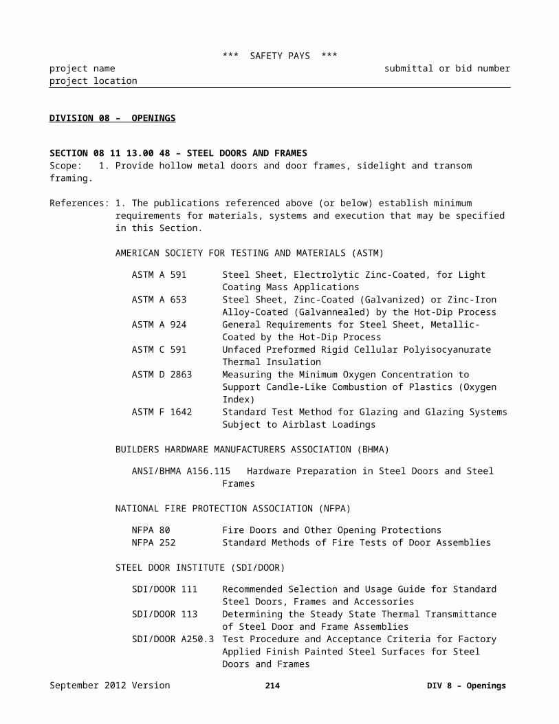
*** SAFETY PAYS ***project name submittal or bid numberproject location
without backing or facing. The cork sheet shall have a tensile strength of not less than 40 psi when tested in accordance with ASTM F 152.
3. Aluminum: Aluminum frame extrusions shall be alloy 6063-T5 or 6063-T6, conform to ASTM B 221 , and be a minimum 0.06 inches thick. Exposed aluminum shall have an anodized, satin finish. Straight, single lengths shall be used wherever possible. Joints shall be kept to a minimum. Corners shall be mitered and shall have a hairline closure.
4. Glass: Glass shall be comprised of tempered glass in accordance with ANSI Z97.1 and shall conform to ASTM C 1048, Kind FT (fully tempered), Condition A (uncoated), Type I, Class I (clear), thickness as specified.
5. Markerboard: Markerboard shall have a porcelain enamel writing surface and a chalktray. Markerboard shall be a factory assembled unit complete in one piece, without joints whenever possible. When markerboard dimensions require delivery in separate sections, components shall be prefit at the factory, disassembled for delivery and jointed at the site. Frame shall be aluminum. Chalktray shall be the same material as the frame and extend the full length of the liquid markerboard. The markerboard shall have a heavy duty map rail with map hooks and clips for holding sheets of paper, end stops, and a tackable insert as specified below and shall extend the full length of the liquid chalkboard. Dry erase markings shall be removable with a felt eraser or dry cloth without ghosting. Each unit shall come complete with an eraser and four different color compatible dry erase markers. The size finish and color shall be as selected by the Architect and accepted by the Government.
6. Continuous Map Rail: Heavy duty aluminum frame continuous Map Rail shall be 2 inch wide and have a tackable insert and shall extend the full length of the rail, and shall have map hooks with clips for holding sheets of paper and end stops. One map hook shall be provided for each 12 inches of map rail. The size shall be as indicated.
5. Tackboards: Tackboards shall consist of a minimum 1/4 inch thick natural cork laminated to a minimum 1/4 inch thick hardboard, and shall have an aluminum frame. The size shall be as indicated.
6. Bulletin Boards: Bulletin boards shall have a hardwood or aluminum frame, 1/4 inch thick plywood or hardboard back; and a 1/4 inch thick, dense, smooth faced corkboard face securely cemented to the back and 1/4 inch tempered glass sliding doors. Glass shall be as specified above.
SECTION 10 12 00.00 48 – RECESSED DISPLAY CASEScope: 1. Provide recessed display case..
Warranty: 1. Include coverage of fabric surface from discoloration due to fading.
Product: 1. Recessed case: Recessed illuminated case with aluminum front with satin anodized finish and a cork back panel. Both units shall have ¼ inch tempered glass sliding doors with finger pulls, locks and keys, shelf brackets, shelf standard and three 12 inch wide adjustable ¼ inch tempered glass shelves. Size shall be as indicated.
2 Required items:a. Wood box of 24 inches in depth. Exposed wood shall be stained light oak.b. Glass: All glass shall be tempered.c. Back Panel: For polyester fabric over cork.d. Trim: Trim shall be satin anodized aluminum.
September 2012 Version 214 DIV 10 – Specialities
*** SAFETY PAYS ***project name submittal or bid numberproject location
SECTION 10 14 01.00 48 – EXTERIOR SIGNAGEScope: 1. Dimensional Building letters and plaques.
References: 1 The publications referenced above (or below) establish minimum requirements for materials, systems and execution that may be specified in this Section.
AMERICAN SOCIETY FOR TESTING AND MATERIALS (ASTM)
ASTM A 36Carbon Structural SteelASTM A 123 Zinc (Hot-Dip Galvanized) Coatings on Iron and Steel ProductsASTM A 570 Steel, Sheet and Strip, Carbon, Hot-Rolled, Structural QualityASTM A 653 Steel Sheet, Zinc-Coated (Galvanized) or Zinc-Iron Alloy-Coated
(Galvannealed) by the Hot-Dip ProcessASTM A 924 General Requirements for Steel Sheet, Metallic-Coated by the Hot-Dip
ProcessASTM B 26 Aluminum-Alloy Sand CastingsASTM B 108 Aluminum-Alloy Permanent Mold CastingsASTM B 209 Aluminum and Aluminum-Alloy Sheet and Plate (Metric)ASTM B 221 Aluminum and Aluminum-Alloy Extruded Bars, Rods, Wire, Profiles, and
Tubes (Metric)
AMERICAN WELDING SOCIETY (AWS)
AWS C1.1M/C1.1 Recommended Practices for Resistance WeldingAWS D1.1 Structural Welding Code - SteelAWS D1.2 Structural Welding Code - Aluminum
Warranty: 1. Manufacturer's standard performance guarantees or warranties that extend beyond a one year period shall be provided.
Products: 1. Modular Exterior Signage System: Exterior signage shall consist of a system of coordinated directional, identification, and regulatory type signs located where shown. Dimensions, details, materials, message content, and design of signage shall be as shown.
2. Metal Plaques: Plaques shall be United States Army Center Reserve Minuteman aluminum plaque: Provided by the Government and installed by the Contractor location of plaques shall be as shown or as directed.
3. Dimensional Building Lettersa. Fabrication: Letters shall be fabricated from cast bronze or cast aluminum. Letters shall be cleaned by
chemical etching or cleaned ultrasonically in a special degreasing bath. Letters shall be packaged for protection until installation.
b. Typeface: Typeface shall be Helvetica medium.c. Size; Letter size shall be as indicated.d. Finish: Polished bronze or with clear coat finish shall be provided.e. Mounting: Threaded studs of number and size as recommended by manufacturer, shall be used for
concealed anchorage. Letters which project from the building line shall have stud spacer sleeves. Letters, studs, and sleeves shall be of the same material. Templates for mounting shall be supplied.
4. Aluminum Alloy Products: Aluminum alloy products shall conform to ASTM B 209 for sheet or plate, ASTM B 221 for extrusions and ASTM B 26 or ASTM B 108 for castings. Aluminum extrusions shall be provided at least 1/8 inch thick and aluminum plate or sheet at least 16 gauge thick. Welding for aluminum products shall conform to AWS C1.1M/C1.1.
September 2012 Version 215 DIV 10 – Specialities

*** SAFETY PAYS ***project name submittal or bid numberproject location
5. Steel Products: Structural steel products shall conform to ASTM A 36. Sheet and strip steel products shall conform to ASTM A 570. Welding for steel products shall conform to AWS D1.2.
6. Cast Bronze: Components shall be fabricated with sharp corners, flat faces, and accurate profiles. Burrs and rough spots shall be removed and polished. Faces shall be finished to a uniform high luster. Cast bronze shall be in accordance with ASTM B 62.
7. Shop Fabrication And Manufacturea. Factory Workmanship: Work shall be assembled in the shop, as far as practical, ready for installation
at the site. Work that cannot be shop assembled shall be given a trial fit in the shop to ensure proper field assembly. Holes for bolts and screws shall be drilled or punched. Drilling and punching shall produce clean, true lines and surfaces. Welding to or on structural steel shall be in accordance with AWS D1.1. Welding shall be continuous along the entire area of contact. Exposed welds shall be ground smooth. Exposed surfaces of work shall have a smooth finish and exposed riveting shall be flush. Fastenings shall be concealed where practical. Items specified to be galvanized shall be by hot-dip process after fabrication if practical. Galvanization shall be in accordance with ASTM A 123 and ASTM A 653, as applicable. Other metallic coatings of steel sheet shall be in accordance with ASTM A 924. Joints exposed to the weather shall be formed to exclude water. Drainage and weep holes shall be included as required to prevent condensation buildup.
b. Dissimilar Materials: Where dissimilar metals are in contact, or where aluminum is in contact with concrete, mortar, masonry, wet or pressure-treated wood, or absorptive materials subject to wetting, the surfaces shall be protected with a coat of asphalt varnish or a coat of zinc-molybdate primer to prevent galvanic or corrosive action.
c. Shop Painting: Surfaces of miscellaneous metal work, except nonferrous metal, corrosion resisting steel, and zinc-coated work, shall be given one coat of zinc-molybdate primer or an approved rust-resisting treatment and metallic primer in accordance with manufacturer's standard practice. Surfaces of items to be embedded in concrete shall not be painted. Upon completion of work, damaged surfaces shall be recoated.
8. Color, Finish, And Contrast: For buildings required to be handicapped-accessible, the characters and background of signs shall be eggshell, matte, or other non-glare finish. Characters and symbols shall contrast with their background - either light characters on a dark background or dark characters on a light background.
SECTION 10 14 02.00 48 – INTERIOR SIGNAGEScope: 1. Provide specialty building directory, and interior signage.
References 1. The publications referenced above (or below) establish minimum requirements for materials, systems and execution that may be specified in this Section.
ALUMINUM ASSOCIATION (AA)
AA DAF-45 Designation System for Aluminum FinishesAA PK-1 Registration Record of Aluminum Association Alloy Designations and
Chemical Composition Limits for Aluminum Alloys in the Form of Castings and Ingot
AMERICAN ARCHITECTURAL MANUFACTURERS ASSOCIATION (AAMA)
AAMA 605 Voluntary Specification, Performance Requirements and Test Procedures for High Performance Organic Coatings on Aluminum Extrusions and Panels
AMERICAN NATIONAL STANDARDS INSTITUTE (ANSI)
ANSI Z97.1 Safety Performance Specifications and Methods of Test for Safety Glazing Materials Used in Buildings
September 2012 Version 216 DIV 10 – Specialities

*** SAFETY PAYS ***project name submittal or bid numberproject location
AMERICAN SOCIETY FOR TESTING AND MATERIALS (ASTM)
ASTM B 209 Aluminum and Aluminum-Alloy Sheet and PlateASTM B 221 Aluminum and Aluminum-Alloy Extruded Bars, Rods, Wire, Profiles, and
TubesASTM C 1036 Flat Glass
AMERICAN WELDING SOCIETY (AWS)
AWS D1.2 Structural Welding Code - Aluminum
NATIONAL FIRE PROTECTION ASSOCIATION (NFPA)
NFPA 70 National Electrical CodeExtra Stock: 1. The Contractor shall provide 5 percent of total extra frames and extra stock of the following: blank plates
of each color and size for each sign type, pressure-sensitive letters in each color and size for each sign type, and changeable message strips for each sign type.
Products: 1. General:a. Interior signage shall be of the design, detail, sizes, types, and message content shown on the drawings,
shall conform to the requirements specified, and shall be provided at the locations indicated. Signs shall be complete with lettering, framing as detailed, and related components for a complete installation. Conform to EPA requirements for recycled materials.
b. Character Proportions and Heights: Letters and numbers on indicated signs in handicapped-accessible buildings, which do not designate permanent rooms or spaces, shall have a width-to-height ratio between 3:5 and 1:1 and a stroke-width-to-height ratio between 1:5 and 1:10. Characters and numbers on indicated signs shall be sized according to the viewing distance from which they are to be read. The minimum height is measured using an upper case letter "X". Lower case characters are permitted. Suspended or projected overhead signs shall have a minimum character height of 3 inches .
c. Raised and Braille Characters and Pictorial Symbol Signs (Pictograms): Letters and numbers on indicated signs which designate permanent rooms and spaces in handicapped-accessible buildings shall be raised 1/32 inch upper case, sans serif or simple serif type and shall be accompanied with Grade 2 Braille. Raised characters shall be at least 5/8 inch in height, but no higher than 2 inches. Pictograms shall be accompanied by the equivalent verbal description placed directly below the pictogram. The border dimension of the pictogram shall be 6 inch minimum in height. Indicated accessible facilities shall use the international symbol of accessibility.
2. Manufacturers:
ASI Sign Systems, Inc.3890 W Northwest HueyDallas, TX 75220800-ASI-SPEC
Interface International5320 Webb ParkwayLilburn, Georgia 30247404-921-5566
Apco Graphics388 Grant Street SEAtlanta, Georgia 30312404-688-9000
UNICOR Systems 2/90September 2012 Version 217 DIV 10 – Specialities

*** SAFETY PAYS ***project name submittal or bid numberproject location
244 West Como AvenueColumbus, Ohio 43202800-777-4310
3. Room Identification/Directional Signage System:a. Holder: Integrally colored injection molded high impact plastic complete with mounting system, ready
for insert installation. Corners of signs shall be rounded. Wall mounting shall be double sided tape for wall mounting and Velcro or manufacturers' recommended factory applied mating strips for attachment to System Furniture. Size as indicated at the end of this section. Color: As selected.
b. Changeable Message Strip Signs: Changeable message strip signs shall consist of injection molded high impact plastic . Size of signs shall be as at the end of this section. Corners of signs shall be rounded to match frame.
c. Mounting Inserts To Holder: Double side vinyl foam tape when mounting is permanent, when inserts are subject to frequent change use 1/32 inch thick magnetic tape. Color: as selected.
d. Provide the following options indicated in the Schedule at end of this section:Split insertsHangable slide insertsWindow sign insert module.Window sign.
e. Graphics: Signage graphics for modular identification/directional signs shall conform to the following:1) Message shall be applied to panel using the silkscreen process. Silkscreened images shall be
executed with photo screens prepared from original art. Handcut screens will not be accepted. Original art shall be defined as artwork that is a first generation reproduction of the specified art. Edges and corners shall be clean.
f. Graphics Application: Message content is specified in the Sign Schedule at the end of this section; Verify message with the Government. Typeface shall be Helvetica Medium, size as indicated. Background color shall be as selected.
4. Building Directories: Building directories shall be lobby directories surface mounted, non-illuminated, wall hung, with message strips. Where required, message content shall be as shown on drawings and schedule.a. Header Format: Header format shall be Helvetica Medium, uppercase. Imprint color.b. Door Glazing: Door glazing shall be clear acrylic sheet.c. Door Construction: Extruded aluminum door frame shall be of same finish as surrounding frame.
Corners shall be mitered and assembled with concealed fasteners. Hinges shall be concealed continuous stainless steel, in natural anodized aluminum finish . Glazing shall be set in frame with resilient glazing channels.
d. Door Locks: Door locks shall be manufacturer's standard, and shall be keyed alike.e. Fabrication: Extruded aluminum frames and trim shall be ASTM B 221, 6063-T5 extruded aluminum
alloy frame surrounding solid backing plate with PVC laminated to solid backing, provide holes in back plate. Finish and color shall be anodized aluminum as selected by the Architect and accepted by the Government.
f. Message Strips: Message strips shall be injection molded plastic with digital computer generated and photo silk screened typography; provide sufficient strips to fill directory, up-datable by user with book reordering and with 7 to 10 day delivery. Type style shall be Helvetica Medium, size shall be3/4 inch initial caps. Provide strips with self aligning reveal and flex and stack ability for ease of installation and removal. Imprint color as selected.
g. Directory Capacity: Capacity shall be as follows:Number of sides: [one] [ ]Number of message strips per column: [21] [ ]Number of Columns: [Two] [ ].
SECTION 10 21 13.00 48 – PLASTIC TOILET PARTITIONSScope: 1. Provide toilet partitions and screens; Floor-supported partitions.
2. Solid Plastic Shower compartment Benches.
September 2012 Version 218 DIV 10 – Specialities
*** SAFETY PAYS ***project name submittal or bid numberproject location
References: 1. The publications referenced above (or below) establish minimum requirements for materials, systems and execution that may be specified in this Section.
COMMERCIAL ITEM DESCRIPTIONS (CID)
CID A-A-60003 Partitions, Toilet, CompleteWarranty: 1. Manufacturer's standard performance guarantees or warranties that extend beyond a 1 year period shall be
provided.
Regulatory requirements:1. Comply with SECTION 01 62 35 - RECYCLED / RECOVERED MATERIALS requirements for recycled
content.. Where possible, product shall be purchased locally to reduce emissions of fossil fuels from transporting. Shower and Restroom Dividers/Partitions to have the following minimum recycled content: a. Plastic: 20% Postconsumer Content and Total Recovered Materials Content
Products: 1. Toilet Enclosures: Toilet enclosures shall conform to CID A-A-60003, Type I, Style A, Solid Polyethylene, Finish 5, floor supported. Width, length, and height of toilet enclosures shall be as shown. Finish surface of panels shall be solid plastic with 20 percent or more recovered plastic. Panels indicated to receive toilet paper holders or grab bars as specified in Section 10 28 13.00 48 TOILET ACCESSORIES, shall be prepared for mounting of the items required. Grab bars shall withstand a bending stress, shear stress, shear force, and a tensile force induced by 250 lbf. Grab bars shall not rotate within their fittings. Pilaster shoes shall be as standard with the manufacturer. Doors shall be 2’-0” wide except the handicap stall shall have a 3'-0" wide door. Color shall be as selected by the Architect and accepted by the Government
2. Urinal Screens: Urinal screens shall conform to CID A-A-60003, Type III, Solid Polyethylene, Finish 5, wall mounted. Finish surface of screens shall be solid plastic with 20 percent or more recovered plastic. Width and height of urinal screens shall be as shown. Color shall be as selected by the Architect and accepted by the Government.
3. Hardware: Hardware for the toilet partition system shall conform to CID A-A-60003 for the specified type and style of partitions. Hardware finish shall be satin stainless steel No. 4 finish and highly resistant to alkalis, urine, and other common toilet room acids. Doors shall be furnished with a stainless steel coat hook and door bumper. Doors shall have thumb turn door latch with exterior emergency access feature and door stiles with latch keeper/stop and rubber bumper. Out-swinging door shall have a door pull and shall be ADA compliant.
SECTION 10 22 13.00 48 – WIRE MESH PARTITIONSScope: 1. Provide wire mesh partitions for storage, stockroom, and security separations.
References: 1. The publications referenced above (or below) establish minimum requirements for materials, systems and execution that may be specified in this Section..
AMERICAN IRON AND STEEL INSTITUTE (AISI)
AISI SG- 973 Cold-Formed Steel Design Manual
ASTM INTERNATIONAL (ASTM)
ASTM A 36/A 36M Carbon Structural Steel
Product manufacturers:Wire Crafters800.626.1816Louisville, Ky.
September 2012 Version 219 DIV 10 – Specialities

*** SAFETY PAYS ***project name submittal or bid numberproject location
www.wirecrafters.com
California Wire Products Corp.Corona, CA 951.735.1070www.cawire.com
Spaceguard ProductsSeymour, IN800.841.0680www.spaceguardproducts.com
Alabama MetalsBirmingham, Ala205.787.2611
W.A.SchmidtSounderton, PA800.523.6719
2. Product Data.
3. Shop Drawings.
Products: 1. Steel Shapes, Plates, and Bars ASTM A 36/A 36M.
2. Cold-Formed Steel of AISI SG-973.
3. Wire Mesh: Carbon steel wire, welded or woven 1” x 2” mesh, intermediate crimped. (Welded not allowed in arms vault)
4. Floor Sockets: Cast or forged steel or ductile iron, adjustable, approximately 2 1/2 inches high.
5. Heavy Duty Partitions:a. Wire Mesh, 10 gage wire, 1" x 2" mesh.b. Vertical Frames, 2" x 2" x 14 gauge steel tube frame.c. Horizontal Frames, 1 1/4" x 1 1/4" x 1/8" steel angle frames.d. Structural steel angles, 2" by 2" by 14 gauge.e. Hinged Doors, frames shall be 1 1/4" by 1 1/4" by 3/16" angle with 2" x 1" 10 gauge rectangular steel
mesh. Provide high and low lugs for padlocks on each door and frame. Provide spring loaded hinges. Provide two horizontal and one vertical flat stiffener of 1/4" by 3/4" steel. Provide two gate posts and hardware. Provide stiffeners in door panel to prevent twisting action and allow unauthorized access into the caged area. Stiffeners should secure both corners of the swinging door opposite the hinge side
f. Door Frames, provide frames the same size and shape as the vertical frames for the mesh panels.g. Locks, provide each door with twin lugs or holes in steel for padlock application.h. Fabrication, standard panels of wire shall be 10 gauge 2" by 1" mesh opening, 1 1/4" by 1 1/4" by 1/8"
steel angle. All ceiling panels are non-load bearing.i. Finish, thoroughly clean ferrous metal, treat with phosphate, and paint with one coat of shop applied
acrylic enamel.
Installation: 1. Wire Mesh Partitions, install plumb, level, and true to line, within a tolerance of 1/8 inch in 10 feet or the height or run of the partition, if less than 10 feet. Anchor floor baseplate to the floor with expansion anchors. Tamperproof fasteners shall be used at all bolted connections. Tamperproof fasteners shall be manufactured products designed to be nonremovable. The use of welded, peened, deformed, or damaged bolted connections is not allowed.
September 2012 Version 220 DIV 10 – Specialities

*** SAFETY PAYS ***project name submittal or bid numberproject location
September 2012 Version 221 DIV 10 – Specialities
*** SAFETY PAYS ***project name submittal or bid numberproject location
SECTION 10 22 26.00 48 – OPERABLE PARTITIONSScope: 1. Provide operable partitions.
References: 1. The publications referenced above (or below) establish minimum requirements for materials, systems and execution that may be specified in this Section.
AMERICAN SOCIETY FOR TESTING AND MATERIALS (ASTM)
ASTM E 84 Surface Burning Characteristics of Building MaterialsASTM E 90 Laboratory Measurement of Airborne Sound Transmission Loss of Building
PartitionsASTM E 413 Rating Sound Insulation
Submittals: 1. Shop Drawings: Drawings containing complete schematic diagrams and details required to demonstrate that the system has been coordinated and will properly function as a unit. Drawings shall show proposed layout and anchorage of equipment and appurtenances, and equipment relationship to other parts of the work including clearances for maintenance and operation.
Warranty: 1. Manufacturer's standard performance guarantees or warranties that extend beyond a 1 year period shall be provided.
Products: 1. General Requirements:a. The Contractor shall supply and install flat wall, manual operation,, paired panels, center stacking, top
supported, acoustical operable partitions as shown on the drawings including all hardware, seals, track and rollers as needed to close the specified opening. The panel shall have a minimum Sound Transmission Coefficient (STC)of 48 measured in accordance with ASTM E 90. The partition shall be made up of a series of rigid, flat wall panels; each panel being a one-piece assembly nominally 48 inches wide. Unless otherwise specified, the wall shall comprise the least number of panels. The mechanical seal of the panel shall actuate with a single operating action.
b. The manual operation shall be accomplished with less than 200 ft/min force to start movement at the rate of 3.33 ft/s. A removable handle shall be used to extend and retract the bottom operable seals; vertical movement of seals shall be 2 inches. Closure to the lead wall shall be by use of a flexible bulb; final closing shall be accomplished by means of a lever exerting pressure against wall.
2. Material and equipment shall be the standard products of a manufacturer regularly engaged in the manufacture of such products and shall essentially duplicate items that have been in satisfactory use for at least 2 year prior to bid opening. Equipment shall be supported by a service organization that is, in the opinion of the Government, reasonably convenient to the site. Door and partition finishes shall have a Class A rating when tested in accordance with ASTM E 84.a. Panel Surface Finish: Panel surface finish shall be an acoustically absorbent “wall carpet” or an acrylic
backed, vinyl wall covering, Class A, Fire Resistive Grade according to ASTM E 84, 24 ga. thick, bacterial resistant. Panel surface finish and color shall be as selected from manufacturer’s standard offering, no COM will be acceptable. .
b. Hardware: Operable partitions shall have manufacturer's standard hardware. Latching door handles shall be chrome plated, hinges shall be stainless steel.
c. Sweep Strips: Sweep strips shall be vinyl or other material which will not crack or craze with severe usage. Sweep strip shall control STC to the specified rating.
d. Track: Track shall be recessed and shall be of extruded aluminum or enamel finish steel. Track shall be manufacturer's standard product designed for the weight of the finished partition. Track sections shall be provided in the maximum lengths practicable and secured to structure with threaded rods. Suitable joint devices such as interlocking keys shall be provided at each joint to provide permanent alignment of track.
e. Metal Soffit: Soffit shall be provided when steel track is recessed. Soffit shall be of metal of adequate thickness to protect the ceiling from damage by door operation and shall be provided with the door
September 2012 Version 222 DIV 10 – Specialities

*** SAFETY PAYS ***project name submittal or bid numberproject location
manufacturer's standard neutral-color applied finish. Soffit on aluminum track shall be an integral part of the track.
f. Vinyl Restrictions: Vinyls shall contain a non-mercury based mildewcide and shall be manufactured without the use of cadmium-based stabilizers.
3. Operable Partitions: Operable partitions shall consist of top hung ball bearing carriers which support paired modular panels. Partition finish shall have a flame spread rating of not more than 25 in accordance with ASTM E 84.a. Panels: Panels shall be constructed of minimum 16 gauge thick steel frames with minimum 22 gauge
thick face panels spot welded to the frame. Panels shall be not more than 48 inches wide, except for end closure panels, and shall be full height to track. Panels shall lock in place to form a stable, rigid partition; low profile hinges shall project 1/4 inch maximum from panel edge. Panel thickness shall be minimum (3 1/2 inch nominal) and composition shall be designed to provide an STC rating of not less than 48 in accordance with ASTM E 90 and ASTM E 413.
b. Seals: Top and bottom seals shall consist of a vinyl sweep mechanical seal which will expand in place or shall be accomplished by using panels which can be lowered by a removable operating device. Vertical seal between panels shall be anodized, architectural grade, aluminum extrusion with vinyl sound seal.
c. For operable partition that do not have automatic seals Contractor shall provide 3 removable operating devices for each operable partition indicated on the drawings.
SECTION 10 26 00.00 48 – WALL AND CORNER GUARDSScope: 1. Provide wall and corner guards:
References: 1. The publications referenced above (or below) establish minimum requirements for materials, systems and execution that may be specified in this Section.
ALUMINUM ASSOCIATION (AA)
AA DAF-45 Designation System for Aluminum Finishes
AMERICAN SOCIETY FOR TESTING AND MATERIALS (ASTM)
ASTM A 167 Stainless and Heat-Resisting Chromium-Nickel Steel Plate, Sheet, and StripASTM B 221 Aluminum and Aluminum-Alloy Extruded Bars, Rods, Wire, Profiles, and
TubesASTM D 256 Determining the Izod Pendulum Impact Resistance of PlasticsASTM D 635 Rate of Burning and/or Extent and Time of Burning of Self-Supporting
Plastics in a Horizontal PositionASTM E 84 Surface Burning Characteristics of Building Materials
NATIONAL ASSOCIATION OF ARCHITECTURAL METAL MANUFACTURERS (NAAMM)
NAAMM AMP 500 Manual Metal Finishes Manual for Architectural and Metal Products
SOCIETY OF AUTOMOTIVE ENGINEERS INTERNATIONAL (SAE)
SAE J 1545 Instrumental Color Difference Measurement for Exterior Finishes, Textiles and Color Trim
Warranty: 1. Manufacturer's standard performance guarantees or warranties that extend beyond a 1 year period shall be provided.
Products: 1. To the maximum extent possible, corner guards, and wall guards (bumper guards) shall be the standard products of a single manufacturer and shall be furnished as detailed. Drawings show general configuration of products required, and items differing in minor details from those shown will be acceptable.
September 2012 Version 223 DIV 10 – Specialities

*** SAFETY PAYS ***project name submittal or bid numberproject location
2. Resilient Material: Resilient material shall consist of high impact resistant extruded acrylic vinyl, polyvinyl chloride, or injection molded thermal plastic and shall conform to the following:a. Minimum Impact Resistance: Minimum impact resistance shall be 18 ft. lb/sq. inch when tested in
accordance with ASTM D 256, (Izod impact, ft. lbs per sq inch notched).b. Fire Rating: Fire rating shall be Class 1 when tested in accordance with ASTM E 84, having a
maximum flame spread of 25 and a smoke developed rating of 450 or less. Material shall be rated self extinguishing when tested in accordance with ASTM D 635. Material shall be labeled and tested by an approved nationally known testing laboratory. Resilient material used for protection on fire rated doors and frames shall be listed by the testing laboratory performing the tests. Resilient material installed on fire rated wood/steel door and frame assemblies shall have been tested on similar type assemblies. Test results of material tested on any other combination of door/frame assembly will not be acceptable.
c. Integral Color: Colored components shall have integral color and shall be matched in accordance with SAE J 1545 to within plus or minus 1.0 on the CIE-LCH scales.
3. Corner Guards:a. Resilient Corner Guards: Corner guard units shall be surface mounted type, radius formed to profile
shown. Corner guards shall be [as indicated on the drawings] [extend from floor to ceiling] [be inches high]. Mounting hardware, cushions, and base plates shall be furnished. Assembly shall consist of a snap-on corner guard formed from high impact resistant resilient material, minimum 0.078 inch thick, mounted on a continuous aluminum retainer. Extruded aluminum retainer shall conform to ASTM B 221, alloy 6063, temper T5 or T6. Flush mounted type guards shall act as a stop for adjacent wall finish material. Factory fabricated end closure caps shall be furnished for top and bottom of surface mounted corner guards. Flush mounted corner guards installed in fire rated wall shall maintain the rating of the wall. Insulating materials that are an integral part of the corner guard system shall be provided by the manufacturer of the corner guard system. Exposed metal portions of fire rated assemblies shall have a paintable surface.
b. Stainless Steel Corner Guards: Stainless steel corner guards shall be fabricated of 0.0625 inch thick material conforming to ASTM A 167, type 302 or 304. Corner guards shall be [as indicated on the drawings] [extend from floor to ceiling] [be inches high]. Corner guard shall be formed to dimensions shown.
4. Wall Guards, Combination Handrail/Wall Guards and Handrails: Wall guards, combination handrail/wall guards, and handrails shall; consist of snap-on covers of high impact resistant resilient material on a continuous, extruded aluminum retainer and shall be provided with prefabricated end closure caps, inside and outside corners, concealed splices, cushions, mounting hardware and other accessories standard with the manufacturer. Extruded aluminum retainers shall conform to ASTM B 221, alloy 6063, temper T5 or T6. End caps and corners shall be field adjustable to assure close alignment with handrails and wall guards. Wall guard profile shall be as indicated on D/B construction drawings.
5. Trim, fasteners and anchors: Vinyl trim, fasteners and anchors shall be provided for each specific installation as shown.
6. Finish:a. Aluminum Finish: Finish for aluminum shall be in accordance with AA DAF-45. Exposed aluminum
shall be designation AA-C22A31 chemically etched medium matte, with clear anodic coating class II architectural coating 0.010 mm thick. Concealed aluminum shall be mill finish.
b. Stainless Steel Finish: Finish for stainless steel shall be in accordance with NAAMM AMP 500 Manual, finish number 4.
c. Resilient Material Finish: Finish for resilient material shall be pebble grain texture with colors in accordance with SAE J 1545.
7. Color: Color, texture and pattern shall be as selected by the Architect and accepted by the Government
SECTION 10 28 00.00 48 – TOILET ACCESSORIES
September 2012 Version 224 DIV 10 – Specialities
*** SAFETY PAYS ***project name submittal or bid numberproject location
Scope: 1. Provide toilet accessories at toilet and locker rooms.
References: 1. The publications referenced above (or below) establish minimum requirements for materials, systems and execution that may be specified in this Section.
AMERICAN NATIONAL STANDARDS INSTITUTE (ANSI)
ANSI A117.1 Safety Standards for the Handicapped.
AMERICAN SOCIETY FOR TESTING MATERIALS (ASTM)
ASTM A123 Zinc (Hot-Dip Galvanized) Coatings on Iron and Steel Products.ASTM A167 Stainless and Heat-Resisting Chromium-Nickel Steel Plate, Sheet, and Strip.ASTM A269 Seamless and Welded Austenitic Stainless Steel Tubing for General Service.ASTM A366 Steel, Carbon, Cold-Rolled Sheet, Commercial Quality.
Product M:
Bobrick Washroom Equipment, Inc.;Bradley Corporation;American Specialties;
Regulatory Requirements:1. Conform to ANSI A117.1 code for access for the handicapped.
Products: 1. Manufactured Units: Toilet accessories shall be provided where indicated in accordance with Schedule below. Each accessory item shall be complete with the necessary corrosion resistant mounting plates.
a. Anchors and fasteners shall be capable of developing a restraining force commensurate with the strength of the accessory to be mounted and shall be suited for use with the supporting construction. Exposed fasteners shall [have oval heads] [be of tamperproof design] and shall be finished to match the accessory.
b. Stainless Steel Sheet: ASTM A167, Type 304.c. Adhesive: Two component epoxy type waterproof.d. Fasteners, Screws, and Bolts: Hot dip galvanized, tamper-proof, and security type.e.f. Expansion Shields: Fiber, lead, or rubber as recommended by accessory manufacturer for component
and substrate.2. Keying: Supply 2 keys for each accessory.
3. Finishes: a. Galvanizing: ASTM A123 to 42.36g/sq. m. Galvanize ferrous metal and fastening devices. b. Shop Primed Ferrous Metals: Pretreat and clean, spray apply one coat primer and bake.c. Stainless Steel: All metal appearance finishes shall be No. 4 satin luster finish, unless otherwise
noted.
4. Back paint components where contact is made with building finishes to prevent electrolysis.
September 2012 Version 225 DIV 10 – Specialities

*** SAFETY PAYS ***project name submittal or bid numberproject location
Schedule: A1, Mop and Broom Holder: ASI (1315-6), Bobrick (B-224), Bradley (9986) - Strip shall be constructed of 1.31mm (18 gage) Type 302 stainless steel no. 4 satin finish. Strip shall be formed with a return flange to the wall on top and a returned flange to the wall at the bottom. Holder pieces shall be constructed from molded resilient rubber with ribbed gripping surface. Strip shall be 1200mm (36-inches) long with 6 holders.
A2, Stainless Steel Framed Mirror: ASI (0600), Bobrick (2908), Bradley (780) - Mirror, 460 x 760mm: (18 x 30 inches), shall be framed with one-piece, type 304, stainless steel angle, 19 x 19mm with continuous integral stiffener on all sides and beveled edge to hold frame tightly against mirror. Corners shall be heliarc welded, ground and polished smooth. All exposed surfaces shall be satin finish. Mirror shall be No. 1 quality 6mm (1/4-inch) tempered glass. All edges shall be protected by high impact plastic filler strips. Back of mirror shall be protected by shock- absorbing, waterproof, non-abrasive 6.4mm thick polystyrene padding. Galvanized steel back shall have integral hanging brackets for mounting on concealed rectangular wall hanger(s) and be secured with concealed Phillips-head locking screws in lower frame.
A3, Tilted Mirror: ASI (0535), Bobrick (B-293-1830), Bradley (740) - Sloping tilt mirror frame, 460 x 760mm (18 x 30 inches), shall be type 304 stainless steel with beveled front to hold frame tightly against mirror. Corners shall be heliarc welded, ground, and polished smooth. All exposed surfaces shall have satin finish with vertical grain. Mirror shall be 6.4mm tempered glass. All edges shall be protected by full-size, shock-absorbing, water-resistant, nonabrasive polystyrene padding. Back and inner stiffener frame shall be galvanized steel, one piece welded construction with slots for mounting screws and integral screw-head lock.
A4, Recessed Paper Towel Dispenser and Waste Receptacle: ASI (9467), Bobrick (B-3803), Bradley (2027-10) - Recessed paper towel dispenser and waste receptacle shall be type 304 stainless steel with all welded construction; exposed surfaces shall have satin finish. Door shall be 18 gage and secured to the cabinet with a concealed, full length stainless steel piano hinge and equipped with a stainless steel cable door swing limiter and two tumbler locks. Paper towel dispenser shall be capable of dispensing 600 C fold, 800 multi-fold or 1100 single-fold paper towels. Waste receptacle shall be furnished with a removable, leakproof rigid molded plastic waste container with a capacity of 24 liters (6.3 gal).
A5, Recessed Paper Towel Dispenser and Waste Receptacle ASI (0462 ADL), Bobrick (B-369), Bradley (2291-10), - Recessed paper towel dispenser and waste receptacle shall be constructed entirely of Type 304 stainless steel, welded construction with exposed surfaces satin finish. Flange shall be drawn one-piece seamless construction. Door shall be double pan construction and equipped with a knob latch. Door shall be secured to cabinet with full-length stainless steel piano hinge. Paper Towel Dispenser shall be capable of dispensing 350 fold or 475 Multifold paper towels without use of adapters. Waste receptacle, removable for servicing, with top edges hemmed for safe handling, shall have a capacity of minimum 7.57 liters (2-gal). Recessed depth shall be maximum 100mm.
A6 and A7, Partition Mounted Double Toilet Tissue Dispenser with Toilet Seat Dispenser and Feminine Napkin Disposal For Servicing Two Toilet Compartments: (A6) ASI (0481), Bobrick (B-357), Bradley (591) and (A7) ASI (0481-HC), Bobrick (B-3571), Bradley (5911) - Partition mounted double roll toilet tissue dispenser each side shall be type 304 stainless steel with all welded construction. Exposed surfaces shall have satin finish. Toilet seat dispenser shall hold up to 1000 single or half folded toilet seat covers. Front of door shall be drawn, one piece, seamless construction. Toilet seat dispenser door shall be secured to cabinet with piano hinge equipped with a flush tumbler lock. Unit shall dispense two standard core toilet tissue rolls up to 133mm (5 1/4") in diameter on each side. Unit shall include four heavy duty, one-piece molded polyethylene spindles. Dual feminine napkin disposal shall be constructed entirely of type 302 stainless steel. Sanitary napkin dispenser door shall be secured to cabinet with a spring loaded, full length stainless steel piano hinge and equipped with international graphic symbol. Unit A7 has one side flush with the face of the toilet partition to allow for grab bar clearance.
September 2012 Version 226 DIV 10 – Specialities

*** SAFETY PAYS ***project name submittal or bid numberproject location
A8, Recessed Double Toilet Tissue Dispenser with Toilet Seat Dispenser and Feminine Napkin Disposal: ASI (04833), Bobrick (B-35704), Bradley (5942). Recessed double roll toilet tissue dispenser shall be type 304 stainless steel with all welded construction. Exposed surfaces shall have satin finish. Toilet seat dispenser shall hold up to 1000 single or half-folded toilet seat covers. Front of door shall be drawn, one piece, seamless construction. Toilet seat dispenser door shall be secured to cabinet with piano hinge equipped with a flush tumbler lock. Sanitary napkin dispenser door shall be secured to cabinet with a spring loaded, full-length stainless steel piano hinge and equipped with international graphic symbol. Unit shall dispense two standard core toilet tissue rolls up to 133.4mm in diameter. Unit shall include two heavy-duty, one-piece molded polyethylene spindles.
A8-b, Recessed Toilet-Seat-Cover Dispenser, Sanitary Napkin Disposal, And Toilet Tissue Dispenser: (Bobrick B-3574) Unit shall be type 304, 22 gauge, stainless steel all welded construction, exposed surfaces shall have a satin finish. Front of door shall be drawn, one piece, seamless construction. Toilet seat dispenser door shall be secured to cabinet with piano hinge equipped with a flush tumbler lock. Unit shall dispense two standard core toilet tissue rolls up to 5.25 inches in diameter on each side. Unit shall include two heavy duty, one-piece molded polyethylene spindles. Sanitary napkin disposal shall be furnished with a removable,, leak proof, molded polyethylene receptacle with a capacity of .75 gal. Toilet seat dispenser shall hold up to 1000 single or half -folded toilet seat covers.
A9 and A10, Partition Mounted Double Toilet Tissue Dispenser with Toilet Seat Dispenser For Servicing Two Toilet Compartments: ASI (0484), Bobrick (B-347), Bradley (592) and (A10) ASI (0484-HC), Bobrick (3471), Bradley (5921) - Partition mounted double roll toilet tissue dispenser each side shall be type 304 stainless steel with all welded construction. Exposed surfaces shall have satin finish. Toilet seat dispenser shall hold up to 1000 single or half-folded toilet seat covers. Front of door shall be drawn, one piece, seamless construction. Toilet seat dispenser door shall be secured to cabinet with piano hinge equipped with a flush tumbler lock. Unit shall dispense two standard core toilet tissue rolls up to 133mm (5 1/4") in diameter on each side. Unit shall include four heavy duty, one-piece molded polyethylene spindles. Unit A10 has one side flush with the face of the toilet partition to allow for grab bar clearance.
A11, Recessed Double Toilet Tissue dispenser with Toilet Seat Dispenser: ASI (0486), Bobrick (B-3474), Bradley (5922) - Recessed double roll toilet tissue dispenser shall be type 304 stainless steel with all welded construction. All exposed surfaces shall have a satin finish. Toilet seat dispenser shall hold 500 paper covers. Door shall be one-piece seamless construction secured to cabinet with a full-length stainless steel piano hinge, and equipped with a tumbler lock. Unit shall dispense two standard core toilet tissue rolls up to 135mm in diameter. Unit shall include two one-piece molded polyethylene spindles.
A11-b, Surface Mounted Multi-Roll Toilet Tissue Dispenser: (ASI Model No. 0021, Bradley Model No. 5402, Bobrick Model No. B-4288) -Surface-Mounted Multi-Roll Toilet Dispenser shall be type 304 stainless steel with all welded construction. All exposed surfaces shall have a satin finish. Door shall be one piece seamless construction secured to cabinet and equipped with a tumbler lock. Unit shall automatically drop in place when bottom roll is depleted. Unit shall include two one-piece molded polyethylene spindles.
A11-c, Surface-Mounted Napkin Disposal and Dual Roll Toilet Tissue Dispenser: (ASI Model No. 04833, Bradley Model No. 5942-11, Bobrick Model No. B-35709) - Surface Mounted Napkin Disposal and Dual Roll Toilet Tissue Dispenser and sanitary napkin disposal shall be type 304 stainless steel with all welded construction. Exposed surfaces shall have satin finish. Front door shall be drawn, one-piece, seamless construction, secured to cabinet with piano hinge equipped with a flush tumbler lock. Self closing disposal panel shall be secured to cabinet with a spring loaded, full -length stainless steel piano hinge and napkin disposal shall be furnished with a removable, leak proof, molded polyethylene receptacle with a capacity of 1 gal. Unit shall include two heavy-duty, one-piece molded polyethylene spindles.
September 2012 Version 227 DIV 10 – Specialities

*** SAFETY PAYS ***project name submittal or bid numberproject location
A12, Surface-Mounted Soap Dispenser with Shelf: ASI (0315), Bobrick (B-2014), Bradley (662) - Soap vessel and shelf are satin-finish stainless steel. Valve shall be corrosion resistant design. Soap container shall be removal and have a capacity of 2.4L (80 fl oz) with unbreakable refill window. Adequate adjustments/accessories shall be provided to allow dispenser to work in location indicated in the drawings.
A12-b, Lavatory-Mounted Soap Dispenser: (Bradley Model No. 6324, Bobrick Model B-82216)- Lavatory Mounted Soap Dispenser shall dispense liquid and lotion soaps, and synthetic detergents. Value shall be operable with one hand and with less than 5 lbs. of force to comply with barrier free accessibility. Piston and spout assembly shall be type 304 stainless steel with bright polished finish. Escutcheon shall lock to body with concealed locking mechanism that is opened only with special key provided. Spout shall rotate 360 degrees without damage to valve mechanism. Piston, spout and supply tube assembly shall be removable from top for filling and maintenance. Valve shall be equipped with plastic cylinder, stainless steel spring, U-packing seal and duckbills. Shank shall accommodate mounting thickness up to 1 inch Translucent, shatter resistant polyethylene container shall have a capacity of 20 oz.
A12-c, Surface - Mounted Soap dispenser For Liquid And Soaps And Detergents: (Bobrick Model B-2112) Surface Mounted Soap Dispenser shall be constructed entirely of type 304, stainless steel with exposed surfaces satin finish. Valve shall dispense liquid and lotion soaps and synthetic detergents. Valve shall be operable with one hand and with less than 5 pounds of force. Container shall be equipped with a clear acrylic soap refill-indicator window; a locked, hinged stainless steel lid for top filling; and shall have a capacity of 40 fl. oz. Unit shall have a concealed, vandal resistant mounting.
A13, Stainless Steel Utility Hook: ASI (7340), Bobrick (B-670), Bradley (9115) - Utility Hook shall be constructed entirely of type 304 stainless steel with satin finish. Flange and support arm shall be 22 gauge and equipped with a concealed, 1/16 in mounting bracket secured to a 1/16 inch wall plate with a stainless steel set screw. Hook shall be .11 inch welded to support arm. Fastenings and mounting plates shall be concealed.
A14, Stainless Steel Grab Bars With Concealed Mounting: ASI (3201-01-36), Bobrick (B-5806-36), Bradley (812-001-36) - Grab bar shall be constructed of type 304 stainless steel with satin finish. It shall have wall thickness of 1.31mm (18 gage) and outside diameter of 38mm (1 1/2-inches). Distance from inside of grab bar to finished wall shall be 38mm (1 1/2-inches). Flanges shall be 3.13mm (11-gage) stainless steel, 75mm (3-inch) diameter and each shall have 4 stainless steel set screws. Ends of grab bar shall pass thru flanges and be heliarc welded to form one structural unit. Flange covers shall be 22 gauge., 3 3/8" in diameter, and 1/2 in deep and shall snap over mounting flange to conceal mounting screws. grab bar shall comply with ADAAG guidelines for structural strength. Concealed mounting plates shall be 2.37mm (13-gage) stainless steel with 3 slotted screw holes.
A15, Recessed Soap Holder and Bar: ASI (7410 and 7410D), Bobrick (B-438 and B-4390), Bradley (940 and 9402) - Unit shall be constructed of type 304 stainless steel with satin finish. Soap dish and flange shall be drawn and beveled, one-piece seamless construction. Unit shall include a bar constructed of 4.8mm (3/16-inch) thick matching stainless steel. Recess depth shall be maximum 75mm.
A16, Heavy-Duty Shower Curtain Rod with Concealed Mounting: ASI (1214), Bobrick (B-207), Bradley (9539) - Unit shall be of type 304 stainless steel, 1.006mm (20-gage), with satin finish. Outside diameter shall be 25.4mm (1-inch). Flanges shall be 80mm (3 3/16-inch) maximum diameter with satin finish. Unit shall include concealed mounting brackets.
A17, Stainless Steel Curtain Hook:: ASI (1200-SHU), Bobrick (B-204-1), Bradley (9536) - Shower curtain hooks shall type 304 stainless steel. Hooks shall be usable with curtain rod specified for Item A15. Hooks shall snap open to allow placement on curtain rod.
September 2012 Version 228 DIV 10 – Specialities

*** SAFETY PAYS ***project name submittal or bid numberproject location
A18, Opaque White Vinyl Shower Curtain: ASI (1200-V), Bobrick (B-204-3), Bradley (9537) - Shower curtain shall be opaque, matte white vinyl. Curtain shall include rust-proof grommets along top, one at every 150mm (6")intervals. Bottom and sides shall be hemmed. Curtain shall be 1830mm (72") high and 1778mm (70") wide.
A19, Double-coin Recessed Napkin/Tampon Vendor: ASI (0464), Bobrick (B-3500), Bradley (401) - Recessed napkin/tampon vendor shall combine two dispensing mechanisms in one cabinet to provide napkins or tampons at user's option. Dispensing mechanisms shall be convertible to allow the change of coin denomination without purchasing new mechanisms or removing unit from wall. Unit shall be type 304 stainless steel with all-welded construction. Cabinet shall be .85mm (22 gage). Door shall be 1.31mm (18 gage); exposed surfaces shall have satin stainless steel finish. Door shall have 22.2mm (7/8") 90 degree return edges; be secured to cabinet with a concealed, full-length, stainless steel piano-hinge; and equipped with a stainless steel cable doorstop and two tumbler locks. Recessed depth shall be maximum 165mm (6-1/2"). Each coin box shall be equipped with a tumbler lock that is keyed differently than door locks. Unit shall carry no brand-name advertising. Unit shall be equipped with double-coin mechanisms in the amount to be determined by the Government.
A19-b, Surface-Mounted Napkin / Tampon Vendor: (ASI Model 0864, Bradley Model 426, Bobrick Model B-2800) Recessed sanitary napkin / tampon vendor shall combine two dispensing mechanism in one cabinet to provide sanitary napkin or tampon at user's option. Dispensing mechanism shall be pre-set for 25 cent operation, but shall convert able in the field to allow the change of coin denomination without purchasing new mechanism or removing unit for the wall. Door shall be furnished with metal plates indicating specified coin denomination. Unit shall be type 304 stainless steel all welded construction. Exposed surfaces shall be satin finish. Flanges shall be drawn, one-piece, seamless construction; secured to cabinet with a full length, stainless steel piano hinge. Door shall be equipped with steel door swing limiter and concealed tumbler lock. Pull knobs shall be operable with one hand and with less than 5 lbs. of force. Each coin box shall be equipped with a tumbler lock that is keyed differently than door locks. Units shall not carry brand name advertising.
A20, Recessed Multipurpose Unit with Mirror, Paper Towel Dispenser, Shelf, and Soap Dispenser: ASI (0430), Bobrick (B-330), Bradley (130) - Recessed-mounted multipurpose unit shall incorporate mirror, paper towel dispenser, shelf and soap dispenser. Unit shall be type 304 stainless steel all welded construction. Exposed surfaces shall be satin finish. Mirror shall be mounted to the door secured to cabinet with a full length, stainless steel piano hinge. Door shall be equipped with a steel door swing limiter and concealed tumbler lock. Paper towel dispenser shall dispense 600 C fold or 800 multifold paper towels. Soap valve shall be operable with one hand and with less than 22.2N of force. Soap vessel shall slide out for easy refilling and have a capacity of 2.5L (80 fl oz).
A21, Stainless Steel Frame Mirror (Full Length): ASI (0600), Bobrick (B-290), Bradley (780) - Angle framed mirror,: 1830mm x 915mm (72" x 36"), shall be stainless steel with a satin finish. Mirror shall be No.1 quality, 6mm (1/4-inch) select float glass selected for silvering, electrolytically copper-plated by the galvanic process, and guaranteed for 15 years against silver spoilage. All edges protected by plastic filler strips. Back is protected by full-size, shock-absorbing, water-resistant, nonabrasive, 5mm (3/16-inch) thick polyethylene padding.
A21-b, Stainless Steel Framed Mirror: (Bobrick Model 290, - Mirror, (24 x 72 inches), shall be framed with one-piece, type 304, stainless steel angle, 3/4 by 3/4 inch with continuous integral stiffener on all sides and beveled edge to hold frame tightly against mirror. Corners shall be heliarc welded, ground and polished smooth. All exposed surfaces shall be satin finish. Mirror shall be No. 1 quality 1/4 - inch tempered glass. All edges shall be protected by high impact plastic filer strips. Back of mirror shall be protected by shock absorbing, waterproof, non-abrasive 1/4 inch thick polystyrene padding. Galvanized steel back shall have integral hanging brackets for mounting on concealed rectangular wall hangar(s) and be secured with concealed Phillips-head locking screws in lower frame.
A21-c, Surface Mounted Multipurpose Unit With Mirror, Paper Towel Dispenser, Self and Soap Dispenser: (Bobrick model B-3309) Surface Mounted Multipurpose Unit shall incorporate mirror, paper towel dispenser, shelf, and soap dispenser. Unit shall be type 304, stainless steel all welded construction; exposed surfaces shall have a satin finish. Mirror shall be No.1 quality. 1/4 inch thick select float glass, copper plated. Polished edges shall be fully protected. Mirror shall have a 15-year guarantee against silver spoilage and shall be mounted in the door secured to the cabinet with a full length stainless steel piano hinge. Door
September 2012 Version 229 DIV 10 – Specialities

*** SAFETY PAYS ***project name submittal or bid numberproject location
shall be equipped with a stainless steel swing limiter and concealed tumbler lock. Paper towel dispenser shall have a rounded opening with hemmed edges and shall dispense 600 C fold or 800 multifold paper towels. Soap vessel shall be type 304, stainless steel with satin finish. Unlocked with a special key provided and slides out for filling. Soap dispenser shall have an unbreakable polycarbonate refill indicator window, be vandal resistant and have a capacity of 5 pints. Soap valve shall be operable with one hand and with less than 5 lbs. of force to comply with ADAAG barrier free accessibility guidelines. Corrosion resistant valve shall dispense liquid soaps, and detergents.
A22, Surface Mounted Roll-Paper-Towel Dispenser: ASI (2482-11), Bobrick (B-2860), Bradley (8522) - Surface mounted, roll paper towel dispenser. Push-bar or lever-handle operated. Stainless steel cabinet. Dispenses one standard core 205mm or 230mm(8" or 9") wide, up to 244M (800 feet) long.
A22-b, Surface Mounted Paper Towel Dispenser and Waste Receptacle: (ASI Model 0467 SM, Bradley Model 234-11, Bobrick Model No. B-43949)- Surface Mounted Paper Towel Dispenser and Waste Receptacle shall be constructed entirely of Type 304, 22 gauge. Stainless steel, welded construction with exposed surfaces satin finish. Flange shall be drawn one-piece seamless construction. Door shall be secured double pan construction and equipped with a knob latch. Door shall be secured to cabinet with full stainless steel piano hinge. Paper Towel Dispenser shall be capable of dispensing 600 C-fold or 800 Multifold paper towels without use of adapters. Waste receptacle shall have a formed, one-piece, seamless removable front panel with top edge hemmed and shall be equipped with interior clips for securing furnished reusable vinyl liner. Waste receptacle shall have capacity of minimum 16 gal.
A22-c, Surface Mounted Roll-Paper Towel Dispenser And Receptacle: (Bobrick Model B-39619) Roll Paper Towel Dispenser shall be constructed of type 304 stainless steel with all welded construction. Exposed surfaces shall have satin finish. Door shall be secured to cabinet with a full length stainless steel piano hinge and equipped with a tumbler lock. Dispenser shall deliver a preset length of towel per stroke of lever and shall accept standard core rolls 8 inches wide. Unit shall accept stub rolls together with a new roll. When stub is used up, new roll shall automatically start to dispense. Dispenser lever shall be operable with one hand, without tight grasping, pinching, or twisting of the wrist and with less than 5 lbs. of force to comply with barrier free accessibility guidelines. waste receptacle shall be type 304, stainless steel with satin finish with edges hemmed and shall be equipped with interior clips for securing furnished reusable vinyl liner. Waste receptacle shall be secure to cabinet with a tumbler lock and have a capacity of minimum 12 gal.
A22-d, Surface-Mounted Paper Towel Dispenser: (Bobrick Model B-262) Surface mounted paper towel dispenser shall be constructed entirely of type 304, stainless steel, welded construction with exposed surfaces satin finish. Towel tray shall have an hemmed opening. Door shall be doubled pan construction and equipped with a tumbler lock. Door shall be secured to cabinet with full length stainless steel piano hinge. Paper towel Dispenser shall be capable of dispensing 400 C-fold or 525 Multifold paper towels without using adapters.
A22-e, Surface Mounted Waste Receptacle: (ASI Model 0825, Bobrick Model B-275) Waste Receptacle shall be type 304, 22 gauge, stainless steel all welded construction, exposed surfaces shall have satin finish. Waste receptacle shall be equipped with 4 interior hooks, have reinforced mounting screws, and shall be furnished with a heavy-gauge vinyl liner. Unit shall have a capacity of 20 gal.
A23, Folding Shower Seat: (ASI Model 82101 & 8210R, Bradley Model 956, 9961, Bobrick Model B-5181) Reversible shower seat shall have a frame constructed of type 304, satin finish stainless steel, that consists of square tubing and seamless tubing. Seat shall be one-piece, solid phenolic with matte finish, ivory colored, melamine surfaces, and black phenolic-resin core; secured to frame with stainless steel carriage bolts and acorn nuts. Seats shall be reversible or shall accommodate right or left seating. Shower seats shall be equipped with two mounting flanges constructed of type 304 satin finish stainless steel; a guide bracket constructed of type 304, satin finish stainless steel; and a spring constructed of type 301, stainless steel spot welded to a baseplate of type 304 heavy-gauge stainless steel. Seat shall remain in upright position when not in use. Shower seat shall comply with ADAAG barrier free guidelines.
September 2012 Version 230 DIV 10 – Specialities

*** SAFETY PAYS ***project name submittal or bid numberproject location
A23-b, Solid Phenolic Folding Shower Seat: Bobrick Model B-5191) Folding Shower Seat shall have a frame constructed of type 304, satin finish stainless steel, that consists of square tubing and seamless tubing. Seat shall be one-piece, solid phenolic laminate with matte finish, ivory colored, melamine surfaces, and black phenolic-resin core; secured to frame with stainless steel carriage bolts and acorn huts. Shower seats shall be equipped with two mounting flanges constructed of type 304, satin finish stainless steel,; a guide bracket constructed of type 304, satin finish stainless steel; and a spring constructed of type 301, stainless steel spot welded to a baseplate of type 304 heavy gauge stainless steel. Seat shall remain in upright position when not in use. Shower seat shall comply with ADAAG barrier free guidelines.
A24, Surface Mounted Toilet Seat Cover: (Bobrick Model No.B-3803) Surface mounted toilet seat cover shall
be type 304, 20 gauge stainless steel with drawn , one piece, seamless construction; exposed surface shall have satin finish. Unit shall have a rectangular or oval opening for dispensing toilet seat covers and a concealed opening in bottom for filling. Capacity shall be 250 paper toilet seat covers.
SECTION 10 44 00.00 48 – FIRE EXTINGUISHERS, CABINETS AND ACCESSORIESScope: 1. Provide portable fire extinguishers and cabinets. Provide mounting brackets where no cabinet is indicated.
References: 1. The publications referenced above (or below) establish minimum requirements for materials, systems and execution that may be specified in this Section.
AMERICAN NATIONAL STANDARDS INSTITUTE (ANSI)
ANSI/NFPA 10 Portable Fire Extinguishers.ANSI/UL 711 Rating and Fire Testing of Fire Extinguishers.
Product Manufacturers:
Fire Extinguisher Cabinets (FEC)
FEC: J. L. Industries;4450 W. 78th St. CircleBloomington, MN 55435,952-835-6850
FEC: Larsen's Manufacturing Company;7421 Commerce Lane N.E.Minneapolis, MN800-527-7367
FEC: Potler-Roemer;16833 Edwards Rd.,Cerritos, CA 90701-2417310-404-3753
2. Shop Drawings: Indicate cabinet physical dimensions, rough-in measurements for recessed cabinets, and location.
Coordination: 1. Fire extinguishers shall also be provided. Fire extinguisher shall be 20 lb size minimum and shall meet NFPA 10 requirements. Coordinate size of cabinet and extinguisher. Coordinate installation of fire extinguishers prior to contract completion. Coordinate the exact location of cabinet with other work.
Quality Assurance: 1. Provide units conforming with ANSI/UL 711.
Regulatory Requirements: 1. Conform to ANSI/NFPA 10 for requirements for extinguishers.
September 2012 Version 231 DIV 10 – Specialities
*** SAFETY PAYS ***project name submittal or bid numberproject location
Products: 1. Fire extinguishers: Fire extinguishers shall also be provided. Fire extinguisher shall be 20 lb ABC Dry Chemical fire extinguisher minimum and shall meet NFPA 10 requirements. Contractor shall determine type of extinguishers required. Coordinate size of cabinet and extinguisher. Coordinate installation of fire extinguishers prior to contract completion. Coordinate the exact location of cabinet with other work.
2. Cabinets: Trimless recessed or semi-recessed steel cabinet with baked enamel finish. Steel door shall be red baked solid type, 30 gage with white silk screened words: "Fire Extinguisher" arranged vertically. Cabinet shall be sized to accommodate a 20 lb ABC Dry Chemical fire extinguisher.
SECTION 10 50 00.00 48 – METAL LOCKERS (OMAR FUNDED)Scope: 1. Provide single and double tier metal lockers and bench seat.
References: 1. The publications referenced above (or below) establish minimum requirements for materials, systems and execution that may be specified in this Section.
AMERICAN SOCIETY FOR TESTING AND MATERIALS (ASTM)
ASTM A653 Standard Specification for Steel Sheet, Zinc-Coated (Galvanized) or Zinc Iron Alloy Coated (Galvanized) by the Hot-Dip Process
Products: 1. Sheet Steel: ASTM A653 Grade D, Coating Designation G90, stretcher leveled; to the following minimum thicknesses:a. Body and Shelf: 24 gageb. Door Outer Face: 16 gagec. Door Inner Face: 20 gaged. Door Frame: 16 gagee. Hinges: 14 gagef. Base: 20 gageg. Sloping Top: 20 gageh. Trim: 20 gage
2 Single Tiered Locker: Size shall be a minimum 12 inches wide, 15 inches deep, 72 inches high (Dust covers around the entire perimeter of the base will increase height by 6 inches to 78 inches.) Provide dust covers with sloped tops and end covers to preclude dust accumulation. End panels as required per drawing configuration. Maximum size of grouping units is three lockers per unit. Latch hook to have bevel on front upper edge to allow latch clip to ride up slope as door closes. Steel door frames of minimum 16 gauge metal with three hinges of minimum 14 gauge steel. Vertical members shall have an additional flange to form continuous door strike. Minimum gauge for top, bottom, shelves, sides, back and row ends of 24 gauge steel. Eyelet for padlock must accept a 5/16 inch padlock shank, providing a secured locking three point latching mechanism. Lockers will be sequentially numbered with a plate beginning with #1. Locker will contain a single shelf at top and wall hooks on both sides. Louvers for circulation both at top and bottom. Lockers are to be installed in the room with dust covers installed. Color shall be as selected by the Architect and accepted by the Government
3 Double Tiered Locker: Size shall be a minimum 12 inches wide, 15 inches deep, 36 inches high, 72 inches over all (Dust covers around the entire perimeter of the base will increase height by 6 inches to 78 inches.) Provide dust covers with sloped tops and end covers to preclude dust accumulation. End panels as required per drawing configuration. Maximum size of grouping units is three lockers per unit. Latch hook to have bevel on front upper edge to allow latch clip to ride up slope as door closes. Steel door frames of minimum 16 gauge metal with three hinges of minimum 14 gauge steel. Vertical members shall have an additional flange to form continuous door strike. Minimum gauge for top, bottom, shelves, sides, back and row ends of 24 gauge steel. Eyelet for padlock must accept a 5/16 inch padlock shank, providing a secured locking three point latching mechanism. Lockers will be sequentially numbered with a plate beginning with #1. Locker will contain a single shelf at top and wall hooks on both sides. Louvers for circulation both at top
September 2012 Version 232 DIV 10 – Specialities
*** SAFETY PAYS ***project name submittal or bid numberproject location
and bottom. Lockers are to be installed in the room with dust covers installed. Color shall be as selected by the Architect and accepted by the Government
4. Locker Benches: Stationary free standing type; bench top of laminated maple species wood, stained, sealed and varnished; pedestals of chrome steel 17 1/2 inches high.
Fabrication: 1. Locker Unit:a. Mounting: Surface mounted and free standing.b. Base: Metal base, 4 inches high.c. Top: Sloped metal with closures.d. Locking: Equipped for built-in with master key cylinder locks.e. Ventilation Method: Louvered top and bottom frame and top and bottom of door.
SECTION 10 55 00.00 48 – POSTAL SPECIALTIESScope: 1. Provide postal specialties acceptable to postal authorities.
Products: 1. Mailboxes: Mailboxes shall be U.S. Postal Service approved. Mailboxes, materials, sizes, construction, and installation shall comply with U.S. Postal Service regulations and shall be fully approved by the U.S. Postal Service.a. Materials: Quantities and arrangement of mailboxes shall be as indicated on the drawings. Mailboxes
shall be rear-loading type with sheet aluminum removable rear covers strengthened with formed sheet aluminum stiffeners. Framework supporting compartment doors shall be fabricated from high strength extruded aluminum alloy. Compartment doors shall be fabricated from high strength extruded aluminum alloy, with a minimum of 1/8 inch thickness, and swing on concealed hinge pins. When closed, the door shall interlock with frame member along hinge side and shall be precision fitted to preclude prying. Doors shall be reinforced vertically along both sides and near center with integral ribs. Locks on individual compartment doors shall be springlatch type lock actuated by a cam type lock with two change keys per lock and a minimum of 1000 available key changes. All locks within project shall be keyed differently. Compartment construction shall be double-walled high strength sheet aluminum alloy with vertical stiffeners of formed aluminum. Finish shall be as indicated. Mail box manufacturer shall furnish aluminum channel type card holders with pressure sensitive backing to accommodate 7/16 inch by 2 1/2 inch cards for individual and/or unit names.
SECTION 10 56 13.00 48 – STORAGE SHELVING (OMAR FUNDED)Scope: 1. Metal Storage Shelving.Quality Assurance: 1. Manufacturer Qualifications: Firm (material producer) with not less than 3 years of production
experience, whose published literature clearly indicates general compliance of products with requirements of this section.
2. Installer Qualifications: Firm specializing in metal storage shelving installation with not less than 2 years of experience in installation of metal storage shelving and pallet racks similar to that required for this project.
3. Single Source Responsibility: Provide material produced by a single manufacturer for each shelving unit type.
Warranty: 1. Special Project Warranty: Submit a written warranty, executed by the Contractor, Installer and the Manufacturer, agreeing to repair or replace shelving units which fail in materials or workmanship within the specified warranty period. This warranty shall be in addition to and not a limitation of other rights the Government may have against the Contractor under the Contract Documents. Warranty period is 2 years after the date of Substantial Completion.
Maintenance: 1. Maintenance Instructions: Submit manufacturer's printed instructions for maintenance of installed work, including methods and frequency recommended for maintaining optimum condition under anticipated use conditions. Include precautions against materials and methods which may be detrimental to finishes and performance.
September 2012 Version 233 DIV 10 – Specialities

*** SAFETY PAYS ***project name submittal or bid numberproject location
2. Replacement Materials: After completion of work, deliver not less than 2 of each type, color, and pattern of metal storage shelving, exclusive of material required to properly complete installation. Furnish 2% of accessory components as scheduled. Furnish replacement materials from same production run as materials installed. Package replacement materials with protective covering, identified with appropriate labels.
Products: 1. Product M:
Penco Products Inc.;99 Brower AvenueP. O. Box 378Oaks, PA 19456-0378800.562.1000 www.pencoproducts.com
Republic Storage Systems Co., Inc.;1038 Beldon Avenue, NECanton, OH 44705800.477.1255www.republicstorage
2. Metal Storage Shelves:a. General: Minimum 20 gauge cold-rolled steel sheet metal, washed to receive powder coated baked
enamel finish, higher gauge where indicated to provide appropriate loading capacity. Shelving shall meet the requirements of ANSI MH28.1.
b. Open Shelving: Provide extra heavy-duty (Penco Class 2), 900 pound capacity open shelving units consisting of four upright corner pilasters, slotted to receive clips clipped together with shelves as indicated. Provide cross-braces laterally and at ends as required for stability with intended load. Shelves adjustable 38 mm on center. Provide 48 inches wide by 87 inches high units, unless otherwise indicated on drawings or in specifications. Provide 5 shelves of standard 24 and 32 inch depth.
c. Lateral Cross Braces: Minimum 12 gauge, 1 inch wide steel band, formed and punched at each end, capable of bolting to T sections. Provide one pair of cross braces for every three sections of under 30 inches; two pairs for every two sections 30 inches and over.
d. Bases: Channel-shaped to engage upright T sections with spring fasteners, minimum 20 gauge for 3 inch base, minimum 18 gauge for 6 inch base.
e. Finish: Provide units in finishes and colors from manufacturer's standard grey.
SECTION 10 75 00.00 48 – FLAGPOLESScope: 1. Provide Ground mounted flagpole systems.
References: 1. The publications referenced above (or below) establish minimum requirements for materials, systems and execution that may be specified in this Section.
AMERICAN ASSOCIATION OF STATE HIGHWAY AND TRANSPORTATION OFFICIALS (AASHTO)
AASHTO M-36 Corrugated Metal Culvert Pipe.
AMERICAN SOCIETY FOR TESTING AND MATERIALS (ASTM)
ASTM B241 Aluminum and Aluminum-Alloy Seamless Pipe and Seamless Extruded Tube.
Product Manufactures:
September 2012 Version 234 DIV 10 – Specialities

*** SAFETY PAYS ***project name submittal or bid numberproject location
Flagpole: American Flagpole,800.368.7171www.americanflagpole.com
Flagpole: Ewing Flagpoles., Inc.;2316 Delaware Avenue #283Buffalo, NY 14216800.663.7653
Flagpole: Concord Industries, Inc.4150-A Kellway CircleP. O. Box 1163Addison, Texas 75001800.527.3902www.flagpoles.com
2. Shop Drawings: Indicate detailed dimensions, base attachment details, anchor requirements, and imposed loads.
3. Samples: Submit two samples 4” x 4” in size illustrating pole material, color, and finish.
Products: 1. Aluminum: ASTM B241, 6063 alloy, T6 temper.
2. Pole Configuration: Ground Mounted, tapered shaft, internal halyard with winch.
3 Components And Accessories:a. Finial Ball: Stainless steel, 3” diameter.b. Truck Assembly: Cast aluminum revolving, stainless steel ball bearings, non-fouling.c. Flag: provided by othersd. Winch: An internal winch operated by a removable handcrank. The winch contains an automatic brake
system to permit locking of the flag in any position.e. Winch Box: Aluminum, with built-in hinge and lock assembly, attached to pole with tamper proof
screws inside box. Provide two keys to operate the lock.f. Halyard: Stainless steel aircraft cable with two chrome plated bronze swivel snaphooks, plastic
covered counterweight and beaded sling.g. Primer: As recommended by the flagpole manufacturer.
4. Mounting Components: Foundation to be sized based on local conditions.a. Foundation Tube Sleeve: AASHTO M-36, corrugated 16 gage steel, galvanized, depth as
recommended by the flagpole manufacturer.b. Pole Base Attachment: Flush aluminum base with base cover.c. Lighting Ground Rod: 12 inch long copper rod, 0.188 inch diameter.d. Lightning Ground Cable: Copper No. 6 AWG, soft drawn.
5. Finishes: Selection to be made from manufacturer's standard.
September 2012 Version 235 DIV 10 – Specialities
*** SAFETY PAYS ***project name submittal or bid numberproject location
DIVISION 11 – EQUIPMENT
SECTION 11 13 00.00 48 – LOADING DOCK EQUIPMENTScope: 1. Provide commercial and industrial loading dock equipment.
Submittals: 1. Shop Drawings: Truck Levelers; Drawings with complete wiring, schematic diagrams, and any other details required to demonstrate that the system has been coordinated and will properly function as a unit. Detail drawings shall show proposed layout and anchorage of equipment and appurtenances. Detail drawings shall show; method of mounting and anchoring; and location of control stations and disconnect switches.
2. Product Data: Truck Levelers; Data including a complete list of equipment and materials, manufacturer's descriptive and technical literature, performance charts and curves, catalog cuts, and installation instructions.
Warranty: 1. Provide manufacturers 10 year warranty.
Products: 1. Surface Mounted Truck Leveler: 10 ft x 16 ft, 60,000 lb capacity and a 48 inch lift, Model TL-216 as manufactured by Advanced Lifts, Inc. or equal
2. Dock Bumpers shall be high impact resistant molded or laminated rubber with angles and rods, hot dipped galvanized (ASTM A123).a. Width: 4 inch.b. Vertical Height:12 inch.c. Length:18 inch.
3. Attachment Hardware: Galvanized bolts and expansion shields.
4. Touch-up Primer: Organic zinc paint, minimum 70 percent solids content.
SECTION 11 30 00.00 48 – RESIDENTIAL EQUIPMENT (OMAR FUNDED)Scope: 1. Provide refrigerator and microwaves at break rooms.
2. Provide undercounter refrigerator at Family Support room.
References: 1. The publications referenced above (or below) establish minimum requirements for materials, systems and execution that may be specified in this Section.
NATIONAL FIRE PROTECTION ASSOCIATION (NFPA)
NFPA 70 National Electrical Code
UNDERWRITERS LABORATORIES (UL)
UL 250 Household Refrigerators and FreezersUL 923 Microwave Cooking Appliances
Products: 1. Refrigerator: UL 250, refrigerator with frostproof top freezer, minimum 20 cubic feet, automatic defrosting, two vegetable bottom baskets, four adjustable shelves, two door shelves and minimum 12 egg container in the door, separate interior shelves, multiple door shelves, and door mounted ice and water dispenser. For refrigerator with top freezer, provide reversible (left swing and right swing interchangeable) doors. Provide four fixed rollers or adjustable leg levelers. Refrigerator shall be white.
2. Microwave Oven: UL 923, with black glass window door, minimum 1.5 cubic feet capacity, automatic oven light, browning element, 10 power levels, automatic temperature controllers, minimum two automatic memory levels, digital time controllers, and electronic touch-control panel. Microwave shall be white.
September 2012 Version 236 DIV 11 – Equipment

*** SAFETY PAYS ***project name submittal or bid numberproject location
3. Undercounter Refrigerator: UL approved, undercounter refrigerator with manual defrost top freezer, minimum 4.3 cubic feet total, 0.5 cubic foot top freezer, two adjustable shelves, separate interior shelves, multiple door shelves. Provide four fixed rollers or adjustable leg levelers. Refrigerator shall be white
Execution: 1. Installation: Install kitchen equipment in accordance with manufacturers' instructions and NFPA 70.
SECTION 11 46 01.00 48 – FOOD SERVICE EQUIPMENT (OMAR FUNDED)Scope: 1. Food service equipment shall be of the sizes and types shown. Equipment, materials, and fixtures required
for use in conjunction with the items to be furnished by the Government shall be furnished and installed by the Contractor. Equipment, materials, and fixtures indicated on the drawings and schedules shown as Contractor furnished and installed, shall be furnished and installed by the Contractor. Cut sheets are specified in an appendix of Section 01 02 00 STATEMENT OF WORK.
2. Mechanical, Electrical, Air-conditioning systems and Plumbing Work, Gas and Steam piping, and Ductwork, including final connections, shall be in accordance with Division 23 HEATING, VENTILATING, AND AIR CONDITIONING . Electrical equipment, motors, wiring, and final connections shall be in accordance with Division 26 - ELECTRICAL. Painting shall be in accordance with 09 90 00.00 48 PAINTS AND COATINGS.
3. Kitchen Fire Protection Systems: Each exhaust hood system that serves cooking equipment, associated exhaust hood system ducts, and all cooking equipment served by the exhaust hood system shall be protected with a wet chemical fire extinguishing system. The wet chemical fire extinguishing systems shall be in accordance with Section 21 21 03.00 48 WET CHEMICAL FIRE EXTINGUISHING SYSTEM. Grease extracting type hoods that have an internal hood fire protection system do not require wet chemical fire extinguishing protection for those components of the exhaust system, and for cooking equipment protected by a UL listed internal hood fire protection system complying to NFPA 96.
4. National Sanitation Foundation Standards: Food service equipment shall meet the requirements set forth by the National Sanitation Foundation (NSF). Acceptable evidence of meeting the requirements of the applicable NSF standards shall be either the equipment listed in NSF-01 displaying the NSF seal for the year the equipment was manufactured, a certification issued for special or specific food service equipment by NSF under their special one time contract evaluation and certification, or a certified test report from an independent testing laboratory, approved by the Office of the Surgeon General, indicating that the specific food service equipment has been tested and conforms to the applicable NSF standards.
5. Verification of Dimensions and Coordination of Project Data: The Contractor shall become familiar with all details of the work and shall advise the Government of any discrepancy before performing any work. The Contractor shall perform the following:a. Horizontal and vertical dimensions shall be field verified.b. Contract drawings and submittal data shall be reviewed for accuracy and completeness.c. The installed utility capacity and location shall be field checked.d. Critical systems/components shall be reviewed for application and capacities such as for exhaust
hoods, refrigeration systems, fire suppression systems, gas, water, and steam/condensate line sizes and manifold configurations.
e. Delivery shall be coordinated for access through finished openings and vertical handling limitation within the building.
6. Standard Products: Materials and equipment shall be the standard products of manufacturer regularly engaged in the manufacture of the products and shall essentially duplicate items that have been in satisfactory use for at least 2 years prior to bid opening. The experience used shall include applications of equipment and materials under similar circumstances and of similar size. When two or more of the same products are supplied they shall be products of one manufacturer. Equipment shall be supported by a service organization that is, in the opinion of the Government, reasonably convenient to the site.
September 2012 Version 237 DIV 11 – Equipment

*** SAFETY PAYS ***project name submittal or bid numberproject location
7. Nameplates: Each item of equipment shall bear a stainless steel, aluminum, or engraved polyester nameplate, as standard with the manufacturer, located in a conspicuous position and permanently fastened to the equipment. Name or identification plates shall be of the size standard with the manufacturer for the particular piece of equipment provided. Name plates shall reflect the name of the manufacturer/trade name, serial number, make, and model number, pertinent ratings, operating characteristics, and other information as standard with the manufacturer, date of manufacture, electrical characteristics, and other applicable data, such as flow rate, temperature, pressure, capacity, and material of construction. Separate equipment identification plates with the contract number marked thereon, shall be securely fastened to the surface of each piece of equipment.
8. American Gas Association Laboratories Standards: Gas-burning equipment shall be designed for operation with the type of gas specified and shall be approved by AGAL. Acceptable evidence of meeting the requirements of the applicable AGAL Directory standards shall be either AGAL mark on equipment, a photostatic copy of the AGAL appliance certificate, a listing of the specific food service equipment or appliance in the AGAL Directory of Certified Appliances and Accessories, or a certified test report from a nationally recognized independent testing laboratory, indicating that the specified equipment has been tested and conforms to the requirements of the applicable AGAL standards.
9. Underwriters Laboratories Standards: Electrically operated equipment shall be in accordance with applicable UL standards such as UL 471, UL 489, UL 710 and UL 197. Evidence of meeting the requirements shall be a UL label on the equipment, a UL listing mark per UL Elec Equip Dir or a certified test report from a nationally recognized independent testing laboratory indicating that the specific food service equipment has been tested and conforms to the applicable UL standards.
References: 1. The publications referenced above (or below) establish minimum requirements for materials, systems and execution that may be specified in this Section.
AMERICAN CONFERENCE OF GOVERNMENTAL INDUSTRIAL HYGIENISTS (ACGIH)
ACGIH-2092 Industrial Ventilation: A Manual of Recommended Practice (24th edition)
AMERICAN GAS ASSOCIATION LABORATORIES (AGAL)
AGAL Directory Directory of AGA & CGA Certified Appliances and Accessories
AMERICAN SOCIETY FOR TESTING AND MATERIALS (ASTM)
ASTM A 36/A 36M Carbon Structural SteelASTM A 123/A 123M Zinc (Hot-Dip Galvanized) Coatings on Iron and Steel ProductsASTM A 167 Stainless and Heat-Resisting Chromium-Nickel Steel Plate, Sheet, and StripASTM A 240/A 240M Heat-Resisting Chromium and Chromium-Nickel Stainless Steel Plate, Sheet,
and Strip for Pressure VesselsASTM A 269 Seamless and Welded Austenitic Stainless Steel Tubing for General ServiceASTM B 32 Solder MetalASTM D 520 Zinc Dust Pigment
AMERICAN WELDING SOCIETY (AWS)
AWS A5.8 Filler Metals for Brazing and Braze Welding
MANUFACTURERS STANDARDIZATION SOCIETY OF THE VALVE AND FITTINGS INDUSTRY (MSS)
MSS SP-72 Ball Valves with Flanged or Butt-Welding Ends for General ServiceMSS SP-110 Ball Valves Threaded, Socket-Welding, Solder Joint, Grooved and Flared
EndsSeptember 2012 Version 238 DIV 11 – Equipment

*** SAFETY PAYS ***project name submittal or bid numberproject location
NATIONAL ELECTRICAL MANUFACTURERS ASSOCIATION (NEMA)
NEMA 250 Enclosures for Electrical Equipment (1000 Volts Maximum)NEMA ICS 6 Industrial Control and Systems, Enclosures
NATIONAL FIRE PROTECTION ASSOCIATION (NFPA)
NFPA 54 National Fuel Gas CodeNFPA 70 National Electrical CodeNFPA 96 Ventilation Control and Fire Protection of Commercial Cooking Equipment
NSF INTERNATIONAL (NSF)
NSF-01 Listings of Food Equipment and Related Products, Components, and Materials
NSF 2 Food EquipmentNSF 7 Commercial Refrigerators and Storage Freezers
SHEET METAL & AIR CONDITIONING CONTRACTORS' NATIONAL ASSOCIATION (SMACNA)
SMACNA HVAC Duct Const Stds HVAC Duct Construction Standards - Metal and Flexible
UNDERWRITERS LABORATORIES (UL)
UL Electrical Equipment Directory Electrical Appliance and Utilization Equipment DirectoryUL 197 Commercial Electric Cooking AppliancesUL 207 Refrigerant-Containing Components and Accessories, NonelectricalUL 471 Commercial Refrigerators and FreezersUL 489 Molded-Case Circuit Breakers, Molded-Case Switches and Circuit-Breaker
EnclosuresUL 710 Exhaust Hoods for Commercial Cooking EquipmentUL 1046 Grease Filters for Exhaust Ducts
Submittals: 1. Shop Drawings: Data consisting of a complete list of equipment and materials. Detail drawings showing complete wiring, piping, and schematic diagrams, and any other details required to demonstrate that the system has been coordinated and will properly function as a unit. Drawings shall show proposed layout and anchorage of equipment and appurtenances, and equipment relationship to other parts of the work, including clearances for maintenance and operation.a. Detail drawings by Contractor shall be separate drawings and shall be the contractor's standard sheet
size, but not smaller than the contract drawings, and indicate the food service equipment and cold storage assemblies with itemized schedule, and special conditions drawings indicating size and location of slab depressions, cores, wall openings, blockouts, ceiling pockets, blocking grounds, ceiling, and wall, access panels, and above ceiling hanger assemblies, rough-in plumbing/mechanical systems and rough-in electrical systems.
b. Detail drawings by manufacturer shall be separate drawings; sheet size shall be manufacturer's standard size and indicate item number, name, and quantity, construction details, sections, and elevations, adjacent walls, columns, and equipment, plumbing and electrical schematics, and fabricated fixtures with single electrical or plumbing connection, and service access panels required for maintenance or replacement of mechanical or electrical components.
c. Detail drawings by the Contractor that show the size, type, and location of equipment drain lines, and floor drains. Drawings shall indicate drain lines from equipment, distances of drain lines and floor drain receptacles from equipment and aisles, and elevation views of drain piping and floor drains.
2. Product Data: Manufacturer's descriptive and technical literature, performance charts and curves, catalog cuts, and installation instructions. Brochures shall have front and rear protective covers with labeled
September 2012 Version 239 DIV 11 – Equipment
*** SAFETY PAYS ***project name submittal or bid numberproject location
project name and include an index indicating item number, quantity, description, and manufacturer, a fly sheet for each component indicating item number, name, quantity, manufacturer, optional equipment, modification, special instruction, and utility requirements, and catalog specifications sheets.
3. Test Reports: Test reports in booklet format showing all field tests performed to prove compliance with the specified performance criteria, upon completion and testing of the installed system. Each test report shall indicate the final position of controls.
4. Operation and Maintenance Data: Operations and Maintenance Manuals will be submitted in accordance with the requirements of specification Section 01 78 23.00 06 EQUIPMENT OPERATING, MAINTENANCE, AND REPAIR MANUALS. Six complete copies of the service manual, not later than 3 months prior to the date of beneficial occupancy, with data for each different item of material and equipment specified. Service manuals shall include:a. Front and rear protective covers with labeled project name.b. Index indicating item number, quantity, description, manufacturer's name, and model number.c. Maintenance instructions for stainless steel and plastic laminate.d. Manufacturer's catalog specification sheets and manufacturer's detail and control drawings.e. Manufacturer's operation manual outlining the step-by-step procedures for equipment installation,
startup, basic operation features, and operation shutdown.f. Manufacturer's maintenance manual listing routine maintenance procedures, possible breakdowns,
repairs, and troubleshooting guides. The instructions shall include simplified diagrams for the equipment as installed.
g. Manufacturer's list of parts and supplies with current unit price and address of manufacturer's parts supply warehouse.
Products: 1. Materials shall conform to the following:
2. Stainless Steel, Nonmagnetic: ASTM A 167 or ASTM A 240/A 240M: 18-8, 300 Series, austenitic, polished to No. 3 or 4 finish on exposed surfaces.
3. Stainless Steel Pipe and Tubing: ASTM A 269. Pipe and tubing shall be seamless or welded, of the gauge specified, of true roundness, and of material as specified for stainless steel. Seamless tubing shall be thoroughly annealed, pickled, and ground smooth. Welded tubing shall be thoroughly heat-treated, quenched to eliminate carbide precipitation and then drawn true to size and roundness, and ground. Tubing shall be given a No. 3 or 4 finish when exposed to view.
4. Galvanizing Repair Compound: ASTM D 520, Type I pigment
5. Brazing Material: AWS A5.8, class shall be as applicable.
6. Steel Structural Shapes for Framing: ASTM A 36/A 36M. Structural shapes shall be uniform, ductile in quality, and shall be free of hard spots, runs, checks, cracks and other surface defects. Sections shall be galvanized by the hot-dip process, conforming to ASTM A 123/A 123M.
7. Coatings: Coatings shall be of a durable, nontoxic, nondusting, nonflaking, and mildew-resistant type, suitable for use with food service equipment and in conformance with NSF 2. Application shall be in accordance with the recommendations of the manufacturer.
8. Exterior Parts: Exterior, galvanized parts, exposed members of framework, and wrought steel pipe, where specified to be painted, shall be cleaned, and free of foreign matter before applying a rust inhibiting prime and two coats of epoxy-based paint in accordance with Section 09 90 00.00 48 PAINTS AND COATINGS, unless otherwise specified. Color shall be selected by the Government from manufacturer's standard colors.
9. Solder Material: ASTM B 32, Sn96.
September 2012 Version 240 DIV 11 – Equipment

*** SAFETY PAYS ***project name submittal or bid numberproject location
10. Counters: Counters shall be constructed in accordance with applicable portions of NSF 2.a. Counter Tops: Counter tops shall be constructed of 14 gauge stainless steel with all seams and corners
welded, ground smooth, and polished.c. Cafeteria Counters: Cafeteria counters shall be constructed and sound deadened as indicated and as
specified for counters.d. Pitch and Drainage of Equipment Surfaces: Wherever a fixture has a waste or drain outlet, the surface
shall have a distinct pitch toward such outlet. Corners shall be coved on 3/4 inch radius and sloped 1/8 in per foot maintaining level crown at front edges of rolled rims, marine edges, and backsplashes, when tops are sloped to drains.
e. Drip Gutter: Drip gutter shall be an integral part of the counter top and located below beverage dispensing faucets where indicated. Drip gutter shall be provided with a 1 inch brass drain tube centered in the bottom of the gutter. Bottom shall be pitched to the drain. The drip gutter shall be 4 inch wide, 1 inch deep, and the length indicated. The drip gutter shall be provided with a 4 inch wide, 1 inch high, removable, nonsplash, stainless steel, wire mesh strainer with frame. A cold water flush inlet fitting shall be installed at one end of the gutter, and shall have a faucet with quick disconnect connection mounted under the top.
f. Counter Edges and Backsplashes1) Counter Edges: Counter edges shall be one of the following types:
a). Turned Down: 2 inches at 90 degrees with 3/4 inch tight hem at bottom. Free Corners shall be rounded on 3/4 inch radius.
b) Marine Edge: Turned up ½ inch and 1-1/2 inches at 45-degree angle and turned down 2 inches at 135 degree angle with 3/4 inch tight hem at bottom.
c) Rolled Rim: Coved up 3 inches with 1-1/2 inches wide rim rolled 180 degrees and turned down to table top; hem edges, and bullnose corners.
2) Counter Backsplash: Counter backsplash shall be one of the following types:a) Coved up 10 inches and sloped back 1-1/2 inches at the top on a 45-degree angle;2-1/2 inch
slope where piping occurs. Turned down 1 inch at 135 degrees at the rear of the splash with the ends closed to the bottom of the top turn down. Splash turn down shall be secured to wall with 4 inches long, 14 gauge stainless steel "zee" clips anchored to wall, 36 inches on center.
g. Counter Top Support Angles: Counter top support angles shall be of 1-1/2 by 1-1/2 by 1/8 inch painted galvanized steel angles with all corners mitered, welded, and ground smooth at perimeter. Cross members shall be provided on 24 inches centers maximum. A4 by 4 inches, 12 gauge stainless steel triangular pad shall be provided where leg gussets are welded to the frame. Angle frame shall be stud bolted to counter top.
h. Sound Deadening of Counters and Sinks: Counter tops and sinks shall be sound deadened with 1/2 inch wide rope sealant positioned continuously between all contact surfaces of the frame-members and the underside of counter top, overshelves and undershelves. Stud bolts shall be tightened for maximum compression and the excess sealant trimmed.
11. Counter Bases: Counter bases shall be open or closed as indicated.a. Closed Bases: Closed bases shall be constructed with 1-1/2 inch by 1-1/2 inch, 1/8 inch galvanized
steel angle with all corners mitered, welded, and ground smooth. Horizontal and vertical angles shall be provided on 24 inches centers or less. The enclosure panels on closed bases shall be of 18 gauge stainless steel . Joint trim on enclosed bases shall be 2 inch wide, 14 gauge stainless steel, attached with concealed stud bolts and sealed to interior partition. Enclosed bases shall be double walled on interior, exposed ends, and at interior exposed partitions. Service access shall be provided for utilities supplying equipment designed to fit atop the counter.
b. Open Bases: Open bases shall be constructed of 1-5/8 inch outside diameter, 16 gauge stainless steel rails welded 360 degrees to the legs.
c. Gussets: Gussets shall be stainless steel, fully enclosed, a minimum of 3 inches in diameter at the top, reinforced with a bushing, and shall be continuously welded to channel or angle.
d. Legs: Legs shall be of 16 gauge, 1-5/8 inch outside diameter stainless steel tubing. Legs shall be continuously welded to gussets, channel, or angle as specified.
September 2012 Version 241 DIV 11 – Equipment

*** SAFETY PAYS ***project name submittal or bid numberproject location
e. Feet: Feet shall be sanitary, die-stamped stainless steel bullet-shaped, fully enclosed and shall provide for a 1 inch adjustment without threads being exposed. The bottom of the legs shall be finished off smoothly and the stem overlapped to provide a sanitary closed fitting. Feet for free-standing fixtures requiring utility connections shall be as above except with a flanged plate at the bottom which shall be anchored to the floor with noncorrosive bolts.
12. Undercounter Shelvinga. Open Base Shelves: Open base shelves shall be constructed of 16 gauge stainless steel with all edges
turned down 1-1/2 inches at 90 degrees with a ¾ inches tight hem at bottom. Corners shall be notched a full 90 degrees and welded from underside to completely fill the gap, ground and polished. Undershelf shall be braced with 1 inch by 4 inches, 14 gauge stainless steel channel at longitudinal center line and between each intermediate pair of legs.
b Closed Base Shelves: Interior shelves on closed bases shall be constructed of 16 gauge stainless steel. Side edges of the shelf shall be turned up 2 inches at 90 degrees on a 1/4 inch radius and sealed to the side walls. Rear of the shelf shall be coved up at 90 degrees on a 5/8 inch radius to shelf above or counter top, flanged out for attachment with no open space at interior. Vertical joints shall be sealed. Front edge shall be turned down 2 inches at 90 degrees with a 5/8 inch tight hem. The vertical seam of shelf turn down/turn up shall be welded to the face of body partition. Maximum depth of shelves shall be 22 inches. Shelves shall be reinforced with 2 inches by 4 inches, 14 gauge stainless steel closed hat channel. Shelf slides, where indicated, shall be 14 gauge stainless steel1-1/2 inches by 1-1/2 inches angles, and shall have front and back corners rounded and finished smooth.
13. Tray Slides: Tray slides shall be solid type. The width of the tray slides shall not be less than 14 inches. The mounting height of the tray slides shall be 34 inches above the finished floor. Tray slides shall be installed true and level. Tray slide shall be designed and installed to preclude tray spillage.a. Solid Type Slide: Solid type slide shall be constructed of 14 gauge stainless steel with the front edge
rolled 1-3/4 inches at 180 degrees. The top edge of the roll shall be 3/8 inches above the flat surface of the slide. Two inverted "V" forms, approximately 3/8 inches m high, shall be provided in the flat surface of the slide as the running surface for trays. The back edge of the slide shall be turned down 1 inch at 90 degrees behind counter top. Ends of the slide shall be closed to eliminate sharp edges.
b. Support Brackets: Support brackets for tray slides shall be stainless steel, and shall be secured to the trim strip of the counter with stainless steel truss head bolts. Brackets shall not be spaced more than48 inches, center to center.
14. Protector Shelf: Protector shelf shall be installed on the serving line counters and shall be located over the equipment as indicated. Protector/serving shelf shall be constructed of 16 gauge stainless steel, with a minimum width of at least 12 inches, and shall have a full 1 inch skirt with 3/4 inch tight hem on all sides and shall be supported on stainless steel uprights, at front. All free corners shall be rounded on a 3/4 inch radius.a. Heat Lamps: Heat lamp units shall be provided with consolidated chassis of longest possible length for
multiple sections. Heat lamp units shall have integral incandescent display light with warm white lamps and shall be wired to a recess mounted infinitely adjustable heat control with pilot light for each separate section. Heat lamps shall be secured tightly to the underside of the serving shelf and shall have a "USDA" approved heat protector provided between the heat lamps and the shelf. Maximum allowable temperature at the top of a serving shelf shall be120 degrees F.
b. Fluorescent Display Light Modules: Fluorescent display light modules (not included with heat lamps) shall be in 18 inch and 36 inch increments, each with regular or deluxe white T-8 energy efficient lamps or as indicated on the drawings. Display lamps shall be wired to a single recess mounted master switch per serving shelf.
c. Heat Lamp/Display Wiring: Heat lamp/display wiring shall be concealed in a corner post.d. Protector Glass: Protector glass sheet shall be no less than 1/4 inch thick in transparent, tempered plate
glass or heat- and mar-resistant clear acrylic framed in an all welded stainless steel channel edging and shall be installed under the protector shelf and in front of the food display. At the top and bottom of the installed glass shall be a 1 inch space for vapor venting. The protector glass or clear acrylic shall
September 2012 Version 242 DIV 11 – Equipment

*** SAFETY PAYS ***project name submittal or bid numberproject location
be pivoted for easy cleaning. Design shall be such that glass or clear acrylic can be replaced in the event of breakage.
e. Food Shield: Food shield/self serve shall conform to NSF 2 and be constructed of 16 gauge stainless steel, with a minimum width of at least 12 inches and shall have a full 1 inch skirt with 3/4 inch tight hem on all sides and shall be supported on stainless steel uprights at front. All free corners shall be rounded on 3/4 inch radius.1) Adjustable louver brackets below the top shall be fitted with ¼ inch polished, tempered plate glass
or heat and mar-resistant clear acrylic framed in an all welded stainless steel channel and shall be installed with a 7 inches clearance above counter top.
2) Fluorescent light fixtures shall be installed the full length of the none heated undershelf displays. Display light wiring shall be concealed in a corner post. Fixtures shall be prewired to a single recess-mounted master switch per serving shelf.
15. Dish Counters: Dish counters shall be constructed and sound deadened as indicated and as specified for counters and sinks. The dish counters shall be fitted and flanged into the dishwashing machine with a water-tight joint.a. Dish Counter Support Channels: Dish counter support channels shall be 1 inch by 4 inches by 1 inch,
12 gauge stainless steel. Channels shall be provided under dish counter top between each pair of legs and shall have closed ends. Cross members, on the centerline, shall be provided between legs. Channels shall be stud-bolted to counter top at 3 inches on center, maximum.
b. Dish Counter Components1) Scupper Drain: Scupper drain shall be provided the full width of dish counter with all corners
coved, 6 inches wide by 2 inches deep, and integrally welded to the soiled/clean dish counter top at the entrance/exit of a rack-type dishwash machine. Bottom of the scupper drain shall be scored and sloped to 1-1/2 inch brass drain with tailpiece. Removable drainer shall be 16 gauge stainless steel, flush-mounted, pan-formed, perforated top, shall have 1/2 inch holes punched 1-1/2 inch on center, and shall be installed in the scupper opening on 1/2 inch diameter stainless steel legs with closed ends.
2) Prewash Sink: Integral prewash sink shall be 20 1/2 inches by 20 1/2 inches welded to the dish counter top with the corners rounded on 13 mm radius. The sink bottom shall be pitched to 16 gauge stainless steel 1-1/2 inch brass drain. Removable rack support/slide assembly shall be a 20 1/2 inch square 16 gauge frame with two cross members. Two 1 inch by 1/8 inch stainless steel angle rack guides shall be welded on top of the frame at 20 inches apart with ends flared at 45 degrees.
3) Prerinse Spray: A prerinse spray assembly shall be mounted on the backsplash of the dish counter with vertical tubing, wall bracket, flexible gooseneck hose, and self closing squeeze-type valve and spray.
4) Hose Bib Faucet: A hose bib faucet shall be mounted on a 12 gauge stainless steel flange or inverted gusset below top of counter, which shall be ground and polished to match counter top.
5) Undershelves: Undershelves shall be the solid type, and shall be constructed as specified for open base shelves.
6) Scraping Trough: Scraping trough in the soiled dish counter shall be 14 gauge stainless steel with all corners 3/4 inch coved, and shall be integrally welded to the dish counter. Trough shall be 8 inches wide minimum and shall be sloped 1 percent (1/8 inch per foot) or from 4 inch depth to integral disposer or prewash sink. Long sides of trough shall be formed on a 60 degree angle with a 1/2 inch by 1/2 inch recessed shoulder at juncture of the dish counter. Removable trough covers shall be7-7/8 inch by 20 inch, 16 gauge stainless steel, pan formed, and the top shall be perforated (1/2 inch diameter holes punched 1-1/2 inches on center). One trough cover shall be provided for each 36 inches of trough. One inlet fitting shall be installed at the shallow end of the scraping trough, and intermediate inlet fittings shall be installed at 48 inches on center. Inlet fittings shall be piped to a blending valve, vacuum breaker, solenoid valve, and shall have a globe valve at each intermediate inlet. Integral disposer sink shall be 18 inches by 18 inches by 7-1/2 inches deep, 14 gauge stainless steel with all corners coved, welded to dish counter/scraping trough and shall be fitted with a removable silverware-trap. Removable flush cover shall be 16 gauge stainless steel, 1/2 inch pan-formed, and perforated (1/2 inch diameter holes punched 1-1/2 inches on center)
September 2012 Version 243 DIV 11 – Equipment

*** SAFETY PAYS ***project name submittal or bid numberproject location
with welded corners. A finger ring shall be provided for the removal of the cover. Support clips shall be 6 mm diameter stainless steel rod, 2 inches long, formed at 45 degree angle with two 3/4 inch leg ends (1/4 inch long threaded ends). Rod-clips shall be inserted through tight clearance holes in sink corners, and sealed watertight and shall be secured with stainless steel acorn-nuts or tack-welded at exterior of sink wall. Support clips shall be set for a flush cover position (approximately 3/4 inch below top). A solenoid valve shall be interconnected with the disposer delay-relay control to initiate the blended water flow when the disposer is activated. All inlet fittings shall have 1/2 inch copper tubing from blending valve to inlet fittings. Exposed fittings shall be chrome plated.
c. Glass/Cup Rack Overshelf: Glass/cup rack overshelf shall be 14 gauge stainless steel with a 1 1/2 inch deep "Vee" trough at free long sides with a 1 inch tight hem at inside of trough. A 1/2 inch marine edge shall be provided at free ends and a 4 inch high splash at the wall.1) Shelf shall be suspended with bottom edge at 18 inches above counter top.2) Drain tubes shall be provided at each end of trough through the backsplash to 3/4 inch above top
of table.3) A horizontal rack rest of 1-5/8 inch outside diameter stainless steel tubing shall be provided the
full length of the shelf and shall be supported 10 inches above the shelf on 1-1/4 inch outside diameter stainless steel tubing spaced at 60 inches on center.
d. Dish/Tray Return Shelf: Dish/tray return shelf shall be sized as indicated on the drawings. Shelf shall extend through opening in wall to be flush with the wall at the deposit side. Shelf shall be turned down 1 inch at 90 degrees at the front with 3/4 inch return at bottom. Rear long side shall be turned down 1 inch at 90 degrees, and shall be integral with dish counter whenever adjacent.
16. Sinks: Sink shall be of the dimensions indicated and conform to the applicable requirements of NSF 2. Sinks shall be constructed of a minimum of 14 gauge stainless steel. Vertical and horizontal corners shall be rounded to a radius of not less than 3/4 inch with double walls at partitions. Continuous 14 gauge stainless steel exterior filler panels shall be provided between compartments of multiple-compartment sinks and shall be ground and polished to match the adjacent surfaces. The sink bottom shall be scored and sloped to assure drainage to the waste outlet. Sinks shall be equipped with waste and overflow fittings, drain plugs with quick-opening valves, and faucets of the type specified. Faucet and drain plug, and overflow fitting shall be required for each sink compartment, unless otherwise indicated. Spout outlet of faucets shall be a minimum of 5 inches above the rim of the sink. Sink legs shall be as specified for counters, except that closed gussets shall be welded to the support channels. Sinks installed adjacent to walls or enclosures shall be anchored and sealed thereto. Sinks shall be sound-deadened as specified for counters.a. Plumbing/Trim Requirements
1) Drain Plug and Overflow Fittings: Drain shall consist of a 1-1/2 inch quick opening brass body valve with side outlet overflow connection with a stainless steel twist lever handle. Removable perforated stainless steel strainer plate shall be not less than 3 inches in diameter. Overflow fittings shall consist of 1-1/4 inch diameter chrome-plated brass tubing of not less than 0.036 inch thickness connected to an overflow head in the back of the sink compartment. Overflow head shall have a removable perforated chrome-plated brass or stainless steel strainer plate of not less than 1-1/2 inch diameter. Overflow head shall be installed in die-stamped opening 1 inch below counter top.
2) Backsplash-Mounted Faucets: Backsplash-mounted faucets shall be combination fitting-type with an exposed body and concealed supply connections at the back of the sink. Fitting shall have a swinging spout of approximately 8 inches in length and inlets with 3/4 inch pipe thread. Faucets shall have adjustable flanges. Valves shall have indexed metal lever handles and replaceable seats.
3) Counter Top or Ledge-Mounted Faucets: Counter top or ledge-mounted faucets shall be combination fitting-type with a concealed body and with the supply connections under the sink ledge or counter top. The faucets shall have replaceable valve seats, swinging spout elevated to clear valve handle, and four-arm or lever-style indexed metal handles. Chrome-plated copper alloy or stainless steel escutcheons for valves and spout, locknuts and washers or lock-nut type escutcheons together with coupling nuts, and 1/2 inch pipe size union-tailpieces shall be provided.
September 2012 Version 244 DIV 11 – Equipment

*** SAFETY PAYS ***project name submittal or bid numberproject location
4) Control Valve Mountings: Gusset-shaped 14 gauge stainless steel panel for the control valves shall be mounted on open base fixtures with 3-1/2 inch setback from the countertop edge/rim to the valve handle.
b. Pot Washing Sinks:1) Final Rinse Compartment: The final rinse compartment of the pot washing sink shall be equipped
with a booster heater for sanitizing.2) Temperature Gauge: Temperature gauge shall have a 3 inches diameter face with stainless steel
flange.3) Valves, Temperature Gauge, and Controls Mounting: Valves, temperature gauge, and controls
shall be installed in a stainless steel recessed panel, ready for final connections. A perforated stainless steel casing shall be provided over the temperature bulb.
4) False Bottom: False bottom shall be constructed of 14 gauge stainless steel, ½ inch deep pan formed with a perforated top (1/2 inch holes punched 1-1/2 inches on center), and shall have welded corners and finger rings. False bottom shall be fitted with 2 inch high by 1-1/4 inch outside diameter tubular stainless steel feet with closed ends.
c. Cutlery and Excess Liquid Sinks: Cutlery and excess liquid sinks shall have a removable standpipe overflow, in lieu of an overflow in the back of the sink. The overflow shall be installed in the corner of the sink compartment. Compartments shall be provided with snug-fitting removable basket strainers. Drain plug with quick-opening valve shall be arranged for operation from the work side of the counter.
d. Glass Washing Sinks: Backsplashes shall be suitable for mounting the glass washing machine. Back shall be reinforced to eliminate vibration and noise.
17. Drain Trench Liner/Grating: Drain trench liner/grating shall be of 14 gauge stainless steel in sizes as indicated with a 1 inch wide perimeter shoulder at the top, turned up flush and level with finished floor, tight-hemmed back down to the shoulder level and flanged out 2 inches for attachment to the slab.a. Interior of the Liner: Interior of the liner shall be 6 inches deep with corners coved on 3/4 inch radius;
sloped and scored 1 inch to an integrally welded box pattern drain (drain housing only). Drains shall be at 48 inches on center maximum and shall be fitted with 6 inches long welded tailpiece. A safety chain shall be connected to the basket strainer assembly and the top of the liner wall. Underside of sloping portion of liner shall have 2 inches long "zee" clips.
b. Aluminum Grating: Aluminum grating shall be removable, without the use of tools, with 1-1/2 inch by 3/16-inch bearing bars and a perimeter frame. Close bearing bars shall have a 1-5/16 inch by 4 inch centerline to centerline grid. Section quantities and sizes shall be as indicated on the drawings with a maximum of 24 inches long sections.
18. Utility Distribution Systems: Utility distribution systems shall be UL listed and conform to NFPA 70. Systems shall be prewired and preplumbed to one final connection point. Systems shall include an electrical distribution assembly and a mechanical manifold assembly as indicated. Systems shall be provided with removable 16 gauge stainless steel panels for ease of access. Systems shall be provided with floor mounting pedestals with vertical extensions for overhead service connections.a. Electrical Distribution Assembly: The internal electrical main feeder shall be copper busbar with the
equipment ground connected to a grounding stud. Electrical assembly shall be prewired with easily removable and resettable stainless steel connection plates housing receptacle and circuit breaker. Each receptacle shall be of standard NEMA configuration and shall be positively grounded to both the receptacle connection plate and body of the enclosure. Each connection plate shall have identification plate giving voltage, amperage, phase, item number, and description of equipment connected to the receptacle. Electrical equipment shall be ground fault protected in accordance with NFPA 70. A main service disconnect shall be provided. Coded indicator lights shall be provided to indicate the status of power to each piece of equipment. Controls shall be mounted where indicated or as shown by the manufacturer.
b. Mechanical Manifold Assembly: Mechanical manifold assembly shall be in accordance with Division 22 PLUMBING and Section 33 51 03.00 48 GAS PIPING SYSTEMS. An automatic fuel shut-off device shall be provided in the gas fuel manifold to automatically shut-off the gas supply to any piece of gas-burning equipment in the event of a fire. An automatic fuel shut-off device shall be
September 2012 Version 245 DIV 11 – Equipment
*** SAFETY PAYS ***project name submittal or bid numberproject location
provided for all cooking equipment served by a single exhaust hood and by adjoining exhaust hood systems. Activation of a shut-off device from one hood system or from adjoining exhaust systems shall not cause the shut down of fuel-fired equipment served by another hood system. The automatic fuel shut-off device shall be the manual-reset type only. The fuel shut-off device shall be provided with a 5 second delay to eliminate instantaneous power outages. The automatic fuel shut-off and manual fuel shut-off valves shall be mounted at the gas inputs to the utility distribution system. The fuel shut-off device shall be in conformance with NFPA 96.
19. Electrical Work: Electrical systems, components and accessories shall be certified to be in accordance with NFPA 70 and the following:a. Installed Equipment Load: Should the electrical load of the approved equipment differ from that
specified or shown on the drawings, the contractor shall provide and install electrical service compatible with the approved equipment.
b. Electrical Equipment and Components: Food service equipment furnished under this section shall have loads, voltages, and phases compatible with building system, and shall conform to manufacturer standards.
c. Cords and Caps: Food service equipment cord/caps shall be coordinated with related receptacles. All 120/208/240 volt "plug-in" equipment shall have Type SO or SJO cord and a plug with ground, fastened to frame/body of item. Mobile equipment shall have a strain-relief assembly at the cord connection of the appliance. Mobile electrical support equipment (heated cabinets, dish carts, etc.) and counter appliances mounted on mobile stands (mixers, food cutter, toaster, coffee makers, microwave ovens, etc.) shall have cord/cap assembly with cord-hanger as provided by the manufacturer.
d. Switches and Controls: Each motor-driven appliance or electrically-heated unit shall be equipped with control switch and overload protection per UL 197 and UL 471. Switches, controls, control transformers, starters, equipment protection and enclosures shall be Industry standards for the equipment environment.
e. Motors: Motors at 120, 240, 200/208 and 460/480 volts shall have starter with overload protection and short circuit motor protection per manufacturer standards.
f. Heating Elements: Electrically-heated equipment shall have thermostatic controls. Water heating equipment shall be equipped with a positive low-water shut-off.
g. Receptacles and Switches: Receptacles which are located in vertical panels of closed base bodies shall be installed in 12 inch by 8-1/2 inch by 3 inch deep recessed mounting panel sloped on a 60-degree angle and turned up to the top of the opening. Receptacles which are located in closed base fixtures shall be prewired to a junction box located within 6 inches from the bottom of the utility compartment. Receptacles which are installed in/on fabricated equipment shall be horizontally-mounted in a metal box with a stainless steel cover plate.
h. Light Fixtures: Light fixtures with lamps which are installed in/on fabricated or field-assembled equipment shall be prewired to a junction box for final connection (fixtures shall be continuous run when indicated). Fluorescent display light shall be installed the full-length of the display stand and serving shelf with stud bolts or as indicated, and shall be prewired through a support post to a recess-mounted switch. Heat lamps shall be installed to underside of serving shelf assemblies as specified. Heat lamp length for chassis shall be sized per manufacturer or as indicated on the drawings. Cold storage light fixtures shall be electrically connected through the hub fitting located on the top of the fixture. Horizontal conduit shall be above the ceiling panels. Plastic sleeves shall be installed through ceiling panels for electrical conduit and the penetrations shall be sealed airtight at both sides of panel.
i. Final Electrical Connection Provisions: Final electrical connection points of equipment shall be tagged with item number, name of devices on the circuit, total electrical load, voltage, and phase. Fabricated equipment containing electrically-operated components or fittings, indicated on utility connections drawings to be direct-connected, shall have each component, fitting, or group thereof prewired to a junction box for final connection. Refer to the drawings for circuit loading. Field-assembled equipment (example, prefabricated cold storage assemblies, conveyor systems, exhaust hoods) shall have electrical components completely interconnected by this section for final connection as indicated on utility connection drawing. The following groups of cold storage assembly electrical devices shall be prewired to a top-mounted junction box for final connection per compartment grouping, unless otherwise indicated.
September 2012 Version 246 DIV 11 – Equipment

*** SAFETY PAYS ***project name submittal or bid numberproject location
1) Light fixtures, switches, and heated pressure-relief vent.2) Door/jamb heater and temperature monitors/alarms.3) Evaporator fans, defrost elements, freezer fan door switch, and drain line heaters.
j. Lamps: Food service equipment containing light fixtures shall have standard appliance type bulbs or energy efficient appliance type bulbs as indicated on the drawings. Exposed fluorescent lamps above or within a food zone shall have plastic coated T-8 energy efficient lamps or standard lamps, sleeved in plastic tube with end caps.
k. Steam Connection Provisions: Steam-injected equipment shall have a steam inlet globe control valve with cold handle, relief valve, strainer, condensate gate valve, bucket steam trap, and swing check valve. Compartment steam cookers shall have piping manifolded from all compartment exhaust valves to a floor drain, floor sink, or drain trench. Steam generators specified within this section shall have automatic boiler blowdown and a cold water condenser. Separate equipment, devices or components indicated to be connected to a steam-generator, provided under this section, shall be provided with all unions, ells, gate valves, nipples, brackets, clamps, etc., required for the complete operating system for final connection. The steam supply piping shall be insulated with 1 inch fiberglass insulation (3 pounds per cubic foot density) and shall have factory-applied fire retardant. A full-length 16 gauge stainless steel pipe enclosure with sloping top, jacket, and vapor barrier shall be installed over steam lines.
Execution: 1. Installation: Equipment shall be installed at locations shown in accordance with NSF-01 and the manufacturer's written instructions. The Contractor shall make provision for the plumbing, heating, and electrical connections and for equipment indicated as being furnished and installed by the Government.
SECTION 11 52 13.00 48 – PROJECTION SCREENSScope: 1. Provide motorized and manual projection screens for classroom, meeting room, and office applications.
Reference: 1. The publications referenced above (or below) establish minimum requirements for materials, systems and execution that may be specified in this Section.
AMERICAN ASSOCIATION OF TEXTILE CHEMISTS AND COLORIST (AATCC)
AATCC TM 30 Test Method: Antifungal Activity Assessment on Textile Materials: Mildew and Rot Resistance of Textile Materials
NATIONAL FIRE PROTECTION ASSOCIATION (NFPA)
NFPA 701 Standard Methods of Fire Tests for Flame-Resistant Textiles and Films.
U.S. GENERAL SERVICES ADMINISTRATION (GSA)
FS 191A-5903.1 Vertical Flame Resistance of Cloth
Quality Assurance: 1. Single Source Responsibility: Obtain each type of projection screen required from a single manufacturer as a complete unit, including necessary mounting hardware and accessories.
2. Coordination of Work: Coordinate layout and installation of projection screens with other construction supported by, or penetrating through partition.
Products: 1. Motorized Projection Screen: Recessed mounted motorized projection screen shall have 120V motor that is lubricated for life, quick reversal type, has overload protector, integral gears, and preset accessible limit switches. Recessed mounted projection screens shall have an operable closure door and access panel. Screen shall be flame retardant, mildew resistant, and glass beaded or white matte. Bottom of screen fabric shall be weighted with metal rod. Roller shall be a rigid metal at least 3 inch diameter mounted on sound absorbing supports. Motor will be end mounted design. Screen shall have a 3 position control switch to stop or reverse screen at any point. The switch shall be installed in a flush electrical box with cover plate, location(s) as shown on the electrical drawings. All conduit and wiring from the control switch to the
September 2012 Version 247 DIV 11 – Equipment
*** SAFETY PAYS ***project name submittal or bid numberproject location
projection screen shall be furnished and installed by the Contractor. Ceiling recessed case shall be extruded aluminum or wood with metal lined motor compartment. Screen shall be UL listed. The size shall be as shown in the drawings.
2. Projection Screen Surfaces:a. Measurement of Gain of Screen Viewing Surface: Measure gain of screen viewing surface against that
of a magnesium carbonate surface by means of a photogoniometer using test methods to determining effect of reflected light at various viewing angles on screen surfaces. Ratings of 1.0 refer to those viewing surfaces having a reflectivity equal to the magnesium carbonate surface.
b. Material and Viewing Surface of Front Projection Screens: Obtain screens manufactured from mildew- and flame-resistant fabric of type indicated for each type of screen specified and complying with the following requirements:1) Matte white viewing surface with minimum gain characteristics complying with FS GG-S-
00172D(1) for Type A screen surface.2) Application: Provide matte white surfaces unless otherwise indicated.3) Edge Treatment: Without black masking borders.
c. Mildew Resistance: Provide mildew-resistant screen fabrics as determined by AATCC 30.d. Fire Performance Characteristics: Provide projection screen fabrics identical to those materials that
have undergone testing and passed requirements for flame resistance as indicated below:1) NFPA 701 per small-scale test: Federal Standard 191A/5903.1 for test method.
September 2012 Version 248 DIV 11 – Equipment

*** SAFETY PAYS ***project name submittal or bid numberproject location
DIVISION 12 – FURNISHINGS
SECTION 12 20 00.00 48 – WINDOW TREATMENTScope: 1. Provide window coverings.
a. Horizontal blinds.b. Blackout Shades.
References: 1. The publications referenced above (or below) establish minimum requirements for materials, systems and execution that may be specified in this Section.
U.S. GENERAL SERVICES ADMINISTRATION (GSA)
FS AA-V-00200 Venetian Blinds
NATIONAL FIRE PROTECTION ASSOCIATION (NFPA)
NFPA 701 Methods of Fire Tests for Flame-Resistant Textiles and FilmsWarranty 1. Manufacturer's standard performance guarantees or warranties that extend beyond a 1 year period shall be
provided
Products: 1. General: Window treatment shall be provided, complete with necessary brackets, fittings, and hardware. Equipment shall be mounted and operated as indicated. Windows to receive a treatment shall be completely covered. The Contractor shall take measurements at the building and shall be responsible for the proper fitting and hanging of the equipment
2. Horizontal Blinds: Each blind, including hardware, accessory items, mounting brackets and fastenings, shall be provided as a complete unit produced by one manufacturer. All parts shall be one color unless otherwise shown, and match the color of the blind slat. Steel features shall be treated for corrosion resistance.a. Horizontal Blinds: Horizontal blinds shall conform to FS AA-V-00200, Type II, 1 inch, except as
modified below. Blind units shall be capable of nominally 180 degree partial tilting operation and full-height raising. Blinds shall be inside mount as shown. Tapes for Type I slats shall be longitudinal reinforced vinyl plastic in 1-piece turn ladder construction.
b. Head Channel and Slats: Head channel shall be steel or aluminum nominal 0.024 inches for Type II. Slats shall be aluminum, not less than 0.008 inches thick, and of sufficient strength to prevent sag or bow in the finished blind. A sufficient amount of slats shall be provided to assure proper control, uniform spacing, and adequate overlap. Slats may be perforated with a staggered pattern of 0.02 inches diameter holes, approximately 177 per inch with a minimum openness factor of 6 percent.
c. Controls: The slats shall be tilted by a transparent tilting wand, hung vertically by its own weight, and shall swivel for easy operation. The tilter control shall be of enclosed construction. Moving parts and mechanical drive shall be made of compatible materials which do not require lubrication during normal expected life. The tilter shall tilt the slats to any desired angle and hold them at that angle so that any vibration or movement of ladders and slats will not drive the tilter and change the angle of slats. A mechanism shall be included to prevent over tightening. The wand shall be of sufficient length to reach to within 60 inches of the floor.
d. Intermediate Brackets: Intermediate brackets shall be provided for installation of blinds over 48 inches wide and shall be installed as recommended by the manufacturer.
e. Hold-Down Brackets: Universal type hold-down brackets for sill or jamb mount shall be provided.
3. Blackout Shades: Roller tube shall operate smoothly and be of sufficient diameter and thickness to prevent excessive deflection. Brackets shall be provided that are appropriate for inside mount. The shade cloth shall meet the performance described in NFPA 701, small scale test. Steel features shall be treated for corrosion resistance.
April 2012 Version 249 DIV 12 – Furnishings
*** SAFETY PAYS ***project name submittal or bid numberproject location
a. Room Darkening Shades: Room darkening (black-out) window shades shall conform to the following: Roller tube shall be aluminum and shall be controlled by crank operated gear box with steel rods. Light traps shall be shop fabricated, and shall consist of a head box to house the shade roller, and U-shaped channels to serve as guides for the shade along the sides and to receive the bottom edge of the shade along the sill. Light trap shall be made of sheet steel having a minimum thickness of 0.03 inches (22 gauge)or anodized, extruded, aluminum. The legs of the channels shall be not less than 1 3/4 inches long and separated by the minimum distance that will permit free operation of the shade. Edges of light trap coming into contact with the shade cloth shall be smooth pile light seal. The exposed face of the head box shall be hinged or removable for access to the shade roller. The interior or unexposed surfaces of the light trap shall have a finish coat of flat black enamel. The exposed portions of the light trap shall have a factory-applied priming coat of gray paint. Finish painting is specified in Section 09 90 00.00 48 PAINTS AND COATINGS. Shade roller shall be manufacturer's standard product. Cloth shall be of type for blackout purposes. The shade shall be made from a single piece of fiberglass coated fabric, 12 mills thick, and shall be removable. Color shall be 'Black'. When not finished with a selvage, the vertical edges of the shade shall be bound or hemmed using a high-grade thread. Needle holes shall be made lightproof by applying a suitable filler. The bottom edge of the shade shall be fitted with a steel operating bar. Shades will engage positively with bottom rail through operating bar or chain pull. Bars shall be painted with flat black enamel. Pull cords shall be made of No. 4 braided nylon or beaded chain having not less than 75 pound breaking strength.
SECTION 12 48 00.00 48 – RUGS AND MATSScope: 1. Provide entrance mats system for building entrances.
2. Provide maintenance mat at copier machines.
Product: 1. Entrance Mats: Recessed mat system shall be equal to M2 - PEDIMAT AA; as manufactured by Construction Specialties, Inc, 6696 Route 405 Highway, Muncy, Pennsylvania 17756 800-233-8493 or equal.a. Frame: Shall be a ¾ min deep recessed aluminum frame in 6063-T5 aluminum alloy with 1/4" wide
exposed surface. Frame shall be supplied in mill finish. Provide a flush transition from the entryway door threshold to the mat surface.
b. Rails: Aluminum - ASTM B 221, alloy 6063-T5, 6063-T6 for extrusions.c. Tread inserts: Inserts to be carpet, and shall meet the Carpet and Rug Institute’s standard for indoor air
quality. Fibers shall include a minimum of 100, 12 mil monofilament fibers per square inch and colorfast, solution-dyed nylon. Color: as selected.
2. Maintenance Mat: Clear vinyl mat, cleats on back to prevent slipping, sized for the type of carpet its used on, edges shall be tapered.
April 2012 Version 250 DIV 12 – Furnishings

*** SAFETY PAYS ***project name submittal or bid numberproject location
DIVISION 13 – SPECIAL CONSTRUCTION
SECTION 13 34 19.00 48 – PRE-ENGINEERED STRUCTURESScope: 1. Pre-engineered metal building designed in accordance with MBMA Low Rise Building Systems Manual
References: 1. The publications referenced above (or below) establish minimum requirements for materials, systems and execution that may be specified in this Section.
ALUMINUM ASSOCIATION (AA)
AA Design Manual Aluminum Design Manual: Specification & Guidelines for Aluminum Structures
AA ASD-1 Aluminum Standards and DataAA SAS-30 Aluminum Construction Manual Series - Section 1 Specifications for
Aluminum Structures
AMERICAN ARCHITECTURAL MANUFACTURERS ASSOCIATION (AAMA)
AAMA 101 Voluntary Specifications for Aluminum Prime Windows and Sliding Glass Doors
AMERICAN INSTITUTE OF STEEL CONSTRUCTION (AISC)
AISC ASD Manual Manual of Steel Construction Allowable Stress DesignAISC Pub No. S342 L Load and Resistance Factor Design Specification for Structural Steel
BuildingsAISC FCD-90 AISC Quality Certification Program DescriptionAISC S303 Code of Standard Practice for Steel Buildings and BridgesAISC S329 Allowable Stress Design Specification for Structural Joints Using ASTM
A325 or ASTM A490 BoltsAISC S335 Specification for Structural Steel Buildings - Allowable Stress Design and
Plastic Design
AMERICAN IRON AND STEEL INSTITUTE (AISI)
AISI SG-673 Cold-Formed Steel Design Manual
AMERICAN SOCIETY FOR TESTING AND MATERIALS (ASTM)
ASTM A36/A36M Carbon Structural SteelASTM A53/A53M Pipe, Steel, Black and Hot-Dipped, Zinc-Coated, Welded and SeamlessASTM A252 Welded and Seamless Steel Pipe PilesASTM A325 Structural Bolts, Steel, Heat TreatedASTM A325M High Strength Bolts for Structural Steel Joints (Metric)ASTM A463/A463M Steel Sheet, Aluminum-Coated, by the Hot-Dip ProcessASTM A490 Heat-Treated Steel Structural BoltsASTM A490M High Strength Steel Bolts, Classes 10.9 and 10.9.3 for Structural Steel Joints
(Metric)ASTM A500 Cold-Formed Welded and Seamless Carbon Steel Structural Tubing in
Rounds and ShapesASTM A501 Hot-Formed Welded and Seamless Carbon Steel Structural TubingASTM A529/A529M High-Strength Carbon-Manganese Steel of Structural QualityASTM A570/A570M Steel, Sheet and Strip, Carbon, Hot-Rolled, Structural QualityASTM A572/A572M High-Strength Low-Alloy Columbium-Vanadium Structural Steel
September 2012 Version 251 DIV 13 – Special Construction

*** SAFETY PAYS ***project name submittal or bid numberproject location
ASTM A588/A588M High-Strength Low-Alloy Structural Steel with 50 ksi (345 MPa) Minimum Yield Point to 4 in. (100 mm) Thick
ASTM A606 Steel, Sheet and Strip, High-Strength, Low-Alloy, Hot-Rolled and Cold-Rolled, with Improved Atmospheric Corrosion Resistance
ASTM A607 Steel, Sheet and Strip, High-Strength, Low-Alloy, Columbium or Vanadium, or Both, Hot-Rolled and Cold-Rolled
ASTM A618 Hot-Formed Welded and Seamless High-Strength Low-Alloy Structural Tubing
ASTM A653/A653M Steel Sheet, Zinc-Coated (Galvanized) or Zinc-Iron Alloy-Coated (Galvannealed) by the Hot-Dip Process
ASTM A792/A792M Steel Sheet, 55% Aluminum-Zinc Alloy-Coated by the Hot-Dip ProcessASTM B117 Salt Spray (Fog) TestingASTM B209 Aluminum and Aluminum-Alloy Sheet and PlateASTM B209M Aluminum and Aluminum-Alloy Sheet and Plate (Metric)ASTM B221 Aluminum and Aluminum-Alloy Extruded Bars, Rods, Wire, Profiles, and
TubesASTM B221M Aluminum and Aluminum-Alloy Extruded Bars, Rods, Wire, Profiles, and
Tubes (Metric)ASTM B241/B 241M Aluminum and Aluminum-Alloy Seamless Pipe and Seamless Extruded TubeASTM B308/B 308M Aluminum-Alloy 6061-T6 Standard Structural ProfilesASTM B429 Aluminum-Alloy Extruded Structural Pipe and TubeASTM C518 Steady-State Heat Flux Measurements and Thermal Transmission Properties
by Means of the Heat Flow Meter ApparatusASTM C553 Mineral Fiber Blanket Thermal Insulation for Commercial and Industrial
ApplicationsASTM C578 Rigid, Cellular Polystyrene Thermal InsulationASTM C612 Mineral Fiber Block and Board Thermal InsulationASTM C991 Flexible Glass Fiber Insulation for Pre-Engineered Metal BuildingsASTM C1289 Faced Rigid Cellular Polyisocyanurate Thermal Insulation BoardASTM D522 Mandrel Bend Test of Attached Organic CoatingsASTM D523 Specular GlossASTM D714 Evaluating Degree of Blistering of PaintsASTM D968 Abrasion Resistance of Organic Coatings by Falling AbrasiveASTM D1308 Effects of Household Chemicals on Clear and Pigmented Organic FinishesASTM D1654 Evaluation of Painted or Coated Specimens Subjected to Corrosive
EnvironmentsASTM D2244 Calculation of Color Differences from Instrumentally Measured Color
CoordinatesASTM D2247 Testing Water Resistance of Coatings in 100 Percent Relative HumidityASTM D2794 Resistance of Organic Coatings to the Effects of Rapid Deformation (Impact)ASTM D3359 Measuring Adhesion by Tape TestASTM D3841 Glass-Fiber-Reinforced Polyester Plastic PanelsASTM D4214 Evaluating Degree of Chalking of Exterior Paint FilmsASTM D4397 Polyethylene Sheeting for Construction, Industrial, and Agricultural
ApplicationsASTM E84 Surface Burning Characteristics of Building MaterialsASTM E96 Water Vapor Transmission of MaterialsASTM E1042 Acoustically Absorptive Materials Applied by Trowel or SprayASTM E 1592 Test Method For Structural Performance of Sheet Metal Roof and Siding
System by Uniform Static Air Pressure DifferenceASTM G23 Operating Light-Exposure Apparatus (Carbon-Arc Type) With and Without
Water for Exposure of Nonmetallic Materials
AMERICAN SOCIETY OF CIVIL ENGINEERS (ASCE)
September 2012 Version 252 DIV 13 – Special Construction

*** SAFETY PAYS ***project name submittal or bid numberproject location
ASCE 7 Minimum Design Loads for Buildings and Other Structures
AMERICAN WELDING SOCIETY (AWS)
AWS D1.1 Structural Welding Code - Steel
INTERNATIONAL CODE COUNCIL (ICC)
ICC Building Code International Building Code (IBC)
MATERIAL HANDLING INSTITUTE (MHI)
MHI CMAA 70 Electric Overhead Traveling Cranes
METAL BUILDING MANUFACTURERS ASSOCIATION (MBMA)
Metal Building Systems ManualMetal Roofing Systems Design Manual
SHEET METAL & AIR CONDITIONING CONTRACTORS' NATIONAL ASSOCIATION (SMACNA)
SMACNA Arch. Manual Architectural Sheet Metal Manual
STEEL DOOR INSTITUTE (SDI)
SDI/DOOR A250.8 Standard Steel Doors and Frames
STEEL WINDOW INSTITUTE (SWI)
SWI-01 The Specifier's Guide to Steel Windows
General: 1. The metal building system covered under this specification shall be provided by a single manufacturer and shall include all components and assemblies that form a building. Structural Standing Seam Metal Roofing System, when specified, shall be furnished as part of a single manufacturer's system.
2. Building Configurations and Building Systems: Buildings shall have vertical walls and gable roofs. Roof slope shall be as shown on the drawings. Buildings shall be single-span structures with one of the following framing systems: self-framing, column with single-span or continuous trusses, continuous beam frames, column with rigid frame, rigid frame (tapered beam or plate girder), tapered trussed girder rigid frame, or rigid frame. Exterior doors, windows, overhead doors louvers, and foundations shall be included in the metal building system. Building shall be a manufacturer's advertised product, except that dimensions shall be not less than those indicated, but exceeding the indicated dimensions only by the amount of the closest standard size thereto. The minimum inside clear dimensions shall be as shown on the drawings. Eave height shall be measured from the top of the finished floor to the intersection of the insides of the roof and sidewall sheets. The clear opening between the finished floor and the bottom of the roof steel shall be as indicated. A metal building system consists of an integrated set of mutually dependent components and assemblies that form a building including primary and secondary framing, covering, roofing, and accessories, which are manufactured to permit inspection onsite prior to assembly or erection. A metal building system does not include foundations, mechanical equipment, fire protection, electrical, etc.
Qualifications: 1. Manufacturer: Metal building shall be the product of a recognized steel building systems manufacturer who has been in the practice of manufacturing steel buildings of the size and complexity of the building shown on the contract drawings, for a period of not less than 5 years. The manufacturer shall be chiefly engaged in the practice of designing and fabricating metal building systems. The manufacturer shall have an AISC Quality Certification, category MB in accordance with AISC FCD-90.
September 2012 Version 253 DIV 13 – Special Construction
*** SAFETY PAYS ***project name submittal or bid numberproject location
2. Installer: Erector shall have specialized experience in the erection of steel building systems for a period of at least 5 years, and at least 2 years experience in the erection of metal buildings of the size and complexity shown and provided by the selected manufacturer. The erector shall furnish temporary guys and bracing where needed for squaring, plumbing, and securing the structural framing against loads acting on the exposed framing, such as wind loads and seismic forces, as well as loads due to erection equipment and erection operation. Structural members shall not be field cut or altered. Welds, abrasions, and surfaces not shop primed or galvanized shall be primed after erection.
3. Manufacturer's Representative: A representative of the metal building manufacturer, who is familiar with the design of the building supplied and experienced in the erection of metal buildings similar in size to the one required under this contract, shall be present at the job site during construction from the start of the structural framing erection until completion of the installation of exterior covering to assure that the building meets the specified requirements.
Design Requirements:1. The metal building system shall be designed by the system manufacturer as a complete system. Members and connections not shown on the drawings shall be designed and furnished by the manufacturer and prepared in accordance with the AISC FCD-90 Program.
Design Conditions: 1. Loading combinations and definitions shall be in accordance with ASCE 7-95. Loading criteria as set out by MBMA Low Rise Manual shall apply only where specifically stated by this specification.
2. Dead Load: The dead load shall consist of the weight of the structural frame and all other materials of the building system.
3. Collateral Loads: A minimum collateral load of 5 psf shall be applied to the entire structure to account for the weight of additional permanent materials other than the building system, such as sprinklers, mechanical systems, electrical systems, hung partitions, and ceilings. This allowance does not include the weight of hung equipment weighing 50 lb or more. Equipment loads of 50 lb or more shall be investigated and the structure (frame, purlins, girts) shall be strengthened as required. The Contractor is responsible for providing the Building Manufacturer the magnitude and approximate location of all concentrated loads greater than 50 lb.
4. Roof Live Loads: Roof live loads shall be determined and applied in accordance with ASCE 7.
5. Roof Snow Loads: Roof snow load shall be computed and applied in accordance with ASCE 7.
6. Roof Wind Uplift Loads: The design uplift wind pressures for the roof system shall be computed and applied in accordance with ASCE 7. The design uplift force for each connection assembly shall be that pressure given for the area of the connection assembly, and multiplied by the safety factor of 2.25 when two or more fasteners are in each connection. Roof panel shall be tested in accordance with ASTM E 1592 for structural rigidity. Test assembly must be a minimum of 24’ long.
7. Thermal Loads: Roof panels shall be free to move in response to the expansion and contraction forces resulting from a total 200 degree F temperature range during the life of the structure.
8. Auxiliary Loads: Auxiliary (dynamic live) loads such as superimposed loads resulting from building machinery, craneways, and vehicles shall be as shown in the drawings. The Contractor shall verify that the auxiliary loads shown on the drawings exceed the loads imposed by the equipment supplied.
9. Concentrated Loads: Concentrated loads shall be applied at locations indicated on the drawings. The roof panels and concealed anchor clips shall be capable of resisting a 200 lb concentrated load at midspan on a 12 inch wide section of deck.
September 2012 Version 254 DIV 13 – Special Construction
*** SAFETY PAYS ***project name submittal or bid numberproject location
3. Seismic Loads: Seismic loads shall be computed in accordance with TI 809-04 "Seismic Design for Buildings".
4. Drift Provision: Lateral deflections, or drift at the roof level of a structure in relation to the floor or slab on grade, caused by deflection of horizontal force resisting elements shall be calculated based on a 50 year mean recurrence interval and shall not exceed h/125.
5. Foundations: Foundations shall be designed for an allowable soil bearing pressure and a minimum bottom of footing depth below final exterior grade elevation according to project specific geotechnical report, a factor of safety of 1.5 for overturning, sliding and uplift, and a concrete compressive strength as specified in Section 03 30 00.00 48 CAST-IN-PLACE CONCRETE.
6. Structural Members and Connections: Structural steel members and their connections shall be designed in accordance with AISC ASD Manual or AISC Pub No. S342 L. Aluminum structural members and their connections shall be designed in accordance with AA Design Manual. Framed openings shall be designed to structurally replace the covering and framing displaced. The allowable live load deflection of roof elements shall not exceed 1/180 of the span. Members with openings in their webs shall be designed with consideration of the additional stresses which will result due to the openings. Deflections of the steel framing above and along the side of rolling door openings shall be limited to a maximum of 1/2 of the allowable movement in the telescoping top roller of the doors to ensure proper operation of the doors.
7. Roofing and Siding Design: Steel or aluminum roofing and siding shall be designed in accordance with MBMA Low Rise Manual. Section modulus and moment of inertia of aluminum sheet shall be determined for actual cross section dimensions by the conventional methods for actual design stresses and by effective width concept for deflection in accordance with AA SAS-30. Maximum deflection for wall and roof panels under full dead and live and/or wind loads shall not exceed 1/180 of the span between supports. The design analysis shall establish that the roof when deflected under dead plus live loads, will not result in a negative gradient. Maximum deflections shall be based on sheets continuous across two or more supports with sheets unfastened and fully free to deflect. In addition to the loads indicated above, the roof decking shall be designed for a 200 lb concentrated load at midspan on a 12 inch wide section of deck. Wall panels are not permitted for diaphragms or shear walls. The methods for resisting lateral forces shall be cross-bracing, or wind columns.a. Wall Panels: Maximum deflection for wall panels under full wind loads shall not exceed 1/180 of the
span between supports. Wall panels are not permitted for diaphragms or shear walls. The methods for resisting lateral forces shall be cross-bracing, rigid frames, or wind columns.
b. Roof Panels: The panel deflection under applied dead load plus live load and/or wind load shall not exceed 1/180 time the span between supports; deflections shall be based on roof panels being continuous across two or more supports, the specified fastener spacing, and the ability of the unfastened roof panel to rotate freely on the support. The design analysis shall establish that the roof when deflected under dead plus live or snow loads, will not result in a negative gradient.
c. Gutters And Downspouts: Gutters and downspouts shall be designed according to the requirements of SMACNA Arch. Manual for storms which should be exceeded only once in 5 years, with adequate provision for thermal expansion and contraction.
d. Louvers: Louvers shall be fixed-blade type designed with insect screens, for a minimum net open area of 50 percent free air square feet, to be rainproof, and to resist vibration when air is passed at the rate of 6.5 feet per second.
e. Ventilators: Continuous roof ventilators shall be ridge mounted gravity type, designed for a minimum capacity of 100 cubic feet of air per minute for each 10 foot section based on a wind velocity of 5 miles per hour and an exterior-interior temperature differential of 10 degrees F and without screens in place.
f. Grounding and Lightning Protection: Grounding and lightning protection shall be provided as specified in Section 26 41 13.00 48 LIGHTNING PROTECTION.
Design Analysis: 1. The Contractor shall obtain the services of a licensed Professional Engineer to design the foundations, structure, roof and siding.
September 2012 Version 255 DIV 13 – Special Construction

*** SAFETY PAYS ***project name submittal or bid numberproject location
Warranties: 1. The Metal Building System (roofing, siding, and related components provided as part of the system) shall be warranted as described below against material and workmanship deficiencies, system deterioration caused by ordinary exposure to the elements and service design loads, leaks and wind uplift damage. Any emergency temporary repairs conducted by the owner shall not negate the warranties.
Prime Contractor's Weathertightness Warranty: 1. The Metal Building System shall be warranted by theContractor on a no penal sum basis for a period of five years against materials and workmanship deficiencies; system deterioration caused by exposure to the elements and/or inadequate resistance to specified service design loads, water leaks, and wind uplift damage. The Metal Building System covered under this warranty shall include, but is not limited to, the following: framing and structural members, roofing and siding panels and seams, interior or exterior gutters and downspouts, accessories, fasteners, trim, flashings and miscellaneous building closure items such as doors and windows (when furnished by the manufacturer), connectors, components, and fasteners, and other system components and assemblies installed to provide a weathertight system; and items specified in other sections of these specifications that become part of the metal building system. All material and workmanship deficiencies, system deterioration caused by exposure to the elements and/or inadequate resistance to specified service design loads, water leaks and wind uplift damage shall be repaired as accepted by the Government. See the attached Contractor's written warranty for issue resolution of warrantable defects. This warranty shall warrant and cover the entire cost of repair or replacement, including all material, labor, and related markups. The Contractor shall supplement this warranty with written warranties from the installer and/or system manufacturer, which shall be submitted along with Contractor's warranty. However, the Contractor is ultimately responsible for this warranty. The Contractor's written warranty shall be as outlined in attached WARRANTY FOR METAL BUILDING SYSTEMS, and start upon final acceptance of the facility. The Contractor shall provide a separate bond in an amount equal to the installed total metal building system cost in favor of the owner (Government) covering the Contractor's warranty responsibilities effective throughout the five year Contractor's warranty period for the entire metal building system as outlined above.
Manufacturer's Materials and System Weathertightness Warranties: 1. The Contractor shall furnish, in writing, thefollowing manufacturer's material warranties to the Government which cover all Metal Building System components:a. A manufacturer's 20 year material warranty warranting that the specified aluminum, zinc-coated steel,
aluminum-zinc alloy coated steel or aluminum-coated steel will not rupture, structurally fail, fracture, deteriorate, or become perforated under normal design atmospheric conditions and service design loads. Liability under this warranty shall be limited exclusively to the cost of either repairing or replacing nonconforming, ruptured, perforated, or structurally failed securement system, including fasteners and coil material.
b. A manufacturer's 20 year exterior material finish warranty on the factory colored finish warranting that the finish, under normal atmospheric conditions at the site, will not crack, peel, or delaminate; chalk in excess of a numerical rating of eight, as determined by ASTM D 4214test procedures; or change colors in excess of five CIE or Hunter Lab color difference (delta E) units in accordance with ASTM D 2244. Liability under this warranty is exclusively limited to replacing the defective coated material.
c. Roof Manufacturer’s 20 Year Weathertightness warranty.
Products: 1. Framing And Structural Members: Steel 1/8 inch or more in thickness shall conform to ASTM A36/A36M, ASTM A529/A529M, ASTM A572/A572M, or ASTM A588/A588M. Uncoated steel less than 1/8 inch in thickness shall conform to ASTM A570/A570M, ASTM A606, or ASTM A607. Galvanized steel shall conform to ASTM A653/A653M, G 90 coating designation, 0.045 inch minimum thickness. Aluminum-zinc coated steel shall conform to ASTM A792/A792M, AZ 55 coating designation, 0.045 inch minimum thickness. Aluminum sheet shall conform to ASTM B209M ASTM B209; 0.032 inch minimum thickness. Aluminum structural shapes and tubes shall conform to ASTM B221/B221M, or ASTM B308/B308M. Structural pipe shall conform to ASTM A53/A53M, ASTM A252, ASTM A500, ASTM A501, ASTM A618, ASTM B221/B221M, ASTM B241/B241M or ASTM B429. Holes for structural connections shall be made in the shop.
September 2012 Version 256 DIV 13 – Special Construction

*** SAFETY PAYS ***project name submittal or bid numberproject location
2. Roofing And Siding: Roofing and siding shall be either steel or aluminum and shall have a factory color finish.a. Roofing: Length of sheets shall be sufficient to cover the entire length of any unbroken roof slope
unless otherwise approved. Width of sheets with interlocking ribs shall provide not less than 16 inches of coverage in place. Panel shall match roof panels specified in Section 07 61 13.00 48 HYDROKINETIC (WATER-SHEDDING) STANDING SEAM METAL ROOFING SYSTEM (HSSMRS) or Section 07 61 14.00 48 HYDROSTATIC (WATER-TIGHT) STANDING SEAM METAL ROOFING SYSTEM (HS-SSMRS). Roof Assemblies will be designed in accordance with ASCE 7 and ASTM E 1592.
b. Siding: Length of sheet shall be sufficient to cover the entire height of any unbroken height of wall surface unless otherwise approved. Width of sheets with interlocking ribs shall provide not less than 16 inches of coverage in place. Siding shall have interlocking ribs for securing adjacent sheets. Siding shall be fastened to framework using concealed fasteners.
c. Steel Panels: Roofing and Siding shall be zinc-coated steel conforming to ASTM A653/A653M, G 90 coating designation; aluminum-zinc alloy coated steel conforming to ASTM A792/A792M, AZ 55 coating; or aluminum-coated steel conforming to ASTM A463/A463M, Type 2, coating designation T2E5. Panels shall be 0.024 inch thick minimum.
d. Aluminum Panels: Roofing and Siding shall be aluminum alloy conforming to ASTM B209/B209M, temper as required for the forming operation, minimum 0.032 inch thick.
e. Factory Color Finish: Wall and roof panels shall have a factory applied polyvinylidene fluoride finish on the exposed side. The exterior finish shall consist of a baked-on topcoat with an appropriate prime coat. Color shall be as selected by the architect and accepted by the Government. The exterior coating shall be a nominal 1 mil thickness consisting of a topcoat of not less than 0.7 mil dry film thickness and the paint manufacturer's recommended primer of not less than 0.2 mil thickness. The interior finish shall consist of the manufacturer's recommended thickness primer coating.
f. Accessories: Flashing, trim, metal closure strips and curbs, fascia, caps, diverters, and similar metal accessories shall be the manufacturer's standard products. Exposed metal accessories shall be finished to match the building finish. Molded closure strips shall be bituminous-saturated fiber, closed-cell or solid-cell synthetic rubber or neoprene, or polyvinyl chloride premolded to match configuration of the roofing or siding and shall not absorb or retain water.
3. Wall Liners: Wall liners shall be 0.024 inch thick minimum for aluminum or 0.018 inch thick minimum for steel. Matching metal trim shall be provided at base of wall liner, at top of wall liner, around openings in walls and over interior and exterior corners. Wall liners shall have manufacturer's standard finishes. Colors shall be selected from manufacturer's standard finishes.
4. Fasteners: Fasteners shall be as recommended by the manufacturer to meet the design strength requirements.
5. Windows: Windows shall be as specified in Section 08 51 13.00 48 ALUMINUM WINDOWS.
6. Doors:a. Hinged Doors: Hinged doors and frames shall receive a galvanic coating and factory primer and shall
conform to the requirements of Section 08 11 13.00 48 STEEL DOORS AND FRAMES. Exterior doors shall have top edges closed flush and sealed against water penetration. Hardware shall be as specified in Section 08 70 00.00 48 DOOR HARDWARE.
b. Overhead Rolling Doors: Overhead rolling doors shall conform to the requirements of Section 08 33 23.00 48 OVERHEAD ROLLING DOORS. Hardware shall be as specified in Section 08 70 00.00 48 DOOR HARDWARE.
7. Insulation: Thermal resistance of insulation shall be not less than the R-values shown on the contract drawings. R-values shall be determined at a mean temperature of 75 degrees F in accordance with ASTM C518. Roof and wall insulation shall be a standard product with the insulation manufacturer, factory marked or identified with insulation manufacturer's name or trademark and R-value. Insulation including facings shall have a flame spread not in excess of 25 and a smoke developed rating not in excess of 50
September 2012 Version 257 DIV 13 – Special Construction

*** SAFETY PAYS ***project name submittal or bid numberproject location
when tested in accordance with ASTM E84. Contractor shall comply with EPA requirements for Recycled / Recovered Materials.a. Rigid Board Insulation:
1) Polyisocyanurate: Polyisocyanurate insulation shall conform to ASTM C1289, Type I, Class 2 (having a minimum recovered material content of 9 percent by weight of core material in the polyisocyanurate portion). For impermeable faced polyisocyanurate (Ex: aluminum foil) the maximum design R-value per 1 inch of insulation used shall be 1.27.7.2.
2) Polystyrene: Insulation shall conform to ASTM C578, Type IV3) Blanket Insulation: Blanket insulation shall conform to ASTM C991.4) Mineral Fiber: Insulation shall conform to ASTM C612.
b. Insulation Retainers: Retainers shall be type, size and design necessary to adequately hold the insulation and to provide a neat appearance. Metallic retaining members shall be nonferrous or have a nonferrous coating. Nonmetallic retaining members, including adhesives used in conjunction with mechanical retainers or at insulation seams, shall have a fire resistance classification not less than that permitted for the insulation.
8. Sealant: Sealant shall be an elastomeric type containing no oil or asphalt. Exposed sealant shall be colored to match the applicable building color and shall cure to a rubber like consistency.
9. Gaskets And Insulating Compounds: Gaskets and insulating compounds shall be nonabsorptive and suitable for insulating contact points of incompatible materials. Insulating compounds shall be nonrunning after drying.
10. Vapor Retarder:a. Vapor Retarders as Integral Facing: Insulation facing shall have a permeability of 0.02 perm or less
when tested in accordance with ASTM E96. Facing shall be white reinforced polypropylene Kraft laminate (PSK). Facings and finishes shall be factory applied.
b. Vapor Retarders Separate from Insulation: Vapor retarder material shall be polyethylene sheeting conforming to the requirements of ASTM D4397. A single ply of 10 mil polyethylene sheet; or, at the option of the Contractor, a double ply of 6 mil polyethylene sheet shall be used. A fully compatible polyethylene tape shall be provided which has equal or better water vapor control characteristics than the vapor retarder material. A cloth industrial duct tape in a utility grade shall also be provided to use as needed to protect the vapor retarder from puncturing.
c. Vapor Retarder of wall will be securely attached and sealed with the vapor retarder of the roof assembly.
11. Shop Priming: Ferrous surfaces shall be cleaned of oil, grease, loose rust, loose mill scale, and other foreign substances and shop primed. Primer coating shall be in accordance with the manufacturer's standard system, except that for ferrous surfaces to be installed in structures without heating and air-conditioning, the primer shall be a zinc-rich primer SSPC-Paint 20 (Type I - Inorganic) or SSPC-Paint 30
SECTION 13 48 00.00 48 – MECHANICAL SEISMIC CONTROLScope: 1. Requirements for seismic protection measures included shall be applied to all mechanical equipment,
ductwork, and piping systems.
References: 1. The publications referenced below establish minimum requirements for materials, systems and execution that may be specified in this Section.
SHEET METAL & AIR CONDITIONING CONTRACTOR’S NATIONAL ASSOCIATION (SMACNA)
Seismic Restraint Manual Seismic Restraint Manual Guidelines for Mechanical Systems
Products: 1. Flexible couplings shall have same pressure and temperature ratings as adjoining pipe.
September 2012 Version 258 DIV 13 – Special Construction

*** SAFETY PAYS ***project name submittal or bid numberproject location
2. Flexible ball joints shall have cast or wrought steel casing and ball parts capable of 360 degree rotation with not less than 15 degree angular movement.
3. Flexible Mechanical Joints:a. Mechanical couplings for steel or cast iron pipe shall be of the sleeve type and shall provide a tight
flexible joint under all reasonable conditions, such as pipe movement caused by expansion, contraction, slight settling or shifting of the ground, minor variations in trench gradients, and traffic vibrations.
b. Sleeve-type couplings shall be used for joining plain-end pipe sections. The coupling shall consist of one steel middle ring, two steel followers, two gaskets, and necessary steel bolts and nuts to compress the gaskets.
4. Manufactured ball joints shall be as recommended by the manufacturer for the intended use, and shall be approved by the Contracting Officer before installation.
5. Sway bracing materials (e.g. rods, plates, rope, angles, etc.) shall be compatible with piping systems.
Execution: 1. Underground piping shall have flexible coupling at entrance to Building.
2. Flexible couplings or points in piping at bottom of risers for pipe larger than 3 inches.
3. Piping supported less than 4 inches apart to include spreaders.
4. Longitudinal and transverse sway braces to be applied to pipe:a. Transverse – 2 braces between end joints.b. Longitudinal braces at 30 ft. intervals.
5. Vertical runs of piping at minimum 10 ft. intervals.
September 2012 Version 259 DIV 13 – Special Construction

*** SAFETY PAYS ***project name submittal or bid numberproject location
DIVISION 14 – CONVEYING EQUIPMENT
SECTION 14 24 00.00 48 – HYDRAULIC ELEVATORSScope: 1. Provide pre-engineered hydraulic passenger elevators.
2. Project requirements: See Section 01 20 00.00 48 for Project Specific Requirements.
References: 1. The publications referenced above (or below) establish minimum requirements for materials, systems and execution that may be specified in this Section..ASME INTERNATIONAL (ASME)
ASME A17.1 Safety Code for Elevators and EscalatorsASME A17.2.2 Inspectors' Manual for Hydraulic ElevatorsASME QEI-1 Standard for the Qualification of Elevator Inspectors
U.S. NATIONAL ARCHIVES AND RECORDS ADMINISTRATION (NARA)
36 CFR 1191 Americans with Disabilities Act (ADA) Accessibility Guidelines for Buildings and Facilities
U.S. GENERAL SERVICES ADMINISTRATION (GSA)
FED-STD 795 (Basic) Uniform Federal Accessibility Standards
INTERNATIONAL CODE COUNCIL (ICC)
ICC Building Code International Building Code (IBC)
NATIONAL ELECTRICAL MANUFACTURERS ASSOCIATION (NEMA)
NEMA LD 3 High-Pressure Decorative LaminatesNEMA MG 1 Motors and Generators
NATIONAL FIRE PROTECTION ASSOCIATION (NFPA)
NFPA 70 National Electrical CodeNFPA 252 Fire Tests of Door Assemblies
Submittals: 1. Shop Drawings: Detail drawings including dimensioned layouts in plan and elevation showing the arrangement of elevator equipment, anchorage of equipment, clearances for maintenance and operation; and details on hoistway, doors and frames, operation and signal stations, controllers, motors, guide rails and brackets, cylinder and plunge unit, and points of interface with normal power fire alarm system, HVAC or exhaust systems and interface with emergency power systems. Drawings shall show any revised building electrical system required to make supplied elevator system function as specified. Drawings shall contain complete wiring diagrams showing electrical connections and other details required to demonstrate sequence of operation and functions of system devices. Drawings shall include the appropriate sizing of electrical protective devices which are frequently different from National Electrical Code standard sizes.
2. Product Data:a. Training Data: Information describing the training course for operating personnel, training aids and
samples of materials to be used, training schedules, and notification of training. A complete list of equipment and material, including illustrations, schedules, manufacturer's descriptive data and technical literature, performance charts, catalog cuts, installation instructions, brochures, diagrams, and other information required for fabrication and installation of the equipment. Data shall include calculations for reaction loads imposed on building by elevator systems and to demonstrate that the
September 2012 Version 260 DIV 14 – Conveying Equipment

*** SAFETY PAYS ***project name submittal or bid numberproject location
proposed elevator system conforms to paragraph SEISMIC REQUIREMENTS. Certified copies of list reports may be submitted in lieu of calculations. Calculations to demonstrate compliance with ASME A17.1, Rule XXIV shall be included. Spare parts data for each different item of material and equipment specified, after approval of detail drawings and not later than 3 weeks prior to date of beneficial occupancy. Data shall include a complete list of parts and supplies, with current unit prices and source of supply, and a list of parts recommended to be replaced and replacement interval required. Data shall include appropriate sizing of electrical protective devices.
b. Framed Instructions: Diagrams, instructions, and other sheets proposed for posting.c. Test Procedures: A plan detailing the testing procedures shall be submitted 60 days prior to
performing the elevator tests.
2. Samples: Samples of materials and products requiring color or finish selection.
3. Test Reports: Test reports in booklet form showing all field tests performed to adjust each component and all field tests performed to prove compliance with the specified performance criteria, upon completion and testing of installed system.
4. Certificates: Qualification Certificates; Certificates of experience of elevator mechanics employed to install, supervise and test the elevator shall certify mechanics to have not less than 5 years experience installing, supervising and testing elevators of the type and rating specified. Certificate shall certify that elevator system installer is acceptable to elevator manufacturer prior to installation of elevators.
5. Operation and Maintenance Data: Operations and Maintenance Manuals will be submitted in accordance with the requirements of specification Section 01 78 23.00 06 EQUIPMENT OPERATING, MAINTENANCE, AND REPAIR MANUALS Six copies of operation manual outlining the step-by-step procedures for system startup, operation and shutdown. Manuals shall include manufacturer's name, model number, service manual, parts list and brief description of all equipment, including basic operating features. Six copies of maintenance manual listing routine maintenance procedures, possible breakdowns and repairs, and troubleshooting guides. Manuals shall include equipment layout and complete wiring and control diagrams of the system as installed. Operation and maintenance manuals shall be approved prior to training course.
Designated Landing: 1. For the purposes of firefighter's service and emergency operations, as required by Section 211, ASME A17.1, the designated landing or level shall typically be the first floor, as determined as determined by the designer of record.
Warranty: 1. Warranty service shall be provided for each elevator for a period of 12 months after date of acceptance by Government. Warranty service shall be performed only by trained elevator mechanics during regular working hours and shall include manufacturer's warranty requirements including but not limited to adjusting, lubricating and cleaning of equipment and furnishing supplies and parts to keep elevator in operation, except such parts made necessary by misuse, accident or negligence not caused by the Contractor. Testing and adjustments shall be in accordance with the applicable provisions of ASME A17.1 and ASME A17.2.2. Emergency callback service shall be included and available 24 hours a day, 7 days per week, with an initial telephone response time of 1 hour and a response time of 4 hours for a mechanic to the site. Inspection and service for fire service operation and seismic requirements shall be performed every 6 months. Documentation of inspection and testing, and certification of successful operation shall be provided with each unit.
Regulatory Requirements: 1. Design and fabrication shall be in accordance with ASME A17.1. Each car shall have the capacity to lift a live load, exclusive of the car, at a speed as specified in the following schedule. The approximate travel, terminal floors, number of stops and openings, and the car sizes shall be as shown in the schedule. The elevators shall serve the floors with stops and openings in accordance with the requirements indicated. Elevators shall provide accessibility and usability for physically handicapped in accordance with the requirements for the handicapped in FED-STD 795 and 36 CFR 1191.
September 2012 Version 261 DIV 14 – Conveying Equipment
*** SAFETY PAYS ***project name submittal or bid numberproject location
Elevator Schedule (Passenger):Number of Elevators Required:.....................As shown on drawingsService:..........................................................PassengerCapacity:........................................................2000 poundsSpeed:.............................................................full load up
150 fpm downspeedPlatform Size:Clear Car Inside:Net Travel:Landings:........................................................TwoOpenings: Front............................................OneOpenings: Rear..............................................OneEntrance Type:...............................................Single-speed, Horizontal-sliding
Products: 1. CAR FINISHES:a. Floor; VCT.b. Walls; Stainless steel. Provide each cab wall with equally spaced and equally sized wall panels. All
fasteners shall be concealed. Wall trim; stainless steel. Accessories; handrails (stainless steel).c. Interior face of door(s); Stainless steel.d. Ceilings; Downlight(DC23 Ceiling). Satin stainless steel laminate set with incandescent down lights, one
per panel (120 volts, 1 Phase, 15Amp, 60Hz). Ceiling frame; Stainless steel.e. Hoistway Doors and Frame Finishes; Provide finishes on exterior of hoistway as follows:
1) Frame; Stainless steel.2) Exterior face of door; Stainless steel.
2. SPECIAL OPERATION AND CONTROL: Provide all special operations and control systems in accordance with ASME A17.1. Provide special operation key switches with 6 pin cylinder locks with removable cores. Provide a key control lock for each operation system.a. Firefighters' Service ; Provide equipment and signaling devices. The designated level for Firefighters'
key operated switch is the ground floor.b. Smoke Detectors: Smoke detectors are specified in Section 13852 FIRE DETECTION AND ALARM
SYSTEM, ADDRESSABLE, including conduit and wiring from each detector to elevator machinery space control panel. Provide connections directly to elevator controls which will, when smoke is detected by any smoke detector, actuate Firefighters' Service and send each elevator to the correct floor as required by ASME A17.1. Provide dual-contact smoke detectors located in the elevator lobbies and the elevator machine room. Provide dual-contact smoke detector at top of hoistway. The circuit for elevator controller actuation of Firefighters' Service shall include only these smoke detectors. In lieu of dual-contact smoke detectors, an addressable fire alarm system with listed smoke detectors can be used in the above stated locations. Ensure that all smoke detectors are mounted on finished ceiling.
c. Fire Sprinklers: Provide fire sprinklers in accordance with Section 13930 WET PIPE SPRINKLER SYSTEM, FIRE PROTECTION providing dual contact flow switch, check valve, and shutoff valve in each sprinkler line immediately outside of each machine room and hoistway. Provide electrical connection to fire sprinkler system in accordance with Section 164502N ELECTRICAL WORK, INTERIOR control wiring connecting the flow switch to the shunt-trip-equipped circuit breaker within the electrical panel serving the main line disconnect. Upon flow of water, flow switch shall instantaneously send a signal to cause opening of shunt-trip-equipped mainline circuit breaker, in compliance with ASME A17.1, Section 2.8.2, and send a signal to fire alarm control panel to indicate water flow condition. Machine room sprinkler flow switch actuation shall shunt-trip elevator served by the machine room. Hoistway sprinkler flow switch actuation shall shunt-trip the elevator in the hoistway.
d. Top-of-Car Operating Device: Provide operating device mounted on or from car crosshead, to permit operation of car at 125 fpm maximum for adjustment, maintenance, testing, and repair. Include integral or remote safety device, continuous pressure "UP" and "DOWN" switches or buttons, emergency stop switch, and inspection switch.
September 2012 Version 262 DIV 14 – Conveying Equipment

*** SAFETY PAYS ***project name submittal or bid numberproject location
e. Hoistway Access Switches: Provide key-operated hoistway access switch to permit limited movement of car at terminal floors for car positioning, operative only when "INSPECTION" switch in car operating panel is in the "INSPECTION" position. Locate switch 6 feet above floor level, within 12 inches of hoistway entrance frame or with only ferrule exposed when located in entrance frame.
f. Independent Service: Provide exposed key-operated switch in car operating panel to enable independent service and simultaneously disable in-car signals and landing-call responses. Provide indicator lights that automatically illuminate during independent service.
g. Elevator Operation: Single, Two-Stop, Automatic Operation: Provide Single Two-Stop Automatic Operation. Provide illuminating push buttons.
3. HOISTWAY COMPONENTSa. Plunger(s) and Cylinder(s): Each cylinder shall be constructed of steel pipe of sufficient thickness and
suitable for the operating pressure. The top of each cylinder shall be equipped with a cylinder head with a drip ring to collect any oil seepage as well as an internal guide ring and self-adjusting packing. Each plunger shall be constructed of selected steel tubing or pipe of proper diameter machined true and smooth with a fine polished finish. Each plunger shall be provided with a stop ring electrically welded to it to prevent the plunger from leaving the cylinder. Each plunger and cylinder shall be installed plumb and shall operate freely with minimum friction.
b. Car Guide Rails: Tee-section steel rails with brackets and fasteners.c. Spring Buffer: Helical coil spring type.d. Wiring: Wiring for hoistway electrical devices included in scope of the elevator system, hall panels,
pit emergency stop switch, and the traveling cable for the elevator car.
4. CONTROL EQUIPMENT: NFPA 70 and ASME A17.1, Section 3.26. Provide elevator motor controller of magnetic reduced-voltage resistance or wye-delta start with overload relays in each line and reverse phase relay. Provide controls for starting, stopping, and speed of elevator and to give specified operation. Enclose control equipment in factory-primed and baked-enamel coated sheet-metal cabinets with removable or hinged doors and ventilation louvers.a. Logic Control: Provide solid-state microprocessor controller to enable programmable control of call
allocation, logic functions, door control, speed sensing and car position. Provide a method of reprogramming adjustable parameters of computerized controls. Store all programming in non-volatile memory. The microprocessor control system is acceptable only if hardware and software required to maintain and utilize microprocessor is provided and training is provided to Government Personnel by the equipment manufacturer and supplier. For the repair of microprocessor control system, provide maintenance tools, supporting computer software, and software documentation required for complete maintenance of elevator system including diagnostics and adjustments. Tools may be hand held or built into control system. Provide tools which do not require recharging to maintain their memory or authorization for use. Do not use software which requires periodic reprogramming, or reauthorization. Programs shall be stored in non-volatile memory. Tools and software may be factory programmed to operate only with this project's identification serial number.
b. Self-Leveling and Anti-Creep Device: Provide elevator with two-way, automatic self-leveling device that brings car floor to within 1/4 inch of level with floor landing regardless of load, position of hoistway door, or direction of travel.
5. OPERATING PANELS, SIGNAL FIXTURES, AND COMMUNICATIONS CABINETS
September 2012 Version 263 DIV 14 – Conveying Equipment

*** SAFETY PAYS ***project name submittal or bid numberproject location
a. Capacity and Data Plates: Attach faceplates with spanner security screws. On car panel, provide stainless steel capacity and data plates, with name of elevator manufacturer.
b. Car and Hall Buttons: Provide recessed tamper-proof push buttons of minimum 3/4 inch size satin-finish stainless steel, with illuminating jewel center.
c. Hall Station Door Operating Buttons: Identical in size and design to hall call buttons, but not illuminating.d. Passenger Car-Operating Panel: Provide car with one car operating panel that contains operation controls and
communication devices. Provide exposed, flush mounted buttons for the controls that must be passenger accessible. Provide service cabinet or keyed switches for those switches that should not be passenger accessible. Allow maximum 48 inches between car floor and center line of top operating buttons. Allow 35 inches between car floor and center line of bottom button. Use engraving and backfilling or photo etching for button and switch designations. Do not use attached signs.
6. PASSENGER CONTROLSa. Passenger Car-Operating Panel:
1). Illuminating operating call buttons identified to correspond to landings served by elevator car. 2). "DOOR OPEN" and "DOOR CLOSE" buttons.3). Keyed "STOP" switch in accordance with ASME A17.1, rule 2.26.2.4). "ALARM" button in compliance with UFAS, ADA, and ASME A17.1, Rule 2.27.1. Alarm button
shall be red with engraved legend "ALARM." Alarm button shall illuminate when pushed. Locate "ALARM" button at panel bottom.
5). "FIRE DEPARTMENT" key switch, with "OFF-HOLD-ON" positions, in that order with key to be removable in all positions. Provide fire sign or jewel, and audible signal device, in accordance with ASME A17.1 Section 2.27.3. Both visual and audible signals are activated when Phase I key switch in hall is activated or when smoke detector activates return of elevator to main fire response floor (second Floor). Visual and audible signal shall remain activated until car has reached main or designated alternate fire response floor. Upon arrival at fire response floor visual signal remains illuminated and audible signal becomes silent.
6). Emergency two-way communication. Provide momentary pressure, single illuminating pushbutton operated communication device that complies with ASME A17.1, UFAS, and the Americans with Disabilities Act.
b. Service Controls:1). Inspection switch that transfers car control to top-of-car inspection operating controls and prevents
car operation from in-car control panel.2). Independent service switch.3). Two car light switches, one for light in car and one for lights on top and bottom of car frame.4). Fan switch, two-speed.5). 120-volt, AC, 60 Hz, single-phase, duplex electrical outlet of ground-fault-circuit-interrupt (GFCI)
design.6). Device for communication between car and elevator machine room.
c. Certificate Window: Provide 4 inch high by 6 inch wide certificate window in car operating panel for elevator inspection certificate.
d. Switches and Devices: Provide elevator manufacturer's standard grade for switches and devices on car operating panel. Legibly and indelibly identify each device and its operating positions. Locate car dispatching buttons in identical positions in car operating panels for corresponding floors.
September 2012 Version 264 DIV 14 – Conveying Equipment

*** SAFETY PAYS ***project name submittal or bid numberproject location
e. In-Car Position and Direction Indicator and Signal: In-car direction indicator shall be included in the in-car position indicator fixture.1.) In-Car Position Indicator and Signal: Provide horizontal electrical or electronic digital position indicator
located minimum of 96 inches above car floor. Arrange indicator to show floor position of car in hoistway and its traveling direction. Indicate position by illuminating of numeral or letter corresponding to landing at which car is passing or stopping. Provide audible signal to alert passenger that elevator is stopping at a floor. Provide audible signals exceeding ambient noise level by at least 20 dbA with frequency not higher than 1500 Hz.
2). In-Car Direction Indicator and Signal: Provide visual and audible car direction indicators in car, indicating car traveling direction. For visual directional signal, provide arrow of minimum 2 1/2 inches in size. Use equilateral triangles for arrows, green for upward direction and red for downward direction. Provide audible signal that sounds once for upward direction and twice for downward direction.
3). Landing Position and Direction Indicator and Signal: Provide a single fixture containing the landing position and direction indicator.a. Landing Position Indicator and Signal: Provide an electrical or electronic digital position indicator
similar to the car position indicator. Arrange position indicator in wall horizontally above the door frame or vertically at the side of the door frame. Indicators to show floor position of car in hoistway. Indicate position by illumination of numeral or letter corresponding to landing at which car is stopping.
b. Landing Direction Indicator and Signal: Provide landing direction indicator with visual and audible signal devices. Provide single direction indicator at terminal floors; "UP" and "DOWN" direction indicator at intermediate floors. Provide equilateral triangles not less than 2 1/2 inches in size, green for upward direction and red for downward direction. Provide electronic audible device that sounds once for upward direction and twice for downward direction. Provide audible signals exceeding ambient noise level by at least 20 decibels with frequency not higher than 1500 Hz.
7. HOISTWAY AND CAR EQUIPMENT:a . Guide Rails and Fastenings: Paint rail shanks with one coat black enamel. Only T-section type rail is
acceptable.b. Car Buffers: Provide buffer data plate on each buffer.c. Pit Equipment:
1) Pit "STOP" Switch: Provide push/pull type pit "STOP" switch for stopping elevator motor, independent of regular operating device. Locate on same side of hoistway as ladder.
2) Ladders: Locate ladder on hoistway side wall closest to hoistway door opening.3) Lighting of Pits: Locate pit light not less than 6 feet above pit floor. Locate switch on same side of hoistway
as ladder. Provide GFCI duplex receptacle in each pit.
8. TERMINAL STOPPING DEVICES: Provide each elevator with a terminal stopping device.a. Wiring and Traveling Cables: Comply with NFPA 70, Article 620 and ELECTRICAL WORK, INTERIOR
sections below. Suspend traveling cables by means of self-tightening webbed devices.b. Emergency Signaling Device: Provide audible signaling device, operable from Car Operating Panel button
marked "ALARM". The audible signaling device shall be mounted in hoistway.
9. PASSENGER CAR AND HOISTWAY DOOR ACCESSORIES: a. ASME A17.1, Sections 2.12, 2.13, 2.14, and 3. Provide infra-red curtain unit. Provide high-speed
electric operator, safety interlocks for car and hoistway doors, and electric safety contact to prevent car operation unless doors are closed.
b. Infra-red Curtain Unit: Provide Infra-red Curtain Unit (ICU) with multiple infra-red beams that protect to the full height of the door opening. Minimum coverage shall extend from 2 inches off the floor to 80 inches above floor level. Door operation must meet the requirements of ASME A17.1 Rule 2.27.1 and 2.13.5.
10. PASSENGER ELEVATOR GUIDES, FRAME, PLATFORM, AND ENCLOSURE
September 2012 Version 265 DIV 14 – Conveying Equipment
*** SAFETY PAYS ***project name submittal or bid numberproject location
a Roller Guides: Provide roller guide assemblies in adjustable mountings on each side of car in accurate alignment at top and bottom of car frame.
b Car Enclosure, Car Door, and Car Illumination: Provide natural and forced ventilation, stainless steel hooks, with fire retardant pads.
c Car Shell, Return Panels, Entrance Columns, Cove Base, and Transom: Provide 14 gauge minimum non perforated steel. Apply sound-deadening mastic on all exterior components.
d Car Top: Provide reinforced 12 gauge minimum steel with hinged emergency exit openable by hand from car top only. Provide electrical contact which prevents operation of elevator when emergency exit is open. Provide sound-deadening mastic on all exterior components.
e Car Door: Provide 16 gauge minimum steel, sandwich construction without binder angles. Provide a minimum of 2 door guide assembles per door panel, one guide at leading and one at trailing door edge with guides in the sill groove their entire length of travel.
f Car Entrance Sill: Provide one piece cast white bronze or nickel silver entrance sill. Set sills level and flush with floor finish. Use same material for hoistway and car entrance sills.
g VCT: The elevator floor shall have VCT to match building corridor floor.
11. PASSENGER ELEVATOR HOISTWAY DOORS AND ENTRANCESa. Provide hoistway entrance assemblies which have a minimum 1-1/2 hour fire rating.b Hoistway Entrance Frames: Frame of 14 gauge thick stainless steel. Solidly grout uprights of entrances to
height of 6 feet.c. Hoistway Entrance Sills: Provide one-piece cast solid white bronze or nickel silver entrance sills. After sill is
set level and flush with finished floor height, solidly grout under full length of sill. Use same material for hoistway and car door sills.
d. Hoistway Entrance Doors: Provide hoistway entrance door constructed with hollow metal non-vision construction with flush surfaces on car and landing sides. Provide a minimum of 2 door guide assembles per door panel, one guide at leading edge and one at trailing door edge with guides in the sill groove the entire length of travel.
e. Entrance Fascias and Dust Covers: Provide sheet metal hoistway door track dust covers at each landing. Dust covers must cover door locks and door roller tracks and extend the full width of the door track and associated hardware.
f. Hoistway Ventilation: Provide hoistway ventilation directly to outside air by fixed louver through side wall of hoistway at top of hoistway. Net size of the louver shall be at least 3.5 percent of cross section of hoistway.
12. HANDICAPPED AND MEDICAL SERVICES ACCESSa Provision For Handicapped: 36 CFR 1191, Sections 4.10 for Elevators, 4.30 for Signage, and 4.31 for
Telephones.b Emergency Medical Service: ICC IBC - Chapter 30, for elevators and signage
13. EMERGENCY POWER OPERATION: Upon outage of normal power and initiation of emergency power, provide circuitry and wiring to operate elevator telephone to accomplish operation sequences. For single elevator system, elevator travels automatically to second floor, opens doors, and automatically places itself in regular service.] During emergency power operation, provide a sign reading "EMERGENCY POWER" flashing in each car station.
14. PROVISIONS FOR EARTHQUAKE PROTECTION: Design to comply with all ASME A17.1, Part 8.4 requirements.
Execution 1. Installation: Elevators and equipment shall be installed in accordance with ASME A17.1 and manufacturer's recommendation. Guide rails shall be set plumb and parallel and attached to guide rail brackets secured to building structure . Steel shim plates shall be used for aligning equipment. Guide rail sections shall be joined together in accordance with ASME A17.1. Guide rails shall be thoroughly cleaned and made smooth before elevator is put into operation. During installation all stainless steel shall be protected.a. Casing, Cylinder And Plunger Unit: A steel casing minimum 8 inches larger in diameter than the
cylinder sealed at bottom with steel plate or concrete plug shall be complete with provisions to
September 2012 Version 266 DIV 14 – Conveying Equipment

*** SAFETY PAYS ***project name submittal or bid numberproject location
accommodate a single wall or double wall cylinder. Casing shall be accurately positioned, plumbed and set to accept the cylinder. The cylinder shall be protected from corrosion by totally enclosing the cylinder with a separate schedule 80, polyvinyl chloride jacket or with a high density, fused polyethylene coating, recommended by the manufacturer. Area between casing and cylinder wall shall be filled with washed dry sand after cylinder has been accurately located. Top of casing shall be sealed. The work of boring the well and setting the cylinder shall be coordinated with construction of concrete pit. This paragraph only applies to elevators types that use this type of cylinder.
b. Elevator Wiring: Wiring shall be provided for electrically-operated items of elevator equipment to comply with requirements of NFPA 70 and Division 26 ELECTRICAL. For control and signal circuits wire shall be minimum No. 18 AWG. For power and lighting circuits wire shall be minimum No. 12 AWG. Work light fixtures equipped with 150 watt incandescent lamps and ground duplex receptacles shall be provided at top and bottom of car. Work light fixtures and traveling cable junction boxes shall be located to provide illumination at junction boxes. Wiring shall terminate in junction boxes. Wires shall be identified and shall match symbols shown on wiring diagrams. Control and signal wires shall be brought to accessible numbered terminal blocks on the controller. Intra-panel wiring shall be flame-resistant type.
c. Traveling Cables: Cables shall terminate at numbered terminal blocks in car and machine room. Traveling cable shall be provided with a separate shielded circuit for communication system and hang to obtain proper size of loop. Traveling cable shall be provided with 10 percent spare conductors for each car.
d. Painting And Pipe Color Code Marking: Except for factory-finished items and corrosion-resistant items, machined surfaces shall be painted as specified in Section 09 90 00.00 48 PAINTS AND COATINGS. Color Code marking of piping shall be as specified in Section 09 90 00.00 48 PAINTS AND COATINGS.
e. Testing: Testing shall be in accordance with requirements of ASME A17.1and ASME A17.2.2; and as specified below. The Contractor shall conduct a complete test of the system. After the system has passed all tests, the Contractor shall notify the Government in writing, 30 days prior to the time of performing the acceptance test, that the system is complete and is ready for final acceptance testing. The Contractor after receiving written approval from the Government will conduct a complete acceptance test of the system. The Contractor shall provide the services of an elevator inspector, employed by an independent testing company to inspect the elevators, witness the final testing and certify the elevators. The inspector shall meet all qualification requirements of ASME QEI-1 and shall be certified in accordance with ASME QEI-1. The Contractor shall provide an elevator certificate signed by the inspector for each elevator. The certificate shall be provided to the Government within 30 day after the completion of all testing.
f. Testing Period: Each elevator shall be tested with the specified rated-load in car continuously for a period of 35 percent of the duty time. During the test run the car shall be stopped at all floors in both directions of travel for a standing period of 10 seconds per floor. A manual test of the final limits (UP and DOWN overtravel) shall also be performed.
g. Speed Load Testing: The actual speed of elevator car in both directions of travel shall be determined with the rated-load and with no-load in the elevator car. Actual measured speed of car with the rated-load in the UP direction shall be within 5 percent of rated speed. The maximum difference in actual measured speeds obtained under the various conditions outlined shall not exceed 10 percent of the total difference between the UP and DOWN speeds.
h. Car Leveling Testing: Elevator car-leveling devices shall be tested for accuracy of landing at all floors with no-load in car, with symmetrical load in car and with the rated-load in car in both directions of travel.
i. Temperature Rise Testing: Temperature rise of hydraulic pump motor, motor drive, exciter and booster shall be conducted during the full-load test run for minimum one hour. Under these conditions, temperature rise of equipment shall not exceed the requirements established in NEMA MG 1 Chapter 12. Test shall be started when all parts of equipment are within the temperature required by NEMA at time of starting tests.
j. Insulation-Resistance Testing: Insulation-resistance testing shall be performed to ensure that the complete elevator wiring systems will be free from short circuits and grounds. Electrical conductors shall have an insulation-resistance of not less than 1 megohm between each conductor and ground, and
September 2012 Version 267 DIV 14 – Conveying Equipment

*** SAFETY PAYS ***project name submittal or bid numberproject location
not less than 1 megohm between each conductor and all other conductors. Prior to testing, provisions shall be made to prevent damage to electronic devices.
k. Framed Instructions: Two sets of instructions shall be typed and framed under glass or in laminated plastic, and posted side-by-side in the elevator room where directed before acceptance of elevator systems. First set of instructions shall include wiring and control diagrams showing the complete layout of elevator system. Second set of instructions shall include the condensed operating instructions describing preventive maintenance procedures, the methods for checking the elevator system for normal safe operation, and the procedures for safely starting and stopping the elevator system.
l. Operator Training: Contractor shall conduct a formal training course for operating Government personnel which shall include care, lubrication, adjustment and maintenance of elevator equipment. Training period shall consist of a total of 8 hours of normal working time and shall start after the system is functionally completed but prior to final acceptance tests. Field instructions shall cover all of the items contained in the operating and maintenance instructions, including demonstrations of routine maintenance operations. Government shall be notified at least 14 days prior to date of starting the training course.
September 2012 Version 268 DIV 14 – Conveying Equipment
*** SAFETY PAYS ***project name submittal or bid numberproject location
DIVISION 21 – FIRE SUPPRESSION
SECTION 21 21 03.00 48 – WET CHEMICAL EXTINGUISHMENT SYSTEMScope: 1. Provide range hood wet chemical for extinguishment system in accordance with NFPA 96.
References: 1. The publications referenced below establish minimum requirements for materials, systems and execution that may be specified in this Section.
NATIONAL FIRE PROTECTION ASSOCIATION (NFPA)
NFPA 17A Wet Chemical Extinguishing SystemsNFPA 96 Ventilation Control and Fire Protection of Commercial Cooking Equipment
Submittals: 1. Shop Drawings for all piping, nozzles, valves, fittings, remote pull stations, etc. Scaled shop drawings showing hood type and equipment layouts required.
Products: 1. Standard Products: System components shall be the standard products of a manufacturer regularly engaged in the manufacturing of products that are of similar material, design and workmanship. The standard products shall have been in satisfactory commercial or industrial use for 2 years before bid opening. The 2-year experience shall include installations of systems under similar circumstances and of similar size. Systems shall be supported by a service organization.
2. Piping Components:a. Pipe and Fittings: Pipe and fittings shall be Schedule 40 stainless steel. Stainless steel tubing may be
used in accordance with manufacturer’s recommendations. Galvanized pipe shall not be used.b. Nozzles: Nozzles shall be stainless steel and shall be equipped with an integral strainer to prevent
matter inside the distribution piping from clogging the nozzle orifice. Each nozzle orifice shall be provided with a seal to protect the nozzle from clogging by grease or other obstructions. This seal shall detach upon actuation.
c. System Controls: Each system shall be actuated by fusible link and by a remote manual actuation station connected to the extinguishing system release mechanism by cable.
d. Wet Chemical: The wet chemical shall not have an adverse effect on stainless steel during exposure periods of up to 24 hours.
e. Identification Signs: Identification signs shall be located at each remote manual actuation station.
Execution: 1. Installation shall be performed by the installation technician in accordance with system manufacturer’s instructions.
SECTION 21 23 00.00 48 – WET PIPE SPRINKLER SYSTEMS, FIRE PROTECTIONScope: 1. Provide fire sprinkler protection in all areas of the building. The system shall be designed in accordance
with NFPA 13, except that the design density and area of coverage will be in accordance with UFC 3-600-01 for all hazard classifications.
2. Provide wet chemical fire sprinkler protection for the exhaust hood over cooking equipment, and exhaust duct serving the hood.
3. Contractor shall comply with anti-terrorism standards in accordance with UFC 4-010-01.
References: 1. The publications referenced below establish minimum requirements for materials, systems and execution that may be specified in this Section.
AMERICAN SOCIETY FOR TESTING AND MATERIALS (ASTM)
ASTM A 47/A 47M Ferritic Malleable Iron CastingsASTM A 53/A 53M Pipe, Steel, Black and Hot-Dipped, Zinc-Coated, Welded and Seamless
September 2012 Version 269 DIV 21 – Fire Suppression

*** SAFETY PAYS ***project name submittal or bid numberproject location
ASTM A 135/ASTM A135M Electric-Resistance-Welded Steel PipeASTM A 536 Ductile Iron CastingsASTM A 795/A 795M Black and Hot-Dipped Zinc-Coated (Galvanized) Welded and Seamless Steel
Pipe for Fire Protection UseASTM B 88 02 Standard Specification for Seamless Copper Water Tube
AMERICAN SOCIETY OF SANITATION ENGINEERS
ASSE 1015 Double Check Backflow Prevention Assembly
AMERICAN WATER WORKS ASSOCIATION (AWWA)
AWWA C104 Cement-Mortar Lining for Ductile-Iron Pipe and Fittings for WaterAWWA C110 Ductile-Iron and Gray-Iron Fittings, 3 In. Through 48 In. (75 mm through
1220 mm), for Water and Other LiquidsAWWA C111 Rubber-Gasket Joints for Ductile-Iron Pressure Pipe and FittingsAWWA C151/C140 Ductile-Iron Pipe, Centrifugally Cast, for Water or Other Liquids
ASME INTERNATIONAL (ASME)
ASME B16.1 Cast Iron Pipe Flanges and Flanged FittingsASME B16.11 Forged Fittings, Socket-Welding and ThreadedASME B16.21 Nonmetallic Flat Gaskets for Pipe FlangesASME B16.3 Malleable Iron Threaded FittingsASME B16.4 Gray Iron Threaded FittingsASME B16.9 Factory-Made Wrought Steel Buttwelding Fittings
FACTORY MUTUAL ENGINEERING AND RESEARCH (FM)
FM P7825a Approval Guide Fire ProtectionFM P7825b Approval Guide Electrical Equipment
NATIONAL FIRE PROTECTION ASSOCIATION (NFPA)
NFPA 13 Installation of Sprinkler SystemsNFPA 17A Wet Chemical Extinguishing SystemsNFPA 24 Installation of Private Fire Service Mains and Their AppurtenancesNFPA 96 Ventilation Control and Fire Protection of Commercial Cooking EquipmentNFPA 1963 Fire Hose Connections
NATIONAL INSTITUTE FOR CERTIFICATION IN ENGINEERING TECHNOLOGIES (NICET)
NICET 1014-7 Program Detail Manual for Certification in the Field of Fire Protection Engineering Technology (Field Code 003) Subfield of Automatic Sprinkler System Layout
UNDERWRITERS LABORATORIES (UL)
UL Fire Prot Dir Fire Protection Equipment DirectoryUL Bld Mat Dir Building Materials Directory
Submittals: 1. Shop Drawings: Submit 1/8” = 1’0” scaled layout drawings for fire protection pipe and fittings including, but not necessarily limited to, pipe and tube sizes, locations, elevations and slopes of horizontal runs, wall and floor penetrations, and connections. Show interface and spatial relationship between piping and proximate equipment.
September 2012 Version 270 DIV 21 – Fire Suppression

*** SAFETY PAYS ***project name submittal or bid numberproject location
2. Product Data: Submit manufacturer's data for fire protection systems, materials and products.
3. 1Approval Drawings: Prepare approval drawings of fire protection systems indicating pipe sizes, pipe locations, fittings, shutoffs, equipment, etc. Submit to Architect/Engineer and Agency having jurisdiction for approval. Submit one reproducible approved copy, bearing stamp and/or signature of Agency having jurisdiction, before proceeding with fabrication.
4. Approval Calculations: Prepare hydraulic calculations of fire protection systems. Submit to Architect/Engineer and Agency having jurisdiction for approval. Submit one approved copy, bearing stamp and/or signature of Agency having jurisdiction, before proceeding with fabrication.
5. Certification: The plans and calculations submitted for this project shall be signed by an individual who is a registered professional engineer and a Full Member of the Society of Fire Protection Engineers or who is certified as a Level IIIIII Technician by National Institute for Certification in Engineering Technologies (NICET) in the Automatic Sprinkler System Layout subfield of Fire Protection Engineering Technology in accordance with NICET 1014-7. The individual shall be regularly engaged in the design and installation of the type and complexity of system specified in Contract documents, and shall have served in a similar capacity for at least three systems that have performed in the manner intended for a period of not less than 6 months.
6. Maintenance Data: Submit maintenance data and parts lists for fire protection materials and products. Include this data, product data, shop drawings, approval drawings, approval calculations, certificate of installation in maintenance manual.
7. Certificate of Installation: Submit certificate upon completion of fire protection piping work which indicates that work has been installed, flushed and tested in accordance with ANSI/NFPA 13, and also that system is operational, complete, and has no defects.
Training: 1. The fire protection specialist and the manufacturer’s representative shall conduct a training course for operating and maintenance personnel as designated by the Contracting Officer. Training shall be provided for a minimum of two (2) hours.
Products: 1. Manufacturer:a. Grinnell.b. Reliable.c. Viking.
2. Underground Ductile Iron Piping: AWWA C151, C140.a. Fittings: AWWA C110, C111.
3. Black or Zinc Coated Steel with Threaded Ends: ASTM 53, ASTM A 135, or ASTM A 795, type E or S, Grade A, used for piping 2” and smaller.a. Fittings/Unions: ASME B 16.4, Class 150, zinc coated threaded end connection for galvanized pipe.
4. Copper Tubing: ASTM B 88M, type L or M, used for piping 2” and smaller.a. Fittings: ASME B16.22, nipples shall be ASTM B 42.
5. Black or Zinc Coated Steel Type E or S, Grade A: ASTM A 53/A, ASTM A 135, or ASTM A 795, used for piping 2-1/2” and larger.a. Fittings: Grooved joints, ASTM A 47/A 47M, Grade 32510.b. Fittings: Flanges, ASME B16.1, Class 150.
6. Pipe in which threads or grooves are cut shall be Schedule 40, or shall be U.L. Listed to have a corrosion resistance ratio (CRR) of 1.0 or greater after threads or grooves are cut.
September 2012 Version 271 DIV 21 – Fire Suppression

*** SAFETY PAYS ***project name submittal or bid numberproject location
7. Pipe Hangers and Supports: UL listed or FM approved.
8. Valves: UL listed or FM approved.
9. Fire Department Connection: Flush type with cast brass body, matching wall escutcheon lettered “Auto Spkr” with a polished brass finish. Inlets shall have 2-1/2” threaded ends per NFPA.
10. Sprinkler Heads:a. Sprinkler heads shall be UL 199, UL 1767 (quick response) with 165º links. Sprinklers with internal
O-rings shall not be used. Sprinklers shall be used in accordance with their listed coverage limitations. Temperature classifications shall be as indicated on drawings for hazard occupancy. Extended cover-age sprinklers shall not be used. Sprinkler coverage not to exceed 225 square feet for light hazard or 130 square feet for ordinary hazard occupancies.
b. Sprinkler Head Types:1) Concealed Sprinkler: Chrome plated standard or quick response type.2) Recessed Sprinkler: Chrome plated standard or quick response type.3) Upright Sprinkler: Brass standard or quick response type.4) Sidewall Sprinkler: Chrome plated standard or quick response type.5) Dry Sprinkler: Chrome plated pendant or sidewall.6) Pendant Sprinkler: Chrome plated standard or quick response.
11. Sprinkler Cabinet: Provide spare sprinkler heads in accordance with NFPA 13, and shall be contained in a suitable metal or plastic cabinet.
12. Waterflow Alarm: Waterflow alarm shall be electrically operated, exterior-mounted, waterflow alarm bell shall be provided and installed in accordance with NFPA 13. Waterflow alarm bell shall be rated 24 VDC and shall be connected to the Fire Alarm Control Panel (FACP) in accordance with Section 28 31 76.00 48 FIRE ALARM AND MASS NOTIFICATION SYSTEM
13. Alarm Initiating and Supervisory Devices:a. Sprinkler waterflow indicator switch shall contain a retard device adjustable from 0 to 90 seconds to
reduce the possibility of false alarms caused by transient flow surges.b. Sprinkler pressure waterflow alarm switch shall have a maximum service pressure rating of 175 psi.
There shall be two SPDT (Form C) contacts factory adjusted to operate at 4 to 8 psi.c. Valve supervisory (tamper) switch shall be tamper resistant and arranged to transfer upon removal of
the housing cover or closure of the valve of more than two rotations of the valve stem.
14. Backflow Prevention Assembly: Double-check backflow prevention assembly complying with ASSE 1015. Unit shall have maximum 6 psi drop at water demand flow rate.
Execution: 1. Installation and field acceptance testing shall be in accordance with the applicable provisions of NFPA 13, NFPA 24 and the following:a. Protection of piping against earthquake damage.b. Pendent Sprinklers: Drop nipples to pendent sprinklers shall consist of minimum 1 inch pipe with a re-
ducing coupling into which the sprinkler shall be threaded. Hangers shall be provided on arm-overs to drop nipples supplying pendent sprinklers when the arm-over exceeds 12 inches. Pendent sprinklers in suspended ceilings shall be a minimum of 6 inches from ceiling grid.
c. Upright Sprinklers: Riser nipples or “sprigs” to upright sprinklers shall contain no fittings between the branch line tee and the reducing coupling at the sprinkler. Riser nipples exceeding 30 inches in length shall be individually supported.
d. Reducers: Reductions in pipe sizes shall be made with one-piece tapered reducing fittings. The use of grooved-end or rubber-gasketed reducing couplings will not be permitted. Where used, face bushings shall be installed with the outer face flush with the face of the fitting opening being reduced. Bushings shall not be used in elbow fittings, in more than one outlet of a tee, in more than two outlets of a cross, or where reduction in size is less than ½ inch.
September 2012 Version 272 DIV 21 – Fire Suppression
*** SAFETY PAYS ***project name submittal or bid numberproject location
e. Backflow Prevention Assembly Forward Flow Test: Each backflow prevention assembly shall be tested at system flow demand, including all applicable hose streams, as specified in NFPA 13.
SECTION 21 30 00.00 48 – FIRE PUMPSScope: 1. Provide fire pump associated with wet pipe fire suppression system.
References: 1. The publications referenced below establish minimum requirements for materials, systems and execution that may be specified in this Section.
FACTORY MUTUAL ENGINEERING AND RESEARCH (FM)
FM P7825a Approval Guide Fire ProtectionFM P7825b Approval Guide Electrical Equipment
NATIONAL FIRE PROTECTION ASSOCIATION (NFPA)
NFPA 20 Installation of Centrifugal Fire Pumps
NATIONAL INSTITUTE FOR CERTIFICATION IN ENGINEERING TECHNOLOGIES (NICET)
NICET 1014-7 Program Detail Manual for Certification in the Field of Fire Protection Engineering (Field Code 003) Subfield of Automatic Sprinkler System Layout
UNDERWRITERS LABORATORIES (UL)
UL 448 Pumps for Fire-Protection Service
Submittals: 1. Shop Drawings: Detail equipment assemblies and indicate dimensions, weights, loads, required clearances, methods of field assembly, components, and location and size of each field connection for each fire-pump and pressure-maintenance-pump unit.
2. Product Data: Submit manufacturer's technical product data, including current accurate pump characteristic performance curves with selection points clearly indicated, weights, furnished specialties and accessories, and installation and start-up instructions.
3. Wiring Diagrams: Submit manufacturer's electrical requirements for power supply wiring to fire pumps. Submit manufacturer's ladder-type wiring diagrams for interlock and control wiring. Clearly differentiate between portions of wiring that are factory-installed and portions to be field installed.
4. Field Test Reports: Indicate and interpret test results for compliance with performance requirements.
5. Maintenance Data: Submit maintenance data and parts list for each fire pump, driver, control, and accessory; including "trouble-shooting" maintenance guide. Include this data, product data, shop drawings, and wiring diagrams in maintenance manual.
6. Operation and Maintenance Manuals.
Training: 1. The fire protection specialist and the manufacturer’s representative shall conduct a training course for operating and maintenance personnel as designated by the Contracting Officer. Training shall be provided for a minimum of two (2) hours.
Products: 1. Manufacturer:a. Aurora Pump; Unit of General Signal.b. Fairbanks Morse Pump Corp.c. ITT Fluid Technology Corp.; ITT A-C Pump Unit.
September 2012 Version 273 DIV 21 – Fire Suppression

*** SAFETY PAYS ***project name submittal or bid numberproject location
2. Fire Pump: Pump shall be electric driven centrifugal horizontal split case, or vertical fire pump rated at not less than 150 percent of flow capacity and not less than 65 percent of net pressure. Pump shall meet requirements of UL 448.a. Fire Pump Controller: Automatic type, UL or FM approved, mounted in a NEMA, type 2 drip-proof
enclosure.
3. Fire Pump – Diesel Driven: Skid mounted UL and FM listed diesel engine driven fire pump, jockey pump, controller backflow preventer, valves and accessories. Size shall be rated at not less than 150 percent of flow capacity and not less than 65 percent net pressure. Engine size, batteries, fuel tank, pressure relief valve and exhaust muffler shall be in accordance with applicable NFPA requirements.a. Fire Pump Controller: Automatic type, UL or FM approved.b. Fire pump skid, fuel tank, valves, controller, etc. shall all be located in weather-proof enclosure
provided by same manufacturer as the fire pump.
4. Pressure Maintenance Pump: Pump shall be electric driven centrifugal type, horizontal shaft.a. Pressure Maintenance Pump Controller: Automatic and manual starting/stopping equipped with
MANUAL-OFF-AUTOMATIC switch, mounted in a NEMA, type 2 drip proof enclosure.
5. Manifold Test Header: ASME B 16.5, Class 150 flanged inlet connection. Hose valves shall be UL or FM approved, with 2-1/2” fire hose threaded ends, per NFPA. The number of valves shall be per NFPA 20, and equipped with cap and chains.
September 2012 Version 274 DIV 21 – Fire Suppression

*** SAFETY PAYS ***project name submittal or bid numberproject location
DIVISION 22 – PLUMBING
SECTION 22 11 23.00 48 – PLUMBING PUMPSScope: 1. Provide plumbing pumps associated with plumbing systems.
References: 1. The publications referenced below establish minimum requirements for materials, systems and execution that may be specified in this Section.
HYDRAULIC INSTITUTE (HI)
HI 1.1-1.5 Centrifugal Pumps
NATIONAL ELECTRICAL MANUFACTURERS ASSOCIATION (NEMA)
NEMA 250 Enclosures for Electrical Equipment (1000 Volts Maximum)
Submittals: 1. Shop Drawings: Detail assemblies and indicate dimensions, weights, loads, required clearances, method of field assembly, components, and location and size of each field connection.a. Wiring Diagrams: Power, signal, and control wiring. Differentiate between manufacturer-installed
and field-installed wiring.
2. Product Data: For each type and size. Include rated capacities; performance curves; furnished specialties; shipping, installed, and operating weights; and accessories.
3. Operation and Maintenance Manuals.
Products: 1. Manufacturer:a. Aurora Pump Co.b. Bell & Gossett.c. Hydromatic.d. Peabody Barnes.e. Weil Pump Co.f. Weinman Pump LFE Corp.g. Zoeller.
2. Inline Recirculation Pumps:a. Horizontal, oil lubricated, 125 psi working pressure, 225 degrees continuous water temperature.
Bronze or stainless steel construction, steel shaft, mechanical seal, aquastat, and timeclock.
3. Submersible Sump Pumps:a. Cast iron shell, bronze impeller, stainless steel shaft, ceramic mechanical seal, factory sealed lubricated
ball bearings. Hermetically sealed motor with overload protection. Wide differential float operated mercury switch for Simplex pump controls. NEMA 250, Type 1 enclosure, with three (3) mercury float switches in NEMA 250, Type 6 enclosures for Duplex pump controls, and fiberglass sump.
SECTION 22 13 00.00 48 – SANITARY, WASTE, VENT, AND STORM SPECIALTIESScope: 1. Includes sanitary and storm drainage piping system specialties.
References: 1. The publications referenced below establish minimum requirements for materials, systems and execution that may be specified in this Section.
ASME INTERNATIONAL (ASME)
ASME A112.14.1 Backwater Valves
April 2012 Version 275 DIV 22 – Plumbing

*** SAFETY PAYS ***project name submittal or bid numberproject location
ASME A112.21.1M Floor DrainsASME A112.21.2M Roof DrainsASME A112.36.2M Cleanouts
INTERNATIONAL CODE COUNCIL (ICC)
ICC Plumbing Code International Plumbing Code (IPC)
Products: 1. Manufacturer – Drainage System Specialties:a. Ancon Inc.b. Josam Mfg. Co.c. Smith (Jay R.) Mfg. Co.d. Tyler Pipe Industry.e. Wade Div. Tyler Pipe.f. Watts Drainage Products.g. Zurn Industries, Inc.
2. Manufacturer – Trench Drain Systems:a. ACO Polymer Products, Inc.b. MEA/Josam.c. Polydrain Inc.d. Quazite Corp.e. Zurn Flo-Thru.
3. Special Valves:a. General: Special valves required for drainage piping systems include the following types:
1) Backwater Valves: Cast-iron body, bronze combination backwater and shear gate assembly. Provide ends to suit piping material; top extension, removable hand wheel; bolted cover.
4. Drainage System Specialties:a. Vent Flashing: Provide vent flashing of same manufacture and compatible with the roofing system.b. Cleanout Plugs: Cast-bronze or brass, threads complying with the Code.c. Floor Cleanouts: Cast-iron body and frame; cleanout plug; adjustable round top.
1) Nickel-Bronze Top: Flush, scoriated style. Use in floors in “finished” rooms.2) Cast-Iron Top: Flush scoriated. Use in floors in “non-finished” rooms - mechanical equipment
rooms, storage rooms, etc.d. Wall Cleanouts: Cast-iron body adaptable to pipe with cast-bronze or brass cleanout plug; stainless
steel cover including screws.e. Floor Drains: Provide floor drains and shower drains. All floor drains shall be provided with trap
primers.1) Floor drains in finished floors, other than troweled concrete, and in showers and janitor’s
receptors, with Nikaloy strainer.2) Floor drains in finished floors, marked BWV shall be same as above except with backwater valve.3) Floor drains in troweled concrete with clamping ring and cast-iron top.
f. Roof Drains: Provide roof drains as specified herein.1) Roof drain shall be cast-iron body and combined flashing collar and gravel stop, aluminum dome,
with the following features:a) Underdeck clamp.b) Extension for roof deck insulation. Extension shall be 2” less than roof deck insulation
thickness.c) Sump receiver.d) Expansion joint.e) Vandal-proof dome.f) Bottom outlet, inside calk.
g. Downspout Nozzle: Rough bronze body with threaded inlet and loose flange.
April 2012 Version 276 DIV 22 – Plumbing

*** SAFETY PAYS ***project name submittal or bid numberproject location
5. Trench Drains:a. Trench drain gutters shall be precast pre-sloped interlocking polymer concrete trench drain system
4” channel width with flush slotted formed galvanized steel grating rated for loads of 10 ton wheel load at slow to moderate speed.
SECTION 22 15 00.00 48 – GENERAL SERVICE COMPRESSED AIR EQUIPMENTScope: 1. Provide general service compressed air equipment, including factory packaged UL listed tank mounted
duplex air compressors, inlet filter, receiver, dryer, aftercooler, and filter regulator units associated with the compressed air system. Refrigerated dryer use only when process requires.
References: 1. The publications referenced below establish minimum requirements for materials, systems and execution that may be specified in this Section.
ASME INTERNATIONAL (ASME)
ASME Boiler and Pressure Vessel Code: “Pressure Vessels”, Division 1ASME BPV VIII Boiler and Pressure Vessel Code, Section VIII
NATIONAL FIRE PROTECTION ASSOCIATION (NFPA)
NFPA 70 National Electrical Code
Submittals: 1. Product Data: Submit manufacturer's technical product data for each type and size, including rated capacities of selected model indicated, weights (shipping, installed, and operating), operating characteristics, furnished specialties, and accessories.
2. Operation and Maintenance Manuals.
3. Equipment Checklist.
Products: 1. Manufacturer – Duplex Air Compressor:a. Atlas Copco Compressors, Inc.b. CompAir, Ltd.c. Curtis-Toledo, Inc.d. Gardner Denver, Inc.e. General Air Products, Inc.f. Ingersoll-Rand Company; Air Compressor Group.g. Kaeser Compressors, Inc.h. Powerex.
2. Manufacturer – Aftercooler, Dryer, Filter Regulator:a. Arrow Pneumatics, Inc.b. Curtis-Toledo, Inc.c. Hankison International.d. Ingersoll-Rand Company; Air Compressor Group.e. Pneumatech, Inc.f. Saylor-Beall Manufacturing Company.g. Van Air Systems, Inc.h. Zeks Air Drier Corporation.
3. Manufacturer – Hose Reels:a. Duro.b. Grace.c. Samson.
April 2012 Version 277 DIV 22 – Plumbing

*** SAFETY PAYS ***project name submittal or bid numberproject location
4. Lubricated Air Compressors, Duplex Units:a. Compressors: Two-stage, lubricated, with lubricated compression chamber and crankcase. Tank
mounted with combined high discharge-air temperature and low lubrication-oil pressure switch, submerged gear-type oil pump, and oil filter, belt guards totally enclosing pulleys and belts, intercoolers between stages of two-stage units.
b. Receiver: ASME construction steel tank, 200 psig minimum pressure rating.c. Miscellaneous Devices: Safety valves, discharge-air pressure gages, pressure regulators, and shutoff
valves.
5. Control Panels:a. Automatic control station with load control and protection functions. Comply with NEMA ICS 2 and
UL 508.b. Mounting and Wiring: Factory installed and connected as an integral part of equipment package.c. Enclosure: NEMA ICS 6, Type 12 control panel, unless otherwise indicated.d. Motor Controllers: Full-voltage, combination-magnetic type with undervoltage release feature and
motor-circuit-protector-type disconnecting means and short-circuit protective device. Control voltage: 120 volt ac or less, using integral control power transformer. Motor Overload Protection: Overload relay in each phase. Starting Devices: Hand – off – automatic selector switch in cover of control panel, plus pilot device for automatic control. Automatic control switches to alternate lead-lag compressors for duplex air compressors.
e. Instrumentation: Include receiver pressure gage, discharge-air pressure gage, air-filter maintenance indicator, hour meter, compressor discharge-air and coolant temperature gages, and control transformer.
6. Air Inlet Filters:a. Combination inlet filter-silencer, suitable for remote installation, for each air compressor.b. Construction: Weather-proof housing for replaceable, dry-type filter element, with silencer tubes or
other method of sound reduction.c. Capacity: Match capacity of air compressor, with collection efficiency of 99 percent retention of
particles larger than 10 microns.
7. Aftercoolers:a. Aftercoolers, Air Cooled: Size units to cool compressed air in compressor-rated capacities to 10
degrees F above summertime maximum ambient temperature.
8. Refrigerant-Type Dryers: (Provide only when process requires, typically controls and painting).a. Noncycling, air-cooled, electric-motor-driven unit with steel enclosure and capability to deliver 35
degrees F, 100 psig air at dew point. Include automatic ejection of condensate from airstream, step-down transformers, disconnect switches, inlet and outlet pressure gages, thermometers, automatic controls, and filters.
9. Accessories:a. Safety valves, automatic drain valves, pressure regulators, and compressed air filters.
SECTION 22 34 00.00 48 – DOMESTIC WATER HEATERSScope: 1. Provide commercial gas water heaters associated with plumbing systems.
References: 1. The publications referenced below establish minimum requirements for materials, systems and execution that may be specified in this Section.
AMERICAN NATIONAL STANDARDS INSTITUTE (ANSI)
ANSI Z21.10.11.021 Gas Water Heaters Vol. I, Storage Water Heaters with Input Ratings of 75,000 Btu Per Hour or Less
April 2012 Version 278 DIV 22 – Plumbing
*** SAFETY PAYS ***project name submittal or bid numberproject location
ANSI Z21.10.3 Gas Water Heaters Vol. III, Storage Water Heaters With Input Ratings Above 75,000 Btu Per Hour, Circulating and Instantaneous Water Heaters
ANSI Z21.22 Relief Valves and Automatic Gas Shutoff Devices for Hot Water Supply Systems
AMERICAN SOCIETY OF HEATING, REFRIGERATING AND AIR-CONDITIONING ENGINEERS (ASHRAE)
ASHRAE 90.1 Energy Efficient Design for New Buildings Except Low-Rise Residential Buildings
AMERICAN SOCIETY OF SANITARY ENGINEERING (ASSE)
ASSE 1005 Water Heater Drain Valves – ¾ Inch Iron Pipe Size
ASME INTERNATIONAL (ASME)
ASME Boiler and Pressure Vessel Code: “Pressure Vessels”, Division 1ASME BPV IX Boiler and Pressure Vessel Code; Section IX, Welding and Brazing
QualificationsASME B1.20.1 Pipe Threads, General Purpose (Inch)ASME B1.20.3 Dry Seal Pipe ThreadsASME CSD-1 Controls and Safety Devices for Automatically Fired Boilers
NATIONAL ELECTRICAL MANUFACTURERS ASSOCIATION (NEMA)
NEMA 250 Enclosures for Electrical Equipment (1000 Volts Maximum)
NATIONAL FIRE PROTECTION ASSOCIATION (NFPA)
NFPA 54 National Fuel Gas CodeNFPA 70 National Electrical Code
NSF INTERNATIONAL (NSF)
NSF 61 Drinking Water System Components – Health Effects (Sections 1-9)
Submittals: 1. Shop Drawings: Detail assemblies and indicate dimensions, weights, loads, required clearances, method of field assembly, components, and location and size of each field connection.a. Wiring Diagrams: Power, signal, and control wiring. Differentiate between manufacturer-installed
and field-installed wiring.
2. Product Data: For each type and size. Include rated capacities; performance curves; furnished specialties; shipping, installed, and operating weights; and accessories.
3. Operation and Maintenance Manuals.
Warranty: 1. Furnish three (3) year limited warranty for tank leakage.
Products: 1. Manufacturer – Commercial Gas-Fired Water Heaters:a. Ace Buehler, Inc.b. A.O. Smith, Consumer Products Div.c. Bradford-White.d. Lochinvar.e. PVI Industries, Inc.f. Rheem Water Heater Div., City Investing Co.
April 2012 Version 279 DIV 22 – Plumbing

*** SAFETY PAYS ***project name submittal or bid numberproject location
g. Ruud Water Heater Div., City Investing Co.h. State Industries.
2. Manufacturer – Stack Dampers:a. Ameritherm.b. Heat-Napper.c. Johnson Control Co.
3. Gas Fired Water Heaters:a. Gas fired water heater, 150 psi working pressure, boiler type hand hole cleanout, magnesium anode
rod, ¾” tapping for relief valve, glass lining, automatic gas shutoff, pilot safety shutoff, AGA certified draft hood. Insulate tank with vermin-proof glass fiber insulation, baked enamel finish on outer jacket. Provide drain valve, pressure and relief valve, gas pressure regulator, pilot gas regulator, and thermostat. Furnish three (3) year limited warranty. Comply with ASHRAE 90.1 for energy efficiency. Storage tank shall be ASME stamped for the working pressure.
4. Stack Damper for Water Heater Vent:a. Damper: Provide a thermally actuated damper with bi-metallic damper. AGA approval required.
5. Expansion Tanks:a. Steel, pressure rated tank construction, butyl-rubber diaphragm, air precharge, 150 psi working
pressure.b. Comply with ASME B1.20.3 and NSF 61 construction requirements.
SECTION 22 42 00.00 48 – PLUMBING FIXTURESScope: 1. Provide plumbing fixtures. Fixtures shall be water conservation type. Coordinate rough-in and final
fixture connection. Install fixtures at heights indicated by the Architect and in accordance with the Code.
References: 1. The publications referenced below establish minimum requirements for materials, systems and execution that may be specified in this Section.
AMERICAN NATIONAL STANDARDS INSTITUTE (ANSI)
ANSI A117.1 Safety Standards for the Handicapped.
INTERNATIONAL CODE COUNCIL (ICC)
ICC Plumbing Code International Plumbing Code (IPC)
Submittals: 1. Submit shop drawings and include a copy of shop drawings in O&M Manuals.
Products: 1. Manufacturers:a. Vitreous China and Enameled Cast Iron Fixtures: American Standard, Eljer, Kohler, Sloan.b. Trim: American Standard, Chicago Faucet, Delta-Delux, Elkay, Josam, Kohler, Speakman, Stern,
Symmons, T & S Brass, Zurn.c. Water Closet Seats: American Standard, Bemis, Beneke, Church, Kohler, Olsonite.d. Chair Carriers: Josam, Jay R. Smith, Wade, Watts, Zurn.e. Stainless Steel Sinks: Elkay, Just.f. Shower Heads/Fittings: American Standard, Chicago Faucet, Delta-Delux, Eljer, Kohler, Leonard,
Speakman, Symmons.g. Water Coolers/Drinking Fountains: Elkay, Halsey Taylor, Haws, Oasis.h. Flush Valves: Aquavantage, Sloan, Zurn.i. Service Sinks; Laundry Tubs: Fiat, Jonespec, Mustee, Stern Williams, Swan, Zurn.j. Safety Showers/Emergency Eyewash: Bradley, Chicago Faucet, Encon, Guardian, Haws, Speakman.k. Interior Hose Bibbs and Mixing Faucets: Chicago Faucet, T & S Brass, Zurn.
April 2012 Version 280 DIV 22 – Plumbing

*** SAFETY PAYS ***project name submittal or bid numberproject location
l. Exterior Wall Hydrants and Wall Faucets: Josam, Jay R. Smith, Wade, Woodford, Zurn.m. Thermostatic Mixing Valves: Guardian, Leonard, Powers, Symmons.n. ADA Insulation Kit: Handi Lavguard, Plumberex, Truebro.
2. Plumbing Fixtures and Trim:a. Lavatories: Wall hung or countertop lavatory, white vitreous china with backsplash, 4” faucet centers.
Single lever handle faucet, 0.5 gpm aerator, grid, stops, supplies, and ADA insulation kit.b. Water Closets: Wall hung vitreous china elongated water closet, top spud, flush valve, open front seat.c. Urinals: Wall hung vitreous china waterless urinal with cartridge housing, cartridge kit, one-piece wall
hangar bracket.d. Cabinet Shower: Free-standing fiberglass reinforced plastic stall, terrazzo or plastic receptor, curtain
rod, trim, pressure balancing mixing valve and shower head.e. Water Coolers: Wall hung single height water cooler, self-contained. The unit shall be complete with
cabinet, mounting frame, push bar controls, stainless steel bowl, bubbler, refrigeration system, air cooled. Cabinet shall be stainless steel.
f. Sinks: Single/two-compartment, self-rimmed, stainless steel sink, faucet, aerator, strainer, P-trap, tailpiece, supplies, stops, all chrome plated.
g. Washfountain: Semi-circular 3-, 4-, 5-station foot operated, stainless steel bowl, access panel, spray head, factory pre-piped.
h. Service Sinks: Floor mounted service sink. 24” x 24” square, faucet with pail hook, atmospheric vacuum breaker spout. 5’-0” length of hose and fittings.
i. Emergency Shower/Eyewash: Floor mounted combination emergency shower/eyewash, with 10” shower heads, and bowl for eyewash. Stainless steel pullrod, stainless steel push flag, tailpiece, supplies, stops, and P-trap. Provide tempering valve for blending water and flow switch activated strobe light and horn.
j. Interior Hose Bibb: Chrome plated hose bibb with vacuum breaker, hose thread outlet, lock shield cap and removable handle. Shutoff valve in cold water line.
k. Interior Mixing Faucet: Chrome plated inside mixing faucet with vacuum breaker, hose thread outlet, pail hook, and adjustable side arms. Shutoff valve in hot and cold water lines.
l. Exterior Wall Hydrant: Non-freeze type wall hydrant, spout with backflow preventor, loose key, hose thread outlet, chrome plated. Provide shutoff valve in cold water line.
April 2012 Version 281 DIV 22 – Plumbing

*** SAFETY PAYS ***project name submittal or bid numberproject location
DIVISION 23 – HEATING VENTILATING AND AIR CONDITIONING
SECTION 23 05 29.00 48 – HANGERS AND SUPPORTSScope: 1. Provide hangers and supports for mechanical systems piping and equipment.
References: 1. The publications referenced below establish minimum requirements for materials, systems and execution that may be specified in this Section.
AMERICAN SOCIETY FOR TESTING AND MATERIALS (ASTM)
ASTM C 1107 Packaged Dry, Hydraulic-Cement Grout (non-shrink)ASTM A 36 Carbon Structural Steel
MANUFACTURERS STANDARDIZATION SOCIETY OF THE VALVE AND FITTINGS INDUSTRY (MSS)
MSS SP-58 Pipe Hangers and Supports – Materials, Design and ManufactureMSS SP-69 Pipe Hangers and Supports – Selection and Application
Products: 1. Manufacturer:a. Carpenter Patterson.b. Grinnell.c. Michigan Hanger.
2. Hangers and supports shall be in accordance with MSS Standards and manufacturer’s published information.
3. Specific support per the following chart:
Hanger/Supports MSS Type No.Non insulated pipe hangers 1, 2, 3Insulated pipe hangers 1, 3, 6, 7, 9, 10, 11Pipe saddle supports 36, 37Pipe roller 43, 44, 45, 46Vertical pipe clamps 8, 42Concrete inserts 18Beam clamps 19, 20, 21, 23, 25, 27, 30Steel brackets 31, 32, 33Side beam brackets (wood) 34Protection saddles 39Protection shields 40, length recommended by mfr.
4. Steel Plates, Shapes and Bars: Complying with ASTM A 36.
5. Grout: ASTM C 1107, Grade B, 5000 psi strength.
Execution: 1. Maximum hanger spacing and minimum rod size pipe per the following schedule:
Min. Rod Diameter &Pipe Size Steel Copper Max. allow. Load
½” & ¾” 7’ 5’ 3/8” 610 lbs.1” & 1-1/4” 6’ 5’ 3/8” 610 lbs.1-1/2” 9’ 8’ 3/8” 610 lbs.
September 2012 Version 282 DIV 23 – HVAC

*** SAFETY PAYS ***project name submittal or bid numberproject location
2” 10’ 8’ 3/8” 610 lbs.2-1/2” 11’ 9’ ½” 1130 lbs.3” & larger 12’ 10’ ½” 1130 lbs.
¾” 2710 lbs.7/8” 3770 lbs.
2. Provide hangers for cast iron soil pipe at 5 ft. intervals, except 10 ft. intervals where 10 ft. lengths are used.
3. Provide hangers at 32 inch intervals for plastic pipe.
4. Anchor clamp per the following schedule:
Pipe Size Clamp Size1” and smaller 1-1/4” x 3/16”1-1/4” thru 2-1/2” 1-1/4” x ¼”3” – 4” 1-1/2” x ¼”5” – 6” 2” x ¼”
SECTION 23 05 48.00 48 – VIBRATION ISOLATIONScope: 1. Provide vibration isolation products for mechanical systems and equipment per manufacturer’s
recommendations and industry standards.
Products: 1. Manufacturer:a. Mason Industries Type W.b. Peabody Noise Control Inc. Type NPD.c. Vibration Eliminator Co. Type 200N.d. Vibration Mounting & Controls Shearflex.
2. Equipment Vibration Pads: Pads of corrugated oil resistant neoprene or stabilized fiberglass with neoprene jacket capable of loads up to 50 psi. Where the equipment base doesn’t provide a uniform load surface, use a pad with a steel plate bonded to the top.
3. Neoprene-In-Shear Support: Neoprene cylinders with provision for bolting to equipment and structure if required.
4. Spring Mounting: Free standing with sound deadening pads and leveling bolts. Spring diameter-to-compressed operating spring height ratio – 1 to 1. Spring loaded minimum additional available travel – 50% of rated deflection.
5. Neoprene and Spring Support: Combination spring and double deflection neoprene element in series. Spring diameter to compressed operating spring height ratio of 0.8 or greater. Spring loaded minimum additional available travel 50% of rated deflection. Spring diameter and hanger box hole large enough to permit hanger rod to swing through a 30 degree arc before contacting the box.
6. Piping and Equipment Spring Hanger: Combination spring and double deflection neoprene hanger in series. Precompressed by the manufacturer to the rated deflection to keep piping or equipment at a fixed elevation during installation. Spring diameter to compressed operating spring height ratio of 0.8 or greater. Spring loaded minimum additional travel 50% of rated deflection. Spring diameter and hanger box hole large enough to permit hanger rod to swing through a 30 degree arc before contacting the box.
7. Equipment Beams and Rails: Steel support members tailored to cradle the machine, with built-in isolator mounting brackets to minimize equipment mounting height. Minimum beam height-to-length ratio 8% but not less than 4”.
September 2012 Version 283 DIV 23 – HVAC

*** SAFETY PAYS ***project name submittal or bid numberproject location
8. Air Compressor Braided Hose: Flexible stainless steel hose and braided cover with carbon steel ends. 2-1/2” pipe size and smaller – male nipples. 3” pipe size and larger – 150 pound ASA flanges. Pipe sizes up to and including: 1-1/2” pipe-12” long, 3” pipe-18” long, 6” pipe-24” long, 8” pipe and over-36” long. Use lengths as required. Install horizontally, where possible, on the equipment side of shutoff valves.
9. Neoprene Pump Connector: Flexible neoprene connectors manufactured from multiple plies of nylon tire cord fabric and neoprene. No steel wire or rings for pressure reinforcement. Connector 2” and smaller threaded ends. 2-1/2” and larger – floating steel 150 pound ASA flanges minimum pressure rating 150 psi at 220 degree F connector configuration straight line and 90 degree elbow. Connectors with two sphere design, elbow connectors with one sphere forming for corner of the joint itself.
10. Thrust Restraints: Horizontal thrust restraints consisting of spring element and neoprene pad. Spring diameter minimum .8 of spring operating distance. Minimum additional spring travel before going solid 50% of rated deflection. Spring element preadjusted a factory to limit maximum motion to ¼”.
11. Vertical Piping Anchor and Guide Isolators: Acoustical pipe anchor and guide isolators consisting of telescopic arrangement of two sizes steel tubing separated by minimum ½” thickness of heavy duty neoprene and duct or neoprene isolation material. Vertical restraints by similar method to prevent vertical travel in either direction. Allowable loads on the isolation material not to exceed 500 psi with a balanced design for equal resistance in any direction.
12. Ductwork Spring Isolator Hangers: Spring type isolation hangers. Spring diameter minimum .8 of spring operating height. Minimum additional spring travel before going solid 50% of rated deflection. Spring diameter and hanger box lower hole large enough to permit hanger rod to swing through 30 degree arc before contacting box. Spring precompressed at factory by manufacturer. Furnish eye bolts to attachment to ductwork straps.
SECTION 23 05 53.00 48 – IDENTIFICATION FOR HVAC PIPING AND EQUIPMENTScope: 1. Provide identification devices for mechanical systems and equipment. Devices shall include the following:
a. Painted Identification Materials.b. Plastic Pipe Markers.c. Valve Tags.d. Valve Schedule with Frames.e. Engraved Plastic-Laminate Signs.
References: 1. The publications referenced below establish minimum requirements for materials, systems and execution that may be specified in this Section.
AMERICAN NATIONAL STANDARDS INSTITUTE (ANSI)
ANSI A13.1 Standard for the Identification of Pipes
Products: 1. Manufacturer:a. Brady (W.H.) Co., Signmark Div.b. Seton Name Plate Corp.
2. Painted Identification Materialsa. Stencils: Standard fiberboard stencils, prepared for required applications with letter sizes complying
with recommendations of ANSI A13.1 for piping and similar applications.b. Stencil Paint: Standard exterior type stenciling enamel; black.c. Identification Paint: Standard identification enamel of colors complying with ANSI A13.1..
3. Plastic Pipe Markersa. Flexible, semi-rigid, permanent and color coded complying with ANSI A13.1.b. Minimum information indicating flow direction arrow and identification of fluid being conveyed
September 2012 Version 284 DIV 23 – HVAC

*** SAFETY PAYS ***project name submittal or bid numberproject location
4. Valve Tags:a. Brass Valve Tags: Provide 1-1/2 inch 18-gauge polished brass valve tags for all valves.b. Plastic Laminate Valve Tags: Provide manufacturer’s standard 3/32” thick engraved plastic laminate
valve tags for all valves.c. Valve Tag Fasteners: Manufacturer’s standard solid brass chain or solid brass S-hooks.
Execution: 1. Provide engraved plastic laminate sign on or near each major item of mechanical equipment and each operational device. Signs to be fastened by mechanical means.
2. Pipe Identification: Identify piping on each piping system. Include arrows to show normal direction of flow. Comply with ANSI A13.1 for lettering size, colors, and viewing angles of identification devices.:
SECTION 23 05 93.00 48 – TESTING, ADJUSTING AND BALANCINGScope: 1. Provide testing and balancing services for all air distribution systems, hydronic distribution systems and
associated equipment. The work shall include setting of speed and volume flow for systems, recording data, conducting tests, and submitting reports.
References: 1. The publications referenced below establish minimum requirements for materials, systems and execution that may be specified in this Section.
ASSOCIATED AIR BALANCE COUNCIL (AABC)
AABC Compliance: Comply with AABC’s Manual MN-1 “AABC National Standards”, as applicable to mechanical air and hydronic distribution systems, and associated equipment and apparatus.
NATIONAL ENVIRONMENTAL BALANCING BUREAU (NEBB)
NEBB Compliance: Comply with NEBB’s “Procedural Standards for Testing, Adjusting, and Balancing of Environmental Systems” as applicable to mechanical air and hydronic distribution systems, and associated equipment and apparatus.
Products: 1. Testers Qualifications: Firm certified by National Environmental Balancing Bureau (NEBB) or Associated Air Balance Council (AABC) in those testing and balancing disciplines similar to those required for this Project, who is not Installer of system to be tested and is otherwise independent of Project.
2. Industry Standards: Comply with ASHRAE recommendations pertaining to measurements, instruments, and testing, adjusting, and balancing, except as otherwise indicated.
SECTION 23 07 00.00 48 – MECHANICAL INSULATIONScope: 1. Provide insulation for all air distribution, hydronic systems, and plumbing systems in building.
References: 1. The publications referenced below establish minimum requirements for materials, systems and execution that may be specified in this Section.
AMERICAN SOCIETY OF HEATING, REFRIGERATION AND AIR CONDITIONING ENGINEERS (ASHRAE)
ASHRAE 90.1 Energy Efficient Design for New Buildings Except Low-Rise Residential Buildings
AMERICAN SOCIETY FOR TESTING AND MATERIALS (ASTM)
ASTM C 1126 Faced or Unfaced Rigid Cellular Phenolic Thermal InsulationASTM C 1136 Flexible, Low Permeance Vapor Retarders for Thermal Insulation
September 2012 Version 285 DIV 23 – HVAC

*** SAFETY PAYS ***project name submittal or bid numberproject location
ASTM C 1290 Flexible Fibrous Glass Blanket Insulation Used to Externally Insulation HVAC Ducts
ASTM C 533 Calcium Silicate Block and Pipe Thermal InsulationASTM C 534 Preformed Flexible Elastomeric Cellular Thermal Insulation in Sheet and
Tubular FormASTM C 547 Mineral Fiber Pipe InsulationASTM C 552 Cellular Glass Thermal InsulationASTM C 553 Mineral Fiber Blanket Thermal Insulation for Commercial and Industrial
ApplicationsASTM C 591 Unfaced Preformed Rigid Cellular Polyisocyanurate Thermal InsulationASTM C 610 Molded Expanded Perlite Block and Pipe Thermal InsulationASTM C 612 Mineral Fiber Block and Board Thermal InsulationASTM E 84 Standard Test Method for Surface Burning Characteristics of Building
Materials
Products: 1. Manufacturer:a. Armstrong World Industries, Inc.b. Knauf Fiberglass.c. Owens-Corning Fiberglass Corp.
2. Pipe Insulation Materials:a. Fiberglass Pipe Insulation: ASTM C-547, Type I, rigid with integral jacket.b. Flexible Unicellular Pipe Insulation: ASTM C 534, Type I.
3. Ductwork Insulation Materials:a. Rigid Fiberglass Ductwork Insulation: ASTM C 612, Type IA, 3 lbs./cu.ft. rated to 400 degrees F with
integral all-service paper backed foil vapor barrier.b. Flexible Fiberglass Ductwork Insulation: ASTM C 553, Type II, Class B-6, 1 lb./cu.ft. with integral
foil vapor barrier.c. High Temperature Mineral Wool Batt Insulation: ASTM C 592.
4. Equipment Insulation Materials:a. Rigid Fiberglass Equipment Insulation: ASTM C 612, 3 lbs./cu.ft. rated to 400 degrees F.b. Flexible Fiberglass Equipment Insulation: ASTM C 533, Type II, 1-1/2 lbs./cu.ft. Provide vapor
barrier for cold equipment.c. Flexible Unicellular Equipment Insulation: ASTM C 534, Type II.
5. Underground Insulation Material:a. Extruded expanded polystyrene, Styrofoam ASTM C 578, type VII, 60 psi compressive strength board
insulation.
Execution: 1. Cold Piping and Fittings:a. Flexible unicellular or fiberglass per following schedule. Install per manufacturer’s instructions and
industry standards. Protect insulation in high abuse areas such as Mechanical Rooms and Janitors Closets with PVC jacketing.
b. Cold Pipe Insulation Thickness (inch) (Based on Conductivity of 0.22 to 0.28 (BTU-inch)/(Hr.-sq.ft. -DegF))
PIPE SIZE (inch)SERVICE <1 1 to <1½ 1½ to <4 4 to <8 8 & larger Domestic Cold Water (a) 1.0 1.0 1.0 1.0 1.0
Chilled Water 1.0 1.0 1.0 1.5 1.5(Interior)
September 2012 Version 286 DIV 23 – HVAC
*** SAFETY PAYS ***project name submittal or bid numberproject location
Chilled Water 2.0 2.0 2.0 2.5 2.5(Exterior)
Rainwater Conductor (b) 1.0 1.0 1.0 1.0 1.0
Refrig. Suction (c) 1.0 1.0 1.0 1.5 1.540-55 deg F (Interior)
Refrig Suction (c) 2.0 2.0 2.0 2.5 2.540-55 deg F (Exterior)
Cooling Coil Drain Pan 0.5 0.5 0.5 0.5 N/AWaste (a)
a May be fiberglass or equal “R” value of flexible unicellular.b Includes drain body, rise to drain, horizontal pipes, and vertical pipes only within 18 inches of drain body.c May be fiberglass or flexible unicellular, except where exposed to weather it shall be flexible unicellular
painted, or metal jacketed fiberglass.
2. Hot Piping and Fittings:a. Piping schedule hereinafter shall be insulated per same method as specified for cold pipes.b. Hot Pipe Insulation Thickness – Fiberglass (inch) (Based on Conductivity of 0.22 to 0.30
(BTU-inch)/(Hr.-sq.ft.-DegF))
PIPE SIZE (inch)FLUID TEMP. RANGE 1 1 to 1.5 1.5 to < 4 5 to <8 8 & larger Heating SystemsHot Water Supply & Return
105 to 140 deg F 1.0 1.0 1.0 1.5 1.5141 to 200 deg F 1.5 1.5 1.5 1.5 1.5
Domestic Hot Water (a)105 to 180 deg F 1.0 1.0 1.5 1.5 1.5
a Flexible unicellular acceptable.
3. Ductwork System Insulationa. Insulate the following metal ductwork:
1) All HVAC system’s supply ductwork, except ductwork exposed in conditioned spaces.2) HVAC system’s return air ductwork, except ductwork located in ceiling return plenums, and
return ductwork exposed in conditioned spaces.3) HVAC plenums and unit housings not pre-insulated at factory.4) 100% exhaust and relief ductwork 10 ft. from building exit.5) Outdoor air intake ductwork and mixed air ductwork between exterior air entrance and supply fan
or HVAC unit inlet.6) Relief air ductwork between main return duct and relief outlet.7) HVAC supply and return ductwork located outside of building (include metal jacket covering).8) HVAC supply and return sound attenuators.9) Combustion air intake ductwork.10) All 100% exhaust or relief ductwork in unheated spaces or attics.
b. Insulate each ductwork system with one of the following types and thicknesses of insulation:1) Rigid fiberglass; 1-1/2 inches thick. Increase thickness to 2 inches in machine, fan and equipment
rooms. Supply and return ductwork located in uncooled spaces shall be insulated with 3 inch thickness. Increase insulation to 3 inch thickness on ductwork located outside of building. Protect all ductwork outside of building with PVC jacketing.
September 2012 Version 287 DIV 23 – HVAC

*** SAFETY PAYS ***project name submittal or bid numberproject location
2) Flexible fiberglass; 1-1/2 inch thick. Application limited to concealed locations.c. Range hood exhaust duct penetration through a combustible structure shall be protected with a
22 gauge sheet metal sleeve insulated with 1 inch mineral wool batt.
4. Equipment Insulation:a. Hot and Cold Equipment: Insulate the following hot and cold equipment.
1) Water chillers (insulate in accordance with manufacturer’s instructions).2) Refrigeration equipment.3) Drip pans under cooling coils equipment.4) Chilled and hot water expansion tanks.5) Air separators.6) Chilled and hot water pumps.7) Domestic water booster pumps.8) Boilers (not pre-insulated at factory).9) Duct mounted reheat coils.
b. Insulate each item of equipment specified above with 2 inch thick fiberglass.c. Surfaces of cold equipment to be insulated with 1 inch thickness of flexible unicellular insulation.
5. High Temperature Equipment and Materials:a. Application Requirements: Insulate the following high temperature equipment and materials:
1) Breechings between heating equipment outlet and stack or chimney connection (except for factory insulated breechings).
2) Stacks (except for triple wall or factory insulated stacks).3) Emergency generator exhaust pipe and muffler.
b. Insulate each item specified above with high temperature fiberglass 3 inch thick, with temperature rating suitable for system temperatures.
SECTION 23 09 00.00 48 – HVAC INSTRUMENTATION AND CONTROLS
Scope: 1. Furnish and install a complete Electronic DDC system of temperature controls for all HVAC systems and equipment.
2. System designed for fail safe operation of HVAC equipment.
References: 1. The publications referenced below establish minimum requirements for materials, systems and execution that may be specified in this Section.
AIR MOVEMENT AND CONTROL ASSOCIATION (AMCA)
AMCA 500 Test Methods for Louvers, Dampers and Shutters
AMERICAN NATIONAL STANDARDS INSTITUTE (ANSI)
ANSI C12.1 Code for Electricity Metering
ASME INTERNATIONAL (ASME)
ASME B40.1 Gauges – Pressure Indicating Dial Type – Elastic Element
ELECTRONIC INDUSTRIES ALLIANCE (EIA)
EIA ANSI/EIA/TIA 232-F Interface Between Data Technical Equipment and Data Circuit-Terminating Equipment Employing Serial Binary Data Interchange
INSTITUTE OF ELECTRICAL AND ELECTRONICS ENGINEERS (IEEE)September 2012 Version 288 DIV 23 – HVAC

*** SAFETY PAYS ***project name submittal or bid numberproject location
IEEE C62.41 Surge Voltages in Low-Voltage AC Power CircuitsIEEE Std. 142 IEEE Recommended Practice for Grounding of Industrial and Commercial
Power Systems
NATIONAL ELECTRICAL MANUFACTURERS ASSOCIATION (NEMA)
NEMA 250 Enclosures for Electrical Equipment (1000 Volts Maximum)NEMA ICS 1 Industrial Control and SystemsNEMA ST 1 Specialty Transformers (Except General-Purpose Type)
NATIONAL FIRE PROTECTION ASSOCIATION (NFPA)
NFPA 70 National Electrical CodeNFPA 90A Installation of Air Conditioning and Ventilating Systems
UNDERWRITERS LABORATORIES (UL)
UL 508 Industrial Control EquipmentUL 555S Leakage Rated Dampers for Use in Smoke Control Systems
Submittals: 1. Shop Drawings: Submit shop drawings for each control system, containing the following information:a. Ten (10) copies of shop drawings of the entire control system shall be submitted and shall consist of a
complete list of equipment and materials, including manufacturer=s catalog data sheets and installation instructions. Shop drawings shall also contain complete wiring and schematic diagrams, software descriptions, calculations, and any other details required to demonstrate that the system has been coordinated and will properly function as a system. Terminal identification for all control wiring shall be shown on the shop drawings. A complete written Sequence of Operation, as well as a hard copy graphical depiction of the application control programs, shall also be included with the submittal package.
b. Schematic flow diagram of system showing all appropriate HVAC system components. Include flow characteristics (Cv values) and shutoff pressure ratings for the hydronic system valves.
c. Label each control device with setting address or adjustable range of control.d. Wiring Diagrams for each electrical control device.e. Provide complete system power, interlock and control wiring diagrams.f. Indicate all required electrical wiring. Clearly differentiate between portions of wiring that are factory
installed and portions to be field installed.g. Provide details of control panel, monitor readouts, including control points, instruments, and labeling.h. Upon completion of the work, provide a complete set of drawings and application software on
magnetic floppy disk media. Drawings shall be provided as Micro Station compatible data log files.
2. Product Data: Submit manufacturer's specifications and engineering data sheet for each control device furnished, including installation instructions and start-up instructions.
3. Maintenance Data: Submit maintenance data and spare parts lists for each type of control device and for the total BTCS.
4. Manufacturer's Data: Brochures containing control drawings and wiring diagrams, cuts of all control equipment and all control descriptions and sequences. Include leakage and flow characteristics charts for automatic dampers. Provide installation instructions and start-up instructions.
5. "As-Built" shop drawings, descriptive literature and parts lists for use by Owner=s operating personnel.
6. Factory Quality Certification: The manufacturer of the Temperature Control System shall provide documentation supporting compliance with ISO-9001 (Model for Quality Assurance in Design/Development, Production, Installation and Servicing). The intent of this specification requirement
September 2012 Version 289 DIV 23 – HVAC

*** SAFETY PAYS ***project name submittal or bid numberproject location
is to assure that the products from the Temperature Control System Manufacturer are delivered through a Quality System and Framework that will assure consistent quality in the products delivered for this project. Product literature provided by the Temperature Control System Manufacturer shall contain the ISO-9001 Certification Mark from the applicable registrar.
7. Operation and Maintenance Manuals.
Training: 1. Provide training for maintenance and operations personnel.
Products: 1. Manufacturer for all control system components and software shall be one of the following:a. Automated Logic.b. Johnson Controls.c. Allerton.d. Siebe.e. Honeywell.f. Siemens.g. American Automatrix.h. Novar.
2. Electronic DDC Control System for HVAC systems.a. DDC control including local DDC controllers for air handling units, hydronic pumping systems, and
VAV terminal units in training facilities and office buildings. Provide central DDC computer control station for each building.
b. Electronic controls for HVAC systems in OMS buildings.
3. Electrical control wiring in metal conduit.
4. Electric motor actuated dampers shall include minimum 16 gage galvanized steel frames and blades. Include blade edge and tip seals.a. Leakage allowed: 6 cfm per square foot at 4 inches w.g.b. Parallel blade for two-position control, opposed blade for proportional control.c. Electronic actuators to be electronic direct controlled type and shall include electronic overload
sensing circuitry.
5. Electric actuated control valves shall be positive positioning with polished stainless steel stem spring return.a. Valves to be rated for 125 psi and 240°F.b. Valves sized for minimum 7.5 foot water gage pressure drop.
6. Room sensor/thermostats shall be 1000 platinum resistance temperature detector, or sealed thermistor type.a. Locking covers.
7. Duct thermostats shall be minimum 8 foot sensing element type, adjustable to 5°F of discharge temperature.a. Low temperature thermostats shall be 2-pole with two sets of C contacts.
8. Relative humidity sensors shall have bulk polymer resistance sensing elements.a. 0 to 100% relative humidity range.b. Temperature range 25°F to 130°F.c. Accuracy with 3%.d. 4-20 mA output transmitter.
9. Thermowells shall be constructed of Series 300 stainless steel with threaded brass plug.
September 2012 Version 290 DIV 23 – HVAC

*** SAFETY PAYS ***project name submittal or bid numberproject location
10. Pipe temperature sensors shall be 10,000 OHM platinum, RTD type, and accuracy to 0.5°F. Suitable for insertion into thermowells
11. Carbon monoxide sensor/monitors shall be microprocessor based with 0-500 ppm range. Nitrogen dioxide sensor/monitors shall be microprocessor based with 0-10 ppm range. Sensors to be UL and CSA certified.
12. DDC system to be BACnet or LONworks compatible.a. Computer to be a state-of-the-art PC with minimum 1 gigabyte RAM, 100 gigabyte hard drive,
2.0 gigahertz Intel Dual-Core Processor, video card, modem, DVD R/W drive, and 19 inch flat panel monitor. Provide software as required for computer to monitor, control, program and expand the HVAC control system.
b. Software shall be provided to provide set point control and monitoring of HVAC functions.c. Local DDC controllers shall be stand alone capable with 32 bit processor. 24 volt, 3 amp maximum
digital output; thermistor 10,000 OHM, universal input; 4-20 mA analog electronic output.d. Application software to include time scheduling, optimum start/stop, source temperature optimization
and space temperature control.
13. Provide laptop workstation with connecting ports at all thermostats, AHU controller, chiller controller or network controllers. Laptop shall be similar to the DDC computer but may have a slower processor (1.6 gigahertz minimum) and smaller display (minimum of 14.1 inches).
Execution: 1. Control of VAV air handling units through local DDC controller and building central computer.a. Remote static pressure control of supply and return fan VFD.b. 2-way modulating control of hot water and chilled water coils through discharge thermostat.c. Economizer control.d. Unoccupied control to include fan cycling to satisfy space thermostat.
2. VAV terminal unit DDC control interlocked with reheat coil 2-way control valve.
3. Primary/secondary pump controls for hot water heating system. Pressure sensor control of secondary pump VFD. 2-way control valve at duct reheat coils. Differential pressure device at one remote coil.
4. Primary/secondary pump controls for chilled water system. VFD control of secondary pump through pressure sensor at one chilled water coil.
5. Kitchen make-up exhaust fans interlocked with kitchen make-up unit.
6. Garage make-up unit and exhaust fan control through manual switch, carbon monoxide sensors, and NO2 monitors.
7. Boiler control through boiler manufacturer control panel. Combustion air intake damper interlock with boiler control panel.
8. DDC analog and digital points shall be included for all HVAC system and equipment parameters for Training Facilities and Office Buildings.
9. All instrumentation and control devices on the control panels, in the control panels, and in the system shall be permanently labeled with engraved or stamped tags. The tags shall be mechanically fastened with screws, chains, or wires. All tags shall match the device numbers shown on the approved control schematics.
10. Provide a block diagram showing the network and connected control devices and workstation. Identify the network type.
11. Damper actuators shall have 150% of the torque recommended by the damper manufacturer.September 2012 Version 291 DIV 23 – HVAC

*** SAFETY PAYS ***project name submittal or bid numberproject location
12. Provide On-Off-Auto switches for each digital output which controls a device. These switches shall be mounted in the field control panel.
13. Provide Minimum-Maximum-Auto switches, or Auto-Manual switches with adjustable manual output override, for each analog output. The status of these shall be available to the panel for further processing.
14. Provide access to the VAV terminal unit via a portable workstation/tester port at the associated thermostat.
15. Provide access to the entire control system via a portable workstation/tester port at all AHU, chiller, or network controllers.
16. Motor control safety devices such as smoke detectors, freezestats, overpressure switches shall be wired to the DDC controller for shutdown and alarm and hard wired to the motor controller for shutdown.
17. VAV terminal units shall be equipped with discharge temperature sensor. The sensed discharge air temperature shall be available at the thermostat and at the workstation.
18. Provide a minimum of one relative humidity sensor per air handler system. The humidity reading shall be available at the workstation graphic.
19. Valve actuator position shall be available at the controller and at the workstation graphic.
20. Damper actuator position shall be available at the controller and at the workstation graphic.
SECTION 23 21 13.00 48 – PIPINGScope: 1. Provide piping for hot water heating, chilled water, domestic water, compressed air, natural gas, refrigerant,
sanitary drainage, and storm drainage systems.
References: 1. The publications referenced below establish minimum requirements for materials, systems and execution that may be specified in this Section.
AMERICAN SOCIETY FOR TESTING AND MATERIALS (ASTM)
ASTM A 105/A 105M Carbon Steel Forgings for Piping ApplicationsASTM A 47/A 47M Ferritic Malleable Iron CastingsASTM A 53/A 53M Pipe, Steel, Black and Hot-Dipped, Zinc-Coated, Welded and SeamlessASTM A 74 Cast Iron Soil Pipe and FittingsASTM A 536 Ductile Iron CastingsASTM B 88 Seamless Copper Water TubeASTM B 280 Seamless Copper Tube for Air Conditioning and Refrigeration Field ServiceASTM D 2661 Acrylonitrile-Butadiene-Styrene (ABS) Schedule 40 Plastic Drain, Waste, and
Vent Pipe and FittingsASTM D 2655 Poly (Vinyl Chloride) (PVC) Plastic Drain, Waste, and Vent Pipe and FittingsASTM D 2996 Filament-Wound “Fiberglass” (Glass-Fiber-Reinforced Thermosetting-Resin)
PipeASTM F 877 Crosslinked Polyethylene (PEX) Plastic Hot- and Cold-Water Distribution
SystemsASTM F 1760 Coextruded Poly (Vinyl Chloride) (PVC) Non-Pressure Plastic Pipe Having
Reprocessed-Recycled Content
ASME INTERNATIONAL (ASME)
ASME B16.18 Cast Copper Alloy Solder Joint Pressure FittingsASTM 2655 Poly (Vinyl Chloride)(PVC) Plastic Drain, Waste, and Vent Pipe and Fittings
September 2012 Version 292 DIV 23 – HVAC

*** SAFETY PAYS ***project name submittal or bid numberproject location
ASME B16.29 Wrought Copper and Wrought Copper Alloy Solder Joint Drainage Fittings – DWV
ASME B31.1 Power PipingASME B31.5 Refrigeration Piping
AMERICAN WATER WORKS ASSOCIATION (AWWA)
AWWA C 104 Cement-Mortar Lining for Ductile-Iron Pipe and Fittings for WaterAWWA C 151 Ductile-Iron Pipe, Centrifugally Cast, for Water or Other Liquids
CAST IRON SOIL PIPE INSTITUTE (CISPI)
CISPI 301 Hubless Cast Iron Soil Pipe and Fittings for Sanitary and Storm Drain, Waste, and Vent Piping Applications
CISPI 310 Coupling for Use in Connection with Hubless Cast Iron Soil Pipe and Fittings for Sanitary and Storm Drain, Waste, and Vent Piping Applications
NATIONAL FIRE PROTECTION ASSOCIATION (NFPA)
NFPA 54 National Fuel Gas Code
Products: 1. Black Steel Pipe and Galvanized Steel Pipe: ASTM A 53 A 105, Standard Schedule.
2. Copper Pipe and Tube: ASTM B 88 Type L and K.a. Fittings: ASME B 16.18, 16.26.
3. Cast Iron Pipe:a. Hubless cast iron soil pipe, CISPI 301 with coupling CISPI 310.
4. Plastic Pipe:a. Polyvinyl Chloride DWV, ASTM D 2665, ASTM F 1760. Contractor shall comply with EPA
requirements for recycled/recovered materials.b. Crosslinked Polyethylene (PEX), ASTM F 877.c. Acrylonitrile – Butadiene – Styrene (ABS) DWV, ASTM D 2661.
5. Grooved End Steel Pipe: ASTM A 53:a. Fittings: Malleable iron ASTM A 47.b. Ductile iron ASTM A 536.
6. Ductile Iron Pipe: AWWA C 151.a. Fittings: AWWA C 104.
Execution: 1. Services:a. Black Steel:
1) Natural gas (inside building).2) Hot water heating.3) Chilled water.4) Compressed air
b. Galvanized Black Steel:1) Natural gas (exterior and above grade).
c. Type L Copper Pipe:1) Hot water heating 3 inches and less.2) Domestic hot and cold water (inside building).3) Hot water heating run-outs to duct and variable volume terminal unit reheat coils.4) Compressed air.
September 2012 Version 293 DIV 23 – HVAC

*** SAFETY PAYS ***project name submittal or bid numberproject location
5) Cooling coil drain pan condensate piping.d. Type K Copper Pipe:
1) Domestic cold water (below grade or in concrete slab) 3 inches and less.e. Type ACR Copper Tubing:
1) Refrigerantf. Hubless Cast Iron Pipe:
1) Storm water drainage 10 inches and less.2) Above ground drain, waste and vent 10 inches and less.
g. Grooved End Pipe:1) Hot water heating 3 inches and larger.2) Chilled water 3 inches and larger.
h. Ductile Iron Pipe:1) Underground water service larger than 3 inches.
i. Plastic PVC or ABS DWV:1) Above ground drain, waste and vent.2) Below ground drain, waste and vent.3) Below ground storm.4) Above ground storm.
j. Plastic PEX Piping:1) Domestic hot and cold water (inside building).2) Domestic cold water (below grade or in concrete slab) 3 inches and less.
SECTION 23 21 14.00 48 – VALVESScope: 1. Provide valves for hot water heating, chilled water, domestic water, natural gas systems.
References: 1. The publications referenced below establish minimum requirements for materials, systems and execution that may be specified in this Section.
ASME INTERNATIONAL (ASME)
ASME B31.1 Power PipingASME B 31.9 Building Services Piping
MANUFACTURERS STANDARDIZATION SOCIETY OF THE VALVE AND FITTINGS INDUSTRY (MSS)
MSS SP-67 Butterfly ValvesMSS SP-70 Cast Iron Gate Valves, Flanged and Threaded EndsMSS SP-71 Gray Iron Swing Check Valves, Flanges and Threaded EndsMSS SP-72 Ball Valves with Flanged or Butt-Welding Ends for General ServiceMSS SP-80 Bronze Gate, Globe, Angle and Check ValvesMSS SP-85 Cast Iron Globe & Angle Valves, Flanged and Threaded Ends
Products: 1. Gate Valves 2 Inch and Smaller: Class 150, solid disc, copper silicon alloy stem brass packing gland, Teflon impregnated packing.
2. Gate Valves 2-1/2 Inch and Larger: Class 125, flanged ends, solid disc, Teflon impregnated packing.
3. Ball Valves: 150 psi, full port chrome plated brass ball, Teflon seats and seals. Solder ends for cold service, threaded for hot water service.
4. Plug Valves 2 Inch and Smaller: 150 psi, lubricated plug, semi-steel body, threaded ends.
5. Plug Valves 2-1/2 Inch and Larger: 175 psi lubricated plug type, semi-steel body, flanged ends.
September 2012 Version 294 DIV 23 – HVAC
*** SAFETY PAYS ***project name submittal or bid numberproject location
6. Globe Valves 2 Inch and Smaller: Class 150, threaded ends, copper silicon alloy stem, Teflon impregnated packing.
7. Globe Valves 2-1/2 Inch and Larger: Class 125, OSY bronze mounted, Teflon impregnated packing.
8. Butterfly Valves 3 Inch and Larger: 200 psi cast iron body, EPDM liner, nickel plated ductile iron or aluminum bronze disc, stainless steel stem.a. Lever operators with locks.
9. Swing Check Valves 2 Inch and Smaller: Class 150, horizontal swing, pattern with bronze disc, threaded ends.
10. Swing Check Valves 2-1/2 Inch and Larger: Class 125 with bronze disc, flanged ends.
11. Wafer Check Valves: Class 250, cast iron body, stainless steel trim, lapped bronze seat.a. Stainless steel torsion spring.
12. Lift Check Valves 2 Inch and Smaller: Class 125, cast iron body, stainless steel spring, Teflon disc, threaded ends.
Execution: 1. Services:a. Ball Valves – Shutoff and Balancing:
1) Domestic cold, hot and recirculating water piping 3” and smaller.2) Water supply fill and makeup connections from domestic water system.3) Hot water heating piping 3” and smaller.4) Chilled water piping 3” and smaller.5) Compressed air piping
b. Cast Iron Gate Valves – Shutoff:1) Chilled water piping larger than 3”.2) Hot water heating piping larger than 3”.3) Domestic cold, hot and recirculating pipe larger than 3”.
c. Globe Valves – Throttling:1) Chilled water piping larger than 3”.2) Hot water heating piping larger than 3”.3) Domestic cold, hot and recirculating pipe larger than 3”.
d. Butterfly Valves - Shutoff:1) Chilled water piping larger than 3”. (Option)2) Hot water heating piping larger than 3”. (Option)
e. Check Valves – Swing – Horizontal Piping:1) Domestic cold, hot and recirculating water piping.2) Hot water heating piping.3) Chilled water piping.
f. Plug Valves - Balancing:1) Hot water heating piping larger than 3”.2) Chilled water piping larger than 3”.
g. Check Valves – Wafer and Lift:1) Vertical piping – same services as horizontal check valves.
SECTION 23 21 23.00 48 – PUMPS
Scope: 1. Includes inline, vertical inline, base mounted end suction, and base-mounted vertical split case pumps.
References: 1. The publications referenced below establish minimum requirements for materials, systems and execution that may be specified in this Section.
September 2012 Version 295 DIV 23 – HVAC

*** SAFETY PAYS ***project name submittal or bid numberproject location
AMERICAN SOCIETY FOR TESTING AND MATERIALS (ASTM)
ASTM B 584 Copper Alloy Sand Castings for General Applications
HYDRAULIC INSTITUTE (HI)
HI 1.1-1.5 Centrifugal Pumps
NATIONAL ELECTRICAL MANUFACTURERS ASSOCIATION (NEMA)
NEMA 250 Enclosures for Electrical Equipment (1000 Volts Maximum)
Submittals: 1. Product Data: Submit manufacturer’s pump specifications, installation and start-up instructions, and current accurate pump characteristic performance curves with selection points clearly indicated.
3. Operation and Maintenance Manuals.
Products: 1. Manufacturer:a. Amtrol Inc.b. Armstrong Pumps, Inc.c. Bell & Gossett ITT; Fluid Handling Div.d. Dunham-Bush, Inc.e. Grundfos Pumps Corps.f. Taco, Inc.
2. In-Line Circulator Pumps
a. Horizontal mount, radially split case, oil-lubricated, designed for 125 psi working pressure, and 225 deg. F (107 deg. C) continuous water temperature.
b. Body: Cast iron, with suction and discharge gauge tappings.c. Shaft: Hardened alloy steel.d. Bearings: Oil-lubricated bronze journal bearings.e. Seal: Mechanical, with carbon seal ring and ceramic seat.f. Motor: Non-overloading at any point on pump curve, open, drip-proof, oil-lubricated journal bearings,
resilient mounted construction, built-in thermal overload protection on single phase motors.g. Couplings: Self-aligning, flexible couplings.h. Impeller: ASTM B 584, cast bronze, hydraulically and dynamically balanced, and keyed to shaft.
3. Vertical In-Line Circulator Pumps:a. Vertical, in-line, centrifugal, flexible-coupled, single-stage, radially split case design. Include vertical-
mounting, bronze-fitted design and mechanical seals rated for 125-psig (860-kPa) minimum working pressure and a continuous water temperature of 225 deg F (107 deg C).
b. Body: Cast iron, with threaded companion flanges, drain plug at low point of volute, and threaded gage tappings at inlet and outlet connections.
c. Impeller: ASTM B 584, cast bronze, statically and dynamically balanced, closed, overhung, single suction, and keyed to shaft.
d. Shaft: Ground and polished stainless-steel shaft with bronze sleeve.e. Seals: Mechanical, with carbon-steel rotating ring, stainless-steel spring, ceramic seat, and flexible
bellows and gasket.f. Motor: Non-overloading at any point on pump curve, open drip-proof, oil lubricated bearings. Directly
mounted to pump casing and with lifting and supporting lugs in top of motor enclosure.
4. Base Mounted End Suction Pumps:a. Horizontal mount, single stage, end suction, flexible coupling, designed for 175 psi working pressure.b. Casing: Cast iron, 125 psi ANSI flanges, tappings for gauge and drain connections.
September 2012 Version 296 DIV 23 – HVAC

*** SAFETY PAYS ***project name submittal or bid numberproject location
c. Shaft: Steel with replaceable shaft sleeve.d. Seal: Mechanical, with carbon seal ring and ceramic seat.e. Motor: Open, Drip-proof, regreasable ball bearings.f. Impeller: ASTM B 584, cast bronze, hydraulically and dynamically balanced, keyed to shaft and
secured with locking screw.
5. Base-Mounted Vertical Split Case Pumps:a. Horizontal mount, single stage, vertical split case, designed for 175 psi working pressure.b. Casing: Cast iron, 125 psi ANSI flanges, tappings for gauge and drain connections.c. Shaft: Steel with replaceable shaft sleeve.d. Seal: Mechanical, with carbon seal ring and ceramic seat.e. Motor: Open, Drip-proof, regreasable ball bearings.f. Impeller: ASTM B 584, cast bronze, hydraulically and dynamically balanced, keyed to shaft and
secured with locking screw.
September 2012 Version 297 DIV 23 – HVAC

*** SAFETY PAYS ***project name submittal or bid numberproject location
SECTION 23 31 13.00 48 – METAL DUCTWORKScope: 1. Provide rectangular and round metal ductwork for air distribution systems.
References: 1. The publications referenced below establish minimum requirements for materials, systems and execution that may be specified in this Section.
NATIONAL FIRE PROTECTION ASSOCIATION (NFPA)
NFPA 90A Installation of Air Conditioning and Ventilation SystemsNFPA 96 Ventilation Control and Fire Protection of Commercial Cooking Equipment
SHEET METAL & AIR CONDITIONING CONTRACTORS’ NATIONAL ASSOCIATION (SMACNA)
SMACNA HVAC Duct Construction Standards
UNDERWRITERS LABORATORIES (UL)
UL 181 Factory Make Air Ducts and Air Connectors
Products: 1. Sheet Metal: Galvanized sheet steel complying with ASTM A 653/A 924 with G90 zinc coating.
2. Black-Steel Sheets: Cold-rolled sheets per ASTM A 366/ A 366M.
3. Stainless Steel: Stainless steel complying with ASTM A 167, Type 302.
4. Aluminum Sheets: Sheets complying with ASTM B 209, Alloy 3003, Temper H14.
5. Flexible spiral-wound spring steel, 1” thick insulation complying with UL 181.
6. Miscellaneous Materials: Provide all required fittings, connectors, sealants, and supports conforming with highest industry standards.
Execution: 1. Installation of all ductwork, fittings, supports, and miscellaneous components shall conform to SMACNA “HVAC Duct Construction Standards.”
SECTION 23 33 00.00 48 – DUCTWORK ACCESSORIESScope: 1. Provide ductwork accessories to serve ductwork systems of air distribution.
References: 1. The publications referenced below establish minimum requirements for materials, systems and execution that may be specified in this Section.
AIR CONDITIONING AND REFRIGERATION INSTITUTE (ARI)
ARI 880 Air Terminals
NATIONAL FIRE PROTECTION ASSOCIATION (NFPA)
NFPA 90A Installation of Air Conditioning and Ventilation Systems
SHEET METAL & AIR CONDITIONING CONTRACTORS’ NATIONAL ASSOCIATION (SMACNA)
SMACNA HVAC Duct Construction Standards
UNDERWRITERS LABORATORIES (UL)
September 2012 Version 298 DIV 23 – HVAC

*** SAFETY PAYS ***project name submittal or bid numberproject location
UL 555 Fire DampersUL 555S Combination Fire/Smoke Dampers
Products: 1. Manufacturer – Fire and Smoke Dampers:a. Cesco.b. Greenheck.c. Ruskin.
2. Manufacturer – Sound Attenuators:a. Aerosonics.b. Commercial Acoustics.c. Industrial Acoustics Corporation.d. Ruskin.e. United McGill Corporation.
3. Fire and Fire/Smoke Dampers: Galvanized steel, 16 gauge dampers shall comply with UL Standard 555 and 555S. Fire/smoke dampers to be electric operated.
4. Duct Hardware: All test holes and quadrant locks by one manufacturer.
5. Duct Access Doors: Provide access door at each item installed in ductwork, including smoke dampers, fire/smoke dampers, hydronic coils, VAV terminals, etc.
6. Flexible Connections: Provide flexible connection where ductwork connects to vibration isolated equipment.
7. Sound Attenuator: 22 gauge galvanized steel in accordance with ASHRAE recommendations. Inorganic filler material, inert, vermin and moisture proof. Combustion rating tested in accordance with ASTM E 84 and NFPA Standard 255.
Execution: 1. Installation of fire and fire/smoke dampers shall be in accordance with manufacturer’s recommendations and NFPA 90A.
SECTION 23 34 00.00 48 – FANSScope: 1. Provide fans of type and size required for project.
References: 1. The publications referenced below establish minimum requirements for materials, systems and execution that may be specified in this Section.
AIR MOVEMENT AND CONTROL ASSOCIATION (AMCA)
AMCA 210 Laboratory Methods of Testing Fans for Rating
AIR CONDITIONING AND REFRIGERATION INSTITUTE (ARI)
ARI 430 Central Station Air Handling Units
NATIONAL FIRE PROTECTION ASSOCIATION (NFPA)
NFPA 70 National Electrical Code
SHEET METAL & AIR CONDITIONING CONTRACTORS’ NATIONAL ASSOCIATION (SMACNA)
SMACNA HVAC Duct Construction Standards
September 2012 Version 299 DIV 23 – HVAC

*** SAFETY PAYS ***project name submittal or bid numberproject location
UNDERWRITERS LABORATORIES (UL)
UL 705 Power Ventilators
Submittals: 1. Product Data: Submit manufacturer's technical product data for fan, including specifications, capacity ratings, fan performance curves with operating point clearly indicated, gauges and finishes of materials, dimensions, weights, accessories furnished, and installation instructions.
2. Maintenance Data: Submit maintenance instructions, including lubrication instructions, motor and drive replacement, and spare parts lists. Include this data, product data, shop drawings, and wiring diagrams in maintenance manuals.
Products: 1. Manufacturer:a. PennBarry.b. Cook.c. Greenheck.
2. Axial Fans: Provide vane axial fans with fixed or adjustable pitch blades. Cast aluminum hub and blades to be 356-T6 aluminum, anodized finish. Motors to be high efficiency, cast iron with minimum 56,000 hours B-10 life.
3. Centrifugal Power Ventilators: Provide pre-fabricated, belt-driven or direct-driven centrifugal power ventilator. Aluminum weatherproof hoods. Gravity backdraft damper, bird screen, and disconnect switch. Prefabricated roof curb by same manufacturer.
4. Propeller Fans: Provide belt-driven or direct-driven propeller fans consisting of fan blades, hub, housing, motor, drive assembly, and accessories.
5. In-line Centrifugal Fans: Provide belt driven or direct drive in-line centrifugal fans including backward inclined aluminum fan wheel, aluminum housing, motor, drive assembly, and accessories.
SECTION 23 35 16.00 48 – OVERHEAD VEHICLE TAILPIPE EXHAUST SYSTEM(S)Scope: 1. Provide complete and operational overhead vehicle exhaust system. Exhaust systems shall provide
adequate air quantities and velocities.
References: 1. The publications referenced below establish minimum requirements for materials, systems and execution that may be specified in this Section.
AIR MOVEMENT AND CONTROL ASSOCIATION (AMCA)
AMCA 210 Laboratory Methods of Testing Fans for Rating
NATIONAL FIRE PROTECTION ASSOCIATION (NFPA)
NFPA 70 National Electrical CodeNFPA 90A Installation of Air Conditioning and Ventilation Systems
SHEET METAL & AIR CONDITIONING CONTRACTORS’ NATIONAL ASSOCIATION (SMACNA)
SMACNA HVAC Duct Construction Standards
Submittals: 1. Product Data: Submit manufacturer's technical product data for exhaust systems, including specifications, capacity ratings, fan performance curves with operating point clearly indicated, gauges and finishes of materials, dimensions, weights, accessories furnished, and installation instructions.
September 2012 Version 300 DIV 23 – HVAC

*** SAFETY PAYS ***project name submittal or bid numberproject location
2. Maintenance Data: Submit maintenance instructions, including lubrication instructions, motor and drive replacement, and spare parts lists. Include this data, product data, shop drawings, and wiring diagrams in maintenance manuals.
Products: 1. Manufacturer:a. Graco.
2. Ductwork:a. Ductwork shall be constructed of minimum gauge thickness as required in SMACNA Duct
Construction Standards. Ductwork shall be round with lock seams.b. Fittings shall be constructed as required by SMACNA Duct Construction Standards.c. Cleanout shall be provided on the end of the main ductwork opposite the end of the fan suction
connection.d. Flexible connectors shall be used at fan suction and discharge connection.e. Duct sleeves shall be provided for all ductwork 15 inch diameter and smaller, passing through floors,
walls, ceilings or roofs.
3. Exhaust Hose System:a. Tailpipe adaptors shall be tapered cone type, with spring clips.b. Flexible exhaust hose shall be approved heat resistant wire reinforced glass fiber and silicone tubing.c. Exhaust hose suspension system shall suspend the flexible tubing overhead, when not in use. The
suspension system shall be counter weighted, motorized type.
4. Dampers shall be circular disk type with quadrant locking device or blast gate type. Damper shall be made of stainless steel, blast gate dampers shall be two-piece construction.
5. Fans:a. Fans shall be ducted utility type, with V-belt drives, designed for 150 percent of capacity. Fans shall
have guards, vibration isolation support, non-overloading characteristics. Fan impellors shall be spark resistant construction, and coated with neoprene, epoxy, or phenolic resin to resist corrosion.
b. Sound power levels shall be obtained according to AMCA 300.
SECTION 23 36 00.00 48 – AIR TERMINAL UNITSScope: 1. Provide variable air volume air terminal units for supply air heating, cooling, and control.
References: 1. The publications referenced below establish minimum requirements for materials, systems and execution that may be specified in this Section.
AIR CONDITIONING AND REFRIGERATION INSTITUTE (ARI)
ARI 410 Forced Circulation Air Cooling and Air Heating CoilsARI 880 Terminal Units
NATIONAL FIRE PROTECTION ASSOCIATION (NFPA)
NFPA 90A Installation of Air Conditioning and Ventilation Systems
UNDERWRITERS LABORATORIES (UL)
UL 181 Factory-Made Air Ducts and Connectors
Submittals: 1. Product Data: For each type of product indicated submit manufacturer’s technical product data, including rated capacities of selected model clearly indicated, furnished specialties, sound-power ratings, and accessories.
September 2012 Version 301 DIV 23 – HVAC

*** SAFETY PAYS ***project name submittal or bid numberproject location
2. Operation and Maintenance Manuals.
Products: 1. Manufacturer:a. Anemostat.b. Krueger.c. Metalaire.d. Titus.
2. Provide self-contained variable volume terminal units sized to deliver required air flow across a 0.3” to 3.0” pressure loss. Case to be 20 gauge galvanized steel internally lined fiberglass complying with UL 181 and NFPA 90A.
3. Damper actuator shall be factory mounted 24 volt electric motor driven, spring return.
4. Reheat coils shall be copper tubing with aluminum fins.
5. Maximum radiated and discharge NC (noise criteria) of 30 through whole CFM range per ARI Standard 885-90.
SECTION 23 37 00.00 48 – AIR OUTLETS AND INLETSScope: 1. Provide diffuser, registers, grilles and gravity intake/relief ventilators to meet project requirements.
References: 1. The publications referenced below establish minimum requirements for materials, systems and execution that may be specified in this Section.
AIR CONDITIONING AND REFRIGERATION INSTITUTE (ARI)
ARI 880 Air Terminals
NATIONAL FIRE PROTECTION ASSOCIATION (NFPA)
NFPA 90A Installation of Air Conditioning and Ventilation Systems
UNDERWRITERS LABORATORIES (UL)
UL 181 Factory-Made Air Ducts and Air Connectors
Products: 1. Diffusers, Registers and Grilles: Provide supply, return, and exhaust diffusers, registers and grilles for configurations to fit project. Select materials, finish, and CFM flow rate within manufacturer’s recommendations and industry design standards.
2. Intake and Relief Ventilators: Provide pre-fabricated intake or relief gravity ventilator, hooded type with extended throat, curb mounted to meet project requirements. Aluminum construction with bird screen covering intake/relief area. Provide damper in throat of roof curb.
SECTION 23 38 13.00 48 – RANGE HOODScope: 1. Provide range hood.
References: 1. The publications referenced below establish minimum requirements for materials, systems and execution that may be specified in this Section.
NATIONAL FIRE PROTECTION ASSOCIATION (NFPA)
NATIONAL SANITATION FOUNDATION (NSF)
September 2012 Version 302 DIV 23 – HVAC

*** SAFETY PAYS ***project name submittal or bid numberproject location
UNDERWRITERS LABORATORIES (UL)
Products: 1. Manufacturer:a. Captive Aire System.b. Gaylord Industries.c. Greenheck.
2. Hood shall be constructed of polished stainless steel.
3. Provide stainless steel self-draining extractor inserts with grease extraction efficiency of 90%.
4. Provide spring loaded, fusible link (280ºF) type fire damper in hood outlet.
5. Hood shall be U.L. listed and be in accordance with NSF and NFPA Standard 96.
6. Provide wet chemical fire extinguisher system. System shall have duct nozzle, plenum nozzles and down nozzles, micro switch and normally open contacts for connection to the shunt trip breaker, fusible link, and dry chemical. Wet chemical system shall comply with requirements of Section 21 21 03.00 48 WET CHEMICAL EXTINGUISHMENT SYSTEM.
SECTION 23 40 00.00 48 – AIR CLEANING DEVICESScope: 1. Provide air filter equipment as scheduled for Project air handling units.
References: 1. The publications referenced below establish minimum requirements for materials, systems and execution that may be specified in this Section.
AMERICAN SOCIETY OF HEATING, REFRIGERATING AND AIR-CONDITIONING ENGINEERS (ASHRAE)
ASHRAE 52.2 Method of Testing General Ventilation Air-Cleaning Devices for Removal Efficiency by Particle Size
UNDERWRITERS LABORATORIES (UL)
UL 586 High Efficiency, Particulate, Air Filter UnitsUL 900 Test Performance of Air Filter Units
Products: 1. For air handlers, a combination of cartridge type MERV 8 pre-filters and MERV 13 final filters when measured in accordance with ASHRAE 52.2 shall be used. Each filter shall consist of non-woven cotton fabric media, media support grid and enclosing frame. The filter shall be listed by UL as Class II. Provide manometer-type filter gauge at each filter bank.
SECTION 23 51 00.00 48 – BREECHING AND STACKSScope: 1. Types of breeching and stacks include type B, double wall gas vents, positive pressure breeching and stack,
fabricated metal breeching.
References: 1. The publications referenced below establish minimum requirements for materials, systems and execution that may be specified in this Section.
AMERICAN NATIONAL STANDARDS INSTITUTE (ANSI)
ANSI Z21.66 Automatic Vent Damper Devices for Use with Gas-Fired Appliances
NATIONAL FIRE PROTECTION ASSOCIATION (NFPA)
September 2012 Version 303 DIV 23 – HVAC
*** SAFETY PAYS ***project name submittal or bid numberproject location
NFPA 211 Chimneys, Fireplaces, Vents, and Solid Fuel-Burning Appliances
Products: 1. Manufacturer:a. Ameri-Vent (AMPCO).b. Industrial Chimney.c. Metal-Fab.d. Schebler Co.e. Selkirk Metalbestos.f. Van-Packer Co.
2. Type B Double Wall Gas Vent:a. General: Provide double wall gas vent, UL-listed for Type B, consisting of double wall metal
construction pipe sections and fittings and accessories required for complete installation. Construct inner pipe of aluminum and outer pipe of galvanized steel.
3. All Steel Positive Pressure Double Wall Stacks:a. General: Provide double wall positive pressure breechings and stacks with 2” thick high temperature
fiber insulation between inner and outer walls. Inner wall shall be constructed of 304 stainless steel
SECTION 23 52 00.00 48 – HEATING BOILERS AND ACCESSORIESScope: 1. Includes gas fired hot water boilers and hydronic system accessories for hot water heating systems.
References: 1. The publications referenced below establish minimum requirements for materials, systems and execution that may be specified in this Section.
AMERICAN NATIONAL STANDARDS INSTITUTE (ANSI)
ANSI Z21.13 Gas-Fired Low-Pressure Steam and Hot Water Boilers
ASME INTERNATIONAL (ASME)
ASME BPV IV Boiler and Pressure Vessel Code; Section IV, Heating BoilersASME BPV IX Boiler and Pressure Vessel Code; Section IX, Welding and Brazing
QualificationsASME BPV VIII Div 1 Boiler and Pressure Vessel Code; Section VIII, Pressure Vessels Division 1 –
Basic CoverageASME CSD-1 Controls and Safety Devices for Automatically Fired Boilers
HYDRONICS INSTITUTE DIVISION OF GAMA (HYI)
HYI-01 I=B=R Ratings for Boilers, Baseboard Radiation and Finned Tube (Commercial) Radiation
HYI-400 Radiant Floor Heating
NATIONAL FIRE PROTECTION ASSOCIATION (NFPA)
NFPA 211 Chimneys, Fireplaces, Vents, and Solid Fuel-Burning AppliancesNFPA 54 National Fuel Gas Code
UNDERWRITERS LABORATORIES (UL)
UL Gas & Oil Dir Gas and Oil Equipment Directory
Submittals: 1. Shop Drawings: Detail equipment assemblies and indicate dimensions, required clearances, method of field assembly, components, and size of each field connection.
September 2012 Version 304 DIV 23 – HVAC

*** SAFETY PAYS ***project name submittal or bid numberproject location
a. Provide wiring diagrams for power, signal and control systems, and differentiate between manufacturer installed and field wiring.
2. Product Data: Submit manufacturer's technical product data, including rated capacities of selected model indicated, weights (shipping, installed, and operating), furnished specialties and accessories, and installation, start-up instructions, and warranty data.
3. Maintenance Data: Submit maintenance data and parts list for each boiler, control, and accessory; including "trouble-shooting" maintenance guide. Include this data and product data in maintenance manual.
4. Field Test Reports: Indicate and interpret test results for compliance with performance requirements.
Warranty: 1. Furnish manufacturer’s standard, but not less than ten (10) year warranty from date of substantial completion.
Training: 1. Provide training for maintenance and operations personnel.
Products: 1. Manufacturer (Cast Iron):a. Bryan Steam Corp.b. Hydrotherm, Inc.c. Peerless Heater Co., The, Div. of Peerless Industries, Inc.d. Weil-McLain, A Marley Co.
2. Cast Iron Boilers:a. Factory assembled packaged (forced draft) cast iron gas fired boilers.b. Cast iron sections set on insulated steel base, insulated jacket.c. Aluminized steel burners, stainless steel radiation plates, 100% shutoff.d. Spark or electric ignition.e. 40 psig water pressure rating.f. Design/Build Contractor will install proper percentage of glycol anti-freeze as required for specific site
outdoor design conditions; applicable system use; and in accordance with glycol manufacturer’s recommendations for application freeze or burst protection.
g. Boiler Trim:1) ASME safety relief valve, combination water pressure and temperature gage, low water cutoff,
factory assembled electric control, and electronic modulating operating temperature controller.h. Natural gas (forced draft) type gas burner, and safety controls.i. Boiler Management Control System:
1) Computer-based controller with nonvolatile memory and solid-state sensors. Controller consists of chassis, program module, keyboard display, and flame signal amplifier.
j. Control Panel:1) Motor controllers, relays, and control switches factory assembled in NEMA 250, Type 1A
enclosure.
4. Manufacturer (Condensing):a. Fulton Boiler Works, Inc.b. AERCO International.
5. Condensing Boilers:a. Factory assembled packaged condensing boilers.b. Fire tube type on steel base, insulated jacket, nonferrous corrosion resistant heat exchangers.c. Forced draft or pulse combustion type burner and safety controls.d. Carbon steel pressure vessel with welded heads and tube connections.e. Spark or electric ignition with 100 percent main valve shut-off with electronic flame supervision.f. Separate combustion air intake, exhaust and condensate drain.g. Combination gas valve with manual shut-off and pressure regulator.
September 2012 Version 305 DIV 23 – HVAC

*** SAFETY PAYS ***project name submittal or bid numberproject location
h. Boiler Trim:1) ASME safety relief valve, combination water pressure and temperature gage, low water cutoff,
factory assembled electronic control, and electronic modulating operating temperature controller.i. Boiler Management Control System:
1) Computer-based controller with nonvolatile memory and solid-state sensors. Controller consists of chassis, program module, keyboard display, and flame signal amplifier.
j. Control Panel:1) Motor controllers, relays, and control switches factory assembled in NEMA 250, Type IA
enclosure.
SECTION 23 54 16.00 48 – DIRECT-FIRED MAKEUP AIR UNITSScope: 1. Provide packaged indoor direct gas fired makeup air units to meet project requirements.
References: 1. The publications referenced below establish minimum requirements for materials, systems and execution that may be specified in this Section.
AMERICAN NATIONAL STANDARDS INSTITUTE (ANSI)
ANSI Z83.4 Direct Gas-Fired Make-Up Air Heaters
INTERNATIONAL APPROVAL SERVICES (IAS)
IAS Directory IAS Directory of AGA and CGA Certified Appliances and Accessories
NATIONAL ELECTRICAL MANUFACTURERS ASSOCIATION (NEMA)
NEMA MG1 Motors and Generators
NATIONAL FIRE PROTECTION ASSOCIATION (NFPA)
NFPA 54 National Fuel Gas Code
UNDERWRITERS LABORATORIES (UL)
UL Gas & Oil Dir Gas and Oil Equipment Directory
Submittals: 1. Product Data: Submit manufacturer's technical product data for makeup air units showing dimensions, weights, capacities, ratings, fan performance with operating point clearly indicated, motor electrical characteristics, gages and finishes of materials, and installation instructions. Provide burner, fan, and other component removal and replacement clearance requirements.
2. Wiring Diagrams: Submit manufacturer's electrical requirements for power supply wiring to makeup air units. Submit manufacturer's ladder-type wiring diagrams for interlock and control wiring. Clearly differentiate between portions of wiring that are factory-installed and portions to be field-installed.
3. Maintenance Data: Submit maintenance instructions, including instructions for lubrication, filter replacement, motor and drive replacement, and spare parts lists. Include this data, product data, shop drawings, and wiring diagrams in maintenance manuals.
Products: 1. Manufacturer:a. Hartzell Fan, Inc.b. Lennox Industries, Inc.c. Modine Manufacturing Co.d. Reznor/Thomas & Betts.e. Sterling Gas-Fired Heating Equipment Div.
September 2012 Version 306 DIV 23 – HVAC

*** SAFETY PAYS ***project name submittal or bid numberproject location
2. Direct-Fired Makeup Air Furnace:a. Provide gas-fired packaged factory-assembled, pre-wired, self-contained unit. Minimum 0.052 inch
thick, galvanized steel panels, formed to ensure rigidity. Factory-applied, neoprene-faced, glass-fiber insulated, 1 inch thick, applied on complete unit.
b. Burners: Capable of modulating turndown ratio of 25:1, including electric-modulating main gas valve, motorized shutdown valve, main and pilot gas regulators, pilot electric gas valve, manual shutoff valve, and pilot adjustment valve. Provide control and gas train to meet Code.1) Pilot: Electrically ignited by spark rod through high-voltage ignition transformer.2) Safety Controls: Factory installed sensors verify correct airflow before energizing pilot and sense
pilot ignition before activating main gas valve.3) Manual Reset, Low- and High-Limit Controls: Maintain supply air temperature between set
points, and shut fan down if temperatures are exceeded.4) Purge-Period Timer: Automatically delays burner ignition and bypasses low-limit control.
c. Description: Rated according to AMCA 210; statically and dynamically balanced, galvanized steel, centrifugal fan mounted on solid steel shaft with heavy-duty, self-aligning, prelubricated ball bearings and V-belt drive with matching motor sheaves and belts.1) Fan Type: Forward curved.2) Fan Type: Backward inclined.
d. Controls: Provide factory-wire connection for power supply and field-wire unit to remote control panel.
SECTION 23 64 26.00 48 – PACKAGED AIR-COOLED ROTARY-SCREW CHILLERSScope: 1. Provide exterior air-cooled rotary-screw chiller and hydronic system accessories for chilled water cooling
systems.
References: 1. The publications referenced below establish minimum requirements for materials, systems and execution that may be specified in this Section.
AIR CONDITIONING AND REFRIGERATION INSTITUTE (ARI)
ARI 550/590 Water Chilling Packages Using the Vapor Compression Cycle
AMERICAN SOCIETY OF HEATING, REFRIGERATING AND AIR-CONDITIONING ENGINEERS (ASHRAE)
ASHRAE 15 Safety Code for Mechanical RefrigerationASHRAE 34 Number Designation and Safety Classification of RefrigerantsASHRAE 90.1 Energy Efficient Design for New Buildings Except Low Rise Residential
Buildings
ASME INTERNATIONAL (ASME)
ASME BPV VIII Div 1 Boiler and Pressure Vessel Code; Section VIII, Pressure Vessels Division 1 – Basic Coverage
ASME BPV IX Boiler and Pressure Vessel Code; Section IX, Welding and Brazing Qualifications
AMERICAN WELDING SOCIETY (AWS)
AWS Z49.1 Safety in Welding and Cutting
NATIONAL ELECTRICAL MANUFACTURERS ASSOCIATION (NEMA)
NEMA MG 1 Motors and Generators
September 2012 Version 307 DIV 23 – HVAC

*** SAFETY PAYS ***project name submittal or bid numberproject location
NEMA MG2 Safety Standard for Construction and Guide for Selection, Installation, and Use of Electric Motors and Generators
Submittals: 1. Product Data: Submit manufacturer=s technical product data for chiller showing dimensions, weights, capacities, ratings with operating point clearly indicated, motor electrical characteristics, gages and finishes of material, and installation instructions. Provide component removal and replacement clearance requirements.
2. Wiring Diagrams: Submit manufacturer=s electrical requirements for power supply wiring to chiller units. Submit manufacturer=s ladder-type wiring diagrams for interlock and control wiring. Submit manufacturer=s chiller computer panel literature and wiring diagrams. Clearly differentiate between portions of wiring that are factory-installed and portions to be field-installed.
3. Sound Data: Submit manufacturer=s sound power level data in 8 octave bands beginning with the 60 Hertz mean frequency band and including the 8000 Hertz band. Where split systems are used, include sound data for all components furnished.
4. Maintenance Data: Submit maintenance instructions, including instructions for lubrication, motor and drive replacement, and spare parts lists. Include this data, product data, shop drawings, and wiring diagrams in Maintenance Manuals.
Warranty: 1. Furnish manufacturer’s standard, but not less than five (5) year warranty on the entire chiller from date of substantial completion.
Training: 1. Provide training for maintenance and operations personnel.
Products: 1. Manufacturer:a. Carrier.b. Dunham Bush.c. McQuay Group; Snyder General.d. Trane.e. York Div.; Borg-Warner Corporation.
2. Chiller:a. Chiller shall be factory assembled, shall have single point electrical connection, and shall include all
required piping and controls.b. Unit shall be ARI 590 rated and shall include a five (5) year warranty.c. Compressors shall be rotary-screw type with semi-hermetic construction.d. Chiller barrel shall be a direct expansion shell and tube with refrigerant in the tubes and liquid in the
shell. Working pressure shall be 235 psig for the refrigerant side.e. Chiller barrel to be constructed to ASME code requirements.f. Chiller controls shall include integral or remote mounted microprocessor control panel with functional
and alarm monitoring, and reset control capability. Panel shall include instrumentation allowing open communication to Owner’s Building Automation System.
g. Design/Build Contractor will install proper percentage of glycol anti-freeze as required for specific site outdoor design conditions; applicable system use; and in accordance with glycol manufacturer’s recommendations for application freeze or burst protection.
Execution: 1. Installation shall be in accordance with manufacturer’s recommendations and industry guidelines.
2. Provide concrete pad under entire chiller frame.
SECTION 23 73 00.00 48 – AIR HANDLING UNITSScope: 1. Provide modular indoor air handling units of size and configuration required for project.
September 2012 Version 308 DIV 23 – HVAC
*** SAFETY PAYS ***project name submittal or bid numberproject location
References: 1. The publications referenced below establish minimum requirements for materials, systems and execution that may be specified in this Section.
AIR CONDITIONING AND REFRIGERATION INSTITUTE (ARI)
ARI 410 Forced-Circulation Air-Cooling and Air-Heating CoilsARI 430 Central-Station Air-Handling UnitsARI Guideline D Application and Installation of Central Station Air-Handling Units
AIR MOVEMENT AND CONTROL ASSOCIATION (AMCA)
AMCA 210 Laboratory Methods of Testing Fans for RatingAMCA 300 Reverberant Room Method for Sound Testing of Fans
AMERICAN SOCIETY OF HEATING, REFRIGERATING AND AIR-CONDITIONING ENGINEERS (ASHRAE)
ASHRAE 52.1 Gravimetric and Dust-Spot Procedures for Testing Air-Cleaning Devices Used in General Ventilation for Removing Particulate Matter
ASHRAE 52.2 Method of Testing General Ventilation Air-Cleaning Devices for Removal Efficiency by Particle Size
NATIONAL ELECTRICAL MANUFACTURERS ASSOCIATION (NEMA)
NEMA MG 1 Motors and Generators
NATIONAL FIRE PROTECTION ASSOCIATION (NFPA)
NFPA 90A Installation of Air Conditioning and Ventilating Systems
UNDERWRITERS LABORATORIES (UL)
UL 900 Test Performance of Air Filter UnitsUL Elec Const Dir Electrical Construction Equipment DirectoryUL Fire Resist Dir Fire Resistance Directory (2 Vol.)
Submittals: 1. Product Data: Submit manufacturer's technical product data for air handling units showing dimensions, weights, capacities, ratings, fan performance with operating point clearly indicated, motor electrical characteristics, gages and finishes of materials, and installation instructions. Provide coil, fan, and other component removal and replacement clearance requirements.
2. Wiring Diagrams: Submit manufacturer's electrical requirements for power supply wiring to air handling units. Submit manufacturer's ladder-type wiring diagrams for interlock and control wiring. Clearly differentiate between portions of wiring that are factory-installed and portions to be field-installed.
3. Maintenance Data: Submit maintenance instructions, including instructions for lubrication, filter replacement, motor and drive replacement, and spare parts lists. Include this data, product data, shop drawings, and wiring diagrams in maintenance manuals.
Training: 1. Provide training for maintenance and operations personnel.
Products: 1. Manufacturer:a. Carrier Air Conditioning.b. McQuay Inc.; Air Conditioning Div.c. Pace.d. Haakon.
September 2012 Version 309 DIV 23 – HVAC

*** SAFETY PAYS ***project name submittal or bid numberproject location
e. York Div.; Borg-Warner Corp.f. Trane
2. Casing: Provide double wall insulated casings for all sections exposed to the air stream. Interior of casing to be galvanized steel, 20 gauge nominal.
3. Sheaves and belts rated at 150% motor horsepower.
4. Fans: Air foil blade design for units over 18,000 CFM and air foil or forward curved design for units below 18,000 CFM, dynamically balanced before and after installation in cabinet. V-belt drive to be cast-iron or steel sheaves with adjustable pitch. Service factor to be 1.3 times fan brake horsepower.
5. Coils: Provide preheat, hot water, chilled water, or DX cooling coils as unit requires. Copper tubes with aluminum fins, ARI certified, UL listed.
6. Provide access sections with double wall doors.
7. Provide blender section for mixing of return and outside air streams.
8. Filter Section: Sealed filter section with MERV 8 pre-filters and MERV 13 final filters when measured in accordance with ASHRAE 52.2.
SECTION 23 81 26.00 48 – SPLIT SYSTEM AIR CONDITIONING UNITSScope: 1. Provide split system air conditioning units for dedicated cooling applications.
2. Air conditioning units shall be ceiling mounted.
References: 1. The publications referenced below establish minimum requirements for materials, systems and execution that may be specified in this Section.
AIR CONDITIONING AND REFRIGERATION INSTITUTE (ARI)
ARI 210/240 Unitary Air-Conditioning and Air-Source Heat Pump EquipmentARI 410 Forced-Circulation Air-Cooling and Air-Heating CoilsARI 460 Remote Mechanical-Draft Air-Cooled Refrigerant CondensersARI 700 Specifications for Fluorocarbon and Other Refrigerants
AMERICAN SOCIETY FOR TESTING AND MATERIALS (ASTM)
ASTM C 1071 Thermal and Acoustical Insulation (Glass Fiber, Duct Lining Material)
AMERICAN SOCIETY OF HEATING, REFRIGERATING AND AIR-CONDITIONING ENGINEERS (ASHRAE)
ASHRAE 15 Safety Code for Mechanical RefrigerationASHRAE 34 Number Designation and Safety Classification of RefrigerantsASHRAE 52.2 Method of Testing General Ventilation Air-Cleaning Devices for Removal
Efficiency by Particle SizeASHRAE 90.1 Energy Efficient Design for New Buildings Except Low-Rise Residential
Buildings
NATIONAL ELECTRICAL MANUFACTURERS ASSOCIATION (NEMA)
NEMA ICS 6 Industrial Control and Systems, EnclosuresNEMA MG 1 Motors and Generators
September 2012 Version 310 DIV 23 – HVAC

*** SAFETY PAYS ***project name submittal or bid numberproject location
NEMA MG 2 Safety Standard for Construction and Guide for Selection, Installation, and Use of Electric Motors and Generators
NATIONAL FIRE PROTECTION ASSOCIATION (NFPA)
NFPA 70 National Electrical Code
UNDERWRITERS LABORATORIES (UL)
UL 1995 Heating and Cooling EquipmentUL 900 Test Performance of Air Filter Units
Submittals: 1. Product Data: Submit manufacturer's technical product data for air-conditioning units/condenser units showing dimensions, weights, capacities, ratings, fan performance with operating point clearly indicated, motor electrical characteristics, gages and finishes of materials, and installation instructions. Provide coil, fan, and other component removal and replacement clearance requirements.
2. Wiring Diagrams: Submit manufacturer's electrical requirements for power supply wiring to air-conditioning units/condenser units. Submit manufacturer's ladder-type wiring diagrams for interlock and control wiring. Clearly differentiate between portions of wiring that are factory-installed and portions to be field-installed.
3. Maintenance Data: Submit maintenance instructions, including instructions for lubrication, motor and drive replacement, and spare parts lists. Include this data, product data, shop drawings, and wiring diagrams in maintenance manuals.
Products: 1. Manufacturer:a. Carrier Air Conditioning.b. Data-Aire.c. Liebert.
2. Provide ceiling mounted, self-contained air conditioning unit consisting of cabinet, fan, evaporator coil, and controls. Evaporator coil to be direct expansion type with required piping and expansion valves.
3. Condensing unit shall be remote grade mounted air cooled DX unit with hermetic compressor.
4. Filters to be pleated with a MERV of 6 when measured in accordance with ASHRAE 52.2.
5. Unit control system shall be factory mounted with remote programmable operation terminal.
SECTION 23 81 43.00 48 – AIR-TO-AIR HEAT PUMPSScope: 1. Provide split system air-to-air heat pumps for project.
References: 1. The publications referenced below establish minimum requirements for materials, systems and execution that may be specified in this Section.
AIR CONDITIONING AND REFRIGERATION INSTITUTE (ARI)
ARI 210/240 Unitary Air-Conditioning and Air-Source Heat Pump EquipmentARI 410 Forced-Circulation Air-Cooling and Air-Heating CoilsARI 460 Remote Mechanical-Draft Air-Cooled Refrigerant CondensersARI 700 Specifications for Fluorocarbon and Other Refrigerants
AMERICAN SOCIETY FOR TESTING AND MATERIALS (ASTM)
September 2012 Version 311 DIV 23 – HVAC

*** SAFETY PAYS ***project name submittal or bid numberproject location
ASTM C 1071 Thermal and Acoustical Insulation (Glass Fiber, Duct Lining Material)
AMERICAN SOCIETY OF HEATING, REFRIGERATING AND AIR-CONDITIONING ENGINEERS (ASHRAE)
ASHRAE 15 Safety Code for Mechanical RefrigerationASHRAE 34 Number Designation and Safety Classification of RefrigerantsASHRAE 52.2 Method of Testing General Ventilation Air-Cleaning Devices for Removal
Efficiency by Particle SizeASHRAE 90.1 Energy Efficient Design for New Buildings Except Low-Rise Residential
Buildings
NATIONAL ELECTRICAL MANUFACTURERS ASSOCIATION (NEMA)
NEMA ICS 6 Industrial Control and Systems, EnclosuresNEMA MG 1 Motors and GeneratorsNEMA MG 2 Safety Standard for Construction and Guide for Selection, Installation, and
Use of Electric Motors and Generators
NATIONAL FIRE PROTECTION ASSOCIATION (NFPA)
NFPA 70 National Electrical Code
UNDERWRITERS LABORATORIES (UL)
UL 1995 Heating and Cooling EquipmentUL 900 Test Performance of Air Filter Units
Submittals: 1. Product Data: Submit manufacturer's technical product data for air-to-air heat pumps showing dimensions, weights, capacities, ratings, fan performance with operating point clearly indicated, motor electrical characteristics, gages and finishes of materials, and installation instructions. Provide coil, fan, and other component removal and replacement clearance requirements.
2. Wiring Diagrams: Submit manufacturer's electrical requirements for power supply wiring to air-to-air heat pumps. Submit manufacturer's ladder-type wiring diagrams for interlock and control wiring. Clearly differentiate between portions of wiring that are factory-installed and portions to be field-installed.
3. Maintenance Data: Submit maintenance instructions, including instructions for lubrication, motor and drive replacement, and spare parts lists. Include this data, product data, shop drawings, and wiring diagrams in maintenance manuals.
Products: 1. Manufacturer:a. Carrier Air Conditioning, Division of Carrier Corp.b. Lennox Industries.c. Rheem – Air Conditioning Division.
2. Heavy gauge galvanized steel cabinet with powdered enamel finish.
3. Extra large surface area for circuitry of coils to provide maximum efficiency.
4. Scroll type compressor.
5. Crank case heater, coils, belt driven fans, reversing valves, check/expansion valve, high capacity drier, high pressure switch, freezestat and low ambient controls.
September 2012 Version 312 DIV 23 – HVAC
*** SAFETY PAYS ***project name submittal or bid numberproject location
6. Filter Section: Angle filter with 2” – MERV 8 filters when measured in accordance with ASHRAE 52.2.
7. Economizer control to be included.
SECTION 23 82 00.00 48 – TERMINAL HEATING UNITSScope: 1. Provide terminal heating units as required for project.
References: 1. The publications referenced below establish minimum requirements for materials, systems and execution that may be specified in this Section.
AIR CONDITIONING AND REFRIGERATION INSTITUTE (ARI)
ARI 410 Forced-Circulation Air-Cooling and Air-Heating CoilsARI 880 Air Terminals
AIR MOVEMENT AND CONTROL ASSOCIATION (AMCA)
AMCA 210 Laboratory Methods of Testing Fans for Rating
AMERICAN NATIONAL STANDARDS INSTITUTE (ANSI)
ANSI Z21.47 Gas-Fired Furnaces
NATIONAL ELECTRICAL MANUFACTURERS ASSOCIATION (NEMA)
NEMA MG 1 Motors and Generators
NATIONAL FIRE PROTECTION ASSOCIATION (NFPA)
NFPA 54 National Fuel Gas CodeNFPA 90A Installation of Air Conditioning and Ventilating SystemsNFPA 90B Installation of Warm Air Heating and Air Conditioning SystemsNFPA 211 Chimneys, Fireplaces, Vents, and Solid Fuel-Burs
UNDERWRITERS LABORATORIES (UL)
UL 441 Gas VentsUL 723 Test for Surface Burning Characteristics of Building MaterialsUL 900 Test Performance of Air Filter UnitsUL 1738 Venting Systems for Gas-Burning Appliances, Categories II, III and IVUL Bld Mat Dir Building Materials DirectoryUL Elec Const Dir Electrical Construction Equipment DirectoryUL Fire Resist Dir Fire Resistance Directory (2 Vol.)
Submittals: 1. Product Data: Submit manufacturer’s specifications for terminal heating units showing dimensions, capacities, ratings, performance characteristics, gages and finishes of materials, and installation instructions.
2. Operation and Maintenance Manuals.
Products: 1. Manufacturer – Air Coils, Cabinet Unit Heaters, and Unit Heaters:a. Airtherm Mfg. Co.b. Carrier A/C Group, Carrier Corp.c. Dunham-Bush, Inc.d. McQuay International.
September 2012 Version 313 DIV 23 – HVAC

*** SAFETY PAYS ***project name submittal or bid numberproject location
2. Manufacturer – Infrared Heaters:a. Perfection-Schwank, Inc.b. Roberts-Gordon, Inc.c. Solaronics, Inc.
3. Air Coils: Provide duct mounted coils of capacities, pressure drops in accordance with ARI 410. Copper tubing aluminum fins, mechanically bonded. Proof test coils at 300 psi, leak test at 200 psi under water.
4. Cabinet Unit Heaters: Cabinet to be 16 gauge removable front panel, 18 gauge top and sides. Insulate front panel over coil section with access door on coil connection side, and at unit controller. Inlets and outlets to be ducted or through front panel. Factory color or custom colors available. Motors to have thermal overload protection. Fans forward curved fan wheels. Coils to be seamless copper tubes mechanically bonded to aluminum fins.
5. Infrared Heaters: Heavy-duty cast iron burners and cast iron combustion chambers with prewired controls. Radiant pipe and fittings to be 4” black steel pipe ASA Schedule 40, ASTM A 120. Reflectors shall be a highly infrared reflective material. Provide hanging materials and programmable thermostat.
6. Unit Heaters: Provide vertical/horizontal units constructed of steel with baked enamel finish. Aluminum fan factory balanced with built-in overload protection. Coils to be plate type aluminum mechanically bonded to copper tubes.
SECTION 23 83 00.00 48 – RADIANT FLOOR HEATING SYSTEMScope: 1. Provide radiant floor heating system, including tubing, manifolds, and all accessories necessary for a
complete system.
Submittals: 1. Submit shop drawings, descriptions of materials, and details of installation.
2. Components of the buried tubing system shall be provided by one manufacturer, including; tube, fittings, manifolds, and other ancillary items required for a complete installation.
3. Operation and Maintenance Manuals.
Warranty: 1. Tubing System Warranty Period: Twenty-five (25) years from date of substantial completion.
2. Manifold and Ancillary Components: Eighteen (18) months from date of substantial completion.
Products: 1. Manufacturer:a. Wirsbo.
2. Tubing Systems:a. Tubes shall be crossed-linked polyethylene, rated at 180ºF maximum working temperature and 100 psi
working pressure, manufactured in accordance with ASTM Standard Specification F876.
3. Manifolds:a. Manifolds shall be cast brass construction, and shall have integral circuit balancing valves. Manifolds
shall be capable to vent air from the system. Manifolds shall have support brackets, and shall be isolated from supply and return tubing with isolation and balancing valves.
4. Fittings:a. Fittings shall be dezinctified resistant brass. The fittings shall consist of a barbed insert, compression
ring, and compression nut.
5. Supply and Return Piping to Manifolds:
September 2012 Version 314 DIV 23 – HVAC

*** SAFETY PAYS ***project name submittal or bid numberproject location
a. Piping shall be metal pipe or crossed-linked polyethylene tube with an integral oxygen diffusion barrier. Crossed-linked polyethylene tube should only be used when specifically approved by the local building inspector.
6. Mixing Valves:a. Provide 3-way motorized mixing valves as recommended by the manufacturer to provide individual
water supply temperatures as required in each zone.
SECTION 23 84 16.00 48 – DEHUMIDIFIER UNITSScope: 1. Provide UL listed dehumidifier unit and drain piping for condensate.
References: 1. The publications referenced below establish minimum requirements for materials, systems and execution that may be specified in this Section.
Underwriters Laboratories (UL)
Products: 1. Manufacturer:a. EBAC.b. Edison.c. Oasis Corporation.
2. Sealed refrigeration unit with quiet running fan.
3. Automatic humidistat control, plus or minus 1% accuracy in range down to 20% RH.
4. Threaded drain line connection.
5. Automatic frost-free control to prevent frost buildup on coils.
6. One (1) year warranty on parts and labor.
September 2012 Version 315 DIV 23 – HVAC

*** SAFETY PAYS ***project name submittal or bid numberproject location
DIVISION 26 – ELECTRICAL
SECTION 26 05 00.00 48 – COMMON WORK RESULTS FOR ELECTRICALScope: 1. Criteria in this section apply to all other sections in all divisions.
2. The Contractor shall become familiar with all details of work and verify all dimensions in the field so that all outlets and equipment are properly located and readily accessible.
3. Provide materials and equipment that are products of manufacturers regularly engaged in the production of such products. Products shall have been for sale through advertisement, catalog, or brochures and in satisfactory commercial use for a minimum of two years before submittal. All materials shall be listed and labeled for the application with a nationally recognized testing laboratory in accordance with NFPA 70.
4. Materials and Equipment shall be installed in accordance with NFPA 70, and the recommendations of the manufacturer.
5. Lighting fixtures, outlets, and other equipment and materials shall be coordinated with structural features and all other trades prior to installation.
6. If any conflicts occur necessitating departures from the drawings, details of, and reasons for departures shall be submitted and accepted prior to implementing any change.
7. Construct concrete bases 4 inches larger, in both directions, than the unit/equipment to be supported. Follow supported equipment manufacturer’s anchorage recommendations and setting templates for anchor-bolt and tie locations. Use 3000 psi 28-day compressive-strength concrete and reinforcement.
References: 1. The publications referenced below establish minimum requirements for materials, systems and execution that may be specified in this Section and apply to the entire project.
NATIONAL ELECTRICAL CONTRACTORS ASSOCIATION (NECA)
NECA 1 Standard Practices for Good Workmanship in Electrical Construction
NATIONAL FIRE PROTECTION ASSOCIATION (NFPA)
NFPA 70 National Electrical Code
NFPA 70E Standard for Electrical Safety in the Workplace
SECTION 26 05 19.00 48 – LOW-VOLTAGE ELECTRICAL POWER CONDUCTORS AND CABLESScope: 1. Provide wiring and cables and associated splices, connectors, and terminations for wiring systems rated
600 volts and less.a. Conductors No. 8 AWG and larger diameter shall be stranded. Conductors No. 10 AWG and smaller
shall be solid, except that conductors for remote control, alarm, and signal circuits, Classes 1, 2, and 3 shall be stranded.
b. All conductors shall be copper.
2. Provide continuity and insulation resistance tests.
References: 1. The publications referenced below establish minimum requirements for materials, systems and execution that may be specified in this Section.
AMERICAN SOCIETY FOR TESTING AND MATERIALS (ASTM)
September 2012 Version 316 DIV 26 – Electrical

*** SAFETY PAYS ***project name submittal or bid numberproject location
ASTM B 1 Specification for Hard-Drawn Copper WireASTM B 8 Specification for Concentric-Lay-Stranded Copper Conductors, Hard,
Medium-Hard, or Soft
NATIONAL ELECTRICAL MANUFACTURERS ASSOCIATION (NEMA)
NEMA/ANSI WC 70 Standard for Non-Shielded Power Cable 2000V or Less for the Distribution of Electrical Energy
Products: 1. Service Entrance: Type XHHW in conduit.
2. Feeders: Type THHN/THWN in conduit.
3. Branch Circuits: Type THWN or THHN, in conduit. Conductors shall be not smaller than No. 12 AWG. Conductors for branch circuits of 120 volts more than 100 feet long and of 277 volts more than 200 feet long, from panel to load center, shall be no smaller than No. 10 AWG. Class 1 remote control and signal circuit conductors shall be not less than No. 14 AWG. Class 2 remote control and signal circuit conductors shall be not less than No. 16 AWG. Class 3 low-energy, remote-control and signal circuits shall be not less than No. 22 AWG.
4. Control and Signal Circuits: Type TW, THW, or TF.
5. Equipment Grounding Conductor: Type TW.
6. Bonding Conductors: ASTM B1 solid bare copper for sizes No. 8 AWG and smaller. ASTM B8 stranded bare copper for sizes No. 6 AWG and larger.
SECTION 26 05 26.00 48 – GROUNDING AND BONDINGScope: 1. ground resistance testing by fall of potential method per IEEE Standard 81.
References: 1. The publications referenced below establish minimum requirements for materials, systems and execution that may be specified in this Section.
AMERICAN SOCIETY FOR TESTING AND MATERIALS (ASTM)
ASTM B 3 Specification for Soft or Annealed Copper WireASTM B 8 Specification for Concentric-Lay-Stranded Copper Conductors, Hard,
Medium-Hard, or Soft
UNDERWRITERS LABORATORIES (UL)
UL 467 Grounding and Bonding Equipment
Submittals: 1. Test Reports.
Products: 1. Ground Rods: Shall be sectional type copper clad steel, 5/8” diameter, 120” long.
2. Ground Bus: Shall be flat copper in one piece, size and quantities based on application.
3. Grounding Conductors: Provide a green equipment grounding conductor, sized in accordance with NFPA 70, regardless of the type of conduit.
Execution: 1. Connections and splices shall be of the brazed, welded, bolted, or pressure-connector type, except that pres-sure connectors or bolted connections shall be used for connections to removable equipment. Connections to grounding electrodes shall be by exothermic weld or irreversible connector.
September 2012 Version 317 DIV 26 – Electrical

*** SAFETY PAYS ***project name submittal or bid numberproject location
SECTION 26 05 29.00 48 – HANGERS AND SUPPORTS FOR ELECTRICAL SYSTEMSScope: 1. Provide hangers and supports of electrical equipment/components suitable for the project.
2. Provide seismic supports and bracingbracing for electrical equipment and systems.Provide metal channel racks for mounting cabinets, panelboards, disconnect switches, control enclosures, pull and junction boxes, transformers, and other devices unless components are mounted directly to structural elements of adequate strength.
References: 1. The publications referenced below establish minimum requirements for materials, systems and execution that may be specified in this Section.
NATIONAL ELECTRICAL CONTRACTORS ASSOCIATION (NECA)
NECA 101 Standard for Installing Steel Conduits
Products: 1. Damp and Wet Locations: Provide hot-dip galvanized materials or nonmetallic, U-channel system components.
2. Dry Locations: Provide steel materials.
3. Support Clamps for PVC Raceways: Provide click-type clamp system.
4. Selection of Supports: Comply with manufacturer’s written instructions.
5. Strength of Supports: Provide supports adequate to carry present loads and a minimum of 25 percent additional future loads, times a safety factor of at least four; minimum of 200 lb. (90 kg.) design load.
SECTION 26 05 33.00 48 – RACEWAYS AND BOXES FOR ELECTRICAL SYSTEMSScope: 1. Provide raceways and boxes suitable for the project.
2. Provide an efficiently laid out system that allows for future growth.
3. Coordinate raceways with the work of Divisions 26, 27, and 28 sections.
4. Coordinate layout and construction with other construction elements to ensure maximum headroom, working clearance, and access.
References: 1. The publications referenced below establish minimum requirements for materials, systems and execution that may be specified in this Section.
AMERICAN NATIONAL STANDARDS INSTITUTE (ANSI)
ANSI C80.X Standards for Conduit and Tubing
NATIONAL ELECTRICAL MANUFACTURERS ASSOCIATION (NEMA)
NEMA 250 Enclosures for Electrical EquipmentNEMA OS1 Sheet Steel Outlet Boxes, Device Boxes, Covers, and Box Supports
Products: 1. Outdoors (Exposed): Rigid steel conduit.
2. Outdoors (Concealed): Rigid steel conduit or Schedule 80 PVC.
3. Underground: Schedule 40 or 80 PVC.
September 2012 Version 318 DIV 26 – Electrical
*** SAFETY PAYS ***project name submittal or bid numberproject location
4. Indoors (Not Subject to Physical Damage): EMT.
5. Indoors (Subject to Physical Damage): Rigid steel conduit.
6. Connection to Vibrating Equipment: Flexible metal conduit, liquid-tight in damp and wet locations.
SECTION 26 05 53.00 48 – IDENTIFICATION FOR ELECTRICAL SYSTEMSScope: 1. Provide nameplates on major items of electrical equipment and major components such as panelboards,
starters, safety switches, motor control centers, transformers, equipment enclosures, switchgear, switchboards, motors, control power transformers, control devices, instrument transformers and similar equipment. Nameplate legend shall match equipment designations on construction documents and shall include the required minimum Ampere Interrupting Rating for the equipment where applicable.
References: 1. The publications referenced below establish minimum requirements for materials, systems and execution that may be specified in this Section.
AMERICAN SOCIETY FOR TESTING AND MATERIALS (ASTM)
ASTM D 709 Laminated Thermosetting Materials
CODE OF FEDERAL REGULATIONS (CFR)
29 CFR, Part 1910 Occupational Safety and Health Standards
Products: 1. Nameplates: Engraved, laminated plastic with black outer layers and a white core. Edges shall be chamfered. Minimum letter height 3/8 inch. Fasten nameplates with black-finished round-head drive screws.
2. Warning Labels and Signs: Comply with CFR 1910.
SECTION 26 06 00.00 48 – ELECTRICAL UTILITY SERVICESScope: 1. Provide equipment as required by the local utility company (public or private electric service provider or
military installation) for service entrance equipment.
References: 1. Publications and instructions of the local utility company establish minimum requirements for materials, systems and execution that may.
Products: 1. Verify exact mounting of pad mount transformer and pad. Verify transformer pad size and requirements with local utility company. Provide transformer pad perper the utility company’s requirements.
2. Coordinate primary cable and conduit routing and installation with local utility company.
3. Provide secondary service size according to required load on facility. Coordinate requirements with local utility company.
4. Coordinate CT/meter location and requirements with local utility company. Provide components per local utility company requirements.
September 2012 Version 319 DIV 26 – Electrical

*** SAFETY PAYS ***project name submittal or bid numberproject location
SECTION 26 08 00.00 48 – EQUIPMENT INSPECTION AND TESTINGScope: 1. Provide acceptance testing for electrical equipment.
References: 1. The publications referenced below establish minimum requirements for materials, systems and execution that may be specified in this Section.
INSTITUTE OF ELECTRICAL AND ELECTRONICS ENGINEERS (IEEE)
IEEE 81 Guide for Measuring Earth Resistivity, Ground Impedance, and Earth Surface Potentials of a Ground System
INTERNATIONAL ELECTRICAL TESTING ASSOCIATION (NETA)
NETA ATS Acceptance Testing Specifications for Electrical Power Distribution Equipment and Systems
Submittals: 1. Test Reports.
Products: 1. Grounding: Measure ground resistance of completed grounding system by fall-of-potential method according to IEEE 81.
2. Low-Voltage Transformers: Provide visual and mechanical inspection and electrical testing in accordance with NETA ATS.
3. Switchgear, switchboards, motor control centers and panelboards: Provide visual and mechanical inspection and electrical testing in accordance with NETA ATS.
4. Switches and Circuit Breakers: Provide visual and mechanical inspection and electrical testing in accordance with NETA ATS.
5. Motor Controllers: Provide visual and mechanical inspection and electrical testing in accordance with NETA ATS, except optional tests
SECTION 26 22 00.00 48 – LOW-VOLTAGE TRANSFORMERSScope: 1. Description: Factory-assembled and -tested, dry-type, air-cooled units, designed for 60 HZ service and in
compliance with NEMA ST 20 and NEMA TP-1 and TP-2.
References: 1. The publications referenced below establish minimum requirements for materials, systems and execution that may be specified in this Section.
NATIONAL ELECTRICAL MANUFACTURERS ASSOCIATION (NEMA)
NEMA 250 Enclosures for Electrical Equipment (1000 Volts Maximum)NEMA ST 20 Dry-Type Transformers for General ApplicationsNEMA TP-1 Guide for Determining Energy Efficiency for Distribution TransformersNEMA TP-2 Test Method for Measuring the Energy Consumption of Distribution
Transformers
Submittals: 1. Shop Drawings.2. Product Data.
Products: 1. Products provided under this Section shall be manufactured and assembled by the same manufacturer.
2. Cores: Grain-oriented, nonaging silicon steel.
September 2012 Version 320 DIV 26 – Electrical

*** SAFETY PAYS ***project name submittal or bid numberproject location
3. Coils: Electrical grade aluminum. Continuous windings without splices, except for taps.
4. Internal Coil Connections: Brazed or pressure type.
5. Enclosure: Class complies with NEMA 250 for the environment in which installed.
6. Insulation: 220 degrees C with temperature rise not exceeding 150 degrees C under continuous full-rated load in maximum ambient temperature of 40 degrees C.
7. Taps: For transformers 3 kVA and larger, full-capacity taps in high-voltage windings shall be as follows:a. Taps, 3 through 25 kVA: Two 5-percent taps below rated high voltage.b. Taps, 3 through 10 kVA: Two 5-percent taps below rated high voltage.c. Taps, 15 through 500 kVA: Six 2.5-percent taps, 2 above and 4 below rated high voltage.d. Taps, 750 kVA and Above: Four 2.5 percent taps, 2 above and 2 below rated high voltage.
8. K-Factor Rating: Provide transformers K-factor rated and listed to comply with UL 1561 requirements for nonsinusoidal load current handling capability as required for non linear loads.a. Transformer design prevents overheating when carrying full load with harmonic content corresponding
to the designated K-factor.b. Nameplate states the designated K-factor of the transformer.c. Typical of Square D NLP Series.
9. Provide concrete housekeeping pad
SECTION 26 24 00.00 48 – SWITCHBOARDS, PANELBOARDS, AND CONTROL CENTERSScope: 1. Dead-front switchboards shall conform to NEMA PB 2. Switchboards shall be completely enclosed self-
supporting metal structures with the required number of vertical panel sections, buses, molded-case circuit breakers, and other devices as required for the application. Switchboards shall be fully rated.
2. Panelboards shall conform to NEMA PB 1. Panelboards shall consist of assemblies of molded-case circuit breakers with buses and terminal lugs for the control and protection of branch circuits“Loadcenter” type panels are not acceptable. Panelboards shall be designed for installation in surface-mounted or flush-mounted cabinets accessible from the front only. Panelboards shall be fully rated.
2. Motor Control Centers shall conform to the requirements of NEMA ICS 2 and NEMA ICS 3.Control centersbe mounted on floor sills or mounting channels.
References: 1. The publications referenced below establish minimum requirements for materials, systems and execution that may be specified in this Section.
AMERICAN SOCIETY FOR TESTING AND MATERIALS (ASTM)
ASTM B 187 Copper Bar, Bus Bar, Rod and Shapes
INSTITUTE OF ELECTRICAL AND ELECTRONICS ENGINEERS (IEEE)
IEEE C62.41 Surge Voltages in Low-Voltage AC Power Circuits
NATIONAL ELECTRICAL MANUFACTURERS ASSOCIATION (NEMA)
NEMA AB 1 Molded Case Circuit Breakers and Molded Case SwitchesNEMA ICS 2 Industrial Controls and Systems Controllers, Contactors, and Overload Relays
Rated Not More Than 2,000 Volts AC or 750 Volts DCNEMA ICS 3 Industrial Control and Systems Factory Built AssembliesNEMA PB 1 Panelboards
September 2012 Version 321 DIV 26 – Electrical
*** SAFETY PAYS ***project name submittal or bid numberproject location
NEMA PB 2 Deadfront Distribution Switchboards
Submittals: 1. Shop Drawings.2. Product Data.3. Operation and Maintenance Manuals.
Products: 1. Products provided under this Section shall be manufactured and assembled by the same manufacturer.
2. Molded Case Circuit Breakers: Molded case circuit breakers shall conform to the applicable requirements of NEMA AB 1. The circuit breakers shall be manually-operated, shall be quick-make, quick-break, common trip type, and shall be automatic-trip type.
3. Controllers: Comply with the requirements of CONTROLLERS in section ENCLOSED CONTROLLERS.Switchboards:a. Buses Buses shall be of copper and all bolted splices and connections between buses and for
extensions or taps for equipment shall be tin or silver-plated throughout. Cabinets shall be fabricated from sheet steel of not less than 14 gauge. Copper bars and shapes for bus conductors shall conform to the applicable requirements of ASTM B 187.
b. Switchboards shall be dead-front type designed for group-mounted devices.c. A copper ground bus, rated not less than 300 amps, extending the entire length of the assembled
structure, shall be mounted near the bottom of enclosure.d. Each switchboard shall be equipped with molded-case circuit breakers conforming to paragraph
MOLDED CASE CIRCUIT BREAKERS.e. Provide digital multi-function watt hour meter with pulse output for tenant use.f. Provide concrete housekeeping pad.
4. Panelboards:a. Cabinets shall be fabricated from sheet steel of not less than 14 gauge.
5. Panelboards shall be dead-front type with buses and circuit breakers mounted on a plate or base for installation as a unit in a cabinet. Buses shall be copper and shall be tin or silver-plated throughout.Motor Control Centers:a. Comply with paragraph “SWITCHBOARDS.”b. Provide motor controllers and overcurrent protective devices as required for the project.
6. Surge Protection:a. Provide parallel type, transient voltage, surge suppression at the service entrance switchboard.b. Provide phase to neutral, phase to ground, and neutral to ground protection rated at 80,000 amps per
mode minimum.c. Provide units with suppressed voltage rating of 900 volts maximum for 480Y/277 volt systems and
500 volts for all other voltage systems.d. Provide units with a minimum maximum continuous operating voltage rating of 600/320 volts for
480Y/277 volt systems and 300/150 volts for all other voltage systems.
SECTION 26 27 26.00 48 – WIRING DEVICESScope: 1. Provide receptacles, connectors, switches, and finish plates of types and quantities suitable for the project.
a. Wiring devices shall meet NEMA WD 1 and dimensional requirements of wiring devices shall meet NEMA WD 6.
2. Provide multi-outlet assemblies, floor boxes, and fire rated poke-throughs of types and quantities suitable for the project.
3. Device and coverplate color shall be coordinated with the interior design.
References: 1. The publications referenced below establish minimum requirements for materials, systems and execution that may be specified in this Section.
September 2012 Version 322 DIV 26 – Electrical

*** SAFETY PAYS ***project name submittal or bid numberproject location
NATIONAL ELECTRICAL MANUFACTURERS ASSOCIATION (NEMA)
NEMA WD 1 General Requirements for Wiring DevicesNEMA WD 6 Wiring Devices – Dimensional Requirements
Products: 1. Device Plates:a. Device plates on unfinished walls and on fittings shall be of zinc-coated sheet steel, ororcast metal
having rounded or beveled edges.b. Device plates on finished walls shall be impact-resistant nylon.c. Color to match device.d. Screws shall be of metal with countersunk heads, in a color to match the finish of the plate.
2. Single and Duplex Receptacles:a. Shall be rated 20 amperes, 125 volts, 2-pole, 3-wire, grounding type with polarized parallel slots, back
and side wired.b. Shall be suitable for the environment and application.
3. Toggle Switches:a. Shall be rated 120-277 volt AC grounding type, totally enclosed tumbler type, general use.
4. Floor Boxes: Shall be adjustable and each outlet shall consist of a cast-metal body with threaded openings for conduits.
5. Poke-Through Assemblies: Factory-fabricated assembly of below-floor junction box with multi-channel, through-floor raceway and fire stop unit and flush floor service outlet assembly.
6. Wiring terminals shall be of the screw type or of the solderless pressure type having suitable conductor-release arrangement.
SECTION 26 28 16.00 48 – ENCLOSED SWITCHES AND CIRCUIT BREAKERSScope: 1. Provide individually mounted enclosed switches and circuit breakers for feeder and branch-circuit
protection, motor and equipment disconnecting means and for service disconnects.
2. Circuit breakers shall be suitable for mounting and operating in any position. Lug shall be listed for copper conductors only in accordance with UL 486E. Single-pole circuit breakers shall be full module size with not more than one pole per module. Multi-pole circuit breakers shall be of the common-trip type having a single operating handle such that an overload or short circuit on any one pole will result in all poles opening simultaneously. Sizes of 100 amperes or less may consist of single-pole breakers permanently factory assembled into a multi-pole unit having an internal, mechanical, nontamperable common-trip mechanism and external handle ties. All circuit breakers shall have a quick-make, quick-break overcenter toggle-type mechanism, and the handle mechanism shall be trip-free to prevent holding the contacts closed.
References: 1. The publications referenced below establish minimum requirements for materials, systems and execution that may be specified in this Section.
NATIONAL ELECTRICAL MANUFACTURERS ASSOCIATION (NEMA)
NEMA AB 1 Molded Cast Circuit Breakers and Molded Case Switches
Products: 1. Molded-case circuit breakers shall conform to NEMA AB 1 for circuit breakers and circuit breaker enclosures. Circuit breakers may be installed in panelboards, switchboards, enclosures, motor control centers, or combination motor controllers.
2. Thermal magnetic circuit breakers shall have automatic operation obtained by means of thermal-magnetic tripping devices located in each pole providing inverse time delay and instantaneous circuit protection. The
September 2012 Version 323 DIV 26 – Electrical

*** SAFETY PAYS ***project name submittal or bid numberproject location
instantaneous magnetic trip shall be adjustable and accessible from the front of all circuit breakers on frame sizes above 150 amperes.
3. HACR circuit breakers 60 amperes or below, 240 volts, 1-pole or 2-pole, intended to protect motor and combination-load installations involved in heating, air conditioning, and refrigerating equipment shall be marked “Listed HACR Type.”
4. Ground fault circuit interrupters: Breakers equipped with ground fault circuit interrupters shall have ground fault class, interrupting capacity, and voltage and current ratings as required for the application.
5. Products provided under this Section shall be manufactured and assembled by the same manufacturer.
SECTION 26 29 00.00 48 – ENCLOSED CONTROLLERSScope: 1. Provide controllers for motors except those that include integral overload protection.
2. Provide combination controllers for motors except fractional horsepower motors. A combination controller consists of a disconnecting means, an overcurrent protective device, a controller overload device, and control circuits integral to the controller enclosure.
3. Provide automatic controllers with manual-off-auto control switch except for motors that require only manual control.
4. Coordinate control schemes, control voltages, and connections with motors and other trades installing motor-driven equipment.
5. Motor short-circuit protectors be used only as part of a combination motor controller that provides coordinated motor branch-circuit overload and short-circuit protection, and shall be rated in accordance with the requirements of NFPA 70.
References: 1. The publications referenced below establish minimum requirements for materials, systems and execution that may be specified in this Section.
NATIONAL ELECTRICAL MANUFACTURERS ASSOCIATION (NEMA)
NEMA 250 Enclosures for Electrical Equipment (1000 Volts Maximum)NEMA ICS 2 Industrial Controls and Systems Controllers, Contactors, and Overload Relays
Rated Note More Than 2,000 Volts AC or 750 Volts DCNEMA ICS 3 Industrial Control and Systems Factory Built Assemblies
Submittals: 1. Shop Drawings.2. Product Data.3. Operation and Maintenance Manuals.
Products: 1. Products provided under this Section shall be manufactured and assembled by the same manufacturer.
2. Controllers: Motor controller units shall contain motor circuit protectors, molded-case circuit breakers, auxiliary and pilot devices and a magnetic contactor with thermal overload relays and/or reduced voltage starter. Where control pushbuttons, indicating lamps, HAND OFF-AUTOMATIC switches, and similar control devices are associated with a unit, they shall be mounted on the unit compartment door. Door-mounted components shall not interfere with access within the compartments. Molded case circuit breakers for use in combination starters shall meet the requirements of paragraph MOLDED CASE CIRCUIT BREAKERS. Motor circuit protectors shall be only part of the combination starters as required by NFPA 70 and shall conform to all requirements of paragraph MOLDED CASE CIRCUIT BREAKERS, except that trip units shall have provision for locking the selected trip setting.
September 2012 Version 324 DIV 26 – Electrical
*** SAFETY PAYS ***project name submittal or bid numberproject location
3. Manual Motor Controller: Fractional horsepower enclosed, manual motor starter switch with melting alloy thermal overload relay protection.
4. Combination Motor Controller: Full voltage, NEMA rated, enclosed, combination motor starter-circuit breaker with melting alloy overload relay protection.
5. Reduced Voltage Controller: Controller: Autotransformer, Wye-Delta, Part Winding, or Solid State, NEMA rated, enclosed motor starter with melting alloy overload relay protection.
6. Variable Frequency Controller: NEMA ICS 2, pulse-width-modulated variable frequency drive controller designed and arranged to provide variable speed of NEMA MG 1. 3-Phase, premium efficiency induction motor. Rated to match motor, load type and torque requirements. Internal adjustment capabilities for minimum speed, maximum speed, acceleration, deceleration, and current limit. Self-protection and reliability features include input transient protection, motor overload relay, notch filter, instantaneous overcurrent trip, loss-of-phase protection, reverse-phase protection, under- and overvoltage trips, overtemperature trip, short-circuit protection, and automatic reset/restart. Indicators and controls include status lights, panel-mounted operator station, indicating devices, and integral disconnecting means.
SECTION 26 41 13.00 48 – LIGHTNING PROTECTIONScope: 1. Provide a complete lightning protection system that conforms to 780 carrying a UL master label for the
building.
2. The lightning protection system shall consist of air terminals, roof conductors, down conductors, ground connections, and grounds, electrically interconnected to form the shortest distance to ground. All conductors on the structures shall be exposed except where conductors are in protective sleeves exposed on the outside walls. Secondary conductors shall interconnect with grounded metallic parts within the building. Interconnections made within side-flash distances shall be at or above the level of the grounded metallic parts. Items to be interconnected include metallic parts such as metal doors, windows, and gutters.
3. Items to be grounded or bonded:a. Steel frame buildings.b. Ramps.c. Tanks and towers.d. Metal stacks.e. Nonmetallic stacks.f. Post tensioning systems.g. Interconnection of metal bodies.h. Fences.i. Exterior overhead pipe lines.j. Separately mounted shielding systems “mast type”.k. Separately mounted shielding systems “overhead ground-wire type”.l. Metal roofs.
References: 1. The publications referenced below establish minimum requirements for materials, systems and execution that may be specified in this Section.
NATIONAL FIRE PROTECTION ASSOCIATION (NFPA)
NFPA 780 Installation of Lightning Protection Systems
Submittals: 1. Shop Drawings.2. Certificates of Compliance.
September 2012 Version 325 DIV 26 – Electrical
*** SAFETY PAYS ***project name submittal or bid numberproject location
Products: 1. No combination of materials shall be used that forms an electrolytic couple of such nature that corrosion is accelerated in the presence of moisture unless moisture is permanently excluded from the junction of such metals.
2. Copper conductors 375 pounds per thousand feet and minimum size wire not less than No. 15 AWG.
3. Copper conductor ribbon or web minimum size of No. 12 AWG.
4. Copper counterpoise minimum size of No. 1/0 AWG.
5. Aluminum strips for minimum size of No. 12 AWG in thickness and at least 1.5” wide.
6. Ground Rods: Minimum size of ¾ inch in diameter and 10 feet in length, copper clad steel.
7. Connectors: Clamp-type connectors for splicing conductors.
SECTION 26 51 00.00 48 – INTERIOR LIGHTINGScope: 1. Provide interior luminaires of types suitable for the project.
2. Provide exit signs as required by applicable codes of types suitable for the project.
3. Provide emergency lighting systems as required by applicable codes.
4. Provide luminaires listed for installation in classified hazardous locations.
References: 1. The publications referenced below establish minimum requirements for materials, systems and execution that may be specified in this Section.
AMERICAN NATIONAL STANDARDS INSTITUTE (ANSI)
ANSI C78.X Standards for LampsANSI C82.X Specifications for Lamp Ballasts
Products: 1. Lamps:a. Incandescent and tungsten halogen lamps shall be rated for minimum life of 2,000 hours.b. Fluorescent lamps shall have color temperature of 3,500 degrees Kelvin and minimum CRI of 85.c. High intensity discharge lamps shall have color temperature of 4,300 degrees Kelvin and minimum
CRI of 65.
2. Ballasts and Transformers:a. Fluorescent ballasts shall be electronic; have maximum current crest factor of 1.7; high power factor;
Class A sound rating; maximum operating case temperature of 25 degrees C above ambient; shall comply with 47 CFR 18 for electromagnetic interference; and shall have total harmonic distortion of less than 20%.
b. Dimming fluorescent ballasts shall be electronic. Power factor shall be <90% throughout dimming range.
c. High intensity discharge ballasts shall have minimum ballast factor of 0.9; high power factor; Class A sound rating; and maximum operating case temperature of 25 degrees C above ambient. Electronic high intensity discharge ballasts shall be constant wattage autotransformer type; shall have less than 10% ballast loss; and shall have total harmonic distortion less than 20%.
3. Emergency Lighting:a. Fixtures and accessories shall be constructed and independently tested to meet the requirements of
applicable codes.
4. Exit Signs:September 2012 Version 326 DIV 26 – Electrical

*** SAFETY PAYS ***project name submittal or bid numberproject location
a. ENERGY STAR compliant.b. The manufacturer warranty for defective parts shall be at least five years.
5. Batteries:a. Batteries shall be Nicad or equal with no required maintenance and shall have a minimum life
expectancy of five years and warranty period of a minimum of three years.b. Provide integral battery system in fluorescent fixtures in finished spaces.c. Provide integral battery systems in fluorescent fixtures or unit equipment in unfinished and utilitarian
spaces.d. Battery chargers shall be general purpose, continuous current output, with solid state rectifiers. Means
shall be provided to regulate and to adjust the dc output voltage. Chargers shall have continuous current ratings of 10 to 15 percent higher than battery current outputs based upon an 8-hour discharge.
SECTION 26 56 00.00 48 – EXTERIOR LIGHTINGScope: 1. Provide exterior luminaires complete with polesand accessories.
2. Provide luminaire control devices to control exterior luminaries including the following: time switches, photoelectric relays, occupancy sensors, and multipole lighting relays and contactors.
References: 1. The publications referenced below establish minimum requirements for materials, systems and execution that may be specified in this Section.
AMERICAN ASSOCIATION OF STATE HIGHWAY AND TRANSPORTATION OFFICIALS (AASHTO)
AASHTO LTS-4 4 Standard Specifications for Structural Supports for Highway Signs, Luminaires and Traffic Signals
AMERICAN NATIONAL STANDARDS INSTITUTE (ANSI)
ANSI C78.X Standards for LampsANSI C82.X Specifications for Lamp BallastsANSI C136.X Roadway Lighting Equipment
ILLUMINATING ENGINEERING SOCIETY OF NORTH AMERICAN (IESNA)
IES LHBK Lighting Handbook, Reference and ApplicationIESNA RP-8 Roadway Lighting
NATIONAL ELECTRICAL MANUFACTURERS ASSOCIATION (NEMA)
NEMA ICS 2 Industrial Control and Systems Controllers, Contactors, and Overload Relays Rated Not More Than 2,000 Volts AC or 750 Volts DC
Products: 1. Provide electronic time switches, arranged to turn “ON” at programmed time, astronomical sunset or by photocell input, and turn “OFF” at programmed time, astronomical sunrise or by photocell, automatically changing the settings each day in accordance with seasonal changes of sunset and sunrise. Provide battery or capacitor, to maintain accurate time for a minimum of 7 hours following power failure. Provide time switch with a manual on-off bypass switch.
2. Provide photocell switch with single-throw contacts designed to fail to the ON position.A time delay shall prevent accidental switching from transient light sources.
3. Provide poles designed for wind loading in accordance with AASHTO LTS-3 while supporting luminaires effective projected areas. Poles shall be embedded or anchor-base type designed for use with underground supply conductors. Poles shall have handhole near bottom of pole. Poles shall have an internal grounding
September 2012 Version 327 DIV 26 – Electrical

*** SAFETY PAYS ***project name submittal or bid numberproject location
connection accessible from the handhole. Scratched, stained, chipped, or dented poles shall not be installed.a. Provide aluminum poles manufactured of corrosion resistant aluminum alloys conforming to
AASHTO LTS-3. Poles shall be seamless extruded or spun seamless type with minimum 3/16 inch wall thickness.
b. Provide steel poles to meet AASHTO LTS-3. Steel poles shall have minimum 11-gage steel with minimum yield/strength of 331 MPa and hot-dipped galvanized and factory finish.
4. Ballasts: Shall be constant wattage autotransformer (CWA) or regulator, high power-factor type.
5. Provide lighting contactor to meet NEMA ICS 2, electrically or mechanically held contactor. Provide contactor with hand-off-automatic or on-off selector switch as required for each installation.
SECTION 26 60 13.00 48 – LOW-VOLTAGE MOTORSScope: 1. Provide motors suitable for their locations and provide motors with minimum efficiencies at levels
recommended by the Department of Energy’s Federal Energy Management Program (FEMP).
2. Test motors for phase rotation, starter operation, high potential tests of windings, insulation resistance tests of each winding, vibration, and dielectric absorption.
References: 1. The publications referenced below establish minimum requirements for materials, systems and execution that may be specified in this Section.
NATIONAL ELECTRICAL MANUFACTURERS ASSOCIATION (NEMA)
NEMA MG 1 Standard for Motors and Generators
U.S. DEPARTMENT OF ENERGY (DOE)
DOE CI-1 How to Buy a Premium Energy-Efficient Electric Motor
Products: 1. MotorsProducts: 1. Motors shall conform to NEMA MG 1.
2. The horsepower rating of motors should be limited to no more than 125 percent of the maximum load being served unless a NEMA standard size does not fall within this range. In this case, the next larger NEMA standard motor size should be used.
3. Three-phase motors for use on 3-phase 208-volt systems shall have a nameplate rating of 200 volts. Three-phase motors for use on 3-phase 480 volt systems shall have a nameplate rating of 460 volts. All motors shall have continuous-duty classification based on a 40 degree C ambient temperature reference. Polyphase motors shall be squirrel-cage type, having normal-starting-torque and low-starting-current characteristics. The Contractor shall be responsible for selecting the actual horsepower ratings and other motor requirements necessary for the applications indicated. When electrically driven equipment furnished under other sections of these specifications materially differs from the design, the Contractor shall make the necessary adjustments to the wiring, disconnect devices and branch-circuit protection to accommodate the equipment actually installed.
4. Provide premium efficiency motors with efficiencies in accordance with the recommended levels in DOE CI-1.
September 2012 Version 328 DIV 26 – Electrical

*** SAFETY PAYS ***project name submittal or bid numberproject location
DIVISION 27 – COMMUNICATIONS
SECTION 27 05 28.00 48 – CABLE TRAYS FOR COMMUNICATIONS SYSTEMSSScope: 1. Provide cable tray to conform to NEMA VE 1.
References: 1. The publications referenced below establish minimum requirements for materials, systems and execution that may be specified in this Section.
NATIONAL ELECTRICAL MANUFACTURERS ASSOCIATION (NEMA)
NEMA VE 1 Metal Cable Tray Systems
Products: 1. Cable trays shall be constructed of copper-free aluminum or zinc-coated steel.
2. Trays shall include splice and end plates, dropouts, and miscellaneous hardware. Edges, fittings, and hardware shall be finished free from burrs and sharp edges. Fittings shall have not less than the load-carrying ability of straight tray sections and shall have manufacturer’s minimum standard radius.
3. Radius of bends shall be 24 inches minimum, with larger radii depending on width of cable tray.
SECTION 27 10 00.00 48 – BUILDING TELECOMMUNICATIONS CABLINGScope: 1. Provide building cabling infrastructure:
a. Voice Cabling.b. Data Cabling.c. Fiber Optic Cabling.d. Voice Backbone Cabling (Voice Grade UTP).e. Equipment Racks, Cabinets, and Cable Managers.f. Coaxial TV Cabling.g. Telecommunications Grounding and Bonding System.
2. Provide labeling, testing, and documentation for the following systems:a. Voice and Data Horizontal Cabling.b. Fiber Optic Cabling.c. Voice Backbone Cabling.d. Coaxial TV Cabling.e. Telecommunications Grounding and Bonding System
3. Design telecommunications distribution system in accordance with the Army Reserve IT Manual. Provide T-Series floor plan, rack elevation, telecommunication room layout drawings, and Division 27 specifications. Additional design guidance may be available in the following documents: a. UFC 3-580-01; Telecommunications Building Cabling Systems Planning and Design.b. UFC 4-171-05; Army Reserve Facilities (Design Guide or DG).c. AR 380-5; Department of the Army Information Security Program - Chapter 7, Section III.d. Military Handbook (MIL HDBK) 1013/1A, Design Guide for Physical Security of Facilities, for
protection of openings into secure areas such as SIPRNET Café, COMSEC, and Army Global Command and Control System (AGCCS).
4. Key Personnel - Provide key personnel who are regularly and professionally engaged in the business of the application, installation and testing of the specified telecommunications systems and equipment. There may be one key person or more key persons proposed for this solicitation depending upon how many of the key roles each has successfully provided. Each of the key personnel shall demonstrate experience in providing successful telecommunications systems within the past 3 years. Supervisors and installers assigned to the installation of this system or any of its components shall be Building Industry Consulting Services
April 2012 Version 329 DIV 27 – Communications
*** SAFETY PAYS ***project name submittal or bid numberproject location
International (BICSI) Registered Cabling Installers, Technician Level. Submit documentation of current BICSI certification for each of the key personnel.
References: 1. The publications referenced below establish minimum requirements for materials, systems and execution that may be specified in this Section.
TELECOMMUNICATIONS INDUSTRY ASSOCIATION (TIA)
ANSI/TIA/EIA-568-C.0 Generic Telecommunications Cabling for Customer PremisesANSI/TIA/EIA-568-C.2 Commercial Building Telecommunications Cabling Standard – Part 2:
Balanced Twisted-Pair Cabling ComponentsANSI/TIA/EIA-568-C.3 Optical Fiber Cabling Components StandardANSI/TIA/EIA-568-C.1 Commercial Building Telecommunications Cabling StandardANSI/TIA/EIA-569-B Commercial Building Standard for Telecommunications Pathways and
SpacesANSI/TIA/EIA-598-C Optical Fiber Color CodingANSI-J-STD-607-A Commercial Building Grounding and Bonding Requirements for
TelecommunicationsEIA-606-A Administration Standard for Telecommunications InfrastructureEIA-526-7 Optical Power Loss Measurements of Installed Single-Mode Fiber
Cable PlantTIA-526-14 Optical Power Loss Measurements of Installed Multi-Mode Fiber
Cable PlantANSI/TIA-570-B Residential Telecommunications Infrastructure StandardECA EIA/ECA-310-E Cabinets, Racks, Panels, and Associated Equipment
UNDERWRITERS LABORATORIES (UL)
UL 444 Communications CablesUL 467 Standard for Grounding and Bonding EquipmentUL 514C Nonmetallic Outlet Boxes, Flush-Device Boxes, and Covers
Products: 1. Provide standard dual communications outlets for voice and data with modular Category 6 jacks. Match communication outlet faceplates to be of same material and color as electrical receptacle faceplates. In joint-use spaces such as classrooms, provide a separate data outlet for each component. For example, if the Army Reserve and Air Force Reserve use the same classroom, provide one data outlet routed from the Army Reserve equipment rack patch panel and one data outlet routed from the Air Force Reserve equipment rack patch panel at each workstation.
2. Horizontal voice and data cable shall be plenum rated 4-pair Category 6, #24 AWG. Termination of horizontal voice and data cable shall be in accordance with ANSI/TIA/EIA-568-C.2 pin-out configuration T568-B. Data patch cords shall be Category 6, 8-pin, 8-conductor. Cable and terminations shall be tested in accordance with ANSI/TIA/EIA-568-C.1.
3. Voice backbone cable shall be plenum rated multi-pair voice grade cable terminated on rack-mounted 110-type termination blocks. Patch cords to connect voice backbone cabling to telephone outlet patch panels shall be 1-pair 110-type clip to 8-pin, 8-conductor modular jack. Cable and terminations shall be tested in accordance with ANSI/TIA/EIA-568-C.1.
4. Data backbone cabling shall be plenum rated fiber optic cable in accordance with ANSI/TIA/EIA-568-C.3. Fiber optic cabling shall be terminated on duplex SC connectors in rack mounted enclosures. Test in accordance with TIA-527-7 (for single-mode) and TIA-526-14 (for multi-mode). Patch cords shall have duplex SC connectors.
5. Equipment racks shall be 7’ high, open-frame with 19” mounting rails and include vertical and horizontal cable managers with cable runway attached above equipment racks. Minimum quantities are indicated in
April 2012 Version 330 DIV 27 – Communications

*** SAFETY PAYS ***project name submittal or bid numberproject location
the IT Manual. In joint use facilities fully enclosed, lockable equipment cabinets may be necessary; coordinate specific rack/cabinet requirements for each project.
6. SIPRNET Rooms will have one wall-mounted equipment cabinet (24”H x 24”W x 24”D) with one Category 6 cable installed to the nearest telecommunications room. “Red” data device cabling within the room shall be terminated on a rack-mounted patch panel and routed in surface mounted raceway to the Category 6 outlet locations; “Black” data or voice outlets within the SIPRNET Room shall be routed to the TER (or nearest TR).
7. Plywood backboard shall be void-free, fire-rated, interior grade ¾” thick and shall cover a minimum of two walls in all telecommunication rooms (Entrance Facility, Telecommunications Equipment Room, and Telecommunications Rooms).
8. A 75-ohm broadband coaxial cabling system shall be provided for television signal distribution to the classrooms, assembly, and break room The coaxial TV distribution system shall be installed in a “trunk and tap” method with RG-11 coaxial trunkline cable, RG-6 coaxial drop cables, amps, splitters, taps, outlets, and F-type connectors.
9. Provide telecommunications grounding and bonding system in accordance with ANSI-J-STD-607-A. Locate the Telecommunications Main Grounding Busbar (TMGB) in the Entrance Facility with Telecommunications Grounding Busbars in each Telecommunications Room and equipment rack/cabinet. Size telecommunications bonding conductors and backbone appropriately based on distances.
SECTION 27 51 16.00 48 – PUBLIC ADDRESS SYSTEMScope: 1. Provide a PA System with microphonessand music sources.
References: 1. The publications referenced below establish minimum requirements for materials, systems and execution that may be specified in this Section.
AMERICAN NATIONAL STANDARDS INSTITUTE (ANSI)
ANSI/ASA S3.2-2009 Method for Measuring the Intelligibility of Speech Over Communications Systems
ELECTRONIC INDUSTRIES ASSOCIATION (EIA)
EIA ANSI/EIA-310-D Cabinets, Racks, Panels, and Associated EquipmentEIA ANSI/EIA-568-B Commercial Building Telecommunications Cabling Standard
UNDERWRITERS LABORATORIES (UL)UL 2043 Fire Test for Heat and Smoke Release for Products Installed in Air-Handling
SpacesProducts: 1. Products shall as a minimum conform to the following specifications:
a. Amplifiers rated power output to be 250 watts RMS, or output power sized to exceed power requirement of connected load by minimum of 20 percent, based on the sum of all connected loudspeaker transformer taps.
b. Mixer – Preamplifier rated output to be 18dB, with frequency response + or - 1dB, 20 – 20,000 Hz. Tone controls will be + or – 10dB range at 50 and 15,000 Hz.
c. Microphones shall be a dynamic element, low impendence, with a minimum frequency response of 50 -12,000 Hz.Microphone shall include floor stand 35”-63” assembly.
d. Loudspeakers – Flush Ceiling/Wall Mount (Plenum Application): To consist of a factory manufactured plenum-rated unit, including enclosure/backcan with grille, cone speaker/transformer, and accessory ceiling supports or mounting hardware.Flush Ceiling/Wall Mount (Non-Plenum Application): To consist of an assembly including steel backcan, cone speaker/transformer, grille, and supports/mounting hardware.
April 2012 Version 331 DIV 27 – Communications

*** SAFETY PAYS ***project name submittal or bid numberproject location
Surface Wall/Ceiling Mount: To consist of an enclosure with grille, cone speaker with transformer, and mounting hardware, assembled or a factory manufactured unit.All Loudspeakers: Diameter (Speaker Cone): 5-inch (minimum). Frequency range: 75 – 12,000 Hz (-10 dB) minimum. Power capacity: 10 watts continuous (minimum) or greater as required. Transformers: Dual 25/70 volt, multiple taps 0.5, 1, 2, and 4 watts (minimum) with up to 8 watt tap if required by location
e. Speaker enclosures that are not an integral part of a factory manufactured loudspeaker unit are to be as recommended by the manufacturer for use with the specific loudspeaker model used and internally padded with acoustic material
f. AM/FM tuner with minimum FM selectivity of 60dB, 1.5 microvolts FM sensitivity and roof-mounted outdoor AM/FM antenna assembly with mounts, coaxial cable, lightning arrestor and ground connections.
g. Compact disc player with minimum frequency response of 10-20,000 Hz (±1dB), signal to noise ratios of 100dBEquipment racks shall be 19” racks in accordance with EIA ANSI/EIA/310-D. Ventilated rear panels, solid side panels, and solid top panels shall be provided.
h. Microphone and line-level audio circuits: to consist1 pair, 20 AWG, stranded conductors with overall foil shield, drain wire and plenum rated jacket Loudspeaker circuits: Cabling of the , not18 AWG, twisted pair with plenum rated jacket.
i. Control Circuits (low voltage): Cabling to consist of or larger, multiconductor (quantity as required) with plenum rated jacket.
April 2012 Version 332 DIV 27 – Communications

*** SAFETY PAYS ***project name submittal or bid numberproject location
DIVISION 28 – ELECTRONIC SAFETY AND SECURITY
SECTION 28 20 01.00 48 – ELECTRONIC SECURITY SYSTEMScope: 1. Provide an electronic security system that serves as an entry control system.
2. Provide central station hardware to supervise, manage, and run the system.
3. Provide equipment to produce ID cards and to enroll personnel.
4. Provide card readers and keypads at selected doors to facilitate the tenant’s operational access requirements.
5. Provide door contact switches on exterior doors.
References: 1. The publications referenced below establish minimum requirements for materials, systems and execution that may be specified in this Section.
INTERNATIONAL ORGANIZATION FOR STANDARDIZATION (ISO)
ISO 7810/7811 Identification Cards
Products: 1. Central Station Hardware: The central station shall be configured to provide operator interface, interaction, dynamic and real-time monitoring, display and control using a standard off-the-shelf digital computer. Provide with self-contained uninterruptible power supply.
2. Enrollment Center Equipment: Provide high-resolution digital camera, dye sublimation printer capable of printing directly on ID credential cards and smart card programming interface.
3. Card Readers: Provide contactless, active proximity, smart card readers that adhere to the Government Smart Card Interoperability Specification (GSC-IS) and the DOD SEIWG date format. Provide smart cards for 200% of the tenant unit manning.
SECTION 28 31 76.00 48 – FIRE ALARM AND MASS NOTIFICATION SYSTEMScope: 1. Provide a complete analog/addressable, supervised fire alarm and mass notification system (MNS)
configured in accordance with NFPA 72.
2. Designer Qualifications:a. Registered Professional Fire Protection Engineer or a Registered Professional Engineer with at least
four (4) years of current verifiable experience in the design of the fire protection and detection systems.
b. Or, National Institute for Certification in Engineering Technologies (NICET) qualifications as a NICET Level 4 fire alarm technician.
3. Provide the following: NICET Fire Alarm Technicians to perform the installation of the system in accordance with their certification.
4. Provide preliminary and acceptance testing in accordance with recommendations of NFPA 72.
5. The fire alarm system shall be activated into the alarm mode by actuation of any alarm initiating device.The Mass Notification System shall be activated by controls at the Autonomous Control Unit (ACU) or the Local Operating Console (LOC). Alarm notification appliances shall be connected to notification appliance circuits (NAC), Style Z. Addressable system shall be microcomputer based and provide the following features:a. Individual identity of each addressable device for the following conditions: alarm; trouble;
supervisory.April 2012 Version 333 DIV 28 – Electronic Safety and Security

*** SAFETY PAYS ***project name submittal or bid numberproject location
b. Capability of each addressable device being individually disabled or enabled from the panel.c. A looped conduit system shall be provided so that if the conduit and all conductors within are severed
at any point, all NAC and SLC will remain functional.
6. Interface between Fire Alarm and Mass Notification System (MNS) notification appliances: The MNSMNS shall temporarily deactivate the building fire alarm system’s audible notification appliances when the MNS audible notification system is activated. The Government recognizes that this requirement deviates from the requirements of NFPA 72. The Government authorizes this deviation from the NFPA 72 requirements for alarm signal deactivation to permit an individual building MNS to deactivate the audible notification appliances of that building’s fire alarm system for the minimum time period necessary to transmit intelligible voice messages. The system shall synchronize fire alarm strobe lights with the MNS strobe lights when they both are operating. The system shall temporarily deactivate (mute) the Assembly Hall PA system when either the fire alarm or MNS is operating.
7. The MNS shall be capable of accepting a voice signal from a dedicated telephone line and a separate line level source.
References: 1. The publications referenced below establish minimum requirements for materials, systems and execution that may be specified in this Section.
AMERICAN NATIONAL STANDARDS INSTITUTE (ANSI)
ANSI S3.2 (ASA 85) Method for Measuring the Intelligibility of Speech Over Communication Systems
ANSI S3.41 Audible Emergency Evacuation Signal
INTERNATIONAL ELECTROTECHNICAL COMMISSION (IEC)
IEC 60268 The Objective Rating of Speech Intelligibility by Speech Transmission IndexIEC 60849 Sound Systems for Emergency Purposes
NATIONAL FIRE PROTECTION ASSOCIATION (NFPA)
NFPA 72 National Fire Alarm Code
Submittals: 1. Shop Drawings.2. Product Data.3. Test Plan/Reports.4. Certificates of Compliance.5. Operation and Maintenance Manuals.
Products: 1. Control Panel: Control panel be modular fully enclosed in a lockable steel enclosure, with prominent identification for LED/LCDs, zones, SLC, controls, meters, fuses, and switches. The LED/LCD displays shall be located on the exterior of the cabinet door or be visible through the cabinet door. Loss of power, including batteries, shall not require the manual reloading of a program. Upon restoration of power, startup shall be automatic, and shall not require any manual operation.a. Provide a notification appliance silencing switch, that when activated, will silence the audible signal
appliances, but will not affect the visual alarm indicator.
b. Provide program capability via switches in a locked portion of the FACP to bypass the automatic notification appliance circuits, fire reporting system, air handler shutdown, elevator recall, door release, and door unlocking features.
c. The MNS control panel shall have the capability to temporarily deactivate the fire alarm audible notification appliances while delivering voice messages.
April 2012 Version 334 DIV 28 – Electronic Safety and Security

*** SAFETY PAYS ***project name submittal or bid numberproject location
2. Fire Alarm Remote Annunciation and Control Panel: Provide panel with an audible appliance that operates in conjunction with the panel integral display and is silenced by a system silence switch on the remote panel. Provide the remote panel with an LED/LCD visual display that provides identification, consisting of the word description and ID number for each device as displayed on the control panel. The remote visual appliance located with the audible appliance shall not be extinguished until the trouble or alarm has been cleared. Locate the panel in the main entrance lobby or as directed by the Authority Having Local Jurisdiction.
3. MNS Local Operating Console (LOC): Provide a secure LOC for initiating programmed tones, recorded messages, live messages, and MNS strobes. Provide with secure microphone for delivering live voice messages. The LOC shall be contained in a secure flush wall-mounted enclosure with a locking feature for the housing that prevents unauthorized access to electronic components and wiring but allows immediate access to operational controls without the use of a locking device.
4. Battery Charger: Battery charger shall be completely automatic, 24 Vdc.
5. Storage Batteries: Provide 24 Vdc sealed, lead-calcium batteries sized and protected in accordance with NFPA 72 to operate the fire alarm system. Provide substantiating battery calculations for supervisory and alarm power requirements including ampere-hour requirements for each system component and each panel component and voltage drop calculations for notification appliance circuits to indicate that sufficient voltage is available for proper appliance operation.a. Provide the batteries with sufficient capacity to operate the system under supervisory and trouble
conditions, including audible trouble signal devices for 72 hours and audible and visual signal devices under alarm conditions for an additional 15 minutes.
6. Addressable Manual Fire Alarm Stations: Addressable manual fire alarm stations shall be dual action. Break glass type is prohibited.
7. Fire Detecting Devices:a. Detectors located in concealed locations (above ceiling, raised floors, etc.) shall have a remote visible
indicator LED/LCD. All fire alarm initiating devices shall be individually addressable.b. Heat detectors shall be designed for detection of fire by fixed temperature, combination fixed
temperature and rate-of-rise principle, or rate-compensating principle.c. Smoke detectors shall be designed for detection of abnormal smoke densities. Smoke detectors shall
be photoelectric, or projected beam type. Detectors that are to be installed in concealed (above false ceilings, etc.) locations shall be provided with a remote indicator LED/LCD suitable for mounting in a finished, visible location. Provide alarm verification capability for smoke sensors.
d. Duct-mounted photoelectric smoke detectors shall be furnished and installed in accordance with NFPA 72. Units shall consist of a smoke detector, mounted in a special housing fitted with duct sampling tubes.
8. Voice Notification System: The Voice Notification System shall comply with the requirements of NFPA 72 for Emergency Voice/Alarm Communications System, IEC 60849, IEC 60268, and ANSI S3.2. The system shall be a one-way multi-channel voice notification system incorporating user selectability of tone signaling, and the incorporation of a voice module for delivery of prerecorded and live voice messages. The system shall be capable of operating all speakers at the same time. The digitalized voice message shall consist of non-volatile (EPROM) microprocessor based input to the amplifiers.All outputs and operational modules shall be fully supervised with on-board diagnostics and trouble reporting circuits. Form “C” contacts shall be provided for system alarm and trouble conditions. During a Mass Notification event the panel shall not generate nor cause any trouble alarms to be generated with the Fire Alarm System. The Control Panel for the MNS shall be capable of autonomous operation in the event of Fire Alarm System failure.a. Provide eight audible emergency evacuation signals (tones). One tone shall be 1000 Hz (1 second on,
½ second off).
April 2012 Version 335 DIV 28 – Electronic Safety and Security
*** SAFETY PAYS ***project name submittal or bid numberproject location
b. Provide two pre-recorded fire alarm voice messages with verbiage as directed by the Authority Having Jurisdiction.
c. Provide three pre-recorded MNS voice messages with verbiage as directed by the Government.d. Provide the capability for tone only, two cycles of tones followed by a pre-recorded voice message and
voice message only. Program the system as directed by the Authority Having Jurisdiction and the Government.
e. Amplifiers shall be supervisable and in modular format with a minimum of 40 watts per module. Provide amplifier capacity adequate to drive the entire load and with ample dynamic headroom to support voice and tone propagation without clipping of the waveform. Provide amplifiers that produce sound levels, characteristics and intelligibility in accordance with the applicable portions of IEC 60849, IEC 60268 and ANSI S3.2.
9. Visual notification appliances shall conform to the applicable requirements of the Americans with Disabilities Act (ADA).a. Fire Alarm Notification Appliances shall output white light and be marked “Fire” in red letters.b. Mass Notification Appliances shall output amber light and be marked “ALERT” in red letters.
10. Fire Detection and Alarm System Peripheral Equipment: Electromagnetic door hold-open devices shall be attached to the walls unless otherwise indicated.Devices shall operate on 24 volt dc power. Compatible magnetic component shall be attached to the door.
11. Radio alarm transmitters shall be compatible with proprietary supervising station receiving equipment. Each radio alarm transmitter shall be the manufacturer’s recognized commercial product, completely assembled, wired, factory tested, and delivered ready for installation and operation. Transmitters shall be provided in accordance with applicable portions of 47 CFR 15. Fire alarm, supervisory, and/or trouble signals shall be automatically transmitted to the fire department and/or a central station as directed.
12. Telephonic reporting system transmitters shall be compatible with existing receiving equipment at the Supervising Station. Transmitter shall respond to the actuation of the fire alarm control panel and shall be of the electric motor-driven or prewound spring mechanism type; it shall transmit not less than four rounds of code.
13. Special Tools and Spare Parts: Provide software, connecting cables and proprietary equipment, necessary for the maintenance, testing, and reprogramming of the equipment to the Contracting Officer. Two spare fuses of each type and size required shall be furnished. Two percent of the total number of each different type of detector, but not less than two each, shall be furnished.
14. Overvoltage and Surge Protection:a. Power Line Surge Protection: All equipment connected to alternating current circuits shall be
protected from surges. Fuses shall not be used for surge protection.b. Low Voltage DC and Signal Line Circuits Surge Protection: All SLC, NAC, and communication
cables/conductors shall have surge protection installed at each point where it exits or enters a building.
Execution: 1. Testing:a. Test Plan: Provide a test plan that incorporates preliminary and final testing procedures, equipment,
personnel and schedule. Submit test plan to the Contracting Officer for approval a minimum of 30 days prior to start of preliminary testing. Notify the Contracting Officer at least 10 days before the preliminary and acceptance tests are to be conducted. The tests shall be performed in accordance with the approved test procedures in the presence of the Contracting Officer. The control panel manufacturer’s representative shall be present to supervise tests. The Contractor shall furnish instruments and personnel required for the tests.
b. Preliminary Tests: Upon completion of the installation, subject the system to functional and operational performance tests including tests of each installed initiating and notification appliance. Provide testing as required to complete the Certificate of Completion IAW NFPA 72. If deficiencies are found, corrections shall be made and the system shall be retested to assure that it is functional.
April 2012 Version 336 DIV 28 – Electronic Safety and Security

*** SAFETY PAYS ***project name submittal or bid numberproject location
After completing the preliminary testing the Contractor shall complete and submit the NFPA 72, Certificate of Completion.
c. Acceptance Test: Acceptance testing shall not be performed until the Contractor has completed and submitted the Certificate of Completion.The recommended tests in NFPA 72 shall be considered mandatory and shall verify that previous deficiencies have been corrected. The Contractor shall complete and submit the NFPA 72, Inspection and Testing Form.
2. Training: Training course shall be provided for the operations and maintenance staff. The course shall be conducted in the building where the system is installed or as designated by the Contracting Officer. The training period for systems operation and maintenance shall consist of 1 8-hour training day and shall start after the system is functionally completed but prior to final acceptance tests. The instructions shall cover items contained in the operating and maintenance instructions. In addition, training shall be provided on performance of expansions or modifications to the fire detection and alarm system.
April 2012 Version 337 DIV 28 – Electronic Safety and Security

*** SAFETY PAYS ***project name submittal or bid numberproject location
SECTION 31 – EARTHWORK
SECTION 31 00 00.00 48 – EARTHWORKScope: 1. Perform excavation, filling, compacting and grading operations on the site as required for below grade
improvements and to achieve contours and elevations indicated on the plans. Performing excavation, dewatering, filling, compacting and grading operations both inside and outside building footprint limits as required for below grade improvements and to achieve the contours and elevations indicated on the plans. Excavate, shore and brace sidewalls in excavations for utility systems.
2. Dewatering.
3. Provide suitable sub-base preparation and site soils improvement materials and common filled materials for site improvements. Provide sub-base materials, drainage fill and common fill materials for building, slabs, pavements and improvements and preparation for foundations. Provide select granular material for shaping of pipe bedding and pipe zone soil materials for utilities
4. Provide suitable fill from off-site sources if on-site quantities are insufficient and dispose of excess fill off-site or spoil on-site as directed.
5. Provide rock excavation without blasting unless blasting is specifically authorized.
6. Provide trenching and back fill for structural building components and utilities within the building envelope. Backfill utility trenches.
References: 1. The publications referenced above (or below) establish minimum requirements for materials, systems and execution that may be specified in this Section.
AMERICAN SOCIETY FOR TESTING AND MATERIALS (ASTM)
ASTM C 136 Sieve Analysis o fine and Coarse AggregatesASTM D 422 Particle-Size Analysis of SoilsASTM D 1140 Amount of Material in Soils Finer than the No. 200 (75-micrometer) SieveASTM D 1556 Density and Unit Weight of Soil in Place by the Sand-cone MethodASTM D 1557 Laboratory Compaction Characteristics of Soil Using Modified Effort (56,000
ft –lbf/cu. Ft. (2,700 kN-m/cu. M.))ASTM D 2216 Laboratory Determination of Water (Moisture) Content of Soil and RockASTM D 2487 Classification of Soils for Engineering Purposes (Unified Soil Classification
System)ASTM D 2922 Density of Soil and Soil-Aggregate in Place by Nuclear Methods (Shallow
Depth)ASTM D 3017 Water Content of Soil and Rock in Place by Nuclear Methods (Shallow
Depth)ASTM D 4318 Liquid Limit, Plastic Limit, and Plasticity Index of Soils
Submittals: 1. Test reports, field density, gradation, Proctor.
2. Testing certifications.
Products: 1. Satisfactory materials Satisfactory materials are project specific and to be defined by the contractor’s geotechnical engineer.
2. Top soil as specified in the specifications Section 32 05 33.00 48 LANDSCAPING for landscape work.
April 2012 Version 338 DIV 31 – Earthwork

*** SAFETY PAYS ***project name submittal or bid numberproject location
3. Select Granular material shall conform to State Department of Transportation specifications.
4. Marker Tape according State requirements. Tracer wire for non metallic pipes and conduits.
5. Capillary water barrier consisting of clean crushed non-porous rock, crushed gravel or un-crushed gravel with a maximum particle size of 1 ½ inches and with no more than 2% by weight passing the 1/8 inch size.
6. 8 mil polyethylene barrier over capillary water barrier.
Execution: 1. Strip top soil to depth of as determined by the geotechnical engineer.
2. Excavation of every type of material encountered to lines, grades and elevations indicated on the plans and specified.
3. Furnish borrow material according to materials specified or as noted on the plans.
4. Compaction shall be achieved by equipment approved by a the project professional geotechnical engineer. Materials shall be moistened or aerated as necessary to provide the moisture content that will readily facilitate obtaining the compaction specified with the equipment used. Each layer of fill placed shall be no greater than 8 inches thick. Compact each layer to not less than the percent of maximum density specified below in accordance with ASTM D-1557. Under foundations 95%, under concrete work and pavements 90%, for landscaping 85% and for retaining wall backfill (85% - 90%). The requirements shall be verified and modifications recommended by the consulting project professional geotechnical engineer whenever engineering, soils or climatic factors indicate the necessity. Any modifications to the stated compaction requirements shall require approval from the COR.
5. Compact capillary water barrier under concrete floor slabs minimal 2 passes of a hand operated plate type vibratory compactor.
6. Construction to lines and grades for utilities as noted on the plans
7. Vapor barrier shall be lapped a minimum of 6” and taped at seams. Provide minimum 6” compacted sand layer for slab/vapor barrier separation.
8. Fill placement and compaction operations shall be observed and tested on a full time basis by a qualified independent testing agency as directed by the project professional geotechnical engineer.
9. During construction, all foundation excavations shall be inspected and approved by the project professional geotechnical engineer prior to placing concrete.
SECTION 31 11 00.00 48 – CLEARING AND GRUBBINGScope: 1. Filling, trimming and cutting of trees into sections.
2. Satisfactory disposal of the trees and other vegetation designated for removal including downed timber snags, brush and rubbish occurring in the areas to be cleared.
3. Removal and disposal of stumps, roots and matted roots from grubbing areas.
Submittals: 1. Permission to dispose of products on private property.
Products: 1. Not applicable.
Execution: 1. Organic and metallic debris removal in a depth not less than 18 inches below finished grade.
April 2012 Version 339 DIV 31 – Earthwork

*** SAFETY PAYS ***project name submittal or bid numberproject location
SECTION 31 31 16.00 48 – TERMITICIDE TREATMENT MEASURES FOR SUBTERRANEAN TERMITE CONTROL
Scope: 1. Provide soil treatment for termite control at buildings at the end of earthwork operations.
Submittals: 1. Application plan.
2. Products
3. Verification of other site work will not disturb treatment
4. Location of vents, crawl, and air spaces
5. Verification of volume used
6. Equipment calibration and testing
7. Applicator qualifications and license
Warranty: The Contractor shall provide a 5-year written warranty against infestations or re-infestations by subterranean termites of the buildings or building additions constructed under this contract. Warranty shall include annual inspections of the buildings or building additions.
Products: 1. Termiticides furnished shall be currently registered by the EPA and selected for maximum effectiveness and duration after application. Selected termiticide shall be suitable for the soil and climactic conditions at the project site. The termiticide shall not be injurious to plants and landscaping.
Execution: 1. Apply termiticide using calibrated application equipment and qualified personnel.
April 2012 Version 340 DIV 31 – Earthwork

*** SAFETY PAYS ***project name submittal or bid numberproject location
DIVISION 32 – EXTERIOR IMPROVEMENTS
SECTION 32 05 33.00 48 – LANDSCAPINGScope: 1. Provide topsoil and planting soil.
2. Provide trees, shrubs, ground covers, perennials and vines.
3. Provide sod and seeded areas.
4. Provide related materials such as soil amendments and fertilizers.
5. Provide related landscape accessories such as metal edgings, mineral mulch, wood mulch and non woven weed barrier fabric.
6. Provide pruning and relocation of existing plant materials as directed.
7. Provide weather and climatic planting limitations.
8. Define plant warranty (one-year typical). Require landscape maintenance instructions to be submitted which recommend procedures to be established by the Owner for maintenance of exterior plants during a calendar year.
Products: 1. Trees and plants: Balled and burlapped and container–grown plants in accordance with American Standard for Nursery Stock, ANSI Z60.1. (Bare root plants are generally not used).
2. Topsoil: From site stockpile with additional fertile, friable topsoil from local source.
3. Lawns:a. Seed: New crop seed mixture.b. Sod: Vigorous, strongly rooted sod, 2 years old.
4. Native Grass Seed Areasa. Seed source shall not exceed a 250 mile radius from the project site.
5. Soil Amendments and Fertilizer: Nursery recommended corrections and planting soil additions based upon certified soil and percolation test.
6. Mulch:a. Building Maintenance Strip: Washed, 3/4-2.5” locally availableavailable mineral mulch.
c. Periphery landscape: Shredded hardwood mulch.
7. Accessories:a. Edgings: 3/16” x 4” metal edger.b. Non-woven weed barrier fabric.c. Guying and Staking Materiald. Tree wrapping material.
Execution: 1. Protection of Planting Areas
2. Before excavations are made, precautionary measures shall be taken to protect existing vegetation during planting operations. Locations for plants and outlines of areas to be planted shall be marked on the ground and approved before excavation is made.
3. Plant Pit Excavation
September 2012 Version 341 DIV 32 – Exterior Improvements
*** SAFETY PAYS ***project name submittal or bid numberproject location
Excavation for planting shall include stripping and stacking all acceptable topsoil encountered within the areas to be excavated for trenches, plant pits, and planting beds. Excavation shall extend to the required subgrades indicated, but in no case less than specified. Minimum depths of plant pits shall be measured from finished grade. Planting beds in which ground cover or similar plantings are required shall be excavated to the depth shown to eliminate objectionable weeds or grasses. Diameter or minimum width of pits shall be at least twicetwoce the diameter of the ball. Acceptable excess excavated topsoil shall be used to form saucers around plants, wasted uniformly over nearby low or rough lawn areas, or disposed as approved. Excess soils not required or not suitable for the above usage shall be disposed as directed.
4. Plant Installation
Plants shall be planted in pits and at such levels that, after settlement, plants will bear the same relation to the finished grade of the surrounding ground as to the grade of the ground from which plants were dug. Plants shall be set plumb and rigidly braced in position until the soil has been tamped solidly around the ball. Plants shall be planted in approved topsoil blend which shall be settled by watering and tamping. To compensate for shrinkage, the finished grade of the topsoil blend prior to watering shall be fixed at an elevation that is 10 percent of the fill depth higher than the desired finished grade. To facilitate watering, a shallow saucer deep shall be formed around each plant by placing a ridge of topsoil blend around the edge of each filled-in pit. NOTE: The following paragraph describes the setting of balled and burlapped plants. Balled and burlapped (BB) plants shall be placed on a minimum of 6” of compacted topsoil blend that has been hand-tamped prior to placing plants. Plants shall then be placed in the plant pit and the topsoil blend tamped to fill all voids under the base and around the ball to a height of one-half the depth of the ball. Cloth, ropes, wires, and other wrapping material shall be cut away from the top half of the ball, and backfilling shall be completed. In no case shall cloth be pulled out from under the ball,: Containers shall be opened and the plants carefully removed so that the earth around the roots of the plants remains unbroken. Plants shall be placed on a minimum of 6” of compacted topsoil blend that has been hand-tamped prior to placing plants. Plants shall be placed in the plant pit and the topsoil blend tamped to fill all voids under the base and around the ball to the full depth of the ball.
SECTION 32 11 24.00 48 – AGGREGATE AND/OR GRADED – CRUSHED AGGREGATE BASE COARSEScope: 1. Provide aggregate base course for site paving and surfacing systems.
References: 1. The publications referenced above (or below) establish minimum requirements for materials, systems and execution that may be specified in this Section.
AMERICAN SOCIETY FOR TESTING AND MATERIALS (ASTM)
ASTM C 88 Soundness of Aggregates by Use of Sodium Sulfate or Magnesium SulfateASTM C 117 Materials Finer than 75 micrometer(No. 200) Sieve in Mineral Aggregates by
WashingASTM C 127 Specific Gravity and Absorption of Course AggregateASTM C 128 Specific Gravity and Absorption of Fine AggregateASTM C 131 Resistance to Degradation of Small-Size Coarse Aggregate by Abrasion and
Impact in the Los Angeles MachineASTM C 136 Sieve Analysis of Fine and Coarse AggregatesASTM D Sampling AggregatesASTM D 422 Particle-Size Analysis of SoilsASTM D 1556 Density and Unit Weight of Soil in Place by the Sand-Cone MethodASTM D 1557 Laboratory Compaction Characteristics of Soil Using Modified Effort (56,000
ft-lbf/cu. Ft. (2,700 KN-m/cu.m.))ASTM D 2487 Classification of Soils for Engineering Purposes (Unified Soil Classification
System)ASTM D 2922 Density of Soil and Soil-Aggregate in Place by Nuclear Methods (Shallow
Depth)
September 2012 Version 342 DIV 32 – Exterior Improvements

*** SAFETY PAYS ***project name submittal or bid numberproject location
ASTM D 3017 Water Content of Soil and Rock in Place by Nuclear Methods (Shallow Depth)
ASTM D 4318 Liquid Limit, Plastic Limit, and Plasticity Index of Soils
Submittals: 1. Plants, tools and equipment used.
2. Delivery tickets.
3. Test reports – Field density and thickness, samplings.
Products: 1. Clean sound durable particles of crushed stone, gravel, recycled concrete, or angular sand. Test recycled concrete for expansive aggregate. Do not use recycle concrete containing expansive aggregates.
Execution: 1. Construct aggregate base according to the lines and grades shown on the plan.
SECTION 32 12 16.00 48 – HOT-MIX ASPHALT (HMA) FOR ROADSScope: 1 Provide asphaltic concrete paving for roadways, parking areas, driveways, walkways.
References: 1. The publications referenced above (or below) establish minimum requirements for materials, systems and execution whichthat may be specified in this Section.
AMERICAN ASSOCIATION OF STATE HIGHWAY AND TRANSPORTATION OFFICIALS (AASHTO)
AASHTO MP 1 Provisional Specification for Performance Graded Asphalt BinderAASHTO MP 2 Superpave Volumetric Mix DesignAASHTO TP53 Determining Asphalt Content of Hot Mix Asphalt by the Ignition Method
AMERICAN SOCIETY FOR TESTING AND MATERIALS (ASTM)
ASTM C 88 Soundness of Aggregates by Use of Sodium Sulfate or Magnesium SulfateASTM C 117 Materials Finer than 75 micrometer (No. 200) Sieve in Mineral Aggregates by
WashingASTM C 131 Resistance to Degradation of Small-Size Coarse Aggregate by Abrasion and
Impact in the Los Angeles MachineASTM D 140 Sampling Bituminous MaterialsASTM D 242 Mineral Filer for Bituminous Paving MixturesASTM D 946 Penetration-Graded Asphalt Cement for Use in Pavement ConstructionASTM D 946 Penetration-Graded Asphalt Cement for Use in Pavement ConstructionASTM D 995 Mixing Plants for Hot-Mixed, Hot-Laid Bituminous Paving MixturesASTM D 1461 Moisture or Volatile Distillates in Bituminous Paving MixturesASTM D 1559 Resistance to Plastic Flow of Bituminous Mixtures Using Marshall ApparatusASTM D 2041 Theoretical Maximum Specific Gravity and Density of Bituminous Paving
MixturesASTM D 2172 Quantitative Extraction of Bitumen From Bituminous Paving MixturesASTM D 2419 Sand Equivalent Value of Soils and Fine AggregateASTM D 2489 Degree of Particle Coating of Bituminous-Aggregate MixturesASTM D 2726 Bulk Specific Gravity and Density of Non-Absorptive Compacted Bituminous
MixtureASTM D 2950 Density of Bituminous Concrete in Place by Nuclear MethodASTM D 3381 Viscosity-Graded Asphalt Cement for Use in Pavement ConstructionASTM D 3665 Random Sampling of Construction MaterialsASTM D 3666 Minimum Requirements for Agencies Testing and Inspecting Bituminous
Paving MaterialsASTM D 4125 Asphalt Content of Bituminous Mixtures by the Nuclear Method
September 2012 Version 343 DIV 32 – Exterior Improvements

*** SAFETY PAYS ***project name submittal or bid numberproject location
ASTM D 4791 Flat Particles, Elongated Particles, or Flat and Elongated Particles in Course Aggregate
ASTM D 4867/D 4867M Effect of Moisture on Asphalt Concrete Paving MixtureASTM D 5444 Mechanical Size Analysis of Extracted AggregateASTM D 6307 Asphalt Content of Hot Mix Asphalt by Ignition Method
ASPHALT INSTITUTE (AI)
AI MS-2 Mix Design Methods for Asphalt, Concrete and Other Hot-Mix TypesAI-MS-22 Construction of Hot-Mix Asphalt Pavements
STATE OF CALIFORNIA DEPARTMENT OF TRANSPORTATION (CDT)
CDT Test 526 Operation of California Profilograph and Evaluation of Profiles
Submittals: 1. Mix design (JMF). For SUPERPAVE designs, insure that the “selected binder grade” determination is correct according to SUPERPAVE design requirements. This includes review of State DOT applications of the SUPERPAVE design procedure.
2. Quality control plan.
3. Aggregate tests.
4. Asphalt cement binder certification.
5. Equipment compliance, plant scale certification.
Products: 1. Provide JMF according to the State Department of Transportation requirements and tolerances. Asphaltic cement materials shall be as designed and specified according to JMF.
2. Clean, sound durable aggregates meeting the Job Mix Formula (JMF) requirements.
3. Bituminous tack and prime coat according to State Department of Transportation specifications. Materials shall comply with State and Local emissions and air quality regulations.
Execution: 1. Prepare, mix and place job mix formula according the State Department of Transportation practices and specifications to provide quality control monitoring and test results.
SECTION 32 13 13.00 48 – CONCRETE PAVEMENT FOR SMALL PROJECTSScope: 1. Provide Portland cement concrete for small site projects such as sidewalks, driveway aprons, and vehicle door
aprons.
References: 1. The publications referenced above (or below) establish minimum requirements for materials, systems and execution whichthat may be specified in this Section.
ACI INTERNATIONAL (ACT)
ACT 211.1 Standard Practice for Selecting Proportions for Normal, Heavyweight, and Mass Concrete
ACI 301 Standard Specifications for Structural ConcreteACI 305R Hot Weather Concreting
AMERICAN SOCIETY FOR TESTING AND MATERIALS (ASTM)
ASTM A 184/A 184M Fabricated Deformed Steel Bar Mats for Concrete ReinforcementSeptember 2012 Version 344 DIV 32 – Exterior Improvements

*** SAFETY PAYS ***project name submittal or bid numberproject location
ASTM A 615/A 615M Deformed and Plain Billet-Steel Bars for Concrete ReinforcementASTM C 31/C 31M Making and Curing Concrete Test Specimens in the FieldASTM C 33 Concrete AggregatesASTM C 39/C 39M Compressive Strength of Cylindrical Concrete SpecimensASTM C 94/C 94 M Ready-Mixed ConcreteASTM C 123 Lightweight Particles in AggregateASTM C 143/C 143 M Slump of Hydraulic Cement ConcreteASTM C 150 Portland CementASTM C 192/C 192 M Making and Curing Concrete Test Specimens in the LaboratoryASTM C 231 Air Content of Freshly Mixed Concrete by the Pressure MethodASTM C 260 Air-Entraining Admixtures for ConcreteASTM C 494/C 494M Chemical Admixtures for ConcreteASTM C 595 Blended Hydraulic CementsASTM C 618 Coal Fly Ash and Raw or Calcined Natural Pozzolan for Use as a Mineral
Admixture in ConcreteASTM C 666 Resistance of Concrete to Rapid Freezing and ThawingASTM C 881 Epoxy-Resin-Base Bonding Systems for ConcreteASTM C 989 Ground Granulated Blast-Furnace Slag for Use in Concrete and MortarsASTM C 1077 Laboratories testing Concrete and Concrete Aggregates for Use in
Construction and Criteria for Laboratory EvaluationASTM D 1751 Preformed Expansion Joint Filler for Concrete paving and Structural
Construction (Nonextruding and Resilient Bituminous Types)ASTM D 1752 Preformed Sponge Rubber and Cork Expansion Joint Fillers for Concrete
Paving and Structural Construction
NATIONAL READY-MIXED CONCRETE ASWOCIATIONASSOCIATION (NRMCA)
NRMCA CPMB 100 Concrete
Submittals: 1. Product Data
2. Mix Proportions
Products: 1. Concrete mix design: Specific mix as required for sidewalks and aprons.
2. Reinforcing: Welded wire mesh and deformed bars.
3. Joints: Pre-formed joint fillers with applied sealers
4. Finish: Light broom.
5. Curing compound
September 2012 Version 345 DIV 32 – Exterior Improvements

*** SAFETY PAYS ***project name submittal or bid numberproject location
SECTION 32 17 24.00 48 – PAVEMENT MARKERSScope: 1. Provide pavement markings for striping, traffic control and pedestrian control, and information.
References: 1. The publications referenced above (or below) establish minimum requirements for materials, systems and execution whichthat may be specified in this Section.
AMERICAN SOCIETY FOR TESTING AND MATERIALS (ASTM)
ASTM D 792 Density and Specific Gravity (Relative Density) of Plastics by DisplacementASTM E 28 Softening Point of Resins by Ring and Ball Apparatus
U.S. GENERAL SERVICES ADMINISTRATION (GSA)
FS TT-B1325 Beads (Glass Spheres) Retro-Reflective (Metric)FS TT-P-1952 Paint, Traffic and Airfield Marking, Waterborne (Metric)
Submittals: 1. Product data – Equipment, paint composition, personnel qualifications.
2. Test reports – Paint materials.
3. VOC certification meeting EPA and local requirements.
Products: 1. Paint and thermoplastic compounds with cleaners and primers meeting applicable state and local laws and conforming to FS TT-P-752.
2. Comply with applicable State and local laws enacted to ensure compliance with Federal Clean Air Standards.
SECTION 32 31 13.00 48 – CHAIN LINK FENCES AND GATESScope: 1. Chain link fence for general and high security applications.
2. Sliding and swing gates
References: 1. The publications referenced above (or below) establish minimum requirements for materials, systems and execution that may be specified in this Section
AMERICAN SOCIETY FOR TESTING AND MATERIALS (ASTM)
ASTM A 121 Zinc-Coated (Galvanized) Steel Barbed WireASTM A 153/A 153M Zinc-Coating (Hot Dip) on Iron and Steel HardwareASTM A 392 Zinc-Coated Steel Chain-Link Fence FabricASTM A 491 Aluminum-Coated Steel Chain-Link Fence FabricASTM A 585 Aluminum-Coated Steel Barbed WireASTM A 780 Repair of Damaged and Uncoated Areas of Hot-Dipped Galvanized CoatingsASTM A 824 Metallic-Coated Steel Marcelled Tension Wire for Use With Chain Link
FenceASTM C 94/C 94M Ready-Mixed ConcreteASTM F 626 Fence FittingsASTM F 883 PadlocksASTM F 900 Industrial and Commercial Swing GatesASTM F 1043 Strength and Protective Coatings on Metal Industrial Chain-Link Fence
FrameworkASTM F 1083 Specification for Pipe, Steel, Hot-Dipped Zinc-Coated (Galvanized) Welded,
for Fence StructuresASTM F 1184 Industrial and Commercial Horizontal Slide Gate
September 2012 Version 346 DIV 32 – Exterior Improvements

*** SAFETY PAYS ***project name submittal or bid numberproject location
Submittals: 1. Certificates: Statement, signed by an official authorized to certify on behalf of the manufacturer, attesting that the chain link fence and component materials meet the specified requirements.
Products: 1. Chain Link Fence Fabric: ASTM A 392, Class 2, zinc-coated steel wire with minimum coating weight of 2.0 ounces of zinc per square foot of coated surface, or ASTM A 491, Type I, aluminum-coated steel wire 0.3 ounces of zinc per square foot Fabric shall be fabricated of 9 gauge wire woven in 2 inch mesh. Fabric height shall be as shown. Fabric shall be twisted and barbed on the top selvage and knuckled on the bottom selvage.
2. Gates: ASTM F 900 and/or ASTM F 1184. Gate shall be the type and swing shown. Gate frames shall conform to strength and coating requirements of ASTM F 1083 for Group IA, steel pipe, with external coating Type A, nominal pipe size (NPS) 1-1/2. Gate frames shall conform to strength and coating requirements of ASTM F 1043, for Group IC, steel pipe with external coating Type A or Type B, nominal pipe size (NPS) 1-1/2. Gate fabric shall be as specified for chain link fabric. Gate leaves more than 8 feet wide shall have either intermediate members and diagonal truss rods or shall have tubular members as necessary to provide rigid construction, free from sag or twist. Gate leaves less than 8 feet wide shall have truss rods or intermediate braces. Gate fabric shall be attached to the gate frame by method standard with the manufacturer except that welding will not be permitted. Latches, hinges, stops, keepers, rollers, and other hardware items shall be furnished as required for the operation of the gate. Latches shall be arranged for padlocking so that the padlock will be accessible from both sides of the gate. Stops shall be provided for holding the gates in the open position. For high security applications, each end member of gate frames shall be extended sufficiently above the top member to carry three strands of barbed wire in horizontal alignment with barbed wire strands on the fence.
3. Metal Posts for Chain Link Fence: ASTM F 1083, zinc-coated. Group IA, with external coating Type A steel pipe. Group IC steel pipe, zinc-coated with external coating Type A or Type B and Group II , roll-formed steel sections, shall meet the strength and coating requirements of ASTM F 1043. Group III, ASTM F 1043 steel H-section may be used for line posts in lieu of line post shapes specified for the other classes. Sizes shall be as shown on the drawings. Line posts and terminal (corner, gate, and pull) posts selected shall be of the same designation throughout the fence. Gate post shall be for the gate type specified subject to the limitation specified in ASTM F 900 and/or ASTM F 1184.
4. Braces And Rails: ASTM F 1083, zinc-coated, Group IA, steel pipe, size NPS 1-1/4. Group IC steel pipe, zinc-coated, shall meet the strength and coating requirements of ASTM F 1043. Group II, formed steel sections, size 1-21/32 inch, conforming to ASTM F 1043, may be used as braces and rails if Group II line posts are furnished.
5. Tension Wire: Type I or Type II, Class 5 coating, in accordance with ASTM A 824
6. Accessories: ASTM F 626. Ferrous accessories shall be zinc or aluminum coated. Truss rods shall be furnished for each terminal post. Truss rods shall be provided with turnbuckles or other equivalent provisions for adjustment. Barbed wire shall be 2 strand, 12-1/2 gauge wire, zinc-coated, Class 3 in accordance with ASTM A 121 or aluminum coated Type I in accordance with ASTM A 585. Barbed wire shall be four-point barbed type steel wire. Barbed wire support arms shall be the singlearm type and of the design required for the post furnished. Tie wire for attaching fabric to rails, braces, and posts shall be 9 gauge steel wire and match the coating of the fence fabric. Tie wires for attaching fabric to tension wire on high security fences shall be 16 ga stainless steel. The tie wires shall be a double loop and 6.5 inches in length. Miscellaneous hardware coatings shall conform to ASTM A 153/A 153M unless modified.
7. Concrete: ASTM C 94/C 94M, using 3/4 inch maximum size aggregate, and having minimum compressive strength of 3000 psi at 28 days. Grout shall consist of one part portland cement to three parts clean, well-graded sand and the minimum amount of water to produce a workable mix
September 2012 Version 347 DIV 32 – Exterior Improvements
*** SAFETY PAYS ***project name submittal or bid numberproject location
8. Padlocks: ASTM F 883, Type P01, Option B, Grade 6. All padlocks shall be keyed into master key system as specified in Section 08 70 00.00 48 DOOR HARDWARE.
Execution: 1. Grounding: Fences shall be grounded on each side of all gates, at each corner, at the closest approach to each building located within 50 feet of the fence, and where the fence alignment changes more than 15 degrees. Grounding locations shall not exceed 650 feet. Each gate panel shall be bonded with a flexible bond strap to its gate post. Fences crossed by powerlines of 600 volts or more shall be grounded at or near the point of crossing and at distances not exceeding 150 feet on each side of crossing. Ground conductor shall consist of No. 8 AWG solid copper wire. Grounding electrodes shall be 3/4 inch by 10 foot long copper-clad steel rod. Electrodes shall be driven into the earth so that the top of the electrode is at least 6 inches below the grade. Where driving is impracticable, electrodes shall be buried a minimum of 12 inches deep and radially from the fence. The top of the electrode shall be not less than 2 feet or more than 8 feet from the fence. Ground conductor shall be clamped to the fence and electrodes with bronze grounding clamps to create electrical continuity between fence posts, fence fabric, and ground rods. After installation the total resistance of fence to ground shall not be greater than 25 ohms.
SECTION 32 84 24.00 48 – LANDSCAPE IRRIGATIONScope: 1. Provide underground irrigation system, complete with piping, encasement for piping, valves, outlets, valve
boxes, fittings, sprinklers, drip irrigation specialties, bubblers, quick couplers, rain sensors, moisture sensors and evapotranspiration based controllers for landscaped areas.
2. Provide connection to utilities.
3. Define manufacturer warranty (2-year manufacturer warranty). After completion of the irrigation system the Contractor shall instruct the Owner’s personnel in the proper programming. operation and maintenance of the system. The Contractor shall provide a reproducible drawing showingsprinkler heads, valves, and piping to scale with dimensions where required.
Products: 1. Pipe:a. All 1 1/2” and smaller pipe to be non-toxic polyethylene pipe conforming to ASTM D2239 and D1248b. All 2” and larger pipe to be PVC, ASTM D 1785, Schedule 40.
2. PVC Pipe Fittings.a. PVC pipe fittings for2” and larger pipe to be PVC, ASTM D 1785, Schedule 40
3. Electronic Control Valvesa. Valves used in the electrically controlled automatic system shall be brass with pressure regulation,
globe / angle configuration with female pipe thread inlet and outlet. Valve shall have a manual flow control, and external and internal bleed.
4. Valve Boxesa. Valve boxes shall be plastic 12” x 17” rectangular box with cover. Electric Evalve, manual valve,
major wire splice, or future expansion wires shall be installed in a valve box.
5. Sprinkler Heads: Rotor or spraysas required for area covered. Sprinkler head drive assembly shall utilize brass and stainless steel drive gears.
6. Communication Circuitry: Electrical control wires shall be #14 gauge single strand power wire and a #12 gauge single strand common. Extra wires shall be stubbed in from the controller to each expansion area noted on the plan. Electrical control wire shall be direct bury wire. MultipleM valves operating on one zone shall have its own signal wire from the controller. FutureF wires stubbed from initial installation must run from controller to approximate location (shown on plan) and installed in a valve box. Future wires shall be a different color from initial installation. Six to ten feet of extra wire shall be left at controller and valve box location
September 2012 Version 348 DIV 32 – Exterior Improvements
*** SAFETY PAYS ***project name submittal or bid numberproject location
7. Evapotranspiration based automatica controllers shall be pedestal cabinet, electric actuation w/ terminal block, timer, switches, and additional surge protection.
8. Manual gate valves 3” and larger shall be cast iron (push on) types. Manual valves 2½” and smaller shall be bronze gate type. ManualM valves shall be sized according to the line size on which they are being installed
9. Rain Sensor – Rain sensor with by-pass switch.
10. Sleeving: Sleeving under major roadways and parking areas shall be schedule 40 PVC, sized as shown on plan.
Execution: 1 Underground Structure: The Contractor shall be responsible for necessary information regarding the exact location of existing underground structures and utilities and shall mark their location, at the site.a. The Contractor shall be liable for the damages to and the cost of repairing or replacing any buried
conduit, cables or piping encountered during the installation of the work, unless they were not marked or the Contractor was not previously informed of such underground utilities. If the Contractor is aware of such utilities, he shall immediately have the incurred damages repaired at his own expense. Conversely, the Owner shall be liable for the cost of repairing to any of those existing utilities of which the Contractor had not been previously informed.
2. Excavating snds Backfilling: Contractor shall do all necessary excavation required for the proper installation of his work. When backfilling,backfill material shall be free from rock, large stone or other unsuitable substances to prevent damage to the pipe. Backfilling of trenches containing plastic piping shall be done when pipe is cool to avoid excessive contraction. Backfill material will be compacted in 6" layers to grade to insure that no settling results.
3. Pipe: Main line pipe (pipe constantly under pressure) shall be installed with a minimum depth of 24” cover. Lateral pipe (pipe located after electric valve) shall be installed with a minimum of 12" cover. Piping shall be capped and secured at the end of each work day to prevent entrance of foreign material and damage or rising of pipe. Piping shall be flushed of construction material.
4. Wire: Irrigation wire shall be installed in the same trench as the main line piping. At each electric valve connection a minimum 2” of slack wire shall be provided to facilitate future service. Underground splices shall be waterproofed with the wire connectors and Direct Burial Splice Kit (DBY)
5. Sleeving: Pipe and wire crossing under roads, walkways, permanent fixtures, etc. shall be enclosed in PVC sleeving. Sleeving depth shall be a minimum of 24" under items crossed.
6. Rock Excavation: Rock excavation in the alignment and depth shown on the plan shall be adjusted to avoid its excavation. If alignment and depth adjustment cannot be made and it becomes necessary to remove the same, the Contractor shall be paid for additional cost incurred in the handling of it. The Contractor must show to the Owner or consultant the problem encountered and receive verbal and written approval before add-on monies will be allowed.
7. Backflow Prevention Device: Potable sources shall be protected by the appropriated backflow preventer. Water used for irrigation is considered hazardous; therefore nothing that is intended for human use or consumption may be tapped into the irrigation system after the backflow preventer.
8. Electrical: The owner shall provide 120 volt 15 amp circuit into the controller location. The irrigation contractor shall be responsible for the controller hook-up as specified.
9. Electric Valve: The electric valves shall be installed in the Globe position. Wire splices must use an approved water tight splice, such as DBY epoxy pack.
September 2012 Version 349 DIV 32 – Exterior Improvements
*** SAFETY PAYS ***project name submittal or bid numberproject location
DIVISION 33 – UTILITIES
SECTION 33 11 00.00 48 – WATER DISTRIBUTION SYSTEMScope: 1. Provide water system piping and appurtenances for potable water supply and fire protection on site and out-
side the building footprint.
2. Provide testing for leakage pressure, fire flow capacity, and water quality parameters.
3. Provide cathodic protection at buried metal pipe and fittings.
References: 1. The publications referenced above (or below) establish minimum requirements for materials, systems and execution whichthat may be specified in this Section.
AMERICAN RAILWAY ENGINEERING AND MAINTENANCE-OF-WAY ASSOCIATION (AREMA)
AREMA 1-5 Pipelines
AMERICAN SOCIETY FOR TESTING AND MATERIALS (ASTM)
ASTM A 36/A 36M Carbon Structural SteelASTM A 53 Pipe, Steel, Black and Hot-Dipped, Zinc-Coated, Welded and SeamlessASTM B 88 Seamless Copper Water TubeASTM B 88M Seamless Copper Water Tube (Metric)ASTM C 76 Reinforced Concrete Culvert, Storm Drain, and Sewer PipeASTM C 76M Reinforced Concrete Culvert, Storm Drain, and Sewer Pipe (Metric)ASTM D 1599 Resistance to Short-Time Hydraulic Failure Pressure of Plastic Pipe, Tubing,
and FittingsASTM D 1784 Rigid Poly (Vinyl Chloride) (PVC) Compounds and Chlorinated Poly (Vinyl
Chloride) (CPVC) CompoundsASTM D 1785 Poly (Vinyl Chloride) (PVC) Plastic Pipe, Schedules 40, 80, and 120ASTM D 2441 Poly (Vinyl Chloride) (PVC) Pressure-Rated Pipe (SDR Series)
ASTM D 2464 Threaded Poly (Vinyl Chloride) (PVC) Plastic Pipe Fittings, Schedule 80ASTM D 2466 Poly (Vinyl Chloride) (PVC) Plastic Pipe Fittings, Schedule 40ASTM D 2467 Poly (Vinyl Chloride) (PVC) Plastic Pipe Fittings, Schedule 80ASTM D 2564 Solvent Cements for Poly (Vinyl Chloride) (PVC) Plastic Piping SystemsASTM D 2657 Heat Fusion Joining Polyolefin Pipe and FittingsASTM D 2774 Underground Installation of Thermoplastic Pressure PipingASTM D 2855 Making Solvent-Cemented Joints with Poly (Vinyl Chloride) (PVC)ASTM D 3139 Joints for Plastic Pressure Pipes Using Flexible Elastomeric SealsASTM F 477 Elastomeric Seals (Gaskets) for Joining Plastic Pipe
ASME INTERNATIONAL (ASME)
ASME B1.20.1 Pipe Threads, General Purpose (Inch)ASME B16.1 Cast Iron Pipe Flanges and Flanged FittingsASME B16.3 Malleable Iron Threaded FittingsASME B16.26 Cast Copper Alloy Fittings for Flared Copper TubesASME B36.10M Welded and Seamless Wrought Steel Pine
AMERICAN WATER WORKS ASSOCIATION (AWWA)
AWWA B300 HypochloritesSeptember 2012 Version 350 DIV 33 – Utilities

*** SAFETY PAYS ***project name submittal or bid numberproject location
AWWA B301 Liquid ChlorineAWWA C104 Cement-Mortar Lining for Ductile-Iron Pipe and Fittings for WaterAWWA C105 Polyethylene Encasement for Ductile-Iron Pipe SystemsAWWA C110 Ductile-Iron and Gray-Iron Fittings, 3 In. Through 48 In. (75 mm through
1200 mm), for Water and Other LiquidsAWWA C111 Rubber-Gasket Joints for Ductile-Iron Pressure Pipe and FittingsAWWA C115 Flanged Ductile-Iron Pipe with Ductile-Iron or Gray-Iron Threaded FlangesAWWA-C151 Ductile-Iron Pipe, Centrifugally Cast, for Water or Other LiquidsAWWA-C153 Ductile-Iron Compact Fittings, 3 In. Through 24 In. (76 mm through 610 mm)
and 54 In. through 64 In. (1,400 mm through 1,600 mm) for Water ServiceAWWA C200 Steel Water Pipe – 6 In. (150 mm) and LargerAWWA C203 Coal-Tar Protective Coatings and Linings for Steel Water Pipelines – Enamel
and Tape – Hot AppliedAWWA C205 Cement-Mortar Protective Lining and Coating for Steel Water Pipe – 4 In.
(100 mm) and larger – Shop AppliedAWWA C207 Steel Pipe Flanges for Waterworks Service – Sizes 4 In. through 144 In. (100
mm through 3,600 mm)AWWA C208 Dimensions for Fabricated Steel Water Pipe FittingsAWWA C500 Metal-Sealed Gate Valves for Water Supply ServiceAWWA C502 Dry-Barrel Fire HydrantsAWWA C503 Wet-Barrel Fire HydrantsAWWA C504 Rubber-Seated Butterfly ValvesAWWA C509 Resilient-Seated Gate Valves for Water Supply ServiceAWWA C600 Installation of Ductile-Iron Water Mains and Their AppurtenancesAWWA C606 Grooved and Shouldered JointsAWWA C651 Disinfecting Water MainsAWWA C700 Cold-Water Meters – Displacement Type, Bronze Main CaseAWWA C701 Cold-Water Meters- Turbine Type, for Customer ServiceAWWA C702 Cold-Water meters – Compound TypeAWWA C703 Cold-Water meters – Fire Service TypeAWWA C704 Propeller-Type Meters Waterworks ApplicationsAWWA C706 Direct-Reading, Remote-Registration Systems for Cold-Water MetersAWWA C707 Encoder-Type Remote-Registration Systems for Cold-Water MetersAWWA C800 Underground Service Line Valves and FittingsAWWA C900 Polyvinyl Chloride (PVC) Pressure Pipe, 4 In. through 12. In., for Water
DistributionAWWA C901 Polyethylene (PE) Pressure Pipe and Tubing, 1/2 In. through 3 In., for Water
ServiceAWWA C905 Polyvinyl Chloride (PVC) Water Transmission Pipe, Nominal Diameters 14
In. through 36 In.AWWA M23 Manual: PVC Pipe – Design and Installation
DUCTILE IRON PIPE RESEARCH ASSOCIATION (DIPRA)
DIPRA-Restraint Design Thrust Restraint Design for Ductile Iron Pipe
MANUFACTURERS STANDARDIZATION SOCIETY OF THE VALVE AND FITTINGS INDUSTRY (MSS)
NFPA 24 Installation of Private Fire Service Mains and Their AppurtenancesNFPA 49 Hazardous Chemicals DataNFPA 325-1 Fire Hazard Properties of Flammable Liquids, Gases, and Volatile SolidsNFPA 704 Identification of the Fire Hazards of Materials for Emergency ResponseNFPA 1961 Fire Hose
September 2012 Version 351 DIV 33 – Utilities

*** SAFETY PAYS ***project name submittal or bid numberproject location
NSF INTERNATIONAL (NSF)
NSF 14 Plastics Piping Components and Related MaterialsNSF 61 Drinking Water System Components – Health Effects (Sections 1-9)
THE SOCIETY FOR PROTECTIVE COATINGS (SSPC)
SSPC Paint 21 White or Colored Silicone Alkyd PaintSSPC Paint 25 Red Iron Oxide, Zinc Oxide, Raw Linseed Oil and Alkyd Primer (Without
Lead and Chromate Pigments)
Submittals: 1. Manufacturing recommendations for each material and procedure used.2. Waste water disposal method.3. Test reports – Pressure test4. Bacteriological test
Products: 1. Pipe: PVC or cement-lined ductile iron pipe.
2. Water control valves of the gate valve, check valve or butterfly valve type, 50 psi minimum working pressure unless system requirements are greater. Gate valve box shall have “water” cast into the lid.
3. Hydrant type compatible with municipal or public work fire protection systems
4. Water meter as furnished by local utility or compatible with local utility or public works standards.
5. Service pipe: Copper or PVC.
6. Post indicator valve according to requirements of NFPA 24.
Execution: 1. Install dielectric separation between copper and ferrous pipes.
2. Install or provide corrosive protection for ductile iron pipe according to the results of analyses of site soil conditions and properties.
3.Conduct pressure and leakage tests.
3 Provide bacteriological disinfection with water sample analyses.
5.4 Install according to Section 31 00 00.00 48 EARTHWORK.
SECTION 33 30 00.00 48 – SANITARY SEWERSScope: 1. Provide an operating underground sanitary sewer collection system outside the building footprint. system
components shall include sewer pipe, manholes, frames, covers and appurtenances.
2. Provide cathodic protection for buried metal pipe and appurtenances.
References: 1. The publications referenced above (or below) establish minimum requirements for materials, systems and execution whichthat may be specified in this Section.
AMERICAN CONCRETE PIPE ASSOCIATION (ACPA)
ACPA 01-102 Concrete Pipe HandbookACPA 01-103 Concrete Pipe Installation Manual
AMERICAN RAILWAY ENGINEERING AND MAINTENANCE-OF-WAY ASSOCIATION (AREMA)
September 2012 Version 352 DIV 33 – Utilities
*** SAFETY PAYS ***project name submittal or bid numberproject location
AREMA 1-5 Pipelines
AMERICAN WATER WORKS ASSOCIATION(AWWA)
AWWA C104 Cement-Mortar Lining for Ductile-Iron Pipe and Fittings for WaterAWWA C105 Polyethylene Encasement for Ductile-Iron Pipe SystemsAWWA C110 Ductile-Iron and Gray-Iron Fittings, 3 In. Through 48 In. (76 mm through
1219 mm), for WaterAWWA C111 Rubber-Gasket Joints for Ductile-Iron Pressure Pipe and FittingsAWWA C115 Flanged Ductile-Iron Pipe With Ductile-Iron or Gray-Iron Threaded FlangesAWWA C151 Ductile-Iron Pipe, Centrifugally Cast, for WaterAWWA C153 Ductile-Iron Compact Fittings for Water ServiceAWWA C302 Reinforced Concrete Pressure Pipe, Noncylinder TypeAWWA C600 Installation of Ductile-Iron Water Mains and Their AppurtenancesAWWA C605 Underground Installation of Polyvinyl Chloride (PVC) Pressure Pipe and
Fittings for WaterAWWA C606 Grooved and Shouldered JointsAWWA C900 Polyvinyl Chloride (PVC) Pressure Pipe, and Fabricated Fittings, 4 In.
Through 12 In. (100 mm Through 300 mm), for Water DistributionAWWA M23 Manual: PVC Pipe - Design and InstallationAWWA M9 Manual: Concrete Pressure Pipe
ASME INTERNATIONAL (ASME)
ASME B1.20.1 Pipe Threads, General Purpose (Inch)ASME B16.1 Cast Iron Pipe Flanges and Flanged Fittings Classes 25, 125, and 250ASME B18.2.2 Square and Hex NutsASME B18.5.2.1M Metric Round Head Short Square Neck BoltsASME B18.5.2.2M Metric Round Head Square Neck Bolts
ASTM INTERNATIONAL (ASTM)
ASTM A 123/A 123M Zinc (Hot-Dip Galvanized) Coatings on Iron and Steel ProductsASTM A 307 Carbon Steel Bolts and Studs, 60 000 PSI Tensile StrengthASTM A 47/A 47M Ferritic Malleable Iron CastingsASTM A 48/A 48M Gray Iron CastingsASTM A 536 Ductile Iron CastingsASTM A 563 Carbon and Alloy Steel NutsASTM A 563M Carbon and Alloy Steel Nuts (Metric)ASTM A 74 Cast Iron Soil Pipe and FittingsASTM A 746 Ductile Iron Gravity Sewer PipeASTM C 12 Installing Vitrified Clay Pipe LinesASTM C 14 Concrete Sewer, Storm Drain, and Culvert PipeASTM C 14M Concrete Sewer, Storm Drain, and Culvert Pipe (Metric)ASTM C 150 Portland CementASTM C 260 Air-Entraining Admixtures for ConcreteASTM C 270 Mortar for Unit MasonryASTM C 33 Concrete AggregatesASTM C 361 Reinforced Concrete Low-Head Pressure PipeASTM C 361M Reinforced Concrete Low-Head Pressure (Metric)ASTM C 425 Compression Joints for Vitrified Clay Pipe and FittingsASTM C 443 Joints for Concrete Pipe and Manholes, Using Rubber GasketsASTM C 443M Joints for Concrete Pipe and Manholes, Using Rubber Gaskets (Metric)ASTM C 478 Precast Reinforced Concrete Manhole SectionsASTM C 478M Precast Reinforced Concrete Manhole Sections (Metric)ASTM C 564 Rubber Gaskets for Cast Iron Soil Pipe and Fittings
September 2012 Version 353 DIV 33 – Utilities
*** SAFETY PAYS ***project name submittal or bid numberproject location
ASTM C 700 Vitrified Clay Pipe, Extra Strength, Standard Strength, and PerforatedASTM C 76 Reinforced Concrete Culvert, Storm Drain, and Sewer PipeASTM C 76M Reinforced Concrete Culvert, Storm Drain, and Sewer Pipe (Metric)ASTM C 828 Low-Pressure Air Test of Vitrified Clay Pipe LinesASTM C 923 Resilient Connectors Between Reinforced Concrete Manhole Structures, Pipes
and LateralsASTM C 923M Resilient Connectors Between Reinforced Concrete Manhole Structures, Pipes
and Laterals (Metric)ASTM C 924 Testing Concrete Pipe Sewer Lines by Low-Pressure Air Test MethodASTM C 924M Testing Concrete Pipe Sewer Liner by Low-Pressure Air Test Method
(Metric)ASTM C 94/C 94M Ready-Mixed ConcreteASTM C 969 Infiltration and Exfiltration Acceptance Testing of Installed Precast Concrete
Pipe Sewer LinesASTM C 969M Infiltration and Exfiltration Acceptance Testing of Installed Precast Concrete
Pipe Sewer Lines (Metric)ASTM C 972 Compression-Recovery of Tape SealantASTM C 990 Joints for Concrete Pipe, Manholes, and Precast Box Sections Using
Preformed Flexible Joint SealantsASTM C 990M Joints for Concrete Pipe, Manholes, and Precast Box Sections Using
Preformed Flexible Joint Sealants (Metric)ASTM D 1784 Rigid Poly(Vinyl Chloride) (PVC) Compounds and Chlorinated Poly(Vinyl
Chloride) (CPVC) CompoundsASTM D 1785 Poly(Vinyl Chloride)(PVC) Plastic Pipe, Schedules 40, 80, and 120ASTM D 2235 Solvent Cement for Acrylonitrile-Butadiene-Styrene (ABS) Plastic Pipe and
FittingsASTM D 2241 Poly(Vinyl Chloride) (PVC) Pressure-Rated Pipe (SDR Series)ASTM D 2321 Underground Installation of Thermoplastic Pipe for Sewers and Other
Gravity-Flow ApplicationsASTM D 2412 Determination of External Loading Characteristics of Plastic Pipe by Parallel-
Plate LoadingASTM D 2464 Threaded Poly(Vinyl Chloride) (PVC) Plastic Pipe Fittings, Schedule 80ASTM D 2466 Poly(Vinyl Chloride)(PVC) Plastic Pipe Fittings, Schedule 40ASTM D 2467 Poly(Vinyl Chloride) (PVC) Plastic Pipe Fittings, Schedule 80ASTM D 2680 Acrylonitrile-Butadiene-Styrene (ABS) and Poly(Vinyl Chloride) (PVC)
Composite Sewer PipingASTM D 2751 Acrylonitrile-Butadiene-Styrene (ABS) Sewer Pipe and FittingsASTM D 2996 Filament-Wound "Fiberglass" (Glass-Fiber-Reinforced Thermosetting-Resin)
PipeASTM D 2997 Centrifugally Cast "Fiberglass" (Glass-Fiber-Reinforced Thermosetting-
Resin) PipeASTM D 3034 Type PSM Poly(Vinyl Chloride) (PVC) Sewer Pipe and FittingsASTM D 3139 Joints for Plastic Pressure Pipes Using Flexible Elastomeric SealsASTM D 3212 Joints for Drain and Sewer Plastic Pipes Using Flexible Elastomeric SealsASTM D 3262 "Fiberglass" (Glass-Fiber-Reinforced Thermosetting-Resin) Sewer PipeASTM D 3350 Polyethylene Plastics Pipe and Fittings MaterialsASTM D 3753 Glass-Fiber-Reinforced Polyester Manholes and WetwellsASTM D 3840 "Fiberglass" (Glass-Fiber-Reinforced Thermosetting-Resin) Pipe Fittings for
Nonpressure ApplicationsASTM D 4101 Polypropylene Injection and Extrusion MaterialsASTM D 412 Vulcanized Rubber and Thermoplastic Elastomers - TensionASTM D 4161 "Fiberglass" (Glass-Fiber-Reinforced Thermosetting-Resin) Pipe Joints Using
Flexible Elastomeric SealsASTM D 624 Tear Strength of Conventional Vulcanized Rubber and Thermoplastic
Elastomers
September 2012 Version 354 DIV 33 – Utilities

*** SAFETY PAYS ***project name submittal or bid numberproject location
ASTM F 402 Safe Handling of Solvent Cements, Primers, and Cleaners Used for Joining Thermoplastic Pipe and Fittings
ASTM F 405 Corrugated Polyethylene (PE) Tubing and FittingsASTM F 477 Elastomeric Seals (Gaskets) for Joining Plastic PipeASTM F 714 Polyethylene (PE) Plastic Pipe (SDR-PR) Based on Outside DiameterASTM F 758 Smooth-Wall Poly(Vinyl Chloride) (PVC) Plastic Underdrain Systems for
Highway, Airport, and Similar DrainageASTM F 794 Poly(Vinyl Chloride) (PVC) Profile Gravity Sewer Pipe and Fittings Based on
Controlled Inside DiameterASTM F 894 Polyethylene (PE) Large Diameter Profile Wall Sewer and Drain PipeASTM F 949 Poly(Vinyl Chloride) (PVC) Corrugated Sewer Pipe with a Smooth Interior
and Fittings
CAST IRON SOIL PIPE INSTITUTE (CISPI)
CISPI 301 Hubless Cast Iron Soil Pipe and Fittings for Sanitary and Storm Drain, Waste, and Vent Piping Applications
CISPI 310 Coupling for Use in Connection with Hubless Cast Iron Soil Pipe and Fittings for Sanitary and Storm Drain, Waste, and Vent Piping Applications
U.S. GENERAL SERVICES ADMINISTRATION (GSA)
FS A-A-60005 Frames., Covers, Gratings, Steps, Sump and Catch Basin, Manhole
U.S. NATIONAL ARCHIVES AND RECORDS ADMINISTRATION (NARA)
29 CFR 1910.27 Fixed Ladders
UNI-BELL PVC PIPE ASSOCIATION (UBPPA)
UBPPA UNI-B-6 Recommended Practice for Low-Pressure Air Testing of Installed Sewer Pipe
Submittals: 1. Cement type for manholes and pipe.
2. Oil resistant joints
Products: 1. Pipe: PVC, cement line ductile iron.
2. Manholes: Pre-cast reinforced concrete according to ASTM C478.
3. Manhole frames, covers, grates: gray cast iron with “sanitary sewer” cast in the cover.
4. Manhole steps – Polypropylene encased steel designed for personnel access and safety.
Execution: 1. Provide deflection and leakage testing.
2. Install according to Section 31 00 00.00 48 EARTHWORK
September 2012 Version 355 DIV 33 – Utilities

*** SAFETY PAYS ***project name submittal or bid numberproject location
SECTION 33 40 01.00 48 – STORM – DRAINAGE SYSTEMScope: 1. Provide an operating underground storm sewer collection system outside of the building footprint. The storm
sewer system shall include pipe, manholes, catch basins with frames, covers and grates.
2. Special water level control manholes and associated gates and/or valves and weirs.
References: 1. The publications referenced above (or below) establish minimum requirements for materials, systems and execution whichthat may be specified in this Section.
ACI INTERNATIONAL (ACI)
ACT 346/346R Standard Specification for Cast-in-Place Nonreinforced Concrete Pipe and Recommendations
AMERCIANAMERICAN ASSOCIATION OF STATE HIGHWAY AND TRANSPORTATION OFFI-CIALS (AASHTO)
AASHTO HB-16 Standard Specifications for Highway BridgesAASHTO M 167 Corrugated Steel Structural Plate, Zinc Coated, for Field Bolted PipeAASHTO M 190 Bituminous Coated Corrugated Metal Culvert Pipe and Pipe ArchesAASHTO M 198 Joints for Circular Concrete Sewer and Culvert Pipe Using flexible Watertight
Gaskets.AASHTO M 219 Aluminum Alloy Structural Plate for Field Bolted ConduitsAASHTO M 243 Field Applied Coating of Corrugated Metal Structural Plate or Pipe, Pipe-
Arches, and ArchesAASHTO M 294 Corrugated Polyethylene Pipe, 300-to 1200- mm DiameterAASHTO MP 7 Corrugated Polyethylene Pipe, 1350 and 1500 mm Diameter
AMERICAN RAILWAY ENGINEERING & MAINTENANCE-OF-WAY ASSOCIATION (ARMEA)
AREMA Manual Manual for Railway Engineering (4 Vol.)
AMERICAN SOCIETY FOR TESTING AND MATERIALS (ASTM)
ASTM A 48 Gray Iron CastingsASTM A 48M Gray Iron Castings (Metric)ASTM A 123/A 123M Zinc (Hot-Dip Galvanized) Coatings on Iron and Steel ProductsASTM A 536 Ductile Iron CastingsASTM A 716 Ductile Iron Culvert PipeASTM A 742/A 742M Steel Sheet, Metallic Coated and Polymer Precoated for Corrugated Steel PipeASTM A 760/A 760M Corrugated Steel Pipe, Metallic-Coated for Sewers and DrainsASTM A 762/A 763M Corrugated Steel Pipe, Polymer Precoated for sewers and DrainsASTM A 798/A 798M Installing Factory-Made Corrugated Steel Pipe for Sewers and Other
ApplicationsASTM A 870 Installing Corrugated Steel Structural Plate Pipe for Sewers and Other
ApplicationsASTM A 849 Post-Applied Coatings, Pavings, and Linings for Corrugated Steel Sewer and
Drainage PipeASTM A 929/A 929M Steel Sheet, Metallic-Coated by the Hot-Dip Process for Corrugated Steel
PipeASTM B 26/B 26M Aluminum-Alloy Sand CastingsASTM B 745/B 745M Corrugated Aluminum Pipe for Sewers and DrainsASTM C 12 Installing Vitrified Clay Pipe LinesASTM C 14 Concrete Sewer, Storm Drain, and Culvert PipeASTM C 14M Concrete Sewer, Storm Drain, and Culvert Pipe (Metric)ASTM C 32 Sewer and Manhole Brick (Made from Clay or shale)
September 2012 Version 356 DIV 33 – Utilities

*** SAFETY PAYS ***project name submittal or bid numberproject location
ASTM C 55 Concrete BrickASTM C 62 Building Brick (Solid Masonry Units Made from Clay or shale)ASTM C 76 Reinforced Concrete Culvert, Storm Drain, and Sewer PipeASTM C 76M Reinforced Concrete Culvert, Storm Drain, and Sewer Pipe (Metric)ASTM C 139 Concrete Masonry Units for Construction of Catch Basins and ManholesASTM C 425 Compression Joints for Vitrified Clay Pipe and FittingsASTM C 443 Joints for Circular Concrete Sewer and Culvert Pipe, Using Rubber GasketsASTM C 443M Joints for Circular Concrete Sewer and Culvert Pipe, Using Rubber Gaskets
(Metric)ASTM C 478 Precast Reinforced Concrete Manhole SectionsASTM C 478M Precast Reinforced Concrete ManholdManhole Sections (Metric)ASTM C 506 Reinforced Concrete Arch Culvert, Storm Drain, and Sewer PipeASTM C 506M Reinforced Concrete Arch Culvert, Storm Drain, and Sewer Pipe (Metric)ASTM C 507 Reinforced Concrete Elliptical Culvert, Storm Drain and Sewer PipeASTM C 507M Reinforced Concrete Elliptical Culvert, Storm Drain, and Sewer Pipe (Metric)ASTM C 850 Precast Reinforced Concrete Box Sections for Culverts, Storm Drains, and
Sewers with Less Than 2 Ft. of Cover Subjected to Highway LoadingsASTM C 877 External Sealing Bands for Noncircular Concrete Sewer, Storm Drain, and
Culvert PipeASTM C 877M External Sealing Bands for Noncircular Concrete Sewer, Storm Drain, and
Culvert Pipe (Metric)ASTM C 923 Resilient Connectors Between Reinforced Concrete Manhole Structures, Pipes
and MaterialsASTM C 924 Concrete Pipe Sewer Lines by Low Pressure Air Test MethodASTM C 924M Concrete Pipe Sewer Lines by Low Pressure Air Test Method (Metric)ASTM C 1103 Joint Acceptance Testing of Installed Precast Concrete Pipe Sewer LinesASTM C 1103M Joint Acceptance Testing of Installed Precast Concrete Pipe Sewer Lines
(Metric)ASTM D 1056 Flexible Cellular Materials –Sponge or Expanded RubberASTM D 1171 Rubber Deterioration – Surface Ozone Cracking Outdoors or Chamber
(Triangular Specimens)ASTM D 3034 Type PSM Poly (Vinyl Chloride) (PVC) Sewer Pipe and FittingsASTM D 3212 Joints for Drain and Sewer Plastic Pipes Using Flexible Elastometric SealsASTM D 3350 Polyethylene Plastics Pipe and Fittings MaterialsASTM F 477 Elastometric Seals (Gaskets) for Joining Plastic PipeASTM F 679 Poly (Vinyl Chloride) (PVC) Large-Diameter Plastic Gravity Sewer Pipe and
FittingsASTM F 714 Polyethylene (PE) Plastic Pipe (SDR-PR) Based on Outside DiameterASTM F 794 Poly (Vinyl Chloride) (PVC) Profile Gravity Sewer Pipe and Fittings Based
on Controlled Inside DiameterASTM F 894 Polyethylene (PE) Large Diameter Profile Wall and Sewer and Drain PipeASTM F 949 Poly (Vinyl Chloride) (PVC) Corrugated Sewer Pipe with a Smooth Interior
and FittingsASTM F 1417 Installation Acceptance of Plastic Gravity Sewer Lines Using Low Pressure
Air
Submittals: 1. Product data.
2. Certificates, pipe line testing, soil density, water tight joints.
3. Frame and grating load capacity.
Products: 1. Pipe: Reinforced concrete pipe according to ASTM C 76.
2. Manholes and catch basins: Pre-cast reinforced concrete according to ASTM C 478.
September 2012 Version 357 DIV 33 – Utilities

*** SAFETY PAYS ***project name submittal or bid numberproject location
3. Manhole castings, catch basins, frames, covers and grates: Grey cast iron with utility type cast in covers. The words “storm sewer” shall be cast into the cover.
4. Manhole steps: Polypropylene encased steel design and for personnel access and safety.
5. Select granular material
Execution: 1. . Provide deflection and leakage testing.
2. Backfill trenches according to Section 31 00 00.00 48 EARTHWORK as is required to meet the foundation requirements of any surface features
SECTION 33 46 13.00 48 – FOUNDATION DRAINAGE SYSTEMScope: 1. Provide a foundation drainage system for building foundations.
2. Design of drainage system shall comply with foundation investigation recommendations.3. Coordinate construction with structural and backfill specifications.4. System will be complete, including drain pipe, pervious backfill, and outlet piping necessary to
install system.
References: 1. The publications referenced above (or below) establish minimum requirements for materials, systems and execution whichthat may be specified in this Section.
AMERICAN ASSOCIATION OF STATE HIGHWAY AND TRANSPORTATION OFFICIALS (AASHTO)
AASHTO M 252M Corrugated Polyethylene Drainage TubingAASHTO M 294M Corrugated Polyethylene Pipe, 305- to 915-mm (12- to 36 in.) Diameter
AMERICAN SOCIETY FOR TESTING AND MATERIALS (ASTM
ASTM A 74 Cast Iron Soil Pipe and FittingsASTM C 14 Concrete Sewer, Storm Drain, and Culvert PipeASTM C 33 ConcreteASTM C 425 Compression Joints for Vitrified Clay Pipe and FittingsASTM C 444 Perforated Concrete PipeASTM D 3034 Type PSM Poly(Vinyl Chloride) (PVC) Sewer Pipe and FittingsASTM D 3212 Joints for Drain and Sewer Plastic Pipes Using Flexible Elastomeric SealsASTM F 405 Corrugated Polyethylene (PE) Tubing and FittingsASTM F 667 Large Diameter Corrugated Polyethylene Tubing and FittingsASTM F 758 Smooth-Wall Poly(Vinyl Chloride) (PVC) Plastic Underdrain Systems for
Highway, Airport, and Similar DrainageASTM F 949 Poly(Vinyl Chloride) (PVC) Corrugated Sewer Pipe With a Smooth Interior
and Fittings
Submittals: 1. Foundation Drain System design basis and system layout.
Products: 1. Concrete pipe, castcast iron soil pipe, perforated concrete pipe, corregated polyethelenecorrugated polyethylene drainage pipe, PVC with slots or openings sized to prevent migration of soil particles into the drain pipe.
2. Pervious backfill according to State Department of Transportation specifications.3. Protective covering to preserve pervious backfill.
Execution: 1. Foundation drainage shall be furnished and installed as a complete system in accordance with all specifications.
SECTION 33 51 03.00 48 – GAS DISTRIBUTION SYSTEM
September 2012 Version 358 DIV 33 – Utilities

*** SAFETY PAYS ***project name submittal or bid numberproject location
Scope: 1. Provide piping and controls for a gas distribution system on site and outside of the building footprint to the gas main.
2. Provide and install gas service pipe from the main to the building, provide meter manifold and work from meter into the building.
3. Coordinate site work with gas utility.
References: 1. The publications referenced above (or below) establish minimum requirements for materials, systems and execution whichthat may be specified in this Section.
AMERICAN GAS ASSOCIATION (AGA)
AGA Manual A.G.A. Plastic Pipe Manual for Gas Service
AMERICAN NATIONAL STANDARDS INSTITUEINSTITUTE (ANSI)
ANSI B109.2 Diaphragm Type Gas Displacement Meters (500 Cubic Feet per Hour Capacity and Over)
AMERICAN PETROLEUM INSTITUTE (API)
API Spec 5L Line PipeAPI Spec 6D Pipeline Valves (Gate, Plug, Ball, and Check Valves)
AMERICAN SOCIETY FOR TESTING AND MATERIALS (ASTM)
ASTM A 53 Pipe, Steel, Black and Hop-Dipped, Zinc-Coated, Welded and SeamlessASTM A 181/A 181/M Carbon Steel Forgings, for General-Purpose Piping
Submittals: 1. Equipment list.
2. Spare parts list.
3. Schedule for connection to the in place lines.
4. Qualification welder, jointers, inspectors, training.
5. Gas tie-in procedures.
6. O&M data.
Products: 1. Conduit: polyethylene pipe or steel pipe with protective coating and cathodic protection.
2. Valves: according to and compatible with piping system type.
3. Meters: Gas utility will provide and install the meter at the building.
4. Marker Tape and Tracking Wire: according to State pipeline safety requirements
September 2012 Version 359 DIV 33 – Utilities

*** SAFETY PAYS ***project name submittal or bid numberproject location
SECTION 33 70 02.00 48 – ELECTRICAL DISTRIBUTION SYSTEMScope: 1. Provide underground, high-voltage distribution systems including primary overcurrent protection and
disconnecting means, switchgear, transformers, conduit, conductors, surge protection, manholes, equipment, and accessories required for complete systems.
2. Equipment shall be rated for the applicable voltage class, and application shall be in accordance with manufacturer’s recommendations.
3. System design and equipment specifications shall be in accordance with the requirements of the military installation or the electric service provider as applicable.
References: 1. The publications referenced below establish minimum requirements for materials, systems, and execution that may be specified in this Section.
ASSOCIATION OF EDISON ILLUMINATING COMPANIES (AEIC)
AEIC C8 Extruded Dielectric Shielded Power Cables Rated 5 Through 46 kVAEIC CS8 Extruded Dielectric Shielded Power Cables Rated 5 Through 46 kV
ASTM INTERNATIONAL (ASTM)
ASTM B 231/B 231M Standard Specification for Concentric-Lay-Stranded Aluminum 1350 Conductors
ASTM B 3 Standard Specification for Soft or Annealed Copper WireASTM B 609/B 609M Standard Specification for Aluminum 1350 Round Wire, Annealed and
Intermediate Tempers, for Electrical purposesASTM B 8 Standard Specification for Concentric-Lay-Stranded Copper Conductors,
Hard, Medium-Hard, or SoftASTM B 800 Standard Specification for 8000 Series Aluminum Alloy Wire for Electrical
Purposes-Annealed and Intermediate TempersASTM B 801 Standard Specification for Concentric-Lay-Stranded Conductors of 8000
Series Aluminum Alloy for Subsequent Covering or Insulation
INSTITUTE OF ELECTRICAL AND ELECTRONICS ENGINEERS (IEEE)
IEEE C2 National Electrical Safety CodeIEEE C37.20.2 Metal-Clad SwitchgearIEEE C37.20.3 Metal-Enclosed Interrupter SwitchgearIEEE C37.30 Requirements for High-Voltage SwitchesIEEE C37.46 For High Voltage Expulsion and Current-Limiting Type Power Class Fuses
and Fuse Disconnecting SwitchesIEEE C37.63 Requirements for Overhead, Pad-Mounted, Dry-Vault, and Submersible
Automatic Line Sectionalizers for AC SystemsIEEE C37.90 Standard for Relays and Relay Systems Associated With Electric Power
ApparatusIEEE C57.12.00 Standard General Requirements for Liquid-Immersed Distribution, Power,
and Regulating TransformersIEEE C57.12.26 Transformers - Pad-Mounted Compartmental-TypeIEEE C62.11 Standard for Metal-Oxide Surge Arresters for Alternating Current Power
CircuitsIEEE Std 386 Standard for Separable Insulated Connector Systems for Power Distribution
Systems Above 600V
IEEE Std 48 Test Procedures and Requirements for Alternating-Current Cable Terminations 2.5 kV through 765 kV
September 2012 Version 360 DIV 33 – Utilities

*** SAFETY PAYS ***project name submittal or bid numberproject location
IEEE Std 81 Guide for Measuring Earth Resistivity, Ground Impedance, and Earth Surface Potentials of a Ground System (Part 1) Normal Measurements
NATIONAL ELECTRICAL MANUFACTURERS ASSOCIATION (NEMA)
NEMA LA 1 Standard for Surge ArrestersNEMA SG 2 Standard for High-Voltage Fuses
NATIONAL FIRE PROTECTION ASSOCIATION (NFPA)
NFPA 70 National Electrical Code - 2008 Edition
UNDERWRITERS LABORATORIES (UL)
UL 1072 Medium-Voltage Power CablesUL 486A-486B Standard for Wire Connectors
Submittals: 1. Shop drawings.
2. Test reports.
Products: 1. Underground cables shall be type MV conforming to NFPA 70 and UL 1072 with conductors of copper complying with ASTM B3, B8, or B496 and insulation conforming to AEIC C8 (XLP) or CS8 (EPR) as applicable. Shielding shall be in accordance with IEEE C2. Provide PVC or polyethylene jacket.
2. Manholes shall be designed and sized for the application to provide adequate space for installed cables and equipment and to allow for growth, as well as providing adequate working space.
3. Pad-mounted transformers shall comply with IEEE C57.12.26 and shall be of the loop feed type. The high-voltage compartment shall be dead-front construction with primary switching and protective devices as required. Transformer tanks shall comply with IEEE C57.12.00.
4. Pad-mounted, metal-enclosed switchgear shall comply with IEEE C37.20.3 and shall be equipped and configured to suit the application.
5. High-voltage fuses shall conform to IEEE C37.46.
6. Surge arresters shall comply with NEMA LA1 and IEEE C62.11 and shall be of the class and rating appropriate for the application.
Execution: 1. Cable shall be installed in conduit and concrete-encased where required by the military installation or electric service provider.
2. Manholes shall be located based on careful consideration of other utilities, access, grading, and paving.
3. Pad-mounted equipment shall be installed on reinforced concrete pads sized to properly support the equipment and with grounding in accordance with NFPA 70 and IEEE C2.
September 2012 Version 361 DIV 33 – Utilities

*** SAFETY PAYS ***project name submittal or bid numberproject location
SECTION 33 82 00 – TELECOMMUNICATIONS OUTSIDE PLANT (OSP)Scope: 1. Provide outside plant communications pathways systems of types as applicable:
a. Ductbank (conduits); refer to other Division 26 or 33 sections.b. Manholes, Vaults, Handholes; refer to other Division 26 or 33 sections.
2. Provide outside plant communications cabling of types as applicable: a. Voice Backbone Cablingb. Fiber Optic Cabling
3. Provide labeling, cable tags, testing, and documentation for the following systems: a. Voice Backbone Cablingb. Fiber Optic Cablingc. Manholes, Vaults, Handholes, and Communications Pathways
4. Design telecommunications distribution system in accordance with the Army Reserve IT Manual. Provide T-Series site plan drawing, rack elevation, telecommunication room layout drawings, and Division 33 specifications. Additional design guidance may be available in the following documents:
a. Technical Guide for Installation Information Infrastructure Architecture (I3A), for outside plant design criteriab. UFC 3-580-01; Telecommunications Building Cabling Systems Planning and Designc. UFC 4-171-05; Army Reserve Facilities (Design Guide or DG)
References: 1. The publications referenced above (or below) establish minimum requirements for materials, systems and execution that may be specified in this Section.
INSULATED CABLE ENGINEERS ASSOCIATION (ICEA)
ICEA S-87-640 Fiber Optic Outside Pant Communication CableICEA S-98-688 Broadband Twisted Pair, Telecommunications Cable AirCore, Polyolefin
Insulated Copper ConductorsICEA S-99-689 Broadband Twisted Pair, Telecommunications Cable Filled, Polyolefin
Insulated Copper Conductors
NATIONAL ELECTRICAL MANUFACTURERS ASSOCIATION (NEMA)
NEMA C62.61 Gas Tube Surge Arresters on Wire Line Telephone Circuits
NATIONAL FIRE PROTECTION ASSOCIATION (NFPA)
NFPA 70 National Electrical Code – 2008 Edition
TELECOMMUNICATIONS INDUSTRY ASSOCIATION (TIA)
TIA-568-C.1 Commercial Building Telecommunications Cabling TIA-568-C.3 Optical Fiber Cabling Components StandardTIA-598-C Optical Fiber Color CodingTIA-758-A Customer-Owned Outside Plant Telecommunications Cabling StandardTIA-590-A Standard for Physical Location and Protection of Below Ground Fiber Optic
Cable PlantTIA-526-7 Optical Power Loss Measurements of Installed Single-Mode Fiber Cable PlantTIA-526-14 Optical Power Loss Measurements of Installed Multi-Mode Fiber Cable PlantTIA-472D000-A Fiber Optical Communications Cable for Outside Plant Use
TELECOMMUNICATIONS INDUSTRY ASSOCIATION (TIA)
UL 497 Protectors for Paired Conductor Communications CircuitsSeptember 2012 Version 362 DIV 33 – Utilities

*** SAFETY PAYS ***project name submittal or bid numberproject location
UL 510 Polyvinyl chloride, Polyethylene, and Rubber Insulating TapeUL 83 Standard for Thermoplastic-Insulated Wires and Cables
Products: 1. Building protector assemblies and modules shall be 5-pin type in accordance with RUS Bull 345-83; protect all pairs of OSP voice grade UTP cables.
2. Optical fiber cable shall be terminated with SC-type connector as additional specified in Section 27 10 00, Building Telecommunications Cabling System.
3. Underground cable splicing and closures shall be provided in accordance with RUS Bull 345-72 and suitable for situation used.
4. OSP voice backbone cables shall be solid conductor 22 to 24 gauge (as required based on signal strength over distance served), multi-pair voice grade cable with an overall metallic shield for cable protection. Cable shall be filled with a water blocking compound and rated for use in outside plant, underground, applications.
5. Fiber optical cable shall be single-mode with a loose-tube construction, central strength member, filled with a water-blocking compound, include an overall metallic shield for cable protection, and be rated for use in outside plant, underground, applications. OSP cable segments less than 984 feet in length (the OM3 fiber 10G limit) may require both single-mode and multi-mode cable strands (verify cable strand types and quantities required for the specific project and application).
September 2012 Version 363 DIV 33 – Utilities

*** SAFETY PAYS ***project name submittal or bid numberproject location
DIVISION 40 – PROCESS INTEGRATION
SECTION 40 21 15.00 48 – PIPING SPECIALTIESScope: 1. Provide piping specialties for mechanical systems. Piping specialties shall include meters, gages, air
separators, strainers, hydronic flow measuring and balancing devices, expansion tanks, combination valves, and shot feeders.
References: 1. The publications referenced below establish minimum requirements for materials, systems and execution that may be specified in this Section.
ASME INTERNATIONAL (ASME)
ASME B 31.9 Building Services Piping
Submittals: 1. Submit shop drawings and include a copy of shop drawings in O&M Manuals.
Products: 1. Product ManufacturersM.
2. Manufacturer - Flow Measuring and Balancing Devices:a. Barco.b. Bell & Gossett.c. Gerand Engineering.
3. Manufacturer – Pump Suction Diffusers and Combination Balancing, Check and Shut-Off Valves:a. Bell and Gossett.b. Taco.
4. Flow Measuring and Balancing Devices:a. Pipe Size 3 Inch and Smaller: Combination flow measuring and balancing.b. Pipe Size Larger than 3 Inches: Separate measuring device together with plug valve.c. Venturi type measuring devices for flow over 7 gpm; orifice or venturi for flows less than 7 gpm.
5. Combination Balancing, Check and Shutoff Valves: Non-slam check valve with spring loaded disc. Cast iron valve body rated for 175 psi.
6. Glass Thermometers: Die cast aluminum complying with ASME E1, 9 inches in length with adjustable joint.a. Hot Water Range: 30 deg. F to 300 deg. F.b. Chilled Water Range: 0 deg. F to 100 deg. F.
7. Dial Thermometers: Brass, with glass lens, 4-1/2 inch diameter complying with ASME B 40.3.a. Hot Water Range: 30 deg. F to 300 deg. F.b. Chilled Water Range: 0 deg. F to 100 deg. F.
8. Temperature and Pressure Connector Plugs: Brass with nickel plate finish, rated for 800 psi and 200 deg. F.
9. Pressure Gages: Phosphor bronze bourdon type, brass case with 4-1/2 inch diameter glass lens, complying with ASME B 40.1.a. Range: 0 to 100 psi.
10. Y-Strainers: 125 psi rated, cast iron body, type 304 stainless steel screens.a. Provide blow down fitted with pipe plug.
April 2012 Version 364 DIV 40 – Process Integration

*** SAFETY PAYS ***project name submittal or bid numberproject location
11. Air Separators: 125 psi rated inline type. Cast iron body for 1-1/2 inch and smaller; steel for 2 inch and larger.a. Conformance with National Board Form UL-1.
12. Expansion Tanks: Diaphragm type constructed of welded steel. Tested and stamped in accordance with Section VIII, Division 1 of ASME Boiler and Pressure Vessel Code for 125 psi working pressure.
13. Pump Suction Diffusers: Angle pattern cast iron, rated for 175 psi. 3/16” diameter openings in strainer.
14. Shot Feeders: 2 gallon capacity, cast iron or steel body, 125 psi rating.
April 2012 Version 365 DIV 40 – Process Integration

*** SAFETY PAYS ***project name submittal or bid numberproject location
DIVISION 41 – METAL PROCESSING AND HANDLING EQUIPMENT
SECTION 41 22 00.00 48 – HOIST AND CRANESScope: 1. Top running or underhung single-girder: bridge electric overhead traveling crane utilizing under-running
trolley hoists, monorail hoists, and jib cranes, suitable for interior and exterior use in hazardous or nonhazardous environments.
References: 1. The publications referenced above (or below) establish minimum requirements for materials, systems and execution that may be specified in this Section.
AMERICAN BEARING MANUFACTURERS ASSOCIATION (ABMA)
ABMA Std 9 Load Ratings and Fatigue Life for Ball BearingsABMA Std 11 Load Ratings and Fatigue Life for Roller Bearings
AMERICAN INSTITUTE OF STEEL CONSTRUCTION (AISC)
AISC Pub No. S329 Allowable Stress Design Specification for Structural Joints Using ASTM A 325 or A 490 Bolts
AMERICAN NATIONAL STANDARDS INSTITUTE (ANSI)
ANSI C80.1 Rigid Steel Conduit - Zinc CoatedANSI MH27.1 Cranes and Monorail Systems, Underhung
AMERICAN SOCIETY FOR TESTING AND MATERIALS (ASTM)
ASTM A 325 Structural Bolts, Steel, Heat Treated, 120/105 ksi Minimum Tensile StrengthASTM A 490 Heat-Treated Steel Structural Bolts, 150 ksi Minimum Tensile StrengthASTM B 633 Electrodeposited Coatings of Zinc on Iron and SteelASTM E 10 Brinell Hardness of Metallic Materials
ASME INTERNATIONAL (ASME)
ASME B30.16 Overhead Hoists (Underhung)ASME HST-1M Electric Chain HoistsASME HST-4M Overhead Electric Wire Rope Hoists
AMERICAN WELDING SOCIETY (AWS)
AWS D1.1 Structural Welding Code - SteelAWS D14.1 Welding Industrial and Mill Cranes and Other Material Handling Equipment
MATERIAL HANDLING INDUSTRY OF AMERICA (MHI)
MHI CMAA 74 Top Running and Under Running, Single Girder Electric Overhead Traveling Cranes Utilizing Under Running Trolley Hoist
NATIONAL ELECTRICAL MANUFACTURERS ASSOCIATION (NEMA)
NEMA ICS 6 Industrial Control and Systems: EnclosuresNEMA KS 1 Enclosed and Miscellaneous Distribution Equipment Switches (600
Volts Maximum)NEMA WC 3 Rubber-Insulated Wire and Cable for the Transmission and Distribution of
Electrical Energy
September 2012 Version 366 DIV 41 – Metal Processing and Handling Equipment
*** SAFETY PAYS ***project name submittal or bid numberproject location
NATIONAL FIRE PROTECTION ASSOCIATION (NFPA)
NFPA 70 National Electrical Code
UNDERWRITERS LABORATORIES (UL)
UL 50 Enclosures for Electrical EquipmentUL 355 Cord ReelsUL 674 Electric Motors and Generators for Use in Division I Hazardous (Classified)
Locations
General Requirements: 1. Materials and equipment shall be standard products of manufacturers regularly engaged in thefabrication of cranes and hoists and shall essentially duplicate items which have been in satisfactory use for at least 2 years prior to bid opening. Any company licensed by a crane and hoist manufacturer to manufacture cranes and hoists bearing their name shall have the design and components approved by the licensor prior to submission to the Government for approval.
2. Nameplates: Each major component of equipment shall have the manufacturer's name, address, type or style, model or catalog number, and serial number on a metal plate secured to the equipment.
3. Welding: Bridge Cranes: Welding shall be in accordance with qualified procedures using AWS D14.1 as modified herein. Written welding procedures shall specify the Contractor's standard dimensional tolerances for deviation from camber and sweep and such tolerances shall not exceed those specified in AWS D14.1. All welding shall be performed indoors. Welders and welding operators shall be qualified in accordance with AWS D1.1 or AWS D14.1. Allowable stress values shall be in accordance with MHI CMAA 74.
4. Design Criteria: The crane(s) shall be designed to operate in the spaces and match the runway dimensions and rails indicated. The hook coverage and hook vertical travel shall not be less than that indicated.
5. Classification: The crane shall be designed and constructed to MHI CMAA 74 [Class H4, moderate duty] [ ] service requirements for operation in indoor nonhazardous environment. The hoist shall be designed and constructed to ASME HST-1M and ASME HST-4M, [Class Moderate Duty] [ ], service requirements for operation in nonhazardous environment.
6. Hoist Characteristics: Hoist shall be an electric-wire-rope hoist of type, class, control, suspension, lift, and operating characteristics specified. Each hoist shall have the capacity, lift-height, suspension, power source, and operating characteristics indicated and as follows:a. Hoist capacity shall be [ ] tons.b. Hoist shall be a standard lift with a minimum lift of [ ] ft..c. The hoist for the bridge cranes shall be tractor mounted with a motor-driven tractor-trolley unit.d. The hoist and suspension shall be the standard headroom type.e. Components of the hoist shall be designed and constructed for safety of operation and durability of
components. Replacement parts shall be interchangeable and readily accessible.
7. Bridge Crane Characteristics: The bridge crane shall be top running single-girder overhead traveling crane utilizing an underrunning trolley hoist. Bridge crane travel speed shall be 1.7 [ ] ft/s.
8. Capacity Plates: Two capacity plates shall be provided, one for each side of the bridge. Each plate shall be lettered to indicate the total rated hoisting capacity of the crane. All lettering shall be of sufficient size to be easily read from the floor. Each lower load block shall be marked with the hoist rated capacity. Rated load of the hoist on the monorail shall be marked in accordance with ASME B30.16.
September 2012 Version 367 DIV 41 – Metal Processing and Handling Equipment

*** SAFETY PAYS ***project name submittal or bid numberproject location
Definitions: 1. Capacity: Capacity shall mean the rated load in pounds, or tons of 2,000 pounds each, specified by the manufacturer for the hoist and marked plainly on the hoist and loadblock so as to be clearly legible. In determining the applied load, the weight of the handling devices shall be included.
2. Hoisting Speed: Hoisting speed shall mean the velocity in mm/s at which the hoist will lift the rated load. Actual lifting speed shall be within plus or minus 10 percent of the manufacturer's rating.
3. Bridge Crane Travel Speed: Bridge crane travel speed shall mean the velocity in mm/s at which the bridge crane will travel carrying with the rated load. Actual travel speed shall be within plus or minus 10 percent of the manufacturer's rating.
4. Rated Lift: Rated lift shall mean the distance between the upper and lower elevations of travel of the load block.
5. Headroom: Headroom shall be measured with the load hook in the highest position with full load which is the distance between the saddle of the load hook and the following points:a. The bottom of the beam when S-shape runways are used.b. The top of the bottom flange for all flat, wheel-bearing flange surfaces.
6. Trolley Speed: Trolley speed shall mean the velocity in mm/s at which a motor-driven trolley with hoist will travel carrying the rated load on level track; actual speed shall be within plus or minus 10 percent of the manufacturer's rating.
Submittals: 1. General Requirements: Materials and equipment shall be standard products of manufacturers regularly engaged in the fabrication of cranes and hoists and shall essentially duplicate items which have been in satisfactory use for at least 2 years prior to bid opening. Any company licensed by a crane and hoist manufacturer to manufacture cranes and hoists bearing their name shall have the design and components approved by the licensor prior to submission to the Government for approval.
2. Shop Drawings:a. Wiring and Schematic diagrams; Detailed drawings shall be submitted containing complete wiring and
schematic diagrams and any other details required to demonstrate that the system has been coordinated and will properly function as a unit. Drawings shall show proposed layout, anchorage of equipment and appurtenances, and equipment relationship to other parts of the work including clearances for maintenance and operation.
3. Product Data:a. Record of hook material and any heat treatment performed shall be submitted and shall be stamped on
the hook shank or documented in certification papers furnished with the hooks.b. Bridge Crane System; A complete list of equipment and materials, including manufacturer's
descriptive data and technical literature, performance charts and curves, catalog cuts, and installation instructions shall be submitted.
c. Hoist; Manufacturer's catalog data shall be submitted showing the equipment and accessories to be provided. Diagrams, instructions, and other sheets proposed for posting shall be submitted.
d. Spare Parts; Spare parts data shall be submitted and shall include a complete list of parts and supplies, with current unit prices and source of supply.
e. Bridge Crane System; Diagrams, instructions, and other sheets proposed for posting shall be submitted.
4. Test Reports:a. Electrification System Tests; Results of electrification system tests shall be submitted.b. Acceptance Testing; Test reports in booklet form shall be submitted showing all field tests performed
to adjust each component and all field tests performed to prove compliance with the specified performance criteria, upon completion and testing of the installed system. The report shall include the information as required by paragraph ACCEPTANCE TESTING.
September 2012 Version 368 DIV 41 – Metal Processing and Handling Equipment

*** SAFETY PAYS ***project name submittal or bid numberproject location
5. Certificates:a. Certification shall be submitted attesting that each hoist, hoist trolley and track, and hoist control has
been factory tested for rated load capacity and operation, and that each hoist complies with the requirements specified.
b. Motor Controller; Certified results of thermal monitoring of motor components during tests shall be submitted.
c. Certification shall be submitted attesting that electric hoists, trolleys, wiring, contact conductors, controls, overcurrent protection, and grounding conform to NFPA 70 and to UL standards. The label or listing with reexamination by the UL will be accepted as evidence that the materials conform to this requirement and to NFPA 70. Certification shall be submitted attesting that each hoist, hoist trolley and track, jib framework, and hoist control has been factory tested for rated load capacity and operation, and that each hoist complies with the requirements specified.
6. Operation and Maintenance Data:a. Operations and Maintenance Manuals will be submitted in accordance with the requirements of
specification Section 01 78 23.00 06 EQUIPMENT OPERATING, MAINTENANCE, AND REPAIR MANUALS. Operation Manuals; Six copies of operation manuals shall be furnished for the equipment furnished. Operation manuals shall detail the step-by-step procedures required for system startup, operation, and shutdown. Operation manuals shall include the manufacturer's name, model number, parts list, and brief description of all equipment and their operating features. Operation manuals shall include a copy of the acceptance test report for information and future reference. Operation manuals shall include an overall description of the system describing any unique features that may need special attention.
b. Maintenance Manuals; Six copies of maintenance manuals shall be furnished for the equipment furnished. Maintenance manuals shall list routine maintenance procedures, possible breakdowns and repairs, and troubleshooting guides. Maintenance manuals shall include piping, layout diagrams, equipment layout diagrams, and wiring and control diagrams of the system as installed. Maintenance manuals shall include a spare parts list of manufacturers recommended spare parts that should be maintained onsite and any long lead time items should be clearly identified. Maintenance manuals shall contain replacement part numbers for the entire assembly.
Products: 1. Electric Hoist:a. Electric hoist shall be of capacity, lift, type, suspension, headroom, and materials specified. Each unit
shall be factory wired and ready for operation. Load-carrying parts of the hoist shall be designed so that the calculated static stress of the material, based on the rated capacity, will not exceed 20 percent of the average theoretical strength of the material. Each hoist shall be factory lubricated and shall be complete and ready for operation with the specified hoist controls and accessories.
b. Electric Wire-Rope Hoists: Electric wire-rope hoists shall be equipped with the specified standard wire-rope and hook assembly with no corroding or sparking requirements.
c. Hoist Speed: Each electric wire-rope hoist speed shall be approximately 4 inches/sec.d. Load and Motor Brakes: Load brake shall be a totally enclosed, automatic, mechanical-type brake with
a hardened-steel, Weston-type ratchet and pawl mechanism that will hold the capacity load of the hoist at any point when the motor is stopped. Motor brakes are specified in paragraph MOTOR BRAKE.
2. Hoist Mechanical Equipment:a. Wire-Rope Hoist: Wire rope for standard applications shall be extra flexible, preformed, extra
improved or improved plow steel, 6 by 37 fiber core sealed construction wire conforming to FS RR-W-410, Type I, Class 3.
b. Wire rope shall be anchored to drum or dead end. Anchoring shall be of captive type, easily detached for changing and repair. Wire rope shall have a factor of safety of not less than 5, based on the minimum ultimate tensile strength of the material.
3. Hoist-Rope Drum: Wire-rope drum shall be hardened steel or special grade alloy ductile iron. Minimum diameter of the drum shall be 20 times the diameter of the hoisting rope for hoists with a capacity of 2000 lb. or less and 24 times the diameter of the hoisting rope for hoists over 2,000-pound capacity. Drum shall
September 2012 Version 369 DIV 41 – Metal Processing and Handling Equipment

*** SAFETY PAYS ***project name submittal or bid numberproject location
have accurate, machine-cut grooves, cut to full depth of wire-rope diameter, with rounded corners of dimension as required for the specified lift. In addition, the drum shall have not less than two complete turns of rope around it when the hook is in its lowest position. Groove diameter and pitch centers shall be 0.03 inches greater than diameter of rope. Drum shall be flanged at each end and shall have enclosed tops and sides to preclude cable binding and jamming. Cable reeving shall be arranged for double reeving. Hook shall remain centered under the drum at all times.
4. Hoist Load Block and Sheaves: The cable load block shall be an enclosed, safety type that will shroud the sheave and protect the operator. The sheave assembly shall be mounted on a steel axle and carried on sealed, prelubricated antifriction bearings. Wire-rope sheaves shall be machine-grooved, hardened steel, or cast iron with chilled groove surfaces. The pitch diameter for running sheaves shall be not less than 18 times the diameter of the wire rope, and the diameter of the idler and equalizer sheaves shall be not less than 16 times the diameter of the rope used.
5. Hoist Hook Assembly:a. Hooks and hook swivels shall be heat-treated alloy steel forgings. Yokes, crossheads, and bars shall be
of suitable strength steel or cast iron.b. Hook assembly for electric- or air-operated hoists shall be carried on antifriction bearings to permit
free swivel under rated capacity load without twisting load chain or wire. Each hook shall have a spring-loaded safety latch. Each hook assembly shall include a machined and threaded shaft and swivel locknut with an effective locking device to prevent nut from backing off
c. Hoist Gear Assembly:1) Gears: Gears shall be spur, helical, spiral, or bevel-type, accurately machined, and conforming to
AGMA standards for this type of service.2) Gear Shafts: Gear shafts shall be manufactured from high-carbon steel or alloy steel, machined
and ground for accurate fit, and splined for fitting to the mating gear.3) Gear Train Assembly: Gear train assembly shall be totally enclosed in the hoist frame casting and
shall operate in a sealed oil bath. Frame casting shall be provided with lubrication fittings and inspection ports.
d. Hoist Bearings:1) Antifriction Bearings: Bearings in the hoist mechanism of electric- or air-powered hoists shall be
antifriction bearings.2) Factory Sealed Bearings: Sprocket bearings, motor bearings, and load-block bearings shall be
prelubricated factory sealed bearings.e. Hoist Lubrication: Adequate lubrication shall be provided for moving parts of the hoist and trolley and
for filling, draining, and checking the level of the lubricant. Lubricant shall be designed for use in an ambient temperature of 54 to 109 degrees F. Hoist reduction gearing, load brake, and trolley wheel gears with electric motor drive shall operate in an oil bath. Lubrication and mechanism housing shall prevent leaking and shall prevent lubricant from coming into contact with electric motors and equipment. Lubricant shall conform to AGMA 9005-D.
f. Hoist Frame and Housing: Operating parts of the hoist shall be mounted and enclosed in a sealed, factory-painted metal frame of malleable iron, cast steel, welded steel, or aluminum. Welded or bolted frames shall carry loads on the fabricated pieces. Welds or bolts shall be used only to hold the fabricated parts in position.
g. Hoist Paint Finish: Each hoist and accessory shall receive a factory-applied paint finish. Hooks shall not be painted.
6. Trolleys:a. Paint: Each trolley assembly shall be factory-painted, designed specifically for use with the specified
hoist, and shall be furnished by the hoist manufacturer. Paint finish shall be the same type and quality specified for the hoist.
7. Wheels:a. Load Distribution: Each trolley assembly shall have not less than four wheels. Sufficient wheels shall
be provided to properly distribute the load. The load on a wheel shall not exceed where D equals the
September 2012 Version 370 DIV 41 – Metal Processing and Handling Equipment

*** SAFETY PAYS ***project name submittal or bid numberproject location
diameter of the wheel in and W equals the width of the rail head or the nominal length of bearing on the tread.
b. Design and Type: Wheels shall be single-flange type manufactured from forged alloy steel with machined, hardened treads and flanges, or high-strength cast or nodular iron with machined flanges and treads, chill-hardened not less than 1/16 inch deep. Flanged wheels for motor-driven trolleys shall have treads and flanges hardened to not less than No. 320 Brinell hardness. Manually driven, trolley-wheel treads shall be hardened to not less than Brinell hardness No. 245 as defined in ASTM E 10. Wheels shall be designed to operate on sloped or flat flange I-beams.
c. Bearings: Trolley wheels shall be carried on sealed, permanently lubricated, antifriction bearings designed for axial and thrust loading. Bearings shall conform to the applicable requirements of ABMA Std 9 and ABMA Std 11. Bearings shall have an L-10 life of 3,000 hours or more, as defined by ABMA Std 9 or ABMA Std 11 as applicable.
8. Side Plates, Pins, and Axlesa. Side Plates: Side plates shall be fabricated from structural-quality rolled-steel plate milled to the
required profile with integral bosses where necessary to support equalizing pins; side plates shall be fitted with steel end bumpers.
b. Pins and Axles: Equalizing pins and axles shall be heat-treated alloy steel, machined and finish ground to the required size.
9. Gearing:a. Gears: Gears shall be cut from heat-treated alloy steel accurately machined into spur, helical, and
pinion gears, conforming to AGMA requirements.b. Drive Pinions: Drive pinions shall be carburized alloy steel, malleable iron, or bronze, with cut or cast
teeth, conforming to AGMA requirements.c. Clamps: Plain trolleys and geared, manual-drive trolleys shall have suitable, quick-acting, steel track
clamps. Clamps shall be adjustable for wear and shall not injure track flanges. They shall function satisfactorily on curved and straight track and shall be capable of withstanding a pull equivalent to one-third the rated capacity of the hoist when executed parallel to the track.
10. Safety Hangers or Lugs: Safety hangers or lugs shall be steel and shall be integral with, or fastened to, each hoist frame or to trolley frame. They shall ride free above the bottom flange of the beam. Hanger shall be of sufficient capacity to hold the hoist, fully loaded, in the I-beam in case of wheel or axle failure. Safety factor of each part of trolley assembly shall be not less than 5, based on the ultimate strength of the material used.
11. Electric-Motor-Driven Trolleys:a. Trolley shall be an electric-motor-driven geared type conforming to NFPA 70, the specified general
trolley requirements, and the requirements specified.b. Trolley drive shall be an electric-motor-driven, tractor type conforming to the specified general trolley
requirements. Motor shall drive through a totally enclosed gear train to an adjustable-tension, spring-loaded, rubber-tired, drive wheel. Trolley wheels shall be the flangeless type, carried on the specified type of antifriction bearings. Tractor frame shall include two guide rollers on each side of the frame, carried on sealed, permanently lubricated antifriction bearings.
c. Trolley speed shall be not more than 10 inches/s.
September 2012 Version 371 DIV 41 – Metal Processing and Handling Equipment

*** SAFETY PAYS ***project name submittal or bid numberproject location
12. Bridge Structural Items:a. Bolts, Nuts, and Washers: Bolts, nuts, and washers shall conform to ASTM A 325 bolts. High-
strength bolted connections shall conform to the requirements of AISC Pub No. S329, except that ASTM A 490 bolts shall not be used. No galvanized bolts shall be used.
b. Bridge Girders: Bridge girders shall be welded structural steel box sections, wide-flange beams, standard I-Beams, reinforced beams or sections fabricated from rolled plates and shapes.
c. End Ties and Bridge Girder End Connections: Horizontal gusset plates shall be provided at the elevation of the top and bottom end tie flanges for connection to girder ends. End connections shall be made using high-strength bolts. Body-bound bolts fitted in drilled and reamed holes shall be used to maintain the crane square.
d. Bridge End Trucks: End trucks shall be fabricated from structural steel providing a rigid structure and shall be of the rotating or fixed-axle type. Jacking pads shall be provided for removal of wheel assemblies. A means shall be provided to prevent the crane from dropping more than 1 inch in case of axle failure.
e. Runway Rails and Beams: The runway rails and beams for the bridge travel shall be of the size recommended by the crane manufacturer and shall be in accordance with MHI CMAA 74.
13 Bridge Mechanical Equipment:a. Bridge Drives: Bridge drives shall consist of motor or motors driving through a suitable reduction unit
or units to the wheels located at each end of the bridge.
14. Bridge Crane Gear Assembly:a. Gears: Gears shall be spur, helical, spiral, or bevel type, accurately machined, and conforming to
AGMA standards for this type of service.b. Gear Shafts: Gear shafts shall be manufactured from high-carbon steel or alloy steel, machined and
ground for accurate fit, and splined for fitting to the mating gear.c. Gear Train Assembly: Gear train assembly shall be totally enclosed in the drive housing and shall
operate in a sealed oil bath. The drive housing shall be provided with lubrication fittings and inspection ports.
d. Bridge Brakes: Bridge brakes are specified in paragraph BRAKES.e. Bridge Wheels:
1) Wheels: The wheels shall be made of rolled or forged steel. The wheel treads and flanges shall be rim toughened to between 320 and 370 Brinell hardness number. Bridge wheels shall be double-flanged. Bridge wheels shall have tapered treads.2) Bearings: Wheels shall be carried on sealed, permanently lubricated, antifriction bearings designed for axial and thrust loading. Bearings shall conform to the applicable requirements of the ABMA Std 9 or ABMA Std 11. Bearings shall have an L-10 life of 3,000 hours or more, as defined by ABMA Std 9or ABMA Std 11 as applicable.
15. Electrical: Materials and installation, including electrical wiring, contact conductors, controls, overcurrent protection, and grounding shall meet the requirements of NFPA 70 and applicable UL and NEMA standards and specified requirements.a. Power Supply: Electrical power for operation of the crane and hoist will be supplied from the nominal
480 volt, 3 phase, 60-Hz alternating-current (a-c) power distribution system.b. Bridge Incoming Power Supply
1) Festoon Conductors - Power shall be brought to the crane by means of a "Festoon" system consisting of flexible power cable supported by cable trolleys running on a steel messenger cable, an I-beam rail, or a channel. The power cable shall be Type G, 167 degree F, 600-volt insulation and heavy-duty neoprene or chlorosulfonated polyethylene jacket. The cable shall be sized as required by NFPA 70. The cable shall conform to the applicable requirements of NEMA WC 3, Part 7, and shall have class H or class K stranding. Cable conductors shall be terminated at both ends with terminal lugs on terminal blocks in terminal boxes. Cable ends shall have strain relief devices to protect the cable terminations.
c. Trolley Power Supply: Power may be brought to the trolley by a cable reel or a festoon system.
September 2012 Version 372 DIV 41 – Metal Processing and Handling Equipment

*** SAFETY PAYS ***project name submittal or bid numberproject location
1) Cable reel shall be an automatic rewind assembly with four-conductor type G cables sized for the current-carrying capacity of the hoist and trolley. Reel shall have a replaceable spring or electric motor with adjustable tension and sufficient takeup for the entire cable length. Main shaft shall be carried on permanently lubricated antifriction bearings. Unit shall include a bronze brush and collector ring assembly, wired into a safety terminal block. Unit shall be listed in the UL 355. Each reel shall include a guide roller cable outlet and cable length as required. Cable reel assembly shall include a swivel-mount base that will permit the indicated turn in either direction.
2) Festoon system shall consist of flexible power cable supported by cable trolleys running on a steel messenger cable, an I-beam rail, or a channel. The power cable shall be type G, 167-degree F, 600-volt insulation and heavy-duty neoprene or chlorosulfonated polyethylene jacket. The cable shall be sized as required by NFPA 70. The cable shall conform to the applicable requirements of NEMA WC 3, Part 7, and shall have class H or class K stranding. Cable conductors shall be terminated at both ends with terminal lugs on terminal blocks in terminal boxes. Cable ends shall have strain relief devices to protect the cable terminations.
d. Motor Controller: Motor controller shall be a reversing-type magnetic starter with thermal-overload protection, molded case circuit breaker, and control transformer operated by a pushbutton control station. Controller and control station shall be mechanically or electrically interlocked to preclude possibility of operating opposing control circuits simultaneously.1) Contactor Fingers: Contactor fingers shall be adjustable and shall have renewable tips.2) Transformer: Transformer shall reduce the control-circuit voltage to 120 volts AC, to 48 volts AC,
or to 24 volts AC.3) Enclosure for Mounting: Motor controller shall be mounted in either a gasketed cast metal or sheet
metal enclosure, as required or noted, with hinged door conforming to the requirements of UL 50. Motor controller enclosures, complying with NEMA ICS 6, shall be NEMA, Type 1.
e. Pendant Control Station: Each hoist shall have a pendant-mounted conductor cable and pushbutton station with a strain-reliever chain or cable permanently attached to the hoist frame and integral with the pendant conductor cable. The control station shall be a full-guarded, momentary-contact, pushbutton type with each button clearly marked to indicate its function. A separate button or a single button providing steps for each speed of multispeed hoists or trolleys and bridge shall be provided. The pushbuttons shall return to the off (normally open contacts) position when pressure is released by operator. The pushbutton station shall be grounded to the hoist. The strain reliever chain or cable shall not be used as a grounding circuit.
f. Mainline Disconnect Switch: A mainline disconnect switch shall be provided and shall be a surface- mounted, heavy-duty, single-throw, air-break, enclosed type conforming to NEMA KS 1 as indicated. Disconnect switch shall be fused. Enclosure shall be NEMA Type 1.
g. Hoist Limit Switches: Adjustable upper-limit switch shall be provided to prevent overtravel of the hook or load block in the hoisting direction. Limit switch shall be arranged to stop the hoist motor and apply the motor brake before reaching the uppermost safe limit of travel. In case of hook overtravel, the motor shall automatically and momentarily be reversed. Adjustable lower-limit switch shall be provided to stop the hoist motor and apply the motor brake when the load hook reaches a predetermined lower limit.
h. Bridge and Trolley Travel Limit Switches: Limit switches shall be mounted to the bridge and trolley, respectively, to interrupt current to the bridge and trolley controls. Adjustable limit switch actuators shall be installed on both ends to actuate the limit switches and stop the crane bridge or trolley prior to contacting the bumpers.
i. Hoist Motors: Hoist motor shall be a high-starting torque, high-slip, 30-minute time rated, reversible electric motor specifically designed for hoist duty and capable of operating at the specified duty class, capacity, and speed. The motor shall be [_____]-volts, 3-phase, 60-hertz and horsepower as recommended by manufacturer for capacity and lift speed of hoist. The hoist motors shall be provided with Class B insulation, and motor enclosures shall be totally enclosed, nonventilated (TENV). Enclosure shall be fitted with a UL-approved drain and breather and shall be certified and labeled in accordance with UL 674, Class 1, Groups C and D.
j. Bridge and Trolley Motors: Bridge and Trolley motors shall be single-speed, single-winding conforming to the requirements for hoist motors except they may be NEMA design B (high torque and slip not required).
September 2012 Version 373 DIV 41 – Metal Processing and Handling Equipment
*** SAFETY PAYS ***project name submittal or bid numberproject location
k. Motor Brake:1) Motor brake shall be an externally adjustable, electrically operated single- or multiple-friction disk
brake that shall apply automatically when the power is off. The brake shall be capable of holding 125 percent of the rated load from any operating speed. The brake shall hold a static load equal to 150 percent of the rated capacity of the hoist.
2) Bridge Trolley unit shall have an automatic, adjustable, solenoid-operated, electric brake designed for trolley application. Brake shall apply and release smoothly during starts and stops to minimize pendulum action of the load. Braking torque shall be not less than 100 percent of motor torque and shall match motor torque characteristics.
f. Conduit and Wire:1) Conduit: Conduit between feeder enclosure and disconnect switches and fixed control stations
shall be zinc-coated rigid-steel conduit, couplings, elbows, bends, and nipples conforming to ANSI C80.1. Zinc coating shall be an electrodeposited coating conforming to ASTM B 633.
2) Wire: Building wire for use in conduits, raceways, and wireways in wet or dry locations shall be single-conductor, 600-volt, heat- and moisture-resistant Type RHW or THW with a maximum temperature rating of 167 degrees F, or cross-linked thermosetting, polyethylene insulation with a temperature rating of 194 degrees F.
Execution: 1. Monorail tracks shall be installed in accordance with the applicable requirements of ANSI MH27.1.
Testing: 1. Onsite Electrification System Testsa. Electrification system shall be given continuity and insulation tests after the installation has been
completed but before equipment is energized. Contractor shall provide necessary test equipment, labor, and personnel to perform the tests as specified. Electrification system equipment shall be completely isolated from all extraneous electrical connections. Substation and switchboard feeder breakers, circuit breakers in panelboards, and other disconnecting devices shall be used to isolate the equipment under test. Insulation tests on equipment and wiring shall be conducted using a 1,000-volt, insulation-testing instrument. Readings shall be recorded every minute and until three equal and consecutive readings are obtained. The resistance between phase conductors and between phase conductors and ground shall be not less than 1 megohm. Test data shall be recorded and shall include megohm readings versus time. Final acceptance shall depend upon satisfactory performance under test. Electrification system shall not be energized until recorded test data of the electrification system tests are approved.
2. Acceptance Testing: Acceptance testing shall comply with the following paragraphs.a. Acceptance Test: The Contractor shall provide all personnel necessary to conduct the tests including
but not limited to operators, riggers, rigging gear, and test weights. Testing shall be performed in the presence of Government. The Contractor shall notify the Government 14 days prior to testing operations.
b. Test Sequence: The equipment shall be tested according to the applicable paragraphs of this procedure in the sequence provided.
c. Test Data: Operating and startup current measurements shall be recorded for electrical equipment (motors and coils) using appropriate instrumentation. Speed measurements shall be recorded as required by the facility evaluation tests (normally at 100-percent load). Recorded values shall be compared with design specifications or manufacturer's recommended values; abnormal differences shall be explained in the remarks and submitted for approval or appropriate adjustments performed. In addition, high temperatures or abnormal operation of any equipment or machinery shall be noted, investigated, and corrected. Hoist and trolley speeds should be recorded during each test cycle.
d. Equipment Monitoring: During the load test, improper operation or poor condition of safety devices, electrical components, mechanical equipment, and structural assemblies shall be monitored. Observed defects critical to continued testing shall be reported immediately to the Government and testing shall be suspended until the deficiency is corrected. During and immediately following each load test, the following inspections shall be made:1) Inspect for evidence of bending, warping, permanent deformation, cracking, or malfunction of
structural components.2) Inspect for evidence of slippage in wire-rope sockets and fittings.
September 2012 Version 374 DIV 41 – Metal Processing and Handling Equipment
*** SAFETY PAYS ***project name submittal or bid numberproject location
3) Check for overheating in brake operation; check for proper stopping. All safety devices, including emergency stop switches and POWER OFF pushbuttons, shall be tested and inspected separately to verify proper operation of the brakes.
4) Check for abnormal noise or vibration and overheating in machinery drive components.5) Check wire rope sheaves and drum spooling for proper operation, freedom of movement,
abnormal noise, or vibration.6) Check electrical drive components for proper operation, freedom from chatter, noise, or
overheating.7) Inspect external gears for abnormal wear patterns, damage, or inadequate lubrication.8) Hooks: Hooks shall be measured for hook-throat spread before and after load test. A throat
dimension base measurement shall be established by installing two tram points and measuring the distance between these tram points (to within 1/64 inch). This base dimension shall be recorded. The distance between tram points shall be measured before and after load test. An increase in the throat opening by more than 1 percent from the base measurement shall be cause for rejection.
e. No-Load Testing:1) Hoist Operating and Limit Switch Test: The load hook shall be raised and lowered through the full
range of normal travel at rated speed and other speeds of the crane. The load hook shall be stopped below the geared limit switch upper setting. In slow speed only, proper operation of upper and lower limit switches shall be verified. The test shall be repeated a sufficient number of times (minimum of three) to demonstrate proper operation. Brake action shall be tested in each direction.
2) Trolley Travel: The trolley shall be operated the full distance of the rails exercising all drive speed controls in each direction. Brake operation shall be verified in each direction. In slow speed, the trolley bumpers shall contact the trolley stops located on the rails.
3) Hoist Loss of Power No-Load Test: The hooks shall be raised to a height of approximately 6 1/2 ft. or less. While slowly lowering the hook, the main power source shall be disconnected verifying that the hook will not lower and that the brake will set.
4) Travel Loss of Power No-Load Test: With the hook raised to clear obstructions and the trolley traveling in slow speed, the main power source shall be disconnected, verifying that the trolley will stop and that the brake will set.
f. Load Test:1) Hoist: Unless otherwise indicated, the following tests shall be performed using a test load of 125
percent of rated load.a) Dynamic Load Test: The test load shall be raised and lowered through the full-range while
operating in each speed. The machinery shall be completely stopped at least once in each direction to ensure proper brake operation.
b) Hoist Loss of Power Test: After raising the test load to approximately 6 1/2 ft above ground level and while slowly lowering the test load, the main power source and the control pushbutton shall be released verifying that the brake will set and that the test load will stop lowering.
c) Trolley Dynamic Load Test: While operating the trolley the full distance of the rails in each direction with test load on the hook (one cycle), the proper functioning of drive speed control points and proper brake action shall be tested.
Manufacturer's Services: 1. Services of a manufacturer's representative who is experienced in the installation, adjustment, erection, and operation of the equipment specified shall be provided. The representative shall supervise the installation, adjustment, and testing of the equipment.
Field Training: 1. A field training course shall be provided for designated operating staff members. Training shall be provided for a total period of 16 hours of normal working time and shall start after the system is functionally complete but prior to final acceptance tests. Field training shall cover all of the items contained in the operating and maintenance instructions. The Government shall be given at least 2 weeks advance notice of such training.
September 2012 Version 375 DIV 41 – Metal Processing and Handling Equipment

*** SAFETY PAYS ***project name submittal or bid numberproject location
END OF OUTLINE SPECIFICATION
September 2012 Version 376 DIV 41 – Metal Processing and Handling Equipment