overcoming the toughest solar mounting problems
TRANSCRIPT

#SolarWebinar
Overcoming the toughest solar mounting problems

#SolarWebinar
q This webinar will be available afterwards at solarpowerworldonline.com & email
q Q&A at the end of the presentation q Hashtag for this webinar: #SolarWebinar
Before We Start

#SolarWebinar
Aaron Faust VP Business Development
Applied Energy Technologies (AET)
John Klinkman VP Engineering
Applied Energy Technologies (AET)
Brooke Stubben, P.E. Manager of Applications
Engineering Mounting Systems, Inc
Overcoming the toughest solar mounting problems
Jason Luhn Project Director
SunLink
Meet your speakers…

#SolarWebinar
q Top 10 solar racking company in the U.S. q More than 30 years product development and
engineering experience q More than 275 MW in completed projects q 100% on time, 100% on budget, Zero Warranty Claims q Roots in the automotive industry
About AET:
#SolarWebinar
In this webinar, we will: q Illustrate the challenges (and solutions) of a recent
utility-scale ground mount project involving: q difficult topography q multiple array configurations, and q complex delivery schedule
q Discuss segregating the build into manageable sections (zones)
q Examine how AET controlled the complex number of part variations required by each portion
#SolarWebinar
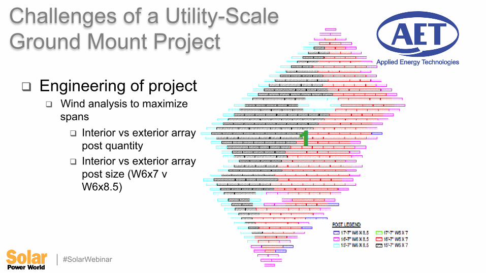
q Engineering of project q Wind analysis to maximize
spans q Interior vs exterior array
post quantity q Interior vs exterior array
post size (W6x7 v W6x8.5)
Challenges of a Utility-Scale Ground Mount Project

#SolarWebinar
q Engineering of project q Topography consideration (flood plain)
q Post length due to variations in elevation q Categorized into (3-4) post lengths
Challenges of a Utility-Scale Ground Mount Project

#SolarWebinar
q Results q (8) different array types q (7) different post P/N’s
Utility-Scale Ground Mount Project
Array#1 Array#2 Array#3 Array#4 Array#5 Array#6 Array#7 Array#8
#POST 5 5 5 6 6 6 4 4
#MDLPERROW 19 19 19 19 19 19 10 9
POSTSIZE W6x7 17'-7" W6x7 16'-7" W6x7 15'-7" W6x8.5 17'-7" W6x8.5 16'-7" W6x8.5 15'-7" W6x8.5 16'-7" W6x8.5 16'-7"
#ofArrays 14Arrays 875Arrays 894Arrays 18Arrays 314Arrays 388Arrays 1Arrays 1Arrays
#SolarWebinar
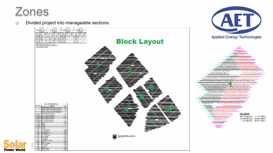
q Divided project into manageable sections
Zones
#SolarWebinar
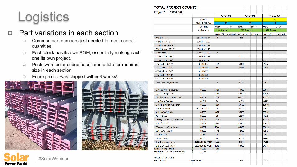
q Part variations in each section q Common part numbers just needed to meet correct
quantities. q Each block has its own BOM, essentially making each
one its own project. q Posts were color coded to accommodate for required
size in each section q Entire project was shipped within 6 weeks!
Logistics

#SolarWebinar
q Customer saved over $100k in on-site logistics q AET marshalled costs by taking a large-scale job and transforming it into (8)
smaller J.I.T. sites.
q AET delivers value-add over and above standard design and ship project
q 25+MW project built on-schedule.
Final Analysis

#SolarWebinar
Brooklyn VA Medical Center
Ø 60kW Solar Rooftop System
Ø Tall, Narrow Structure

#SolarWebinar
Design Challenges
Ø Essential Facility
Ø Water Adjacent
Ø 234’ Tall
Ø Strong Winds

#SolarWebinar
More Design Challenges
Ø Small Sized Project
Ø Code Restrictions
Ø ANachment Design
#SolarWebinar
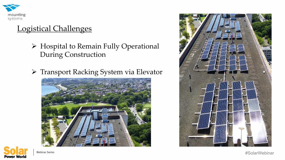
Logistical Challenges
Ø Hospital to Remain Fully Operational During Construction
Ø Transport Racking System via Elevator

#SolarWebinar
Panelized Roof Structures
#SolarWebinar
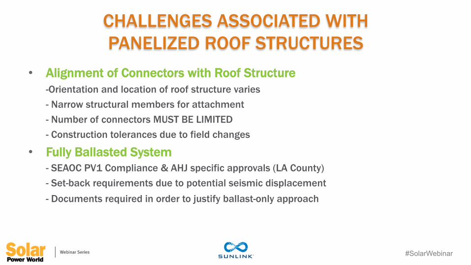
CHALLENGES ASSOCIATED WITH PANELIZED ROOF STRUCTURES
• Alignment of Connectors with Roof Structure -Orientation and location of roof structure varies - Narrow structural members for attachment - Number of connectors MUST BE LIMITED - Construction tolerances due to field changes
• Fully Ballasted System - SEAOC PV1 Compliance & AHJ specific approvals (LA County) - Set-back requirements due to potential seismic displacement - Documents required in order to justify ballast-only approach
#SolarWebinar
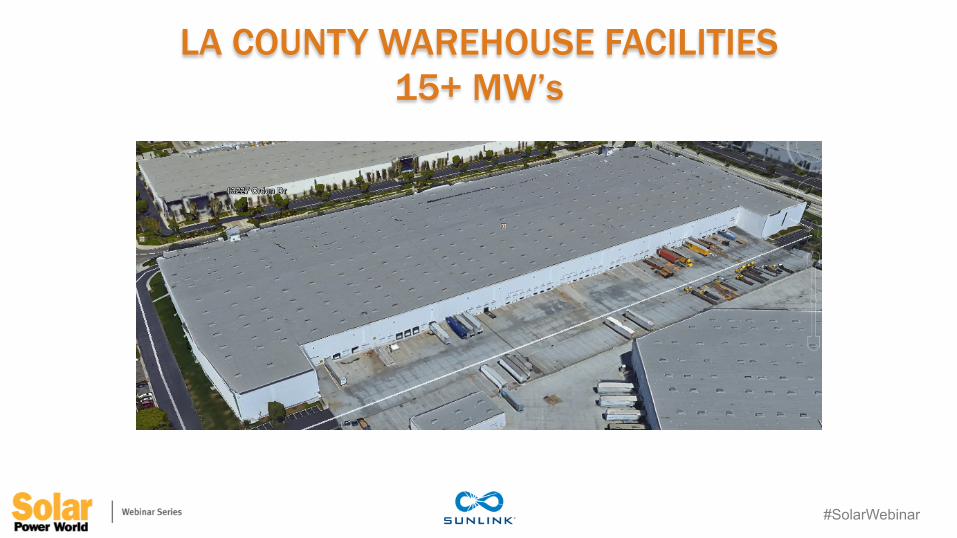
LA COUNTY WAREHOUSE FACILITIES 15+ MW’s

#SolarWebinar
#SolarWebinar
#SolarWebinar
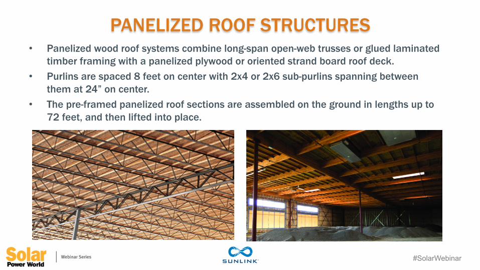
PANELIZED ROOF STRUCTURES • Panelized wood roof systems combine long-span open-web trusses or glued laminated
timber framing with a panelized plywood or oriented strand board roof deck. • Purlins are spaced 8 feet on center with 2x4 or 2x6 sub-purlins spanning between
them at 24” on center. • The pre-framed panelized roof sections are assembled on the ground in lengths up to
72 feet, and then lifted into place.

#SolarWebinar
PLYWOOD ATTACHMENT METHOD? • ICC Report does not exist for plywood connection, due to lack of embedment of
anchors, so AHJ’s and SEOR’s typically will not accept. • Connection strength so low that the number of connectors can become economically
unfeasible.

#SolarWebinar
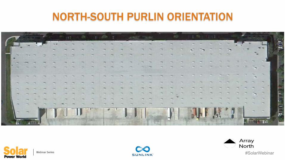
NORTH-SOUTH PURLIN ORIENTATION
#SolarWebinar
NORTH-SOUTH PURLIN ORIENTATION

#SolarWebinar
NORTH-SOUTH PURLIN ORIENTATION
8’-0” TYP

#SolarWebinar
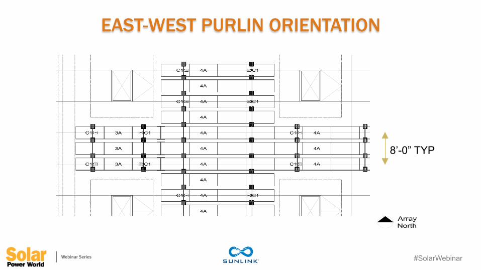
EAST-WEST PURLIN ORIENTATION
#SolarWebinar
EAST-WEST PURLIN ORIENTATION
8’-0” TYP

#SolarWebinar
CUSTOM BASE PLATE FOR ALIGNMENT
#SolarWebinar
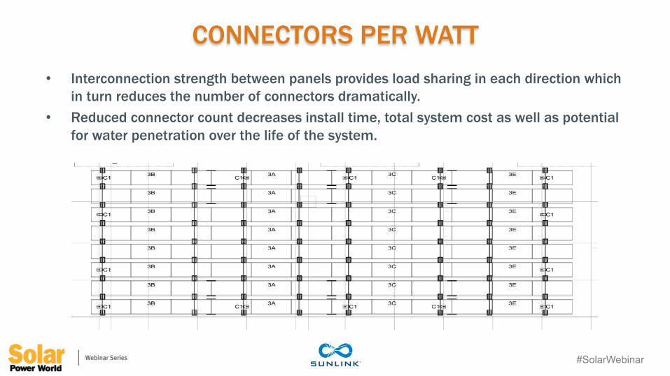
CONNECTORS PER WATT • Interconnection strength between panels provides load sharing in each direction which
in turn reduces the number of connectors dramatically. • Reduced connector count decreases install time, total system cost as well as potential
for water penetration over the life of the system.

#SolarWebinar
FULLY BALLASTED SYSTEMS ON PANELIZED ROOFS?
30
• No structural attachments to building • Ballast and self-weight provide wind and seismic resistance • No penetrations of the roofing membrane • No expensive flashing details necessary • Reduced maintenance • Overall reduced project costs
#SolarWebinar
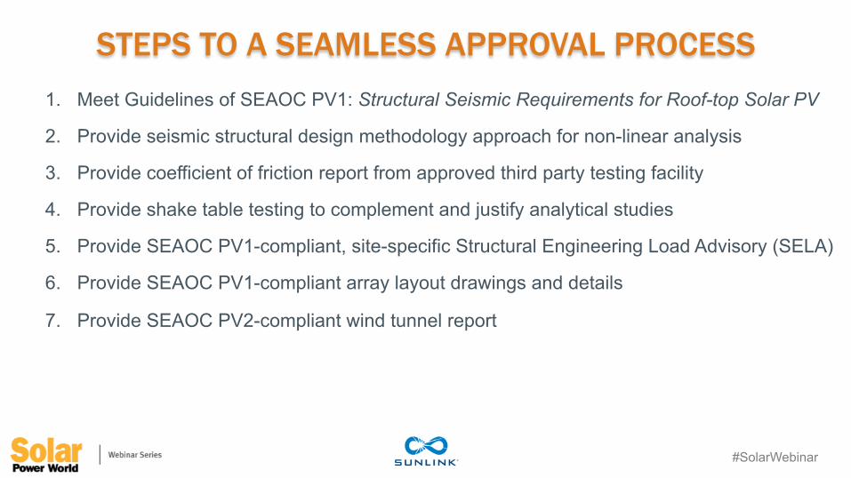
STEPS TO A SEAMLESS APPROVAL PROCESS 1. Meet Guidelines of SEAOC PV1: Structural Seismic Requirements for Roof-top Solar PV
2. Provide seismic structural design methodology approach for non-linear analysis
3. Provide coefficient of friction report from approved third party testing facility
4. Provide shake table testing to complement and justify analytical studies
5. Provide SEAOC PV1-compliant, site-specific Structural Engineering Load Advisory (SELA)
6. Provide SEAOC PV1-compliant array layout drawings and details
7. Provide SEAOC PV2-compliant wind tunnel report

#SolarWebinar
FULLY BALLASTED SYSTEMS – SEAOC PV1 • Unattached (ballast-only) systems are not attached to the roof
structure. o Resistance to wind and seismic forces is provided by weight and
friction. • Unattached (ballast-only) systems are permitted when all of the
following conditions are met: o The maximum roof slope at the location of the array is less than or
equal to 7 degrees (12.3 percent). o The height above the roof suface to the center of mass of the solar
array is less than the smaller of 36 inches and half the least plan dimension of the supporting base of the array.
o The system is designed to accommodate the seismic displacement determined by one of the following procedures:
• Prescriptive design seismic displacement • Nonlinear response history analysis • Shake table testing
#SolarWebinar
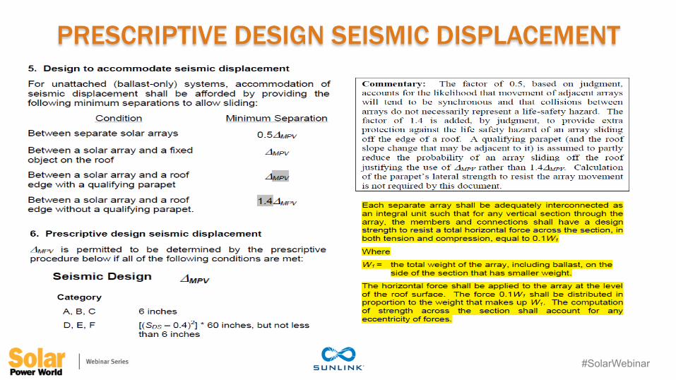
PRESCRIPTIVE DESIGN SEISMIC DISPLACEMENT

#SolarWebinar
FRICTION REPORT
#SolarWebinar
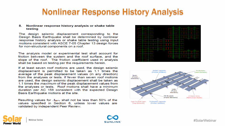
Nonlinear Response History Analysis

#SolarWebinar
Nonlinear Response History Analysis
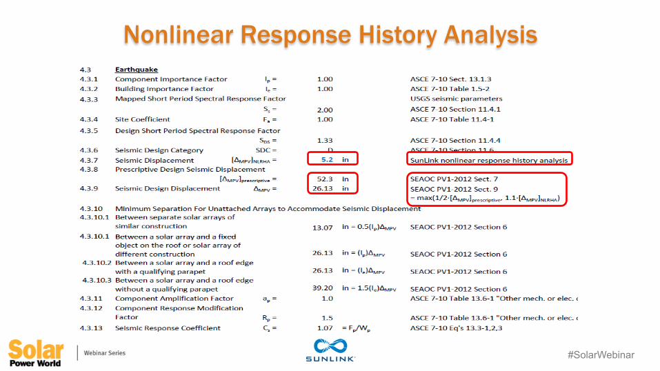
#SolarWebinar
Nonlinear Response History Analysis

#SolarWebinar
SHAKE TABLE TESTING • Objectives of Tests
o Validate and calibrate the nonlinear computer analysis models
o Produce seismic qualification test reports and documentation
o Provide information to support the creation of new structural engineering standards
• Shake Table Facility o 20 ft x 20 ft table size o Still the largest 6 DOF shake table in the US o Can test structures, weighing 100,000 lbs, to
horizontal accelerations of 1.5 g o +/- 5 in. horizontal displacement capacity o +/- 2 in. vertical displacement capacity o +/- 40 in./sec velocity capacity
#SolarWebinar
Aaron Faust VP Business Development
Applied Energy Technologies (AET)
[email protected] @AETenergy
John Klinkman VP Engineering Applied Energy
Technologies (AET) [email protected]
@AETenergy
Brooke Stubben, P.E. Manager of Applications
Engineering Mounting Systems, Inc
Overcoming the toughest solar mounting problems
Jason Luhn Project Director
SunLink [email protected]
@sunlink
Questions?