overview of interstate hydrogen pipeline systems of interstate hydrogen pipeline systems...
TRANSCRIPT
Overview of Interstate Hydrogen Pipeline Systems
ANL/EVS/TM/08-2
Environmental Science Division
Availability of This ReportThis report is available, at no cost, at http://www.osti.gov/bridge. It is also available on paper to the U.S. Department of Energy and its contractors, for a processing fee, from:
U.S. Department of Energy
OfficeofScientificandTechnicalInformation
P.O. Box 62
Oak Ridge, TN 37831-0062
phone (865) 576-8401
fax (865) 576-5728
Disclaimer
This report was prepared as an account of work sponsored by an agency of the United States Government. Neither the United States
Governmentnoranyagencythereof,norUChicagoArgonne,LLC,noranyoftheiremployeesorofficers,makesanywarranty,express
or implied, or assumes any legal liability or responsibility for the accuracy, completeness, or usefulness of any information, apparatus,
product,orprocessdisclosed,orrepresentsthatitsusewouldnotinfringeprivatelyownedrights.Referencehereintoanyspecific
commercial product, process, or service by trade name, trademark, manufacturer, or otherwise, does not necessarily constitute or imply
its endorsement, recommendation, or favoring by the United States Government or any agency thereof. The views and opinions of
documentauthorsexpressedhereindonotnecessarilystateorreflectthoseoftheUnitedStatesGovernmentoranyagencythereof,
Argonne National Laboratory, or UChicago Argonne, LLC.
About Argonne National Laboratory Argonne is a U.S. Department of Energy laboratory managed by UChicago Argonne, LLC under contract DE-AC02-06CH11357. The Laboratory’s main facility is outside Chicago, at 9700 South Cass Avenue, Argonne, Illinois 60439. For information about Argonne, see www.anl.gov.


iii
CONTENTS
NOTATION.............................................................................................................................. vii 1 INTRODUCTION .............................................................................................................. 1 2 COMMON FACILITY CHARACTERISTICS ................................................................. 3
2.1 Transmission Pipelines .............................................................................................. 3 2.2 Compressor Stations .................................................................................................. 4 2.3 Metering Stations ....................................................................................................... 5 2.4 City Gate Stations ...................................................................................................... 6 2.5 Valves ........................................................................................................................ 6 2.6 Pig Launching/Receiving Facilities ........................................................................... 6 2.7 SCADA Centers......................................................................................................... 6 2.8 Telecommunications Towers ..................................................................................... 6 2.9 Access Roads ............................................................................................................. 7
3 EXISTING STANDARDS AND REGULATIONS .......................................................... 9 4 CONSTRUCTION, OPERATION, AND MAINTENANCE............................................ 11
4.1 Hydrogen Pipeline Construction................................................................................ 11 4.1.1 General Pipeline Construction Procedures .................................................... 11
4.1.1.1 Permits ............................................................................................ 12 4.1.1.2 Survey and Staking ......................................................................... 13 4.1.1.3 Clearing and Grading...................................................................... 13 4.1.1.4 Trenching ........................................................................................ 13 4.1.1.5 Pipe Stringing, Bending, and Welding ........................................... 14 4.1.1.6 Lowering-in and Backfilling........................................................... 16 4.1.1.7 Hydrostatic Testing......................................................................... 17 4.1.1.8 Final Tie-in...................................................................................... 18 4.1.1.9 Commissioning ............................................................................... 18 4.1.1.10 Cleanup and Restoration ................................................................. 18
4.1.2 Special Construction Procedures ................................................................... 21 4.1.2.1 Road, Highway, and Railroad Crossings ........................................ 21 4.1.2.2 Steep Terrain................................................................................... 22 4.1.2.3 Waterbody Crossings ...................................................................... 23 4.1.2.4 Wetland Crossings .......................................................................... 26 4.1.2.5 Blasting ........................................................................................... 30 4.1.2.6 Fences and Grazing......................................................................... 30 4.1.2.7 Rugged Topography........................................................................ 30 4.1.2.8 Construction Immediately Adjacent to Other Pipelines ................. 31
iv
CONTENTS (Cont.)
4.1.3 Aboveground Facility Construction Procedures ............................................ 33 4.1.3.1 Compressor Stations ....................................................................... 33 4.1.3.2 Meter Stations, Valves, and Pig Launcher/Receiver Facilities....... 34 4.1.3.3 Telecommunications Towers .......................................................... 35 4.1.3.4 Corrosion Protection and Detection Systems ................................. 35
4.2 Operation and Maintenance ....................................................................................... 36 4.3 Monitoring and Maintenance..................................................................................... 36
4.3.1 Pipeline Integrity............................................................................................ 37 4.3.2 Future Plans and Abandonment ..................................................................... 37
4.4 Reliability and Congestion Issues.............................................................................. 37 4.5 Transmission Enhancement Technology ................................................................... 38
5 REFERENCES ................................................................................................................... 39
FIGURES
4.1-1 Bulldozer Grading Pipeline ROW ............................................................................. 13
4.1-2 Pipeline Trenching Operations .................................................................................. 14
4.1-3 Pipe Bending Machine............................................................................................... 15
4.1-4 Pipeline Welding........................................................................................................ 15
4.1-5 Crew Coating a Pipeline Field Joint .......................................................................... 16
4.1-6 Crew Lowering a Pipeline into a Trench ................................................................... 17
4.1-7 Trench Backfilling Operations................................................................................... 17
4.1-8 Typical Open-Cut Waterbody Crossing Method ....................................................... 24
4.1-9 Typical Dam-and-Pump Waterbody Crossing Method ............................................. 25
4.1-10 Horizontal Directional Drilling Operation................................................................. 26
4.1-11 Typical HDD Waterbody Crossing Method .............................................................. 27
4.1-12 Typical Pipeline ROW in Wetlands........................................................................... 28
v
FIGURES (Cont.)
4.1-13 Pipeline for Wetland Installation Encased in Concrete to Counteract Positive Buoyancy ................................................................................................................... 29
4.1-14 Typical Two-Tone Construction ROW ..................................................................... 31
4.1-15 Typical Construction ROW When Adjacent to Existing Pipeline............................. 32
TABLES
4.1-1 Breakdown of Pipeline Construction Workforce....................................................... 19
4.1-2 Typical Emissions from the Construction of a Pipeline Segment ............................. 20
4.1-3 Typical Emissions from the Construction of a Natural Gas Compressor Station ........................................................................................................................ 34
4.2-1 Typical Pollutant Emissions from Hydrogen Compressor Station Operations ......... 36

vi
vii
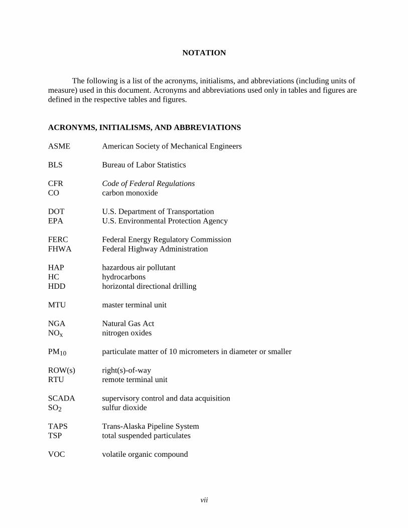
NOTATION
The following is a list of the acronyms, initialisms, and abbreviations (including units of measure) used in this document. Acronyms and abbreviations used only in tables and figures are defined in the respective tables and figures. ACRONYMS, INITIALISMS, AND ABBREVIATIONS ASME American Society of Mechanical Engineers BLS Bureau of Labor Statistics CFR Code of Federal Regulations CO carbon monoxide DOT U.S. Department of Transportation EPA U.S. Environmental Protection Agency FERC Federal Energy Regulatory Commission FHWA Federal Highway Administration HAP hazardous air pollutant HC hydrocarbons HDD horizontal directional drilling MTU master terminal unit NGA Natural Gas Act NOx nitrogen oxides PM10 particulate matter of 10 micrometers in diameter or smaller ROW(s) right(s)-of-way RTU remote terminal unit SCADA supervisory control and data acquisition SO2 sulfur dioxide TAPS Trans-Alaska Pipeline System TSP total suspended particulates VOC volatile organic compound
viii
UNITS OF MEASURE °C degree(s) Centigrade gal gallon(s) ksi thousands of pounds per square inch
lb pound(s) psia pound(s) per square inch absolute psig pound(s) per square inch gauge tpy ton(s) per year
1
1 INTRODUCTION The use of hydrogen in the energy sector of the United States is projected to increase significantly in the future. Current uses are predominantly in the petroleum refining sector, with hydrogen also being used in the manufacture of chemicals and other specialized products. Growth in hydrogen consumption is likely to appear in the refining sector, where greater quantities of hydrogen will be required as the quality of the raw crude decreases, and in the mining and processing of tar sands and other energy resources that are not currently used at a significant level. Furthermore, the use of hydrogen as a transportation fuel has been proposed both by automobile manufacturers and the federal government. Assuming that the use of hydrogen will significantly increase in the future, there would be a corresponding need to transport this material. A variety of production technologies are available for making hydrogen, and there are equally varied raw materials. Potential raw materials include natural gas, coal, nuclear fuel, and renewables such as solar, wind, or wave energy. As these raw materials are not uniformly distributed throughout the United States, it would be necessary to transport either the raw materials or the hydrogen long distances to the appropriate markets. While hydrogen may be transported in a number of possible forms, pipelines currently appear to be the most economical means of moving it in large quantities over great distances. One means of controlling hydrogen pipeline costs is to use common rights-of-way (ROWs) whenever feasible. For that reason, information on hydrogen pipelines is the focus of this document. Many of the features of hydrogen pipelines are similar to those of natural gas pipelines. Furthermore, as hydrogen pipeline networks expand, many of the same construction and operating features of natural gas networks would be replicated. As a result, the description of hydrogen pipelines will be very similar to that of natural gas pipelines. The following discussion will focus on the similarities and differences between the two pipeline networks. Hydrogen production is currently concentrated in refining centers along the Gulf Coast and in the Farm Belt. These locations have ready access to natural gas, which is used in the steam methane reduction process to make bulk hydrogen in this country. Production centers could possibly change to lie along coastlines, rivers, lakes, or rail lines, should nuclear power or coal become a significant energy source for hydrogen production processes. Should electrolysis become a dominant process for hydrogen production, water availability would be an additional factor in the location of production facilities. Once produced, hydrogen must be transported to markets. A key obstacle to making hydrogen fuel widely available is the scale of expansion needed to serve additional markets. Developing a hydrogen transmission and distribution infrastructure would be one of the challenges to be faced if the United States is to move toward a hydrogen economy. Initial uses of hydrogen are likely to involve a variety of transmission and distribution methods. Smaller users would probably use truck transport, with the hydrogen being in either the liquid or gaseous form. Larger users, however, would likely consider using pipelines. This option would require specially constructed pipelines and the associated infrastructure.
2
Pipeline transmission of hydrogen dates back to late 1930s. These pipelines have generally operated at less than 1,000 pounds per square inch (psi), with a good safety record. Estimates of the existing hydrogen transmission system in the United States range from about 450 to 800 miles. Estimates for Europe range from about 700 to 1,100 miles (Mohipour et al. 2004; Amos 1998). These seemingly large ranges result from using differing criteria in determining pipeline distances. For example, some analysts consider only pipelines above a certain diameter as transmission lines. Others count only those pipelines that transport hydrogen from a producer to a customer (e.g., those pipelines designed for in-plant transport of hydrogen for use as feedstock or fuel are not counted). Operational status and hydrogen purity levels are also factors in defining these ranges. Hydrogen pipelines in the United States are predominantly along the Gulf Coast and connect major hydrogen producers with well-established, long-term customers. These hydrogen transmission systems pall by comparison with the 180,000-mile natural gas transmission pipeline. Since 1939, Germany has had a 130-mile pipeline carrying 20,000 lb/hour of hydrogen in a 10-inch pipe at 290 psi gauge (psig). The longest hydrogen pipeline in Europe is owned by Air Liquide and extends 250 miles from Northern France to Belgium. In theory, a blend of up to 20% hydrogen in natural gas can be transported without modifying natural gas pipelines (Oney et al. 1994). Modifying the same pipelines to carry pure hydrogen, however, requires addressing a number of issues, including the potential for embrittlement of some steels and sealing difficulties at fittings that are tight enough to prevent natural gas from escaping, but possibly not hydrogen. Regardless of these materials issues, construction of new pipelines to carry hydrogen could benefit from joint use of existing ROWs for natural gas distribution.
3
2 COMMON FACILITY CHARACTERISTICS
Hydrogen pipeline systems are fundamentally the same as natural gas systems, in that they involve similar components such as transmission pipelines, compressor stations, and city gates. 2.1 TRANSMISSION PIPELINES Design requirements for hydrogen pipelines are still evolving. Although there are several hundred miles of hydrogen pipelines throughout the world, most hydrogen pipelines are designed to transport hydrogen only short distances, from the production facility to the end user. Many such applications typically represent only a few hundred feet of pipeline and operate with maximum pressures of considerably less than the 1,000 psi absolute (psia) or more that would likely be required for long-distance pipeline transmission of hydrogen. The safety record for these pipelines is considered to be very good. This safe history notwithstanding, the definition of required safety margins, codes, and standards for application to large-scale hydrogen transport remains a work in progress. It is therefore not possible at this time to definitively specify the design details of hydrogen transmission pipelines. However, based on the design parameters of some hydrogen pipelines and on experience with natural gas pipelines, it is reasonable to suggest some design parameters that could very well be applicable to the flow rates, distances, and pressures associated with long-distance transmission of hydrogen via pipeline. At a given pressure, the energy density of hydrogen is approximately one-third that of natural gas. However, for the same pipe diameter and pressure, hydrogen flows approximately three times as fast as natural gas. As a result, if hydrogen compressors could be operated to meet similar pressure requirements as natural gas compressors, it could be expected that hydrogen pipe diameters would approach those for natural gas transmission pipelines. As noted in the discussion of natural gas pipelines, pipe diameters of up to 48 inches are seen. Actual hydrogen pipeline diameters would of course depend on hydrogen demand, the pressures achievable, and codes and standards that are yet to be developed. One school of thought suggests that existing natural gas pipelines could be converted to hydrogen use. However, in addition to the issue of compressor power noted above, there are questions as to whether fittings, gaskets, and other materials designed for natural gas pipelines could withstand hydrogen diffusion. Conversion from natural gas to hydrogen will not be described further in this document, as the issues to be addressed in doing so are the same as those for natural gas and hydrogen pipelines separately. Historically, carbon steel or stainless steel has been used to transport hydrogen. Gray, ductile, or cast iron and nickel steels have been used but are not considered suitable for high-pressure hydrogen transmission (Mohipour et al. 2004). Austenitic stainless steels, aluminum (including alloys), copper (including alloys), and titanium (including alloys) are generally applicable for most hydrogen service applications. High-strength steels (above 100 ksi) are more susceptible to hydrogen embrittlement, so the use of thicker, low-strength steels is sometimes
4
recommended for hydrogen pipelines. Polymer/fiberglass-reinforced pipes have been used in specific applications such as for in-plant piping at moderate temperatures. As is the case with natural gas pipelines, welding is the preferred joint technology for hydrogen pipelines. One of the questions to be resolved before hydrogen pipelines can be economically built is that of potential hydrogen embrittlement, which tends to occur with higher strength steels. Additional questions such as loss of material strength, fracture toughness, enhanced fatigue crack growth rates, low cycle fatigue, subcritical and sustained load cracking, susceptibility to stress corrosion cracking, and hydrogen-induced cracking in welds and joints must also be answered before there can be a large-scale application of hydrogen pipelines. Although design requirements for hydrogen pipelines have yet to be established, some reasonable assumptions can be made. These assumptions are based on operating experience with both natural gas and hydrogen and on the expectations for large-scale hydrogen delivery. For example, it can be reasonably assumed that hydrogen pipelines will be constructed of carbon or stainless steel Schedule 40 welded pipe. Consistent with Department of Transportation (DOT) requirements and conventional practice, the top of the pipe will be at least 30 inches below ground, and the pipe will sit on a 4- to 12-inch crushed rock or soft clay base. Again consistent with conventional practice, it can be assumed that the pipe would be precoated on its exterior with a fusion-bond epoxy or a polyethylene sleeve to inhibit corrosion. As with natural gas pipelines, it is likely that standards promulgated by the American Petroleum Institute would be used in the construction and operation of hydrogen pipelines. 2.2 COMPRESSOR STATIONS As noted above, the volumetric energy density of hydrogen gas is only about one-third that of natural gas at the same pressure. Because compressors operate on the basis of volume rather than energy content, considerably higher compression horsepower would be required to move comparable amounts of energy as compared to the power requirements for a natural gas system. Hydrogen is difficult to compress, as it consists of very small molecules, so positive-displacement compressors are typically used. Hydrogen compressors are expensive due to the required materials, the physical size needed to supply the needed compression power, and the redundancy needed to provide reliability. Hydrogen compressors must have tight tolerances and/or special seals to reach the pressures required for high-volume transmission. At elevated pressure and temperature, hydrogen can permeate carbon steel, resulting in decarburization. Conventional mild steel has been used as pipeline material in Germany and France since 1938, and alloy steels with chromium and molybdenum have been suggested as compressor materials. Multistage reciprocating machines to produce pressures of 700 to 1,000 psig are considered state-of-the-art, and additional research and development activities are under way in both the private and public sectors. These units have high maintenance costs due to wearing components such as valves, rider bands, and piston rings (Drnevich 2003). These compressors are typically nonlubricated (oil-free) so as to reduce the potential for oil contamination of the hydrogen (Mintz et al. 2002).
5
Current reciprocating compressors are costly, are subject to excessive wear, have poor reliability, and often use lubricants that can contaminate the hydrogen. Research is currently under way to minimize moving parts and to address wear through new designs (centrifugal, linear, guided rotor, and electrochemical) and improved compressor materials. In selecting equipment for pipelines, it should be noted that centrifugal compressors create more operating problems than reciprocating compressors. Considering the relative lightness of hydrogen, its recompression ratio is four times lower than for natural gas for a given rotor speed (Bossel 2003). This necessitates a greater number of stages. Because of its low specific gravity, hydrogen tends to return to the compressor inlet of centrifugal compressors, thereby limiting their efficiency. Three to five stages of compression are required to deliver hydrogen at pipeline pressures because water-cooled positive-displacement compressors can achieve a pressure ratio of only about 3 per stage. Hydrogen compressors have both high capital investment costs and high operating costs. It is generally assumed that this equipment would have to be subjected to a significant (i.e., costly) overhaul every few years (typically assumed to be at 5-year intervals in Department of Energy [DOE] programs). Hydrogen compressors are the subject of several research and development programs (both within DOE and in the private sector), with the expectation that more definitive information on their cost and performance characteristics can be developed. Compressor stations are powered by compressors that are each rated at several thousand horsepower. Most compressor stations are fully automated. The compressors are typically housed in a metal building with pipe appurtenances and other critical elements above ground. If the hydrogen pipeline shared a common corridor with a natural gas pipeline or a electricity transmission line, it would be comparatively easy to bleed some natural gas or electricity to energize the hydrogen compressor. Alternatively, a quantity of hydrogen could be fed to the compressor for the same purpose. Which option is used in any specific case would be determined by the availability of various energy sources and the relative economic value of each. The spacing between hydrogen compressors along a pipeline would be determined by operational and economic factors. It is likely that the spacing between hydrogen compressors would be equal to or greater than the 40 to 100 miles common for natural gas transmission pipelines. 2.3 METERING STATIONS Although details of hydrogen transmission pipelines have yet to be developed, it is likely that metering stations would be placed along the pipelines. In a manner similar to that for natural gas pipelines, these metering stations would allow pipeline companies to monitor and manage the hydrogen in their pipes. Essentially, these metering stations measure the flow rate and pressure of the hydrogen along the pipeline, thus allowing pipeline companies to track it as it flows along the pipeline.
6
2.4 CITY GATE STATIONS The potential uses for large quantities of hydrogen are as a feedstock or fuel for industrial facilities or as a transportation fuel. In either case, it is likely that hydrogen pressure would have to be reduced from transmission pipeline levels to distribution system levels. In a manner similar to that for natural gas systems, pressure regulators would likely be used to control the hydrogen flow rate through the station and to maintain the desired pressure in the distribution system. Should it be decided to add any additives to the hydrogen as it enters a distribution system, such as the odorant added to natural gas, it is likely that this would be done at the city gate stations. 2.5 VALVES Interstate pipelines include a great number of valves along their entire length. These valves work like gateways; they are usually open and allow hydrogen to flow freely, but they could be used to stop the flow along a certain section of pipe. Due to the small molecular size of hydrogen, considerable research and development has been directed toward the development of effective valves. This component of a hydrogen pipeline network is likely to be considerably more expensive than the corresponding valves in natural gas pipelines due to tighter tolerances and possibly more costly materials of construction. 2.6 PIG LAUNCHING/RECEIVING FACILITIES As with natural gas pipelines, hydrogen pipelines are likely to have pig launching and receiving equipment to allow the pipeline to accommodate a high-resolution internal inspection tool. Pigs are devices that are placed inside a pipe to clean the inside of the pipeline and/or to monitor its condition. Launchers and receivers are facilities that enable pigs to be inserted into or removed from the pipeline. 2.7 SCADA CENTERS Hydrogen pipeline networks can be expected to have supervisory control and data acquisition (SCADA) systems that are similar to those for natural gas pipeline networks. The basic objective of such a system is to monitor conditions (e.g., flow rate, pressure, temperature, and valve positions) throughout the pipeline network and make any necessary changes in these conditions. 2.8 TELECOMMUNICATIONS TOWERS In all SCADA systems, the master terminal unit (MTU) and remote terminal units (RTUs) communicate through a defined network of some type, requiring telecommunications towers. Hydrogen pipeline network SCADA systems would have similar requirements.

7
2.9 ACCESS ROADS Hydrogen pipelines would require access roads for construction, operations, and maintenance activities. These roads would be constructed and maintained in exactly the same manner as for natural gas pipelines. If the hydrogen pipeline shares a ROW with a natural gas pipeline and/or an electricity transmission line, the access roads would be shared.

8
9
3 EXISTING STANDARDS AND REGULATIONS A number of federal and state agencies have standards and regulations that affect natural gas pipelines and are likely to also impact hydrogen pipelines. These agencies include the following:
• Department of Transportation;
• Federal Energy Regulatory Commission;
• Office of Pipeline Safety;
• National Transportation Safety Board;
• U.S. Coast Guard;
• Federal Emergency Management Agency;
• Public Utility Commission; and • State and local fire departments.
Hydrogen pipeline construction standards are currently under development. The American Society of Mechanical Engineers (ASME) Board on Pressure Technology Codes and Standards has initiated the development of an independent consensus standard or code for hydrogen pipelines. Although it is anticipated that many of the codes and standards will be similar to those for natural gas pipelines, differences in physical properties will necessitate some differences. The following are some of the differences (Kreith and West 2004):
• Detonation required to ignite hydrogen is a fraction of that required for natural gas or gasoline, and the resultant explosive force is lower.
• A hydrogen flame burns quickly and releases only about 10% of the heat that
hydrocarbons release. This means that a hydrogen explosion and fire would do less damage to the immediate surroundings than a natural gas or gasoline fire, while also creating less damaging gases caused by the burning of secondary material.
• It is difficult to detonate hydrogen in the open air, thus making it a safer fuel
than some others. It is 14.4 times lighter than air and rises at a speed of 66 feet per second.
• Burning hydrogen releases negligible emissions at the point of use, with the
exception of nitrogen oxides (NOx), which are greater because of the high temperature of hydrogen combustion.

10
• Hydrogen is a colorless and odorless gas with a density of 0.09 g/L (air is 14.4 times more dense). It boils at –252.87°C.
• 1 lb of hydrogen contains the same amount of energy as 2.1 lb of natural gas
or 2.8 lb of gasoline. Hydrogen burns in air at concentrations in the range of 4 to 75% by volume. The ignition energy for a stoichiometric fuel/air mixture is less than 10% of that for methane.
11
4 CONSTRUCTION, OPERATION, AND MAINTENANCE 4.1 HYDROGEN PIPELINE CONSTRUCTION It is likely that welding procedures and leak testing would be more exacting for hydrogen pipelines than for natural gas pipelines. These likely requirements stem from the small molecular size of hydrogen as compared to natural gas. Other construction practices are likely to be very similar to those for natural gas pipelines. At a minimum, any proposed hydrogen gas facility would be designed, constructed, tested, and operated in accordance with all applicable requirements included in the U.S. Department of Transportation (DOT) regulations in Title 49, Part 192, of the Code of Federal Regulations (49 CFR Part 192), “Transportation of Natural Gas and Other Gas by Pipeline: Minimum Federal Safety Standards,” and other applicable federal and state regulations. These regulations are intended to ensure adequate protection for the public and to prevent natural gas pipeline accidents and failures. Among other design standards, Part 192 specifies pipeline material and qualification, minimum design requirements, and protection from internal, external, and atmospheric corrosion. 4.1.1 General Pipeline Construction Procedures Before starting construction, engineering surveys would be conducted of the ROW centerline, and extra workspaces and complete land or easement acquisition on private and state land would be finalized. If the necessary land rights or easements could not be obtained through good faith negotiations with landowners and the project were approved by the Federal Energy Regulatory Commission (FERC), the pipeline company could use the right of eminent domain granted to it under Section 7(h) of the Natural Gas Act (NGA) to obtain an easement. The pipeline company would still be required to compensate the landowners for the ROW, as well as for any damages incurred during construction. The pipeline company would generally pay market price for the property. However, the level of compensation would be determined by the court system according to state laws regarding eminent domain. Eminent domain would be used only as a last resort, because the process could take up to 2 to 3 years (FERC 2007). The landowner normally is compensated a fair market value for a permanent easement, which typically allows the landowner continued use and enjoyment of the aboveground property, but with some limitations. The limitations typically prohibit excavation as well as structures and trees within the easement, in order to preserve safe access of maintenance equipment when necessary and to allow for uninhibited aerial inspection of the pipeline system. The landowner is generally compensated a lower value for the use of a temporary construction easement, since this land reverts back to the landowner after construction for full use and enjoyment without any restrictions, although ROW cleanup could continue for several years.
12
Additionally, landowners are compensated for any damages or losses, such as loss of crop revenues, they may incur as a result of construction across their property normally through several growing seasons. Overland pipeline construction in a rural environment would generally proceed as a moving assembly line as summarized below. Typically, job-specific work crews would construct the facilities associated with compressor stations. Standard pipeline construction is composed of specific activities including survey and staking of the ROW, clearing and grading, trenching, pipe stringing, bending, welding, lowering-in, backfilling, hydrostatic testing, tie-in, cleanup, and commissioning. In addition to standard pipeline construction methods, the pipeline company would use special construction techniques where warranted by site-specific conditions. These special techniques would be used when constructing across rugged terrain, waterbodies, wetlands, paved roads, highways, and railroads.
4.1.1.1 Permits Prior to construction, a proposed pipeline project must obtain numerous local, state, and federal permits and clearances. The permits address all natural resources — land, air, water, vegetation, and wildlife — as well as the interests of the general public. Requirements generally include:
• Local
− Building permits − Road crossing permits
• State
− Land (Erosion and Sedimentation Permit) − Water (Hydrostatic Testwater Acquisition and Discharge Permit,
Stormwater Discharge Permit) − Stream and river crossings (State Environmental Agency) − Cultural resources preservation (State Historic Preservation Office) − Threatened and endangered species preservation (State Fish and Wildlife
Agency) − Air emissions (State Environmental Agency)
• Federal
− Wetlands preservation and crossings (U.S. Army Corps of Engineers) − Streams and rivers (U.S. Army Corps of Engineers) − Threatened and endangered species (U.S. Fish and Wildlife Service) − Air emissions (U.S. Environmental Protection Agency)
13
− Environmental resource reports − Noise (FERC) − Highway permits (Federal Highway Administration [FHWA]) as well as
private company owner permits (such as for railroads) Copies of all permits and permit applications are submitted to FERC prior to beginning construction, if required.
4.1.1.2 Survey and Staking The first step of construction involves marking the limits of the approved work area (i.e., construction ROW boundaries, additional temporary workspace areas) and flagging the locations of approved access roads and foreign utility lines. Wetland boundaries and other environmentally sensitive areas also would be marked or fenced for protection at this time. Before the pipeline trench would be excavated, a survey crew would stake the centerline of the proposed trench.
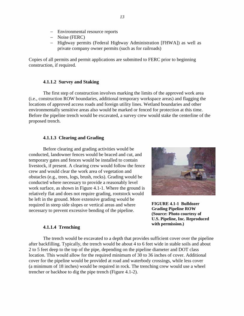
4.1.1.3 Clearing and Grading Before clearing and grading activities would be conducted, landowner fences would be braced and cut, and temporary gates and fences would be installed to contain livestock, if present. A clearing crew would follow the fence crew and would clear the work area of vegetation and obstacles (e.g., trees, logs, brush, rocks). Grading would be conducted where necessary to provide a reasonably level work surface, as shown in Figure 4.1-1. Where the ground is relatively flat and does not require grading, rootstock would be left in the ground. More extensive grading would be required in steep side slopes or vertical areas and where necessary to prevent excessive bending of the pipeline.
4.1.1.4 Trenching The trench would be excavated to a depth that provides sufficient cover over the pipeline after backfilling. Typically, the trench would be about 4 to 6 feet wide in stable soils and about 2 to 5 feet deep to the top of the pipe, depending on the pipeline diameter and DOT class location. This would allow for the required minimum of 30 to 36 inches of cover. Additional cover for the pipeline would be provided at road and waterbody crossings, while less cover (a minimum of 18 inches) would be required in rock. The trenching crew would use a wheel trencher or backhoe to dig the pipe trench (Figure 4.1-2).
FIGURE 4.1-1 Bulldozer Grading Pipeline ROW (Source: Photo courtesy of U.S. Pipeline, Inc. Reproduced with permission.)
14
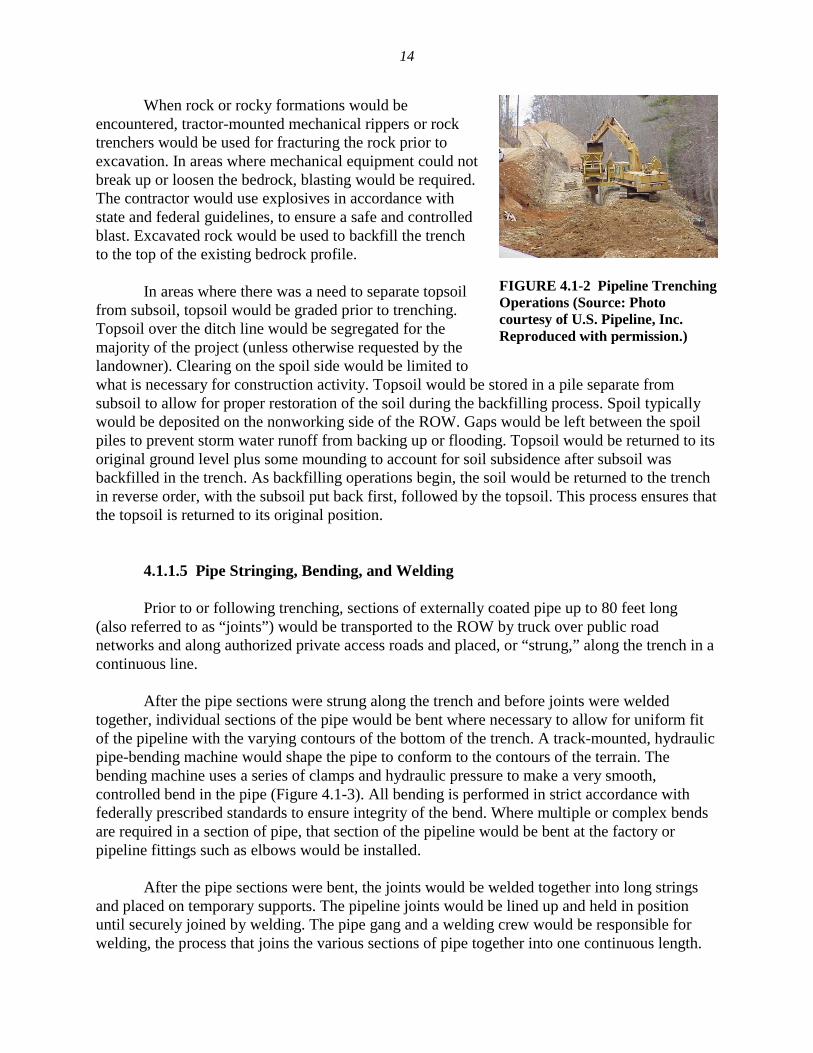
When rock or rocky formations would be encountered, tractor-mounted mechanical rippers or rock trenchers would be used for fracturing the rock prior to excavation. In areas where mechanical equipment could not break up or loosen the bedrock, blasting would be required. The contractor would use explosives in accordance with state and federal guidelines, to ensure a safe and controlled blast. Excavated rock would be used to backfill the trench to the top of the existing bedrock profile. In areas where there was a need to separate topsoil from subsoil, topsoil would be graded prior to trenching. Topsoil over the ditch line would be segregated for the majority of the project (unless otherwise requested by the landowner). Clearing on the spoil side would be limited to what is necessary for construction activity. Topsoil would be stored in a pile separate from subsoil to allow for proper restoration of the soil during the backfilling process. Spoil typically would be deposited on the nonworking side of the ROW. Gaps would be left between the spoil piles to prevent storm water runoff from backing up or flooding. Topsoil would be returned to its original ground level plus some mounding to account for soil subsidence after subsoil was backfilled in the trench. As backfilling operations begin, the soil would be returned to the trench in reverse order, with the subsoil put back first, followed by the topsoil. This process ensures that the topsoil is returned to its original position.
4.1.1.5 Pipe Stringing, Bending, and Welding Prior to or following trenching, sections of externally coated pipe up to 80 feet long (also referred to as “joints”) would be transported to the ROW by truck over public road networks and along authorized private access roads and placed, or “strung,” along the trench in a continuous line. After the pipe sections were strung along the trench and before joints were welded together, individual sections of the pipe would be bent where necessary to allow for uniform fit of the pipeline with the varying contours of the bottom of the trench. A track-mounted, hydraulic pipe-bending machine would shape the pipe to conform to the contours of the terrain. The bending machine uses a series of clamps and hydraulic pressure to make a very smooth, controlled bend in the pipe (Figure 4.1-3). All bending is performed in strict accordance with federally prescribed standards to ensure integrity of the bend. Where multiple or complex bends are required in a section of pipe, that section of the pipeline would be bent at the factory or pipeline fittings such as elbows would be installed. After the pipe sections were bent, the joints would be welded together into long strings and placed on temporary supports. The pipeline joints would be lined up and held in position until securely joined by welding. The pipe gang and a welding crew would be responsible for welding, the process that joins the various sections of pipe together into one continuous length.
FIGURE 4.1-2 Pipeline Trenching Operations (Source: Photo courtesy of U.S. Pipeline, Inc. Reproduced with permission.)
15
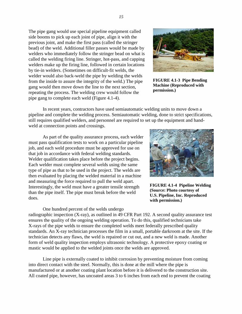
The pipe gang would use special pipeline equipment called side booms to pick up each joint of pipe, align it with the previous joint, and make the first pass (called the stringer bead) of the weld. Additional filler passes would be made by welders who immediately follow the stringer bead on what is called the welding firing line. Stringer, hot-pass, and capping welders make up the firing line, followed in certain locations by tie-in welders. (Sometimes on difficult-fit welds, the welder would also back-weld the pipe by welding the welds from the inside to assure the integrity of the weld.) The pipe gang would then move down the line to the next section, repeating the process. The welding crew would follow the pipe gang to complete each weld (Figure 4.1-4). In recent years, contractors have used semiautomatic welding units to move down a pipeline and complete the welding process. Semiautomatic welding, done to strict specifications, still requires qualified welders, and personnel are required to set up the equipment and hand-weld at connection points and crossings. As part of the quality assurance process, each welder must pass qualification tests to work on a particular pipeline job, and each weld procedure must be approved for use on that job in accordance with federal welding standards. Welder qualification takes place before the project begins. Each welder must complete several welds using the same type of pipe as that to be used in the project. The welds are then evaluated by placing the welded material in a machine and measuring the force required to pull the weld apart. Interestingly, the weld must have a greater tensile strength than the pipe itself. The pipe must break before the weld does. One hundred percent of the welds undergo radiographic inspection (X-ray), as outlined in 49 CFR Part 192. A second quality assurance test ensures the quality of the ongoing welding operation. To do this, qualified technicians take X-rays of the pipe welds to ensure the completed welds meet federally prescribed quality standards. An X-ray technician processes the film in a small, portable darkroom at the site. If the technician detects any flaws, the weld is repaired or cut out, and a new weld is made. Another form of weld quality inspection employs ultrasonic technology. A protective epoxy coating or mastic would be applied to the welded joints once the welds are approved. Line pipe is externally coated to inhibit corrosion by preventing moisture from coming into direct contact with the steel. Normally, this is done at the mill where the pipe is manufactured or at another coating plant location before it is delivered to the construction site. All coated pipe, however, has uncoated areas 3 to 6 inches from each end to prevent the coating
FIGURE 4.1-3 Pipe Bending Machine (Reproduced with permission.)
FIGURE 4.1-4 Pipeline Welding (Source: Photo courtesy of U.S. Pipeline, Inc. Reproduced with permission.)
16
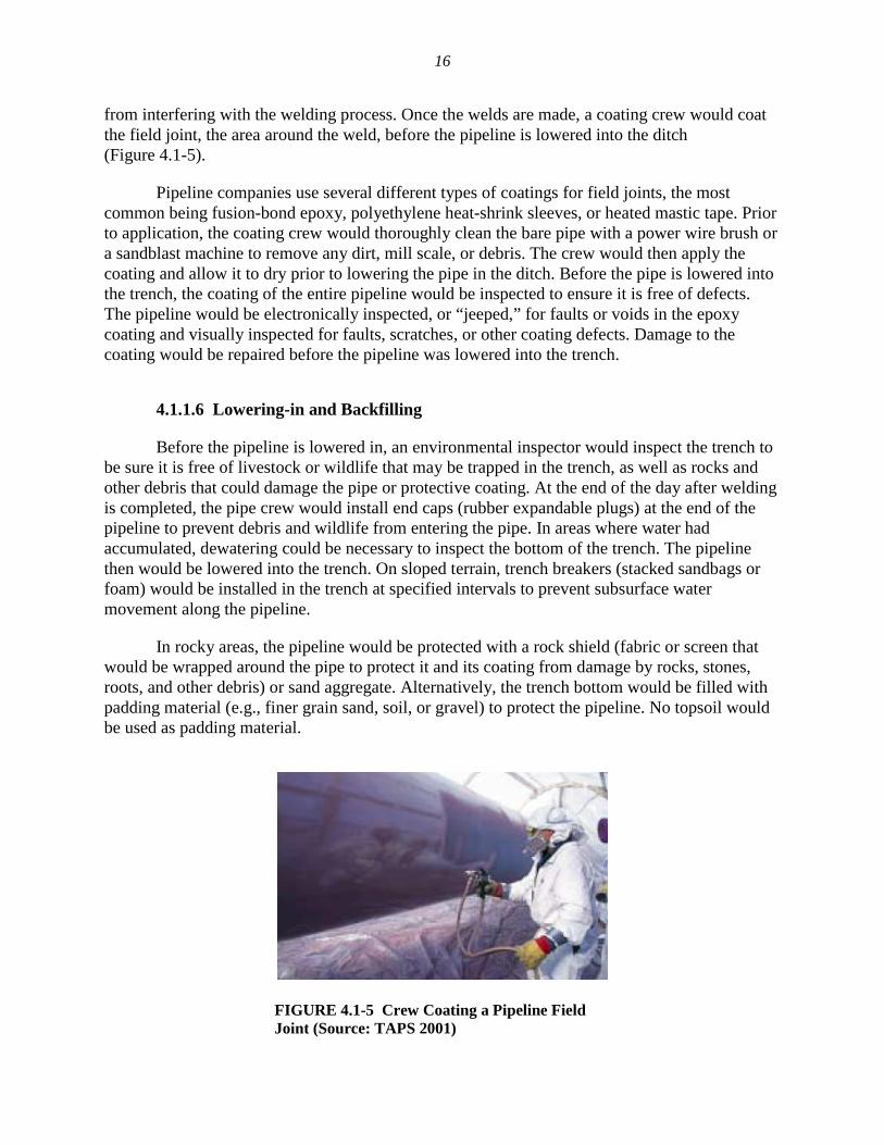
from interfering with the welding process. Once the welds are made, a coating crew would coat the field joint, the area around the weld, before the pipeline is lowered into the ditch (Figure 4.1-5). Pipeline companies use several different types of coatings for field joints, the most common being fusion-bond epoxy, polyethylene heat-shrink sleeves, or heated mastic tape. Prior to application, the coating crew would thoroughly clean the bare pipe with a power wire brush or a sandblast machine to remove any dirt, mill scale, or debris. The crew would then apply the coating and allow it to dry prior to lowering the pipe in the ditch. Before the pipe is lowered into the trench, the coating of the entire pipeline would be inspected to ensure it is free of defects. The pipeline would be electronically inspected, or “jeeped,” for faults or voids in the epoxy coating and visually inspected for faults, scratches, or other coating defects. Damage to the coating would be repaired before the pipeline was lowered into the trench.
4.1.1.6 Lowering-in and Backfilling Before the pipeline is lowered in, an environmental inspector would inspect the trench to be sure it is free of livestock or wildlife that may be trapped in the trench, as well as rocks and other debris that could damage the pipe or protective coating. At the end of the day after welding is completed, the pipe crew would install end caps (rubber expandable plugs) at the end of the pipeline to prevent debris and wildlife from entering the pipe. In areas where water had accumulated, dewatering could be necessary to inspect the bottom of the trench. The pipeline then would be lowered into the trench. On sloped terrain, trench breakers (stacked sandbags or foam) would be installed in the trench at specified intervals to prevent subsurface water movement along the pipeline. In rocky areas, the pipeline would be protected with a rock shield (fabric or screen that would be wrapped around the pipe to protect it and its coating from damage by rocks, stones, roots, and other debris) or sand aggregate. Alternatively, the trench bottom would be filled with padding material (e.g., finer grain sand, soil, or gravel) to protect the pipeline. No topsoil would be used as padding material.
FIGURE 4.1-5 Crew Coating a Pipeline Field Joint (Source: TAPS 2001)
17
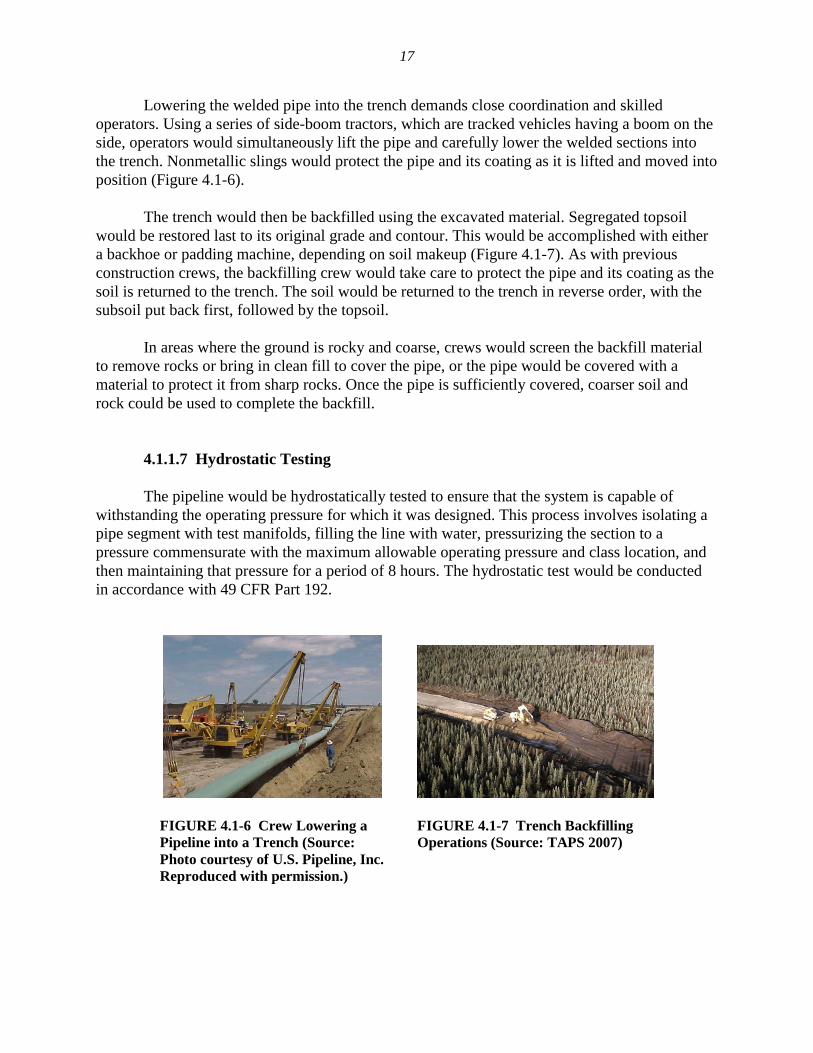
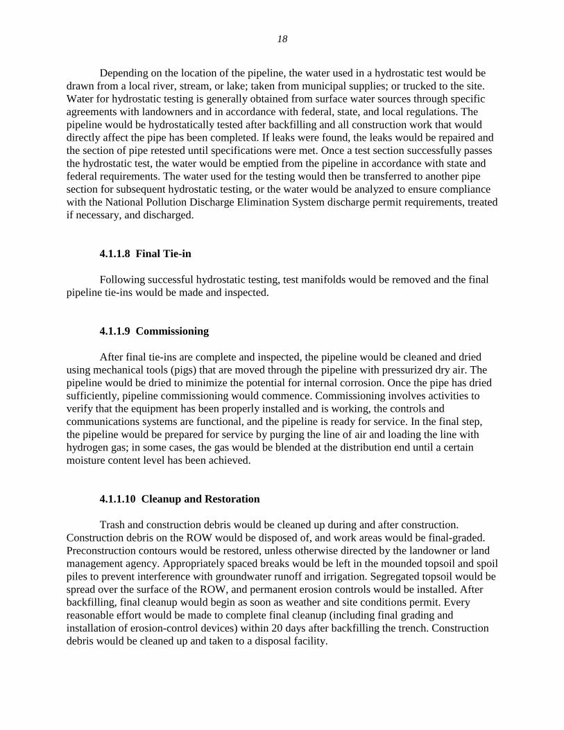
Lowering the welded pipe into the trench demands close coordination and skilled operators. Using a series of side-boom tractors, which are tracked vehicles having a boom on the side, operators would simultaneously lift the pipe and carefully lower the welded sections into the trench. Nonmetallic slings would protect the pipe and its coating as it is lifted and moved into position (Figure 4.1-6). The trench would then be backfilled using the excavated material. Segregated topsoil would be restored last to its original grade and contour. This would be accomplished with either a backhoe or padding machine, depending on soil makeup (Figure 4.1-7). As with previous construction crews, the backfilling crew would take care to protect the pipe and its coating as the soil is returned to the trench. The soil would be returned to the trench in reverse order, with the subsoil put back first, followed by the topsoil. In areas where the ground is rocky and coarse, crews would screen the backfill material to remove rocks or bring in clean fill to cover the pipe, or the pipe would be covered with a material to protect it from sharp rocks. Once the pipe is sufficiently covered, coarser soil and rock could be used to complete the backfill.
4.1.1.7 Hydrostatic Testing The pipeline would be hydrostatically tested to ensure that the system is capable of withstanding the operating pressure for which it was designed. This process involves isolating a pipe segment with test manifolds, filling the line with water, pressurizing the section to a pressure commensurate with the maximum allowable operating pressure and class location, and then maintaining that pressure for a period of 8 hours. The hydrostatic test would be conducted in accordance with 49 CFR Part 192.
FIGURE 4.1-6 Crew Lowering a Pipeline into a Trench (Source: Photo courtesy of U.S. Pipeline, Inc. Reproduced with permission.)
FIGURE 4.1-7 Trench Backfilling Operations (Source: TAPS 2007)
18
Depending on the location of the pipeline, the water used in a hydrostatic test would be drawn from a local river, stream, or lake; taken from municipal supplies; or trucked to the site. Water for hydrostatic testing is generally obtained from surface water sources through specific agreements with landowners and in accordance with federal, state, and local regulations. The pipeline would be hydrostatically tested after backfilling and all construction work that would directly affect the pipe has been completed. If leaks were found, the leaks would be repaired and the section of pipe retested until specifications were met. Once a test section successfully passes the hydrostatic test, the water would be emptied from the pipeline in accordance with state and federal requirements. The water used for the testing would then be transferred to another pipe section for subsequent hydrostatic testing, or the water would be analyzed to ensure compliance with the National Pollution Discharge Elimination System discharge permit requirements, treated if necessary, and discharged.
4.1.1.8 Final Tie-in Following successful hydrostatic testing, test manifolds would be removed and the final pipeline tie-ins would be made and inspected.
4.1.1.9 Commissioning After final tie-ins are complete and inspected, the pipeline would be cleaned and dried using mechanical tools (pigs) that are moved through the pipeline with pressurized dry air. The pipeline would be dried to minimize the potential for internal corrosion. Once the pipe has dried sufficiently, pipeline commissioning would commence. Commissioning involves activities to verify that the equipment has been properly installed and is working, the controls and communications systems are functional, and the pipeline is ready for service. In the final step, the pipeline would be prepared for service by purging the line of air and loading the line with hydrogen gas; in some cases, the gas would be blended at the distribution end until a certain moisture content level has been achieved.
4.1.1.10 Cleanup and Restoration Trash and construction debris would be cleaned up during and after construction. Construction debris on the ROW would be disposed of, and work areas would be final-graded. Preconstruction contours would be restored, unless otherwise directed by the landowner or land management agency. Appropriately spaced breaks would be left in the mounded topsoil and spoil piles to prevent interference with groundwater runoff and irrigation. Segregated topsoil would be spread over the surface of the ROW, and permanent erosion controls would be installed. After backfilling, final cleanup would begin as soon as weather and site conditions permit. Every reasonable effort would be made to complete final cleanup (including final grading and installation of erosion-control devices) within 20 days after backfilling the trench. Construction debris would be cleaned up and taken to a disposal facility.
19
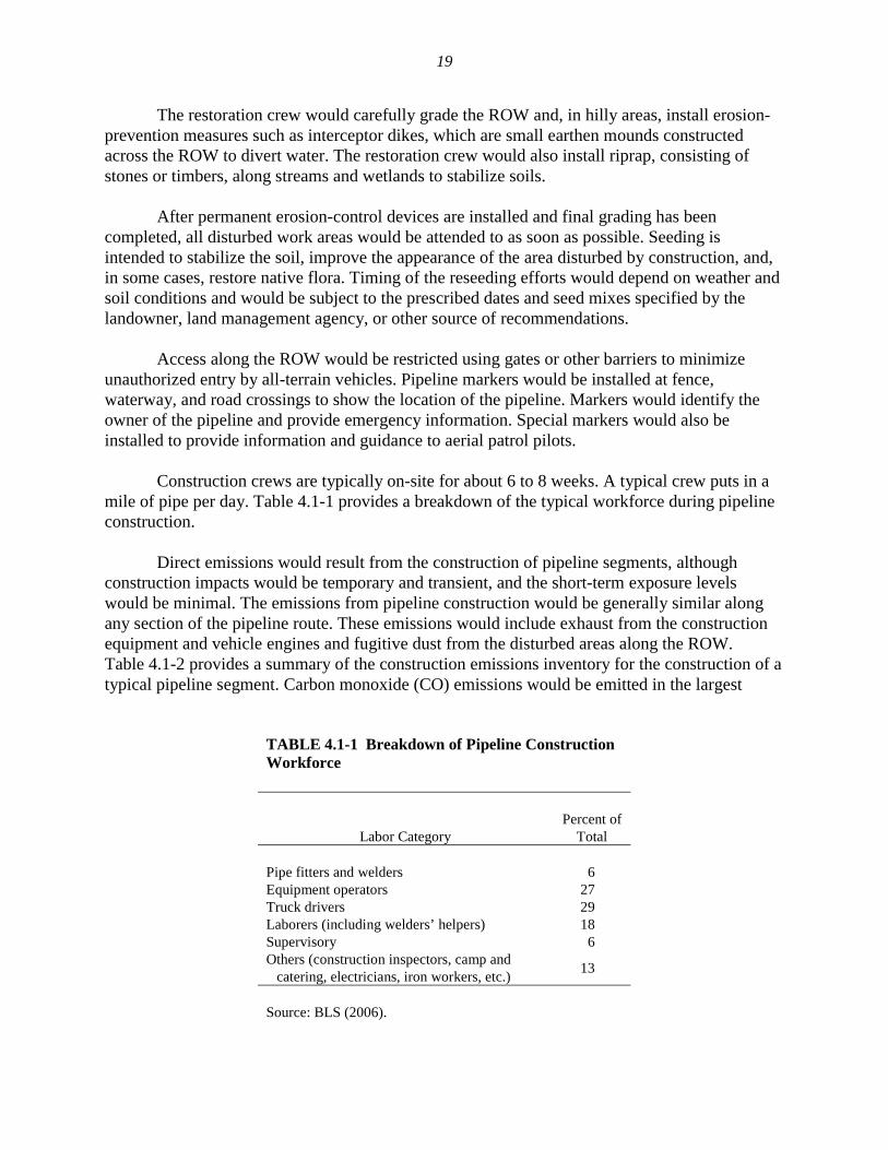
The restoration crew would carefully grade the ROW and, in hilly areas, install erosion-prevention measures such as interceptor dikes, which are small earthen mounds constructed across the ROW to divert water. The restoration crew would also install riprap, consisting of stones or timbers, along streams and wetlands to stabilize soils. After permanent erosion-control devices are installed and final grading has been completed, all disturbed work areas would be attended to as soon as possible. Seeding is intended to stabilize the soil, improve the appearance of the area disturbed by construction, and, in some cases, restore native flora. Timing of the reseeding efforts would depend on weather and soil conditions and would be subject to the prescribed dates and seed mixes specified by the landowner, land management agency, or other source of recommendations. Access along the ROW would be restricted using gates or other barriers to minimize unauthorized entry by all-terrain vehicles. Pipeline markers would be installed at fence, waterway, and road crossings to show the location of the pipeline. Markers would identify the owner of the pipeline and provide emergency information. Special markers would also be installed to provide information and guidance to aerial patrol pilots. Construction crews are typically on-site for about 6 to 8 weeks. A typical crew puts in a mile of pipe per day. Table 4.1-1 provides a breakdown of the typical workforce during pipeline construction. Direct emissions would result from the construction of pipeline segments, although construction impacts would be temporary and transient, and the short-term exposure levels would be minimal. The emissions from pipeline construction would be generally similar along any section of the pipeline route. These emissions would include exhaust from the construction equipment and vehicle engines and fugitive dust from the disturbed areas along the ROW. Table 4.1-2 provides a summary of the construction emissions inventory for the construction of a typical pipeline segment. Carbon monoxide (CO) emissions would be emitted in the largest
TABLE 4.1-1 Breakdown of Pipeline Construction Workforce
Labor Category
Percent of
Total Pipe fitters and welders 6 Equipment operators 27 Truck drivers 29 Laborers (including welders’ helpers) 18 Supervisory 6 Others (construction inspectors, camp and
catering, electricians, iron workers, etc.) 13
Source: BLS (2006).
20
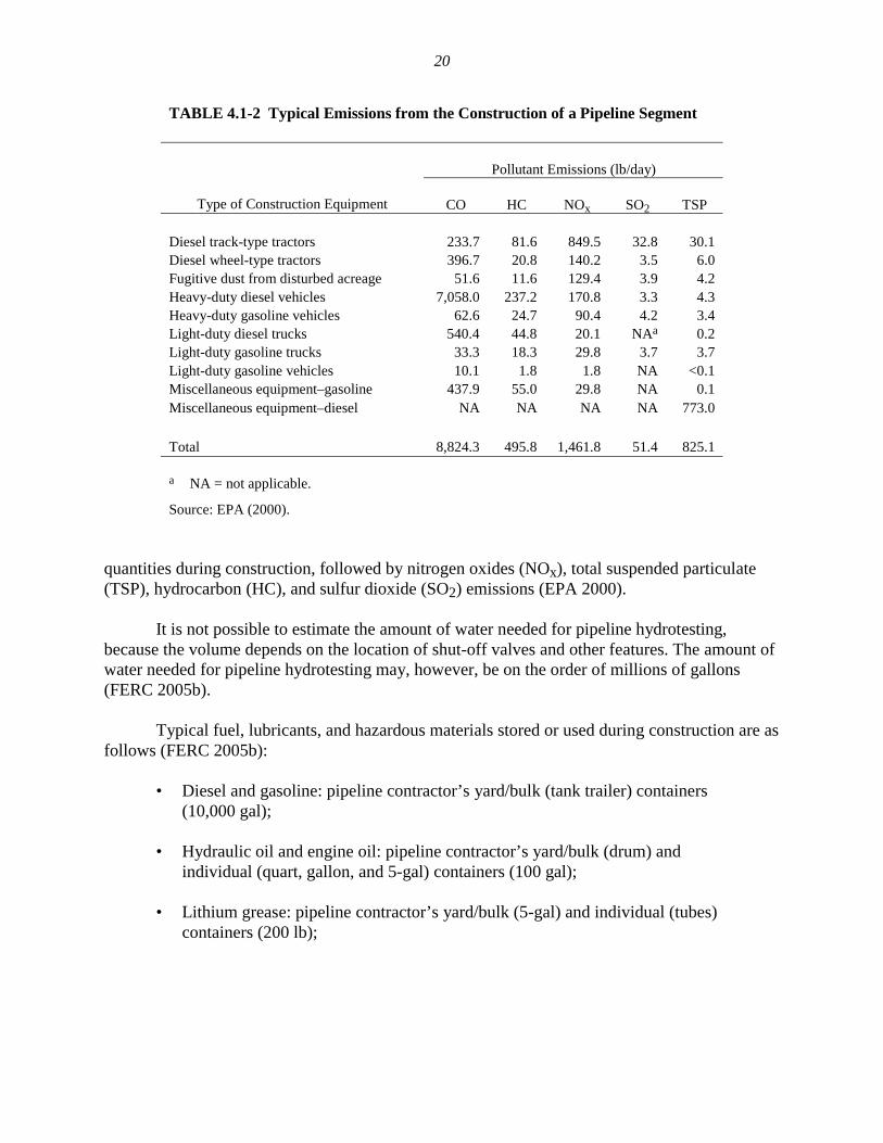
TABLE 4.1-2 Typical Emissions from the Construction of a Pipeline Segment
Pollutant Emissions (lb/day)
Type of Construction Equipment
CO HC NOx SO2 TSP Diesel track-type tractors 233.7 81.6 849.5 32.8 30.1 Diesel wheel-type tractors 396.7 20.8 140.2 3.5 6.0 Fugitive dust from disturbed acreage 51.6 11.6 129.4 3.9 4.2 Heavy-duty diesel vehicles 7,058.0 237.2 170.8 3.3 4.3 Heavy-duty gasoline vehicles 62.6 24.7 90.4 4.2 3.4 Light-duty diesel trucks 540.4 44.8 20.1 NAa 0.2 Light-duty gasoline trucks 33.3 18.3 29.8 3.7 3.7 Light-duty gasoline vehicles 10.1 1.8 1.8 NA <0.1 Miscellaneous equipment–gasoline 437.9 55.0 29.8 NA 0.1 Miscellaneous equipment–diesel NA NA NA NA 773.0 Total 8,824.3 495.8 1,461.8 51.4 825.1 a NA = not applicable.
Source: EPA (2000). quantities during construction, followed by nitrogen oxides (NOx), total suspended particulate (TSP), hydrocarbon (HC), and sulfur dioxide (SO2) emissions (EPA 2000). It is not possible to estimate the amount of water needed for pipeline hydrotesting, because the volume depends on the location of shut-off valves and other features. The amount of water needed for pipeline hydrotesting may, however, be on the order of millions of gallons (FERC 2005b). Typical fuel, lubricants, and hazardous materials stored or used during construction are as follows (FERC 2005b):
• Diesel and gasoline: pipeline contractor’s yard/bulk (tank trailer) containers (10,000 gal);
• Hydraulic oil and engine oil: pipeline contractor’s yard/bulk (drum) and
individual (quart, gallon, and 5-gal) containers (100 gal);
• Lithium grease: pipeline contractor’s yard/bulk (5-gal) and individual (tubes) containers (200 lb);
21
• Antifreeze: contractor’s/pipeline company’s yard/bulk (drum) and individual (gallon) containers (60 gal);
• Drilling mud (volume highly site-specific).
It should be noted that the above-listed fuels and lubricants are generally contained on a fuel truck that would service the construction equipment along the ROW. The typical capacities of the fuel truck are 2,000 gal of fuel, 55 gal each of hydraulic and engine oil, 50 lb of lithium grease, and 55 gal of antifreeze mix. Pipe and equipment yards are needed during pipeline construction, for temporary storage of pipe joints, mainline valves, etc. These yards would also be used by the contractor to stage personnel, equipment, new pipe, and other materials necessary for construction of the facilities, and could include contractor trailers, construction equipment, fuel/lubricants, and parking areas. These off-site pipe storage and contractor yards would typically consist of warehouses or open lots located in areas of existing commercial or industrial use. These yards typically range in size from 5 to 15 acres (FERC 2005a). All yards would be leased from willing landowners, and upon completion of construction activities, pipe storage, double joining, and contractor yards would be returned to their preconstruction condition and former usage. 4.1.2 Special Construction Procedures In addition to standard pipeline construction methods, special construction techniques would be used where warranted by site-specific conditions. These special techniques would be used when constructing across paved roads, highways, railroads, steep terrain, waterbodies, and wetlands, and when blasting through rock. These are described below. Additional construction areas, or temporary extra workspaces, would be required for construction at road crossings, railroad crossings, crossings of existing pipelines and utilities, stringing truck turnaround areas, wetland crossings, horizontal directional drilling (HDD) entrance and exit pits, and open-cut waterbody crossings. These extra workspaces would be located adjacent to the construction ROW and could be used for such things as spoil storage, staging, equipment movement, material stockpiles, and pull-string assembly associated with HDD installation. Individual extra workspaces would range in size from less than 0.1 acre to 2 acres. Extra workspaces would be returned to their preconstruction condition and former usage following completion of construction activities.
4.1.2.1 Road, Highway, and Railroad Crossings Construction across paved roads, highways, and railroads would be in accordance with the requirements of the appropriate road and railroad crossing permits and approvals obtained by the pipeline company. In general, major paved roads, highways, and railroads could be crossed by boring beneath the road or railroad. Boring requires the excavation of a pit on each side of the feature, the placement of boring equipment in the pit, then boring a hole under the road at least
22
equal to the diameter of the pipe. Once the hole is bored, a prefabricated pipe section would be pushed through the borehole, which would consist of either extra-heavy wall-thickness pipe or two pipes consisting of an outer casing pipe and an inner carrier pipe. For long crossings, sections could be welded onto the pipe string just before being pushed through the borehole. Boring would result in minimal or no disruption to traffic at road, highway, or railroad crossings. Each boring would be expected to take 2 to 10 days. Operations are typically 24 hours per day, 7 days per week until the boring is completed. Most smaller unpaved roads and driveways would be crossed using the open-cut method where permitted by local authorities or private owners. The open-cut method requires temporary closure of the road to traffic and establishment of detours. If no reasonable detour is feasible, at least one lane of traffic would be kept open, except during brief periods when it is essential to close the road to install the pipeline. Most open-cut road-crossing construction would be completed, including road resurfacing, on the order of weeks, depending on soil settlement after compaction. (In general, most pipeline companies would like to wait several weeks before final resurfacing.) Measures such as posting signs at open-cut road crossings would be undertaken to ensure safety and minimize traffic disruptions.
4.1.2.2 Steep Terrain Additional grading may be required in areas where the proposed pipeline route would cross steep slopes. Steep slopes often need to be graded down to a gentler slope to accommodate pipe-bending limitations. In such areas, the slopes would be cut away and, after the pipeline was installed, reconstructed to their original contours during restoration. In areas where the proposed pipeline route crosses laterally along the side of a slope, cut-and-fill grading may be required to obtain a safe, flat work terrace. Generally, on steep side slopes, soil from the high side of the ROW would be excavated and moved to the low side of the ROW to create a safe and level work terrace. Under these circumstances, the topsoil would be stripped from the entire width of the ROW. After the pipeline is installed, the soil from the low side of the ROW would be returned to the high side, topsoil replaced, and the slope’s original contours would be restored. In steep terrain, temporary sediment barriers such as a silt fence and certified weed-free straw bales would be installed during clearing to prevent the movement of disturbed soil off the ROW. Temporary slope breakers consisting of mounded and compacted soil would be installed across the ROW during grading, and permanent slope breakers would be installed during cleanup. Following construction, seed would be applied to steep slopes, and the ROW would be mulched with certified weed-free hay or nonbrittle straw, or covered with erosion-control fabric. Sediment barriers would be maintained across the ROW until permanent vegetation is established.
23
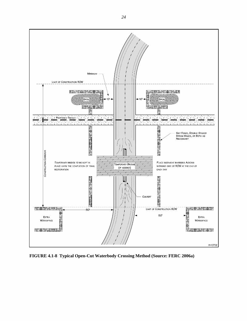
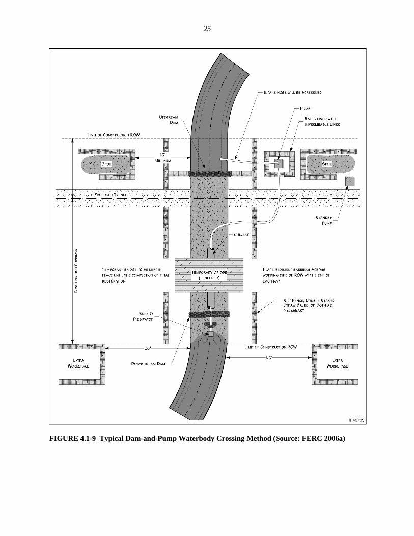
4.1.2.3 Waterbody Crossings The generally preferred method to cross a waterbody that is flowing at the time of construction would be HDD compared with the open-cut method, as the decreasing cost of HDD and its lack of environmental impact are making it more popular. The open-cut crossing method would involve trenching through the waterbody while water continues to flow through the trenching area. If no water were flowing at the time of construction, then the waterbody would be crossed using conventional upland cross-country construction techniques. The open-cut crossing method involves excavating a trench across the bottom of the river or stream to be crossed with the pipeline (Figure 4.1-8). Depending on the depth of the water, the construction equipment may have to be placed on barges or other floating platforms to excavate the pipe trench. If the water were shallow enough, the contractor could divert the water flow with dams and flume pipe to allow backhoes to dig the trench, working from the banks or the streambed. The contractor would prepare the pipe for the crossing by stringing it out on one side of the stream or river and then welding, coating, and hydrostatically testing the entire pipe segment. Side booms would carry the pipe segment into the stream bed, as they would for construction on land, or the construction crew would float the pipe into the river with flotation devices and position it for burial in the trench. Concrete weights or concrete coating ensure the pipe will stay in position at the bottom of the trench once the contractor removes the flotation devices. The flume, dam-and-pump, and HDD methods also could be considered as alternative crossing methods. The flume crossing method would involve diverting the flow of water across the trenching area through one or more flume pipes placed in the waterbody. The dam-and-pump method is similar to the flume method except that pumps and hoses would be used instead of flumes to move water around the construction work area (Figure 4.1-9). The HDD method would involve drilling a hole under the waterbody and installing a prefabricated segment of pipe through the hole. Before a directional drill can be designed, core samples must be taken on both sides of the crossing to evaluate the underground rock and sand formations. If the subsurface will support a directional drill, the engineer can design a crossing that establishes the entry point, the exit point, and the profile of the pipeline as it would traverse under the crossing. The HDD method involves drilling a pilot hole under the waterbody and banks, then enlarging the hole through successive reamings until the hole is large enough to accommodate a prefabricated segment of pipe. Throughout the process of drilling and enlarging the hole, a slurry made of nontoxic fluids, such as bentonite and water, would be circulated through the drilling tools to lubricate the drill bit, remove drill cuttings, and hold the hole open. This slurry is referred to as drilling mud. While this drilling is in progress, the line pipe sections are strung out on the far side of the crossing, to be welded. Once welded, the joints are X-rayed, coated, hydrostatically tested,
24
FIGURE 4.1-8 Typical Open-Cut Waterbody Crossing Method (Source: FERC 2006a)
25
FIGURE 4.1-9 Typical Dam-and-Pump Waterbody Crossing Method (Source: FERC 2006a)
26
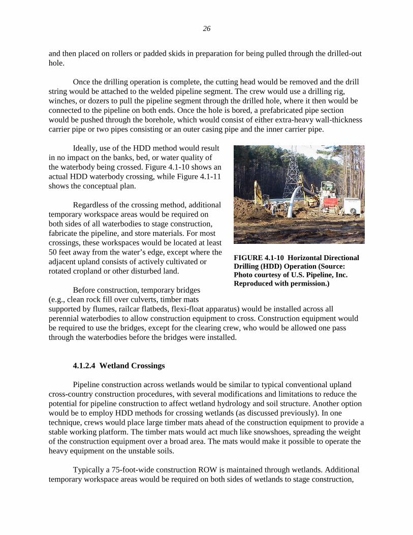
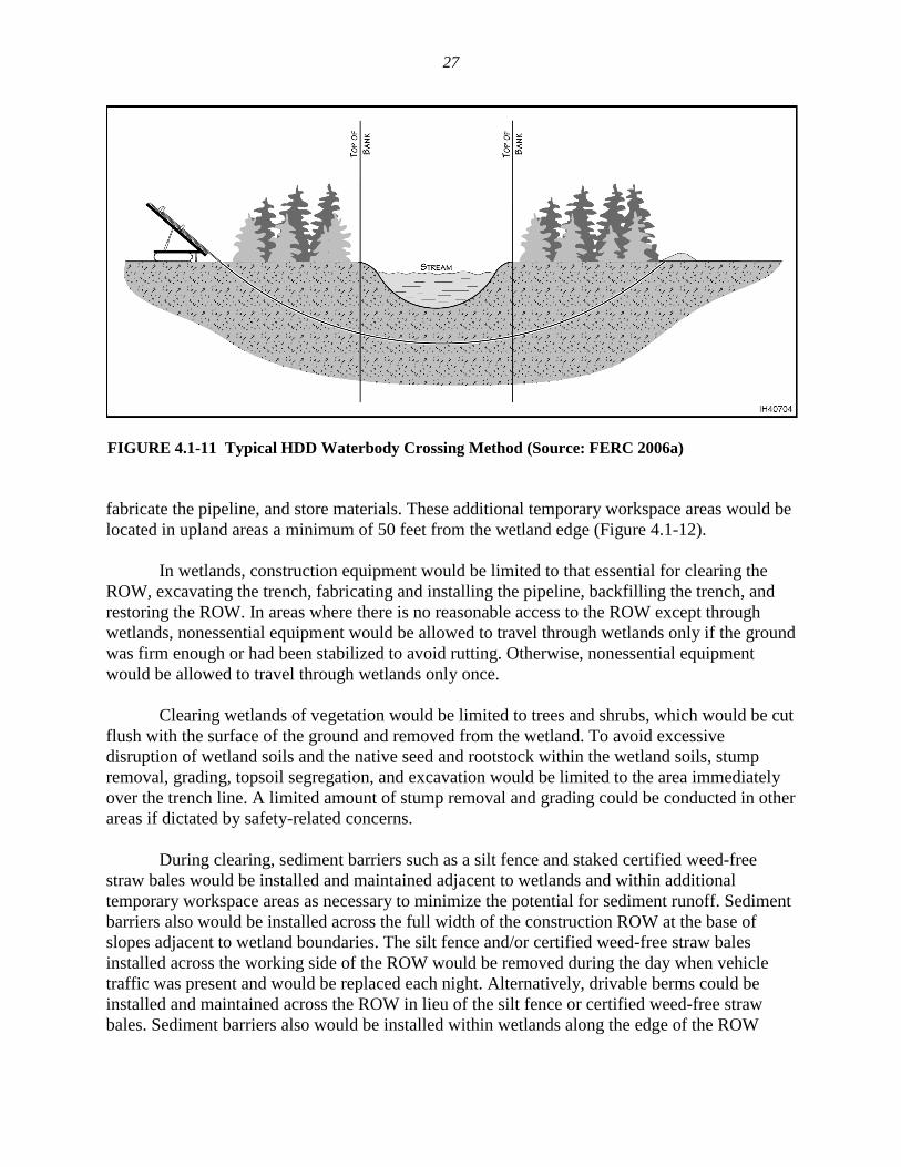
and then placed on rollers or padded skids in preparation for being pulled through the drilled-out hole. Once the drilling operation is complete, the cutting head would be removed and the drill string would be attached to the welded pipeline segment. The crew would use a drilling rig, winches, or dozers to pull the pipeline segment through the drilled hole, where it then would be connected to the pipeline on both ends. Once the hole is bored, a prefabricated pipe section would be pushed through the borehole, which would consist of either extra-heavy wall-thickness carrier pipe or two pipes consisting or an outer casing pipe and the inner carrier pipe. Ideally, use of the HDD method would result in no impact on the banks, bed, or water quality of the waterbody being crossed. Figure 4.1-10 shows an actual HDD waterbody crossing, while Figure 4.1-11 shows the conceptual plan. Regardless of the crossing method, additional temporary workspace areas would be required on both sides of all waterbodies to stage construction, fabricate the pipeline, and store materials. For most crossings, these workspaces would be located at least 50 feet away from the water’s edge, except where the adjacent upland consists of actively cultivated or rotated cropland or other disturbed land. Before construction, temporary bridges (e.g., clean rock fill over culverts, timber mats supported by flumes, railcar flatbeds, flexi-float apparatus) would be installed across all perennial waterbodies to allow construction equipment to cross. Construction equipment would be required to use the bridges, except for the clearing crew, who would be allowed one pass through the waterbodies before the bridges were installed.
4.1.2.4 Wetland Crossings Pipeline construction across wetlands would be similar to typical conventional upland cross-country construction procedures, with several modifications and limitations to reduce the potential for pipeline construction to affect wetland hydrology and soil structure. Another option would be to employ HDD methods for crossing wetlands (as discussed previously). In one technique, crews would place large timber mats ahead of the construction equipment to provide a stable working platform. The timber mats would act much like snowshoes, spreading the weight of the construction equipment over a broad area. The mats would make it possible to operate the heavy equipment on the unstable soils. Typically a 75-foot-wide construction ROW is maintained through wetlands. Additional temporary workspace areas would be required on both sides of wetlands to stage construction,
FIGURE 4.1-10 Horizontal Directional Drilling (HDD) Operation (Source: Photo courtesy of U.S. Pipeline, Inc. Reproduced with permission.)
27
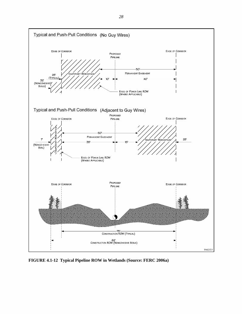
FIGURE 4.1-11 Typical HDD Waterbody Crossing Method (Source: FERC 2006a) fabricate the pipeline, and store materials. These additional temporary workspace areas would be located in upland areas a minimum of 50 feet from the wetland edge (Figure 4.1-12). In wetlands, construction equipment would be limited to that essential for clearing the ROW, excavating the trench, fabricating and installing the pipeline, backfilling the trench, and restoring the ROW. In areas where there is no reasonable access to the ROW except through wetlands, nonessential equipment would be allowed to travel through wetlands only if the ground was firm enough or had been stabilized to avoid rutting. Otherwise, nonessential equipment would be allowed to travel through wetlands only once. Clearing wetlands of vegetation would be limited to trees and shrubs, which would be cut flush with the surface of the ground and removed from the wetland. To avoid excessive disruption of wetland soils and the native seed and rootstock within the wetland soils, stump removal, grading, topsoil segregation, and excavation would be limited to the area immediately over the trench line. A limited amount of stump removal and grading could be conducted in other areas if dictated by safety-related concerns. During clearing, sediment barriers such as a silt fence and staked certified weed-free straw bales would be installed and maintained adjacent to wetlands and within additional temporary workspace areas as necessary to minimize the potential for sediment runoff. Sediment barriers also would be installed across the full width of the construction ROW at the base of slopes adjacent to wetland boundaries. The silt fence and/or certified weed-free straw bales installed across the working side of the ROW would be removed during the day when vehicle traffic was present and would be replaced each night. Alternatively, drivable berms could be installed and maintained across the ROW in lieu of the silt fence or certified weed-free straw bales. Sediment barriers also would be installed within wetlands along the edge of the ROW
28
FIGURE 4.1-12 Typical Pipeline ROW in Wetlands (Source: FERC 2006a)
29
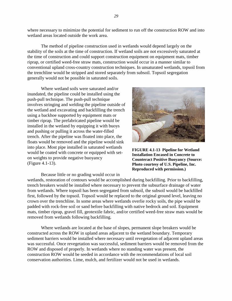
where necessary to minimize the potential for sediment to run off the construction ROW and into wetland areas located outside the work area. The method of pipeline construction used in wetlands would depend largely on the stability of the soils at the time of construction. If wetland soils are not excessively saturated at the time of construction and could support construction equipment on equipment mats, timber riprap, or certified weed-free straw mats, construction would occur in a manner similar to conventional upland cross-country construction techniques. In unsaturated wetlands, topsoil from the trenchline would be stripped and stored separately from subsoil. Topsoil segregation generally would not be possible in saturated soils. Where wetland soils were saturated and/or inundated, the pipeline could be installed using the push-pull technique. The push-pull technique involves stringing and welding the pipeline outside of the wetland and excavating and backfilling the trench using a backhoe supported by equipment mats or timber riprap. The prefabricated pipeline would be installed in the wetland by equipping it with buoys and pushing or pulling it across the water-filled trench. After the pipeline was floated into place, the floats would be removed and the pipeline would sink into place. Most pipe installed in saturated wetlands would be coated with concrete or equipped with set-on weights to provide negative buoyancy (Figure 4.1-13). Because little or no grading would occur in wetlands, restoration of contours would be accomplished during backfilling. Prior to backfilling, trench breakers would be installed where necessary to prevent the subsurface drainage of water from wetlands. Where topsoil has been segregated from subsoil, the subsoil would be backfilled first, followed by the topsoil. Topsoil would be replaced to the original ground level, leaving no crown over the trenchline. In some areas where wetlands overlie rocky soils, the pipe would be padded with rock-free soil or sand before backfilling with native bedrock and soil. Equipment mats, timber riprap, gravel fill, geotextile fabric, and/or certified weed-free straw mats would be removed from wetlands following backfilling. Where wetlands are located at the base of slopes, permanent slope breakers would be constructed across the ROW in upland areas adjacent to the wetland boundary. Temporary sediment barriers would be installed where necessary until revegetation of adjacent upland areas was successful. Once revegetation was successful, sediment barriers would be removed from the ROW and disposed of properly. In wetlands where no standing water was present, the construction ROW would be seeded in accordance with the recommendations of local soil conservation authorities. Lime, mulch, and fertilizer would not be used in wetlands.
FIGURE 4.1-13 Pipeline for Wetland Installation Encased in Concrete to Counteract Positive Buoyancy (Source: Photo courtesy of U.S. Pipeline, Inc. Reproduced with permission.)
30
4.1.2.5 Blasting If blasting were required to clear the ROW and to fracture the ditch, strict safety precautions would be followed. Extreme care would be exercised to avoid damage to underground structures, cables, conduits, pipelines, and underground watercourses or springs. To protect property or livestock, adequate notice would be provided to adjacent landowners or tenants in advance of blasting. Blasting activity would be performed during daylight hours and in compliance with federal, state, and local codes and ordinances and manufacturers’ prescribed safety procedures and industry practices. Blasting would not typically occur in streams except in areas where hard rock is encountered and HDD is uneconomical. After blasting, the remnants would be typically removed by backhoes or similar construction equipment.
4.1.2.6 Fences and Grazing Grazing permitees would be contacted prior to the start of construction and reclamation on their allotments. To prevent the passage of livestock, the opening in the fenceline would be temporarily closed when construction crews left the area. If gaps in natural barriers used for livestock control were created by pipeline construction, the gaps would be fenced according to the landowner’s or land management agency’s requirements. Whenever possible, a minimum of 10 feet of undisturbed area would be maintained where the pipeline paralleled a fenceline. All existing improvements, such as fences, gates, irrigation ditches, cattle guards, and reservoirs, would be maintained during construction and repaired to preconstruction conditions or better.
4.1.2.7 Rugged Topography
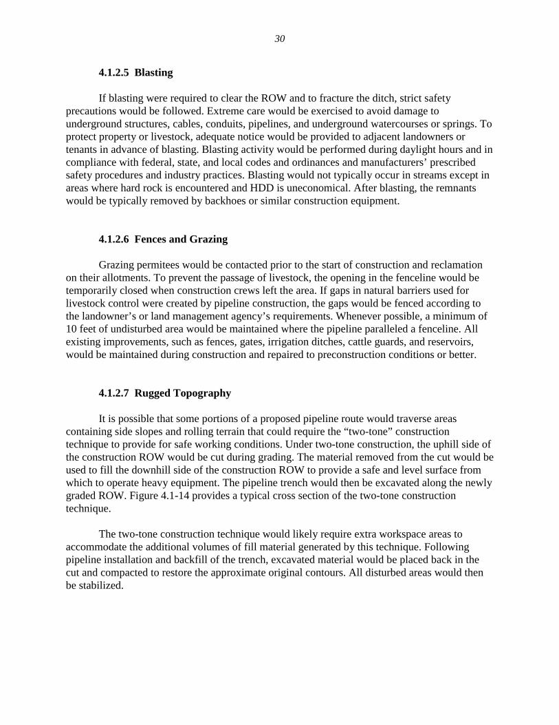
It is possible that some portions of a proposed pipeline route would traverse areas containing side slopes and rolling terrain that could require the “two-tone” construction technique to provide for safe working conditions. Under two-tone construction, the uphill side of the construction ROW would be cut during grading. The material removed from the cut would be used to fill the downhill side of the construction ROW to provide a safe and level surface from which to operate heavy equipment. The pipeline trench would then be excavated along the newly graded ROW. Figure 4.1-14 provides a typical cross section of the two-tone construction technique. The two-tone construction technique would likely require extra workspace areas to accommodate the additional volumes of fill material generated by this technique. Following pipeline installation and backfill of the trench, excavated material would be placed back in the cut and compacted to restore the approximate original contours. All disturbed areas would then be stabilized.
31
FIGURE 4.1-14 Typical Two-Tone Construction ROW (Source: FERC 2006b)
4.1.2.8 Construction Immediately Adjacent to Other Pipelines The existing pipeline company must be notified according to state law before construction begins in the vicinity of its facilities. This notification shall be made through the appropriate state One-Call notification service, but follow-up contact must be made to the existing pipeline company to seek approval for the proposed construction. Approved excavations above, below, or within 3 feet of either side of the pipeline shall be dug using hand tools. No construction or excavation activities of any kind, including blasting, shall be done on an existing pipeline’s ROW before its personnel have established the actual location of all affected facilities and the limits of the ROW. Personnel from the existing pipeline company would be present during any construction or excavation activities. The existing pipeline owner may require heavy equipment operators to install mats, dirt pads, or other approved protective materials to adequately protect pipelines from potential damage by heavy equipment crossing the ROW. All proposed road crossings of buried facilities would be evaluated by existing pipeline personnel. Any additional overburden would be removed after construction unless otherwise directed by the pipeline owner.
32
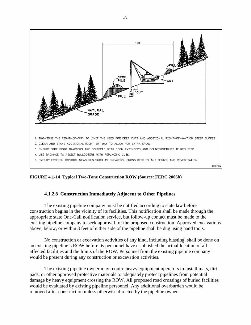
Figure 4.1-15 illustrates one potential construction ROW where a proposed pipeline would be located parallel to an existing pipeline (FERC 2005a). Any blasting proposed within 300 feet of existing pipeline facilities would be submitted to the attention of the existing pipeline owner in advance along with a blasting plan outlining the proposed activity. No blasting would begin unless the existing pipeline owner provides written confirmation that it does not object to such blasting. Any modifications to the blasting plan would also be submitted to the existing pipeline owner for review and would not be implemented unless it provided written confirmation that it does not object to such modifications. The blasting contractor may be required to monitor and record seismic shock at the existing facilities. A proposal for any directional drilling or boring under an existing pipeline’s buried facilities must be submitted to the existing pipeline company for review and approval. Adequate clearance should be maintained from the existing facilities, and additional excavations may be required to ensure adequate clearance. As-built plans are required for all borings. The existing pipeline company would be notified of any proposed construction or excavation within 300 feet in any direction of a hydrogen gas storage well. For safety, the
FIGURE 4.1-15 Typical Construction ROW When Adjacent to Existing Pipeline (FERC 2005a)
33
existing pipeline company would reserve the right to object to any such proposed activities or the placement of objects closer than 300 feet to a storage wellhead. Where possible, any proposed pipeline would be constructed 40 feet from the existing pipelines. In locations where this is not feasible, the new pipeline would be located within 20 feet or less of one or both of the existing pipelines, generally between the two existing pipelines. The pipeline company would contact the operator of the existing pipeline to restrict flows or reduce pressure in the existing pipeline during construction periods to allow heavy equipment to work over the existing line. Spoil from the ditch would be cast away from the existing pipeline, and no equipment would move back and forth over that particular pipeline. Once construction was completed, flows and/or pressures in the existing pipeline would resume at normal levels. 4.1.3 Aboveground Facility Construction Procedures The aboveground facilities would be constructed concurrent with pipeline installation, but construction would be conducted by special fabrication crews generally working separately from the pipeline construction spreads.
4.1.3.1 Compressor Stations Construction of compressor stations would involve clearing, grading, and compacting the sites to the surveyed elevations where necessary for placement of concrete foundations for buildings and to support skid-mounted equipment. Prefabricated segments of pipe, valves, fittings, and flanges would be shop- or site-welded and assembled at the compressor station site. The compressor units and other large equipment would be mounted on their respective foundations and the equipment micro-leveled to reduce vibration, and the compressor enclosures would be erected around them. Noise-abatement equipment (including sound-attenuating enclosures around the turbines, exhaust stack silencers, and air inlet silencers) and emission-control technology would be installed as needed to meet applicable federal, state, and/or local standards. Electrical, domestic water and septic, and communications utilities would be installed as necessary. Facility piping, both above and below ground, would be installed and hydrostatically tested before being placed in service. Controls and safety devices such as the emergency shutdown system, relief valves, gas and fire detection facilities, and other protection and safety devices would also be checked and tested. Upon completion of construction, all disturbed areas associated with the aboveground facilities would be finish-graded and seeded or covered with gravel, as appropriate. All roads and parking areas would be graveled. Additionally, the compressor station sites would be fenced for security and protection. Approximately less than one hundred workers and five inspectors would be required to construct a typical compressor station. Initial site preparation would typically take approximately 16 to 20 weeks, while actual installation would require more than 6 months. The lead time on purchasing some equipment such as compressors may be longer than 1 year.
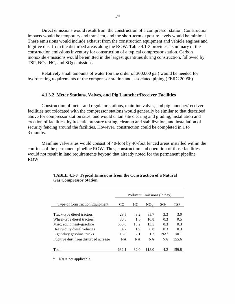
34
Direct emissions would result from the construction of a compressor station. Construction impacts would be temporary and transient, and the short-term exposure levels would be minimal. These emissions would include exhaust from the construction equipment and vehicle engines and fugitive dust from the disturbed areas along the ROW. Table 4.1-3 provides a summary of the construction emissions inventory for construction of a typical compressor station. Carbon monoxide emissions would be emitted in the largest quantities during construction, followed by TSP, NOx, HC, and SO2 emissions. Relatively small amounts of water (on the order of 300,000 gal) would be needed for hydrotesting requirements of the compressor station and associated piping (FERC 2005b).
4.1.3.2 Meter Stations, Valves, and Pig Launcher/Receiver Facilities Construction of meter and regulator stations, mainline valves, and pig launcher/receiver facilities not colocated with the compressor stations would generally be similar to that described above for compressor station sites, and would entail site clearing and grading, installation and erection of facilities, hydrostatic pressure testing, cleanup and stabilization, and installation of security fencing around the facilities. However, construction could be completed in 1 to 3 months. Mainline valve sites would consist of 40-foot by 40-foot fenced areas installed within the confines of the permanent pipeline ROW. Thus, construction and operation of those facilities would not result in land requirements beyond that already noted for the permanent pipeline ROW.
TABLE 4.1-3 Typical Emissions from the Construction of a Natural Gas Compressor Station
Pollutant Emissions (lb/day)
Type of Construction Equipment
CO HC NOx SO2 TSP Track-type diesel tractors 23.5 8.2 85.7 3.3 3.0 Wheel-type diesel tractors 30.5 1.6 10.8 0.3 0.5 Misc. equipment–gasoline 556.6 18.2 13.5 0.3 0.3 Heavy-duty diesel vehicles 4.7 1.9 6.8 0.3 0.3 Light-duty gasoline trucks 16.8 2.1 1.2 NAa <0.1 Fugitive dust from disturbed acreage NA NA NA NA 155.6 Total 632.1 32.0 118.0 4.2 159.8 a NA = not applicable.
35
Relatively small amounts of water (on the order of 100,000 gal) would be needed for hydrotesting requirements of the meter station and associated piping (FERC 2005b). On small sections of pipe, air or nitrogen may be used for hydrotesting.
4.1.3.3 Telecommunications Towers
Tower construction would involve erecting a 40-foot-tall, three-leg communications tower with associated microwave parabolic dish antennas and a self-contained 11-foot by 21-foot by 9-foot-tall concrete communications building on a simple slab foundation within a 40-foot by 60-foot (0.06 acre) area. A propane tank would be typically installed on the site to supply fuel to a backup emergency generator that would be located inside the building. The 40-foot by 60-foot area would be graveled and fenced.
4.1.3.4 Corrosion Protection and Detection Systems Corrosion in pipelines is a common phenomenon, and must be controlled to effectively prevent pipeline leaks or structural problems. Although modern pipes are constructed of high quality steel, this will nevertheless corrode over time. Corrosion results from an electrical current that naturally flows from a pipe into the surrounding soil. As this occurs, metal loss (corrosion) results. One way to impede this process would be to insulate the metal from the soil. This would occur in the manufacturing process when the pipe is coated. The coating would be rechecked at the construction site using a detector that looks for imperfections or gouges that could occur during transportation. A new coating would then be applied at the welded joints between pipe sections, by sandblasting the weld and then applying the new coat. A cathodic protection system would be installed to protect all underground and submerged pipeline facilities constructed of metallic materials from external, internal, and atmospheric corrosion. To further protect the pipeline from corrosion, rectifiers, anodes, or “ground beds” would be constructed at strategic points along the pipeline. These ground beds provide cathodic protection by inducing a very small electrical current into the soil, impeding the flow of electrons to the pipe. The rectifier that induces the current into the ground bed would be regularly checked by pipeline personnel, who ensure that the system is applying sufficient current to maintain cathodic protection to the pipeline. A single 200-foot ground bed could protect as much as 50 miles of pipeline, but the low voltages used would not harm animals or plants in the vicinity. Bonding would occur between separated pipelines and companies with a common ROW (the currents for all pipelines operate at the same level).
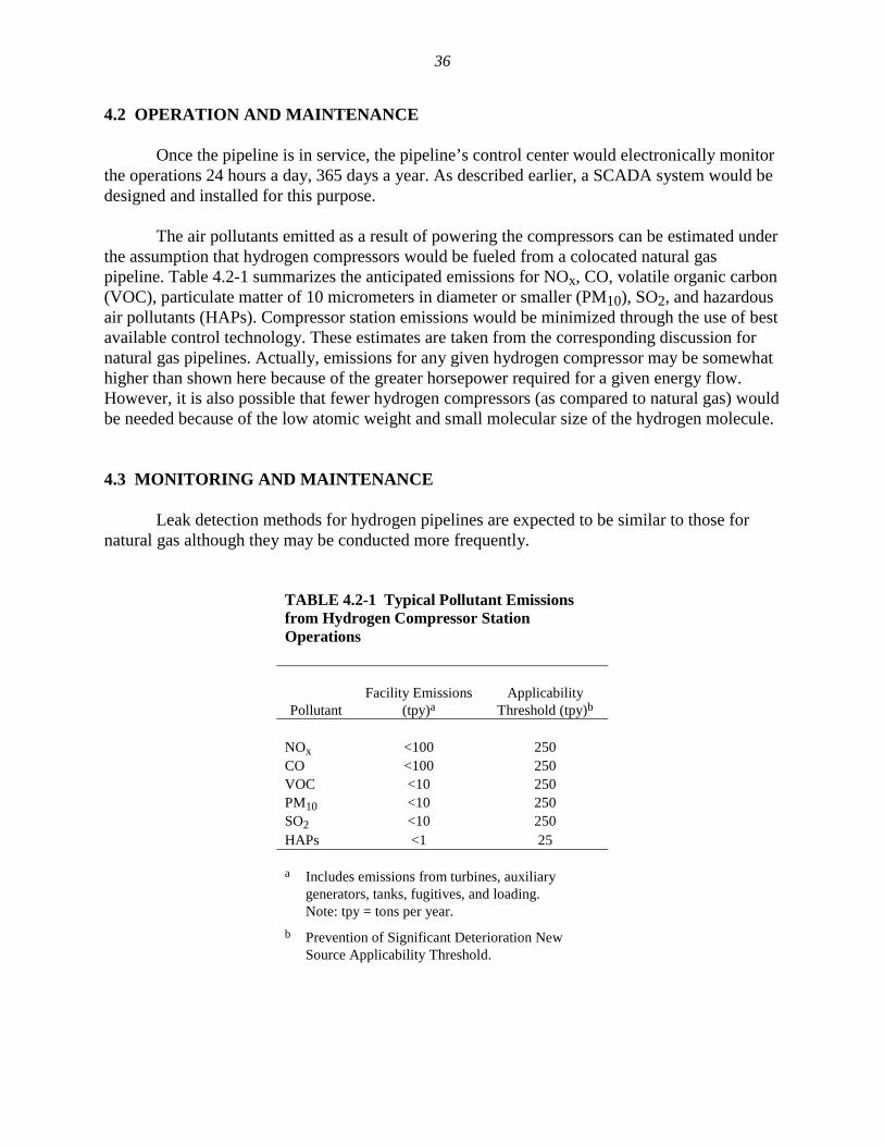
36
4.2 OPERATION AND MAINTENANCE Once the pipeline is in service, the pipeline’s control center would electronically monitor the operations 24 hours a day, 365 days a year. As described earlier, a SCADA system would be designed and installed for this purpose. The air pollutants emitted as a result of powering the compressors can be estimated under the assumption that hydrogen compressors would be fueled from a colocated natural gas pipeline. Table 4.2-1 summarizes the anticipated emissions for NOx, CO, volatile organic carbon (VOC), particulate matter of 10 micrometers in diameter or smaller (PM10), SO2, and hazardous air pollutants (HAPs). Compressor station emissions would be minimized through the use of best available control technology. These estimates are taken from the corresponding discussion for natural gas pipelines. Actually, emissions for any given hydrogen compressor may be somewhat higher than shown here because of the greater horsepower required for a given energy flow. However, it is also possible that fewer hydrogen compressors (as compared to natural gas) would be needed because of the low atomic weight and small molecular size of the hydrogen molecule. 4.3 MONITORING AND MAINTENANCE Leak detection methods for hydrogen pipelines are expected to be similar to those for natural gas although they may be conducted more frequently.
TABLE 4.2-1 Typical Pollutant Emissions from Hydrogen Compressor Station Operations
Pollutant
Facility Emissions
(tpy)a Applicability
Threshold (tpy)b NOx <100 250 CO <100 250 VOC <10 250 PM10 <10 250 SO2 <10 250 HAPs <1 25 a Includes emissions from turbines, auxiliary
generators, tanks, fugitives, and loading. Note: tpy = tons per year.
b Prevention of Significant Deterioration New Source Applicability Threshold.
37
Routine operation and maintenance would also be performed at all aboveground facilities in the same way as for natural gas facilities. Safety equipment, such as pressure-relief devices, fire detection and suppression systems, and gas detection systems would be maintained throughout the life of each facility. Mainline valves would also be inspected, serviced, and tested to ensure proper functioning. Vegetation management procedures would be exactly the same as for natural gas pipelines. 4.3.1 Pipeline Integrity In December 2002, President George W. Bush signed into law the Pipeline Safety Bill H.R. 3609, the Pipeline Safety Improvement Act of 2002. One of the provisions of the act required the Secretary of Transportation to issue regulations defining integrity management programs prescribing the standards for conducting a risk analysis and adoption and implementation of an integrity management program for natural gas pipelines. In December 2003, the DOT Office of Pipeline Safety issued a final rule requiring natural gas pipeline operators to develop integrity management programs for gas transmission pipelines located where a leak or rupture could do the most harm — that is, could impact high-consequence areas. The program is mandated by the DOT Office of Pipeline Safety and is part of federally mandated rules designed to improve the safety of natural gas distribution and transmission systems. It can be expected that hydrogen transmission pipelines would be subjected to the same requirements. 4.3.2 Future Plans and Abandonment Based on current, although limited, experience, hydrogen pipelines can be expected to have a useful lifetime of 50 years or more. However, in the event of project termination/ abandonment, the aboveground structures would typically be removed, while subsurface structures would be abandoned in place. This is the practice with natural gas pipelines, and it is anticipated that similar actions would be undertaken for hydrogen pipelines. 4.4 RELIABILITY AND CONGESTION ISSUES Insufficient infrastructure can cause pipeline congestion, temporarily forcing prices higher. There is little congestion on the natural gas pipeline network because investment in natural gas pipeline capacity has proceeded reasonably well in the United States. While an expansion in the hydrogen economy would result in a significant expansion of the pipeline infrastructure, it can be expected that the current FERC policies that have historically permitted gas pipeline owners allowed rates of return on equity that are at the high end of a zone of reasonableness will continue (Joskow 2005).

38
4.5 TRANSMISSION ENHANCEMENT TECHNOLOGY The U.S. Department of Energy and the private sector have multiple research and development programs intended to develop construction materials, constructional and operational practices, and appropriate safety codes and standards that would allow for the large-scale economic expansion of hydrogen use. These programs address many of the areas described in this report and would allow more definitive descriptions and quantitative evaluations of the consequences and benefits of widescale use of hydrogen pipelines in the United States.
39
5 REFERENCES Amos, W., 1998, Costs of Storing and Transporting Hydrogen, NREL/TP-570-25106, National Renewable Energy Laboratory, Golden, Colo., Nov. Available at http://www.nrel.gov/docs/ fy99osti/25106.pdf. Accessed March 9, 2007. BLS (Bureau of Labor Statistics), 2006, “Utilities,” U.S. Department of Labor, Washington, D.C. Available at http://www.bls.gov/oco/cg/cgs018.htm. Bossel, U., 2003, “The Physics of the Hydrogen Economy,” European Fuel Cell News, Vol. 10, No. 2, July. Drnevich, R., 2003, Hydrogen Delivery: Liquefaction & Compression, presented at Strategic Initiatives for Hydrogen Delivery Workshop, Tonawanda, N.Y., May 7. EPA (U.S. Environmental Protection Agency), 2000, Profile of the Oil and Gas Extraction Industry, EPA/310-R-99-006, Office of Compliance, October. Available at http://www.epa.gov/compliance/resources/publications/assistance/sectors/notebooks/oilgas.pdf. Accessed February 7, 2007. FERC (Federal Energy Regulatory Commission), 2005a, “Chapter 2: Proposed Action” in: FEIS on the Piceance Expansion Natural Gas Pipeline. Available at http://www.ferc.gov/industries/ gas/enviro/eis/2005/ 08-12-05.asp. Accessed March 8, 2007. FERC, 2005b, “Chapter 3: Environmental Analysis” in: FEIS on the Piceance Expansion Natural Gas Pipeline. Available at http://www.ferc.gov/industries/gas/enviro/eis/2005/08-12-05.asp. Accessed March 8, 2007. FERC, 2006a, Final Environmental Impact Statement on Cypress Pipeline Project and Phase VII Expansion Project, April 7. Available at http://www.ferc.gov/industries/gas/enviro/eis/2006/04-07-06.asp. Accessed March 12, 2007. FERC, 2006b, Draft Environmental Impact Statement for the Carthage to Perryville Project, May 26. Available at http://www.ferc.gov/industries/gas/enviro/eis/2006/05-26-06.asp. Accessed April 19, 2007. FERC, 2007, “Student’s Corner: Energy We Regulate.” Available at http://www.ferc.gov/ students/energyweregulate/gas.htm. Accessed February 7, 2007. Kreith, F., and R. West, 2004, “Fallacies of a Hydrogen Economy: A Critical Analysis of Hydrogen Production and Utilization,” Journal of Energy Resources Technology 126:249–257, Dec.
40
Joskow, P.L., 2005, Supply Security in Competitive Electricity and Natural Gas Markets, Massachusetts Institute of Technology, Dec. 29. Available at http://econ-www.mit.edu/faculty/download_pdf.php?id=1270. Accessed March 9, 2007. Mintz, M., S. Folga, J. Gillette, and J. Molburg, 2002, Hydrogen: On the Horizon or Just a Mirage?, presented at FutureCar Congress, Hyatt Crystal City, Va., June. Mohitpour, M., H. Solanky, and G. Vinjamuri, 2004, Materials Selection and Performance Criteria for Hydrogen pipeline Transmission, proceedings of the 2004 ASME/JSME Pressure Vessel & Piping Conference, San Diego, Calif., July 25–29. Oney, F., T.N. Veziroglu, and Z. Dulger, 1994, “Evaluation of Pipeline Transportation of Hydrogen and Natural Gas Mixtures,” International Journal of Hydrogen Energy 19(10):813–822. TAPS (Trans-Alaska Pipeline System), 2001, “Section 4.1: Mechanisms of Impact.” Available at http://tapseis.anl.gov/documents/docs/Section_4_1_May2.pdf. Accessed March 8, 2007. TAPS, 2007, “TAPS Construction Photo.” Available at http://tapseis.anl.gov/guide/photo/ construction.html. Accessed March 8, 2007.

A U.S. Department of Energy laboratory managed by UChicago Argonne, LLC
Environmental Science DivisionArgonne National Laboratory9700 South Cass Avenue, Bldg. 900 Argonne, IL 60439-4832
www.anl.gov