overview of mechanical properties of polymer‐matrix...
TRANSCRIPT

Overview of mechanical
properties of polymer‐matrix
composites
Dr. Suhasini Gururaja
Assistant Professor
Aerospace Engineering, IISc, Bangalore
1 Overview of Mechanical Properties for PMCs Dr. Suhasini Gururaja, AE, IISc Bangalore
(Parts of the material for this presentation has been borrowed from lecture notes of Prof. K. Lin and Dr. Patrick Stickler at University of Washington, Seattle. Some figures have been reproduced
from open literature and used here for purely pedagogical purposes.)

History Composite materials as a scientific/engineering discipline is
approximately 60 years old.
Composites have been useful for thousands of years
◦ Animal hair was added to pottery to improve strength
◦ Straw-reinforced clay was used to make bricks (Exodus
5:7)
◦ Bitumen was embedded with papyrus reeds to build boats
◦ Achilles’s shield was a composite laminate design (Homer’s
Illiad, xviii: 468-480)
Composite materials found in nature*:
◦ Wood: cellulose fibers in a lignin mating
◦ Bone: Collagen fibers in an apatite matrix
*Mechanical Design in Organisms, Wainwright et al, 1976.
2 Overview of Mechanical Properties for PMCs Dr. Suhasini Gururaja, AE, IISc Bangalore
What is a composite material?
Combination of two or more chemically distinct materials on the macroscopic scale tailored to achieve improved properties that neither constituents individually possess.
Improved properties achieved include ◦ Improved specific strength, stiffness, durability,
corrosion resistance etc.
Classification of composites ◦ Polymer Matrix Composites (PMCs)
◦ Metal Matrix Composites (MMCs)
◦ Ceramic Matrix Composites (CMCs)
Introduction
3 Overview of Mechanical Properties for PMCs Dr. Suhasini Gururaja, AE, IISc Bangalore

High Specific Strength (strength/density)
High Specific Stiffness (modulus/elasticity)
Tailored properties in load application direction
Tailored CTE for critical components
Excellent fatigue performance
Depending on resin/matrix combination and design
Corrosion resistant
UV resistant
Good dielectric
4 Overview of Mechanical Properties for PMCs Dr. Suhasini Gururaja, AE, IISc Bangalore
Potential structural advantages of
advanced composites

5 Overview of Mechanical Properties for PMCs Dr. Suhasini Gururaja, AE, IISc Bangalore
Specific property comparison

Key Differences between Composites and Metal
Anisotropy
Tailored Properties
Fatigue and Corrosion
Lighting protection
Discontinuous stresses
Delamination
Damage Tolerance
Environmental Effects
Repairability
Reduction in parts counts
6 Overview of Mechanical Properties for PMCs Dr. Suhasini Gururaja, AE, IISc Bangalore

Tailored Properties Composites
◦ Properties CAN be
tailored
Properties can be tailored by
combining different
percentages of 0o, 45o, -45o
and 90o plies
◦ Optimal use of
material
Material properties can be
tailored per loading
requirements to meet
design allowables while
reducing overall weight
Metals
◦ Properties CANNOT be tailored
Properties are represented in fixed values that cannot be tailored
◦ Material CANNOT be optimized
Structural performance can only be improved through changes in geometry, such as thickness, which adds to weight
7 Overview of Mechanical Properties for PMCs Dr. Suhasini Gururaja, AE, IISc Bangalore

Fatigue and corrosion
Composites
◦ Better fatigue
performance than metals
in tension (relatively flat
S-N curves)
◦ Compressive fatigue
properties are not as
good as those in tension
◦ Superior corrosion
resistance for CFRP
◦ Galvanic corrosion
occurs between CFRP
and Al, Mg, Cd plate and
steel.
Metals
◦ Relatively poor fatigue
properties in both
tension and
compression (more
steep S-N curve)
◦ Poor corrosion
resistance, especially in
a cracked structure
8 Overview of Mechanical Properties for PMCs Dr. Suhasini Gururaja, AE, IISc Bangalore

Discontinuous Stresses In-plane strains:
◦ Continuous throughout the
laminate thickness
Constant under uniform
extensional forces
Distributed linearly under
bending
In-plane stresses:
◦ Generally discontinuous
throughout the laminate
thickness because each ply
has different stiffness values
9
The strain-based design criteria are generally used in industry
Overview of Mechanical Properties for PMCs Dr. Suhasini Gururaja, AE, IISc Bangalore
Stresses due to
stretching Stresses due to
bending

Delamination
Occurs in laminated composites
Causes local bending and buckling in compressively loaded structures
Can grow under normal and shear loads
Careful designs needed at locations prone to delamination
10 Overview of Mechanical Properties for PMCs Dr. Suhasini Gururaja, AE, IISc Bangalore

Damage tolerance/Repairability
Critical damage
◦ Impact, delamination
◦ Compression after Impact (CAI)
strength is a key design parameter
Damage growth
◦ Complicated by multiple damage
types and failure modes
◦ Current design is for “no damage
growth”
Damage assessment is more difficult
– surface and internal damage
Most repairs are bonded repairs –
time consuming and require highly
skilled labor
Repair materials and adhesives are
time sensitive
Critical damage
◦ Fatigue crack, stress corrosion
Damage growth
◦ Crack growth can be reasonably
well predicted using fracture
mechanics approach
◦ Refer to FAR 25.571, “Damage
tolerance and fatigue evaluation
of structures”
Damage detection techniques are
well defined and surface damage
can be easily found
Most repairs are bolted repairs –
relatively easier and cheaper
No shelf life of repair materials
Quality of repair is easier to
control 11 Overview of Mechanical Properties for PMCs Dr. Suhasini Gururaja, AE, IISc Bangalore
Composites Metals

Environmental Effects/Thermal Stresses
12 Overview of Mechanical Properties for PMCs Dr. Suhasini Gururaja, AE, IISc Bangalore
Composite properties are strongly affected
by moisture, temperature, sunlight,
microbes, release agents, solvents etc.
Property reduction factors (knockdown
factors) are used appropriately
Due to mismatch in CTEs, thermal
residual stresses exist in structures.
Thermal stresses must be considered in
composite tool design and manufacturing.

Continuous fibers: lengths are in effect infinite -
Unidirectional Tape, Woven or braided Fabric
13
*Prof K. Lin AA532 Notes, University of Washington
Overview of Mechanical Properties for PMCs Dr. Suhasini Gururaja, AE, IISc Bangalore
Classifications of reinforcements
Whiskers, short fibers, and continuous fibers all have very small
diameters relative to their length (high aspect ratio)

Classifications of reinforcements Advanced composites
“modern”
◦ Particulates: roughly
spherical particles with
diameters (typically 1-100
mm)
◦ Whiskers: lengths <
10mm
◦ Short (or “chopped”)
fibers: length 10 – 100mm
SMC and Preforms
14 Overview of Mechanical Properties for PMCs Dr. Suhasini Gururaja, AE, IISc Bangalore

Laminate construction
Ready-to-cure part
on mandrel
Very good quality
Excellent
repeatability
Stacking cut plies
into a desired
sequence
15
~8mm dia
carbon fiber
127 mm ply
thickness
Fibers appear as ovals
because they were cut
at an angle to the 0º
direction.
*Prof K. Lin AA532 Notes, University of Washington Overview of Mechanical Properties for PMCs Dr. Suhasini Gururaja, AE, IISc Bangalore
Overview of Mechanical Properties for PMCs Dr. Suhasini Gururaja, AE, IISc Bangalore
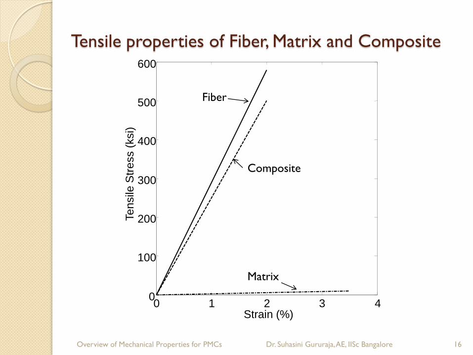
Tensile properties of Fiber, Matrix and Composite
16
0 1 2 3 4 0
100
200
300
400
500
600
Strain (%)
Te
nsile
Str
ess (
ksi)
Fiber
Composite
Matrix

Manufacturing Methods - Bag Molding Process
17
1. Mold surface covered with nonstick Teflon-coated glass fabric separator.
2. Prepreg plies laid up in desired fiber sequence and orientation.
3. Porous release cloth and a few layers of bleeder papers placed on top of prepreg stack.
4. Complete lay-up covered with another sheet of Teflon-coated glass fabric separator, caul plate, and thin,
heat-resistant vacuum bag.
5. Entire assembly placed inside autoclave where a combination of heat, external pressure, and vacuum is
applied to consolidate and densify separate plies into a solid laminate.
• Note: To prevent moisture pickup, prepreg roll on removal from cold storage should be warmed to room
temperature before use.
Overview of Mechanical Properties for PMCs, Dr. Suhasini Gururaja, AE, IISc Bangalore

Bag Molding Process Typical two-stage cure cycle for a carbon fiber-epoxy prepreg :
1. First stage
Increasing temperature up to 130°C (266°F).
Dwelling at this temperature for nearly 60 minutes until the minimum resin viscosity is reached.
During the temperature dwell, external pressure applied to prepreg stack that causes excess resin to flow out into bleeders.
2. End of temperature dwell
Autoclave temperature increased to actual curing temp. of resin.
Cure temperature and pressure maintained for 2 hours or more, until predetermined level of cure has occurred.
At end of cycle, temperature slowly reduced while laminate still under pressure.
Flow of excess resin from the prepreg is extremely important in reducing the void content in the cured laminate.
18 Overview of Mechanical Properties for PMCs, Dr. Suhasini Gururaja, AE, IISc Bangalore

Bag Molding Process
19
Typical two-stage cure cycle for a carbon fiber-epoxy prepreg
Overview of Mechanical Properties for PMCs, Dr. Suhasini Gururaja, AE, IISc Bangalore

Mechanical Properties of PMCs
“A material property” is a measurable
constant characteristic of a particular
material, which can be used to relate
disparate quantities of interest.
Key Mechanical properties include:
◦ Stress tensor to strain tensor
◦ Temperature/Moisture to strain tensor
◦ Stress (or strain) to failure/cycles to failure
◦ Crack growth to failure
20 Overview of Mechanical Properties for PMCs Dr. Suhasini Gururaja, AE, IISc Bangalore

Anisotropic behavior
Composites
◦ Anisotropic
Properties are dependent
upon directions
◦ Inhomogeneous
Properties are different in
different plies
◦ Mostly Brittle
Linear stress-strain relation
and low strain to failure
Metals
◦ Isotropic
Properties are the same in all
directions
◦ Homogeneous
Properties are the same in all
directions
◦ Mostly Ductile
Nonlinear stress-strain
relation with a large plastic
deformations
21 Overview of Mechanical Properties for PMCs Dr. Suhasini Gururaja, AE, IISc Bangalore

Anisotropic versus isotropic
22
x
y
z
Specimen 3
Specimen 1
Specimen 2
Three specimens machined at different orientations from a single “parent” block.
Overview of Mechanical Properties for PMCs Dr. Suhasini Gururaja, AE, IISc Bangalore

Anisotropic versus isotropic
23
Specimen 1 (Exx) Specimen 2 (Eyy) Specimen 3 (Ezz)
Tensile tests of three individual specimens
Overview of Mechanical Properties for PMCs Dr. Suhasini Gururaja, AE, IISc Bangalore

Anisotropic versus isotropic
Isotropic
Anisotropic
Anisotropic materials
◦ The value of Young’s modulus depends on the
direction within the material the modulus is
measured
◦ A similar dependence on direction can occur for
other mechanical properties (n’s, CTEs, ultimate
strengths, etc)
PMCs are anisotropic at the structural level
24
xx yy zzE E E
xx yy zzE E E
Overview of Mechanical Properties for PMCs Dr. Suhasini Gururaja, AE, IISc Bangalore
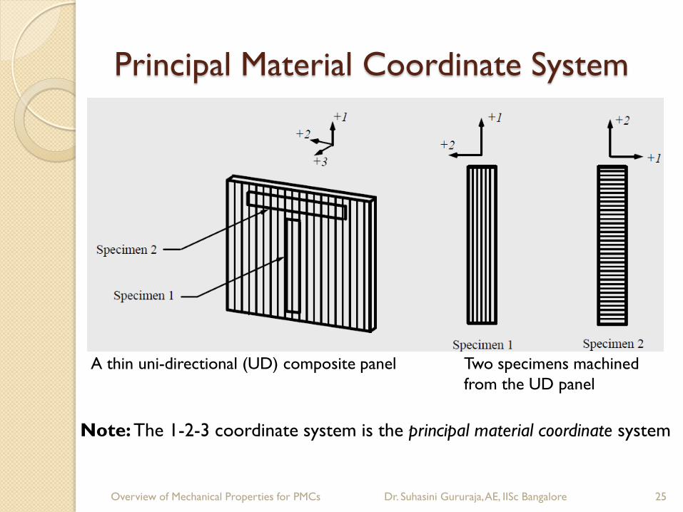
Principal Material Coordinate System
25 Overview of Mechanical Properties for PMCs Dr. Suhasini Gururaja, AE, IISc Bangalore
A thin uni-directional (UD) composite panel Two specimens machined
from the UD panel
Note: The 1-2-3 coordinate system is the principal material coordinate system
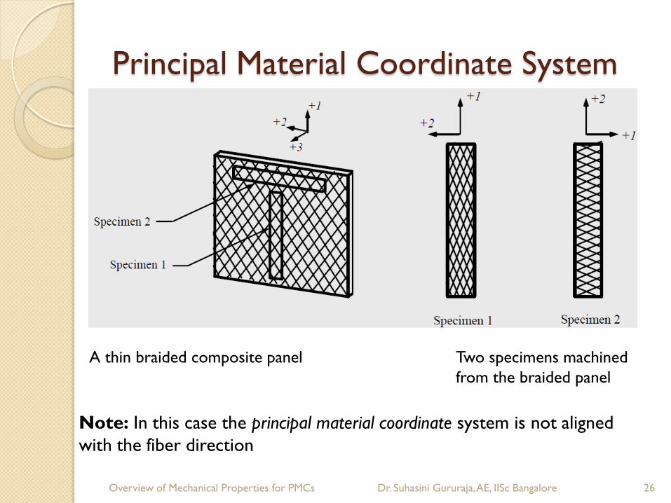
Principal Material Coordinate System
26 Overview of Mechanical Properties for PMCs Dr. Suhasini Gururaja, AE, IISc Bangalore
A thin braided composite panel Two specimens machined
from the braided panel
Note: In this case the principal material coordinate system is not aligned
with the fiber direction
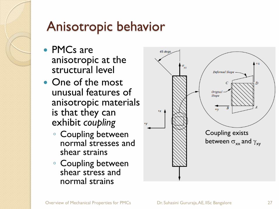
Anisotropic behavior
27 Overview of Mechanical Properties for PMCs Dr. Suhasini Gururaja, AE, IISc Bangalore
PMCs are anisotropic at the structural level
One of the most unusual features of anisotropic materials is that they can exhibit coupling ◦ Coupling between
normal stresses and shear strains
◦ Coupling between shear stress and normal strains
Coupling exists
between sxx and gxy

Coupling of bending and stretching deformations
The extensional force can cause shear deformation for unbalanced laminates
The extensional force can induce bending curvature for asymmetric laminates
A balanced laminate can develop twisting curvature under extensional forces
Unbalanced and asymmetric laminates result in a larger bending deformation, lower natural frequencies of vibration, and lower critical buckling loads.
28 Overview of Mechanical Properties for PMCs, Dr. Suhasini Gururaja, AE, IISc Bangalore

Uniaxial tensile test
29
*Vassilopoulos and Keller, Fatigue of FRCs, Springer, 2011
ASTM 3039
- Adhesively bonded tabs
Properties
- Ultimate Tensile Strength
- Ultimate tensile strain
- Modulus of Elasticity
- Poisson’s ratio

30
Designation Title
D3039 Standard Test Method for Tensile Properties of Polymer Matrix Composite
Materials
D5450 Standard Test Method for Transverse Tensile Properties of Hoop Wound
Polymer Matrix Composite Cylinders
D695 Standard Test Method for Compressive Properties of Rigid Plastics
D3410 Standard Test Method for Compressive Properties of Polymer Matrix
Composite Materials with unsupported Gage Section by Shear Loading
D5467 Standard Test Method for Compressive Properties of Unidirectional Polymer
Matrix Composites Using a Sandwich Beam
D5449 Standard Test Method for Transverse Compressive Properties of Hoop
Wound Polymer Matrix Composite Cylinders
D3518 Standard Practice for In-Plane Shear Response of Polymer Matrix
Composite Materials by Tensile Test of a 45°Laminate
D5379 Standard Test Method for Shear Properties of Composite Materials by the V-
Notched Beam Method
D4255 Standard Test Method for In-plane Shear Properties of Polymer Matrix
Composite Materials by the Rail Shear Method
D5448 Standard Test Method for In-plane Shear Properties of Hoop Wound
Polymer Matrix Composite Cylinders Overview of Mechanical Properties for PMCs Dr. Suhasini Gururaja, AE, IISc Bangalore

Yielding and Fracture of Composites
Predicting fracture of multiangle composite laminates under general load conditions remains a challenging area of research.
Three distinct "materials" regions may be defined ◦ The fiber
◦ The matrix
◦ The fiber-matrix interphase
The mechanical properties exhibited by the polymer in the interphase region differ from bulk properties.
The initial nonlinear deformations exhibited by a PMC are therefore almost entirely initiated within the polymeric matrix.
The fracture process is initiated when one or more microcracks are formed in the matrix.
31 Overview of Mechanical Properties for PMCs Dr. Suhasini Gururaja, AE, IISc Bangalore

Yielding and Fracture of Composites
Matrix Cracks ◦ Cracks that occur in the polymeric matrix, at some
distance from the fiber/matrix interface.
◦ Matrix cracks generally occur in planes either parallel or perpendicular to the fiber direction.
Fiber-Matrix Debonding ◦ The crack has formed in the interphase region, and a
(non-planar) crack extends around the periphery of the fiber.
Fiber Cracks ◦ Cracks that occur in the fiber itself.
◦ Fiber cracks almost always occur in a plane perpendicular to the axis of the fiber, and extend across the entire width of the fiber.
32 Overview of Mechanical Properties for PMCs Dr. Suhasini Gururaja, AE, IISc Bangalore
Yielding and Fracture of Composites
Viscoelastic behavior: yielding and crack growth in polymers is a time-dependent phenomenon called “creep”.
◦ An increase in temperature and/or an increase in moisture content further accentuate the time-dependency.
◦ If a tensile stress is applied and held constant the composite may eventually fail due to slow crack growth (often called a "creep-to-rupture" failure).
Chemical aging: polymers aging occurs due to ultra violate light.
33 Overview of Mechanical Properties for PMCs Dr. Suhasini Gururaja, AE, IISc Bangalore

Failure of Multi-angle Composite Laminate
Multi-angle laminates are subject to failure modes that do not exist in unidirectional laminates. ◦ The initiation of delamination failures is often
attributed to free-edge stresses.
◦ Free-edge stresses occur whenever adjacent plies possess differing Poisson ratios or coefficients of mutual influence.
Pre-existing thermal and/or moisture stresses occur in multi-angle laminates. ◦ Due to a mismatch in effective thermal expansion
and moisture expansion coefficients from one ply to the next.
34 Overview of Mechanical Properties for PMCs Dr. Suhasini Gururaja, AE, IISc Bangalore

Failure of Multi-angle Composite Laminate
Additional damage mechanisms in composites include: ◦ Fiber-matrix debonding: a crack forms around the
periphery of a fiber.
Load can no longer be transferred from the matrix to the fiber. ◦ Fiber micro-buckling: fibers within a ply that
experiences compressive stresses in the fiber direction buckle.
Reduces the compressive stiffness exhibited by the ply.
Leads to failure of the fibers due induced bending stresses.
35 Overview of Mechanical Properties for PMCs Dr. Suhasini Gururaja, AE, IISc Bangalore

Failure of Multi-angle Composite Laminate
Failure modes for multiangle laminates.
◦ Matrix cracking/splitting (microcracks).
◦ Delamination.
◦ Fiber fracture.
◦ Fiber/matrix debond.
◦ Fiber “kinking”(microbuckling).
◦ Global laminate buckling.
Failure should be verified experimentally.
36 Overview of Mechanical Properties for PMCs Dr. Suhasini Gururaja, AE, IISc Bangalore

Failure of Multi-angle Composite Laminate
Experimental observations of the evolution of damage in a quasi-isotropic laminate (monotonically increasing uniaxial load, Nxx)
37 Overview of Mechanical Properties for PMCs Dr. Suhasini Gururaja, AE, IISc Bangalore

Failure of Multi-angle Composite Laminate
The 90o plies yield as Nxx increases to a critical level.
Cracks begin to form in the 90o plies at load levels above the first-ply failure stress.
As the effective stress is further increased, cracks eventually begin to form within the ±45 plies
As the effective stress is increased further, delaminations begin to develop.
Matrix cracks begin to form between plies, and these new matrix cracks lie within planes that are parallel to the x-y plane
38 Overview of Mechanical Properties for PMCs Dr. Suhasini Gururaja, AE, IISc Bangalore

Failure of Multi-angle Composite Laminate
The delaminated regions grow in size as the stress is increased and eventually coalesce, such that a delaminated region may extend across the entire width of the specimen.
At still higher effective stress levels matrix cracks begin to form within the 0ºplies (often referred to as “splitting”).
These cracks lie within a plane perpendicular to the x-y plane.
Final laminate fracture is precipitated by fiber failures within the 0ºplies.
The effective stress level at which final fracture occurs is often called the last-ply failure stress.
◦ At final fracture the laminate fractures into fragments.
◦ Extensive and pre-existing matrix cracks and delamination that occurred at lower stress levels.
◦ Large amount of energy release associated with fiber failure.
39 Overview of Mechanical Properties for PMCs Dr. Suhasini Gururaja, AE, IISc Bangalore

Failure of Multi-angle Composite Laminate
Reifsnider et al studied damage progression of multi-angle composite laminates under fatigue loading. ◦ Material:
graphite/epoxy.
◦ Layup: [0/±45/90]s
◦ Tension-tension fatigue spectrum.
σmax= 0.62 σult
σmin= 0.062 σult
R = (σmin/ σmax) = 0.1
40 Overview of Mechanical Properties for PMCs Dr. Suhasini Gururaja, AE, IISc Bangalore
Nxx
0
s
Ds
smax
smin
sa sm

Failure of Multi-angle Composite Laminate
41 Overview of Mechanical Properties for PMCs Dr. Suhasini Gururaja, AE, IISc Bangalore
Experimental observations of damage
sequence under tension-tension fatigue
load spectrum.
◦ Matrix cracks in 90ºplies.
◦ Matrix cracks in ±45ºplies.
◦ Delaminations.
◦ Matrix cracks 0ºplies (splitting).
◦ Fiber failure.
◦ Final fracture.
Development of
characteristic damage state
Significant reduction in
stiffness.

Failure of Multi-angle Composite Laminate
42 Overview of Mechanical Properties for PMCs Dr. Suhasini Gururaja, AE, IISc Bangalore
Tension-tension fatigue Transverse Matrix Cracks

Constant Life Diagrams
43
0o 45o
90o
*Vassilopoulos and Keller, Fatigue of FRCs, Springer, 2011
ASTM E739-91

Case Study*: Tension-tension fatigue
properties of chopped GFRPs
44
SMC R27
SMC R37
Preform R25
Preform R40
Fatigue behavior of these four
Compression molded composites
shall be presented
Overview of Mechanical Properties for PMCs Dr. Suhasini Gururaja, AE, IISc Bangalore
*Results from T.Briggs and M. Ramulu, "An Experimental Characterization of the
Failure Mechanisms Activated in GFRP Composites" IMECE07, Seattle

Composite Material Composition
45
Material Component SMC-R27 SMC-R37
Resin base: PG Maleate/PVA low profile Polyester Polyester
Filler material Calcium Carbonate
(MgO thickeners)
Calcium Carbonate
(MgO thickeners)
Glass content by weight 27% 37%
Material Component Preform–R25 Preform-R40
Resin base w/LPA of thermoplastic Polyester Vinyl ester
Filler material Clay Calcium Carbonate
Glass content by weight. 25% 40%
Fine glass veil 0.76 mm thick 0.76 mm thick
Overview of Mechanical Properties for PMCs Dr. Suhasini Gururaja, AE, IISc Bangalore

Compression Molding Process
46
SMC Preform
Overview of Mechanical Properties for PMCs Dr. Suhasini Gururaja, AE, IISc Bangalore

Burn out Virgin Sample
47
x
y
SMC R-27 SMC R-37
PreForm - R25 PreForm – R40
Overview of Mechanical Properties for PMCs Dr. Suhasini Gururaja, AE, IISc Bangalore

UTS and tension-tension Fatigue Test Setup
48
Ambient air thermocouple Fatigue specimen
thermocouple
MTS 89-KN static tensile and tension-tension fatigue load frame
Overview of Mechanical Properties for PMCs Dr. Suhasini Gururaja, AE, IISc Bangalore
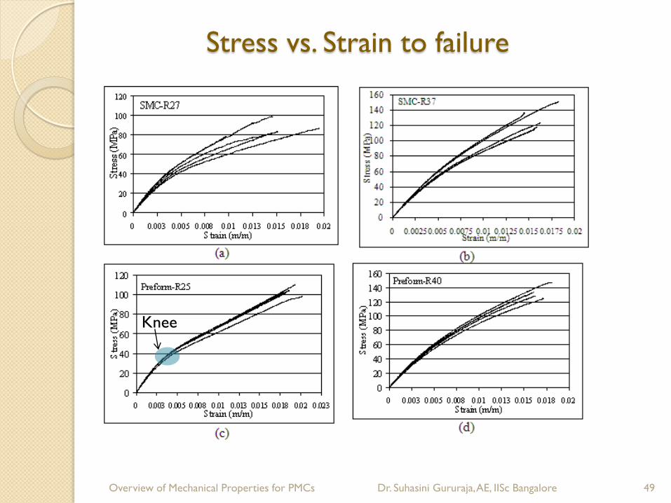
Stress vs. Strain to failure
49 Overview of Mechanical Properties for PMCs Dr. Suhasini Gururaja, AE, IISc Bangalore
Knee

Specimens after UTS Experiments
50
30 mm
SMC-R27
SMC-R37
Preform-R25
Preform-R40
Overview of Mechanical Properties for PMCs Dr. Suhasini Gururaja, AE, IISc Bangalore

Temperature versus Frequency
51
0
5
10
15
20
25
30
35
40
45
0 5 10 15 20 25 30 35 40 45 50 55 60 65
De
g C
Minutes
10 HZ
5 HZ
Overview of Mechanical Properties for PMCs Dr. Suhasini Gururaja, AE, IISc Bangalore
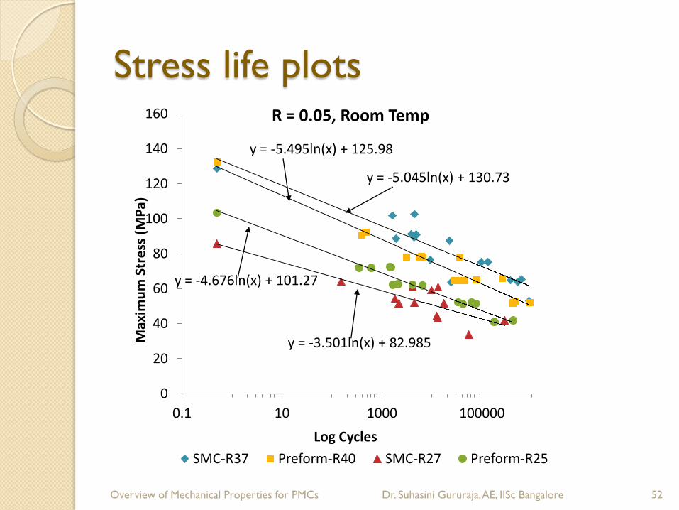
Stress life plots
52
y = -5.045ln(x) + 130.73
y = -5.495ln(x) + 125.98
y = -3.501ln(x) + 82.985
y = -4.676ln(x) + 101.27
0
20
40
60
80
100
120
140
160
0.1 10 1000 100000
Max
imu
m S
tre
ss (
MP
a)
Log Cycles
R = 0.05, Room Temp
SMC-R37 Preform-R40 SMC-R27 Preform-R25
Overview of Mechanical Properties for PMCs Dr. Suhasini Gururaja, AE, IISc Bangalore

Tensile Modulus degradation
53
100
102
104
106
5000
10000
15000
(a) SMC-R27Ten
sile
Mo
du
lus
(MP
a)
Log Cycles
70% UTS
60% UTS
50% UTS
40% UTS
30% UTS
100
102
104
106
5000
10000
15000
(b) SMC-R37
Ten
sile
Mo
du
lus
(MP
a)
Log Cycles
70% UTS
60% UTS
50% UTS
40% UTS
30% UTS
100
102
104
106
5000
10000
15000
(c) Preform-R25Ten
sile
Mo
du
lus
(MP
a)
Log Cycles
70% UTS
60% UTS
50% UTS
40% UTS
30% UTS
100
102
104
106
5,000
10,000
15000
(d) Preform-R40
Te
nsile
Mo
dulu
s (
MP
a)
Log Cycles
70% UTS
60% UTS
50% UTS
40% UTS
30% UTS
Overview of Mechanical Properties for PMCs Dr. Suhasini Gururaja, AE, IISc Bangalore

54
SMC-R27
SMC-R37
Preform-R25
Preform-R40
Fiber bundle
Pull-out
Matrix fracture
surface
Fiber
fracture
Fiber
bundle
damage
Fractography - 70% UTS fatigue test (R = 0.05)
Overview of Mechanical Properties for PMCs Dr. Suhasini Gururaja, AE, IISc Bangalore

55
Low-Velocity Impact
Effect of LVI on residual compression and tensile strengths of HTA/913 and HTA/982 CFRP laminates and E-glass/913
(normalized wrt undamaged material). [(±45,02)2]s (Courtesy: Brian Harris, Fatigue in Composites, CRC Press, 2003.)
Overview of Mechanical Properties for PMCs Dr. Suhasini Gururaja, AE, IISc Bangalore