owner's manualallows the idle threshold to be adjusted. the unit does not put out 120 volts...
TRANSCRIPT

XantrexFreedom 458 SeriesInverter/Charger
Owner's Manual
Freedom 4581015202530

2
SAFETY SUMMARYSafety information for installation andoperation is contained throughout thismanual where it applies and is not includedin this summary.
Definitions:
Warning statements identify conditions orpractices which could result in personal injury,loss of life, damage to equipment or otherproperty.
Fuse Replacement For continued protectionagainst the possibility of fire, replace the fuseonly with a fuse of the specified voltage,current and type ratings.
Power Source To avoid damage, operate theequipment only within the specified AC (line)and DC (battery) voltages.
Servicing To reduce the risk of electric shockdo not open this unit. There are no userserviceable parts inside. Refer all service toqualified personnel.
Thank you for purchasing a Xantrex Freedom 458 Series Inverter/Charger. XantrexTechnology Inc. takes pride in manufacturing quality products specificallydesigned to meet your power requirements.
Freedom 458 Inverter/Chargers provide silent, efficient and reliable AC power for avariety of applications. They feature �hands-free� operation, automatic three-stage batterycharging and automatic AC transfer switching. For your convenience, service is availableworld-wide from qualified service centers.
If you have any questions about your Freedom Inverter/Charger, please contactXantrex at 1-800-670-0707 (toll free) or 1-604-422-2777 (direct).
For technical support and additional information about Xantrex products, visit our Website at www.xantrex.com or e-mail us at [email protected]
Notice of CopyrightXantrex Freedom 458 Series Inverter/Charger © December 2002 Xantrex International. All rights reserved.Xantrex is a registered trademark of Xantrex International.
DisclaimerUNLESS SPECIFICALLY AGREED TO IN WRITING, XANTREX TECHNOLOGY INC. (�XANTREX�)
(a) MAKES NO WARRANTY AS TO THE ACCURACY, SUFFICIENCY OR SUITABILITY OF ANY TECHNICAL OR OTHERINFORMATION PROVIDED IN ITS MANUALS OR OTHER DOCUMENTATION.
(b) ASSUMES NO RESPONSIBILITY OR LIABILITY FOR LOSS OR DAMAGE, WHETHER DIRECT, INDIRECT,CONSEQUENTIAL OR INCIDENTAL, WHICH MIGHT ARISE OUT OF THE USE OF SUCH INFORMATION. THE USE OF ANYSUCH INFORMATION WILL BE ENTIRELY AT THE USER�S RISK.
Date and Revision December 2002, Revision 2 Part Number 445-0193-01-01
Contact Information Web: www.xantrex.com Email: [email protected] Phone: 1-800-670-0707 (toll free in North America), 1-604-422-2777 (direct) Fax: 1-604-420-2145

3
Introduction. . . . . . . . . . . . . . . . . . . . . . . . . 4Things You Should Know . . . . . . . . . . . . . 5
Circuit Breaker ProtectionThermostat Controlled CoolingInverter Idle CircuitLow and High Battery ShutdownPower SharingTemperature Sensitive Charging
Operation . . . . . . . . . . . . . . . . . . . . . . . . . . 7Optional Remote Control Panels . . . . . . . . .10Batteries . . . . . . . . . . . . . . . . . . . . . . . . . . 11
Battery TypesBattery InterconnectionBattery Bank Ratings and Sizing
Battery Charging. . . . . . . . . . . . . . . . . . . . 15Freedom Battery Chargers
Battery Charger Voltage Settings . . . . . . .20Installation Precautions . . . . . . . . . . . . . . 21Installation . . . . . . . . . . . . . . . . . . . . . . . . . 22
Key Installation PointsGroundingNeutral BondingAC WiringAC InputAC OutputGround Fault Circuit InterruptersRemote Control WiringTSC Temperature SensorDC WiringBattery Cable FusingPower ON Checks
TABLE OF CONTENTSTroubleshooting . . . . . . . . . . . . . . . . . . . . .31 LED Fault Status
Glossary . . . . . . . . . . . . . . . . . . . . . . . . . . . .33Specifications . . . . . . . . . . . . . . . . . . . . . . . . . 35Warranty . . . . . . . . . . . . . . . . . . . . . . . . . . . 36Installation Examples. . . . . . . . . . . . . . . . . . . 39
Not recommended for use in a marine environment
4
This owner�s manual describes theFreedom 458 Series Inverter/Chargers fromXantrex. These units perform three distinctfunctions:
1. DC to AC power inverting.2. Automatic transfer switching betweeninverter power and incoming AC power.3. Automatic three-stage battery chargingplus manual battery equalizing.
� The inverter provides regulated 120 volt ACpower at a crystal controlled frequency from adeep cycle battery bank and is rated at:
Freedom 10 1000 watts Freedom 15 & 15D 1500 watts Freedom 20 & 20D 2000 watts Freedom 25 2500 watts Freedom 30 3000 watts The output is a modified sine wave and iscompatible with most appliances, tools andother 120 VAC equipment. (Note: Certain laserprinters, breadmakers, digital clocks and smallbattery chargers may not operate on modifiedsine wave.) An idle mode reduces batterypower consumption when loads are removedfrom the inverter. There is a low battery cutoutprotection circuit and momentary surge powerof more than twice the inverter rating for start-ing electric motors. High efficiency ensures thelongest possible battery life between charges.
� The internal transfer switch allows theFreedom Inverter/Charger to be connected toan external AC source and transfer the sourcepower through directly to the loads. When theexternal AC power source is disconnected, thetransfer switch allows automatic switchingback to the inverter.
INTRODUCTIONThe Freedom Inverter/Charger operates
as a self-contained backup power system�just add batteries.
� Freedom battery chargers are electronicallycontrolled and rated at a maximum outputcurrent:
Freedom 10 50 amps DC Freedom 15 & 15D 75 amps DC Freedom 20 & 20D 100 amps DC Freedom 25 130 amps DC Freedom 30 140 amps DC
They are designed to rapidly and optimallycharge wet, gel, or Absorbed Glass Mat(AGM)** cell deep-cycle batteries. Batterycharging is automatically accomplished inthree stages: Bulk Charge, AcceptanceCharge and Float Charge.
Using a Remote Control Panel or LinkInstrumentation, a manually engagedEqualizing Charge cycle is possible. Simple,automatic operation is made possible by themicroprocessor in the Freedom Inverter/Charger.In most cases, no attention or maintenance isrequired.
Electronic ProtectionFast-acting electronic circuits protect
the inverter from overloads and short circuits.Other protection includes a low and highbattery voltage cutoff and automatic shutdownif an over-temperature condition occurs. Whenthe fault condition is corrected, the unit willautomatically reset. Example: removeoverload, charge batteries or allow to cool.
**Battery type selection is set on the front of the unitor with an optional remote (Remote Control Panel orLink Instrument).

5
Circuit Breaker ProtectionThe Freedom Inverter/Charger is supplemental breaker protected. The INVERT/CHARGE breaker on the frontof the unit protects against sustained inverter/charger over-current conditions. These breakers are reset by pushing thebutton back in. The output circuit breakers protect the outputAC circuits. Models are available with one ortwo outputs.Thermostat Controlled Cooling
Freedom Inverter/Chargers are equippedwith a thermostatically controlled fan that coolsthe unit so it can operate continually at its ratedunits with only supplemental circuit breakersbetween the unit and the load. Appropriate wiregauges must be used throughout the installation.Refer to NEC specifications.
THINGS YOU SHOULD KNOWInverter Idle Circuit
This automatic energy saving featurereduces battery power consumption when noAC load is present. Response from idle isinstantaneous. In most cases, the operation ofthe idle circuit is not noticeable. Use of theRemote Control Panel or Link Instrumentationallows the idle threshold to be adjusted. Theunit does not put out 120 volts when in idle. Tobring the unit out of the idle condition, apply aload.
Low and High Battery ShutdownWhen in invert mode, if the battery
voltage drops to 10.0 volts, the inverter willautomatically shut off. Charge the batteries to13.5 volts to automatically resume operation.
Voltage shutdown also occurs for a highbattery condition at 15.5 volts. Operation willresume automatically when the battery voltagedrops below 15.5 volts. Check all DC sourceson the system for the reason for the excessivevoltage.
Power SharingWhen connected to an external AC
source the battery charger and transferfunctions are engaged. A unique PowerSharing feature automatically reduces the ACpower consumption of the battery chargerallowing necessary AC power to go to the load.This prevents the source AC INPUT circuitbreaker from tripping within the specified ratingof the AC circuit breaker.
The Power Sharing set point of each unithas a factory default setting of 30 amps. Thiscan be changed using the Remote ControlPanel or Link Instrumentation.
25
Circuit Breaker ProtectionOUT 2
N/AN/A
15/20*N/A
15/20*N/AN/A
OUT 1N/AN/A
15/20*N/A
15/20*N/AN/A
INV/CHG15202025253030
101515D2020D2530
*Circuit breaker configurations include 15/15,15/20, and 20/20
*Note: Supplemental circuit breakers are resetby pushing the button back in. The fault must beremoved before resetting the circuit breaker. Inte-gral branch circuit rated breakers are reset bysetting the appropriate breaker switch to the �on�position. The fault must be removed before re-setting the circuit breaker. If a 30-ampere service supplies the input to theunit, a model with integral branch circuit ratedbreakers allows direct wiring from the unit to theload.

6
Temperature Sensitive Charging When the supplied battery temperaturesensor is connected to the unit and thebatteries, the charge voltage is controlledbased on battery temperature. The chargeradjusts the charge voltage to the best level,minimizing water loss in wet cell batteries.Charge voltage regulation optimizes the bat-tery life cycle.
THINGS YOU SHOULD KNOW
Branch Circuit Breakers
20 Amp
15 Amp
Shown:Freedom 20D81-2022-12
Freedom 458 Serieswith Branch Circuit Rated Breakers
Branch CircuitRated Breaker
Units with integral branch circuit ratedbreaker protection require a branch circuitrated breaker at the input only. The output totwo branch loads may be connected directlyat the unit output.
Branch CircuitRated Breaker
Inverter/Charger
Branch CircuitRated Breaker
INPUT
NOTE: The INPUT branch rated circuitbreaker may be at the source of AC power(such as shorepower or generator, or from amain AC distribution panel located beforethe input of the unit).
Inverter/Charger
INPUT To LOADS
Models10,15,20,25,30
*Models 25 and 30 include asecond input and output
TSC Sensor
Battery
SupplementalBranch Circuit Rated Breakers
Integral Branch Circuit Rated BreakersModels 15D&20D

7
OPERATIONThe Freedom 458 Inverter/Charger provides
120 volt AC power from auxiliary DC batteries,automatic battery charging and automatic ACtransfer switching between an external ACsource and inverter mode.
External AC PowerWhen external AC power is available, the
three-stage battery charger, transfer switching,and Power Sharing automatically function.
When external AC power is not availableand the INVERT switch is ON (either throughthe auxiliary switch or the INVERT button onthe remote), the inverter will automatically turnON. If the INVERT switch is OFF (the INVERTLED will not be illuminated), the inverter will beOFF.
If installed with the Remote Control Panelor Link Instrumentation, the unit will be set upand controlled from the remote. Refer to theremote manual for more information.
Front Panel Controls and Indicators
INVERT MODEThe INVERT push-button switch is
located on the front of the unit and has twofunctions:
� Turn the inverter ON/OFF and reset aftera fault condition. Pressing the INVERT switchturns the inverter ON. The green INVERT LEDwill be ON when the inverter is inverting. Whenthe inverter is ON, pressing the INVERT switchturns the inverter OFF.
INVERT
CHARGE
� Battery type setup. To enter the batterytype select mode, press and hold the INVERTswitch for five seconds. The status LEDs willchange from indicating status information toindicating battery type. The selection of thebattery type is made with the Charge switch.
Turning the INVERT OFF will reducebattery power consumption to a very low level.This is recommended if the unit will not beused for an extended period of time.
CHARGE MODEThe CHARGE push-button switch has
two functions:
� Turn the charger ON and OFFIf external AC is present, pressing theCHARGE switch will turn the charger ON.The green CHARGE LED will be ON when thecharger is charging. When the charger is ON,pressing this switch will turn the charger OFF.
� Select the battery typeAfter holding the INVERT switch for five seconds,press the CHARGE switch to select the batterytype. One of the four LEDs will rapidly blink,indicating the present battery type setting.Press the CHARGE switch again to changethe battery type. Continue to press until thedesired battery type is selected. If the CHARGEswitch is not pressed for five seconds, the unitwill return to normal operation and the batterytype selection will have been made.
When the 12-volt input to the unit isdisconnected, the battery type setting is storedin non-volatile memory. When the unit isreconnected, the battery type selectionconveniently returns to the setting.
Freedom 20

8
STATUS LEDsEach Status LED performs two functions,
providing battery type selection and operationstatus.
OPERATION
Operation Status
INVERT - Green LEDThe INVERT push-button switch is located onthe front of the unit.
� When the LED is solid green, the unit isin invert mode. This occurs by pressing theINVERT switch for (three to five seconds).
� When the LED is blinking slowly (onceper second), the inverter is in standby with ACpower applied and the transfer switch engaged
� Press the INVERT switch again to turnthe inverter OFF.CHARGE - Green LED
� The CHARGE push-button switch islocated on the front of the unit.
When external AC is applied to the ACinput of the unit, the charger automaticallyturns ON. The CHARGE LED will be solid green.
� When the LED is blinking slowly (onceper second), the charger is ready, but externalAC power is not available.
� Press the CHARGE switch again to turnthe charger OFF. The charger defaults to ONwhen operation without a remote or with theFreedom Remote Control Panel.
� When the LED is OFF, the charger hasbeen manually turned OFF. This can only beaccomplished while AC power is beingsupplied.
NOTE: When AC power is available, thedefault setting for the charger is ON. If the unitwas manually turned OFF and AC power isinterrupted and becomes available again, thecharger will return to ON.LOW BATTERY - Red LED
� When the LED is OFF the batteryvoltage is normal, between 10.5 and 15.0volts DC.
� When the LED is solid red, it indicates abattery warning condition, the battery voltage isbelow 10.5 volts DC or above 15.0 volts DC.
� When the LED is blinking slowly, (onceper second), a battery shutdown has occurred.The voltage is either below 10.0 volts DC orabove 15.5 volts DC.
� When the LED is blinking rapidly (fivetimes per second), a potential problem in theDC system has been detected. Check yourbatteries, battery cables and DC loads.
OVERTEMP/OVERLOAD - Red LED
� When the LED is Off, operation isnormal.
� When the LED is red, there is an overtemp or overload condition. Check forexcessive loads or a short circuit on the outputof the inverter. Correct the condition and restartby pushing the INVERT switch.
INVERT CHARGE REMOTE TSC
INVERT / WET
Battery Type Selection
After holding the INVERT button down forfive seconds, use the CHARGE button to selectbattery type:
WET GEL 1 GEL 2 AGM
CHARGE / GEL1LOW BATTERY / GEL 2
OVERTEMPOVERLOAD / AGM
Status LEDs

9
OPERATION� When the LED is blinking slowly (once
per second), an over-current condition or ashort circuit has occured. The system hasshut OFF and will not automatically restart.Correct the fault condition and manually restartthe system.
LOW BATTERY AND OVERTEMP/OVER-LOAD - Red LEDs
� When both LEDs are blinking, an ACbackfeed has been detected. A backfeedoccurs when AC power from an externalsource is connected to the output of theinverter. Inspect wiring for possible input/outputwiring error. This condition will damage the unitand must be corrected before furtheroperation.
TSC (Temperature Sensitive Charging)
This provides for the connection of asensor to measure battery temperature forcompensated charging. If no sensor isconnected the charge voltage levels are set todefaults based on battery type.
OPTIONAL REMOTES
If using one of the remotes, refer to theinstallation instructions included with theremote.
Note: When a Freedom Remote ControlPanel or Link is installed, the jumper includedin the parts plastic bag is not used in theAuxiliary Switch Port (AUX SWITCH) on thefront panel of the inverter/charger. See page 23for more details.
Remote TSC
OvertempLowBattery
Auxiliary Port

10
LINK 2000The Link 2000 has the same features as
the Link 1000, providing inverter/chargercontrol and complete battery state of chargeinformation. It monitors two battery banks.
OPTIONAL REMOTE CONTROL PANELSFreedom Remote Control Panel
An optional remote control panel isavailable. The LED bar graphs on the remotecontrol panel show battery voltage and DCcurrent in both inverter and charger modes.
Easy-to-see red, yellow and green LEDsshow the battery state of charge. PowerSharing, charger ON/OFF, inverter ON/OFFcontrols are provided. Setup features includeselection of Idle Threshold, Battery Type andBattery Capacity.
ADVANCED REMOTE CONTROL PANELSLink Instrument
Advanced remote control panels are alsoavailable: the Link 1000, 2000 and 2000-R.
LINK 1000Link 1000 controls the Freedom Inverter/
Charger and provides complete batterystate of charge information including DCvoltage, current, amp hours consumed, TimeRemaining and historical data for a singlebattery bank.
LINK 1000
LINK 2000
LINK 2000-RThe Link 2000-R adds the ability to
regulate an engine-driven alternator. Theprecision regulator in the Link 2000-R allowsthe alternator to be controlled as a three-stagebattery charging system.
If a Link Instrument is used to control theinverter/charger, refer to the Link Owner�sManual for setup and control information.
The jumper is not installed in the AUXSwitch Port on the front panel of theinverter when the Freedom RemoteControl Panel or Link Instrument is used.See page 23 for more details.
Refer to the Freedom Remote Control Panelor Link Owner�s Manual for
installation and operation instructions
Freedom Remote Control Panel

11
BATTERIES
BATTERY TYPESUse only deep-cycle batteries with your
Freedom Inverter/Charger. These fall into threebroad categories: wet cell, gel cell andAdvanced AGM (Absorbed Glass Mat)batteries.
Wet Cell BatteriesTrue deep-cycle wet cell batteries are
characterized by relatively thick internal platesthat are alloyed with antimony.
Common 12-volt marine/RV deep-cyclebatteries are acceptable. Golf cartbatteries perform well and may have alonger life. These 6-volt batteries must beused in series connected in pairs. Highquality deep-cycle batteries offer goodperformance and are available in a widevariety of sizes.
Wet cell batteries will give off gas as anatural result of charging and will experiencesome water loss. It is very important that theelectrolyte level be checked frequently andtopped off with distilled water when necessary.Follow the battery manufacturer�srecommendations for maintenance.
Never allow the top of the battery plates tobe exposed to air, as contamination of the cellwill result. Keep the top of batteries clean.Always provide adequate ventilation for thebattery storage compartment.
Do not use ordinary car batteries orengine starting batteries with your inverter/charger. Beware of any battery that is rated inCold Cranking Amps (CCA). This is a ratingwhich applies only to engine starting batteries.In general, most wet cell batteries that aredescribed as hybrid type batteries, suitable foreither engine starting or deep-cycleapplications are a compromise and will havelimited life if deeply discharged.

12
Beware of so-called maintenance-freebatteries. These batteries have calciumalloyed with the lead and hold the liquidelectrolyte in a sponge-like material. They aresealed and water cannot be added. Do notconfuse them with true gel cell or AGMbatteries�they will not hold up well to deepdischarging and repeated cycling.
Gel Cell BatteriesGel cell batteries are lead-acid batteries
similar in many ways to the common wet cellbattery, but differences in the chemistry andconstruction provide some unique features.
� No Maintenance
� Low Self-Discharge Rate
� Low Internal Resistance
Even though gel cells are sealedbatteries, the battery compartment should stillbe ventilated.
Advanced AGM (Absorbed Glass Mat)Batteries
This battery is lead acid but maintenance-free. The performance is similar to gel cellbatteries. The charge parameters are similarto wet cell batteries.
Battery SelectionThe most important feature to consider inmaking your battery selection is to select truedeep cycle batteries rated in amp hours (Ah)and sized to match your power requirements.
BATTERY INTERCONNECTIONIn most cases, you will be using a bank
of two or more batteries with your inverter/charger. You may connect batteries together intwo configurations�series and parallel�depending on their voltage.
BATTERIESSeries
Connecting two batteries in series willdouble the voltage of the battery bank. Forinstance, two 6-volt batteries connected inseries will produce 12 volts. The amp-hourcapacity of the battery bank will be the sameas each individual battery. Example, two 6-volt220 amp-hour batteries in series will produceone 12-volt 220 amp-hour battery bank.
Series
++
+
Series Increase Voltage
EACH BATTERYCAPACITY:
220AMP HOURS
@ 6 VDC
TOTAL BATTERYBANK CAPACITY:
220AMP HOURS@ 12 VDC
+ +
_ _
+
_6 V 6 V 12 V INVERTER

13
ParallelConnecting two batteries in parallel will
double the amp-hour rating of the battery bank,while the voltage will be the same as eachindividual battery. For example, two 12-volt 105amp-hour batteries in parallel will produce one12-volt 210 amp-hour battery bank.
BATTERIES
Parallel
Parallel Increase Amp-Hour Capacity
EACH BATTERYCAPACITY:
105AMP HOURS@ 12 VDC
TOTAL BATTERYBANK CAPACITY:
210AMP HOURS@ 12 VDC
Only similar batteries should beconnected together in one bank. Do notconnect old and new batteries together or wetand gel cell batteries together. In the abovedrawing, the load is connected to the positiveterminal of the first battery and the negativeterminal of the last battery. This practice helpsto balance the battery bank and is calledcross-connecting the battery bank.
Note: It is not advisable to connectbatteries of different case sizes or amp-hourratings in the same battery bank.
Always use properly sized wire andterminals for your interconnecting batterycables. For size information refer to NECrequirements or contact your localelectrician.
BATTERY BANK RATINGS AND SIZINGDeep-cycle batteries are usually rated in
amp hours. The amp-hour rating is based on a20-hour discharge rate; therefore, a 100amp-hour battery can deliver 5 amps for 20hours. If the discharge rate is greater than 5amps, the available amp hours are decreased.For example, if the load is increased to 100amps, only about 45 amp hours will be avail-able at this rate of discharge.
Deep-cycle batteries can be dischargedabout 80% of capacity before damage occurs.Shallow cycling will result in much longerbattery life. Calculating a battery bank sizebased on 50% discharge cycling is generallyconsidered to be a good compromise betweenlong battery life and size.
+ +
+ +
_
+
__12 V INVERTER12 V 12 V

14
To achieve 50% cycling you shouldcalculate your amp-hour consumptionbetween charging cycles and use a batterybank with twice that capacity**. Each ACappliance or tool has a rating plate on it and willbe rated in either AC amps or watts or AC VA(volt-amps) apparent power. To calculate amp-hour consumption, use one of the formulas tothe right to calculate the DC amp-hour draw fora 12-volt system.
Calculate the amp hours for every ACappliance or tool that will be operated on theinverter. This will provide the total number ofamp hours used between recharges. Size thebattery bank using this number as a guideline.A good rule to follow is to size the battery banka minimum of two times larger than thetotal amp-hour load requirement. Plan onrecharging when 50% discharged.
BATTERIES
(AC amps x 10) x 1.1 x hours ofoperation = DC amp hours
(watts/ DC voltage) x 1.1 x hours ofoperation = DC amp hours
(AC VA/ DC voltage) x 1.1 x hours ofoperation = DC amp hours
DC voltage is 12, 24 or 32 depending onyour system.
**Batteries are typically charged to 85% of fullcharge when charging with alternators without three-stage regulators.
Typical Power ConsumptlonThe chart identifies typical power
consumption for common AC loads. Use it asa guide when identifying your powerrequirements.
Many electric motors havemomentary starting requirementswell above their operational rating.Start up watts are listed whereappropriate. Individual styles andbrands of appliances may vary.
If using the same batterybank for the inverter and otherDC loads, be sure to considerthe power consumption of theDC loads when sizing thebattery bank.
noitpmusnoCrewoPlacipyT
ecnailppA lacipyTegattaW
sruoHpmA/semiTnuRecnailppA
.niM5 .niM51 .niM03 .rH1 .rH2 .rH3 .rH8 .rH42
VTroloC"31 05 33. 1 2 4 8 21 23 69
VTroloC"91 001 66. 2 4 8 61 42 46 291
RCV 05 33. 1 2 4 8 21 23 69
pmaL 001 66. 2 4 8 61 42 46 291
rednelB 003 2 6 21
retupmoCpotpaL 05 33. 1 2 4 8
norIgnilruC 05 33. 1 2
llirDrewoP8/3 005 3.3 01 02
*rekamecI 002 6.2 2.5 4.01 6.51 6.14 2.38
rekaMeeffoC 0001 6.6 02 04 08 061
*rotaregirfeR'uc3 051 2 4 8 21 23 69
*rotaregirfeR'uc02 057 12 24 48 621 633 276
evaworciMtcapmoC 057 5 51 03 06 021 081
evaworciMeziSlluF 0051 01 03 06 021 042 063
muucaV 0011 3.7 22 44 88 671 462
.semitnursuounitnocsuoiravnodesab)CDtlov21@(desusruohpmAlatotehtstneserperxobhcaenirebmuN.elycytud-3/1agnisudetaluclacyllacipytsinoitaregirferetoN*
In all formulas, 1.1 is the correction factor forinverter efficiency.
AMP-HOUR CONSUMPTION FORMULAS
NOTE Certain laser printers, breadmakers,digital clocks and appliance/tool chargersmay not operate on modified sine wave.

15
Battery ChargingCompletely charging wet cell deep-cycle
batteries requires the battery voltage to beraised beyond what is known as the gassingpoint. This is the voltage at which the batterybegins to bubble and gas is given off. Ifcharging stops short of this point, sulfate is lefton the plates and deterioration of the batterybegins. The gassing point will vary with batterytemperature.
At 77 °F, the gassing point of a 12-voltbattery is about 14.0 volts.
AGM and Gel cell batteries must not becharged to their gassing point. In fact, high-voltage charging that gasses these batteries isharmful to them. They typically require a lowerbulk charge voltage and a higher float voltagethan wet cell batteries. Consult the batterymanufacturer for specifications.
BATTERY CHARGINGFreedom Battery Chargers
Freedom battery chargers are designedto overcome the limitations of conventionalchargers by utilizing three distinct chargestages, each designed for optimal charging ofwet, gel cell and AGM deep-cycle batteries.Battery type selection is made on the frontpanel of the inverter/charger or through theFreedom Remote Control Panel or Link Instru-mentation. For more information on batterytype selection, see page 7 or refer to theFreedom Remote Control Panel manual.

16
BATTERY CHARGING
NOTE: Freedom battery chargers are ONwhenever AC power is connected to thecharger input. The charger can be turned OFFusing the CHARGE switch on the front of theunit. This sequence will occur each timeexternal AC power is available. The chargercan be turned ON/OFF using the RemoteControl Panel or Link Instrumentation.
Each time the battery charger is engaged,the three-stage charger proceeds automati-cally, resulting in an efficient complete chargeand safe battery maintenance. Use of theRemote Control Panel or Link Instrumentprovides the ability to periodically apply anequalizing charge.
Refer to the Remote Control Panel or theLink Instrument Owner�s Manual for moreinformation.
The battery charger stages are:Stage 1 - Bulk Charge During the bulk
charge stage most of the energy that hasbeen consumed during discharge is returnedto the battery bank. This phase is engaged assoon as the battery charger is activated. Fullrated charger current is delivered to thebattery bank until the acceptance chargevoltage limit is reached. This results in a relativelyrapid recharge.
Generally, a wet cell battery bank shouldnot be charged at a rate that exceeds 25% ofits capacity.

17
Gel cell and Advanced AGM batteries canaccept a higher rate of charge. Consult themanufacturer for specifications.
Stage 2 - Acceptance Charge Theacceptance stage immediately follows the bulkcharge stage. During this stage the batteryvoltage is held constant at the bulk chargevoltage limit and the current gradually rampsdown. During this stage the battery is acceptingits final amount of charge current and the lastof the sulfate on the plates is removed.
The acceptance stage lasts until thecharge current reaches the transition point. Atimer will terminate the acceptance stage if thiscurrent level is not reached.
BATTERY CHARGING
Maximum acceptance time is one hourfor wet and AGM cells and three hours for gelcells. Gel cell acceptance time can be longerbecause they are less likely to gas. Expect wetcell batteries to gas somewhat duringacceptance�this is a necessary part of thecharging process.
NOTE: The acceptance stage timer is notused when Link Instruments control thecharger. Refer to the Link Owner�s Manual.
Stage 3 - Float Charge When theacceptance stage is terminated, eitherbecause the charge current ramped down tothe transition point or the timer engaged, thecharge current will shut off. The unit monitorsthe battery voltage while it drifts down from theacceptance charge voltage limit. When itreaches the float voltage set point, the floatcharge stage is engaged.
The float charge stage holds the batteryvoltage constant at a preset lower level, whereit is safe for long-term battery maintenance.During the float charge stage, the full outputcurrent of the battery charger is available tooperate any DC appliances that may be on thesystem, while constantly maintaining the floatcharge voltage.
The battery charger remains in the floatcharge stage indefinitely until the charger isdisconnected from incoming AC power orturned OFF on the unit or with the FreedomRemote Control Panel or Link Instrumentation.
Stage 4 - Equalizing Charge This is theonly battery charger stage which is not engagedautomatically. It must be manually initiatedeach time. Applying an equalizing charge ispossible only with a Freedom Remote ControlPanel or Link Instrument.
Periodic equalizing is recommended bymost wet cell deep-cycle battery manufacturers.There are no firm rules for how often an equal-izing charge should be applied. Follow the batterymanufacturer�s recommendations for equalizing.
Freedom 10Freedom 15 & 15D
10 Ampere DC12 Ampere DC15 Ampere DC
ACCEPTANCE TO FLOAT TRANSITION POINTS
Freedom 20 & 20DFreedom 25Freedom 30
15 Ampere DC15 Ampere DC
18
BATTERY CHARGINGThe equalizing charge is a timed, eight-
hour cycle. The cycle can be ended early byinterrupting the AC power to the charger at anytime during the cycle. Equalizing should onlybe engaged after the batteries have been fullycharged by a normal battery charging cycle.
During this equalizing stage, the batteryvoltage will increase to the equalize voltage.This will cause the battery bank to gasprofusely and will accomplish the following:
1. Removal of residual sulfate. Each time abattery is cycled (discharged and charged), asmall amount of sulfate is left on the plates.Over time, this gradual build-up of sulfate willcompromise the performance of the battery.By applying an equalizing charge, the sulfate isreturned back to the electrolyte, raising thespecific gravity and fully exposing the activematerial of the plates.
2. Bring all cells to the same potential. Alllead-acid batteries are made up of individual2-volt cells. As the battery bank is cycled, slightdifferences in the cells result in different cellvoltages, affecting the overall chargeeffectiveness. Equalizing brings all cells to thesame voltage and the electrolyte in each cell tothe same specific gravity.
3. Mixing up of the electrolyte. Electrolyte inbattery cells tend to separate into layers of acidand water. The vigorous bubbling action of thebattery during equalizing serves to physicallymix the electrolyte. Refer to the RemoteControl Panel and Link Owner�s Manuals foradditional cautions on equalizing.
Note: Do not equalize gel cell batteries.

19
BATTERY CHARGING
1. Do not equalize gel cell batteries.Check remote default settings.
2. Always monitor the equalize chargecycle. Provide proper ventilation forbattery fumes. Do not allow any sparksduring equalizing. If one or more cellsbegin to overflow, terminate the equalizecycle.
3. Check the battery electrolyte bothbefore and after the equalizing charge.Do not expose the battery plates to air.Leave the battery caps on whileequalizing. Top off after equalizing.
4. Remove all loads from the DCsystem before equalizing. Some DCloads may not tolerate the high chargevoltage.
5. With the Freedom Remote ControlPanel the battery state-of-charge LEDssequence during equalizing. When theequalization cycle is complete, the chargeautomatically goes to float and the greenfloat LED battery status light is on. WithLink Instrumentation, the red chargeLED flashes during the equalizing cycle.When the equalization cycle is complete,the charger automatically goes to float andthe green float LED is illuminated.
WARNINGS

20
BATTERY CHARGER VOLTAGE SETTINGSPMET 0EPYT 1EPYT 2EPYT 3EPYT
lleCteW *1leG *2leG MGA
F° C° TPECCA TAOLF TPECCA TAOLF TPECCA TAOLF TPECCA TAOLF
021 94 5.21 5.21 0.31 0.31 0.31 0.31 9.21 9.21
011 34 6.31 7.21 5.31 0.31 0.41 4.31 9.31 9.21
001 83 8.31 9.21 7.31 2.31 1.41 5.31 0.41 0.31
09 23 0.41 1.31 8.31 3.31 2.41 6.31 1.41 1.31
08 72 2.41 3.31 0.41 5.31 3.41 7.31 2.41 2.31
**07 **12 4.41 5.31 1.41 6.31 4.41 8.31 3.41 3.31
06 61 6.41 7.31 3.41 8.31 5.41 9.31 4.41 4.31
05 01 8.41 9.31 4.41 9.31 6.41 0.41 5.41 5.31
04 5 0.51 1.41 6.41 1.41 7.41 1.41 6.41 6.31
03 1- 2.51 3.41 7.41 2.41 8.41 2.41 7.41 7.31
* There are two gel battery settings. Check with the battery manufacturer to determine theproper setting for your batteries. Usually, Gel 1 is for long battery life; Gel 2 is for rapid charging.**Default setting when the temperature sensor is not connected.

21
CAUTION This equipment is not ignitionprotected and employs components that canproduce arcs or sparks. To reduce the risk offire or explosions, do not install inunvented compartments containingbatteries or flammable gasses or areas inwhich ignition-protected equipment is required.
INSTALLATION PRECAUTIONS
For continued protection against risk ofelectric shock, use only the ground-faultcircuit interrupter (GFCI) type receptaclesdetailed in this manual. Other types mayfail to operate properly when connected tothis inverter, resulting in a potential shockhazard.
WARNING
CAUTION To reduce the risk of electric shockand prevent premature failure due to corrosion,do not mount where exposed to rain,dripping or spray.
CAUTION To reduce the risk of fire, do notobstruct ventilation openings. Do not mountin a zero-clearance compartment�overheating may result.
CAUTION Risk of electrical shock. BothAC and DC voltage sources areterminated inside this equipment. Beforeservicing disconnect all inputs and outputs.
Typical Tools NeededFlathead and Phillips ScrewdriversAllen (Hex) Screwdriver (1/8'')Wrench for connecting battery cables (9/16'')Wire CuttersWire StrippersMisc. assortment of wire ties and connectors
Accessories Needed for InstallationFuse: UL Listed DC Rated slow blow fuse asrequired by NECElectrical wire (10 gauge) for AC input wiring. Consult NEC for proper size for output wiring.Battery Cables 1-Positive, 1-Negative Consult NEC for proper sizeDC fuse cableMounting Screws (4)
Confirm that your shipping carton contains:
� Inverter/Charger� TSC temperature sensor with 15' cable� Owner�s Manual� Warranty Card� Jumper for AUX Switch (only used without
Remote Control Panel or Link Instrument)� Wire Nuts
The Freedom 15D and 20D havedual AC Outputs.
Freedom 20

22
CAUTION Risk of electrical shock. Do notremove cover, no user serviceable partsinside. Refer servicing to qualified servicepersonnel.
The Freedom 458 Inverter/Charger isappropriate for installation in recreationalvehicles (RV) and other applications.
It is recommended that installation becompleted by an authorized Xantrex technicaldealer or experienced electrician.
Key Installation Points
1. The unit is designed to mounthorizontally (on a shelf).
2. Allow several inches of clearance aroundthe unit to permit a supply of fresh air to thecooling fan. Do not block any of the vents orlouvers. The thermostat controlled fan pulls airfrom outside the unit. It pulls air across theinternal components, particularly the trans-former and heat sinks, then out the fan vent.
3. Keep the inverter/charger out of theelements and out of direct contact withwater or spray. Failure to do so may result inpremature malfunction from corrosion and voidthe warranty.
4. Mount the unit as close to the batteriesas possible but not in the presence offlammable fumes or in an enclosed batterycompartment.
INSTALLATION5. Keep the overall length of each batterycable less than 10 feet. Do not use frameground or a ground bonding system as acurrent carrying conductor. Run the negative(-) cable directly to the battery bank. If thepositive (+) and negative (-) cables run parallelto each other, twist the cables together. Thiswill minimize the inductive adverse effects ofcable length. Be sure the cable size meetswith NEC requirements for your installation.
6. Make sure all wiring conforms to localand national electrical codes. If in doubt,consult with a qualified electrician.
7. To meet electrical codes, a UL Listed DCRated slow blow fuse must be installed in thepositive battery cable within 18 inches of thebattery post. This fuse is intended to protectthe battery and cables against a short circuit.The inverter is protected internally and will notblow a properly sized fuse.
8. Do not connect the battery until youhave read the remainder of the installationsection. Observe proper polarity whenconnecting batteries. Reverse DC polarity willresult in damage to the unit and will void thewarranty. Use care when making the DCconnections.
The Freedom Series is not DC reversepolarity protected. Be very careful toconnect the negative and positive cablescorrectly, otherwise damage will result andthe warranty will be void.
WARNING
Do not mount the unit in an enclosedbattery compartment. Take precautions tokeep dirt and spray off the unit.
WARNING

23
9. Do not backfeed the AC output of the in-verter with incoming AC power. A backfeedoccurs when AC power from shorepower orgenerator is connected to the output of theinverter. This will damage the inverter and voidthe warranty. Remember that incoming ACmust be fed only to the AC input and never theAC output. Always check for AC voltage beforeconnecting wires to the AC output. Do NOTturn the inverter ON until all AC connectionshave been made. Backfeeding the invertervoids the warranty.
10. Do not connect the AC input to the ACoutput. This would be equivalent to pluggingthe battery charger into the inverter. This couldoccur if the unit�s AC output is connected tothe entire leg of a circuit breaker panel, then acircuit breaker on that leg is used to feed thebattery charger input. This will cause the unit tooscillate ON and OFF when the unit is ininverter mode.
11. Always use proper wire andconnectors. The proper battery cable size iscritical. Considerable amperage flows in theDC circuit. For the Freedom 10 use 2 AWG(for the Freedom 15, 20, 25, 2/0 AWG; for theFreedom 30, 3/0 AWG) UL Listed WeldingCable terminated on each with UL Listed or ULRecognized ring terminal connectors. For theterminal, use Thomas & Betts (T&B) partnumber BAL 2038. Be sure the connectors areattached to the cable using a method approvedby the connector manufacturer. For the
INSTALLATIONconnections to meet all requirements, T&Brecommends that each terminal be crimped intwo places with a pressure of 15 tons using ahexagonal die. The T&B die has a code numberof 54. After the crimp is made, the barrel of theterminal and the first inch of the cable needs tobe covered in UL Listed or UL Recognizedheat shrink tubing. Xantrex recommends a2-inch length of 3M HDT 0800 tubing. Otherheat shrink may be used if it is UL Listed orUL Recognized as long as themanufacturer�s directions are followed.
12. If installing in a system which includes anexisting battery charger or AC to DC converter,make sure these do not operate from theinverter output AC power. This sets up apower loop which, due to inefficiencies, willquickly drain the batteries.
13. An Auxiliary Switch port is located on thefront panel of the unit, covered by a flap. Wheninstalling the unit for operation without a RemoteControl Panel or Link Instrument, a jumper mustbe installed in the Aux Switch port. The jumperis shipped in a plastic bag with other installationparts. DO NOT install the jumper until all cableconnections have been made.When using a Freedom Remote ControlPanel or Link Instrument, the jumper is notused.
Do not connect incoming AC from anysource to the AC output of the inverter.This is known as backfeeding and willdamage the unit and void the warranty.
WARNING
Auxiliary Switch Port
Freedom 20
JumperActual size 3/8� L x 3/16� W

24
Do not connect incoming AC from anysource to the AC output of the inverter/charger. This is known as backfeeding andwill damage the unit and void the warranty.The Over Temp/Overload and Low BatteryLEDs will be blinking rapidly if thiscondition exists.
WARNING
Grounding
For safety purposes, the chassis of theinverter/charger must be connected to your ACground system. Use 8 AWG bare copper orgreen insulated wire, strip one end and use ascrewdriver to secure it to the chassis groundbonding lug on the side of the unit. This wirewill connect to the ground in your AC electricalsystem. Make sure the connection is cleanand tight.
The system AC ground bonding terminalis located on the front of the unit under thewiring cover at the bottom of the unit. Thisconnector is for the bare copper or greenground wires from the AC branch circuit supplyand to the AC loads or distribution panel. It isimportant that these AC input and AC outputground wires connect to the AC ground bus inthe circuit breaker panels.
Some installations require heaviergrounding wire. Conform to local and nationalelectrical codes.
More information on grounding can befound in the National Electrical Code andlocal electrical codes.
INSTALLATIONNote: The battery cables are not
connected to the AC ground strip or to thechassis lug of the unit.
Neutral BondingFor safety purposes and NEC code
requirements, the Freedom Combi unitinternally bonds the AC output neutral (white)to the AC output ground (green), when the unitis OFF or in the inverter mode. When incomingAC power is applied and the transfer switch isengaged, the internal neutral-to-ground bond isautomatically lifted.
When external AC power is applied, thegrounding system is connected to the sourcepower ground, where neutral and earth groundare bonded together. This technique ensuressafety in all conditions and conforms to therequirements of the NEC.
Ground Lug

25
AC WiringThe AC wires route through the strain
relief mounted in holes on the front of the unit.Use a screwdriver to remove the screwswhich secure the AC wiring compartmentcover plate. Depending upon which model youhave, there can be one or two AC inputs andone or two AC outputs within the AC wiringcompartment. The labeling for the pigtails is onthe front of the unit and is visible when thecover plate is removed. Note: Green wires areconnected to the AC Ground Strip.
Black . . . . . . . . . . . . . . . . . Hot or LineWhite . . . . . . . . . . . . . . . . . Neutral
Conventional metal strain reliefs areprovided. These can be replaced with plasticstrain reliefs for additional corrosion resistanceor 3/4 inch conduit fittings if the wiring will berouted through a conduit.
Appropriate wire gauges must be usedthroughout the installation. Refer to NECspecifications.
AC Input: All inputs from other ACsources must be protected by branch circuitrated circuit breakers.
In the United States, no additional circuitbreakers are required between the inverter/charger and the loads if the service to theinverter/charger is protected by a 20 amperebranch circuit rated breaker. This also appliesto Dual Input models where the inputs may be20 amperes each. In Canada, 15 amperebranch circuit(s) maximum shall provide theservice.
If a 30 ampere service supplies theinverter/charger, additional 20 ampere (15ampere in Canada) maximum branch circuit
INSTALLATION
rated circuit breakers will be required betweenthe inverter/charger and the loads.
Feed one or two 3-conductor AC inputwire(s) through the strain relief and into the ACwiring compartment. Allow 6 inches ofindividual insulated black, white and green wireto work with. Strip 1/2 inch of insulation offeach conductor and connect to the pigtails:Black to Black, White to White, and Green toAC Ground Strip.
Use the wire nuts provided to make thewire connections. You may chose to use buttsplices (not included) to make the wireconnections.
AC Output: Depending on the model youhave, feed one or two 3-conductor AC outputwire groups for the two branch circuit loadsthrough its strain relief. Remember to allow 6inches of individual insulated black, white andgreen wire to work with. Strip 1/2 inch ofinsulation off each conductor and connect tothe pigtails: Black to Black, White to White,and Green to AC Ground Strip.
Tug firmly on each connection to makesure they are secure. Later, if the unit is notoperating properly, check these connectionsfirst. Carefully tuck the wires into the AC wiringcompartment. Replace the cover plate.
Dual AC Output
INPUTAC GROUND
STRIP AC OUTPUT 1AC OUTPUT 2
STRAINRELIEF
STRAINRELIEF

26
DC Wiring DC wiring is generally very simple, the
positive (+, may be red for identification) andnegative (-, may be black or yellow foridentification) cables from the inverter/chargerterminal posts are connected to the house orauxiliary battery. Connection to the enginestarter battery is not recommended.
High current will pass through the DCwiring. All wires must be properly sized andall connections clean and tight. It isrecommended that the battery cable lengthdoes not exceed 10 feet.
Battery cables should be connected to theinverter/charger before any connections aremade to the battery. Follow the batteryhardware stackup diagram.
� Remove the negative (-) battery cablecover from the unit and attach the batterycable. Tighten the battery terminal bolts to atorque value between 160 inch-pounds and180 inch-pounds. Replace the cover for thenegative terminal before removing the cover forthe positive terminal.
INSTALLATIONGround Fault Circult Interrupters
To conform to NEC regulations, certainbranch circuits must be equipped with aGround Fault Circuit Interrupter (GFCI). Pleaseconsult the code or a qualified electrician fordetails. Any such branch circuits must beprotected by a brand rated circuit breakerconsistent with the GFCI rating. UnderwritersLaboratories has tested the following GFCI,and its use is recommended. Receptacle Type:
Pass & SeymourCatalog Number 1591Rated: 15 amps at 120 volts AC
Remote Control WiringIf installing a remote panel, route the
remote cable and connect to the remote jackon the front of the unit. Refer to the FreedomRemote Control Panel or Link Owner�s Manualfor more information.
TSC Temperature SensorIf installing the TSC (Temperature
Sensitive Charging) sensor, connect the ringterminal end to the positive battery post,complete the routing of the RJ11 cable (15 feetsupplied) and connect the plug end to the TSCjack on the front of the unit.
Freedom Inverter/Chargers are not protected against DC reverse polarity. Be very careful to connect thenegative and positive cables correctly or damage will result and the warranty will be void.
WARNING
Bolt
Lock Washer
Flat Washer
Battery Cable
Battery CableHardware StackupDiagram
CAUTION Improper stackup may result inexcessive heat and damage to the unit.
Inverter/Charger
RJ11 Cable
Freedom 20 shown.
Battery
TSC Jack
27
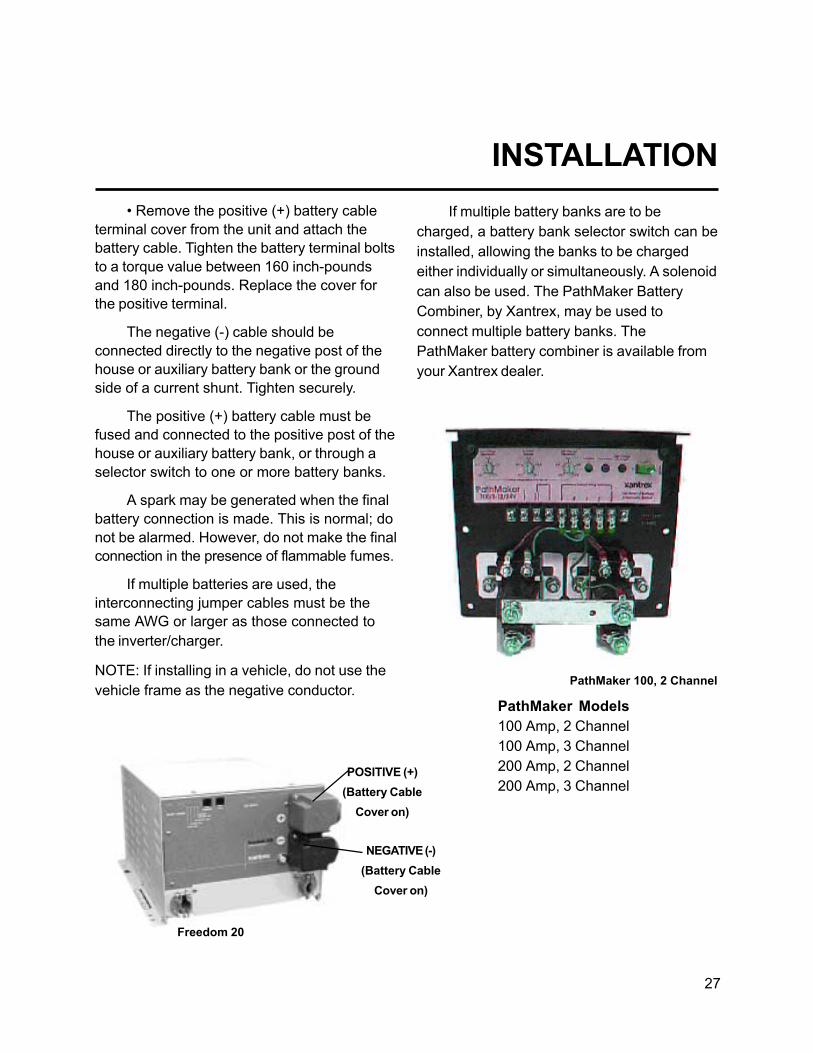
� Remove the positive (+) battery cableterminal cover from the unit and attach thebattery cable. Tighten the battery terminal boltsto a torque value between 160 inch-poundsand 180 inch-pounds. Replace the cover forthe positive terminal.
The negative (-) cable should beconnected directly to the negative post of thehouse or auxiliary battery bank or the groundside of a current shunt. Tighten securely.
The positive (+) battery cable must befused and connected to the positive post of thehouse or auxiliary battery bank, or through aselector switch to one or more battery banks.
A spark may be generated when the finalbattery connection is made. This is normal; donot be alarmed. However, do not make the finalconnection in the presence of flammable fumes.
If multiple batteries are used, theinterconnecting jumper cables must be thesame AWG or larger as those connected tothe inverter/charger.
NOTE: If installing in a vehicle, do not use thevehicle frame as the negative conductor.
If multiple battery banks are to becharged, a battery bank selector switch can beinstalled, allowing the banks to be chargedeither individually or simultaneously. A solenoidcan also be used. The PathMaker BatteryCombiner, by Xantrex, may be used toconnect multiple battery banks. ThePathMaker battery combiner is available fromyour Xantrex dealer.
INSTALLATION
POSITIVE (+)(Battery Cable
Cover on)
PathMaker Models100 Amp, 2 Channel100 Amp, 3 Channel200 Amp, 2 Channel200 Amp, 3 Channel
PathMaker 100, 2 Channel
NEGATIVE (-)(Battery Cable
Cover on)
Freedom 20
28
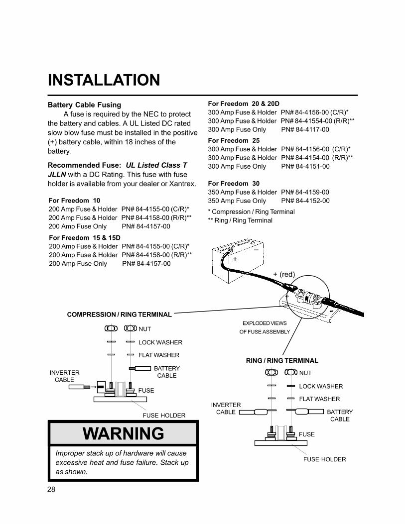
COMPRESSION / RING TERMINAL
INSTALLATION
Improper stack up of hardware will causeexcessive heat and fuse failure. Stack upas shown.
WARNING
Battery Cable FusingA fuse is required by the NEC to protect
the battery and cables. A UL Listed DC ratedslow blow fuse must be installed in the positive(+) battery cable, within 18 inches of thebattery.
Recommended Fuse: UL Listed Class TJLLN with a DC Rating. This fuse with fuseholder is available from your dealer or Xantrex.
RING / RING TERMINAL
For Freedom 20 & 20D300 Amp Fuse & Holder PN# 84-4156-00 (C/R)*300 Amp Fuse & Holder PN# 84-41554-00 (R/R)**300 Amp Fuse Only PN# 84-4117-00For Freedom 25300 Amp Fuse & Holder PN# 84-4156-00 (C/R)*300 Amp Fuse & Holder PN# 84-4154-00 (R/R)**300 Amp Fuse Only PN# 84-4151-00
For Freedom 30350 Amp Fuse & Holder PN# 84-4159-00350 Amp Fuse Only PN# 84-4152-00* Compression / Ring Terminal** Ring / Ring Terminal
FUSE HOLDER
FUSE
BATTERYCABLE
INVERTERCABLE
FLAT WASHER
LOCK WASHER
NUT
FUSE HOLDER
FUSE
BATTERYCABLEINVERTER
CABLE
FLAT WASHER
LOCK WASHER
NUT
+ (red)
EXPLODED VIEWSOF FUSE ASSEMBLY
+
_
For Freedom 10200 Amp Fuse & Holder PN# 84-4155-00 (C/R)*200 Amp Fuse & Holder PN# 84-4158-00 (R/R)**200 Amp Fuse Only PN# 84-4157-00
For Freedom 15 & 15D200 Amp Fuse & Holder PN# 84-4155-00 (C/R)*200 Amp Fuse & Holder PN# 84-4158-00 (R/R)**200 Amp Fuse Only PN# 84-4157-00

29
INSTALLATIONFollow these instructions to ensure
proper start up and confirm that the installationis correct.
1. Check to make sure Invert and Chargeare OFF. The INVERT LED should not beilluminated, the CHARGE LED should beblinking (charger ready but no external ACpower available). If using a Remote ControlPanel or a Link Instrument, make sure inverterand charger are OFF.
2. Check battery polarity. If the unit wasconnected to the battery with reverse polarity,the unit will be damaged.
3. Check the battery voltage and ensureit is within proper range for the unit (10�15.5VDC).
4. Install the jumper in the AuxiliarySwitch port (AUX SWITCH), if using the inverterwithout remote. If operating the inverter with aremote, the jumper should not be used.
Do not apply shorepower orgenerator power without performing thefollowing steps:
1. Test the inverter function: � With no loads connected to the output ofthe inverter, turn the INVERT Switch ON. TheINVERT LED should be blinking green. If usinga remote, turn ON the inverter with the switchon the Remote Control Panel or Link Instrument.
� The Freedom Inverter/Charger will producea slight buzz. If using a Freedom RemoteControl Panel or Link Instrument the INVERT/CHARGE LEDs will illuminate and the voltageindicator will display the battery voltage. TheDC Amps LED will not be lit because the unitis in the idle mode.
Do not turn the inverter ON beforeeliminating any possibility of backfeed.
WARNING
� Add a load of 7 watts or more to the outputof the inverter. A 40 watt incandescent lightbulb will work fine. The DC Amps LEDs on theremote will indicate the DC draw from thebattery through the inverter.
� Leave the load connected and turn OFF theINVERT mode by pressing the INVERT switchor turn OFF the INVERT mode from the FreedomRemote Control Panel or Link Instrument.
2. Test the transfer function: � Be sure the unit is OFF�the INVERT andCHARGE LEDs are not illuminated. Applyshorepower. If there is a backfeed in theinstallation, the unit will protect itself, the LOWBATTERY and OVERTEMP/OVERLOAD LEDwill both be blinking rapidly (five times persecond). Do not proceed until the backfeedcondition has been corrected. � Once shorepower has been applied to theunit, there will be approximately an 8-seconddelay. Then the unit should transfer shorepowerand power the load. If this does not happen, donot proceed. If the LOW BATTERY and OVER-LOAD/OVERTEMP LEDs are blinking rapidlyor if you are using a Freedom Remote ControlPanel or Link Instrument, check the panel forbackfeed indication. The panel will show anoverload condition. Eliminate the backfeedcondition.

30
NOTE: For low power system shutdownmode, both the INVERT and CHARGE LEDsmust be OFF.
� Testing for backfeed. If a backfeedcondition is indicated, disconnect fromshorepower and disconnect the AC outputwires on the inverter. Make sure the inverter isOFF. Apply shorepower and measure forvoltage between the black and white wires thatwere attached to the inverter output feeding theelectrical panel or loads, not the inverter outputwires. If there is voltage on these wires, abackfeed condition exists and must becorrected or damage will result.
3. Test the battery charger function: � With shorepower applied and thetransfer switch engaged, the battery chargershould be in operation. The CHARGE LED willblink for 8 seconds. After the 8 seconds, theunit will enter the charge mode and the LEDwill be illuminated. (NOTE: When usingTemperature Sensitive Charging, this time maybe longer.)
NOTE: When AC is available, the unit willautomatically default to charge mode withoutthe operator setting the unit in CHARGE mode.It is necessary to press the CHARGE switchOFF, if you do not want to charge.
Verify the charger is working by using avoltmeter. The battery voltage should graduallyincrease. If using a Freedom Remote ControlPanel, the DC Amps LED indicates the currentthe charger is putting out and the DC VoltsLED indicates an increase in battery voltage.
INSTALLATION � Turn the INVERT ON, the green LEDshould blink. Remove shorepower and theinverter should automatically pick up the ACload when shorepower is removed.
Repeat the test for transfer and batterycharger with the generator if you have one.
Congratulations, you have completed asuccessful installation.

31
TROUBLESHOOTING LED STATUSsutatSDEL sutatSnoitarepO setoN
TREVNI EGRAHC YRETTABWOL PMETREVODAOLREVO
neerGdiloS neerGgniknilB FFO FFO ontubydaerregrahC.gnitrevnI.elbaliavaCAlanretxe
lamroN
gniknilBneerG
neerGdiloS FFO FFO .ybdnatsnisiretrevnI.degrahcgniebsiyrettaB
tnerrucgnigrahc,lamroNsdeecxedaolCAfidetimil
.gnittesgnirahSrewoP
gniknilBneerG
FFO FFO FFO .ybdnatsnisiretrevnI.ffodenrutyllaunamregrahC
devomersirewopCAfIregrahceht,deilppaerdna
.NOnrutyllacitamotualliw
FFO neerGdiloS FFO FFO .gnigrahC.FFOretrevnI ybretrevniehtteseR.nottubTREVNIgnihsup
.knilbdluohsDEL
neerGdiloS neerGgniknilB deRdiloS * ontubydaerregrahC.gnitrevnIyrettaB.elbaliavaCAlanretxe
:gninraWegatloVV51>CDV<V01
egatlovyrettaB.gninraWnahteromro01nahtssel
stlov51
neerGdiloS neerGgniknilB * deRdiloS ontubydaerregrahC.gnitrevnI-revO.elbaliavaCAlanretxe
gninraWerutarepmet
.nwodtuhsretrevnI.gninraW
FFO neerGgniknilB gniknilBwolSdeR
* :nwodtuhsegatloVyrettaBV51>CDV<V01
.nwodtuhSretrevnInehwemuserlliwnoitarepO
stlov5.31sehcaeryrettab
FFO neerGgniknilB * gniknilBwolSdeR
lanretxeontubydaerregrahCregrahC.elbaliavarewopCA
nwodtuhSerutarepmet-revo
yllacitamotualliwnoitarepOsahtinuretfaemuser
nwoddelooc
FFO neerGgniknilB * gniknilBtsaFdeR
nwodtuhSdaolrevOretrevnI yllaunaM.daolCAecudeRmetsysehttratser
FFO neerGgniknilB gniknilBtsaFdeR
gniknilBtsaFdeR
tcerrocnI.nwodtuhSdeefkcaBgniriwCA
erofebgniriwniCAtcerroCehttratseryllaunaM.esu
.metsys
FFO neerGgniknilB gniknilBtsaFdeR
FFO elppiRyrettaB gninraW
.sutatsFFOroNOrehtieebdluoC*

32

33
Alternating Current (AC) An electric currentthat reverses direction at regular intervals.Sources of alternating current are shorepower, generator power, inverter power orhousehold current.
Ampere (Amp, A) The unit of measure ofelectron flow rate of current through a circuit.
Ampere-hour (Amp-Hr., Ah) A unit ofmeasure for a battery�s electrical storagecapacity, obtained by multiplying the current inamperes by the time in hours of discharge(Example: a battery which delivers 5 amperesfor 20 hours delivers 5 amperes times 20hours, or 100 Ah of capacity.)
Ampere-Hour Capacity The ability of a fullycharged battery to deliver a specified quantityof electricity (Amp-Hr., Ah) at a given rate(Amp, A) over a definite period of time (Hr.).The capacity of a battery depends upon anumber of factors such as: active material,weight, density, adhesion to grid, number,design and dimensions of plates, plate spacingdesign of separators, specific gravity andquantity of available electrolyte, grid alloys, finallimiting voltage, discharge rate, temperature,internal and external resistance, age and life ofthe battery (bank).
AGM (Absorbed Glass Mat) Battery A leadacid, maintenance-free battery.
AWG (American Wire Gauge) A standardused to measure the size of wire.
Circuit An electric circuit is the path of anelectric current. A closed circuit has acomplete path. An open circuit has a broken ordisconnected path.
Circuit (Series) A circuit which has only onepath for the current to flow. Batteries arrangedin series are connected with the negative of the
GLOSSARYfirst to the positive of the second, negative ofthe second to the positive of the third, etc. Iftwo 6-volt batteries of 50 ampere hourscapacity are connected in series, the circuitvoltage is equal to the sum of the two batteryvoltages, or 12 volts, and the ampere-hourcapacity of the combination is 50 amperehours.
Circuit (Parallel) A circuit which providesmore than one path for current flow. A parallelarrangement of batteries (of like voltage andcapacity) would have all positive terminalsconnected to a conductor and all negativeterminals connected to another conductor. Iftwo 12-volt batteries of 50 ampere-hourcapacity each are connected in parallel, thecircuit voltage is 12 volts, and the ampere-hourcapacity of the combination is 100 amperehours.
Current The rate of flow of electricity or themovement rate of electrons along a conductor.It is comparable to the flow of a stream of water.The unit of measure for current is ampere.
Cycle In a battery, one discharge plus onerecharge equals one cycle.
Direct Current (DC) Current that flowscontinuously in one direction such as that frombatteries, photovoltaics, alternators, chargersand DC generators.
34
Equalize Charge A controlled overcharge ofthe batteries which brings all cells up to thesame voltage potential, extends the battery life,restores capacity and mixes the electrolyte.This can only be done using the FreedomRemote Control Panel or a Link Instrument.
Gel Cell Battery A type of battery that uses agelled electrolyte solution. These batteries aresealed and are virtually maintenance free. Notall sealed batteries are the gel cell type.
GFCI (Ground Fault Circuit Interrupter) Aprotective device that rapidly de-energizes acircuit when current to ground exceeds apredetermined value.
Ground The reference potential of a circuit. Inautomotive use, the result of attaching onebattery cable to the body or frame which isused as a path for completing a circuit in lieu ofa direct wire from a component. This methodis not suitable for connecting the negativecable of the inverter to ground. Instead, routethe cable directly to the negative terminal of thebattery.
LED (Light Emitting Diode) Indicator light.
LINK Instrument These panels monitor singleand dual battery banks. Some models provideremote management of Freedom Inverter/Chargers. Available in five models: LINK 10,LINK 20, LINK 1000, LINK 2000, and LINK2000-R.
NEC National Electric Code
Negative Designating or pertaining toelectrical potential. The negative terminal is thepoint from which electrons flow duringdischarge.
Ohm A unit for measuring electricalresistance.
Ohm�s Law Expresses the relationshipbetween Voltage (V) and Current (I) in anelectrical circuit with resistance (R). It can beexpressed as follows: V=IR. If any two of thethree values are known, the third value can becalculated by using the above formula.
Positive Designating or pertaining to electricalpotential; opposite of negative. The positivebattery terminal is the point where electronsreturn to the battery during discharge.
Power Sharing The feature of the charger toreduce its output when the AC power beingconsumed by the charger and external ACloads connected to the output of the inverterare in excess of the input breaker rating.
TSC Abbreviation for Temperature SensitiveCharging. The ability of the charger to adjust itscharging voltage based on the temperaturesensed at the battery bank if a temperatureprobe is used.
Volt The unit of measure for electric potential.
Watt The unit for measuring electrical power,such as the rate of doing work, in movingelectrons by or against an electric potential.
Watt-Hour (Watt-HR, Wh) The unit formeasuring electrical energy which equalswatts x hours.
Wet Cell Battery A type of battery that usesliquid as an electrolyte. The wet cell batteryrequires periodic maintenance: cleaning theconnections, checking the electrolyte level andperforming an equalization cycle.
GLOSSARY

35
SPECIFICATIONSledoM )seireS854(01 )seireS854(*D51dna51 )seireS854(*D02dna02 seireS854(52 )seireS854(03
rebmuNtraP 21-0101-18 -0251-18dna21-0151-1821
-0202-18dna21-0102-1821
21-0152-18 21-0103-18
egatloVyrettaBlanimoN CDV21 CDV21 CDV21 CDV21 CDV21
egnaRegatloVyrettaB CDV5.51-01 )2.0-/+(CDV5.51-0.01 )2.0-/+(CDV5.51-0.01 )2.0-/+(CDV5.51-0.01 CDV5.51-0.01
tuotuCyrettaBwoL CDV5.0-/+01 )5.0-/+(CDV0.01 )5.0-/+(CDV0.01 )5.0-/+(CDV0.01 )5.0-/+(CDV0.01
egnaRegatloVtupnICA CAV09muminiMCAV031lamroN
CAV09muminiMCAV031lamroN
CAV09muminiMCAV031lamroN
CAV09muminiMCAV031lamroN
CAV09muminiMCAV031lamroN
noitalugeRycneuqerF ztrauQzH06ro05detalugeR
ztrauQzH06ro05detalugeR
ztrauQzH06ro05detalugeR
ztrauQzH06ro05detalugeR
ztrauQzH06ro05detalugeR
rewoPtuptuOretrevnI)suounitnoC(
AV0001 AV0051 AV0002 AV0052 AV0003
egatloVretrevnInoitalugeR
SMReurT%5-/+V021 SMReurT%5-/+V021 SMReurT%5-/+V021 SMReurT%5-/+V021 SMReurT%5-/+V021
epahSevaW evaWeniSdeifidoM evaWeniSdeifidoM evaWeniSdeifidoM evaWeniSdeifidoM evaWeniSdeifidoM
rewoPegruS spmA52 spmA5.73 spmA05 spmA5.26 spmA57
niarDtnerruCdaoLoN)edoMeldI(
spmA21. pmA21. pmA21. spmA21. spmA21.
dewollAsrotcaFrewoP llA llA llA llA llA
ycneiciffEdaoLlluF )zH06(%58 )zH06(%68 )zH06(%58 %78 )zH06( %68 )zH06(
ycneiciffEkaeP %39 %29 %39 %39 %39
noitcetorP ytilitUrednU/revOrednU/revO,egataloV-trohS,egatloVyrettaB,rekaerBtiucriC,tiucriC
,erutarepmeTrevOdeefkcaB
,egatloVytilitUrednU/revOyrettaBrednU/revO
,tiucriC-trohS,egatloVrevO,rekaerBtiucriC
deefkcaB,erutarepmeT
,egatloVytilitUrednU/revOyrettaBrednU/revO
,tiucriC-trohS,egatloVrevO,rekaerBtiucriC
deefkcaB,erutarepmeT
,egatloVytilitUrednU/revOyrettaBrednU/revO
tiucriC-trohS,egatloVrevO,rekaerB
deefkcaBerutarepmeT
,egatloVytilitUrednU/revOyrettaBrednU/revO
,tiucriC-trohS,egatloVrevO,rekaerBtiucriC
deefkcaB,erutarepmeT
etaRgnigrahC )egats-3(spmA05 )egats-3(spmA57 )egats-3(spmA001 )egats-3(spmA031 )egats-3(spmA041
tupnICA)edoMegrahC.xaM(
spmA21 spmA71 spmA12 spmA62 spmA82
egatloVegrahCkluB **3.41 **CDV3.41 **CDV3.41 **CDV3.41 **CDV3.41
egatloVegrahCtaolF **CDV4.31 **CDV4.31 **CDV4.31 **CDV4.31 CDV4.31 **
egrahCgnizilauqEegatloV
CDV3.61 **CDV3.61 **CDV3.61 **CDV3.61 **CDV3.61
lenaPsutatS kniLroetomeRlanoitpO kniLroetomeRlanoitpOstnemurtsnI
kniLroetomeRlanoitpOstnemurtsnI
kniLroetomeRlanoitpOstnemurtsnI
kniLroetomeRlanoitpOstnemurtsnI
thgieW .sbl53 .sbl54 .sbl54 sbl05 .sbl05
snoisnemiD H"9.7xW"5.11xL"2.31 H"9.7xW"5.11xL"2.31 H"9.7xW"5.11xL"2.31 H"9.7xW"5.11xL"2.31 H"9.7xW"5.11xL"2.31
tuptuOCAlauD*regrahc/retrevniehtnodetcelesepyTyrettaBybelbatsujdadnadellatsnirosneSerutarepmeThtiwtinunoelbairaV**
.lenaPlortnoCetomeRehtmorfrolenaplortnoc

36
WARRANTYWhat does this warranty cover?
This Limited Warranty is provided by Xantrex Technology, Inc. (�Xantrex�) and covers defects in workmanship andmaterials in your Xantrex Freedom 458 Inverter/Charger. This warranty lasts for a Warranty Period of 30 months fromthe date of purchase at point of sale to you, the original end user customer.
This Limited Warranty is transferable to subsequent owners but only for the unexpired portion of the WarrantyPeriod.
What will Xantrex do?
Xantrex will, at its option, repair or replace the defective product free of charge, provided that you notify Xantrex ofthe product defect within the Warranty Period, and provided that Xantrex through inspection establishes theexistence of such a defect and that it is covered by this Limited Warranty.
Xantrex will, at its option, use new and/or reconditioned parts in performing warranty repair and building replacementproducts. Xantrex reserves the right to use parts or products of original or improved design in the repair orreplacement. If Xantrex repairs or replaces a product, its warranty continues for the remaining portion of the originalWarranty Period or 90 days from the date of the return shipment to the customer, whichever is greater. All replacedproducts and all parts removed from repaired products become the property of Xantrex.
Xantrex covers both parts and labor necessary to repair the product, and return shipment to the customer via aXantrex-selected non-expedited surface freight within the contiguous United States and Canada. Alaska and Hawaiiare excluded. Contact Xantrex Customer Service for details on freight policy for return shipments outside of thecontiguous United States and Canada.
How do you get service?
If your product requires troubleshooting or warranty service, contact your merchant. If you are unable to contactyour merchant, or the merchant is unable to provide service, contact Xantrex directly at:
Phone: 1-800-670-0707 (toll free), 1-604-422-2777 (direct)Fax: 1-604-420-2145Email: [email protected]
Direct returns may be performed according to the Xantrex Return Material Authorization Policy described in yourproduct manual. For some products, Xantrex maintains a network of regional Authorized Service Centers. Call Xantrexor check our website to see if your product can be repaired at one of these facilities.
In any warranty claim, dated proof of purchase must accompany the product and the product must not have beendisassembled or modified without prior written authorization by Xantrex.
Proof of purchase may be in any one of the following forms:
• The dated purchase receipt from the original purchase of the product at point of sale to the end user, or• The dated dealer invoice or purchase receipt showing original equipment manufacturer (OEM) status, or• The dated invoice or purchase receipt showing the product exchanged under warranty

37
WARRANTYWhat does this warranty not cover?
This Limited Warranty does not cover normal wear and tear of the product or costs related to the removal,installation, or troubleshooting of the customer�s electrical systems. This warranty does not apply to and Xantrex willnot be responsible for any defect in or damage to:
a) the product if it has been misused, neglected, improperly installed, physically damaged or altered, eitherinternally or externally, or damaged from improper use or use in an unsuitable environment;
b) the product if it has been subjected to fire, water, generalized corrosion, biological infestations, or inputvoltage that creates operating conditions beyond the maximum or minimum limits listed in the Xantrexproduct specifications including high input voltage from generators and lightning strikes;
c) the product if repairs have been done to it other than by Xantrex or its authorized service centers (hereafter�ASCs�);
d) the product if it is used as a component part of a product expressly warranted by another manufacturer;e) the product if its original identification (trade-mark, serial number) markings have been defaced, altered, or
removed.
Disclaimer
Product
THIS LIMITED WARRANTY IS THE SOLE AND EXCLUSIVE WARRANTY PROVIDED BY XANTREX INCONNECTION WITH YOUR XANTREX PRODUCT AND IS, WHERE PERMITTED BY LAW, IN LIEU OF ALLOTHER WARRANTIES, CONDITIONS, GUARANTEES, REPRESENTATIONS, OBLIGATIONS AND LIABILITIES,EXPRESS OR IMPLIED, STATUTORY OR OTHERWISE IN CONNECTION WITH THE PRODUCT, HOWEVERARISING (WHETHER BY CONTRACT, TORT, NEGLIGENCE, PRINCIPLES OF MANUFACTURER�S LIABILITY,OPERATION OF LAW, CONDUCT, STATEMENT OR OTHERWISE), INCLUDING WITHOUT RESTRICTION ANYIMPLIED WARRANTY OR CONDITION OF QUALITY, MERCHANTABILITY OR FITNESS FOR A PARTICULARPURPOSE. ANY IMPLIED WARRANTY OF MERCHANTABILITY OR FITNESS FOR A PARTICULAR PURPOSETO THE EXTENT REQUIRED UNDER APPLICABLE LAW TO APPLY TO THE PRODUCT SHALL BE LIMITED INDURATION TO THE PERIOD STIPULATED UNDER THIS LIMITED WARRANTY.IN NO EVENT WILL XANTREX BE LIABLE FOR ANY SPECIAL, DIRECT, INDIRECT, INCIDENTAL ORCONSEQUENTIAL DAMAGES, LOSSES, COSTS OR EXPENSES HOWEVER ARISING WHETHER IN CONTRACTOR TORT INCLUDING WITHOUT RESTRICTION ANY ECONOMIC LOSSES OF ANY KIND, ANY LOSS ORDAMAGE TO PROPERTY, ANY PERSONAL INJURY, ANY DAMAGE OR INJURY ARISING FROM OR AS ARESULT OF MISUSE OR ABUSE, OR THE INCORRECT INSTALLATION, INTEGRATION OR OPERATION OF THEPRODUCT.
Exclusions
If this product is a consumer product, federal law does not allow an exclusion of implied warranties. To the extent youare entitled to implied warranties under federal law, to the extent permitted by applicable law they are limited to theduration of this Limited Warranty. Some states and provinces do not allow limitations or exclusions on impliedwarranties or on the duration of an implied warranty or on the limitation or exclusion of incidental or consequentialdamages, so the above limitation(s) or exclusion(s) may not apply to you. This Limited Warranty gives you specificlegal rights. You may have other rights which may vary from state to state or province to province.

38
Warning: Limitations On Use
Please refer to your product user manual for limitations on uses of the product. Specifically, please note that theFreedom 458 Inverter/Charger is not intended for use in connection with life support systems and Xantrex makes nowarranty or representation in connection with any use of the product for such purposes.
Please note that the Freedom 458 Inverter/Charger is not intended for use as an uninterruptible power supply andXantrex makes no warranty or representation in connection with any use of the product for such purposes.
Return Material Authorization Policy
Before returning a product directly to Xantrex you must obtain a Return Material Authorization (RMA) number andthe correct factory �Ship To� address. Products must also be shipped prepaid. Product shipments will be refused andreturned at your expense if they are unauthorized, returned without an RMA number clearly marked on the outside ofthe shipping box, if they are shipped collect, or if they are shipped to the wrong location.
When you contact Xantrex to obtain service, please have your instruction manual ready for reference and beprepared to supply:
• The serial number of your product• Information about the installation and use of the unit• Information about the failure and/or reason for the return• A copy of your dated proof of purchase
Return Procedure1. Package the unit safely, preferably using the original box and packing materials. Please ensure that your product
is shipped fully insured in the original packaging or equivalent. This warranty will not apply where the productis damaged due to improper packaging.
2. Include the following:• The RMA number supplied by Xantrex Technology Inc clearly marked on the outside of the box.• A return address where the unit can be shipped. Post office boxes are not acceptable.• A contact telephone number where you can be reached during work hours• A brief description of the problem
3. Ship the unit prepaid to the address provided by your Xantrex customer service representative.
If you are returning a product from outside of the USA or Canada
In addition to the above, you MUST include return freight funds and are fully responsible for all documents, duties,tariffs, and deposits.
If you are returning a product to a Xantrex Authorized Service Center (ASC)
A Xantrex return material authorization (RMA) number is not required. However, you must contact the ASC prior toreturning the product or presenting the unit to verify any return procedures that may apply to that particular facility.
WARRANTY

39
INSTALLATION EXAMPLESInstallation examples for the new Freedom 458 Series Inverter/Chargers
Shorepower configurations:
Systems with one 30 Amp single-phase shorepower source with optional generator
Systems with two 30 Amp shorepower sources with optional generator
Systems with a 50 Amp 120 Volt single-phase (3 wire) shorepower source with optionalgenerator
Systems with a 50 Amp 120/240 Volt split-phase (4 wire) shorepower source with optionalgenerator
Inverter/charger configurations:
Single Input / Single Output Freedom 458 Model 10, 15, 20, 25, and 30Single Input / Dual Output (Freedom 458 Model 15 S/D or 20 S/D only)Dual Input / Dual Output Freedom 458 Model 20 D/D, 25 D/D and 30 D/D· Can be connected with single in /single out mode· Can be connected with dual in / single out mode· Can be connected with dual in / dual out mode
The following installation examples are the most commonly used applications involvingspecific shorepower connections, generator power options, and AC load configurations.
Freedom 458 DC Cable and Fuse General Guide
Typical Cable AWG by Length *Model Fuse Size DC Amps 1�3 ft. 3�6 ft. 6�10 ft.F-10 200 A 100 A 2 2 1/0F-15 200 A 150 A 1/0 1/0 2/0F-20 300 A 200 A 2/0 2/0 3/0F-25 300 A 250 A 2/0 3/0 3/0F-30 350 A 300 A 3/0 3/0 4/0*This guide is intended to provide general recommendations for fuse and cable sizing. Always consultLocal and National Electrical Codes for proper fuse and cable size prior to installation.The chassis grounding wire must be no smaller then 1 gauge under that of the Positive battery cable.

40
Installation Option #1 for Freedom 10, 15, 20, 25, and 30
The inverter is used in a Single Input / Single Output mode. Up to 30 Amps is transferredthrough the Freedom unit with the charger sharing power with all of the AC loads.
In this installation example, a single 30 Amp shorepower source is available and all AC loads aresupplied power through the inverter in charge/transfer mode, or by the inverter in invert mode.The charger shares power with the AC loads and can transfer up to 30 Amps. When installing aFreedom 20 D/D, 25 D/D or 30 D/D model, AC Input #2 and AC Output #2 wires are not usedand must be capped off. The AC input power must be supplied through a 30 Amp branch ratedmain breaker.
In this type of a system the panel loads would normally not include any heavy loads such asspace heaters, stove, water heaters, air conditioners, AC to DC converters, or other batterychargers. If these types of loads are present, they should be turned OFF when inverter power isbeing used to prevent overloading the inverter or rapidly discharging the battery bank. To avoidthe need for this manual form of energy management, installation option #2, #3, #4, or 5 shouldbe considered.
If a generator is installed in the system, a break-before-make AC transfer switch is used toselect between shore or generator power. The transfer switch AC output is then routed to theinput of the inverter/charger.

41
Freedom 458 Installation Option 1Freedom 458 Model 10, 15, 20, 25, 30
AC Output
AC Input
Ground Bus
Neutral Bus
Inverter AC Sub Panel
ToInverter
ACLoads
12 VDC Battery Bank
OptionalGenerator
30 A Main Breaker
Transfer Switch
30 A Shorepower
Class TFuse
Single Input/ Single Output30 Amp Transfer Switch PowerShares with Charger.** Always consult Local and NationalElectrical Codes for proper wire sizeprior to installation.
10/3AWGWire**
-+
HotBus
AC Wire Colors
Hot = BlackNeutral = WhiteGround = Green/bare
+
-
30 A
Hot (Line) Neutral
Ground
Freedom 458Inverter/Charger

42
Installation Option #2 for Freedom 10, 15, 20, 25, and 30
The inverter is used in Single Input / Single Output mode. The AC loads are split be-tween main loads and �inverter loads�. The external sources of AC power can be a single30 Amp shorepower source or a 30 Amp breaker from a panel fed by a 50 Amp 120 Voltsingle phase (3 wire) shorepower source, 1 leg of a 50 Amp 120/240 split phase (4 wire)shorepower source, or a generator. The charger shares power with the �inverter loads�only.
In this installation example, one single-phase shorepower source is available or only one leg of asplit-phase source is used to supply the AC input of the inverter/charger. It is highlyrecommended that only the lighter appliance and outlet circuits be connected to the Inverter ACPanel. These loads are supplied power through the inverter in charge/transfer mode, or by theinverter in invert mode. The charger shares power with the �inverter loads� only and can transferup to 30 Amps. The heavier loads such as space heaters, stove, water heater, air conditioners,AC to DC converters, or other battery chargers, should remain connected to the Main AC Panel.These loads are only supplied by shore or generator power from the main panel. This split loadapproach will help avoid problems such as overloading the inverter or rapidly discharging thebattery bank, and eliminate the need to manually manage the energy usage of these loads whenusing inverter power.
The inverter AC input must be supplied power from a 30 Amp breaker in the main panel and fromthe main neutral bus. The inverter�s AC output supplies a separate sub panel. The applianceand outlet loads are then supplied with power from the inverter hot and neutral bus in the subpanel. When installing a Freedom 20 D/D, 25 D/D or 30 D/D model, AC Input #2 and AC Output#2 are not used and must be capped off.
If a generator is installed in the system, a break-before-make AC transfer switch is used toselect between shore or generator power. The transfer switch AC output is then routed to theMain AC Panel.
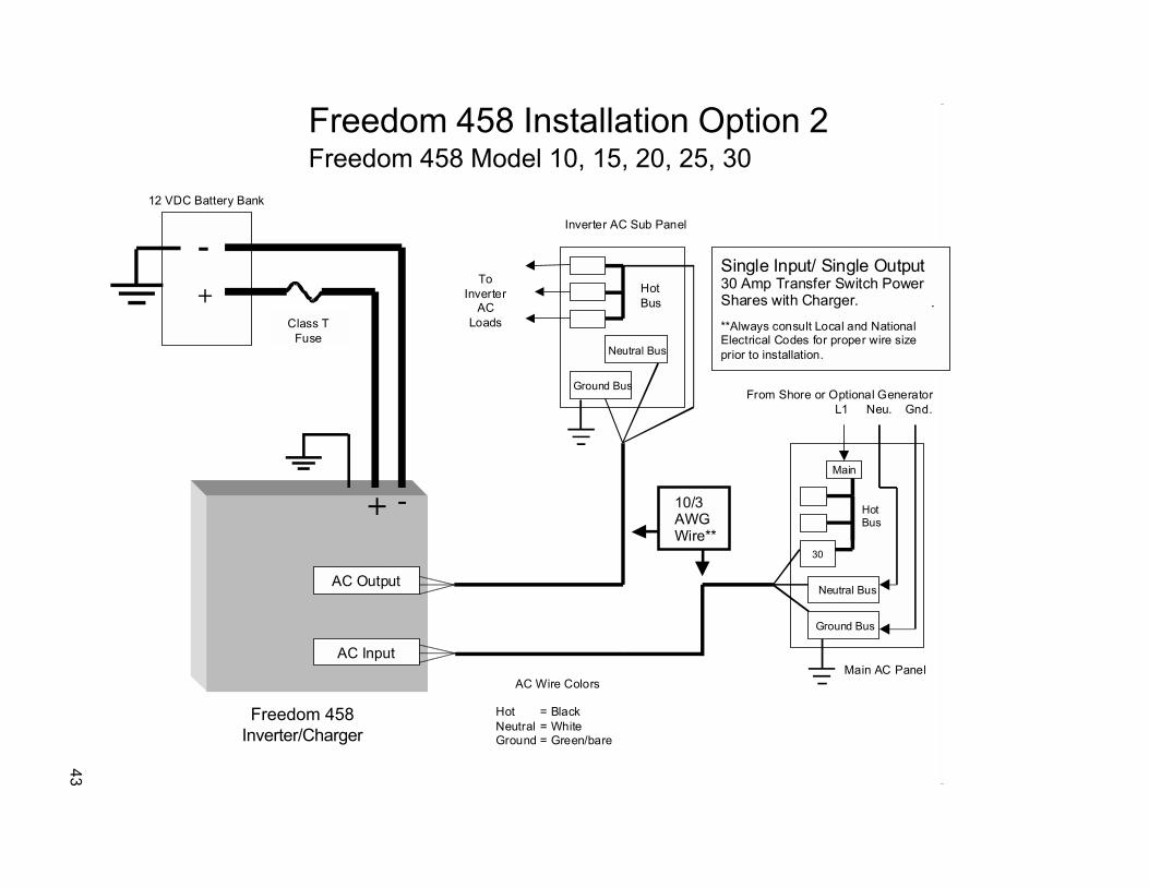
43
AC Output
AC Input
Ground Bus
Neutral Bus
Inverter AC Sub Panel
ToInverter
ACLoads
12 VDC Battery Bank
Class TFuse
Single Input/ Single Output30 Amp Transfer Switch PowerShares with Charger. .**Always consult Local and NationalElectrical Codes for proper wire sizeprior to installation.
10/3AWGWire**
-+
+
-HotBus
Neutral Bus
Ground Bus
30
From Shore or Optional GeneratorL1 Neu. Gnd.
Main AC Panel
HotBus
AC Wire Colors
Hot = BlackNeutral = WhiteGround = Green/bare
Main
Freedom 458 Installation Option 2Freedom 458 Model 10, 15, 20, 25, 30
Freedom 458Inverter/Charger

44
Installation Option #3 for Freedom 20 D/D, 25 D/D and 30 D/D
The inverter is used in Dual Input / Single Output mode. The AC loads are split betweenmain loads and �inverter loads�. The external sources of AC power can be two different30 Amp shorepower sources (both neutrals and both �Hots� must be kept separate) ortwo 30 Amp breakers from a panel fed by a 50 Amp 120 Volt single phase (3 wire)shorepower source, a 50 Amp 120/240 volt split phase (4 wire) shorepower source, or agenerator. The charger has its own 30 Amp source of power (AC input 1) and the other30 Amp source (AC input 2) transfers through the inverter to the �inverter loads� (ACoutput 2). There is no power sharing between the charger and the �inverter loads� inthis mode.
It is highly recommended that only the lighter appliance and outlet circuits be connected to theInverter AC Panel. These loads are supplied power through the inverter in transfer mode, or bythe inverter in invert mode. The heavier loads such as space heaters, stove, water heater, airconditioners, AC to DC converters, or other battery chargers, should remain connected to theMain AC Panel. These loads are only supplied by shore or generator power from the mainpanel. This split load approach will help avoid problems such as overloading the inverter orrapidly discharging the battery bank, and eliminate the need to manually manage the energyusage of these loads when using inverter power.
The inverter AC Input #1 must be supplied power from a 30 Amp breaker and neutral in the mainpanel and is used to power the charger only. AC Input #2 must be supplied by a second 30 Ampbreaker and neutral in the main panel which transfers through the inverter to AC Output #2.These two input breakers can be supplied by the same phase or by opposite phases. Theinverter AC Output #2 supplies a separate sub panel. The appliance and outlet loads are thensupplied with power from the inverter hot and inverter neutral bus in the sub panel. AC Output#1 is not used and must be capped off.
If a generator is installed in the system, a break-before-make AC transfer switch is used to se-lect between shore or generator power. The transfer switch AC output is then routed to the MainAC Panel.
If only AC Input #1 is supplied power, the unit will charge and power share with and transferpower to the loads on AC Output # 2.
If only AC Input #2 is supplied power, the unit will not charge, and will only transfer 30 Ampsthrough to the inverter loads connected to AC Output #2.

45
AC Output 2
AC Output 1
AC Input 2
AC Input 1
Ground Bus
Neutral Bus
Cap* Off eachwire separately
Inverter AC Sub Panel
ToInverter
ACLoads
12 VDC Battery Bank
Class TFuse
Freedom 458 Installation Option 3Freedom 458 Model 20 D/D, 25 D/D, 30 D/D
Dual Input/ Single Output30 Amp TransferSeparate Charge InputPower Sharing Not Active
**Always consult Local and NationalElectrical Codes for proper wire sizeprior to installation..
Freedom 458Inverter/Charger
10/3AWGWire**
-+
+
-HotBus
Neutral Bus
Ground Bus
30
From Shore or Generator L1 NeuL2 Gnd.
Main AC Panel
30
AC Wire Colors
Hot = BlackNeutral = WhiteGround = Green/bare
Main Main

46
Installation Option #4 for Freedom 20 D/D, 25 D/D and 30 D/D
The inverter is used in Dual Input / Dual Output mode. The AC loads are split betweenmain loads and �inverter loads�. The external sources of AC power can be two different30 Amp shorepower sources (both neutrals and both �Hots� must be kept separate) ortwo 30 A breakers from a panel fed by a 50 Amp 120 Volt single phase (3 wire)shorepower source, a 50 Amp 120/240 Volt split phase (4 wire) shorepower source, or agenerator. The charger power shares a 30 Amp source (AC input 1) with the �inverterloads� connected to AC Output #1 and the other 30 Amp source (AC input 2) transfersthrough the inverter to the �inverter loads� connected to AC Output #2. In invertermode, the inverter powers both groups of �inverter loads� (AC output 1 and 2). Incharge/transfer mode, up to 60 Amps can be transferred to the �inverter loads�. The �in-verter loads� are split into two groups so that these loads can be used to help balancethe two legs of shore or generator power.
It is highly recommended that only the lighter appliance and outlet circuits be connected to theInverter AC Panel. These loads are supplied power through the inverter in transfer mode, or bythe inverter in invert mode. The heavier loads such as space heaters, stove, water heater, airconditioners, AC to DC converters, or other battery chargers, should remain connected to theMain AC Panel. These loads are only supplied by shore or generator power from the main panel.This split load approach will help avoid problems such as overloading the inverter or rapidlydischarging the battery bank, and eliminate the need to manually manage the energy usage ofthese loads when using inverter power.
The inverter AC Input #1 must be supplied power from a 30 Amp breaker and neutral in the mainpanel and is used to power the charger and transfer up to 30 Amps through to the �inverterloads� connected to AC Output #1. AC Input #2 must be supplied by a second 30 Amp breaker inthe main panel which transfers through the inverter to AC Output #2. These two input breakerscan be supplied by the same phase or by opposite phases. The inverter AC outputs supply aseparate sub panel. The appliance and outlet loads are then supplied with power from the in-verter hot and inverter neutral buses in the sub panel.
If a generator is installed in the system, a break-before-make AC transfer switch is used toselect between shore or generator power. The transfer switch AC output is then routed to theMain AC Panel.
If only AC Input #1 is supplied power, the unit will charge and transfer up to 30 Amps through toboth groups of �inverter loads� (AC output 1 and 2). The charger will power share with bothgroups of �inverter loads�.
If only AC Input #2 is supplied power, the unit will not charge, and will only transfer 30 Ampsthrough to the inverter loads connected to AC Output #2 only.

47
AC Output 2
AC Output 1
AC Input 2
AC Input 1
Ground Bus
Neutral 2 Bus
Inverter AC Sub PanelL2 L1
12 VDC Battery Bank
Class TFuse
Freedom 458 Installation Option 4Freedom 458 Model 20 D/D, 25 D/D, 30 D/D
Dual Input/ Dual Output30 Amp Transfer of two Legsof power (60 Amps total)
* Two Neutral buses are requiredif Shore Power is suppliedfrom 2/ separate 30 A sources.
**Always consult Local and NationalElectrical Codes for proper wire sizeprior to installation.
Freedom 458Inverter/Charger
10/3AWGWire**
-+
+
-
Neutral Bus
Ground Bus
30
From Shore or Generator L2 Gnd
Main AC Panel
30
Neutral 1 Bus
AC Wire Colors
Hot = BlackNeutral = WhiteGround = Green/bare
*
NeuL1
HotBus
Main Main

48
Installation Option #5 for Freedom 15 S/D and 20 S/D
The inverter is used in Single Input / Dual Output mode. The AC loads are split betweenmain loads and two branch circuits containing �inverter loads� (AC output 1 and AC out-put 2). The external sources of AC power can be a single 30 Amp shorepower source ora 30 Amp breaker from a panel fed by a 50 Amp 120 Volt single phase (3 wire) shorepowersource, 1 leg of a 50 Amp 120/240 Volt split-phase (4 wire) shorepower source, or a gen-erator. The charger shares power with the �inverter loads� only.
In this installation example, one single-phase shorepower source is available or only one leg of asplit phase source is used to supply the AC input of the inverter/charger. It is highlyrecommended that only the lighter appliance and outlet circuits be connected to the Inverterbranch circuits, AC Output 1 and AC Output 2. These loads are supplied power through theinverter in charge/transfer mode, or by the inverter in invert mode. The charger shares powerwith the �inverter loads� only and can transfer up to 30 Amps. The heavier loads such as spaceheaters, stove, water heater, air conditioners, AC to DC converters, or other battery chargers,should remain connected to the Main AC Panel. These loads are only supplied by shore orgenerator power from the main panel. This split load approach will help avoid problems such asoverloading the inverter or rapidly discharging the battery bank, and eliminate the need tomanually manage the energy usage of these loads when using inverter power.
The inverter AC input must be supplied power from a 30 Amp breaker in the main panel and fromthe main neutral bus. The inverter has two AC outputs that are protected by internal branch ratedcircuit breakers, eliminating the need for a separate sub panel. Two appliance and/or outletcircuits are then supplied with power directly from the inverter AC outputs. All 15 Amp outputsshould use 12 or 14 gauge* wires for the output circuit, and all 20 Amp outputs should use 12gauge wires*. Typically a GFI (GFCI) type outlet is used as the first outlet in the line. ConsultLocal and National Electrical Codes for specific GFI installation recommendations.If a generator is installed in the system, a break-before-make AC transfer switch is used toselect between shore or generator power. The transfer switch AC output is then routed to theMain AC Panel.
*Always consult Local and National Electrical Codes for proper wire size prior to installation.
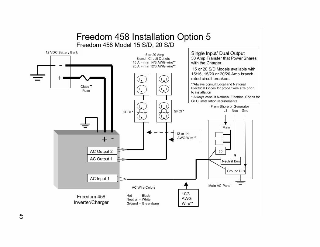
49
AC Output 2
AC Output 1
AC Input 1
12 VDC Battery Bank
Class TFuse
Freedom 458 Installation Option 5Freedom 458 Model 15 S/D, 20 S/D
Single Input/ Dual Output30 Amp Transfer that Power Shareswith the Charger. 15 or 20 S/D Models available with15/15, 15/20 or 20/20 Amp branchrated circuit breakers.**Always consult Local and NationalElectrical Codes for proper wire size priorto installation
Freedom 458Inverter/Charger
10/3AWGWire**
-+
+
-
Neutral Bus
Ground Bus
30
From Shore or Generator L1 Neu Gnd
Main AC Panel
15 or 20 AmpBranch Circuit Outlets
15 A = min 14/3 AWG wire**20 A = min 12/3 AWG wire**
12 or 14 AWG Wire**
AC Wire Colors
Hot = BlackNeutral = WhiteGround = Green/bare
GFCI *GFCI *
* Always consult National Electrical Codes for GFCI installation requirements.
Main

Xantrex Technology Inc.
Toll Free 1 800 670 0707
Direct 1 604 422 2777
Fax 1 604 420 2145
www.xantrex.com
445-0193-01-01 Rev. 2 Printed in the U.S.A.